
ES
EN
Manual de Usuario e Instalación
HTW-AHUKZ01D | HTW-AHUKZ02D | HTW-AHUKZ03D
Por favor lea atentamente antes de usar este producto.
Please, read carefully before using the product.
Owner’s and Installation Manual
AHUKZ
VRF CONTROL BOX KIT


ESPAÑOL
Manual de Usuario e Instalación
AHUKZ
KIT CAJA DE CONTROL VRF
HTW-AHUKZ01D | HTW-AHUKZ02D | HTW-AHUKZ03D

CONTENIDO
1 PRECAUCIONES...........................................................................................01
2 INTRODUCCIÓN ............................................................................................02
3 INSTALACIÓN
3.1 Antes de la instalación ...................................................................................................04
3.2 Elegir un sitio para la instalación ...................................................................................05
3.3 Métodos y tamaño de la instalación ..............................................................................05
3.4 Tubería de refrigerante ..................................................................................................07
3.5 Instalación de los sensores de temperatura ..................................................................10
3.6 Conexión eléctrica ......................................................................................................... 11
4 AJUSTES DE LAS FUNCIONES
4.1 Ajustes de capacidad ....................................................................................................18
4.2 Ajuste de la caja de control AHU maestra/esclava ........................................................18
4.3 Ajustes de la dirección de la caja de control AHU .........................................................18
4.4 Selección del control mediante temp. retorno de aire o la temp. de salida de aire .......19
4.5 Selección de controles ..................................................................................................20
5 DEFINICIÓN DE DIP ......................................................................................23
6 CÓDIGO DE ERROR Y CONSULTA .............................................................26

1 PRECAUCIONES
Asegúrese de cumplir con las leyes y los reglamentos loca-
les, nacionales e internacionales.
Lea cuidadosamente las "PRECAUCIONES" antes de la
instalación.
Las siguientes precauciones incluyen elementos importan-
tes de seguridad. Obsérvelas y recuérdelas en todo mo-
mento.
Tenga este manual a mano para posibles consultas.
La instalación debe ser realizada únicamente por personal
autorizado de acuerdo con los requisitos del NEC y el CEC.
Las precauciones de seguridad aquí enumeradas se divi-
den en dos categorías. En ambos casos se proporciona
importante información de seguridad que se debe leer cui-
dadosamente.
El incumplimiento de un Cuidado puede provocar
lesiones o daños al equipo.
Después de completar la instalación, asegúrese
de que la unidad funcione correctamente durante
la operación de puesta en marcha. Dé instruc-
ciones al cliente sobre cómo operar la unidad y
cómo realizar las operaciones mínimas de man-
tenimiento. Además, informe a los clientes que
deben guardar este Manual de instalación junto
con el Manual del usuario para posibles consul-
tas futuras.
Asegúrese de que solo el personal de manteni-
miento capacitado y cualicado instale, repare o
realice el mantenimiento del equipo.
La incorrecta instalación, reparación y mantenimien-
to puede dar como resultado descargas eléctricas,
cortocircuitos, fugas, incendios u otros daños al
equipo.
Realice la instalación siguiendo estas instruccio-
nes de instalación de forma estricta.
Si la instalación es defectuosa, provocará fugas de
agua, descargas eléctricas e incendios.
Cuando instale la unidad en una habitación
pequeña, tome medidas para evitar que la con-
centración de refrigerante supere los límites de
seguridad permitidos en caso de fugas de refri-
gerante.
Para obtener más información, póngase en contacto
con el establecimiento en el que realizó la compra.
Un exceso de refrigerante en un ambiente cerrado
puede generar una situación de deciencia de oxí-
geno.
Para la instalación, use los accesorios que se en-
tregan con la unidad y las piezas especicadas.
De no ser así, la unidad podría caerse, o podrían
producirse fugas de agua, descargas eléctricas o
incendios.
Instálelo en un lugar resistente y rme que pue-
da soportar el peso de la unidad.
Si el lugar de instalación no es lo suficientemente
resistente o si la instalación no se ha completado
correctamente, el equipo podría caer y causar lesio-
nes.
El aparato debe instalarse a 2,5m por encima del
suelo. El aparato no debe instalarse en un área
destinada a lavandería.
Antes de obtener acceso a los terminales, todos
los circuitos de suministro deben estar desco-
nectados.
CUIDADO
ATENCIÓN
El equipo debe estar posicionado de manera
que el enchufe sea accesible.
La carcasa del aparato debe estar marcada
con palabras o símbolos, e indicar la direc-
ción del ujo de uido.
Para la instalación eléctrica, siga las normas
locales para cableados y las instrucciones de
instalación. Se debe usar un circuito indepen-
diente y una única salida.
Si la capacidad del circuito eléctrico no es sufi-
ciente o hay un defecto en el trabajo eléctrico,
puede producirse un incendio eléctrico.
Use el cable especificado, conéctelo firme-
mente y sujete el cable de manera que no ac-
túe fuerza externa alguna sobre el terminal.
Si la conexión o la jación no es correcta, la co-
nexión puede sobrecalentarse e incendiarse.
El enrutamiento del cableado debe disponer-
se de forma adecuada para que la cubierta de
la placa de control esté correctamente jada.
Si la cubierta de la placa de control no se ja de-
bidamente, puede provocar sobrecalentamiento,
incendios o descargas eléctricas en el punto de
conexión del terminal.
Si el cable de suministro eléctrico está daña-
do, debe ser reemplazado por el fabricante, su
agente instalador o por personas calicadas
con el n de evitar peligros.
Se debe conectar un conmutador de desco-
nexión de todos los polos con una separación
de contacto mínima de 3 mm en cableado jo.
Al realizar la conexión de la tubería, tenga cui-
dado para evitar que entre aire en el ciclo de
refrigeración.
De lo contrario, puede reducirse la capacidad, o
producirse una presión alta anormal en el ciclo
de refrigeración, explosiones y lesiones.
No modifique la longitud del cable de sumi-
nistro eléctrico ni use alargos, y no comparta
la única toma de corriente con otros aparatos
eléctricos.
De lo contrario, pueden producirse incendios o
descargas eléctricas.
Realice el trabajo de instalación especicado
después de tener en cuenta las ráfagas de
viento fuerte, los tifones o los terremotos.
La instalación incorrecta puede provocar la caída
del equipo y causar accidentes.
Si el equipo pierde refrigerante durante la ins-
talación, ventile el área inmediatamente.
Se puede producir gas tóxico si el refrigerante
entra en contacto con el fuego.
Después de completar la instalación, verique
que el refrigerante no tenga fugas.
Se pueden producir gases tóxicos si el refrige-
rante se ltra en la habitación y entra en contacto
con una fuente de fuego, como un calefactor, una
estufa o una cocina.
01

02
CUIDADO
Conecte a tierra el aire acondicionado.
No conecte el cable de tierra a las tuberías de
gas o agua, a los pararrayos ni a los cables de
tierra de la instalación telefónica. Una conexión
a tierra incompleta puede ocasionar descargas
eléctricas.
Asegúrese de instalar un disyuntor para fugas
a tierra.
Si no se instala un disyuntor para fugas a tierra,
pueden producirse descargas eléctricas.
Conecte primero los cables de la unidad ex-
terior y luego conecte los cables de la caja de
control AHU.
No se permite conectar el equipo de aire acon-
dicionado al suministro eléctrico (cableado y tu-
berías incluidos) hasta que la instalación del aire
acondicionado esté terminada.
Siguiendo las instrucciones de este Manual
de instalación, instale la tubería de drenaje
para garantizar un drenaje adecuado y aísle
las tuberías para evitar la condensación.
Una tubería de drenaje inadecuada puede provo-
car fugas de agua y daños materiales.
Instale la caja de control AHU y las ODU, el
cableado del suministro eléctrico y los cables
de conexión a una distancia mínima de 1 m de
los televisores o radios para evitar ruidos o
interferencias en la imagen.
Dependiendo de las ondas de radio, una distan-
cia de 1 m es posible que no sea suciente para
eliminar el ruido.
El aparato no está diseñado para ser utilizado
por niños pequeños o personas enfermas sin
supervisión.
Los niños deben ser supervisados para asegurar-
se de que no jueguen con el aparato.
2 INTRODUCCIÓN
La caja de control AHU puede conectarse a la ODU de la
bomba de calor/recuperación de calor y a la AHU de terce-
ros. Cada AHU de terceros puede conectarse a una caja
de control AHU o a varias cajas de control AHU en una co-
nexión paralela (hasta cuatro). Este manual describe cómo
instalar y operar una caja de control AHU.
Mediante el uso de una caja de control AHU, una unidad
puede ser controlada por la temperatura del retorno de aire
o por la temperatura de la salida de aire.
Cuando se selecciona el control de la temperatura del
retorno de aire, la AHU conectada puede considerarse
como una IDU estándar.
Los usuarios pueden optar por utilizar el control de fá-
brica o un control de terceros.
La caja de control AHU tiene un puerto de entrada de
0-10 V. Se requiere un control de terceros para propor-
cionar 0-10 V de entrada. El requisito de capacidad del
sistema o la temperatura se puede establecer en base a
una entrada de 0-10 V. Para más información, consulte
la Sección 5.2.2 Modo de ajuste de la capacidad de
salida mediante un control de terceros (tipo 1) y Sección
5.2.3 Modo de ajuste de la temperatura mediante un
control de terceros (Tipo 2)
1
2
3
5
6
7
8
4
N.º Piezas y componentes
1Conjunto de la cubierta de la caja de control
eléctrico
2 Conjunto de la caja de piezas electrónicas
3Conjunto de la válvula de expansión
electrónica
4Conjunto de la soldadura de la caja de control
eléctrico
5 Clip
6 Casquillo de cable
7 Anillo de caucho
8Tablero de jación, tubos

0303
3 INSTALACIÓN
Accesorios
Disposición de instalación
Imagen 3-1
NOMBRE FORMA CANTIDAD USO
Manual de Instalación y del
Usuario 1
Control remoto por cable 1 Control remoto por cable
Grupo de cables del adaptador
de la válvula de expansión
electrónica
1
Abrazadera ja del sensor de
temperatura 3
Manguito 3
Tornillo ST3.9x25 4 Asegure la placa de instalación
Tubos plásticos de ampliación 4
Sensor de temperatura
T2B
T2 T2A
TA T1
5
Grupo de cables de conexión
del sensor de temperatura
T2
T1 T2A
TA T2B
5
Amarre ajustable 5
1
5
2
3
7
4
6
8
N.º Nombre Descripción
1 ODU Unidades
exteriores
2Caja de control
AHU -
3
Unidad de
tratamiento de
aire (AHU)
Se suministra en
la instalación
4Tubería de
líquido
Se suministra en
la instalación
5 Tubería de gas Se suministra en
la instalación
6Control remoto
por cable
Control de
fábrica
7Control de
terceros
Se suministra en
la instalación
8
Cableado del
sensor de
temperatura
-
Tabla 3-2 Nombres y funciones

04
3.1 Antes de la instalación
• Es posible conectar una caja de control AHU a una ODU
de bomba de calor o una ODU de recuperación de calor.
• Cuando una caja de control AHU se conecta a una ODU
de recuperación de calor, el sistema no puede conectarse
a la AHU solamente. La relación de capacidad IDU/ODU
de las IDU comunes debe ser de 50%-100%, la de la
caja de control AHU debe ser de 0%-50%, y la de todo el
sistema debe ser de 50%-100%.
• Cuando se usa una caja de control AHU de bomba de
calor y la caja de control AHU se conecta a una ODU
de interiores: Si no se conectan también IDU comunes,
la relación de capacidad IDU/ODU debe ser de 50%-
100%; si se conectan también IDU comunes, la relación
de capacidad IDU/ODU debe ser de 50%-100%, la de la
AHU debe ser de 0%-50%, y la de todo el sistema debe
ser de 50%-100%.
• Cuando se usa una ODU de recuperación de calor y la
caja de control AHU se conecta a una FAPU, la unidad
solo puede ser controlada por la temperatura de la salida
de aire. La capacidad de FAPU de todo el sistema no
debe exceder el 30% de la capacidad de ODU.
• Cuando se emplea una ODU de bomba de calor y la
caja de control AHU se conecta a una FAPU, la unidad
solo puede ser controlada por la temperatura de la salida
de aire. Si no se conectan IDU comunes, la proporción
de capacidad de IDU/ODU debe ser del 50%-100%; si
también se conectan IDU comunes, la capacidad de
FAPU de todo el sistema no debe superar el 30% de la
capacidad de ODU.
• Cuando se conecta una caja de control AHU a una
mini VRF ODU, solo se puede seleccionar el control de
temperatura del retorno de aire (no se puede seleccionar
el control de temperatura de la salida de aire)
Selección de una caja de control AHU que corresponda a
la AHU:
Los siguientes parámetros y restricciones estipulados en
la Tabla 3-3 y la Tabla 3-4 se deben tener en cuenta al
seleccionar la caja de control AHU. Si así no se lo hace,
se puede afectar negativamente la vida útil, el alcance
operativo y la abilidad de la ODU.
NOTA
Si la capacidad total de las IDU excede la
capacidad nominal de la ODU, el rendimiento
de refrigeración y calefacción puede reducirse
cuando las IDU están en funcionamiento.
Tabla 3-3
Nota: La temperatura de evaporación (refrigeración) es
6 °C, la temperatura ambiente es 27 °C DB/19 °C WB, y el
grado de sobrecalentamiento es 5 °C.
Cuando la capacidad de la AHU supera los 56 kW, se pue-
den conectar hasta cuatro cajas de control AHU en paralelo
a una AHU. Vea en la Tabla 3-4 los métodos de conexión
en paralelo recomendados.
Tabla 3-4
Modelo
Denir la
capaci-
dad de
refrige-
ración
(CV)
Capaci-
dad de
la AHU
(kW)
Volumen
interno del
intercam-
biador de
calor (dm³)
Volumen
de aire de
referencia
(m³/h)
Volu-
men
de aire
máx.
(m³/h)
AHUKZ-00D
0,8 2,2-2,8 0,35~0,4 500 600
1 2,8~3,6 0,4~0,45 550 650
1,2 3,6~4,5 0,45~0,55 600 750
1,7 4,5~5,6 0,55~0,65 750 900
2 5,6~7,1 0,65~0,75 850 1000
2,5 7,1~8 0,75~1,2 1000 1300
3 8~9 1,2~1,66 1300 1800
AHUK-01D
3,2 9~11,2 1,66-2,06 1400 2400
4 11,2~14 2,06~2,58 1700 3000
5 14~16 2,58~3,32 2100 3800
6 16~20 3,32~3,69 2700 4300
AHUKZ-02D
8 20~25 3,69~4,61 3000 5400
10 25~30 4,61~5,53 3700 6400
12 30~36 5,53~6,64 4500 7700
AHUKZ-03D
14 36~40 6,64~7,37 5400 8600
16 40~45 7,37~8,29 6000 9700
20 45~56 8,29~9,21 7500 12000
Combinaciones recomenda-
das en paralelo
Capaci-
dad de
la AHU
(kW)
Volumen
interno del
intercambia-
dor de calor
(dm³)
Volumen
de aire de
referencia
(m³/h)
Volumen
de aire
máx.
(m³/h)
AHUKZ-02D + AHUKZ-02D 56~65 9,63~11,56 8200 14000
AHUKZ-02D + AHUKZ-03D 65~70 11,03~12,54 9400 15100
AHUKZ-02D + AHUKZ-03D 70~76 11,90~13,30 10200 16400
AHUKZ-02D + AHUKZ-03D 76~80 12,62~14,01 10800 17200
AHUKZ-02D + AHUKZ-03D 80~90 13,40~15,26 11800 19400
AHUKZ-03D + AHUKZ-03D 90~100 15,26~17,80 13400 21600
AHUKZ-03D + AHUKZ-03D 100~112 17,51~19,61 15000 24100
AHUKZ-02D + AHUKZ-02D
+ AHUKZ-03D 112~125 18,85~21,36 16700 27000
AHUKZ-02D + AHUKZ-03D
+ AHUKZ-03D 125~140 21,19~24,07 18700 30200
AHUKZ-03D + AHUKZ-03D
+ AHUKZ-03D 140~155 23,74~26,62 21000 33400
AHUKZ-02D + AHUKZ-02D
+ AHUKZ-03D+AHUKZ-03D 155~175 26,20~29,36 23700 37800
AHUKZ-02D + AHUKZ-03D
+AHUKZ-03D +AHUKZ-03D 175~198 29,02~32,84 26200 42700
AHUKZ-03D + AHUKZ-03D
+ AHUKZ-03D+AHUKZ-03D 198~225 33,17~37,15 30000 48600

05
Realice comprobaciones al nalizar la instalación, y preste
especial atención a los siguientes puntos:
• Compruebe que el sensor de temperatura esté
correctamente conectado.
• Si las cajas de control AHU están bien aseguradas.
• Si las conexiones eléctricas responden a las
especicaciones.
• Si los cables y las tuberías están correctamente
conectados.
• Si las cajas de control AHU están bien conectadas a
tierra.
• Si los interruptores DIP de capacidad están correctamente
ajustados.
3.2 Elegir un sitio para la instalación
Deben cumplirse las siguientes condiciones:
Si la caja de control AHU se instala en el exterior, tome me-
didas de impermeabilización para protegerla del agua de
lluvia.
Evite la luz solar directa, ya que calentaría la caja de con-
trol AHU y acortaría su vida útil, lo que afectaría a su fun-
cionamiento.
Seleccione una supercie de montaje sólida y nivelada.
No instale la caja de control AHU sobre la supercie de la
ODU.
Reserve espacio frente a la caja de control AHU para ope-
raciones futuras de mantenimiento.
Temperatura ambiente: De -25 °C a +52 °C
Rango de temperatura de entrada de aire en la bobina de
la AHU (T1):
Refrigeración: 17°C-43°C
Calefacción: 5°C-30°C
Grado de protección IP: IP20 (después de la instalación
correcta)
No instale ni haga funcionar las cajas de control
AHU en los siguientes ambientes interiores:
Lugares con combustibles fósiles (como las
cocinas que contienen petróleo o gas natural)
Lugares que contienen gas sulfúrico, como
una fuente termal
Lugares expuestos a fuertes campos
electromagnéticos
Lugares con amplias uctuaciones de voltaje
Lugares en los que haya vapores ácidos o
alcalinos
Lugares con altas concentraciones de vapor o
rocío
CUIDADO
3.3 Métodos y tamaño de la instalación
Para la instalación de la AHU de suministro de campo, consulte el manual de instalación de la AHU.
La caja de control AHU se puede instalar de dos maneras:
1. Cuando el EEV de la caja de control AHU queda con la caja de control AHU, la caja de control AHU se debe instalar
verticalmente, como se muestra en la imagen 3-2.
2. Cuando el EEV de la caja de control AHU está separado de la caja de control AHU, la caja de control AHU se debe instalar
verticalmente, como se muestra en la imagen 3-2.
Unidades: mm
Conexión a la unidad
exterior
Conecte a DX AHU
Orificio de entrada
de los cables 65 65
135
65
95
124.8
93
36
Φ24
Φ39

06
06
Forma correcta de instalación
Instalar verticalmente
Método de instalación incorrecto
Imagen 3-2
250
344.2
15
58.5
308.2
360
392.5
R6
R3
Forma correcta de instalación

07
Cómo quitar el EEV de la caja de control AHU
El EEV se puede retirar de la caja de control AHU y colo-
car en un lugar externo. Siga estos pasos para quitar el
EEV de la caja.
Imagen 3-3
3.4 Tubería de refrigerante
3.4.1 Material y tamaño de las tuberías
Solo debe usarse tubería de cobre desoxidada sin fósforo
que cumpla con toda la legislación aplicable. Los grados
de templado y los espesores mínimos para los diferentes
diámetros de tubería se especican en la Tabla 3-5.
Tabla 3-5
Nota: O: tubería en espiral; 1/2H: tubería recta.
Cuando no se dispone de los tamaños de tubo necesarios
(en pulgadas), podrán utilizarse otros diámetros (en mm),
siempre que se tenga en cuenta lo siguiente:
• Seleccione el tamaño de la tubería más cercano al
tamaño requerido.
• Use adaptadores adecuados para el cambio de tubos de
pulgadas a mm (suministro de campo).
3.4.2 Límites de la tubería
1. La distancia de conexión de cada caja de control y AHU
no debe ser superior a 8 m. Si la caja de control AHU y el
EEV deben instalarse separados, la distancia entre ellos
debe ser de 5 m como máximo.
2. La longitud máxima de tubería permitida entre la ODU y
la caja de control AHU depende del modelo de la ODU.
3.4.3 Precauciones de soldadura
1. El nitrógeno debe ser aplicado antes de la soldadura.
Si no se aplica nitrógeno por adelantado, puede acumular-
se una gran cantidad de residuos de óxido en la supercie
interior del tubo de cobre, lo que afectaría al funcionamien-
to normal del cuerpo de la válvula y del compresor, y podría
dañar el compresor en casos graves.
Diámetro exterior
de las tuberías
(mm)
Temple Espesor mín.
(mm)
Ф6.35
O (recocido)
0,8
Ф9.53 0,8
Ф12.7 0,8
Ф15.9 1,0
Ф19.1 1,0
Ф22.2
1/2H (medio
endurecido)
1,2
Ф25.4 1,2
Ф28.6 1,3
Ф31.8 1,5
Ф38.1 1,5
Ф41.3 1,5
Ф44.5 1,5
Ф54.0 1,8
AHUKZ
Tubería de líquido
AHU
Imagen 3-4

08
2. Al realizar la soldadura, utilice la válvula de alivio de pre-
sión para mantener la presión del nitrógeno en el tubo en el
rango de 0,02-0,03 Mpa (como si el aire estuviera soplando
suavemente sobre la piel).
3.4.4 Instalación de la caja de control AHU
1. Perfore cuatro agujeros donde quiera instalar la caja,
con las posiciones de los agujeros que se muestran a con-
tinuación. Asegure la caja de control AHU con tornillos.
2. Quite los sellos de la entrada y la salida.
3. Suelde las tuberías en el sitio
Imagen 3-5
Imagen 3-6
1 2 3 4 5
6
6
1 Tubería de refrigerante
2 Pieza que se ha de soldar
3 Conexión del nitrógeno
4 Válvula manual
5 Válvula de alivio de presión
6 Nitrógeno
A
B
AB
Entrada refrig. en
tubo de líquido
Salida refrigerante
del tubo de líquido
NOTA
Al soldar las tuberías en la caja de control AHU,
el cuerpo de la válvula y el ltro se deben enfriar
con un paño húmedo para evitar que se dañe el
EEV debido a temperaturas excesivamente altas.
4. Después de que se instalen las tuberías, aíslelas.
5. Los requisitos de diámetro de la tubería para la caja
de control AHU son los siguientes:
Tabla 3-6
Para la instalación de otras tuberías y derivaciones,
consulte el manual de instalación de la ODU.
3.4.5 Clasicación de la tubería
Tabla 3-7
3.4.6 Tamaño de los tubos de unión para
R410A DX AHU
Nota:
La distancia de conexión de cada caja de control y DX
AHU no debe superar los 8 m
a2+L4≤8m b2+L2+L4≤8m c2+L2+L4≤8m
e.x.1: Consulte la Imagen 3-7, la capacidad de la caja
del control descendente para L4 es 560 + 280 + 140 =
980, la tubería es Φ19,1.
AHUKZ
-00D
AHUKZ
-00D
AHUKZ
-01D
AHUKZ
-02D
AHUKZ
-03D
A<56
Φ6.35 Φ9.53 Φ9.53 Φ12.7 Φ15.9
90<A≤
200
56≤A≤
90
200<A
≤360
360<A
≤560
Capaci-
dad de la
caja de
control A
(×100 W)
Sección de
líquido
(mm)
L1, L 2,L 3, L 4
a1,a2,b1,b2,c1,c2
A, B
Nombre de la tubería Código (consulte la Img. 3-7)
Tub. principal caja control AHU
Tub. auxiliar caja control AHU
Conjunto de junta derivación
de la caja de control AHU
Tabla 3-8
Tamaño de la tubería principal (mm)
Sección líquido (mm)
Φ12.7
Φ15.9
Φ19.1
Φ22.2
200<A≤450
450<A<660
660≤A<1350
1350≤A<1800
FQZHD-02
FQZHD-01
FQZHD-03
FQZHD-04
Junta derivación disponible
Φ25.4
1800≤A FQZHD-04
Capacidad de
la caja de
control AHU A
(×100 W)
A
a1
L1
B
b1
c1
Tubería de líquido
Tubería de gas
DX AHU
unidad exterior
a2
b2
c2
L2
Tubería de líquido
AHUKZ-03D(56kW)
AHUKZ-02D(28W)
AHUKZ-01D(14kW)
A
B
L3 L4
N0
N2
N1
Imagen 3-7

09
Capacidad de la
caja del control A
(×100W)
Φ9.53 Φ12.7 Φ15.9
AHUKZ-01D
90≤A≤200
Sección líquido (mm)
AHUKZ-02D
200<A≤360
AHUKZ-03D
360<A≤560
3.4.7 Ejemplo
Tome como ejemplo (56+28+14) kW que componen las tres cajas de control
para decidir la selección de tubería.
Tabla 3-9
A. La tubería de derivación en la caja de control.
Hay tuberías de derivación a~j en la caja de control, el diámetro de la tubería de derivación debería seleccionarse en fun-
ción de la Tabla 3-6. El diámetro de la tubería a1/a2 es Φ15,9, el diámetro de la tubería b1/b2 es Φ12,7, el diámetro de la
tubería c1/c2 es Φ9,53.
B. Tubería principal en la caja de control (consulte la Tabla 3-8)
1) Para la tubería principal L1/L2 con caja de control descendente N1, N2, esa capacidad total es de 280+140=420, y el diá-
metro de la tubería L1 es de Φ 12,7, por lo tanto, seleccione FQZHD-01 para la junta de derivación B.
2) La tubería principal L3/L4 tiene caja de control descendente N0 N1 N2 y capacidad total de 560+280+140=980, tubería L3/L4
de diámetro de Φ 19,1; por lo tanto, seleccione FQZHD-03 para la junta de derivación A.
3) Para la junta de derivación A con caja de control descendente N0~N2, la capacidad total es de 560+280+140=980; por lo
tanto, seleccione FQZHD-03 para la junta de derivación A.
Nota:
1) El diámetro de la tubería L3 aún está relacionado con la unidad exterior, seleccione la grande.
2) La tubería de gas debe conrmarse de acuerdo con el manual de instalación de la unidad exterior.
3.4.8 Otros métodos de tuberías por ejemplo
La caja de control VRF DX AHU única se conecta a una AHU
Tubería de gas/líquido DX AHU
unidad exterior
AHUKZ
AHUKZ
Tubería de gas/líquido
Tubería de gas
Tubería de líquido
Tubería de líquido
Tubería de gas
Tubería de líquido
Tubería de gas
Tubería a la unidad exterior de recuperación de calor.
Nota: La capacidad máxima de cada AHU conectada a la caja de MS no debe exceder 28 Kw.
DX AHU
unidad exterior
AHUKZ
AHUKZ
AHUKZ
MS
Tubería de gas/líquido
Tubería de líquido
Tubería de líquido
Tubería de líquido
Tubería de gas
Tubería de gas
Tubería de gas
DX AHU
DX AHU

10
3.5 Instalación de los sensores de
temperatura
Hay cinco sensores de temperatura (T1, TA, T2A, T2 y
T2B) y cinco alambres de extensión en los accesorios,
como se muestra en la Imagen 3-8.
Sensor de temperatura Cable de extensión
T2B
BlancoBlancoBlanco
Negro NegroNegro
Rojo Rojo
Blanco
T2A
Azul
NegroNegro
AzulAzul
Rojo
T1, TA
T2A, T2,
T2B
Imagen 3-9
Lugar de montaje de los sensores de temperatura:
T1 es el sensor de temperatura del aire de entrada de
AHU, debe instalarse en la entrada de aire de AHU.
T2A es un sensor de temperatura de entrada del
evaporador de la AHU que debe instalarse en la tubería
intermedia del evaporador.
T2 es el sensor de temperatura intermedia del evaporador
AHU, debe instalarse en la tubería intermedia del
evaporador.
T2B es el sensor de salida del evaporador AHU, debe
instalarse en la tubería de salida del evaporador.
TA es un sensor de temperatura de la salida de aire y, por
lo tanto, no es necesario instalarlo si no se selecciona el
control de la temperatura de la salida de aire.
Lugar de montaje de los sensores de temperatura de los
tubos T2A, T2 y T2B
Imagen 3-9
Tubería de líquido
Tubería de gas
T2B
T2
T2A

11
Instalación de los sensores de temperatura de los tubos
T2A, T2 y T2B
1. Suelde las mangas de los sensores de temperatura en el
lugar de montaje designado.
Lugar de montaje de los sensores de temperatura
interior T1 y TA
Use un cable de extensión con el sensor de temperatura
para permitir la conexión a larga distancia
El cable de extensión unido al sensor de temperatura
tiene 9 m de largo. Si se requiere un cable de extensión,
conecte un extremo del cable a la caja de control AHU y
el otro extremo al sensor de temperatura montado en la
AHU.
3.6 Conexión eléctrica
2. Inserte el sensor de temperatura en la manga después
de insertar la hebilla.
2. Aplique materiales de aislamiento y asegúrelos con ata-
duras de cable.
1
2
1
2
Soldadura
45
Imagen 3-10
Imagen 3-11
1
2
45
3
1
2
45
4
3
1
2
45
4
3
5
6
Imagen 3-12
Aire de
retorno
Aire de
escape
Aire
exterior Aire de alimentación
A: Temperatura del aire de entrada T1
B: Temperatura del aire de salida TA (opcional)
B
A
Imagen 3-13
1. La ODU y la caja de control AHU deben usar
fuentes de alimentación separadas con voltaje
nominal. Sin embargo, la caja de control AHU y
otras AHU del mismo sistema deben utilizar la
misma energía.
2. El suministro eléctrico externo del equipo de
aire acondicionado debe tener un cableado a
tierra, que debe estar conectado al cableado a
tierra de la caja de control AHU y la ODU.
3. El trabajo de cableado debe ser realizado por
personas cualicadas de acuerdo con los planos
del circuito.
4. Las líneas de conexión jas deben equiparse
con una separación de choque eléctrico mínima
de 3 mm.
5. Debe instalarse un protector de fugas de
acuerdo con la normativa eléctrica local.
6. Asegúrese de ubicar bien el cableado de ali-
mentación y la señal de cableado para evitar la
interferencia cruzada y el contacto con la tubería
de conexión o con el cuerpo de la válvula de
cierre. En general, no trence dos cables a menos
que la junta esté bien soldada y cubierta con cin-
ta aislante.
7. No encienda la alimentación hasta que el
cableado eléctrico se haya completado correcta-
mente.
CUIDADO

12
3.6.1 Diagrama de circuitos
Para realizar el cableado, consulte el diagrama de circuitos.
Diagrama de circuitos
Specifications are subject to change without notice.
CN2 CN3 CN4 CN1 CN17
ENC1 ENC2 ENC3 ENC4
Alarm
0-10V input
Vo+
XP12
XS12
XS1 XP1
XS11
P
Q
X
Y
XP11
XS2 XP2
XS3 XP3
XS5 XP5
XS7 XP7 XS8 XP8
XS6 XP6
XS4 XP4
Main board
3 42
1
ON
3 42
1
ON
3 42
1
ON
3 42
1
ON
2
1
ON
32
1
ON
D1
D2
Y
X
X1
X2
D1
D2
Vo-
Vi+
Vi-
XS9 XP9 XS10 XP10
CN18
EEV
Defrost
Run
COM
E
P
Q
E
E E
E
E
fan motor
Single-phase AC motor
Y/G
Y/G
MIDDLE
AUX
WATER
Third party
controller
0-10V output
ON/OFF
Fan status
Heat mode
Cool mode
ON/OFF switch
COOL
HEAT
COM
FAN
POWER LOW MIDDLE HIGH
CN12
220-240VAC
50/60Hz
Power in
Heater
control
output
L N
LOW
HIGH
N
Pump
control
output Third party
controller
CN15 CN20 CN8
L’ N’
To wired controller
(optional)
To wired controller
(factory)
To Outdoor/MS units
comm.bus
To master/slave
AHU control
box comm.bus
Remove the short-wire
and connect to the water
level switch if the drain-
age pump is available
Water
level
switch
SW1 SW2 SW3 SW4 SW9 SW10
CN21
CN22
CN16 CN7 CN62 CN61 CN32 CN9 CN23 CN5 CN19 CN10
T2B
T1
T2
T2A
TA
T2B
T1
T2
T2A
TA
RED
WHITE
BLACK
BLUE
YELLOW
Magnet
ring
Display board
CN35
CN11
CN30
M-smart
CN25 CN26
CN31
CN33
Imagen 3-14

13
3.6.2 Cableado dentro de la caja de control eléctrico
Para conexiones a la caja de control AHU: Tire de los cables hacia el interior a través de la tuerca del tornillo y apriete la tuer-
ca con rmeza para asegurar un buen alivio de la tracción y protección contra el agua.
Los cables requieren un alivio adicional. Ate el cable con el amarre ajustable instalado.
Nota:
La conexión con el bloque de terminales debe ser segura. Si no ser así, puede producirse el calentamiento debido a un mal
contacto, e incluso un incendio en casos graves.
El cable de alimentación y el cable de comunicación deben estar separados por lo menos 50 mm para evitar interferencias
electromagnéticas.
Conecte los cables a la placa principal de acuerdo con el diagrama de circuitos que se muestra en la Imagen 3-14.
Conecte los cables de acuerdo con la siguiente tabla.
Tabla 3-10
*Consulte la sección transversal del cable de alimentación principal
#Consulte el cableado del ventilador
**La longitud máxima depende del dispositivo externo que esté conectado (control, relé...).
Imagen 3-15
EEV
T1
TA
T2A
T2
T2B
P, Q, E
X1, X2
D1, D2, E
X,Y,E
ON/OFF
cool
heat
fan
alarm
defrost
run
AUX
Sección
transversal
(mm2)
Longi-
tud
máx. (m)
Especificaciones
Válvula de expansión electrónica
Temperatura del aire de entrada
Temperatura del aire de salida
Temp. de entrada del intercambiador de calor
Temp. intermedia del intercambiador de calor
Temp. de salida del intercambiador de calor
Cable de comunicación conectado a ODU/MS
Control por cable
Control por cable (opcional)
Comunicación con caja de control AHU
Activación/desactivación remota
Señal de refrigeración
Señal de calefacción
Estado del ventilador
Señal de alarma
Señal de descarche/viento anti frío
Estado operativo
Señal del calentador eléctrico auxiliar
Válvula expansión electrónica
AHU
Intercambiador calor AHU
Intercambiador calor AHU
Intercambiador calor AHU
AHU
ODU / MS
Control de fábrica
Control de fábrica
Caja control AHU maestra/esclava
Control de fábrica
Control de fábrica
Control de fábrica
Control de fábrica
Control de fábrica
Control de fábrica
Control de fábrica
Calentador eléctrico auxiliar
5
10
10
10
10
10
1200
200
1200
1200
0-12VDC
0-5VDC
0-5VDC
0-5VDC
0-5VDC
0-5VDC
0-5VDC
18VDC
0-5VDC
0-5VDC
0-12VDC
0-12VDC
0-12VDC
0-12VDC
0-24VDC/AC
0-24VDC/AC
0-24VDC/AC
0-12VDC
L, N
LOW/MIDDLE
/
HIGH, N
Descripción Se conecta a
Fuente de alimentación
Señal de la velocidad del ventilador
Fuente de alimentación
Ventilador AHU
220-240V 1Ph
50/60hz
220-240V 1Ph
50/60hz
*
#
**
-
0.75
-
-

14
3.6.3 Cableado del sensor de temperatura
Los sensores de temperatura vienen con dos métodos de ca-
bleado, por marcado del conmutador DIP SW9-2.
3.6.4 Sección transversal del cable de alimen-
tación principal
Seleccione el cable de alimentación principal. Consulte las
Tablas 3-11 y 3-12.
Tabla 3-11
Tabla 3-12
Tipo 1: Una o más cajas de control AHU están conec-
tadas en paralelo a una AHU, y los sensores T2A, T2 y
T2B de cualquier bobina de AHU están conectados a la
caja de control principal AHU. El sensor T1 y TA está co-
nectado a la placa principal de la caja de control principal
de la AHU.
Tipo 2: Hay múltiples cajas de control AHU conectadas
en paralelo. Cada bobina se conecta a una caja de
control AHU. Los sensores T2A, T2 y T2B de cada bo-
bina están conectados a la placa principal de la caja de
control principal AHU. El sensor T1 y TA solo necesita
ser conectado a la caja de control principal AHU.
Tipo
1
2
SW9
ON
123
SW9
ON
123
SW9
SW9-2 es 0: Una o más cajas de
control AHU están conectadas en
paralelo a una AHU; una bobina está
conectada a varias cajas de control;
(fallos de apantallamiento de los
sensores de temperatura de unidad
esclava T1, T2, T2A, TA y T2B)
(predeterminado de fábrica)
SW9-2 es 1: Hay múltiples cajas de
control AHU conectadas en
paralelo. En caso de múltiples
bobinas, una bobina se conecta a
una caja de control; (fallos de
apantallamiento del sensor de
temperatura de la unidad esclava
T1, TA)
Diagrama esquemático:
AHU esclava 1#
AHU esclava N# (N≤3)
AHU maestra
Cable de señal (X/Y/E)
Cable de señal (X/Y/E)
T1,T2,T2A,T2B,TA
1# AHU
L1
L2
Imagen 3-16
Imagen 3-17
Diagrama esquemático:
AHU maestra
AHU esclava N# (N≤3)
Cable de señal (X/Y/E)
T1,T2,T2A,T2B,TA
2# AHU
Control de
fábrica
T2,T2A,T2B
AHUKZ-00D ~ AHUKZ-01D
Modelo
Alimen-
tación Voltaje y
frecuencia
Fase
Cable de alimentación de la
caja de control AHU (mm2)
Fase única
220-240V - 50/60Hz
2.0 (<50 m)
AHUKZ-02D ~ AHUKZ-03D
Modelo
Alimen-
tación Voltaje y
frecuencia
Fase
Cable de alimentación de la
caja de control AHU (mm2)
Fase única
220-240V - 50/60Hz
4.0 (<50 m)
1. Los requisitos especícos de cableado deben
respetar los reglamentos locales de cableado.
2. Use solo cables de cobre.
3. Asegúrese de usar los cables especicados
para las conexiones y asegúrese de que las co-
nexiones de los terminales no estén forzadas. Si
las conexiones no están rmemente aseguradas,
puede producirse un sobrecalentamiento o incen-
dios.
4. El tamaño del cable es el valor mínimo para el
cableado de conductores metálicos. Si el voltaje
cae, use un cable con un diámetro superior. Ase-
gúrese de que la tensión de la fuente de alimen-
tación no caiga más del 10%.
5. El suministro eléctrico debe estar unificado
para todas las cajas de control AHU del mismo
sistema.
6. Un interruptor de fuga de corriente debe estar
conectado a la fuente de alimentación. Si no se
instala un disyuntor para fugas a tierra, pueden
provocarse descargas eléctricas.
7. No conecte nunca la fuente de alimentación
principal al bloque de terminales de la línea de
comunicación. Si la conectase, los componentes
eléctricos se quemarán.
CUIDADO
3.6.5 Cableado del ventilador
Señal del ventilador:
La caja de control AHU tiene dos modos de salida para
controlar la velocidad del ventilador: una salida de señal
analógica LOW/MIDDLE/HIGH (Baja/Media/Alta) y una
salida de 0-10 V, respectivamente. El modo de salida se
selecciona en base a las necesidades reales de la AHU
en el sitio.
Tabla 3-13
#: Consulte el control de salida de 0-10 V
Señal ventil.
Baja
Media
Alta
LOW/ MIDDLE/HIGH
LOW
MIDDLE
HIGH
Salida de 0-10 V
#
#
#

15
Control de salida de 0-10 V
Los números de los conmutadores DIP de ENC2, ENC3 y ENC4 corresponden a diferentes salidas de voltaje. Según los números
de los conmutadores DIP del SW1-2, hay dos modos de control disponibles, que son la velocidad del ventilador de la marcha 1 y
la de la marcha 3, respectivamente.
1. SW1-2 marcado en "OFF" (predeterminado de fábrica)
ENC2, ENC3 y ENC4 se denen respectivamente como señales de salida de bajo, medio y alto voltaje. Por defecto, ENC2 está
ajustado a 2 V, ENC3 a 7 V, y ENC4 a A (A es 10 V). Véase la tabla que gura a continuación para detalles sobre las relaciones
correspondientes:
Tabla 3-14
Voltaje de salida de 0-10 V
Nota: ENC2<ENC3<ENC4. Si no se satisface, se reporta el fallo H9.
2. SW1-2 marcado en "ON" (encendido)
Esto indica que el ventilador tiene una sola velocidad. En este caso, ENC2 indica la velocidad del ventilador mientras que ENC3
indica un voltaje de salida de 0-10 V para la marcha correspondiente. ENC4 no está denido.
Tabla 3-15
Voltaje correspondiente al conmutador DIP del ENC3:
Tabla 3-16
Cableado entre el bloque de terminales y el ventilador
La suma de las intensidades de la bomba de drenaje y del motor del ventilador no debe superar los 3,5 A en los modelos
AHUKZ-00D y AHUKZ-01D.
La suma de las intensidades de la bomba de drenaje y del motor del ventilador no debe superar los 15 A en los modelos
AHUKZ-02D y AHUKZ-03D
La unidad debe estar equipada con un disyuntor de caja moldeada; consulte la Tabla 3-17.
La caja de control AHU tiene un puerto de control para un motor de CA monofásico; consulte la Imagen 3-18 y la Imagen 3-19.
Tiene tres velocidades diferentes (alta, media y baja); el voltaje de salida también es el mismo que el de entrada de la caja.
La Imagen 3-18 y la Imagen 3-19 muestran el diagrama de cableado. La Imagen 3-18 es el cableado recomendado en estas
dos formas. En la Imagen 3-18, la caja de control AHU no está conectada directamente al motor del ventilador. Úselo siempre
como motor para impulsar los contactos del relé. De lo contrario, el producto podría dañarse o podría producirse un incendio.
Si se realiza el cableado como se muestra en la Imagen 3-19, la corriente máxima del motor del ventilador no debe exceder el
valor mostrado en la Tabla 3-17.
Tabla 3-17
ENC2
(2 V predeterm. de fábrica)
ENC3
(7 V predeterm. de fábrica)
ENC4
(10 V predeterm. de fábrica)
Voltaje salida del ventilador baja velocidad (Low) Voltaje salida ventilador de velocidad Middle (Media) Voltaje salida ventilador de velocidad High (Alta)
Voltaje (V)
Marque código 0
1
1
1
2
2
3
3
4
4
5
5
6
6
7
7
8
8
9
9
A
10
B
10
C
10
D
10
E
10
F
10
ENC2 DIP
0
1
2 (por defecto)
3-F
Velocidad del ventilador
Low (Baja) solamente
Middle (Media) solamente
High (Alta) solamente
High (Alta) solamente
LOW/MIDDLE/HIGH
Salida de LOW
Salida de MIDDLE
Salida de HIGH
Salida de HIGH
Salida de 0-10 V
Voltaje de ENC3
Voltaje de ENC3
Voltaje de ENC3
Voltaje de ENC3
Voltaje (V)
Marque código 0
1
1
1
2
2
3
3
4
4
5
5
6
6
7
7
8
8
9
9
A
10
B
10
C
10
D
10
E
10
F
10
Imagen 3-18
CN2 CN3 CN4
L
HIGH
N
N
MIDDLE
LOW
motor
vent.
L N
MIDDLE
LOW
HIGH
N
alimentación unifásica
motor de CA monofásico
CN2 CN3 CN4
L
HIGH
N
N
MIDDLE
LOW
motor de CA monofásico
motor
vent.
Imagen 3-19
alimentación unifásica
disyuntor
de caja
moldeada
disyuntor
de caja
moldeada
alimentación unifásica
Modelo
AHUKZ-00D~01D
AHUKZ-02D~03D
Corriente máx. motor CA y bomba de drenaje
3.5A
15A
Disyuntor de caja moldeada
6A
20A

16
Si el motor del ventilador es un motor de CA trifásico,
SW1-2 debe ser puesto en "ON", y el ENC2 debe ser
marcado en "2". El bloque de terminales del ventilador
solo tiene salida de alta velocidad. Cuando realice el
cableado del motor, consulte la Imagen 3-20.
Nota:
1. La corriente nominal del contactor debe ser más alta
que la del motor.
2. La potencia de control del contactor debe ser la
misma que la potencia de entrada de la caja de control
AHU.
3. SW1-2 debe congurarse en estado "ON".
4. ENC2 debe marcarse en "2".
5. El producto no incluye ni el disyuntor ni el contactor.
ON
1234
SW1
SW1, ENC2
Se dispone de velocidad
alta solamente
motor
vent.
motor de CA trifásico
A1
A2
Contactor
Control contactor
Alimentación trifásica externa
CN2 CN3 CN4
HIGH
N
LN
disyuntor
de caja
moldeada
Alimentación trifásica externa
Imagen 3-20
3.6 Conexión del cable de señal
La imagen siguiente muestra el diagrama de conexión
del cable de señal:
P
Q
X
Y
CN10
CN19
CN5
D1
D2
CN23
CN9
Y
X
X1
X2
D1
D2
E
P
Q
E
EE
E
E
WATER
Al bus de
comunicación de las
unidades exterior/MS
Al control por cable
(opcional)
Al bus de
comunicación de la
caja de control AHU
maestra/esclava
Al control por cable
(de fábrica)
Retire el cable corto y
conéctelo al conmutador
de nivel de agua si se
dispone de bomba de
drenaje
Conmu-
tador del
nivel de
agua
anillo
mag-
nético
Imagen 3-21
Nota:
Los terminales de conexión del conmutador de nivel de
agua están conectados por defecto. Al conectar la AHU
a la bomba de drenaje, retire el cable de conexión y co-
néctelo al conmutador de nivel de agua.
X1 y X2 son puertos para conectar a un control por ca-
ble estándar, mientras que D1,D2 y E son puertos para
conectar al control por cable opcional. Para modelos
especícos, consulte al personal de soporte técnico del
fabricante o a un distribuidor local.
Cuando se utiliza un control de terceros, la comunica-
ción entre la caja de control AHU y el control de terceros
se realiza a través de contactos secos. Vea el diagrama
de conexión del cable de señal a continuación:
CN9CN32CN61
Vi+
Vi-
CN17 CN18
Alarma
Control de terceros
Descongelación
Estado de
funcionamiento
Señal de 0-10 V
Est.
ventilador
Modo
calefacción
On/off
Modo
refrigeración
CN62
Imagen 3-22

17
Cable de señal (P/Q/E)
AHU esclava 1#
AHU esclava N# (N≤3)
AHU maestra
AHU maestra
Cable de señal (P/Q/E)
AHU esclava N# (N≤3)
Cable de señal (X/Y/E)
Cable de señal (X/Y/E)
Cable de señal (X/Y/E)
T1,T2,T2A,T2B,TA
T1,T2,T2A,T2B,TA
Control de terceros
Control de terceros
El cable de señal entre la unidad exterior y la caja de control principal AHU
Cable señal (P/Q/E)
Cable señal (X/Y/E)
El cable de señal entre caja de control AHU maestra y la caja de control AHU esclava
1# AHU
2# AHU
Control de fábrica
O
Control
de fábrica
O
Control centralizado
L1
L3
L2
L4
L5
L6
T2,T2A,T2B (opcional)
L7
L8
Cable de señal (P/Q/E)
Control centralizado
L1
CAJA MS
Control de fábrica
Control de fábrica
Control de terceros
O
Control de terceros
O
1# AHU
2# AHU
T1,T2,T2A,T2B,TA
T1,T2,T2A,
T2B,TA
Cable de señal (P/Q/E)
Cable de señal
(P/Q/E)
Imagen 3-24
L9
L10
L11
L7
L7
Imagen 3-23
Cable de señal
de la unidad
exterior (X/Y/E)
Cable de señal
de la unidad
exterior (X/Y/E)
Ejemplo de señal de cableado (bomba de calefacción)
Ejemplo de señal de cableado (recuperación de calor)
Nota:
1. El diámetro del cable de señal debe ser mayor o igual a 0,75 mm2, y el cable de señal XYE y PQE debe ser un cable blindado
de 3 hilos.
2. Longitud máxima del cableado: L1<1200m; L2+L3<1200m; L4+L5<1200m; L6<1200m; L7<200m; L8<200m; L9, L10,
L11<1200m;
3. Si se selecciona el control de terceros para controlar la caja AHU, el control centralizado no puede ser conectado al sistema.
El sistema solo puede conectarse al control centralizado si se selecciona un control de fábrica para controlar la caja de control
AHU.
4. Conecte el control centralizado al bloque de terminales ODU XYE. No conecte el control centralizado al bloque de terminales
de la caja de control XYE AHU.

18
Capacidad
(CV)
Capacidad
(kW)
0
1
2
3
4
5
6
7
8
9
A
B
C
D
E
F
0
1
2
3
4
0.8 CV
1.0 CV
1.2 CV
1.7 CV
2.0 CV
2.5 CV
3.0 CV
3.2 CV
3.6 CV
4.0 CV
4.5 CV
5.0 CV
6.0 CV
6.5 CV
7.0 CV
8.0 CV
10.0 CV
12.0 CV
14.0 CV
16.0 CV
20.0 CV
2.2
2.8
3.6
4.5
5.6
7.1
8.0
9.0
10.0
11.2
12.0
14.0
16.0
18.0
20.0
22.4
28.0
33.5
40.0
45.0
56.0
ON
1234
SW4-2
ON
1234
ENC1
0
1
AHUKZ-01D
AHUKZ-02D
AHUKZ-03D
AHUKZ-00D
SW2-3 y SW2-4 son 00: maestra
Caja de control AHU
(predeterminado de fábrica)
SW2-3 y SW2-4 son 01: esclava
Caja de control AHU 1
SW2
ON
1234
SW2
ON
1234
SW2-3 y SW2-4 son 10:
caja de control AHU esclava 2
SW2-3 y SW2-4 son 11:
caja de control AHU esclava 3
SW2
ON
1234
SW2
ON
1234
ON
1234
ON
1234
ON
1234
SW1-3 y SW1-4 son 00: la cantidad
de cajas de control AHU esclavas
conectadas en paralelo es 0 (valor
de fábrica)
SW1-3 y SW1-4 son 01: la cantidad
de cajas de control AHU esclavas
conectadas en paralelo es 1
SW1-3 y SW1-4 son 10: la cantidad
de cajas de control AHU esclavas
conectadas en paralelo es 2
SW1-3 y SW1-4 son 11: la cantidad
de cajas de control AHU esclavas
conectadas en paralelo es 3
Válido para la unidad
maestra solamente
Válido para la unidad
maestra solamente
Válido para la unidad
maestra solamente
Válido para la unidad
maestra solamente
4 AJUSTES DE LAS FUNCIONES
4.1 Ajustes de capacidad
Los conmutadores DIP de capacidad para la caja de
control AHU se deben ajustar después de que la caja
esté instalada.
La capacidad se puede congurar a través de ENC1 y
SW4-2. Después de completar los ajustes, apague y
luego encienda la unidad para aplicar los ajustes.
4.2 Ajuste de las cajas de control
AHU maestra/esclavas
1. Si se conectan varias cajas de control AHU en para-
lelo, la caja de control AHU maestra/esclava debe ajus-
tarse a través de SW2-3 y SW2-4
NOTA
Cada caja de control AHU en conexión paralela
debe someterse a ajustes de capacidad.
Tabla 4-1 Capacidades de SW4-2 y ENC1
2. Cuando las cajas de control AHU están conectadas
en paralelo, la cantidad de cajas de control AHU escla-
vas debe ajustarse a través de SW1-3 y SW1-4.
Nota: La cantidad de cajas de control AHU esclavas co-
nectadas en paralelo solo puede establecerse desde la
placa principal de la caja de control AHU maestra.
4.3 Ajustes de la dirección de la
caja de control DX AHU
Cuando se enciende el aparato por primera vez, si la di-
rección no está ajustada, el control por cable muestra el
fallo E9. La ODU puede usar el auto-direccionamiento
para establecer la dirección de una caja de control AHU
que no tenga una dirección. Si se utiliza la conguración
manual, se requiere un control por cable para estable-
cer la dirección de la caja de control AHU.
Solo la caja de control AHU maestra se comunica con la
ODU. Por lo tanto, solo la dirección de la caja de control
principal AHU debe ser establecida a través del control
por cable.
Mantenga pulsados ▲ y ▼ en el control por cable du-
rante 8 s para entrar a la página de ajustes de dirección.
Si la caja de control AHU tiene un puerto de entrada de
0-10 V, la página muestra la dirección actual. De lo con-
trario, pulse ▲ y ▼ para cambiar la dirección y pulse ◎
para conrmar y enviar la dirección actual a la caja de
control AHU.
Imagen 4-1
Nota:
La dirección del mismo sistema no puede repetirse.

19
Cuando la caja de control AHU está congurada para una capacidad de más de 18 kW y el conmutador DIP de capacidad es
mayor que D, se genera una dirección virtual. La dirección virtual equivale a la dirección real y ocupa el bit de dirección. Al es-
tablecer la dirección, no establezca la dirección real en una dirección virtual que ya esté ocupada.
La caja de control principal AHU calcula la cantidad total de direcciones ocupadas por las cajas de control AHU (representadas
por la letra N) basándose en la capacidad de cada caja de control AHU, y genera direcciones virtuales N-1 basadas en las
direcciones establecidas.
Tabla 4-2
4.3.1 Caja de control AHU única que con-
trola una AHU
1. Si la ODU es V5X, la cantidad de direcciones de la
caja de control AHU detectada por la ODU es la suma
de la cantidad de direcciones reales y la cantidad de
direcciones virtuales. Por ejemplo, si el código de capa-
cidad de una caja de control AHU es E, y la dirección de
ajuste real es 5, se genera una dirección virtual 6 basa-
da en la Tabla 4-2, y la cantidad de IDU detectada por la
ODU es 2. Si la ODU no es una ODU V5X, la cantidad
de direcciones de la caja de control AHU detectada por
la ODU es la suma de la cantidad de direcciones reales.
2. Cuando el sistema de la AHU se conecta al control
centralizado, la dirección real y la dirección virtual se
muestran para las ODU V5X. Por ejemplo, si el código
de capacidad de la caja de control de una AHU es E, y
la dirección de ajuste real es 5, tanto la dirección real
5 como la dirección virtual 6 se muestran en el control
centralizado. Si la ODU no es una ODU V5X, solo se
muestra la dirección real.
3. La dirección de la red es la misma que la de la caja
de control AHU, por lo que no es necesario establecer-
las por separado.
4. Cada caja de control AHU controla una AHU. Cada
caja de control AHU es la caja de control principal AHU.
4.3.2 Varias cajas de control AHU en co-
nexión paralela que controlan una
AHU
Para este producto, varias cajas de control AHU pueden
conectarse en paralelo para controlar una AHU. En este
caso, hay que completar tres pasos.
Ajuste la caja de control AHU maestra, la caja de
control AHU esclava 1, la caja de control AHU es-
clava 2, y la caja de control AHU esclava 3 usando
SW2-3 y SW2-4.
Establezca la cantidad de cajas de control AHU es-
clavas usando SW1-3 y SW1-4 en la caja de control
AHU maestra.
Ajuste una dirección en la caja de control principal
AHU por medio de un control por cable. Esta direc-
ción es una dirección real. Las direcciones virtuales
se generarán en el sistema de conexión paralelo.
Si hay varios sistemas de cajas de control AHU parale-
los en un sistema de refrigerante, tome como ejemplo la
gura 3-23, calcule la cantidad de direcciones virtuales
ocupadas para cada sistema de cajas de control AHU
paralelo y establezca la dirección real de cada sistema
de cajas de control AHU paralelo para evitar la repetición
de las direcciones reales y las direcciones virtuales.
4.4 Selección del control mediante la
temperatura de retorno de aire o la
temperatura de salida de aire
La caja de control AHU puede seleccionar el control por
la temperatura del retorno de aire o por la temperatura
de salida de aire a través de SW4-1.
Cuando se selecciona el control de la temperatura del
retorno de aire, se debe conectar un sensor de tempe-
ratura de la entrada de aire a la caja de control AHU;
Cuando se selecciona el control de la temperatura de
salida del aire, tanto el sensor de la temperatura del
retorno de aire como el de salida deben conectarse a la
caja de control AHU.
Cuando se selecciona el control de la temperatura de
salida del aire, la AHU debe utilizar T1 proveniente de la
AHU en lugar del control por cable. En este momento,
el control por cable debería desactivar la función "Fo-
llow Me". Consulte el manual del control con cable para
obtener más información.
ENC1SW4-2 Direcciones virtuales correspondientes
0
0
1
1
0~D
E-F
0-1
2-4
Sin direc.virtuales
Dirección real +1
Dirección real +1
Dirección real +1
/
/
Dirección real +2
/
/
Dirección real +3
/
/
/
/
/
/
1
2
2
4
Cantidad de
direcciones
ocupadas
ON
1234
ON
1234
SW4-1 es 0: control de la
temperatura del retorno de aire
(predeterminado de fábrica)
Válido para la unidad
maestra solamente
SW4-1 es 1: control de la
temperatura de la salida de aire
Válido para la unidad
maestra solamente

ON
1234
ON
1234
ON
1234
CN9CN32CN61
Vi+
Vi-
CN17 CN18
Alarma
Control de terceros
Descongelación
Estado de
funcionamiento
Señal de 0-10 V
Est.
ventilador
Modo
calefacción
On/off
Modo
refrigeración
CN62
SW4-3 y SW4-4 son 00: modo de
control de fábrica (predeterminado
de fábrica)
SW4-3 y SW4-4 son 01: modo de
salida de capacidad de un control de
terceros
SW4-3 y SW4-4 son 10: modo de
control de la temperatura seleccionado
de un control de terceros
20
4.5 Selección de controles
Se puede seleccionar el control de fábrica o un control
de terceros para la caja de control AHU. El tipo de con-
troles se puede seleccionar a través de SW4-3 y SW4-4.
SW4-3, SW4-4
Nota:
Después de completar los ajustes de los conmutadores
DIP en la placa principal, apague y luego encienda la
unidad para aplicar los ajustes. De lo contrario, los ajus-
tes no serán válidos.
Cuando se utiliza un control de terceros, hay dos modos
de control disponibles: el modo de control de la salida
de capacidad y el modo de control de la temperatura
establecida.
4.5.1 Control de fábrica
Cuando se ha seleccionado el control de fábrica, la caja
de control AHU puede controlarse mediante el control
por cable de fábrica.
El control por cable de fábrica de los accesorios se co-
necta a los puertos X1 y X2 de la placa principal.
Solo la caja de control AHU maestra se comunica con la
ODU. Como resultado, cuando las cajas de control AHU
están conectadas en paralelo, solo el controla de fábrica
de la caja de control principal AHU puede comunicarse
con la ODU.
Control por cable de fábrica
Imagen 4-2
Para obtener instrucciones detalladas sobre el control
por cable, consulte el manual de instalación y uso del
control por cable.
Nota:
Cuando se aplica el modo de control de fábrica, la placa
principal de la caja de control AHU no responde a la se-
ñal de control de un control de terceros.
4.5.2 Ajuste del modo de salida de capa-
cidad a través de un control de terceros
(Tipo 1)
Cuando se ha seleccionado el ajuste de capacidad con
un modo de control de terceros, solo se puede usar
el control de terceros para controlar la caja de control
AHU. La señal del control de fábrica responde solamen-
te al ajuste de la señal de consulta y la dirección.
Incluso si se ha seleccionado el ajuste de capacidad
con el modo de control de terceros, se necesita un con-
trol remoto de fábrica o un control con cable para esta-
blecer la dirección de la caja de control AHU, porque el
control de terceros no tiene esta función.
Cableado del control de terceros
Cuando realice el cableado del motor, consulte la Ima-
gen 4-3. Preste especial atención a los tres puntos si-
guientes:
1. La distancia entre el control de terceros y la caja de
control AHU depende del dispositivo externo que esté
conectado (control/relé...)
2. Si varias cajas de control AHU se conectan en pa-
ralelo y controlan una AHU, el control de terceros solo
necesita conectarse a la caja de control maestra AHU.
3. Un control de terceros no puede controlar dos o más
cajas AHU al mismo tiempo.
Bloque de terminales de la caja de control AHU
Imagen 4-3

Señal
Ajuste de
capacidad
Tipo de
señal Especificaciones Puerto
Entrada
0-10V
Cierre: ON
Desconecte: OFF
Cierre: ventilador ON
Desconecte: ventilador OFF
Cierre: modo de refrigeración
Desconecte: sin señal refrigeración
Cierre: modo de calefacción
Desconecte: sin señal calefacción
0-10VDC
Voltaje
analógico
ON/OFF ON/OFF
Contacto
en seco
Modo de
refriger. COOL
Contacto
en seco
Modo de
calefac. HEAT
Contacto
en seco
Estado
ventilador FAN
Contacto
en seco
Señal
Alarma
Tipo de
señal Especificaciones Puerto
Alarm
Cierre: descarche
Desconecte: sin descarche
Cierre: en funcionamiento
Desconecte: off
Cierre: alarma
Desconecte: sin alarma
Contacto
en seco
Descon-
gelación Defrost
Contacto
en seco
Estado
funcion. Run
Contacto
en seco
CN9CN32CN61
Vi+
Vi-
CN17 CN18
Alarma
Control de terceros
Descongelación
Estado de
funcionamiento
Señal de 0-10 V
Est.
ventilador
Modo
calefacción
On/off
Modo
refrigeración
CN62
Normal (V)
0
1
2
3
4
5
6
7
8
9
10
Rango (V)
U<0.5
0.5≤U<1.5
1.5≤U<2.5
2.5≤U<3.5
3.5≤U<4.5
4.5≤U<5.5
5.5≤U<6.5
6.5≤U<7.5
8.5≤U<9.5
8.5≤U<9.5
9.5≤U≤10
Requisitos para
el ajuste de
capacidad
0%
10%
20%
30%
40%
50%
60%
70%
80%
90%
100%
Entrada analógica 0-10 VCC
21
La definición de señales entre el control
de terceros y la caja de control AHU.
1. Señales desde el control de terceros a la caja de con-
trol AHU.
Tabla 4-3
Nota:
(1) El voltaje analógico debe estar comprendido entre el
valor máximo y el mínimo.
(2) No cierre el contacto en modo de calefacción y el
contacto en modo de refrigeración al mismo tiempo si
tiene que actuar sobre la caja de control AHU.
2. Señales desde la caja de control AHU al control de
terceros.
Tabla 4-4
Nota:
Todas las señales entre el control de terceros y la caja
de control AHU deben responder a las deniciones de
las tablas 4-3 y 4-4. No funcionará correctamente si la
denición de señal en el control de terceros no es la
correcta.
Funcionamiento a una capacidad de sali-
da de 0-10 V
Este modo de control requiere un control de terceros
equipado con un sensor de temperatura que se utiliza
para controlar las siguientes temperaturas:
1. Temperatura del retorno de aire de la AHU
2. Temperatura de salida de aire de la AHU
La AHU interpreta la señal de 0-10 V según 10 pasos.
La correlación entre la salida de voltaje y la capacidad
del sistema se muestra en la siguiente tabla.
Tabla de requisitos de ajuste de capacidad (igual en
calefacción y refrigeración)
Instrucciones de funcionamiento
Cuando se haya seleccionado el control de terceros, la
caja de control AHU funcionará de acuerdo con la señal
de control del control de terceros y emitirá la alarma,
descongelará y enviará la señal de estado.
4.5.3 Ajuste del modo de temperatura a tra-
vés de un controlador de terceros (Tipo 2)
Cuando se ha seleccionado el modo de control de
temperatura a través de un controlador de terceros, la
caja de control AHU no responde a las instrucciones del
controlador de fábrica excepto para la conguración de
la dirección y la consulta.
Incluso si se aplica el control de temperatura por un
control de terceros, un control de fábrica sigue siendo
necesario para establecer la dirección porque el control
de terceros no puede hacerlo
Cableado del control de terceros
Consulte la Imagen 4-4 que muestra el diagrama de
cableado. Preste especial atención a los tres puntos
siguientes:
1. La distancia entre el control de terceros y la caja de
control AHU depende del dispositivo externo que esté
conectado (control/relé…)
2. Si varias cajas de control AHU en una conexión parale-
la controlan una AHU, el control de terceros solo necesita
ser conectado a la caja de control AHU maestra.
Bloque de terminales de la caja de control AHU
Imagen 4-4

Señal
Ajuste de
temp.
Tipo de
señal Especificaciones Puerto
Normal
Entrada
0-10V
Cerrar: ON
Desconecte: OFF
Cierre: ventilador ON
Desconecte: ventilador OFF
Cierre: modo de refrigeración
Desconecte: sin señal refrigeración
Cierre: modo de calefacción
Desconecte: sin señal calefacción
0~10 V CC
consulte la Tabla 6-3
Voltaje
analógico
ON/OFF ON/OFF
Contacto
en seco
Modo de
refriger. COOL
Contacto
en seco
Modo de
calefac. HEAT
Contacto
en seco
Estado
ventilador FAN
Contacto
en seco
Señal
Alarma
Tipo de
señal Especificaciones Puerto
Alarm
Cierre: descarche
Desconecte: sin descarche
Cierre: en funcionamiento
Desconecte: off
Cierre: alarma
Desconecte: sin alarma
Contacto
en seco
Descon-
gelación Defrost
Contacto
en seco
Estado
funcionam. Run
Contacto
en seco
-
-
2
0-10V
Control de terceros
Caja de control AHU
1
2
Rango voltaje
0.5
1
1.4
1.8
2.2
2.6
3
3.4
3.8
4.2
4.6
5
5.4
5.8
6.2
6.6
7
7.4
7.8
8.2
8.6
9
9.4
0
0.85
1.25
1.65
2.05
2.45
2.85
3.25
3.65
4.05
4.45
4.85
5.25
5.65
6.05
6.45
6.85
7.25
7.65
8.05
8.45
8.85
9.25
0.75
1.15
1.55
1.95
2.35
2.75
3.15
3.55
3.95
4.35
4.75
5.15
5.55
5.95
6.35
6.75
7.15
7.55
7.95
8.35
8.75
9.15
10
No disponible
17
17
17
17
17
17
17
17
18
19
20
21
22
23
24
25
26
27
28
29
30
No disponible
No disponible
17
17
17
17
17
17
17
17
18
19
20
21
22
23
24
25
26
27
28
29
30
No disponible
Mín. Máx.
Normal
Rango voltaje
0.5
1
1.4
1.8
2.2
2.6
3
3.4
3.8
4.2
4.6
5
5.4
5.8
6.2
6.6
7
0
0.85
1.25
1.65
2.05
2.45
2.85
3.25
3.65
4.05
4.45
4.85
5.25
5.65
6.05
6.45
6.85
0.75
1.15
1.55
1.95
2.35
2.75
3.15
3.55
3.95
4.35
4.75
5.15
5.55
5.95
6.35
6.75
7.15
No configurable
10
11
12
13
14
15
16
17
18
19
20
21
22
23
24
25
No configurable
10
11
12
13
14
15
16
17
18
19
20
21
22
23
24
25
Mín.Máx.
1
Temperatura de
ajuste de
refrigeración (°C)
Temperatura de
ajuste de
calefacción (°C)
Temperatura de
ajuste de
refrigeración (°C)
Temperatura de
ajuste de
calefacción (°C)
22
3. Un control de terceros no puede controlar dos o más
cajas AHU al mismo tiempo.
La denición de señales entre el control
de terceros y la caja de control AHU.
1. Señales desde el control de terceros a la caja de con-
trol AHU.
Tabla 4-7
Nota:
(1) El voltaje analógico debe estar comprendido entre el
valor máximo y el mínimo.
(2) No cierre el contacto en modo de calefacción y el
contacto en modo de refrigeración al mismo tiempo si
tiene que actuar sobre la caja de control AHU.
2. Señales desde la caja de control AHU al control de
terceros
Tabla 4-8
Nota:
La denición de las señales entre el control de terceros
y la caja de control AHU debe responder a las denicio-
nes de las tablas 4-7 y 4-8. Si la señal está mal denida,
el sistema no funciona correctamente.
Funcionamiento con salida de temperatu-
ra de 0-10 V
La caja de control AHU debe conectarse al sensor
de temperatura del retorno de aire T1, y al sensor de
temperatura de salida de aire TA si se selecciona el
control de temperatura de salida de aire.
El control de terceros envía una señal de voltaje de
0-10 V a la caja de control AHU. La caja de control
AHU convierte el voltaje de 0-10 V en la temperatu-
ra objetivo TS según la Tabla 4-9 o la Tabla 4-10, y
calcula la diferencia de temperatura entre la tempe-
ratura objetivo y la temperatura de retorno T1 o la
temperatura de salida TA detectada por la caja de
control AHU. La diferencia de temperatura se utiliza
para regular la salida del sistema.
Imagen 4-5
Control de terceros - ajuste del control de la temperatu-
ra de salida de aire
Tabla 4-10
Control de terceros - ajuste del control de la temperatu-
ra del retorno de aire
Tabla 4-9

23
Normal
Rango voltaje
7.4
7.8
8.2
8.6
9
9.4
7.25
7.65
8.05
8.45
8.85
9.25
7.55
7.95
8.35
8.75
9.15
10
26
27
28
29
30
No configurable
26
27
28
29
30
No configurable
Mín.Máx.
ON
1234
ON
1234
ON
1234
ON
1234
ON
1234
ON
1234
ON
1234
ON
1234
ON
1234
ON
1234
ON
1234
ON
1234
Temperatura de
ajuste de
refrigeración (°C)
Temperatura de
ajuste de
calefacción (°C)
SW1-1 es 0: la temperatura de compen-
sación de apagado (refrigeración) es 0 °C
(predeterminado de fábrica)
SW1-1 es 1: la temperatura de compen-
sación de apagado (refrigeración) es 2 ºC
(control de temperatura de salida de aire
no válido)
Válido para la unidad
maestra solamente
SW1-2 es 0: La caja de control AHU
proporciona tres velocidades del
ventilador (predeterminado de fábrica)
SW1-2 es 1: solo una velocidad del
ventilador
Válido para la unidad
maestra solamente
SW1-3 y SW1-4 son 00: la cantidad de
cajas de control AHU esclavas conecta-
das en paralelo es 0 (predeterminado de
fábrica); válido para la unidad maestra
Válido para la unidad
maestra solamente
SW1-3 y SW1-4 son 01: la cantidad de
cajas de control AHU esclavas conecta-
das en paralelo es 1
Válido para la unidad
maestra solamente
SW1-3 y SW1-4 son 10: la cantidad de
cajas de control AHU esclavas conecta-
das en paralelo es 2
Válido para la unidad
maestra solamente
SW1-3 y SW1-4 son 11: la cantidad de
cajas de control AHU esclavas conecta-
das en paralelo es 3
Válido para la unidad
maestra solamente
SW2-1 es 0: direccionamiento
automático (predeterminado de fábrica)
SW2-1 es 1: despeje de dirección de
caja de control AHU
SW2-2 es 0: sin autoverificación
(predeterminado de fábrica)
SW2-2 es 1: autoverificación
SW2-3 y SW2-4 son 00: caja de
control AHU maestra (predetermina-
do de fábrica)
SW2-3 y SW2-4 son 01: caja de
control AHU esclava 1
SW2-3 y SW2-4 son 10: caja de
control AHU esclava 2
SW2-3 y SW2-4 son 11: caja de
control AHU esclava 3
Nota:
El voltaje analógico debe estar comprendido entre el
valor máximo y el mínimo.
5 DEFINICIÓN DE DIP
NOTA
0 signica que el conmutador DIP está marcado
en “OFF”
1 signica que el conmutador DIP está marcado
en “ON”
1) Deniciones de cada bit de SW1:
2) Deniciones de cada bit de SW2:

24
3) Deniciones de cada bit de SW3:
Control de la temp. del retorno de aire (SW4-1 es 0) Control de la temp. de la salida de aire (SW4-1 es 1)
ON
1234
Válido para la unidad
maestra solamente
SW3-1 y SW3-2 son 00: el valor de la temperatura
anti aire frío en el modo de calefacción es de 15 ºC
(predeterminado de fábrica)
SW3-1 y SW3-2 son 00: el valor de la temperatura
anti aire frío en el modo de calefacción es 14 °C
ON
1234
Válido para la unidad
maestra solamente
SW3-1 y SW3-2 son 01: el valor de la temperatura
anti aire frío en el modo de calefacción es 20 °C
SW3-1 y SW3-2 son 01: el valor de la temperatura
anti aire frío en el modo de calefacción es 12 °C
ON
1234
Válido para la unidad
maestra solamente
SW3-1 y SW3-2 son 10: el valor de la temperatura
anti aire frío en el modo de calefacción es 24 °C
SW3-1 y SW3-2 son 10: el valor de la temperatura
anti aire frío en el modo de calefacción es 16 °C
ON
1234
Válido para la unidad
maestra solamente
SW3-1 y SW3-2 son 11: el valor de la temperatura
anti aire frío en el modo de calefacción es 26 °C
SW3-1 y SW3-2 son 11: el valor de la temperatura
anti aire frío en el modo de calefacción es 18 °C
ON
1234
Válido para la unidad
maestra solamente
SW3-3 y SW3-4 son 00: la compensación de la tem-
peratura en el modo de calefacción es 6 °C (prede-
terminado de fábrica)
SW3-3 y SW3-4 son 00: El control de la temperatura
de la salida de aire no es válido
ON
1234
Válido para la unidad
maestra solamente
SW3-3 y SW3-4 son 01: la compensación de tempe-
ratura en modo de calefacción es de 2 °C
SW3-3 y SW3-4 son 01: El control de la temperatura
de la salida de aire no es válido
ON
1234
Válido para la unidad
maestra solamente
SW3-3 y SW3-4 son 10: la compensación de tempe-
ratura en modo de calefacción es de 4 °C
SW3-3 y SW3-4 son 10: El control de la temperatura
de la salida de aire no es válido
ON
1234
Válido para la unidad
maestra solamente
SW3-3 y SW3-4 son 11: la compensación de la tem-
peratura anti aire frío en el modo de calefacción es
0 °C (Función Follow Me [Sígueme])
SW3-3 y SW3-4 son 11: No hay compensación de
temperatura para el control de la temperatura de la
salida de aire de forma predeterminada
4) Deniciones de cada bit de SW4:
ON
1234
Válido para la unidad
maestra solamente
SW4-1 es 0: control de la temperatu-
ra del retorno de aire (predetermina-
do de fábrica)
SW4-1 es 1: control de la temperatu-
ra de la salida de aire
ON
1234
Válido para la
unidad maestra
solamente
SW4-2 indica el bit "HIGH (alto)" (ON indica + 16)
ON
1234
Válido para la unidad
maestra solamente
SW4-3 y SW4-4 son 00: modo de
control de fábrica (predeterminado
de fábrica)
ON
1234
Válido para la
unidad maestra
solamente
SW4-3 y SW4-4 son 01: modo de salida de capa-
cidad de un control de terceros
ON
1234
Válido para la unidad
maestra solamente
SW4-3 y SW4-4 son 10: modo de
control de la temperatura seleccio-
nado de un control de terceros
ON
1234
Válido para la
unidad maestra
solamente
SW4-3 y SW4-4 son 11: modo de control de la
temperatura de un control de terceros (reservado)

25
5) Deniciones de cada bit de SW9:
ON
Válido para la
unidad maestra
solamente
SW9-1 es 0: pantalla digital de 2
dígitos (predeterminado de fábrica)
SW9-2 es 1: panel en la pantalla
digital de 3 dígitos
ON
Válido para la
unidad maestra
solamente
SW9-2 es 0: Una o más cajas de
control AHU están conectadas en
paralelo a una AHU; una bobina está
conectada a varias cajas de control;
(fallos de apantallamiento de los
sensores de temperatura de la uni-
dad esclava T1, T2, T2A, TA y T2B)
(predeterminado de fábrica)
SW9-2 es 1: Hay múltiples cajas de
control AHU conectadas en paralelo.
En caso de varias bobinas, una bobi-
na se conecta a una caja de control;
(fallos de apantallamiento del sensor
de temperatura de la unidad esclava
T1,TA)
ON
Válido para la
unidad maestra
solamente
SW9-3 es 0: sin control de oscilación
(predeterminado de fábrica)
SW9-3 es 1: control de oscilación
6) Deniciones de cada bit de SW10:
ON
12
00: Modelo AHUKZ-00D
ON
12
01: Modelo AHUKZ-01D
ON
12
10: Modelo AHUKZ-02D
ON
12
11: Modelo AHUKZ-03D
7) Deniciones de J1:
J1
Sin puente; no hay cortocircuito que
indique una función de memoria de
fallo del suministro eléctrico (prede-
terminado de fábrica)
J1
Con puente; no hay cortocircuito
que indique una función de memoria
de fallo de alimentación

26
6 CÓDIGO DE ERROR Y CONSULTA
Código de error
Priori-
dad Denición Contenido visualizado
1 Error de fuga de refrigerante A1
2 Parada de emergencia A0
3 Sin ajuste de la dirección FE (solo se muestra en la placa de la pantalla)
4Código de dirección IDU repetido F7+dirección
repetida, mostrada alternativamente cada 1 s F7+dirección repetida
5Error de conicto de modo E0
6 Error de comunicación entre la IDU y la ODU E1
7 Error del sensor T1 E2
8 Error del sensor T2 E3
9 Error del sensor T2B E4
10 Error del sensor T2A E5
11 Error ventilador IDU E6 (reservado)
12 Error EEPROM E7
13 Error del sensor TA E8 (el error no se comunica cuando se aplica el control de
la temperatura del retorno de aire)
14 Error de comunicación con el control por cable, o no
se ha establecido una dirección E9 (solo para el control por cable)
15 Error de bobinas de la válvula de expansión
electrónica Eb (restaurado después de encenderse nuevamente)
17 Error ODU Ed
18 Error de alarma del nivel de agua EE
19 Alarma de baja temperatura H2
20 Alarma de temperatura "HIGH" (alta) H3
21
La cantidad de cajas de control AHU detectadas
y la cantidad de unidades de marcación son
inconsistentes, o no se dispone de comunicación
maestra-esclava
H6
22 El conmutador DIP de capacidad de la caja de
control AHU es inconsistente con el modelo H8 (restaure después de encendido nuevamente)
23
(ENC2, ENC3, ENC4) conmutador DIP incorrecto
para la señal de 0-10 V del ventilador. El valor del
interruptor DIP asegura ENC2<ENC3<ENC4.
H9 (restaure después de encendido nuevamente)
24 Error del sensor de presión P1 (reservado)
25 Modo de error de la MS F8
26 Error de autovericación de la MS U4 (restaure después de encendido nuevamente)
27 Error en la unidad esclava Hb

27
Consulta
Consulta del control por cable
N.º N.º de parámetro mostrado en el control por cable durante la comprobación de la caja de control
1 Dirección de comunicación de la caja de control
2 Capacidad (HP) de la caja de control
3 Dirección de la red de la caja de control (la misma que la dirección de comunicación)
4Temperatura seleccionada Ts
5 Temperatura de la habitación T1
6 Temperatura real de AHU T2
7 Temperatura real de AHU T2A
8 Temperatura real de AHU T2B
9Temperatura TA
10 Temperatura de descarga del compresor (se muestra la temperatura de descarga alta)
11 Grado de sobrecalentamiento objetivo (reservado)
12 Posición EEV/8
13 Versión de software n.º
14 Código de error


ENGLISH
Owner’s and Installation Manual
AHUKZ
VRF CONTROL BOX KIT
HTW-AHUKZ01D | HTW-AHUKZ02D | HTW-AHUKZ03D

01
CONTENTS
1
02
23
2
3
18
18
18
Capacity Settings
Setting the Master/Slave AHU Control Box
Address Settings of AHU Control Box
4.1
4
4.2
4.3
04
05
05
07
10
11
Before Installation
Choosing an Installation Site
Installation Methods and Size
Refrigerant Piping
Temperature Sensor Installation
Electrical Connection
3.1
3.2
3.3
3.4
3.5
3.6
20
19
Selection of Control by Return Air Temperature or by Outlet Air Temperature
Selection of Controllers
4.4
4.5
5
PRECAUTIONS
INTRODUCTION
INSTALLATION
FUNCTION SETTINGS
DIP DEFINITION
26
6 ERROR CODE AND QUERY

01
1 PRECAUTIONS
Be sure to conform to local, national, and international
laws and regulations.
Read "PRECAUTIONS" carefully before installation.
The following precautions include important safety
items. Observe them and remember them at all times.
Keep this manual in a handy place for future reference.
Installation must be performed by authorized personnel,
in accordance with NEC and CEC requirements.
The safety precautions listed here are divided into two
categories. In both cases, important safety information
which should be carefully read is provided.
Failure to observe a caution may result in injury
or damage to the equipment.
After completing the installation, make sure that
the unit operates properly during start-up.
Please instruct the customer on how to operate
the unit and keep it properly maintained. Also,
inform customers that they should store this
installation manual along with the owner's
manual for future reference.
CAUTION
Be sure that only trained and qualified servi-
ce personnel are allowed to install, repair, or
service the equipment.
Improper installation, repair, and maintenance
may result in electric shock, short-circuiting,
leaks, fire, or other damage to the equipment.
Install strictly according to these installation
instructions.
If installation is defective, it will cause water
leakage, electric shocks, and fire.
When installing the unit in a small room, take
measures to keep the refrigerant concent-
ration from exceeding allowable safety limits
in the event of refrigerant leakage.
Contact the place of purchase for more informa-
tion. Excessive refrigerant in a closed ambient
can lead to oxygen deficiency.
Use the included accessories parts and
specified parts for installation.
If not, the unit could fall, or water leakage,
electrical shock, or fire could occur.
Install at a strong and firm location which is
able to withstand the unit’s weight.
If the installation location is not strong enough or
installation is not properly completed, the set
could fall and cause injury.
The appliance must be installed 2.5 m above
the floor. The appliance must not be installed
in a laundry room.
Before obtaining access to terminals, all
supply circuits must be disconnected.
The appliance must be positioned so that the
plug is accessible.
The enclosure of the appliance shall be
marked with words or symbols, and indicate
the direction of the fluid flow.
For electrical work, follow the local national
wiring standards, regulations and these
installation instructions. An independent
circuit and single outlet must be used.
If electrical circuit capacity is insufficient or there
is a defect in the electrical work, it will cause an
electrical fire to occur.
Use the specified cable, connect it tightly,
and clamp the cable so that no external force
will act on the terminal.
Improper connection or fixing could lead to
overheating or fire at the connection.
Wiring routing must be properly arranged so
that the control board cover is properly
secured.
If the control board cover is not properly
secured, it could lead to overheating at the
connection point of the terminal, fire, or electrical
shock.
If the supply cord is damaged, it must be
replaced by the manufacturer or its service
agent or a similarly qualified person in order
to avoid a hazard.
An all-pole disconnection switch with a
contact separation of at least 3 mm should
be connected in fixed wiring.
When carrying out piping connection, be
careful to avoid air from entering the refriger-
ation cycle.
Otherwise, lower capacity, over-high pressure in
the refrigeration cycle, explosion and injury
could occur.
Do not modify the length of the power supply
cord or use an extension cord, and do not
share the single outlet with other electrical
appliances.
Otherwise, fire or electrical shock may occur.
Carry out the specified installation work after
taking into account strong winds, typhoons
or earthquakes.
Improper installation may cause the equipment
to fall and cause accidents.
If the refrigerant leaks during installation,
ventilate the area immediately.
Toxic gas may be produced if the refrigerant
comes into contact with fire.
After completing the installation, check that
the refrigerant does not leak.
Toxic gas may be produced if the refrigerant
leaks into the room and comes into contact with
a source of flame, such as a fan heater, stove, or
cooker.
WARNING

02
2 INTRODUCTION
Ground the air conditioner.
Do not connect the ground wire to gas or water
pipes, lightning rods or a telephone ground wire.
Incomplete grounding may result in electrical
shock.
Be sure to install a ground leakage breaker.
Failure to install a ground leakage breaker may
result in electrical shock.
Connect the ODU wires first, and then
connect the AHU control box wires.
You are not allowed to connect the air condition-
er to a power source (including wiring and
piping) until the air conditioner installation is
completed.
While following the instructions in this instal-
lation manual, install drain piping in order to
ensure proper drainage and insulate the
piping in order to prevent condensation from
occurring.
Improper drain piping may result in water
leakage and property damage.
Install the AHU control box and ODUs, power
supply wiring, and connecting wires at least
1 m away from televisions or radios in order
to prevent image interference or noise.
Depending on the radio waves, a distance of 1 m
may not be sufficient enough to eliminate the
noise.
The appliance is not intended for use by
young children or infirm persons without
supervision.
Young children should be supervised to ensure
that they do not play with the appliance.
CAUTION
The AHU control box can be connected to the heat
pump/heat recovery ODU and the third party AHU. Every
third party AHU can be connected to one AHU control
box or to several AHU control boxes in a parallel
connection (up to four). This manual describes how to
install and operate an AHU control box.
Using an AHU control box, a unit can be controlled by
either return air temperature or by outlet air temperature.
When return air temperature control is selected, the
connected AHU can be considered to be a standard
IDU.
Users can opt to use the factory controller or a third
party controller
The AHU control box has an input port of 0-10V. A
third party controller is required to provide 0-10V of
input. The system capacity requirement or
temperature can be set based on 0-10V input. For
details, refer to Section 5.2.2 Setting Capacity Output
Mode via a Third Party Controller (Type 1) and
Section 5.2.3 Setting Temperature Mode via a Third
Party Controller (Type 2)
1
2
3
5
6
7
8
4
NO.
1
2
3
4
5
6
7
8
Part and conponents
Electric control box cover assembly
E-part box assembly
Electronic expansion valve assembly
Electric control box welding assembly
Clip
Cable gland
Rubber ring
Fixing board,popes

03
3 INSTALLATION
Accessories
Installation layout
Installation & owner׳s manual
SHAPE USENAME
1
5
2
3
7
4
6
8
No.
1
2
3
4
5
6
7
8
Name
ODU
AHU control box -
Field supply
Field supply
Field supply
Factory controller
Field supply
-
Liquid pipe
Gas pipe
Wired controller
Air handling unit
(AHU)
Outdoor units
Description
Third party
controller
Temperature
sensor wiring
Table 3-2 Names and functions
Figure 3-1
QUANTITY
Sleeve
Wired controller
Plastic expanded tube
Temp.sensor
Screw ST3.9x25
T2
T1 T2A
T2B
T2 T2A
TA T1
Temp.sensor connecting wire
group
Tie wrap
Electronic expansion valve
adapter cable group
Fixed clamp of temperature
sensor
1
1
1
3
3
4
5
5
5
Wired
controller
Secure the installation board
4
TA T2B

04
3.1 Before Installation
An AHU control box can be connected to a heat pump
ODU or a heat recovery ODU.
When an AHU control box is connected to a heat
recovery ODU, the system is not allowed to connect
to AHU only. The IDU/ODU capacity ratio of common
IDUs should be 50%-100%, that of the AHU control
box should be 0%-50%, and that of the entire system
should be 50%-100%.
When a heat pump ODU is employed and the AHU
control box is connected to AHU indoors: If no
common IDUs are also connected, the IDU/ODU
capacity ratio should be 50%-100%; if common IDUs
are also connected, the IDU/ODU capacity ratio
should be 50%-100%, that of the AHU control box
should be 0%-50%, and that of the entire system
should be 50%-100%.
When a heat recovery ODU is employed and the AHU
control box is connected to a FAPU, the unit can only
be controlled by the outlet air temperature. The
FAPU capacity of the entire system should not
exceed 30% of the ODU capacity.
When a heat pump ODU is employed and the AHU
control box is connected to a FAPU, the unit can only
be controlled by the outlet air temperature. If no
common IDUs are connected, the IDU/ODU capacity
ratio should be 50%-100%; if common IDUs are also
connected, the FAPU capacity of the entire system
should not exceed 30% of the ODU capacity.
When an AHU control box is connected to a mini VRF
ODU, only return air temperature control can be
selected (outlet air temperature control cannot be
selected)
The following parameters and restrictions stipulated in
Table 3-3 and Table 3-4 must be considered when
selecting the AHU control box. Otherwise, it may
adversely affect the ODU's service life, operating range,
and reliability.
Selecting an AHU control box that matches AHU:
If the total capacity of IDUs exceeds the rated
capacity of the ODU, the cooling and heating
performance may be reduced when IDUs are in
operation.
NOTE
Model
Setting
Cooling
Capacity
(HP)
AHU
Capacity
(kW)
Reference Air
Volume
(m³/h)
Max. air
Volume
(m³/h)
AHUKZ-02D+AHUKZ
-03D
AHU
Capacity
(kW)
Reference
Air Volume
(m³/h)
Max. air
Volume
(m³/h)
0.8
1
1.2
1.7
2
2.5
3
3.2
4
5
6
8
10
12
14
16
20
500
550
600
750
850
1000
1300
1400
1700
2100
2700
3000
3700
4500
5400
6000
7500
600
650
750
900
1000
1300
1800
2400
3000
3800
4300
5400
6400
7700
8600
9700
12000
AHUKZ
-00D
AHUKZ
-01D
AHUKZ
-02D
AHUKZ
-03D
Note: The evaporation temperature (cooling) is 6°C, the
ambient temperature is 27°C DB/19°C WB, and the
superheat degree is 5°C.
When the capacity of AHU exceeds 56 kW, up to four
AHU control boxes can be connected in parallel to one
AHU. See Table 3-4 for recommended parallel
connection methods.
Recommended
Parallel Combinations
AHUKZ-02D+AHUKZ-
02D+AHUKZ-03D
AHUKZ-02D+AHUKZ-
03D+AHUKZ-03D
AHUKZ-03D+AHUKZ-
03D+AHUKZ-03D
AHUKZ-02D+AHUKZ-
02D+AHUKZ-03D+
AHUKZ-03D
AHUKZ-02D+AHUKZ-
03D+AHUKZ-03D+
AHUKZ-03D
AHUKZ-03D+AHUKZ-
03D+AHUKZ-03D+
AHUKZ-03D
AHUKZ-02D+AHUKZ
-02D
AHUKZ-02D+AHUKZ
-03D
56~65
65~70
70~76
76~80
80~90
90~100
100~112
112~125
125~140
140~155
155~175
175~198
198~225
8200
9400
10200
10800
11800
13400
15000
16700
18700
21000
23700
26200
30000
14000
15100
16400
17200
19400
21600
24100
27000
30200
33400
37800
42700
48600
Table 3-3
Table 3-4
Internal
volume of
heat
exchanger
(dm³)
0.35~0.4
0.4~0.45
0.45~0.55
0.55~0.65
0.65~0.75
0.75~1.2
1.2~1.66
1.66-2.06
2.06~2.58
2.58~3.32
3.32~3.69
3.69~4.61
4.61~5.53
5.53~6.64
6.64~7.37
7.37~8.29
8.29~9.21
AHUKZ-02D+AHUKZ
-03D
AHUKZ-02D+AHUKZ
-03D
AHUKZ-03D+AHUKZ
-03D
AHUKZ-03D+AHUKZ
-03D
9.63~11.56
11.03~12.54
11.90~13.30
12.62~14.01
13.40~15.26
15.26~17.80
17.51~19.61
18.85~21.36
21.19~24.07
23.74~26.62
26.20~29.36
29.02~32.84
33.17~37.15
Internal
volume of
heat
exchanger
(dm³)
2.2-2.8
2.8~3.6
3.6~4.5
4.5~5.6
5.6~7.1
7.1~8
8~9
9~11.2
11.2~14
14~16
16~20
20~25
25~30
30~36
36~40
40~45
45~56

05
Perform checks upon completion of installation, and pay
extra attention to the following items:
Whether the temperature sensor is properly installed.
Whether AHU control boxes are properly secured.
Whether electrical connections meet specifications.
Whether wires and pipes are correctly connected.
Whether AHU control boxes are properly grounded.
Whether capacity DIP switches are properly set.
3.2 Choosing an Installation Site
3.3 Installation Methods and Size
The following conditions must be met:
If the AHU control box is installed outdoors, take
waterproofing measures to protect it from rainwater.
Avoid direct sunlight, as it will heat the AHU control box
and shorten its service life, hence affecting operation.
Select a level, solid-mounting surface.
Do not install the AHU control box on or above the
surface of the ODU.
Reserve some space in front of the AHU control box for
future maintenance.
Ambient temperature: -25°C to +52°C
Inlet air temperature range on AHU coil (T1):
Cooling: 17°C-43°C
Heating: 5°C-30°C
IP Protection Degree: IP20 (after proper installation)
Places with fossil fuels (such as kitchens
containing oil or natural gas)
Places containing sulphuric gas, such as a
hot spring
Places exposed to strong electromagnetic
fields
Places with large voltage fluctuations
Places where acidic or alkaline steam is
present
Places with high concentrations of vapour or
spray
Do not install or operate AHU control boxes in
the following indoor environments:
CAUTION
For installation of the field supply AHU, refer to the AHU installation manual.
The AHU control box can be installed in two ways:
1. When the AHU control box's EEV remains with the AHU control box, the AHU control box must be installed vertically, as
shown in Figure 3-2.
2. When the AHU control box's EEV is split from the AHU control box, the AHU control box can be installed vertically or
horizontally, but the split EEV must be vertical, as shown in Figure 3-2.
Connect to outdoor unit
Connect to DX AHU
Wire passing-hole 65 65
135
65
95
124.8
93
36
Φ24
Φ39
Units: mm

06
Right installation way
Install vertically
Wrong installation way
Figure 3-2
250
344.2
15
58.5
308.2
360
392.5
R6
R3
Right installation way

07
Figure 3-3
Figure 3-4
3.4 Refrigerant Piping
3.4.1 Material and Size of the Piping
3.4.2 Pipe Limits
3.4.3 Welding Precautions
Only seamless phosphorus-deoxidized copper piping
that complies with all applicable laws should be used.
Temper grades and minimum thicknesses for different
diameters of piping are specified in Table 3-5.
Table 3-5
Ф6.35
Ф9.53
Ф12.7
Ф15.9
Ф19.1
Ф22.2
Ф25.4
Ф28.6
Ф31.8
Ф38.1
Ф41.3
Ф44.5
Ф54.0
0.8
0.8
0.8
1.0
1.0
1.2
1.2
1.3
1.5
1.5
1.5
1.5
1.8
Piping Outer
Diameter (mm)
Min. Thickness
(mm)
Temper
O (annealed)
1/2H (half hard)
Note: O: coiled piping; 1/2H: straight piping.
When the required pipe sizes (in inch) are not available,
other diameters (in mm) may also be used, provided that
the following is taken into account:
Select the pipe size nearest to the required size.
Use suitable adapters for the change-over from inch
to mm pipes (field supply).
AHUKZ
Liquid pipe
AHU
1. The connecting distance of each control box and AHU
should not be more than 8 m. If the AHU control box and
EEV are to be installed apart, the distance between them
must be within 5 m.
2. The maximum allowed piping length between the
ODU and the AHU control box depends on the ODU
model.
1. Nitrogen must be applied before welding.
Failure to apply nitrogen in advance may result in a large
amount of oxide residue on the interior surface of the
copper tube, which will affect the normal operation of the
valve body and compressor, and may damage the
compressor in serious cases.
How to remove EEV from the AHU control box.
The EEV may be removed from the AHU control box and
positioned in an external location. Follow these steps to
remove the EEV from the box.

08
1
2
3
4
5
6
Refrigerant piping
Part to be brazed
Nitrogen connection
Hand-operated valve
Pressure relief damper
Nitrogen
A
B
Liquid tube
refrigerant inlet
Liquid tube
refrigerant outlet
Figure 3-5
Figure 3-6
3.4.4 AHU Control Box Installation
2. When performing welding, use the pressure relief
damper to keep the nitrogen pressure in the pipe at the
range of 0.02-0.03 Mpa (as if the air is blowing gently on
the skin).
1 2 3 4 5
6
6
1. Drill four holes where you want to install the box, with
the positions of the holes shown below. Secure the AHU
control box using screws.
2. Remove seals from the inlet and outlet.
3.Weld pipes on site
4. After the pipes are installed, insulate the pipes.
5.Pipe diameter requirements for the AHU control box
are as follows:
AB
When welding pipes at the AHU control box, the
valve body and filter should be cooled with a wet
cloth to prevent damage to the EEV due to
excessively high temperatures.
NOTE
Control
Box
Capacity
A(×100W)
AHUKZ
-00D
AHUKZ
-00D
AHUKZ
-01D
AHUKZ
-02D
AHUKZ
-03D
Liquid
Side (mm)
A<56
Φ6.35 Φ9.53 Φ9.53 Φ12.7 Φ15.9
90<A≤
200
56≤A≤
90
200<A
≤360
360<A
≤560
Table 3-6
For installation of other piping and branch pipes, refer to
the ODU installation manual.
Figure 3-7
Aa1
L1
Bb1
c1
Liquid pipe
Gas pipe
DX AHU
outdoor unit
a2
b2
c2
L2
Liquid pipe
AHUKZ-03D(56kW)
AHUKZ-02D(28W)
AHUKZ-01D(14kW)
A
B
L3 L4
Table 3-7
L1, L2,L3, L4
a1,a2,b1,b2,c1,c2
A, B
Pipe name
Code
(
refer to Figure 3-7)
AHU Control box main pipe
AHU Control box aux. pipe
AHU Control box branch
joint assembly
3.4.5 Pipe classification
e.x.1: Refer to Figure 3-7, the capacity of downstream
controller box to L4 is 560+280+140=980, the pipe is
Φ19.1.
Capacity of
AHU control
box A(×100W)
Size of main pipe(mm)
Liquid side(mm)
Φ12.7
Φ15.9
Φ19.1
Φ22.2
200<A≤450
450<A<660
660≤A<1350
1350≤A<1800
Table 3-8
FQZHD-02
FQZHD-01
FQZHD-03
FQZHD-04
Available branch joint
3.4.6 Size of joint pipe for R410A DX AHU
Φ25.4
1800≤A FQZHD-04
Note:
The connecting distance of each control box and DX
AHU should not more than 8 m
a2+L4≤8m b2+L2+L4≤8m c2+L2+L4≤8m
N0
N2
N1

09
3.4.7 Example
Controller box
capacity A
(×100W)
Φ9.53 Φ12.7 Φ15.9
Table 3-9
Take (56+28+14)kW that composed by three control
boxes as an example to clarify the pipe selection.
A. The branch pipe at the controll box.
There are a~c branch pipe at the control box, the branch pipe diameter should be select as Table. 3-6.The pipe a1/a2
diameter is Φ15.9,the pipe b1/b2 diameter is Φ12.7,the pipe c1/c2 diameter is Φ9.53.
B. Main pipe at the control box (Refer to Table. 3-8)
1) The main pipe L1/L2 with N1, N2 downstream control box that total capacity is 280+140=420, the pipe L1 diameter is
Φ12.7, thus select FQZHD-01 for the branch joint B.
2) The main pipe L3/L4 with N0 N1 N2 downstream control box that total capacity is 560+280+140=980,the pipe L3/L4
diameter is Φ19.1,that select FQZHD-03 for the branch joint A.
3) The branch joint A with N0~N2 downstream control box that total capacity is 560+280+140=980, thus select
FQZHD-03 for the branch joint A.
AHUKZ-01D
90≤A≤200
Liquld side(mm)
AHUKZ-02D
200<A≤360
AHUKZ-03D
360<A≤560
Note:
1) The pipe L3 diameter is still related to outdoor unit,take the large one for your selection.
2) The gas pipe should be confirmed according to the outdoor unit installation manul.
Liquid/Gas pipe
DX AHU
outdoor unit
AHUKZ
AHUKZ
Liquid/Gas pipe
Gas pipe
Liquid pipe
Liquid pipe
Gas pipe
Liquid pipe
Gas pipe
DX AHU
outdoor unit
AHUKZ
AHUKZ
AHUKZ
MS
Liquid/Gas pipe
Liquid pipe
Liquid pipe
Liquid pipe
Gas pipe
Gas pipe
Gas pipe
DX AHU
DX AHU
3.4.8 Other piping methods for example.
Single VRF DX AHU Control Box connect to one AHU
Piping to heat recovery outdoor unit.
NoteThe maximum capacity of every AHU connected`to MS box should not be exceed 28Kw.

T1
TA
T2
10
Figure 3-8
Figure 3-9
3.5 Temperature Sensor
Installation
There are five temperature sensors (T1, TA, T2A, T2,
and T2B) and five extension wires in the accessories, as
shown in Figure 3-8.
Mounting location for temperature sensors:
T1 is an AHU inlet air temperature sensor; it should be
installed at the air inlet of the AHU.
T2A is an AHU evaporator inlet temperature sensor; it
should be installed at the inlet pipe of the evaporator.
T2 is an AHU evaporator intermediate temperature
sensor; it should be installed at the intermediate pipe of
the evaporator.
T2B is an AHU evaporator outlet sensor; it should be
installed at the outlet pipe of the evaporator.
TA is an outlet air temperature sensor and therefore does
not need to be installed if outlet air temperature control is
not selected.
Mounting location of T2A, T2, and T2B tube temperature
sensors
Temperature sensor Extension wire
T2B
WhiteWhiteWhite
Black BlackBlack
Red Red
White
T2A
Blue
BlackBlack
BlueBlue
Red
T1, TA
T2A, T2,
T2B
Liquid pipe
Gas pipe
T2B
T2
T2A

11
Figure 3-10
Figure 3-11
Figure 3-13
Figure 3-12
3.6 Electrical Connection
Installation of tube temperature sensors T2A, T2 and
T2B
1. Weld the sleeves of the temperature sensors at the
designated mounting location.
2. Insert the temperature sensor into the sleeve after
inserting the buckle.
2. Apply insulation materials and secure with cable ties.
1
2
1
2
Welding
45
1
2
45
3
1
2
45
4
3
1
2
45
4
3
5
6
Mounting location of indoor temperature sensors T1 and
TA
Return Air Exhaust Air Outdoor Air Supply Air
A : Inlet air temperature T1
B : Outlet air temperature TA (optional)
B
A
Using an extension cord with the temperature sensor to
allow long distance connection
The attached extension cord of the temperature sensor
is 9 m long. If an extension cord is required, connect one
end of the cord to the AHU control box and the other end
to temperature sensor mounted on the AHU.
1. The ODU and AHU control box should use
separate power supplies with rated voltage.
However, the AHU control box and other AHUs
in the same system should use the same power.
2. The external power supply to the air condition-
er should have ground wiring, which is linked to
the ground wiring of the AHU control box and
ODU.
3. The wiring work should be completed by
qualified persons according to circuit drawing.
4. The fixed connecting lines must be equipped
with at least 3 mm of electric shock spacing.
5. A leakage protector should be installed in
accordance with the local electrical standard.
6. Be sure to properly locate the power wiring
and the signal wrings to avoid causing cross-dis-
turbance and their contact with the connecting
pipe or stop value body. Generally, do not twist
two wirings together unless the joint is well-sol-
dered and covered with insulator tape.
7. Do not turn on the power until the electrical
wiring have been correctly completed.
CAUTION

12
3.6.1 Circuit Diagram
Please refer to the circuit diagram for wiring.
Circuit diagram
Figure 3-14Specifications are subject to change without notice.
CN2 CN3 CN4 CN1 CN17
ENC1 ENC2 ENC3 ENC4
Alarm
0-10V input
Vo+
XP12
XS12
XS1 XP1
XS11
P
Q
C1
C2
XP11
XS2 XP2
XS3 XP3
XS5 XP5
XS7 XP7 XS8 XP8
XS6 XP6
XS4 XP4
Main board
3 42
1
ON
3 42
1
ON
3 42
1
ON
3 42
1
ON
2
1
ON
32
1
ON
D1
D2
C2
C1
X1
X2
D1
D2
Vo-
Vi+
Vi-
XS9 XP9 XS10 XP10
CN18
EEV
Defrost
Run
COM
E
P
Q
E
E E
E
E
fan motor
Single-phase AC motor
Y/G
Y/G
MIDDLE
AUX
WATER
Third party
controller
0-10V output
ON/OFF
Fan status
Heat mode
Cool mode
ON/OFF switch
COOL
HEAT
COM
FAN
POWER LOW MIDDLE HIGH
CN12
220-240VAC
50/60Hz
Power in
Heater
control
output
L N
LOW
HIGH
N
Pump
control
output Third party
controller
CN15 CN20 CN8
L’ N’
To wired controller
(optional)
To wired controller
(factory)
To Outdoor/MS units
comm.bus
To master/slave
AHU control
box comm.bus
Remove the short-wire
and connect to the water
level switch if the drain-
age pump is available
Water
level
switch
SW1 SW2 SW3 SW4 SW9 SW10
CN21
CN22
CN16 CN7 CN62 CN61 CN32 CN9 CN23 CN5 CN19 CN10
T2B
T1
T2
T2A
TA
T2B
T1
T2
T2A
TA
RED
WHITE
BLACK
BLUE
YELLOW
Magnet
ring
Display board
CN35
CN11
CN30
M-smart
CN25 CN26
CN31
CN33

13
3.6.2 Wiring Inside the Electric Control Box
For connections to the AHU control box : Pull the wires inside through the screw nut and fasten the nut firmly to ensure a good
pull relief and water protection.
The cables require an additional pull relief. Strap the cable with the installed tie wrap.
Note
The connection with the terminal block must be secure. Failure to do so may result in heating due to poor contact, and even fire
in serious cases.
The power cable and the communication cable should be separated by at least 50 mm to prevent electromagnetic interference.
Connect the cables to the main board in accordance with the circuit diagram shown in Figure 3-14.
Figure 3-15
Connect cables in accordance with the following table.
EEV
T1
TA
T2A
T2
T2B
P, Q, E
X1, X2
D1, D2, E
C1, C2E
ON/OFF
cool
heat
fan
alarm
defrost
run
AUX
Cross
Section
(mm2)
Max.
Length
(m)
Specification
Electronic expansion valve
Inlet air temperature
Outlet air temperature
Heat exchanger inlet temperature
Heat exchanger intermediate temperature
Heat exchanger outlet temperature
Communication cable connected to ODU/MS
Wired controller
Wired controller (optional)
Comunicate with AHU control box
Remote on/off
Cooling signal
Heating signal
Fan status
Alarm signal
Defrosting/anti-cold wind signal
Operating Status
Electric auxiliary heater signal
Electronic expansion valve
AHU
AHU heat exchanger
AHU heat exchanger
AHU heat exchanger
AHU
ODU / MS
Factory controller
Factory controller
Master/slave AHU control box
Third party controller
Third party controller
Third party controller
Third party controller
Third party controller
Third party controller
Third party controller
Electric auxiliary heater
5
10
10
10
10
10
1200
200
1200
1200
0-12VDC
0-5VDC
0-5VDC
0-5VDC
0-5VDC
0-5VDC
0-5VDC
18VDC
0-5VDC
0-5VDC
0-12VDC
0-12VDC
0-12VDC
0-12VDC
0-24VDC/AC
0-24VDC/AC
0-24VDC/AC
0-12VDC
L, N
LOW/MIDDL
E/HIGH, N
Description Connected To
Power supply
Fan speed signal
Power supply
AHU fan
220-240V 1Ph
50/60hz
220-240V 1Ph
50/60hz
*
#
**
-
0.75
Table 3-10
*Refer to Cross section of main power cable
#Refer to Fan wiring
**The maximum length depends on the external device that is connected (controller, relay …).
-
-

14
Figure 3-16
Figure 3-17
3.6.3 Temperature Sensor Wiring 3.6.4 Cross section of main power cable
3.6.5 Fan Wiring
The temperature sensors come with two wiring methods,
by dialling DIP switch SW9-2.
Type
1
2
SW9-2 is 0: One or more AHU control
boxes are connected in parallel to
one AHU; one coil is connected to
multiple control boxes; (shielding
faults from slave unit's temperature
sensors T1, T2, T2A, TA and T2B)
(factory default)
SW9-2 is 1: Multiple AHU control
boxes are connected in parallel. In
the event of multiple coils, one coil is
connected to one control box;
(shielding faults from slave unit's
temperature sensor T1, TA)
SW9
ON
123
SW9
ON
123
SW9
Type 1: One or more AHU control boxes are connected
in parallel to one AHU, and the T2A, T2 and T2B sensors
of any coil of AHU are connected to the master AHU
control box. The T1 and TA sensor is connected to the
main board of the master AHU control box.
Schematic diagram:
Schematic diagram:
1# slave
AHU
N# slave
AHU(N≤3)
Master
AHU
Signal wire (C1/C2/E)
Signal wire (C1/C2/E)
T1,T2,T2A,T2B,TA
1# AHU
L1
L2
Type 2: Multiple AHU control boxes are connected in
parallel. Each coil is connected to an AHU control box.
The T2A, T2 and T2B sensors of each coil are connected
to the main board of the corresponding AHU control box.
The T1 and TA sensor only needs to be connected to the
master AHU control box.
Master AHU
N# slave
AHU(N≤3)
Signal wire (C1/C2/E)
T1,T2,T2A,T2B,TA
2# AHU
Factory
controller
T2,T2A,T2B
Please select the main power cable. Refer to Table 3-11
and Table 3-12.
Table 3-11
AHUKZ-00D~01DModel
Power Voltage and
Frequency
Phase
AHU Control Box Power
Wire (mm2)
Single-phase
220-240V - 50/60Hz
2.0 (<50 m)
Table 3-12
AHUKZ-02D~03DModel
Power Voltage and
Frequency
Phase
AHU Control Box Power
Wire (mm2)
Single-phase
220-240V - 50/60Hz
4.0 (<50 m)
1. Specific wiring requirements must adhere to
local wiring regulations.
2. Use only copper wires.
3. Be sure to use specified wires for connections
and ensure that no external force is imparted to
terminal connections. If connections are not
firmly secured, overheating or fires may result.
4. The wire size is the minimum value for metal
conduit wiring. If the voltage drops, use a wire
that is one rank thicker in diameter. Make sure
the power-supply voltage does not drop by more
than 10%.
5. Power must be unified supply to all AHU
control boxes in the same system.
6. A breaker for current leakage must be
attached to the power supply. If no ground
leakage breaker is installed, it may cause electri-
cal shock.
7. Never connect the main power source to a
terminal block of the communication line. If
connected, electrical parts will burn out.
CAUTION
Fan signal:
The AHU control box has two output modes to control fan
speed: an analog signal output LOW/MIDDLE/HIGH and
an output of 0-10V, respectively. The output mode is
selected based on the actual on-site needs of the AHU.
Table 3-13
Fan Signal
Low
Middle
High
LOW/ MIDDLE/HIGH
LOW
MIDDLE
HIGH
0-10V output
#
#
#
#: Refer to 0-10V output control

15
Model
AHUKZ-00D~01D
AHUKZ-02D~03D
Max. Current of AC Motor and Drainage pump
3.5A
15A
Table 3-14
Table 3-15
Table 3-16
0-10V Output control
The DIP switch numbers of ENC2, ENC3 and ENC4 correspond to different voltage outputs. Depending on the DIP switch
numbers of SW1-2, there are two control modes available, which are gear 1 and gear 3 fan speeds, respectively.
1. SW1-2 dialled to "OFF" (factory default)
ENC2, ENC3 and ENC4 are respectively defined as low, middle and high voltage output signals. By default, ENC2 is set to 2V,
ENC3 is set to 7V, and ENC4 is set to A (A is 10V). See the table below for their corresponding relations:
0-10V output Voltage
Note: ENC2<ENC3<ENC4. If not satisfied, fault H9 is reported.
ENC2
(2V Factory Default)
ENC3
(7V Factory Default)
ENC4
(10V Factory Default)
Fan output voltage of Low speed Fan output voltage of Middle speed Fan output voltage of High speed
Voltage(V)
Dial code 0
1
1
1
2
2
3
3
4
4
5
5
6
6
7
7
8
8
9
9
A
10
B
10
C
10
D
10
E
10
F
10
Voltage(V)
Dial code 0
1
1
1
2
2
3
3
4
4
5
5
6
6
7
7
8
8
9
9
A
10
B
10
C
10
D
10
E
10
F
10
2. SW1-2 dialled to "ON"
This indicates that the fan has only one fan speed. In this case, ENC2 indicates the fan speed while ENC3 indicates a 0-10V
output voltage for the corresponding gear. ENC4 is not defined.
ENC2 DIP
0
1
2 (by default)
3-F
Fan Speed
Low only
Middle only
High only
High only
LOW/MIDDLE/HIGH
LOW output
MIDDLE output
HIGH output
HIGH output
0-10V output
ENC3 voltage
ENC3 voltage
ENC3 voltage
ENC3 voltage
Corresponding voltage for the ENC3 DIP switch:
Wiring between the terminal block and fan
The sum current of the drainage pump and fan motor should not be greater than 3.5A in models AHUKZ-00D and AHUKZ-01D.
The sum current of the drainage pump and fan motor should not be greater than 15A in models AHUKZ-02D and AHUKZ-03D.
The unit should be equipped with molded case circuit breaker,refer to Table 3-17.
The AHU control box has a control port for single-phase AC motor; refer to Figure 3-18 and Figure 3-19. It has three different
speeds (high, medium, and low), the output voltage will also be the same as the input power of the box. Figure 3-18 and Figure
3-19 show the wiring diagram. Figure 3-18 is the recommended wiring in these two ways. In Figure 3-18, the AHU control box
is not directly connected to the fan motor. Always use it as a motor driving the relay contacts. Otherwise, the product could be
damaged or a fire could occur.
If wiring as shown in Figure 3-19, the maximum current of the fan motor must not exceed the value shown in Table 3-17.
Table 3-17
Figure
3-18
CN2 CN3 CN4
L
HIGH
N
N
MIDDLE
LOW
fan
motor
L N
MIDDLE
LOW
HIGH
N
single-phase power
single-phase AC motor
CN2 CN3 CN4
L
HIGH
N
N
MIDDLE
LOW
single-phase AC motor
fan
motor
Figure
3-19
single-phase power
molded case
circuit breaker
Molded case circuit breaker
6A
20A
molded case
circuit breaker
single-phase power

16
3.6 Signal Cable Connection
Note:
1. The rated current of the contactor must be greater
than the current of the motor.
2. The control power of the contactor must be the same
as the input power of the AHU control box.
3. SW1-2 must be set to "ON".
4. ENC2 must be dialled to "2".
5. The product do not include the breaker and contactor.
Note:
The connecting terminals of the water level switch are
connected by default. When connecting the AHU with the
drainage pump, remove the connecting wire and connect
to the water level switch.
X1 and X2 are ports for connecting to a standard wired
controller, while D1,D2 and E are ports for connecting to
the optional wired controller. For specific models, consult
the manufacturer's technical support personnel or a local
dealer.
If the fan motor is a 3-Phase AC motor, SW1-2 must be
set to "ON", and the ENC2 must be dialled to "2". The fan
terminal block only supports high-speed output. When
wiring the motor, refer to Figure 3-20. The following figure displays the signal cable connection
diagram:
ON
1234
SW1
SW1, ENC2
Only high-speed is available
Figure 3-21
Figure 3-22
When a third party controller is used, communication
between the AHU control box and third party controller is
achieved via dry contacts. See the signal cable
connection diagram below:
CN9CN32CN61
Vi+
Vi-
CN17 CN18
To master/slave
AHU control box
comm.bus
Remove the short-wire
and connect to the water
level switch if the drain-
age pump is available
P
Q
C1
C2
Water
level
switch
CN10
To Outdoor/MS units
comm.bus
CN19
CN5
D1
D2
CN23
CN9
C2
C1
X1
X2
To Wired Controller
(factory)
D1
D2
E
P
Q
E
EE
To Wired Controller
(optional)
magnet
ring
E
E
Figure 3-20
fan
motor
3-phase AC motor
A1
A2
Contactor
Contactor control
External 3-Phase power
CN2 CN3 CN4
HIGH
N
LN
molded case
circuit breaker
single-phase power
Alarm
The third party controller
Defrost
Run status
0-10V signal
Fan
status
Heat
mode
On/off
Cool
mode
CN62
WATER

17
Signal wire(P/Q/E)
1# slave
AHU
N# slave
AHU(N≤3)
Master
AHU
Master AHU
Signal wire(P/Q/E)
N# slave
AHU(N≤3)
Signal wire (C1/C2/E)
Signal wire (C1/C2/E)
Signal wire (C1/C2/E)
T1,T2,T2A,T2B,TA
T1,T2,T2A,T2B,TA
The third party controller
The third party controller
The signal wire between outdoor and master AHU control box
Signal wire(P/Q/E)
Signal wire(C1/C2/E)
The signal wire between master AHU control box and slave AHU control box
1# AHU
2# AHU
Factory controller
OR
Factory
controller
OR
Centralized controller
Outdoor unit
signal wire
(X /Y/E) L1
L3
L2
L4
L5
L6
T2,T2A,T2B (optional)
Example of signal wiring(Heat pump)
L7
L8
Signal wire(P/Q/E)
Centralized controller
Outdoor unit
signal wire
(X /Y/E) L1
MS BOX
Factory controller
Factory controller
The third party controller
OR
The third party controller
OR
1# AHU
2# AHU
T1,T2,T2A,T2B,TA
T1,T2,T2A,
T2B,TA
Signal wire(P/Q/E)
Signal wire
(P/Q/E)
Example of signal wiring(Heat recovery)
Note:
1. The diameter of the signal wire should be greater than or equal to 0.75 mm2, and the C1C2E and PQE signal wire should be
3-core shielding wire.
2. Maximum wiring length: L1<1200m; L2+L3<1200m; L4+L5<1200m; L6<1200m; L7<200m; L8<200m ;L9,L10,L11<1200m;
3. If the third party controller is selected to control the AHU box, the centralized controller cannot be connected to the system.
The system can only connect to the centralized controller if a factory controller is selected to control the AHU control box.
4. Connect the centralized controller to the ODU XYE terminal block. Do not connect the centralized controller to the C1C2E
terminal block of the AHU control box.
Figure 3-24
L9
L10
L11
L7
L7
Figure 3-23

18
4.1 Capacity Settings
4.2 Setting the Master/Slave AHU
Control Box
4.3 Address Settings of AHU
Control Box
4 FUNCTION SETTINGS
The capacity DIP switches for the AHU control box
should be set after the box is installed.
The capacity can be set through ENC1 and SW4-2. After
completing the settings, power off and then power on the
unit to apply the settings.
Each AHU control box in parallel connection
should undergo capacity settings.
NOTE
Table 4-1 Capacities of SW4-2 and ENC1
Capacity
(hp)
Capacity
(KW)
0
1
2
3
4
5
6
7
8
9
A
B
C
D
E
F
0
1
2
3
4
0.8 hp
1.0 hp
1.2 hp
1.7 hp
2.0 hp
2.5 hp
3.0 hp
3.2 hp
3.6 hp
4.0 hp
4.5 hp
5.0 hp
6.0 hp
6.5hp
7.0hp
8.0 hp
10.0 hp
12.0 hp
14.0 hp
16.0 hp
20.0 hp
2.2
2.8
3.6
4.5
5.6
7.1
8.0
9.0
10.0
11.2
12.0
14.0
16.0
18.0
20.0
22.4
28.0
33.5
40.0
45.0
56.0
ON
1234
SW4-2
ON
1234
ENC1
0
1
AHUKZ-01D
AHUKZ-02D
AHUKZ-03D
AHUKZ-00D
1. If multiple AHU control boxes are connected in
parallel, the master/slave AHU control box needs to be
set through SW2-3 and SW2-4
SW2-3 and SW2-4 are 00: master
AHU control box(factory default)
SW2-3 and SW2-4 are 01: slave
AHU control box 1
SW2
ON
1234
SW2
ON
1234
SW2-3 and SW2-4 are 10: slave
AHU control box 2
SW2-3 and SW2-4 are 11: slave
AHU control box 3
SW2
ON
1234
SW2
ON
1234
SW1-3 and SW1-4 are 00: the
number of slave AHU control
boxes connected in parallel is 0
(factory default)
SW1-3 and SW1-4 are 01: the
number of slave AHU control
boxes connected in parallel is 1
Valid for the
master unit only
ON
1234
Valid for the
master unit only
SW1-3 and SW1-4 are 10: the
number of slave AHU control
boxes connected in parallel is 2
ON
1234
Valid for the
master unit only
SW1-3 and SW1-4 are 11: the
number of slave AHU control
boxes connected in parallel is 3
ON
1234
Valid for the
master unit only
2. When AHU control boxes are connected in parallel,
the number of slave AHU control boxes must be set via
SW1-3 and SW1-4.
Note: The number of slave AHU control boxes connected
in parallel can only be set from the main board of the
master AHU control box.
When powering-on for the first time, If the address is not
set, the wired controller will display fault E9.
The ODU can use auto-addressing to set the address for
an AHU control box which does not have an address.
If using manual setting,a wired controller is required to
set the address of the AHU control box.
Only the master AHU control box communicates with the
ODU. Therefore, only the address of master AHU control
box needs to be set via the wired controller.
Press and hold ▲ and ▼ on the wired controller for 8s to
enter the Address Settings page. If the AHU control box
has an address, the page displays the current address.
Otherwise, press ▲ and ▼ to change the address and
press to confirm and send the current address to the
AHU control box.
Figure 4-1
Note:
The address of the same system cannot be repeated.

19
When the AHU control box is set to have a capacity of over 18 kW and the capacity DIP switch is greater than D, a virtual
address will be generated. The virtual address is equivalent to the actual address and occupies the address bit. When setting
the address, do not set the actual address to a virtual address that is already occupied.
The master AHU control box calculates the total number of addresses occupied by AHU control boxes (represented by the letter
N) based on the capacity of each AHU control box, and generates N-1 virtual addresses based on the set addresses.
ENC1SW4-2 Qty of Occupied
Addresses
Corresponding Virtual Addresses
0
0
1
1
0~D
E-F
0-1
2-4
No virtual address
Actual address +1
Actual address +1
Actual address +1
/
/
Actual address +2
/
/
Actual address +3
/
/
/
/
/
/
1
2
2
4
4.3.1 Single AHU Control Box Controlling
One AHU
4.3.2 Several AHU Control Boxes in a
Parallel Connection Controlling One
AHU
1. If the ODU is V5X,the address quantity of the AHU
control box detected by the ODU will be the sum of the
actual address quantity and the virtual address quantity.
For example, if the capacity code of an AHU control box
is E, and the actual setting address is 5, a virtual address
6 will be generated based on Table 4-2, and the quantity
of IDUs detected by the ODU will be 2. If the ODU is not
a V5X ODU,the address quantity of the AHU control box
detected by the ODU will be the sum of the actual
address quantity.
2. When the AHU control box system connects to the
centralized controller, the actual address and the virtual
address will be displayed for V5X ODUs. For example, if
the capacity code of an AHU control box is E, and the
actual setting address is 5, both the actual address 5 and
the virtual address 6 will be displayed on the centralized
controller. If the ODU is not a V5X ODU, only the actual
address will be displayed.
3. The network address is the same as the AHU control
box address, so there is no need to set them separately.
4. Each individual AHU control box controls one AHU.
Each individual AHU control box is the main AHU control
box.
Table 4-2
For this product, several AHU control boxes are allowed
to connect in parallel to control one AHU. In this case,
three steps must be completed.
Set the master AHU control box, slave 1 AHU control
box, slave 2 AHU control box, and slave 3 AHU
control box by using SW2-3 and SW2-4.
Set the quantity of slave AHU control boxes by using
SW1-3 and SW1-4 on the master AHU control box.
Set an address on the master AHU control box by a
wired controller. This address is an actual address.
Virtual addresses will be generated in the parallel
connection system.
4.4 Selection of Control by Return
Air Temperature or by Outlet
Air Temperature
AHU control box can select the control by either return
air temperature or by outlet air temperature via SW4-1.
When return air temperature control is selected, a inlet
air temperature sensor must be connected to AHU
control box;
when outlet air temperature control is selected, both the
return air temperature sensor and outlet air temperature
sensor must be connected to AHU control box.
ON
1234
Valid for the
master unit only
ON
1234
Valid for the
master unit only
SW4-1 is 0: return air temperature
control (factory default)
SW4-1 is 1: outlet air temperature
control
If there are several parallel AHU control boxes
systems in one refrigerant system,take figure 3-23 for
example,calculate the number of occupied virtual
addresses for each parallel AHU control box
system,and set the actual address of each parallel
AHU control box system to avoid repetition of actual
addresses and virtual addresses.
When outlet air temperature control is selected, AHU
control box must use T1 coming from AHU instead of
wired controller. At this time,wired controller should turn
off the function of “Follow Me”. Please refer to wired
controller manual for more information.

20
4.5 Selection of Controllers
ON
1234
SW4-3 and SW4-4 are 00: factory
controller mode (factory default)
SW4-3 and SW4-4 are 01: capacity
output mode of a third party
controller
SW4-3 and SW4-4 are 10: set
temperature control mode of third
party controller
ON
1234
ON
1234
SW4-3, SW4-4
The factory controller or a third party controller can be
selected for the AHU control box. The type of controllers
can be selected through SW4-3 and SW4-4.
Note:
After DIP switches on main board are set, remember to
power off and then power on the main board to apply the
settings. Otherwise, the settings will be invalid.
When a third party controller is used, two control modes
are available: capacity output control mode and set
temperature control mode.
4.5.1 Factory Controller
4.5.2 Setting Capacity Output Mode via a
Third Party Controller (Type 1)
When the factory controller is selected, the AHU control
box can be controlled by the factory wired controller.
The factory wired controller in the accessories is
connected to X1 and X2 ports on the main board.
Only the master AHU control box communicates with the
ODU. As a result, when AHU control boxes are
connected in parallel, only the factory wired controller of
master AHU control box can commuicate with ODU.
Factory wired controller
Figure 4-2
For detailed instructions for the wired controller, refer to
the wired controller installation & owner’s manual.
Note:
When the factory controller mode is applied, the main
board of the AHU control box will not respond to the
control signal from a third party controller.
When capacity setting with a third party controller mode
has been selected, only the third party controller can be
used to control the AHU control box. The signal from the
factory controller will not respond except to the address
setting and inquiring signal.
Even if capacity setting with third party controller mode
has been selected, a factory remote controller or wired
controller is needed to set the address for the AHU
control box, because the third party controller does not
have this function.
Third party controller wiring
For the wiring figure, refer to Figure 4-3. Pay careful
attention to the following three things:
1. The distance between the third party controller and the
AHU control box depends on the external device that is
connected (controller/relay...)
2. If several AHU control boxes in a parallel connection
control one AHU, the third party controller only needs to
be connected with the master AHU control box.
3. One third party controller cannot control two or more
AHU at the same time.
CN9CN32CN61
Vi+
Vi-
CN17 CN18
Alarm
The third party controller
Defrost
Run status
0-10V signal
Fan
status
Heat
mode
On/off
Cool
mode
CN62
Figure 4-3
Terminal block of AHU control box

21
The definition of signals between the
third party controller and AHU control
box.
1. Signals from the third party controller to the AHU
control box.
Table 4-3
Table 4-4
Signal
Capacity
set
Signal
Type Specification Port
0-10V
input
Close: ON
Disconnect: OFF
Close: fan ON
Disconnect: fan OFF
Close: cool mode
Disconnect: no cool signal
Close: heat mode
Disconnect: no heat signal
0-10VDC
Analog
voltage
ON/OFF ON/OFF
Dry
contact
Cool
mode COOL
Dry
contact
Heat
mode HEAT
Dry
contact
Fan
status FAN
Dry
contact
Signal
Alarm
Signal
Type Specification Port
Alarm
Close: defrosting
Disconnect: no defrost
Close: running
Disconnect: off
Close: alarm
Disconnect: no alarm
Dry
contact
Defrost Defrost
Dry
contact
Run
status Run
Dry
contact
Note:
(1) The analog voltage must be between the maximum
and the minimum value.
(2) Don’t close the heat mode contact and cool mode
contact at the same time if it needs to run the AHU
control box.
2. Signals from the AHU control box to the third party
controller.
Note:
All signals between the third party controller and AHU
control box must be in accordance with the definition
specified in Table 4-3 and Table 4-4. It will not work
correctly if the definition of the signal in the third party
controller is not correct.
Operation at 0-10V capacity output
This control mode requires a third party controller
equipped with a temperature sensor that is used to
control the following temperatures:
1. Return air temperature of the AHU
2. Outlet air temperature of the AHU
The AHU control box will interpret the 0–10 V signal
according to 10 steps. The correlation between the
voltage output and the system capacity is shown in the
table below.
Capacity setting requiment table(same in heating and
cooling)
Operation instruction
When the third party controller has been selected, AHU
control box will operate according to the control signal
from the third party controller and output alarm, defrost
and run status signal.
4.5.3 Setting Temperature Mode via a
Third Party Controller (Type 2)
When setting temperature control mode via third party
controller has been selected, the AHU control box does
not respond to instructions from the factory controller
except for address setting and query.
Even if temperature control by a third party controller is
applied, a factory controller is still needed to set the
address because the third party controller cannot do so
Third party controller wiring
Please refer to Figure 4-4 for the wiring diagram. Pay
careful attention to the following three things:
1. The distance between the third party controller and the
AHU control box depends on the external device that is
connected (controller/relay…)
2. If several AHU control boxes in parallel connection
control one AHU, the third party controller only needs to
be connected with the master AHU control box.
CN9CN32CN61
Vi+
Vi-
CN17 CN18
Alarm
The third party controller
Defrost
Run status
0-10V signal
Fan
status
Heat
mode
On/off
Cool
mode
CN62
Terminal block of AHU control box
Figure 4-4
Normal (V)
0
1
2
3
4
5
6
7
8
9
10
Range (V)
U<0.5
0.5≤U<1.5
1.5≤U<2.5
2.5≤U<3.5
3.5≤U<4.5
4.5≤U<5.5
5.5≤U<6.5
6.5≤U<7.5
8.5≤U<9.5
8.5≤U<9.5
9.5≤U≤10
Capacity setting
requiment
0%
10%
20%
30%
40%
50%
60%
70%
80%
90%
100%
Analog input 0-10V DC

22
3. One third party controller can’t control two or more
AHUs at the same time.
Definition of signals between the third
party controller and the AHU control box
1. Signals from the third party controller to the AHU
control box.
Signal
Temp.
set
Signal
Type Specification Port
Normal
0-10V
input
Close: ON
Disconnect: OFF
Close: fan ON
Disconnect: fan OFF
Close: cool mode
Disconnect: no cool signal
Close: heat mode
Disconnect: no heat signal
0~10VDC
refer to Table 6-3
Analog
voltage
ON/OFF ON/OFF
Dry
contact
Cool
mode COOL
Dry
contact
Heat
mode HEAT
Dry
contact
Fan
status FAN
Dry
contact
Note:
(1) The analog voltage must be between the maximum
and the minimum value.
(2) Don’t close the heat mode contact and cool mode
contact at the same time if it needs to run the AHU
control box.
2. Signals from the AHU control box to the third party
controller
Table 4-8
Signal
Alarm
Signal
Type Specification Port
Alarm
Close: defrosting
Disconnect: no defrost
Close: running
Disconnect: off
Close: alarm
Disconnect: no alarm
Dry
contact
Defrost Defrost
Dry
contact
Run
status Run
Dry
contact
Note:
The definition of signals between the third party
controller and AHU control box must comply with those
shown in Table 4-7 and Table 4-8. If the signal is
incorrectly defined, the system will not operate properly.
The AHU control box needs to be connected to the
return air temperature sensor T1, and to be connect-
ed to the outlet air temperature sensor TA if the outlet
air temperature control is selected.
The third party controller sends a voltage signal of
0-10V to the AHU control box. The AHU control box
converts the voltage of 0-10V into the target tempera-
ture TS according to Table 4-9 or Table 4-10, and
calculates the temperature difference between the
target temperature and the return temperature T1 or
the outlet temperature TA detected by the AHU
control box. The temperature difference is used to
regulate the system output.
Operation at 0-10V temperature output
2
0-10V
Figure 4-5
Third party controller
AHU control box
1
2
Table 4-9
Voltage Range
Third party controller - return air temperature control
setting
Cooling Set
Temperature
(°C)
Heating Set
Temperature
(°C)
0.5
1
1.4
1.8
2.2
2.6
3
3.4
3.8
4.2
4.6
5
5.4
5.8
6.2
6.6
7
7.4
7.8
8.2
8.6
9
9.4
0
0.85
1.25
1.65
2.05
2.45
2.85
3.25
3.65
4.05
4.45
4.85
5.25
5.65
6.05
6.45
6.85
7.25
7.65
8.05
8.45
8.85
9.25
0.75
1.15
1.55
1.95
2.35
2.75
3.15
3.55
3.95
4.35
4.75
5.15
5.55
5.95
6.35
6.75
7.15
7.55
7.95
8.35
8.75
9.15
10
Not available
17
17
17
17
17
17
17
17
18
19
20
21
22
23
24
25
26
27
28
29
30
Not available
Not available
17
17
17
17
17
17
17
17
18
19
20
21
22
23
24
25
26
27
28
29
30
Not available
Min. Max.
Normal
Table 4-10
Voltage Range Cooling Set
Temperature
(°C)
Heating Set
Temperature
(°C)
0.5
1
1.4
1.8
2.2
2.6
3
3.4
3.8
4.2
4.6
5
5.4
5.8
6.2
6.6
7
0
0.85
1.25
1.65
2.05
2.45
2.85
3.25
3.65
4.05
4.45
4.85
5.25
5.65
6.05
6.45
6.85
0.75
1.15
1.55
1.95
2.35
2.75
3.15
3.55
3.95
4.35
4.75
5.15
5.55
5.95
6.35
6.75
7.15
Non settable
10
11
12
13
14
15
16
17
18
19
20
21
22
23
24
25
Non settable
10
11
12
13
14
15
16
17
18
19
20
21
22
23
24
25
Min. Max.
Third party controller - outlet air temperature control
setting
1
Table 4-7

23
Normal
Voltage Range Cooling Set
Temperature
(°C)
Heating Set
Temperature
(°C)
7.4
7.8
8.2
8.6
9
9.4
7.25
7.65
8.05
8.45
8.85
9.25
7.55
7.95
8.35
8.75
9.15
10
26
27
28
29
30
Non settable
26
27
28
29
30
Non settable
Min. Max.
Note:
The analog voltage must be between maximum and
minimum value.
5 DIP DEFINITION
1) Definitions of each bit of SW1:
2) Definitions of each bit of SW2:
ON
1234
SW1-1 is 0: shutdown compensation
temperature (cooling) is 0°C (factory
default)
SW1-1 is 1: shutdown compensation
temperature (cooling) is 2°C (outlet
air temperature control is invalid)
SW1-2 is 0: AHU control box provides
three fan speeds (factory default)
SW1-2 is 1: only one fan speed
Valid for the
master unit only
ON
1234
Valid for the
master unit only
SW1-3 and SW1-4 are 00: the
number of slave AHU control boxes
connected in parallel is 0 (factory
default); valid for the master unit
ON
1234
Valid for the
master unit only
SW1-3 and SW1-4 are 01: the
number of slave AHU control boxes
connected in parallel is 1
SW1-3 and SW1-4 are 10: the
number of slave AHU control boxes
connected in parallel is 2
SW1-3 and SW1-4 are 11: the
number of slave AHU control boxes
connected in parallel is 3
ON
1234
Valid for the
master unit only
ON
1234
Valid for the
master unit only
ON
1234
Valid for the
master unit only
ON
1234
SW2-1 is 0: automatic addressing
(factory default)
SW2-1 is 1: clearing AHU control
box address
SW2-2 is 0: no self-check (factory
default)
SW2-2 is 1: self-check
ON
1234
SW2-3 and SW2-4 are 00: master
AHU control box(factory default)
ON
1234
SW2-3 and SW2-4 are 01: slave
AHU control box 1
SW2-3 and SW2-4 are 10: slave
AHU control box 2
SW2-3 and SW2-4 are 11: slave
AHU control box 3
ON
1234
ON
1234
ON
1234
NOTE
0 means DIP switch is dialled to “OFF”
1 means DIP switch is dialled to “ON”

24
3) Definitions of each bit of SW3:
4) Definitions of each bit of SW4:
ON
1234
SW4-1 is 0: return air temperature control
(factory default)
SW4-1 is 1: outlet air temperature control
SW4-3 and SW4-4 are 00: factory controller
mode (factory default)
Valid for the
master unit only
ON
1234
Valid for the
master unit only
SW4-3 and SW4-4 are 10: set temperature
control mode of a third party controller
SW4-2 indicates high bit (ON indicates + 16)
SW4-3 and SW4-4 are 01: capacity output
mode of a third party controller
SW4-3 and SW4-4 are 11: set temperature
control mode of a third party controller
(reserved)
ON
1234
Valid for the
master unit only
ON
1234
Valid for the
master unit only
ON
1234
Valid for the
master unit only
ON
1234
Valid for the
master unit only
ON
1234 SW3-1 and SW3-2 are 00: anti-cold air temperature
value in heating mode is 15°C (factory default)
SW3-1 and SW3-2 are 00: anti-cold air temperature
value in heating mode is 14°C
SW3-1 and SW3-2 are 01: anti-cold air temperature
value in heating mode is 20°C
SW3-1 and SW3-2 are 01: anti-cold air temperature
value in heating mode is 12°C
SW3-1 and SW3-2 are 10: anti-cold air temperature
value in heating mode is 24°C
SW3-1 and SW3-2 are 10: anti-cold air temperature
value in heating mode is 16°C
SW3-1 and SW3-2 are 11: anti-cold air temperature
value in heating mode is 26°C
SW3-1 and SW3-2 are 11: anti-cold air temperature
value in heating mode is 18°C
SW3-3 and SW3-4 are 00: temperature
compensation in heating mode is 6°C (factory
default)
SW3-3 and SW3-4 are 01: temperature
compensation in heating mode is 2°C
SW3-3 and SW3-4 are 10: temperature
compensation in heating mode is 4°C
SW3-3 and SW3-4 are 00: Outlet air temperature
control is invalid
SW3-3 and SW3-4 are 01: Outlet air temperature
control is invalid
SW3-3 and SW3-4 are 10: Outlet air temperature
control is invalid
SW3-3 and SW3-4 are 11: temperature
compensation in heating mode is 0°C(Follow Me
function)
SW3-3 and SW3-4 are 11: No temperature
compensation for outlet air temperature control by
default
Valid for the
master unit only
ON
1234
Valid for the
master unit only
ON
1234
Valid for the
master unit only
ON
1234
Valid for the
master unit only
ON
1234
Valid for the
master unit only
ON
1234
Valid for the
master unit only
ON
1234
Valid for the
master unit only
ON
1234
Valid for the
master unit only
Return Air Temperature Control (SW4-1 is 0) Outlet Air Temperature Control (SW4-1 is 1)

25
5) Definitions of each bit of SW9:
6) Definitions of each bit of SW10:
ON SW9-1 is 0: 2-digit digital display
panel (factory default)
SW9-2 is 1: 3-digit digital display
panel
SW9-3 is 0: no swing control
(factory default)
SW9-3 is 1: swing control
SW9-2 is 0: One or more AHU control
boxes are connected in parallel to one
AHU; one coil is connected to multiple
control boxes; (shielding faults from
the slave unit's temperature sensors
T1, T2, T2A, TA and T2B) (factory
default)
SW9-2 is 1: Multiple AHU control
boxes are connected in parallel. In the
event of multiple coils, one coil is
connected to one control box;
(shielding faults from the slave unit's
temperature sensor T1,TA)
Valid for the
master unit only
00: AHUKZ-00D model
ON
Valid for the
master unit only
ON
Valid for the
master unit only
ON
12
7) Definitions of J1:
Without jumper; no short circuit
indicates a power failure memory
function (factory default)
With jumper, short circuit indicates no
power failure memory function
ON
12
01: AHUKZ-01D model
ON
12
10: AHUKZ-02D model
ON
12
11: AHUKZ-03D model
J1
J1

26
Error Code
Priority
1
2
3
5
6
7
8
9
10
11
12
Definition
Rcfrigerant leak error
Emergency shut down
No address is set
IDU address code repeated F7+repeated address,
displayed alternately every 1s
Mode conflict error
Communication error between IDU and ODU
T1 sensor error
T2 sensor error
T2B sensor error
T2A sensor error
IDU fan error
EEPROM error
4
A1
A0
FE (only displayed on the display board)
F7+repeated address
E0
E1
E2
E3
E4
E5
E6 (reserved)
E7
13 TA sensor error E8 (the error is not reported when return air temperature
control is applied)
Communication error with the wired controler,
or no address is setted
14 E9 (only for wired controler)
15 Error of electronic expansion valve coils Eb (restore after power on again)
ODU error
17 Ed
Water level alarm error EE
18
Low temperature alarm
19 H2
High temperature alarm H3
20
Displayed content
21
The number of detected AHU control boxes and the
number of dialing units are inconsistent,
or Master-slave communication is not available
H6
22 Capacity DIP switch of the AHU control box is
inconsistent with model
H8 (restore after power on again)
23
(ENC2,ENC3,ENC4)incorrect DIP switch for 0-10V
fan signal.The DIP switch value ensures
ENC2
< ENC3< ENC4.
H9 (restore after power on again)
24 P1 (reserved)
25 MS error mode F8
26 MS self-check error U4 (restore after power on again)
27 Slave unit error Hb
Pressure sensor error
6 ERROR CODE AND QUERY

27
Query
Wired controller query
No.
1
2
3
4
5
6
7
8
9
10
11
12
13
14
No. Parameter displayed on the wired controller during control box check
Control box communication address
Capacity (HP) of control box
Control box network address (the same as the communication address)
Set temperature Ts
Room temperature T1
Actual T2 AHU temperature
Actual T2A AHU temperature
Actual T2B AHU temperature
TA temperature
Compressor discharge temperature (show high discharge temperature)
Target superheat degree (reserved)
EEV position/8
Software version No.
Error Code


ADVERTENCIAS PARA LA ELIMINACIÓN CORRECTA DEL PRODUCTO SEGÚN ESTABLECE LA DIRECTIVA EUROPEA 2002/96/EC.
Al nal de su vida útil, el producto no debe eliminarse junto a los residuos urbanos. Debe entregarse a centros especícos de
recogida selectiva establecidos por las administraciones municipales, o a los revendedores que facilitan este servicio. Eliminar
por separado un aparato eléctrico o electrónico (WEEE) signica evitar posibles consecuencias negativas para el medio ambiente
y la salud derivadas de una eliminación inadecuada y permite reciclar los materiales que lo componen, obteniendo así un ahorro
importante de energía y recursos. Para subrayar la obligación de eliminar por separado el aparato, en el producto aparece un
contenedor de basura móvil listado.
IMPORTANT INFORMATION FOR CORRECT DISPOSAL OF THE PRODUCT IN ACCORDANCE WITH EC DIRECTIVE 2002/96/EC.
At the end of its working life, the product must not be disposed of as urban waste. It must be taken to a special local authority
deifferentiated waste collection centre or to a dealer providing this service. Disposing of a household appliance separately
avoids possible negative consequences for the environment and health deriving from inappropriate disposal and enables the
constituent materials to be recovered to obtain signicant savings in energy and resources. As a reminder of the need to dispose
of household appliances separately, the product is marked with a crossed-outwheeled dustbin.
C/ Industria, 13, Polígono Industrial El Pedregar. 08160 Montmeló. Barcelona (España)
Tel (0034) 93 390 42 20 - Fax (0034) 93 390 42 05
[email protected] - www.htwspain.com
FRANCE
ITALIA
PORTUGAL
info@htw.pt
-
 1
1
-
 2
2
-
 3
3
-
 4
4
-
 5
5
-
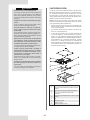 6
6
-
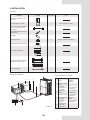 7
7
-
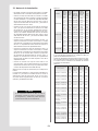 8
8
-
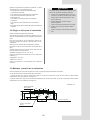 9
9
-
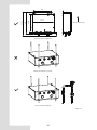 10
10
-
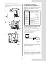 11
11
-
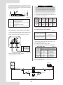 12
12
-
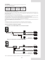 13
13
-
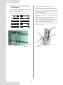 14
14
-
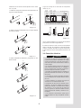 15
15
-
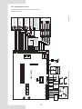 16
16
-
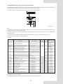 17
17
-
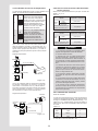 18
18
-
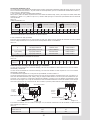 19
19
-
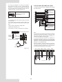 20
20
-
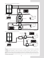 21
21
-
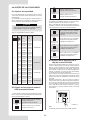 22
22
-
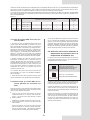 23
23
-
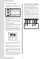 24
24
-
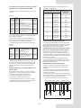 25
25
-
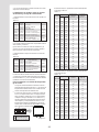 26
26
-
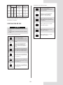 27
27
-
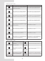 28
28
-
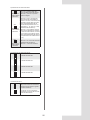 29
29
-
 30
30
-
 31
31
-
 32
32
-
 33
33
-
 34
34
-
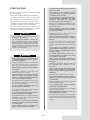 35
35
-
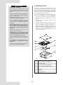 36
36
-
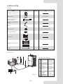 37
37
-
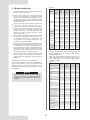 38
38
-
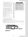 39
39
-
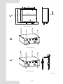 40
40
-
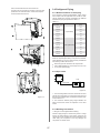 41
41
-
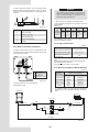 42
42
-
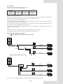 43
43
-
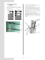 44
44
-
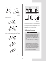 45
45
-
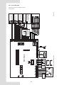 46
46
-
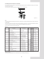 47
47
-
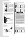 48
48
-
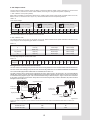 49
49
-
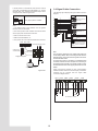 50
50
-
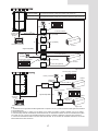 51
51
-
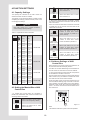 52
52
-
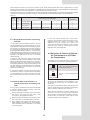 53
53
-
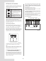 54
54
-
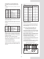 55
55
-
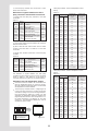 56
56
-
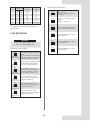 57
57
-
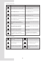 58
58
-
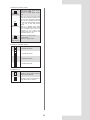 59
59
-
 60
60
-
 61
61
-
 62
62
-
 63
63
-
 64
64


HTW KIT AHUKZ Manual de usuario
- Tipo
- Manual de usuario
- Este manual también es adecuado para
En otros idiomas
- English: HTW KIT AHUKZ User manual
Otros documentos
-
LG PAHCMM000 Guía de instalación
-
LG PRLK594A0 Guía de instalación
-
LG PAHCNM000 Manual de usuario
-
LG AC Smart BACnet Guía de instalación
-
-
LG AMR003HNADV.AWGBLAT El manual del propietario
-
-
LG PACM5A000 Manual de usuario
-
-
LG PATX35A0E.ENCXLEU Guía de instalación