
P/NO : MFL69023103
www.lg.com
Asegúrese de leer las precauciones de seguridad antes de la instalación y uso, y
utilícelo correctamente.
Se ha diseñado para proteger la seguridad del instalador y el usuario y evitar daños
materiales, etc.
Tras leer el manual de usuario, guárdelo en un lugar donde pueda consultarlo en
cualquier momento.
MANUAL DE INSTALACIÓN/USUARIO
AIRE
ACONDICIONADO
AC Smart BACnet
PBACNA000
ESPAÑOL


i
ESPAÑOL
NOTAS EXPLICATIVAS
NOTAS EXPLICATIVAS
Copyrights
El contenido del Manual de usuario del modelo AC Smart BACnet está protegido por leyes de
copyright internacionales y la Ley de Protección de Programas Informáticos. El contenido de este
Manual de usuario y de los programas mencionados en el mismo solo podrán utilizarse bajo licencia
de LG Electronics, respetando estrictamente las estipulaciones del contrato de usuario.
Queda prohibida la reproducción y distribución, por cualquier medio, de copias de este Manual de
usuario o parte del mismo, sin la aprobación previa de LG Electronics.
Copyright © 2014 LG Electronics. Todos los derechos reservados.
Marcas comerciales registradas
AC Smart BACnet es una marca comercial registrada de LG Electronics. Todos los demás nombres
de empresas y productos son marcas comerciales de sus respectivos propietarios y se usan
únicamente con fines ilustrativos.

ii
ESPAÑOL
NOTAS EXPLICATIVAS
Características del producto
Servidor web integrado
Puede utilizar Internet Explorer para acceder a diverso contenido en línea sin necesidad de instalar
software adicional.
Además, puede utilizar la función de control de demanda para conectar AC Smart BACnet
directamente al controlador de demanda LG Electronics, y así controlar la potencia según sus
necesidades.
Interfaz controladora central sencilla
Podrá interconectar ACP IV / AC Smart BACnet con una controladora central sencilla para 16
habitaciones.
Interfaz de AC Manager IV
Puede conectar AC Smart BACnet con un AC Manager IV basado en ordenador para utilizar las
diversas funciones de AC Manager IV. También puede utilizar la función de programación, incluso
mientras el ordenador con AC Manager IV está apagado.

iii
ESPAÑOL
NOTAS EXPLICATIVAS
Cómo usar este manual
Lea este Manual de usuario en su totalidad antes de utilizar AC Smart BACnet. Guarde este manual
en un lugar de fácil acceso.
Notaciones usadas en este manual
• Los botones de control mostrados en el sistema se indican con texto en negrita entre corchetes ([ ]).
Ejemplo: [OK], [Save]
• Los títulos de opciones mostrados en el programa se indican con texto en negrita.
Ejemplo: Inicio, Programas
• Las pulsaciones de teclado que usa el sistema se indican con texto en negrita entre
paréntesis angulares (< >).
Ejemplo: <Esc>

iv
ESPAÑOL
MEMO

v
ESPAÑOL
ÍNDICE
1
PRECAUCIONES DE
SEGURIDAD
7
PREPARACIÓN
7 Descripción general de AC Smart
BACnet
7 Componentes
8 Especificaciones del producto
9 Características y funciones
11 Instalación y configuración
11 – Instalación
21 – Cómo configurar una función de
parada de emergencia
22 Método de introducción de
información
23
INICIO
23 Encendido/apagado de la pantalla
23 – Encendido de la pantalla
23 – Apagado de la pantalla
24 Reinicio
24 Inicio y cierre de sesión
25
LG’S AC Smart BACnet
AGREEMENT
27
FUNCTIONAL
SPECIFICATIONS
AC Smart BACnet
27 – Summary
27 – Configuration of Connection
28 – Objects - AC Smart BACnet /IP
46 – Objects (Modbus-TCP)
59 – Initialization at the Start Up
59 – Clock Setting
60 – Report Function
61
NOTES
61 BIBBs
61 – Data Sharing BIBBS
63 – Alarm and Event Management BIBBS
64 – Scheduling BIBBS
64 – Trending BIBBS
65 – Device Management BIBBS
66 – Device Management BIBBS
66 – Network Management BIBBS
68 Multi - state Input Object Type
68 – Multi - state Output Object Type
70 AC Smart BACnet Error Response
Table
70 – Error PDU
70 – Reject PDU
71 – Abort PDU
72
CONSEJO
72 Códigos de control
72 Códigos de error
72 – Error de dispositivo interior, ERV o
ERV DX, AWHP (Kit hidro), UTA
75 – Errores de unidad exterior
77 – Error MultiV 20 Hp, 30 Hp, 40 Hp,
79 – Errores del súper
81 – Errores del controlador central
82 Lista de comprobación previa al
contacto con el servicio de soporte
técnico
82 AVISO DE SOFTWARE DE
CÓDIGO ABIERTO
ÍNDICE

vi
ESPAÑOL
MEMO

1
ESPAÑOL
PRECAUCIONES DE SEGURIDAD
PRECAUCIONES DE SEGURIDAD
• Este producto debe instalarlo un instalador profesional de un centro de servicio autorizado
por LG.
• Los problemas derivados de la instalación por parte de una persona no autorizada serán
responsabilidad del usuario, y no estarán cubiertos por la garantía.
• Las siguientes advertencias de seguridad tienen como finalidad evitar peligros o daños
imprevistos.
• Este producto se ha diseñado para uso profesional, o para zonas fuera de hogares, y ha
superado la Prueba de interferencias electromagnéticas.
ADVERTENCIA
Puede resultar en lesiones graves o la muerte cuando se tienen en cuenta las instrucciones
PRECAUCIÓN
Puede resultar en lesiones leves o daños en el producto cuando las instrucciones son
ignoradas
ADVERTENCIA
instalación
y
Si desea reinstalar el producto, póngase en contacto con el distribuidor en el que compró
el producto, o con un centro de servicio, para solicitar el servicio de reinstalación.
- La instalación del producto por parte de una persona no autorizada podría provocar un incen-
dio, una descarga eléctrica, una explosión, lesiones o fallos de funcionamiento del producto.
y
No retuerza ni dañe el cable de alimentación.
- Podría provocar un incendio o descargas eléctricas.
y
Para los trabajos eléctricos, póngase en contacto con el distribuidor en el que compró el
producto o con un centro de servicio.
- Si una persona no autorizada realiza el desmontaje o la reparación podría producirse un incen-
dio o una descarga eléctrica.
y
Instale el producto en una zona protegida de la lluvia.
- Si accede agua al producto podrían producirse fallos de funcionamiento.
y
No instale el producto en una zona húmeda.
- Si el producto se humedece, podría presentar fallos de funcionamiento.

2
ESPAÑOL
PRECAUCIONES DE SEGURIDAD
y
Para la instalación del producto, póngase en contacto con el distribuidor en el que compró
el producto o con un centro de servicio.
- La instalación del producto por parte de una persona no autorizada podría provocar un incen-
dio, una descarga eléctrica, una explosión, lesiones o fallos de funcionamiento del producto.
y
Para los trabajos eléctricos, encargue a un electricista el trabajo pidiéndole que se base
en el manual de instalación y en el diagrama eléctrico especificado.
- El uso de un cable inadecuado o permitir que una persona no profesional realice los trabajos
eléctricos podrían provocar incendios o descargas eléctricas.
y
No coloque el producto cerca de fuentes de fuego.
- Si lo hace, el producto podría incendiarse.
y
Si el producto se instala en un hospital o en una estación base de comunicaciones, instale
equipos de protección suficientes contra el ruido.
- Si no lo hace, el producto podría funcionar incorrectamente o provocar que otros productos lo
hicieran.
y
Afiance la instalación del producto correctamente.
- Si el producto no se instala con firmeza, podría caerse o presentar fallos de funcionamiento.
y
Lea el manual detenidamente para instalar el producto de forma correcta.
- En caso contrario, una instalación incorrecta podría provocar un incendio o una descarga eléctrica.
y
A la hora de realizar el cableado del producto, no utilice un cable no convencional ni
extienda el cable hasta una longitud excesiva.
- Podría provocar un incendio o descargas eléctricas.
y
Instale correctamente el cable de alimentación y el cable de comunicaciones.
- Una instalación insegura podría provocar un incendio o una descarga eléctrica.
y
No conecte el cable de alimentación al terminal de comunicaciones.
- Esto podría provocar un incendio, una descarga eléctrica o fallos de funcionamiento del producto.
Uso
y
No coloque objetos pesados sobre el cable de alimentación.
- Podría provocar un incendio o descargas eléctricas.
y
No cambie ni realice extensiones arbitrarias del cable de alimentación.
- Podría provocar un incendio o descargas eléctricas.
y
Utilice el cable específico del producto.
- El uso de un cable no convencional no autorizado podría provocar un incendio o una descarga
eléctrica.
y
No utilice un dispositivo de calefacción cerca del cable de alimentación.
- Podría provocar un incendio o descargas eléctricas.
y
Asegúrese de que nunca entra agua al producto.
- Podrían producirse una descarga eléctrica o fallos de funcionamiento.
y
No coloque ningún recipiente con líquido sobre el producto.

3
ESPAÑOL
PRECAUCIONES DE SEGURIDAD
- El producto podría presentar fallos de funcionamiento.
y
No toque el producto con las manos mojadas.
- Podría provocar un incendio o descargas eléctricas.
y
Utilice componentes convencionales.
- El uso de un producto no autorizado podría provocar un incendio, una descarga eléctrica, una
explosión, lesiones o fallos de funcionamiento del producto.
y
Si se sumerge el producto en agua deberá ponerse en contacto con un centro de servicio.
- Podría provocar un incendio o descargas eléctricas.
y
No golpee el producto.
- El producto podría presentar fallos de funcionamiento.
y
No guarde ni utilice gases combustibles ni sustancias inflamables cerca del producto.
- Esto podría provocar un incendio o fallos de funcionamiento del producto.
y
No desmonte, repare ni modifique el producto de forma arbitraria.
- Podría provocar un incendio o descargas eléctricas.
y
Los niños y las personas de edad avanzada deberán utilizar el producto bajo la
supervisión de un tutor.
- Un uso descuidado del producto podría provocar un accidente o fallos de funcionamiento.
y
El tutor debe evitar que los niños accedan al producto.
- El producto podría sufrir daños o caerse, provocando lesiones a los niños.
y
Respete el rango de temperatura operativa especificado en este manual.
Si en el manual no se indica rango de temperatura operativa alguno, utilice el producto
entre 0 y 40 ºC (32 y 104 °F).
- Si se utiliza el producto fuera de este rango el producto podría sufrir daños importantes.
y
No pulse los interruptores ni los botones con objetos afilados.
- Podrían producirse una descarga eléctrica o fallos de funcionamiento.
y
No cablee el producto mientras se encuentra encendido.
- Podría provocar un incendio o descargas eléctricas.
y
Si el producto emite sonidos o genera olores diferentes, deje de utilizarlo.
- Podría provocar un incendio o descargas eléctricas.
y
No coloque objetos pesados sobre el producto.
- El producto podría presentar fallos de funcionamiento.
y
No rocíe agua sobre el producto ni lo utilice con un paño sumergido en agua.
- Podría provocar un incendio o descargas eléctricas.
y
No utilice el producto para la conservación de animales y plantas, instrumentos de
precisión, obras de arte ni con fines especializados.
- Podrían producirse daños materiales.
y
Deshágase del material de embalaje de forma segura.
- El material de embalaje podría provocar lesiones personales.

4
ESPAÑOL
PRECAUCIONES DE SEGURIDAD
PRECAUCIÓN
instalación
y
No instale el producto en una zona próxima a gas combustible.
- Podría provocar un incendio, una descarga eléctrica, una explosión, lesiones o fallos de fun-
cionamiento del producto.
y
Instale el producto correctamente en una zona capaz de resistir el peso del producto.
- De lo contrario, el producto podría caer y destruirse.
y
No utilice el producto en entornos con aceite, vapor o gas sulfúrico.
- Podría afectar al rendimiento del producto e incluso dañarlo.
y
Compruebe la capacidad de potencia nominal.
- Podría provocar un incendio o fallos de funcionamiento del producto.
y
Utilice el adaptador suministrado con el producto o el poder de un transformador de
AC 24 V 2 clases, dependiendo del modelo.
- Si se utiliza un adaptador no convencional el producto podría presentar fallos de funcionamien-
to. El adaptador no se incluye con el paquete AC Smart BACnet comercializado en los Estados
Unidos.
y
Tenga cuidado de no dejar caer el producto ni dañarlo al moverlo.
- El producto podría funcionar incorrectamente, o la persona podría sufrir una lesión.
y
Asegúrese de que el cable se encuentre correctamente conectado para evitar la
condensación, el agua o que insectos accedan al producto.
- Si accede una sustancia extraña al producto, podría provocar una descarga eléctrica o fallos de
funcionamiento del producto.

5
ESPAÑOL
PRECAUCIONES DE SEGURIDAD
Uso
y
Limpie el producto con un paño suave, pero no con un detergente con base disolvente.
- El uso de un detergente con base disolvente podría provocar un incendio o deformar el pro-
ducto.
y
No toque el panel utilizando un objeto puntiagudo o afilado.
- Podrían producirse una descarga eléctrica o fallos de funcionamiento.
y
No deje que el producto entre en contacto con sustancias metálicas.
- El producto podría presentar fallos de funcionamiento.
y
Durante los procesos de esterilización y desinfección deberá dejar de utilizar el producto.
- El producto podría funcionar de una forma anómala.
y
No toque el interior del producto.
- El producto podría presentar fallos de funcionamiento.
y
Compruebe el estado del producto después de no utilizarlo durante un periodo de tiempo
prolongado.
- Si el producto va a utilizarse durante un periodo de tiempo prolongado, el producto podría
funcionar incorrectamente y provocar lesiones al usuario.
y
No deje el producto cerca de un florero, una botella de agua ni ningún otro líquido.
- Podría provocar un incendio o descargas eléctricas.
y
Si el cristal líquido del producto se rompe, no permita que su piel, por ejemplo, la cara,
entre en contacto con el cristal.
- Podría sufrir lesiones o causar daños materiales.
y Selección del transformador:
- Seleccione un producto aislante que cumpla con las normativas IEC61558-2-6 y NEC Clase 2.
- De la misma forma, para la selección del transformador correspondiente deberá tener en cuenta
también el consumo energético combinado de los módulos, accesorios y dispositivos de campo.
Corriente del módulo principal: AC 24 V, 850 mA
- Si utiliza DC 12 V, utilice el adaptador incluido. El adaptador no se incluye con el paquete AC
Smart BACnet comercializado en los Estados Unidos.

6
ESPAÑOL
PRECAUCIONES DE SEGURIDAD
Dispositivo de Clase A
NOTA
Este equipo ha sido probado y ha demostrado cumplir con los límites para un dispositivo digital
Clase A, conforme a la parte 15 de las normas FCC.
Estos límites están diseñados para proporcionar una protección razonable contra las
interferencias perjudiciales cuando el equipo se utiliza en un entorno comercial.
Este equipo genera, utiliza y puede irradiar energía de radiofrecuencia y, si no se instala y
utiliza de acuerdo con el manual de instrucciones, puede causar interferencias perjudiciales
en las comunicaciones. El funcionamiento de este equipo en un área residencial puede
causar interferencias perjudiciales interferencias, en cuyo caso el usuario deberá corregir la
interferencia a su propio costo.
PRECAUCIÓN
Los cambios o modificaciones no aprobados expresamente por el fabricante responsable del
cumplimiento podrían anular la autoridad del usuario para operar el equipo.
Cómo desechar aparatos eléctricos y electrónicos obsoletos
1. Si en un producto aparece el símbolo de un contenedor de basura
tachado, significa que éste se acoge a la Directiva 2002/96/EC.
2. Todos los aparatos eléctricos o electrónicos se deben desechar
aparte del servicio municipal de recogida de basuras, a través de
los puntos de recogida designados por el gobierno o las autoridades
locales.
3. La correcta recogida y tratamiento de los aparatos inservibles
contribuye a evitar posibles riesgos negativos para el medio ambiente
y la salud pública.
4. Para obtener más información sobre cómo desechar los aparatos
inservibles, póngase en contacto con su ayuntamiento, el servicio de
recogida de basuras o el establecimiento donde adquirió el producto.

7
ESPAÑOL
PREPARACIÓN
PREPARACIÓN
Este apartado contiene información sobre los componentes de AC Smart BACnet, cómo instalarlos
y configurarlos, y otra información necesaria para utilizar el producto.
Descripción general de AC Smart BACnet
AC Smart BACnet es un controlador central instalado en el centro de gestión del edificio, o en la
oficina de administración de una institución educativa, para supervisar o controlar desde su pantalla
táctil las unidades interiores, los ERV, DI/DO, DOKIT, AWHP, UTA y I/O Módulos instalados en
el interior del edificio. AC Smart BACnet es capaz de gestionar, de forma tanto colectiva como
independiente, las unidades interiores, los ERV, DI/DO, DOKIT, AWHP y UTA de hasta 128 salas.
(O la unidades interiores, ERV, DI/DO, DOKIT, AWHP y UTA para hasta 64 dispositivos y 9 I/O
Módulos)
Componentes
La caja del paquete incluye los siguientes componentes. Abra la caja y asegúrese de que incluye
todos los componentes.
AC Smart BACnet
Cable de corriente
P/NO : MFL69023103
www.lg.com
Asegúrese de leer las precauciones de seguridad antes de la instalación y uso, y
utilícelo correctamente.
Se ha diseñado para proteger la seguridad del instalador y el usuario y evitar daños
materiales, etc.
Tras leer el manual de usuario, guárdelo en un lugar donde pueda consultarlo en
cualquier momento.
MANUAL DE INSTALACIÓN/USUARIO
AIRE
ACONDICIONADO
AC Smart BACnet
PBACNA000
ESPAÑOL
Guía rápidaAdaptador de corrienteAC Smart BACnet
Manual de usuario
El adaptador no se incluye con el paquete AC Smart BACnet comercializado en los Estados Unidos.

8
ESPAÑOL
PREPARACIÓN
NOTA
Las ilustraciones de los componentes y de los productos opcionales adquiridos mostrados
podrían ser diferentes de los componentes y productos reales.
Especificaciones del producto
Las especificaciones del producto AC Smart BACnet son las siguientes.
Elemento Especificaciones
CPU
PCIMX5150D
y Núcleo ARM Cortex A8™
y 800 MHz
MEMORIA 128 × 4 MB (DDR2 SDRAM)
Almacenamiento 4 GB (INAND FLASH)
LCD LCD TFT WSVGA (1024 × 600) de 10,2 pulgadas
Altavoz Monoaural de 300 mW
RS485 2 puertos
USB/SD
y MICRO USB: 1 (para la memoria USB externa, para tareas de
servicio)
y MINI USB: 1
y Tarjeta SD: 1
DI 2 puertos
DO 2 puertos
Pantalla táctil Panel táctil tipo C
Tecla de botón
Menos de 9 segundos (ENCENDIDO/APAGADO DEL LCD), 10 segundos
(RESTABLECIMIENTO DEL SISTEMA)
ALIMENTACIÓN DC 12 V (3,33 A), AC 24 V
SO Linux

9
ESPAÑOL
PREPARACIÓN
Características y funciones
A continuación se muestran las características y funciones de AC Smart BACnet.
⑦ ⑧
⑪⑩⑨
①
③② ⑥④ ⑤
<Parte delantera>
<Parte inferior>
<Parte trasera>
Número Elemento Descripción
①
Pantalla táctil
y Panel de control LCD de 10,2 pulgadas
y Pantalla de control e información de AC Smart
BACnet
②
Ranura de memoria SD Ranura de memoria para tarjetas SD
③
Puerto DO Puerto DO de 2 canales
④
Puerto DI Puerto DI de 2 canales
⑤
Puerto 485
Puerto 485 2CH (CH1: AHU y dispositivo de
comunicación MODBUS, CH2: dispositivos diferentes
de la AHU y dispositivo de comunicación MODBUS)
⑥
Puerto de entrada DC 12 V Puerto de entrada de alimentación DC 12 V
⑦
Puerto LAN
Puerto de cable LAN para conexión Ethernet
(100Mbps/10Mbps)
⑧
Puerto de entrada AC 24 V Puerto de entrada de alimentación AC 24 V
⑨
Puerto micro USB
(para servicio)
Puerto para actualización de software y almacenar
planos de plantas, informes, estadísticas, etc.
(Se necesita cable para conectar pendrives USB,
compatibles o USB 2.0 o posterior)
⑩
Puerto mini USB Puerto PC para software de depuración

10
ESPAÑOL
PREPARACIÓN
Número Elemento Descripción
⑪
Encendido/apagado
y Mantener pulsado durante menos de 10 segundos
para controlar la retroiluminación LCD de AC Smart
BACnet.
y Mantener pulsado durante 10 segundos o más
para restablecer AC Smart BACnet.
y Si no va a utilizar AC Smart BACnet durante un
periodo de tiempo prolongado, le recomendamos
que apague el producto para prolongar la vida útil
de la retroiluminación del panel LCD.

11
ESPAÑOL
PREPARACIÓN
Instalación y configuración
En estos capítulos se explica cómo instalar y configurar AC Smart BACnet.
Instalación
Para utilizar AC Smart BACnet, cree un entorno en el que AC Smart BACnet pueda establecer
comunicación con dispositivos como la unidad interior, el ERV, DI/DO, DOKIT, AWHP, UTA y I/O
Módulos. Utilice AC Smart BACnet para registrar estos dispositivos.
AC Smart BACnet debe instalarse siguiendo el orden indicado a continuación:
PASO 1. Revise el entorno de instalación y configure la dirección del
dispositivo.
Revise la configuración de red comparándolos con los dispositivos
interconectados antes de instalar AC Smart BACnet y asignar una dirección
única para cada dispositivo conectado.
PASO 2. Conecte el PI485 al AC Smart BACnet.
Utilice un cable RS485 para conectar el PI485 al AC Smart BACnet.
PASO 3. Inicie sesión y registre el dispositivo.
Inicie sesión en AC Smart BACnet y registre los dispositivos que tengan establecida
la dirección.
PRECAUCIÓN
La instalación del AC Smart BACnet debe realizarla un profesional. Asegúrese de solicitar la
instalación a un ingeniero cualificado. Si tiene algún tipo de pregunta o solicitud relativa al
proceso de instalación, póngase en contacto con un instalador profesional de un centro de
servicio LG autorizado o con LG Electronics.

12
ESPAÑOL
PREPARACIÓN
Revise el entorno de instalación y configure la dirección del dispositivo
AC Smart BACnet puede conectar hasta 128 dispositivos (incluidas las unidades internas, los ERV,
DI/DO, DOKIT, AWHP, UTA) o 64 dispositivos (incluidas las unidades internas, los ERV, DI/DO,
DOKIT, AWHP, UTA) y 9 I/O Módulos.
A continuación se muestra un ejemplo de conexión del AC Smart BACnet con este tipo de
dispositivos.
Cantidad de
I/O módulo
Cantidad de
dispositivo
0 128
1 121
2 114
3 107
4 100
5 93
6 86
7 79
8 72
9 64
Quantity of
Device
Quantity of
I/O Module
128
64
9
* Dispositivos : Unidades interiores, ERV, DI/DO, DOKIT, AWHP, UTA
Cantidad de
dispositivo
Cantidad de
I/O módulo

13
ESPAÑOL
PREPARACIÓN
El AC Smart BACnet se conecta con el PI485 y utiliza la conexión RS485 para comunicar e
intercambiar información. Asigne direcciones únicas a estos dispositivos (unidades internas,
ERV, DI/DO, DOKIT, AWHP, UTA, I/O Módulos) que se conectarán con el AC Smart BACnet. Las
direcciones son números hexadecimales, que pueden elegirse desde 00 hasta FF.
...
AC Smart BACnet
Unidades exteriores
Indicador de distribución
de alimentación
medidor de
vatios por hora
ERV
DI/DO, DOKIT
AWHP
AHU
Dispositivos
interiores 1
Dirección de
configuración: 01
Dirección de
configuración: 11
Dirección de
configuración: 21
Dirección de
configuración: 31
Dirección de
configuración: 41
Dirección de
configuración: 02
Dirección de
configuración: 03
Dispositivos
interiores 2
Dispositivos
interiores 3

14
ESPAÑOL
PREPARACIÓN
NOTA
y
La distancia de comunicación permitida máxima garantizada por LG Electronics es de 1 000 m.
Esto supone que la distancia máxima entre el AC Smart BACnet y el dispositivo más alejado no
debe ser superior a los 1 000 m. Se recomienda utilizar un cable de comunicación de 0,75
㎟
cuadrados o superior.
y
No es posible asignar direcciones idénticas entre dispositivos del mismo tipo para unidades
interiores, ERV, DI/DO, DOKIT, AWHP, UTA y I/O Módulos. Asigne direcciones diferentes para
los dispositivos del mismo tiempo. (una unidad interior y un DOKIT no pueden utilizar la misma
dirección.)
y
Cada dispositivo que se puede utilizar con PDI debe establecerse en una dirección única
cuando se conecta con PDI. Para obtener más información acerca de los dispositivos se
puede utilizar con PDI, consulte el manual de PDI.
y
I/O módulo de conexión, configuración de la dirección no debe ser 00 porque 00 se utiliza
para difundir en la comunicación MODBUS.

15
ESPAÑOL
PREPARACIÓN
Conexión RS485 del AC Smart BACnet
Un AC Smart BACnet puede tener un máximo de 128 unidades interiores. Si van a conectarse
muchas unidades exteriores, conéctelas a un bus. De lo contrario, AC Smart BACnet podría
presentar fallos de funcionamiento.
<Buen ejemplo: conexión formato BUS RS485> < Mal ejemplo: conexión RS485 con formato
ESTRELLA>
NOTA
Número máximo de nodos que pueden conectarse a la línea de comunicaciones RS485.
y
Multi V
Pueden conectarse un máximo 16 nodos a 1 línea RS485.
y
Múltiple/Sencillo
Pueden conectarse un máximo 32 nodos a 1 línea RS485.
y
ERV
Pueden conectarse un máximo 32 nodos a 1 línea RS485.

16
ESPAÑOL
PREPARACIÓN
Conecte al AC Smart BACnet
Puede instalar AC Smart BACnet y sus cables de la forma siguiente.
1. Elija el lugar de instalación de AC Smart BACnet.
• Antes de fijar el AC Smart BACnet, asegúrese de que el espacio resulta apto para instalar AC
Smart BACnet, un cable RS485, un cable de alimentación y un cable UTP.
2. Fije el panel trasero del AC Smart BACnet a la pared en la que se encuentra el cable RS485.
3. Despliegue el cable RS485 desde la parte superior del panel trasero.

17
ESPAÑOL
PREPARACIÓN
4. Conecte el cable RS485, situado detrás de AC Smart BACnet, al terminal RS485..
AB
AHU
AB
(RS485)
ODU
PRECAUCIÓN
El cable RS485 tiene polaridad, por lo que deberá respetar la polaridad a la hora de realizar
la conexión de los cables.
5. Para poder usar las funciones de red (transmisión de correos electrónicos y control web)
proporcionadas por AC Smart BACnet deberá conectar un cable UTP al puerto LAN situado en
la parte trasera del AC Smart BACnet.

18
ESPAÑOL
PREPARACIÓN
6. Conecte la alimentación.
• Para los modelos globales.
- En la parte trasera de AC Smart BACnet, conecte el adaptador de alimentación al conec-
tor de alimentación.
El adaptador no se incluye con el paquete AC Smart BACnet comercializado en los Estados
Unidos.
NOTA
Puede colgar el cable de alimentación del gancho de suspensión situado debajo del
conector de alimentación.

19
ESPAÑOL
PREPARACIÓN
• Para los modelos US
- En la parte inferior de AC Smart BACnet, conecte el cable de alimentación al conector de
alimentación.
NOTA
En algunos países, a excepción de los Estados Unidos, podrá conectar la alimentación de
DC 12 V al AC Smart BACnet utilizando el adaptador incluido. En caso de ser necesario,
conecte la alimentación de AC 24 V al AC Smart BACnet.

20
ESPAÑOL
PREPARACIÓN
7. Tras fijar en gancho de la parte superior del cuerpo principal a la parte superior del panel trasero
instalado en la pared, empuje hacia delante la parte superior del cuerpo principal hasta que se
active la señal HOOK (GANCHO).
PRECAUCIÓN
Atornille 2 puntos desde la parte inferior de la unidad para evitar caídas.
NOTA
Descomposición del producto
Tras separar los dos tornillos de la parte inferior del cuerpo, tire ligeramente del mismo con
la ayuda de un destornillador plano y eleve el cuerpo para desmontar el producto.
8. Conecte el cable de alimentación del adaptador de alimentación al enchufe.

21
ESPAÑOL
PREPARACIÓN
Cómo configurar una función de parada de emergencia
El AC Smart BACnet está equipado con una función de parada de emergencia que detiene el
funcionamiento de todos los dispositivos conectados (unidad interior, ventilador, DOKIT, AWHP y
AHU) si se produce una situación de emergencia en el interior del edificio. Cuando el sensor detecta
una situación de emergencia y transmite una señal de encendido al Puerto DI 1 del AC Smart
BACnet, todos los dispositivos conectados al AC Smart BACnet dejan de funcionar.
Puede usar la función de parada de emergencia si conecta el sensor de detección de movimientos
externos al Puerto DI 1 o el terminal conectado, que funciona por contacto eléctrico sin
alimentación, en la parte trasera del AC Smart BACnet.
PRECAUCIÓN
El Puerto DI 1 siempre se mantendrá abierto, excepto en casos de emergencia.

22
ESPAÑOL
PREPARACIÓN
Método de introducción de información
Toque el recuadro de introducción de información del AC Smart BACnet y aparecerá un panel táctil
en la parte inferior del panel. Utilice el teclado táctil para introducir la información.

23
ESPAÑOL
INICIO
INICIO
En este apartado se explica cómo conectar el sistema y registrar dispositivos para proceder a la
configuración del entorno (antes de usar AC Smart BACnet).
Encendido/apagado de la pantalla
A continuación se explica cómo encender y apagar la pantalla de AC Smart BACnet.
Encendido de la pantalla
La pantalla se enciende de la siguiente forma.
1. Pulse el botón de encendido y apagado situado en la parte inferior de la unidad.
• La pantalla se encenderá.
Apagado de la pantalla
La pantalla se apaga de la siguiente forma.
1. Pulse brevemente el botón de encendido y apagado situado en la parte inferior de la unidad.
• La pantalla se apagará.
NOTA
Si no va a utilizar AC Smart BACnet durante un periodo de tiempo prolongado, le
recomendamos que apague el producto para prolongar la vida útil de la retroiluminación del
panel LCD.

24
ESPAÑOL
INICIO
Reinicio
Podrá reiniciar el dispositivo de la forma siguiente.
1. Pulse el botón de encendido y apagado situado en la parte inferior de la unidad durante 10
segundos o más.
• El dispositivo se reiniciará.
Inicio y cierre de sesión
A continuación se explica cómo iniciar y cerrar sesión en AC Smart BACnet.
AC Smart BACnet está, se puede controlar no sólo el equipo, sino también Web. Si introduce la
dirección IP de la unidad AC Smart BACnet en la barra de direcciones de Internet sin necesidad de
instalar otro programa, el programa de control central AC Smart BACnet calidad, servidor Web se ha
ejecutado de forma automática, para utilizar la funcionalidad de los diversos contenidos puedo.
El Manual, que explicará a los equipos de AC Smart BACnet estándar.
NOTA
y
Necesitará el Adobe Flash Player se instalará para el control Web.
(Especificación recomendada : Adobe Flash Player 11)
y
Caracteres especiales (^), (‘) y(,) no están disponibles.

25
ESPAÑOL
LG’S AC Smart BACnet AGREEMENT
LG’S AC Smart BACnet AGREE-
MENT
JMT (Joint Matching Test)
This is necessary for every independent BMS.
The case where a JMT is not necessary is where previously a successful JMT has been carried out
and the BMS system has not been updated by software or hardware changes. In the case that the BMS
has updated their system by either changes, a following JMT will be required.
AC Smart BACnet Diagnosis
Use of LG’s AC Smart BACnet setup-tool is for confirming the operation/state of connected A/C units
& address ID’s, prior to connection with the BMS system.
BMS Engineering
Creating of the Points. This is NOT to be done by LG since it is directly related to the BMS side. The
BMS engineer is to carry out the engineering of the Point, however LG is responsible for providing the
method of how the Points are calculated.
Commission
First step, only using LG’s AC Smart BACnet , without connecting BMS. This is to be carried out by LG
engineering staff with the use of the AC Smart BACnet set up tool.
Discrepancy of operation of Gateway by BMS
In the case that the BMS maker feels that the AC Smart BACnet is not functioning correctly via the
BACnet Protocol, a test with the use of LG’s AC Smart BACnet Client software can confirm this. (This
test is generally not required)

26
ESPAÑOL
LG’S AC Smart BACnet AGREEMENT
Notes
After the LG's AC Smart BACnet agreement part, please consult with the experts of BMS.
PQNFB17C
Hub
BACnet
LG-NET
AC Smart BACnet
Diagnosis
1. Creating of indoor and vent points.
2. Test of all units and operations.
BMS Engineering SideLG Engineering Side

27
ESPAÑOL
FUNCTIONAL SPECIFICATIONS AC Smart BACnet
FUNCTIONAL SPECIFICATIONS
AC Smart BACnet
Summary
The AC Smart BACnet , in response to the requests from the BMS (Building management system
which supports BACnet-ANSI/ASHRAE135 protocol), status information of A/C/vent that are
connected to the AC Smart BACnet ’s internal LG-NET will be sent in BACnet service form, and
BACnet client provides a function that transmits control command to the A/C/vent system.
Configuration of Connection
A BACnet client that supports BACnet-ANSI/ASHRAE135 protocol allows direct connection via
generally used HUBs or Ethernet. The image of its connection configuration is as shown below.
PQNFB17C
AC Smart
BACnet

28
ESPAÑOL
FUNCTIONAL SPECIFICATIONS AC Smart BACnet
Objects - AC Smart BACnet /IP
BACnet Point List : Indoor Unit
One indoor unit has a Point List as follows.
Some of IDU Points may not be supported depending on the product.
Point
No.
Control/monitoring
Object Name
(XXX : Unit address)
Object
Type
Unit
Inactive Active
Text-0 Text-1
Text-2 Text-3 Text-4 Text-5
1 ON/OFF (Setting)
StartStopCommand_
XXX
BO Stop Start
2 ON/OFF (Status) StartStopStatus_XXX BI Stop Run
3 Lock (Setting) LockCommand_XXX BO Permit Prohibit
4 Lock (Status) LockStatus_XXX BI Permit Prohibit
5 Filter Sign Filter Sign_XXX BI Off On
6 Filter Sign Reset
Filter Sign Reset_
XXX
BV - Reset
7 Operation Mode (Setting) ModeCommand_XXX MO Cool Dry Fan Auto Heat
8 Operation Mode (Status) ModeStatus_XXX MI Cool Dry Fan Auto Heat
9 Swing (Setting)
SwingCommand_
XXX
BO Stop Run
10 Swing (Status) SwingStatus_XXX BI Stop Run
11 Fan Speed (Setting)
FanSpeedCommand_
XXX
MO Low Middle High Auto
12 Fan Speed (Status)
FanSpeedStatus_
XXX
MI Low Middle High Auto
13 Set Room Temperature SetRoomTemp_X X X AV °C
14 Room Temperature RoomTemp_XXX AI °C
15 Alarm Alarm_XXX BI Normal Abnormal

29
ESPAÑOL
FUNCTIONAL SPECIFICATIONS AC Smart BACnet
Point
No.
Control/monitoring
Object Name
(XXX : Unit address)
Object
Type
Unit
Inactive Active
Text-0 Text-1 Text-2 Text-3 Text-4 Text-5
16 Error Code MalfunctionCode_XXX Reference LG Original Error Code
17 - - -
18 - - -
19 Set Temperature Status SetTempStatus_XXX AI °C
20 Power Distribution AccumPowerStatus_XXX AI Wattage values (Unit : 100Watt)
27
Set Upper Temperature
Setting
SetUpperTempCommand_
XXX
AV °C
28
Set Lower Temperature
Setting
SetLowerTempCommand_
XXX
AI °C
29
Set Upper Temperature
Status
SetUpperTempStatus_XXX AI °C
30
Set Lower Temperature
Status
SetLowerTempStatus_XXX AI °C
31 Mode Lock Setting ModeLockCommand_XXX BO Permit Prohibit
32 Mode Lock Status ModeLockStatus_XXX BI Permit Prohibit
33 Fan Lock Setting Fan LockCommand_XXX BO Permit Prohibit
34 Fan Lock Status FanLockStatus_XXX BI Permit Prohibit

30
ESPAÑOL
FUNCTIONAL SPECIFICATIONS AC Smart BACnet
Point
No.
Control/monitoring
Object Name
(XXX : Unit address)
Object
Type
Unit
Inactive Active
Text-0 Text-1 Text-2 Text-3 Text-4 Text-5
35
Occupancy (Setting)
OccupancyCommand_XXX
BO
Unoccupied Occupied
36
Occupancy (Status)
OccupancyStatus_XXX
BI
Unoccupied Occupied
37
2Set Cooling Set Temperature (Setting)
2SetCoolingTempCommand_XXX
AV °C
38
2Set Cooling Set Temperature (Status)
2SetCoolingTempStatus_XXX
AI °C
39
2Set Heating Set Temperature (Setting)
2SetHeatingTempCommand_XXX
AV °C
40
2Set Heating Set Temperature (Status)
2SetHeatingTempStatus_XXX
AI °C
41
2Set Cooling Upper Temperature
(Setting)
2SetCoolingUpperLimitCommand_
XXX
AV °C
42
2Set Cooling Upper Temperature (Status)
2SetCoolingUpperLimitStatus_XXX
AI °C
43
2Set Heating Upper Temperature
(Setting)
2SetHeatingUpperLimitCommand_
XXX
AV °C
44
2Set Heating Upper Temperature (Status)
2SetHeatingUpperLimitStatus_XXX
AI °C
45
2Set Cooling Lower Temperature
(Setting)
2SetCoolingLowerLimitCommand_
XXX
AV °C
46
2Set Cooling Lower Temperature (Status)
2SetCoolingLowerLimitStatus_XXX
AI °C
47
2Set Heating Lower Temperature
(Setting)
2SetHeatingLowerLimitCommand_
XXX
AV °C
48
2Set Heating Lower Temperature (Status)
2SetHeatingLowerLimitStatus_XXX
AI °C
49
Thermo Status (Status)
ThermoStatus_XXX
BI
Off On
35 ~ 49 points are effective, in case 2Set Auto Mode of environment setting is enabled.

31
ESPAÑOL
FUNCTIONAL SPECIFICATIONS AC Smart BACnet
Remarks
• Point NO. 1
1. The command executed is transmitted to the A/C regardless of the status of the A/C.
2. Present_Value property will not be used if a property has never been set in the past.
• Point NO. 2
1. If there is an operation error, the Present_Value property will be set to ACTIVE regardless of
whether the A/C is in operation or not.
• Point NO. 7
1. The Present_Value property will be set to “1: Cool” as the default value if property has never
been set in the past.
2. The air conditioner will ignore the command to an object that does not have right to select
operation mode. Therefore, the controlled/monitored system must not use this object for the air
conditioner without the right to select operation mode.
• Point NO. 11
1. The A/C will disregard the command which the object which can’t select the operation mode.
Therefore, controlled/monitored system shouldn’t use the object which can’t select the operation
mode.
• Point NO. 12
1. Present_value property will be set to “1:Low” as the default result if the property has not been set
in the past.
• Point NO. 13
1. This unit is for indoor units only, and the approximate set temperature range is 18 ~ 35 °C.
2. When COV registration is made, the COV will be reported the moment a temperature change of
at least 0.5 °C is detected.
• Point NO. 14/ 19
1. This object is for indoor units only, and reports the room temperature data measured by the
indoor units.
• Point NO. 16
1. This object’s error code descriptions should be referred to the corresponding table at the
“Reference LG original Error Code”.
• Point NO. 35 ~ 49
1. This objects are effective, in case 2Set Auto Mode of environment setting is enabled.

32
ESPAÑOL
FUNCTIONAL SPECIFICATIONS AC Smart BACnet
BACnet Point List : Ventilation
One Ventilation unit has a Point List as follows.
Point
No.
Control/monitoring
Object Name
(XXX : ventilation
address)
Object
Type
Unit
Inactive Active
Text-0 Text-1 Text-2 Text-3 Text-4 Text-5
1 ON/OFF (Setting)
StartStopCommand_
XXX
BO Stop Start
2 ON/OFF (Status) StartStopStatus_XXX BI Stop Run
3 Lock (Setting) LockCommand_XXX BO Permit Prohibit
4 Lock (Status) LockStatus_XXX BI Permit Prohibit
5 Filter Sign Filter Sign_XXX BI Off On
6 Filter Sign Reset
Filter Sign Reset_
XXX
BV - Reset
7
Operation Mode
(Setting)
ModeCommand_XXX MO
Heat
Exchange
Auto Normal
8 Operation Mode (Status) ModeStatus_XXX MI
Heat
Exchange
Auto Normal
9 - -
10 - -
11 Fan Speed (Setting)
FanSpeedCommand_
XXX
MO Low High
Super
High
Auto
12 Fan Speed (Status)
FanSpeedStatus_
XXX
MI Low High
Super
High
Auto
13 - -
14 - -
15 Alarm Alarm_XXX BI Off On

33
ESPAÑOL
FUNCTIONAL SPECIFICATIONS AC Smart BACnet
Point
No.
Control/monitoring
Object Name
(XXX : ventilation
address)
Object
Type
Unit
Inactive Active
Text-0 Text-1 Text-2 Text-3 Text-4 Text-5
16 Error Code MalfunctionCode_XXX AI Reference LG Original Error Code
17 User Mode(Setting)
UserModeCommand_
XXX
MO
Quick
Fresh
Energy
Saving
Heater
18 User Mode(Status) UserModeStatus_XXX MI
Quick
Fresh
Energy
Saving
Heater
19 °C
20 - - -
21
AC Operation Mode
(setting)
HrvModeCommand_XXX MO Cool Auto Heat
22
AC Operation Mode
(status)
HrvModeStatus_XXX MI Cool Auto Heat
23 AC ON/OFF (setting)
HrvStartStopCommand_
XXX
BO Stop Run
24 AC ON/OFF (status) HrvStartStopStatus_XXX BI Stop Run
25 AC Humidify (setting)
HrvHumidifyCommand_
XXX
BO Off On
26 AC Humidify (status) HrvHumidifyStatus_XXX BI Off On

34
ESPAÑOL
FUNCTIONAL SPECIFICATIONS AC Smart BACnet
Remarks
• Point NO. 1
1. The command executed is transmitted to the A/C regardless of the status of the A/C.
2. Present_Value property will not be used if a property has never been set in the past.
• Point NO. 2
1. If there is an operation error, the Present_Value property will be set to ACTIVE regardless of
whether the A/C is in operation or not.
• Point NO. 5
1. This object supports the Intrinsic Reporting function. When the Present_Value property changes,
the corresponding Event will be transmitted if the Event has been registered.
• Point NO. 6
1. During a read operation of the Present_Value property, the Fliter Limit Sign Reset will be always
the same value as the Filter Limit Sign object.
2. Only if INACTIVE is written to the Present_Value property during a write operation, the filter sign
information resets ON signs and nothing will be executed even if ACTIVE is written.
3. This object supports the Intrinsic Reporting function. When the Present_Value property changes,
the corresponding Event will be transmitted if the Event has been registered.
• Point NO. 7
1. The Present_Value property will be set to “1: Cool” as the default value if property has never
been set in the past.
2. The air conditioner will ignore the command to an object that does not have right to select
operation mode. Therefore, the controlled/monitored system must not use this object for the air
conditioner without the right to select operation mode.
• Point NO. 11
1. The A/C will disregard the command which the object which can’t select the operation mode.
Therefore, controlled/monitored system shouldn’t use the object which can’t select the operation
mode.
• Point NO. 12
1. Present_value property will be set to “1:Low” as the default result if the property has not been set
in the past.
• Point NO. 16
1. This object’s error code descriptions should be referred to the corresponding table at the
“Reference LG original Error Code”.
• Point NO. 17
1. Th is object is for vent only, and will not apply if the property has not been set in the past.
• Point NO. 18
1. This object is for vent only, and will not apply if the property has not been in the past.

35
ESPAÑOL
FUNCTIONAL SPECIFICATIONS AC Smart BACnet
BACnet Point List : Ventilation
One Ventilation unit has a Point List as follows.
Point
No.
Control/
monitoring
Object Name
(XXX : AHU address)
Object
Type
Unit
Inactive Active
Text-0 Text-1 Tex t-2 Text-3 Text- 4 Text-5
1 ON/OFF (Setting) StartStopCommand_XXX BO Stop Run
2 ON/OFF (Status) StartStopStatus_XXX BI Stop Run
3 Lock (Setting) LockCommand_XXX BO Permit Prohibit
4 Lock (Status) LockStatus_XXX BI Permit Prohibit
5 Filter Sign Filter Sign_XXX BI Off On
6 Filter Sign Reset Filter Sign Reset_XXX BV - Reset
7
Operation Mode
(Setting)
ModeCommand_XXX MO Cool Dry Fan Heat
8
Operation Mode
(Status)
ModeStatus_XXX MI Cool Dry Fan Heat
9 - -
10 - -
11 - -
12 - -
13
Set Room
Temperature
SetRoomTemp_XXX AV °C
14
Room
Temperature
RoomTemp_XXX AI °C
15 Alarm Alarm_XXX BI Normal Abnormal
16 Error Code MalfunctionCode_XXX AI Reference LG Original Error Code

36
ESPAÑOL
FUNCTIONAL SPECIFICATIONS AC Smart BACnet
Point
No.
Control/monitoring
Object Name
(XXX : AHU address)
Object
Type
Unit
Inactive Active
Text-0 Text-1 Text-2 Text-3 Text-4 Text-5
17 - -
18 - -
19 Set Temperature (Status) SetTempStatus_XXX AI °C
20 Emergency Sensor (Setting)
EmergencySensorCommand_
XXX
BO
Stop
Run
21 Emergency Sensor (Status)
EmergencySensorStatus_
XXX
BI
Stop
Run
22 Set Humidify (Setting) SetHumidifyCommand_XXX AV 40~60
23 Set Humidify (Status) SetHumidifyStatus_XXX AI 40~60
24 Humidify (Setting) HumidifyCommand_XXX BO
Stop
Run
25 Humidify (Status) HumidifyStatus_XXX BI
Stop
Run
26 Auto Ventilation (Setting) AutoVentilCommand_XXX BO
Stop
Run
27 Auto Ventilation (Status) AutoVentilStatus_XXX BI
Stop
Run
28 Supply Temperature (Status) SupplyTempStatus_ X X X AI
-127~127
29 Outdoor Temperature (Status) OutdoorTempStatus_XXX AI
-127~127
30 Mix Temperature (Status) MixTempStatus_ XXX AI
-127~127
31 Supply Humidity (Status) SuppyHumidifyStatus_XXX AI 30~90
32 Outdoor Humidity (Status) OutdoorHumidifyStatus_XXX AI 30~90
33 Ventilation Humidity (Status) VentilHumidifyStatus_XXX AI 30~90
34 CO
2
Value (Status) CO2ValueStatus_XXX AI
0~255 (Real Value = Value*10, Example : In case Value is
20, CO
2
is 20*10=200ppm)
35 Humidify Unit (Status) HumidifyUnitStatus_XXX BI
Stop
Run
36 Heater Unit (Status) HeaterUnitStatus_XXX BI
Stop
Run

37
ESPAÑOL
FUNCTIONAL SPECIFICATIONS AC Smart BACnet
Point
No.
Control/
monitoring
Object Name
(XXX : AHU address)
Object
Type
Unit
Inactive Active
Text-0 Text-1 Text-2 Text-3 Text-4 Text-5
37
Ventilation FAN
(Status)
VentilFANStatus_XXX BI
Stop Run
38
Supply FAN
(Status)
SupplyFANStatus_XXX BI
Stop Run
39
Current OA
Damper (Status)
CurOADamperStatus_XXX AI 0~90
40
Current EA
Damper (Status)
CurEADamperStatus_XXX AI 0~90
41
Current MIX
Damper (Status)
CurMixDamperStatus_XXX AI 0~90
42
Cool OA Damper
(Setting)
OADamperCoolCommand_
XXX
AV 0~90
43
Cool OA Damper
(Status)
OADamperCoolStatus_XXX AI 0~90
44
Cool EA Damper
(Setting)
EADamperCoolCommand_
XXX
AV 0~90
45
Cool EA Damper
(Status)
EADamperCoolStatus_XXX AI 0~90
46
Cool MIX Damper
(Setting)
MixDamperCoolCommand_
XXX
AV 0~90
47
Cool MIX Damper
(Status)
MixDamperCoolStatus_XXX AI 0~90
48
Heat OA Damper
(Setting)
OADamperHeatCommand_
XXX
AV 0~90
Point
No.
Control/monitoring
Object Name
(XXX : AHU address)
Object
Type
Unit
Inactive Active
Text-0 Text-1 Text-2 Text-3 Text-4 Text-5
17 - -
18 - -
19 Set Temperature (Status) SetTempStatus_XXX AI °C
20 Emergency Sensor (Setting)
EmergencySensorCommand_
XXX
BO
Stop
Run
21 Emergency Sensor (Status)
EmergencySensorStatus_
XXX
BI
Stop
Run
22 Set Humidify (Setting) SetHumidifyCommand_XXX AV 40~60
23 Set Humidify (Status) SetHumidifyStatus_XXX AI 40~60
24 Humidify (Setting) HumidifyCommand_XXX BO
Stop
Run
25 Humidify (Status) HumidifyStatus_XXX BI
Stop
Run
26 Auto Ventilation (Setting) AutoVentilCommand_XXX BO
Stop
Run
27 Auto Ventilation (Status) AutoVentilStatus_XXX BI
Stop
Run
28 Supply Temperature (Status) SupplyTempStatus_ X X X AI
-127~127
29 Outdoor Temperature (Status) OutdoorTempStatus_XXX AI
-127~127
30 Mix Temperature (Status) MixTempStatus_ XXX AI
-127~127
31 Supply Humidity (Status) SuppyHumidifyStatus_XXX AI 30~90
32 Outdoor Humidity (Status) OutdoorHumidifyStatus_XXX AI 30~90
33 Ventilation Humidity (Status) VentilHumidifyStatus_XXX AI 30~90
34 CO
2
Value (Status) CO2ValueStatus_XXX AI
0~255 (Real Value = Value*10, Example : In case Value is
20, CO
2
is 20*10=200ppm)
35 Humidify Unit (Status) HumidifyUnitStatus_XXX BI
Stop
Run
36 Heater Unit (Status) HeaterUnitStatus_XXX BI
Stop
Run

38
ESPAÑOL
FUNCTIONAL SPECIFICATIONS AC Smart BACnet
Point
No.
Control/
monitoring
Object Name
(XXX : AHU address)
Object
Type
Unit
Inactive Active
Text-0 Text-1 Text-2 Text-3 Text-4 Text-5
49
Heat OA Damper
(Status)
OADamperHeatStatus_XXX AI 0~90
50
Heat EA Damper
(Setting)
EADamperHeatCommand_
XXX
AV 0~90
51
Heat EA Damper
(Status)
EADamperHeatStatus_XXX AI 0~90
52
Heat MIX Damper
(Setting)
MixDamperHeatCommand_
XXX
AV 0~90
53
Heat MIX Damper
(Status)
MixDamperHeatStatus_XXX AI 0~90
54
Fan OA Damper
(Setting)
OADamperFANCommand_
XXX
AV 0~90
55
Fan OA Damper
(Status)
OADamperFANStatus_XXX AI 0~90
56
Fan EA Damper
(Setting)
EADamperFANCommand_
XXX
AV 0~90
57
Fan EA Damper
(Status)
EADamperFANStatus_XXX AI 0~90
58
Fan MIX Damper
(Setting)
MixDamperFANCommand_
XXX
AV 0~90
59
Fan MIX Damper
(Status)
MixDamperFANStatus_XXX AI 0~90

39
ESPAÑOL
FUNCTIONAL SPECIFICATIONS AC Smart BACnet
Remarks
• Point NO. 1
1. The command executed is transmitted to the A/C regardless of the status of the A/C.
2. Present_Value property will not be used if a property has never been set in the past.
• Point NO. 2
1. If there is an operation error, the Present_Value property will be set to ACTIVE regardless of
whether the A/C is in operation or not.
• Point NO. 5
1. This object supports the Intrinsic Reporting function. When the Present_Value property changes,
the corresponding Event will be transmitted if the Event has been registered.
• Point NO. 6
1. During a read operation of the Present_Value property, the Fliter Limit Sign Reset will be always
the same value as the Filter Limit Sign object.
2. Only if INACTIVE is written to the Present_Value property during a write operation, the filter sign
information resets ON signs and nothing will be executed even if ACTIVE is written.
3. This object supports the Intrinsic Reporting function. When the Present_Value property changes,
the corresponding Event will be transmitted if the Event has been registered.
• Point NO. 7
1. The Present_Value property will be set to “1: Cool” as the default value if property has never
been set in the past.
2. The air conditioner will ignore the command to an object that does not have right to select
operation mode. Therefore, the controlled/monitored system must not use this object for the air
conditioner without the right to select operation mode.
• Point NO. 13
1. This unit is for indoor units only, and the approximate set temperature range is 18 ~ 35 °C.
2. When COV registration is made, the COV will be reported the moment a temperature change of
at least 0.5 °C is detected.
• Point NO. 14
1. This object is for indoor units only, and reports the room temperature data measured by the
indoor units.
• Point NO. 16
1. This object’s error code descriptions should be referred to the corresponding table at the
“Reference LG original Error Code”.

40
ESPAÑOL
FUNCTIONAL SPECIFICATIONS AC Smart BACnet
BACnet Point List : ODU
One ODU unit has a Point List as follows.
AC Smart BACnet ODU Point List may not be supported depending on the product.
If an ODU system has two or more outdoor units then the point list of only the master unit is supported
- not any of the slave units.
Some points may display only zero (0) value depending on the ODU product model.
Point
No.
Control/monitoring
Object Name
(XXX : ODU
address)
Object
Type
Unit
Inactive Active
Text-0 Text-1
Text-2 Text-3 Text- 4 Text-5
1
Compressor
Operation Status
CompOperStatus_
XXX
BI Stop Run
2 Refrigent Type RefrigentType_XXX MI R407C
422 R410A
3
Inverter Fan 1
frequency
InverterFanFreq_
XXX
AI -
4 High Pressure HighPressure_XXX AI -
5 Low Pressure LowPressure_XXX AI -
6
Sunction
Temperature
SunctionTemp_XXX AI
℃
7
Liquid Pipe
Temperature
LiquidPipeTemp_
XXX
AI
℃
8
Heat Exchanger
Temperature
HexTemp _ X XX AI
℃
9 Outdoor EEV OutdoorEEV_XXX AI -
10 Subcool EEV SubCoolEEV_XXX AI -
11 Hot Gas Valve HotgasValue_XXX BI
Stop
Run
12
InverterDischarge
Temperature
InverterDischarge
Temp_XXX
AI
℃
13 Outdoor Temperature OutdoorTemp_XXX AI
℃
14 Operation Mode
OperationMode_
XXX
MI
Stop Cool Heat

41
ESPAÑOL
FUNCTIONAL SPECIFICATIONS AC Smart BACnet
BACnet Point List : AWHP
One AWHP unit has a Point List as follows.
Point
No.
Control/monitoring
Object Name
(XXX : AWHP address)
Object
Type
Unit
Inactive Active
Text-0 Text-1
Text-2 Text- 3 Text- 4 Text- 5
1 Run/Stop (setting) StartStopCommand_XXX BO Stop Run
2 Run/Stop (status) StartStopStatus_XXX BI Stop Run
3 Lock (setting) LockCommand_XXX BO Stop Run
4 Lock (status) LockStatus_XXX BI Stop Run
5 Operation Mode (setting) ModeCommand_XXX MO Cool
Heat Auto
6 Operation Mode (status) ModeStatus_XXX MI Cool
Heat Auto
7
Set Room Temperature
(setting)
SetRoomTempCommand_
XXX
AO
8
Set Room Temperature
(status)
SetRoomTempStatus_
XXX
AI
9
Set Hot Water Temperature
(setting)
SetHotWaterTemp
Command_XXX
AO
10
Set Hot Water Temperature
(status)
SetHotWaterTempStatus_
XXX
AI
11
Set PipeOut Water
Temperature (setting)
SetPipeOutWater Temp
Command_XXX
AO
12
Set PipeOut Water
Temperature (status)
SetPipeOutWater
TempStatus_XXX
AI

42
ESPAÑOL
FUNCTIONAL SPECIFICATIONS AC Smart BACnet
Point
No.
Control/monitoring
Object Name
(XXX : AWHP address)
Object
Type
Unit
Inactive Active
Text-0 Text-1
Text-2 Text- 3 Text- 4 Text- 5
13
Setting Temperature
Reference (Air/Water)
AirWaterFlag_XXX BI Air Water
14 Hot Water Only Mode HotWaterOnlyFlag_XXX BI Normal
Hot
Water
Only
15
Current Room
Temperature
RoomTemp_XXX AI
16 Alarm Event Alarm_XXX BI No error Error
17 Malfunction Code MalfunctionCode_XXX AI Reference LG Original Error Code
18 HotWater On/Off (setting) HotWaterCommand_XXX BO
19 HotWater On/Off (status) HotWaterStatus_XXX BI
20
Pipe Inlet Temperature
Status
PipeInTempStatus_XXX AI
21
Water Tank Temperature
Status
TankTempStatus_X X X AI
22 Solar Temperature Status SolarTempStatus_XXX AI
23
Pipe Outlet Temperature
Status
PipeOutTempStatus_XXX AI

43
ESPAÑOL
FUNCTIONAL SPECIFICATIONS AC Smart BACnet
BACnet Point List : GENERAL
AC Smart BACnet has a GENERAL Point List as follows.
Some of GENERAL Points may not be supported depending on the product.
The product should be rebooted when temperature unit setting is modified.
Point
No.
Control/monitoring
Object Name
(XXX : Unit address)
Object
Type
Unit
Inactive Active
Text-0 Tex t-1 Text-2 Text-3 Text-4 Text-5
1
All Unit Run/Stop (Setting)
AllStartStopCommand
BO
Stop Run
2
All Unit Set Room Temperature
(Setting)
AllSetRoomTempCommand
AV °C
3
All Unit Temperature Lock
(Setting)
AllTempLockCommand
AV °C
4
Total Accumulated Power (Status)
TotalAccumulatedPower
AI
5
Peak Control Operation (Setting)
PeakStartStopCommand
BO Stop
Run
6
Peak Control Operation (Status)
PeakStartStopStatus
BI Stop
Run
7
Peak Shift Time(Setting)
PeakShiftTimeCommand
AV Minute
8
Peak Shift Time(Status)
PeakShiftTimeStatus
AI Minute
9
Peak Target Ratio(Setting)
PeakTargetCommand
AV %
10
Peak Target Ratio(Status)
PeakTargetStatus
AI %
11
Peak Current Running
Ratio(Status)
PeakCurrentStatus
AI %
12
Remote Shutdown(Setting)
RemoteShutDownCommand
BO Normal
Shutdown
13
Temperature Unit Setting
(Setting)
TempUnitCommand
BO °C ˚F
14
Temperature Unit Setting (Status)
TempUnitStatus
BI °C ˚F

44
ESPAÑOL
FUNCTIONAL SPECIFICATIONS AC Smart BACnet
Local Definition of Object ID - The instance number is a pair, this consists of the indoor unit No. and
item.
Product Type(Indoor:0, Vent:1, AHU:2, ODU:3, AWHP:4, GENERAL:5)
**Device : Group of Product units(16EA)
Example of Point Table
The point table below is passed to BMS, and BMS registers the object.
Case Indoor
Address
Object
Type
Device
No.
Product
No.
Point Instance No. Name
0 4 0 0 1 0×00001(1)
ON/OFF : setting
0 3 0 0 2 0×00002(2)
ON/OFF : status
1 4 0 1 1 0×00101(257)
ON/OFF : setting
1 3 0 1 2 0×00102(258)
ON/OFF : status
15 4 0 15 1 0×00F01(3841)
ON/OFF : setting
15 3 0 15 2 0×00F02(3842)
ON/OFF : status
16 4 1 0 1 0×01001(4097)
ON/OFF : setting
16 3 1 0 2 0×01002(4098)
ON/OFF : status
17 4 1 1 1 0×01101(4353)
ON/OFF : setting
17 3 1 1 2 0×01102(4354)
ON/OFF : status
31 4 1 15 1 0×01F01(7937)
ON/OFF : setting
31 3 1 15 2 0×01F02(7938)
ON/OFF : status
32 4 2 0 1 0×02001(8193)
ON/OFF : setting
32 3 2 0 2 0×02002(8194)
ON/OFF : status
33 4 2 1 1 0×02101(8449)
ON/OFF : setting
33 3 2 1 2 0×02102(8450)
ON/OFF : status
47 4 2 F 1 0×02F01(12033)
ON/OFF : setting
47 3 2 15 2 0×02F02(12034) ON/OFF : status

45
ESPAÑOL
FUNCTIONAL SPECIFICATIONS AC Smart BACnet
Case Vent
Address
Object
Type
Device
No.
Product
No.
Point Instance No. Name
0 4 0 0 1 0×10001(65537)
ON/OFF : setting
0 3 0 0 2 0×10002(65538)
ON/OFF : status
1 4 0 1 1 0×10101(65793)
ON/OFF : setting
1 3 0 1 2 0×10102(65794)
ON/OFF : status
15 4 0 15 1 0×10F01(69377)
ON/OFF : setting
15 3 0 15 2 0×10F02(69378)
ON/OFF : status
16 4 1 0 1 0×11001(69633)
ON/OFF : setting
16 3 1 0 2 0×11002(69634)
ON/OFF : status
17 4 1 1 1 0×11101(69889)
ON/OFF : setting
17 3 1 1 2 0×11102(69890)
ON/OFF : status
31 4 1 15 1 0×11F01(73473)
ON/OFF : setting
31 3 1 15 2 0×11F02(73474)
ON/OFF : status
32 4 2 0 1 0×12001(73729)
ON/OFF : setting
32 3 2 0 2 0×12002(73730)
ON/OFF : status
33 4 2 1 1 0×12101(73985)
ON/OFF : setting
33 3 2 1 2 0X12102(73986)
ON/OFF : status
47 4 2 F 1 0×12F01(77569)
ON/OFF : setting
47 3 2 15 2 0×12F02(77570) ON/OFF : status
Case AHU
Address
Object
Type
Device
No.
Product
No.
Point Instance No. Name
0 4 0 0 1 20001(131073)
ON/OFF : setting
0 3 0 0 2 20002 (131074)
ON/OFF : status
1 4 0 1 1 20101 (131329)
ON/OFF : setting
1 3 0 1 2 20102 (131330)
ON/OFF : status
15 4 0 15 1 20F01 (134913)
ON/OFF : setting
15 3 0 15 2 20F02 (134914)
ON/OFF : status

46
ESPAÑOL
FUNCTIONAL SPECIFICATIONS AC Smart BACnet
Objects (Modbus-TCP)
Supported Function Code
Monitoring and controlling items of air conditioners supported are assigned with general function
codes specified by Modbus-TCP.
Function Name Code Description
Read Single Coil 01h
Run/Stop(status), Lock(status), Swing(status), Alarm,
Filter Sign(status), Mode Lock(status), Wind Flow
Lock(status)
Read Holding Registers 03h
Operation Mode(status), Fan Speed(status),
Room Temperature, Error Code, Set Room
Temperature(status), Set Lower Temperature(status),
Set Upper Temperature(status), User Mode(status)
Write Single Coil 05h
Run/Stop(setting), Lock(setting), Swing(setting),
Filter Sign Reset, Mode Lock(setting), Wind Flow
Lock(setting)
Write Single Registers 06h
Operation Mode(setting), Fan Speed(setting),
Set Room Temperature(setting), Set
Lower Temperature(setting), Set Upper
Temperature(setting), User Mode(setting)

47
ESPAÑOL
FUNCTIONAL SPECIFICATIONS AC Smart BACnet
Modbus Point List : Indoor Unit
Function Code : 0x01 and 0x05
Register Function Name
Object Name
(XXX : Unit address)
Inactive Active
1
Read
Single
Coil
ON/OFF StartStopStatus_XXX Stop Run
2 SWING SwingStatus_XXX Permit Prohibit
3 LOCK LockStatus_XXX Permit Prohibit
4 MODE LOCK ModeLockStatus_XXX Permit Prohibit
5 FAN LOCK WindFlowLockStatus_XXX Permit Prohibit
6 TEMP LOCK SetTempStatus-XXX Permit Prohibit
7 ALARM Alarm_XXX Normal Abnormal
1
Write Single
Coil
ON/OFF StartStopCommand_XXX Stop Run
2 SWING SwingCommand_XXX Permit Prohibit
3 LOCK LockCommand_XXX Permit Prohibit
4 MODE LOCK ModeLockCommand_XXX Permit Prohibit
5 FAN LOCK WindFlowLockCommand_XXX Permit Prohibit
6 TEMP LOCK SetTempCommand-XXX Permit Prohibit

48
ESPAÑOL
FUNCTIONAL SPECIFICATIONS AC Smart BACnet
Function Code : 0x03 and 0x06
Register Function Name
Object Name
(XXX : Unit address)
Text-0 Text-1 Text-2 Text-3 Text-4 Text- 5
1
Read
Holding
Registers
OPERATION
MODE
ModeStatus_XXX Cool Dry Fan Auto Heat
2 FAN SPEED FanSpeedStatus_XXX Low
Middle
High Auto
3
SET ROOM
TEMPERATURE
SetTempStatus_XXX °C
4 UP_SETTEMP
SetUpperTemp
Status_XXX
°C
5 LO_SETTEMP
SetLowerTemp
Status_XXX
°C
6
ROOM
TEMPERATURE
RoomTemp_XXX °C
7 ERROR CODE MalfunctionCode_XXX Reference LG original Error Code
1
Write Single
Registers
OPERATION
MODE
ModeCommand_XXX Cool Dry Fan Auto Heat
2 FAN SPEED
FanSpeed
Command_XXX
Low
Middle
High Auto
3
SET ROOM
TEMPERATURE
SetTemp
Command_XXX
°C
4 UP_SETTEMP
SetUpperTemp
Command_XXX
°C
5 LO_SETTEMP
SetLowerTemp
Command_XXX
°C

49
ESPAÑOL
FUNCTIONAL SPECIFICATIONS AC Smart BACnet
Remarks
• StartStopStatus_XXX
1. If there is an operation error, the Present_Value property will be set to ACTIVE regardless of
whether the A/C is in operation or not.
• SetTempStatus-XXX / SetLowerTempStatus_XXX / RoomTemp_XXX
1. This object is for indoor units only, and reports the room temperature data measured by the
indoor units.
• WrStartStopCommand_XXX
1. The command executed is transmitted to the A/C regardless of the status of the A/C.
2. The Present_Value property will not be used if a property has never been set in the past.
• FanSpeedStatus_XXX
1. The Present_value property will be set to “1:Low” as the default value if the property has never
been set in the past.
• SetUpperTempStatus_XXX
1. This object is for indoor units only, and reports the set upper temperature data measured by the
indoor units.
• MalfunctionCode_XXX
1. This object’s error code descriptions should be referred to the corresponding table at the
“Reference LG original Error Code”.
• ModeCommand_XXX
1. The Present_Value property will be set to “1: Cool” as the default value if property has never
been set in the past.
2. The air conditioner will ignore the command to an object that does not have right to select
operation mode. Therefore, the controlled/monitored system must not use this object for the air
conditioner without the right to select operation mode.
• FanSpeed Command_XXX
1. The A/C will disregard the command which the object which can’t select the operation mode.
Therefore, controlled/monitored system shouldn’t use the object which can’t select the operation
mode.
• SetUpperTempCommand_XXX / SetLowerTempCommand_XXX
1. This unit is for indoor units only, and the approximate set upper(or lower) temperature range is
18 ~ 30 °C.
2. 1 °C is detected.

50
ESPAÑOL
FUNCTIONAL SPECIFICATIONS AC Smart BACnet
Modbus Point List : Ventilation
Function Code : 0x01 and 0x05
Register Function Name
Object Name
(XXX : Ventilation address)
Inactive Active
1
Coil Read
ON/OFF StartStopStatus_XXX Stop Run
2 LOCK LockStatus_XXX Permit Prohibit
3 FILTER SIGN FilterSign_XXX Off On
4 ALARM Alarm_XXX Stop Run
5 HRV_AC_OPER HrvStartStopStatus_XXX Stop Run
6 HRV_HUMIDIFY HrvHumidifyStatus_XXX Off On
1
Write Single
Coil
ON/OFF StartStopCommand_XXX Stop Run
2 LOCK LockCommand_XXX Permit Prohibit
3 FILTER SIGN RESET FilterSignReset_XXX Reset(Off) Void(On)
5 HRV_AC_OPER HrvStartStopCommand_XXX Stop Run
6 HRV_HUMIDIFY HrvHumidifyCommand_XXX Off On

51
ESPAÑOL
FUNCTIONAL SPECIFICATIONS AC Smart BACnet
Function Code : 0x03 and 0x06
Register Function Name
Object Name
(XXX : Ventilation address)
Text-0 Text-1 Text-2 Text-3
Text-4
Text-5
1
Read
Holding
Registers
OPERATION
MODE
ModeStatus_XXX
Heat
Exchange
Auto Normal
2 FAN SPEED FanSpeedStatus_XXX Low High
Super
High
Auto
3 USER MODE UserModeStatus_XXX
Quick
Operation
Energy
Saving
Heat
4 ERROR CODE MalfunctionCode_XXX Reference LG original Error Code
5 HRV_AC_MODE HrvModeStatus_XXX Cool Auto Heat
6 HRV_SETTEMP HrvSetTempstatus_XXX °C
1
Write Single
Registers
OPERATION
MODE
ModeCommand_XXX
Heat
Exchange
Auto Normal
2 FAN SPEED
FanSpeed
Command_XXX
Low High
Super
High
Auto
3 USER MODE UserModeStatus_XXX
Quick
Operation
Energy
Saving
Heat
5 HRV_AC_MODE HrvModeStatus_XXX Cool Auto Heat
6 HRV_SETTEMP HrvSetTempstatus_XXX °C

52
ESPAÑOL
FUNCTIONAL SPECIFICATIONS AC Smart BACnet
Remarks
• StartStopStatus_XXX
1. If there is an operation error, the Present_Value property will be set to ACTIVE regardless of
whether the A/C is in operation or not.
• FilterSign_XXX
1. This object supports the Intrinsic Reporting function. When the Present_Value property changes,
the corresponding Event will be transmitted if the Event has been registered.
• StartStopCommand_XXX
1. The command executed is transmitted to the A/C regardless of the status of the A/C.
2. Present_Value property will not be used if a property has never been set in the past.
• FilterSignReset_XXX
1. During a read operation of the Present_Value property, the Fliter Limit Sign Reset will be always
the same value as the Filter Limit Sign object.
2. Only if INACTIVE is written to the Present_Value property during a write operation, the filter sign
information resets ON signs and nothing will be executed even if ACTIVE is written.
3. This object supports the Intrinsic Reporting function. When the Present_Value property changes,
the corresponding Event will be transmitted if the Event has been registered.
• FanSpeedStatus_XXX
1. Present_value property will be set to “1:Low” as the default result if the property has not been set
in the past.
• UserModeStatus_XXX
1. This object is for vent only, and will not apply if the property has not been in the past.
• MalfunctionCode_XXX
1. This object’s error code descriptions should be referred to the corresponding table at the
“Reference LG original Error Code”.

53
ESPAÑOL
FUNCTIONAL SPECIFICATIONS AC Smart BACnet
Modbus Point List : AHU
Function Code : 0x01 and 0x05
Register Function Name
Object Name
(XXX : AHU address)
Inactive Active
1
Coil Read
ON/OFF StartStopStatus_XXX Stop Run
2 LOCK LockStatus_XXX Permit Prohibit
3 FILTER SIGN FilterSign_XXX Off On
4 SMOKE EmergencySensorStatus_XXX Stop Run
5 HUMIDITY HumidifyStatus_XXX Stop Run
6 AUTO VENT AutoVentStatus_XXX Stop Run
7 HUMIDIFIER HumidifiyUnitStatus-XXX Stop Run
8 HEATER HeaterUnitStatus_XXX Stop Run
9 VENT FAN VentFANStatus_XXX Stop Run
10 SUPPLY FAN SupplyFANStatus_XXX Stop Run
11 ALARM Alarm_XXX Normal Abnormal
1
Write Single
Coil
ON/OFF StartStopCommand_XXX Stop Run
2 LOCK LockCommand_XXX Permit Prohibit
4 SMOKE EmergencySensorCommand_XXX Stop Run
5 HUMIDITY HumidifyCommand_XXX Stop Run
6 AUTO VENT AutoVentCommand_XXX Stop Run

54
ESPAÑOL
FUNCTIONAL SPECIFICATIONS AC Smart BACnet
Function Code : 0x03
Register Function Name
Object Name
(XXX : AHU address)
Text-0 Text-1 Text-2 Text-3 Text-4 Text-5
1
Read
Holding
Registers
MODE ModeStatus_XXX
Cool Dry Fan
POWSAV
Heat
2 SET TEMP SetTempStatus_XXX
°C
3 SUPPLY TEMP SupplyTempStatus_ X X X
-127~127
4 OUTDOOR TEMP OutdoorTempStatus_XXX
-127~127
5 VENT TEMP VentTempStatus_XXX
-127~127
6 MIXING TEMP MixingTempStatus_XXX
-127~127
7 SET HUMIDITY SetHumidityStatus_XXX
40~60
8 SUPPLY HUMIDITY SupplyHumidityStatus_XXX
30~90
9 OUTDOOR HUMIDITY OutdoorHumidityStatus_XXX
30~90
10 VENT HUMIDITY VentHumidityStatus_XXX
30~90
11 CO2 VALUE CO
2
ValueStatus_XXX
0~255
12 ERROR CODE MalfunctionCode_XXX Reference LG original Error Code
17 CURR_OA_DAMPER CurOADamperStatus_XXX
0~90
18 CURR_EA_DAMPER CurEADamperStatus_XXX
0~90
19 CURR_MIX_DAMPER CurMixDamperStatus_XXX
0~90
20 COOL_OA_DAMPER OADamperCoolStatus_XXX
0~90
21 COOL_EA_DAMPER EADamperCoolStatus_XXX
0~90
22 COOL_MIX_DAMPER MixDamperCoolStatus_XXX
0~90
23 HEAT_OA_DAMPER OADamperHeatStatus_XXX
0~90
24 HEAT_EA_DAMPER EADamperHeatStatus_XXX
0~90
25 HEAT_MIX_DAMPER MixDamperHeatStatus_XXX
0~90

55
ESPAÑOL
FUNCTIONAL SPECIFICATIONS AC Smart BACnet
Function Code : 0x03 / 0x06
Register Function Name
Object Name
(XXX : AHU address)
Text-0 Text-1 Text-2 Text-3 Text- 4 Text-5
26
Read
Holding
Registers
FAN_OA_DAMPER OADamperFANStatus_XXX
0~90
27 FAN_EA_DAMPER EADamperFANStatus_XXX
0~90
28 FAN_MIX_DAMPER MixDamperFANStatus_XXX
0~90
1
Write
Single
Registers
MODE ModeCommand_XXX
Cool Dry Fan
POWSAV
Heat
2 SET TEMP SetTempCommand_XXX
°C
7 SET HUMIDITY SetHumidityCommand_XXX
40~60
20 COOL_OA_DAMPER CoolOADamperCommand_XXX
0~90
21 COOL_EA_DAMPER CoolEADamperCommand_XXX
0~90
22 COOL_MIX_DAMPER CoolMixDamperCommand_XXX
0~90
23 HEAT_OA_DAMPER HeatOADamperCommand_XXX
0~90
24 HEAT_EA_DAMPER HeatEADamperCommand_XXX
0~90
25 HEAT_MIX_DAMPER HeatMixDamperCommand_XXX
0~90
26 FAN_OA_DAMPER FANOADamperCommand_XXX
0~90
27 FAN_EA_DAMPER FANEADamperCommand_XXX
0~90
28 FAN_MIX_DAMPER FANMixDamperCommand_XXX
0~90

56
ESPAÑOL
FUNCTIONAL SPECIFICATIONS AC Smart BACnet
Remarks
• StartStopStatus_XXX
1. If there is an operation error, the Present_Value property will be set to ACTIVE regardless of
whether the A/C is in operation or not.
• FilterSign_XXX
1. This object supports the Intrinsic Reporting function. When the Present_Value property changes,
the corresponding Event will be transmitted if the Event has been registered.
• StartStopCommand_XXX
1. The command executed is transmitted to the A/C regardless of the status of the A/C.
2. Present_Value property will not be used if a property has never been set in the past.
• MalfunctionCode_XXX
1. This object’s error code descriptions should be referred to the corresponding table at the
“Reference LG original Error Code”.
• ModeCommand_XXX
1. The Present_Value property will be set to “1: Cool” as the default value if property has never
been set in the past.
2. The air conditioner will ignore the command to an object that does not have right to select
operation mode. Therefore, the controlled/monitored system must not use this object for the air
conditioner without the right to select operation mode.

57
ESPAÑOL
FUNCTIONAL SPECIFICATIONS AC Smart BACnet
Local Definition of Object ID - The instance number is a pair, this consists of the indoor unit No. and
item.
Example of Point Table
The point table below is passed to BMS, and BMS registers the object.
Object Type Instance Number
0516191
0341112 751 8
Device No.
(from 0 to 16)
Product Unit No.
(from 0 to 16)
Point No.
(from 0 to 16)
* Object Type (Coil : 0, Register : 4)
* Product Type (Indoor : 0, Vent : 4, AHU : 8)
** Device : Group of Product units (16EA)
Product Type
Address
Case Indoor
Function Code Device No. Product No. Point Instance No. Name
1 0 0 0 0x00000 ON/OFF status
5 0 0 0 0x00000 ON/OFF Setting
1 0 1 0 0x00010 ON/OFF status
5 0 1 0 0x00010 ON/OFF Setting
1 1 0 0 0x00100 ON/OFF status
5 1 0 0 0x00100 ON/OFF Setting
3 0 0 0 0x40000 Mode status
6 0 0 0 0x40000 Mode Setting
3 0 1 0 0x40010 Mode status
6 0 1 0 0x40010 Mode Setting
3 1 0 0 0x40100 Mode status
6 1 0 0 0x40100 Mode Setting

58
ESPAÑOL
FUNCTIONAL SPECIFICATIONS AC Smart BACnet
Case Vent
Function Code Device No. Product No. Point Instance No. Name
1 0 0 0 0x04000 ON/OFF status
5 0 0 0 0x04000 ON/OFF Setting
1 0 1 0 0x04010 ON/OFF status
5 0 1 0 0x04010 ON/OFF Setting
1 1 0 0 0x04100 ON/OFF status
5 1 0 0 0x04100 ON/OFF Setting
3 0 0 0 0x44000 Mode status
6 0 0 0 0x44000 Mode Setting
3 0 1 0 0x44010 Mode status
6 0 1 0 0x44010 Mode Setting
3 1 0 0 0x44100 Mode status
6 1 0 0 0x44100 Mode Setting
Case AHU
Function Code Device No. Product No. Point Instance No. Name
1 0 0 0 0x08000 ON/OFF status
5 0 0 0 0x08000 ON/OFF Setting
1 0 1 0 0x08010 ON/OFF status
5 0 1 0 0x08010 ON/OFF Setting
1 1 0 0 0x08100 ON/OFF status
5 1 0 0 0x08100 ON/OFF Setting
3 0 0 0 0x48000 Mode status
6 0 0 0 0x48000 Mode Setting
3 0 1 0 0x48010 Mode status
6 0 1 0 0x48010 Mode Setting
3 1 0 0 0x48100 Mode status
6 1 0 0 0x48100 Mode Setting

59
ESPAÑOL
FUNCTIONAL SPECIFICATIONS AC Smart BACnet
Initialization at the Start Up
The system is designed to automatically recognize the connected air conditioners. Therefore, a
period of approximately one minute will be required to recognize all the air conditioners after the
system is turn on. During this period, the following error PDU may be returned when an object
corresponding to an air conditioner is accessed.
ErrorClass = Object; ErrorCode = Unknown_Object
If an attempt is made to read the Object List property of the Device object from an air conditioner
during the above period of recognition, the following error PDU will be returned, unless the air
conditioner has been recognize:
ErrorClass = Device; ErrorCode = Configuration_In_Progress
Communication error response of AC Smart BACnet , please refer to refer to AC Smart BACnet
Error Response Table on page 70AC Smart BACnet Error Response Table on page 69.
Clock Setting
The Timesynchronization service allows clock settings by the local time.
Furthermore, the UTCTimesycchronization allows clock settings by UTC

60
ESPAÑOL
FUNCTIONAL SPECIFICATIONS AC Smart BACnet
Report Function
Event Notification
1) Registration of Event Notification Destination
It is possible to use the AddListElement service to register notification destination information on
the Recipient List property of the Notification Class object.
2) Deletion of Event Notification Destination
The RemoveListElement service can be used to delete notification destination information from
the Notification Class object.
3) Event Notification Destination in Memory
The registered event notification destination is stored in the memory. When the system is turned
on, the event notification destination will be initialized with the stored information. The Event
notification destination will be stored five seconds after the registration or deletion.
COV(Change of Value) Notification
A request for COV registration is accepted through the SubscribeCOV service.
1) Setting of Confirmed or Unconfirmed COV
This item is supported according to the BACnet Specifications.
2) Setting of the desired lifetime of the subscription
This item is supported according to the BACnet Specifications.
When COV notification is made at the time of status change, the difference between the
registered time and present time will be calculated. If the difference is greater than the registered
lifetime of the subscription, the subscription will be judged expired and deleted. Therefore, if a
clock time change is made, the lifetime of the subscription may differ from the value that has been
set.
3) Memory after Interruption of Power Supply to System
This item is not supported. Registration information is not stored in the memory, and will be
lost when the power is turned off. According to the BACnet Specifications, It is not required to
guarantee preservation of subscriptions across power failure.

61
ESPAÑOL
NOTES
NOTES
BIBBs
AC Smart BACnet Interoperability Building Blocks Supported(BIBBs)
Data Sharing BIBBS
(□:Notsupported,■:Support)
BIBB Type Supported
AC Smart BACnet
Service
Initiate Execute
DS-RP-A Data Sharing-ReadProperty-A □ ReadProperty ×
DS-RP-B Data Sharing-ReadProperty-B ■ ReadProperty ×
DS-
RPM-A
Data Sharing-
ReadPropertyMultiple-A
□ ReadPropertyMultiple ×
DS-
RPM-B
Data Sharing-
ReadPropertyMultiple-B
■ ReadPropertyMultiple ×
DS-
RPC-A
Data Sharing-
ReadPropertyConditiona-A
□
ReadPropertyConditional
×
DS-
RPC-B
Data Sharing-
ReadPropertyConditiona-B
□
ReadPropertyConditional
×
DS-
WP-A
Data Sharing-WriteProperty-A □ WriteProperty ×
DS-
WP-B
Data Sharing-WriteProperty-B ■ WriteProperty ×
DS-
WPM-A
Sharing-
WritePropertyMultiple-A
□ WritePropertyMultiple ×
DS-
WPM-B
Data Sharing-
WritePropertyMultiple-B
■ WritePropertyMultiple ×
DS-
COV-A
Data Sharing-COV-A □
SubscribeCOV ×
Confirmed
COVNotification
×
Unconfirmed
COVNotification
×
DS-
COV-B
Data Sharing-COV-B ■
SubscribeCOV ×
Confirmed
COVNotification
×
Unconfirmed
COVNotification
×

62
ESPAÑOL
NOTES
BIBB Type Supported
AC Smart BACnet
Service
Initiate Execute
DS-
COVP-A
Data Sharing-COVP-A □
SubscribeCOV ×
Confirmed
COVNotification
×
Unconfirmed
COVNotification
×
DS-
COVP-B
Data Sharing-COVP-B □
SubscribeCOV ×
Confirmed
COVNotification
×
Unconfirmed
COVNotification
×
DS-
COVU-A
Data Sharing-COV-
Unsolicited-A
□
Unconfirmed
COVNotification
×
DS-
COVU-B
Data Sharing-COV-
Unsolicited-B
□
Unconfirmed
COVNotification
×

63
ESPAÑOL
NOTES
Alarm and Event Management BIBBS
(□:Notsupported,■:Support)
BIBB Type Supported
AC Smart BACnet
Service
Initiate Execute
AE-N-A Alarm and Event-Notification-A □
Confirmed
EventNotification
×
Unconfirmed
EventNotification
×
AE-N-I-B
Alarm and Event-Notification
Internal-B
■
Confirmed
EventNotification
×
Unconfirmed
EventNotification
×
AE-N-
E-B
Alarm and Event-Notification
External-B
□
Confirmed
EventNotification
×
Unconfirmed
EventNotification
×
AE-
ACK-A
Alarm and Event-ACK-A □ AcknowledgeAlarm ×
AE-
ACK-B
Alarm and Event-ACK-B □ AcknowledgeAlarm ×
AE-
ASUM-A
Alarm and Event-Summary-A □ GetAlarmSummary ×
AE-
ASUM-B
Alarm and Event-Summary-B □ GetAlarmSummary ×
AE-
ESUM-A
Event-Summary-A □
GetEnrollment
Summary
×
AE-
ESUM-B
Event-Summary-B □
GetEnrollment
Summary
×
AE-
INFO-A
Alarm and Event-Information-A □ GetEventInformation ×
AE-
INFO-B
Alarm and Event-Information-B □ GetEventInformation ×
AE-LS-A Alarm and Event-LifeSafety-A □ LifeSafetyOperation ×
AE-LS-B Alarm and Event-LifeSafety-B □ LifeSafetyOperation ×

64
ESPAÑOL
NOTES
Scheduling BIBBS
(□:Notsupported,■:Support)
BIBB Type Supported
AC Smart BACnet
Service
Initiate Execute
SCHED-A
Scheduling-A
(must support DS-RP-A and
DS-WP-A)
□
SCHED-
I-B
Scheduling-Internal-B
(shall support DS-RP-B and
DS-WP-B)
(shall also support ether DM-
TS-B or DS-UTC-B)
□
SCHED-
E-B
Scheduling-External-B
(shall support SCHED-I-B and
DS-WP-A)
□
Trending BIBBS
(□:Notsupported,■:Support)
BIBB Type Supported
AC Smart BACnet
Service
Initiate Execute
T-VMT-A
Trending - Viewing and
Modifying Trends-A
□ ReadRange ×
T-VMT-
I-B
Trending-Viewing and
Modifying Trends Internal-B
□ ReadRange ×
T-VMT-
E-B
Trending-Viewing and
Modifying Trends External-B
□ ReadRange ×
T-ATR-A
Trending - Automated Trend
Retrieval-A
□
ConfirmedEvent
Notification
×
edEventNoti ×
T-ATR-B
Trending - Automated Trend
Retrieval-B
□
ConfirmedEvent
Notification
×
edEventNoti ×

65
ESPAÑOL
NOTES
Device Management BIBBS
(□:Notsupported,■:Support)
BIBB Type Supported
AC Smart BACnet
Service
Initiate Execute
DM-
DDB-A
Device Management -
Dynamic Device, Binding-A
■
Who-Is ×
I-Am ×
DM-
DDB-B
Device Management -
Dynamic Device, Binding-B
■
Who-Is ×
I-Am ×
DM-
DOB-A
Device Management -
Dynamic Object, Binding-A
□
Who-Has ×
I-Have ×
DM-
DOB-B
Device Management -
Dynamic Object, Binding-B
■
Who-Has ×
I-Have ×
DM-
DCC-A
Device Management -
DeviceCommunication
Control-A
□
DeviceCommunication
Control
×
DM-
DCC-B
Device Management -
DeviceCommunication
Control-B
□
DeviceCommunication
Control
×
DM-PT-A
Device Management -
PrivateTransfer-A
□
ConfirmedPrivate
Transfer
×
UnconfirmedPrivate
Transfer
×
DM-PT-B
Device Management -
PrivateTransfer-B
□
ConfirmedPrivate
Transfer
×
UnconfirmedPrivate
Transfer
×
DM-
TM-A
Device Management - Text
Message-A
□
ConfirmedPrivate
Transfer
×
UnconfirmedPrivate
Transfer
×
DM-
TM-B
Device Management - Text
Message-B
□
ConfirmedPrivate
Transfer
×
UnconfirmedPrivate
Transfer
×
DM-TS-A
Device Management -
TimeSynchronization-A
□ TimeSynchronization ×
DM-TS-B
Device Management -
TimeSynchronization-B
■ TimeSynchronization ×
DM-
UTC-A
Device Management -
UTCTimeSynchronization-A
□
UTCTime
Synchronization
×
DM-
UTC-B
Device Management -
UTCTimeSynchronization-B
□
UTCTime
Synchronization
×

66
ESPAÑOL
NOTES
BIBB Type Supported
AC Smart BACnet
Service
Initiate Execute
DM-
RD-A
Device Management -
ReinitializeDevice-A
□ ReinitializeDevice ×
DM-
RD-B
Device Management -
ReinitializeDevice-B
□ ReinitializeDevice ×
Device Management BIBBS
(□:Notsupported,■:Support)
BIBB Type Supported
AC Smart BACnet
Service
Initiate Execute
DM-
BR-A
Device Management - Backup
and Restore-A
□
AtomicReadFile ×
AtomicWriteFile ×
CreateObject ×
ReinitializeDevice ×
DM-
BR-B
Device Management - Backup
and Restore-B
□
AtomicReadFile ×
DMAtomicWriteFile ×
ReinitializeDevice ×
DM-R-A
Device Management -
Restart-A
□
Unconfimed
COVNotification
×
DM-R-B
Device Management -
Restart-B
□
Unconfimed
COVNotification
×
DM-
LM-A
Device Management - List
Manipulation-A
□
AddListElement ×
RemoveListElement ×
DM-
LM-B
Device Management - List
Manipulation-B
□
AddListElement ×
RemoveListElement ×
DM-
OCD-A
Device Management - Object
Creation and Deletion-A
□
CreateObject ×
DeleteObject ×
DM-
OCD-B
Device Management - Object
Creation and Deletion-B
□
CreateObject ×
DeleteObject ×
DM-VT-A
Device Management - Virtual
Terminal-A
□
VT-Open ×
VT-Close × ×
VT-Data × ×
DM-VT-B
Device Management - Virtual
Terminal-B
□
VT-Open ×
VT-Close × ×
VT-Data × ×
Network Management BIBBS
(□:Notsupported,■:Support)

67
ESPAÑOL
NOTES
BIBB Type Supported
AC Smart BACnet
Service
Initiate Execute
NM-
CE-A
Network Management -
Connection Establishment-A
□
Establish-
Connection-To-
Network
×
Disconnect-
Connection-To-
Network
×
NM-
CE-B
Network Management -
Connection Establishment-B
□
Establish-
Connection-To-
Network
×
Disconnect-
Connection-To-
Network
×
DM-
BR-A
Network Management - Router
Configuration-A
□
Who-Is-Router-To-
Network
×
I-Am-Router-To-
Network
×
I-Could-Be-Router-
To-Network
×
Initialize-Routing-
Table
×
Initialize-Routing-
Table-Ack
×
NM-
RC-B
Network Management - Router
Configuration-B
□
Who-Is-Router-To-
Network
× ×
I-Am-Router-To-
Network
× ×
Initialize-Routing-
Table
×
Initialize-Routing-
Table-Ack
×

68
ESPAÑOL
NOTES
Multi - state Input Object Type
Property Identifier Property Datatype AC Smart BACnet
Object_Identifier BACnetObjectIdentifier R
Object_Name CharacterString R
Object_Type BACnetObjectType R
Present_Value Unsigned R1
Description CharacterString O
Device_Type CharacterString O
Status_Flags BACnetStatusFlags R
Event_State BACnetEventState R
Reliability BACnetReliability O2
Out_Of_Service Boolean R
Number_Of_States Unsigned R
State_Text
BACnetARRAY[N] of
CharacterString
O
Time_Delay Unsigned O3
Notification_Class Unsigned O3
Alarm_Values List of Unsigned O3
Fault_Values List of Unsigned O3
Event_Enable BACnetEventTransitionBits O3
Acked_Transitions BACnetEventTransitionBits O3
Notify_Type BACnetNotifyType O3
Event_Time_Stamps
BACnetARRAY[3] of
BACnetTimeStamp
O3
Multi - state Output Object Type
Property Identifier Property Datatype AC Smart BACnet
Object_Identifier BACnetObjectIdentifier R
Object_Name CharacterString R
Object_Type BACnetObjectType R
Present_Value Unsigned W
Description CharacterString O
Device_Type CharacterString O
Status_Flags BACnetStatusFlags R
Event_State BACnetEventState R

69
ESPAÑOL
NOTES
Property Identifier Property Datatype AC Smart BACnet
Reliability BACnetReliability O
Out_Of_Service Boolean R
Number_Of_States Unsigned R
State_Text
BACnetARRAY[N] of
CharacterString
O
Priority_Array BACnetPriorityArray R
Relinquish_Default Unsigned R
Time_Delay Unsigned O1
Notification_Class Unsigned O1
Feedback_Value Unsigned O1
Event_Enable BACnetEventTransitionBits O1
Acked_Transitions BACnetEventTransitionBits O1
Notify_Type BACnetNotifyType O1
Event_Time_Stamps
BACnetARRAY[3] of
BACnetTimeStamp
O1
Profile_Name CharacterString O

70
ESPAÑOL
NOTES
AC Smart BACnet Error Response Table
Error PDU
Error PDU Error Class Error Code
Reading of the object list during the initialization of
the LG-NET
Device(0) Configuration_In_Progress(2)
Request to access to an object not installed. Object(1) Unknown_Object(31)
Request to access to a property not installed. Property(2) Unknown_Property(32)
Request to write to a prohibited area. Property(2) Write_Access_Denied(40)
Request to write in a format different from the
property.
Property(2) Invalid_Datatype(9)
Request to access to a specified index outside the
array index range.
Property(2) Invalid_Array_Index(42)
Request to write a value outside the permissible
range.
Property(2) Value_Out_Of_Range(37)
A COV registration request of more than 10
registration items.
Resource(3) Other(0)
An Event registration request of more than 10
registration items.
Resource(3)
No_Space_To_Add_List_
Element(19)
Request for the deletion of an element not existing
in the list.
Service(5) Other(0)
Request for the execution of the AddListElement/
RemoveListElement for a property that is not of
List type.
Service(5) Property_Is_Not_List(22)
Reject PDU
Reject PDU Reject Reason
A propertyID or value overflow or underflow occurred
during WritePropertyMultiple operation.
Inconsistent_Parameter(2)
The type of parameter for the execution of the service is
different in type.
Invalid_Parameter_Data_Type(3)
An error was detected during tag decoding. Invalid_Tag(4)
A parameter shortage occurred during the execution of
the service.
Missing_Required_Parameter(5)
Too many arguments for the execution of the service. Too_Many_Arguments(7)
An attempt to execute an unsupported service with
confirmation.
Unrecognized_Service(9)

71
ESPAÑOL
NOTES
Abort PDU
Reject PDU Reject Reason
Unable to process due to too many requests beyond the
capacity.
Buffer_Overflow(1)
The processing of segments was aborted because an
expected APDU was received.
Invalid_APDU_In_This_State(2)
The response side does not support the segment. Segmentation_Not_Supported(4)

72
ESPAÑOL
CONSEJO
CONSEJO
Códigos de control
El AC Smart BACnet puede mostrar los siguientes códigos de control durante su funcionamiento
Código de
control
Descripción
S Aparece cuando el estado del dispositivo ha cambiado debido al control
M Aparece cuando ha cambiado la configuración del sistema
E Aparece cuando hay un error
Códigos de error
A continuación se indican los códigos de error utilizados en el AC Smart BACnet.
Error de dispositivo interior, ERV o ERV DX, AWHP (Kit hidro), UTA
Código
de error
Dispositivo interior ERV o ERV DX AWHP (Kit hidro) UTA
0 No hay error No hay error No hay error
1
Sensor interior (Aire)
abierto/cerrado
Mal funcionamiento
del sensor de
entrada de aire
Mal
funcionamiento
del termómetro de
aire interior
2
Sensor interior
(tubería de entrada)
abierto/cerrado
Mal funcionamiento
del termómetro
de entrada de
refrigerante
Mal
funcionamiento
del termómetro
de entrada de
refrigerante
Error (tubería
de entrada)
del sensor
interior PCB de
comunicación
3
Mal funcionamiento
del control remoto
Mal funcionamiento
del control remoto
Mal
funcionamiento
del control remoto
El control remoto
no funciona
durante 3 minutos
o más.
4
Mal funcionamiento
de la bomba de
desagüe
Mal funcionamiento
de la bomba de
desagüe
El PCB de
comunicación no
funciona durante 3
minutos o más.

73
ESPAÑOL
CONSEJO
Código
de error
Dispositivo interior ERV o ERV DX AWHP (Kit hidro) UTA
5
Error de
comunicación
(interior↔exterior)
Error de
comunicación
(interior↔exterior)
Error de
comunicación
(interior ↔
exterior)
Error de
comunicación
(PCB de
comunicación ↔
exterior)
6
Sensor interior
(tubería de salida)
abierto/cerrado
Mal funcionamiento
del termómetro
de salida de
refrigerante
Mal
funcionamiento
del termómetro
de salida de
refrigerante
Error (tubería de
salida) del sensor
interior PCB de
comunicación
7 Operación atípica Operación atípica Operación atípica
8
Mal
funcionamiento
del termómetro de
agua caliente
Operación del
control de humo
mediante la
detección de
humo.
9
ERROR EEPROM
(unidad interior)
ERROR EEPROM
(unidad interior)
ERROR EEPROM
(unidad interior)
10
BLOQUEO del
ventilador interior
(error de operación)
Bloqueo del
ventilador interior
(error de operación)
11
Error de
comunicación
HHU/caldera
(HHU)
12
Error del sensor
a media tubería
interior
Error de caldera
(HHU)
13
Sensor de bloqueo
del terminal de la
resistencia (A-PAC)
Error del sensor
de temperatura
del calor solar
La temperatura
(ERV, suministro
de aire, aire
exterior, Mixto)
está fuera del
rango aceptable.
14
Error de operación
del interruptor de
flujo de la unidad
interior
La humedad (ERV,
suministro de aire,
aire exterior) está
fuera del rango
aceptable

74
ESPAÑOL
CONSEJO
Código
de error
Dispositivo interior ERV o ERV DX AWHP (Kit hidro) UTA
15
Error de
comunicación
O-ROTOR
(controlador del
VENTILADOR
BLDC)
Sobrecalentamiento
de la tubería de
agua
El valor de CO₂
está dentro del
rango aceptable
16
Error simultáneo
del sensor de
temperatura
AWHP
La presión
(cambio de
presión, presión
estática) está
fuera del rango
aceptable
17
Sensor de salida de
aire del ERV DX
Error del sensor
de temperatura
de la entrada de
agua
La velocidad
(ERV y flujo de
suministro de aire)
está fuera del
rango aceptable.
18
Sensor de retorno
de aire del ERV DX
Error del sensor
de temperatura de
la salida de agua
19
Error de
comunicación
PCB principal del
ERV DX ← PCB
secundario
Error del sensor
de temperatura de
la salida del agua
de la resistencia/
eléc
20
Error de
comunicación
PCB principal del
ERV DX → PCB
secundario
Error de
resistencia/eléc

75
ESPAÑOL
CONSEJO
Errores de unidad exterior
Código
de error
Descripción
21 DC máximo
22 Max ct (CT 2): error actual máximo
23 Voltaje de conexión DC (bajo)
24 SW alto voltaje/placa de calor
25 Infravoltaje/sobrevoltaje
26 Error de posición de la computadora DC
27 Error de PSC
28 Voltaje de conexión DC (alto)
29 Sobrevoltaje en la computadora
30 Subida de la temperatura de descarga del compresor n.º 2 de velocidad estática
31 Error de CT (corriente baja)
32 Error de temperatura de descarga del inversor (alta)
33 Subida de la temperatura de descarga del compresor n.º 1 de velocidad estática
34 Subida de alta tensión
35 Bajada de baja tensión
36 Error de proporción de baja compresión
37 Se superó el límite proporcional de compresión
39
Error de comunicación (inversor ↔ PFC)
40 Sensor CT de inversor abierto/cerrado
41 Sensor de temperatura de descarga del inversor abierto/cerrado
42 Sensor de baja tensión abierto/cerrado
43 Sensor de temperatura del intercambiador de calor (parte superior)
44 Sensor de temperatura de aire exterior abierto/cerrado
45 Sensor de tubería exterior (parte superior) abierto/cerrado
46 Sensor de temperatura de aspiración del compresor abierto/cerrado
47
Error del sensor de temperatura de descarga del compresor n.º 1 de velocidad
estática
48
Sensor de temperatura del intercambiador de calor (parte inferior) (SUPER3: error
del sensor de temperatura de descarga del compresor n.º 2 de velocidad estática)
49 Error del sensor de tensión exterior (SUPER3: error del sensor de temperatura IPM)
50 Fase que falta en potencia trifásica exterior
51 Error de sobrecapacidad (se superó el límite de capacidad de la unidad interior)
52
Error de comunicación (placa del inversor → placa principal)

76
ESPAÑOL
CONSEJO
Código
de error
Descripción
53
Error de comunicación (dispositivo interior → unidad exterior)
54 Detección de fase revertida RST
55 Error de comunicación (controlador central con controlador principal)
56 Error de comunicación (controlador principal con controlador central)
57 Error de comunicación (placa principal con placa del inversor)
58
Conexión incorrecta de producto con tasa (unidad interior exenta de tasas con unidad
exterior con tasa)
59 Instalación mixta de la unidad exterior esclava
60 Error PCB EEPROM (MULTI V: error PCB EEPROM inversor)
61 Error de temperatura de descarga del inversor (alta)
62 Error de disipador (alto)
63 Error de temperatura de la tubería exterior (baja)
65 Error de disipador Th (abierto/escaso)
66
Mala conexión/instalación de las tuberías (conexión incorrecta del cableado, las
tuberías, el LEV, etc.)
67 Error de bloqueo del ventilador exterior (con BLDC)
68 CT de la computadora de velocidad estática abierto (añadir MPS)
69 Error del sensor CT n.º 1 estático
70 Error del sensor CT n.º 2 estático
71 Error del sensor CT de entrada
72
Error de comunicación (rejilla ↔ ventilador)
73 Sobrecorriente instantánea de entrada (máxima)
74 Desequilibrio de la fase PCB del inversor
75 Error del sensor CT del ventilador
76 Error de sobretensión de conexión DC del ventilador
77 Error de sobrecorriente del ventilador
78 Error del sensor de entrada del ventilador
79 Error al encender el ventilador
80 Sobrecorriente del motor de las rejillas
81 Error de SW de límite de las rejillas
82 Error de baja presión en el ciclo A
83 Error de baja presión en el ciclo B
84 Error de alta presión en el ciclo A
85 Error de alta presión en el ciclo B

77
ESPAÑOL
CONSEJO
Código
de error
Descripción
86 Error PCB EEPROM principal
87 Error PCB EEPROM ventilador
88 Error PCB EEPROM PFC
89 Error de comunicación del distribuidor de tipo extraíble
Error MultiV 20 Hp, 30 Hp, 40 Hp,
Código
de error
Descripción
100
Error de subida de temperatura de descarga del compresor 1 de velocidad estática
ESCLAVO1
101
Error de subida de temperatura de descarga del compresor 2 de velocidad estática
ESCLAVO1
102
Error de subida de temperatura de descarga del compresor 1 de velocidad estática
ESCLAVO2
103
Error de subida de temperatura de descarga del compresor 2 de velocidad estática
ESCLAVO2
104 Error de comunicación con unidad exterior (esclavo con maestro)
105 Error de comunicación de la placa del ventilador (ventilador con unidad exterior)
106 Placa del ventilador (defecto IPM)
107 Placa del ventilador (error de baja tensión)
108 Error de comunicación (unidad exterior con ventilador)
109 ESCLAVO1 (error de SW de alta tensión)
110 ESCLAVO1 (error de fase revertida)
111 ESCLAVO1 (error de comunicación: maestro con esclavo)
112
Sensor de la unidad exterior maestra (error del sensor de temperatura de la tubería
de aceite)
113
Sensor de la unidad exterior maestra (error del sensor de temperatura de la tubería
de fluido)
114
Sensor de la unidad exterior maestra (error del sensor de temperatura de entrada de
sobrerrefrigeración)
115
Sensor de la unidad exterior maestra (error del sensor de temperatura de salida de
sobrerrefrigeración)
116 Sensor de la unidad exterior ESCLAVA1 (error del sensor de alta tensión)
117 Sensor de la unidad exterior ESCLAVA1 (error del sensor de baja tensión)
118 Sensor de la unidad exterior ESCLAVA1 (error del sensor de baja tensión)

78
ESPAÑOL
CONSEJO
Código
de error
Descripción
119
Sensor de la unidad exterior ESCLAVA1 (error del sensor de temperatura de la
tubería de aceite)
120
Sensor de la unidad exterior ESCLAVA1 (error del sensor de temperatura de
aspiración)
121
Sensor de la unidad exterior ESCLAVA1 (error de temperatura de descarga del
compresor 1 de velocidad estática)
122
Sensor de la unidad exterior ESCLAVA1 (error de temperatura de descarga del
compresor 2 de velocidad estática)
123
Sensor de la unidad exterior ESCLAVA1 (error del sensor A de temperatura del
intercambiador de calor)
124
Sensor de la unidad exterior ESCLAVA1 (error del sensor B de temperatura del
intercambiador de calor)
125 Unidad exterior ESCLAVA1 (error del sensor de temperatura de la tubería de fluido)
126
Unidad exterior ESCLAVA1 (error del sensor de temperatura de entrada de
sobrerrefrigeración)
127
Unidad exterior ESCLAVA1 (error del sensor de temperatura de salida de
sobrerrefrigeración)
128 Sensor de la unidad exterior ESCLAVA2 (error del sensor de alto voltaje)
129 Sensor de la unidad exterior ESCLAVA2 (error del sensor de baja tensión)
130 Sensor de la unidad exterior ESCLAVA2 (error del sensor de temperatura de aire)
131
Sensor de la unidad exterior ESCLAVA2 (error del sensor de temperatura de la
tubería de aceite)
132
Sensor de la unidad exterior ESCLAVA2 (error del sensor de temperatura de
aspiración)
133
Sensor de la unidad exterior ESCLAVA2 (error de temperatura de descarga del
compresor 1 de velocidad estática)
134
Sensor de la unidad exterior ESCLAVA2 (error de temperatura de descarga del
compresor 2 de velocidad estática)
135
Sensor de la unidad exterior ESCLAVA2 (error del sensor A de temperatura del
intercambiador de calor)
136
Sensor de la unidad exterior ESCLAVA2 (error del sensor B de temperatura del
intercambiador de calor)
137 Unidad exterior ESCLAVA2 (error del sensor de temperatura de la tubería de fluido)
138
Unidad exterior ESCLAVA2 (error del sensor de temperatura de entrada de
sobrerrefrigeración)
139
Unidad exterior ESCLAVA2 (error del sensor de temperatura de salida de
sobrerrefrigeración)
140 Error del sensor de la tubería de fluido de la unidad de recuperación de calor

79
ESPAÑOL
CONSEJO
Código
de error
Descripción
141
Error del sensor de entrada de sobrerrefrigeración de la unidad de recuperación de
calor
142
Error del sensor de salida de sobrerrefrigeración de la unidad de recuperación de
calor
143 Error de comunicación de la unidad de recuperación de calor
144 Reserva 1 de la unidad de recuperación de calor
145 Reserva 2 de la unidad de recuperación de calor
146 Reserva 3 de la unidad de recuperación de calor
147 Reserva 4 de la unidad de recuperación de calor
148 Reserva 5 de la unidad de recuperación de calor
176 Sobrecorriente/infracorriente del compresor 1 de velocidad estática ESCLAVO2
177 Sobrecorriente/infracorriente del compresor 2 de velocidad estática ESCLAVO2
178 Sobrecorriente/infracorriente del compresor 1 de velocidad estática ESCLAVO3
179 Sobrecorriente/infracorriente del compresor 2 de velocidad estática ESCLAVO3
180 Anticongelante (refrigeración de agua)
181 Error del sensor de temperatura de agua (refrigeración de agua)
182 Error de comunicación Sub Micom
183 Error del suministro de aceite
184 Error del sensor de temperatura de la tubería de aceite del inversor
185 Error del sensor de temperatura de la tubería de aceite n.º 1 estática
186 Error del sensor de temperatura de la tubería de aceite n.º 2 estática
193 Subida de temperatura de la placa de calor de la placa del ventilador
194 Error del sensor de temperatura de la placa de calor de la placa del ventilador
Errores del súper
Código
de error
Descripción
200 Error del sensor de temperatura de la placa de calor de la placa del ventilador
201
Error de sensor de la tubería de fluido (sensor de la tubería de fluido de la unidad1
HR abierto/cerrado)
202
Error del sensor de entrada de sobrerrefrigeración (sensor de entrada de
sobrerrefrigeración de la unidad1 HR abierto/cerrado)
203
Error del sensor de salida de sobrerrefrigeración (sensor de salida de
sobrerrefrigeración de la unidad1 HR abierto/cerrado)

80
ESPAÑOL
CONSEJO
Código
de error
Descripción
204
Error del sensor de salida de sobrerrefrigeración (sensor de salida de
sobrerrefrigeración de la unidad1 HR abierto/cerrado)
205
Error de sensor de la tubería de fluido (sensor de la tubería de fluido de la unidad2
HR abierto/cerrado)
206
Error del sensor de entrada de sobrerrefrigeración (sensor de entrada de
sobrerrefrigeración de la unidad2 HR abierto/cerrado)
207
Error del sensor de salida de sobrerrefrigeración (sensor de salida de
sobrerrefrigeración de la unidad2 HR abierto/cerrado)
208
Error de comunicación (no hay señal de la unidad exterior durante 3 min desde la
unidad2 HR)
209
Error de sensor de la tubería de fluido (sensor de la tubería de fluido de la unidad3
HR abierto/cerrado)
210
Error del sensor de entrada de sobrerrefrigeración (sensor de entrada de
sobrerrefrigeración de la unidad3 HR abierto/cerrado)
211
Error del sensor de salida de sobrerrefrigeración (sensor de salida de
sobrerrefrigeración de la unidad3 HR abierto/cerrado)
212
Error de comunicación (no hay señal de la unidad exterior durante 3 min desde la
unidad3 HR)
213
Error del sensor de la tubería de fluido (sensor de la tubería de fluido de la unidad4
HR abierto/cerrado)
214
Error del sensor de entrada de sobrerrefrigeración (sensor de entrada de
sobrerrefrigeración de la unidad4 HR abierto/cerrado)
215
Error del sensor de salida de sobrerrefrigeración (sensor de salida de
sobrerrefrigeración de la unidad4 HR abierto/cerrado)
216
Error de comunicación (no hay señal de la unidad exterior durante 3 min desde la
unidad4 HR)
217
Error del sensor de la tubería de fluido (sensor de la tubería de fluido de la unidad5
HR abierto/cerrado)
218
Error del sensor de entrada de sobrerrefrigeración (sensor de entrada de
sobrerrefrigeración de la unidad5 HR abierto/cerrado)
219
Error del sensor de salida de sobrerrefrigeración (sensor de salida de
sobrerrefrigeración de la unidad5 HR abierto/cerrado)
220
Error de comunicación (no hay señal de la unidad exterior durante 3 min desde la
unidad5 HR)
221
Error del sensor de la tubería de fluido (sensor de la tubería de fluido de la unidad6
HR abierto/cerrado)
222
Error del sensor de entrada de sobrerrefrigeración (sensor de entrada de
sobrerrefrigeración de la unidad6 HR abierto/cerrado)
223
Error del sensor de salida de sobrerrefrigeración (sensor de salida de
sobrerrefrigeración de la unidad6 HR abierto/cerrado)

81
ESPAÑOL
CONSEJO
Código
de error
Descripción
224
Error de comunicación (no hay señal de la unidad exterior durante 3 min desde la
unidad6 HR)
225
Error del sensor de la tubería de fluido (sensor de la tubería de fluido de la unidad7
HR abierto/cerrado)
226
Error del sensor de entrada de sobrerrefrigeración (sensor de entrada de
sobrerrefrigeración de la unidad7 HR abierto/cerrado)
227
Error del sensor de salida de sobrerrefrigeración (sensor de salida de
sobrerrefrigeración de la unidad7 HR abierto/cerrado)
228
Error de comunicación (no hay señal de la unidad exterior durante 3 min desde la
unidad7 HR)
229
Error del sensor de la tubería de fluido (sensor de la tubería de fluido de la unidad8
HR abierto/cerrado)
230
Error del sensor de entrada de sobrerrefrigeración (sensor de entrada de
sobrerrefrigeración de la unidad8 HR abierto/cerrado)
231
Error del sensor de salida de sobrerrefrigeración (sensor de salida de
sobrerrefrigeración de la unidad8 HR abierto/cerrado)
232
Error de comunicación (no hay señal de la unidad exterior durante 3 min desde la
unidad8 HR)
233
Error del sensor de la tubería de fluido (sensor de la tubería de fluido de la unidad9
HR abierto/cerrado)
234
Error del sensor de entrada de sobrerrefrigeración (sensor de entrada de
sobrerrefrigeración de la unidad9 HR abierto/cerrado)
235
Error del sensor de salida de sobrerrefrigeración (sensor de salida de
sobrerrefrigeración de la unidad9 HR abierto/cerrado)
236
Error de comunicación (no hay señal de la unidad exterior durante 3 min desde la
unidad9 HR)
Errores del controlador central
Código
de error
Descripción
240
Error de comunicación (controlador central del PC ↔ I-GW)
242
Error de comunicación (controlador central ↔ unidad interior)
246 Error por tiempo límite al recibir los datos del controlador central
247
Error de comunicación (Cliente ACM ↔ Servidor ACM)
248
Error de comunicación (Cliente ACP ↔ Servidor ACP)
250 Error de checksum
251 Error de comunicación (AC Smart con kit de expansión de espacio 128)

82
ESPAÑOL
CONSEJO
Lista de comprobación previa al contacto con el
servicio de soporte técnico
Si el producto funciona mal, compruebe lo siguiente antes de llamar al servicio técnico.
Síntoma Comprobación Acciones
El sonido de la
alarma no para.
y ¿Funciona normalmente el
controlador de demanda?
y ¿El cable LAN está conectado
al producto?
y Compruebe si el controlador de
demanda es normal.
y Compruebe si el cable LAN está
correctamente conectado al dispositivo.
Todos los
productos
continúan
apagándose.
¿Está en cortocircuito el Puerto
DI 1?
Compruebe si el Puerto DI 1 está abierto /
en cortocircuito. (El Puerto DI 1 siempre se
mantendrá abierto, excepto en casos de
emergencia.)
El producto
se reseteó a
medianoche.
El producto se resetea
automáticamente todas las
madrugadas,a las 02:05 a. m.
El dispositivo no
está controlado.
¿No está bloqueado el dispositivo
que desea controlar?
Compruebe si el bloqueo está activado y,
en ese caso, desactive el bloqueo.
El icono del
dispositivo tiene
una marca de
error.
¿Está conectado correctamente
el dispositivo con errores?
Si los dispositivos no están correctamente
conectados, aparece el signo de error.
Compruebe el estado de conexión de los
dispositivos.
AVISO DE SOFTWARE DE CÓDIGO ABIERTO
Para obtener el código fuente correspondiente GPL, LGPL, MPL y otras licencias de código abierto
que contiene este producto, visite http://opensource.lge.com.
Además del código fuente, podrá descargar las condiciones de las licencias, exención de
responsabilidad de la garantía y avisos de copyright.
LG Electronics también le proporcionará código abierto en CD-ROM por un importe que cubre los
gastos de su distribución (como el soporte, el envío y la manipulación) previa solicitud por correo
electrónico a opensourc[email protected]om. Esta oferta es válida durante tres (3) años a partir de la fecha
de adquisición del producto.


ver. 1.0.0
-
 1
1
-
 2
2
-
 3
3
-
 4
4
-
 5
5
-
 6
6
-
 7
7
-
 8
8
-
 9
9
-
 10
10
-
 11
11
-
 12
12
-
 13
13
-
 14
14
-
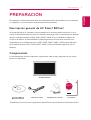 15
15
-
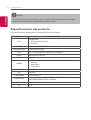 16
16
-
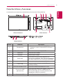 17
17
-
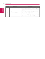 18
18
-
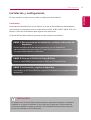 19
19
-
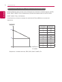 20
20
-
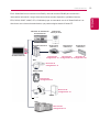 21
21
-
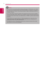 22
22
-
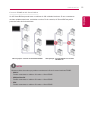 23
23
-
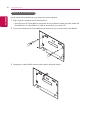 24
24
-
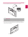 25
25
-
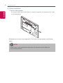 26
26
-
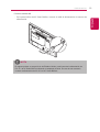 27
27
-
 28
28
-
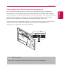 29
29
-
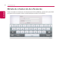 30
30
-
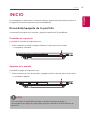 31
31
-
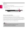 32
32
-
 33
33
-
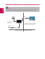 34
34
-
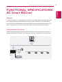 35
35
-
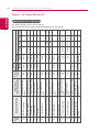 36
36
-
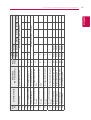 37
37
-
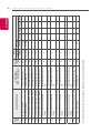 38
38
-
 39
39
-
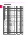 40
40
-
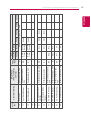 41
41
-
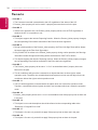 42
42
-
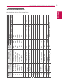 43
43
-
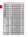 44
44
-
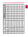 45
45
-
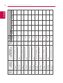 46
46
-
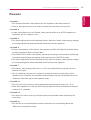 47
47
-
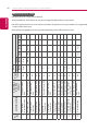 48
48
-
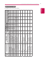 49
49
-
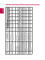 50
50
-
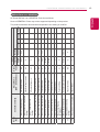 51
51
-
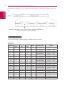 52
52
-
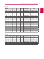 53
53
-
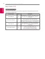 54
54
-
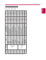 55
55
-
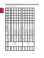 56
56
-
 57
57
-
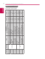 58
58
-
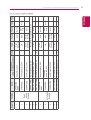 59
59
-
 60
60
-
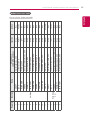 61
61
-
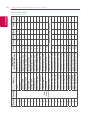 62
62
-
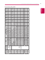 63
63
-
 64
64
-
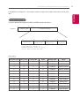 65
65
-
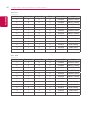 66
66
-
 67
67
-
 68
68
-
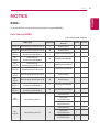 69
69
-
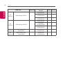 70
70
-
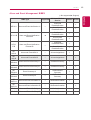 71
71
-
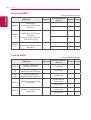 72
72
-
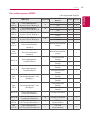 73
73
-
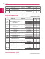 74
74
-
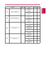 75
75
-
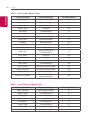 76
76
-
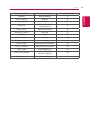 77
77
-
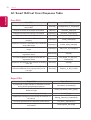 78
78
-
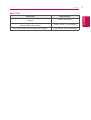 79
79
-
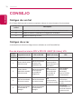 80
80
-
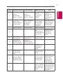 81
81
-
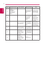 82
82
-
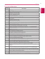 83
83
-
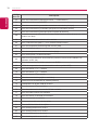 84
84
-
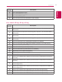 85
85
-
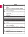 86
86
-
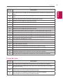 87
87
-
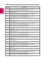 88
88
-
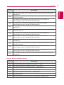 89
89
-
 90
90
-
 91
91
-
 92
92


LG AC Smart BACnet Guía de instalación
- Tipo
- Guía de instalación
- Este manual también es adecuado para
en otros idiomas
Artículos relacionados
-
LG PACS4B000 Guía de instalación
-
LG PACS5A000 Guía de instalación
-
-
LG PQCSW421E0A Manual de usuario
-
LG PQNFB17C0.ENCXLEU Guía de instalación
-
LG PLNWKB000.ENCXLEU Manual de usuario
-
-
LG PQCSW320A1E Manual de usuario
-
-