Graff G-2311-LM40-SN Guía de instalación
- Categoría
- Artículos sanitarios
- Tipo
- Guía de instalación

IOG 2268.50
Rev. 1 March 2010
5
IOG 2268.50
Rev. 1 March 2010
4
IOG 2268.50
Rev. 1 March 2010
3
IOG 2268.50
Rev. 1 March 2010
2
IOG 2268.50
1
Dear Customer Estimado Cliente
Thank you for selecting our product. We are confident we can fully satisfy Muchas gracias por elegir nuestro producto. Estamos seguros que podemos
your expectations by offering you a wide range of technologically advanced satisfacer completamente sus expectativas ofreciéndole una amplia variedad
products which directly result from our many years of experience in faucet
de productos tecnológicamente avanzados que resultan directamente de
and fitting production.
muchos años de experiencia en grifos y su producción apropiada.
ENGLISH
~
ESPANOL
This faucet complies with NSF61/9, ASME/ANSI A112.18.1
and CSA B 125 Standards.
Este grifo se encuentra conforme con losestandares de NSF61/9,
de ASME/ANSI A112.18.1 y de CSA B 125.
Installation Instructions Instrucciones de Instalación
TWO HANDLE WIDESPREAD LAVATORY FAUCET
GRIFO DE DOS MANILLAS DE EXTENSIÓN
For care, use soft towel with soap and water only! Under no
circumstances should you use any chemicals. For faucets
with ORB (oil rubbed bronze) finish please be extra careful
not to damage, scuff or ruin the finish during the installation
and cleaning!
ATTENTION!
ATENCIÓN!
Para el cuidado, utilice solamente una toalla suave con jabón y aqua!
Bajo ninguna circunstancia no use productos químicos. Con los grifos
de acabado ORB (bronce frotado con aceite) hay que tener un cuidado
especial para no dańar, arańar o destruir el acabado durante su
instalación o limpieza!
ENGLISH
~
ESPANOL
1
2
3
4
5
6
7
8
9
10
11
12
13
14
15R
15L
16
17
18
19
20
21
22
22.1
22.2
23
24
25
K1
K2
K3
K4
1
2
3
4
5
6
7
8
9
10
11
12
13
14
15R
15L
16
17
18
19
20
21
22
22.1
22.2
23
24
25
K1
K2
K3
K4
SPOUT
AERATOR
SET SCREW
SPOUT BASE
THREADED STUB PIPE
DRAIN LIFT-ROD
ORIFICE MR05 /FLOW RESTRICTOR/
RUBBER WASHER
METAL WASHER
MOUNTING NUT
O-RING SEAL
NOZZLE
T-CONNECTION
HOSE, 11-13/16” (300mm) LENGTH (2 PCS.)
VALVE WITH A 1/4 TURN CERAMIC HEAD
/clockwise opening/
VALVE WITH A 1/4 TURN CERAMIC HEAD
/counterclockwise opening/
HEAD SPINDLE ELONGATION (2 PCS.)
SCREW (2 PCS.)
NUT (2 PCS.)
METAL WASHER (2 PCS.)
RUBBER WASHER (2 PCS.)
VALVE FLANGE (2 PCS.)
LEVER ASSEMBLY (2 PCS.)
LEVER (2 PCS.)
HANDLE BASE (2 PCS.)
CONE GASKET (2 PCS.)
METAL WASHER (2 PCS.)
COUPLING NUT (2 PCS.)
5/64” (2mm) HEX KEY
1/16” (1.5mm) HEX KEY
SPECIAL KEY FOR THE AERATOR
SOCKET WRENCH (S17X115mm - for ceramic heads)
CAÑO
AEREADOR
TORNILLO DE APRIETE
BASE DEL CAÑO
TUBO ROSCADO
VARILLA ELEVADORA DE DESAGÜE
ORIFICIO MR05
ARANDELA DE CAUCHO
ARANDELA DE METAL
TUERCA DE MONTAJE
JUNTA TÓRICA
TOBERA
TUBO EN “T”
MANGUERA LONGITUD DE 11-13/16” (300mm) (2 PIEZAS)
VÁLVULA CON LA CABEZA CERÁMICA 1/4 GIRO /abre hacia la
derecha/
VÁLVULA CON LA CABEZA CERÁMICA 1/4 GIRO
/abre hacia la izquierda/
EXTENSIÓN DEL HUSO DE LA CABEZA (2 PIEZAS)
TORNILLO (2 PIEZAS)
TUERCA (2 PIEZAS)
ARANDELA DE METAL (2 PIEZAS)
ARANDELA DE GOMA (2 PIEZAS)
BRIDA DE LA VÁLVULA (2 PIEZAS)
JUEGO DE LA PALANCA (2 PIEZAS)
PALANCA (2 PIEZAS)
BASE DE LA PALANCA (2 PIEZAS)
JUNTA DE CONO (2 PIEZAS)
ARANDELA DE METAL (2 PIEZAS)
TUERCA ACOPLAMIENTO (2 PIEZAS)
LLAVE ALLÉN 5/64” (2mm)
LLAVE ALLÉN 1/16” (1.5mm)
LLAVE ESPECIAL PARA EL AEREADOR
LLAVE INGLESA (S17x115mm - para cabezas)
1
2.1
2.5
2.2
2.6
2.3
2.7
2.4
2.8
3
~
ESPANOL
~
ESPANOL
~
ESPANOL
See figs. 2.1-2.8
1. Check the label on the valve in order to identify hot water valve (red
label) and cold water valve (blue label). Install the hot water valve on
the left side of the spout, and the cold water valve on its right side.
2. Screw the nut (18) on the valve (15L) and put metal gasket (19) and
rubber gasket (20) - fig. 2.1. Insert the valve (15L) through the
installation opening from under the sink. From above, screw the valve
flange (21) home, at the same time holding the valve (15L) - fig. 2.2.
After proper positioning of the valve under the sink, screw the nut (18).
3. Make sure the valve is in “closed” position by turning the valve spindle
to the right (hot water valve (15L) marked with red label) until you
feel strong resistance. For the cold water valve (15R), marked with
blue label, turn the valve spindle to the left.
4. Place the lever assembly (22) on the valve spindle extension (16).
Place the handle base (22.2) in the correct position against the valve
flange (21) - fig. 2.3.
5. Check, if you are able to obtain the required lever position, according
to fig. 2.7. If you cannot position the lever (22.1) correctly in relation
1. The levers open water discharge and regulate water flow. The
discharge is fully open when the lever is turned 90° (clockwise – cold
water lever on the right side, and counterclockwise – hot water lever
on the left side). The rate of water flow is regulated between positions
0° - 90°.
2. By pressing the drain plug (item 2, fig. 4) you will stop water from
running out of the lavatory, by pressing it again, you open the drain
plug to restore drainage flow.
3. It is recommended that every 3-6 months (depending on water
quality) you remove the aerator (item 2, fig. 1) from the faucet spout in
order to remove any impurities. For this purpose, release the screw
(3) using the hex key (K2), next pull out the aerator (2) using special
key (K3) supplied.
See fig. 3
1. Pass the spout (1) and the threaded pipe (5) through the middle
mounting hole in the mounting surface.
2. Place the rubber washer (8), metal washer (9) and screw the nut (10)
on the threaded pipe (5) from under the sink.
3. Make sure the spout is positioned correctly on the mounting surface.
Tighten up the nut (10) using an adjustable spanner.
4. Insert the nozzle (12) and the o-ring washer (11) into the
T-connection (13). Make sure that the orifice (7) is inside threaded
pipe (5).
5. Screw the T-connection (13) onto the threaded pipe (5) of the spout
according to fig. 3.
6. Insert the pull-rod bar (6) into the hole in the spout base (4) from
above.
to the sink edge (you notice distinct shift of Δ angle to the required
positioning - as shown on fig. 2.4). Take the lever assembly (22) off
the valve spindle extension (16) – see fig. 2.5. Loose the bolt (17)
and move the valve spindle extension (16) one tooth on valve head
splines and screw the bolt (17) back into position - fig. 2.6. Place the
lever assembly (22) on the valve spindle extension (16) and check
the correct positioning of the lever (22.1) - fig. 2.7.
If the position of the lever (22.1) is proper, you may tighten the set
screw (23) using hex key (K1) according to the drawing 2.8.
However, if the position of the lever (22.1) is still incorrect, move the
valve spindle extension (16) one more tooth on valve head splines and
check the lever (22.1) positioning once again.
6. After installation of the hot water valve (15L) and the lever assembly
(22), repeat the above mentioned steps for installing the cold water
valve (15R).
See figs. 2.1-2.8
1. Check the label on the valve in order to identify hot water valve (red
label) and cold water valve (blue label). Install the hot water valve on
the left side of the spout, and the cold water valve on its right side.
2. Screw the nut (18) on the valve (15L) and put metal gasket (19) and
rubber gasket (20) - fig. 2.1. Insert the valve (15L) through the
installation opening from under the sink. From above, screw the valve
flange (21) home, at the same time holding the valve (15L) - fig. 2.2.
After proper positioning of the valve under the sink, screw the nut (18).
3. Make sure the valve is in “closed” position by turning the valve spindle
to the right (hot water valve (15L) marked with red label) until you
feel strong resistance. For the cold water valve (15R), marked with
blue label, turn the valve spindle to the left.
4. Place the lever assembly (22) on the valve spindle extension (16).
Place the handle base (22.2) in the correct position against the valve
flange (21) - fig. 2.3.
5. Check, if you are able to obtain the required lever position, according
to fig. 2.7. If you cannot position the lever (22.1) correctly in relation
1. Para dejar salir el agua y ajustar el flujo de la misma sirven las palancas.
La apertura total ocurre al girar la palanca por el ángulo de 90° (sentido
reloj – la palanca del agua fría colocada por el lado derecho, sentido
contra reloj – la palanca del agua caliente colocada por el lado
izquierdo). El ajuste del flujo del agua se hace en el rango de 0° - 90°.
2. Apretar el tapón de escape (pos. 2, dis. 4) hace el cierre de espace del
agua del lavabo, volver a apretar el tapón abre el flujo.
3. Una vez a 3-6 meses (dependiendo de la calidad del agua) se
recomienda quitar el aereador (pos. 2, la fig. 1) del caño de la
mezcladora con el fin de limpiarlo de todo tipo de ensuciamiento. Para
eso desbloquear el tornillo (3) usando la llave hexagonal (K2)
después sacar el aereador (2) usando una llave especial (K3) anexa al
juego.
Ver. fig. 3
1. El caño (1) con tubo roscado (5) meter en el orificio central de la
superficie de montaje.
2. Por debajo del lavabo, en el tubo roscado (5) meter la arandela de
caucho (8), la arandela de metal (9), luego atornillar la tuerca (10).
3. Asegurarse de que el caño se encuentra en la posición adecuada en la
superficie de montaje. Atornillar la tuerca (10) con el uso de la llave
inglesa.
4. Introducir la tobera (12) y la junta tórica (11) en el tubo en T (13).
Asegúrase que el orificio (7) es dentro el tubo roscado (5).
5. Atornillar el tubo en T (13) en el tubo roscado (5) del caño según la
fig. 2.
6. Por encima, en el orificio de la base del caño (4) introducir la varilla
elevadora de desagüe (6).
to the sink edge (you notice distinct shift of Δ angle to the required
positioning - as shown on fig. 2.4). Take the lever assembly (22) off
the valve spindle extension (16) – see fig. 2.5. Loose the bolt (17) and
move the valve spindle extension (16) one tooth on valve head splines
and screw the bolt (17) back into position - fig. 2.6. Place the lever
assembly (22) on the valve spindle extension (16) and check the
correct positioning of the lever (22.1) - fig. 2.7.
If the position of the lever (22.1) is proper, you may tighten the set
screw (23) using hex key (K1) according to the drawing 2.8.
However, if the position of the lever (22.1) is still incorrect, move the
valve spindle extension (16) one more tooth on valve head splines and
check the lever (22.1) positioning once again.
6. After installation of the hot water valve (15L) and the lever assembly
(22), repeat the above mentioned steps for installing the cold water
valve (15R).
ENGLISH
ENGLISH
ENGLISH
ENGLISH
~
ESPANOL
4
CARE AND MAINTENANCE CUIDADO Y MANTENIMIENTO
ENGLISH
~
ESPANOL
WARRANTY GARANTÍA
All dimensions and drawings are for reference only. For details, please refer to actual products.
Todas las dimensiones y dibujos sirven únicamente de referencia. Para consultar detalles, ver los productos.
Your Graff faucet is designed and engineered in accordance with the
highest quality and performance standards. Be sure not to damage the
finish during installation. Care should be given to the cleaning of this
product. Although its finish is extremely durable, it can be damaged by
harsh abrasives or polish. Never use abrasive cleaners, acids,
solvents, etc. to clean any Graff product. To clean, simply wipe
gently with a damp cloth and blot dry with a soft towel.
Warranty conditions and warranty registration card are outlined on a
separate sheet.
Su grifo de la Graff esta diseńado y dirigido acuerdo con los estándares de
funcionamiento y calidad más altos. Este seguro no dańar las terminaciones
del grifo durante la instalación. Cuide el producto manteniendolo siempre
limpio. Aunque su acabado es extremadamente durable, puede ser dańado
por los abrasivos o pulientes ásperos. Nunca utilice limpiadores
abrasivos, ácidos, solventes, el etc. para limpiar cualquier producto
de la Graff. Para limpiar, simplemente use un pańo húmedo y seque
con una toalla suave.
Las condiciones de la garantía y la tarjeta del registro de la garantía se
encuentran en una pagina separada.
2-3/8" (60mm)
2-3/8" (60mm)
1-13/16"
(46mm)
7/16" x 1-9/16"
(11 x 40mm)
1/4" (6.5mm)
2-1/2" (63mm)
2-7/8" (73mm)
1-13/16"
(46mm)
13/16"
(21mm)
~ 5-1/2" (~ 177mm)
~5-1/2" (~ 139mm)
6-1/2" (164,5mm)
Model
Modelo
IMMERSION 2311-LM40
23 23
22.2
22.1
21
20
19
1
4
5
9
10
11
12
8
7
6
3
2
18
17
16
24
14 13
25
26
15L
22.2
22.1
21
20
19
18
17
16
24
14
25
26
15R
22
22
K1
K2
K4
K3
~
ESPANOL
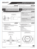
For easy installation of your
GRAFF faucet you will need:
to READ ALL the instructions
completely before beginning,
to READ ALL the warnings, care and
maintenance information.
To complete the project, you
should:
gather the tools and all the parts
you will need,
prepare the mounting area,
mount the faucet,
connect the supply lines,
finally test and flush the faucet.
You should have the following
tools:
adjustable wrench,
adjustable pliers,
hex key (included in the box),
®
Teflon tape.
Para la instalación fácil de su grifo
de la GRAFF usted necesitará:
LEER TODAS las instrucciones
completamente antes de comenzar,
LEER TODA la información sobre las
advertencias, cuidado y
mantenimiento.
Para terminar el proyecto, usted
debe:
recolectar las herramientas y todas
las piezas que usted necesitará,
prepare el área para el montaje,
monte el grifo,
conecte las líneas de fuente,
finalmente pruebe y limpie el grifo
con un chorro de agua.
Usted debe tener las herramientas
siguientes:
llave ajustable,
alicates acanalados,
llave hexagonal (incluido en la caja),
®
cinta adhesiva de Teflon .
ENGLISH
Ø1-3/16"
( 30mm)Ø
Ø1-3/16"
( 30mm)Ø
Ø1-3/16"
( 30mm)Ø
1/4"
(6mm)
SIZE AND SPACING OF ASSEMBLY OPENINGS
TAMAÑOS Y DISTRIBUCIÓN DE LOS ORIFICIOS DE MONTAJE
20
19
18
15L15L
16
21
22
22.1
22.2
23
16
22
16
17
21
16
22
22.1
22.2
K1
23
22.1
22.2
21
15L
20
18
19
MAX. 2"
(MAX. 50mm)
MAX. 2"
(MAX. 50mm)
Hot water valve is marked
with red sticker
La válvula de agua caliente
está marcada con
le etiqueta roja
Cold water valve is
marked with blue sticker
La válvula de agua fría
está marcada con
le etiqueta azul
Supply tube - 3/8" O.D. (9.5mm)
Entrada de agua caliente
tuberia - 3/8" O.D. (9.5mm)
Supply tube - 3/8" O.D. (9.5mm)
Entrada de agua fría
tuberia - 3/8" O.D. (9.5mm)
1
INSTALLATION OF VALVES AND LEVERS MONTAJE DE VÁLVULAS Y PALANCAS
3
OPERATING INSTRUCTION LA DESCRIPCIÓN DEL FUNCIONAMIENTO
2
INSTALLATION OF THE SPOUT MONTAJE DE VÁLVULAS Y PALANCAS
SET-UP DIAGRAM DIAGRAMA DE INSTALACIÓN
22.1
Δ
Δ
1
5
7
10
11
12
13
4
6
8
9
5
MAX. 2"
(MAX. 50mm)
~ 8"-12"
(~ 204mm) - (~ 305mm)
~ 8"-12"
(~ 204mm) - (~ 305mm)
Rev. 3 April 2014

IOG 2268.50
Rev. 1 March 2010
5
IOG 2268.50
Rev. 1 March 2010
4
IOG 2268.50
Rev. 1 March 2010
3
IOG 2268.50
2
IOG 2268.50
Rev. 1 March 2010
1
Dear Customer Estimado Cliente
Thank you for selecting our product. We are confident we can fully satisfy Muchas gracias por elegir nuestro producto. Estamos seguros que podemos
your expectations by offering you a wide range of technologically advanced satisfacer completamente sus expectativas ofreciéndole una amplia variedad
products which directly result from our many years of experience in faucet
de productos tecnológicamente avanzados que resultan directamente de
and fitting production.
muchos años de experiencia en grifos y su producción apropiada.
ENGLISH
~
ESPANOL
This faucet complies with NSF61/9, ASME/ANSI A112.18.1
and CSA B 125 Standards.
Este grifo se encuentra conforme con losestandares de NSF61/9,
de ASME/ANSI A112.18.1 y de CSA B 125.
Installation Instructions Instrucciones de Instalación
TWO HANDLE WIDESPREAD LAVATORY FAUCET
GRIFO DE DOS MANILLAS DE EXTENSIÓN
This faucet complies with NSF61/9, ASME/ANSI A112.18.1
and CSA B 125 Standards.
Este grifo se encuentra conforme con losestandares de NSF61/9,
de ASME/ANSI A112.18.1 y de CSA B 125.
Installation Instructions Instrucciones de Instalación
TWO HANDLE WIDESPREAD LAVATORY FAUCET
GRIFO DE DOS MANILLAS DE EXTENSIÓN
This faucet complies with NSF61/9, ASME/ANSI A112.18.1
and CSA B 125 Standards.
Este grifo se encuentra conforme con losestandares de NSF61/9,
de ASME/ANSI A112.18.1 y de CSA B 125.
Installation Instructions Instrucciones de Instalación
TWO HANDLE WIDESPREAD LAVATORY FAUCET
GRIFO DE DOS MANILLAS DE EXTENSIÓN
This faucet complies with NSF61/9, ASME/ANSI A112.18.1
and CSA B 125 Standards.
Este grifo se encuentra conforme con losestandares de NSF61/9,
de ASME/ANSI A112.18.1 y de CSA B 125.
Installation Instructions Instrucciones de Instalación
TWO HANDLE WIDESPREAD LAVATORY FAUCET
GRIFO DE DOS MANILLAS DE EXTENSIÓN
This faucet complies with NSF61/9, ASME/ANSI A112.18.1
and CSA B 125 Standards.
Este grifo se encuentra conforme con losestandares de NSF61/9,
de ASME/ANSI A112.18.1 y de CSA B 125.
Installation Instructions Instrucciones de Instalación
TWO HANDLE WIDESPREAD LAVATORY FAUCET
GRIFO DE DOS MANILLAS DE EXTENSIÓN
For care, use soft towel with soap and water only! Under no
circumstances should you use any chemicals. For faucets
with ORB (oil rubbed bronze) finish please be extra careful
not to damage, scuff or ruin the finish during the installation
and cleaning!
ATTENTION!
ATENCIÓN!
Para el cuidado, utilice solamente una toalla suave con jabón y aqua!
Bajo ninguna circunstancia no use productos químicos. Con los grifos
de acabado ORB (bronce frotado con aceite) hay que tener un cuidado
especial para no dańar, arańar o destruir el acabado durante su
instalación o limpieza!
ENGLISH
~
ESPANOL
1
2
3
4
5
6
7
8
9
10
11
12
13
14
15R
15L
16
17
18
19
20
21
22
22.1
22.2
23
24
25
K1
K2
K3
K4
1
2
3
4
5
6
7
8
9
10
11
12
13
14
15R
15L
16
17
18
19
20
21
22
22.1
22.2
23
24
25
K1
K2
K3
K4
SPOUT
AERATOR
SET SCREW
SPOUT BASE
THREADED STUB PIPE
DRAIN LIFT-ROD
ORIFICE MR05 /FLOW RESTRICTOR/
RUBBER WASHER
METAL WASHER
MOUNTING NUT
O-RING SEAL
NOZZLE
T-CONNECTION
HOSE, 11-13/16” (300mm) LENGTH (2 PCS.)
VALVE WITH A 1/4 TURN CERAMIC HEAD
/clockwise opening/
VALVE WITH A 1/4 TURN CERAMIC HEAD
/counterclockwise opening/
HEAD SPINDLE ELONGATION (2 PCS.)
SCREW (2 PCS.)
NUT (2 PCS.)
METAL WASHER (2 PCS.)
RUBBER WASHER (2 PCS.)
VALVE FLANGE (2 PCS.)
LEVER ASSEMBLY (2 PCS.)
LEVER (2 PCS.)
HANDLE BASE (2 PCS.)
CONE GASKET (2 PCS.)
METAL WASHER (2 PCS.)
COUPLING NUT (2 PCS.)
5/64” (2mm) HEX KEY
1/16” (1.5mm) HEX KEY
SPECIAL KEY FOR THE AERATOR
SOCKET WRENCH (S17X115mm - for ceramic heads)
CAÑO
AEREADOR
TORNILLO DE APRIETE
BASE DEL CAÑO
TUBO ROSCADO
VARILLA ELEVADORA DE DESAGÜE
ORIFICIO MR05
ARANDELA DE CAUCHO
ARANDELA DE METAL
TUERCA DE MONTAJE
JUNTA TÓRICA
TOBERA
TUBO EN “T”
MANGUERA LONGITUD DE 11-13/16” (300mm) (2 PIEZAS)
VÁLVULA CON LA CABEZA CERÁMICA 1/4 GIRO /abre hacia la
derecha/
VÁLVULA CON LA CABEZA CERÁMICA 1/4 GIRO
/abre hacia la izquierda/
EXTENSIÓN DEL HUSO DE LA CABEZA (2 PIEZAS)
TORNILLO (2 PIEZAS)
TUERCA (2 PIEZAS)
ARANDELA DE METAL (2 PIEZAS)
ARANDELA DE GOMA (2 PIEZAS)
BRIDA DE LA VÁLVULA (2 PIEZAS)
JUEGO DE LA PALANCA (2 PIEZAS)
PALANCA (2 PIEZAS)
BASE DE LA PALANCA (2 PIEZAS)
JUNTA DE CONO (2 PIEZAS)
ARANDELA DE METAL (2 PIEZAS)
TUERCA ACOPLAMIENTO (2 PIEZAS)
LLAVE ALLÉN 5/64” (2mm)
LLAVE ALLÉN 1/16” (1.5mm)
LLAVE ESPECIAL PARA EL AEREADOR
LLAVE INGLESA (S17x115mm - para cabezas)
1
2.1
2.5
2.2
2.6
2.3
2.7
2.4
2.8
3
~
ESPANOL
~
ESPANOL
~
ESPANOL
See figs. 2.1-2.8
1. Check the label on the valve in order to identify hot water valve (red
label) and cold water valve (blue label). Install the hot water valve on
the left side of the spout, and the cold water valve on its right side.
2. Screw the nut (18) on the valve (15L) and put metal gasket (19) and
rubber gasket (20) - fig. 2.1. Insert the valve (15L) through the
installation opening from under the sink. From above, screw the valve
flange (21) home, at the same time holding the valve (15L) - fig. 2.2.
After proper positioning of the valve under the sink, screw the nut (18).
3. Make sure the valve is in “closed” position by turning the valve spindle
to the right (hot water valve (15L) marked with red label) until you
feel strong resistance. For the cold water valve (15R), marked with
blue label, turn the valve spindle to the left.
4. Place the lever assembly (22) on the valve spindle extension (16).
Place the handle base (22.2) in the correct position against the valve
flange (21) - fig. 2.3.
5. Check, if you are able to obtain the required lever position, according
to fig. 2.7. If you cannot position the lever (22.1) correctly in relation
1. The levers open water discharge and regulate water flow. The
discharge is fully open when the lever is turned 90° (clockwise – cold
water lever on the right side, and counterclockwise – hot water lever
on the left side). The rate of water flow is regulated between positions
0° - 90°.
2. By pressing the drain plug (item 2, fig. 4) you will stop water from
running out of the lavatory, by pressing it again, you open the drain
plug to restore drainage flow.
3. It is recommended that every 3-6 months (depending on water
quality) you remove the aerator (item 2, fig. 1) from the faucet spout in
order to remove any impurities. For this purpose, release the screw
(3) using the hex key (K2), next pull out the aerator (2) using special
key (K3) supplied.
See fig. 3
1. Pass the spout (1) and the threaded pipe (5) through the middle
mounting hole in the mounting surface.
2. Place the rubber washer (8), metal washer (9) and screw the nut (10)
on the threaded pipe (5) from under the sink.
3. Make sure the spout is positioned correctly on the mounting surface.
Tighten up the nut (10) using an adjustable spanner.
4. Insert the nozzle (12) and the o-ring washer (11) into the
T-connection (13). Make sure that the orifice (7) is inside threaded
pipe (5).
5. Screw the T-connection (13) onto the threaded pipe (5) of the spout
according to fig. 3.
6. Insert the pull-rod bar (6) into the hole in the spout base (4) from
above.
to the sink edge (you notice distinct shift of Δ angle to the required
positioning - as shown on fig. 2.4). Take the lever assembly (22) off
the valve spindle extension (16) – see fig. 2.5. Loose the bolt (17)
and move the valve spindle extension (16) one tooth on valve head
splines and screw the bolt (17) back into position - fig. 2.6. Place the
lever assembly (22) on the valve spindle extension (16) and check
the correct positioning of the lever (22.1) - fig. 2.7.
If the position of the lever (22.1) is proper, you may tighten the set
screw (23) using hex key (K1) according to the drawing 2.8.
However, if the position of the lever (22.1) is still incorrect, move the
valve spindle extension (16) one more tooth on valve head splines and
check the lever (22.1) positioning once again.
6. After installation of the hot water valve (15L) and the lever assembly
(22), repeat the above mentioned steps for installing the cold water
valve (15R).
See figs. 2.1-2.8
1. Check the label on the valve in order to identify hot water valve (red
label) and cold water valve (blue label). Install the hot water valve on
the left side of the spout, and the cold water valve on its right side.
2. Screw the nut (18) on the valve (15L) and put metal gasket (19) and
rubber gasket (20) - fig. 2.1. Insert the valve (15L) through the
installation opening from under the sink. From above, screw the valve
flange (21) home, at the same time holding the valve (15L) - fig. 2.2.
After proper positioning of the valve under the sink, screw the nut (18).
3. Make sure the valve is in “closed” position by turning the valve spindle
to the right (hot water valve (15L) marked with red label) until you
feel strong resistance. For the cold water valve (15R), marked with
blue label, turn the valve spindle to the left.
4. Place the lever assembly (22) on the valve spindle extension (16).
Place the handle base (22.2) in the correct position against the valve
flange (21) - fig. 2.3.
5. Check, if you are able to obtain the required lever position, according
to fig. 2.7. If you cannot position the lever (22.1) correctly in relation
1. Para dejar salir el agua y ajustar el flujo de la misma sirven las palancas.
La apertura total ocurre al girar la palanca por el ángulo de 90° (sentido
reloj – la palanca del agua fría colocada por el lado derecho, sentido
contra reloj – la palanca del agua caliente colocada por el lado
izquierdo). El ajuste del flujo del agua se hace en el rango de 0° - 90°.
2. Apretar el tapón de escape (pos. 2, dis. 4) hace el cierre de espace del
agua del lavabo, volver a apretar el tapón abre el flujo.
3. Una vez a 3-6 meses (dependiendo de la calidad del agua) se
recomienda quitar el aereador (pos. 2, la fig. 1) del caño de la
mezcladora con el fin de limpiarlo de todo tipo de ensuciamiento. Para
eso desbloquear el tornillo (3) usando la llave hexagonal (K2)
después sacar el aereador (2) usando una llave especial (K3) anexa al
juego.
Ver. fig. 3
1. El caño (1) con tubo roscado (5) meter en el orificio central de la
superficie de montaje.
2. Por debajo del lavabo, en el tubo roscado (5) meter la arandela de
caucho (8), la arandela de metal (9), luego atornillar la tuerca (10).
3. Asegurarse de que el caño se encuentra en la posición adecuada en la
superficie de montaje. Atornillar la tuerca (10) con el uso de la llave
inglesa.
4. Introducir la tobera (12) y la junta tórica (11) en el tubo en T (13).
Asegúrase que el orificio (7) es dentro el tubo roscado (5).
5. Atornillar el tubo en T (13) en el tubo roscado (5) del caño según la
fig. 2.
6. Por encima, en el orificio de la base del caño (4) introducir la varilla
elevadora de desagüe (6).
to the sink edge (you notice distinct shift of Δ angle to the required
positioning - as shown on fig. 2.4). Take the lever assembly (22) off
the valve spindle extension (16) – see fig. 2.5. Loose the bolt (17) and
move the valve spindle extension (16) one tooth on valve head splines
and screw the bolt (17) back into position - fig. 2.6. Place the lever
assembly (22) on the valve spindle extension (16) and check the
correct positioning of the lever (22.1) - fig. 2.7.
If the position of the lever (22.1) is proper, you may tighten the set
screw (23) using hex key (K1) according to the drawing 2.8.
However, if the position of the lever (22.1) is still incorrect, move the
valve spindle extension (16) one more tooth on valve head splines and
check the lever (22.1) positioning once again.
6. After installation of the hot water valve (15L) and the lever assembly
(22), repeat the above mentioned steps for installing the cold water
valve (15R).
ENGLISH
ENGLISH
ENGLISH
ENGLISH
~
ESPANOL
4
CARE AND MAINTENANCE CUIDADO Y MANTENIMIENTO
ENGLISH
~
ESPANOL
WARRANTY GARANTÍA
All dimensions and drawings are for reference only. For details, please refer to actual products.
Todas las dimensiones y dibujos sirven únicamente de referencia. Para consultar detalles, ver los productos.
Your Graff faucet is designed and engineered in accordance with the
highest quality and performance standards. Be sure not to damage the
finish during installation. Care should be given to the cleaning of this
product. Although its finish is extremely durable, it can be damaged by
harsh abrasives or polish. Never use abrasive cleaners, acids,
solvents, etc. to clean any Graff product. To clean, simply wipe
gently with a damp cloth and blot dry with a soft towel.
Warranty conditions and warranty registration card are outlined on a
separate sheet.
Su grifo de la Graff esta diseńado y dirigido acuerdo con los estándares de
funcionamiento y calidad más altos. Este seguro no dańar las terminaciones
del grifo durante la instalación. Cuide el producto manteniendolo siempre
limpio. Aunque su acabado es extremadamente durable, puede ser dańado
por los abrasivos o pulientes ásperos. Nunca utilice limpiadores
abrasivos, ácidos, solventes, el etc. para limpiar cualquier producto
de la Graff. Para limpiar, simplemente use un pańo húmedo y seque
con una toalla suave.
Las condiciones de la garantía y la tarjeta del registro de la garantía se
encuentran en una pagina separada.
2-3/8" (60mm)
2-3/8" (60mm)
1-13/16"
(46mm)
7/16" x 1-9/16"
(11 x 40mm)
1/4" (6.5mm)
2-1/2" (63mm)
2-7/8" (73mm)
1-13/16"
(46mm)
13/16"
(21mm)
~ 5-9/16" (~ 142mm)
~ 4-5/16" (~ 109mm)
6-3/8" (162mm)
Model
Modelo
IMMERSION 2311-LM40
23 23
22.2
22.1
21
20
19
1
4
5
9
10
11
12
8
7
6
3
2
18
17
16
24
14 13
25
26
15L
22.2
22.1
21
20
19
18
17
16
24
14
25
26
15R
22
22
K1
K2
K4
K3
~
ESPANOL
For easy installation of your
GRAFF faucet you will need:
to READ ALL the instructions
completely before beginning,
to READ ALL the warnings, care and
maintenance information.
To complete the project, you
should:
gather the tools and all the parts
you will need,
prepare the mounting area,
mount the faucet,
connect the supply lines,
finally test and flush the faucet.
You should have the following
tools:
adjustable wrench,
adjustable pliers,
hex key (included in the box),
®
Teflon tape.
Para la instalación fácil de su grifo
de la GRAFF usted necesitará:
LEER TODAS las instrucciones
completamente antes de comenzar,
LEER TODA la información sobre las
advertencias, cuidado y
mantenimiento.
Para terminar el proyecto, usted
debe:
recolectar las herramientas y todas
las piezas que usted necesitará,
prepare el área para el montaje,
monte el grifo,
conecte las líneas de fuente,
finalmente pruebe y limpie el grifo
con un chorro de agua.
Usted debe tener las herramientas
siguientes:
llave ajustable,
alicates acanalados,
llave hexagonal (incluido en la caja),
®
cinta adhesiva de Teflon .
ENGLISH
Ø1-3/16"
( 30mm)Ø
Ø1-3/16"
( 30mm)Ø
Ø1-3/16"
( 30mm)Ø
~ 8" (~ 204mm)
1/4"
(6mm)
SIZE AND SPACING OF ASSEMBLY OPENINGS
TAMAÑOS Y DISTRIBUCIÓN DE LOS ORIFICIOS DE MONTAJE
20
19
18
15L15L
16
21
22
22.1
22.2
23
16
22
16
17
21
16
22
22.1
22.2
K1
23
22.1
22.2
21
15L
20
18
19
MAX. 2"
(MAX. 50mm)
~ 8" (~ 204mm)
MAX. 2"
(MAX. 50mm)
Hot water valve is marked
with red sticker
La válvula de agua caliente
está marcada con
le etiqueta roja
Cold water valve is
marked with blue sticker
La válvula de agua fría
está marcada con
le etiqueta azul
Supply tube - 3/8" O.D. (9.5mm)
Entrada de agua caliente
tuberia - 3/8" O.D. (9.5mm)
Supply tube - 3/8" O.D. (9.5mm)
Entrada de agua fría
tuberia - 3/8" O.D. (9.5mm)
1
INSTALLATION OF VALVES AND LEVERS MONTAJE DE VÁLVULAS Y PALANCAS
3
OPERATING INSTRUCTION LA DESCRIPCIÓN DEL FUNCIONAMIENTO
2
INSTALLATION OF THE SPOUT MONTAJE DE VÁLVULAS Y PALANCAS
SET-UP DIAGRAM DIAGRAMA DE INSTALACIÓN
22.1
Δ
Δ
1
5
7
10
11
12
13
4
6
8
9
5
MAX. 2"
(MAX. 50mm)
Rev. 3 April 2014

IOG 2268.50
Rev. 1 March 2010
5
IOG 2268.50
Rev. 1 March 2010
4
IOG 2268.50
3
IOG 2268.50
Rev. 1 March 2010
2
IOG 2268.50
Rev. 1 March 2010
1
Dear Customer Estimado Cliente
Thank you for selecting our product. We are confident we can fully satisfy Muchas gracias por elegir nuestro producto. Estamos seguros que podemos
your expectations by offering you a wide range of technologically advanced satisfacer completamente sus expectativas ofreciéndole una amplia variedad
products which directly result from our many years of experience in faucet
de productos tecnológicamente avanzados que resultan directamente de
and fitting production.
muchos años de experiencia en grifos y su producción apropiada.
ENGLISH
~
ESPANOL
This faucet complies with NSF61/9, ASME/ANSI A112.18.1
and CSA B 125 Standards.
Este grifo se encuentra conforme con losestandares de NSF61/9,
de ASME/ANSI A112.18.1 y de CSA B 125.
Installation Instructions Instrucciones de Instalación
TWO HANDLE WIDESPREAD LAVATORY FAUCET
GRIFO DE DOS MANILLAS DE EXTENSIÓN
This faucet complies with NSF61/9, ASME/ANSI A112.18.1
and CSA B 125 Standards.
Este grifo se encuentra conforme con losestandares de NSF61/9,
de ASME/ANSI A112.18.1 y de CSA B 125.
Installation Instructions Instrucciones de Instalación
TWO HANDLE WIDESPREAD LAVATORY FAUCET
GRIFO DE DOS MANILLAS DE EXTENSIÓN
This faucet complies with NSF61/9, ASME/ANSI A112.18.1
and CSA B 125 Standards.
Este grifo se encuentra conforme con losestandares de NSF61/9,
de ASME/ANSI A112.18.1 y de CSA B 125.
Installation Instructions Instrucciones de Instalación
TWO HANDLE WIDESPREAD LAVATORY FAUCET
GRIFO DE DOS MANILLAS DE EXTENSIÓN
This faucet complies with NSF61/9, ASME/ANSI A112.18.1
and CSA B 125 Standards.
Este grifo se encuentra conforme con losestandares de NSF61/9,
de ASME/ANSI A112.18.1 y de CSA B 125.
Installation Instructions Instrucciones de Instalación
TWO HANDLE WIDESPREAD LAVATORY FAUCET
GRIFO DE DOS MANILLAS DE EXTENSIÓN
This faucet complies with NSF61/9, ASME/ANSI A112.18.1
and CSA B 125 Standards.
Este grifo se encuentra conforme con losestandares de NSF61/9,
de ASME/ANSI A112.18.1 y de CSA B 125.
Installation Instructions Instrucciones de Instalación
TWO HANDLE WIDESPREAD LAVATORY FAUCET
GRIFO DE DOS MANILLAS DE EXTENSIÓN
For care, use soft towel with soap and water only! Under no
circumstances should you use any chemicals. For faucets
with ORB (oil rubbed bronze) finish please be extra careful
not to damage, scuff or ruin the finish during the installation
and cleaning!
ATTENTION!
ATENCIÓN!
Para el cuidado, utilice solamente una toalla suave con jabón y aqua!
Bajo ninguna circunstancia no use productos químicos. Con los grifos
de acabado ORB (bronce frotado con aceite) hay que tener un cuidado
especial para no dańar, arańar o destruir el acabado durante su
instalación o limpieza!
ENGLISH
~
ESPANOL
1
2
3
4
5
6
7
8
9
10
11
12
13
14
15R
15L
16
17
18
19
20
21
22
22.1
22.2
23
24
25
K1
K2
K3
K4
1
2
3
4
5
6
7
8
9
10
11
12
13
14
15R
15L
16
17
18
19
20
21
22
22.1
22.2
23
24
25
K1
K2
K3
K4
SPOUT
AERATOR
SET SCREW
SPOUT BASE
THREADED STUB PIPE
DRAIN LIFT-ROD
ORIFICE MR05 /FLOW RESTRICTOR/
RUBBER WASHER
METAL WASHER
MOUNTING NUT
O-RING SEAL
NOZZLE
T-CONNECTION
HOSE, 11-13/16” (300mm) LENGTH (2 PCS.)
VALVE WITH A 1/4 TURN CERAMIC HEAD
/clockwise opening/
VALVE WITH A 1/4 TURN CERAMIC HEAD
/counterclockwise opening/
HEAD SPINDLE ELONGATION (2 PCS.)
SCREW (2 PCS.)
NUT (2 PCS.)
METAL WASHER (2 PCS.)
RUBBER WASHER (2 PCS.)
VALVE FLANGE (2 PCS.)
LEVER ASSEMBLY (2 PCS.)
LEVER (2 PCS.)
HANDLE BASE (2 PCS.)
CONE GASKET (2 PCS.)
METAL WASHER (2 PCS.)
COUPLING NUT (2 PCS.)
5/64” (2mm) HEX KEY
1/16” (1.5mm) HEX KEY
SPECIAL KEY FOR THE AERATOR
SOCKET WRENCH (S17X115mm - for ceramic heads)
CAÑO
AEREADOR
TORNILLO DE APRIETE
BASE DEL CAÑO
TUBO ROSCADO
VARILLA ELEVADORA DE DESAGÜE
ORIFICIO MR05
ARANDELA DE CAUCHO
ARANDELA DE METAL
TUERCA DE MONTAJE
JUNTA TÓRICA
TOBERA
TUBO EN “T”
MANGUERA LONGITUD DE 11-13/16” (300mm) (2 PIEZAS)
VÁLVULA CON LA CABEZA CERÁMICA 1/4 GIRO /abre hacia la
derecha/
VÁLVULA CON LA CABEZA CERÁMICA 1/4 GIRO
/abre hacia la izquierda/
EXTENSIÓN DEL HUSO DE LA CABEZA (2 PIEZAS)
TORNILLO (2 PIEZAS)
TUERCA (2 PIEZAS)
ARANDELA DE METAL (2 PIEZAS)
ARANDELA DE GOMA (2 PIEZAS)
BRIDA DE LA VÁLVULA (2 PIEZAS)
JUEGO DE LA PALANCA (2 PIEZAS)
PALANCA (2 PIEZAS)
BASE DE LA PALANCA (2 PIEZAS)
JUNTA DE CONO (2 PIEZAS)
ARANDELA DE METAL (2 PIEZAS)
TUERCA ACOPLAMIENTO (2 PIEZAS)
LLAVE ALLÉN 5/64” (2mm)
LLAVE ALLÉN 1/16” (1.5mm)
LLAVE ESPECIAL PARA EL AEREADOR
LLAVE INGLESA (S17x115mm - para cabezas)
1
2.1
2.5
2.2
2.6
2.3
2.7
2.4
2.8
3
~
ESPANOL
~
ESPANOL
~
ESPANOL
See figs. 2.1-2.8
1. Check the label on the valve in order to identify hot water valve (red
label) and cold water valve (blue label). Install the hot water valve on
the left side of the spout, and the cold water valve on its right side.
2. Screw the nut (18) on the valve (15L) and put metal gasket (19) and
rubber gasket (20) - fig. 2.1. Insert the valve (15L) through the
installation opening from under the sink. From above, screw the valve
flange (21) home, at the same time holding the valve (15L) - fig. 2.2.
After proper positioning of the valve under the sink, screw the nut (18).
3. Make sure the valve is in “closed” position by turning the valve spindle
to the right (hot water valve (15L) marked with red label) until you
feel strong resistance. For the cold water valve (15R), marked with
blue label, turn the valve spindle to the left.
4. Place the lever assembly (22) on the valve spindle extension (16).
Place the handle base (22.2) in the correct position against the valve
flange (21) - fig. 2.3.
5. Check, if you are able to obtain the required lever position, according
to fig. 2.7. If you cannot position the lever (22.1) correctly in relation
The levers open water discharge and regulate water flow. The discharge is
fully open when the lever is turned 90° (clockwise – cold water lever on the
right side, and counterclockwise – hot water lever on the left side). The
rate of water flow is regulated between positions 0° - 90°.
It is recommended that every 3-6 months (depending on water quality)
you remove the aerator (item 2, fig. 1) from the faucet spout in order to
remove any impurities. For this purpose, release the screw (3) using the
hex key (K2), next pull out the aerator (2) using special key (K3)
supplied.
See fig. 3
1. Pass the spout (1) and the threaded pipe (5) through the middle
mounting hole in the mounting surface.
2. Place the rubber washer (8), metal washer (9) and screw the nut (10)
on the threaded pipe (5) from under the sink.
3. Make sure the spout is positioned correctly on the mounting surface.
Tighten up the nut (10) using an adjustable spanner.
4. Insert the nozzle (12) and the o-ring washer (11) into the
T-connection (13). Make sure that the orifice (7) is inside threaded
pipe (5).
5. Screw the T-connection (13) onto the threaded pipe (5) of the spout
according to fig. 3.
6. Insert the pull-rod bar (6) into the hole in the spout base (4) from
above.
to the sink edge (you notice distinct shift of Δ angle to the required
positioning - as shown on fig. 2.4). Take the lever assembly (22) off
the valve spindle extension (16) – see fig. 2.5. Loose the bolt (17)
and move the valve spindle extension (16) one tooth on valve head
splines and screw the bolt (17) back into position - fig. 2.6. Place the
lever assembly (22) on the valve spindle extension (16) and check
the correct positioning of the lever (22.1) - fig. 2.7.
If the position of the lever (22.1) is proper, you may tighten the set
screw (23) using hex key (K1) according to the drawing 2.8.
However, if the position of the lever (22.1) is still incorrect, move the
valve spindle extension (16) one more tooth on valve head splines and
check the lever (22.1) positioning once again.
6. After installation of the hot water valve (15L) and the lever assembly
(22), repeat the above mentioned steps for installing the cold water
valve (15R).
See figs. 2.1-2.8
1. Check the label on the valve in order to identify hot water valve (red
label) and cold water valve (blue label). Install the hot water valve on
the left side of the spout, and the cold water valve on its right side.
2. Screw the nut (18) on the valve (15L) and put metal gasket (19) and
rubber gasket (20) - fig. 2.1. Insert the valve (15L) through the
installation opening from under the sink. From above, screw the valve
flange (21) home, at the same time holding the valve (15L) - fig. 2.2.
After proper positioning of the valve under the sink, screw the nut (18).
3. Make sure the valve is in “closed” position by turning the valve spindle
to the right (hot water valve (15L) marked with red label) until you
feel strong resistance. For the cold water valve (15R), marked with
blue label, turn the valve spindle to the left.
4. Place the lever assembly (22) on the valve spindle extension (16).
Place the handle base (22.2) in the correct position against the valve
flange (21) - fig. 2.3.
5. Check, if you are able to obtain the required lever position, according
to fig. 2.7. If you cannot position the lever (22.1) correctly in relation
Para dejar salir el agua y ajustar el flujo de la misma sirven las palancas. La
apertura total ocurre al girar la palanca por el ángulo de 90° (sentido reloj –
la palanca del agua fría colocada por el lado derecho, sentido contra reloj –
la palanca del agua caliente colocada por el lado izquierdo). El ajuste del
flujo del agua se hace en el rango de 0° - 90°.
Una vez a 3-6 meses (dependiendo de la calidad del agua) se recomienda
quitar el aereador (pos. 2, la fig. 1) del caño de la mezcladora con el fin de
limpiarlo de todo tipo de ensuciamiento. Para eso desbloquear el tornillo
(3) usando la llave hexagonal (K2) después sacar el aereador (2) usando
una llave especial (K3) anexa al juego.
Ver. fig. 3
1. El caño (1) con tubo roscado (5) meter en el orificio central de la
superficie de montaje.
2. Por debajo del lavabo, en el tubo roscado (5) meter la arandela de
caucho (8), la arandela de metal (9), luego atornillar la tuerca (10).
3. Asegurarse de que el caño se encuentra en la posición adecuada en la
superficie de montaje. Atornillar la tuerca (10) con el uso de la llave
inglesa.
4. Introducir la tobera (12) y la junta tórica (11) en el tubo en T (13).
Asegúrase que el orificio (7) es dentro el tubo roscado (5).
5. Atornillar el tubo en T (13) en el tubo roscado (5) del caño según la
fig. 2.
6. Por encima, en el orificio de la base del caño (4) introducir la varilla
elevadora de desagüe (6).
to the sink edge (you notice distinct shift of Δ angle to the required
positioning - as shown on fig. 2.4). Take the lever assembly (22) off
the valve spindle extension (16) – see fig. 2.5. Loose the bolt (17) and
move the valve spindle extension (16) one tooth on valve head splines
and screw the bolt (17) back into position - fig. 2.6. Place the lever
assembly (22) on the valve spindle extension (16) and check the
correct positioning of the lever (22.1) - fig. 2.7.
If the position of the lever (22.1) is proper, you may tighten the set
screw (23) using hex key (K1) according to the drawing 2.8.
However, if the position of the lever (22.1) is still incorrect, move the
valve spindle extension (16) one more tooth on valve head splines and
check the lever (22.1) positioning once again.
6. After installation of the hot water valve (15L) and the lever assembly
(22), repeat the above mentioned steps for installing the cold water
valve (15R).
ENGLISH
ENGLISH
ENGLISH
ENGLISH
~
ESPANOL
5
CARE AND MAINTENANCE CUIDADO Y MANTENIMIENTO
ENGLISH
~
ESPANOL
WARRANTY GARANTÍA
All dimensions and drawings are for reference only. For details, please refer to actual products.
Todas las dimensiones y dibujos sirven únicamente de referencia. Para consultar detalles, ver los productos.
Your Graff faucet is designed and engineered in accordance with the
highest quality and performance standards. Be sure not to damage the
finish during installation. Care should be given to the cleaning of this
product. Although its finish is extremely durable, it can be damaged by
harsh abrasives or polish. Never use abrasive cleaners, acids,
solvents, etc. to clean any Graff product. To clean, simply wipe
gently with a damp cloth and blot dry with a soft towel.
Warranty conditions and warranty registration card are outlined on a
separate sheet.
Su grifo de la Graff esta diseńado y dirigido acuerdo con los estándares de
funcionamiento y calidad más altos. Este seguro no dańar las terminaciones
del grifo durante la instalación. Cuide el producto manteniendolo siempre
limpio. Aunque su acabado es extremadamente durable, puede ser dańado
por los abrasivos o pulientes ásperos. Nunca utilice limpiadores
abrasivos, ácidos, solventes, el etc. para limpiar cualquier producto
de la Graff. Para limpiar, simplemente use un pańo húmedo y seque
con una toalla suave.
Las condiciones de la garantía y la tarjeta del registro de la garantía se
encuentran en una pagina separada.
2-3/8" (60mm)
2-3/8" (60mm)
1-13/16"
(46mm)
7/16" x 1-9/16"
(11 x 40mm)
1/4" (6.5mm)
2-1/2" (63mm)
2-7/8" (73mm)
1-13/16"
(46mm)
13/16"
(21mm)
~ 5-9/16" (~ 142mm)
~ 4-5/16" (~ 109mm)
6-3/8" (162mm)
Model
Modelo
IMMERSION 2311-LM40
23 23
22.2
22.1
21
20
19
1
4
5
9
10
11
12
8
7
6
3
2
18
17
16
24
14 13
25
26
15L
22.2
22.1
21
20
19
18
17
16
24
14
25
26
15R
22
22
K1
K2
K4
K3
~
ESPANOL
For easy installation of your
GRAFF faucet you will need:
to READ ALL the instructions
completely before beginning,
to READ ALL the warnings, care and
maintenance information.
To complete the project, you
should:
gather the tools and all the parts
you will need,
prepare the mounting area,
mount the faucet,
connect the supply lines,
finally test and flush the faucet.
You should have the following
tools:
adjustable wrench,
adjustable pliers,
hex key (included in the box),
®
Teflon tape.
Para la instalación fácil de su grifo
de la GRAFF usted necesitará:
LEER TODAS las instrucciones
completamente antes de comenzar,
LEER TODA la información sobre las
advertencias, cuidado y
mantenimiento.
Para terminar el proyecto, usted
debe:
recolectar las herramientas y todas
las piezas que usted necesitará,
prepare el área para el montaje,
monte el grifo,
conecte las líneas de fuente,
finalmente pruebe y limpie el grifo
con un chorro de agua.
Usted debe tener las herramientas
siguientes:
llave ajustable,
alicates acanalados,
llave hexagonal (incluido en la caja),
®
cinta adhesiva de Teflon .
ENGLISH
Ø1-3/16"
( 30mm)Ø
Ø1-3/16"
( 30mm)Ø
Ø1-3/16"
( 30mm)Ø
~ 8" (~ 204mm)
1/4"
(6mm)
SIZE AND SPACING OF ASSEMBLY OPENINGS
TAMAÑOS Y DISTRIBUCIÓN DE LOS ORIFICIOS DE MONTAJE
20
19
18
15L15L
16
21
22
22.1
22.2
23
22
16
17
21
22
22.1
22.2
K1
23
22.1
22.2
21
15L
20
18
19
MAX. 2"
(MAX. 50mm)
~ 8" (~ 204mm)
MAX. 2"
(MAX. 50mm)
Hot water valve is marked
with red sticker
La válvula de agua caliente
está marcada con
le etiqueta roja
Cold water valve is
marked with blue sticker
La válvula de agua fría
está marcada con
le etiqueta azul
Supply tube - 3/8" O.D. (9.5mm)
Entrada de agua caliente
tuberia - 3/8" O.D. (9.5mm)
Supply tube - 3/8" O.D. (9.5mm)
Entrada de agua fría
tuberia - 3/8" O.D. (9.5mm)
1
INSTALLATION OF VALVES AND LEVERS MONTAJE DE VÁLVULAS Y PALANCAS
4
OPERATING INSTRUCTION LA DESCRIPCIÓN DEL FUNCIONAMIENTO
2
INSTALLATION OF THE SPOUT MONTAJE DE CAÑO
SET-UP DIAGRAM DIAGRAMA DE INSTALACIÓN
22.1
Δ
Δ
1
10
11
12
13
4
6
8
9
5
MAX. 2"
(MAX. 50mm)
5
7
CAÑO
ENGLISH
1. Dismantle the drain assembly to the parts shown on fig. 4.
2. Remove the protective cap (1) and discard. Please recycle the
protective cap (1). Insert drain collar (3) through collar gasket (4)
and into the drain hole of the sink. (Note: If installer uses another
installation method using other than the supplied collar
gasket (4), please check with the sink manufacture because it
may void the warranty. Do not use silicone with Graff parts).
3. From beneath the sink, slide the under-bowl rubber gasket (5) up the
threaded section of the drain collar (3). Make sure the flat side is
down and the tapered side up. Slide the washer (6) up the threaded
section of the drain collar (3) up to the under-bowl rubber gasket
(5). Screw the flange nut (7), firmly but do not over tighten, on the
threaded section of the drain collar (3). (Note: Make sure the
horizontal hole on the drain body (9) is the same plane as the
lift rod (17)).
4. Insert drain plug (2) into drain collar (3) and line up the hole at the
bottom of the drain plug (2) with the horizontal hole on the drain
collar (9). (Note: The plastic hole at the bottom of the drain
plug (2) adjusts by simply turning it. This will adjust the
height of the drain plug (2) top). Insert sealing washer (11) into
the horizontal hole of the drain body (9). Insert the ball rod (12),
short side, through the sealing washer (11) and into the hole of the
drain body (9). Slide the ball rod nut (13) over the ball rod (12) and
screw it on the horizontal hole of the drain body (9).
®
5. Add Teflon tape to the threaded side of the discharge pipe (10) and
screw into the bottom of the drain body (9).
6. Lift the drain plug (2) by moving the ball rod (12) into a down
position. Slide the clip (15) up the adjustment plate (14). Insert the
ball rod (12) through one side of the clip (15), then a hole of choice
on the adjustment plate (14), and the other hole of the clip (15).
Keep the ball rod (12) in the down position, slide the adjustment
plate up the lower part of the lift rod (17). Still holding the ball rod in
a down position, drain plug is up, and tighten the screw (16).
1. Desmonte el ensamble del drenaje hasta tener las partes que se
muestran en la Figura 4.
2. Quite la tapa protectora (1) y deséchela. Por favor recicle la tapa
protectora (1). Inserte el collar de drenaje (3) a través del empaque del
collar (4) y en el orificio de drenaje del lavabo. (Nota: Si el instalador
usa otro método de instalación usando un empaque que no sea el
proporcionado por nosotros (4), por favor consulte con el
fabricante del lavabo, ya que esto puede anular la garantía. No
use silicón con las piezas de Graff).
3. Desde la parte inferior del lavabo, deslice el empaque de caucho inferior
(5) hacia arriba por la sección roscada del collar del drenaje (3).
Asegúrese de que el lado plano se encuentre hacia abajo y el lado cónico
hacia arriba. Deslice la arandela (6) hacia arriba por la sección roscada
del collar del drenaje (3) hasta llegar al empaque de caucho inferior (5).
Enrosque la tuerca-brida (7), con firmeza pero sin apretar
excesivamente, en la sección roscada del collar de drenaje (3). (Nota:
Asegúrese de que el orificio horizontal del cuerpo del drenaje (9)
esté en el mismo plano que la barra de levantamiento (17)).
4. Inserte el tapón del drenaje (2) en el collar del drenaje (3) y alinee el
orificio situado en la parte inferior del tapón (2) con el orificio horizontal
que se encuentra en el collar del drenaje (9). (Nota: El orificio de
plástico situado en la parte inferior del tapón del drenaje (2) se
ajusta simplemente girándolo. Esto ajustará la altura del tapón
del drenaje (2)). Inserte la arandela selladora (11) en el orificio
horizontal del cuerpo del drenaje (9). Inserte el lado corto de la barra de
bola (12) a través de la arandela selladora (11) y en el orificio del cuerpo
del drenaje (9). Deslice la tuerca de la barra de bola (13) sobre la barra
(12) y enrósquela en el orificio horizontal del cuerpo del drenaje (9).
®
5. Coloque cinta de Teflón en el lado roscado del tubo de desagüe (10) y
enrósquelo en la parte inferior del cuerpo del drenaje (9).
6. Levante el tapón del drenaje (2) bajando la barra de bola (12). Deslice el
sujetador (15) hasta la placa de ajuste (14). Inserte la barra de bola
(12) a través de un lado del sujetador (15), después por un orificio de su
elección de la placa de ajuste (14) y pásela por el otro orificio del
sujetador (15). Mantenga abajo la barra de bola (12), deslice la placa de
ajuste por la parte inferior de la barra de levantamiento (17). Mientras
mantiene abajo la barra de bola, con el tapón del drenaje arriba, apriete
el tornillo (16).
3
DRAIN ASSEMBLY INSTALLATION INSTALACIÓN DEL DRENAJE
4
ENGLISH
~
ESPANOL
1
2
3
4
5
6
7
8
9
10
11
12
13
14
15
16
17
1
2
3
4
5
6
7
8
9
10
11
12
13
14
15
16
17
PROTECTIVE CAP
DRAIN PLUG
DRAIN COLLAR
COLLAR GASKET
UNDER-BOWL GASKET
WASHER
FLANGED NUT
WASHER
DRAIN BODY
DISCHARGE PIPE
SEALING WASHER
BALL ROD
BALL ROD NUT
ADJUSTMENT PLATE
CLIP
SCREW
LIFT ROD FROM
FAUCET
TAPA PROTECTORA
TAPÓN DE DRENAJE
COLLAR DE DRENAJE
EMPAQUE DEL COLLAR
EMPAQUE INFERIOR
ARANDELA DE MONTAJE
TUERCA-BRIDA
ARANDELA DE TUBO
CUERPO DE DRENAJE
TUBO DE DESAGÜE
ARANDELA SELLADORA
BARRA DE BOLA
TUERCA DE LA BARRA DE BOLA
PLACA DE AJUSTE
SUJETADOR
TORNILLO
BARRA DE LEVANTAMIENTO DE LA
MEZCLADORA
~
ESPANOL
SINK
LAVAMANOS
Rev. 3 April 2014

IOG 2268.50
Rev. 1 March 2010
5
IOG 2268.50
4
IOG 2268.50
Rev. 1 March 2010
3
IOG 2268.50
Rev. 1 March 2010
2
IOG 2268.50
Rev. 1 March 2010
1
Dear Customer Estimado Cliente
Thank you for selecting our product. We are confident we can fully satisfy Muchas gracias por elegir nuestro producto. Estamos seguros que podemos
your expectations by offering you a wide range of technologically advanced satisfacer completamente sus expectativas ofreciéndole una amplia variedad
products which directly result from our many years of experience in faucet
de productos tecnológicamente avanzados que resultan directamente de
and fitting production.
muchos años de experiencia en grifos y su producción apropiada.
ENGLISH
~
ESPANOL
This faucet complies with NSF61/9, ASME/ANSI A112.18.1
and CSA B 125 Standards.
Este grifo se encuentra conforme con losestandares de NSF61/9,
de ASME/ANSI A112.18.1 y de CSA B 125.
Installation Instructions Instrucciones de Instalación
TWO HANDLE WIDESPREAD LAVATORY FAUCET
GRIFO DE DOS MANILLAS DE EXTENSIÓN
This faucet complies with NSF61/9, ASME/ANSI A112.18.1
and CSA B 125 Standards.
Este grifo se encuentra conforme con losestandares de NSF61/9,
de ASME/ANSI A112.18.1 y de CSA B 125.
Installation Instructions Instrucciones de Instalación
TWO HANDLE WIDESPREAD LAVATORY FAUCET
GRIFO DE DOS MANILLAS DE EXTENSIÓN
This faucet complies with NSF61/9, ASME/ANSI A112.18.1
and CSA B 125 Standards.
Este grifo se encuentra conforme con losestandares de NSF61/9,
de ASME/ANSI A112.18.1 y de CSA B 125.
Installation Instructions Instrucciones de Instalación
TWO HANDLE WIDESPREAD LAVATORY FAUCET
GRIFO DE DOS MANILLAS DE EXTENSIÓN
This faucet complies with NSF61/9, ASME/ANSI A112.18.1
and CSA B 125 Standards.
Este grifo se encuentra conforme con losestandares de NSF61/9,
de ASME/ANSI A112.18.1 y de CSA B 125.
Installation Instructions Instrucciones de Instalación
TWO HANDLE WIDESPREAD LAVATORY FAUCET
GRIFO DE DOS MANILLAS DE EXTENSIÓN
This faucet complies with NSF61/9, ASME/ANSI A112.18.1
and CSA B 125 Standards.
Este grifo se encuentra conforme con losestandares de NSF61/9,
de ASME/ANSI A112.18.1 y de CSA B 125.
Installation Instructions Instrucciones de Instalación
TWO HANDLE WIDESPREAD LAVATORY FAUCET
GRIFO DE DOS MANILLAS DE EXTENSIÓN
For care, use soft towel with soap and water only! Under no
circumstances should you use any chemicals. For faucets
with ORB (oil rubbed bronze) finish please be extra careful
not to damage, scuff or ruin the finish during the installation
and cleaning!
ATTENTION!
ATENCIÓN!
Para el cuidado, utilice solamente una toalla suave con jabón y aqua!
Bajo ninguna circunstancia no use productos químicos. Con los grifos
de acabado ORB (bronce frotado con aceite) hay que tener un cuidado
especial para no dańar, arańar o destruir el acabado durante su
instalación o limpieza!
ENGLISH
~
ESPANOL
1
2
3
4
5
6
7
8
9
10
11
12
13
14
15R
15L
16
17
18
19
20
21
22
22.1
22.2
23
24
25
K1
K2
K3
K4
1
2
3
4
5
6
7
8
9
10
11
12
13
14
15R
15L
16
17
18
19
20
21
22
22.1
22.2
23
24
25
K1
K2
K3
K4
SPOUT
AERATOR
SET SCREW
SPOUT BASE
THREADED STUB PIPE
DRAIN LIFT-ROD
ORIFICE MR05 /FLOW RESTRICTOR/
RUBBER WASHER
METAL WASHER
MOUNTING NUT
O-RING SEAL
NOZZLE
T-CONNECTION
HOSE, 11-13/16” (300mm) LENGTH (2 PCS.)
VALVE WITH A 1/4 TURN CERAMIC HEAD
/clockwise opening/
VALVE WITH A 1/4 TURN CERAMIC HEAD
/counterclockwise opening/
HEAD SPINDLE ELONGATION (2 PCS.)
SCREW (2 PCS.)
NUT (2 PCS.)
METAL WASHER (2 PCS.)
RUBBER WASHER (2 PCS.)
VALVE FLANGE (2 PCS.)
LEVER ASSEMBLY (2 PCS.)
LEVER (2 PCS.)
HANDLE BASE (2 PCS.)
CONE GASKET (2 PCS.)
METAL WASHER (2 PCS.)
COUPLING NUT (2 PCS.)
5/64” (2mm) HEX KEY
1/16” (1.5mm) HEX KEY
SPECIAL KEY FOR THE AERATOR
SOCKET WRENCH (S17X115mm - for ceramic heads)
CAÑO
AEREADOR
TORNILLO DE APRIETE
BASE DEL CAÑO
TUBO ROSCADO
VARILLA ELEVADORA DE DESAGÜE
ORIFICIO MR05
ARANDELA DE CAUCHO
ARANDELA DE METAL
TUERCA DE MONTAJE
JUNTA TÓRICA
TOBERA
TUBO EN “T”
MANGUERA LONGITUD DE 11-13/16” (300mm) (2 PIEZAS)
VÁLVULA CON LA CABEZA CERÁMICA 1/4 GIRO /abre hacia la
derecha/
VÁLVULA CON LA CABEZA CERÁMICA 1/4 GIRO
/abre hacia la izquierda/
EXTENSIÓN DEL HUSO DE LA CABEZA (2 PIEZAS)
TORNILLO (2 PIEZAS)
TUERCA (2 PIEZAS)
ARANDELA DE METAL (2 PIEZAS)
ARANDELA DE GOMA (2 PIEZAS)
BRIDA DE LA VÁLVULA (2 PIEZAS)
JUEGO DE LA PALANCA (2 PIEZAS)
PALANCA (2 PIEZAS)
BASE DE LA PALANCA (2 PIEZAS)
JUNTA DE CONO (2 PIEZAS)
ARANDELA DE METAL (2 PIEZAS)
TUERCA ACOPLAMIENTO (2 PIEZAS)
LLAVE ALLÉN 5/64” (2mm)
LLAVE ALLÉN 1/16” (1.5mm)
LLAVE ESPECIAL PARA EL AEREADOR
LLAVE INGLESA (S17x115mm - para cabezas)
1
2.1
2.5
2.2
2.6
2.3
2.7
2.4
2.8
3
~
ESPANOL
~
ESPANOL
~
ESPANOL
See figs. 2.1-2.8
1. Check the label on the valve in order to identify hot water valve (red
label) and cold water valve (blue label). Install the hot water valve on
the left side of the spout, and the cold water valve on its right side.
2. Screw the nut (18) on the valve (15L) and put metal gasket (19) and
rubber gasket (20) - fig. 2.1. Insert the valve (15L) through the
installation opening from under the sink. From above, screw the valve
flange (21) home, at the same time holding the valve (15L) - fig. 2.2.
After proper positioning of the valve under the sink, screw the nut (18).
3. Make sure the valve is in “closed” position by turning the valve spindle
to the right (hot water valve (15L) marked with red label) until you
feel strong resistance. For the cold water valve (15R), marked with
blue label, turn the valve spindle to the left.
4. Place the lever assembly (22) on the valve spindle extension (16).
Place the handle base (22.2) in the correct position against the valve
flange (21) - fig. 2.3.
5. Check, if you are able to obtain the required lever position, according
to fig. 2.7. If you cannot position the lever (22.1) correctly in relation
The levers open water discharge and regulate water flow. The discharge is
fully open when the lever is turned 90° (clockwise – cold water lever on the
right side, and counterclockwise – hot water lever on the left side). The
rate of water flow is regulated between positions 0° - 90°.
It is recommended that every 3-6 months (depending on water quality)
you remove the aerator (item 2, fig. 1) from the faucet spout in order to
remove any impurities. For this purpose, release the screw (3) using the
hex key (K2), next pull out the aerator (2) using special key (K3)
supplied.
See fig. 3
1. Pass the threaded pipe (5) through the middle
mounting hole
in
the mounting surface from above the countertop.
2. Place the rubber washer (8), metal washer (9) and screw the nut (10)
on the threaded pipe (5) from under the sink.
3. Make sure the spout is positioned correctly on the mounting surface.
Tighten up the nut (10) using an adjustable wrench.
4. Insert the nozzle (12) and the o-ring washer (11) into the
T-connection (13). Make sure that the orifice (7) is inside
threaded
pipe (5).
5. Screw the T-connection (13) onto the threaded pipe (5) of the spout
according to fig. 3.
6. Insert the pull-rod bar (6) into the hole in the spout base (4) from
above.
to the sink edge (you notice distinct shift of Δ angle to the required
positioning - as shown on fig. 2.4). Take the lever assembly (22) off
the valve spindle extension (16) – see fig. 2.5. Loose the bolt (17)
and move the valve spindle extension (16) one tooth on valve head
splines and screw the bolt (17) back into position - fig. 2.6. Place the
lever assembly (22) on the valve spindle extension (16) and check
the correct positioning of the lever (22.1) - fig. 2.7.
If the position of the lever (22.1) is proper, you may tighten the set
screw (23) using hex key (K1) according to the drawing 2.8.
However, if the position of the lever (22.1) is still incorrect, move the
valve spindle extension (16) one more tooth on valve head splines and
check the lever (22.1) positioning once again.
6. After installation of the hot water valve (15L) and the lever assembly
(22), repeat the above mentioned steps for installing the cold water
valve (15R).
See figs. 2.1-2.8
1. Check the label on the valve in order to identify hot water valve (red
label) and cold water valve (blue label). Install the hot water valve on
the left side of the spout, and the cold water valve on its right side.
2. Screw the nut (18) on the valve (15L) and put metal gasket (19) and
rubber gasket (20) - fig. 2.1. Insert the valve (15L) through the
installation opening from under the sink. From above, screw the valve
flange (21) home, at the same time holding the valve (15L) - fig. 2.2.
After proper positioning of the valve under the sink, screw the nut (18).
3. Make sure the valve is in “closed” position by turning the valve spindle
to the right (hot water valve (15L) marked with red label) until you
feel strong resistance. For the cold water valve (15R), marked with
blue label, turn the valve spindle to the left.
4. Place the lever assembly (22) on the valve spindle extension (16).
Place the handle base (22.2) in the correct position against the valve
flange (21) - fig. 2.3.
5. Check, if you are able to obtain the required lever position, according
to fig. 2.7. If you cannot position the lever (22.1) correctly in relation
Para dejar salir el agua y ajustar el flujo de la misma sirven las palancas. La
apertura total ocurre al girar la palanca por el ángulo de 90° (sentido reloj –
la palanca del agua fría colocada por el lado derecho, sentido contra reloj –
la palanca del agua caliente colocada por el lado izquierdo). El ajuste del
flujo del agua se hace en el rango de 0° - 90°.
Una vez a 3-6 meses (dependiendo de la calidad del agua) se recomienda
quitar el aereador (pos. 2, la fig. 1) del caño de la mezcladora con el fin de
limpiarlo de todo tipo de ensuciamiento. Para eso desbloquear el tornillo
(3) usando la llave hexagonal (K2) después sacar el aereador (2) usando
una llave especial (K3) anexa al juego.
Ver. fig. 3
1. El tubo roscado (5) meter en el orificio central de la
montaje.
2. Por debajo del lavabo, en el tubo roscado (5) meter la arandela de
caucho (8), la arandela de metal (9), luego atornillar la tuerca (10).
3. Asegurarse de que el caño se encuentra en la posición adecuada en la
superficie de montaje. Atornillar la tuerca (10) con el uso de la llave
4. Introducir la tobera (12) y la junta tórica (11) en el tubo en T (13).
Asegúrase que el orificio (7) es dentro el tubo roscado (5).
5. Atornillar el tubo en T (13) en el tubo roscado (5) del caño según la
fig. 2.
6. Por encima, en el orificio de la base del caño (4) introducir la varilla
elevadora de desagüe (6).
to the sink edge (you notice distinct shift of Δ angle to the required
positioning - as shown on fig. 2.4). Take the lever assembly (22) off
the valve spindle extension (16) – see fig. 2.5. Loose the bolt (17) and
move the valve spindle extension (16) one tooth on valve head splines
and screw the bolt (17) back into position - fig. 2.6. Place the lever
assembly (22) on the valve spindle extension (16) and check the
correct positioning of the lever (22.1) - fig. 2.7.
If the position of the lever (22.1) is proper, you may tighten the set
screw (23) using hex key (K1) according to the drawing 2.8.
However, if the position of the lever (22.1) is still incorrect, move the
valve spindle extension (16) one more tooth on valve head splines and
check the lever (22.1) positioning once again.
6. After installation of the hot water valve (15L) and the lever assembly
(22), repeat the above mentioned steps for installing the cold water
valve (15R).
ENGLISH
ENGLISH
ENGLISH
ENGLISH
~
ESPANOL
5
CARE AND MAINTENANCE CUIDADO Y MANTENIMIENTO
ENGLISH
~
ESPANOL
WARRANTY GARANTÍA
All dimensions and drawings are for reference only. For details, please refer to actual products.
Todas las dimensiones y dibujos sirven únicamente de referencia. Para consultar detalles, ver los productos.
Your Graff faucet is designed and engineered in accordance with the
highest quality and performance standards. Be sure not to damage the
finish during installation. Care should be given to the cleaning of this
product. Although its finish is extremely durable, it can be damaged by
harsh abrasives or polish. Never use abrasive cleaners, acids,
solvents, etc. to clean any Graff product. To clean, simply wipe
gently with a damp cloth and blot dry with a soft towel.
Warranty conditions and warranty registration card are outlined on a
separate sheet.
Su grifo de la Graff esta diseńado y dirigido acuerdo con los estándares de
funcionamiento y calidad más altos. Este seguro no dańar las terminaciones
del grifo durante la instalación. Cuide el producto manteniendolo siempre
limpio. Aunque su acabado es extremadamente durable, puede ser dańado
por los abrasivos o pulientes ásperos. Nunca utilice limpiadores
abrasivos, ácidos, solventes, el etc. para limpiar cualquier producto
de la Graff. Para limpiar, simplemente use un pańo húmedo y seque
con una toalla suave.
Las condiciones de la garantía y la tarjeta del registro de la garantía se
encuentran en una pagina separada.
2-3/8" (60mm)
2-3/8" (60mm)
1-13/16"
(46mm)
7/16" x 1-9/16"
(11 x 40mm)
1/4" (6.5mm)
2-1/2" (63mm)
2-7/8" (73mm)
1-13/16"
(46mm)
13/16"
(21mm)
~ 5-9/16" (~ 142mm)
~ 4-5/16" (~ 109mm)
6-3/8" (162mm)
Model
Modelo
IMMERSION 2311-LM40
23 23
22.2
22.1
21
20
19
1
4
5
9
10
11
12
8
7
6
3
2
18
17
16
24
14 13
25
26
15L
22.2
22.1
21
20
19
18
17
16
24
14
25
26
15R
22
22
K1
K2
K4
K3
~
ESPANOL
For easy installation of your
GRAFF faucet you will need:
to READ ALL the instructions
completely before beginning,
to READ ALL the warnings, care and
maintenance information.
To complete the project, you
should:
gather the tools and all the parts
you will need,
prepare the mounting area,
mount the faucet,
connect the supply lines,
finally test and flush the faucet.
You should have the following
tools:
adjustable wrench,
adjustable pliers,
hex key (included in the box),
®
Teflon tape.
Para la instalación fácil de su grifo
de la GRAFF usted necesitará:
LEER TODAS las instrucciones
completamente antes de comenzar,
LEER TODA la información sobre las
advertencias, cuidado y
mantenimiento.
Para terminar el proyecto, usted
debe:
recolectar las herramientas y todas
las piezas que usted necesitará,
prepare el área para el montaje,
monte el grifo,
conecte las líneas de fuente,
finalmente pruebe y limpie el grifo
con un chorro de agua.
Usted debe tener las herramientas
siguientes:
llave ajustable,
alicates acanalados,
llave hexagonal (incluido en la caja),
®
cinta adhesiva de Teflon .
ENGLISH
Ø1-3/16"
( 30mm)Ø
Ø1-3/16"
( 30mm)Ø
Ø1-3/16"
( 30mm)Ø
~ 8" (~ 204mm)
1/4"
(6mm)
SIZE AND SPACING OF ASSEMBLY OPENINGS
TAMAÑOS Y DISTRIBUCIÓN DE LOS ORIFICIOS DE MONTAJE
20
19
18
15L15L
16
21
22
22.1
22.2
23
16
22
16
17
21
16
22
22.1
22.2
K1
23
22.1
22.2
21
15L
20
18
19
MAX. 2"
(MAX. 50mm)
~ 8" (~ 204mm)
MAX. 2"
(MAX. 50mm)
Hot water valve is marked
with red sticker
La válvula de agua caliente
está marcada con
le etiqueta roja
Cold water valve is
marked with blue sticker
La válvula de agua fría
está marcada con
le etiqueta azul
Supply tube - 3/8" O.D. (9.5mm)
Entrada de agua caliente
tuberia - 3/8" O.D. (9.5mm)
Supply tube - 3/8" O.D. (9.5mm)
Entrada de agua fría
tuberia - 3/8" O.D. (9.5mm)
1
INSTALLATION OF VALVES AND LEVERS MONTAJE DE VÁLVULAS Y PALANCAS
4
OPERATING INSTRUCTION LA DESCRIPCIÓN DEL FUNCIONAMIENTO
2
INSTALLATION OF THE SPOUT MONTAJE DE CAÑO
SET-UP DIAGRAM DIAGRAMA DE INSTALACIÓN
22.1
Δ
Δ
1
10
11
12
13
4
6
8
9
5
MAX. 2"
(MAX. 50mm)
5
7
CAÑO
ENGLISH
1. Dismantle the drain assembly to the parts shown on fig. 4.
2. Remove the protective cap (1) and discard. Please recycle the
protective cap (1). Insert drain collar (3) through collar gasket (4)
and into the drain hole of the sink. (Note: If installer uses another
installation method using other than the supplied collar
gasket (4), please check with the sink manufacture because it
may void the warranty. Do not use silicone with Graff parts).
3. From beneath the sink, slide the under-bowl rubber gasket (5) up the
threaded section of the drain collar (3). Make sure the flat side is
down and the tapered side up. Slide the washer (6) up the threaded
section of the drain collar (3) up to the under-bowl rubber gasket
(5). Screw the flange nut (7), firmly but do not over tighten, on the
threaded section of the drain collar (3). (Note: Make sure the
horizontal hole on the drain body (9) is the same plane as the
lift rod (17)).
4. Insert drain plug (2) into drain collar (3) and line up the hole at the
bottom of the drain plug (2) with the horizontal hole on the drain
collar (9). (Note: The plastic hole at the bottom of the drain
plug (2) adjusts by simply turning it. This will adjust the
height of the drain plug (2) top). Insert sealing washer (11) into
the horizontal hole of the drain body (9). Insert the ball rod (12),
short side, through the sealing washer (11) and into the hole of the
drain body (9). Slide the ball rod nut (13) over the ball rod (12) and
screw it on the horizontal hole of the drain body (9).
®
5. Add Teflon tape to the threaded side of the discharge pipe (10) and
screw into the bottom of the drain body (9).
6. Lift the drain plug (2) by moving the ball rod (12) into a down
position. Slide the clip (15) up the adjustment plate (14). Insert the
ball rod (12) through one side of the clip (15), then a hole of choice
on the adjustment plate (14), and the other hole of the clip (15).
Keep the ball rod (12) in the down position, slide the adjustment
plate up the lower part of the lift rod (17). Still holding the ball rod in
a down position, drain plug is up, and tighten the screw (16).
1. Desmonte el ensamble del drenaje hasta tener las partes que se
muestran en la Figura 4.
2. Quite la tapa protectora (1) y deséchela. Por favor recicle la tapa
protectora (1). Inserte el collar de drenaje (3) a través del empaque del
collar (4) y en el orificio de drenaje del lavabo. (Nota: Si el instalador
usa otro método de instalación usando un empaque que no sea el
proporcionado por nosotros (4), por favor consulte con el
fabricante del lavabo, ya que esto puede anular la garantía. No
use silicón con las piezas de Graff).
3. Desde la parte inferior del lavabo, deslice el empaque de caucho inferior
(5) hacia arriba por la sección roscada del collar del drenaje (3).
Asegúrese de que el lado plano se encuentre hacia abajo y el lado cónico
hacia arriba. Deslice la arandela (6) hacia arriba por la sección roscada
del collar del drenaje (3) hasta llegar al empaque de caucho inferior (5).
Enrosque la tuerca-brida (7), con firmeza pero sin apretar
excesivamente, en la sección roscada del collar de drenaje (3). (Nota:
Asegúrese de que el orificio horizontal del cuerpo del drenaje (9)
esté en el mismo plano que la barra de levantamiento (17)).
4. Inserte el tapón del drenaje (2) en el collar del drenaje (3) y alinee el
orificio situado en la parte inferior del tapón (2) con el orificio horizontal
que se encuentra en el collar del drenaje (9). (Nota: El orificio de
plástico situado en la parte inferior del tapón del drenaje (2) se
ajusta simplemente girándolo. Esto ajustará la altura del tapón
del drenaje (2)). Inserte la arandela selladora (11) en el orificio
horizontal del cuerpo del drenaje (9). Inserte el lado corto de la barra de
bola (12) a través de la arandela selladora (11) y en el orificio del cuerpo
del drenaje (9). Deslice la tuerca de la barra de bola (13) sobre la barra
(12) y enrósquela en el orificio horizontal del cuerpo del drenaje (9).
®
5. Coloque cinta de Teflón en el lado roscado del tubo de desagüe (10) y
enrósquelo en la parte inferior del cuerpo del drenaje (9).
6. Levante el tapón del drenaje (2) bajando la barra de bola (12). Deslice el
sujetador (15) hasta la placa de ajuste (14). Inserte la barra de bola
(12) a través de un lado del sujetador (15), después por un orificio de su
elección de la placa de ajuste (14) y pásela por el otro orificio del
sujetador (15). Mantenga abajo la barra de bola (12), deslice la placa de
ajuste por la parte inferior de la barra de levantamiento (17). Mientras
mantiene abajo la barra de bola, con el tapón del drenaje arriba, apriete
el tornillo (16).
3
DRAIN ASSEMBLY INSTALLATION INSTALACIÓN DEL DRENAJE
4
ENGLISH
~
ESPANOL
1
2
3
4
5
6
7
8
9
10
11
12
13
14
15
16
17
1
2
3
4
5
6
7
8
9
10
11
12
13
14
15
16
17
PROTECTIVE CAP
DRAIN PLUG
DRAIN COLLAR
COLLAR GASKET
UNDER-BOWL GASKET
WASHER
FLANGED NUT
WASHER
DRAIN BODY
DISCHARGE PIPE
SEALING WASHER
BALL ROD
BALL ROD NUT
ADJUSTMENT PLATE
CLIP
SCREW
LIFT ROD FROM
FAUCET
TAPA PROTECTORA
TAPÓN DE DRENAJE
COLLAR DE DRENAJE
EMPAQUE DEL COLLAR
EMPAQUE INFERIOR
ARANDELA DE MONTAJE
TUERCA-BRIDA
ARANDELA DE TUBO
CUERPO DE DRENAJE
TUBO DE DESAGÜE
ARANDELA SELLADORA
BARRA DE BOLA
TUERCA DE LA BARRA DE BOLA
PLACA DE AJUSTE
SUJETADOR
TORNILLO
BARRA DE LEVANTAMIENTO DE LA
MEZCLADORA
~
ESPANOL
SINK
LAVAMANOS
the
superficie de
ajustable.
Rev. 3 April 2014

IOG 2268.50
5
IOG 2268.50
Rev. 1 March 2010
4
IOG 2268.50
Rev. 1 March 2010
3
IOG 2268.50
Rev. 1 March 2010
2
IOG 2268.50
Rev. 1 March 2010
1
Dear Customer Estimado Cliente
Thank you for selecting our product. We are confident we can fully satisfy Muchas gracias por elegir nuestro producto. Estamos seguros que podemos
your expectations by offering you a wide range of technologically advanced satisfacer completamente sus expectativas ofreciéndole una amplia variedad
products which directly result from our many years of experience in faucet
de productos tecnológicamente avanzados que resultan directamente de
and fitting production.
muchos años de experiencia en grifos y su producción apropiada.
ENGLISH
~
ESPANOL
This faucet complies with NSF61/9, ASME/ANSI A112.18.1
and CSA B 125 Standards.
Este grifo se encuentra conforme con losestandares de NSF61/9,
de ASME/ANSI A112.18.1 y de CSA B 125.
Installation Instructions Instrucciones de Instalación
TWO HANDLE WIDESPREAD LAVATORY FAUCET
GRIFO DE DOS MANILLAS DE EXTENSIÓN
This faucet complies with NSF61/9, ASME/ANSI A112.18.1
and CSA B 125 Standards.
Este grifo se encuentra conforme con losestandares de NSF61/9,
de ASME/ANSI A112.18.1 y de CSA B 125.
Installation Instructions Instrucciones de Instalación
TWO HANDLE WIDESPREAD LAVATORY FAUCET
GRIFO DE DOS MANILLAS DE EXTENSIÓN
This faucet complies with NSF61/9, ASME/ANSI A112.18.1
and CSA B 125 Standards.
Este grifo se encuentra conforme con losestandares de NSF61/9,
de ASME/ANSI A112.18.1 y de CSA B 125.
Installation Instructions Instrucciones de Instalación
TWO HANDLE WIDESPREAD LAVATORY FAUCET
GRIFO DE DOS MANILLAS DE EXTENSIÓN
This faucet complies with NSF61/9, ASME/ANSI A112.18.1
and CSA B 125 Standards.
Este grifo se encuentra conforme con losestandares de NSF61/9,
de ASME/ANSI A112.18.1 y de CSA B 125.
Installation Instructions Instrucciones de Instalación
TWO HANDLE WIDESPREAD LAVATORY FAUCET
GRIFO DE DOS MANILLAS DE EXTENSIÓN
This faucet complies with NSF61/9, ASME/ANSI A112.18.1
and CSA B 125 Standards.
Este grifo se encuentra conforme con losestandares de NSF61/9,
de ASME/ANSI A112.18.1 y de CSA B 125.
Installation Instructions Instrucciones de Instalación
TWO HANDLE WIDESPREAD LAVATORY FAUCET
GRIFO DE DOS MANILLAS DE EXTENSIÓN
For care, use soft towel with soap and water only! Under no
circumstances should you use any chemicals. For faucets
with ORB (oil rubbed bronze) finish please be extra careful
not to damage, scuff or ruin the finish during the installation
and cleaning!
ATTENTION!
ATENCIÓN!
Para el cuidado, utilice solamente una toalla suave con jabón y aqua!
Bajo ninguna circunstancia no use productos químicos. Con los grifos
de acabado ORB (bronce frotado con aceite) hay que tener un cuidado
especial para no dańar, arańar o destruir el acabado durante su
instalación o limpieza!
ENGLISH
~
ESPANOL
1
2
3
4
5
6
7
8
9
10
11
12
13
14
15R
15L
16
17
18
19
20
21
22
22.1
22.2
23
24
25
K1
K2
K3
K4
1
2
3
4
5
6
7
8
9
10
11
12
13
14
15R
15L
16
17
18
19
20
21
22
22.1
22.2
23
24
25
K1
K2
K3
K4
SPOUT
AERATOR
SET SCREW
SPOUT BASE
THREADED STUB PIPE
DRAIN LIFT-ROD
ORIFICE MR05 /FLOW RESTRICTOR/
RUBBER WASHER
METAL WASHER
MOUNTING NUT
O-RING SEAL
NOZZLE
T-CONNECTION
HOSE, 11-13/16” (300mm) LENGTH (2 PCS.)
VALVE WITH A 1/4 TURN CERAMIC HEAD
/clockwise opening/
VALVE WITH A 1/4 TURN CERAMIC HEAD
/counterclockwise opening/
HEAD SPINDLE ELONGATION (2 PCS.)
SCREW (2 PCS.)
NUT (2 PCS.)
METAL WASHER (2 PCS.)
RUBBER WASHER (2 PCS.)
VALVE FLANGE (2 PCS.)
LEVER ASSEMBLY (2 PCS.)
LEVER (2 PCS.)
HANDLE BASE (2 PCS.)
CONE GASKET (2 PCS.)
METAL WASHER (2 PCS.)
COUPLING NUT (2 PCS.)
5/64” (2mm) HEX KEY
1/16” (1.5mm) HEX KEY
SPECIAL KEY FOR THE AERATOR
SOCKET WRENCH (S17X115mm - for ceramic heads)
CAÑO
AEREADOR
TORNILLO DE APRIETE
BASE DEL CAÑO
TUBO ROSCADO
VARILLA ELEVADORA DE DESAGÜE
ORIFICIO MR05
ARANDELA DE CAUCHO
ARANDELA DE METAL
TUERCA DE MONTAJE
JUNTA TÓRICA
TOBERA
TUBO EN “T”
MANGUERA LONGITUD DE 11-13/16” (300mm) (2 PIEZAS)
VÁLVULA CON LA CABEZA CERÁMICA 1/4 GIRO /abre hacia la
derecha/
VÁLVULA CON LA CABEZA CERÁMICA 1/4 GIRO
/abre hacia la izquierda/
EXTENSIÓN DEL HUSO DE LA CABEZA (2 PIEZAS)
TORNILLO (2 PIEZAS)
TUERCA (2 PIEZAS)
ARANDELA DE METAL (2 PIEZAS)
ARANDELA DE GOMA (2 PIEZAS)
BRIDA DE LA VÁLVULA (2 PIEZAS)
JUEGO DE LA PALANCA (2 PIEZAS)
PALANCA (2 PIEZAS)
BASE DE LA PALANCA (2 PIEZAS)
JUNTA DE CONO (2 PIEZAS)
ARANDELA DE METAL (2 PIEZAS)
TUERCA ACOPLAMIENTO (2 PIEZAS)
LLAVE ALLÉN 5/64” (2mm)
LLAVE ALLÉN 1/16” (1.5mm)
LLAVE ESPECIAL PARA EL AEREADOR
LLAVE INGLESA (S17x115mm - para cabezas)
1
2.1
2.5
2.2
2.6
2.3
2.7
2.4
2.8
3
~
ESPANOL
~
ESPANOL
~
ESPANOL
See figs. 2.1-2.8
1. Check the label on the valve in order to identify hot water valve (red
label) and cold water valve (blue label). Install the hot water valve on
the left side of the spout, and the cold water valve on its right side.
2. Screw the nut (18) on the valve (15L) and put metal gasket (19) and
rubber gasket (20) - fig. 2.1. Insert the valve (15L) through the
installation opening from under the sink. From above, screw the valve
flange (21) home, at the same time holding the valve (15L) - fig. 2.2.
After proper positioning of the valve under the sink, screw the nut (18).
3. Make sure the valve is in “closed” position by turning the valve spindle
to the right (hot water valve (15L) marked with red label) until you
feel strong resistance. For the cold water valve (15R), marked with
blue label, turn the valve spindle to the left.
4. Place the lever assembly (22) on the valve spindle extension (16).
Place the handle base (22.2) in the correct position against the valve
flange (21) - fig. 2.3.
5. Check, if you are able to obtain the required lever position, according
to fig. 2.7. If you cannot position the lever (22.1) correctly in relation
The levers open water discharge and regulate water flow. The discharge is
fully open when the lever is turned 90° (clockwise – cold water lever on the
right side, and counterclockwise – hot water lever on the left side). The
rate of water flow is regulated between positions 0° - 90°.
It is recommended that every 3-6 months (depending on water quality)
you remove the aerator (item 2, fig. 1) from the faucet spout in order to
remove any impurities. For this purpose, release the screw (3) using the
hex key (K2), next pull out the aerator (2) using special key (K3)
supplied.
See fig. 3
1. Pass the spout (1) and the threaded pipe (5) through the middle
mounting hole in the mounting surface.
2. Place the rubber washer (8), metal washer (9) and screw the nut (10)
on the threaded pipe (5) from under the sink.
3. Make sure the spout is positioned correctly on the mounting surface.
Tighten up the nut (10) using an adjustable spanner.
4. Insert the nozzle (12) and the o-ring washer (11) into the
T-connection (13). Make sure that the orifice (7) is inside threaded
pipe (5).
5. Screw the T-connection (13) onto the threaded pipe (5) of the spout
according to fig. 3.
6. Insert the pull-rod bar (6) into the hole in the spout base (4) from
above.
to the sink edge (you notice distinct shift of Δ angle to the required
positioning - as shown on fig. 2.4). Take the lever assembly (22) off
the valve spindle extension (16) – see fig. 2.5. Loose the bolt (17)
and move the valve spindle extension (16) one tooth on valve head
splines and screw the bolt (17) back into position - fig. 2.6. Place the
lever assembly (22) on the valve spindle extension (16) and check
the correct positioning of the lever (22.1) - fig. 2.7.
If the position of the lever (22.1) is proper, you may tighten the set
screw (23) using hex key (K1) according to the drawing 2.8.
However, if the position of the lever (22.1) is still incorrect, move the
valve spindle extension (16) one more tooth on valve head splines and
check the lever (22.1) positioning once again.
6. After installation of the hot water valve (15L) and the lever assembly
(22), repeat the above mentioned steps for installing the cold water
valve (15R).
See figs. 2.1-2.8
1. Check the label on the valve in order to identify hot water valve (red
label) and cold water valve (blue label). Install the hot water valve on
the left side of the spout, and the cold water valve on its right side.
2. Screw the nut (18) on the valve (15L) and put metal gasket (19) and
rubber gasket (20) - fig. 2.1. Insert the valve (15L) through the
installation opening from under the sink. From above, screw the valve
flange (21) home, at the same time holding the valve (15L) - fig. 2.2.
After proper positioning of the valve under the sink, screw the nut (18).
3. Make sure the valve is in “closed” position by turning the valve spindle
to the right (hot water valve (15L) marked with red label) until you
feel strong resistance. For the cold water valve (15R), marked with
blue label, turn the valve spindle to the left.
4. Place the lever assembly (22) on the valve spindle extension (16).
Place the handle base (22.2) in the correct position against the valve
flange (21) - fig. 2.3.
5. Check, if you are able to obtain the required lever position, according
to fig. 2.7. If you cannot position the lever (22.1) correctly in relation
Para dejar salir el agua y ajustar el flujo de la misma sirven las palancas. La
apertura total ocurre al girar la palanca por el ángulo de 90° (sentido reloj –
la palanca del agua fría colocada por el lado derecho, sentido contra reloj –
la palanca del agua caliente colocada por el lado izquierdo). El ajuste del
flujo del agua se hace en el rango de 0° - 90°.
Una vez a 3-6 meses (dependiendo de la calidad del agua) se recomienda
quitar el aereador (pos. 2, la fig. 1) del caño de la mezcladora con el fin de
limpiarlo de todo tipo de ensuciamiento. Para eso desbloquear el tornillo
(3) usando la llave hexagonal (K2) después sacar el aereador (2) usando
una llave especial (K3) anexa al juego.
Ver. fig. 3
1. El caño (1) con tubo roscado (5) meter en el orificio central de la
superficie de montaje.
2. Por debajo del lavabo, en el tubo roscado (5) meter la arandela de
caucho (8), la arandela de metal (9), luego atornillar la tuerca (10).
3. Asegurarse de que el caño se encuentra en la posición adecuada en la
superficie de montaje. Atornillar la tuerca (10) con el uso de la llave
inglesa.
4. Introducir la tobera (12) y la junta tórica (11) en el tubo en T (13).
Asegúrase que el orificio (7) es dentro el tubo roscado (5).
5. Atornillar el tubo en T (13) en el tubo roscado (5) del caño según la
fig. 2.
6. Por encima, en el orificio de la base del caño (4) introducir la varilla
elevadora de desagüe (6).
to the sink edge (you notice distinct shift of Δ angle to the required
positioning - as shown on fig. 2.4). Take the lever assembly (22) off
the valve spindle extension (16) – see fig. 2.5. Loose the bolt (17) and
move the valve spindle extension (16) one tooth on valve head splines
and screw the bolt (17) back into position - fig. 2.6. Place the lever
assembly (22) on the valve spindle extension (16) and check the
correct positioning of the lever (22.1) - fig. 2.7.
If the position of the lever (22.1) is proper, you may tighten the set
screw (23) using hex key (K1) according to the drawing 2.8.
However, if the position of the lever (22.1) is still incorrect, move the
valve spindle extension (16) one more tooth on valve head splines and
check the lever (22.1) positioning once again.
6. After installation of the hot water valve (15L) and the lever assembly
(22), repeat the above mentioned steps for installing the cold water
valve (15R).
ENGLISH
ENGLISH
ENGLISH
ENGLISH
~
ESPANOL
5
CARE AND MAINTENANCE CUIDADO Y MANTENIMIENTO
ENGLISH
~
ESPANOL
WARRANTY GARANTÍA
All dimensions and drawings are for reference only. For details, please refer to actual products.
Todas las dimensiones y dibujos sirven únicamente de referencia. Para consultar detalles, ver los productos.
Your Graff faucet is designed and engineered in accordance with the
highest quality and performance standards. Be sure not to damage the
finish during installation. Care should be given to the cleaning of this
product. Although its finish is extremely durable, it can be damaged by
harsh abrasives or polish. Never use abrasive cleaners, acids,
solvents, etc. to clean any Graff product. To clean, simply wipe
gently with a damp cloth and blot dry with a soft towel.
Warranty conditions and warranty registration card are outlined on a
separate sheet.
Su grifo de la Graff esta diseńado y dirigido acuerdo con los estándares de
funcionamiento y calidad más altos. Este seguro no dańar las terminaciones
del grifo durante la instalación. Cuide el producto manteniendolo siempre
limpio. Aunque su acabado es extremadamente durable, puede ser dańado
por los abrasivos o pulientes ásperos. Nunca utilice limpiadores
abrasivos, ácidos, solventes, el etc. para limpiar cualquier producto
de la Graff. Para limpiar, simplemente use un pańo húmedo y seque
con una toalla suave.
Las condiciones de la garantía y la tarjeta del registro de la garantía se
encuentran en una pagina separada.
2-3/8" (60mm)
2-3/8" (60mm)
1-13/16"
(46mm)
7/16" x 1-9/16"
(11 x 40mm)
1/4" (6.5mm)
2-1/2" (63mm)
2-7/8" (73mm)
1-13/16"
(46mm)
13/16"
(21mm)
~ 5-9/16" (~ 142mm)
~ 4-5/16" (~ 109mm)
6-3/8" (162mm)
Model
Modelo
IMMERSION 2311-LM40
23 23
22.2
22.1
21
20
19
1
4
5
9
10
11
12
8
7
6
3
2
18
17
16
24
14 13
25
26
15L
22.2
22.1
21
20
19
18
17
16
24
14
25
26
15R
22
22
K1
K2
K4
K3
~
ESPANOL
For easy installation of your
GRAFF faucet you will need:
to READ ALL the instructions
completely before beginning,
to READ ALL the warnings, care and
maintenance information.
To complete the project, you
should:
gather the tools and all the parts
you will need,
prepare the mounting area,
mount the faucet,
connect the supply lines,
finally test and flush the faucet.
You should have the following
tools:
adjustable wrench,
adjustable pliers,
hex key (included in the box),
®
Teflon tape.
Para la instalación fácil de su grifo
de la GRAFF usted necesitará:
LEER TODAS las instrucciones
completamente antes de comenzar,
LEER TODA la información sobre las
advertencias, cuidado y
mantenimiento.
Para terminar el proyecto, usted
debe:
recolectar las herramientas y todas
las piezas que usted necesitará,
prepare el área para el montaje,
monte el grifo,
conecte las líneas de fuente,
finalmente pruebe y limpie el grifo
con un chorro de agua.
Usted debe tener las herramientas
siguientes:
llave ajustable,
alicates acanalados,
llave hexagonal (incluido en la caja),
®
cinta adhesiva de Teflon .
ENGLISH
Ø1-3/16"
( 30mm)Ø
Ø1-3/16"
( 30mm)Ø
Ø1-3/16"
( 30mm)Ø
~ 8" (~ 204mm)
1/4"
(6mm)
SIZE AND SPACING OF ASSEMBLY OPENINGS
TAMAÑOS Y DISTRIBUCIÓN DE LOS ORIFICIOS DE MONTAJE
20
19
18
15L15L
16
21
22
22.1
22.2
23
16
22
16
17
21
16
22
22.1
22.2
K1
23
22.1
22.2
21
15L
20
18
19
MAX. 2"
(MAX. 50mm)
~ 8" (~ 204mm)
MAX. 2"
(MAX. 50mm)
Hot water valve is marked
with red sticker
La válvula de agua caliente
está marcada con
le etiqueta roja
Cold water valve is
marked with blue sticker
La válvula de agua fría
está marcada con
le etiqueta azul
Supply tube - 3/8" O.D. (9.5mm)
Entrada de agua caliente
tuberia - 3/8" O.D. (9.5mm)
Supply tube - 3/8" O.D. (9.5mm)
Entrada de agua fría
tuberia - 3/8" O.D. (9.5mm)
1
INSTALLATION OF VALVES AND LEVERS MONTAJE DE VÁLVULAS Y PALANCAS
4
OPERATING INSTRUCTION LA DESCRIPCIÓN DEL FUNCIONAMIENTO
2
INSTALLATION OF THE SPOUT MONTAJE DE CAÑO
SET-UP DIAGRAM DIAGRAMA DE INSTALACIÓN
22.1
Δ
Δ
1
10
11
12
13
4
6
8
9
5
MAX. 2"
(MAX. 50mm)
5
7
CAÑO
ENGLISH
1. Dismantle the drain assembly to the parts shown on fig. 4.
2. Remove the protective cap (1) and discard. Please recycle the
protective cap (1). Insert drain collar (3) through collar gasket (4)
and into the drain hole of the sink. (Note: If installer uses another
installation method using other than the supplied collar
gasket (4), please check with the sink manufacture because it
may void the warranty. Do not use silicone with Graff parts).
3. From beneath the sink, slide the under-bowl rubber gasket (5) up the
threaded section of the drain collar (3). Make sure the flat side is
down and the tapered side up. Slide the washer (6) up the threaded
section of the drain collar (3) up to the under-bowl rubber gasket
(5). Screw the flange nut (7), firmly but do not over tighten, on the
threaded section of the drain collar (3). (Note: Make sure the
horizontal hole on the drain body (9) is the same plane as the
lift rod (17)).
4. Insert drain plug (2) into drain collar (3) and line up the hole at the
bottom of the drain plug (2) with the horizontal hole on the drain
collar (9). (Note: The plastic hole at the bottom of the drain
plug (2) adjusts by simply turning it. This will adjust the
height of the drain plug (2) top). Insert sealing washer (11) into
the horizontal hole of the drain body (9). Insert the ball rod (12),
short side, through the sealing washer (11) and into the hole of the
drain body (9). Slide the ball rod nut (13) over the ball rod (12) and
screw it on the horizontal hole of the drain body (9).
®
5. Add Teflon tape to the threaded side of the discharge pipe (10) and
screw into the bottom of the drain body (9).
6. Lift the drain plug (2) by moving the ball rod (12) into a down
position. Slide the clip (15) up the adjustment plate (14). Insert the
ball rod (12) through one side of the clip (15), then a hole of choice
on the adjustment plate (14), and the other hole of the clip (15).
Keep the ball rod (12) in the down position, slide the adjustment
plate up the lower part of the lift rod (17). Still holding the ball rod in
a down position, drain plug is up, and tighten the screw (16).
1. Desmonte el ensamble del drenaje hasta tener las partes que se
muestran en la Figura 4.
2. Quite la tapa protectora (1) y deséchela. Por favor recicle la tapa
protectora (1). Inserte el collar de drenaje (3) a través del empaque del
collar (4) y en el orificio de drenaje del lavabo. (Nota: Si el instalador
usa otro método de instalación usando un empaque que no sea el
proporcionado por nosotros (4), por favor consulte con el
fabricante del lavabo, ya que esto puede anular la garantía. No
use silicón con las piezas de Graff).
3. Desde la parte inferior del lavabo, deslice el empaque de caucho inferior
(5) hacia arriba por la sección roscada del collar del drenaje (3).
Asegúrese de que el lado plano se encuentre hacia abajo y el lado cónico
hacia arriba. Deslice la arandela (6) hacia arriba por la sección roscada
del collar del drenaje (3) hasta llegar al empaque de caucho inferior (5).
Enrosque la tuerca-brida (7), con firmeza pero sin apretar
excesivamente, en la sección roscada del collar de drenaje (3). (Nota:
Asegúrese de que el orificio horizontal del cuerpo del drenaje (9)
esté en el mismo plano que la barra de levantamiento (17)).
4. Inserte el tapón del drenaje (2) en el collar del drenaje (3) y alinee el
orificio situado en la parte inferior del tapón (2) con el orificio horizontal
que se encuentra en el collar del drenaje (9). (Nota: El orificio de
plástico situado en la parte inferior del tapón del drenaje (2) se
ajusta simplemente girándolo. Esto ajustará la altura del tapón
del drenaje (2)). Inserte la arandela selladora (11) en el orificio
horizontal del cuerpo del drenaje (9). Inserte el lado corto de la barra de
bola (12) a través de la arandela selladora (11) y en el orificio del cuerpo
del drenaje (9). Deslice la tuerca de la barra de bola (13) sobre la barra
(12) y enrósquela en el orificio horizontal del cuerpo del drenaje (9).
®
5. Coloque cinta de Teflón en el lado roscado del tubo de desagüe (10) y
enrósquelo en la parte inferior del cuerpo del drenaje (9).
6. Levante el tapón del drenaje (2) bajando la barra de bola (12). Deslice el
sujetador (15) hasta la placa de ajuste (14). Inserte la barra de bola
(12) a través de un lado del sujetador (15), después por un orificio de su
elección de la placa de ajuste (14) y pásela por el otro orificio del
sujetador (15). Mantenga abajo la barra de bola (12), deslice la placa de
ajuste por la parte inferior de la barra de levantamiento (17). Mientras
mantiene abajo la barra de bola, con el tapón del drenaje arriba, apriete
el tornillo (16).
3
DRAIN ASSEMBLY INSTALLATION INSTALACIÓN DEL DRENAJE
4
ENGLISH
~
ESPANOL
1
2
3
4
5
6
7
8
9
10
11
12
13
14
15
16
17
1
2
3
4
5
6
7
8
9
10
11
12
13
14
15
16
17
PROTECTIVE CAP
DRAIN PLUG
DRAIN COLLAR
COLLAR GASKET
UNDER-BOWL GASKET
WASHER
FLANGED NUT
WASHER
DRAIN BODY
DISCHARGE PIPE
SEALING WASHER
BALL ROD
BALL ROD NUT
ADJUSTMENT PLATE
CLIP
SCREW
LIFT ROD FROM
FAUCET
TAPA PROTECTORA
TAPÓN DE DRENAJE
COLLAR DE DRENAJE
EMPAQUE DEL COLLAR
EMPAQUE INFERIOR
ARANDELA DE MONTAJE
TUERCA-BRIDA
ARANDELA DE TUBO
CUERPO DE DRENAJE
TUBO DE DESAGÜE
ARANDELA SELLADORA
BARRA DE BOLA
TUERCA DE LA BARRA DE BOLA
PLACA DE AJUSTE
SUJETADOR
TORNILLO
BARRA DE LEVANTAMIENTO DE LA
MEZCLADORA
~
ESPANOL
SINK
LAVAMANOS
Rev. 3 April 2014
-
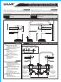 1
1
-
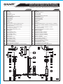 2
2
-
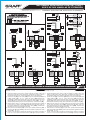 3
3
-
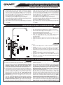 4
4
-
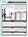 5
5


Graff G-2311-LM40-SN Guía de instalación
- Categoría
- Artículos sanitarios
- Tipo
- Guía de instalación
En otros idiomas
Documentos relacionados
-
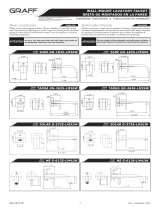 Graff G-6135-LM41W-PC Guía de instalación
-
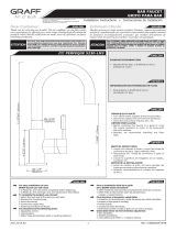 Graff G-5230-LM3 Guía de instalación
-
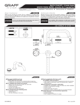 Graff G-6751-C19B Guía de instalación
-
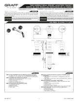 Graff G-11531 Guía de instalación
-
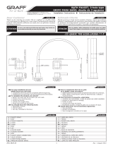 Graff G-6251-LM39B Guía de instalación
-
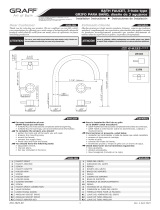 Graff G-6153-LM41B Guía de instalación
-
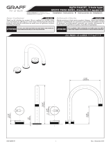 Graff G-11553 Guía de instalación
-
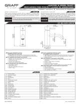 Graff G-6104-LM41M Guía de instalación
-
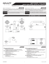 Graff G-11351-LM56B Guía de instalación
-
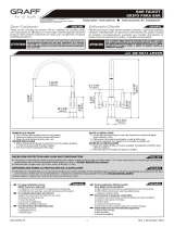 Graff G-5676-LM49D Guía de instalación