
1
Dear Customer Estimado Cliente
Thank you for selecting our product. We are confident we can fully satisfy Muchas gracias por elegir nuestro producto. Estamos seguros que podemos
your expectations by offering you a wide range of technologically advanced satisfacer completamente sus expectativas ofreciéndole una amplia variedad
products which directly result from our many years of experience in faucet de productos tecnológicamente avanzados que resultan direct
amente de
and fitting production. muchos años de experiencia en grifos y su producción apropiada.
ENGLISH
~
ESPANOL
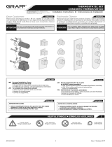
to READ ALL the instructions completely before beginning, LEER TODAS las instrucciones completamente antes de comenzar,
to READ ALL the warnings, care and maintenance information. LEER TODA la información sobre las advertencias,
You should have the following tools: cuidado y mantenimiento.
Usted debe tener las herramientas siguientes:
Hacksaw or Tubing Cu
tter
Sierra para metales o cortatubos
Solder
Suelda
Rags
Trapos
Propane Torch
Soplete de propano
ENGLISH
~
ESPANOL
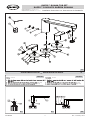
For easy installation of your
Para la instalación fácil de su producto
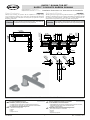
VALVE ROUGH SET CONJUNTO DE VÁLVULAS
JACUZZI product you will need: de la JACUZZI usted necesitará:
® ®
Rev. 1 January 2017
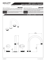
8"
203mm
3/4-14NPT
3/4-14NPT
1-1/4"
32mm
O
1-1/4"
32mm
O
1-1/4"
32mm
O
For care, use soft towel with soap and water only! Under no
circumstances should you use any chemicals.
ATTENTION!
ATENCIÓN!
Para el cuidado, utilice solamente una toalla suave con jabón
y aqua! Bajo ninguna circunstancia no use productos químicos.
1-5/8"
42mm
7-1/8"
181mm
O
O
2
-
3
/
8
"
6
0
m
m
O
2
-
3
/
8
"
6
0
m
m
O
2
-
3
/
8
"
6
0
m
m
2-9/16"
65mm
3-3/16"
82mm
1-1/4"
32mm
2-1/2"
64mm
1-9/16"
(39m
m)
3-1/8"
80mm
2-3/16”
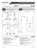
This faucet complies with NSF61/9, ASME/ANSI A112.18.1
and CSA B 125 Standards.
Este grifo se encuentra conforme con losestandares de NSF61/9,
de ASME/ANSI A112.18.1 y de CSA B 125.
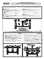
Installation Instructions Instrucciones de Instalación
RAZZO™ ROMAN TUB SET
RAZZO™ CONJUNTO BAÑERA ROMANA
IOG 2892.40
Max.
(
56mm
)
3-3/16"
82mm

2
Rev. 1 January 2017
~
ESPANOL
Please read all instructions before beginning this installation.
Installer to supply 1/2″ Nominal (5/8″ OD) copper tubing.
Shut off the main water supply.
Instructions are given for installations with 8″ (203mm) centres. For
wider installations, adjust all roughing-in dimensions and copper tube
lengths accordingly.
There instructions cover installation on both finished deck or rim
installations and rough/unfinished deck installations.
Please take care while drilling the holes – their diameters cannot
exceed maximum dimensions given in installation instruction.
– the diameter of opening for a spout supply connection shall be MAX
Ø1-1/8” (Ø29mm).
– the diameter of opening for a valve shall be MAX Ø1-1/4”
(Ø32mm).
Leave the protective guard on the spout supply tube until the spout
installation. This is an O-ring sealing surface which may be damaged if
left unprotected.
The installed finished deck material must fit closely to diameters of
plaster guards.
Por favor, lea atentamente las instrucciones antes de comenzar esta
instalación.
El instalador debe proveer el tubo de cobre de 1/2″ nominal (5/8″ D.E.).
Cierre el suministro principal de agua.
Las instrucciones incluidas son para la instalación con centros a 8″
(203 mm). Para instalaciones con los orificios a mayor distancia, ajuste
todas las dimensiones de instalación y las longitudes de los tubos de
cobre según corresponda.
Estas instrucciones cubren la instalación en cubierta acabada o
en
borde e instalaciones en cubierta no acabada.
Cuide que los diámetros de los orificios taladrados no superen las
dimensiones mxi mas inficadas en las instrucciones de montaje.
– diámetro del orificio para el tubo roscado del grifo debe ser de MAX
Ø1-1/8” (Ø29mm).
– diámetro del orificio para la válvula debe ser de MAX Ø1-1/4”
(Ø32mm).
Deje el protector en el tubo de suministro del caño ha
sta instalar el
caño. Ésta es una superficie de sellado de tipo tótico (O-ring) que
puede dañarse si no se protege.
El material de acabado de la cubierta instalado debe quedar muy cerca
de los diámetros de los protectores de yeso.
ENGLISH
1
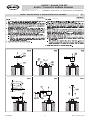
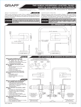
IMPORTANT INFORMATION INFORMACIÓN IMPORTANTE
1.2
1.1
WARIANT 1
Rough/unfinished Deck Installation (to be finally covered with a finish
layer) – see fig. 1.1-1.2.
WARIANT 2
Finished Deck Installation or Rim Mount Installation – see fig.
2.1-2.2.
WARIANT 1
Instalación del conjunto en cubierta acabada „cruda” (finalmente,
cubierta con una capa de acabado) – ver las fig. 1.1-1.2.
WARIANT 2
Instalación del conjunto en cubierta acabada o en borde de la
bañera – ver las fig.2.1-2.2.
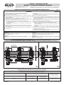
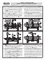
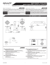
ROUGH/UNFINISHED DECK INSTALLATION (to be finally covered with a finish layer)
INSTALACIÓN DEL CONJUNTO EN CUBIERTA ACABADA „CRUDA” (finalmente, cubierta con una capa de acabado)
Ø5/8" OD
Ø5/8" OD
3/4-14NPT
A
B
MAX 1-1/4" ( 32mm)Ø Ø
MAX 1-1/8"
( 29mm)
Ø
Ø
Hmax = F+1/8"
(4mm)
Hmin = F-1/16"
(1mm)
3/4-14NPT
Ø5/8" OD
Ø5/8" OD
1/2" NOMINAL
COPPER TUBING
2-3/8" (60mm)
for L= 4"
(101.6mm)
L = 4"
(101.6mm)
3/4-14NPT
A
B
MAX 1-1/4" ( 32mm)Ø Ø
MAX 1-1/4" ( 32mm)Ø Ø
2-3/16"
(56mm)
MAX. ~ 1"
(MAX. ~ 25mm)
ROUGH DECK
CUBIERTA NO ACABADO
F = 5/16" - 1-1/4"
(F = 8mm - 31mm)
FINISHED MATERIAL
MATERIAL DE ACABADO
Rough Valve Configuration with Trim Sets
Configuración de válvulas con conjuntos de acabado
Trim Set for Roman Tub
Conjunto para acabado para el conjunto Roman Tub
Model/Modelo
1-3/16” (30mm) 1-3/16” (30mm)
FIG. 1.2, 2.2
Razzo
„A”
±1/16” (±1mm)
„B”
±1/16” (±1mm)
Assembly Dimensions for Faucets Type
Dimensiones de montaje para respectivos tipos de grifos
Assembly of the Valve
according to Detail
Montaje de la válvulas
Assembly Dimensions of Rough Valve Types
Dimensiones de montaje de respectivos tipos de válvulas
This faucet complies with NSF61/9, ASME/ANSI A112.18.1
and CSA B 125 Standards.
Este grifo se encuentra conforme con losestandares de NSF61/9,
de ASME/ANSI A112.18.1 y de CSA B 125.
Installation Instructions Instrucciones de Instalación
RAZZO™ ROMAN TUB SET
RAZZO™ CONJUNTO BAÑERA ROMANA
IOG 2892.40

3
ENGLISH
~
ESPANOL
1
2
3
4
5
6R
6L
7
8
9
10R
10L
11
12
13
14
15
16
17
18
19
20
21
22
23
24
K1
K2
K3
1
2
3
4
5
6R
6L
7
8
9
10R
10L
11
12
13
14
15
16
17
18
19
20
21
22
23
24
K1
K2
K3
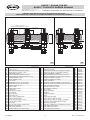
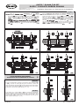
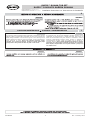
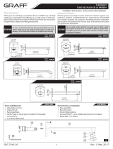
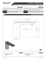
PLASTER GUARD (3 PCS.)
SCREW (2 PCS.)
HEAD SPINDLE ELONGATION (2 PCS.)
VALVE FLANGE / COLLAR (2 PCS.)
FLANGED NUT (2 PCS.)
RIGHT CARTRIDGE (clockwise opening)
LEFT CARTRIDGE (counter-clockwise opening)
RUBBER WASHER (2 PCS.)
METAL WASHER (2 PCS.)
NUT (2 PCS.)
VALVE BODY (2 PCS.) /for cold water/
VALVE BODY (2 PCS.) /for hot water/
COPPER TUBING (2 PCS.)
SPOUT SHANK
O-RING SEAL (4 PCS.)
O-RING SEAL
FLANGE NUT OF SPOUT
PVC WASHER
METAL WASHER
HEXAGONAL NUT
SPOUT SUPPLY CONNECTION
SPOUT PLASTER GUARD
VALVE PLASTER GUARD (2 PCS.)
PLUG OF SPOUT SHANK
SET SCREW
PLUG OF SPOUT SUPPLY CONNECTION
15/64” (2mm) HEX KEY
5/16” (8mm) HEX KEY
SOCKET WRENCH (for ceramic heads)
PROTECTOR DEL YESO (3 PIEZAS)
TORNILLO (2 PIEZAS)
EXTENSIÓN DEL HUSO DE LA CABEZA (2 PIEZAS)
BRIDA DE LA VÁLVULA / COLLARÍN (2 PIEZAS)
TUERCA CON BRIDA (2 PIEZAS)
CARTUCHO DERECHA (se abre hacia la derecha)
CARTUCHO IZQUIERDA (se abre hacia la izquierda)
ARANDELA DE GOMA (2 PIEZAS)
ARANDELA DE METAL (2 PIEZAS)
TUERCA (2 PIEZAS)
CUERPO DE VÁLVULA (2 PIEZAS) /para agua fría/
CUERPO DE VÁLVULA (2 PIEZAS) /para agua caliente/
TUBOS DE COBRE (2 PIEZAS)
TUBO ENROSCADO DEL GRIFO
JUNTA TÓRICA (4 PIEZAS)
JUNTA TÓRICA
TUERCA CON BRIDA
ARANDELA
ARANDELA DE METAL
TUERCA
SUMINISTRO DEL CAÑO
PROTECTOR DEL YESO DE GRIFO
PROTECTOR DEL YESO DE VÁLVULA (2 PIEZAS)
TAPÓN DEL TUBO ENROSCADO DEL GRIFO
TORNILLO DE PRESIÓN
TAPÓN DEL SUMINISTRO DE CONEXIÓN DEL GRIFO
LLAVE ALLÉN 15/64” (2mm)
LLAVE ALLÉN 5/16” (8mm)
LLAVE INGLESA (para cabezas)
2.22.1
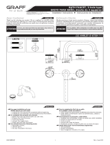
FINISHED DECK INSTALLATION OR RIM MOUNT INSTALLATION
INSTALACIÓN DEL CONJUNTO EN CUBIERTA ACABADA O EN BORDE DE LA BAÑERA
Ø5/8" OD
Ø5/8" OD
3/4-14NPT
A
B
MAX 1-1/4"
( 32mm)
Ø
Ø
MAX 1-1/8"
( 29mm)
Ø
Ø
1/2" NOMINAL
COPPER TUBING
3/4-14NPT
Ø5/8" OD
Ø5/8" OD
2-3/8"
(60mm)
for L= 4"
(101.6mm)
L = 4"
(101.6mm)
3/4-14NPT
A
B
MAX 1-1/4"
( 32mm)
Ø
Ø
MAX 1-1/8"
( 29mm)
Ø
Ø
2-3/16"
(56mm)
FINISHED DECK OR RIM
CUBIERTA ACABADA O EL BORDE DE LA BAÑERA
Rev. 1 January 2017
20
1
2
3
4
5
6L
7
8
9
10L
11
12
13
14
15
16
17
18
19
21
22
23
24
K1
K2
K3
2824660
9903378
2806980
2824640
2038310
2038320
2806800
2806810
2806790
2824570
2824580
2824680
9917119
2824710
2002930
2005480
2005490
2824700
2824720
2824650
2824750
9903293
2824740
9919050
9919057
2241455
2824630
6R
10P
9917290
not included
This faucet complies with NSF61/9, ASME/ANSI A112.18.1
and CSA B 125 Standards.
Este grifo se encuentra conforme con losestandares de NSF61/9,
de ASME/ANSI A112.18.1 y de CSA B 125.
Installation Instructions Instrucciones de Instalación
RAZZO™ ROMAN TUB SET
RAZZO™ CONJUNTO BAÑERA ROMANA
IOG 2892.40

4
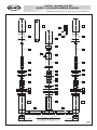
3
K1
K2
K3
23
12
15
16
17
18
19
1
22
24
20
13
13
14
11 11
9
10L
21
1
2
3
4
5
6L
7
8
9
10R
21
1
2
3
4
5
6R
7
8
3/4-14NPT 3/4-14NPT
2-3/8"
(60mm)
for L= 4"
(101.6mm)
1/2" NOMINAL COPPER TUBING (5/8" OD)
TUBO DE COBRE DE 1/2" NOMINAL (5/8" D.E.)
Rev. 1 January 2017
This faucet complies with NSF61/9, ASME/ANSI A112.18.1
and CSA B 125 Standards.
Este grifo se encuentra conforme con losestandares de NSF61/9,
de ASME/ANSI A112.18.1 y de CSA B 125.
Installation Instructions Instrucciones de Instalación
RAZZO™ ROMAN TUB SET
RAZZO™ CONJUNTO BAÑERA ROMANA
IOG 2892.40

5
ESPANOL
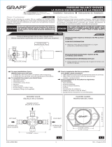
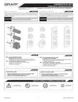
1. Prepare the installation openings of dimensions given in the fig. 1.1
and 2.1.
2.
the lower nut (18) on the spout supply connection (19) and
put the metal (17) and
(16) washers on (fig. 4).
3.
(9) on the valves (10L) and (10R) and put
the metal washers (8) and the rubber washers (7) (fig. 4).
4.
(11) with dimensions
according to valve (10L), (10R) axis and the spout supply (19)
spacing. Put the tubes inside
openings in the valves (10L) and
(10R) and in spout supply connection (19) (fig. 4).
Then insert the valves and spout supply ready for installation (with
the copper tubes (11) inserted) into the prepared openings below
the installation surface (see fig.
or
case of Rough/unfinished Deck Installation:
installation:
the following equation to calculate the of the finish layer in
order to execute the spout
installation in a proper way:
the of the finish layer with B dimension (required
between finished surface level and the upper surface of the spout
(see fig. 1.2)
finish material B dimension height
alves installation:
the following equation to calculate the of the finish layer in
order to execute the valves installation in a proper way:
the of the finish layer with A dimension required
between finished surface level and the upper surface of the head
spindle elongation piece (see fig. 1.2)
1. Prepare los orificios de montaje de dimensiones indicadas en las fig.
1.1 y 2.1.
2. Enrosque la tuerca inferior (18) en el suministro del caño (19),
meta la arandela de metal (17) y el taco
(16) (fig. 4).
3. Enrosque las tuercas inferiores (9) en las válvulas (10L) y (10R),
meta las arandelas de metal de apriete (8) junto con las arandelas
de goma (7) (fig. 4).
4. Prepare dos tubos de cobre
.E.) (11) de las
dimensiones conformes al espaciamiento de los ejes de las válvulas
(10L), (10R) y el suministro del caño (19).
los tubos en
los orificios
que se encuentran en las válvulas (10L) y (10R) y
en el suministro del caño (19) (fig. 4).
Las válvulas preparadas de este modo y el suministro del caño con
los tubos de dobre introducidos (11) meta desde abajo de la
superficie de acabado en los orificios preperados (fig.
o
Para la Instalación del Conjunto en cubierta no acabada:
de la conexión del caño:
Aplique la fórmula siguiente para calcular el grosor de acabado para que
se pueda instalar la conexión del caño del modo correcto.
Añada el grosor de acabado a la dimensión B requerida entre la
superficie de acabado y la superficie superior de la conexión del caño
(ver la fig. 1.2).
Placas/Material de la superficie de acabado
B Altura de la
instalación
de las válvulas:
Aplique la fórmula siguientes pata calcular el grosor de acabado para que
se pueda instalar las válvulas del modo correcto.
Añada el grosor de acabado a la dimensión A requerida entre la
superficie de acabado y la superficie superior de la extensión del huso
(ver la fig. 1.2).
ENGLISH
2
ROUGH INSTALLATION INSTALACIÓN DEL CONJUNTO
Rev. 1 January 2017
ESPANOL
ENGLISH
1
1
1
18
19
8
9
1 L
8
9
1
11 11
19
4
12
4
1 L 1
6.1
5.1
4
This faucet complies with NSF61/9, ASME/ANSI A112.18.1
and CSA B 125 Standards.
Este grifo se encuentra conforme con losestandares de NSF61/9,
de ASME/ANSI A112.18.1 y de CSA B 125.
Installation Instructions Instrucciones de Instalación
RAZZO™ ROMAN TUB SET
RAZZO™ CONJUNTO BAÑERA ROMANA
IOG 2892.40

1
12
9 9
18
3 3
2
2
A
B
(10L) (10R)
(19)
(10L)
(10R) y del suministro del caño (19)
Rev. 1 January 2017
case of Rough/unfinished Deck Installation: the
flange nut of the spout (15) from the top onto the spout supply
connection (19) before laying the finish layer and screw the flange
nuts (5) on the valves (10L) and (10R). Adjust the position of the
spout supply connection (19) by means of the nut (18) and the
spout
(12) and the position of valves (10L) and (10R) by
means of the nuts (9) and flange nuts (5) (see fig.
in order to
obtain the appropriate values of A and B after laying of the finish
layer.
case of Finished Deck Installation or Rim Mount
Installation:
the spout (12) from the top into the
spout supply connection (19) and screw the valve flanges (4) on
the valves (10L) and (10R) (see fig.
Adjust the position of the
spout supply connection (19) by means of the nut (18) and the
spout
(12) and the position of valves (10L) and (10R) by
means of the nuts (9) and flanges (4) (see fig.
in order to
obtain the appropriate values of A and B.
Para la Instalación del conjunto en cubierta no acabada: Antes
de instalar la capa de acabado desde arriba en el suministro del caño
(19) enrosque la tuerca de brida del caño (15), y en las válvulas
(10L) y (10R) enrosque las tuercas de brida (5) (fig. 4). Mediante
la tuerca (18) y el tubo de conexión del caño (12) ajuste la posición
del suministro del caño (19), y mediante las tuercas (9) y los
tuercas de brida (5) la posición de las válvulas (10L) y (10R)
(fig.
del modo que, tras instalar la capa de acabado, se
obtengan los respectivos valores de las dimensiones A y B.
Para la Instalación del conjunto en cubierta acabada o
borde de la
: arriba en el suministro del caño (19)
enrosque el tubo de conexión del caño (12), y en las válvulas (10L)
y (10R) enrosque los collarines de las válvulas (4) (fig.
Mediate la tuerca (18) y el tubo de conexión del caño (12) ajuste la
posición del suministro del caño (19), y mediante las tuercas (9) y
los collarines (4) la posición de las válvulas (10L) y (10R) (fig.
a fin de obtener los respectivos valores de las dimensiones A y B.
ESPANOL
ENGLISH
A
B
(10L) (10R)
(19)
(10L)
(10R) y del suministro del caño (19)
23
1
4
9
18
22
22
21
19
22
1 L 1
23
1
22
ESPANOL
ENGLISH
the copper tubes (11).
8.
the water supply to the threaded ferrule connections of the
valves (10L) and (10R), bearing in mind that the hot water should
be connected to the valve
ed with red label, whereas the cold
water should be connected to the valve
ed with blue label.
9. Flush the installation with water in order to remove any dirt.
ealice la suelda de los tubos de cobre (11).
8. A los tubos roscados de las válvulas (10L) y (10R) conecte el
suministro de agua, sin olvidar de conectar el suministro del agua
caliente a la válvula indicada con etiqueta
oja, y del agua a la
válvula indicada con etiqueta
9. Aclare la instalación a fin de
eliminar
5.2
6.2
5.3 6.3
Rough/unfinished Deck Installation:
ey (K2) install the plug (25) onto the spout supply connection
(19) from the top. Then rotate the valve head spindle elongations
(3) carefully to open the valves (10L) and (10R): in case of hot
water valve rotate the elongation counter
whereas in
case of cold water
rotate it the entire system for
potential
case of tightness, close the (10R) and (10L)
valves and place the guards (21) and (22) on the threaded parts of
the spout supply connection (19) (see fig.
Then you may lay
the finish layer.
the finish layer is completely dry you may
remove the guards (21) and (22) (see fig.
emove the plug
(25) using the Allen
ey (K2). the spout (12) onto the
spout supply connection (19) and the valve flanges (4) onto the
valves (10L) and (10R) (see fig.
Put the guards (1) on the
valves and spout
from the top (see fig.
1 .1. Para la Instalación del conjunto en cubierta no acabada: En el
suministro del caño (19), desde arriba enrosque el tapón (25)
usando la llave (K2). Abra las válvulas (10L) y (10R) girando con
cuidado las extensiones de los husos de las válvulas (3): en sentido
antihorario para la válvula del agua caliente, en sentido horario para
la válvula del agua fr
a. ompruebe si no hay ninguna fuga. i no las
hay, cierre las válvulas (10R) y (10L), en los elementos roscados
del suministro del caño (19) y de las válvulas (10L) y (10R) meta
los protectores (21) y (22) (fig.
.3). A continuación, instale la capa
de acabado.
na ve secada la capa de acabado, quite los protectores
(21) y (22) (fig.
.4). esenrosque el tapón (25) usando la llave
(K2). En el suministro del caño (19) enrosque el tubo de conexión
del caño (12), y en las válvulas (10L) y (10L) los collarines de las
válvulas (4) (fig.
. ). esde arriba meta los protectores (1) en las
válvulas y el tubo de conexión del caño (fig.
. ).
6
This faucet complies with NSF61/9, ASME/ANSI A112.18.1
and CSA B 125 Standards.
Este grifo se encuentra conforme con losestandares de NSF61/9,
de ASME/ANSI A112.18.1 y de CSA B 125.
Installation Instructions Instrucciones de Instalación
RAZZO™ ROMAN TUB SET
RAZZO™ CONJUNTO BAÑERA ROMANA
IOG 2892.40

1 1
1
1 11
2
3
3
L
Rev. 1 January 2017
21 2 21
4
12
19
4
1 L 1
ESPANOL
ENGLISH
5.4
6.4
5.5
5.6
7.1
7.2
ESPANOL
ENGLISH
In case of contamination, damage or wear of the valve cartridge ((6L)
or (6R)) unscrew the screw (2) using the screwdriver, remove the
valve head spindle elongation (3) and then dismount the valve cartrid-
ge by means of the Allen Key (K3). For installation of the valve cartrid-
ge proceed in the reverse order (see fig. 7.1, 7.2).
Si la cabeza de la válvula (6L) o (6R) se encuentra contaminada,
dañada o gastada, usando el destornillador plano se debe desenroscar
el tornillo (2), quitar la extensión del huso de la válvula (3), y luego
usando la llave (K3), desenroscar la La instalación de la se hace en
orden contrario (ver la fig. 7.1, 7.2).
VALVE CARTRIDGE REPLACEMENT
SUSTITUCIÓN DE LA CABEZA DE LA VÁLVULA
3
case of Installation or Mount
Installation: Put the supply plug
on the spout and tight
the screw using the Allen ey . Then rotate the valve head
spindle elongations
carefully to open the valves and
: in case of hot water valve rotate the elongation counter-
whereas in case of cold water rotate it
the and valves, disassemble the supply plug (fig.
and place the guards on the valves and the spout
(fig.
Para la Instalación del conjunto en cubierta acabada o en
borde de la bañera: Meta el tapón de suministro
en el tubo
roscado del grifo, enrosque el tornillo usando la llave .
Abra las válvulas
y girando con cuidado las
extensiones de los husos de las válvulas
: en sentido antihorario
para la válvula del agua caliente, en sentido horario para la válvula
del agua
si no hay ninguna fuga. no las hay,
cierre las válvulas
y , desmonte el tapón de suministro
(fig. luego desde arriba meta los protectores en las
válvulas y el tubo de conexión del caño (fig.
7
This faucet complies with NSF61/9, ASME/ANSI A112.18.1
and CSA B 125 Standards.
Este grifo se encuentra conforme con losestandares de NSF61/9,
de ASME/ANSI A112.18.1 y de CSA B 125.
Installation Instructions Instrucciones de Instalación
RAZZO™ ROMAN TUB SET
RAZZO™ CONJUNTO BAÑERA ROMANA
IOG 2892.40

7
IOG 2892.40
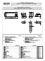
1-5/8"
42mm
2-3/8"
60mm
Ø
1-1/2"
39mm
2-1/2"
64mm
3-1/8"
80mm
3-3/16"
80mm
1/4"
6mm
1-1/4"
32mm
2-3/8"
60mm
Ø
9-3/16"
233mm
7-1/8"
181mm
2-9/16"
64mm
16°
BATH FAUCET, 3-hole type
GRIFO PARA BAÑO, diseño de 3 agujero
Rev. 1 January 2017
ENGLISH
~
ESPANOL
This faucet complies with NSF61/9, ASME/ANSI A112.18.1
and CSA B 125 Standards.
Este grifo se encuentra conforme con losestandares de NSF61/9,
de ASME/ANSI A112.18.1 y de CSA B 125.
Installation Instructions Instrucciones de Instalación
RAZZO™ ROMAN TUB SET
RAZZO™ CONJUNTO BAÑERA ROMANA
ENGLISH
~
ESPANOL
1
2
3
4
5
6
7
8
9
10
11
12
13
2892500
9903159
5120900
2892100
5108300
2834170
2806640
9903293
9917040
9916033
9917465
2398215
9903273
A
K1
13
13
2824680
9919050
K2
SPECIAL KEY FOR THE AERATOR K2
LLAVE ESPECIAL PARA EL AEREADOR
K2
2206895

8
8
4
4
8
8
7
7
6
6
3
5
5
9
9
10
12
12
12
10
IOG 2892.40
Rev. 1 January 2017
11
13
This faucet complies with NSF61/9, ASME/ANSI A112.18.1
and CSA B 125 Standards.
Este grifo se encuentra conforme con losestandares de NSF61/9,
de ASME/ANSI A112.18.1 y de CSA B 125.
Installation Instructions Instrucciones de Instalación
RAZZO™ ROMAN TUB SET
RAZZO™ CONJUNTO BAÑERA ROMANA
9.1 9.2 9.3
9.1-9.3
9.1-9.3
(fig. 9.1).
(fig. 9.2).
(fig. 9.3).
(fig. 9.1)
(fig. 9.2)
(fig. 9.3)
ENGLISH
~
ESPANOL
4
FAUCET INSTALLATION INSTALACIÓN DEL GRIFO
K2

9
IOG 2892.40
10.1-10.6 10.1-10.6
10.1
10.2
10.1
10.2
(fig.
10.3
).
(fig.
10.6)
.
(fig.
10.4
),
(fig
10.5)
.
(fig.
10.6
).
(fig.
10.3
).
(fig.
10.4
)
(fig.
10.6
).
(fig
10.5
).
(fig.
10.6
).
10.1
10.4
10.2
10.5
10.3
10.6
Rev. 1 January 2017
5
LEVER INSTALLATION
INSTALACIÓN DE LA PALANCA
ESPANOL
ENGLISH
This faucet complies with NSF61/9, ASME/ANSI A112.18.1
and CSA B 125 Standards.
Este grifo se encuentra conforme con losestandares de NSF61/9,
de ASME/ANSI A112.18.1 y de CSA B 125.
Installation Instructions Instrucciones de Instalación
RAZZO™ ROMAN TUB SET
RAZZO™ CONJUNTO BAÑERA ROMANA

10
This faucet complies with NSF61/9, ASME/ANSI A112.18.1
and CSA B 125 Standards.
Este grifo se encuentra conforme con losestandares de NSF61/9,
de ASME/ANSI A112.18.1 y de CSA B 125.
Installation Instructions Instrucciones de Instalación
IOG 2892.40
8
8
6
8
CARE AND MAINTENANCE
CUIDADO Y MANTENIMIENTO
Your Jacuzzi product is designed and engineered in accordance with the
highest quality and performance standards. Be sure not to damage the
finish during installation. Care should be given to the cleaning of this
product. Although its finish is extremely durable, it can be damaged by
harsh abrasives or polish. Never use abrasive cleaners, acids,
solvents, etc. to clean any Jacuzzi product. To clean, simply wipe
gently with a damp cloth and blot dry with a soft towel.
Su producto de la Jacuzzi está diseñado y dirigido acuerdo con los
estándares de funcionamiento y calidad más altos. Este seguro no
dañar las terminaciones del grifo durante la instalación. Cuide el
producto manteniendolo siempre limpio. Aunque su acabado es
extremadamente durable, puede ser dañado por los abrasivos o
pulientes ásperos. Nunca utilice limpiadores abrasivos, ácidos,
solventes, etc. para limpiar cualquier producto de la Jacuzzi.
Para limpiar, simplemente use un paño húmedo y seque con
una toalla suave.
®
®
®
®
7
RAZZO™ ROMAN TUB SET
RAZZO™ CONJUNTO BAÑERA ROMANA
Rev. 1 January 2017
ESPANOL
ENGLISH
ESPANOL
ENGLISH
ESPANOL
ENGLISH
-
 1
1
-
 2
2
-
 3
3
-
 4
4
-
 5
5
-
 6
6
-
 7
7
-
 8
8
-
 9
9
-
 10
10
-
 11
11


Jacuzzi MX88826 Guía de instalación
- Tipo
- Guía de instalación
- Este manual también es adecuado para
En otros idiomas
- English: Jacuzzi MX88826 Installation guide
Documentos relacionados
Otros documentos
-
 Graff G-6751-C19B Guía de instalación
-
 Graff G-11553 Guía de instalación
-
 Graff G-11351-LM56B Guía de instalación
-
 Graff G-6865-BNI Guía de instalación
-
 Graff Faucets G-7005 Guía de instalación
-
 Graff G-3896-C2 Guía de instalación
-
 Graff G-2311-LM40-SN Guía de instalación
-
 Graff Faucets G-6300-LM42-PC Guía de instalación
-
 Graff G-8052S Installation Instructions Manual
-
 Graff G-8053S Guía de instalación


