


The
Porsc
he
912
E
..
.
The techni
ca
l
spec
ificat ions are
as
follows:
Capacity:
1971 cm
3
Stroke:
71
mm
Bore:
91
mm
Horse power:
developed at:
Torque:
develo
ped
at:
86
hp/64
4900 rpm
98
Ibft/133
4000 rpm
.
..
is
equipped
with
..
.
. . . a
2
Itr
., 4 cylinder engine (similar to that in the
Type
This
motor
has
been
fitted
with
the electronically controlled AFC fuel injection thermal reactors
and
exhaust
gas
recirculation .

.
· . . a 5
speed
transmission
(based
on transmission
type
915)
with
modified transmission ratio
and a newly designed clutch operation mechanism.
·
..
a like the 911, a dual-circuit brake system,
disks brakes
without
"inner
ventilation"
.
·
bodywork
similar
to
the 911
but
with
permanently
fixed rear side windows as we
ll
as
other
minor
changes.
2

10
ENGINE
CRANK
CASE,
CYLINDERS,
ENGINE
MOUNTS
The crank
case
and the cylinders
are
the
same
as
in the engine
type
914/2
.0 Itr.
The following
is
new:
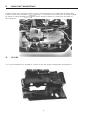
The engine mount.
It
consists
of
a swung steel bar which
is
secured
to
the
motor
in the
same
way
as
in the 914.
The mounting points on the
chassis
were moved outwards
to
the wheel wells however.
Warning:
installing the
motor
mount, note that the casted in part number (arrow)
is
pointing toward
t
he
rear.
3

13
CRANK
SHAFT
DRIVE/PISTONS
All
parts
of
the crank shaft drive
are
the
same
as
in the basic motor.
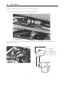
An
additional fan-belt
pulley
is
fitted
to
drive the secondary air pump. It
IS
secured to the
front
of
the air intake housing
by
means
of
a
thr
ee-armed block and
is
driven by
means
of
a shaft
from
the center
of
the cooling fan .
19
COOLI
NG
The
eng
ine sh
ee
tmetal w
as
changed
to
conform
to
the
911
engine compartment configuration .
4

20
FUEL
SUPPL
V
The
912
E
is
fitted
with
an
80 Itr. (inc!. 8 Itr. reserve) fuel tank.
The fu
el
pump
is mounted on the
front
ax le aux il iary mount.
The fuel
filter
is the
same
as
in the CIS injection
It
is
secured
to
the l
eft
-h
and wheel well in the
engine compartment
1
1.
) Fuel
tank
2.)
Fuel
pump
3.
) Fuel
filter
4.)
Pressure
regulator
5
.)
Injection
valv
es
6.)
Cold start
valve
5

24
EL
ECTRONIC
F
UEL
INJECTION
-
AFC
The Porsc
he
912 E
is
equipped
with
a
motor
that
has
a air
flow
controlled electronic fuel injection .
Before we describe this
unit
in detail, a few words about the accelerator cable.
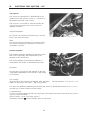
The
accel
era
tor
cable
is
in
two
parts. The connector (arrow)
is
located
within
the engine compart-
ment behind the rear panel
and
is
accessible when the cover
to
the guide channel
is
removed.
Construction
and
funct
ion of the
ATC
injection
The component parts
1 Fuel Tank
2 Fuel Pump
3 Fuel Filter
4 Cold Start Valve
6 5 Fuel Injector
6
Pressure
Regulator
7
Auxiliary
Air
Regulator
8
Throttle
Switch
9
Air
Filter
10
Temperature
Sensor
II
11
Battery
12
Ignition Switch
A Int
ak
e-air
Sensor
B
Throttle
valve
C
Air
Sensor
Flap
o
Co
ntrol Unit
Principles
of
Operation
The amount
of
fuel
that
is
to
be
used
is
determined
by
the vo lume
of
intake air
and
the
speed
of
the
motor.
The injector sequence
is
determi
ne
d
by
th
e igni
tion
dis
tr
ibu
tor
breaker points.
The fuel required
for
cold starting
is
injected by the electro-magnetic cold start valve.
Warm-up
en
richment
of
t
he
fuel
mixture
is
via t he
au
xiliary air regulator in conjunction
with
the
temperature s
ens
or I in the in take-air
Se
n
so
r housing and t
he
temperature sensor II in the cylinder
head.
Fuel mixture enrichme
nt
for
full
load condi tio
ns
is
by
me
a
ns
of
a
throttle
switch.
6
2

.
24
ELECTRONIC
FUEL
INJECTION
-
AFC
Description
Intake-Air
Sensor
The intake-air sensor
is
located
in
the engine compartment at the right-hand side between the air
filter
and the
throttle
housing (L) .
Construction
Aluminum
housing (A)
with
Bye-pass channel (5)
and
Adjustment
screw (6)
Air
sensor flap (1)
with
Back pressure valve (8)
and Damping vane (2)
Damping chamber (7)
Return spring (9)
Potentiometer
(B)
with
Pump contacts
(C)
Temp
era
ture sensor I (D)
Operation
The volume
of
air that the
motor
can
draw in
is
determined
by
the position
of
the thro
ttle
valve.
The resultant air
flow
causes
the sensor flap
to
deflect against the return spring. T
he
flap deflection
is
transmitted via a shaft
to
the potentiometer which supplies a specific voltage
to
the con
trol
unit. The
temperature sensor I
is
connected
to
the potentiometer and influences the control signal volta
ge.
The injector which
is
activated by the control
unit
injects
an
exact amount
of
fuel appropriate
to
the
volume
of
intake-air.
The damping vane
is
designed
to
minimize sensor flap hunting. The
function
is
as
follows:
with
deflection
of
the flap the damping vane
is
forced
into
the damping chamber. The resultant compressed
air
within
the chamber
can
escape
only
through the
release
slit
(S)
. Sudden movements
and
hunting
is
thereby reduced.
A fraction
of
the air intake
is
detoured around the sensor flap via the bye-pass channel. The fuel-air
mixture
for
idle
can
be
set
by
means
of
the adjusting screw (6).
A pump contact
is
located
within
the potentiometer.
When
the sensor flap
is
deflected open the pump
contact
is
closed and the fuel pump started .
Prob l
em
condition:
Motor
does
not
start; starting
dif
ficulties;
low
efficiency.
Troubleshooting :
Remove the plug connected
to
the potentiometer on the intake-air sensor. Connect
an
ohm meter
between the contacts 6 and
9.
value: 200
to
400
Mea
sure between contacts 7
an
d 8.
Nominal value: 120
to
200
7
\
4

~
---
.
---.------.
"
-,
24
ELECTRONIC
FUEL
INJECTION
-
AFC
Throttle Switch
This switch provides the control
unit
with
necessary
information
for
mixture
enrichment and
full
load
cond itions.
It
is
not
necessary
to
adjust this switch.
Problem
condition:
Low
engine power
Troubleshooting:
Disconnect the wires
from
the switch and connect
an
ohm meter between contacts 3 and 18.
Slowly
open the
throttle
valve. The resistance must change
from
00
to
0
Ignition Distributor
The ignition
distributor
provides the control
unit
with
information
concerni
ng
the
speed
of
the
engine (rpm) and sequen
ce
for
activating the fuel injectors.
Operation
In addition
to
de
livering impulses
to
the ignition coil,
the contact breaker points
also
supply impul
ses
to
th
e control unit.
Each
impulse (1)
is
converted
to
a
squ
are wa
ve
(2)
within
the
control
unit
. These
sq
uare wave impulses are then presented to a gate (3)
which provides a single
pu
Ise
output
for
each
sequ
ence
of
four
input
pu
Ises
which are the
resu
It
of
t
wo
re
volutions
of
the
motor
crank shaft. That
is,
f
ollowi
ng
each
revolu
tion
of
the crank shaft all
fo
ur
fuel injectors
hav
e received
an
ac
tivat
ing
impulse (5
).
Thus the fuel injectors inject a de
fin
ite
amount
of
fuel independent
from
the position
of
th
e air sensor flap. The injected fuel
is
always half
of
the amount necessary
for
the correct fuel
mix
ture. Si
nce
the crank shaft turns
tw
i
ce
for
each
cycle,
two
injector sequences
are
put
into
operation
thus
each
cylinder receives the
full
amount
of
fuel
for
each
firing stroke.
o
Zyl. 1
Zy
l.4
Zyl. 3
Zyl.2
1 breaker
im
pulses
-
--t-
2 imp
ul
se
shaper
3 frequency
d
ivid
er
4 air
flow
senso
r
fla
p position
(pot
entiom
eter)
'5
injection i
mpul
(duration
of
injection)
su
ct
ion
compressi
on
ign
it
ion
exhaust
o crankshaft angle
360
7
20
·
I
:
control
unit
(e
lectronic)
8

. .
24
ELECTRONIC
FUEL
INJECTION
-
AFC
Temperature Sensor I
The temperature sensor I
is
located in the intake air sensor housing
and
permanentely installed.
It
can
not
be
replaced separately. Its
function
is
to
measure the temperature
of
the intake air and
provide the
control
unit
with
the appropriate
information
.
Troubleshooting:
Simi lar
to
the intake-air sensor.
Temperature Sensor
II
This sensor
is
located in the cylinder head.
It
provides the control
unit
with
information
concerning
engine temperature
and
thus about the starting and warm-up enrichment.
Problem condition: the
motor
does
not
start; warm starting difficulties;
motor
starts
but
stops again
almost at once; fuel consumption
too
high;
CO
value
is
too
high in slow running.
Troubleshooti
ng
:
Connect
an
ohm meter between temperature sensor II
and
ground.
Nominal value at
20°C/68°F
motor
and ambient temperature:
1.5
to
2 the
motor
temperature
is
above
80°CI176°F
the value must
be
less
than
300
9

24
ELECTRONIC
FUEL
INJECTION
-
AFC
Cont
ro
l Unit
The control u
nit
is
located in the engine compartment
within
a cavity welded
to
the right-hand wheel
well.
The contro l
unit
proc
es
s
es
information
concerning
the
fo
llowing:
Volume
of
intake air
Temperature
of
i
nt
ake a
ir
Motor
rpm
Motor
temperatu
re
Intake air sensor deflec
tion
(fu ll load)
It
determi
nes
an
d c
ontro
Is
th
e injection sequence and
duration.
The electronic con
tro
l unit
is
composed
of
printed
circuits and
int
egrated circu
it
components.
It
is
fitted
wi
th app
rox
imately 80 components.
The printed ci rcu
it
board
is
secured
to
the
control
unit
and
presse
d in
to
the socket
until
a spring
snaps
into
place.
Code explanation:
A Control un
it
1 Control mul
ti
vibrator
1a Impul
se
an
d rpm divider
2
Multipl
ier st
age
2a
Warm-up enrich ment
3
Output
st
a
ge
4 Fuel injector
5
Series
resistor
I Control voltage from intake-air
se
ns
or
la Control impulse from
distributor
contact breaker
point
s
II Control signal
from
throttle
switch
Iia Control voltage
from
starter swit
ch/
temperature sensor II
10

-
24
ELECTRONIC
FUEL
INJECTION
-
AFC
Fuel Injector
The volume
of
injected fuel
is
determined by the
length
of
time the injector
is
open (i.
e.
the time
of
the impulse
from
the control
unit).
The injector
is
connected
to
+ via the resistor (R).
(The contro l signal
from
the control
unit
is
of
negative potential.)
Injection Sequence
All
injectors
are
activated simultaneously, once
for
every crank shaft revolution.
Note:
The plug and socket assembly
is
so
arranged that
it
can
not
be
inadvertanly connected
to
an
injector
of
the
MPC
injection.
Pressure Regulator
The pressure regulator regulates the pressure
of
the
fuel in the ring supply line independent
of
the
pressure in the vacuum line.
The spri
ng
chamber
of
the
pressu
re
regu
lator
is
connected to the intake air
distributor
via a
hose
.
Operation
By using this configuration the pressure
of
the fuel
is adj usted independent
of
the vacuum in the intake
air
distributor.
For example
High vacuum in the intake air
distributor
(idle operation) -
low
fuel pressure. L
ow
vacuum in the
intake air
distributor
(full load) - high fuel pressure.
This way, the difference between fuel pressure and intake air
distributor
pressure always remains
the
same
for
all load conditions
of
the engine.
Troubleshooting :
Connect a
pr
essur
e
gauge
into
the ring supply line. Disconnect the vacuum
hose
from
th
e pressure
reg
ulator. Start the
motor
.
Nominal value: 2.5 bar (36.75
psi
approx.)
Reconnect the
hose
the fuel pressure must now
be
lower.
11

24
ELECTRONIC
FUEL
INJECTION
-
AFC
Auxiliary Air Regulator
The engine requires during the warm-up
phase
a
richer
mixture
. The increased volume
is
determined
by
the
control
unit
(signal
from
temperature sensor
II). The additional volume
of
air required
for
this
purpose
is
regulated
by
the
auxiliary
air regulator
and detoured around the
throttle
valve
into
the
intake air distributor.
Construction
The
auxiliary
air regulator consists
of
a slide valve
and a bi-metal spring which
is
enclosed
by
an
electrical heating coil.
Operation
If
the engine
is
cold, the auxiliary air slide valve
is
fully
open. When the ignition switch
is
turned on
the heating coil starts
to
warm up. With increase
in temperature the bi-metal spring becomes weaker
and
the slide valve slowly shuts
off
the air intake.
Troubleshooting:
Electrical : Disconnect the plug
to
the auxiliary
air regulator. Connect
an
ohm meter.
Nominal value: approx. 30.
Mechanical : Remove
hose
from
the intake manifold
and
throttle
housing.
Blow
air
thru
from
one side.
If
the
motor
is
cold
the air must
flow
freely. Switch on
the ignition, continue
to
blow
air
thru
and observe that the air
flow
becomes
restricted
with
increase in temperature.
.b
-
12

t
24
ELECTRONIC
FUEL
INJECTION
-
AFC
Troubleshooting:
Thermo
switch: Engine temperature under
10°C/
50°F.
Remove the plug
from
the
cold start valve and connect a
test lamp. Disconnect the
wire
from
contact
1 on the
ignition
coil. Operate the starter
motor
:
the test lamp must
initially
be
bright
and then
visibly
darker
within
not
less
than
11
seconds.
Cold start valve : Connect a pressure gauge
to
the
ring
supply
line.
Operate the starter
motor
in
order
to
reduce the fuel pressure.
Remove the plug
from
the cold
start valve. Conne
ct
the
cold
start valve
by
means
of
extra
wi
res
to
ground and
contact
15
on the
ignition
coil.
Turn
on the
ignition
switch
--
the fuel pressure
must fall.
Cold Starting Valve
The cold starting valve
is
located in intake air
distributor
and
is
activated
by
a
thermo
time
switch
which
is
located adjacent
to
the intake air
distributor.
Here are a
few
tips concernig
trouble
free
operation
of
engines equipped
with
AFC
injection
.
All
ai
r lines and hos
es
and the intake
-ai
r sensor must be absolutely air
tight
. The sensor flap must be
able to move
fr
e
ely
over its entire range and
not
stick at any
point.
All
e
le
ctrical connections must
be
tight
and free
of
corrosion .
Plug and socket
color
code: Fuel
injector
:
white
Cold start valve:
blue
Thermo
time
switch :
brown
Intake-air sensor:
black
When the vacuum line
is
disconnected, the fuel
pr
ess
ure must be
about
36
psi.
Ignition
timing
and vaive
adjustment
must
be
correct.
For
idle and
CO
adjustment
:
Idle
is
by
adjusting the screw on t
he
throttl
e housing.
Nom
in
al
v
al
u
e:
925
± 50
rpm
The CO value
is
fa
cto
ry
adjusted
by
me
ans
of
the bye-p
ass
a
dj
ustme
nt
screw in the intake-air sensor
housing.
The
posi
tion
of
this
screw should be altered o
nly
when
the
no
minal value
of
0.5 - 1.2 %
CO
ca
n
no
t
be
obtained inspite
perfect
wo
rkin
g order
of
th
e engine.
The CO-adjustment
sc
rew
is
covered
by
a plug. (Part No.
923.606
.991 .01)
Pl
ug col
or
code:
Bl
ack: Bo
sc
h setting
Blue: Pr
oduction
setting
Red: Service s
etti
ng
13

CIRCUIT
DIAGRAM
FOR
THE
AFC
INJECTION
1
Multipo
le
plug
2 Ignition coil
3
Throttle
switch
4 Intake-air Sensor
5 Temperature
sensor
II
6 Cold start valve
7 Thermo
ti
me
switch
8 Fuel pump
9 Ground connection (Gnd)
10 Double relay
11
Auxiliary
air regulator
12
Series
resistor
13 Battery
14 Fuel injector cyl. 1
15 Fuel injector cyl. 2
16 Fuel
injectorcyl.
3
17
Fuel injector cyl. 4
Test
Values
4.
Intake-air
Sensor
: pin 6 + 9 = 200 - 400
pin 7 + 8 = 120 - 200
pin 36 + 39 = 0
Air
sensor
flap =
00
pin
27
+ 6 = 8 -
11
k
at
100C
(50°F)
2 - 3 k
at 20°C (68°F)
- 2 k
at
50°C (122°
F)
3.
Throttleswitch: pin 3 + 18,
throttle
open =
00
to 0
5. Temper
at
ure
sensor
II: at approx. 20°C (68°
F)
approx. 2.5
Pin
13 +
49
at approx. 80°C (176°F) below 300
6.
Cold start
valve
: pin 45 + 46 = 4
7. Thermo time switch:
below + 30°C (86°
F)
above
+ 40°C (104°
F)
Pin
G +
Gnd
25 - 40
50
- 80
Pin
Wt
Gnd
100 - 160
Pin
G + W
25 - 40 50 - 80
1
0.
Double relay :
pin85+86b=
50
- 100
12. Seriesresistor : pin 43 + Gnd. =
5-
14. -
17
. Fuel injector:
pin 14 + 41/32 + 40/33/38115 +
37
= 2 - 3
14

26
EXHAUST
SYSTEM
The
912
E engines
are
equipped
with
a secondary air injection, thermal reactors and EGR.
The
muffler
and heat exchangers
are
also new.
The secondary air injection and the thermal reactors are designed
to
reduce the
CO
and
HC
emission
in the exhaust. The purpose
of
the EGR
is
to
reduce the emission
of
nitric
oxide (NO
x
).
Secondary
Air
Injection
The air required
for
after burning the exhaust
gases
is
supplied
to
the exhaust manifold by means
of
a
motor
driven air pump.
The air
from
the pump (1)
is
pumped via a back-up
valve (2) and a
distributor
line (3)
to
the air
injection valve (4) which
is
located immediately
behind the exhaust valve. The exhaust
gas
after
burning takes place in the thermal reactor (5) .
3
15

26
EXHAUST
SYSTEM
Thermal Reactor
The thermal reactor
mainly
consists
of
two
cylinders, one inside the other, (1) and (2). Cylinder 2,
which
is
the combustion chamber,
is
provided
with
exactly defined holes (5). The outside wall
is
covered
with
an
insulating material.
-6-
-6-
4
1
-3-
Operation
The
hot
exhaust
gas
which
is
mixed
with
the secondary air enters the reactor combustion chamber (3)
via the exhaust pipe (4). The
gas
leaves
the combustion chamber via the holes
of
the inner pipe (6)
and
is
expelled
from
the reactor through the
outlet
port
(7).
Due
to
the arrangement
of
the holes in the combustion chamber the
flow
of
gas
is
slowed down.
During this time the after burning process takes place.
16

in
es
ne
26
EXHAUST
SYSTEM
Exhaust
Gas
Recirculation
(EGR)
Exhaust
gas
r
ec
irculation is designed
to
r
ed
uce the
nitri
c
oxide
emission (NO
x
)
in a particular load
range
of
the engine.
Construct
ion:
The devi
ce
co nsists
of
a diaphragm
contro
l
va
lve
(A),
exhaust
gas
(8)
with
filte
r
(C)
and a v
ac
uum
contro
l (D)
Operation
In the part-load ran
ge
the
cont
rol
va
lve diaphragm
is
lift
ed
by
the vacuum in the
control
line.
T
he
va
lve opens and fresh a
ir
is
mixed
wi
th a
fraction
of
the exhaust
ga
s.
Th
is
contro
ll
ed
"pollution"
reduc
es
the
nitric-oxide
concentration
(NO
x
)
in the exhaust
gas.
The
funct
ion of the EGR system must
be
tested every
30,000
miles. A cou
nting
mechanism
is
fitted
behind the speedometer
which
lights a warning lamp ma
rk
ed
wh
en the
30,000
mile
limit
has
been reached.
17

28
IGNITION
SYSTEM
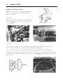
The
912
E
motor
is
fitted
with
a battery ignition system.
Due
to
the installation
of
the secondary air injection pump, the observation hole
for
the
timing
marker
is
no longer accessible. The TDC marker (previously on the fan wheel)
is
now located on the
fan-belt
pully
(arrow).
An
angle bracket which
is
secured
to
the air intake housing
serves
as
reference
point
.
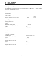
Technical Specifications: Ignition System
Firing order:
1-4-3-2
Dwell angle :
Timing:
27° before TDC at 3500 rpm
vacuum
hose
disconnected
Spark plugs:
Bosch W
175 M 30 plug
gap
0.7 mm
Beru
175114/3 L
T
he
distrib
utor
is
fitted
with
a vacuum operated advance and retard mechanism . The vacuum hose
fo
r retarding
is
green.
18

i
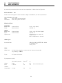
TECHNICAL
SPECIFICATIONS
Engine
Number
of
cylinders
Bore
Stroke
capacity (actual)
Compression ratio
Maximum
horse power rating
according
to
DI
N 70020
Net power SAE J 245
developed at :
Max
imum
torqu
e
acc
ording
to
01
N 70020
Ne
tt
torque SAE J 245
developed at :
Max
imum
rpm
Turn
off
revolutions
of
rpm li
miter
in
th
e c
ontrol
unit
Valve clearance: (engine cold)
Intake
Exhaust
En
gine weight kg/lbs
Emi
ss
ion system
F
ue
l supply
sys
tem
F
ue
l supp
ly
F
ue
l octane count requirements
El
ec
trical equipme
nt
Battery
Ba
tt
e
ry
option
al
Al
te
rnator
4
mm/in
.
94/3.70
mm/in
.
71/2.80
cm
3
/cu.in
19711120.3
7.6 : 1
HP/kW
90/66
HP/kW
86/64
rpm
4900
Kpm/Nm
141137
Ibft/Nm
98/133
rpm
4000
rpm
5500
rpm
5800 ± 100
0.
15
mm
0.20
mm
155/342
S
ec
ondary air inje
cti
o
n,
thermal reactor
and
ex
haust
gas
recirculation (EGR)
El
e
ctr
on i
ca
lly
con
troll
ed f
ue
l inj
ec
ti
on
-AFC
.
Electric pu'
mp
ROZ
91
12
V/44
A/hr.
12
V/66
A/hr
.
980
W,
70
14
V (B
osc
h)
19

TRANSMISSION
The 5
speed
transmission
923/02
is
a development
of
the transmission
type
915/44
(5
speed
trans-
mission
for
the 911) and
differs
from
it
in the
following
points :
1.
Clutch and operation
2.
Main shaft
sp
lines
3.
Ring gear and
pinion
ratio
4.
4th.
and
5th
. gear ratio
20

30
CLUTCH/CLUTCH
OPERATION
Clutch
pressure plate and disk.
The clutch
is
a single
dry
plate
clutch
of
pressed
design.
The
clutch
disk
has
24
splines,
unlik
e the 911
which
has
(SAE arrangement)
20
splin
es.
De
scr
iption
of
the pressure plate:
M
215
K Sph
D
escr
iption
of
the
clutch
disk:
215GUD
Plate pressure :
4903
- 5492 N (500 - 560 kp)
21

30
CLUTCH/CLUTCH
OPERATION
Clutch lever and cable
In order
to
obtai n a reverse movement
from
the one on the 911 model, the lever
was
moved in the
direction
of the transmission housing.
The
clut
ch cable
is
2080 ± 1.5 mm long and
has
a diameter
of
3.0 mm. The cable housing
is
secured
to one
of
the mou
nt
s on the transmission housing.
The distance of travel
for
the
lever (di
m.
A)
is
18.0 ± 1.5 mm.
Clut
ch
pe
da
l free movement
is
15 ± 5
mm
.
22

30
CLUTCH/CLUTCH
OPERATION
Adjustment
of
the lever and
fork
The lever and the
fork
must
be
correctly
located in order
to
assure
correct operation .
The dimensions are
as
follows
:
From t
he
mating surface on the transmission housing
to
the lever
is
71
mm.
;
Wit
h
out
a
lt
ering the
71
mm dimension, m
eas
ure the distance from the transmission housing
(i
n t
he
area
of
the
cl
ut
ch
cab
le
mounting
to
th
e
se
mi-circular depressi
on
for
the lever.
This dimension must
be
101
mm.
If
necessary, move the lever on
it
s
sp
lin
es.
23

30
Cl.UTCH/CLUTCH
OPERATION
Throw
out
bearing and guide
Throw
out
bearing :
The bearing
is
maintenance free and must
not
be
dismantled.
The guide
sleeve
for
the
throw
out
bearing
is
bolted
to
the transmission housing.
The main shaft oil
seal
is
held
within
the guide
sleeve
(for
ease
of
replacement
of
sea
l)
.
The
space
between transmission housing and guide
sleeve
is
sealed
by
an
O-ring.
24

34
35
SHIFT
MECHANISM/HOUSING
Transmission Mounts
Attached
to
the transmission
mount
is
a dampening material
to
reduce engine and transmission
vibrations and noise.
SHAFTS/GEARS
Main Shaft
The main shaft
is
also
provided
with
24 splines.
Gear-pair for 4th
and
5th
gear
As
previously mentioned, the transmission ratio
for
the 4th
and
5th
gear
in the transmission
unit
923/02
is
different
from that
in
the
915/44
transmission unit.
T
he
ratio differences
for
the
two
transmission units
are
as
follows :
Type
923/02
915/44
1
st
gear
11/35
i = 3.1818
11/35
2nd
gear
18/33
i = 1.8333
18/33
3rd
gear
23/29
i = 1.2609
23/29
4th
gear
26/25
i = 0.9615
26/26
i = 1.000
5th
gea
r
29/21
i = 0.7241
28/23
i = 0.8214
25

35
SHAFTS/GEARS
Ring
gear
and
pinion
The ratio
of
ring gear and pinion
is
also
different
in the
923/02
.
923/02
K : T 7 :
31
i = 4.4285
915/44
K : T
8 :
31
i = 3.
8750
Speedometer
Drive
The Type
912
E vehicles
are
equipped
with
an
electronically controlled speedometer.
Impulses
from
a magnetic disk which
is
mounted on the differential housing activate a
reed
relay.
From there the impulses
are
fed
to
the speedometer.
26

lJ
D
SPECIFICATIONS
Transmission (5
speed
transmission)
Vehicle type
Clutch
Pressure
plate
Pressure
N (kp)
Clutch disk
5
speed
manual transmission
Transmission Type
Ratio: 1st
gear
2nd
gear
3rd
gear
4th
gear
5th gear
Reverse
gear
Final drive
Final drive ratio
K/T
Limited slip differential
Slipping factor 40 %
Oi
I quantities:
Transmission
with
differential
Transmission oils
Transmission
number
-
Range
-
Model
year
1976
Sample serial No.
(7 digits)
Type
of
aggregate
Transmission
type
5
o
5 =
for
a 4 cyl .
motor
0=
5
gears
923
27
912
E
Single
dry
disk clutch
M
215
K Sph
4903
- 5492 (500 - 560)
215
Porsche - synchro-Iock transmission
923/02
11/35
i=3.1818
18/33
i = 1.8333
23/29
i = 1.2609
26/25
i = 0.
9615
29/21 i = 0.7241
12/21-20/38
i = 3.3250
Spiral conical
gear
Differential (Oerl ikon-gearing)
7/31 i = 4.4285
ZF
3.
0Itr
.
EP
oil,
Mil
2105 B standard, SAE
90
5 0 6 0001
Model year
Serial No.
6 0001
6 = 1976 0001
to
8000

SUSPENSION/BRAKES
The suspension
and
brake system in the
912
E
is
the
same
as
in the 911 models except
for
a
few
minor
details.
Front
axle independently suspended wheels on A-arms and struts, one torsion bar
for
each
wheel. Rack and pinion steering
with
safety column .
Safety steering wheel
with
padd :
ng,
stabilizer bar 16 mm dia.
Rear axle
independently suspended wheels on A-arms, torsion bar suspension
for
each
wheel .
WheelslTyres
Steel rims
5112
J x 15
fitted
with
165 HR 15 tyres.
Brakes
hydraulic, dual-circuit disk brakes,
with
solid disks.
28

40
FRONT
SUSPENSION
42
REAR
SUSPENSION
Vehicle alignment
specifications
The following specifications
are
valid
for
empty weight according
to
DIN 70020 (i.
e.
Vehicle including
full fuel tank,
spare
wheel
and
tool kit).
Front axle
Hight alignment :
Center
of
wheel
to
center line
of
torsion bar
99
mm
± 5
mm
3.90
in
Maximum difference from left
to
right
5mm
0.2 in
Total to-in
(pressed
15 kp)
Difference angle at a 20°
turning angle
0°
to
30'
Camber
(with
wheels straight
ahead)
0° 30' ± 10'
Maximum camber difference from left
to
right
10'
Caster
6° 5' ± 15'
Rear
axle
Hight
al
ignment :
From center
of
torsion bar
to
center
of
wheel
37 mm
± 5
mm/l.45
in
Maximum difference from left
to
right
8mm
To-in per wheel
20'
-
20'
Maximum difference from left
to
right
10'
Camber
0°
± 10'
Maximum difference from left
to
right
20'
29

40
FRONT
SUSPENSION
42
REAR
SUSPENSION
As previously mentioned, the
front
and rear suspension
is
identical
to
the Type 911 .
Shock
absorbers
-
rear
Either one
of
two
types
of
shock absorbers, 80ge
or
Woodhead ,
are
used
in production.
Shock absorber color code :
80ge black,
with
yellow
test band
Woodhead blue,
with
yellow
test band
Wheels
and
Tyres
Production
Wheel rims
front
and rear
5
1/2
J x 15 (steel)
Tyres
front
and rear
165
HR
15
Option
Wheel rims
front
and rear
5
1/2
J x 14
(LM
rims forged)
Tyres
front
and rear
185 HR 14
Spare wheel Inflatable
tyre
on a steel rim
5
1/2
J x 15,
with
a compressor or air tank
Winter
Tyres
Front
and rear
165
SR
15
MS
or
185170
SR
15
MS
on standard rims
5
1/2
J x 15
Note:
Wheel rims :
All
rims
have
a horn c
ontour
on the inner and outer side
(e.
g.
51/2J
x 15 H2)
Tyres:
All
tyres
are
tub
eless
Tyr
e pr
ess
ur
es
(cold) :
barometric pressure
(kp/cm
2
)
PSI
Front
2 bar
2
29
Also
for
wint
er tyres
Rear
2.35 bar
2.4
34
Reserve
(maximum)
2.0 bar 2.0 29
30

46
BRAKES
Hydraulic system/Brake failure warning device/
Hand brake warning light
As in the 911, the master brake cyl inder
is
fitted
with
a brake fai lure warn ing device . In the event
of
failure in one
of
the brake circuits a warning lamp
"BRAKE"
is
illuminated on the dash-board.
The
"BRAKE"
warning light also
serves
as
a hand brake warning light.
The hand brake warning lamp which
was
previously located in the combination instrument
is
no
longer
used.
31

46
BRAKES
Brake
disks
and
calipers
The
912
E
is
fitted
with
brake disks
without
ventilation on both
front
and rear axles.
(Refer
to
technical specifications
for
dimensions and
minimum
brake
pad
thicknesses).
Commencing
with
Mod. 76, a
type
brake caliper
is
installed on the
front
axle on all vehicles
including
911
's
o
Brake pads
Front
Rear
Jurid
231
GH
Textar TP
22
HH
Pad
thickness
10
mm
lOmm
32

TECHNICAL
SPECIFICATIONS
Front
suspension
-
steering
Wheel suspension
Torsion bar diameter
Stab
iIizer d
ia.
Shock absorber
Manufacturer
Steering
gear
Steering wheel dia.:
Standard
Optional
Steering ratio in the center (steering wheel
angle
to
wheel angle)
Turning circle dia.
Steering wheel turns
from
stop
to
stop
Steering
friction
(measured on steering flange
with
tie rods disconnected)
Rear
suspension
Wheel
suspension
Torsi
on
bar diameter
Stabi
Iizer
Shock absorbers
Manufacturer
Woodhead
Boge
Spring plate adjustment (inclination)
for
standard models
and
for
models
with
air conditioning
Independently suspended wheels on A-arms
and struts, one torsion bar
for
each
wheel .
18.8
mm/0.74
in.
16
mm/0
.
63
in.
Double acting hydraulic shock absorber
Boge/color coded : black
with
yellow
test band
ZF rack and pinion
400 mm115.75 in.
380
mm114.96 in .
17.78 : 1
10.9
mtr.l36
.76
ft.
3.1
0.8
to
1.4 Nm
(8
to
14 kpcm)
Independently suspended wheels on A-arms, one
torsion bar
for
each
wheel
23
mm/0
.9 in.
Double acting hydraulic shock absorbers
Either
Boge
or
Woodhead
Blue
with
yellow
test band
Black
with
yellow
test band
1°
spring plate inclination = approx. 8
to
9 mm (0.3
to
0.
35
in.) change in
hight
of
vehicle.
33

BRAKE
SYSTEM
TECHNICAL
SPECIFICATIONS
Foot brake
Tandem
master
cylinder
Bore diameter
Stroke
·Ratio at footbrake peddal
Free
travel : movement-rod/piston
Front
wheel
brakes
Brake disk O-dia.
Thickness
new
Minimum thickness after machini
ng
*)
Bra
ke
caliper piston d
ia.
Pad
thickness
Wear
limit
C
lea
rance
Pad
surface
area
for
each
wheel
Rear
wheel
brakes
Br
ake
disk O-dia.
Thickness new
Minimum thickness after
ma
chining
*)
We
ar
limit
Cleara
nce
Pad
su
rface
area
for
each
wheel
Hand
brake
Hand brake drum dia.
Wear
lim
it
dia.
Brake
shoe
width
Effective brake
area
per wheel
Wear
limit
for brake lining
Hydraulic, dual circuit disk brakes
with
brake
failure warn ing light
19
.05
mm/0
.75 in.
18113
mm/0
.
7110.51
in
.
5.4 : 1
1
mm/0
.39 in.
Solid disk - 282
mm111
.10 in.
12
.7 mm/0.5 in .
11
.5 mm/0.45 in.
48 mml1.89 in.
10
mm/0.39 in.
2.0 mm/0.079
in.
0.2 mm/0.0079 in.
76
cm
2
111
.78
sq
. in.
Solid disk - 290 mml11.4 in .
10.5 mm/0.41
in
.
9.5
mm/0
.374 in.
9.0
mm/0
.354
0.2 mm/0.0079
in.
52.5
cm
2
/8
.1375
Mechan i
cal
on both
rear
wheels
180
mml7
.086 in.
181
mml7
.126
in
.
25
mm/0
.98 in.
85cm
2
113.175sq. in.
2.0
mm/0
.079
in
.
*)
The brake disk must
be
symmetrically machined, the
same
amount on both
sides
of
the disk.
34

TECHNICAL
SPECIFICATIONS
Over-all dimensions
Length
mm/in.
4291/168.
94
Width
mm/in.
16101
63.39
Hight
mm/in.
13401
52 .76
Wheel
base
mm/in.
2271/ 89.41
Track
width
:
front
mm/in.
13601
53.54
Track
width
:
rear
mmlin.
13301 52.36
Road
clearance
mm/in.
1801
7.10
Weight
(DIN
70020)
kg
Ibs.
Empty
weight
1160
2258
Total weight
1400
3087
Axle
load
front
600
1323
rear
815
1797
Maximum load capacity
240
529
Maximum
roof
load
35
77
including
luggage
carrier
(Coupe only)
Fuel and Lubricants
Engine
The correct oil
level
Types
of
oil according
is
determined
by
the
to
A IP classification
dip-stick
as
described
in
SD
for
example:
the operating instructions
Summer SAE
30
Winter SAE 20
for
continuous temperatures
from - 15°C
to
O°C,
e.
g. 20 W 20. SAE 10 W
for
continuous temperatures
under
-15°C
.
Oil capacity
with
filter
change
3.5 Itr. approx.
Transmission incl. differential
3.0 Itr. transmission oil
according
to
MIL-L
2105
B,
SAE 90
35

TECHNICAL
SPECIFICATIONS
Fuel tank capacity
80 Itr. inc!. 8 Itr.
reserve
Brake fluid reservoir
0.2
Itr
. approx.
Windshield washer tank
8.0
Itr
. approx.
Performances
Top
speed
km/h
(mph)
178 (110.6)
Acceleration 0 - 100
km/h
s
13
.5
km
for
standing start
s
34.0 0 IN
empty
weight plus 1/2 load
Hill
climbing
ability
5
speed
transmission
1
st
gear
2nd
gear
3rd
gear
4th
gear
5th
gear
50%
27
%
17
%
11
%
7%
Chassis
number
range
Model
76
Sample serial number
(10digit)
912
Vehicle
type
6
Model year
6 = 1976
o
Motor
0=
912 E/2
Itr
.
o
Body
0=
0001
Serial No.
0001 - 9999
36

BODY/FITTINGS
The
body
on the
912
E
is
ide
nt
ica
l
to
that
of the 911 Model
s.
The
fol
lowi
ng
are
new on the 912 E
• Model
id
ent
ific
a
tio
n on r
ear
lid
• R
ear-
si
de
windows permanent installed
•
Ny
lon velour carpet
•
Seats
: Center
st
ripe in Scotch plaid, Tweed
or
braided material
37

BODY
/FITTINGS
The differentiating mark
is
the number identification
on
the rear lid .
The rear-side windows
are
permanently installed. The former
side
windows
are
available
as
an
option.
The single-stage heated rear-window
is
standardiequipment.
T
he
912 E interior upholstery consists
of
a nylon velour carpet, synthetic
seat
upholstery.
center stripe
of
Scotch plaid, Tweed or braided materials.
38

BODY/FITTINGS
As for the Type
911
Model 76, a radio
with
two
speakers, one in the right
and
one in the left door,
can
be
installed.
The speakerperforation on the
dash
board
was
removed.
Door locking push
button
The safety push
button
for
locking the
door
has
been
changed
from
8 mm
to
6.5 mm thickness.
This ensures
easier
opening
with
the key during variations in temperature.
39

BODY
/FITTINGS
Rear
cross-member
-
Engine
compartment
Various
fittings
and attachments are mounted on the rear cross-member :
for
air
filter
with
intake-air sensor
2
for
active carbon contai ner
3
for
the deceleration valve
4
for
the heating blower
motor
Motor
mountlR
ight-hand wheel well
The
motor
mount
-
left
and
right -
is
welded
to
the main
body
members (arrow)
Located in the right-hand wheel well
is
a compartment
for
the
AFC
control
unit
(5).
Also illustrated in the picture
is
one
of
the dampers
for
the safety bumpers
40

87
87
AIR
CONDITIONING
UNIT
Air conditioning unit
The air conditioning
unit
fitted
in the vehicle type
912
E
is
equipped
only
with
one condenser
which
is
secured to the engine lid.
Located on the receiver
dryer
is
a thermo switch (electrical switch) which disconnects the compressor
clutch
and
the air conditioning
unit
when the freon temperature
is
too
high.
When
the temperature
of
the freon drops the compressor clutch
and
the air conditioning
unit
are
turned on again.
41

~e
h
an
~e
gnit
i
on
-'-
p
_o
_in
_t_s
ired
I.
Required Maintenance for the Emissi
on
Control System 912 E
Required
Re
quired
Required
at 1,000 miles
every 5,000 miles
eve
ry
1
5,
000 miles
Change
Engine oil
Re
place
Engine oil filter
Replace
Replace
Valve clearance (at 5,000 miles, recommended for
Check
+ adjust
Check
+ adjust
maxi
mu
m e
ng
ine life, but not necessary to keep the
Check
+ adjust
(at 5,000 miles
on
ly)
Emission Con
tr
ol Warr
an
ty
in effect)
V-be
lt
s (including V-belt
for
air pump) check tension
Adjust
or
repla
ce
Adj
ust
and condition
if necessa
ry
Spark plugs Replace
Ignition distribut
or:
. _
Replace
Adjust
with electronic
dwell angle and timing
equipment
Check visually,
Ignition wiring,
distributor
cap and
rotor
replace
if
ne
cessary
Fuel filter Replace
EGR
syst
em
(reset
EGR
mileage counter) Check Visually *)
E
GR
system filter (reset
EGR
mileage counter)
Replace
*)
Evaporative control system (inc
l.
fuel cap, tank and
Check Visually
Check
Vi
su
ally
connections)
Crankcase ventilation hoses (control valv
e:
Check) Check visually
*)
Ex
haust s
yst
em Check for dam
ag
e
Check
+ adjust
Engine idle and exhaust emission (
CO)
Check
+ adjust
Air cleaner filter element (at least after
tw
o y
ea
rs)
Re
place
Air
pump, control valves, air injection hoses and
Check
connections
Filter element
for
ai
r pump Replace
Regular maintenance
of
the Emission Control System at 15,000 mile intervals is necessary to keep
yo
ur
Emission Control System War-
ranty valid.
*)
Additional service every
30,
000 miles.
II.
Ma
intenance and L
ub
rication Se
rv
ice
91
2 E
ReqUired at 1
,0
00 miles Req
Ui
re
d every 15,000 miles
Door
hinges
Lubricate
Door weatherstrips: Remove rubber residue from contacting areas
Maintain
and coat
with
talcum powder
or
other
su
itable rubber lubricant
Check and co
rr
ect
Change
Transmission oil
Change every 30,000 miles
Windshield washer, operation and fluid level
Check and corre
ct
Check
+ adj
ust
Front wheel bearing play
Front axle: Steering gear, tie-rod connections and rubber boots Check f
or
tightness
an
d leaks
Check
+ adju
st
Clutch pedal free play
Adjust
Br
ake system, all lines and hoses (incl. wear and leaks)
Check
Check Operation
of
lights, horn,
wip
ers and wash
er
Check
Check
Headlight adjustment Check and
corr
ect
Ignition / s
teer
ing lock
an
d buzz
er
alarm Check
Sa
fety
belt warning light and buzzer alarm
Check
Batte
ry
elec
tro
lyte level
Check
+ corr
ect
pres
su
re
Tires
Check and
cor
rect pressure
During road
or
dynamometer test
Check Braking, clutch,
st
eering, heating, ventilation systems
Check
Check
All
instruments, control and warning lights
Check
The recommended service intervals apply under normal driving conditions.
If
you drive mainly in
dusty
areas, check the air cleaner ele-
ment more often and replace
if
necessary. The condition
of
oil, and wear-and-tear items (such as tires, brakes, clutch lining) depend
greatly
on the amount
of
driving and on driving habits. Therefore, oil and wear-and-tear items should be checked more
fr
equently, and
if
necessa
ry
replaced
at
shorter intervals. Also, the battery electrolyte level should be checked more often. A complete
ma
intenance
and lubrication service should be performed at least once a year, preferably before the winter. The same applies
to
protective under-
coating
for
the vehicle.
42

Dr
. Ing. h. c.
F.
Porsche
Aktiengesellschaft
7000
Stuttgart
40
Postfach
400
640
Customer Service
Edited
by
Service School
Walter Muschweck
Werner Hahn
Hans Obinger
Dieter
Pr
inted
by
: Beck & Co.,
Stuttgart
40
Illustrations, descriptions and drawings are provided solely
to
clarify
the
text.
We
accept no responsibility
for
completeness
or
comformity
of
the
content
with
provisions valid
in
any
particular
case
. Subject
to
modification
without
notice.
1st
edition,
Sept.
1975


-
 1
1
-
 2
2
-
 3
3
-
 4
4
-
 5
5
-
 6
6
-
 7
7
-
 8
8
-
 9
9
-
 10
10
-
 11
11
-
 12
12
-
 13
13
-
 14
14
-
 15
15
-
 16
16
-
 17
17
-
 18
18
-
 19
19
-
 20
20
-
 21
21
-
 22
22
-
 23
23
-
 24
24
-
 25
25
-
 26
26
-
 27
27
-
 28
28
-
 29
29
-
 30
30
-
 31
31
-
 32
32
-
 33
33
-
 34
34
-
 35
35
-
 36
36
-
 37
37
-
 38
38
-
 39
39
-
 40
40
-
 41
41
-
 42
42
-
 43
43
-
 44
44
-
 45
45
-
 46
46
-
 47
47


En otros idiomas
- English: Porsche 912E 76
Otros documentos
-
Craftsman Brake Bleeder Vacuum Test Kit perform one person Brake bleeding; Automotive; Motorcycle ; ATV many other uses El manual del propietario
-
Land Rover L322 Range Rover Workshop Manual
-
Harbor Freight Tools Mityvac Vacuum Pump El manual del propietario
-
Innova 3145 El manual del propietario
-
Bosch OBD1000 Manual de usuario
-
Volkswagen Golf Plus 2005 Manual de usuario
-
-
Yamaha FX140 WaveRunner 2003 Manual de usuario
-
Ferrari 612 Scaglietti El manual del propietario
-