ROBLIN EPSILONE 400 VERRE BL El manual del propietario
- Categoría
- Campanas de cocina
- Tipo
- El manual del propietario

EPSILONE

2
2
SOMMAIRE
CONSIGNES DE SÉCURITÉ. ................................................................................................................................................ 3
CARACTERISTIQUES ........................................................................................................................................................... 6
INSTALLATION ...................................................................................................................................................................... 8
UTILISATION ....................................................................................................................................................................... 18
NETTOYAGE ET ENTRETIEN .............................................................................................................................................. 20
INDEX
SAFETY INFORMATION ....................................................................................................................................................... 23
CHARACTERISTICS ........................................................................................................................................................... 26
INSTALLATION .................................................................................................................................................................... 28
USE ...................................................................................................................................................................................... 38
CARE AND CLEANING ......................................................................................................................................................... 40
INHALTSVERZEICHNIS
SICHERHEITSINFORMATIONEN ......................................................................................................................................... 43
CHARAKTERISTIKEN ......................................................................................................................................................... 46
MONTAGE ........................................................................................................................................................................... 48
BEDIENUNG ........................................................................................................................................................................ 58
REINIGUNG UND WARTUNG ............................................................................................................................................... 60
INDICE
INFORMAZIONI SULLA SICUREZZA .................................................................................................................................... 63
CARATTERISTICHE ............................................................................................................................................................ 66
INSTALLAZIONE ................................................................................................................................................................. 68
USO ...................................................................................................................................................................................... 78
PULIZIA E MANUTENZIONE ................................................................................................................................................. 80
INDICE
INFORMACIÓN DE SEGURIDAD .......................................................................................................................................... 83
CARACTERÍSTICAS ........................................................................................................................................................... 86
INSTALACIÓN ..................................................................................................................................................................... 88
USO ...................................................................................................................................................................................... 98
LIMPIEZA Y MANTENIMIENTO ........................................................................................................................................... 100
INHOUDSOPGAVE
VEILIGHEIDSINFORMATIE ................................................................................................................................................. 103
EIGENSCHAPPEN ............................................................................................................................................................ 106
INSTALLATIE ..................................................................................................................................................................... 108
GEBRUIK ........................................................................................................................................................................... 118
REINIGING EN ONDERHOUD ............................................................................................................................................ 120
FR
EN
DE
IT
ES
NL

FR
3
3
CONSIGNES DE SÉCURITÉ
Pour votre sécurité et pour garantir le fonctionnement correct de
l’appareil, veuillez lire attentivement ce manuel avant d’installer et de
mettre en fonction l’appareil. Toujours conserver ces instructions avec
l’appareil, même en cas de cession ou de transfert à une autre personne.
Il est important que les utilisateurs connaissent toutes les caractéristiques
de fonctionnement et de sécurité de l’appareil.
La connexion des câbles doit être effectuée par un technicien compétent.
En aucun cas le fabricant ne peut être tenu pour responsable d’év
entuels
dommages dus à une installation ou à une utilis
ation impropre.
La distance de sécurité minimum entre le plan de cuiss
on et la hotte
aspirante est de 650 mm (c
ertains modè
les peuvent être installés à une
hauteur inf
érieure ; voir le paragraphe concernant les
dimensions de travail
et l’installation).
Si les instructions d’installation du plan de cuisson à gaz spécifient une
distance supérieure à celle indiquée ci-dessus, veuillez impérativem
e
nt en
tenir compte.
Assurez
-vous que la tension du secteur corres
pond à celle indiquée sur la
plaque des caractéristiques apposée à l’intérieur de la hotte.
Les dispositifs
de sectionnement doivent être mont
és dans l’installation fixe
conformément aux normes sur les systèmes de câblage.
Pour les appareils de Classe I, s’assurer que l’installat
i
on électrique de
votre int
érieur dispose d’une mise à la terre adéquate.
Reliez l’aspirateur du conduit de chemin
ée avec un tube ayant un diamètre
minimum de 120 mm. Le parcours des f
umées doit êt
re le plus court
possible.
Respecter toutes les norm
es concernant l’évacuation de l’air.
Ne reliez pas la hotte aspirante aux conduits de chem
inée qui acheminent
les fumées de combustion (par ex. de c
haudières, de cheminées, et
c.).

FR
4
4
Si vous utilisez l’aspirateur en même temps que des appareils non électriques
(par ex. fonctionnant au gaz), veillez à ce que la pièce soit adéquatement
ventilée, afin d’empêcher
le retour du flux des gaz d’évacuation. Si vous utilise
z
la hotte de cuisine en même temps que des appareils non alimentés à
l’électricité, la pression négative dans la pièce ne doit pas dépasser
0,04 mbar
,
afin d’éviter que les fumées soient réaspirées dans la pièce où se trouve la
hotte.
Ne pas évacuer l’air
à travers une conduite utilisée pour
l’évacuation des
fumées des appareils de combustion alimentés au gaz ou avec d’autres
combustibles.
Si le cordon d’alimentation est endommagé, faites-le remplacer par le fabricant
ou par
un technicien d’un service après-
vente agréé.
Branchez la fiche à une prise conforme aux normes en vigueur et dans une
position accessible.
En ce qui concerne les dimensions techniques et de sécurité à adopter pour
l’évacuation des fumées, veuillez vous confor
mer scrupuleusement aux
règlements établis par
les autorités locale
s.
AVERTISSEMENT : Avant d’installer la hotte, retirer les films de protection.
Utilisez exclusivement des vis et des petites fourniture
s du type adapté pour la
hotte.
AVERTISSEMENT toute installation de vis et de dispositifs de fixation non
conf
ormes à ces instructions peut entraîner des risques de déchar
ges
électriques.
Ne pas obser
ver directement avec des instruments optiques
(jumelles, lentilles
grossissantes...).
Ne flambez pas des mets sous la hotte : sous risque de développer un
incendie.
Cet appareil peut être utilis
é par des enfants de plus de 8 ans et par
des
personnes dont les capacités physiques, sensorielles ou mentales sont
diminuées ou ayant une expérience et des connaissances insuffisantes, pourvu
que ce soit sous la sur
veillance attentive d’une per
sonne responsable et après
avoir
reçu des instructions sur la manière d’utiliser cet appareil en toute sécuri
té
et sur
les dangers que cela comporte. Assurez-vous que les enfa
nts ne jouent
pas avec cet appareil. Le nettoyage et l’entretien de la part de l’utilisateur ne
doivent pas être effectués par des enfants, à moins qu’ils ne soient surveillés.
Surveillez les enfants. S’assurer qu’ils ne jouent pas avec l’appareil.

FR
5
5
Cet appareil n’est pas destiné à être utilisé par des personnes (enfants
compris
) dont les capacit
és physiques, sensorielles ou mentales sont
diminuées ou ayant une expérience et des connaissances insuffisantes, à
moins que celles-ci ne soient attentivem
ent surveillées et instruites.
Les parties accessibles peuvent devenir très chaudes durant l’utilisation
des appareils de cuisson.
Nettoyer et/ou remplacer les filtres après le délai
indiqué (danger
d’inc
endie). Voir le paragraphe Nettoyage et Entretien.
Veillez à ce que la pièce bénéficie d’une ventilation adéquate lors
que la
hotte fonctionne en mêm
e temps que des appareils uti
lisant du gaz ou
d’aut
res combustibles (non applicable au
x appareils qui évacuent l’air
uniquement dans la pièce).
Le symbole
marqué sur le produit ou sur son emballage indique que ce
produit ne peut pas être éliminé comme déchet ménager normal. Lorsque
ce produit doit
être éliminé, veuillez le remettre à un c
entre de collecte
prévu pour le recyclage du matériel électrique et électronique. En vous
assurant que cet appareil est éliminé correctement, vous partic
i
pez à
prévenir des conséquences potentiellement négatives pour l'environnement
et pour la santé, qui risqueraient de se présenter en cas d’élimination
inappropriée. Pour toute information supplémentaire sur le recyclage de ce
produit, contactez votre municipalit
é, votre déchetterie locale ou le m
agasin
où vous avez acheté ce produit.

FR
6
6
CARACTERISTIQUES
Composants
Réf. Q.té Composants du produit
1 1 Corps de hotte équipé de : commandes, lumière, filtres, moteur.
2 1 Plaque support hotte
3 4 Vitres
Réf. Q.té Composants de l’installation
11 4 Chevilles ø 10
12a 4 Vis 4,2 x 44,4
12b 8 Vis 4 x 8
12c 8 Écrous
12d 8 Rondelles D.4,3 x 10
Q.té Documentation
1 Manuel d’instructions

FR
7
7
Encombrement

FR
8
8
INSTALLATION
Cette hotte est prévue pour être installée au plafond/étagère, au-dessus (650 mm min.) d’un plan de
cuisson en îlot en :
• Version aspirante : évacuation à l’extérieur.
• Version fil
trante : recirculation intérieure.
Séquence des opérations d’installation
• Préparation à l’installation
• Perçage plafond/étagère et fixation plaque de support
• Connexions
•
Montage du corps de hotte
• Contrôle
fonction
nel
•
Élimination des emballages
Ouverture de la plaque et préparation à son montage
• Desserrer les vis qui unissent la plaque à son couvercle.
• Prendre la plaque et la placer dans le sens correct comme indiqué dans la figure. Le cliquet
doit se trouver en face de l’installateur.

FR
9
9
Perçage plafond/étagère et fixation plaque
PERÇAGE PLAFOND/ÉTAGÈRE
• À l’aide d’un fil à plomb, ramener sur le plafond/étagère de support le centre du plan de
cuisson.
• Appuyer la plaque au plafond/étagère en veillant de la positionner dans le bon sens, comme
indiqué dans la figure.
• Marquer les centres des trous de la plaque.
• Percer les points suivants :
• Plafond en béton massif : selon les chevilles pour béton employées.
• Plafond en béton et chambre à air, avec une épaisseur résistante de 20 mm : percer ø 10
mm (insérer tout de suite les chevilles 11 fournies).
• Plafond en poutres de bois : selon les vis pour bois employées (non fournies).
• Étagère en bois, avec une épaisseur résistante de 15 mm : percer ø 7 mm.
• Passage du câble électrique d’alimentation : percer ø 10 mm.
• Sortie air (version aspirante) : selon le diamètre de la liaison au tuyau de l’évacuation exté-
rieure.
• Serrer en diagonale et en laissant 4-5 mm du plafond les deux vis :
• pour béton massif, les chevilles pour béton, non fournies.
• pour béton avec chambre à air, avec une épaisseur résistante d’environ 20 mm, vis 12a
fournies.
• pour poutres de bois, vis pour bois, non fournies.
• pour étagère de bois, vis avec rondelles et écrous non fournies.

FR
1
10
FIXATION PLAQUE
• Soulever la plaque de fixation, emboîter les trous sur
les deux vis précédemment prévues au plafond et
tourner jusqu’au centre du trou de réglage.
Attention : le sens de la plaque doit être celui indiqué
dans la figure.
• Serrer les deux vis et visser les deux autres fournies ;
avant de serrer définitivement les vis, vous pouvez
effectuer des réglages en tournant la pièce, en faisant
attention à ce que les vis ne sortent pas du siège du
trou de réglage.
• La fixation doit être sûre aussi bien par rapport au
poids de la hotte qu’aux contraintes provoquées par
des poussées latérales occasionnelles lorsque
l’appareil est monté. À la fin de la fixation, vérifier
que la plaque est stable.
• Au cas où le plafond ne serait pas suffisamment
robuste dans le point de suspension, l’installateur
devra le renforcer à l’aide de plaques et de contre-
plaques opportunes ancrées aux parties
structurellement résistantes.
• Vérifier le nivellement de la plaque au plafond.
2
1
2
1

FR
1
11
a
b
c
CONNEXION CÂBLES HOTTE-PLAQUE
N.B. Avant de commencer l’installation, il est nécessaire d’amener la hotte à une hauteur d'au moins 650
mm du plan de cuisson, avec un support ou en se faisant aider par une autre personne. Prendre
garde de ne pas dépasser la cote maximum d’extension de la hotte indiquée dans le croquis coté.
Cette mesure est fondamentale, puisque les câbles de la hotte devant être branchés à la plaque
montée au plafond, il est impératif d’éviter que le poids de la hotte puisse peser sur la structure.
Le système de fixation des 4 câbles est formé de 3 parties :
• Cliquet fileté (a) déjà monté sur la plaque de plafond.
• Vis serre-câble (b) fournie.
• Pommeau de sécurité (c) fourni.
• Passer les 4 câbles (accrochés au corps de
hotte) dans les trous correspondants du
couvercle de la hotte, précédemment
déposé, en veillant à ce que le sens soit le
même que celui de la plaque accrochée au
plafond.
• Insérer le câble d’alimentation de la hotte dans le
trou prévu sur le couvercle.
Attention : ne pas casser ni retirer le collier
qui fixe le câble d’alimentation de la hotte.

FR
1
12
• Faire attention au sens d’orientation de la
plaque fixée au plafond (le cliquet de fin de
course de la plaque présente son trou cor-
respondant sur le couvercle de la plaque et
sur le corps de hotte).
• Enfiler les pommeaux de sécurité (c)
dans leurs câbles correspondants, en
veillant à ce que le filetage soit orienté
vers le haut.
• Enfiler les vis serre-câble (b) dans leurs
câbles respectifs.
b
c

FR
1
13
• Faire passer les câbles dans les trous des cliquets filetés (a)
et serrer les vis serre-câble (b) à ces mêmes cliquets.
• À la fin de l’opération, le résultat
doit être celui représenté dans la
figure pour tous les 4 câbles.
• À ce point, les 4 câbles sont reliés à la
plaque.
Mettre les câbles sous tension en les
poussant vers le haut de manière à ce
qu’ils coulissent dans la vis serre-câble
et hors du trou du cliquet fileté.
Cela est possible, car le système présent
dans la vis serre-câble permet au câble
de coulisser dans un seul sens à son
intérieur, en bloquant le coulissement
dans l’autre sens.
Veiller à ce que les câbles aient tous la
même longueur pour faciliter
l’opération de nivellement final. Faire
attention à ce que le câble avant gauche
ne soit pas plus mou que les autres.

FR
1
14
NIVELLEMENT DE LA HOTTE
• Il est nécessaire d’effectuer le nivellement du
corps de hotte.
• Le nivellement de la hotte s’effectue en
intervenant sur les cliquets de sécurité C.
• Appuyer un niveau sur la hotte.
• Pour « débloquer » le mouvement du câble,
exercer une pression vers le haut, sur les
pommeaux de sécurité. Insérer ou extraire le câble
de la vis serre-câble pour effectuer les réglages qui
permettent de niveler le corps mobile de la hotte.
• Après avoir nivelé la hotte selon nécessité, serrer
les pommeaux de sécurité.
Attention :
• Vérifier que tous les 4 câbles de soutien sont tendus.
• Vérifier que tous les 4 câbles de soutien n’ont subi aucun dommage durant
l’installation.
• N’oubliez pas que la distance minimum entre la hotte et le plan de cuisson de la cuisine
doit être de 650 mm. Prendre garde de ne pas dépasser la cote maximum d’extension
de la hotte indiquée dans le croquis coté.

FR
1
15
Connexions
SORTIE AIR VERSION ASPIRANTE
Pour l’installation de la hotte version aspirante, voir les instruc-
tions contenues dans le kit d’aspiration spécifique pour la hotte.
SORTIE DE L’AIR VERSION FILTRANTE
• Ouvrir le groupe d’éclairage en le tirant sur l’encoche prévue à
cet effet.
• Retirer le filtre à graisse.
• S’assurer de la présence des filtres anti-odeur à charbon actif.

FR
1
16
FIXATION DU CÂBLE D’ALIMENTATION
• Tendre le câble d’alimentation et le fixer à la bride sur la plaque de plafond, en utilisant la
languette déjà montée avec 2 vis.
• Emboîter le passe-câble en caoutchouc déjà enfilé
sur le câble d’alimentation dans le trou, pour
éviter tout endommagement futur.
• Brancher la hotte à
l’alimentation de secteur en in-
tercalant un interrupteur bipo-
laire ayant une ouverture des
contacts d’au moins 3 mm.
• Retirer les filtres à
graisse (voir par. « En-
tretien ») et s’assurer
que le connecteur du
câble d’alimentation est
correctement branché
dans la prise de
l’aspirateur.
• À ce point, vous pouvez
couper le collier qui
bloque le câble
d’alimentation au corps
de hotte.
MONTAGE DU COUVERCLE DE LA PLAQUE
• À l’aide des vis précédemment retirées, revisser le
couvercle à la plaque.

FR
1
17
FIXATION DES VITRES
• Accrocher les 4 vitres
au corps de hotte en
enfilant les ailettes
sur les trous prévus à
cet effet.
• Niveler les 4 vitres
manuellement en
effectuant de petits
réglages sur ces
mêmes vitres.
• En passant par la partie supérieure, fixer les 4 vitres avec
les vis 12b et les Rondelles 12d fournies, en vous assurant
de conserver le nivellement entre elles.
• En passant par la partie
inférieure, fixer définitivement
les 4 vitres avec les écrous 12c
fournis, en vous assurant de
conserver le nivellement entre
elles.
Attention
Vérifier que les vitres de la hotte sont parfaitement alignées et nivelées. Si cela n’est pas,
vous pouvez effectuer des réglages en desserrant les écrous 12c ou les vis 12b de manière
qu’en déplaçant les vitres, celles-ci s’alignent parfaitement.
12b
12d

FR
1
18
UTILISATION
Tableau des commandes
L T1
Touche Fonction Affichage
L Allume/Éteint les lumières -
T1 Hotte basse
Appuyer pendant 2 secondes pour remonter la
hotte.
Appui bref On/Off moteur
Branché/Débranché
Hotte haute
Premier appui : La hotte descend.
Deuxième appui : Stop hotte.
À la fin du mouvement, le moteur se branche à
la deuxième vitesse.
Débranché/Débranché
L’électronique reconnaît deux types d’anomalies et donne le signal correspondant
Led T1
Clignotement lent
Dépassement du seuil d’absorption de courant:
En présence d'une condition de surcharge, l'anomalie est signalée par le
clignotement, toutes les 2 secondes, de la led T1 située sur le clavier.
Vérifier l’absence de tout empêchement durant le mouvement de la hotte.
Ce signalement demeure actif jusqu’à ce qu’une nouvelle commande
d’ouverture/fermeture de la hotte soit donnée.
Clignotement rapide
Intervention du microswitch de sécurité en ouverture:
En cas d’intervention du microswitch de sécurité, l’anomalie est signalée
par le clignotement rapide de la led T1 (toutes les 250ms), indiquant que la
hotte a dépassé le fin de course…….. Contacter le service après vente!
En présence de cette anomalie, l’accès aux fonctions de la hotte (lumières et
moteur) est toujours possible. Si le moteur est branché, la led T1 continuera
à clignoter, signalant que l’anomalie est toujours présente.

FR
1
19
TÉLÉCOMMANDE
Cet appareil peut être commandé via une télécommande,
alimentée avec une batterie 3 V type CR2032 (non fournie).
• Ne pas ranger la commande à proximité de sources de
chaleur.
• Ne pas jeter les batteries dans la nature, mais les déposer
dans les bornes de collecte.
Branche/Débranche le moteur.
-
Hotte fermée :
- En appuyant brièvement sur la touche la hotte commence à descendre
- À la pression suivante, elle s’arrête.
Lorsque le mouvement est terminé, le moteur se branche à la 2
ème
vi-
tesse.
-
Hotte ouverte :
- Appuyer pendant 2 secondes pour activer le mouvement de remon-
tée qui s’arrête avec le fin de course.
- Appuyer (brièvement) pour arrêter le mouvement (avant le fin de
course).
- Appuyer encore brièvement, on/off moteur.
- Garder appuyé pendant 2 secondes pour activer le mouvement de re-
montée.
- Si le moteur est branché, d’abord le moteur s’arrête, puis le moteur
démarre.
-
-
-
Branche/Débranche les lumières de la hotte.
-
INTENSIVE
- Activable seulement lorsque la hotte est descendue et lorsque le delay
ou le 24h ne sont pas actifs.
- Active la vitesse intensive à partir de n’importe quelle vitesse.
Pour la débrancher, appuyer de nouveau sur cette même touche ou
éteindre le moteur.
- La vitesse intensive est temporisée à 6 minutes. À la fin des 6 mi-
nutes le système retourne automatiquement à la vitesse précédem-
ment programmée.
La led présente sur
la touche moteur
(des commandes
hotte) clignote 1
fois par seconde).
Appuyer brièvement sur la fonction Delay :
Activable seulement lorsque l’Intensive ou le 24h ne sont pas actifs.
Branche et débranche le mode d’arrêt total de la hotte (mo-
teur+lumières) après 30 minutes :
Pour invalider le Delay, appuyer de nouveau sur la même touche ou
éteindre le moteur.
La led p
r
ésente sur
la touche moteur
(des commandes
hotte) clignote
toutes les 0,5 se-
conde
)
.
Appuyer pendant 2 sec sur la fonction 24h :
Activable seulement lorsque l’Intensive ou le Delay ne sont pas actifs.
Branche et débranche la fonction 24 pendant 10 minutes par heure,
pendant 24 heures. À l’expiration, la fonction se désactive.
La led p
r
ésente sur
la touche moteur
(des commandes
hotte) clignote
toutes les 2 se-
condes
)
.
Augmente la vitesse du moteur.
-
Diminue la vitesse du moteur.
-

FR
2
20
NETTOYAGE ET ENTRETIEN
Filtre à graisse métallique
Il est lavable même au lave-vaisselle. Il doive être lavé environ
tous les 2 mois d’utilisation ou plus fréquemment en cas
d’utilisation particulièrement intensive.
NETTOYAGE FILTRE À GRAISSE MÉTALLIQUE
• Ouvrir le groupe d’éclairage en le tirant sur l’encoche prévue à
cet effet.
• Retirer le filtre, en le poussant vers l’arrière du groupe, tout en
tirant en même temps vers le bas.
• Laver le filtre en évitant de les plier et les laisser sécher avant
de les remonter.
• Le remonter en veillant à ce que la poignée soit toujours vers la
partie visible externe.
• Refermer le groupe d’éclairage.
Filtres anti-odeur à charbon actif (version filtrante)
Il n’est ni lavable ni régénérable, le remplacer après environ 4
mois d’utilisation ou plus fréquemment en cas d’utilisation parti-
culièrement intense.
REMPLACEMENT
• Ouvrir le groupe d’éclairage.
• Retirer le filtre à graisse.
• Enlever les filtres anti-odeur à charbon actif saturés, comme
indiqué (A).
• Monter les nouveaux filtres, comme indiqué (B).
• Remonter le filtre à graisse et le groupe d’éclairage.
A
B
Éclairage
• Pour le remplacement, contacter le Service après-vente (« Pour
l’achat, s’adresser au service après-vente »).

FR
2
21
Procédure d’intervention en cas d’anomalies sur le mouvement
• Vérifier que le fusible est correctement inséré et qu’il n’est pas brûlé. En cas de néces-
sité de remplacement, ouvrir le groupe d’éclairage et desserrer le porte-fusible visible
sur la gauche du groupe moteur, en le remplaçant par un autre fusible ayant les mêmes
caractéristiques (Réf. A).
• Vérifier que le corps de hotte est installé à niveau (l’utilisation d’un niveau est con-
seillée).
• Vérifier que les quatre câbles sont tendus tous les quatre de la même manière.
Si les actions précédentes n’ont pas résolu le problème, contacter le service après-vente.
A

FR
2
22
GARANTIE COMMERCIALE ET SERVICE APRES
GARANTIE COMMERCIALE
La garantie commerciale fournie par la société FRANKE FRANCE SAS pour les produits de
marque ROBLIN est limitée aux professionnels de la distribution. Elle est applicable à la France
continentale, à la Corse, et aux DOM-TOM.
La garantie commerciale est une garantie de de 2 ans pièces (hors frais de main d’œuvre et dépla-
cement). Elle s’applique à compter de la date de facturation de l'appareil au consommateur sous ré-
serve que celle-ci se situe dans les 12 mois suivants la date de vente par ROBLIN au Client.
Afin de satisfaire le consommateur lors de toute intervention de service après-vente, le Client
s’engage à l’orienter vers le service mis en place par ROBLIN afin d’organiser la prise en charge
dans les meilleurs délais. Le service après-vente est joignable au numéro suivant : 04 88 78 59 93.
Les éléments à communiquer au service après-vente ROBLIN sont :
Un descriptif de la panne constatée
La référence commerciale du produit ainsi que son numéro de série
La copie de facture d’achat du consommateur ainsi que ses coordonnées.
Cette garantie s’applique à tous problèmes techniques ou fonctionnels. Sont exclues de la garantie
commerciale :
- Les pannes concernant les accessoires ou les pièces consommables (filtres, ampoules …),
- Les dommages, pannes et défauts imputables à des causes d’origine extérieure,
- Les dommages dus à la corrosion, à un mauvais branchement ou alimentation,
- Les dommages dus au non-respect des instructions fournies par ROBLIN (installation, mon-
tage,…),
- Les pannes résultant de la modification de la construction et des caractéristiques de l’appareil de
marque ROBLIN,
- Les pannes et dommages survenant suite à l’utilisation de pièces détachées non conformes à
celles fournies d’origine par ROBLIN ou à un défaut d’entretien,
- Les pannes résultant d’un usage professionnel ou commercial des appareils.
DISPONIBILITE DES PIECES DETACHEES
En application de l’article R 111-3 du Code de la consommation, pour les produits mis sur le mar-
ché à compter du 1er mars 2015, ROBLIN garantit la disponibilité des pièces détachées indispen-
sables à l’utilisation de ses Produits pendant une durée de 10 ans à compter de l’achat du produit par
le consommateur, la facture faisant foi, sous réserve que celle-ci se situe dans les 12 mois suivants la
date de vente par ROBLIN au Client.

EN
2
23
SAFETY INFORMATION
For your safety and correct operation of the appliance, read this manual
carefully before installation and use. Always keep these instructions
with the appliance even if you move or sell it. Users must fully know the
operation and safety features of the appliance.
The wire connection has to be done by specialized technician.
The manufacturer will not be held liable for any damages resulting from
incorrect or improper installation.
The minimum safety distance between the cooker top and the extractor
hood is 650 mm (some models can be installed at a lower height,
please refer to the paragraphs on working dimensions and installation).
If the instructions for installation for the gas hob specify a greater
distance, this must be respected.
Check that the mains voltage corresponds to that indicated on the
rating plate fixed to the inside of the hood.
Means for disconnection must be incorporated in the fixed wiring in
accordance with the wiring rules.
For Class I appliances, check that the domestic power supply
guarantees adequate earthing.
Connect the extractor to the exhaust flue through a pipe of minimum
diameter 120 mm. The route of the flue must be as short as possible.
Regulations concerning the discharge of air have to be fulfilled.
Do not connect the extractor hood to exhaust ducts carrying
combustion fumes (boilers, fireplaces, etc.).

EN
2
24
If the extractor is used in conjunction with non-electrical appliances
(e.g. gas burning appliances), a sufficient degree of aeration must be
guaranteed in the room in order to prevent the backflow of exhaust gas.
When the cooker hood is used in conjunction with appliances supplied
with energy other than electric, the negative pressure in the room must
not exceed 0,04 mbar to prevent fumes being drawn back into the room
by the cooker hood.
The air must not be discharged into a flue that is used for exhausting
fumes from appliances burning gas or other fuels.
If the supply cord is damaged, it must be replaced from the
manufacturer or its service agent.
Connect the plug to a socket complying with current regulations,
located in an accessible place.
With regards to the technical and safety measures to be adopted for
fume discharging it is important to closely follow the regulations
provided by the local authorities.
WARNING: Before installing the Hood, remove the protective films.
Use only screws and small parts in support of the hood.
WARNING: Failure to install the screws or fixing device in accordance
with these instructions may result in electrical hazards.
Do not look directly at the light through optical devices (binoculars,
magnifying glasses…).
Do not flambè under the range hood; risk of fire.
This appliance can be used by children aged from 8 years and above
and persons with reduced physical, sensory or mental capabilities or
lack of experience and knowledge if they have been given supervision
or instruction concerning use of the appliance in a safe way and
understand the hazards involved. Children shall not play with the
appliance. Cleaning and user maintenance shall not be made by
children without supervision.
Children should be supervised to ensure that they do not play with the
appliance.

EN
2
25
The appliance is not to be used by persons (including children) with
reduced physical, sensory or mental capabilities, or lack of experience
and knowledge, unless they have been given supervision or instruction.
Accessible parts may become hot when used with cooking appliances.
Clean and/or replace the Filters after the specified time period (Fire
hazard). See paragraph Care and Cleaning.
There shall be adequate ventilation of the room when the range hood is
used at the same time as appliances burning gas or other fuels (not
applicable to appliances that only discharge the air back into the room).
The symbol
on the product or on its packaging indicates that this
product may not be treated as household waste. Instead it shall be
handed over to the applicable collection point for the recycling of
electrical and electronic equipment. By ensuring this product is
disposed of correctly, you will help prevent potential negative
consequences for the environment and human health, which could
otherwise be caused by inappropriate waste handling of this product.
For more detailed information about recycling of this product, please
contact your local city office, your household waste disposal service or
the shop where you purchased the product.

EN
2
26
CHARACTERISTICS
Components
Ref. Q.ty Product Components
1 1 Hood Canopy complete with: Controls, Light, Filters, Motor.
2 1 Hood support plate.
3 4 Glass elements
Ref. Q.ty Installation Components
11 4 Wall Plugs ø 10
12a 4 Screws 4.2 x 44.4
12b 8 Screws 4 x 8
12c 8 Nuts
12d 8 Washers D.4,3 x 10
Q.ty Documentation
1 Instruction Manual

EN
2
27
Dimensions

EN
2
28
INSTALLATION
This hood is designed to be mounted on the ceiling/on a shelf, above a free-standing Hob (min. 650
mm), in:
• Ducting version: Evacuation to the outside.
• Recirculation version: Internal recirculation.
Sequence of operations - Installation
• Preparing for installation
• Drilling the Ceiling/Shelf and Fixing the support plate
• Connections
• Fitting the Hood canopy
• Functional Check
• Disposal of Packaging
Opening the Plate and preparing for assembly
• Unfasten the screws joining the Plate to its Cover.
• Take the Plate and position it the right way round, as shown in the figure. The pawl must
face towards the installer.

EN
2
29
Ceiling/Shelf drilling and Plate Fixing
CEILING/SHELF DRILLING
• Use a plumb-line and mark the centre of the cooking hob on the Support Ceiling/Shelf
• Rest the Plate against the Ceiling/Shelf, making sure it is the right way up, as shown in the
figure.
• Mark the centres of the holes in the plate.
• Drill the following points:
• Ceilings in solid concrete: As per concrete plugs used.
• Ceilings in hollow bricks with 20 mm resistance thickness: Drill a hole ø 10 mm (insert
Plugs 11 supplied immediately).
• Ceilings with Wood Beams: As per Wood Screws used (not supplied).
• Wooden shelf, with a resistant thickness of 15 mm: drill a hole ø 7 mm.
• Feeding the electric supply cable: drill a hole ø 10 mm.
• Air Outlet (Ducting Version): according to the diameter of the connection to the external
ducting pipe.
• Insert two screws, crossing them and leaving 4-5 mm from the ceiling:
• for solid concrete, concrete plugs, not provided.
• for hollow bricks with approx. 20 mm resistance thickness, screws 12a, provided.
• for wooden beams, wood screws, not provided.
• for wooden shelves, screws with washers and nuts, not provided.

EN
3
30
FIXING THE PLATE
• Lift up the Fixing plate and fit the slots onto the two
screws previously inserted in the ceiling, and turn un-
til they are at the centre of the adjustment slot.
Warning: The plate must be facing in the direction
shown in the figure
• Tighten the two screws completely and screw in the
other two provided; before locking the screws
completely it is possible to make adjustments by
turning the piece, making sure that the screws do not
come out of the adjustment slot.
• The unit must be securely fastened both due to the
weight of the Hood and the stress caused by
occasional sideways pressure on the Appliance when
in position. Once the unit has been fixed, make sure
that the plate is stable.
• In all cases where the Ceiling is not sufficiently
strong at the point of suspension, the Installation
technician must strengthen it with suitable plates and
counterplates, anchored to structurally sound
elements.
• Check that the plate is level on the ceiling.
2
1
2
1

EN
3
31
CONNECTING HOOD-PLATE CABLES
N.B. Before proceeding with installation the Hood must be raised to a height of at least 650
mm above the cooker hob by means of a support or with the assistance of another
person. Be careful not to exceed the maximum Hood extension indicated in the
dimensional drawing.
This operation is essential, as the Hood Cables are to be connected to the Plate mounted
on the ceiling, and this must be done without the weight of the Hood bearing down on
the structure.
The system used to fix the 4 Cables comprises 3 components:
• Threaded pawl (a) already mounted on the ceiling Plate.
• Cable locking screw (b), provided.
• Safety knob (c), provided.
• Pass the 4 cables (connected to the
Hood Canopy) through the respective
holes in the Plate Cover after
dismantling as above, making sure that
they face the same way as the plate
connected to the ceiling.
• Insert the Hood power cable into the hole
provided in the Cover.
Warning: Do not break or remove the
clamp fixing the power cable to the Hood
a
b
c

EN
3
32
b
c
• Pay attention to the direction in which the Plate
is fixed to the ceiling (the Plate limit pawl has a
corresponding hole on the Plate cover and on
the Hood canopy).
• Insert the safety knobs (c) into the
respective cables, with the thread to the
top.
• Insert the cable locking screws (b) into
the respective cables.

EN
3
33
• Pass the Cables into the slots on the threaded pawls (a) and
tighten the cable locking screws (b) into the pawls
themselves.
• When the operation has been
completed, the result should be as
shown in the figure for all 4
cables.
• At this point, all 4 cables are now
connected to the Plate.
Tension the Cables by pushing them
upwards, so that they slide inside the
cable locking screw and out through the
slot in the threaded pawl.
This is possible because the cable
locking screw involves a system that
allows the Cable to slide in one direction
only, preventing it from sliding in the
other direction.
Make sure that the Cables are all the
same length, to facilitate final levelling
operations. The left front cable must not
be slacker than the others.

EN
3
34
LEVELLING THE HOOD
• The hood canopy must be levelled.
• The Hood is levelled by adjusting the safety pawls
C.
• Rest a spirit level on the hood.
• Exerting an upwards pressure on the safety knobs
“unlocks” movement of the Cable. By inserting or
extracting the cable from the cable locking screw
it is possible to make adjustments to level the
mobile hood canopy.
• Once the hood has been set level, the safety knobs
must be tightened.
Warning:
• Make sure that all 4 of the support cables are taut.
• Make sure that none of the 4 support cables have been damaged during installation.
• Remember that the minimum distance between the Hood and the cooker hob must be
650mm and make sure that you
do not exceed the maximum Hood extension
indicated in the dimensional drawing.

EN
3
35
Connections
AIR OUTLET - DUCTING VERSION
To install the hood in the ducting version, please refer to the
instructions provided in the ducting kit specific to the hood.
AIR OUTLET – RECIRCULATION VERSION
• Open the lighting unit by pulling on the notch provided.
• Remove the grease filter.
• Make sure that the Activated charcoal odour filter has been
fitted.

EN
3
36
FIXING THE POWER SUPPLY CABLE
• Tighten the power supply cable and fix it to the
Bracket on the ceiling mounted Plate, using the
tongue already mounted and 2 screws.
• Slot the rubber cable raceway already
threaded onto the power cable into the
slot to prevent future damage.
• Connect the Hood to the
Mains Power Supply,
inserting a bipolar switch
with a contact aperture of
at least 3 mm.
• Remove the Grease filters
(see paragraph
“Maintenance”) and make
sure that the Power cable
has been properly inserted
into the Suction fan
socket.
• At this point it is possible
to remove the clamp
fastening the power cable
to the Hood Canopy.
FITTING THE PLATE COVER
• Screw the Cover back onto the Plate using the
screws removed previously.

EN
3
37
FIXING THE GLASS ELEMENTS
• Hook the 4 Glass
Elements to the Hood
Canopy by inserting
the fins into the slots
provided.
• Level the 4 glass
elements manually
by making small
adjustments to the
glass elements
themselves.
• Fix the 4 Glass elements from above using the screws
12b and Washers 12d provided, making sure that they
are kept level with one another.
• Finally fix the 4 Glass elements
from below using the nuts 12c
provided, making sure that they
are kept level with one another.
Warning!
Check that the Glass elements in the Hood are perfectly aligned and level. If it is not,
adjustments can be made by loosening nuts 12c or screws 12b so that when the Glass
elements are moved they align perfectly.
12b
12d

EN
3
38
USE
Control panel
L T1
Button Function Display
L Turns the lights On/Off.
-
T1 Hood Down
Press for 2 seconds to raise the Hood.
Press briefly to turn the Motor On/Off.
On/Off
Hood Up
Press once: The Hood lowers.
Press a second time: The Hood Stops.
When the movement has been completed
the motor turns on at Speed two.
Off/Off
The electronic control system recognises and signals two types of fault.
Led T1
Slow flashing
Current absorption threshold exceeded:
If an overload condition occurs, the fault is signalled by LED T1 on the
keyboard flashing once every 2 seconds. Check that nothing is blocking
normal hood movements.
The signal remains active until a new hood open/close command is given.
Rapid flashing
Hood opening safety microswitch tripped:
If the safety microswitch trips, the fault is signalled by LED T1 on the
keyboard flashing quickly (once every 250 ms). This means that the hood
has passed the microswitch…….. Call Technical Assistance!
You can continue to use the hood’s light and motor functions while this
fault is active. Whenever the motor is on, LED T1 will continue to flash,
indicating that the fault is still present.

EN
3
39
REMOTE CONTROL
This appliance can be commanded using a remote control,
powered by a CR2032 type 3 V battery (not supplied).
• Do not place the remote control near heat sources.
• Do not discard the batteries with normal waste, they must
be put into the specific containers.
Control panel
Turns the Motor On/Off.
-
Hood Closed:
- Press the button briefly to start lowering the hood
- It will stop when the button is pressed again.
When the movement has been com
p
leted the motor will start at s
p
eed 2.
-
Hood Open:
- Press and hold for 2 seconds to activate raising of the hood, which
stops when it reaches the stop.
- Press (briefly) to stop the movement (before the stop is reached).
- Press again briefly to turn the motor on/off.
- Press and hold for 2 seconds to start raising of the hood.
- If the motor is on, it will first stop the motor and then start the
movement.
-
-
Turns the Hood lights On/Off.
-
INTENSIVE
- This can only be activated with the hood lowered and when the delay
or 24h functions are not active.
- Activates Intensive speed from any other speed.
To disable it, simply press the same button again or turn the motor off.
- Intensive speed is timed to run for 6 minutes. At the end of the 6
minutes the system will automatically return to the speed that was set
before.
The led on the mo-
tor button (on the
hood controls) will
flash once a second.
Press briefly for the Delay Function:
Can only be activated if the Intensive or 24h function is not active.
Activates and deactivates total shutdown of the hood (motor+lights)
after 30 minutes:
To disable the Delay, simply press the button again or turn the motor
off.
The led on the motor
button (on the hood
controls) will flash
once every 0.5 sec-
onds.
Press and hold for 2 sec. for the 24H Function:
Can only be activated if the Intensive or Delay function is not active.
Activates and deactivates the 24H function for 10 minutes every hour,
for 24 hours. After this time it is deactivated.
The led on the motor
button (on the hood
controls) will flash
once every 2 sec-
onds.
Increases the speed of the Motor.
-
Decreases the speed of the Motor.
-

EN
4
40
CARE AND CLEANING
Grease filter
The filter must be cleaned every 2 months of operation, or more
frequently for particularly heavy usage, and can be washed in a
dishwasher.
CLEANING METAL SELF- SUPPORTING GREASE FILTER
• Open the lighting unit by pulling on the nocth.
• Remove the filter one by one pushing it towards the back side
of the hood unit and simultaneously pulling downwards.
• Any kind of bending of the filter has to be avoided when wash-
ing it. Before fitting it again into the hood make sure that it is
completely dry.
• When fitting the filter into the hood pay attention that they are
mounted in correct position the handle facing outwards.
• Replace the lighting unit.
Activated Charcoal Filter (Recirculation Version)
This cannot be washed or regenerated, and must be changed ap-
proximately once every 4 months, or more frequently in the case
of particularly intensive use.
CHANGING
• Open the light unit.
• Remove grease filter.
• Remove the saturated Activated Charcoal Filters, as indicated
(A).
• Fit the new Filters, as indicated (B).
• Fit the anti-grease filter and the Light Unit back into position.
A
B
Lighting unit
• For replacement contact technical support ("To purchase
contact technical support").

EN
4
41
Intervention procedure in the event of problems with the movement
1. Check that the fuse is properly inserted and has not burnt out; to re-
place it if necessary open the lighting unit and unscrew the fuse holder
visible to the left of the motor unit, replacing the fuse with another of the
same type (Ref. A).
2. Check that the hood canopy is fitted level (the use of a spirit level is
recommended).
3. Check that the four cables are all at the same tension.
If the above operations do not solve the problem, contact the Technical Service De-
partment.
A

EN
4
42
COMMERCIAL GUARANTEE AND GUARANTEE FOR AFTER SALES SERVICE
COMMERCIAL GUARANTEE
The commercial guarantee provided by FRANKE FRANCE SAS for products of the
ROBLIN brand is limited to distribution professionals. It is applicable in continental
France, Corsica and the DOM-TOM (French overseas departments and territories).
The commercial guarantee is a guarantee of 2 years for parts (excluding labour and
travel expense). It applies starting from the billing date for the equipment to the con-
sumer, provided that this occurs in the 12 months following the date of sale by ROBLIN
to the Customer.
In order to satisfy the consumer at the time of any intervention by the after-sales service
department, the Customer agrees to direct it to the service put in place by ROBLIN in
order to organise the service intervention as quickly as possible. The after-sales service
department may be contacted at the following number: 04 88 78 59 93.
The items to be provided to the ROBLIN after-sales service department are:
A description of the malfunction observed
The commercial reference of the product and its serial number
A copy of the purchase invoice of the consumer and his contact information.
This guarantee applies to any technical or functional problems. The following are ex-
cluded from the commercial guarantee:
- Breakdowns related to accessories or consumables (filters, bulbs…),
- Damage, malfunctions or defects attributable to external causes,
- Damage due to corrosion, improper connection or feed,
- Damage due to non-respect of the instructions provided by ROBLIN (installation, as-
sembly…),
- Breakdowns resulting from modification of the construction and characteristics of
equipment of the ROBLIN brand,
- Breakdowns and damage occurring after use of spare parts which do not correspond
to those provided originally by ROBLIN, or due to an absence of maintenance,
- Breakdowns resulting from professional or commercial use of the equipment.
AVAILABILITY OF SPARE PARTS
In application of article R 111-3 of the Consumer Code, for products placed on the mar-
ket starting from 1 March 2015, ROBLIN guarantees the availability of the spare parts
necessary for use of its Products for a period of 10 years following purchase of the
product by the consumer, with the invoice being deemed as proof, provided that dated
within the 12 months following the date of sale by ROBLIN to the Customer.

DE
4
43
SICHERHEITSINFORMATIONEN
Zu Ihrer eigenen Sicherheit und für die korrekte Funktion des Gerätes
lesen Sie bitte diese Betriebsanleitung aufmerksam durch, bevor Sie das
Gerät installieren und benutzen. Verwahren Sie die Bedienungsanleitung
stets zusammen mit dem Gerät, auch wenn Sie dieses an Dritte
weitergeben oder übertragen. Es ist wichtig, dass der Benutzer alle
Betriebs- und Sicherheitsmerkmale des Gerätes kennt.
Die Kabel müssen von einem zuständigen Fachmann angeschlossen
werden.
Der Hersteller haftet nicht für etwaige Schäden, die durch eine fehlerhafte
Installation oder einen ungeeigneten Gebrauch entstehen könnten.
Der min. Sicherheitsabstand zwischen Kochfeld und Abzugshaube
beträgt 650 mm (einige Modelle können auch niedriger installiert werden;
siehe Absatz Installation).
Sollten die Installationsanweisungen des gasbetriebenen Kochfelds einen
größeren Abstand als oben angegeben vorsehen, ist dies zu
berücksichtigen.
Sicherstellen, dass die Netzspannung der auf dem Typenschild
angegebenen Spannung entspricht. Das Typenschild ist im Inneren der
Haube angebracht.
Trennvorrichtungen müssen in der festen Anlage gemäß Normen über
Verkabelungssysteme installiert werden.
Für Geräte der Klasse I sicherstellen, dass das Versorgungsnetz des
Gebäudes korrekt geerdet ist.
Die Abzugshaube an den Schornstein mit einem Rohr mit
Mindestdurchmesser von 120 mm anschließen. Der Verlauf des
Rauchabzugs muss so kurz wie möglich sein.
Alle gesetzlichen Vorschriften im Bereich Abluft einhalten.
Die Abzugshaube darf nicht an einen Schacht angeschlossen werden, in
den Rauchgase abgeleitet werden (z. B. von Heizkesseln, Kaminen,
usw.).

DE
4
44
Falls die Abzugshaube mit Geräten verwendet wird, die nicht elektrisch betrieben
sind (z.B. Gasgeräte), muss im Raum für eine ausreichende Belüftung gesorgt
werden, damit der Rückfluss der Abgase verhindert wird. Wird die Abzugshaube
zusammen mit nicht elektrisch betriebenen Geräten eingesetzt, darf der
Unterdruck im Raum 0,04 mbar nicht überschreiten, damit die Abgase nicht
wieder angesaugt werden.
Die Luft darf nicht durch einen Kanal abgelassen werden, der als Rauchabzug für
Gasgeräte oder Geräte verwendet wird, die mit anderen Brennstoffen betrieben
werden.
Wenn das Gerätekabel beschädigt ist, muss es vom Hersteller oder von einem
Kundendiensttechniker ersetzt werden.
Den Stecker in eine den einschlägigen Vorschriften entsprechende zugängliche
Steckdose stecken.
Was die technischen und sicherheitsrelevanten Maßnahmen für den
Rauchabzug betrifft, sind die Vorgaben der örtlichen Behörden streng
einzuhalten.
WARNUNG: Bevor die Haube installiert wird, die Schutzfolien abziehen.
Nur für die Abzugshaube geeignete Schrauben und Kleinteile verwenden.
WARNUNG: Die mangelnde Verwendung von Schrauben und
Befestigungselementen gemäß der vorliegenden Anleitung kann zu
Stromschlaggefahr führen.
Nicht direkt mit optischen Instrumenten (Fernglas, Lupe, usw.) in das Licht
schauen.
Auf keinen Fall unter der Haube flambieren: Dabei könnte ein Brand entstehen.
Dieses Gerät darf von Kindern ab 8 Jahren und von Personen mit beschränkten
geistigen, physischen oder sensorischen Fähigkeiten oder mangels Erfahrung
und/oder mangels Wissen benutzt werden, vorausgesetzt, sie werden
aufmerksam beaufsichtigt oder über den sicheren Gebrauch des Geräts und die
damit verbundenen Gefahren eingewiesen. Sicherstellen, dass Kinder nicht mit
dem Gerät spielen. Vom Benutzer auszuführende Reinigungs- und
Wartungsarbeiten dürfen nicht von Kindern ausgeführt werden, sofern sie nicht
dabei beaufsichtigt werden.
Kinder müssen beaufsichtigt werden, damit sichergestellt wird, dass sie nicht
am Gerät spielen.

DE
4
45
Dieses Gerät darf nicht von Personen (einschließlich Kindern) mit
beschränkten geistigen, physischen oder sensorischen Fähigkeiten oder
mangels Erfahrung und/oder mangels Wissen benutzt werden, außer sie
werden aufmerksam beaufsichtigt und eingewiesen.
Die frei zugänglichen Teile können während des Kochens mit
Kochgeräten sehr heiß werden.
Die Filter sind nach den angegebenen Intervallen zu reinigen und/oder zu
ersetzen (Brandgefahr). Siehe Absatz Wartung und Reinigung.
Wenn die Abzugshaube gleichzeitig mit Geräten verwendet wird, die Gas
oder andere Brennstoffe benutzen, muss im Raum eine ausreichende
Belüftung vorhanden sein (gilt nicht für Geräte, die nur Luft in den Raum
ablassen).
Schutzschild bei Rissbildung ersetzen. Das Symbol
am Produkt oder
auf der Verpackung weist darauf hin, dass das Gerät nicht als normaler
Hausmüll entsorgt werden darf. Das ausrangierte Gerät muss vielmehr
bei einer speziellen Sammelstelle für elektrische und elektronische Geräte
abgegeben werden. Mit der vorschriftsmäßigen Entsorgung des Gerätes
trägt der Benutzer dazu bei, schädliche Auswirkungen auf Umwelt und
Gesundheit zu vermeiden. Weitere Informationen zum Recycling dieses
Produktes können bei der zuständigen Behörde, der örtlichen
Abfallbeseitigung oder bei dem Händler, der das Gerät verkauft hat,
eingeholt werden.

DE
4
46
CHARAKTERISTIKEN
Komponenten
Bez. Menge Produktkomponenten
1 1 Haubenkörper, komplett mit: Bedienelemente, Beleuchtung, Filter, Motor
2 1 Platte der Haubenhalterung
3 4 Glasscheibe
Bez. Menge Installationskomponenten
11 4 Dübel ø 10 mm
12a 4 Schrauben 4,2 x 44,4
12b 8 Schrauben 4 x 8
12c 8 Muttern
12d 8 Unterlegscheiben D.4,3 x 10
Menge Dokumentation
1 Betriebsanleitung

DE
4
47
Platzbedarf

DE
4
48
MONTAGE
Diese Haube ist für die Installation an einer Decke/Konsole über (Mindestabstand 650 mm) einer
Kochinsel vorbereitet:
• Abluftversion: Abluftleitung nach Außen.
• Umluftversion: Innere Rezirkulation.
Sequenz der Installationsarbeiten
• Vorbereitung zur Installation.
• Bohren von Decke/Konsole und Befestigung der Halteplatte
• Anschlüsse
• Montage des Haubenkörpers
• Funktionskontrolle
• Entsorgung des Verpackungsmaterials
Öffnen der Platte und Vorbereitung für die Montage
• Die Schrauben lösen, welche die Platte mit ihrer Abdeckung verbinden.
• Die Platte zur Hand nehmen und in der in der Abbildung gezeigten Richtung positionieren.
Die Sperrklinke muss frontal zum Installateur verbleiben.

DE
4
49
Bohren von Decke/Konsole und Befestigung der Platte
BOHREN VON DECKE/KONSOLE
• Mit Hilfe eines Lotfadens an Decke/Haltekonsole die Mitte des Kochfelds anzeichnen.
• Die Platte in der korrekten Einbaurichtung an der Decke/Konsole anlegen.
• Die Mitte der Löcher der Platte markieren.
• Die folgenden Punkte bohren:
• Decke aus Massivbeton: je nach den verwendeten Betondübeln.
• Decke aus Hohlziegeln mit 20 mm fester Stärke: Mit ø 10 mm bohren (sofort die
mitgelieferten Dübel 11 einsetzen).
• Decke aus Holzträgern: je nach den verwendeten Holzschrauben (nicht mitgeliefert).
• Holzkonsole mit 15 mm fester Stärke: ø 7 mm bohren.
• Stromkabeldurchgang: ø 10 mm bohren.
• Luftaustritt (Abluftversion): je nach Durchmesser der Verbindung mit der Abluftleitung
nach Außen.
• Zwei Schrauben über Kreuz einschrauben und 4-5 mm Abstand von der Decke belassen:
• für Massivbeton, Betondübel, nicht mitgeliefert.
• für Hohlziegel mit circa 20 mm fester Stärke, Schrauben 12a, mitgeliefert.
• für Holzträger, Holzschrauben, nicht mitgeliefert.
• für Holzkonsole, Schrauben mit Unterlegscheiben und Muttern, nicht mitgeliefert.

DE
5
50
BEFESTIGUNG DER PLATTE
• Die Platte anheben, die Langlöcher an den zwei zu-
vor an der Decke angebrachten Schrauben einhängen
und bis zur Mitte der Einstellöse drehen.
Achtung: Die Einbaurichtung der Platte muss wie in
der Abbildung gezeigt sein.
• Die beiden Schrauben festziehen und die beiden
anderen mitgelieferten Schrauben einschrauben.
Bevor die Schrauben endgültig festgezogen werden,
kann durch Drehen des Teils reguliert werden, wobei
darauf zu achten ist, dass die Schrauben nicht aus den
Einstellösen fallen.
• Die Befestigung muss entsprechend des Gewichts der
Haube und den Belastungen durch seitliche
Stoßeinwirkungen auf das installierte Gerät sicher
fixiert werden. Nach erfolgter Befestigung
sicherstellen, dass die Platte stabil ist.
• In allen Fällen, in denen die Decke am
Aufhängepunkt nicht robust genug sein sollte, muss
der Installateur sie durch Platten und Konterplatten
verstärken, die an stabilen Strukturteilen verankert
werden.
• Die Nivellierung der Platte an der Decke
kontrollieren.
2
1
2
1

DE
5
51
a
b
c
VERBINDUNG DER SEILE ZWISCHEN HAUBE UND PLATTE
NB: Vor der Installation muss die Haube mit Hilfe einer Stütze oder einer zweiten Person auf eine Höhe
von mindestens 650 mm vom Kochfeld gebracht werden. Darauf achten, dass die in der bemaßten
Zeichnung angegebene max. Extension der Haube nicht überschritten wird.
Diese Maßnahme ist sehr wichtig, weil das Gewicht der Haube beim Verbinden der Seile mit der
an der Decke montierten Platte keinesfalls auf der Struktur lasten darf.
Das System zur Befestigung der 4 Kabel besteht aus 3 Teilen:
• Sperrklinke mit Gewinde (a), die bereits an
der Deckenplatte montiert ist.
• Kabelklemmschraube (b), im Lieferumfang
enthalten.
• Sicherheitsknauf (c), im Lieferumfang
enthalten.
• Die 4 am Haubenkörper eingehängten
Kabel durch die entsprechenden Löcher an
der zuvor ausgebauten Abdeckung der
Platte führen, wobei darauf zu achten ist,
dass die Richtung gleich ist wie die der an
der Decke eingehängten Platte.
• Das Stromkabel der Haube durch das Loch an
der Abdeckung stecken.
Achtung: Der Kabelbinder, mit dem das
Stromkabel an der Haube befestigt ist, darf
nicht beschädigt oder entfernt werden.

DE
5
52
B
C
• Auf die Richtung der an der Decke befestigten
Platte achten (ein entsprechendes Loch der
Sperrklinke des Endanschlags der Platte findet
sich an der Abdeckung der Platte und am Hau-
benkörper).
• Die Sicherheitsknäufe (c) mit nach
oben zeigendem Gewinde auf die
entsprechenden Seile stecken.
• Die Klemmschrauben (b) auf die
entsprechenden Seile aufstecken.

DE
5
53
• Die Kabel durch die Langlöcher der Sperrklinke mit Gewinde (a) ste-
cken und die Kabelklemmschrauben (b) an den Sperrklinken selbst
festschrauben.
• Das Ergebnis dieser Operation
muss bei allen 4 Kabeln wie
abgebildet aussehen.
• Damit sind alle 4 Kabel an die Platte
angeschlossen.
Die Kabel spannen, in dem sie nach
oben geschoben werden, so dass sie in
der Kabelklemmschraube und aus dem
Langloch der Sperrklinke mit Gewinde
gleiten.
Dies ist möglich, weil die
Kabelklemmschraube über ein System
verfügt, welches das Gleiten des Kabels
in ihrem Innern in nur eine Richtung
erlaubt, während das Gleiten in die
andere Richtung unterbunden wird.
Sicherstellen, dass alle Kabel gleich lang
sind, damit die abschließende
Nivellierung erleichtert wird, und das
Seil vorne links nicht weniger gespannt
ist als die anderen.

DE
5
54
NIVELLIEREN DER ABZUGSHAUBE
• Der Haubenkörper muss nivelliert werden.
• Die Nivellierung der Haube erfolgt durch Einwir-
ken auf die Sicherheits-Sperrklinke C.
• Eine Wasserwaage auf die Haube legen.
• Die Sicherheitsknäufe nach oben drücken, so dass
das Kabel beweglich wird. Durch Hin- und
Herschieben des Kabels in der
Kabelklemmschraube kann der bewegliche Körper
der Haube nivelliert werden.
• Nachdem die Haube nivelliert wurde, die
Sicherheitsknäufe wieder festschrauben.
Achtung:
• Sicherstellen, dass alle 4 Halteseile gespannt sind.
• Kontrollieren, ob die 4 Halteseile während der Installation beschädigt wurden.
• Der Mindestabstand zwischen Haube und Kochfeld soll 650 mm betragen. Darauf ach-
ten, dass die in der bemaßten Zeichnung angegebene max. Extension der Haube nicht
überschritten wird
.

DE
5
55
Anschlüsse
LUFTAUSTRITT BEI DER ABLUFTVERSION
Für die Installation der Ablufthaube wird auf die Anleitungen
verwiesen, die im spezifischen Abluft-Bausatz für die Haube
enthalten ist.
LUFTAUSTRITT BEI DER FILTERVERSION
• Die Beleuchtungseinheit öffnen, indem sie zur entsprechenden
Kerbe gezogen wird
• Entfernen Sie die Fettfilter
• Sicherstellen, ob Aktivkohlefilter zur Geruchsbindung vorhan-
den sind.

DE
5
56
BEFESTIGUNG DES STROMKABELS
• Das Stromkabel spannen und mittels der bereits mit
2 Schrauben montierten Lasche an dem Bügel an
der Deckenplatte befestigen.
• Die bereits am Stromkabel aufgesteckte Lippklampe
aus Gummi an der Öse fixieren, damit zukünftige
Beschädigungen vermieden werden.
• Beim Anschließen der Hau-
be einen zweipoligen Schal-
ter mit einer Öffnung der
Kontakte von mindestens 3
mm zwischenschalten.
• Die Fettfilter ausbauen (sie-
he Absatz “Wartung”) und
sicherstellen, dass der Ver-
binder des Stromkabels rich-
tig in die Buchse des Abzugs
eingesteckt ist.
• Jetzt kann der Kabelbinder
aufgeschnitten werden, die
das Stromkabel am Hauben-
körper fixiert.
MONTAGE DER PLATTENABDECKUNG
• Die Abdeckung mit den zuvor ausgebauten
Schrauben wieder an der Platte anschrauben.

DE
5
57
BEFESTIGUNG DER GLASSCHEIBEN
• Die 4 Glasscheiben am Haubenkörper
einhängen, indem die Rippen in die ent-
sprechenden Langlöcher gesteckt wer-
den.
• Die 4 Glasscheiben mit
Hilfe kleiner Korrekturen
von Hand nivellieren.
• Die 4 Glasscheiben mit den mitgelieferten Schrauben
12b+12d von oben befestigen, wobei darauf zu achten
ist, dass sie miteinander nivelliert bleiben.
• Die 4 Glasscheiben mit den
mitgelieferten Muttern 12b von
unten definitiv befestigen, wobei
darauf zu achten ist, dass sie
miteinander nivelliert bleiben.
Achtung
Kontrollieren, ob die Glasscheiben der Haube perfekt nivelliert und ausgerichtet sind. Sollte
dies nicht der Fall sein, können durch Lockern der Muttern 12c oder der Schrauben 12b
kleine Justierungen durchgeführt werden, so dass die Glasscheiben perfekt miteinander
nivelliert werden.
12b
12d

DE
5
58
BEDIENUNG
Schalttafel
L T1
Taste Funktion Display
L Schaltet die Leuchtkörper ein oder aus.
-
T1 Haube unten:
Mit 2 Sekunden langem Drücken wird die Haube angehoben.
Ein kurzes Antippen schaltet den Motor ein oder aus.
Ein/Aus
Haube oben:
Einmal Drücken: Die Haube wird abgesenkt.
Mit zweitem Drücken: Die Haube hält an.
Nachdem die Bewegung abgeschlossen ist, schaltet sich der
Motor bei der 2. Geschwindigkeit ein.
Aus/Aus
Die Elektronik erkennt zwei Arten von Anomalien und gibt die entsprechende Meldung
LED T1
Langsames Blinken
Überschreiten der Stromaufnahme-Schwelle:
Im Falle einer Überlastung wird die Anomalie mittels Blinken in Abständen
von 2 Sekunden der LED T1 an der Tastatur gemeldet. Sicherstellen, dass
die Bewegung der Haube nicht durch Hindernisse behindert wird.
Diese Meldung bleibt bis zu einer erneuten Öffnungs- oder
Schließsteuerung aktiv.
Schnelles Blinken
Auslösen des Sicherheits-Mikroschalters während des Öffnens:
Im Falle des Auslösens des Sicherheits-Mikroschalters wird die Anomalie
mittels schnellem Blinken (alle 250 ms) der LED T1 gemeldet, was
bedeutet, dass die Haube den Endanschlag überschritten hat…….. Den
Technischen Kundendienst hinzuziehen!
Während dieser Anomalie kann stets auf die Funktionen der Haube
(Beleuchtung und Motor) zugegriffen werden, und wenn der Motor
eingeschaltet ist, blinkt die LED T1 weiterhin, um anzuzeigen, dass die
Anomalie noch vorliegt.

DE
5
59
FERNBEDIENUNG
Dieses Gerät kann per Fernbedienung, die mit einer 3V-Batterie
vom Typ CR2032 (nicht mitgeliefert) versorgt wird, bedient
werden.
• Die Fernbedienung nicht in der Nähe von Wärmequellen
ablegen.
• Altbatterien zum Schutz der Umwelt in Sammelboxen
entsorgen.
Schalttafel
Stellt den Motor an/ab.
-
Geschlossene Haube:
- Mit kurzem Antippen der Taste wird die Haube gesenkt
- Mit nochmaligem Antippen hält die Haube an.
Nachdem die Bewegung abgeschlossen ist, schaltet sich der Motor bei der 2.
G
eschwindi
g
keit ein.
-
Geöffnete Haube:
- Mit 2 Sekunden langem Drücken wird die Hubbewegung aktiviert, die am
Endanschlag anhält.
- Mit kurzem Antippen wird die Bewegung noch vor dem Endanschlag angehal-
ten.
- Ein weiteres kurzes Antippen schaltet den Motor ein oder aus.
- Bei 2 Sekunden langem Drücken wird die Hubbewegung aktiviert.
- Ist der Motor in Betrieb, wird zuerst er angehalten und dann die Bewegung
aktiviert.
-
-
-
Schaltet die Beleuchtung der Haube ein oder aus.
-
INTENSIVGESCHWINDIGKEIT
- Nur einschaltbar bei abgesenkter Haube und wenn Delay oder 24h aktiv.
- Aktiviert von jeder Geschwindigkeitsstufe aus die Intensivgeschwindigkeit.
Um sie wieder auszuschalten, dieselbe Taste erneut drücken, oder den Motor ab-
stellen.
- Die Intensivgeschwindigkeit ist auf 6 Minuten zeitgeregelt. Nach den 6 Minu-
ten kehrt das System automatisch zur zuvor eingestellten Geschwindigkeit zu-
rück.
Die LED an der Motor-
Taste (der Haubensteue-
rungen), blinkt 1 Mal pro
Sekunde.
Bei kurzem Drücken Funktion Dela
y
:
Nur einschaltbar, wenn weder Intensivgeschwindigkeit noch 24h aktiviert sind.
Aktiviert und deaktiviert den totalen Abschalt-Modus der Haube (Mo-
tor+Beleuchtung) nach 30 Minuten:
Um das Delay zu deaktivieren, dieselbe Taste erneut drücken, oder den Motor
abschallten.
Die LED an der Motor-
Taste (der Haubensteue-
rungen), blinkt alle 0,5
Sekunden.
2 Sekunden lan
g
es Drücken Funktion 24H:
Nur einschaltbar, wenn weder Intensivgeschwindigkeit noch Delay aktiviert sind.
Aktiviert und deaktiviert die 24h-Funktion während 24 Stunden jede Stunde für 10
Mi
n
u
ten. Nach Ablauf der Zeit wird die Funktion deaktiviert.
Die LED an der Moto
r
-
Taste (der Haubensteue-
rungen), blinkt alle 2 Se-
kunden.
Erhöht die Motordrehzahl.
-
Verringert die Motordrehzahl.
-

DE
6
60
REINIGUNG UND WARTUNG
Metallfettfilter
Der Filter sollte mindestens alle 2 Monate von Hand oder in der
Spülmaschine gewaschen werden, bei intensiver Nutzung auch
öfter.
REINIGUNG DES METALLFETTFILTERS
• Die Beleuchtungseinheit öffnen, indem sie zur entsprechenden
Kerbe gezogen wird
• Den Filter zu dem hinteren Teil der Gruppe schieben und
gleichzeitig nach unten ziehen.
• Den Filter waschen, ohne ihn zu verbiegen, und vor dem er-
neuten Einbau trocknen lassen.
• Nun den Filter wieder einbauen, so dass der Griff nach der äu-
ßeren Sichtseite zeigt.
• Die Beleuchtungseinheit wieder verschließen.
Aktivkohle-Geruchsfilter (Filterversion)
Der Aktivkohlefilter ist nicht wasch- oder regenerierbar und muss
mindestens alle 4 Monate oder bei sehr intensiver Nutzung auch
häufiger ersetzt werden.
AUSWECHSELN
• Die Beleuchtungseinheit öffnen
• Entfernen Sie die Fettfilter
• Die verbrauchten Aktivkohle-Geruchsfilter wie gezeigt aus-
bauen (A).
• Die neuen Filter wie gezeigt einbauen (B).
• Den Fettfilter und die Beleuchtungseinheit wieder einbauen.
Beleuchtung
LED-Strahler
• Für den Austausch der LED-Strahler wenden Sie sich bitte an den
Kundendienst.
A
B

DE
6
61
Prozedur für den Fall von Anomalien der Bewegung
1. Sicherstellen, dass die Sicherung korrekt eingesetzt und nicht durchgebrannt
ist. Zum Auswechseln die Beleuchtungseinheit öffnen, den links von der Mo-
toreinheit sichtbaren Sicherungshalter ausschrauben und die Sicherung durch ei-
ne gleichwertige ersetzen (Bez.A).
2. Prüfen, ob der Haubenkörper nivelliert ist (eine Wasserwaage benutzen).
3. Prüfen, ob alle vier Seile gleichmäßig gespannt sind.
Falls das Problem mit diesen Eingriffen nicht gelöst werden kann, den Technischen Kun-
dendienst hinzuziehen.
A

DE
6
62
GEWERBLICHE GARANTIE UND
KUNDENDIENST
GEWERBLICHE GARANTIE
Die vom Unternehmen FRANKE FRANCE SAS für die Produkte der Marke ROBLIN gewährte ge-
werbliche Garantie gilt ausschließlich für Gewerbetreibende im Vertriebssektor. Sie kommt in Konti-
nentalfrankreich, Korsika und den Französischen Überseegebieten (DOM-TOM) zur Anwendung.
Bei dieser gewerblichen Garantie handelt es sich um eine 2-jährige Produktgarantie (Arbeits- und
Fahrtkosten sind ausgenommen). Die Garantie beginnt ab Rechnungsdatum der an den Kunden ausge-
stellten Rechnung zu laufen, vorbehaltlich dessen, dass diese innerhalb von 12 Monaten nach dem
Verkauf des Gerätes durch ROBLIN an den Kunden ausgestellt wurde.
Um die Zufriedenheit der Verbraucher mit den Serviceleistungen unseres Kundendienst gewährleisten
zu können, verpflichtet sich der Kunde, die Verbraucher über den von ROBLIN eingerichteten Kun-
dendienst zu informieren, damit dieser sich schnellstmöglich um die Anliegen der Verbraucher küm-
mern kann. Der Kundendienst ist unter folgender Nummer erreichbar: +33 (0)4 88 78 59 93
Der ROBLIN-Kundendienst benötigt im Rahmen der Bearbeitung folgende Informationen:
Eine Beschreibung der aufgetretenen Panne
Die Modellnummer des Produkts sowie seine Seriennummer
Eine Kopie der Rechnung des Kunden sowie seine Kontaktdaten.
Diese Garantie gilt für alle technischen Probleme sowie Probleme beim Betrieb. Von der Garantie aus-
genommen sind:
- Pannen betreffend Zubehör oder Verbrauchsteile (Filter, Glühbirnen,...)
- Schäden, Pannen und Mängel, welche aufgrund einer externen Ursache aufgetreten sind
- Schäden aufgrund von Korrosion, falschem Anschluss an das Stromnetz oder die Stromversorgung
- Schäden aufgrund der Nichteinhaltung der von ROBLIN zur Verfügung gestellten Anweisungen (In-
stallation, Anbringung,...)
- Pannen, welche aufgrund von Änderungen an der Struktur oder an den Merkmalen des Geräts der
Marke ROBLIN aufgetreten sind
- Pannen und Schäden, welche infolge einer nicht bestimmungsgemäßen Verwendung von Ersatztei-
len anstatt der von ROBLIN zur Verfügung gestellten Teile oder aufgrund von mangelhafter War-
tung aufgetreten sind
- Pannen, welche durch eine geschäftliche oder gewerbliche Nutzung verursacht wurden.
VERFÜGBARKEIT VON ERSATZTEILEN
In Anwendung von Artikel R 111-3 französisches Verbraucherschutzgesetz garantiert ROBLIN bei al-
len nach dem 1. März 2015 in Verkehr gebrachten Produkten die Verfügbarkeit aller für den Betrieb
seiner Produkte unabdingbaren Ersatzteile für einen Zeitraum von 10 Jahren ab dem Zeitpunkt des
Kaufs des Produkts durch den Kunden, wobei die Rechnung als Beleg fungiert; die Garantie gilt vor-
behaltlich dessen, dass die Rechnung innerhalb von 12 Monaten nach dem Verkauf des Gerätes durch
ROBLIN an den Kunden ausgestellt wurde.

IT
6
63
INFORMAZIONI SULLA SICUREZZA
Per la propria sicurezza e per il corretto funzionamento dell’apparecchio, si
prega di leggere attentamente questo manuale prima dell’installazione e
della messa in funzione. Tenere queste istruzioni sempre insieme
all’apparecchio, anche in caso di cessione o trasferimento a terzi. È
importante che gli utilizzatori conoscano tutte le caratteristiche di
funzionamento e sicurezza dell’apparecchio.
Il collegamento dei cavi deve essere effettuato da un tecnico competente.
• Il fabbricante non potrà ritenersi responsabile per eventuali danni risultanti da
un’installazione o utilizzazione impropria.
• La distanza minima di sicurezza tra il piano cottura e la cappa aspirante è di
650 mm (alcuni modelli possono essere installati a un’altezza inferiore;
vedere il paragrafo relativo alle dimensioni di lavoro e all’installazione).
• Se le istruzioni di installazione del piano cottura a gas specificano una
distanza maggiore di quella sopra indicata, è necessario tenerne conto.
• Controllare che la tensione di rete corrisponda a quella indicata sulla targa
dati applicata all’interno della cappa.
• I dispositivi di sezionamento devono essere installati nell’impianto fisso in
conformità alle normative sui sistemi di cablaggio.
• Per gli apparecchi di Classe I, controllare che la rete di alimentazione
domestica disponga di un adeguato collegamento a massa.
• Collegare la cappa alla canna fumaria con un tubo di diametro minimo di 120
mm. Il percorso dei fumi deve essere il più corto possibile.
• Devono essere rispettate tutte le normative riguardanti lo scarico dell’aria.
• Non collegare la cappa aspirante ai condotti fumari che trasportano fumi di
combustione (per es. di caldaie, camini ecc.).

IT
6
64
• Se la cappa è utilizzata in combinazione con apparecchi non elettrici (per es.
apparecchi a gas), deve essere garantito un sufficiente grado di aerazione nel
locale per impedire il ritorno di flusso dei gas di scarico. Quando la cappa per
cucina è utilizzata in combinazione con apparecchi non alimentati dalla
corrente elettrica, la pressione negativa nel locale non deve superare 0,04
mbar per evitare che i fumi vengano riaspirati nel locale dalla cappa.
• L’aria non deve essere evacuata attraverso un condotto utilizzato per lo
scarico dei fumi da apparecchi di combustione alimentati a gas o altri
combustibili.
• Il cavo di alimentazione, se danneggiato, deve essere sostituito dal
fabbricante o da un tecnico del servizio assistenza.
• Collegare la spina ad una presa di tipo conforme alle normative vigenti e in
posizione accessibile.
• Relativamente alle misure tecniche e di sicurezza da adottare per lo scarico
dei fumi è importante attenersi scrupolosamente ai regolamenti stabiliti dalle
autorità locali.
AVVERTENZA: prima di installare la cappa, rimuovere le pellicole di
protezione.
• Usare solo viti e minuteria di tipo idoneo per la cappa.
AVVERTENZA: la mancata installazione delle viti o dei dispositivi di
fissaggio in conformità alle presenti istruzioni può comportare rischi di
scosse elettriche.
• Non osservare direttamente con strumenti ottici (binocolo, lente
d’ingrandimento….).
• Non cuocere al flambé sotto la cappa: si potrebbe sviluppare un incendio.
• Questo apparecchio può essere utilizzato da bambini di età non inferiore a 8
anni e da persone con ridotte capacità psico-fisico-sensoriali o con
esperienza e conoscenze insufficienti, purché attentamente sorvegliati e
istruiti su come utilizzare in modo sicuro l’apparecchio e sui pericoli che ciò
comporta. Assicurarsi che i bambini non giochino con l’apparecchio. Pulizia e
manutenzione da parte dell’utente non devono essere effettuate da bambini,
a meno che non siano sorvegliati.
• Sorvegliare i bambini, assicurandosi che non giochino con l’apparecchio.

IT
6
65
• L’apparecchio non deve essere utilizzato da persone (bambini compresi) con
ridotte capacità psico-fisico-sensoriali o con esperienza e conoscenze
insufficienti, a meno che non siano attentamente sorvegliate e istruite.
Le parti accessibili possono diventare molto calde durante l’uso degli
apparecchi di cottura.
• Pulire e/o sostituire i filtri dopo il periodo di tempo specificato (pericolo di
incendio). Vedere il paragrafo Manutenzione e pulizia.
• Deve essere presente un’adeguata ventilazione nel locale quando la cappa
è utilizzata contemporaneamente ad apparecchi che utilizzano gas o altri
combustibili (non applicabile ad apparecchi che scaricano unicamente l’aria
nel locale).
• Il simbolo
sul prodotto o sulla sua confezione indica che il prodotto non
può essere smaltito come un normale rifiuto domestico. Il prodotto da
smaltire deve essere conferito presso un apposito centro di raccolta per il
riciclaggio dei componenti elettrici ed elettronici. Assicurandosi che questo
prodotto sia smaltito correttamente, si contribuirà a prevenire potenziali
conseguenze negative per l’ambiente e per la salute che potrebbero
altrimenti derivare dal suo smaltimento inadeguato. Per informazioni più
dettagliate sul riciclaggio di questo prodotto, contattare il Comune, il servizio
locale di smaltimento rifiuti oppure il negozio dove è stato acquistato il
prodotto.

IT
6
66
CARATTERISTICHE
Componenti
Rif. Q.tà Componenti di Prodotto
1 1 Corpo Cappa completo di: Comandi, Luce, Filtri, Motore.
2 1 Piastra supporto Cappa.
3 4 Vetri
Rif. Q.tà Componenti di Installazione
11 4 Tasselli ø 10
12a 4 Viti 4,2 x 44,4
12b 8 Viti 4 x 8
12c 8 Dadi
12d 8 Rondelle D.4,3 x 10
Q.tà Documentazione
1 Libretto Istruzioni

IT
6
67
Ingombro

IT
6
68
INSTALLAZIONE
Questa Cappa è predisposta per essere installata a Soffitto/Mensola, sopra (650 mm min.) un Piano
di Cottura a isola in:
• Versione Aspirante: Evacuazione esterna.
• Versione Filtrante: Ricircolo interno.
Sequenza operazioni Installazione
• Preparazione all’Installazione
• Foratura Soffitto/Mensola e Fissaggio Piastra di sostegno
• Connessioni
• Montaggio Corpo Cappa
• Controllo Funzionale
• Smaltimento Imballi
Apertura Piastra e preparazione per il montaggio
• Svitare le Viti che uniscono la Piastra al suo Coperchio.
• Prendere la Piastra e posizionarla nel verso corretto come indicato in figura. Il nottolino de-
ve restare frontalmente l’installatore.

IT
6
69
Foratura Soffitto/Mensola e Fissaggio Piastra
FORATURA SOFFITTO/MENSOLA
• Con l’ausilio di un Filo a piombo riportare sul Soffitto/Mensola di supporto il centro del
Piano Cottura.
• Appoggiare al Soffitto/Mensola la Piastra facendo attenzione a posizionarla nel verso giusto,
come indicato in figura.
• Segnare i centri dei Fori della Piastra.
• Forare i punti seguenti:
• Soffitto in Calcestruzzo massiccio: secondo Tasselli per Calcestruzzo impiegati.
• Soffitto in Laterizio a camera d’aria, con spessore resistente di 20 mm: Forare ø 10 mm
(inserire subito i Tasselli 11 in dotazione).
• Soffitto in Travatura di Legno: secondo Viti per Legno impiegate (non fornite).
• Mensola in Legno, con spessore resistente di 15 mm: forare ø 7 mm.
• Passaggio del Cavo elettrico di Alimentazione: forare ø 10 mm.
• Uscita Aria (Versione Aspirante): secondo diametro del collegamento alla Tubazione di
Evacuazione Esterna.
• Avvitare, incrociandole e lasciando 4-5 mm dal soffitto, due viti:
• per Calcestruzzo massiccio, Tasselli per Calcestruzzo, non in dotazione.
• per Laterizio a camera d’aria, con spessore resistente di 20 mm circa, Viti 12a, in dotazio-
ne.
• per Travatura di legno, Viti per legno, non in dotazione.
• per Mensola di legno, Viti con Rondelle e Dadi non in dotazione.

IT
7
70
FISSAGGIO PIASTRA
• Sollevare la Piastra di fissaggio e incastrare le asole
sulle due viti predisposte precedentemente al soffitto
e ruotare fino al centro dell’asola di regolazione.
Attenzione: Il verso della piastra deve essere come
quello indicato in figura
• Stringere le due viti e avvitare le altre due in dotazio-
ne; prima di serrare definitivamente le viti è possibile
effettuare delle regolazioni ruotando il pezzo, facen-
do attenzione che le viti non escano dalla sede
dell’asola di regolazione.
• Il fissaggio deve essere sicuro in relazione sia al peso
della Cappa sia alle sollecitazioni causate da occasio-
nali spinte laterali all’Apparecchio montato. A fis-
saggio avvenuto verificare quindi che la Piastra sia
stabile.
• In tutti i casi in cui il Soffitto non fosse sufficiente-
mente robusto sul punto di sospensione, l’Installatore
dovrà provvedere a irrobustirlo con opportune piastre
e contropiastre ancorate a parti strutturalmente resi-
stenti.
• Verificare il livellamento della Piastra sul soffitto.
2
1
2
1

IT
7
71
COLLEGAMENTO CAVI CAPPA-PIASTRA
N.B. Prima di proseguire con l’Installazione è necessario portare la Cappa all’altezza
di almeno 650 mm dal piano di cottura con un supporto o con l’aiuto di una se-
conda persona. Attenzione a non superare la quota massima di estensione della
Cappa indicata nel disegno dimensionale.
Questo accorgimento è fondamentale in quanto andremo a collegare i Cavi della Cappa
alla Piastra montata sul soffitto necessariamente senza avere il peso della Cappa che
gravi sulla struttura.
Il sistema di fissaggio dei 4 Cavi è formato da 3 parti:
• Nottolino filettato (a) già montato sulla Piastra a soffitto.
• Vite bloccacavo (b) in dotazione.
• Pomello di sicurezza (c) in dotazione.
• Passare i 4 cavi (agganciati al Corpo
Cappa) nei rispettivi fori del Coperchio
Piastra, precedentemente smontato, fa-
cendo attenzione che il verso sia lo
stesso della piastra agganciata al soffit-
to.
• Inserire il Cavo alimentazione della Cappa nel
foro predisposto del Coperchio.
Attenzione: Non rompere ne togliere la fa-
scetta che fissa il Cavo alimentazione alla
Cappa
a
b
c

IT
7
72
• Fare attenzione al verso della Piastra
fissata al soffitto ( il nottolino finecor-
sa della Piastra ha il suo foro corri-
spondente sul Coperchio Piastra e sul
corpo Cappa).
• Infilare i pomelli di sicurezza (c) nei ri-
spettivi cavi con la filettatura verso
l’alto.
• Infilare le Viti bloccacavo (b) nei ri-
spettivi cavi.
B
C

IT
7
73
• Passare i Cavi nelle asole dei Nottolini filettati (a) ed avvi-
tare le Viti bloccacavo (b) ai Nottolini stessi.
• Ad operazione terminata il risul-
tato deve essere come indicato in
figura per tutti e 4 i Cavi.
• Arrivati a questo punto abbiamo tutti e
4 i Cavi collegati alla Piastra.
Portare in tensione i Cavi spingendoli
verso l’alto in modo che scorrano dentro
la Vite bloccacavo e fuori dall’asola del
Nottolino filettato.
Questo è possibile perché la Vite blocca-
cavo ha un sistema che permette lo scor-
rimento del Cavo al suo interno in un
solo verso bloccando lo scorrimento nel
verso contrario.
Fare attenzione che i Cavi abbiano tutti
la stessa lunghezza per agevolare
l’operazione di livellamento finale, e la
fune anteriore sinistra non deve essere
più lenta delle altre.

IT
7
74
LIVELLAMENTO DELLA CAPPA
• E’ necessario effettuare il livellamento del corpo
cappa.
• Il livellamento della Cappa viene effettuato agen-
do sui Nottolini di sicurezza C.
• Appoggiare una livella sulla cappa.
• Esercitando una pressione, verso l’alto, sui Pomel-
li di sicurezza si “sblocca” il movimento del Cavo.
Inserendo od estraendo il cavo dalla vite Blocca-
cavo è possibile effettuare le registrazioni che
permettono il livellamento del corpo mobile della
cappa.
• Una volta livellata a misura la Cappa, andremo a
stringere i pomelli di sicurezza.
Attenzione:
• Accertarsi che tutti e 4 i Cavi di sostegno siano in tensione.
• Accertarsi che tutti e 4 i Cavi di sostegno non abbiano subito danni durante
l’installazione.
• Va ricordato che la distanza minima trà la Cappa e il piano di cottura della cucina de-
ve essere di 650mm e prestare attenzione a non superare la quota massima di estensio-
ne della Cappa indicata nel disegno dimensionale.

IT
7
75
Connessioni
USCITA ARIA VERSIONE ASPIRANTE
Per l’installazione della Cappa in versione Aspirante fare riferi-
mento alle istruzioni contenute nel Kit aspirante specifico per la
Cappa.
USCITA ARIA VERSIONE FILTRANTE
• Aprire il Gruppo Illuminazione tirandolo sull’apposita intacca.
• Togliere il Filtro antigrasso.
• Assicurarsi della presenza dei Filtri antiodore al Carbone atti-
vo.

IT
7
76
FISSAGGIO DEL CAVO ALIMENTAZIONE
• Portare in tensione il Cavo alimentazione e fissar-
lo alla Staffa sulla Piastra a soffitto usando la lin-
guetta già montata con 2 Viti.
• Incastrare il passacavo in gomma già infilato sul
Cavo alimentazione all’asola per evitare futuri
danneggiamenti.
• Collegare la Cappa
all’Alimentazione di
Rete interponendo un
Interruttore bipolare
con apertura dei con-
tatti di almeno 3 mm.
• Rimuovere i Filtri an-
tigrasso (vedi par.
“Manutenzione”) e as-
sicurarsi che il connet-
tore del Cavo di ali-
mentazione sia corret-
tamente inserito nella
presa dell’Aspiratore.
• A questo punto pos-
siamo tagliare la Fa-
scetta che blocca il ca-
vo alimentazione al
Corpo Cappa.
MONTAGGIO COPERCHIO PIASTRA
• Riavvitare il Coperchio alla Piastra con le Viti tol-
te in precedenza..

IT
7
77
FISSAGGIO VETRI
• Agganciare i 4 Vetri
al Corpo Cappa infi-
lando le alette sulle
asole predisposte.
• Livellare i 4 vetri
manualmente effet-
tuando piccole rego-
lazioni sui vetri stes-
si.
• Fissare da sopra i 4 Vetri con le Viti 12b e Rondelle
12d in dotazione verificando di mantenere il livella-
mento tra di essi.
• Fissare definitivamente da sotto i
4 Vetri con i Dadi 12c in dota-
zione verificando di mantenere il
livellamento tra di essi.
Attenzione
Verificare che i Vetri della Cappa siano perfettamente allineati e livellati. Se così non fos-
se è possibile fare degli aggiustamenti allentando i Dadi 12c o le Viti 12b in modo che
muovendo gli stessi Vetri vadano ad allinearsi perfettamente.
12b
12d

IT
7
78
USO
Quadro comandi
L T1
Tasto
Funzione Display
L
Accende/Spegne le luci. -
T1 Cappa Bassa
Premuto per 2 secondi solleva la Cappa.
Premuto brevemente On/Off Motore.
Acceso/Spento
Cappa Alta
Prima pressione: La Cappa scende. Seconda
pressione: Stop Cappa.
A movimento terminato il motore si accende
alla seconda Velocità.
Spento/Spento
L’elettronica riconosce due tipi di anomalie e provvede a dare la relativa segnalazione.
Led T1
Lampeggio lento
Superamento della soglia di assorbimento corrente:
Nel caso si verifichi una condizione di sovraccarico, viene
segnalata l’anomalia tramite il lampeggio ogni 2 secondi del led T1
sulla tastiera. Verificare che non ci siano impedimenti durante il mo-
vimento della Cappa. Questa segnalazione rimane attiva fino ad un
nuovo comando di apertura/chiusura della Cappa.
Lampeggio veloce
Intervento del micro di sicurezza in fase di apertura:
Nel caso di intervento del micro di sicurezza, l’anomalia viene se-
gnalata dal led T1 che lampeggerà velocemente(ogni 250ms) signifi-
cando che la Cappa ha superato il finecorsa…….. Contattare
l’Assistenza Tecnica!
Durante quest’anomalia è sempre possibile accedere alle funzioni
della cappa (luci e motore) e nel caso di motore acceso il led T1
continuerà a lampeggiare segnalando che l’anomalia è ancora presen-
te.

IT
7
79
TELECOMANDO
Questo apparecchio può essere comandato per mezzo di un
telecomando, alimentato con una batteria da 3 V del tipo
CR2032 (non inclusa).
• Non riporre il telecomando in prossimità di fonti di calore.
• Non disperdere le pile nell’ambiente, depositarle negli
appositi contenitori.
Quadro comandi
Accende/Spegne il Motore.
-
Cappa Chiusa:
- Premendo il tasto brevemente la cappa comincia a scendere
- Alla successiva pressione si ferma.
Quando il movimento è terminato il motore si accende alla 2°v.
-
Cappa Aperta:
- Tenuto premuto per 2 secondi attiva il movimento per la risalita che si fer-
ma con il fine corsa.
- Premendo (brevemente) si ferma la movimentazione (prima del fine corsa).
- Premendo ancora brevemente, on/off motore.
- Tenendo premuto per 2 secondi attivo il movimento per la risalita.
- Se il motore è accesso, prima ferma il motore e poi avvia il movimento.
-
- -
Accende/Spegne Le Luci della Cappa.
-
INTENSIVA
- Attivabile solo a cappa scesa e quando non sono attivi il delay o il 24h.
- Attiva la velocità Intensiva da qualsiasi velocità.
Per disinserirla basta premere di nuovo lo stesso tasto o spegnere il motore.
- La velocità Intensiva è temporizzata a 6 minuti. Al termine dei 6 minuti
il sistema torna automaticamente alla velocità precedentemente impostata.
Il led presente
sul tasto motore
(dei comandi
cappa), lam-
peggia 1 volta
al secondo.
Premuto brevemente Funzione Dela
y
:
Attivabile solo quando non è attivo l’ Intensiva o il 24h.
Attiva e disattiva la modalità di arresto totale della cappa (motore+luci) dopo
30 minuti:
Per disabilitare il Delay si può ripremere lo stesso tasto oppure spegnere il
motore.
Il led presente
sul tasto motore
(dei comandi
cappa), lam-
peggia ogni 0,5
secondi.
Tenuto premuto per 2sec. Funzione 24H:
Attivabile solo quando non è attivo l’ Intensiva o il Delay.
Attiva e disattiva la funzione 24 per 10 minuti ogni ora, per 24 ore. Alla
scadenza si disattiva.
Il led presente
sul tasto motore
(dei comandi
cappa) lampeg-
gia ogni 2 se-
condi.
Incrementa la Velocità del Motore.
-
Decrementa la Velocità del Motore.
-

IT
8
80
PULIZIA E MANUTENZIONE
Filtro antigrasso metallico
Lavabile in lavastoviglie, necessita di essere lavato almeno ogni 2
mesi circa di utilizzo o più frequentemente, per un uso partico-
larmente intenso.
PULIZIA FILTRO ANTIGRASSO METALLICO
• Aprire il gruppo illuminazione tirandolo sull’apposita intacca.
• Togliere il Filtro spingendolo verso la parte posteriore del
gruppo e tirando contemporaneamente verso il basso.
• Lavare il Filtro evitando di piegarlo, e lasciarlo asciugare pri-
ma di rimontarlo.
• Rimontarlo facendo attenzione a mantenere la maniglia verso
la parte visibile esterna.
• Richiudere il gruppo illuminazione.
Filtri antiodore al Carbone attivo (Versione Filtrante)
Non è lavabile e non è rigenerabile, va sostituito ogni 4 mesi cir-
ca di utilizzo o più frequentemente, per un uso particolarmente
intenso.
SOSTITUZIONE
• Aprire il Gruppo Illuminazione.
• Togliere il Filtro antigrasso.
• Rimuovere i Filtri antiodore al Carbone attivo saturi, come in-
dicato (A).
• Montare i nuovi Filtri, come indicato (B).
• Rimontare il Filtro antigrasso e il Gruppo Illuminazione.
Illuminazione
• Per la sostituzione contattare l’Assistenza Tecnica ("Per
l'acquisto rivolgersi all'assistenza tecnica").
A
B

IT
8
81
Procedura di intervento in caso di anomalie sul movimento
1. Verificare che il fusibile sia correttamente inserito e non sia bruciato,
per un eventuale sostituzione aprire il gruppo illuminazione e svitare il
portafusibile sostituendolo con uno di uguali caratteristiche (Rif.A).
2. Verificare che il corpo cappa sia installato a livello (consigliato l'uso di
una livella).
3. Verificare che le quattro funi siano tutte e quattro tese nella stessa
maniera.
Se le
p
recedenti azioni non hanno risolto il
p
roblema contattare l’Assistenza Tecnica.
A

IT
8
82
GARANZIA COMMERCIALE E SERVIZIO DI ASSISTENZ
A
GARANZIA COMMERCIALE
La garanzia commerciale fornita dalla società FRANKE FRANCE SAS per i prodotti di
marca ROBLIN è limitata ai professionisti della distribuzione. È applicabile alla Francia
continentale, alla Corsica e ai DOM-TOM.
La garanzia commerciale è una garanzia di 2 anni sui pezzi (escluse spese di manodopera
e spostamento). Essa si applica a decorrere dalla data di fatturazione dell’apparecchio al
consumatore, sempre che tale data ricada nei 12 mesi successivi alla data di vendita da
ROBLIN al Cliente.
Al fine di soddisfare il consumatore in ogni intervento di servizio di assistenza, il Cliente si
impegna a orientare il consumatore verso il servizio predisposto da ROBLIN per organizza-
re la presa in carico nei tempi più rapidi. Il servizio di assistenza è contattabile al numero
seguente: 04 88 78 59 93.
Gli elementi da comunicare al servizio di assistenza ROBLIN sono:
Una descrizione del guasto constatato
Il riferimento commerciale del prodotto nonché il suo numero di serie
La copia della fattura di acquisto del consumatore, unita ai suoi recapiti.
Questa garanzia si applica a tutti i problemi tecnici o funzionali. Sono esclusi dalla garanzia
commerciale:
I guasti riguardanti gli accessori o i pezzi consumabili (filtri, lampade…),
I danni, guasti e difetti imputabili a cause di origine esterna,
I danni dovuti alla corrosione, a cattivo collegamento o alimentazione elettrica,
I danni dovuti al mancato rispetto delle istruzioni fornite da ROBLIN (installazione, mon-
taggio…),
I guasti risultanti dalla modifica della costruzione e delle caratteristiche dell’apparecchio
di marca ROBLIN,
I guasti e i danni derivanti dall’utilizzazione di pezzi di ricambio non conformi a quelli for-
niti originariamente da ROBLIN, oppure derivanti da difetto di manutenzione,
I guasti risultanti da un uso professionale o commerciale degli apparecchi.
DISPONIBILITÀ DEI PEZZI DI RICAMBIO
In applicazione dell’articolo R 111-3 del Codice del consumo, per i prodotti immessi sul
mercato dopo il 1° marzo 2015, ROBLIN garantisce la disponibilità dei pezzi di ricambio in-
dispensabili all’utilizzazione dei suoi Prodotti per una durata di
10 anni
a decorrere dalla
data di acquisto del prodotto da parte del consumatore, facendo fede la fattura, sempre che
la data di acquisto ricada nei 12 mesi successivi alla data di vendita da ROBLIN al Cliente.

ES
8
83
INFORMACIÓN DE SEGURIDAD
Por su propia seguridad y para el correcto funcionamiento del aparato,
lea atentamente este manual antes de la instalación y puesta en mar-
cha. Guarde siempre estas instrucciones con el aparato, incluso si se
cede o transfiere a un tercero. Es importante que los usuarios estén
familiarizados con todas las características de funcionamiento y segu-
ridad del aparato.
Los cables deben ser conectados por un técnico competente.
El fabricante no se hace responsable de ningún daño que resulte de
una instalación o uso inadecuado.
La distancia mínima de seguridad entre la placa de cocción y la campa-
na extractora es de 650 mm (algunos modelos pueden instalarse a una
altura inferior; véase la sección sobre dimensiones de trabajo e instala-
ción).
Si en las instrucciones de montaje de la placa de cocción a gas se indi-
ca una distancia mayor que la indicada anteriormente, debe tenerse en
cuenta.
Compruebe que la tensión de red coincide con la indicada en la placa de
características del interior de la campana.
Los dispositivos de desconexión deben instalarse en la instalación fija de
acuerdo con las regulaciones para sistemas de cableado.
Para los aparatos de la clase I, compruebe que el suministro de corriente
eléctrica de la casa tiene una conexión a tierra adecuada.
Conecte la campana a la chimenea con un tubo de un diámetro mínimo de
120 mm. El trayecto de humos debe ser lo más corto posible.
Deben observarse todas las normas relativas al escape de aire.
No conecte la campana extractora a los conductos de humos de
combustión (p. ej. calderas, chimeneas, etc.).

ES
8
84
Si la campana se utiliza en combinación con equipos no eléctricos (por
ejemplo, aparatos de gas), debe asegurarse un grado suficiente de
ventilación en el local para evitar el retorno del flujo de gases de escape.
Cuando la campana extractora se utiliza en combinación con aparatos no
eléctricos, la presión negativa en el local no debe ser superior a 0,04 mbar
para evitar que los humos vuelvan al local a través de la campana extractora.
El aire no debe descargarse a través de un conducto utilizado para los gases
de combustión procedentes de aparatos de combustión de gas u otros
combustibles.
Si el cable de alimentación está dañado, debe ser reemplazado por el
fabricante o por un técnico de servicio.
Conecte la clavija a una toma de corriente que cumpla la normativa vigente y
sea accesible.
En cuanto a las medidas técnicas y de seguridad a adoptar para el vertido de
humos, es importante cumplir escrupulosamente las normas establecidas por
las autoridades locales.
ADVERTENCIA: Retire la película protectora antes de instalar la campana.
Utilice únicamente tornillos y herramientas que sean adecuados para la
campana.
ADVERTENCIA: Si no se instalan tornillos o sujetadores de acuerdo con
estas instrucciones, se puede producir una descarga eléctrica.
No observar directamente con instrumentos ópticos (prismáticos, lupas, etc.).
No cocine en flambeado bajo la campana: podría producirse un incendio.
Este aparato puede ser utilizado por niños a partir de los 8 años y por
personas con capacidades psico-físico-sensoriales reducidas o con una
experiencia y conocimientos insuficientes, siempre que sean cuidadosamente
supervisados e instruidos sobre cómo utilizar el aparato de forma segura y
sobre los peligros que conlleva. Asegúrese de que los niños no jueguen con
el aparato. La limpieza y el mantenimiento por parte del usuario no deben ser
llevados a cabo por niños, a menos que sean supervisados.
Supervise a los niños, asegurándose de que no jueguen con el aparato.

ES
8
85
El aparato no debe ser utilizado por personas (incluyendo niños) con
capacidades psico-físico-sensoriales reducidas o con experiencia y
conocimientos insuficientes, a menos que sean cuidadosamente
supervisados e instruidos.
Las piezas accesibles pueden calentarse mucho cuando se utilizan
aparatos de cocina.
Limpie y/o reemplace los filtros después del tiempo especificado (peligro
de incendio). Véase el apartado Mantenimiento y limpieza.
Deberá preverse una ventilación adecuada en el espacio cuando la
campana extractora de humos se utilice junto con aparatos que utilicen
gas u otros combustibles (no aplicable a los aparatos que sólo descargan
aire en el local).
El símbolo
en el producto o en su embalaje indica que este producto
no debe desecharse como residuo doméstico normal. Tenga en cuenta
que el producto a eliminar debe recogerse en un punto de recogida
adecuado para el reciclaje de componentes eléctricos y electrónicos. Al
asegurarse de que este producto se deseche correctamente, ayudará a
evitar las posibles consecuencias negativas para el medio ambiente y la
salud que podrían derivarse de una eliminación inadecuada de este
producto. Para obtener información más detallada sobre el reciclaje de
este producto, póngase en contacto con el Municipio, el servicio local de
eliminación de residuos o la tienda donde adquirió el producto.

ES
8
86
CARACTERÍSTICAS
Componentes
Ref. Cant. Componentes de producto
1 1 Cuerpo campana dotado de: mandos, luz, filtros, motor.
2 1 Placa de soporte campana
3 4 Vidrios
Ref. Cant. Componentes de instalación
11 4 Tacos ø 10
12a 4 Tornillos 4,2 x 44,4
12b 8 Tornillos 4 x 8
12c 8 Tuercas
12d 8 Arandelas D.4,3 x 10
Cant. Documentación
1 Manual de instrucciones

ES
8
87
Dimensiones

ES
8
88
INSTALACIÓN
Esta campana está predispuesta para ser instalada en techo/repisa, sobre (650 mm mín.) un plano de
cocción de isla en:
• Versión aspirante: evacuación externa.
• Versión filtrante: recirculación interna.
Secuencia operaciones de instalación
• Preparación a la instalación
• Perforación techo/repisa y fijación placa de soporte
• Conexiones
• Montaje del cuerpo campana
• Control funcional
• Eliminación embalajes
Apertura de la placa y preparación para el montaje
• Destornillar los tornillos que unen la placa a su cubierta.
• Tomar la placa y colocarla en el sentido correcto como se indica en la figura. El pasador fin
de carrera debe estar en posición frontal respecto al instalador.

ES
8
89
Perforación techo/repisa y fijación placa
PERFORACIÓN TECHO/REPISA
• Con la ayuda de un hilo de plomada marcar en el techo/repisa de soporte el centro del plano
de cocción.
• Apoyar al techo/repisa la placa poniendo atención en posicionarla en el sentido justo, como
se indica en la figura.
• Marcar los centros de los orificios de la placa.
• Perforar los siguientes puntos:
• Techo de hormigón macizo: según tacos para hormigón empleados.
• Techo de ladrillos con cámara de aire, con espesor resistente de 20 mm: perforar ø 10 mm
(insertar inmediatamente los tacos 11 en dotación).
• Techo de armazón de madera. según tornillos para madera empleados (no suministrados).
• Repisa de madera, con espesor resistente de 15 mm: perforar ø 7 mm.
• Paso del cable eléctrico de alimentación: perforar ø 10 mm.
• Salida aire (versión aspirante): según diámetro de la conexión a la tubería de evacuación
externa.
• Atornillar, cruzándolos y dejando 4-5 mm desde el techo, dos tornillos:
• para hormigón macizo, tacos para hormigón, no en dotación.
• para ladrillos con cámara de aire, con espesor resistente de 20 mm aproximadamente, tor-
nillos 12a, en dotación.
• para armazón de madera, tornillos para madera, no en dotación.
• para repisa de madera, tornillos con arandelas y tuercas no en dotación.

ES
9
90
FIJACIÓN DE LA PLACA
• Levantar la placa de fijación, encastrar los ojales en
los dos tornillos predispuestos precedentemente en el
techo y girar hasta el centro del ojal de regulación.
Atención: el sentido de la placa debe ser como aquél
indicado en la figura.
• Apretar los dos tornillos y atornillar los otros dos en
dotación, antes de apretar definitivamente los
tornillos es posible efectuar regulaciones girando la
pieza, cuidando que los tornillos no salgan del
asiento del ojal de regulación.
• La fijación debe ser segura considerando tanto el
peso de la campana como los esfuerzos causados por
empujes laterales ocasionales al aparato montado.
Una vez que se ha efectuado la fijación, verificar que
la placa quede estable.
• En todos los casos en que el techo no sea lo
suficientemente robusto en el punto de suspensión, el
instalador deberá proceder a robustecerlo con
oportunas placas y contraplacas ancladas a partes
estructuralmente resistentes.
• Verificar la nivelación de la placa del techo.
2
1
2
1

ES
9
91
a
b
c
CONEXIÓN CABLES CAMPANA-PLACA
Nota .:Antes de seguir con la instalación es necesario llevar la campana a la altura de
por lo menos 650mm desde el plano de cocción con un soporte o con la ayuda
de una segunda persona. Atención a no superar la cota máxima de extensión de
la campana indicada en el esquema dimensional.
Esta precaución es fundamental en cuanto iremos a conectar los cables de la campana a
la placa montada en el techo necesariamente sin tener el peso de la campana que se
cargue sobre la estructura.
El sistema de fijación de los 4 cables está formado por 3 partes:
• Pasador roscado (a) ya montado en la placa de techo.
• Tornillo bloqueacable (b) en dotación.
• Perilla de seguridad (c) en dotación.
• Pasar los 4 cables (enganchados al
cuerpo de la campana) por los
respectivos orificios de la cubierta de la
placa precedentemente desmontada,
prestando atención a que el sentido sea
el mismo de la placa enganchada al
techo.
• Introducir el cable de alimentación de la
campana en el orificio predispuesto de la
cubierta.
Atención: no romper ni quitar la
abrazadera que fija el cable de alimentación
a la campana

ES
9
92
b
c
• Poner atención al sentido de la placa fijada en el
techo (el pasador fin de carrera de la placa tiene
su orificio correspondiente en la cubierta de la
placa y en el cuerpo de la campana).
• Introducir las perillas de seguridad (c)
en los respectivos cables con el roscado
hacia lo alto.
• Introducir los tornillos bloqueacable
(b) en los respectivos cables.

ES
9
93
• Pasar los cables por los ojales de los pasadores roscados (a) y atornillar
los tornillos bloqueacable (b) en los mismos pasadores.
• Una vez terminada la operación el
resultado debe ser como se indica
en la figura para los 4 cables.
• Una vez llegados a este punto tenemos
los 4 cables conectados a la placa.
Poner en tensión los cables
empujándolos hacia lo alto de manera
que se desplacen dentro del tornillo
bloqueacable y fuera del ojal del
pasador roscado.
Esto es posible porque el tornillo
bloqueacable tiene un sistema que
permite el desplazamiento del cable en
su interior en un solo sentido
bloqueando el desplazamiento en el
sentido contrario.
Poner atención a que los cables tengan
todos la misma longitud para facilitar la
operación de nivelación final, y el cable
delantero izquierdo no debe estar más
aflojado que los demás.

ES
9
94
NIVELACIÓN DE LA CAMPANA
• Es necesario efectuar la nivelación del cuerpo de
la campana.
• La nivelación de la campana se efectúa operando
en los pasadores de seguridad C.
• Apoyar un nivel en la campana.
• Ejerciendo una presión, hacia lo alto, en las
perillas de seguridad se “desbloquea” el
movimiento del cable. Insertando o extrayendo el
cable desde el tornillo bloqueacable es posible
efectuar las regulaciones que permiten la
nivelación del cuerpo móvil de la campana.
• Una vez que se ha nivelado a medida la campana,
hay que apretar las perillas de seguridad.
Atención:
• Comprobar que los 4 cables de soporte estén en tensión.
• Comprobar que los 4 cables de soporte no hayan sufrido daños durante la instalación.
• Hay que recordar que la distancia mínima entre la campana y el plano de cocción debe
ser de 650 mm y poner atención a
no superar la cota máxima de extensión de la
campana indicada en el esquema dimensional.

ES
9
95
Conexiones
SALIDA AIRE VERSIÓN ASPIRANTE
Para la instalación de la campana en versión aspirante tomar
como referencia las instrucciones contenidas en el kit aspirante
específico para la campana.
SALIDA AIRE VERSIÓN FILTRANTE
Abrir el grupo iluminación tirándolo en la muesca específica.
Quitar el filtro antigrasa.
Comprobar la presencia de los filtros antiolor al carbono
activo.

ES
9
96
FIJACIÓN DEL CABLE DE ALIMENTACIÓN
• Poner en tensión el cable de alimentación y fijar-
lo a la brida en la placa del techo usando la len-
güeta ya montada con 2 tornillos.
• Insertar el pasacable de goma, ya introducido en
el cable de alimentación, en el ojal para evitar
daños futuros.
• Conectar la campana a la
alimentación de red inter-
poniendo un interruptor bi-
polar con una apertura de
los contactos de por lo me-
nos 3 mm
• Quitar los filtros antigrasa
(ver párr. «Mantenimien-
to») y comprobar que el
conector del cable de ali-
mentación esté correcta-
mente insertado en la toma
del aspirador.
• Ahora podemos cortar la
abrazadera que bloquea el
cable de alimentación al
cuerpo de la campana.
MONTAJE DE LA CUBIERTA DE LA PLACA
• Atornillar nuevamente la cubierta a la placa con
los tornillos quitados antes.

ES
9
97
FIJACIÓN DE LOS VIDRIOS
• Enganchar los 4
vidrios al cuerpo de
la campana
introduciendo las
aletas en los ojales
predispuestos.
• Nivelar los 4 vidrios
manualmente
efectuando pequeños
ajustes en los
mismos.
• Fijar desde arriba los 4 vidrios con los tornillos
12b+12d en dotación tratando de mantener la
nivelación entre lo mismos.
• Fijar definitivamente desde abajo
los 4 vidrios con las tuercas 12c
en dotación, tratando de
mantener la nivelación entre los
mismos.
Atención
Comprobar que los vidrios de la campana estén perfectamente alineados y nivelados. De no
ser así, es posible realizar algunos ajustes aflojando las tuercas 12c o los tornillos 12b en
modo tal que moviéndolos, los vidrios se alineen perfectamente.
12b
12d

ES
9
98
USO
Tablero de mandos
L T1
Tecla Función Display
L Enciende/Apaga las luces.
-
T1
Campana baja
Presionada por 2 segundos eleva la campana.
Presionado brevemente On/Off motor.
Encendido/Apagado
Campana baja
Primera presión: la campana baja.
Segunda presión: Stop campana
Una vez terminado el movimiento el motor se
enciende a la segunda velocidad.
Apagado/Apagado
La electrónica reconoce dos tipos de anomalías y procede a dar la relativa señalización
Led T1
Parpadeo lento
Superación del umbral de absorción corriente:
En el caso se verifique una condición de sobrecarga, se señala la anomalía
mediante el parpadeo cada 2 segundos del led T1 en el teclado. Verificar
que no hayan impedimentos durante el movimiento de la campana.
Esta señalización permanece activa hasta un nuevo mando de apertura/cierre
de la campana.
Parpadeo veloz
Intervención del micro de seguridad en la fase de apertura:
En el caso de intervención del micro de seguridad, la anomalía es señalizada
por el led T1 que parpadea rápidamente (cada 250ms) lo cual significa que
la campana ha superado el fin de carrera…… Ponerse en contacto con la
Asistencia Técnica!
Durante esta anomalía siempre es posible acceder a las funciones de la
campana (luz y motor) y en el caso de motor encendido el led T1 seguirá
parpadeando señalando que la anomalía aún está presente.

ES
9
99
MANDO REMOTO
Esta unidad puede ser controlada por medio de un mando remoto,
alimentado por una batería de 3 V tipo CR2032 (no incluida).
• No coloque el mando remoto cerca de fuentes de calor.
• No abandone las baterías en el medio ambiente, deposítelas en
los contenedores previstos.
Tablero de mandos
Enciende/Apaga el motor.
-
Campana cerrada
- Presionando la tecla brevemente la campana comienza a bajar.
- A la sucesiva presión se detiene.
Una vez ter
m
inado el movimiento el motor se enciende a la 2°v.
-
Campana abierta:
- Si se mantiene presionada por 2 segundos activa el movimiento para la subida
que se detiene con el microinterruptor de tope.
- Presionando (brevemente) se detiene el movimiento (antes del tope).
- Presionando de nuevo brevemente on/off motor.
- Manteniéndola presionada por 2 segundos activa el movimiento para la
subida.
- Si el motor está encendido, antes detiene el motor y luego pone en marcha el
movimiento.
-
-
-
Enciende/Apaga las luces de la campana.
-
INTENSIV
A
- Activable sólo con la campana abajo y cuando no están activos el delay o el
24h.
- Activa la velocidad intensiva desde cualquier velocidad.
Para desconectarla basta presionar de nuevo la misma tecla o apagar el motor.
- La velocidad intensiva está temporizada en 6 minutos. Al terminar los 6
minutos el sistema se vuelve automáticamente a la velocidad implementada
precedentemente.
El led presente
en la tecla motor
(de los mandos
campana) parpa-
dea una vez por
segundo.
Presionada brevemente función Dela
y
Activable sólo cuando no está activa la Intensiva o la 24h.
Activa y desactiva la modalidad de parada total de la campana (motor + luces)
después de 30 minutos.
Para deshabilitar el Delay se puede presionar nuevamente la misma tecla o bien
a
p
a
g
ar el motor.
El led presente
en la tecla motor
(de los mandos
campana) parpa-
dea cada 0.5
se
gu
ndos.
Manteniéndola presionada por 2 seg. Función 24H
Activable sólo cuando no está activa la Intensiva o el Delay.
Activa y desactiva la función 24 por 10 minutos cada hora, por 24 horas. Al
vencimiento se desactiva.
El led presente
en la tecla motor
(de los mandos
campana) parpa-
dea cada 2 se-
g
undos.
Incrementa la velocidad del motor.
-
Decrementa la velocidad del motor.
-

ES
1
100
LIMPIEZA Y MANTENIMIENTO
Filtro antigrasa metálico
Se puede lavar en lavavajillas, y necesita ser lavado almenos cada
2 meses de uso aproximadamente o más frecuentemente, para un
uso particularmente intenso.
LIMPIEZA FILTRO ANTIGRASA METÁLICO
• Abrir el grupo iluminación tirándolo en la muesca específica.
• Quitar el filtro, empujándolo hacia la parte posterior del grupo
y tirando simultáneamente hacia abajo.
• Lavar el filtro evitando doblarlo, y dejarlo secar antes de vol-
verlo a montar.
• Montarlo nuevamente teniendo cuidado de mantener la manija
hacia la parte visible externa.
• Cerrar nuevamente el grupo iluminación.
Filtros antiolor al carbono activo (versión filtrante)
No se puede lavar y no es regenerable, debe sustituirse cada 4
meses de uso o más frecuentemente, para un uso particularmente
intenso.
SUSTITUCIÓN
• Abrir el grupo iluminación.
• Quitar el filtro antigrasa.
• Quitar los filtros antiolor al carbono activo saturados, como se
indica en (A).
• Montar los nuevos filtros, como se indica en (B).
• Montar nuevamente el filtro antigrasa y grupo iluminación.
Iluminación
• Para la sustitución ponerse en contacto con la Asistencia
Técnica ("Para la compra dirigirse a la asistencia técnica").
A
B

ES
1
101
Procedimiento de intervención en caso de anomalías en el
movimiento
1. Verificar que el fusible esté correctamente colocado y que no esté
quemado. Para una eventual sustitución del fusible, abrir el grupo de
iluminación, desenroscar el portafusible que se ve a la izquierda del grupo
motor y sustituirlo con uno de características iguales (Ref. A).
2. Verificar que el cuerpo de la campana esté instalado a nivel (se aconseja
utilizar un nivel).
3. Verificar que los cuatro cables estén tensados de la misma manera.
Si las acciones anteriores no han resuelto el problema, contactar la Asistencia Técnica.
A

ES
1
102
GARANTÍA COMERCIAL Y SERVICIO POSVENTA
GARANTÍA COMERCIAL
La garantía comercial que proporciona la sociedad FRANKE FRANCE SAS para los produc-
tos de la marca ROBLIN está limitada a los profesionales de la distribución. Es aplicable a
Francia continental, Córcega, y los Departamentos y Territorios de Ultramar.
La garantía comercial es una garantía de 2 años de las piezas (se excluye la mano de obra y
el desplazamiento). Se aplica a partir de la fecha de facturación del aparato al consumidor
bajo reserva que esta fecha se encuentre dentro de los 12 meses siguientes a la fecha de ven-
ta por ROBLIN al Cliente.
Con objeto de satisfacer al consumidor en todas las intervenciones del servicio posventa, el
Cliente se compromete a dirigirlo hacia el servicio creado por ROBLIN para organizar la in-
tervención en los plazos más breves posible. El teléfono del servicio posventa es el siguiente:
04 88 78 59 93.
Los elementos que se deben comunicar al servicio posventa ROBLIN son:
Una descripción de la avería observada
La referencia comercial del producto, así como su número de serie
La copia de la factura de compra del consumidor, así como sus señas.
Esta garantía se aplica a todos los problemas técnicos o funcionales. Se excluyen de la ga-
rantía comercial:
- Las averías relativas a los accesorios o a las piezas consumibles (filtros, bombillas, etc.),
- Los daños, las averías y defectos imputables a causas de origen externo,
- Los daños debidos a la corrosión y a una conexión o alimentación incorrecta,
- Los daños debidos al incumplimiento de las instrucciones proporcionadas por ROBLIN (ins-
talación, montaje, etc.),
- Las averías resultantes de la modificación de la construcción y de las características del
aparato de marca ROBLIN,
- Las averías y los daños provocados como consecuencia de la utilización de piezas de re-
puesto no conformes con las proporcionadas de origen por ROBLIN o de un manteni-
miento incorrecto,
- Las averías resultantes de un uso profesional o comercial de los aparatos.
DISPONIBILIDAD DE LAS PIEZAS DE REPUESTO
En aplicación del artículo R 111-3 del Código del consumo, para los productos comercializados
a partir del 1 de marzo de 2015, ROBLIN garantiza la disponibilidad de las piezas de repuesto
indispensables para la utilización de sus Productos durante 10 años a partir de la compra del
producto por el consumidor, dando fe la factura, bajo reserva de que ésta se encuentre dentro
de los 12 meses siguientes a la fecha de venta por ROBLIN al Cliente.

NL
1
103
VEILIGHEIDSINFORMATIE
Lees voor uw eigen veiligheid en voor een correcte werking van het appa-
raat eerst deze handleiding aandachtig door, alvorens het apparaat te ins-
talleren en te gebruiken. Bewaar deze instructies altijd bij het apparaat,
ook wanneer u het verkoopt of overdraagt aan derden. Gebruikers moe-
ten volledig op de hoogte zijn van de werking en de veiligheidsfuncties
van het apparaat.
De kabels moeten door een ervaren monteur worden aangesloten.
De fabrikant is niet aansprakelijk voor eventuele schade als gevolg van
een onjuiste installatie of oneigenlijk gebruik.
De minimale veiligheidsafstand tussen de kookplaat en de afzuigkap is
650 mm (sommige modellen kunnen op een kleinere afstand worden
geïnstalleerd; zie de paragraaf over de werkafmetingen en de installatie).
Als de installatievoorschriften van de gaskookplaat bepalen dat een grote-
re afstand in acht moet worden genomen dan hierboven is aangegeven,
dan moet daar rekening mee worden gehouden.
Controleer of de netspanning overeenstemt met de spanning die op het
typeplaatje aan de binnenkant van de afzuigkap staat vermeld.
Er moeten lastscheiders in de vaste installatie worden geïnstalleerd in
overeenstemming met de normen over bedradingssystemen.
Controleer voor apparaten van klasse I of het elektriciteitsnet in uw
woning over een goede aarding beschikt.
Sluit de afzuigkap op het rookkanaal aan met een pijp met een minimale
diameter van 120 mm. De rook moet een zo kort mogelijk traject
afleggen.
Alle regels voor de luchtafvoer moeten in acht worden genomen.
Sluit de afzuigkap niet op rookkanalen aan die verbrandingsgassen
afvoeren (bijv. van verwarmingsketels, open haarden, enz.).

NL
1
104
Als de afzuigkap in combinatie met niet-elektrische apparaten wordt gebruikt
(bijv. gasapparaten), moet het vertrek voldoende geventileerd zijn om te
voorkomen dat de uitgestoten gassen terugstromen. Wanneer de afzuigkap
in combinatie met niet-elektrische apparaten wordt gebruikt, mag de
onderdruk in het vertrek niet groter zijn dan 0,04 mbar om te voorkomen dat
de damp opnieuw door de afzuigkap in het vertrek gezogen wordt.
De lucht mag niet worden afgevoerd door een kanaal dat wordt gebruikt
voor de rookgasafvoer door apparaten op gas of andere brandstoffen.
Een beschadigde voedingskabel moet door de fabrikant of door een
monteur van de technische servicedienst worden vervangen.
Sluit de stekker op een toegankelijk stopcontact aan dat voldoet aan de
geldende normen.
Met betrekking tot de technische en veiligheidsmaatregelen voor de
rookgasafvoer is het belangrijk dat de regels die door de lokale autoriteiten
zijn bepaald nauwgezet worden opgevolgd.
WAARSCHUWING: verwijder de beschermfolie alvorens de afzuigkap te
installeren.
Gebruik alleen schroeven en kleine onderdelen die geschikt zijn voor de
afzuigkap.
WAARSCHUWING: indien de schroeven of bevestigingssystemen niet
volgens deze aanwijzingen worden geïnstalleerd, bestaat het gevaar voor
elektrische schokken.
Niet direct met optische instrumenten (verrekijker, vergrootglas…)
waarnemen.
Er mag niet onder de afzuigkap geflambeerd worden: brandgevaar.
Het apparaat mag worden gebruikt door kinderen ouder dan 8 jaar en door
personen met een lichamelijke, zintuiglijke of geestelijke beperking of met
onvoldoende ervaring en kennis, mits ze onder toezicht staan en goed
geïnstrueerd zijn over een veilig gebruik van het apparaat en de gevaren die
ermee samenhangen. Zorg ervoor dat kinderen niet met het apparaat
spelen. Reiniging en onderhoud door de gebruiker mogen niet door kinderen
worden uitgevoerd, tenzij ze onder toezicht staan.
Kinderen moeten worden gecontroleerd om er zeker van te zijn dat ze niet
met het apparaat spelen.

NL
1
105
Het apparaat mag niet gebruikt worden door personen (waaronder
kinderen) met geestelijke, lichamelijke of zintuiglijke beperkingen, of door
personen zonder ervaring en kennis, tenzij ze onder toezicht staan of
worden geïnstrueerd over het gebruik van het apparaat.
Tijdens het gebruik van de kooktoestellen kunnen de toegankelijke delen
erg heet worden.
Reinig en/of vervang de filters na de aangegeven tijdsperiode
(brandgevaar). Zie de paragraaf Onderhoud en reiniging.
De ruimte moet voldoende geventileerd zijn als de afzuigkap tegelijk met
apparaten op gas of andere brandstoffen wordt gebruikt (niet van
toepassing op apparaten die alleen lucht in de ruimte blazen).
Het symbool
op het product of op de verpakking wijst erop dat dit
product niet als huishoudafval mag worden behandeld. Het moet echter
naar een speciaal verzamelcentrum worden gebracht waar elektrische en
elektronische apparatuur wordt gerecycled. Als u ervoor zorgt dat dit
product op de correcte manier wordt verwijderd, voorkomt u mogelijk voor
mens en milieu negatieve gevolgen die zich zouden kunnen voordoen in
geval van verkeerde afvalbehandeling. Neem voor meer details over het
recyclen van dit product contact op met uw gemeente, de plaatselijke
vuilophaaldienst of de winkel waar u het product hebt gekocht.

NL
1
106
EIGENSCHAPPEN
Onderdelen
Ref. Aantal Productonderdelen
1 1 Afzuigkap met: Bedieningen, verlichting, filters, motor.
2 1 Steunplaat afzuigkap.
3 4 Glasplaten
Ref. Aantal Installatieonderdelen
11 4 Pluggen ø 10
12a 4 Schroeven 4,2 x 44,4
12b 8 Schroeven 4 x 8
12c 8 Moeren
12d 8 Sluitringen D.4,3 x 10
Aantal Documentatie
1 Instructieboekje

NL
1
107
Buitenafmetingen

NL
1
108
INSTALLATIE
Deze afzuigkap kan in de volgende uitvoeringen aan het plafond/de draagconsole boven een eilandkookplaat
(min. 650 mm) worden geïnstalleerd:
• Model met luchtafvoer naar buiten: afvoer naar buiten.
• Model met luchtcirculatie: interne recirculatie.
Volgorde van de installatiewerkzaamheden
• Voorbereiden van de installatie
• Gaten boren in het plafond/de draagconsole en bevestiging steunplaat
• Aansluitingen
• Montage van de afzuigkap
• Controle van de werking
• Verwerking van het verpakkingsafval
Opening van de plaat en voorbereiding voor de montage
• Draai de schroeven los die de plaat aan de afdekking bevestigen.
• Neem de plaat vast en plaats hem in de juiste richting, zoals in de afbeelding is
weergegeven. De aanslagpen moet vóór de installateur blijven.

NL
1
109
Gaten boren in het plafond/de draagconsole en bevestiging plaat
GATEN BOREN IN HET PLAFOND/DE DRAAGCONSOLE
• Bepaal met behulp van een paslood het middelpunt van de kookplaat en kruis dit aan op het
plafond/de draagconsole.
• Zet de plaat tegen het plafond/de draagconsole. Plaats hem in de juiste richting, zoals in de
afbeelding is weergegeven.
• Kruis het midden van de gaten van de plaat aan.
• Boor de volgende punten:
• Plafond van massief beton: afhankelijk van gebruikte betonpluggen.
• Bakstenen plafond met luchtkamer, met een stevige dikte van 20 mm: boor een gat van ø
10 mm (plaats onmiddellijk de bijgeleverde pluggen 11).
• Plafond met houten balken: afhankelijk van de gebruikte houtschroeven (niet bijgeleverd).
• Houten draagconsole, met een stevige dikte van 15 mm: boor gaten van ø 7 mm.
• Doorvoer van netsnoer: boor gaten van ø 10 mm.
• Luchtafvoer (model met luchtafvoer naar buiten): afhankelijk van de diameter van de
aansluiting op de externe luchtafvoerbuis.
• Draai twee schroeven kruislings aan en laat 4-5 mm afstand van het plafond over:
• voor massief beton, betonpluggen, niet bijgeleverd.
• voor bakstenen met luchtkamer, met een stevige dikte van ongeveer 20 mm, schroeven
12a, bijgeleverd.
• voor houten balken, houtschroeven, niet bijgeleverd.
• voor houten draagconsole, schroeven met sluitringen en moeren, niet bijgeleverd.

NL
1
110
BEVESTIGING VAN DE PLAAT
• Til de bevestigingsplaat op en haak de twee eerder
aan het plafond bevestigde schroeven in de gaten en
draai tot het midden van het stelgat.
Let op: de plaat moet de richting hebben die in de
afbeelding is weergegeven
• Haal de twee schroeven aan en draai de andere twee
bijgeleverde schroeven aan; voordat u de schroeven
definitief aanhaalt, kunt u het onderdeel afstellen
door het te draaien. Let er daarbij op dat de
schroeven niet uit de zitting van het stelgat raken.
• Het onderdeel moet veilig worden bevestigd, zowel
met betrekking tot het gewicht van de kap als wat
betreft de belastingen door toevallige
duwbewegingen tegen de zijkant van het
gemonteerde apparaat. Controleer na de bevestiging
of de plaat stevig vastzit.
• In alle gevallen waarin het plafond bij het
ophangpunt niet stevig genoeg is, moet de
installateur dit verstevigen met geschikte platen en
contraplaten die aan structureel stevige delen zijn
bevestigd.
• Controleer of de plaat waterpas aan het plafond is
bevestigd.
2
1
2
1

NL
1
111
a
b
c
AANSLUITING VAN DE KABELS AFZUIGKAP-PLAAT
NB Voordat u tot installatie overgaat, moet de afzuigkap met behulp van een steun
of een tweede persoon op een hoogte van minstens 650 mm van de kookplaat worden
gebracht. Let erop de maximale uitschuiflengte van de afzuigkap die in de
dimensietekening is aangegeven niet te overschrijden.
Dit is essentieel, omdat de kabels van de afzuigkap aan de plaat op het plafond
noodzakelijkerwijs moeten worden aangesloten zonder dat het gewicht van de
afzuigkap de structuur belast.
Het bevestigingssysteem van de 4 kabels bestaat uit 3 delen:
• Aanslagpen met schroefdraad (a) die al op de plafondplaat is
gemonteerd.
• Bijgeleverde kabelklembout (b).
• Bijgeleverde veiligheidsknop (c).
• Voer de 4 kabels (die aan de afzuigkap
vastgemaakt zijn) door de gaten van de
eerder gedemonteerde plaatafdekking
en let erop dat de richting dezelfde is
als de plaat die aan het plafond is
vastgemaakt.
• Voer het netsnoer van de afzuigkap door het
gat in de afdekking.
Let op: breek of verwijder de klemband die
het netsnoer aan de afzuigkap bevestigt niet

NL
1
112
• Let op de richting van de plaat die aan het
plafond is bevestigd (de aanslagpen van de
plaat moet samenvallen met een gat op de
plaatafdekking en op de afzuigkap).
• Breng de veiligheidsknoppen (c) op de
kabels aan met de schroefdraad naar
boven gericht.
• Breng de kabelklembouten (b) op de
kabels aan.
B
C

NL
1
113
• Voer de kabels door de gleuven van de aanslagpennen met
schroefdraad (a) en draai de kabelklembouten (b) in de
aanslagpennen aan.
• Hierna moet het resultaat voor alle 4
de kabels zijn zoals op de afbeelding is
weergegeven.
• Nu zijn alle 4 de kabels op de plaat
aangesloten.
Span de kabels door ze omhoog te
duwen, zodat ze door de kabelklembout
lopen en uit de gleuf van de aanslagpen
met schroefdraad komen.
Dit is mogelijk, omdat de
kabelklembout een systeem heeft dat
ervoor zorgt dat de kabel slechts in één
richting door de bout kan lopen, omdat
de beweging in de andere richting wordt
geblokkeerd.
Let erop dat de kabels allemaal dezelfde
lengte hebben voor een gemakkelijke
uitlijning. Bovendien mag de kabel
linksvoor niet losser gespannen zijn dan
de anderen.

NL
1
114
HORIZONTAAL UITLIJNEN VAN DE AFZUIGKAP
• De afzuigkap moet horizontaal uitgelijnd worden.
• De afzuigkap wordt horizontaal uitgelijnd met
behulp van de veiligheidspennen C.
• Plaats een waterpas op de afzuigkap.
• Door een druk naar boven op de
veiligheidsknoppen uit te oefenen wordt de
beweging van de kabel ‘gedeblokkeerd’. Door de
kabel in of uit de kabelklembout te schuiven
kunnen de afstellingen voor de horizontale
uitlijning van het beweegbare deel van de
afzuigkap worden uitgevoerd.
• Nadat de afzuigkap goed is uitgelijnd moeten de
veiligheidsknoppen worden vastgedraaid.
Let op:
• Controleer of alle 4 de kabels gespannen zijn.
• Controleer of alle 4 de kabels tijdens de installatie geen schade hebben opgelopen.
• Bedenk dat de minimale afstand tussen de afzuigkap en de kookplaat van de keuken
650 mm moet zijn en let erop de maximale uitschuiflengte van de afzuigkap die in de
dimensietekening is aangegeven niet te overschrijden.

NL
1
115
Aansluitingen
LUCHTAFVOER MODEL MET LUCHTAFVOER NAAR BUITEN
Raadpleeg voor de installatie van de afzuigkap met luchtafvoer
naar buiten de aanwijzingen in de specifieke afzuigset voor de
afzuigkap.
LUCHTAFVOER MODEL MET LUCHTCIRCULATIE
• Open de verlichtingsunit door aan de groef te trekken.
• Verwijder het vetfilter.
• Controleer of er geurfilters met actieve koolstof aanwezig zijn.

NL
1
116
BEVESTIGING VAN HET NETSNOER
• Span het netsnoer en bevestig het aan de beugel op de plafondplaat
met behulp van het lipje dat al met 2 schroeven is gemonteerd.
• Klem de rubber kabeldoorvoer die al op het netsnoer is
geplaatst in de gleuf om toekomstige schade te
voorkomen.
• Sluit de afzuigkap op het
elektriciteitsnet aan met een tweepolige
schakelaar ertussen met een opening
tussen de contacten van minstens 3 mm.
• Verwijder de
vetfilters (zie par.
'Onderhoud') en
controleer of de
stekker van het
netsnoer correct in de
aansluiting van de
afzuiginrichting is
gestoken.
• Nu kunt u de
klemband die het
netsnoer aan de
afzuigkap blokkeert
doorknippen.
MONTAGE VAN DE PLAATAFDEKKING
• Schroef de afdekking weer aan de plaat vast met
de 4 eerder verwijderde schroeven.

NL
1
117
BEVESTIGING VAN DE GLASPLATEN
• Maak de 4 glasplaten
aan de afzuigkap vast
door de lipjes in de
groeven te steken.
• Stel de 4 glasplaten
met de hand middels
kleine afstellingen
waterpas.
• Bevestig de 4 glasplaten aan de bovenkant met de
bijgeleverde schroeven 12b + 12d en controleer of de
glasplaten onderling waterpas blijven.
• Bevestig de 4 glasplaten van
onderen definitief met de
bijgeleverde moeren 12c en
controleer of de glasplaten
onderling waterpas blijven.
Let op
Controleer of de glasplaten van de afzuigkap goed uitgelijnd en waterpas zijn. Als dat niet
het geval is, dan kunnen aanpassingen worden gedaan door de moeren 12c of de schroeven
12b los te draaien, zodat de glasplaten goed worden uitgelijnd door ze te bewegen.
12b
12d

NL
1
118
GEBRUIK
Bedieningspaneel
L T1
Toets Functie Display
L Schakelt de lichten in/uit.
-
T1 Afzuigkap omlaag
Als deze toets 2 seconden wordt ingedrukt,
gaat de afzuigkap omhoog.
Bij een korte druk op de toets: aan-uit motor.
Aan/Uit
Afzuigkap omhoog
Eerste druk: de afzuigkap daalt.
Tweede druk: stop afzuigkap.
Nadat de beweging gestopt is, wordt de motor
op de tweede snelheid ingeschakeld.
Uit/Uit
De elektronica herkent twee soorten storingen en geeft het bijbehorende signaal
Led T1
Langzaam knipperen
De maximale stroomopname is overschreden:
in geval van overbelasting wordt de storing gesignaleerd doordat de led T1
op het toetsenbord om de 2 seconden gaat knipperen. Controleer of de
afzuigkap niet in zijn beweging gehinderd wordt.
Deze signalering blijft actief tot opnieuw de opening/sluiting van de
afzuigkap wordt bediend.
Snel knipperen
Tussenkomst van de veiligheidsmicroschakelaar tijdens de opening:
bij tussenkomst van de veiligheidsmicroschakelaar wordt de storing
gesignaleerd door de led T1, die snel knippert (om de 250 ms). Dit betekent
dat de afzuigkap tot voorbij de aanslag is gegaan…….. Neem contact op
met de technische servicedienst!
Tijdens deze storing zijn de functies van de afzuigkap (lichten en motor)
nog steeds toegankelijk en bij ingeschakelde motor blijft de led T1
knipperen om aan te geven dat de storing nog steeds aanwezig is.

NL
1
119
AFSTANDSBEDIENING
Dit apparaat kan worden bediend met een afstandsbediening,
gevoed met een 3 V CR2032-batterij (niet inbegrepen).
• Plaats de afstandsbediening niet in de buurt van
warmtebronnen.
• Laat de batterijen niet in het milieu terechtkomen. Werp ze in
daarvoor bestemde containers.
Bedieningspaneel
De motor wordt in- of uitgeschakeld.
-
Gesloten afzuigkap:
- Bij een korte druk op de toets begint de afzuigkap te dalen
- Bij een volgende druk stopt de kap.
Als de bewe
g
in
g
g
esto
p
t is, wordt de motor o
p
de 2
e
snelheid in
g
eschakeld.
-
Afzuigkap open:
- Als 2 seconden op deze toets wordt gedrukt, wordt de stijgende beweging
weer ingeschakeld die met de aanslag wordt gestopt.
- Door er (kort) op te drukken stopt de beweging (vóór de aanslag).
- Door nogmaals kort te drukken: aan-uit motor.
- Als de toets 2 seconden ingedrukt wordt gehouden, wordt de stijgende
beweging ingeschakeld.
- Als de motor ingeschakeld is, stopt eerst de motor en daarna wordt de
b
ewe
g
in
g
g
estart.
-
- -
Schakelt de verlichting van de afzuigkap in/uit.
-
HOGE SNELHEID
- Kan alleen bij ingeschakelde kap geactiveerd worden en als delay of 24h niet
actief zijn.
- Schakelt de hoge snelheid vanuit elke snelheid in.
Druk opnieuw op dezelfde toets of schakel de motor uit, om de functie uit te
schakelen.
- De hoge snelheid is ingesteld op 10 minuten. Na 10 minuten keert het
systeem automatisch terug naar de eerder ingestelde snelheid.
De led op de
motortoets (van de
bedieningstoetsen van
de kap) knippert 1
maal per seconde.
Korte druk Dela
y
-
functie:
Deze functie kan alleen geactiveerd worden als de hoge snelheid of 24h niet
actief zijn.
Schakelt de totale stopmodus van de afzuigkap na 30 minuten in
(motor+verlichting):
om de Delay-functie uit te schakelen kunt u opnieuw op dezelfde toets drukken
of de motor uitschakelen.
De led op de
motortoets (van de
bedieningstoetsen van
de kap) knippert om de
0,5 seconde.
Ingedr
u
kt gedurende 2 sec 24H-functie:
Deze functie kan alleen geactiveerd worden als de hoge snelheid of Delay niet
actief zijn.
Schakelt de 24h-functie elk uur 10 minuten in gedurende 24 uur. Na deze tijd
wordt de functie uit
g
eschakeld.
De led op de
motortoets (van de
bedieningstoetsen van
de kap) knippert om de
2 seconden.
Verhoogt de snelheid van de motor.
-
Verlaagt de snelheid van de motor.
-

NL
1
120
REINIGING EN ONDERHOUD
Metalen vetfilter
Het vetfilter kan in de vaatwasser worden gewassen en moeten
minstens ongeveer iedere 2 maanden worden gewassen, of vaker
bij veelvuldig gebruik.
REINIGEN VAN HET METALEN VETFILTER
• Open de verlichtingsunit door aan de groef te trekken.
• Verwijder het filter door het naar de achterkant van de unit te
duwen en tegelijkertijd naar beneden te trekken.
• Was het filter zonder het te buigen en laat het drogen alvorens
het weer te monteren.
• Monteer het filter weer en houd de handgreep daarbij naar het
zichtbare deel aan de buitenkant.
• Sluit de verlichtingsunit weer.
Geurfilters met actieve koolstof (Model met luchtcirculatie)
Het filter kan niet worden gewassen of geregenereerd en moet
ongeveer om de 4 maanden worden vervangen, of vaker bij
veelvuldig gebruik.
VERVANGING
• Open de verlichtingsunit.
• Verwijder de vetfilter.
• Verwijder de verzadigde geurfilters met actieve koolstof zoals
aangegeven (A).
• Monteer de nieuwe filters zoals aangegeven (B).
• Monteer het vetfilter en de verlichtingsunit weer.
A
B
Verlichting
• Neem voor de vervanging contact op met de klantenservice
(‘Wend u voor de aankoop tot de klantenservice’).

NL
1
121
Handelingsprocedure bij storingen van de beweging
1. Controleer of de zekering correct ingeschakeld en niet doorgebrand is. Open voor
een eventuele vervanging de verlichtingsunit en draai de zekeringhouder los.
Vervang hem door een exemplaar met dezelfde eigenschappen (ref.A).
2. Controleer of de afzuigkap waterpas is geïnstalleerd (het gebruik van een waterpas
is aanbevolen).
3. Controleer of de vier kabels allemaal op dezelfde manier gespannen zijn.
Als bovenstaande handelingen het probleem niet hebben opgelost, neem dan contact op
met de klantenservice.
A

NL
1
122
VERKOPERSGARANTIE EN
AFTERSALESSERVICE
VERKOPERSGARANTIE
De door de vennootschap FRANKE FRANCE SAS gegeven verkopersgarantie voor de producten van
het merk ROBLIN is beperkt tot de dealers en is van toepassing op het Europese vasteland van
Frankrijk, Corsica en de Franse Overzeese Departementen en Gebieden.
De verkopersgarantie is een garantie van 2 jaar op de onderdelen (exclusief arbeids- en reiskosten). De
verkopersgarantie geldt vanaf de factuurdatum van het toestel aan de consument, mits deze datum
binnen 12 maanden na de datum van de verkoop door ROBLIN aan de Klant gelegen is.
Om bij iedere aftersalesservice-operatie de consument tegemoet te komen, verbindt de Klant zich ertoe
om hem door te sturen naar de door ROBLIN ingestelde dienst voor een zo spoedig mogelijke
afhandeling. De aftersalesservice is te bereiken op het volgende nummer: 04 88 78 59 93.
De aan de ROBLIN-aftersalesservice te vermelden gegevens zijn:
Een beschrijving van het vastgestelde defect
De commerciële referentie en het serienummer van het product
De kopie van de aankoopfactuur van de consument en diens gegevens.
Deze garantie is op alle technische en functionele problemen van toepassing. Van de verkopersgarantie
zijn uitgesloten:
- Defecten inzake accessoires en onderdelen die aan normale slijtage onderhevig zijn (zoals filters en
lampen),
- Schade, defecten en gebreken met een externe oorzaak,
- Schade door corrosie of een verkeerde aansluiting of voeding,
- Schade die ontstaat door het zich niet houden aan de door ROBLIN gegeven instructies (zoals bij de
installatie en montage),
- Defecten die ontstaan door wijzigingen aan de constructie of de kenmerken van het toestel van het
merk ROBLIN,
- Defecten en schade die ontstaan door het gebruik van reserveonderdelen die niet conform zijn met
de oorspronkelijk door ROBLIN geleverde onderdelen of door een onderhoudsdefect,
- Defecten die voortvloeien uit het beroeps- of bedrijfsmatig gebruik van de toestellen.
BESCHIKBAARHEID VAN RESERVEONDERDELEN
Op grond van artikel R 111-3 van het Franse wetboek inzake consumentenkoop (Code
de la
consommation) garandeert ROBLIN voor de vanaf 1 maart 2015 op de markt gebrachte
producten dat de reserveonderdelen die onontbeerlijk zijn voor het gebruik van zijn Producten,
gedurende een periode van 10 jaar na de aankoop van het product door de consument,
beschikbaar zijn, waarbij de factuur als bewijs geldt, mits deze binnen 12 maanden na de datum
van de verkoop door ROBLIN aan de klant is opgesteld.


991.0557.399_ver2 - 180820 - D0005046_01
Transcripción de documentos
EPSILONE SOMMAIRE FR INDEX EN CONSIGNES DE SÉCURITÉ. ................................................................................................................................................ 3 CARACTERISTIQUES........................................................................................................................................................... 6 INSTALLATION ...................................................................................................................................................................... 8 UTILISATION ....................................................................................................................................................................... 18 NETTOYAGE ET ENTRETIEN .............................................................................................................................................. 20 SAFETY INFORMATION ....................................................................................................................................................... 23 CHARACTERISTICS ........................................................................................................................................................... 26 INSTALLATION .................................................................................................................................................................... 28 USE ...................................................................................................................................................................................... 38 CARE AND CLEANING ......................................................................................................................................................... 40 INHALTSVERZEICHNIS DE SICHERHEITSINFORMATIONEN ......................................................................................................................................... 43 CHARAKTERISTIKEN ......................................................................................................................................................... 46 MONTAGE ........................................................................................................................................................................... 48 BEDIENUNG ........................................................................................................................................................................ 58 REINIGUNG UND WARTUNG............................................................................................................................................... 60 INDICE IT INFORMAZIONI SULLA SICUREZZA .................................................................................................................................... 63 CARATTERISTICHE............................................................................................................................................................ 66 INSTALLAZIONE ................................................................................................................................................................. 68 USO ...................................................................................................................................................................................... 78 PULIZIA E MANUTENZIONE................................................................................................................................................. 80 INDICE ES INFORMACIÓN DE SEGURIDAD.......................................................................................................................................... 83 CARACTERÍSTICAS ........................................................................................................................................................... 86 INSTALACIÓN ..................................................................................................................................................................... 88 USO ...................................................................................................................................................................................... 98 LIMPIEZA Y MANTENIMIENTO........................................................................................................................................... 100 INHOUDSOPGAVE NL VEILIGHEIDSINFORMATIE................................................................................................................................................. 103 EIGENSCHAPPEN ............................................................................................................................................................ 106 INSTALLATIE ..................................................................................................................................................................... 108 GEBRUIK ........................................................................................................................................................................... 118 REINIGING EN ONDERHOUD ............................................................................................................................................ 120 22 CONSIGNES DE SÉCURITÉ Pour votre sécurité et pour garantir le fonctionnement correct de l’appareil, veuillez lire attentivement ce manuel avant d’installer et de mettre en fonction l’appareil. Toujours conserver ces instructions avec l’appareil, même en cas de cession ou de transfert à une autre personne. Il est important que les utilisateurs connaissent toutes les caractéristiques de fonctionnement et de sécurité de l’appareil. La connexion des câbles doit être effectuée par un technicien compétent. En aucun cas le fabricant ne peut être tenu pour responsable d’éventuels dommages dus à une installation ou à une utilisation impropre. La distance de sécurité minimum entre le plan de cuisson et la hotte aspirante est de 650 mm (certains modèles peuvent être installés à une hauteur inférieure ; voir le paragraphe concernant les dimensions de travail et l’installation). Si les instructions d’installation du plan de cuisson à gaz spécifient une distance supérieure à celle indiquée ci-dessus, veuillez impérativement en tenir compte. Assurez-vous que la tension du secteur correspond à celle indiquée sur la plaque des caractéristiques apposée à l’intérieur de la hotte. Les dispositifs de sectionnement doivent être montés dans l’installation fixe conformément aux normes sur les systèmes de câblage. Pour les appareils de Classe I, s’assurer que l’installation électrique de votre intérieur dispose d’une mise à la terre adéquate. Reliez l’aspirateur du conduit de cheminée avec un tube ayant un diamètre minimum de 120 mm. Le parcours des fumées doit être le plus court possible. Respecter toutes les normes concernant l’évacuation de l’air. Ne reliez pas la hotte aspirante aux conduits de cheminée qui acheminent les fumées de combustion (par ex. de chaudières, de cheminées, etc.). FR 33 Si vous utilisez l’aspirateur en même temps que des appareils non électriques (par ex. fonctionnant au gaz), veillez à ce que la pièce soit adéquatement ventilée, afin d’empêcher le retour du flux des gaz d’évacuation. Si vous utilisez la hotte de cuisine en même temps que des appareils non alimentés à l’électricité, la pression négative dans la pièce ne doit pas dépasser 0,04 mbar, afin d’éviter que les fumées soient réaspirées dans la pièce où se trouve la hotte. Ne pas évacuer l’air à travers une conduite utilisée pour l’évacuation des fumées des appareils de combustion alimentés au gaz ou avec d’autres combustibles. Si le cordon d’alimentation est endommagé, faites-le remplacer par le fabricant ou par un technicien d’un service après-vente agréé. Branchez la fiche à une prise conforme aux normes en vigueur et dans une position accessible. En ce qui concerne les dimensions techniques et de sécurité à adopter pour l’évacuation des fumées, veuillez vous conformer scrupuleusement aux règlements établis par les autorités locales. AVERTISSEMENT : Avant d’installer la hotte, retirer les films de protection. Utilisez exclusivement des vis et des petites fournitures du type adapté pour la hotte. AVERTISSEMENT toute installation de vis et de dispositifs de fixation non conformes à ces instructions peut entraîner des risques de décharges électriques. Ne pas observer directement avec des instruments optiques (jumelles, lentilles grossissantes...). Ne flambez pas des mets sous la hotte : sous risque de développer un incendie. Cet appareil peut être utilisé par des enfants de plus de 8 ans et par des personnes dont les capacités physiques, sensorielles ou mentales sont diminuées ou ayant une expérience et des connaissances insuffisantes, pourvu que ce soit sous la surveillance attentive d’une personne responsable et après avoir reçu des instructions sur la manière d’utiliser cet appareil en toute sécurité et sur les dangers que cela comporte. Assurez-vous que les enfants ne jouent pas avec cet appareil. Le nettoyage et l’entretien de la part de l’utilisateur ne doivent pas être effectués par des enfants, à moins qu’ils ne soient surveillés. Surveillez les enfants. S’assurer qu’ils ne jouent pas avec l’appareil. FR 44 Cet appareil n’est pas destiné à être utilisé par des personnes (enfants compris) dont les capacités physiques, sensorielles ou mentales sont diminuées ou ayant une expérience et des connaissances insuffisantes, à moins que celles-ci ne soient attentivement surveillées et instruites. Les parties accessibles peuvent devenir très chaudes durant l’utilisation des appareils de cuisson. Nettoyer et/ou remplacer les filtres après le délai indiqué (danger d’incendie). Voir le paragraphe Nettoyage et Entretien. Veillez à ce que la pièce bénéficie d’une ventilation adéquate lorsque la hotte fonctionne en même temps que des appareils utilisant du gaz ou d’autres combustibles (non applicable aux appareils qui évacuent l’air uniquement dans la pièce). Le symbole marqué sur le produit ou sur son emballage indique que ce produit ne peut pas être éliminé comme déchet ménager normal. Lorsque ce produit doit être éliminé, veuillez le remettre à un centre de collecte prévu pour le recyclage du matériel électrique et électronique. En vous assurant que cet appareil est éliminé correctement, vous participez à prévenir des conséquences potentiellement négatives pour l'environnement et pour la santé, qui risqueraient de se présenter en cas d’élimination inappropriée. Pour toute information supplémentaire sur le recyclage de ce produit, contactez votre municipalité, votre déchetterie locale ou le magasin où vous avez acheté ce produit. FR 55 CARACTERISTIQUES Composants Réf. 1 2 3 Réf. 11 12a 12b 12c 12d FR Q.té 1 1 4 Q.té 4 4 8 8 8 Q.té 1 Composants du produit Corps de hotte équipé de : commandes, lumière, filtres, moteur. Plaque support hotte Vitres Composants de l’installation Chevilles ø 10 Vis 4,2 x 44,4 Vis 4 x 8 Écrous Rondelles D.4,3 x 10 Documentation Manuel d’instructions 66 Encombrement FR 77 INSTALLATION Cette hotte est prévue pour être installée au plafond/étagère, au-dessus (650 mm min.) d’un plan de cuisson en îlot en : • Version aspirante : évacuation à l’extérieur. • Version filtrante : recirculation intérieure. Séquence des opérations d’installation • • • • • • Préparation à l’installation Perçage plafond/étagère et fixation plaque de support Connexions Montage du corps de hotte Contrôle fonctionnel Élimination des emballages Ouverture de la plaque et préparation à son montage • Desserrer les vis qui unissent la plaque à son couvercle. • Prendre la plaque et la placer dans le sens correct comme indiqué dans la figure. Le cliquet doit se trouver en face de l’installateur. FR 88 Perçage plafond/étagère et fixation plaque PERÇAGE PLAFOND/ÉTAGÈRE • À l’aide d’un fil à plomb, ramener sur le plafond/étagère de support le centre du plan de cuisson. • Appuyer la plaque au plafond/étagère en veillant de la positionner dans le bon sens, comme indiqué dans la figure. • Marquer les centres des trous de la plaque. • Percer les points suivants : • Plafond en béton massif : selon les chevilles pour béton employées. • Plafond en béton et chambre à air, avec une épaisseur résistante de 20 mm : percer ø 10 mm (insérer tout de suite les chevilles 11 fournies). • Plafond en poutres de bois : selon les vis pour bois employées (non fournies). • Étagère en bois, avec une épaisseur résistante de 15 mm : percer ø 7 mm. • Passage du câble électrique d’alimentation : percer ø 10 mm. • Sortie air (version aspirante) : selon le diamètre de la liaison au tuyau de l’évacuation extérieure. • Serrer en diagonale et en laissant 4-5 mm du plafond les deux vis : • pour béton massif, les chevilles pour béton, non fournies. • pour béton avec chambre à air, avec une épaisseur résistante d’environ 20 mm, vis 12a fournies. • pour poutres de bois, vis pour bois, non fournies. • pour étagère de bois, vis avec rondelles et écrous non fournies. FR 99 FIXATION PLAQUE • Soulever la plaque de fixation, emboîter les trous sur les deux vis précédemment prévues au plafond et tourner jusqu’au centre du trou de réglage. Attention : le sens de la plaque doit être celui indiqué dans la figure. • Serrer les deux vis et visser les deux autres fournies ; avant de serrer définitivement les vis, vous pouvez effectuer des réglages en tournant la pièce, en faisant attention à ce que les vis ne sortent pas du siège du trou de réglage. • La fixation doit être sûre aussi bien par rapport au poids de la hotte qu’aux contraintes provoquées par des poussées latérales occasionnelles lorsque l’appareil est monté. À la fin de la fixation, vérifier que la plaque est stable. • Au cas où le plafond ne serait pas suffisamment robuste dans le point de suspension, l’installateur devra le renforcer à l’aide de plaques et de contreplaques opportunes ancrées aux parties structurellement résistantes. 1 2 1 2 • Vérifier le nivellement de la plaque au plafond. FR 101 CONNEXION CÂBLES HOTTE-PLAQUE N.B. Avant de commencer l’installation, il est nécessaire d’amener la hotte à une hauteur d'au moins 650 mm du plan de cuisson, avec un support ou en se faisant aider par une autre personne. Prendre garde de ne pas dépasser la cote maximum d’extension de la hotte indiquée dans le croquis coté. Cette mesure est fondamentale, puisque les câbles de la hotte devant être branchés à la plaque montée au plafond, il est impératif d’éviter que le poids de la hotte puisse peser sur la structure. Le système de fixation des 4 câbles est formé de 3 parties : • Cliquet fileté (a) déjà monté sur la plaque de plafond. • Vis serre-câble (b) fournie. • Pommeau de sécurité (c) fourni. a b c • Passer les 4 câbles (accrochés au corps de hotte) dans les trous correspondants du couvercle de la hotte, précédemment déposé, en veillant à ce que le sens soit le même que celui de la plaque accrochée au plafond. • Insérer le câble d’alimentation de la hotte dans le trou prévu sur le couvercle. Attention : ne pas casser ni retirer le collier qui fixe le câble d’alimentation de la hotte. FR 111 • Faire attention au sens d’orientation de la plaque fixée au plafond (le cliquet de fin de course de la plaque présente son trou correspondant sur le couvercle de la plaque et sur le corps de hotte). b c • Enfiler les pommeaux de sécurité (c) dans leurs câbles correspondants, en veillant à ce que le filetage soit orienté vers le haut. • Enfiler les vis serre-câble (b) dans leurs câbles respectifs. FR 121 • Faire passer les câbles dans les trous des cliquets filetés (a) et serrer les vis serre-câble (b) à ces mêmes cliquets. • À la fin de l’opération, le résultat doit être celui représenté dans la figure pour tous les 4 câbles. • À ce point, les 4 câbles sont reliés à la plaque. Mettre les câbles sous tension en les poussant vers le haut de manière à ce qu’ils coulissent dans la vis serre-câble et hors du trou du cliquet fileté. Cela est possible, car le système présent dans la vis serre-câble permet au câble de coulisser dans un seul sens à son intérieur, en bloquant le coulissement dans l’autre sens. Veiller à ce que les câbles aient tous la même longueur pour faciliter l’opération de nivellement final. Faire attention à ce que le câble avant gauche ne soit pas plus mou que les autres. FR 131 NIVELLEMENT DE LA HOTTE • Il est nécessaire d’effectuer le nivellement du corps de hotte. • Le nivellement de la hotte s’effectue en intervenant sur les cliquets de sécurité C. • Appuyer un niveau sur la hotte. • Pour « débloquer » le mouvement du câble, exercer une pression vers le haut, sur les pommeaux de sécurité. Insérer ou extraire le câble de la vis serre-câble pour effectuer les réglages qui permettent de niveler le corps mobile de la hotte. • Après avoir nivelé la hotte selon nécessité, serrer les pommeaux de sécurité. Attention : • Vérifier que tous les 4 câbles de soutien sont tendus. • Vérifier que tous les 4 câbles de soutien n’ont subi aucun dommage durant l’installation. • N’oubliez pas que la distance minimum entre la hotte et le plan de cuisson de la cuisine doit être de 650 mm. Prendre garde de ne pas dépasser la cote maximum d’extension de la hotte indiquée dans le croquis coté. FR 141 Connexions SORTIE AIR VERSION ASPIRANTE Pour l’installation de la hotte version aspirante, voir les instructions contenues dans le kit d’aspiration spécifique pour la hotte. SORTIE DE L’AIR VERSION FILTRANTE • Ouvrir le groupe d’éclairage en le tirant sur l’encoche prévue à cet effet. • Retirer le filtre à graisse. • S’assurer de la présence des filtres anti-odeur à charbon actif. FR 151 FIXATION DU CÂBLE D’ALIMENTATION • Tendre le câble d’alimentation et le fixer à la bride sur la plaque de plafond, en utilisant la languette déjà montée avec 2 vis. • Emboîter le passe-câble en caoutchouc déjà enfilé sur le câble d’alimentation dans le trou, pour éviter tout endommagement futur. • Brancher la hotte à l’alimentation de secteur en intercalant un interrupteur bipolaire ayant une ouverture des contacts d’au moins 3 mm. • Retirer les filtres à graisse (voir par. « Entretien ») et s’assurer que le connecteur du câble d’alimentation est correctement branché dans la prise de l’aspirateur. • À ce point, vous pouvez couper le collier qui bloque le câble d’alimentation au corps de hotte. MONTAGE DU COUVERCLE DE LA PLAQUE • À l’aide des vis précédemment retirées, revisser le couvercle à la plaque. FR 161 FIXATION DES VITRES • Accrocher les 4 vitres au corps de hotte en enfilant les ailettes sur les trous prévus à cet effet. • Niveler les 4 vitres manuellement en effectuant de petits réglages sur ces mêmes vitres. • En passant par la partie supérieure, fixer les 4 vitres avec les vis 12b et les Rondelles 12d fournies, en vous assurant de conserver le nivellement entre elles. 12b 12d • En passant par la partie inférieure, fixer définitivement les 4 vitres avec les écrous 12c fournis, en vous assurant de conserver le nivellement entre elles. Attention Vérifier que les vitres de la hotte sont parfaitement alignées et nivelées. Si cela n’est pas, vous pouvez effectuer des réglages en desserrant les écrous 12c ou les vis 12b de manière qu’en déplaçant les vitres, celles-ci s’alignent parfaitement. FR 171 UTILISATION Tableau des commandes L Touche L T1 T1 Fonction Allume/Éteint les lumières Hotte basse Appuyer pendant 2 secondes pour remonter la hotte. Appui bref On/Off moteur Hotte haute Premier appui : La hotte descend. Deuxième appui : Stop hotte. À la fin du mouvement, le moteur se branche à la deuxième vitesse. Affichage Branché/Débranché Débranché/Débranché L’électronique reconnaît deux types d’anomalies et donne le signal correspondant Led T1 Clignotement lent Clignotement rapide Dépassement du seuil d’absorption de courant: En présence d'une condition de surcharge, l'anomalie est signalée par le clignotement, toutes les 2 secondes, de la led T1 située sur le clavier. Vérifier l’absence de tout empêchement durant le mouvement de la hotte. Ce signalement demeure actif jusqu’à ce qu’une nouvelle commande d’ouverture/fermeture de la hotte soit donnée. Intervention du microswitch de sécurité en ouverture: En cas d’intervention du microswitch de sécurité, l’anomalie est signalée par le clignotement rapide de la led T1 (toutes les 250ms), indiquant que la hotte a dépassé le fin de course…….. Contacter le service après vente! En présence de cette anomalie, l’accès aux fonctions de la hotte (lumières et moteur) est toujours possible. Si le moteur est branché, la led T1 continuera à clignoter, signalant que l’anomalie est toujours présente. FR 181 TÉLÉCOMMANDE Cet appareil peut être commandé via une télécommande, alimentée avec une batterie 3 V type CR2032 (non fournie). • Ne pas ranger la commande à proximité de sources de chaleur. • Ne pas jeter les batteries dans la nature, mais les déposer dans les bornes de collecte. Branche/Débranche le moteur. Hotte fermée : - En appuyant brièvement sur la touche la hotte commence à descendre - À la pression suivante, elle s’arrête. Lorsque le mouvement est terminé, le moteur se branche à la 2ème vitesse. Hotte ouverte : - Appuyer pendant 2 secondes pour activer le mouvement de remontée qui s’arrête avec le fin de course. - Appuyer (brièvement) pour arrêter le mouvement (avant le fin de course). - Appuyer encore brièvement, on/off moteur. - Garder appuyé pendant 2 secondes pour activer le mouvement de remontée. - Si le moteur est branché, d’abord le moteur s’arrête, puis le moteur démarre. - FR - - - Branche/Débranche les lumières de la hotte. - INTENSIVE - Activable seulement lorsque la hotte est descendue et lorsque le delay ou le 24h ne sont pas actifs. - Active la vitesse intensive à partir de n’importe quelle vitesse. Pour la débrancher, appuyer de nouveau sur cette même touche ou éteindre le moteur. - La vitesse intensive est temporisée à 6 minutes. À la fin des 6 minutes le système retourne automatiquement à la vitesse précédemment programmée. Appuyer brièvement sur la fonction Delay : Activable seulement lorsque l’Intensive ou le 24h ne sont pas actifs. Branche et débranche le mode d’arrêt total de la hotte (moteur+lumières) après 30 minutes : Pour invalider le Delay, appuyer de nouveau sur la même touche ou éteindre le moteur. Appuyer pendant 2 sec sur la fonction 24h : Activable seulement lorsque l’Intensive ou le Delay ne sont pas actifs. Branche et débranche la fonction 24 pendant 10 minutes par heure, pendant 24 heures. À l’expiration, la fonction se désactive. La led présente sur la touche moteur (des commandes hotte) clignote 1 fois par seconde). Augmente la vitesse du moteur. La led présente sur la touche moteur (des commandes hotte) clignote toutes les 0,5 seconde). La led présente sur la touche moteur (des commandes hotte) clignote toutes les 2 secondes). - Diminue la vitesse du moteur. - 191 NETTOYAGE ET ENTRETIEN Filtre à graisse métallique Il est lavable même au lave-vaisselle. Il doive être lavé environ tous les 2 mois d’utilisation ou plus fréquemment en cas d’utilisation particulièrement intensive. NETTOYAGE FILTRE À GRAISSE MÉTALLIQUE • Ouvrir le groupe d’éclairage en le tirant sur l’encoche prévue à cet effet. • Retirer le filtre, en le poussant vers l’arrière du groupe, tout en tirant en même temps vers le bas. • Laver le filtre en évitant de les plier et les laisser sécher avant de les remonter. • Le remonter en veillant à ce que la poignée soit toujours vers la partie visible externe. • Refermer le groupe d’éclairage. Filtres anti-odeur à charbon actif (version filtrante) Il n’est ni lavable ni régénérable, le remplacer après environ 4 mois d’utilisation ou plus fréquemment en cas d’utilisation particulièrement intense. REMPLACEMENT • Ouvrir le groupe d’éclairage. • Retirer le filtre à graisse. • Enlever les filtres anti-odeur à charbon actif saturés, comme indiqué (A). • Monter les nouveaux filtres, comme indiqué (B). • Remonter le filtre à graisse et le groupe d’éclairage. A B Éclairage • Pour le remplacement, contacter le Service après-vente (« Pour l’achat, s’adresser au service après-vente »). FR 202 A Procédure d’intervention en cas d’anomalies sur le mouvement • Vérifier que le fusible est correctement inséré et qu’il n’est pas brûlé. En cas de nécessité de remplacement, ouvrir le groupe d’éclairage et desserrer le porte-fusible visible sur la gauche du groupe moteur, en le remplaçant par un autre fusible ayant les mêmes caractéristiques (Réf. A). • Vérifier que le corps de hotte est installé à niveau (l’utilisation d’un niveau est conseillée). • Vérifier que les quatre câbles sont tendus tous les quatre de la même manière. Si les actions précédentes n’ont pas résolu le problème, contacter le service après-vente. FR 212 GARANTIE COMMERCIALE ET SERVICE APRES GARANTIE COMMERCIALE La garantie commerciale fournie par la société FRANKE FRANCE SAS pour les produits de marque ROBLIN est limitée aux professionnels de la distribution. Elle est applicable à la France continentale, à la Corse, et aux DOM-TOM. La garantie commerciale est une garantie de de 2 ans pièces (hors frais de main d’œuvre et déplacement). Elle s’applique à compter de la date de facturation de l'appareil au consommateur sous réserve que celle-ci se situe dans les 12 mois suivants la date de vente par ROBLIN au Client. Afin de satisfaire le consommateur lors de toute intervention de service après-vente, le Client s’engage à l’orienter vers le service mis en place par ROBLIN afin d’organiser la prise en charge dans les meilleurs délais. Le service après-vente est joignable au numéro suivant : 04 88 78 59 93. Les éléments à communiquer au service après-vente ROBLIN sont : Un descriptif de la panne constatée La référence commerciale du produit ainsi que son numéro de série La copie de facture d’achat du consommateur ainsi que ses coordonnées. Cette garantie s’applique à tous problèmes techniques ou fonctionnels. Sont exclues de la garantie commerciale : - Les pannes concernant les accessoires ou les pièces consommables (filtres, ampoules …), - Les dommages, pannes et défauts imputables à des causes d’origine extérieure, - Les dommages dus à la corrosion, à un mauvais branchement ou alimentation, - Les dommages dus au non-respect des instructions fournies par ROBLIN (installation, montage,…), - Les pannes résultant de la modification de la construction et des caractéristiques de l’appareil de marque ROBLIN, - Les pannes et dommages survenant suite à l’utilisation de pièces détachées non conformes à celles fournies d’origine par ROBLIN ou à un défaut d’entretien, - Les pannes résultant d’un usage professionnel ou commercial des appareils. DISPONIBILITE DES PIECES DETACHEES En application de l’article R 111-3 du Code de la consommation, pour les produits mis sur le marché à compter du 1er mars 2015, ROBLIN garantit la disponibilité des pièces détachées indispensables à l’utilisation de ses Produits pendant une durée de 10 ans à compter de l’achat du produit par le consommateur, la facture faisant foi, sous réserve que celle-ci se situe dans les 12 mois suivants la date de vente par ROBLIN au Client. FR 222 SAFETY INFORMATION For your safety and correct operation of the appliance, read this manual carefully before installation and use. Always keep these instructions with the appliance even if you move or sell it. Users must fully know the operation and safety features of the appliance. The wire connection has to be done by specialized technician. The manufacturer will not be held liable for any damages resulting from incorrect or improper installation. The minimum safety distance between the cooker top and the extractor hood is 650 mm (some models can be installed at a lower height, please refer to the paragraphs on working dimensions and installation). If the instructions for installation for the gas hob specify a greater distance, this must be respected. Check that the mains voltage corresponds to that indicated on the rating plate fixed to the inside of the hood. Means for disconnection must be incorporated in the fixed wiring in accordance with the wiring rules. For Class I appliances, check that the domestic power supply guarantees adequate earthing. Connect the extractor to the exhaust flue through a pipe of minimum diameter 120 mm. The route of the flue must be as short as possible. Regulations concerning the discharge of air have to be fulfilled. Do not connect the extractor hood to exhaust ducts carrying combustion fumes (boilers, fireplaces, etc.). EN 232 If the extractor is used in conjunction with non-electrical appliances (e.g. gas burning appliances), a sufficient degree of aeration must be guaranteed in the room in order to prevent the backflow of exhaust gas. When the cooker hood is used in conjunction with appliances supplied with energy other than electric, the negative pressure in the room must not exceed 0,04 mbar to prevent fumes being drawn back into the room by the cooker hood. The air must not be discharged into a flue that is used for exhausting fumes from appliances burning gas or other fuels. If the supply cord is damaged, it must be replaced from the manufacturer or its service agent. Connect the plug to a socket complying with current regulations, located in an accessible place. With regards to the technical and safety measures to be adopted for fume discharging it is important to closely follow the regulations provided by the local authorities. WARNING: Before installing the Hood, remove the protective films. Use only screws and small parts in support of the hood. WARNING: Failure to install the screws or fixing device in accordance with these instructions may result in electrical hazards. Do not look directly at the light through optical devices (binoculars, magnifying glasses…). Do not flambè under the range hood; risk of fire. This appliance can be used by children aged from 8 years and above and persons with reduced physical, sensory or mental capabilities or lack of experience and knowledge if they have been given supervision or instruction concerning use of the appliance in a safe way and understand the hazards involved. Children shall not play with the appliance. Cleaning and user maintenance shall not be made by children without supervision. Children should be supervised to ensure that they do not play with the appliance. EN 242 The appliance is not to be used by persons (including children) with reduced physical, sensory or mental capabilities, or lack of experience and knowledge, unless they have been given supervision or instruction. Accessible parts may become hot when used with cooking appliances. Clean and/or replace the Filters after the specified time period (Fire hazard). See paragraph Care and Cleaning. There shall be adequate ventilation of the room when the range hood is used at the same time as appliances burning gas or other fuels (not applicable to appliances that only discharge the air back into the room). The symbol on the product or on its packaging indicates that this product may not be treated as household waste. Instead it shall be handed over to the applicable collection point for the recycling of electrical and electronic equipment. By ensuring this product is disposed of correctly, you will help prevent potential negative consequences for the environment and human health, which could otherwise be caused by inappropriate waste handling of this product. For more detailed information about recycling of this product, please contact your local city office, your household waste disposal service or the shop where you purchased the product. EN 252 CHARACTERISTICS Components Ref. 1 2 3 Ref. 11 12a 12b 12c 12d EN Q.ty 1 1 4 Q.ty 4 4 8 8 8 Q.ty 1 Product Components Hood Canopy complete with: Controls, Light, Filters, Motor. Hood support plate. Glass elements Installation Components Wall Plugs ø 10 Screws 4.2 x 44.4 Screws 4 x 8 Nuts Washers D.4,3 x 10 Documentation Instruction Manual 262 Dimensions EN 272 INSTALLATION This hood is designed to be mounted on the ceiling/on a shelf, above a free-standing Hob (min. 650 mm), in: • Ducting version: Evacuation to the outside. • Recirculation version: Internal recirculation. Sequence of operations - Installation • • • • • • Preparing for installation Drilling the Ceiling/Shelf and Fixing the support plate Connections Fitting the Hood canopy Functional Check Disposal of Packaging Opening the Plate and preparing for assembly • Unfasten the screws joining the Plate to its Cover. • Take the Plate and position it the right way round, as shown in the figure. The pawl must face towards the installer. EN 282 Ceiling/Shelf drilling and Plate Fixing CEILING/SHELF DRILLING • Use a plumb-line and mark the centre of the cooking hob on the Support Ceiling/Shelf • Rest the Plate against the Ceiling/Shelf, making sure it is the right way up, as shown in the figure. • Mark the centres of the holes in the plate. • Drill the following points: • Ceilings in solid concrete: As per concrete plugs used. • Ceilings in hollow bricks with 20 mm resistance thickness: Drill a hole ø 10 mm (insert Plugs 11 supplied immediately). • Ceilings with Wood Beams: As per Wood Screws used (not supplied). • Wooden shelf, with a resistant thickness of 15 mm: drill a hole ø 7 mm. • Feeding the electric supply cable: drill a hole ø 10 mm. • Air Outlet (Ducting Version): according to the diameter of the connection to the external ducting pipe. • Insert two screws, crossing them and leaving 4-5 mm from the ceiling: • for solid concrete, concrete plugs, not provided. • for hollow bricks with approx. 20 mm resistance thickness, screws 12a, provided. • for wooden beams, wood screws, not provided. • for wooden shelves, screws with washers and nuts, not provided. EN 292 FIXING THE PLATE • Lift up the Fixing plate and fit the slots onto the two screws previously inserted in the ceiling, and turn until they are at the centre of the adjustment slot. Warning: The plate must be facing in the direction shown in the figure • Tighten the two screws completely and screw in the other two provided; before locking the screws completely it is possible to make adjustments by turning the piece, making sure that the screws do not come out of the adjustment slot. • The unit must be securely fastened both due to the weight of the Hood and the stress caused by occasional sideways pressure on the Appliance when in position. Once the unit has been fixed, make sure that the plate is stable. • In all cases where the Ceiling is not sufficiently strong at the point of suspension, the Installation technician must strengthen it with suitable plates and counterplates, anchored to structurally sound elements. 1 2 1 2 • Check that the plate is level on the ceiling. EN 303 CONNECTING HOOD-PLATE CABLES N.B. Before proceeding with installation the Hood must be raised to a height of at least 650 mm above the cooker hob by means of a support or with the assistance of another person. Be careful not to exceed the maximum Hood extension indicated in the dimensional drawing. This operation is essential, as the Hood Cables are to be connected to the Plate mounted on the ceiling, and this must be done without the weight of the Hood bearing down on the structure. The system used to fix the 4 Cables comprises 3 components: • Threaded pawl (a) already mounted on the ceiling Plate. • Cable locking screw (b), provided. • Safety knob (c), provided. a b c • Pass the 4 cables (connected to the Hood Canopy) through the respective holes in the Plate Cover after dismantling as above, making sure that they face the same way as the plate connected to the ceiling. • Insert the Hood power cable into the hole provided in the Cover. Warning: Do not break or remove the clamp fixing the power cable to the Hood EN 313 • Pay attention to the direction in which the Plate is fixed to the ceiling (the Plate limit pawl has a corresponding hole on the Plate cover and on the Hood canopy). b c • Insert the safety knobs (c) into the respective cables, with the thread to the top. • Insert the cable locking screws (b) into the respective cables. EN 323 • Pass the Cables into the slots on the threaded pawls (a) and tighten the cable locking screws (b) into the pawls themselves. • When the operation has been completed, the result should be as shown in the figure for all 4 cables. • At this point, all 4 cables are now connected to the Plate. Tension the Cables by pushing them upwards, so that they slide inside the cable locking screw and out through the slot in the threaded pawl. This is possible because the cable locking screw involves a system that allows the Cable to slide in one direction only, preventing it from sliding in the other direction. Make sure that the Cables are all the same length, to facilitate final levelling operations. The left front cable must not be slacker than the others. EN 333 LEVELLING THE HOOD • The hood canopy must be levelled. • The Hood is levelled by adjusting the safety pawls C. • Rest a spirit level on the hood. • Exerting an upwards pressure on the safety knobs “unlocks” movement of the Cable. By inserting or extracting the cable from the cable locking screw it is possible to make adjustments to level the mobile hood canopy. • Once the hood has been set level, the safety knobs must be tightened. Warning: • Make sure that all 4 of the support cables are taut. • Make sure that none of the 4 support cables have been damaged during installation. • Remember that the minimum distance between the Hood and the cooker hob must be 650mm and make sure that you do not exceed the maximum Hood extension indicated in the dimensional drawing. EN 343 Connections AIR OUTLET - DUCTING VERSION To install the hood in the ducting version, please refer to the instructions provided in the ducting kit specific to the hood. AIR OUTLET – RECIRCULATION VERSION • Open the lighting unit by pulling on the notch provided. • Remove the grease filter. • Make sure that the Activated charcoal odour filter has been fitted. EN 353 FIXING THE POWER SUPPLY CABLE • Tighten the power supply cable and fix it to the Bracket on the ceiling mounted Plate, using the tongue already mounted and 2 screws. • Slot the rubber cable raceway already threaded onto the power cable into the slot to prevent future damage. • Connect the Hood to the Mains Power Supply, inserting a bipolar switch with a contact aperture of at least 3 mm. • Remove the Grease filters (see paragraph “Maintenance”) and make sure that the Power cable has been properly inserted into the Suction fan socket. • At this point it is possible to remove the clamp fastening the power cable to the Hood Canopy. FITTING THE PLATE COVER • Screw the Cover back onto the Plate using the screws removed previously. EN 363 FIXING THE GLASS ELEMENTS • Hook the 4 Glass Elements to the Hood Canopy by inserting the fins into the slots provided. • Level the 4 glass elements manually by making small adjustments to the glass elements themselves. 12b • Fix the 4 Glass elements from above using the screws 12b and Washers 12d provided, making sure that they are kept level with one another. 12d • Finally fix the 4 Glass elements from below using the nuts 12c provided, making sure that they are kept level with one another. Warning! Check that the Glass elements in the Hood are perfectly aligned and level. If it is not, adjustments can be made by loosening nuts 12c or screws 12b so that when the Glass elements are moved they align perfectly. EN 373 USE Control panel L Button L T1 Function Turns the lights On/Off. Hood Down Press for 2 seconds to raise the Hood. Press briefly to turn the Motor On/Off. Hood Up Press once: The Hood lowers. Press a second time: The Hood Stops. When the movement has been completed the motor turns on at Speed two. T1 Display On/Off Off/Off The electronic control system recognises and signals two types of fault. Led T1 Slow flashing Rapid flashing Current absorption threshold exceeded: If an overload condition occurs, the fault is signalled by LED T1 on the keyboard flashing once every 2 seconds. Check that nothing is blocking normal hood movements. The signal remains active until a new hood open/close command is given. Hood opening safety microswitch tripped: If the safety microswitch trips, the fault is signalled by LED T1 on the keyboard flashing quickly (once every 250 ms). This means that the hood has passed the microswitch…….. Call Technical Assistance! You can continue to use the hood’s light and motor functions while this fault is active. Whenever the motor is on, LED T1 will continue to flash, indicating that the fault is still present. EN 383 REMOTE CONTROL This appliance can be commanded using a remote control, powered by a CR2032 type 3 V battery (not supplied). • Do not place the remote control near heat sources. • Do not discard the batteries with normal waste, they must be put into the specific containers. Control panel EN Turns the Motor On/Off. Hood Closed: - Press the button briefly to start lowering the hood - It will stop when the button is pressed again. When the movement has been completed the motor will start at speed 2. Hood Open: - Press and hold for 2 seconds to activate raising of the hood, which stops when it reaches the stop. - Press (briefly) to stop the movement (before the stop is reached). - Press again briefly to turn the motor on/off. - Press and hold for 2 seconds to start raising of the hood. - If the motor is on, it will first stop the motor and then start the movement. - - Turns the Hood lights On/Off. - INTENSIVE - This can only be activated with the hood lowered and when the delay or 24h functions are not active. - Activates Intensive speed from any other speed. To disable it, simply press the same button again or turn the motor off. - Intensive speed is timed to run for 6 minutes. At the end of the 6 minutes the system will automatically return to the speed that was set before. Press briefly for the Delay Function: Can only be activated if the Intensive or 24h function is not active. Activates and deactivates total shutdown of the hood (motor+lights) after 30 minutes: To disable the Delay, simply press the button again or turn the motor off. Press and hold for 2 sec. for the 24H Function: Can only be activated if the Intensive or Delay function is not active. Activates and deactivates the 24H function for 10 minutes every hour, for 24 hours. After this time it is deactivated. The led on the motor button (on the hood controls) will flash once a second. - - The led on the motor button (on the hood controls) will flash once every 0.5 seconds. Increases the speed of the Motor. The led on the motor button (on the hood controls) will flash once every 2 seconds. - Decreases the speed of the Motor. - 393 CARE AND CLEANING Grease filter The filter must be cleaned every 2 months of operation, or more frequently for particularly heavy usage, and can be washed in a dishwasher. CLEANING METAL SELF- SUPPORTING GREASE FILTER • Open the lighting unit by pulling on the nocth. • Remove the filter one by one pushing it towards the back side of the hood unit and simultaneously pulling downwards. • Any kind of bending of the filter has to be avoided when washing it. Before fitting it again into the hood make sure that it is completely dry. • When fitting the filter into the hood pay attention that they are mounted in correct position the handle facing outwards. • Replace the lighting unit. Activated Charcoal Filter (Recirculation Version) This cannot be washed or regenerated, and must be changed approximately once every 4 months, or more frequently in the case of particularly intensive use. CHANGING • Open the light unit. • Remove grease filter. • Remove the saturated Activated Charcoal Filters, as indicated (A). • Fit the new Filters, as indicated (B). • Fit the anti-grease filter and the Light Unit back into position. A B Lighting unit • For replacement contact technical support ("To purchase contact technical support"). EN 404 A Intervention procedure in the event of problems with the movement 1. 2. 3. Check that the fuse is properly inserted and has not burnt out; to replace it if necessary open the lighting unit and unscrew the fuse holder visible to the left of the motor unit, replacing the fuse with another of the same type (Ref. A). Check that the hood canopy is fitted level (the use of a spirit level is recommended). Check that the four cables are all at the same tension. If the above operations do not solve the problem, contact the Technical Service Department. EN 414 COMMERCIAL GUARANTEE AND GUARANTEE FOR AFTER SALES SERVICE COMMERCIAL GUARANTEE The commercial guarantee provided by FRANKE FRANCE SAS for products of the ROBLIN brand is limited to distribution professionals. It is applicable in continental France, Corsica and the DOM-TOM (French overseas departments and territories). The commercial guarantee is a guarantee of 2 years for parts (excluding labour and travel expense). It applies starting from the billing date for the equipment to the consumer, provided that this occurs in the 12 months following the date of sale by ROBLIN to the Customer. In order to satisfy the consumer at the time of any intervention by the after-sales service department, the Customer agrees to direct it to the service put in place by ROBLIN in order to organise the service intervention as quickly as possible. The after-sales service department may be contacted at the following number: 04 88 78 59 93. The items to be provided to the ROBLIN after-sales service department are: A description of the malfunction observed The commercial reference of the product and its serial number A copy of the purchase invoice of the consumer and his contact information. This guarantee applies to any technical or functional problems. The following are excluded from the commercial guarantee: - Breakdowns related to accessories or consumables (filters, bulbs…), - Damage, malfunctions or defects attributable to external causes, - Breakdowns resulting from modification of the construction and characteristics of equipment of the ROBLIN brand, - Breakdowns and damage occurring after use of spare parts which do not correspond to those provided originally by ROBLIN, or due to an absence of maintenance, - Breakdowns resulting from professional or commercial use of the equipment. Damage due to corrosion, improper connection or feed, Damage due to non-respect of the instructions provided by ROBLIN (installation, assembly…), AVAILABILITY OF SPARE PARTS In application of article R 111-3 of the Consumer Code, for products placed on the market starting from 1 March 2015, ROBLIN guarantees the availability of the spare parts necessary for use of its Products for a period of 10 years following purchase of the product by the consumer, with the invoice being deemed as proof, provided that dated within the 12 months following the date of sale by ROBLIN to the Customer. EN 424 SICHERHEITSINFORMATIONEN Zu Ihrer eigenen Sicherheit und für die korrekte Funktion des Gerätes lesen Sie bitte diese Betriebsanleitung aufmerksam durch, bevor Sie das Gerät installieren und benutzen. Verwahren Sie die Bedienungsanleitung stets zusammen mit dem Gerät, auch wenn Sie dieses an Dritte weitergeben oder übertragen. Es ist wichtig, dass der Benutzer alle Betriebs- und Sicherheitsmerkmale des Gerätes kennt. DE Die Kabel müssen von einem zuständigen Fachmann angeschlossen werden. Der Hersteller haftet nicht für etwaige Schäden, die durch eine fehlerhafte Installation oder einen ungeeigneten Gebrauch entstehen könnten. Der min. Sicherheitsabstand zwischen Kochfeld und Abzugshaube beträgt 650 mm (einige Modelle können auch niedriger installiert werden; siehe Absatz Installation). Sollten die Installationsanweisungen des gasbetriebenen Kochfelds einen größeren Abstand als oben angegeben vorsehen, ist dies zu berücksichtigen. Sicherstellen, dass die Netzspannung der auf dem Typenschild angegebenen Spannung entspricht. Das Typenschild ist im Inneren der Haube angebracht. Trennvorrichtungen müssen in der festen Anlage gemäß Normen über Verkabelungssysteme installiert werden. Für Geräte der Klasse I sicherstellen, dass das Versorgungsnetz des Gebäudes korrekt geerdet ist. Die Abzugshaube an den Schornstein mit einem Rohr mit Mindestdurchmesser von 120 mm anschließen. Der Verlauf des Rauchabzugs muss so kurz wie möglich sein. Alle gesetzlichen Vorschriften im Bereich Abluft einhalten. Die Abzugshaube darf nicht an einen Schacht angeschlossen werden, in den Rauchgase abgeleitet werden (z. B. von Heizkesseln, Kaminen, usw.). 434 Falls die Abzugshaube mit Geräten verwendet wird, die nicht elektrisch betrieben sind (z.B. Gasgeräte), muss im Raum für eine ausreichende Belüftung gesorgt werden, damit der Rückfluss der Abgase verhindert wird. Wird die Abzugshaube zusammen mit nicht elektrisch betriebenen Geräten eingesetzt, darf der Unterdruck im Raum 0,04 mbar nicht überschreiten, damit die Abgase nicht wieder angesaugt werden. Die Luft darf nicht durch einen Kanal abgelassen werden, der als Rauchabzug für Gasgeräte oder Geräte verwendet wird, die mit anderen Brennstoffen betrieben werden. Wenn das Gerätekabel beschädigt ist, muss es vom Hersteller oder von einem Kundendiensttechniker ersetzt werden. Den Stecker in eine den einschlägigen Vorschriften entsprechende zugängliche Steckdose stecken. Was die technischen und sicherheitsrelevanten Maßnahmen für den Rauchabzug betrifft, sind die Vorgaben der örtlichen Behörden streng einzuhalten. WARNUNG: Bevor die Haube installiert wird, die Schutzfolien abziehen. Nur für die Abzugshaube geeignete Schrauben und Kleinteile verwenden. WARNUNG: Die mangelnde Verwendung von Schrauben und Befestigungselementen gemäß der vorliegenden Anleitung kann zu Stromschlaggefahr führen. Nicht direkt mit optischen Instrumenten (Fernglas, Lupe, usw.) in das Licht schauen. Auf keinen Fall unter der Haube flambieren: Dabei könnte ein Brand entstehen. Dieses Gerät darf von Kindern ab 8 Jahren und von Personen mit beschränkten geistigen, physischen oder sensorischen Fähigkeiten oder mangels Erfahrung und/oder mangels Wissen benutzt werden, vorausgesetzt, sie werden aufmerksam beaufsichtigt oder über den sicheren Gebrauch des Geräts und die damit verbundenen Gefahren eingewiesen. Sicherstellen, dass Kinder nicht mit dem Gerät spielen. Vom Benutzer auszuführende Reinigungs- und Wartungsarbeiten dürfen nicht von Kindern ausgeführt werden, sofern sie nicht dabei beaufsichtigt werden. Kinder müssen beaufsichtigt werden, damit sichergestellt wird, dass sie nicht am Gerät spielen. DE 444 Dieses Gerät darf nicht von Personen (einschließlich Kindern) mit beschränkten geistigen, physischen oder sensorischen Fähigkeiten oder mangels Erfahrung und/oder mangels Wissen benutzt werden, außer sie werden aufmerksam beaufsichtigt und eingewiesen. Die frei zugänglichen Teile können während des Kochens mit Kochgeräten sehr heiß werden. Die Filter sind nach den angegebenen Intervallen zu reinigen und/oder zu ersetzen (Brandgefahr). Siehe Absatz Wartung und Reinigung. Wenn die Abzugshaube gleichzeitig mit Geräten verwendet wird, die Gas oder andere Brennstoffe benutzen, muss im Raum eine ausreichende Belüftung vorhanden sein (gilt nicht für Geräte, die nur Luft in den Raum ablassen). DE Schutzschild bei Rissbildung ersetzen. Das Symbol am Produkt oder auf der Verpackung weist darauf hin, dass das Gerät nicht als normaler Hausmüll entsorgt werden darf. Das ausrangierte Gerät muss vielmehr bei einer speziellen Sammelstelle für elektrische und elektronische Geräte abgegeben werden. Mit der vorschriftsmäßigen Entsorgung des Gerätes trägt der Benutzer dazu bei, schädliche Auswirkungen auf Umwelt und Gesundheit zu vermeiden. Weitere Informationen zum Recycling dieses Produktes können bei der zuständigen Behörde, der örtlichen Abfallbeseitigung oder bei dem Händler, der das Gerät verkauft hat, eingeholt werden. 454 CHARAKTERISTIKEN Komponenten Bez. Menge Produktkomponenten 1 1 Haubenkörper, komplett mit: Bedienelemente, Beleuchtung, Filter, Motor 2 1 Platte der Haubenhalterung 3 4 Glasscheibe Bez. Menge Installationskomponenten 11 4 Dübel ø 10 mm 12a 4 Schrauben 4,2 x 44,4 12b 8 Schrauben 4 x 8 12c 8 Muttern 12d 8 Unterlegscheiben D.4,3 x 10 Menge Dokumentation 1 Betriebsanleitung DE 464 Platzbedarf DE 474 MONTAGE Diese Haube ist für die Installation an einer Decke/Konsole über (Mindestabstand 650 mm) einer Kochinsel vorbereitet: • Abluftversion: Abluftleitung nach Außen. • Umluftversion: Innere Rezirkulation. Sequenz der Installationsarbeiten • • • • • • Vorbereitung zur Installation. Bohren von Decke/Konsole und Befestigung der Halteplatte Anschlüsse Montage des Haubenkörpers Funktionskontrolle Entsorgung des Verpackungsmaterials Öffnen der Platte und Vorbereitung für die Montage • Die Schrauben lösen, welche die Platte mit ihrer Abdeckung verbinden. • Die Platte zur Hand nehmen und in der in der Abbildung gezeigten Richtung positionieren. Die Sperrklinke muss frontal zum Installateur verbleiben. DE 484 Bohren von Decke/Konsole und Befestigung der Platte BOHREN VON DECKE/KONSOLE • • • • Mit Hilfe eines Lotfadens an Decke/Haltekonsole die Mitte des Kochfelds anzeichnen. Die Platte in der korrekten Einbaurichtung an der Decke/Konsole anlegen. Die Mitte der Löcher der Platte markieren. Die folgenden Punkte bohren: • Decke aus Massivbeton: je nach den verwendeten Betondübeln. • Decke aus Hohlziegeln mit 20 mm fester Stärke: Mit ø 10 mm bohren (sofort die mitgelieferten Dübel 11 einsetzen). • Decke aus Holzträgern: je nach den verwendeten Holzschrauben (nicht mitgeliefert). • Holzkonsole mit 15 mm fester Stärke: ø 7 mm bohren. • Stromkabeldurchgang: ø 10 mm bohren. • Luftaustritt (Abluftversion): je nach Durchmesser der Verbindung mit der Abluftleitung nach Außen. • Zwei Schrauben über Kreuz einschrauben und 4-5 mm Abstand von der Decke belassen: • für Massivbeton, Betondübel, nicht mitgeliefert. • für Hohlziegel mit circa 20 mm fester Stärke, Schrauben 12a, mitgeliefert. • für Holzträger, Holzschrauben, nicht mitgeliefert. • für Holzkonsole, Schrauben mit Unterlegscheiben und Muttern, nicht mitgeliefert. DE 494 BEFESTIGUNG DER PLATTE • Die Platte anheben, die Langlöcher an den zwei zuvor an der Decke angebrachten Schrauben einhängen und bis zur Mitte der Einstellöse drehen. Achtung: Die Einbaurichtung der Platte muss wie in der Abbildung gezeigt sein. • Die beiden Schrauben festziehen und die beiden anderen mitgelieferten Schrauben einschrauben. Bevor die Schrauben endgültig festgezogen werden, kann durch Drehen des Teils reguliert werden, wobei darauf zu achten ist, dass die Schrauben nicht aus den Einstellösen fallen. • Die Befestigung muss entsprechend des Gewichts der Haube und den Belastungen durch seitliche Stoßeinwirkungen auf das installierte Gerät sicher fixiert werden. Nach erfolgter Befestigung sicherstellen, dass die Platte stabil ist. • In allen Fällen, in denen die Decke am Aufhängepunkt nicht robust genug sein sollte, muss der Installateur sie durch Platten und Konterplatten verstärken, die an stabilen Strukturteilen verankert werden. • Die Nivellierung kontrollieren. DE der Platte an der 1 2 1 2 Decke 505 VERBINDUNG DER SEILE ZWISCHEN HAUBE UND PLATTE NB: Vor der Installation muss die Haube mit Hilfe einer Stütze oder einer zweiten Person auf eine Höhe von mindestens 650 mm vom Kochfeld gebracht werden. Darauf achten, dass die in der bemaßten Zeichnung angegebene max. Extension der Haube nicht überschritten wird. Diese Maßnahme ist sehr wichtig, weil das Gewicht der Haube beim Verbinden der Seile mit der an der Decke montierten Platte keinesfalls auf der Struktur lasten darf. Das System zur Befestigung der 4 Kabel besteht aus 3 Teilen: • Sperrklinke mit Gewinde (a), die bereits an der Deckenplatte montiert ist. • Kabelklemmschraube (b), im Lieferumfang enthalten. • Sicherheitsknauf (c), im Lieferumfang enthalten. a b c • Die 4 am Haubenkörper eingehängten Kabel durch die entsprechenden Löcher an der zuvor ausgebauten Abdeckung der Platte führen, wobei darauf zu achten ist, dass die Richtung gleich ist wie die der an der Decke eingehängten Platte. • Das Stromkabel der Haube durch das Loch an der Abdeckung stecken. Achtung: Der Kabelbinder, mit dem das Stromkabel an der Haube befestigt ist, darf nicht beschädigt oder entfernt werden. DE 515 • Auf die Richtung der an der Decke befestigten Platte achten (ein entsprechendes Loch der Sperrklinke des Endanschlags der Platte findet sich an der Abdeckung der Platte und am Haubenkörper). B C • Die Sicherheitsknäufe (c) mit nach oben zeigendem Gewinde auf die entsprechenden Seile stecken. • Die Klemmschrauben (b) auf die entsprechenden Seile aufstecken. DE 525 • Die Kabel durch die Langlöcher der Sperrklinke mit Gewinde (a) stecken und die Kabelklemmschrauben (b) an den Sperrklinken selbst festschrauben. • Das Ergebnis dieser Operation muss bei allen 4 Kabeln wie abgebildet aussehen. • Damit sind alle 4 Kabel an die Platte angeschlossen. Die Kabel spannen, in dem sie nach oben geschoben werden, so dass sie in der Kabelklemmschraube und aus dem Langloch der Sperrklinke mit Gewinde gleiten. Dies ist möglich, weil die Kabelklemmschraube über ein System verfügt, welches das Gleiten des Kabels in ihrem Innern in nur eine Richtung erlaubt, während das Gleiten in die andere Richtung unterbunden wird. Sicherstellen, dass alle Kabel gleich lang sind, damit die abschließende Nivellierung erleichtert wird, und das Seil vorne links nicht weniger gespannt ist als die anderen. DE 535 NIVELLIEREN DER ABZUGSHAUBE • Der Haubenkörper muss nivelliert werden. • Die Nivellierung der Haube erfolgt durch Einwirken auf die Sicherheits-Sperrklinke C. • Eine Wasserwaage auf die Haube legen. • Die Sicherheitsknäufe nach oben drücken, so dass das Kabel beweglich wird. Durch Hin- und Herschieben des Kabels in der Kabelklemmschraube kann der bewegliche Körper der Haube nivelliert werden. • Nachdem die Haube nivelliert wurde, die Sicherheitsknäufe wieder festschrauben. Achtung: • Sicherstellen, dass alle 4 Halteseile gespannt sind. • Kontrollieren, ob die 4 Halteseile während der Installation beschädigt wurden. • Der Mindestabstand zwischen Haube und Kochfeld soll 650 mm betragen. Darauf achten, dass die in der bemaßten Zeichnung angegebene max. Extension der Haube nicht überschritten wird. DE 545 Anschlüsse LUFTAUSTRITT BEI DER ABLUFTVERSION Für die Installation der Ablufthaube wird auf die Anleitungen verwiesen, die im spezifischen Abluft-Bausatz für die Haube enthalten ist. LUFTAUSTRITT BEI DER FILTERVERSION • Die Beleuchtungseinheit öffnen, indem sie zur entsprechenden Kerbe gezogen wird • Entfernen Sie die Fettfilter • Sicherstellen, ob Aktivkohlefilter zur Geruchsbindung vorhanden sind. DE 555 BEFESTIGUNG DES STROMKABELS • Das Stromkabel spannen und mittels der bereits mit 2 Schrauben montierten Lasche an dem Bügel an der Deckenplatte befestigen. • Die bereits am Stromkabel aufgesteckte Lippklampe aus Gummi an der Öse fixieren, damit zukünftige Beschädigungen vermieden werden. • Beim Anschließen der Haube einen zweipoligen Schalter mit einer Öffnung der Kontakte von mindestens 3 mm zwischenschalten. • Die Fettfilter ausbauen (siehe Absatz “Wartung”) und sicherstellen, dass der Verbinder des Stromkabels richtig in die Buchse des Abzugs eingesteckt ist. • Jetzt kann der Kabelbinder aufgeschnitten werden, die das Stromkabel am Haubenkörper fixiert. MONTAGE DER PLATTENABDECKUNG • Die Abdeckung mit den zuvor ausgebauten Schrauben wieder an der Platte anschrauben. DE 565 BEFESTIGUNG DER GLASSCHEIBEN • Die 4 Glasscheiben am Haubenkörper einhängen, indem die Rippen in die entsprechenden Langlöcher gesteckt werden. • Die 4 Glasscheiben mit Hilfe kleiner Korrekturen von Hand nivellieren. 12b • Die 4 Glasscheiben mit den mitgelieferten Schrauben 12b+12d von oben befestigen, wobei darauf zu achten ist, dass sie miteinander nivelliert bleiben. 12d • Die 4 Glasscheiben mit den mitgelieferten Muttern 12b von unten definitiv befestigen, wobei darauf zu achten ist, dass sie miteinander nivelliert bleiben. Achtung Kontrollieren, ob die Glasscheiben der Haube perfekt nivelliert und ausgerichtet sind. Sollte dies nicht der Fall sein, können durch Lockern der Muttern 12c oder der Schrauben 12b kleine Justierungen durchgeführt werden, so dass die Glasscheiben perfekt miteinander nivelliert werden. DE 575 BEDIENUNG Schalttafel L T1 Taste Funktion L Schaltet die Leuchtkörper ein oder aus. T1 Haube unten: Mit 2 Sekunden langem Drücken wird die Haube angehoben. Ein kurzes Antippen schaltet den Motor ein oder aus. Haube oben: Einmal Drücken: Die Haube wird abgesenkt. Mit zweitem Drücken: Die Haube hält an. Nachdem die Bewegung abgeschlossen ist, schaltet sich der Motor bei der 2. Geschwindigkeit ein. Display Ein/Aus Aus/Aus Die Elektronik erkennt zwei Arten von Anomalien und gibt die entsprechende Meldung LED T1 Langsames Blinken Schnelles Blinken Überschreiten der Stromaufnahme-Schwelle: Im Falle einer Überlastung wird die Anomalie mittels Blinken in Abständen von 2 Sekunden der LED T1 an der Tastatur gemeldet. Sicherstellen, dass die Bewegung der Haube nicht durch Hindernisse behindert wird. Diese Meldung bleibt bis zu einer erneuten Öffnungs- oder Schließsteuerung aktiv. Auslösen des Sicherheits-Mikroschalters während des Öffnens: Im Falle des Auslösens des Sicherheits-Mikroschalters wird die Anomalie mittels schnellem Blinken (alle 250 ms) der LED T1 gemeldet, was bedeutet, dass die Haube den Endanschlag überschritten hat…….. Den Technischen Kundendienst hinzuziehen! Während dieser Anomalie kann stets auf die Funktionen der Haube (Beleuchtung und Motor) zugegriffen werden, und wenn der Motor eingeschaltet ist, blinkt die LED T1 weiterhin, um anzuzeigen, dass die Anomalie noch vorliegt. DE 585 FERNBEDIENUNG Dieses Gerät kann per Fernbedienung, die mit einer 3V-Batterie vom Typ CR2032 (nicht mitgeliefert) versorgt wird, bedient werden. • Die Fernbedienung nicht in der Nähe von Wärmequellen ablegen. • Altbatterien zum Schutz der Umwelt in Sammelboxen entsorgen. Schalttafel Stellt den Motor an/ab. - Geschlossene Haube: - Mit kurzem Antippen der Taste wird die Haube gesenkt - Mit nochmaligem Antippen hält die Haube an. Nachdem die Bewegung abgeschlossen ist, schaltet sich der Motor bei der 2. Geschwindigkeit ein. Geöffnete Haube: - Mit 2 Sekunden langem Drücken wird die Hubbewegung aktiviert, die am Endanschlag anhält. - Mit kurzem Antippen wird die Bewegung noch vor dem Endanschlag angehalten. - Ein weiteres kurzes Antippen schaltet den Motor ein oder aus. - Bei 2 Sekunden langem Drücken wird die Hubbewegung aktiviert. - Ist der Motor in Betrieb, wird zuerst er angehalten und dann die Bewegung aktiviert. - - - Schaltet die Beleuchtung der Haube ein oder aus. - INTENSIVGESCHWINDIGKEIT - Nur einschaltbar bei abgesenkter Haube und wenn Delay oder 24h aktiv. - Aktiviert von jeder Geschwindigkeitsstufe aus die Intensivgeschwindigkeit. Um sie wieder auszuschalten, dieselbe Taste erneut drücken, oder den Motor abstellen. - Die Intensivgeschwindigkeit ist auf 6 Minuten zeitgeregelt. Nach den 6 Minuten kehrt das System automatisch zur zuvor eingestellten Geschwindigkeit zurück. Bei kurzem Drücken Funktion Delay: Nur einschaltbar, wenn weder Intensivgeschwindigkeit noch 24h aktiviert sind. Aktiviert und deaktiviert den totalen Abschalt-Modus der Haube (Motor+Beleuchtung) nach 30 Minuten: Um das Delay zu deaktivieren, dieselbe Taste erneut drücken, oder den Motor abschallten. 2 Sekunden langes Drücken Funktion 24H: Nur einschaltbar, wenn weder Intensivgeschwindigkeit noch Delay aktiviert sind. Aktiviert und deaktiviert die 24h-Funktion während 24 Stunden jede Stunde für 10 Minuten. Nach Ablauf der Zeit wird die Funktion deaktiviert. DE - Die LED an der MotorTaste (der Haubensteuerungen), blinkt 1 Mal pro Sekunde. Die LED an der MotorTaste (der Haubensteuerungen), blinkt alle 0,5 Sekunden. Erhöht die Motordrehzahl. Die LED an der MotorTaste (der Haubensteuerungen), blinkt alle 2 Sekunden. - Verringert die Motordrehzahl. - 595 REINIGUNG UND WARTUNG Metallfettfilter Der Filter sollte mindestens alle 2 Monate von Hand oder in der Spülmaschine gewaschen werden, bei intensiver Nutzung auch öfter. REINIGUNG DES METALLFETTFILTERS • Die Beleuchtungseinheit öffnen, indem sie zur entsprechenden Kerbe gezogen wird • Den Filter zu dem hinteren Teil der Gruppe schieben und gleichzeitig nach unten ziehen. • Den Filter waschen, ohne ihn zu verbiegen, und vor dem erneuten Einbau trocknen lassen. • Nun den Filter wieder einbauen, so dass der Griff nach der äußeren Sichtseite zeigt. • Die Beleuchtungseinheit wieder verschließen. A Aktivkohle-Geruchsfilter (Filterversion) Der Aktivkohlefilter ist nicht wasch- oder regenerierbar und muss mindestens alle 4 Monate oder bei sehr intensiver Nutzung auch häufiger ersetzt werden. • • • • • AUSWECHSELN Die Beleuchtungseinheit öffnen Entfernen Sie die Fettfilter Die verbrauchten Aktivkohle-Geruchsfilter wie gezeigt ausbauen (A). Die neuen Filter wie gezeigt einbauen (B). Den Fettfilter und die Beleuchtungseinheit wieder einbauen. B Beleuchtung LED-Strahler • Für den Austausch der LED-Strahler wenden Sie sich bitte an den Kundendienst. DE 606 A Prozedur für den Fall von Anomalien der Bewegung 1. Sicherstellen, dass die Sicherung korrekt eingesetzt und nicht durchgebrannt ist. Zum Auswechseln die Beleuchtungseinheit öffnen, den links von der Motoreinheit sichtbaren Sicherungshalter ausschrauben und die Sicherung durch eine gleichwertige ersetzen (Bez.A). 2. Prüfen, ob der Haubenkörper nivelliert ist (eine Wasserwaage benutzen). 3. Prüfen, ob alle vier Seile gleichmäßig gespannt sind. Falls das Problem mit diesen Eingriffen nicht gelöst werden kann, den Technischen Kundendienst hinzuziehen. DE 616 GEWERBLICHE GARANTIE UND KUNDENDIENST GEWERBLICHE GARANTIE Die vom Unternehmen FRANKE FRANCE SAS für die Produkte der Marke ROBLIN gewährte gewerbliche Garantie gilt ausschließlich für Gewerbetreibende im Vertriebssektor. Sie kommt in Kontinentalfrankreich, Korsika und den Französischen Überseegebieten (DOM-TOM) zur Anwendung. Bei dieser gewerblichen Garantie handelt es sich um eine 2-jährige Produktgarantie (Arbeits- und Fahrtkosten sind ausgenommen). Die Garantie beginnt ab Rechnungsdatum der an den Kunden ausgestellten Rechnung zu laufen, vorbehaltlich dessen, dass diese innerhalb von 12 Monaten nach dem Verkauf des Gerätes durch ROBLIN an den Kunden ausgestellt wurde. Um die Zufriedenheit der Verbraucher mit den Serviceleistungen unseres Kundendienst gewährleisten zu können, verpflichtet sich der Kunde, die Verbraucher über den von ROBLIN eingerichteten Kundendienst zu informieren, damit dieser sich schnellstmöglich um die Anliegen der Verbraucher kümmern kann. Der Kundendienst ist unter folgender Nummer erreichbar: +33 (0)4 88 78 59 93 Der ROBLIN-Kundendienst benötigt im Rahmen der Bearbeitung folgende Informationen: Eine Beschreibung der aufgetretenen Panne Die Modellnummer des Produkts sowie seine Seriennummer Eine Kopie der Rechnung des Kunden sowie seine Kontaktdaten. Diese Garantie gilt für alle technischen Probleme sowie Probleme beim Betrieb. Von der Garantie ausgenommen sind: - Pannen betreffend Zubehör oder Verbrauchsteile (Filter, Glühbirnen,...) - Pannen, welche aufgrund von Änderungen an der Struktur oder an den Merkmalen des Geräts der Marke ROBLIN aufgetreten sind - Pannen und Schäden, welche infolge einer nicht bestimmungsgemäßen Verwendung von Ersatzteilen anstatt der von ROBLIN zur Verfügung gestellten Teile oder aufgrund von mangelhafter Wartung aufgetreten sind - Pannen, welche durch eine geschäftliche oder gewerbliche Nutzung verursacht wurden. Schäden, Pannen und Mängel, welche aufgrund einer externen Ursache aufgetreten sind Schäden aufgrund von Korrosion, falschem Anschluss an das Stromnetz oder die Stromversorgung Schäden aufgrund der Nichteinhaltung der von ROBLIN zur Verfügung gestellten Anweisungen (Installation, Anbringung,...) VERFÜGBARKEIT VON ERSATZTEILEN In Anwendung von Artikel R 111-3 französisches Verbraucherschutzgesetz garantiert ROBLIN bei allen nach dem 1. März 2015 in Verkehr gebrachten Produkten die Verfügbarkeit aller für den Betrieb seiner Produkte unabdingbaren Ersatzteile für einen Zeitraum von 10 Jahren ab dem Zeitpunkt des Kaufs des Produkts durch den Kunden, wobei die Rechnung als Beleg fungiert; die Garantie gilt vorbehaltlich dessen, dass die Rechnung innerhalb von 12 Monaten nach dem Verkauf des Gerätes durch ROBLIN an den Kunden ausgestellt wurde. DE 626 INFORMAZIONI SULLA SICUREZZA Per la propria sicurezza e per il corretto funzionamento dell’apparecchio, si prega di leggere attentamente questo manuale prima dell’installazione e della messa in funzione. Tenere queste istruzioni sempre insieme all’apparecchio, anche in caso di cessione o trasferimento a terzi. È importante che gli utilizzatori conoscano tutte le caratteristiche di funzionamento e sicurezza dell’apparecchio. Il collegamento dei cavi deve essere effettuato da un tecnico competente. • Il fabbricante non potrà ritenersi responsabile per eventuali danni risultanti da un’installazione o utilizzazione impropria. • La distanza minima di sicurezza tra il piano cottura e la cappa aspirante è di 650 mm (alcuni modelli possono essere installati a un’altezza inferiore; vedere il paragrafo relativo alle dimensioni di lavoro e all’installazione). • Se le istruzioni di installazione del piano cottura a gas specificano una distanza maggiore di quella sopra indicata, è necessario tenerne conto. • Controllare che la tensione di rete corrisponda a quella indicata sulla targa dati applicata all’interno della cappa. • I dispositivi di sezionamento devono essere installati nell’impianto fisso in conformità alle normative sui sistemi di cablaggio. • Per gli apparecchi di Classe I, controllare che la rete di alimentazione domestica disponga di un adeguato collegamento a massa. • Collegare la cappa alla canna fumaria con un tubo di diametro minimo di 120 mm. Il percorso dei fumi deve essere il più corto possibile. • Devono essere rispettate tutte le normative riguardanti lo scarico dell’aria. • Non collegare la cappa aspirante ai condotti fumari che trasportano fumi di combustione (per es. di caldaie, camini ecc.). IT 636 • Se la cappa è utilizzata in combinazione con apparecchi non elettrici (per es. apparecchi a gas), deve essere garantito un sufficiente grado di aerazione nel locale per impedire il ritorno di flusso dei gas di scarico. Quando la cappa per cucina è utilizzata in combinazione con apparecchi non alimentati dalla corrente elettrica, la pressione negativa nel locale non deve superare 0,04 mbar per evitare che i fumi vengano riaspirati nel locale dalla cappa. • L’aria non deve essere evacuata attraverso un condotto utilizzato per lo scarico dei fumi da apparecchi di combustione alimentati a gas o altri combustibili. • Il cavo di alimentazione, se danneggiato, deve essere sostituito dal fabbricante o da un tecnico del servizio assistenza. • Collegare la spina ad una presa di tipo conforme alle normative vigenti e in posizione accessibile. • Relativamente alle misure tecniche e di sicurezza da adottare per lo scarico dei fumi è importante attenersi scrupolosamente ai regolamenti stabiliti dalle autorità locali. AVVERTENZA: prima di installare la cappa, rimuovere le pellicole di protezione. • Usare solo viti e minuteria di tipo idoneo per la cappa. AVVERTENZA: la mancata installazione delle viti o dei dispositivi di fissaggio in conformità alle presenti istruzioni può comportare rischi di scosse elettriche. • Non osservare direttamente con strumenti ottici (binocolo, lente d’ingrandimento….). • Non cuocere al flambé sotto la cappa: si potrebbe sviluppare un incendio. • Questo apparecchio può essere utilizzato da bambini di età non inferiore a 8 anni e da persone con ridotte capacità psico-fisico-sensoriali o con esperienza e conoscenze insufficienti, purché attentamente sorvegliati e istruiti su come utilizzare in modo sicuro l’apparecchio e sui pericoli che ciò comporta. Assicurarsi che i bambini non giochino con l’apparecchio. Pulizia e manutenzione da parte dell’utente non devono essere effettuate da bambini, a meno che non siano sorvegliati. • Sorvegliare i bambini, assicurandosi che non giochino con l’apparecchio. IT 646 • L’apparecchio non deve essere utilizzato da persone (bambini compresi) con ridotte capacità psico-fisico-sensoriali o con esperienza e conoscenze insufficienti, a meno che non siano attentamente sorvegliate e istruite. Le parti accessibili possono diventare molto calde durante l’uso degli apparecchi di cottura. • Pulire e/o sostituire i filtri dopo il periodo di tempo specificato (pericolo di incendio). Vedere il paragrafo Manutenzione e pulizia. • Deve essere presente un’adeguata ventilazione nel locale quando la cappa è utilizzata contemporaneamente ad apparecchi che utilizzano gas o altri combustibili (non applicabile ad apparecchi che scaricano unicamente l’aria nel locale). sul prodotto o sulla sua confezione indica che il prodotto non • Il simbolo può essere smaltito come un normale rifiuto domestico. Il prodotto da smaltire deve essere conferito presso un apposito centro di raccolta per il riciclaggio dei componenti elettrici ed elettronici. Assicurandosi che questo prodotto sia smaltito correttamente, si contribuirà a prevenire potenziali conseguenze negative per l’ambiente e per la salute che potrebbero altrimenti derivare dal suo smaltimento inadeguato. Per informazioni più dettagliate sul riciclaggio di questo prodotto, contattare il Comune, il servizio locale di smaltimento rifiuti oppure il negozio dove è stato acquistato il prodotto. IT 656 CARATTERISTICHE Componenti Rif. 1 2 3 Rif. 11 12a 12b 12c 12d IT Q.tà 1 1 4 Q.tà 4 4 8 8 8 Q.tà 1 Componenti di Prodotto Corpo Cappa completo di: Comandi, Luce, Filtri, Motore. Piastra supporto Cappa. Vetri Componenti di Installazione Tasselli ø 10 Viti 4,2 x 44,4 Viti 4 x 8 Dadi Rondelle D.4,3 x 10 Documentazione Libretto Istruzioni 666 Ingombro IT 676 INSTALLAZIONE Questa Cappa è predisposta per essere installata a Soffitto/Mensola, sopra (650 mm min.) un Piano di Cottura a isola in: • Versione Aspirante: Evacuazione esterna. • Versione Filtrante: Ricircolo interno. Sequenza operazioni Installazione • • • • • • Preparazione all’Installazione Foratura Soffitto/Mensola e Fissaggio Piastra di sostegno Connessioni Montaggio Corpo Cappa Controllo Funzionale Smaltimento Imballi Apertura Piastra e preparazione per il montaggio • Svitare le Viti che uniscono la Piastra al suo Coperchio. • Prendere la Piastra e posizionarla nel verso corretto come indicato in figura. Il nottolino deve restare frontalmente l’installatore. IT 686 Foratura Soffitto/Mensola e Fissaggio Piastra FORATURA SOFFITTO/MENSOLA • Con l’ausilio di un Filo a piombo riportare sul Soffitto/Mensola di supporto il centro del Piano Cottura. • Appoggiare al Soffitto/Mensola la Piastra facendo attenzione a posizionarla nel verso giusto, come indicato in figura. • Segnare i centri dei Fori della Piastra. • Forare i punti seguenti: • Soffitto in Calcestruzzo massiccio: secondo Tasselli per Calcestruzzo impiegati. • Soffitto in Laterizio a camera d’aria, con spessore resistente di 20 mm: Forare ø 10 mm (inserire subito i Tasselli 11 in dotazione). • Soffitto in Travatura di Legno: secondo Viti per Legno impiegate (non fornite). • Mensola in Legno, con spessore resistente di 15 mm: forare ø 7 mm. • Passaggio del Cavo elettrico di Alimentazione: forare ø 10 mm. • Uscita Aria (Versione Aspirante): secondo diametro del collegamento alla Tubazione di Evacuazione Esterna. • Avvitare, incrociandole e lasciando 4-5 mm dal soffitto, due viti: • per Calcestruzzo massiccio, Tasselli per Calcestruzzo, non in dotazione. • per Laterizio a camera d’aria, con spessore resistente di 20 mm circa, Viti 12a, in dotazione. • per Travatura di legno, Viti per legno, non in dotazione. • per Mensola di legno, Viti con Rondelle e Dadi non in dotazione. IT 696 FISSAGGIO PIASTRA • Sollevare la Piastra di fissaggio e incastrare le asole sulle due viti predisposte precedentemente al soffitto e ruotare fino al centro dell’asola di regolazione. Attenzione: Il verso della piastra deve essere come quello indicato in figura • Stringere le due viti e avvitare le altre due in dotazione; prima di serrare definitivamente le viti è possibile effettuare delle regolazioni ruotando il pezzo, facendo attenzione che le viti non escano dalla sede dell’asola di regolazione. • Il fissaggio deve essere sicuro in relazione sia al peso della Cappa sia alle sollecitazioni causate da occasionali spinte laterali all’Apparecchio montato. A fissaggio avvenuto verificare quindi che la Piastra sia stabile. • In tutti i casi in cui il Soffitto non fosse sufficientemente robusto sul punto di sospensione, l’Installatore dovrà provvedere a irrobustirlo con opportune piastre e contropiastre ancorate a parti strutturalmente resistenti. 1 2 1 2 • Verificare il livellamento della Piastra sul soffitto. IT 707 COLLEGAMENTO CAVI CAPPA-PIASTRA N.B. Prima di proseguire con l’Installazione è necessario portare la Cappa all’altezza di almeno 650 mm dal piano di cottura con un supporto o con l’aiuto di una seconda persona. Attenzione a non superare la quota massima di estensione della Cappa indicata nel disegno dimensionale. Questo accorgimento è fondamentale in quanto andremo a collegare i Cavi della Cappa alla Piastra montata sul soffitto necessariamente senza avere il peso della Cappa che gravi sulla struttura. Il sistema di fissaggio dei 4 Cavi è formato da 3 parti: • Nottolino filettato (a) già montato sulla Piastra a soffitto. • Vite bloccacavo (b) in dotazione. • Pomello di sicurezza (c) in dotazione. a b c • Passare i 4 cavi (agganciati al Corpo Cappa) nei rispettivi fori del Coperchio Piastra, precedentemente smontato, facendo attenzione che il verso sia lo stesso della piastra agganciata al soffitto. • Inserire il Cavo alimentazione della Cappa nel foro predisposto del Coperchio. Attenzione: Non rompere ne togliere la fascetta che fissa il Cavo alimentazione alla Cappa IT 717 • Fare attenzione al verso della Piastra fissata al soffitto ( il nottolino finecorsa della Piastra ha il suo foro corrispondente sul Coperchio Piastra e sul corpo Cappa). B C • Infilare i pomelli di sicurezza (c) nei rispettivi cavi con la filettatura verso l’alto. • Infilare le Viti bloccacavo (b) nei rispettivi cavi. IT 727 • Passare i Cavi nelle asole dei Nottolini filettati (a) ed avvitare le Viti bloccacavo (b) ai Nottolini stessi. • Ad operazione terminata il risultato deve essere come indicato in figura per tutti e 4 i Cavi. • Arrivati a questo punto abbiamo tutti e 4 i Cavi collegati alla Piastra. Portare in tensione i Cavi spingendoli verso l’alto in modo che scorrano dentro la Vite bloccacavo e fuori dall’asola del Nottolino filettato. Questo è possibile perché la Vite bloccacavo ha un sistema che permette lo scorrimento del Cavo al suo interno in un solo verso bloccando lo scorrimento nel verso contrario. Fare attenzione che i Cavi abbiano tutti la stessa lunghezza per agevolare l’operazione di livellamento finale, e la fune anteriore sinistra non deve essere più lenta delle altre. IT 737 LIVELLAMENTO DELLA CAPPA • E’ necessario effettuare il livellamento del corpo cappa. • Il livellamento della Cappa viene effettuato agendo sui Nottolini di sicurezza C. • Appoggiare una livella sulla cappa. • Esercitando una pressione, verso l’alto, sui Pomelli di sicurezza si “sblocca” il movimento del Cavo. Inserendo od estraendo il cavo dalla vite Bloccacavo è possibile effettuare le registrazioni che permettono il livellamento del corpo mobile della cappa. • Una volta livellata a misura la Cappa, andremo a stringere i pomelli di sicurezza. Attenzione: • Accertarsi che tutti e 4 i Cavi di sostegno siano in tensione. • Accertarsi che tutti e 4 i Cavi di sostegno non abbiano subito danni durante l’installazione. • Va ricordato che la distanza minima trà la Cappa e il piano di cottura della cucina deve essere di 650mm e prestare attenzione a non superare la quota massima di estensione della Cappa indicata nel disegno dimensionale. IT 747 Connessioni USCITA ARIA VERSIONE ASPIRANTE Per l’installazione della Cappa in versione Aspirante fare riferimento alle istruzioni contenute nel Kit aspirante specifico per la Cappa. USCITA ARIA VERSIONE FILTRANTE • Aprire il Gruppo Illuminazione tirandolo sull’apposita intacca. • Togliere il Filtro antigrasso. • Assicurarsi della presenza dei Filtri antiodore al Carbone attivo. IT 757 FISSAGGIO DEL CAVO ALIMENTAZIONE • Portare in tensione il Cavo alimentazione e fissarlo alla Staffa sulla Piastra a soffitto usando la linguetta già montata con 2 Viti. • Incastrare il passacavo in gomma già infilato sul Cavo alimentazione all’asola per evitare futuri danneggiamenti. • Collegare la Cappa all’Alimentazione di Rete interponendo un Interruttore bipolare con apertura dei contatti di almeno 3 mm. • Rimuovere i Filtri antigrasso (vedi par. “Manutenzione”) e assicurarsi che il connettore del Cavo di alimentazione sia correttamente inserito nella presa dell’Aspiratore. • A questo punto possiamo tagliare la Fascetta che blocca il cavo alimentazione al Corpo Cappa. MONTAGGIO COPERCHIO PIASTRA • Riavvitare il Coperchio alla Piastra con le Viti tolte in precedenza.. IT 767 FISSAGGIO VETRI • Agganciare i 4 Vetri al Corpo Cappa infilando le alette sulle asole predisposte. • Livellare i 4 vetri manualmente effettuando piccole regolazioni sui vetri stessi. 12b • Fissare da sopra i 4 Vetri con le Viti 12b e Rondelle 12d in dotazione verificando di mantenere il livellamento tra di essi. 12d • Fissare definitivamente da sotto i 4 Vetri con i Dadi 12c in dotazione verificando di mantenere il livellamento tra di essi. Attenzione Verificare che i Vetri della Cappa siano perfettamente allineati e livellati. Se così non fosse è possibile fare degli aggiustamenti allentando i Dadi 12c o le Viti 12b in modo che muovendo gli stessi Vetri vadano ad allinearsi perfettamente. IT 777 USO Quadro comandi L Tasto L T1 T1 Funzione Accende/Spegne le luci. Cappa Bassa Premuto per 2 secondi solleva la Cappa. Premuto brevemente On/Off Motore. Cappa Alta Prima pressione: La Cappa scende. Seconda pressione: Stop Cappa. A movimento terminato il motore si accende alla seconda Velocità. Display Acceso/Spento Spento/Spento L’elettronica riconosce due tipi di anomalie e provvede a dare la relativa segnalazione. Led T1 Superamento della soglia di assorbimento corrente: Nel caso si verifichi una condizione di sovraccarico, viene Lampeggio lento segnalata l’anomalia tramite il lampeggio ogni 2 secondi del led T1 sulla tastiera. Verificare che non ci siano impedimenti durante il movimento della Cappa. Questa segnalazione rimane attiva fino ad un nuovo comando di apertura/chiusura della Cappa. Intervento del micro di sicurezza in fase di apertura: Nel caso di intervento del micro di sicurezza, l’anomalia viene segnalata dal led T1 che lampeggerà velocemente(ogni 250ms) significando che la Cappa ha superato il finecorsa…….. Contattare Lampeggio veloce l’Assistenza Tecnica! Durante quest’anomalia è sempre possibile accedere alle funzioni della cappa (luci e motore) e nel caso di motore acceso il led T1 continuerà a lampeggiare segnalando che l’anomalia è ancora presente. IT 787 TELECOMANDO Questo apparecchio può essere comandato per mezzo di un telecomando, alimentato con una batteria da 3 V del tipo CR2032 (non inclusa). • Non riporre il telecomando in prossimità di fonti di calore. • Non disperdere le pile nell’ambiente, depositarle negli appositi contenitori. Quadro comandi Accende/Spegne il Motore. - Cappa Chiusa: - Premendo il tasto brevemente la cappa comincia a scendere - Alla successiva pressione si ferma. Quando il movimento è terminato il motore si accende alla 2°v. Cappa Aperta: - Tenuto premuto per 2 secondi attiva il movimento per la risalita che si ferma con il fine corsa. - Premendo (brevemente) si ferma la movimentazione (prima del fine corsa). - Premendo ancora brevemente, on/off motore. - Tenendo premuto per 2 secondi attivo il movimento per la risalita. - Se il motore è accesso, prima ferma il motore e poi avvia il movimento. - - - Accende/Spegne Le Luci della Cappa. - INTENSIVA - Attivabile solo a cappa scesa e quando non sono attivi il delay o il 24h. - Attiva la velocità Intensiva da qualsiasi velocità. Per disinserirla basta premere di nuovo lo stesso tasto o spegnere il motore. - La velocità Intensiva è temporizzata a 6 minuti. Al termine dei 6 minuti il sistema torna automaticamente alla velocità precedentemente impostata. Il led presente sul tasto motore (dei comandi cappa), lampeggia 1 volta al secondo. Il led presente sul tasto motore (dei comandi cappa), lampeggia ogni 0,5 secondi. Il led presente sul tasto motore (dei comandi cappa) lampeggia ogni 2 secondi. Premuto brevemente Funzione Delay: Attivabile solo quando non è attivo l’ Intensiva o il 24h. Attiva e disattiva la modalità di arresto totale della cappa (motore+luci) dopo 30 minuti: Per disabilitare il Delay si può ripremere lo stesso tasto oppure spegnere il motore. Tenuto premuto per 2sec. Funzione 24H: Attivabile solo quando non è attivo l’ Intensiva o il Delay. Attiva e disattiva la funzione 24 per 10 minuti ogni ora, per 24 ore. Alla scadenza si disattiva. IT - Incrementa la Velocità del Motore. - Decrementa la Velocità del Motore. - 797 PULIZIA E MANUTENZIONE Filtro antigrasso metallico Lavabile in lavastoviglie, necessita di essere lavato almeno ogni 2 mesi circa di utilizzo o più frequentemente, per un uso particolarmente intenso. PULIZIA FILTRO ANTIGRASSO METALLICO • Aprire il gruppo illuminazione tirandolo sull’apposita intacca. • Togliere il Filtro spingendolo verso la parte posteriore del gruppo e tirando contemporaneamente verso il basso. • Lavare il Filtro evitando di piegarlo, e lasciarlo asciugare prima di rimontarlo. • Rimontarlo facendo attenzione a mantenere la maniglia verso la parte visibile esterna. • Richiudere il gruppo illuminazione. A Filtri antiodore al Carbone attivo (Versione Filtrante) Non è lavabile e non è rigenerabile, va sostituito ogni 4 mesi circa di utilizzo o più frequentemente, per un uso particolarmente intenso. SOSTITUZIONE B • Aprire il Gruppo Illuminazione. • Togliere il Filtro antigrasso. • Rimuovere i Filtri antiodore al Carbone attivo saturi, come indicato (A). • Montare i nuovi Filtri, come indicato (B). • Rimontare il Filtro antigrasso e il Gruppo Illuminazione. Illuminazione • Per la sostituzione contattare l’Assistenza Tecnica ("Per l'acquisto rivolgersi all'assistenza tecnica"). IT 808 A Procedura di intervento in caso di anomalie sul movimento 1. Verificare che il fusibile sia correttamente inserito e non sia bruciato, per un eventuale sostituzione aprire il gruppo illuminazione e svitare il portafusibile sostituendolo con uno di uguali caratteristiche (Rif.A). 2. Verificare che il corpo cappa sia installato a livello (consigliato l'uso di una livella). 3. Verificare che le quattro funi siano tutte e quattro tese nella stessa maniera. Se le precedenti azioni non hanno risolto il problema contattare l’Assistenza Tecnica. IT 818 GARANZIA COMMERCIALE E SERVIZIO DI ASSISTENZA GARANZIA COMMERCIALE La garanzia commerciale fornita dalla società FRANKE FRANCE SAS per i prodotti di marca ROBLIN è limitata ai professionisti della distribuzione. È applicabile alla Francia continentale, alla Corsica e ai DOM-TOM. La garanzia commerciale è una garanzia di 2 anni sui pezzi (escluse spese di manodopera e spostamento). Essa si applica a decorrere dalla data di fatturazione dell’apparecchio al consumatore, sempre che tale data ricada nei 12 mesi successivi alla data di vendita da ROBLIN al Cliente. Al fine di soddisfare il consumatore in ogni intervento di servizio di assistenza, il Cliente si impegna a orientare il consumatore verso il servizio predisposto da ROBLIN per organizzare la presa in carico nei tempi più rapidi. Il servizio di assistenza è contattabile al numero seguente: 04 88 78 59 93. Gli elementi da comunicare al servizio di assistenza ROBLIN sono: Una descrizione del guasto constatato Il riferimento commerciale del prodotto nonché il suo numero di serie La copia della fattura di acquisto del consumatore, unita ai suoi recapiti. Questa garanzia si applica a tutti i problemi tecnici o funzionali. Sono esclusi dalla garanzia commerciale: I guasti riguardanti gli accessori o i pezzi consumabili (filtri, lampade…), I danni, guasti e difetti imputabili a cause di origine esterna, I danni dovuti alla corrosione, a cattivo collegamento o alimentazione elettrica, I danni dovuti al mancato rispetto delle istruzioni fornite da ROBLIN (installazione, montaggio…), I guasti risultanti dalla modifica della costruzione e delle caratteristiche dell’apparecchio di marca ROBLIN, I guasti e i danni derivanti dall’utilizzazione di pezzi di ricambio non conformi a quelli forniti originariamente da ROBLIN, oppure derivanti da difetto di manutenzione, I guasti risultanti da un uso professionale o commerciale degli apparecchi. DISPONIBILITÀ DEI PEZZI DI RICAMBIO In applicazione dell’articolo R 111-3 del Codice del consumo, per i prodotti immessi sul mercato dopo il 1° marzo 2015, ROBLIN garantisce la disponibilità dei pezzi di ricambio indispensabili all’utilizzazione dei suoi Prodotti per una durata di 10 anni a decorrere dalla data di acquisto del prodotto da parte del consumatore, facendo fede la fattura, sempre che la data di acquisto ricada nei 12 mesi successivi alla data di vendita da ROBLIN al Cliente. IT 828 INFORMACIÓN DE SEGURIDAD Por su propia seguridad y para el correcto funcionamiento del aparato, lea atentamente este manual antes de la instalación y puesta en marcha. Guarde siempre estas instrucciones con el aparato, incluso si se cede o transfiere a un tercero. Es importante que los usuarios estén familiarizados con todas las características de funcionamiento y seguridad del aparato. Los cables deben ser conectados por un técnico competente. El fabricante no se hace responsable de ningún daño que resulte de una instalación o uso inadecuado. La distancia mínima de seguridad entre la placa de cocción y la campana extractora es de 650 mm (algunos modelos pueden instalarse a una altura inferior; véase la sección sobre dimensiones de trabajo e instalación). Si en las instrucciones de montaje de la placa de cocción a gas se indica una distancia mayor que la indicada anteriormente, debe tenerse en cuenta. Compruebe que la tensión de red coincide con la indicada en la placa de características del interior de la campana. Los dispositivos de desconexión deben instalarse en la instalación fija de acuerdo con las regulaciones para sistemas de cableado. Para los aparatos de la clase I, compruebe que el suministro de corriente eléctrica de la casa tiene una conexión a tierra adecuada. Conecte la campana a la chimenea con un tubo de un diámetro mínimo de 120 mm. El trayecto de humos debe ser lo más corto posible. Deben observarse todas las normas relativas al escape de aire. No conecte la campana extractora a los conductos de humos de combustión (p. ej. calderas, chimeneas, etc.). ES 838 Si la campana se utiliza en combinación con equipos no eléctricos (por ejemplo, aparatos de gas), debe asegurarse un grado suficiente de ventilación en el local para evitar el retorno del flujo de gases de escape. Cuando la campana extractora se utiliza en combinación con aparatos no eléctricos, la presión negativa en el local no debe ser superior a 0,04 mbar para evitar que los humos vuelvan al local a través de la campana extractora. El aire no debe descargarse a través de un conducto utilizado para los gases de combustión procedentes de aparatos de combustión de gas u otros combustibles. Si el cable de alimentación está dañado, debe ser reemplazado por el fabricante o por un técnico de servicio. Conecte la clavija a una toma de corriente que cumpla la normativa vigente y sea accesible. En cuanto a las medidas técnicas y de seguridad a adoptar para el vertido de humos, es importante cumplir escrupulosamente las normas establecidas por las autoridades locales. ADVERTENCIA: Retire la película protectora antes de instalar la campana. Utilice únicamente tornillos y herramientas que sean adecuados para la campana. ADVERTENCIA: Si no se instalan tornillos o sujetadores de acuerdo con estas instrucciones, se puede producir una descarga eléctrica. No observar directamente con instrumentos ópticos (prismáticos, lupas, etc.). No cocine en flambeado bajo la campana: podría producirse un incendio. Este aparato puede ser utilizado por niños a partir de los 8 años y por personas con capacidades psico-físico-sensoriales reducidas o con una experiencia y conocimientos insuficientes, siempre que sean cuidadosamente supervisados e instruidos sobre cómo utilizar el aparato de forma segura y sobre los peligros que conlleva. Asegúrese de que los niños no jueguen con el aparato. La limpieza y el mantenimiento por parte del usuario no deben ser llevados a cabo por niños, a menos que sean supervisados. Supervise a los niños, asegurándose de que no jueguen con el aparato. ES 848 El aparato no debe ser utilizado por personas (incluyendo niños) con capacidades psico-físico-sensoriales reducidas o con experiencia y conocimientos insuficientes, a menos que sean cuidadosamente supervisados e instruidos. Las piezas accesibles pueden calentarse mucho cuando se utilizan aparatos de cocina. Limpie y/o reemplace los filtros después del tiempo especificado (peligro de incendio). Véase el apartado Mantenimiento y limpieza. Deberá preverse una ventilación adecuada en el espacio cuando la campana extractora de humos se utilice junto con aparatos que utilicen gas u otros combustibles (no aplicable a los aparatos que sólo descargan aire en el local). ES El símbolo en el producto o en su embalaje indica que este producto no debe desecharse como residuo doméstico normal. Tenga en cuenta que el producto a eliminar debe recogerse en un punto de recogida adecuado para el reciclaje de componentes eléctricos y electrónicos. Al asegurarse de que este producto se deseche correctamente, ayudará a evitar las posibles consecuencias negativas para el medio ambiente y la salud que podrían derivarse de una eliminación inadecuada de este producto. Para obtener información más detallada sobre el reciclaje de este producto, póngase en contacto con el Municipio, el servicio local de eliminación de residuos o la tienda donde adquirió el producto. 858 CARACTERÍSTICAS Componentes Ref. Cant. Componentes de producto 1 1 Cuerpo campana dotado de: mandos, luz, filtros, motor. 2 1 Placa de soporte campana 3 4 Vidrios Ref. Cant. Componentes de instalación 11 4 Tacos ø 10 12a 4 Tornillos 4,2 x 44,4 12b 8 Tornillos 4 x 8 12c 8 Tuercas 12d 8 Arandelas D.4,3 x 10 Cant. Documentación 1 Manual de instrucciones ES 868 Dimensiones ES 878 INSTALACIÓN Esta campana está predispuesta para ser instalada en techo/repisa, sobre (650 mm mín.) un plano de cocción de isla en: • Versión aspirante: evacuación externa. • Versión filtrante: recirculación interna. Secuencia operaciones de instalación • • • • • • Preparación a la instalación Perforación techo/repisa y fijación placa de soporte Conexiones Montaje del cuerpo campana Control funcional Eliminación embalajes Apertura de la placa y preparación para el montaje • Destornillar los tornillos que unen la placa a su cubierta. • Tomar la placa y colocarla en el sentido correcto como se indica en la figura. El pasador fin de carrera debe estar en posición frontal respecto al instalador. ES 888 Perforación techo/repisa y fijación placa PERFORACIÓN TECHO/REPISA • Con la ayuda de un hilo de plomada marcar en el techo/repisa de soporte el centro del plano de cocción. • Apoyar al techo/repisa la placa poniendo atención en posicionarla en el sentido justo, como se indica en la figura. • Marcar los centros de los orificios de la placa. • Perforar los siguientes puntos: • Techo de hormigón macizo: según tacos para hormigón empleados. • Techo de ladrillos con cámara de aire, con espesor resistente de 20 mm: perforar ø 10 mm (insertar inmediatamente los tacos 11 en dotación). • Techo de armazón de madera. según tornillos para madera empleados (no suministrados). • Repisa de madera, con espesor resistente de 15 mm: perforar ø 7 mm. • Paso del cable eléctrico de alimentación: perforar ø 10 mm. • Salida aire (versión aspirante): según diámetro de la conexión a la tubería de evacuación externa. • Atornillar, cruzándolos y dejando 4-5 mm desde el techo, dos tornillos: • para hormigón macizo, tacos para hormigón, no en dotación. • para ladrillos con cámara de aire, con espesor resistente de 20 mm aproximadamente, tornillos 12a, en dotación. • para armazón de madera, tornillos para madera, no en dotación. • para repisa de madera, tornillos con arandelas y tuercas no en dotación. ES 898 FIJACIÓN DE LA PLACA • Levantar la placa de fijación, encastrar los ojales en los dos tornillos predispuestos precedentemente en el techo y girar hasta el centro del ojal de regulación. Atención: el sentido de la placa debe ser como aquél indicado en la figura. • Apretar los dos tornillos y atornillar los otros dos en dotación, antes de apretar definitivamente los tornillos es posible efectuar regulaciones girando la pieza, cuidando que los tornillos no salgan del asiento del ojal de regulación. • La fijación debe ser segura considerando tanto el peso de la campana como los esfuerzos causados por empujes laterales ocasionales al aparato montado. Una vez que se ha efectuado la fijación, verificar que la placa quede estable. • En todos los casos en que el techo no sea lo suficientemente robusto en el punto de suspensión, el instalador deberá proceder a robustecerlo con oportunas placas y contraplacas ancladas a partes estructuralmente resistentes. 1 2 1 2 • Verificar la nivelación de la placa del techo. ES 909 CONEXIÓN CABLES CAMPANA-PLACA Nota .:Antes de seguir con la instalación es necesario llevar la campana a la altura de por lo menos 650mm desde el plano de cocción con un soporte o con la ayuda de una segunda persona. Atención a no superar la cota máxima de extensión de la campana indicada en el esquema dimensional. Esta precaución es fundamental en cuanto iremos a conectar los cables de la campana a la placa montada en el techo necesariamente sin tener el peso de la campana que se cargue sobre la estructura. El sistema de fijación de los 4 cables está formado por 3 partes: • Pasador roscado (a) ya montado en la placa de techo. • Tornillo bloqueacable (b) en dotación. • Perilla de seguridad (c) en dotación. a b c • Pasar los 4 cables (enganchados al cuerpo de la campana) por los respectivos orificios de la cubierta de la placa precedentemente desmontada, prestando atención a que el sentido sea el mismo de la placa enganchada al techo. • Introducir el cable de alimentación de la campana en el orificio predispuesto de la cubierta. Atención: no romper ni quitar la abrazadera que fija el cable de alimentación a la campana ES 919 • Poner atención al sentido de la placa fijada en el techo (el pasador fin de carrera de la placa tiene su orificio correspondiente en la cubierta de la placa y en el cuerpo de la campana). b c • Introducir las perillas de seguridad (c) en los respectivos cables con el roscado hacia lo alto. • Introducir los tornillos bloqueacable (b) en los respectivos cables. ES 929 • Pasar los cables por los ojales de los pasadores roscados (a) y atornillar los tornillos bloqueacable (b) en los mismos pasadores. • Una vez terminada la operación el resultado debe ser como se indica en la figura para los 4 cables. • Una vez llegados a este punto tenemos los 4 cables conectados a la placa. Poner en tensión los cables empujándolos hacia lo alto de manera que se desplacen dentro del tornillo bloqueacable y fuera del ojal del pasador roscado. Esto es posible porque el tornillo bloqueacable tiene un sistema que permite el desplazamiento del cable en su interior en un solo sentido bloqueando el desplazamiento en el sentido contrario. Poner atención a que los cables tengan todos la misma longitud para facilitar la operación de nivelación final, y el cable delantero izquierdo no debe estar más aflojado que los demás. ES 939 NIVELACIÓN DE LA CAMPANA • Es necesario efectuar la nivelación del cuerpo de la campana. • La nivelación de la campana se efectúa operando en los pasadores de seguridad C. • Apoyar un nivel en la campana. • Ejerciendo una presión, hacia lo alto, en las perillas de seguridad se “desbloquea” el movimiento del cable. Insertando o extrayendo el cable desde el tornillo bloqueacable es posible efectuar las regulaciones que permiten la nivelación del cuerpo móvil de la campana. • Una vez que se ha nivelado a medida la campana, hay que apretar las perillas de seguridad. Atención: • Comprobar que los 4 cables de soporte estén en tensión. • Comprobar que los 4 cables de soporte no hayan sufrido daños durante la instalación. • Hay que recordar que la distancia mínima entre la campana y el plano de cocción debe ser de 650 mm y poner atención a no superar la cota máxima de extensión de la campana indicada en el esquema dimensional. ES 949 Conexiones SALIDA AIRE VERSIÓN ASPIRANTE Para la instalación de la campana en versión aspirante tomar como referencia las instrucciones contenidas en el kit aspirante específico para la campana. SALIDA AIRE VERSIÓN FILTRANTE Abrir el grupo iluminación tirándolo en la muesca específica. Quitar el filtro antigrasa. Comprobar la presencia de los filtros antiolor al carbono activo. ES 959 FIJACIÓN DEL CABLE DE ALIMENTACIÓN • Poner en tensión el cable de alimentación y fijarlo a la brida en la placa del techo usando la lengüeta ya montada con 2 tornillos. • Insertar el pasacable de goma, ya introducido en el cable de alimentación, en el ojal para evitar daños futuros. • Conectar la campana a la alimentación de red interponiendo un interruptor bipolar con una apertura de los contactos de por lo menos 3 mm • Quitar los filtros antigrasa (ver párr. «Mantenimiento») y comprobar que el conector del cable de alimentación esté correctamente insertado en la toma del aspirador. • Ahora podemos cortar la abrazadera que bloquea el cable de alimentación al cuerpo de la campana. MONTAJE DE LA CUBIERTA DE LA PLACA • Atornillar nuevamente la cubierta a la placa con los tornillos quitados antes. ES 969 FIJACIÓN DE LOS VIDRIOS • Enganchar los 4 vidrios al cuerpo de la campana introduciendo las aletas en los ojales predispuestos. • Nivelar los 4 vidrios manualmente efectuando pequeños ajustes en los mismos. • Fijar desde arriba los 4 vidrios con los tornillos 12b+12d en dotación tratando de mantener la nivelación entre lo mismos. 12b 12d • Fijar definitivamente desde abajo los 4 vidrios con las tuercas 12c en dotación, tratando de mantener la nivelación entre los mismos. Atención Comprobar que los vidrios de la campana estén perfectamente alineados y nivelados. De no ser así, es posible realizar algunos ajustes aflojando las tuercas 12c o los tornillos 12b en modo tal que moviéndolos, los vidrios se alineen perfectamente. ES 979 USO Tablero de mandos L Tecla Función L Enciende/Apaga las luces. T1 Campana baja Presionada por 2 segundos eleva la campana. Presionado brevemente On/Off motor. Campana baja Primera presión: la campana baja. Segunda presión: Stop campana Una vez terminado el movimiento el motor se enciende a la segunda velocidad. T1 Display Encendido/Apagado Apagado/Apagado La electrónica reconoce dos tipos de anomalías y procede a dar la relativa señalización Led T1 Parpadeo lento Parpadeo veloz Superación del umbral de absorción corriente: En el caso se verifique una condición de sobrecarga, se señala la anomalía mediante el parpadeo cada 2 segundos del led T1 en el teclado. Verificar que no hayan impedimentos durante el movimiento de la campana. Esta señalización permanece activa hasta un nuevo mando de apertura/cierre de la campana. Intervención del micro de seguridad en la fase de apertura: En el caso de intervención del micro de seguridad, la anomalía es señalizada por el led T1 que parpadea rápidamente (cada 250ms) lo cual significa que la campana ha superado el fin de carrera…… Ponerse en contacto con la Asistencia Técnica! Durante esta anomalía siempre es posible acceder a las funciones de la campana (luz y motor) y en el caso de motor encendido el led T1 seguirá parpadeando señalando que la anomalía aún está presente. ES 989 MANDO REMOTO Esta unidad puede ser controlada por medio de un mando remoto, alimentado por una batería de 3 V tipo CR2032 (no incluida). • No coloque el mando remoto cerca de fuentes de calor. • No abandone las baterías en el medio ambiente, deposítelas en los contenedores previstos. Tablero de mandos Enciende/Apaga el motor. - Campana cerrada - Presionando la tecla brevemente la campana comienza a bajar. - A la sucesiva presión se detiene. Una vez terminado el movimiento el motor se enciende a la 2°v. Campana abierta: - Si se mantiene presionada por 2 segundos activa el movimiento para la subida que se detiene con el microinterruptor de tope. - Presionando (brevemente) se detiene el movimiento (antes del tope). - Presionando de nuevo brevemente on/off motor. - Manteniéndola presionada por 2 segundos activa el movimiento para la subida. - Si el motor está encendido, antes detiene el motor y luego pone en marcha el movimiento. - - - Enciende/Apaga las luces de la campana. - INTENSIVA - Activable sólo con la campana abajo y cuando no están activos el delay o el 24h. - Activa la velocidad intensiva desde cualquier velocidad. Para desconectarla basta presionar de nuevo la misma tecla o apagar el motor. - La velocidad intensiva está temporizada en 6 minutos. Al terminar los 6 minutos el sistema se vuelve automáticamente a la velocidad implementada precedentemente. Presionada brevemente función Delay Activable sólo cuando no está activa la Intensiva o la 24h. Activa y desactiva la modalidad de parada total de la campana (motor + luces) después de 30 minutos. Para deshabilitar el Delay se puede presionar nuevamente la misma tecla o bien apagar el motor. Manteniéndola presionada por 2 seg. Función 24H Activable sólo cuando no está activa la Intensiva o el Delay. Activa y desactiva la función 24 por 10 minutos cada hora, por 24 horas. Al vencimiento se desactiva. ES - El led presente en la tecla motor (de los mandos campana) parpadea una vez por segundo. Incrementa la velocidad del motor. El led presente en la tecla motor (de los mandos campana) parpadea cada 0.5 segundos. El led presente en la tecla motor (de los mandos campana) parpadea cada 2 segundos. - Decrementa la velocidad del motor. - 999 LIMPIEZA Y MANTENIMIENTO Filtro antigrasa metálico Se puede lavar en lavavajillas, y necesita ser lavado almenos cada 2 meses de uso aproximadamente o más frecuentemente, para un uso particularmente intenso. LIMPIEZA FILTRO ANTIGRASA METÁLICO • Abrir el grupo iluminación tirándolo en la muesca específica. • Quitar el filtro, empujándolo hacia la parte posterior del grupo y tirando simultáneamente hacia abajo. • Lavar el filtro evitando doblarlo, y dejarlo secar antes de volverlo a montar. • Montarlo nuevamente teniendo cuidado de mantener la manija hacia la parte visible externa. • Cerrar nuevamente el grupo iluminación. A Filtros antiolor al carbono activo (versión filtrante) No se puede lavar y no es regenerable, debe sustituirse cada 4 meses de uso o más frecuentemente, para un uso particularmente intenso. SUSTITUCIÓN B • Abrir el grupo iluminación. • Quitar el filtro antigrasa. • Quitar los filtros antiolor al carbono activo saturados, como se indica en (A). • Montar los nuevos filtros, como se indica en (B). • Montar nuevamente el filtro antigrasa y grupo iluminación. Iluminación • Para la sustitución ponerse en contacto con la Asistencia Técnica ("Para la compra dirigirse a la asistencia técnica"). ES 1 100 A Procedimiento de intervención en caso de anomalías en el movimiento 1. Verificar que el fusible esté correctamente colocado y que no esté quemado. Para una eventual sustitución del fusible, abrir el grupo de iluminación, desenroscar el portafusible que se ve a la izquierda del grupo motor y sustituirlo con uno de características iguales (Ref. A). 2. Verificar que el cuerpo de la campana esté instalado a nivel (se aconseja utilizar un nivel). 3. Verificar que los cuatro cables estén tensados de la misma manera. Si las acciones anteriores no han resuelto el problema, contactar la Asistencia Técnica. ES 1 101 GARANTÍA COMERCIAL Y SERVICIO POSVENTA GARANTÍA COMERCIAL La garantía comercial que proporciona la sociedad FRANKE FRANCE SAS para los productos de la marca ROBLIN está limitada a los profesionales de la distribución. Es aplicable a Francia continental, Córcega, y los Departamentos y Territorios de Ultramar. La garantía comercial es una garantía de 2 años de las piezas (se excluye la mano de obra y el desplazamiento). Se aplica a partir de la fecha de facturación del aparato al consumidor bajo reserva que esta fecha se encuentre dentro de los 12 meses siguientes a la fecha de venta por ROBLIN al Cliente. Con objeto de satisfacer al consumidor en todas las intervenciones del servicio posventa, el Cliente se compromete a dirigirlo hacia el servicio creado por ROBLIN para organizar la intervención en los plazos más breves posible. El teléfono del servicio posventa es el siguiente: 04 88 78 59 93. Los elementos que se deben comunicar al servicio posventa ROBLIN son: Una descripción de la avería observada La referencia comercial del producto, así como su número de serie La copia de la factura de compra del consumidor, así como sus señas. Esta garantía se aplica a todos los problemas técnicos o funcionales. Se excluyen de la garantía comercial: - Las averías relativas a los accesorios o a las piezas consumibles (filtros, bombillas, etc.), - Los daños, las averías y defectos imputables a causas de origen externo, - Los daños debidos a la corrosión y a una conexión o alimentación incorrecta, - Los daños debidos al incumplimiento de las instrucciones proporcionadas por ROBLIN (instalación, montaje, etc.), - Las averías resultantes de la modificación de la construcción y de las características del aparato de marca ROBLIN, - Las averías y los daños provocados como consecuencia de la utilización de piezas de repuesto no conformes con las proporcionadas de origen por ROBLIN o de un mantenimiento incorrecto, - Las averías resultantes de un uso profesional o comercial de los aparatos. DISPONIBILIDAD DE LAS PIEZAS DE REPUESTO En aplicación del artículo R 111-3 del Código del consumo, para los productos comercializados a partir del 1 de marzo de 2015, ROBLIN garantiza la disponibilidad de las piezas de repuesto indispensables para la utilización de sus Productos durante 10 años a partir de la compra del producto por el consumidor, dando fe la factura, bajo reserva de que ésta se encuentre dentro de los 12 meses siguientes a la fecha de venta por ROBLIN al Cliente. ES 1 102 VEILIGHEIDSINFORMATIE Lees voor uw eigen veiligheid en voor een correcte werking van het apparaat eerst deze handleiding aandachtig door, alvorens het apparaat te installeren en te gebruiken. Bewaar deze instructies altijd bij het apparaat, ook wanneer u het verkoopt of overdraagt aan derden. Gebruikers moeten volledig op de hoogte zijn van de werking en de veiligheidsfuncties van het apparaat. NL De kabels moeten door een ervaren monteur worden aangesloten. De fabrikant is niet aansprakelijk voor eventuele schade als gevolg van een onjuiste installatie of oneigenlijk gebruik. De minimale veiligheidsafstand tussen de kookplaat en de afzuigkap is 650 mm (sommige modellen kunnen op een kleinere afstand worden geïnstalleerd; zie de paragraaf over de werkafmetingen en de installatie). Als de installatievoorschriften van de gaskookplaat bepalen dat een grotere afstand in acht moet worden genomen dan hierboven is aangegeven, dan moet daar rekening mee worden gehouden. Controleer of de netspanning overeenstemt met de spanning die op het typeplaatje aan de binnenkant van de afzuigkap staat vermeld. Er moeten lastscheiders in de vaste installatie worden geïnstalleerd in overeenstemming met de normen over bedradingssystemen. Controleer voor apparaten van klasse I of het elektriciteitsnet in uw woning over een goede aarding beschikt. Sluit de afzuigkap op het rookkanaal aan met een pijp met een minimale diameter van 120 mm. De rook moet een zo kort mogelijk traject afleggen. Alle regels voor de luchtafvoer moeten in acht worden genomen. Sluit de afzuigkap niet op rookkanalen aan die verbrandingsgassen afvoeren (bijv. van verwarmingsketels, open haarden, enz.). 1 103 NL Als de afzuigkap in combinatie met niet-elektrische apparaten wordt gebruikt (bijv. gasapparaten), moet het vertrek voldoende geventileerd zijn om te voorkomen dat de uitgestoten gassen terugstromen. Wanneer de afzuigkap in combinatie met niet-elektrische apparaten wordt gebruikt, mag de onderdruk in het vertrek niet groter zijn dan 0,04 mbar om te voorkomen dat de damp opnieuw door de afzuigkap in het vertrek gezogen wordt. De lucht mag niet worden afgevoerd door een kanaal dat wordt gebruikt voor de rookgasafvoer door apparaten op gas of andere brandstoffen. Een beschadigde voedingskabel moet door de fabrikant of door een monteur van de technische servicedienst worden vervangen. Sluit de stekker op een toegankelijk stopcontact aan dat voldoet aan de geldende normen. Met betrekking tot de technische en veiligheidsmaatregelen voor de rookgasafvoer is het belangrijk dat de regels die door de lokale autoriteiten zijn bepaald nauwgezet worden opgevolgd. WAARSCHUWING: verwijder de beschermfolie alvorens de afzuigkap te installeren. Gebruik alleen schroeven en kleine onderdelen die geschikt zijn voor de afzuigkap. WAARSCHUWING: indien de schroeven of bevestigingssystemen niet volgens deze aanwijzingen worden geïnstalleerd, bestaat het gevaar voor elektrische schokken. Niet direct met optische instrumenten (verrekijker, vergrootglas…) waarnemen. Er mag niet onder de afzuigkap geflambeerd worden: brandgevaar. Het apparaat mag worden gebruikt door kinderen ouder dan 8 jaar en door personen met een lichamelijke, zintuiglijke of geestelijke beperking of met onvoldoende ervaring en kennis, mits ze onder toezicht staan en goed geïnstrueerd zijn over een veilig gebruik van het apparaat en de gevaren die ermee samenhangen. Zorg ervoor dat kinderen niet met het apparaat spelen. Reiniging en onderhoud door de gebruiker mogen niet door kinderen worden uitgevoerd, tenzij ze onder toezicht staan. Kinderen moeten worden gecontroleerd om er zeker van te zijn dat ze niet met het apparaat spelen. 1 104 Het apparaat mag niet gebruikt worden door personen (waaronder kinderen) met geestelijke, lichamelijke of zintuiglijke beperkingen, of door personen zonder ervaring en kennis, tenzij ze onder toezicht staan of worden geïnstrueerd over het gebruik van het apparaat. Tijdens het gebruik van de kooktoestellen kunnen de toegankelijke delen erg heet worden. Reinig en/of vervang de filters na de aangegeven tijdsperiode (brandgevaar). Zie de paragraaf Onderhoud en reiniging. De ruimte moet voldoende geventileerd zijn als de afzuigkap tegelijk met apparaten op gas of andere brandstoffen wordt gebruikt (niet van toepassing op apparaten die alleen lucht in de ruimte blazen). NL Het symbool op het product of op de verpakking wijst erop dat dit product niet als huishoudafval mag worden behandeld. Het moet echter naar een speciaal verzamelcentrum worden gebracht waar elektrische en elektronische apparatuur wordt gerecycled. Als u ervoor zorgt dat dit product op de correcte manier wordt verwijderd, voorkomt u mogelijk voor mens en milieu negatieve gevolgen die zich zouden kunnen voordoen in geval van verkeerde afvalbehandeling. Neem voor meer details over het recyclen van dit product contact op met uw gemeente, de plaatselijke vuilophaaldienst of de winkel waar u het product hebt gekocht. 1 105 EIGENSCHAPPEN Onderdelen Ref. Aantal Productonderdelen 1 1 Afzuigkap met: Bedieningen, verlichting, filters, motor. 2 1 Steunplaat afzuigkap. 3 4 Glasplaten Ref. Aantal Installatieonderdelen 11 4 Pluggen ø 10 12a 4 Schroeven 4,2 x 44,4 12b 8 Schroeven 4 x 8 12c 8 Moeren 12d 8 Sluitringen D.4,3 x 10 Aantal Documentatie 1 Instructieboekje NL 1 106 Buitenafmetingen NL 1 107 INSTALLATIE Deze afzuigkap kan in de volgende uitvoeringen aan het plafond/de draagconsole boven een eilandkookplaat (min. 650 mm) worden geïnstalleerd: • Model met luchtafvoer naar buiten: afvoer naar buiten. • Model met luchtcirculatie: interne recirculatie. Volgorde van de installatiewerkzaamheden • • • • • • Voorbereiden van de installatie Gaten boren in het plafond/de draagconsole en bevestiging steunplaat Aansluitingen Montage van de afzuigkap Controle van de werking Verwerking van het verpakkingsafval Opening van de plaat en voorbereiding voor de montage • Draai de schroeven los die de plaat aan de afdekking bevestigen. • Neem de plaat vast en plaats hem in de juiste richting, zoals in de afbeelding is weergegeven. De aanslagpen moet vóór de installateur blijven. NL 1 108 Gaten boren in het plafond/de draagconsole en bevestiging plaat GATEN BOREN IN HET PLAFOND/DE DRAAGCONSOLE • Bepaal met behulp van een paslood het middelpunt van de kookplaat en kruis dit aan op het plafond/de draagconsole. • Zet de plaat tegen het plafond/de draagconsole. Plaats hem in de juiste richting, zoals in de afbeelding is weergegeven. • Kruis het midden van de gaten van de plaat aan. • Boor de volgende punten: • Plafond van massief beton: afhankelijk van gebruikte betonpluggen. • Bakstenen plafond met luchtkamer, met een stevige dikte van 20 mm: boor een gat van ø 10 mm (plaats onmiddellijk de bijgeleverde pluggen 11). • Plafond met houten balken: afhankelijk van de gebruikte houtschroeven (niet bijgeleverd). • Houten draagconsole, met een stevige dikte van 15 mm: boor gaten van ø 7 mm. • Doorvoer van netsnoer: boor gaten van ø 10 mm. • Luchtafvoer (model met luchtafvoer naar buiten): afhankelijk van de diameter van de aansluiting op de externe luchtafvoerbuis. • Draai twee schroeven kruislings aan en laat 4-5 mm afstand van het plafond over: • voor massief beton, betonpluggen, niet bijgeleverd. • voor bakstenen met luchtkamer, met een stevige dikte van ongeveer 20 mm, schroeven 12a, bijgeleverd. • voor houten balken, houtschroeven, niet bijgeleverd. • voor houten draagconsole, schroeven met sluitringen en moeren, niet bijgeleverd. NL 1 109 BEVESTIGING VAN DE PLAAT • Til de bevestigingsplaat op en haak de twee eerder aan het plafond bevestigde schroeven in de gaten en draai tot het midden van het stelgat. Let op: de plaat moet de richting hebben die in de afbeelding is weergegeven • Haal de twee schroeven aan en draai de andere twee bijgeleverde schroeven aan; voordat u de schroeven definitief aanhaalt, kunt u het onderdeel afstellen door het te draaien. Let er daarbij op dat de schroeven niet uit de zitting van het stelgat raken. • Het onderdeel moet veilig worden bevestigd, zowel met betrekking tot het gewicht van de kap als wat betreft de belastingen door toevallige duwbewegingen tegen de zijkant van het gemonteerde apparaat. Controleer na de bevestiging of de plaat stevig vastzit. • In alle gevallen waarin het plafond bij het ophangpunt niet stevig genoeg is, moet de installateur dit verstevigen met geschikte platen en contraplaten die aan structureel stevige delen zijn bevestigd. 1 2 1 2 • Controleer of de plaat waterpas aan het plafond is bevestigd. NL 1 110 AANSLUITING VAN DE KABELS AFZUIGKAP-PLAAT NB Voordat u tot installatie overgaat, moet de afzuigkap met behulp van een steun of een tweede persoon op een hoogte van minstens 650 mm van de kookplaat worden gebracht. Let erop de maximale uitschuiflengte van de afzuigkap die in de dimensietekening is aangegeven niet te overschrijden. Dit is essentieel, omdat de kabels van de afzuigkap aan de plaat op het plafond noodzakelijkerwijs moeten worden aangesloten zonder dat het gewicht van de afzuigkap de structuur belast. Het bevestigingssysteem van de 4 kabels bestaat uit 3 delen: • Aanslagpen met schroefdraad (a) die al op de plafondplaat is gemonteerd. • Bijgeleverde kabelklembout (b). • Bijgeleverde veiligheidsknop (c). a b c • Voer de 4 kabels (die aan de afzuigkap vastgemaakt zijn) door de gaten van de eerder gedemonteerde plaatafdekking en let erop dat de richting dezelfde is als de plaat die aan het plafond is vastgemaakt. • Voer het netsnoer van de afzuigkap door het gat in de afdekking. Let op: breek of verwijder de klemband die het netsnoer aan de afzuigkap bevestigt niet NL 1 111 • Let op de richting van de plaat die aan het plafond is bevestigd (de aanslagpen van de plaat moet samenvallen met een gat op de plaatafdekking en op de afzuigkap). B • Breng de veiligheidsknoppen (c) op de kabels aan met de schroefdraad naar boven gericht. • Breng de kabelklembouten (b) op de kabels aan. C NL 1 112 • Voer de kabels door de gleuven van de aanslagpennen met schroefdraad (a) en draai de kabelklembouten (b) in de aanslagpennen aan. • Hierna moet het resultaat voor alle 4 de kabels zijn zoals op de afbeelding is weergegeven. • Nu zijn alle 4 de kabels op de plaat aangesloten. Span de kabels door ze omhoog te duwen, zodat ze door de kabelklembout lopen en uit de gleuf van de aanslagpen met schroefdraad komen. Dit is mogelijk, omdat de kabelklembout een systeem heeft dat ervoor zorgt dat de kabel slechts in één richting door de bout kan lopen, omdat de beweging in de andere richting wordt geblokkeerd. Let erop dat de kabels allemaal dezelfde lengte hebben voor een gemakkelijke uitlijning. Bovendien mag de kabel linksvoor niet losser gespannen zijn dan de anderen. NL 1 113 HORIZONTAAL UITLIJNEN VAN DE AFZUIGKAP • De afzuigkap moet horizontaal uitgelijnd worden. • De afzuigkap wordt horizontaal uitgelijnd met behulp van de veiligheidspennen C. • Plaats een waterpas op de afzuigkap. • Door een druk naar boven op de veiligheidsknoppen uit te oefenen wordt de beweging van de kabel ‘gedeblokkeerd’. Door de kabel in of uit de kabelklembout te schuiven kunnen de afstellingen voor de horizontale uitlijning van het beweegbare deel van de afzuigkap worden uitgevoerd. • Nadat de afzuigkap goed is uitgelijnd moeten de veiligheidsknoppen worden vastgedraaid. Let op: • Controleer of alle 4 de kabels gespannen zijn. • Controleer of alle 4 de kabels tijdens de installatie geen schade hebben opgelopen. • Bedenk dat de minimale afstand tussen de afzuigkap en de kookplaat van de keuken 650 mm moet zijn en let erop de maximale uitschuiflengte van de afzuigkap die in de dimensietekening is aangegeven niet te overschrijden. NL 1 114 Aansluitingen LUCHTAFVOER MODEL MET LUCHTAFVOER NAAR BUITEN Raadpleeg voor de installatie van de afzuigkap met luchtafvoer naar buiten de aanwijzingen in de specifieke afzuigset voor de afzuigkap. LUCHTAFVOER MODEL MET LUCHTCIRCULATIE • Open de verlichtingsunit door aan de groef te trekken. • Verwijder het vetfilter. • Controleer of er geurfilters met actieve koolstof aanwezig zijn. NL 1 115 BEVESTIGING VAN HET NETSNOER • Span het netsnoer en bevestig het aan de beugel op de plafondplaat met behulp van het lipje dat al met 2 schroeven is gemonteerd. • Klem de rubber kabeldoorvoer die al op het netsnoer is geplaatst in de gleuf om toekomstige schade te voorkomen. • Sluit de afzuigkap op het elektriciteitsnet aan met een tweepolige schakelaar ertussen met een opening tussen de contacten van minstens 3 mm. • Verwijder de vetfilters (zie par. 'Onderhoud') en controleer of de stekker van het netsnoer correct in de aansluiting van de afzuiginrichting is gestoken. • Nu kunt u de klemband die het netsnoer aan de afzuigkap blokkeert doorknippen. MONTAGE VAN DE PLAATAFDEKKING • Schroef de afdekking weer aan de plaat vast met de 4 eerder verwijderde schroeven. NL 1 116 BEVESTIGING VAN DE GLASPLATEN • Maak de 4 glasplaten aan de afzuigkap vast door de lipjes in de groeven te steken. • Stel de 4 glasplaten met de hand middels kleine afstellingen waterpas. • Bevestig de 4 glasplaten aan de bovenkant met de bijgeleverde schroeven 12b + 12d en controleer of de glasplaten onderling waterpas blijven. 12b 12d • Bevestig de 4 glasplaten van onderen definitief met de bijgeleverde moeren 12c en controleer of de glasplaten onderling waterpas blijven. Let op Controleer of de glasplaten van de afzuigkap goed uitgelijnd en waterpas zijn. Als dat niet het geval is, dan kunnen aanpassingen worden gedaan door de moeren 12c of de schroeven 12b los te draaien, zodat de glasplaten goed worden uitgelijnd door ze te bewegen. NL 1 117 GEBRUIK Bedieningspaneel L Toets Functie L Schakelt de lichten in/uit. T1 Afzuigkap omlaag Als deze toets 2 seconden wordt ingedrukt, gaat de afzuigkap omhoog. Bij een korte druk op de toets: aan-uit motor. Afzuigkap omhoog Eerste druk: de afzuigkap daalt. Tweede druk: stop afzuigkap. Nadat de beweging gestopt is, wordt de motor op de tweede snelheid ingeschakeld. T1 Display Aan/Uit Uit/Uit De elektronica herkent twee soorten storingen en geeft het bijbehorende signaal Led T1 De maximale stroomopname is overschreden: in geval van overbelasting wordt de storing gesignaleerd doordat de led T1 op het toetsenbord om de 2 seconden gaat knipperen. Controleer of de Langzaam knipperen afzuigkap niet in zijn beweging gehinderd wordt. Deze signalering blijft actief tot opnieuw de opening/sluiting van de afzuigkap wordt bediend. Tussenkomst van de veiligheidsmicroschakelaar tijdens de opening: bij tussenkomst van de veiligheidsmicroschakelaar wordt de storing gesignaleerd door de led T1, die snel knippert (om de 250 ms). Dit betekent dat de afzuigkap tot voorbij de aanslag is gegaan…….. Neem contact op Snel knipperen met de technische servicedienst! Tijdens deze storing zijn de functies van de afzuigkap (lichten en motor) nog steeds toegankelijk en bij ingeschakelde motor blijft de led T1 knipperen om aan te geven dat de storing nog steeds aanwezig is. NL 1 118 AFSTANDSBEDIENING Dit apparaat kan worden bediend met een afstandsbediening, gevoed met een 3 V CR2032-batterij (niet inbegrepen). • Plaats de afstandsbediening niet in de buurt van warmtebronnen. • Laat de batterijen niet in het milieu terechtkomen. Werp ze in daarvoor bestemde containers. Bedieningspaneel NL De motor wordt in- of uitgeschakeld. - Gesloten afzuigkap: - Bij een korte druk op de toets begint de afzuigkap te dalen - Bij een volgende druk stopt de kap. Als de beweging gestopt is, wordt de motor op de 2e snelheid ingeschakeld. Afzuigkap open: - Als 2 seconden op deze toets wordt gedrukt, wordt de stijgende beweging weer ingeschakeld die met de aanslag wordt gestopt. - Door er (kort) op te drukken stopt de beweging (vóór de aanslag). - Door nogmaals kort te drukken: aan-uit motor. - Als de toets 2 seconden ingedrukt wordt gehouden, wordt de stijgende beweging ingeschakeld. - Als de motor ingeschakeld is, stopt eerst de motor en daarna wordt de beweging gestart. - - - - Schakelt de verlichting van de afzuigkap in/uit. - HOGE SNELHEID - Kan alleen bij ingeschakelde kap geactiveerd worden en als delay of 24h niet actief zijn. - Schakelt de hoge snelheid vanuit elke snelheid in. Druk opnieuw op dezelfde toets of schakel de motor uit, om de functie uit te schakelen. - De hoge snelheid is ingesteld op 10 minuten. Na 10 minuten keert het systeem automatisch terug naar de eerder ingestelde snelheid. Korte druk Delay-functie: Deze functie kan alleen geactiveerd worden als de hoge snelheid of 24h niet actief zijn. Schakelt de totale stopmodus van de afzuigkap na 30 minuten in (motor+verlichting): om de Delay-functie uit te schakelen kunt u opnieuw op dezelfde toets drukken of de motor uitschakelen. Ingedrukt gedurende 2 sec 24H-functie: Deze functie kan alleen geactiveerd worden als de hoge snelheid of Delay niet actief zijn. Schakelt de 24h-functie elk uur 10 minuten in gedurende 24 uur. Na deze tijd wordt de functie uitgeschakeld. De led op de motortoets (van de bedieningstoetsen van de kap) knippert 1 maal per seconde. De led op de motortoets (van de bedieningstoetsen van de kap) knippert om de 2 seconden. Verhoogt de snelheid van de motor. - Verlaagt de snelheid van de motor. - De led op de motortoets (van de bedieningstoetsen van de kap) knippert om de 0,5 seconde. 1 119 REINIGING EN ONDERHOUD Metalen vetfilter Het vetfilter kan in de vaatwasser worden gewassen en moeten minstens ongeveer iedere 2 maanden worden gewassen, of vaker bij veelvuldig gebruik. REINIGEN VAN HET METALEN VETFILTER • Open de verlichtingsunit door aan de groef te trekken. • Verwijder het filter door het naar de achterkant van de unit te duwen en tegelijkertijd naar beneden te trekken. • Was het filter zonder het te buigen en laat het drogen alvorens het weer te monteren. • Monteer het filter weer en houd de handgreep daarbij naar het zichtbare deel aan de buitenkant. • Sluit de verlichtingsunit weer. Geurfilters met actieve koolstof (Model met luchtcirculatie) Het filter kan niet worden gewassen of geregenereerd en moet ongeveer om de 4 maanden worden vervangen, of vaker bij veelvuldig gebruik. VERVANGING • Open de verlichtingsunit. • Verwijder de vetfilter. • Verwijder de verzadigde geurfilters met actieve koolstof zoals aangegeven (A). • Monteer de nieuwe filters zoals aangegeven (B). • Monteer het vetfilter en de verlichtingsunit weer. A B Verlichting • Neem voor de vervanging contact op met de klantenservice (‘Wend u voor de aankoop tot de klantenservice’). NL 1 120 A Handelingsprocedure bij storingen van de beweging 1. Controleer of de zekering correct ingeschakeld en niet doorgebrand is. Open voor een eventuele vervanging de verlichtingsunit en draai de zekeringhouder los. Vervang hem door een exemplaar met dezelfde eigenschappen (ref.A). 2. Controleer of de afzuigkap waterpas is geïnstalleerd (het gebruik van een waterpas is aanbevolen). 3. Controleer of de vier kabels allemaal op dezelfde manier gespannen zijn. Als bovenstaande handelingen het probleem niet hebben opgelost, neem dan contact op met de klantenservice. NL 1 121 VERKOPERSGARANTIE EN AFTERSALESSERVICE VERKOPERSGARANTIE De door de vennootschap FRANKE FRANCE SAS gegeven verkopersgarantie voor de producten van het merk ROBLIN is beperkt tot de dealers en is van toepassing op het Europese vasteland van Frankrijk, Corsica en de Franse Overzeese Departementen en Gebieden. De verkopersgarantie is een garantie van 2 jaar op de onderdelen (exclusief arbeids- en reiskosten). De verkopersgarantie geldt vanaf de factuurdatum van het toestel aan de consument, mits deze datum binnen 12 maanden na de datum van de verkoop door ROBLIN aan de Klant gelegen is. Om bij iedere aftersalesservice-operatie de consument tegemoet te komen, verbindt de Klant zich ertoe om hem door te sturen naar de door ROBLIN ingestelde dienst voor een zo spoedig mogelijke afhandeling. De aftersalesservice is te bereiken op het volgende nummer: 04 88 78 59 93. De aan de ROBLIN-aftersalesservice te vermelden gegevens zijn: Een beschrijving van het vastgestelde defect De commerciële referentie en het serienummer van het product De kopie van de aankoopfactuur van de consument en diens gegevens. Deze garantie is op alle technische en functionele problemen van toepassing. Van de verkopersgarantie zijn uitgesloten: - Defecten inzake accessoires en onderdelen die aan normale slijtage onderhevig zijn (zoals filters en lampen), - Schade, defecten en gebreken met een externe oorzaak, - Defecten die ontstaan door wijzigingen aan de constructie of de kenmerken van het toestel van het merk ROBLIN, - Defecten en schade die ontstaan door het gebruik van reserveonderdelen die niet conform zijn met de oorspronkelijk door ROBLIN geleverde onderdelen of door een onderhoudsdefect, - Defecten die voortvloeien uit het beroeps- of bedrijfsmatig gebruik van de toestellen. Schade door corrosie of een verkeerde aansluiting of voeding, Schade die ontstaat door het zich niet houden aan de door ROBLIN gegeven instructies (zoals bij de installatie en montage), BESCHIKBAARHEID VAN RESERVEONDERDELEN Op grond van artikel R 111-3 van het Franse wetboek inzake consumentenkoop (Code de la consommation) garandeert ROBLIN voor de vanaf 1 maart 2015 op de markt gebrachte producten dat de reserveonderdelen die onontbeerlijk zijn voor het gebruik van zijn Producten, gedurende een periode van 10 jaar na de aankoop van het product door de consument, beschikbaar zijn, waarbij de factuur als bewijs geldt, mits deze binnen 12 maanden na de datum van de verkoop door ROBLIN aan de klant is opgesteld. NL 1 122 991.0557.399_ver2 - 180820 - D0005046_01-
 1
1
-
 2
2
-
 3
3
-
 4
4
-
 5
5
-
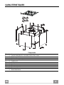 6
6
-
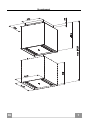 7
7
-
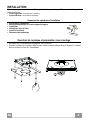 8
8
-
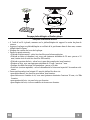 9
9
-
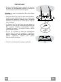 10
10
-
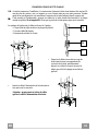 11
11
-
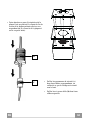 12
12
-
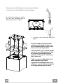 13
13
-
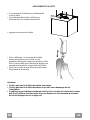 14
14
-
 15
15
-
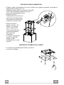 16
16
-
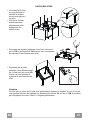 17
17
-
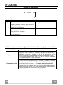 18
18
-
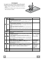 19
19
-
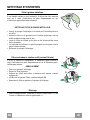 20
20
-
 21
21
-
 22
22
-
 23
23
-
 24
24
-
 25
25
-
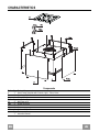 26
26
-
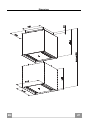 27
27
-
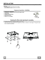 28
28
-
 29
29
-
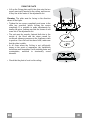 30
30
-
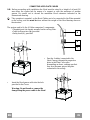 31
31
-
 32
32
-
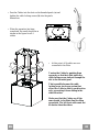 33
33
-
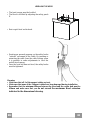 34
34
-
 35
35
-
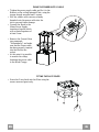 36
36
-
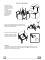 37
37
-
 38
38
-
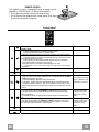 39
39
-
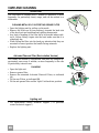 40
40
-
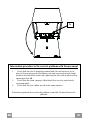 41
41
-
 42
42
-
 43
43
-
 44
44
-
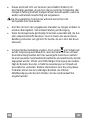 45
45
-
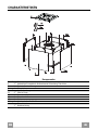 46
46
-
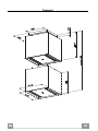 47
47
-
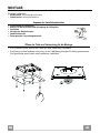 48
48
-
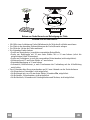 49
49
-
 50
50
-
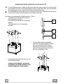 51
51
-
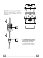 52
52
-
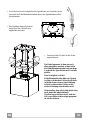 53
53
-
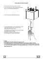 54
54
-
 55
55
-
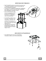 56
56
-
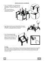 57
57
-
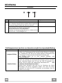 58
58
-
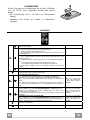 59
59
-
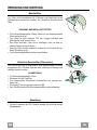 60
60
-
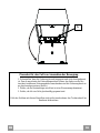 61
61
-
 62
62
-
 63
63
-
 64
64
-
 65
65
-
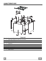 66
66
-
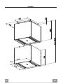 67
67
-
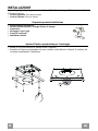 68
68
-
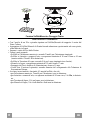 69
69
-
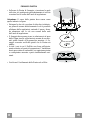 70
70
-
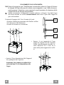 71
71
-
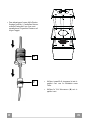 72
72
-
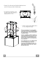 73
73
-
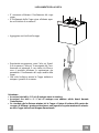 74
74
-
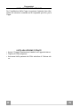 75
75
-
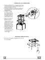 76
76
-
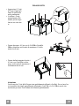 77
77
-
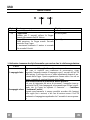 78
78
-
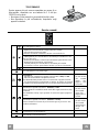 79
79
-
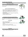 80
80
-
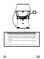 81
81
-
 82
82
-
 83
83
-
 84
84
-
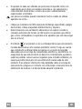 85
85
-
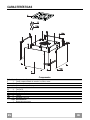 86
86
-
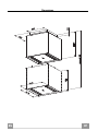 87
87
-
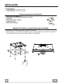 88
88
-
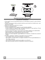 89
89
-
 90
90
-
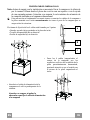 91
91
-
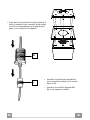 92
92
-
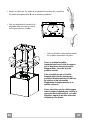 93
93
-
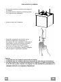 94
94
-
 95
95
-
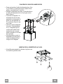 96
96
-
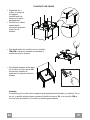 97
97
-
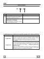 98
98
-
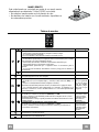 99
99
-
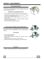 100
100
-
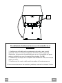 101
101
-
 102
102
-
 103
103
-
 104
104
-
 105
105
-
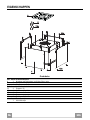 106
106
-
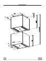 107
107
-
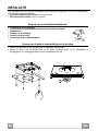 108
108
-
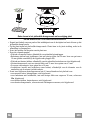 109
109
-
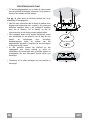 110
110
-
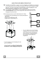 111
111
-
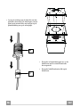 112
112
-
 113
113
-
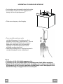 114
114
-
 115
115
-
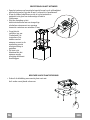 116
116
-
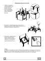 117
117
-
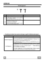 118
118
-
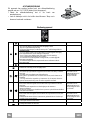 119
119
-
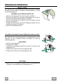 120
120
-
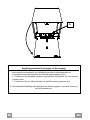 121
121
-
 122
122
-
 123
123
-
 124
124


ROBLIN EPSILONE 400 VERRE BL El manual del propietario
- Categoría
- Campanas de cocina
- Tipo
- El manual del propietario
En otros idiomas
Documentos relacionados
-
ROBLIN Apollon El manual del propietario
-
ROBLIN EDEN BOX El manual del propietario
-
-
-
-
-
-
-