Danby DR240WGLP El manual del propietario
- Tipo
- El manual del propietario

Model • M odèle • Modelo
OWNER’S USE AND CARE GUIDE
GUÍA DE UTILIZACIÓN Y CUIDADO PARA EL PROPIETARIO
MODEL • MODELO
05.06.14
COMPACT GAS RANGE
ESTUFAS DE GAS COMPACTAS
DR200WGLP • DR240WGLP
DANBY PRODUCTS LIMITED, GUELPH, ONTARIO, CANADA N1H 6Z9
DANBY PRODUCTS INC., FINDLAY, OHIO, USA 45840
COMPACT GAS RANGE
Owner’s Use and Care Guide .......................................1-32
• Important Safety Information
• Welcome
• Operation Instructions
• Care and Maintenance
• Installation Instructions
• Troubleshooting
• Warranty
ESTUFAS GAS COMPACTAS
Guía de utilización y cuidado para el propietario..........33-66
• Instrucciones de seguridad importantes
• Bienvenido
• Operación
• Cuidado y mantenimiento
• Instrucciones de instalación
• Diagnósticos de problemas
• Garantía

IMPORTANT SAFETY INFORMATION
READ ALL INSTRUCTIONS BEFORE USING
― Do not store or use gasoline or other fl ammable vapors and liquids in the vicinity of this or
any other appliance.
― WHAT TO DO IF YOU SMELL GAS
• Do not try to light any appliance.
• Do not touch any electrical switch
• Do not use any phone in your building.
• Immediately call your gas supplier from a neighbor’s phone. Follow the gas supplier’s
instructions.
• If you cannot reach your gas supplier, call the fi re department.
― Installation and service must be performed by a qualifi ed installer, service agency or the
gas supplier.
WARNING
If the information in this manual is not followed exactly, a fi re or explosion may result,
causing property damage, personal injury or death.
WARNING
• All ranges can tip.
• BURNS or other SERIOUS INJURIES can result.
• INSTALL and CHECK the anti-tip bracket following the instructions supplied in this manual.
To reduce the risk of tipping the range, the range must be secured by a properly installed anti-tip bracket.
See installation instructions for complete details before attempting to install.
To check if the bracket is installed and engaged properly, look underneath the range to see that the rear
leveling leg is engaged in the bracket. On some models, the storage drawer or kick panel can be removed
for easy inspection. If visual inspection is not possible, slide the range forward, confi rm the anti-tip bracket
is securely attached to the fl oor or wall, and slide the range back so the rear leveling leg is under the anti-
tip bracket.
If the range is pulled from the wall for any reason, always repeat this procedure to verify the range is
properly secured by the anti-tip bracket.
1

IMPORTANT SAFETY INFORMATION
READ ALL INSTRUCTIONS BEFORE USING
IMPORTANT SAFETY NOTICE
WARNING
The California Safe Drinking Water and Toxic Enforcement Act requires the Governor of California to publish a
list of substances known to the state to cause cancer, birth defects or other reproductive harm, and requires
businesses to warn customers of potential exposure to such substances.
The fi berglass insulation in self-clean ovens gives off a very small amount of carbon monoxide during the
cleaning cycle. Exposure can be minimized by venting with an open window or using a ventilation fan or hood.
READ AND FOLLOW THIS SAFETY INFORMATION CAREFULLY
SAVE THESE INSTRUCTIONS
WARNING
NEVER use this appliance as a space heater to heat or warm the room. Doing so may result in carbon monoxide
poisoning and overheating of the oven.
• Use this appliance for its intended purpose as described in this Owner’s Manual.
• Have your range installed and properly grounded by a qualifi ed installer in accordance with the provided installation
instructions. Any adjustment and service should be performed only by a qualifi ed gas range installer or service
technicians. Do not attempt to repair or replace any part of your range unless it is specifi cally recommended in this
guide.
• Your range is shipped from the factory set for use with natural gas. It can be converted for use with LP gas. If
required, these adjustments must be made by a qualifi ed technician in accordance with the installation instructions
and local codes. The agency performing this work assumes responsibility for the conversion.
• Have the installer show you the location of the range gas shut-off valve and how to turn it off if necessary.
• Plug your range into a 120-volt grounded outlet only. Do not remove the round grounding prong from the plug.
If in doubt about the grounding of the home electrical system, it is your responsibility and obligation to have an
ungrounded outlet replaced with a properly grounded, three prong outlet in accordance with the National Electrical
Code. Do not use an extension cord with this appliance.
• Before performing any service, unplug the range or disconnect the power supply at the household distribution panel
by removing the fuse or switching off the circuit breaker.
• Be sure all packing materials are removed from the range before operating to prevent ignition of these materials.
• Avoid scratching or impacting glass doors, cooktops or control panels. Doing so may lead to glass breakage. Do not
cook on a product with broken glass. Shock, fi re or cuts may occur.
• Do not leave children alone or unattended in an area where an appliance is in use. They should never be allowed to
climb, sit or stand on any part of the appliance.
• Do not store items of interest to children above a range or on the backguard of a range - children climbing on the
range to reach items could be seriously injured.
• Do not allow anyone to climb, stand or hang on the oven door, drawer or cooktop. They could damage the range or tip
it over causing severe injury or death.
2
GENERAL SAFETY INSTRUCTIONS
WARNING

IMPORTANT SAFETY INFORMATION
READ ALL INSTRUCTIONS BEFORE USING
GENERAL SAFETY INSTRUCTIONS (cont’d)
• Never block the vents (air openings) of the range. They provide the air inlets and outlets that are necessary for the
range to operate properly with correct combustion. Air openings are located at the rear of the cooktop, at the top and
bottom of the oven door, and at the bottom of the range under the warming drawer, lower oven drawer or kick panel.
• Use only dry pot holders—moist or damp pot holders on hot surfaces may result in burns from steam. Do not let pot
holders touch surface burners, burner grates, or oven heating elements. Do not use a towel or other bulky cloth in
place of pot holders.
• Be careful not to touch hot surfaces of the range. Potentially hot surfaces include burners, grates, cooktop,
backguard, oven and door interior and crevices around the oven door.
• Do not heat unopened food containers. Pressure could build up and the container could burst, causing an injury.
• Cook meat and poultry thoroughly - meat to at least an internal temperature of 160°F and poultry to at least an internal
temperature of 180°F. Cooking to these temperatures usually protects against foodborne illness.
• Do not store or use fl ammable materials in an oven or near the cooktop, including paper, plastic, pot holders, linens,
wall coverings, curtains, drapes and gasoline or other fl ammable vapors and liquids.
• Never wear loose-fi tting or hanging garments while using the appliance. Avoid storing commonly used items in
cabinets above the range and be careful when reaching over the range. Clothing in close proximity to burners or hot
surfaces may ignite causing severe burns.
• Do not let cooking grease or other fl ammable materials accumulate in or near the range. Grease in the oven or on the
cooktop may ingnite.
• Clean ventilating hoods frequently. Grease should not be allowed to accumulate on the hood or fi lter.
WARNING
WARNING
KEEP FLAMMABLE MATERIALS AWAY FROM THE RANGE
READ AND FOLLOW THIS SAFETY INFORMATION CAREFULLY
SAVE THESE INSTRUCTIONS
• Do not use water on grease fi res. Never pick up a fl aming pan. Turn the controls off. Smother a fl aming pan on a
surface burner by covering the pan completely with a well-fi tting lid, cookie sheet or fl at tray. If necessary, use a multi-
purpose dry chemical or foam-type fi re extinguisher.
• If there is a fi re in the oven during baking, turn the oven off and keep the door closed until the fi re goes out. If
necessary, use a multi-purpose dry chemical or foam-type fi re extinguisher.
• If there is a fi re in the oven during self-clean, turn the oven off and wait for the fi re to go out. Do not force the door
open. Introduction of fresh air at self-clean temperatures may lead to a burst of fl ame from the oven. Failure to follow
this instruction may result in severe burns.
WARNING
IN THE EVENT OF A FIRE, TAKE THE FOLLOWING STEPS
TO PREVENT THE FIRE FROM SPREADING
3

IMPORTANT SAFETY INFORMATION
READ ALL INSTRUCTIONS BEFORE USING
• Never leave the range unattended while a surface burner is ON. Foods, especially oily foods, may ignite resulting in
fi re that could spread to surrounding cabinets.
• Never leave oil unattended while frying. If allowed to heat beyond its smoking point, oil may ignite resulting in fi re that
may spread to surrounding cabinets. Use a deep fat thermometer whenever possible to monitor oil temperature.
• To avoid oil spillover and fi re, use a minimum amount of oil when shallow pan-frying and avoid cooking frozen foods
with excessive amounts of ice.
• Use proper pan size and avoid pans that are unstable or easily tipped. Select cookware that is matched to the size
of the burner. Burner fl ames should be adjusted so that they do not extend beyond the bottom of the pan. Excessive
fl ames may be hazardous.
• Always use the LITE position when igniting the top burners and make sure the burners have ignited.
• When using glass/ceramic cookware, make sure it is suitable for cooktop service; others may break because of
sudden changes in temperature.
• To minimize the possibility of burns, ignition of fl ammable materials and spillage, the handle of a container should be
turned toward the center of the range without extending over nearby burners.
• When preparing fl aming foods under a hood, turn the fan on.
• Do not use a wok with a round metal support ring. The ring may trap heat and block air to the burner resulting in a
carbon monoxide hazard.
• Do not attempt to lift the cooktop if your range has sealed surface burners. Doing so may damage the gas tubing to
the surface burners resulting in a gas leak and risk of fi re.
• Do not use aluminum foil to cover the grates or line any part of the cooktop. Doing so may result in carbon monoxide
poisoning, overheating of the cooktop surfaces, or a potential fi re hazard.
WARNING
COOKTOP SAFETY INSTRUCTIONS
READ AND FOLLOW THIS SAFETY INFORMATION CAREFULLY
SAVE THESE INSTRUCTIONS
WARNING
OVEN SAFETY INSTRUCTIONS
WARNING
NEVER cover any slots, holes, or passages in the oven bottom or cover an entire rack with materials such
as aluminum foil. Doing so blocks air fl ow through the oven and may cause carbon monoxide poisoning.
Aluminum foil linings may also trap heat, causing a fi re hazard.
• Stand away from the range when opening the oven door. Hot air or steam which escapes can cause burns to hands,
face and/or eyes.
• Keep the oven free from grease build-up. Grease in the oven may ignite.
• Place oven racks in desired location while oven is cool. If rack must be moved while oven is hot, do not let potholder
contact the hot heating element in the oven.
• Place oven racks in desired location while oven is cool. If rack must be moved while oven is hot, be careful to avoid
touching hot surfaces
4

READ ALL INSTRUCTIONS BEFORE USING
IMPORTANT SAFETY INFORMATION
READ AND FOLLOW THIS SAFETY INFORMATION CAREFULLY
SAVE THESE INSTRUCTIONS
• Pull the oven rack to the stop-lock position when loading and unloading food from the oven. This helps prevent burns
from touching hot surfaces of the door and oven walls.
• Do not leave items such as paper, cooking utensils or food in the oven when not in use. Items stored in an oven can
ignite.
• Do not leave items on the cooktop near the oven vent which is in the center of the backguard. Items may overheat
resulting in a risk of fi re or burns.
• When using cooking or roasting bags in the oven, follow the manufacturer’s directions.
• Never broil with door open. Open-door broiling is not permitted due to overheating of control knobs.
WARNING
OVEN SAFETY INSTRUCTIONS (cont`t)
• The purpose of the warming drawer is to hold hot cooked foods at serving temperature. Bacteria will grow very rapidly
in food that is between 40 and 140°F. Do not put cold food in the warming drawer. Do not keep food in the warming
drawer for more than 2 hours. Failure to follow these instructions may result in foodborne illness.
• Do not leave paper products, plastics, canned food or combustible materials in the drawer. They may ignite.
• Do not touch the heating element or the interior surface of the drawer. These surfaces may be hot enough to cause
burns.
• Use care when opening the drawer. Open the drawer a crack and let hot air or steam escape before removing or
replacing food. Hot air or steam that escapes can cause burns to hands, face and/ or eyes.
• Do not use aluminum foil to line the warming drawer. Foil is an excellent heat insulator and will trap heat beneath it.
This will upset the performance of the drawer and potentially cause a fi re hazard.
WARNING
WARMING DRAWER/ LOWER OVEN DRAWER
SAFETY INSTRUCTIONS (Some Models)
5

WELCOME
6
Welcome to the Danby family. We’re proud of our quality products, and we believe in dependable service, like you will fi nd
in this Owner’s Use and Care Guide, and like you will receive from our friendly customer service department. Best of all,
you will experience these values each and every time you use your Danby appliance. That’s important, because your new
appliance will be a part of your family for a long time.
Note the information below; you will need this information to obtain service under warranty.
To receive service, you must provide the original receipt.
Model No:
Serial No:
Date Purchased:
NEED HELP?
Before you call for service, here are a few things you can do to
help us serve you better:
Read this Owner’s Use and Care Guide:
It contains instructions to help you use and maintain your
appliance properly.
If you received a damaged appliance:
Immediately contact the retailer (or builder) that sold you the
appliance.
Save time and money:
Check the Troubleshooting section at the end of the guide
before calling. This section helps you solve common problems
that may occur.
If you do need service, you can relax, knowing help is only a
phone call away.
Tel: 1-800-26-
(1-800-263-2629)
WARNING
Read all safety instructions before using the product.
Failure to follow these instructions may result in fi re,
electric shock, serious injury or death.

OPERATION INSTRUCTIONS
USING THE GAS SURFACE BURNERS
Throughout this manual, features and appearance may vary from your model.
BEFORE LIGHTING A GAS BURNER
• Make sure all burners are in place.
• Make sure all grates on the range are properly placed before using any burner.
AFTER LIGHTING A GAS BURNER
• Do not operate the burner for an extended period of time without cookware on the grate. The fi nish on the grate may
discolor or chip without cookware to absorb the heat.
• Be sure the burners and grates are cool before you place your hand, a pot holder, cleaning cloths or other materials
on them.
HOW TO LIGHT A GAS SURFACE BURNER
• Make sure all the surface burners are placed in their respective positions.
• Push the control knob in and turn it to the LITE position.
• You will hear a little clicking noise - the sound of the electric spark igniting the burner.
• Turn the knob to adjust the fl ame size. If the knob stays at LITE, it will continue to click.
• When one burner is turned to LITE, all the burners spark. Do not attempt to
disassemble or clean around any burner while another burner is on. An electric shock
may result, which could cause you to knock over hot cookware.
HOW TO SELECT FLAME SIZE
• Watch the fl ame, not the knob, as you adjust heat. When fast heating is desired, the fl ame size on a gas burner
should match the cookware you are using.
• Flames larger than the bottom of the cookware will not result in faster heating and may be hazardous.
Push the control knob in and
turn it to the LITE position.
WARNING
Flames that are not covered by cookware may present a risk of burns or clothing
ignition. Never let fl ames extend beyond the sides of the cookware.
TOP-OF-RANGE COOKWARE
• Aluminum: Medium-weight cookware is recommended because it heats quickly and evenly. Most foods brown evenly
in an aluminum skillet. Use saucepans with tight-fi tting lids when cooking with minimum amounts of water.
• Cast-Iron: If heated slowly, most skillets will give satisfactory results.
• Enamelware: Under some conditions, the enamel of some cookware may melt. Follow cookware manufacturer’s
recommendations for cooking methods.
• Glass: There are two types of glass cookware—those for oven use only and those for top-of-range cooking
(saucepans, coffee and teapots). Glass conducts heat very slowly.
• Heatproof Glass Ceramic: Can be used for either surface or oven cooking. It conducts heat very slowly and cools
very slowly. Check cookware manufacturer’s directions to be sure it can be used on gas ranges.
• Stainless Steel: This metal alone has poor heating properties and is usually combined with copper, aluminum or
other metals for improved heat distribution. Combination metal skillets usually work satisfactorily if they are used with
medium heat as the manufacturer recommends.
IN CASE OF POWER FAILURE
• In case of a power failure, you can light the surface burners on your range with a match. Hold a lit match to the burner
ports, then slowly turn the control knob to the LITE position. Use extreme caution when lighting burners this way.
• Surface burners in use when an electrical power failure occurs will continue to operate normally.
7

OPERATION INSTRUCTIONS
USING THE OVEN
Throughout this manual, features and appearance may vary from your model.
OVEN CONTROLS
• Your oven is controlled by an OVEN TEMP knob. It can take up to 90 seconds before the
fl ame comes on.
• After the oven reaches the selected temperature, the oven burner maintains the selected
temperature.
OVEN TEMP
OVEN SHELF POSITIONS
Before you begin...
The shelves have stop-locks, so that when placed correctly on the shelf supports (A through
D), they will stop before coming completely out, and will not tilt.
When placing and removing cookware, pull the shelf out to the bump on the shelf support.
To remove a shelf, pull it toward you, tilt the front end up and pull it out.
To replace, place the end of the shelf (stop-locks) on the support, tilt up the front and push the shelf in.
NOTE: The shelf is not designed to slide out at the special low shelf (A) position.
POWER OUTAGE
• The oven or broiler cannot be lit during a power failure.
• If the oven is in use when a power failure occurs, the oven burner shuts off. This is because the fl ow of gas is
automatically stopped and will not resume until power is restored.
To avoid possible burns, place the shelves in the desired position before you turn the oven on.
WARNING
When you are using a rack in the lowest position (A), you will need to use caution
when pulling the rack out. We recommend that you pull the rack out several inches
and then, using two pot holders, pull the rack out by holding the sides of it. The rack
is low and you can be burned if you put your hand in the middle of the rack and pull
all the way out.
UPPER OVEN VENT
Your oven is vented through ducts at the rear of the range. Do not block these ducts when
cooking in the oven - it is important that the fl ow of hot air from the oven and fresh air to the
oven burner be uninterrupted. Avoid touching the vent openings or nearby surfaces during
oven or broiler operations - they may become hot.
• Handles of pots and pans on the cooktop may become hot if left too close to the vent.
• Do not leave plastic or fl ammable items on the cooktop - they may melt or ignite if left too
close to the vent.
• Do not leave closed containers of the cooktop. The pressure in closed containers may
increase, which may cause them to burst.
• Metal items will become very hot if they are left on the cooktop, and could cause burns.
Plastic items on the
cooktop may melt if left
too close to the vent. Vent
appearance and location
can vary.
8

OPERATION INSTRUCTIONS
To avoid possible burns, place the shelves in the desired position before you turn the oven on.
HOW TO SET YOUR OVEN FOR BAKING
1. Close the oven door. Then turn the OVEN TEMP knob to the desired temperature.
2. Check to see if the food is done at the minimum time on the recipe. Cook longer if necessary. Turn the OVEN TEMP
knob to OFF and remove the food.
OVEN SHELVES
Arrange the oven shelf or shelves in the desired locations while the
oven is cool. The correct shelf position depends on the kind of food
and the browning desired.
As a general rule, place most foods in the middle of the oven, on
either the shelf position B or C. See the chart for suggested shelf
positions.
PREHEATING
To preheat, set the oven at the correct temperature - selecting a higher temperature does not shorten the preheat time.
Preheat the oven for 10 minutes if the recipe calls for it. Preheat means bringing the oven up to the specifi ed temperature
vefore putting the food in the oven.
Preheating is necessary for good results when baking cakes, cookies, pastry and breads. For most casseroles and roasts,
preheating is not necessary.
THE TYPE OF MARGARINE WILL AFFECT BAKING PERFORMANCE
• Most recipes for baking have been developed using high-fat products such as butter or margarine (80% fat). If
you decrease the fat, the recipe may not give the same results as with a higher fat product.
• Recipe failure can result if cakes, pies, pastries, cookies, or candies are made with low-fat spreads. The lower the fat
content of a spread product, the more noticeable these differences become.
• Federal standards require products labeled “margarine” to contain at least 80% fat by weight. Low-fat spreads, on the
other hand, contain less fat and more water. The high moisture content of these spreads affects the texture and fl avor
of baked goods. For best results with your old favorite recipes, use margarine, butter or stick spreads containing at
least 70% vegetable oil.
USING THE OVEN FOR BAKING
Place most foods in the
middle of the oven.
Type of Food Shelf Position
Angel food cake A
Biscuits, muffi ns or cup-
cakes
B or C
Cookies C or D
Brownies B or C
Layer cakes B or C
Bundt or pound cakes B
Pies or pie shells B or C
Frozen pies (on cookie
sheet)
B or C
Casseroles B or C
9
OVEN LIGHT
On some models: Use the switch on the lower control panel to turn the light on or off.
On some models: Press the Oven LIght button found on the upper control panel to turn the light on or off.

OPERATION INSTRUCTIONS
USING THE OVEN FOR BAKING
10
BAKING PANS
Use the proper baking pan. The type of fi nish on the pan determines the amount of browning that will occur.
• Glass baking dishes also absorb heat. When baking in glass baking dishes, lower the temperature by 25 °F and use
the recommended cooking time in the recipe. This is not necessary when baking pies or casseroles.
• Dark, rough, or dull pans absorb heat resulting in a browner, crisper crust. Use this type for pies.
• Shiny, bright and smooth pans refl ect heat, resulting in a lighter, more delicate browning. Cakes and cooking require
this type of pan.
PAN PLACEMENT
For even cooking and proper browning, there must be enough room for air circulation in the oven. Baking results will be
better if baking pans are centered as much as possible rather than being placed to the front or to the back of the oven.
Pans should not touch each other or the walls of the oven. Allow 1 to 1 1/2 inches of space between pans as well as from
the back of the oven, the door and the sides.
If you need to use two shelves stagger the pans so one is not directly above the other.
COOKIES
Flat cookie sheets (without sides) produce better-looking cookies. Cookies baked in a jelly
roll pan (short sides all around) may have darker edges and pale or light browning may
occur.
Do not use a cookie sheet so large that it touches the walls or the door of the oven. Never
entirely cover a shelf with a large cookie sheet.
PIES
For best results, bake pies in dark, rough or dull pans to produce a browner, crisper crust.
Frozen pies in foil pans should be placed on an aluminum cookie sheet for baking, since the shiny foil pan refl ects heat
away from the pie crust; the cookie cheet helps retain it.
Check the recipe to make sure the pan size used is the one recommended.
CAKES
When baking cakes, warped or bent pans will cause uneven baking results and poorly shaped products.
A cake baked in a pan larger than the recipe recommends will usually be crisper, thinner and drier than it should be.
If baked in a pan smaller than recommended, it may be undercoked and batter may overfl ow.
Check the recipe to make sure the pan size used is the one recommended.
DON`T PEEK
Set the timer for the estimated cooking time and do not open the door to look at your food. Most recipes provide minimum
and maximum baking times such as ``bake 30-40 minutes``.
DO NOT open the door to check until the minimum time. Opening the oven door frequently during cooking allows heat to
escape and makes baking times longer. Your baking results may also be affected.

OPERATION INSTRUCTIONS
USING THE OVEN FOR BAKING
ALUMINUM FOIL
Do not use aluminum foil to line oven bottoms. The foil will trap heat below and upset the performance of the oven. Foil
can melt and permanently damage the oven bottom. Damage from improper use of aluminum foil is not covered by the
product warranty.
Foil may be used to catch spills by placing a sheet on a lower rack, several inches below the food. Do not use more foil
than necessary and never entirely cover an oven rack with aluminum foil. Keep foil at least 1 to 1 1/2 inches from oven
walls to prevent poor heat circulation.
As your oven heats up, the temperature change of the air in the oven may cause water droplets to form on the door glass.
These droplets are harmless and will evaporate as the oven continues to heat up.
OVEN MOISTURE
USING THE OVEN FOR ROASTING
Roasting is cooking using dry heat. Tender meat or poultry can be roasted uncovered in your oven. Roasting
temperatures, which should be low and steady, keep spattering to a minimum.
Roasting is really a baking procedure used for meats. Roasting is easy: just follow these directions:
1. Place the shelf in the A or B position. No preheating is necessary.
2. Check the weight of the meat. Place it fat side up (or for poultry, breast-side-up) on a
roasting rack in a shallow pan. The melting fat will baste the meat. Select a pan as close
to the size of the meat as possible. Line the pan with aluminum foil when using the pan
for marinating, cooking with fruits, cooking heavily cured meats or basting food during
cooking.
3. Turn the OVEN TEMP knob to the desired setting.
4. After roasting is complete, turn the OVEN TEMP knob to OFF and then remove the food
from the oven.
ADJUST THE OVEN THERMOSTAT - EASY TO DO YOURSELF
You may fi nd that your new oven cooks differently than the one it replaced. Use you new oven for a few weeks to
become more familiar with it. If you still think your new oven is too hot or too cold, you can adjust the thermostat
yourself.
Do not use thermometers, such as those found in grocery stores, to check the temperature setting of your oven.
These thermometers may vary 20-40°F.
Note: This adjustment will not affect the broiling temperatures. The adjustment will be retained after a power
failure.
11
Place the shelf in the A or
B position.

OPERATION INSTRUCTIONS
TO ADJUST THE THERMOSTAT WITH THIS TYPE OF KNOB
1. Pull the OVEN TEMP knob off the range and look at the back side. To make an
adjustment, loosen (approximately one turn), but do not completely remove, the two
screws on the back of the knob.
2. With the back of the knob facing you, hold the outer edge of the knob with one hand
and turn the front of the knob with the other hand.
To increase the oven temperature, move the top screw toward the right. You will hear a
click for each notch you move the knob.
To decrease the oven temperature, move the top screw toward the left.
Each click will change the oven temperature approximately 10°F. (The range is plus
or minus 60°F from the arrow.) We suggest that you make the adjustment one click
from the original setting and check oven performance before making any additional
adjustments.)
3. After the adjustment is made, retighten screws so that they are snug, but be
careful not to over-tighten.
4. Replace the knob, matching the fl at area of the knob to the shaft, and check
performance.
L
O
O
S
E
N
S
C
R
E
W
S
T
O
R
O
T
A
T
E
M
A
K
E
C
O
O
L
E
R
M
A
K
E
H
O
T
T
E
R
OVEN TEMP
Front of OVEN TEMP knob
(knob appearance may vary)
Back of OVEN TEMP knob
ADJUST THE OVEN THERMOSTAT - EASY TO DO YOURSELF
USING THE OVEN FOR BROILING
Broiling is cooking food by direct heat from above the food. Most fi sh and tender cuts of meat can be broiled.
Follow these steps to keep spattering and smoking to a minimum.
Your range has a compartment below the oven for broiling. A specially designed broiler pan allows dripping fat to
drain away from the food.
Both the oven door and broiler compartment drawer should be closed during broiling.
1. You can change the distance of hte food from the heat source by positioning the broiler
rack in the broiler compartment.
- A (bottom of broiler compartment),
- B (center of broiler comparment),
- C (top of broiler compartment).
Most broiling should be done in position A.
2. Preheat the broiler for best results.
3. If the meat has fat or gristle around the edge, cut vertical slashes through it about 2 inches
apart, but don’t cut into the meat. We recommend that you trim the fat to prevent excessive
smoking, leaving a layer about 1/8 inch thick.
4. Close the oven door and broiler compartment drawer.
5. Turn the OVEN TEMP knob to BROIL.
6. Turn most foods once during cooking. Time foods for about one-half the total cooking time,
turn food, then continue to cook to completion.
7. Turn the OVEN TEMP knob to OFF. Remove the broiler pan from the broiler rack and
serve the food immediately. Leave the pan outside the range to cool.
HOW TO SET YOUR OVEN FOR BROILING
12
Front of OVEN TEMP knob
(knob appearance may vary)
Back of OVEN TEMP knob

OPERATION INSTRUCTIONS
USING THE OVEN FOR BROILING (cont’d)
HOW TO SET THE BROILER COMPARTMENT (on some models)
Both the oven and broiler compartment doors must be closed during broiling.
Turn most foods once during cooking (the exception is thin fi llets of fi sh; oil one side, place that
side down on the broiler grid and cook without turning until done). Time foods for about one-
half the total cooking time, turn food, then continue to cook until done.
1. You can change the distance of the food from the heat source by positioning the broiler
pan and grid on one of three rack positions in the broiler compartment - A (bottom of broiler
compartment), B (middle) and C (top).
2. Preheating the broiler or oven is not necessary and can produce poor results.
3. If meat has fat or gristle around the edge, cut vertical slashes through both about 2 inches
apart. If desired, the fat may be trimmed, leaving a layer about 1/8 inches thick.
4. Arrange the food on the grid and position the broiler pan on the appropriate rack in
the oven or broiling compartment. Placing food closer to the fl ame increases exterior
browning of the food, but also increases spattering and the possibility of fats and meat
juices igniting.
5. Close the oven and broiler compartment door.
6. Turn the OVEN CONTROL knob to BROIL.
7. When broiling is fi nished, turn the OVEN CONTROL knob to OFF. Remove the broiler pan
from the broiler compartment and serve the food immediately. Leave the pan outside the
range to cool.
You can use aluminum foil to line your broiler pan and broiler grid. However, you must mold
the foil tightly to the grid and cut slits in it just like the grid.
ALUMINUM FOIL
BROILING COMPARTMENT GUIDE SUGGESTIONS
Both the oven and broiler compartment doors must be closed during broiling.
• Always use the broiler pan and grid that comes with your range. It is designed to minimize smoking and spattering by
trapping juices in the shielded lower part of the pan.
• For steaks and chops, slash fat evenly around the outside edges of the meat. To slash, cut crosswise through the
outer fat surface just to the edge of the meat. Use tongs to turn the meat over to prevent piercing the meat and losing
juices.
• If desired, marinate meats or chicken before broiling; or you can brush with barbecue sauce in the last 5-10 minutes
only.
• When arranging the food on the pan, do not let fatty edges hang over the sides because dripping fat could soil the
oven.
• The broiler compartment does not need to be preheated. However, for very thin foods, or to increase browning,
preheat if desired.
• Frozen steaks can be broiled by positioning the rack at the next lowest rack position and increasing the cooking time
given in this guide 1 1/2 times per side.
13

OPERATION INSTRUCTIONS
USING THE OVEN FOR BROILING (cont’d)
The USDA recommends the following minimum safe internal temperatures:
• Raw beef, pork, lamb and veal steaks or chops: 145 °F as measured with a food thermometer before removing
meat from the heat source. For safety and quality, allow meat to reast for at least three minutes before carving or
consuming.
• Raw ground beef, pork, lamb or veal: 160 °F as measured with a food thermometer.
• Poultry: 165 °F as measured with a food thermometer.
• For more information, visit: www.isitdoneyet.gov or call toll free to the USDA meat and poultry hotline at 1-888-674-
6854.
BROILING COMPARTMENT GUIDE SUGGESTIONS (cont’d)
CARE AND MAINTENANCE
Be sure electrical power is off and all surfaces are cool before cleaning any part of the range.
Proper care and cleaning are important so that your range will give you effi cient and satisfactory service. Follow
these directions carefully in caring for your range to assure safe and proper maintenance.
WARNING
• If your range is removed for cleaning, servicing or any reason, be sure the anti-
tip device is re-engaged properly when the range is replaced. Failure to take
this precaution could result in tipping of the range and cause injury.
• To check if the bracket is installed and engaged properly, carefully tip the range
forward. The bracket should stop the range within 4 inches. If it does not, the
bracket must be reinstalled.
• If the range is pulled from the wall for any reason, always repeat this procedure
to verify that the range is properly secured by the anti-tip bracket.
CARE AND CLEANING OF THE RANGE
LIFT-UP COOKTOP (on models with standard twin burners)
• Clean the area under the cooktop often. Built-up soil, especially grease, may catch on
fi re.
• To make cleaning easier, the cooktop may be lifted up.
• NOTE: Do not lift the cooktop on sealed burner models. Lifting the cooktop can lead to
damage and improper operation of the range.
To raise the cooktop:
1. Be sure the burners are turned off.
2. Remove the grates.
3. Grasp the two front burner wells and lift up.
• Clean under the cooktop with hot, soapy water and a clean cloth. If you removed your
surface burners while cleaning, make sure they are properly seated when replacing
them.
• After cleaning, lower the cooktop (be careful not to pinch your fi ngers).
Some models have dual
support rods that will hold
the cooktop up while you
clean underneath it.
14

CARE AND MAINTENANCE
CARE AND CLEANING OF THE RANGE
BURNER GRATES
Your range has two or three professional-style double grates. These grates are position-
specifi c. For maximum stability, these grates should only be used in their proper position; they
cannot be interchanged left to right or front to back. For convenience, the undersides of the left
and right grates are marked “LEFT FRONT” and “RIGHT FRONT”. Make sure the front portion
of both grates is in front. The middle grate has a bow in front. Make sure the bowed portion
is toward the front of the range. in addition, the middle grate is supported by the left nd right
grates and must be installed LAST for stability.
Cleaning
• Lift out when cool. Grates should be washed regularly and, of course, after spillovers. Wash them in hot, soapy water
and rinse with clean water. When replacing the grates, be sure they are positioned securely over the burners.
• Replace the grates so that continuous arcs are formed with the center ribs of all three grates.
• Do not operate a burner for an extended period of time without cookware on the grate. The fi nish on the grate may
chip without cookware to absorb the heat.
• To get rid of burned-on food, place the grates in a covered container. Add 1/4 cup ammonia and let soak several hours
or ovenight. Wash, rinse well and dry.
• Although they are durable, the grates will gradually lose their shine, regardless of the best care you can give them.
This is due to their continual exposure to high temperatures. You will notice this sooner with lighter color grates.
• NOTE: Do not clean the grates in a a self-cleaning oven.
STANDARD TWIN BURNER ASSEMBLIES (on some models)
For cleaning information on sealed burners, see section below. Sealed
burner cooktops do not lift up.
• On models with standard twin burners, the cooktop lifts up for easy access.
• Turn all contols OFF before removing burner parts and rip pans (if so
equipped).
• The burner grates and drip pans can be lifted off, making them easy to
clean.
• The holes in the surface burners of your range must be kept clean at all
times for proper ignition and an even, unhampered fl ame.
• You should clean the surface burners routinely, especially after bad spill-
overs, which could clog these holes.
• Wipe off surface burners. If heavy spillover occurs, remove the surface
burners from the range. Burners lift out for cleaning. Lift up the cooktop and
then lift out the surface burners.
• To remover burned-on food, soak the surface burner in a solution of mild liq-
uid detergent and hot water. Soak the surface burner for 20 to 30 minutes.
• For more stubborn stains, use a cleanser. Rinse well to remove any traces
of the cleanser that might clog the surface burner openings.
• Do not use steel wool because it will clog the surface burner openings and
scratch the surface burners. if the holes become clogged, clean them with a
sewing needle or twist-tie.
• Before putting the surface burner back, shake out excess water and then
dry it thoroughly by setting it in a warm oven for 30 minutes. Then place it
back in the range, making sure it is properly seated and level.
• Check the fl ame pattern of each burner. If the fl ames are “jumpy” (not
steady), clean the holes again with a sewing needle or twist-tie.
Clean these holes thoroughly on each side.
Do not operate the cooktop without all
burner parts, drip pans (if so equipped)
and grates in place.
CAUTION
15

CARE AND CLEANING OF THE RANGE (cont’d)
CARE AND MAINTENANCE
• Remove the grates an lift out the drip pans. Drip pans can be cleaned in a dishwasher or
by hand.
• When replacing the drip pans, make sure they are in the correct position.
• Place them in a covered container. Add 1/4 cup ammonia and let soak several hours or
overnight. Wash, rinse well and dry.
DRIP PANS (if so equipped)
Do not clean the drip pans in a self-cleaning oven.
CAUTION
Cooktop Surface
• To avoid damaging the porcelain-enamel surface of the cooktop and to prevent it from
becoming dull, clean up spills right away. Foods with a lot of acid (tomatoes, sauerkraut,
fruit juices, etc.) or foods with high sugar content could cause a dull spot if allowed to set.
• When the surface has cooled, wash and rinse. For other spills such as fat spatterings,
wash with soap and water once the surface has cooled. Then rinse and polish with a dry
cloth.
• NOTE: For stainless steel cooktops, refer to the Stainless steel surfaces section.
Oven Air Vents
• Never block the vents (air openings of the range.
They provide the air inlet and outlet that are neces-
sary for the range to operate properly with correct
combustion.
• Air openings are located at the rear of the cooktop,
at the top and bottom of the oven door, and at the
bottom of the range.
Vent appearance and location vary.
Lower Control Panel (Front Manifold Panel) and Knobs
• It is a good idea to wipe the control panel after each use of the oven. Use a damp cloth to
clean or rinse. For cleaning, use mild soap and water or a 50/50 solution of vinegar and
water. For rinsing, use clean water. Polish dry with a soft cloth.
• Do not use abrasive cleansers, strong liquid cleaners, plastic scouring pads or oven
cleaners on the control panel - they will damage the fi nish.
• Do not try to bend knobs by pulling them up or down or by hanging a towel or other such
loads. This can damage the gas valve shaft.
• The control knobs may be removed for easier cleaning.
• Make sure the knobs are in the OFF positions and pull them straight off the stems for
cleaning.
• The knobs can be cleaned in a dishwasher or they may also be washed with soap and
water. Make sure the insides of the knobs are dry before replacing.
• Replace the knobs in the OFF position to ensure proper placement.
• Metal parts can be cleaned with soap and water. Do not use steel wool, abrasives, am-
monia, acids or commercial oven cleaners. Dry with a soft cloth.
• NOTE: Knobs are not interchangeable. Be sure to reinstall the knobs to the original loca-
tion.
Surface burner knob
Lower oven knob
(on some models)
16

CARE AND MAINTENANCE
CARE AND CLEANING OF THE RANGE (cont’d)
OVEN SHELVES AND BROILER RACK
• The shelves and broiler rack can be cleaned by hand using soap and water or with an
abrasive cleaner or steel wool. After cleaning, rinse the shelves and broiler rack with
clean water and dry with a clean cloth.
• After cleaning, grease all oven rack edges with a light coating of vegetable oil. This will
help maintain the ease of sliding the racks in and out of the oven.
REMOVABLE OVEN BOTTOM
Knurled screw
(on some models)
• First remove the shelves from the oven. The oven bottom lifts from the front.
To remove:
1. On models so equipped, remove the knurled screw in the front of the oven bottom.
2. Grasp each side of the oven bottom and push it back.
3. Lift the front up and pull it out of the oven.
To replace:
1. Grasp each side of the oven bottom and guide its rear tabs into the slots in the back of
the oven.
2. Lower the oven bottom and pull it forward until it is secure under the front oven fl oor
edge.
3. On models so equipped, replace the knurled screw in the front of the oven bottom.
• NOTE: If the oven bottom is replaced incorrectly, it may warp and cause undesirable
baking results.
OVEN BOTTOM
• The oven bottom has a porcelain-enamel fi nish. To make cleaning easier, protect the oven bottom from excessive
spillovers by placing a cookie sheet on the rack below the rack you are cooking on. This is particularly important when
baking a fruit pie or other foods with a high acid content. Hot fruit fi llings or other foods that are highly acidic (such as
tomatoes, sauerkraut and sauces with vinegar or lemon juice) may cause pitting and damage to the porcelain-enamel
surface and should be wiped up immediately.
• To clean up spillovers, use soap and water, an abrasive claner or soap-fi lled scouring pad. Rinse well to remove any
soap before self-cleaning.
BROILER COMPARTMENT
• The broiler pan is held in place in the broiler rack.
To remove the broiler pan:
1. Gently pull forward on the drop down broiler door.
2. Pull the broiler rack with pan forward until the rack stops. Grasp the broiler pan and
remove it from the broiler rack.
To replace the broiler pan:
1. Slide the broiler pan onto the rack and push both the broiler pan and the rack all the way
into the broiler compartment.
2. Close the broiler door.
If a spillover occurs int he broiler compartment, allow the compartment to cool fi rst. You can
clean the compartment with soap and water, a mild abrasive cleanser, soap-fi lled scouring
pads or an oven cleaner following package directions.
17
Knurled screw
(on some models)

CARE AND MAINTENANCE
• The gasket is designed with a gap at the bottom to allow for proper air circulation.
• Do not rub or clean the door gasket - it has an extremely low resistance to abrasion.
• If you notice the gasket becoming worn, frayed or damaged in any way or if it has be-
come displaced on the door, you should have it replaced.
TO CLEAN THE DOOR:
To clean the inside of the door:
• Do not allow excess water to run into any holes or slots in the door.
• Wipe dishwashing detergent oven any baked-on spatters on the glass. Use a single sided safety razor blade to clean
it off. Then wipe over the glass with a soapy cloth to remove any residue and dry off.
• The area outside the gasket can be cleaned with a soap-fi lled plastic scouring pad.
To clean the outside of the door:
• Use soap and water to thoroughly clean the top, sides and front of the oven door. Rinse well. You may also use a
glass cleaner to clean the glass on the outside of the door.
• Spillage of marinades, fruit juices, tomato sauces and basting materials containing acids may cause discoloration and
should be wiped up immediately. When the surface is cool, clean and rinse.
• Do not use oven cleaners, cleansing powders or harsh abrasives on the outside of the door.
BROILER PAN AND GRID
• After broiling, remove the broiler pan from the oven. Remove the grid from the pan.
Carefully pour out grease from the pan into a proper container. Wash and rinse the
broiler pan and grid in hot water with a soap-fi lled or plastic scouring pad.
• If food has burned on, sprinkle the grid with detergent while hot and cover with wet paper
towels or a dishcloth. Soaking the pan will remove burned on foods.
• Do not store a soiled broiler pan and grid anywhere in the range.
Slot
Hinge
lock
Upper hinge
arm
Lower hinge
arm
The oven door is removable, but it is heavy. You may need help removing and
replacing the door.
To remove the door:
1. Open the door to the full open position.
2. Pull the hinge locks up over the hinge hooks on both sides. You may need
to use a fl at-blade screwdriver to lift hinge locks up.
3. Grasp the door fi rmly on each side, lift slightly and pull it straight out and
away from the oven.
To replace the door:
1. Firmly grasp both sides of the door at the top.
2. Insert and seat the upper and lower hinge arms into the oven slots.
3. Push the hinge locks down from the hinge hooks.
4. Close the oven door and make sure it is working properly. If it is not
working properly, remove and replace it following the above steps.
DO NOT ATTEMPT TO CLOSE THE DOOR UNTIL THIS STEP IS
COMPLETE. THE HINGE OR DOOR COULD BE DAMAGED.
LIFT-OFF OVEN DOOR
18
Slot
Hinge
lock
Upper hinge
arm
Lower hinge
arm

CARE AND MAINTENANCE
PORCELAIN OVEN INTERIOR
• NOTE: Wait for range to cool before cleaning.
• With proper care, the porcelain enamel interior will retain its attractive fi nish for many
years.
• Soap and water will normally do the job. Heavy spattering or spillovers may require
cleaning with a mild abrasive cleanser. Soapy, wet pads may also be used. Do not
allow food spills with a high sugar or acid content (such as milk, tomatoes, sauerkraut,
fruit juices or pie fi lling) to remain on the surface. They may cause dull spots even after
cleaning.
• Household ammonia may make the cleaning job easier. Place 1/2 cup ammonia in a
shallow glass pan and leave in a cold oven overnight. The ammonia fumes will help
loosen the burned-on grease and food.
• When necessary, you may use a commercial oven cleaner. Follow the package
directions.
Cautions about using spray-on oven cleaners:
• Do not spray the oven cleaner on the electrical controls and switches, because it could cause a short circuit and result
in sparking or fi re.
• Do not allow a fi lm from the cleaner to remain on the temperature sensor - it could cause the oven to heat improperly.
(The sensor is located at the top of the oven.) Carefully wipe the bulb clean after each oven cleaning, being careful
not to move the sensor since a change in its position could affect how the oven bakes.
• Do not spray any oven cleaner on the outside oven door, handles or any exterior surface of the oven, cabinet or
painted surfaces. The cleaner can damage these surfaces.
Painted Surfaces
Painted surfaces include the sides, control panel and door. Clean these with soap and water or a vinegar and water
solution. Do not use commercial oven cleaners, cleansing powders, steel wool or harsh abrasives on any painted surface.
OVEN LIGHT REPLACEMENT (on some models)
WARNING
SHOCK OR BURN HAZARD
Before replacing the oven light bulb, disconnect the electrical power to the range at the main fuse or circuit
breaker panel. Failure to do so may result in electric shock or burn. Be sure to let the light cover and bulb cool
completely.
Be sure to let the light cover and bulb cool completely.
To remove the cover:
1. Twist lens counterclockwise about a quarter turn to remove. Do not remove any screws
to remove the cover.
2. Replace bulb with a 40-watt appliance bulb or two-prong halogen bulb, as appropriate.
To replace the cover:
1. Line up tabs of lens in front of tabs on housing and rotate clockwise to engage.
19

BEFORE YOU BEGIN
Read these instructions completely and carefully.
Installation of this range must conform with local codes, or in the absence of local codes, with the National Fuel Gas
Code, ANSI Z223.1/NFPA 54, latest edition. This range has been design-certifi ed by CSA International according to ANSI
Z21.1, latest edition.
As with any appliance using gas and generating heat, there are certain safety precautions you should follow. You will fi nd
these precautions in the Important Safety Information section in the front of this manual. Read them carefully.
IMPORTANT - Save these instructions for local electrical inspector’s use
IMPORTANT - Observe all governing codes and ordinances.
Note to Installer - Leave these instructions with the appliance after installation is completed.
Note to Consumer - Keep this Owner’s Manual and Installation Instructions for future reference.
Note - This appliance must be properly grounded.
Servicer - The electrical diagram is attached to the back of the range.
Mobile home - additional installation requirements:
The installation of this range must conform to the Manufactured Home Construction and Safety Standard, Title 24 CFR,
Part 3280 (formerly the Federal Standard for Mobile Home Construction), use the Standard for Manufactured Home
Installations, ANSI A225, 1/NFPA 501A or with local codes.
Mobile home installations require:
When this range is installed in a mobile home, it must be secured to the fl oor during transit. Any method of securing the
range is adequate as long as it conforms to the standards listed above.
The oven light bulb is covered with a removable glass cover that is held in place
with a bail-shaped wire. Remove the oven door, if desired, to reach the cover
easily.
Be sure to let the light cover and bulb cool completely.
To remove the cover:
1. Hold a hand under the cover so it doesn’t fall when released. With the fi ngers
of the same hand, fi rmly push back the wire cover holder. Lift off the cover. Do
not remove any screws to remove the cover.
2. Do not touch the hot bulb with a wet cloth. Replace the bulb with a 40-watt
appliance bulb.
To replace the cover:
1. Place it into the groove of the light receptacle. Pull the wire forward to the center of the cover, until it snaps into place.
When in place, the wire holds the cover fi rmly. Be certain that the wire is in the depression in the center of the cover.
2. Connect the electrical power to the range.
Wire cover holder
OVEN LIGHT REPLACEMENT (on some models)
In the Commonwealth of Massachusetts:
• This product must be installed by a licensed plumber of gas fi tter.
• When using ball type gas shut-off valves, they shall be the T-handle type
• A fl exible gas connector, when used, must not exceed 3 feet.
20
Wire cover holder
CARE AND MAINTENANCE
INSTALLATION INSTRUCTIONS

INSTALLATION INSTRUCTIONS
FOR YOUR SAFETY
Do not store or use combustible materials, gasoline or other fl ammable vapors and liquids in the vicinity of this
or any other appliance.
If you smell gas:
1. Open windows.
2. Don’t touch electrical switches.
3. Extinguish any open fl ame.
4. Immediately call your gas supplier.
TOOLS YOU WILL NEED
MATERIALS YOU WILL NEED
• Gas-line shut-off valve
• Pipe joint sealant or UL-approved pipe thread tape with Tefl on* that resists action of natural and LP gases
• Flexible metal appliance connector (1/2” I.D.) A 5 foot length is recommended for ease of installation but other lengths
are acceptable. Never use an old connector when installing a new range.
• Flare union adapter for connection to gas supply line (3/4” or 1/2” NPT x 1/2” I.D.)
• Liquid leak detector or soapy water
• Lag bolt or 1/2” O.D. sleeve anchor (for concrete fl oors only).
*Tefl on: Registered trademark of DuPont.
)ODWEODGHVFUHZGULYHU
3LSHZUHQFKHV
RQHIRUEDFNXS
3KLOOLSVVFUHZGULYHU
2SHQHQGRU
DGMXVWDEOHZUHQFK
3HQFLODQGUXOHU
/HYHO
'ULOODZORUQDLO
21

INSTALLATION INSTRUCTIONS
INSTALLATION SAFETY INSTRUCTIONS
Read these instructions completely and carefully. Failure to follow these instructions can result in electrical
shock, fi re, serious injury, or death.
• Improper installation, ajustment, alteration, service or maintenance can cause injury or property damage. Refer to this
manual. For assistance or additional information, consult a qualifi ed installer, service agency, manufacturer (dealer) or
the gas supplier.
• Never reuse old fl exible connectors. The use of old fl exible connectors can cause gas leaks and personal injury. Al-
ways use NEW fl exible connectors when installing a gas appliance.
• Leak testing of the appliance shall be conducted according to the manufacturer instructions.
• Remove all packing material and literature from oven before connecting gas and electrical supply to range.
• Do not attempt to operate the oven of this range during a power failure (Electric Ignition Models only).
• Have your range installed by a qualifi ed installer.
• Your range must be electrically grounded accordance with local codes or, in the absence of local codes, in accor-
dance with the National Electrical Code (ANSI/NFPA 70, latest edition).
• Before installing your range on linoleum or any other synthetic fl oor covering, make sure the fl oor covering can with-
stand 180° F without shrinking, warping or discoloring. Do not install the range over carpeting unless a sheet of 1/4”
thick plywood or similar insulator is placed between the range and carpeting.
• Make sure the cabinets, fl oor, and wall coveringsaround the range can withstand heat generated by the range up to
200° F.
• Avoid placing cabinets above the range. To reduce the hazard caused by reaching over the open fl ames of operating
burners, install a ventilation hood over the range that projects forward at least 5” beyond the front of the cabinets.
• The ventilating hood must be constructed of sheet metal not less than 0.0122” thick. Install above the cooktop with
a clearance of not less than 1/4” between the hood and the underside of the combustible material or metal cabinet.
The hood must be at least as wide as the appliance and centered over the appliance. Clearance betwen the cooking
surface and the ventilation hood surface must never be less than 24”.
Exception: Installation of a listed microwave oven or cooking appliance over the cooktop shall conform to the
installation instructions packed with that appliance.
• If cabinets are placed above the range, allow a minimum clearance of 30 “ betwen the cooking surface and the bot-
tom of unprotected cabinets.
• If a 30” clearance between cooking surface and overhead combustible material or metal cabinets cannot be main-
tained, protect the underside of the cabinets above the cooktop with not less than 1/4” insulating miliboard covered
with sheet metal not less than 0.0122” thick. Clearance between the cooking surface and protected cabinets MUST
NEVER BE LESS THAN 24”.
• The vertical distance from the plane of the cooking surface to the bottom of adjacent overhead cabinets extending
closer than 1” to the plane of the range sides must not be less than 18”. (See the Dimensions and Clearances Illustra-
tion in this section).
WARNING
22

INSTALLATION INSTRUCTIONS
DIMENSIONS AND CLEARANCES
Provide adequate clearances between the range and adjacent combustible surfaces. These dimensions must be met for
safe use of your range. The placement of the power outlet and the opening of the piping (refer to Locations of Gas and
Electric) can be adjusted to comply with the specifi c requirements.
The range may be placed with 0” clearance below cooktop and at the back wall.
0RGHOV $ % & '
:LGH
øµ
:LGH
øµ
$
øµ
'
0D[LPXPGHSWK
IRUFDELQHWVDERYH
FRXQWHUWRSV
0LQLPXPWR
FDELQHWVRQ
HLWKHUVLGH
RIUDQJH
0LQLPXP
%
&
0LQLPXPWRZDOORQ
HLWKHUVLGHRIUDQJH
DERYHKHLJKW
7RFDELQHWVEHORZ
FRRNWRSDQGDWWKH
UDQJHEDFN
)URQWHGJHRI
WKHUDQJHVLGH
SDQHOIRUZDUG
IURPWKH
FDELQHW
To cabinets below
cooktop and at the
range back
Maximum depth
for cabinets above
countertops
Minimum to
cabinets on
either side
of range
Minimum to wall on
either side of range
above 36” height
Front edge of
the range side
panel forward
from the
cabinet
Minimum
23
Models A B C D
20” wide 20” 20 ⅜” 2” 41”
24” wide 24” 24 ⅜” 2” 41”

INSTALLATION INSTRUCTIONS
LOCATION
Do not lcoate the range where it may be subject to strong drafts. Any openings in the fl oor or wall behind the range should
be sealed. Make sure the openings around the base of the range that supply fresh air for combustion and ventilation are
not obstructed by carpeting or woodwork.
Your range, like many other household items, is heavy and can settle into soft fl oor coverings such as cushioned vinyl or
carpeting. Use care when moving the range on this type of fl ooring. It is recommended that the following simple and inex-
pensive instructions be followed to protect your fl oor.
The range should be installed on a sheet of plywood (or similiar material). When the fl oor covering ends at the front of the
range, the area that the range will rest on should be built up with plywood to the same level or higher than the fl oor cover-
ing.
This will alow the range to be moved for cleaning or servicing. Also,make sure your fl oor covering will withstand 180° F.
(See the Installation Safety Instructions section.)
Make sure the cabinets and wall coverings around your range can withstand the heat generated (up to 200° F) by the
range. (See the Installation Safety Instructions section).
IMPORTANT!
Remove all tape and packaging. Make sure the burners are properly seated and level.
Take the accessory pack out of the oven and/or drawer.
Check to be sure that no range parts have come loose during shipping.
24
INSTALL THE ANTI-TIP BRACKET
STEP 1 LOCATE THE BRACKET
IMPORTANT:
Determine the fi nal location of the range before attempting to install the
bracket.
Place the bracket on the fl oor with the back edge against
the rear wall. If the range does not reach the rear wall,
align the back edge of the bracket with the rear panel of
the range in its fi nal location.
Rear Wall
Adjacent cabinet or
nal location of right
range side panel
Loc. A
Loc. B
Two screws must enter oor
or wall at Loc. A or B.
IMPORTANT:
If the bracket does not touch the rear wall, you MUST
screw the bracket to the FLOOR as described in Step 2.
Position the side of the bracket against the right cabinet. If
there is no adjacent cabinet, align the edge of the bracket
with the right side panel of the range in its fi nal location. If
the countertop overhangs the cabinet, offset the bracket
from the cabinet by the amount of the overhang.
A
B
Mark the location for the pair of holes to be used (see illustration above).
NOTE: For FLOOR installation use Loc. A. For REAR WALL installation use Loc. B.
C
Rear wall
Two screws must enter
fl oor or wall at Loc. A or B.
Adjacent cabinet
or fi nal location of
right range side
panel
Loc. B
Loc. A

STEP 2 SECURE THE BRACKET
Screw must
enter wood
or concrete
Attachment to Floor or Rear Wall
Wall sill plate
Screw must enter wood
Bracket
Anti-tip
arm
The bracket must be screwed to either the FLOOR or the REAR
WALL.
FLOOR Installation
WOOD FLOOR: Use the screws provided to secure the bracket
using the pair of marked holes (Loc. A).
CONCRETE FLOOR: Using a concrete bit, drill a 5/32” pilot hole
2” deep into the concrete at the center of each of the marked holes
(Loc. A). Use the screws provided to secure the bracket into the
fl oor.
REAR WALL Installation
Use the 2 screws provided to secure the bracket using the pair of marked holes at Loc. B. The screws MUST enter into a
wood sill plate. If the wall contains any metal studs or similar materials, then the fl oor must be used.
STEP 3 CHECK THE BRACKET
After installing the bracket, slide the range into its fi nal location. To check if the bracket is installed and engaged properly,
look underneath the range to see that the anti-tip arm attached to side panel is engaged in the bracket. On some models,
the storage drawer or kick panel can be removed for easier inspection. If visual inspection is not possible, slide the range
forward, confi rm the anti-tip bracket is securely attached to the fl oor or wall, and slide the range back so the anti-tip arm
slides just under the anti-tip bracket. If the range is pulled from the wall for any reason, always repeat this procedure to
verify the range is properly secured by the anti-tip bracket.
The anti-tip bracket must be PROPERLY INSTALLED to prevent the range from tipping. NEVER remove the
leveling legs. This will prevent the range from being secured to the ANTI-TIP bracket properly.
To reduce the risk of tipping the range, the range must be secured by a properly installed anti-tip bracket.
To check if the bracket is installed and engaged properly, look underneath the range to see that the anti-tip
arm attached to the side panel is engaged in the bracket. On some models, the storage drawer or kick
panel can be removed for easier inspection. If visual inspection is not possible, slide the range forward,
confi rm the anti-tip bracket is securely attached to the fl oor or wall, and slide the range back so the anti-tip
arm slides just under the anti-tip bracket. If the range is pulled from the wall for any reason, always repeat
this procedure to verify the range is properly secured by the anti-tip bracket.
If the range is pulled from the wall for any reason, always repeat this procedure to verify the range is prop-
erly secured by the anti-tip bracket.
WARNING
All ranges can tip.
BURNS or other SERIOUS INJURIES can result.
INSTALL and CHECK the anti-tip bracket following the instructions supplied in this manual.
IMPORTANT
25
Attachment to Floor or Rear Wall
Screw must enter wood
Wall sill plate
Screw must
enter wood
or concrete
Anti-tip arm
INSTALLATION INSTRUCTIONS
INSTALL THE ANTI-TIP BRACKET (cont`d)

INSTALLATION INSTRUCTIONS
26
1. PROVIDE ADEQUATE GAS SUPPLY
Your range is designed to operate at a pressure of 5” of water column on natural gas or, if desired for LP gas (propane or
butane), 10” of water column.
Make sure you are supplying your range with the type of gas for which it is designed.
This range is convertible for use on natural or propane gas. If you decide to use this range on LP gas, conversion must be
made by a qualifi ed LP installer before attempting to operate the range on that gas.
For proper operation, the pressure of natural gas supplied to the regulator must be between 6” and 13” of water column.
For LP gas, the pressure supplied must be between 11” and 13” of water column.
When checking for proper operation of the regulator, the inlet pressure must be at least 1” greater than the operating
(manifold) pressure as given above.
Thre pressure regulator located at the inlet of the range must remain in the supply line regardless of whether natural or LP
gas is being used.
A fl exible metal appliance connector used to connect the range to the gas supply line should have an I.D. of 1/2” and be 5
feet in length for ease of installation. In Canada, fl exible connectors must be single wall metal connectors no longer than 6
feet in length.
2. CONNECT THE RANGE TO GAS
Shut off the main gas supply valve before disconnecting the old range and leave it off until the new hook-up has been
completed. Don’t forget to relight the pilot on other gas appliances when you turn the gas back on.
Because hard piping restricts movement of the range, the use of a CSA International-certifi ed fl exible metal appliance
connector is recommended unless local codes require a hard-piped connection.
Never use an old connector when installing a new range. If the hard piping method is used, you must carefully align the
pipe, the range cannot be moved after the connection is made.
To prevent gas leaks, put pipe joint compound on, or wrap pipe thread tape with Tefl on* around all male (external) pipe
threads.
INSTALL THE RANGE
Tip-Over Hazard
A child or adult can tip the range and be killed. Verify the anti-tip bracket has been
properly installed and engaged to the fl oor or wall. Ensure the anti-tip bracket is re-
engaged when the range is moved by sliding the anti-tip arm just under the bracket.
Do not operate the range without the anti-tip bracket in place and engaged. Failure
to follow these instructions can result in death or serious burns to children or
adults.
WARNING
INSTALL THE ANTI-TIP BRACKET (cont`d)

WARNING
When using test pressures greater than 1/2 psig to pressure test the gas supply system of the residence, disconnect the
range and individual shut-off valve from the gas supply piping. When using test pressures of 1/2 psig or less to test the
gas supply system, simply isolate the rane from the gas supply system by closing the individual shut-off valve.
Recommended Gas and Electric Supply Location
%0LQLPXP
GLVWDQFHWR
ZDOOVDERYHWKH
FRRNWRSRQHDFK
VLGH
&
'
$
(OHFWULFDO
&RQQHFWLRQ
$UHD
*DV
+RRNXS
$UHD
&KHFNORFDOFRGHV
EHIRUHPDNLQJ
FRQQHFWLRQV
0LQ
0LQ
$
0RGHOV $ % & '
:LGH
øµ
øµ
:LGH
øµ
øµ
127(5HFRPPHQGHGJDVKRRN
XSORFDWLRQVEHKLQGUDQJH*DV
ILWWLQJVDQGVKXWRIIYDOYHVKRXOG
127SURWUXGHPRUHWKDQIURP
WKHZDOOWRDOORZWKHUDQJHWRILW
DJDLQVWWKHZDOO
0D[
3”
NOTE: Recommended gas hook-up
locations behind range. Gas fi ttings
and shut-off valve should NOT protrude
more than 2” from the wall to allow the
range to fi t against the wall.
Check local codes
before making con-
nections
Electrical
Connection
Area
Gas Hookup
Area
Minimum
distance to
walls above the
cooktop on each
side.
27
INSTALLATION INSTRUCTIONS
Fire hazard: do not use a fl ame to check for gas leaks.
INSTALL THE RANGE (cont`d)
2. CONNECT THE RANGE TO GAS (cont`d)
A. Install a manual gas line shut-off valve in the gas line in an easily accessed location outside of the range. Make sure
everyone operating the range knows where and how to shut off the gas supply to the range.
B. Install male 1/2” fl are union adapter to the 1/2” NPT internal thread at inlet of regulator. Use a backup wrench on the
regulator fi tting to avoid damage. When installing the range from the front, remove the 90° elbow for easier installation.
C. Install male 1/2” or 3/4” fl are union adapter to the NPT internal thread of the manual shut-off valve to keep it from
turning.
D. Connect fl exible metal appliance connector to the adapter on the range. Position range to permit connection at the
shut-off valve.
E. When all connections have been made, make sure all range controls are in the off position and turn on the main gas
supply valve. Use a liquid leak detector at all joints and connections to check for leaks in the system.
*Tefl on: registered trademark of Dupont
Models A B C D
20” Wide 20 ⅜” 2” 2” 2 ½”
24” Wide 24 ⅜” 2” 3” 5 ½”

3. ELECTRICAL CONNECTIONS
Electrical Requirements
120 volt, 60 hertz, properly grounded dedicated circuit protected by a 15 amp or 20 amp circuit breaker or time delay fuse.
NOTE: Use of automatic, wireless, or wired external switches that shut off power to the appliance are not recommended for this product.
Grounding:
The power cord of this appliance is equipped with a three prong (grounding) plug which mates with a standard three-prong grounding wall receptacle to
minimize the possibility of electric shock hazard from this appliance.
The customer should have the wall receptacle and circuit checked by a qualifi ed electrician to make sure the receptacle is properly grounded.
Where a standard two-prong wall receptacle is encountered, it is the personal responsibility and obligation of the customer to have it replaced with a
properly grounded three-prong wall receptacle.
Where a standard two-prong wall receptacle is encountered, it is the personal responsibility and obligation of the customer to have it replaced with a
properly grounded three-prong wall receptacle.
DO NOT, UNDER ANY CIRCUMSTANCES, CUT OR REMOVE THE THIRD (GROUND) PRONG FROM THE POWER CORD. DO NOT USE AN
ADAPTER. DO NOT USE AN EXTENSION CORD.
A word about GFCIs - GFCIs are not required or recommended for gas range receptacles.
Ground Fault Circuit Interrupters (GFCIs) are devices that sense leakage of current in a circuit and automatically switch off power when a threshold
leakage level is detected. These devices must be manually reset by the consumer. The National Electrical Code requires the use of GFCIs in kitchen
receptacles installed to serve countertop surfaces. Performance of the range will not be affected if operated on a GFCI-protected circuit but occasional
nuisance tripping of the GFCI breaker is possible.
INSTALLATION INSTRUCTIONS
)/(;,%/(&211(&725 5,*,'3,3(+22.83(;$03/(
+22.83([DPSOH
,QVWDOOHU,QIRUPWKH
FRQVXPHURIWKHORFDWLRQRI
WKHJDVVKXWRIIYDOYH
,QVWDOOHU,QIRUPWKHFRQVXPHURIWKH
ORFDWLRQRIWKHJDVVKXWRIIYDOYH
3UHVVXUH
UHJXODWRU
RU*DVSLSH
*DVVKXWRII
YDOYH
8QLRQ
%ODFNLURQ
SLSH
(OERZ
3UHVVXUH
UHJXODWRU
)OH[FRQQHFWRU
øIWPD[
RU*DVSLSH
$GDSWHU
*DVVKXWRII
YDOYH
(OERZ
%ODFNLURQ
SLSH
øµ
*DV)ORZLQWR5DQJH
$GDSWHU
*DV)ORZLQWR5DQJH
1LSSOHPD\
QRWEH
QHHGHG
1LSSOH
Installer: Inform the consumer of the
location of the gas shut-off valve
Installer: Inform the consumer of the location of the
gas and shut-off valve
Pressure
regulator
Adapter
Flex connector
(4 1/2 ft. max)
Adapter
Gas shut off
valve
1/2” or 3/4” gas pipe
Pressure
regulator
1/2” or 3/4” gas pipe
Gas shut off
valve
Nipple
(may not
be needed)
90° elbow
Black iron
pipe
Union
Nipple
90° elbow
Black iron
pipe 4 1/2”
WARNING
(QVXUHSURSHUJURXQG
H[LVWVEHIRUHXVH
Ensure proper ground
exists before use
28
Shock Hazard: This appliance must be properly grounded. Failure to do so can result in
electric shock.

INSTALLATION INSTRUCTIONS
4. SEAL THE OPENINGS
Seal any openings in the wall behind the range and in the fl oor under the range when hookups are completed.
5. IF THE RANGE HAS ELECTRIC IGNITION
There are separate ignition devices for the left and right hand surface burners. Both of these ignitors are ON when any
knob is turned to the LITE setting. The ignitors will spark as long as any of the top burner knobs are at the LITE setting.
In the event of an electrical power failure, the top burners can still be used. To light a burner, hold a lit kitchen match adja-
cent to the top burner to be used and turn valve knob to LITE. USE EXTREME CAUTION.
6. ADJUST THE OVEN BURNER AIR SHUTTER IF NECESSARY
For Natural Gas:
The oven burner fl ame should be a clean, blue fl ame with distinct inner cones approximately 1/2 inch long. A soft, lazy
fl ame with indistinct cones means too much gas or not enough air. A noisy lifting fl ame means too much air.
For LP gas:
The fl ame should have approximately 1-inch blue cones. After 30 seconds of burner operation, check for fl ames lifting off
the burner ports. If lifting is observed, gradually reduce the air shutter opening until fl ames are stabilized. Some yellow
tipping may be normal for LP gas.
If Adjustment is Necessary:
A: Loosen the lock screw located at the top of the air shutter, then rotate the air shutter to the correct setting and retighten
the screw.
B: Oven burner fl ame can be checked as follows (without burner baffl e in place)
• To correct a yellow fl ame, increase size of air shutter opening
• To correct a lifting, but distinct, blue fl ame - Decrease size of air shutter opening.
C: The air shutter should be set approximately 2/3 open for natural gas, and approximately full open for LP gas.
D: The oven burner air shutter adjustment is the same on ranges with a gas pilot or electric ignition.
/ODPDVD]XOHV
*DVQDWXUDO
4XHPDGRU
SDUDKRUQHDU
DVDU
&RQRLQWHUQR
GHODOODPD
*DV/3
Blue fl ames
Gas natural
Inner cone of
fl ame
LP Gas
Bake/broil
burner
J
/RRVHQ
ORFN
VFUHZ
$LUVKXWWHU
Loosen lock
screw
Air shutter
29

7. QUALITY OF FLAMES
The combustion quality of burner fl ames needs to be determined visually.
A: Yellow fl ames: call for service.
B: Yellow tips on outer cones:
normal for LP gas
C: Soft blue fl ames: normal for
natural gas
8. REPLACE OVEN PARTS
After all adjustments are made, replace the oven bottom, shelves and oven door.
9. LEVELING THE RANGE
A. Install the oven shelves in the oven and position the range where it will be installed with front access to front leveling
legs and rear access to rear leveling legs. All legs mut be leveled BEFORE the product is installed.
Never completely remove the leveling leg as the range will not be secured to the anti-tip device properly.
E. After leveling the unit, slide it into fi nal posittion and verify levelness.
F. After the range is level, slide the range away from the wall so that the Anti-Tip device can be installed.
WHEN ALL HOOKUPS ARE COMPLETED
Make sure all controls are left in the off position. Make sure the fl ow of combustion and ventilation air to the range is unob-
structed.
CONVERT TO LP GAS (or convert back to natural gas from LP)
This range leaves the factory set for use with natural gas. If you want to convert to LP gas, the conversion must
be performed by a qualifi ed LP gas installer.
The conversion instructions and LP orifi ces can be found attached to the back of the range.
WARNING
INSTALLATION INSTRUCTIONS
/HJ
OHYHOHU
/RZHU
UDQJH
5DLVH
UDQJH
RQVRPHPRGHOV
5DLVH
UDQJH
/RZHU
UDQJH
RQ VRPH PRGHOV
Lower
range
Raise
range
Raise
range
Lower
range
Leg
leveler
(On some models)
(On some models)
If burner fl ames look like (A), call for service.
Normal burner fl ames should look like (B) or
(C), depending on the type of gas you use.With
LP gas, some yellow tipping on outer cones is
normal.
B. Check for levelness by placing a spirit level or a cup
partially fi lled with water, on one of the oven shelves.
If using a spirit level, take two readings - with the level
placed diagonally fi rst in one direction and then the other.
C. Remove the drawer (on some models). See the Care
and Cleaning of the Range section. The front leveling
legs can be adjusted from the bottom and the rear legs
can be adjusted from teh top (on some models) or the
bottom.
D. Use an open-end or adjustable wrench to adjust the
levling legs until the range is level.
30

TROUBLESHOOTING GUIDE
31
Occasionally, a problem is minor and a service call may not be necessary - use this troubleshooting guide for a possible
solution. If the unit continues to operate improperly, call an authorized service depot or Danby’s Toll Free Number 1-800-
263-2629 for assistance.
PROBLEM POSSIBLE CAUSE SOLUTION
Oven temperature
too hot or too cold.
Oven thermostat needs adjustment. See the Adjust the oven thermostat - easy to do your-
self section.
Top burners do not
light or do not burn
evenly.
Plug on range is not completely inserted
in the electrical outlet.
On models with electric ingnition, make sure electrical
plug is plugged into a live, porperly grounded outlet.
Burner holes on the side or around the
top of the burner may be clogged.
Remove the burners and clean them with a safety pin
or paper clip. Make sure you do not enlarge the holes.
Burners may not be fi tted correctly onto
mounting brackets.
Remove the burners and reinstall them properly.
Burners have yellow
or yellow-tipped
fl ames.
The combustion quality of burner fl ames
needs to be determined visually.
Use the illustrations below to determine if your burner
fl ames are normal. If burner fl ames look like A, further
adjustment is required. Normal burner fl ames should
look like B or C, depending on the type of gas you use.
With LP gas, some yellow tipping on outer cones is
normal.
Burner fl ames very
large or yellow.
LP gas is improperly connected. Check all steps in the Installation of the range section.
The thermostat capillary bulb must be
clean and unobstructed.
Make sure the thermostat capillary bulb (located in the
upper portion of the oven) is in the correct position, not
touching oven sides and not coated with anything.
The oven vent is blocked. The oven vent, on the back of the range, must be un-
obstructed.
Oven control improperly set. See the Using the oven for baking or roasting section.
Incorrect cookware or cookware of
improper size being used.
See the Care and cleaning of the range section.
Strong odor Improper air/gas ratio in the oven. Adjust oven burner air shutter. See the Insallation of
the range section.
This is temporary. An odor from the insulation around the oven liner is
normal for the fi rst few times the oven is used.
Surface burners
light but oven does
not
The oven gas shut-off valve may have
accidentally been moved during clean-
ing or moving.
To check the oven gas shut-off valve on standard twin
burner models, raise cooktop and look for gas shut-off
lever at the extreme left rear corner. (Standing pilot
models do not have a gas shut-off valve on the regula-
tor.)
Oven light does not
work.
Light bulb is loose or defective. Tighten or replace the bulb.
Switch which operates the light is bro-
ken.
Call for service.
A-Yellow fl ames
Further adjust-
ment required
B-Yellow tips
on outer cones
Normal for LP
gas
C-Soft blue
fl ames
Normal for natu-
ral gas
Lever is shown closed.
PULL TO OPEN.

LIMITED IN-HOME APPLIANCE WARRANTY
This quality product is warranted to be free from manufacturer’s defects in material and workmanship, provided that the unit is used under the normal operating
conditions intended by the manufacturer.
This warranty is available only to the person to whom the unit was originally sold by Danby Products Limited (Canada) or Danby Products Inc. (U.S.A.) (hereafter
“Danby”) or by an authorized distributor of Danby, and is non-transferable.
TERMS OF WARRANTY
Plastic parts, are warranted for thirty (30) days only from purchase date, with no extensions provided.
First Year
During the rst twelve (12) months, any functional parts of this product found to be defective, will be repaired or replaced, at warrantor’s
option, at no charge to the ORIGINAL purchaser.
To obtain
Danby reserves the right to limit the boundaries of “In Home Service” to the proximity of an Authorized Service Depot. Any app liance
Service
requiring service outside the limited boundaries of “In Home Service” , it will be the consumer’s responsibility to transport the appliance (at
their own expense) to the original retailer (point of purchase) or a service depot for repair. See “Boundaries of In Home Serv ice” below.
Contact your dealer from whom your unit was purchased, or contact your nearest authorized Danby service depot, where service
must be performed by a qualied service technician.
If service is performed on the units by anyone other than an authorized service depot, or the unit is used for commercial appli cation, all
obligations of Danby under this warranty shall be void.
Boundaries of
If the appliance is installed in a location that is 100 kilometers (62 miles) or more from the nearest service center your unit must be
In Home Service
delivered to the nearest authorized Danby Service Depot, as service must only be performed by a technician qualied and certif ied for
warranty service by Danby. Transportation charges to and from the service location are not protected by this warranty and are t he
responsibility of the purchaser.
Nothing within this warranty shall imply that Danby will be responsible or liable for any spoilage or damage to food or other c ontents of this appliance, whether due
to any defect of the appliance, or its use, whether proper or improper.
EXCLUSIONS
Save as herein provided, Danby, there are no other warranties, conditions, representations or guarantees, express or implied, m ade or intended by Danby or its
authorized distributors and all other warranties, conditions, representations or guarantees, including any warranties, conditio ns, representations or guarantees
under any Sale of Goods Act or like legislation or statue is hereby expressly excluded. Save as herein provided, Danby shall no t be responsible for any damages
to persons or property, including the unit itself, howsoever caused or any consequential damages arising from the malfunction o f the unit and by the purchase of
the unit, the purchaser does hereby agree to indemnify and hold harmless Danby from any claim for damages to persons or propert y caused by the unit.
GENERAL PROVISIONS
No warranty or insurance herein contained or set out shall apply when damage or repair is caused by any of the following:
1) Power failure.
2) Damage in transit or when moving the appliance.
3) Improper power supply such as low voltage, defective house wiring or inadequate fuses.
4) Accident, alteration, abuse or misuse of the appliance such as inadequate air circulation in the room or abnormal operating con ditions
(extremely high or low room temperature).
5) Use for commercial or industrial purposes (ie. If the appliance is not installed in a domestic residence).
6) Fire, water damage, theft, war, riot, hostility, acts of God such as hurricanes, oods etc.
7) Service calls resulting in customer education.
8) Improper Installation (ie. Building-in of a free standing appliance or using an appliance outdoors that is not approved for out door application).
Proof of purchase date will be required for warranty claims; so, please retain bills of sale. In the event warranty service is required, present this document to our
AUTHORIZED SERVICE DEPOT.
Danby Products Limited
PO Box 1778, Guelph, Ontario, Canada N1H 6Z9
Telephone: (519) 837-0920 FAX: (519) 837-0449
Danby Products Inc.
PO Box 669, Findlay, Ohio, U.S.A. 45840
Telephone: (419) 425-8627 FAX: (419) 425-8629
04/09
1-800-263-2629
Warranty Service
In-home
If the appliance is installed in a location that is 100 kilometers (62 miles) or more from the nearest
service center your unit must be delivered to the nearest authorized Danby Service Depot, as service
must only be performed by a technician qualified and certified for warranty service by Danby. Transpor-
tation charges to and from the service location are not protected by this warranty and are the responsi-
bility of the purchaser.
During the first twelve (12) months, any functional parts of this product found to be defective, will be
repaired or replaced, at warrantor’s option, at no charge to the ORIGINAL purchaser.
Danby reserves the right to limit the boundaries of “In Home Service” to the proximity of an Authorized
Service Depot. Any appliance requiring service outside the limited boundaries of “In Home Service” ,it
will be the consumer’s responsibility to transport the appliance (at their own expense) to the original
retailer (point of purchase) or a service depot for repair. See “Boundaries of In Home Service” below.
Contact your dealer from whom your unit was purchased, or contact your nearest authorized Danby
service depot, where service must be performed by a qualified service technician. If service is performed
on the units by anyone other than an authorized service depot, or the unit is used for commercial
application, all obligations of Danby under this warranty shall be void.
First year
To obtain
service
Boundaries of
in-home service
LIMITED IN-HOME APPLIANCE WARRANTY
This quality product is warranted to be free from manufacturer’s defects in material and workmanship, provided that the unit is
used under the normal operating conditions intended by the manufacturer.
This warranty is available only to the person to whom the unit was originally sold by Danby Products Limited (Canada) or
Danby Products Inc. (U.S.A.) (hereafter “Danby”) or by an authorized distributor of Danby, and is non-transferable.
TERMS OF WARRANTY
Plastic parts, are warranted for thirty (30) days only from purchase date, with no extensions provided.
Nothing within this warranty shall imply that Danby will be responsible or liable for any spoilage or damage to food or other
contents of this appliance, whether due to any defect of the appliance, or its use, whether proper or improper.
EXCLUSIONS
Save as herein provided, by Danby, there are no other warranties, conditions, representations or guarantees, express or
implied, made or intended by Danby or its authorized distributors and all other warranties, conditions, representations or
guarantees, including any warranties, conditions, representations or guarantees under any Sale of Goods Act or like legislation
or statute is hereby expressly excluded. Save as herein provided, Danby shall not be responsible for any damages to persons
or property, including the unit itself, howsoever caused or any consequential damages arising from the malfunction of the unit
and by the purchase of the unit, the purchaser does hereby agree to indemnify and hold harmless Danby from any claim for
damages to persons or property caused by the unit.
GENERAL PROVISIONS
No warranty or insurance herein contained or set out shall apply when damage or repair is caused by any of the following:
1) Power failure.
2) Damage in transit or when moving the appliance.
3) Improper power supply such as low voltage, defective house wiring or inadequate fuses.
4) Accident, alteration, abuse or misuse of the appliance such as inadequate air circulation in the room or abnormal operating
conditions (extremely high or low room temperature).
5) Use for commercial or industrial purposes (ie. If the appliance is not installed in a domestic residence).
6) Fire, water damage, theft, war, riot, hostility, acts of God such as hurricanes, floods etc.
7) Service calls resulting in customer education.
8) Improper Installation (ie. Building-in of a free standing appliance or using an appliance outdoors that is not approved for
outdoor application). Proof of purchase date will be required for warranty claims; so, please retain bills of sale. In the event
warranty service is required, present this document to our AUTHORIZED SERVICE DEPOT.
Warranty Service
In-home
Danby Products Limited
PO Box 1778, Guelph, Ontario, Canada N1H 6Z9
Telephone: (519) 837-0920 FAX: (519) 837-0449
Danby Products Inc.
PO Box 669, Findlay, Ohio, U.S.A. 45840
Telephone: (419) 425-8627 FAX: (419) 425-8629
1-800-263-2629
07/13

ADVERTENCIA
• Todas las cocinas pueden sufrir caídas.
• Se pueden producir QUEMADURAS y otras LESIONES GRAVES.
• INSTALE y CONTROLE el soporte anti-volcaduras, siguiendo las instrucciones suministradas con el
soporte.
A fi n de reducir el riesgo de caída de la cocina, ésta deberá estar asegurada por un soporte anti-
volcaduras correctamente instalado. Consulte las instrucciones de instalación provistas en este guía.
Para controlar si el soporte es instalado y ajustado de forma apropiada, controle que debajo de la cocina la
pata niveladora trasera esté ajustada al soporte. En algunos modelos, el cajón de almacenamiento o el
panel de protección se pueden retirar para una fácil inspección. Si no es posible realizar una inspección visual, deslice la
cocina hacia adelante, confi rme que el soporte anti-volcaduras esté ajustado de forma segura al piso o la pared, y deslice
la cocina hacia atrás de modo que la pata niveladora trasera se encuentre debajo del soporte anti-volcaduras.
En caso de que la cocina sea empujada de la pared por alguna razón, siempre repita este procedimiento para verifi car
que la cocina esté correctamente asegurada por el soporte anti-volcaduras.
Nunca retire completamente las patas niveladoras, ya que la cocina no estará asegurada de forma adecuada al
dispositivo anti-volcaduras.
33
LEA Y SIGA ESTA INFORMACIÓN DE SEGURIDAD CUIDADOSAMENTE
GUARDE ESTAS INSTRUCCIONES
LEA TODAS LAS INSTRUCCIONES ANTES DE SU USO
INFORMACIÓN IMPORTANTE DE SEGURIDAD
― No guarde ni use gasolina u otros vapores infl amables y líquidos cerca de este ni de otros
electrodomésticos.
― QUÉ DEBE HACER SI HUELE GAS
• No intente iluminar ningún electrodoméstico.
• No toque ningún interruptor eléctrico.
• No use teléfonos en su edifi cio.
• De inmediato llame a su proveedor de gas desde el teléfono de un vecino.
• Si no se puede comunicar con su proveedor de gas, llame al departamento de bomberos.
― La instalación y las reparaciones debarán ser realizadas por un instalador califi cado,
agencia de servicios o el proveedor de gas.
ADVERTENCIA
Si la información de este manual no se sigue exactamente, se podrá producir un in-
cendio o explosión, ocasionando daños sobre la propiedad, lesiones o la muerte.

• Use este aparato sólo con el objetivo para el que fue creado, como se describe en este guía.
• Asegúrese de que un técnico califi cado realice una correcta instalación y puesta a tierra del artefacto de acuerdo con
las instrucciones de instalación provistas. No intente reparar o cambiar ninguna pieza de su cocina a menos que esté
específi camente recomendado en este manual. Cualquier otro servicio debe realizarlo un técnico califi cado.
• Su cocina es enviada desde la fábrica para uso con gas natural. Puede ser convertida para uso con gas LP. Si se re-
quieren, estos ajustes deben ser realizados por un técnico califi cado de acuerdo con las instrucciones de instalación
y códigos locales. La agencia que realiza este trabajo asume la responsabilidad de la conversión.
• Solicite que el instalador le muestre la ubicación de la válvula de cierre de la cocina a gas y cómo apagarla en caso
de ser necesario.
• Enchufe la cocina en un tomacorriente con conexión a tierra de 120 voltios únicamente. No retire la pata redonda
de conexión a tierra del enchufe. Si tiene dudas sobre la conexión a tierra del sistema eléctrico para hogar, es su
responsabilidad y obligación contar con el reemplazo de un tomacorriente sin conexión a tierra por un tomacorriente
de tres patas correctamente conectado a tierra, de acuerdo con el Código Nacional de Electricidad. No use prolonga-
dores con este electrodoméstico.
• Antes de realizar cualquier clase de reparación, desenchufe la cocina o desconecte el suministro eléctrico desde el
panel de distribución doméstico quitando el fusible o desconectando el interruptor de circuitos.
• Asegúrese de que todos los materiales de embalaje sean retirados de la cocina antes de su uso, a fi n de evitar que
estos materiales se incienden.
• Trate de no rayar o golpear las puertas, estufas o paneles de control de vidrio. Si lo hace podría romperse el vidrio.
No cocine si un producto tiene un vidrio roto. Puede provocarse une descarga, un incendio o heridas.
• No deje a los niños solos; éstos no deben quedar solos o sin atención en un área donde un aparato esté en uso.
Nunca debe permitirse que se suban, sienten o paren en cualquier parte de este aparato.
INSTRUCCIONES GENERALES DE SEGURIDAD
LEA Y SIGA ESTA INFORMACIÓN DE SEGURIDAD CUIDADOSAMENTE
GUARDE ESTAS INSTRUCCIONES
34
ADVERTENCIA
La Ley de Agua Potable Inocua y Tratamiento de Residuos Tóxicos de California (California Safe Drinking Wa-
ter and Toxic Enforcement Act) solicita al Gobernador de California que publique una lista de sustancias que
el estado reconoce que producen cáncer, defectos de nacimiento u otros daños reproductivos y solicita a los
empresarios que adviertan a sus clientes sobre la posible exposición a tales sustancias.
El aislante de fi bra de vidrio en los hornos de auto limpieza despide una pequeña cantidad de monóxido de
carbono durante el ciclo de limpieza. La exposición puede ser minimizada si se ventila con una ventana abi-
erta o si se usa un ventilador o campana.
NOTIFICACIÓN IMPORTANTE DE SEGURIDAD
NUNCA use este electrodoméstico para calentar al ambiente. Como consecuencia de esto, se podrá producir
envenamiento con monóxido de carbono y el sobrecalentamiento del horno.
ADVERTENCIA
LEA TODAS LAS INSTRUCCIONES ANTES DE SU USO
INFORMACIÓN IMPORTANTE DE SEGURIDAD
ADVERTENCIA

INSTRUCCIONES GENERALES DE SEGURIDAD
ADVERTENCIA
LEA Y SIGA ESTA INFORMACIÓN DE SEGURIDAD CUIDADOSAMENTE
GUARDE ESTAS INSTRUCCIONES
• No almacene o utilice materiales infl amables dentro de un horno o cerca de la estufa, tales como papel, plástico,
agarraderas, telas, recubrimientos de pared, cortinas y gasolina u otros vapores y líquidos infl amables.
• Nunca use vestimentas holgadas o amplias mientras utilice el aparato. Estas vestimentas pueden prenderse fuego si
entran en contacto con superfi cies calientes, provocando quemaduras graves.
• No permita que la grasa de la cocción u otros materiales infl amables se acumulen dentro de la cocina o en su
cercanía. La grasa dentro del horno o sobre la estufa puede encenderse.
• Limpie las campanas de ventilación frecuentamente. No debe permitirse la acumulación de grasa en la campana o en
el fi ltro.
MANTENGA LOS MATERIALES INFLAMABLES
ALEJADOS DE LA COCINA
ADVERTENCIA
35
• PRECAUCION: No almacene elementos de interés para niños sobre una cocina o en la protección trasera de una
cocina: los niños que se trepan a la cocina para alcanzar elementos pueden resultar gravemente heridos.
• No permita que nadie se trepe, se pare o se cuelgue de la puerta del horno, del cajón o de la parte superior de la
cocina. Se podrá dañar la cocina o provocar su caída, ocasionando lesiones graves o la muerte.
• descripto en este manual. Un uso inadequado puede provocar daños a la cocina y una descarga eléctrica o un
riesgo de incendio.
• Nunca bloquee las ventilaciones (aberturas de aire) de la cocina. Las mismas brindan las entradas ysalidas de aire
que son necesarias para que la cocina opere de forma correcta con la combustión adecuadaLas aberturas de aire
están ubicadas en la parte trasera de la cocina, en la parte superior e inferior de la puerta del horno, y en la parte
inferior de la cocina debajo del cajón calentador, del cajón del horno inferior o del panel de protección.
• Sólo use agarraderas secas: las agarraderas húmedas o mojadas colocadas en superfi cies calientes pueden
provocar quemaduras de vapor. Tenga cuidado de no tocar los calentadores u otros elementos de calentar con las
agarradores. No utilice toallas u otras telas gruesas en lugar de una agarradera.
• No toque las placas de cocción, las zonas próximas a éstas ni los calentadores y las superfi cies interiores del
horno. Estas superfi cies pueden estar lo sufi cientemente calientes para quemar aún cuando tengan un color oscuro.
Las superfi cies potencialmente calientes incluyen la estufa, las áreas orientadas hacia la estufa, la abertura de
ventilación del horno, las superfi cies cercanas a la abertura y las hendiduras ubicadas alrededor de la puerta del
horno.
• No caliente recipientes cerrados de alimentos. Podría haber una acumulación de presión en el recipiente y éste
podría explotar, provocando lesiones.
• Cocine carnes de res y de ave por completo: Las carnes de res hasta alcanzar una temperatura interna de por lo
menos 160°F (71°C) y las carnes de ave a una temperatura interna de por lo menos 180°F (82°C). La cocción a
estas temperaturas generalmente protege de enfermedades trasmitidas por los alimentos.
LEA TODAS LAS INSTRUCCIONES ANTES DE SU USO
INFORMACIÓN IMPORTANTE DE SEGURIDAD

• Nunca pierda de vista los quemadores cuando están encendidos. Las comidas, especialmente las que se preparan
con aceite, se pueden incendiar, lo cual puede ocasionar un incendio que se propague a los gabinetes próximos.
• Nunca pierda de vista el aceite cuando esté friendo. Si se calienta más allá de su punto de cocción, el aceite se
puede quemar y provocar un incendio que se puede propagar a los gabinetes próximos. Use un termómetro para
grasas profundas siempre que sea posible, a fi n de monitorear la temperatura del aceite.
• Para evitar derrames e incendios, use una cantidad mínima de aceite cuando esté friendo en una olla que no sea
profunda y evite cocinar comidas congeladas con cantidades excesivas de hielo.
• Use el tamaño de olla adecuado para evitar que sean inestables o que sufran caídas fácilmente. Seleccione
utensilios que coincidan con el tamaño del quemador. Las llamas del quemador se deberán ajustar de modo que no
se extiendan más allá de la parte inferior de la olla. Una cantidad excesiva de llama puede representar un riesgo.
• Siempre use la posición LITE al encender los quemadores superiores y asegúrese de que estos se hayan encendido.
• Al usar utensilios de vidrio/ cerámica, asegúrese de que sean adecuados para el servicio de cocina; otros se podrán
romper debido a un cambio repentino de temperatura.
• A fi n de minimizar posibles quemaduras, incendio de materiales infl amables y derrames, la manija de un envase
deberá ser inclinada hacia el centro de la cocina sin que se extienda sobre los quemadores cercanos.
• Al preparar comidas llameantes debajo de una campana, encienda el ventilador.
• No use un wok con un anillo con soporte de metal redondo. El anillo podrá atrapar calor y bloquear el aire hacia el
quemador, produciendo el riesgo de emisión de monóxido de carbono.
• No intente elevar la cocina. Hacer esto podría dañar a tubería de gas hasta los quemadores superfi ciales,
ocasionando una pérdida de gas y riesgo de incendio.
• No use papel de aluminio para cubrir rejillas cualquier parte de la cocina. Si se hace esto se podrá producir
envenenamiento con monóxido de carbono, sobrecalentamiento de las superfi cies de la cocina o un posible riesgo
de incendio.
INSTRUCCIONES DE SEGURIDAD DE LA COCINA
ADVERTENCIA
LEA Y SIGA ESTA INFORMACIÓN DE SEGURIDAD CUIDADOSAMENTE
GUARDE ESTAS INSTRUCCIONES
36
• No utilice agua sobre el fuego de la grasa. Nunca tome una olla que se esté incendiando. Apague los controles.
Extinga la olla que se esté incendiando sobre un quemador superfi cial, cubriendo la olla completamente con su tapa
correspondiente, una hoja metálica de galletas o una bandeja plana. Si es necesario, use un químico seco multiuso o
un extintor de chorro de espuma.
• Si hay un incendio en el horno durante la cocción, apáguelo y mantenga la puerta cerrada hasta que el fuego se
extinga. Si es necesario, use un químico seco multiuso o un extinto de chorro de espuma.
• Si hay un incendio en el horno durante la auto-limpieza, apague el horno y espere a que el incendio se consuma. No
abra la puerta del horno a la fuerza. El ingreso de aire fresco a temperaturas de auto-limpieza puede provocar una
explosión de llamas desde el horno. No seguir esta instrucción puede provocar quemaduras graves.
EN CASO DE INCENDIO, SIGA LOS SIGUIENTES PASOS
PARA EVITAR LA PROPAGACIÓN DEL FUEGO
ADVERTENCIA
LEA TODAS LAS INSTRUCCIONES ANTES DE SU USO
INFORMACIÓN IMPORTANTE DE SEGURIDAD

LEA Y SIGA ESTA INFORMACIÓN DE SEGURIDAD CUIDADOSAMENTE
GUARDE ESTAS INSTRUCCIONES
37
• El objetivo del cajón calentador es mantener las comidas cocinadas a temperatura para servir. Por debajo de los 140
°F (60°C) puede producirse crecimiento de bacterias en los alimentos. No coloque comida fría en el cajón calentador.
No guarde camida en el cajón calentador por más de 2 horas. Si no se siguen estas instrucciones puede provocar
enfermedades transmitidas por los alimentos.
• No deje productos de papel, plásticos, comida enlatada o materiales combustibles en el cajón. Pueden prenderse
fuego.
• No toque el elemento calentador o la superfi cie interna del cajón. Estas superfi cies pueden estar sufi cientemente
calientes como para provocar quemaduras.
• Tenga cuidado al abrir el cajón. Abra un poco el cajón y deje salir el aire caliente y el vapor antes de retirar o
reemplazar la comida. El aire y el vapor calientes que salen pueden provocar quemaduras en manos, rostro y/u ojos.
• No utilice papel de aluminio para revestir el cajón calentador. El papel metálico es un excelente aislante de calor y
atrapará el calor debajo de él. Esto alterará el desempeño del cajón y potencialmente podría provocar un riesgo de
incendio.
CAJÓN CALENTADOR/ CAJÓN DEL HORNO INFERIOR
INSTRUCCIONES DE SEGURIDAD (algunos modelos)
INSTRUCCIONES DE SEGURIDAD DEL HORNO
ADVERTENCIA
• Manténgase alejado de la cocina al abrir la puerta del horno. El aire caliente o el vapor que sale puede causar que-
maduras en las manos, rostro y/u ojos.
• Mantenga el horno libre de acumulación de grasa. La grasa en el horno se puede incendiar.
• Coloque los estantes del horno en la ubicación correspondiente mientras éste se encuentra frío. Sí es necesario
retirar el estante mientras el horno se encuentra caliente, evite tocar las superfi cies calientes.
• Coloque el estante del horno en la posición de bloqueo, al introducir y retirar comida del horno. Esto ayuda a evitar
quemaduras por tocar superfi cies calientes de la puerta y las paredes del horno.
• No deje productos tales como papel, utensilios de cocina ni comida en el horno cuando no esté en uso. Los artícu-
los en la parte superior de la cocina cerca de la ventilación del horno, que está en el centro de la parte trasera. Los
artículos guardados en el horno se pueden incendiar.
• Al usar las bolsas para cocinar o dorar en el horno, siga las instrucciones del fabricante.
• Nunca ase con la puerta abierta. Se prohibe asar con la puerta abierta debido al sobrecalentamiento de las perillas
de control.
LEA TODAS LAS INSTRUCCIONES ANTES DE SU USO
INFORMACIÓN IMPORTANTE DE SEGURIDAD
Nunca cubra ninguna ranura, agujeros, o pasajes en el fondo del horno ni cubra un estante entero con mate-
riales tales como papel de aluminio. Hacer esto bloquea el fl ujo de aire a través del horno y puede ocasionar
envenenamiento con monóxido de carbono. Los recubrimientos de aluminio también pueden atrapar el calor,
causando riesgo de incendio.
ADVERTENCIA
ADVERTENCIA

BIENVENIDO
-
able. Usted lo podrá apreciar en este manual fácil de usar, y lo escuchará enlas voces amistosas de nuestro departa-
mento de servicio al consumidor.
Sobre todo, usted apreciará estas ventajas cada vez que use su unidad. Eso es importante, ya que su nuevo
artefacto formará parte de su familia por mucho tiempo.
Por favor escriba la siguiente información; esta información será necesaria si su unidad requiere servicio o para
hacer consultas generales. Para recibir servicio técnico debe mostrar el recibo original.
Número de Modelo:
Número de Serie:
Fecha de la compra:
Necesita Ayuda
Antes de solicitar servicio, hay algunas cosas que puede hacer
para ayudarnos a servirle mejor…
Lea este manual:
Contiene instrucciones que lo ayudarán a mantener correcta-
mente su unidad.
Si usted recibe un artefacto dañado:
Llame inmediatamente al distribuidor (o constructor) que se lo
vendió.
Ahorre tiempo y dinero:
Lea la sección de Diagnóstico de Problemas antes de llamar.
Esta sección le ayudará a resolver problemas comunes que
pudieran ocurrir. Si necesita asistencia, no se preocupe y
llámenos.
T
el: 1-800-26-
(1-800-263-2629)
ADVERTENCIA:
Lea todas las instrucciones de seguridad antes de utilizar
este producto. No seguir estas instrucciones puede
generar un incendio, una descarga eléctrica, lesiones
corporales o la muerte.
38

39
OPERACIÓN
Antes de Encender un Quemador de Gas
• Asegúrese de que todos los quemadores estén en su lugar.
• Asegúrese de que todas las parrillas de la cocina estén correctamente ubicadas antes de usar un quemador.
Luego de Encender un Quemador de Gas
• No utilice el quemador durante un perÍodo de tiempo prolongado sin un utensilio de cocina sobre la parrilla. El
acabado de la parrilla se puede resquebrajar si no hay un utensilio de cocina que absorba el calor.
• Asegúrese de que los quemadores y las parrillas estén frÍos antes de colocar la mano, tomar el mango de una olla,
COMO USAR LOS QUEMADORES SUPERFICIALES DE GAS
A lo largo de este manual, las características y la apariencia pueden variar de su modelo.
Asegúrese de que todos los quemadores superfi ciales estén ubicados en sus posiciones
respectivas.
Empuje el mango de control y gire el mismo hasta la posición LITE.
Escuchará un pequeño ruido de clic - el sonido de la chispa eléctrica que enciende el
quemador.
Gire la perilla para ajustar el tamaño de la llama. Si la perill permanece en LITE, continuará
haciendo clic.
Cuando un quemador se gira a LITE, todos los quemadores hacen chispa. No intente
desensamblar ni limpiar un quemador mientras otro quemador está encendido. Es posible
que se produzca una descarga eléctrica, lo cual podría hacer que vuelque un utensilio de
cocina caliente.
Cómo Encender un Quemador Superfi cial de Gas
Empuje el mango de control y
gire el mismo hasta la posición
LITE
Las llamas del quemador que no están cubiertas por el utensilio de cocina pueden presentar un riesgo de
quemaduras o incendio de telas. Nunca permita que las llamas se extiendan más allá de los costados del
utensilio.
ADVERTENCIA
Observe la llama, no la perilla a medida que reduce el calor. Cuando se desee
calentar de forma rápida, el tamaño de la llama de un quemador de gas deberá ser
equivalente con el utensilio de cocina que esté usando.
Cuando las llamas sean más grandes que la parte inferior del utensilio de cocina,
no calentarán el utensilio más rápido y podrÍan ser riesgosas.
Como Seleccionar el Tamaño de la Llama

40
Utensilio Sobre la Cocina
Aluminio: Se recomienda un utensilio de peso mediano, ya que calienta de forma rápida y pareja. La mayoría de las
comidas se doran de forma pareja en un sartén de aluminio. Use cacerolas con tapa hermética cuando cocine con canti-
dades mínimas de agua.
Hierro Forjado: Si cocinará de forma lenta, la mayoría de los sartenes le darán resultados satisfactorios.
Utensilios de esmalte: Bajo ciertas condiciones, el esmalte de algunos utensilios de cocina se pueden derretir. Siga las
recomendaciones sobre métodos de cocción del fabricante de utensilios de cocina.
Vidrio: Existen dos tipos de utensilios de cocina de vidrio – aquellos para uso con el horno únicamente y aquellos para
la cocción en la parte superior de la cocina (cacerolas, café y teteras). Los conductores de vidrio calientan de forma muy
lenta.
Cerámica de Vidrio Resistente al Calor: Se pueden usar para cualquier superfi cie o para cocción en el horno. Conduce
el calorde forma muy lenta y se enfría de forma muy rápida. Consulte las instrucciones del fabricante de utensilios de
cocina para saber con seguridad si se puede usar con cocinas a gas.
Acero Inoxidable: Este metal posee propiedades de calentamiento limitadas y normalmente se combina con cobre,
aluminio u otros materiales para una mejor distribución del calor. Los sartenes con combinación de metales normalmente
funcionan de forma satisfactoria si se usan con calor medio, como lo recomienda el fabricante.
OPERACIÓN
En caso de corte de corriente, puede encender los quemadores de gas superfi ciales de la cocina con un fósforo. Acerque
un fósforo prendido al quemador, y luego presione y gire la perilla de control hasta la posición LITE. Tenga especial cui-
dado al encender los quemadores de esta manera. Los quemadores que se estén usando cuando se produzca un corte
de corriente eléctrica continuarán funcionando normalmente.
NOTA: Si el Bloqueo del Control de Gas está en uso en el momento del corte de corriente, los quemadores superfi ciales
no se podrán encender.
En Caso de Corte de Corriente
OVEN TEMP
USO DEL HORNOS
Es posible que las funciones y apariencias varíen con relación a su modelo a lo largo del manual.
Control del Horno
El horno está controlado por la perilla OVEN TEMP (Temperatura del Horno). Es posible que
la llama tarde hasta 90 segundos en encenderse.
Una vez que el horno alcanza la temperatura seleccionada, el quemador del horno mantiene
la temperatura seleccionada.
Corte de Corriente
El horno o parrilla no se podrán iluminar durante un corte de corriente. Si se produce un corte
do corriente mientras el horno está en uso, el quemador del horno se apaga. Esto se debe a
que el fl ujo de gas se detiene de forma automática y no se reinicia hasta que regresa la cor-
riente.
COMO USAR LOS QUEMADORES SUPERFICIALES DE GAS

41
OPERACIÓN
El horno tiene 4 posiciones para
las parrillas.
Para evitar posibles quemaduras, coloque los estantes en la posición deseada antes de encender el horno.
Antes de comenzar...
Los estantes poseen bloqueadores, de modo que al colocarlos correctamente sobre los
soportes (A a D) se detendrán antes de salirse completamente y no se inclinarán.
Al colocar y retirar untesilios de cocina, empuje el estante hacia afuera del tope sobre el
soporte del estante.
Al usar un estante el la posición más baja (A), se deberá tener cuidado al empujar el
estante varias pulgadas hacia afuera y luego, utilizando dos sostenedores de olla, em-
puje el estante hacia afuera sosteniendo los lados. El estante está en una posición baja y
usted podría sufrir una quemadura si coloca la mano en medio del mismo al empujar hacia
afuera.
PRECAUCIÓN
El horno tiene 4 posiciones
para las parillas
Para retirar el estante, empuje el mismo hacia usted, incline el extremo frontal hacia arriba y empuje hacia afuera.
Para hacerun reemplazo, coloque el extremo del estante (bloqueadores) en el soporte, incline el frente hacia arriba y
empuje el estante hacia adentro.
NOTA: El estante no está diseñado para deslizarse hacia afuera en la posición especial del estante bajo (A).
Los artículos de plástico
sobre la parte superior del
hrno se podrán derretir
si se los deja demasiado
cerca de la ventilación . La
apariencia y la ubicación
de la ventilación varían.
Ventilación del Horno Superior
Su horno es ventilado a través de conductos en la parte trasera de la cocina. No bloquee
estos conductos al cocinar en el horno - es importante que el fl ujo de aire caliente desde el
horno y el aire fresco hacia el quemador del horno no sean interrumpidos. Evite tocar las
aberturas de la ventilación o superfi cies cercanas durante el funcionamiento del horno y el
asador - se podrán calentar.
• Las manijas de las ollas y cacerolas se podrán calentar al estar en la parte superior del
horno si se las ubica demasiado cerca de la ventilación.
• No deje artículos de plástico o infl amables sobre la parte superior de la cocina; se podrán
derretir o incendiarse si se encuentran demasiado cerca de la ventilación.
• No deje envases cerrados en la parte superior de la cocina. La presión en envases cer-
rados se podrá incrementar, lo cual podrá hacer que exploten.
• Los artÍculos de metal se calentarán demasiados si se los deja sobre la parte superior de
la cocina y podrán ocasionar incendios.
Luz del Horno
En algunos modelos, presione la tecla Oven Light (Luz del HOrno) que se euncuentra en el
panel de control superior para encender o apagar la luz.
En algunos modelos, utilice el interruptor que se encuentra en el panel de control inferior
para encender o apagar la luz.
USO DEL HORNOS

42
USO DEL HORNOS
¡El Tipo de Margarina Afectará el Rendimiento del Horneado!
La mayoría de las recetas para hornear fueron desarrolladas utilizando productos con alto contenido de grasa tales como
manteca o margarina (80% de grasa). Si se reduce la cantidad de grasa, es posible que la receta no dé los mismos resul-
tados como con un producto con alto contenido de grasa.
Puede haber fallas en la preparación de la receta si las tortas, tartas, pasteles, galletas, o dulces se preparan con produc-
tos untados con bajo contenido de grasa. Cuanto más bajo es el contenido de grasa del producto untado, más notorias
son estas diferencias.
Los estándares federales requieren que los productos con la etiqueta “margarina” contengan por lo menos un 80% de
grasa por peso. Por otra parte, los productos con bajo contenido de grasa poseen menos grasa y más agua. El alto con-
tenido de humedad afecta la textura y el sabor de los productos horneados. Para un mejor con sus niejas recetas favouri-
tas, use margarina, manteca o productos para untar que contengan por lo menos un 70% de aceite vegetal.
Cómo Programar el Horno para Hornear
1. Cierre la puerta del horno. Luego gire la perilla OVEN TEMP (Temperatura del Horno) hasta la temperatura deseada.
2. Controle que la comida esté preparada en el tiempo mínimo de la receta. Cocine durante más tiempo si es necesario.
Gire la perilla OVEN TEMP (Temperatura del Horno) a OFF(Apagado) y retire la comida.
USO DEL HORNOS PARA HORNEAR
Para evitar posibles quemaduras, coloque los estantes en la posición deseada antes de encender el horno
OVEN SHELVES
Ubique el estante o estantes del horno en las ubicaciones
deseadas mientras el horbo se enfría. La posición correcta de los
estantes depende del tipo de comida y del dorado deseado.
Como regla general, coloque la mayoría de las comidas en el
medio del horno, en la posición B o C del estante. Para consultar
posiciones sugeridas de los estantes, lea el cuadro.
Coloque la mayoría de las comidas
en el medio del horno
Tipo de Comida Posición del
Estante
Pastel de ángel A
Galletas, molletes o mag-
dalenas
B or C
Galletitas C or D
Bizcochos de chocolate y
nueces
B or C
Tortas con capas B or C
Torta de bundt o panqué B
Tartas o coberturas de
tartas
B or C
Tartas congeladas (sobre
bandeja para hornear)
B or C
Cazuelas B or C
PRECALENTAMIENTO
Para precalentar, programe el horno en la temperatura correcta - seleccionar una temperatura más alta, no acorta el
tiempo de precalentamiento.
Precaliente el horno por 10 minutos si la receta lo requiere. Precalentar signifi ca subir la temperatura del horno hasta el
punto especifi cado antes de introducir la comida.
Es necesario precalentar el horno para obtener buenos resultados al cocinar tortas, galletas, pasteles y panes. El
precalentamiento no es necesario con la mayoría de las cazuelas y dorados.
OPERACIÓN

43
USO DEL HORNOS PARA HORNEAR
MOLDES DE HORNEADO
Use el molde de horneado adecuada. El tipo de acabado del molde determina el nivel de dorado que se logrará
• Los platos para hornear de vidrio también absorben el calor. Al hornear en platos de horneado de vidrio, baje la
temperatura hasta 25° F y use el tiempo de cocción recomendado en la receta. Esto no es necesario al hornear tartas
o cazuelas.
• Los moldes oscuros, ásperos o mate absorben el calor, produciendo una capa más tostada y crocante. Use moldes
de este tipo para tartas.
• Los moldes brillantes y pulidos refl ejan el calor, produciendo un dorado más suave y delicado. Las tortas y galletas
requieren este tipo de moldes.
UBICACIÓN DEL MOLDE
Para una cocción pareja y un dorado parejo debe haber espacio sufi ciente para la circulación de aire en el horno. Los
resultados del horneado serán mejores si los moldes de horneado serán mejores si los moldes de horneado se colocan lo
más al centro posible en lugar de colocarlos en la parte frontal o trasera del horno.
Los moldes no deben tocarse mutuamente ni tocar las paredes del horno. Deje un espacio de entre 1 y 1-1/2 pulgada
entre los moldes como también de la parte trasera del horno , la puerta y los costados.
Si necesita usar dos repisas, escalone los moldes de modo que uno no esté directamente encima del otro.
Galletitas
Las planchas para galletitas planas (sin costados) producen galletitas con mejor aspecto.
Es posible que las galletitas con horneadas en una fuente (con costados cortos alrededor)
queden con los costados más oscuros y que el dorado sea más leve.
No use una plancha para galletitas tan grande que toque las paredes o la puerta del horno.
Nunca cubra totalmente una repisa con una plancha grande para galletitas.
Tartas
Para obtener mejores resultados, hornee las tartas en moldes oscuros, ásperos o mate a fi n de producir una capa más
tostada y crocante.
Las tartas congeladas en moldes de papel de aluminio se deberían colocar en una plancha de aluminio para horneado de
galletas, ya que el molde de aluminio brillante refl eja el calor fuera de la capa de la tarta; la plancha para galletitas ayuda
a retenerlo.
Tortas
Al hornear tortas, los moldes deforados o inclinados producirán horneados desparejos y productos deformados.
Una torta horneada en un molde más grande que el recomendado en la receta normalmente será más crocante, delgada
y seca que como deberÍa.
Si se hornea en un molde más pequeño que el recomendado, es posible que no alcance el punto de cocción y que la
mantequilla se derrame.
Controle la receta para asegurarse de que el tamaño del molde usado sea el recomendado.
No Dé Vistazos
Programe el temporizador en el tiempo de cocción estimado y no abra la puerta para ver la comida. La mayoría de las
recetas brindan tiempos de horneado minimo y máximo tales como “hornee entre 30 y 40 minutos”.
NO abra la puerta para controlar hasta que pase el tiempo mínimo. Abrir la puerta del horno de manera frecuente durante
la cocción hace que el calor se escape y hace que los tiempos de horneado se extiendan. Los resultados del horneado
se podrán ver afectados
OPERACIÓN

44
USO DEL HORNO PARA HORNEAR
Papel de Aluminio
No use papel de aluminio para revestir el fondo del horno. El aluminio atrapará el calor inferior y alteraráel funcionamiento
del horno. El aluminio se puede derretir y dañar de forma permanente la parte inferior del horno. los daños por uso
inadecuado del papel de aluminio no están cubiertos por la garantía del producto.
Se podrá usar aluminio para evitar derrames, colocando una hoja sobre un estante inferior, varias pulgadas debajo de la
comida. No use más aluminio que el necesario y nunca cubra totalmente el estnate de un horno con papel de aluminio.
Mantenga el aluminio a por lo menos 1 1/2” de las paredes del horno, para evitar una circulacióndefi ciente del calor.
Humedad del Horno
A medida que el horno se caliente, el cambio de temperatura en el aire del horno podrá generar la formación de gotas de
agua en el vidrio de la puerta. Estas gotas son inofensivas y se evaporarán a medida que el horno se siga calentando.
USO DEL HORNO PARA DORAR
Dorar es cocinar con calor seco. Las carnes o aves tiernas se pueden dorar al descubierto en el horno. Las temperaturas
para dorar, que deberían ser bajas y parejas, hacen que el salpicado sea mínimo.
Dorar es en realidad un procedimiento de horneado utilizado con las carnes. Dorar es fácil: sólo siga estas instrucciones:
Cómo Confi gurar el Horno para Dorar
1. Coloque la repisa en la posición A o B. No es necesario ningún precalentamiento.
2. Controle el peso de la carne. Coloque el lado de la grasa hacia arriba (o con las aves,
el lado de la pechuga hacia arriba) en un estante para dorar en una bandeja con poca
profundidad. La grasa derretida salpicarála carne. Seleccione una bandeja que sea
del tamaño más similar posible a la carne. Alinee la bandeja para adobar, cocinar con
frutas, cocinar embutidos o rociar comida durante la cocción.
3. Gire la perilla OVEN TEMP (Temperatura del Horno) hasta la confi guración deseada.
4. Una vez completado el dorado, gire la perilla OVEN TEMP (Temperatura del Horno) a
OFF (Apagado) y luego retire la comida del horno.
Coloque la repisa en la
posición A o B
AJUSTE LOS TERMOSTATOS - ¡Hágalo usted mismo facilmente!
Es posible que encuentre que su horno nuevo cocina de forma diferente al que reemplazó. Use su horno nuevo durante
algunas semanas para familiarizarse con el mismo. Si aún piensa que su horno nuevo está demasiado caliente o
demasiado frío, podrá ajustar el termostato usted mismo.
No use termómetros, tales como los que se venden en las tiendas, para controlar la temperatura del horno. Estos
termómetros pueden variar entre 20 y 40 grados Farenheight.
NOTA: Este ajuste no afectará el asado o las temperaturas de auto limipieza. El ajuste se guardará en la memoria luego
de un corte de corriente.
OPERACIÓN

45
Para Ajustar el Termostato con este Tipo de Perilla
1. Empuje la perilla OVEN TEMP (Temperatura del Horno) fuera del rango y observe
la parte trasera. Para realizar un ajuste, afl oje (aproximadamente un giro), pero sin
quitar completamente, los dos tornillos en la parte trasera de la perilla.
2. Con la parte trasera del tornillo hacia usted, sostenga el extremo exterior de la
perilla con una mano y gire el frente de la misma con a otra, para incrementar la
temperatura del horno; mueva el tornillo superior hacia la derecha.
Para aumentar la temperatura del horno, mueva el tornillo superior hacia la derecha.
Escuchará un sonido de clic por cada abertura que mueva la perilla.
Para reducir la temperatura del horno, mueva el tornillo superior hacia la izquierda.
Cada clic cambiarála temperatura del horno en aproximadamente 10°F. (El rango es
de más 60°F o menos 60°F desde la fl echa). Sugerimos que haga el ajuste de a un clic
desde la confi guración original y que controle el rendimiento del horno antes de hacer
cualquier ajuste adicional.
3. Una vez realizado el ajuste, vuelva a ajustar los tornillos de modo que estén fi rmes,
pero tenga cuidado de no ajustarlos en exceso.
4. Reemplace la perilla, enlazando el área plana de la misma con el hueco, y controle
el funcionamiento.
L
O
O
S
E
N
S
C
R
E
W
S
T
O
R
O
T
A
T
E
M
A
K
E
C
O
O
L
E
R
M
A
K
E
H
O
T
T
E
R
OVEN TEMP
Front of OVEN TEMP knob
(knob appearance may vary)
Back of OVEN TEMP knob
Perilla OVEN TEMP (Tempera-
tura del Horno) de la parte frontal
(la apariencia de la perilla puede
variar)
Perilla OVEN TEMP (Temperatu-
ra del Horno) de la parte trasera.
AJUSTE LOS TERMOSTATOS - ¡Hágalo usted mismo facilmente!
USO DEL HORNO PARA ASAR
Asar es cocinar la comida utilizando calor directamente desde arriba de la comida. La mayoría de los pescados y cortes
tiernos de carne se pueden asar. Siga estas instrucciones para comenzar a rociar y ahumar en el nivel mínimo.
Su cocina cuenta con un comparimiento para asar debajo del horno. Una bandeja especialmente diseñado para asar per-
mite que el goteo de la grasa sea drenada de la comida.
Tanto el horno como el compartimiento para asar se deberán cerrar durante el asado.
1. Puede cambiar la distancia de la comida con relación o la fuente de calor, posicionando el
estante para asar en el compartimiento para asar:
- A (parte inferior del compartimiento para asar),
- B (parte central del compartimiento para asar),
- C (parte superior del compartimiento para asar).
La mayoría de las veces que se va a asar, se deberá hacer en la posición A.
2. Para obtener mejores resultados, precaliente la parrilla.
3. Si la carne tiene grasa o cartílagos alrededor del borde, corte los mismos en tiras
verticales con una separación de unas 2 pulgadas, pero no corte dentro de la carne. Le
recomendamos retirar la grasa para evitar un ahumado excesivo, dejando una capa de un
grosor de aproximadamente 1/8 de pulgada.
4. Cierre la puerta del horno y del cajón del compartimiento para asar.
5. Gire la perilla OVEN TEMP (temperatura del horno ) a BROIL (asar).
6. Gire la mayorÍa de las comidas una vez durante la cocción, dé vuelta la comida y luego
continúe cocinando hasta el punto de cocción preferido.
7. Gire la perilla OVEN TEMP (Temperatura del Horno) a OFF (apagar). Retire la bandeja
para asar del estante para asar y sirva la comida de forma inmediata. Deje la bandeja
fuera de la cocina para que se enfríe.
Cómo Confi gurar el Horno para Asar
OPERACIÓN

46
Tanto la puerta del horno como la del compartimiento para asar se deberán cerrar du-
rante el asado.
Dé vuelta la mayoría de las comidas una vez durante la cocción (a excepción de los fi letes
fi nos de pescado; aceite un lado, coloque dicho lado hacia abajo en la parilla para asar y
cocine sin dar vuelta hasta que esté listo). Cocine las comidas durante aproximadamente la
mitad del tiempo de cocción, dé vuelta la comida y luego continúe cocinando hasta el punto de
cocción preferido.
1. Usted puede cambiar la distancia de la comida desde la fuente de calor, posicionando la
bandeja y la parilla para asar en una de las tres posiciones de los estantes del compartimiento
para asar - A (parte inferior del compartimiento para asar), B (parte intermedia) y C (parte
superior).
2. No es necesario precalentar la parilla o el horno y esto puede producir malos resultados.
3. Si la carne posee grasa o cartílagos sobre el borde, corte tiras verticales sobre ambas a 2”
de distancia. Si se desea, la grasa se podrá cortar, dejando una capa de un grosor de 1/8”.
4. Ubique la comida en la rejilla y posicione la bandeja para asar en el estante apropriado del
horno o del compartimiento para asar. Colocar comida más cerca de las llamas incrementa
el dorado exterior de la comida, pero también incrementa el rociado y la posibilidad que se
incendien las grasas y los jugos de la carne.
5. Cierre la puerta del horno y del compartimiento para asar.
6. Gire la perilla OVEN CONTROL (temperatura del horno) a BROIL (asar).
7. Al fi nalizar de Asar, gire la perilla OVEN CONTROL (temperatura del horno) a OFF (apaga-
do). Retire la bandeja para asar del compartimiento para asar y sirva la comida de forma
inmediata. Deje la bandeja fuera de la cocina para que se enfríe.
USO DEL HORNO PARA ASAR
Cómo Confi gurar el Compartimiento para Asar (en algunos modelos)
Papel de Aluminio
Usted puede usar papel de aluminio para alinear la cacerola para asar y la rejilla para asar.
Sin embargo, deberá moldear el papel de aluminio de forma ajustada a la rejilla y cortar las
aberturas al igual que en la rejilla.
Sugeriencias de la Guía del Compartimiento para Asar
Tanto la puerta del horno como la del compartimiento para asar se deberán cerrar durante el asado.
• Siempre use la cacerola y la rejilla para asar incluidas con su cocina. Fueron diseñadas para minimizar el humo y las
salpicaduras, atrapando los jugos en la parte inferior cubierta de la cacerola.
• Al cocinar en bistecs y trozos, corte la grasa de forma pareja alrededor de los extrmos exteriores de la carne. Realice
dicho corte en forma diagonal a través de la superfi cie de grasa exterior hasta el extremo de la carne. Use tenazas
para dar vuelta la carne, a fi n de evitar la perforación de la carne y la pérdida de jugos.
• Si lo desea, marine las carnes o el pollo antes de asar. O cubra con salsa de barbacoa sólo los últimos 5 o 10 minu-
tos.
• Al ubicar la comida en la cacerola, no deje que los extremos con grasa cuelguen sobre los costados, ya que el goteo
de grasa podría ensuciar el horno.
• No es necesario precalentar el compartimiento para asar. Sin embargo, con cortes muy fi nos de comida, o para
incrementar el dorado, precaliente si lo desea.
• Los bistecs congelados se podrá asar posicionando el estante en la siguiente posición inferior del estante e incre-
mentando el tiempo de cocción dado en esta guía 1 1/2 veces por lado.
OPERACIÓN

47
USDA recomienda las siguientes temperaturas mínimas internas y seguras:
• Carne cruda, cerdo, cordero, y bistec de ternera o costillas: 145° F de acuerdo con la medición de un termómetro
de comida antes de retirar la carne de la fuente de calor. Por cuestiones de seguridad y calidad, deje descansar la
carne durante por lo menos tres minutos antes de cortar o consumir.
• Carne picada cruda, cerdo, cordero o ternera: 160° F de acuerdo con la medición de un termómetro de comidas.
• Ave: 165° F de acuerdo con la medición de un termómetro de comidas.
Para más información visite: www.isitdoneyet.gov o llame a la línea gratuita de carnes y aves de USDA al 1-888-
674-6854.
USO DEL HORNO PARA ASAR
Asegúrese de que la corriente eléctrica esté apagada y que todas las superfi cies estén frÍas antes de limpiar
cualquier parte de la cocina.
ADVERTENCIA
• Si la cocina es retirada para su limpieza, servicio técnico o cualquier otra razón,
asegúrese de que el dispositivo anti-volcaduras vuelva a ser colocado de
forma correcta cuando la cocina sea instalada nuevamente. Si no se tiene esta
precaución, se podrá ocasionar la caída de la cocina y provocar lesiones.
• Para controlar que el soporte esté instalado y sujetado de forma adecuada, con
cuidado incline la cocina hacia adelante. El soporte deberÍa detener la cocina
dentro de las 4 pulgadas. Si no lo hace, el soporte se deberávolver a instalar.
• Si la cocina no cuenta con el soporte anti-volcaduras, llame al 1.800.626.8774
para recibir uno sin costo.
CUIDADO Y MANTENIMIENTO DE LA COCINA
ELEVADOR DE LA ESTUFA (en modelos con quemadores gemelos estándar)
• Limpie el área debajo de la estufa con frecuencia. La suciedad acumulada, especial-
mente la grasa, se puede incendiar.
• Para facilitar la limpieza, la estufa puede ser levantada.
• NOTA: No levante la estufa en modelos con quemadores sellados. Levantar la cocina
puede producir daños y un funcionamiento inapropiado de la estufa.
Para levantar la estufa:
1. Asegúrese de que los controles de la superfi cie estén apagados.
2. Retire las parrillas.
3. Tome los dos quemadores frontales y levántelos.
• Limpie debajo de la estufa con agua caliente y jabón y una tela seca. Si retiró los que-
madores durante la limpieza, asegúrese de que se encuentren correctamente posiciona-
dos al reemplazarlos.
• Luego de la limpieza, baje la estufa (evite pincharse los dedos).
Algunos modelos cuentan
con varas de soporte dual
que sostendrán la estufa
mientras limpia su parte
inferior.
OPERACIÓN

48
Su cocina cuenta con tres parrillas dobles de tipo profesional. Estas parrillas poseen posi-
ciones específi cas. Para una estabilidad máxima, estas parrillas sólo se deberán usar en su
posición adecuada; no se pueden cambiar de izquierda a derecha o del frente a atrás. Para
mayor conveniencia, los lados inferiores de las parrillas izquierda y derecha están marcadas
“LEFT FRONT” (frente izquierdo) y “RIGHT FRONT” (frente derecho). Asegúrese de que la
posición frontal de ambas parrillas esté en el frente. La parrilla intermedia posee un arco en el
frente. Asegúrese de que la parte arqueada esté hacia el frente de la cocina. Además, la par-
rillla intermedia está apoyada por las parrillas izquierda y derecha y debe ser instalada al fi nal
para mayor estabilidad.
PARILLAS DE LOS QUEMADORES
NOTA: No limpie las par-
rillas en el horno de auto
limpieza.
LIMPIEZA
• Levante las mismas cuando estén frías. Las parrillas se deben lavar de forma regular y, por supuesto, luego de der-
rames. Lave las parrillas con agua caliente y jabón y enjuague con agua limpia.
• Al reemplazar las parrillas, asegúrese de que estén posicionadas de forma segura sobre los quemadores. Reem-
place las parrillas de modo que se formen arcos continuos con las líneas centrales de las tres parrillas.
• No utilice el quemador durante un período de tiempo prolongado sin un utensilio de cocina sobre la rejilla. El acabado
de la parrilla se puede resquebrajar si no hay un utensilio de cocina que absorba el calor.
• Para liberarse de comidas quemadas, coloque las parrillas en un envase cubierto. Aregue una taza de 1/4 de
amoníaco y deje que permanezcan mojadas varias horas durante la noche. Lave, enjuague bien y seque.
• Aunque son durables, las parrillas perderán gradualmente su brillo, más allá del mejor cuidado que les pueda dar.
Esto se debe a la exposición continua a altas temperaturas. Observará esto antes con parrillas de color claro.
• NOTA: No limpie las parillas enun horno con función de auto limpiez
ENSAMBLES DEL QUEMADOR DOBLE ESTÁNDAR (en algunos modelos)
Para acceder a información sobre limpieza de quemadores sellados,
consulte la siguiente secciónLas estufas con quemadores sellados no
se levantan.
• En modelos con quemadores dobles estándar, la parte superior de la
estufa se levanta para fácil acceso.
• Coloque todos los controles en OFF (apagar) antes de retirar las partes
del quemador y las cubetas de goteo (si se incluyen).
• Las parrillas de los quemadores y las cubetas de goeto (si se inclueyen)
se pueden levantar, facilitando la limpieza.
• Los agujeros de las cabezas de los quemadores de su cocina se deben
mantener limpios en todo momento, para un correcto encendido y una
llama pareja y sin obstrucciones.
• Debería limpiar las cabezas de los quemadores de forma rutinaria,
especialmente luego de derrames importantes, que podrían bloquear las
aberturas.
• Limpie las cabezas de los quemadores. Si se producen derrames impor-
tantes, retire las cabezas de los quemadores de la cocina. Los quema-
dores se pueden levantar para su limpieza. Levante la estufa y luego
levante las cabezas de los quemadores.
• Para retirar comida quemada, moje las cabezas de los quemadores en
una solución de detergente líquido suave y agua caliente. Moje la cabeza
del quemador por entre 20 y 30 minutos.
• Si se trata de manchas difíciles, use un limpiador. Enjuague bien para
retirar cualquier rastro del limpiador que podría obstruir las aberturas de
las cabezas de los quemadores.
• No use estropajos, ya que obstruirán las aberturas de las cabezas de los
quemadores y rayarán sus superfi cies. Si los agujeros son obstaculiza-
dos, limpie los mismos con una aguja de coser o un alambre doblado.
• Antes de volver a colocar la cabeza del quemador, sacuda el exceso de
agua y luego seque completamente colocando la cabeza en un horno
caliente durante 30 minutos. Luego vuelva a colocar la cabeza en la es-
tufa, asegurándose de que esté colocada y nivelada correctamente.
• Controle el patrón de la llama de cada quemador. Si las llamas “saltan”
(no están parejas,) limpie los agujeros nuevamente con una aguja de
coser o un alambre doblado.
Limpie completamente los agujeros
de cada quemador.
No use la parte superior de la cocina sin
que todas las partes de los quemadores,
cubetas de goteo (si están incluidas) y las
parillas estén en sus respectivos lugares.
PRECAUCIÓN
Quemador Superfi cial
Cubeta de goteo (si está incluida)
Parilla
CUIDADO Y MANTENIMIENTO DE LA COCINA
CUIDADO Y MANTENIMIENTO

49
CUIDADO Y MANTENIMIENTO
• Retire las parrillas y levante y retire las cubetas de goteo. Las cubetas de goteo se pu-
eden limpiar en un lavavajillas o en forma manual.
• Al reemplazar, las cubetas de goteo, asegúrese de que estén en la posición correcta.
• Coloque las mismas en un envase cubierto. Agregue 1/4 de taza de amoníaco y deje en
remojo durante varias horas o durante la noche. Lave, enjuague bien, y seque.
CUBETAS DE GOTEO (si se incluyen)
No limpie las cubetas de goteo en el horno de auto limpieza.
PRECAUCIÓN
Cubeta de goteo (si está incluida)
SUPERFICIE DE LA PARTE SUPERIOR de la COCINA
• A fi n de evitar daños sobre la superfi cie esmaltada de porcelana sobre la parte superior
de la cocina y para evitar que quede sin brillo, limpie los derrames de inmediato. La
comida con mucho ácido (tomates, chucrut, jugos de fruta, etc.) o las comidas con alto
contenido de azúcar pueden dejar un espcio sin brillo si no se limpian.
• Cuando la superfi cie esté fría, lave y enjuague. Para otros derrames tales como salpica-
duras de grasa, lave con agua y jabón una vez que la superfi cie se haya enfriado. Luego
enjuague y pula con una tela seca.
• NOTA: Para las cocinas de acero inoxidable, consulte la sección sobre superfi cies de
acero inoxidable.
VENTILACIONES DE AIRE DEL HORNO
• Nunca bloquee las ventilaciones (aberturas de aire)
de la cocina. Las mismas brindan las entradas sali-
das de aire que son necesarias para que la cocina
opere de forma correcta con la combustión adec-
uada.
• Las aberturas de aire se encuentran ubicadas en
la parte trasera de la cocina, en la parte superior e
inferior de la puerta del horno, y en la parte inferior
de la cocina.
La apariencia y la ubicación de la venti-
lación pueden variar.
PANEL DE CONTROL INFERIOR (Panel de Colector Frontal) y PERILLAS
• Una buena idea es limpiar el panel de control luego de cada uso del horno. Use una tela
húmeda para limpiar o enjuagar. Para limpiar, use jabón suave y agua o una solución
que sea mitad de vinagre y mitad de agua. Para enjuagar, use agua limpia. Pula en seco
con una tela suave.
• No use limpiadores abrasivos, limpiadores líquicos fuertes, almohadillas para fregar de
plástico y limpiadores de horno en el panel de contro; dañarán el acabado.
• No intente girar las perillas empujándolas hacia arriba o abajo ni colgando una toalla u
otras cargas de ese tipo. Esto podrá dañar el eje de la válvula de gas.
• Las perillas de control se pueden retirar para facilitar la limpieza.
• Asegúrese de que las perillas estén en las posiciones OFF (apagado) y empjue ls mis-
mas desde los soportes de forma derecha para su limpieza.
• Las perillas se pueden limpiar en un lavavajillas o también se pueden lavar con agua y
jabón. Asegúrese de que las partes interiores de las perillas estén secas antes de volver
a colocarlas.
• Reemplace las perillas en la posición OFF (Apagado) para asegurar una ubicación adec-
uada.
• Las piezas metálicas se pueden limpiar con agua y jabón. No use estropajos, abrasivos,
amoníacos, ácidos, o limipadores para hornos comerciales. Seque con una tela seca.
• NOTA: Las perillas no se pueden cambiar de lugar. Asegúrese de volver a instalar las
perillas en sus ubicaciones originales.
Perilla del quemador
superfi cial
Perilla del horno inferior
(en algunos modelos)
CUIDADO Y MANTENIMIENTO DE LA COCINA

REPISAS DEL HORNO Y ESTANTE PARA ASAR
• Las repisas y el estante para asar se podrán limpiar de forma manual con agua y jabón
o con un limpiador abrasivo o estropajo. Luego de la limpieza, enjuague las repisas yel
estante para asar con agua limpia y seque con una tela limpia.
• Luego de la limpieza, engrase todos los extremos del estante del horno con una leve
capa de aceite vegetal. Esto ayudará a que las parrillas se puedan deslizar can facilidad
fuera de horno.
CUIDADO Y MANTENIMIENTO DE LA COCINA
PARTE INFERIOR DEL HORNO EXTRAIBLE
Primero retire los estante del horno. La parte inferior del horno se levanta desde el frente.
Para retirar:
1. En los modelos con este equipamiento, retire el tornillo moleteado del frente de la parte
inferior del horno.
2. Tome cada lado de la parte inferior del horno y empuje hacia atrás
3. Levantela parte frontal hacia arriba y luego hacia afuera del horno.
Para reemplazar:
1. Tome cada lado de la parte inferior del horno y guíe sus lengüetas traseras sobre las
ranuras en la parte trasera del horno.
2. Baje la parte inferior del horno y empuja la misma hacia adelante, hasta que esté segura
debajo del extremo del piso del horno frontal.
3. En los modelos con este equipmamiento, retire el tornillo moletado del frente de la parte
inferior horno.
NOTA: SI la parte inferior del horno es reemplazada de forma incorrecta, es posible que se
combe y produzca resultados de horneado indeseables.
PARTE INFERIOR DEL HORNO
• La parte inferior del horno posee un acabado de porcelana esmaltada. Para facilitar la limpieza, proteja el fondo del
horno de derrames excesivos colocando una bandeja para hornear en el estante que está debajo del estante sobre
el cual está cocinando. Esto es particularmente importante al hornear una tarta de fruta u otras comidas con alto
contenido de ácido. Los rellenos de fruta caliente u otras comidas con alto contenido de ácido (tales como tomate,
chucrut y salsas con vinagre o jugo de limón) pueden ocasionar fi suras y daños sobre la superfi cie de porcelana
esmaltada y se deberán limpiar inmediatamente.
• Para limpiar derrames, use agua y jabón, un limpiador abrasivo o una almohadilla para fregar llena de jabón. En-
juague bien para eliminar cualquier resto de jabón antes de la función de auto limpieza.
Knurled screw
(on some models)
Tornillo moleteada (en
algunos modelos)
La bandeja para asar queda sostenida en el estante para asar.
Para retirar la bandeja para asar:
1. De forma suave empuje hacia adelante la puerta de la parrilla abatible
2. Empuje el estante para asar con la bandeja hacia adelante hasta que el estante se de-
tenga. Tome la bandeja para asar y retire la misma del estante para asar.
Para reemplazar la bandeja para asar:
1. Deslice la bandeja para asar sobre el estante y empuje la bandeja para asar y el estante
totalmente hasta el compartimiento para asar.
2. Cierre la puerta de la parrilla
Si se produce un derrame en el compartimiento para asar, deje que éste se enfríe primero.
Puede limpiar el compartimiento con agua y jabón o un limpiador de horno siguiendo las
instrucciones del paquete.
COMPARTIMIENTO PARA ASAR
50
CUIDADO Y MANTENIMIENTO

51
BANDEJA PARA ASAR Y REJILLA
• Luego de asar, retire la bandeja para asar del horno. Retire la reijilla de la bandeja.
Con cuidado vierta la grasa de la bandeja en un envase adecuado. Lave y enjuague
la bandeja para asar y la parrilla en agua caliente con un estropajo para fregar plástico
lleno de jabón.
• Si la comida se quemó, rocÍe la rejilla con detergente mientras está caliente y cubra con
toallas de papel mojadas o con un paño de cocina. Remojar la bandeja eliminará las
comidas quemadas.
• No guarde la bandeja para asar y la rejilla en ninguna parte de la cocina.
LEVANTE LA PUERTA DEL HORNO
La puerta es muy pesada. Tenga cuidado al retirar y levantar la puerta.
Para retirar la puerta:
1. Abra la puerta hasta la posición de apertura completa.
2. Empuje hacia arriba los bloqueos de las bisagras sobre los ganchos de las
bisagras a ambos lados. Es posible que deba usar un destornillador de punta
plana para levantar los bloqueos de las bisagras.
3. Tome la puerta de manera fi rme a cada lado, levante un poco y empuje hacia
afuera del horno.
Para reemplazar la puerta:
1. De manera fi rme tome ambos lados de la puerta por la parte superior.
2. Inserte y apoye los brazos superior e inferior de las bisagras en las ranuras
del horno.
3. Empuje hacia abajo los bloqueos de las bisagras desde los ganchos de las
bisagras.
4. Cierre la puerta del horno y asegúrese de que esté funcionando correcta-
mente. si no funciona de forma correcta, retire y reemplace la misma siguiendo
los pasos anteriores.
NO INTENTE CERRAR LA PUERTA HASTA QUE ESTE PASO SE HAYA COM-
PLETADO. LA BISAGRA O LA PUERTA PODRÍAN ESTAR DAÑADAS.
La junta está diseñada con un espacio en la parte inferior para permitir la circu-
lación de aire adecuada.
No frote ni limpie la junta de la puerta: posee una resistencia extremadamente baja
a la abrasión.
Si observa que la junta se vuelve caliente, se deshilacha o daña de cualquier
forma y si quedó fuera de la puerta, deberá reemplazar la misma.
Ranura
Seguro de
Bisagra
Brazo Superior
de la Bisagra
Brazo inferior
de la bisagra
CUIDADO Y MANTENIMIENTO DE LA COCINA
Ranura
Seguro de
Bisagra
Brazo Superior
de la Bisagra
Brazo Inferior
de la Bisagra
Limipeza de la puerta:
Para limpiar el interior de la puerta:
• No permita que el excedente de agua entre a ningún agujero o ranuras de la puerta.
• Aplique detergente para lavar platos sobre cualquier salpicadura que haya sobre el vidrio debido al horneado. Use el
fi lo de una navaja del lado seguro para despejarlo. Luego limpie el vidrio con una tela con jabón para eliminar cual-
quier residuo y seque.
• El área fuera de la junta se puede limpiar con una almohadilla para fregar de plástico con jabón.
Para limpiar el exterior de la puerta:
• Use agua y jabón para limpiar completamente la parte superior, los ladosy el frente de la puerta del horno. Enjuague
bien. También puede usar un limpiador de vidrio para limpiar el vidrio de la parte exterior de la puerta.
• El derrame de adobo, jugos de fruta, salsas de tomate y materiales glaseados que contengan ácidos pueden oca-
sionar descoloración y se deberán limpiar de inmediato. Cuando la superfi cie esté fría, lave y enjuague.
• No use limpiadores para horno, polvos de limpieza o abrasivos duros sobre la parte exterior de la puerta.
CUIDADO Y MANTENIMIENTO

52
CUIDADO Y MANTENIMIENTO DE LA COCINA
INTERIOR DEL HORNO DE PORCELANA
• NOTA: Espere a que la cocina se enfríe antes de limpiar.
• Con el cuidado apropriad, el acabado de porcelana esmaltada en el interior del horno
permanecerá con un aspecto nuevo por años.
• Le recomendamos que use guantes de goma al limpiar la cocina.
• El jabón y el agua normalmente harán el trabajo.
• Las salpicaduras y los derrames importantes podrán requerir que la limpieza se realice
con un limpiador suave y abrasivo. También se pueden usar estropajos con agua y
jabón. No permita que los derrames de comida con alto contenido de azúcar o ácido (tal
como tomates, chucrut, jugos de fruta o rellenos de tartas) permanezcan en la superfi cie.
Pueden ocasionar una mancha importante luego de la limpieza.
• El amoníaco hogareño puede facilitar el trabajo de la limpieza.
• Coloque 1/2 taza en un vaso de vidrio o envase de cerámica en un horno frío durante la
noche. Los gases del amoníaco ayudarán a afl ojar la grasa y la comida quemada.
• De ser necesario, puede usar un limpiador para horno. Siga las instrucciones del pa-
quete.
Precauciones sobre el uso de limpiadores para horno en forma de rociador:
• No rocíe sobre los controles y enchufes eléctricos, ya que esto podría ocasionar un cor-
tocircuito y producir chisporroteos o un incendio.
• Evite que una capa del limpiador se acumule en el sensor de temperatura- podría hacer
que el horno caliente de forma inadecuada. (El sensor está ubicado en la parte superior
del horno). Con cuidado, limpie el sensor luego de cada limpieza del horno, teniendo
cuidado de no mover el sensor, ya que un cambio de posición podría afectar la forma de
hornear del horno.
• No rocíe sobre el exterior de la puerta, las mangas, o qualquiera parte exterior del horno,
cabinete o superfi cie pintada. La limpiador pueda dañar estas superfi cies.
SUPERFICIES PINTADAS
Las superfi cies pintadas incluyen los costados, el panel de control y la puerta. Limpie los mismos con agua y jabón o
una solución de vinagre y agua. No use limpiadores comerciales para horno, polvos de limpieza, estropajos de acero o
abrasivos duros sobre cualquier superfi cie pintada.
ADVERTENCIA
Riesgo de Descarga Eléctrica o Incendio: Antes de reemplazar la lámpara de luz del
horno, desconecte la conexión eléctrica del horno del fusible principal o del panel del
disyuntor. Si esto no se cumple, se podrá producir una descarga eléctrica o incendio.
NOTA: Asegúrese de dejar que la tapa de la luz y la lámpara se enfríen completamente.
Para retirar la tapa:
1. Doble los cristales en dirección contraria a las agujas del reloj aproximadamente un
cuarto. No retire ningún tornillo para retirar la tapa.
2. Reemplace la lámpara por una para electrodomésticos de 40 watts o por una lámpara de
luz halógena de dos patas, según corresponda.
Para reemplazar la tapa:
1. Alinee las anillas del cristal encima de las anillas en la caja y dar vuelta a la derecha
para engranar.
REEMPLAZO DE LA LUZ DE HORNO (en algunos modelos)
CUIDADO Y MANTENIMIENTO

53
CUIDADO Y MANTENIMIENTO
Wire cover holder
PRECAUCIÓN
La lámpara de luz del horno está cubierta por una tapa de vidrio extraíble que es
sostenida por un cable que la cruza. Retire la puerta del horno, si lo desea, para
llegar a la tapa fácilmente.
Para retirar.
1. Sostenga una mano debajo de la tapa de modo que no se caiga al ser libera-
da. Con los dedos en la misma mano, empuje fi rmemente el suspensor de la
tap del cable. Levante la tapa. No retire ningún tornillo para retirar la tapa.
2. No toque la lámpara caliente con una tela húmeda. Reemplace la lámpara por
una para electrodomésticos hogareños de 40 watts.
Para reemplazar la tapa:
1. Coloque la misma ranura del receptáculo de la luz. EMpuje el cable hacia ad-
elante hasta el centro de la tapa, hasta que entre en el lugar correcto. Una vez
en su lugar, el cable sostiene la tapa fi rmemente. Asegúrese de que el cable
se encuentre en la hendidura que está en el centro de la tapa.
2. Conecte el cable de electricidad a la cocina.
REEMPLAZO DE LA LUZ DE HORNO (en algunos modelos)
envase para tapa
de alambre
ANTES DE COMENZAR
INSTRUCCIONES DE INSTALACIÓN
En el Commonwealth de Massachusetts
• Este producto debe ser instalado por un glomero licenciado o un mecánico gasista.
• Al usar válvulas de cierre de gas tipo balón, deberán ser del tipo de manija T.
• Al usar un conector de gas fl exible no deberá exceder los 3 pies.
Lea estas instrucciones en su totalidad y atentamente.
Esta cocina se deberá instalar de acuerdo con los códigos locales, o en la ausencia de códigos locales, con el Código
de Gas Combustible Nacional, ANSIZ223.1/NFPA 54, última edición. Esta cocina fue diseñada y certifi cada por CSA
International, de acuerdo con ANSI Z21.1, última edición.
Al igual que con cualquier electrodoméstico, que utilice gas y genere calor, existen ciertas precauciones de seguridad
que se deberán seguir. Encontrará estas precauciones en la sección de información importante de seguridad, en el
frente de este manual. Lea las mismas detenidamente.
• IMPORTANTE - Conserve estas instrucciones para uso del inspector de electricidad local.
• IMPORTANTE - Cumpla con todos los códigos y ordenanzas gubernamentales
• Nota para el Instalador - Guarde estas instrucciones con el electrodoméstico una vez completada la instalación
• Nota para el Consumidor - Guarde este Manual del Propietario y las instrucciones de Instalación
• Nota - Este electrodoméstico deberá estar conectado a tierra de forma adecuada.
• Servicio Técnico- El diagrama eléctrico es en el reverso de la cocina.La correcta instalación del producto es
responsabilidad del instalador. Si se producen fallas en el producto debido a una instalación inadecuada, la Garantía
no cubrirá las mismas.
Antes re remplazar la lámpara de luz del horno, desconecte la conexión eléctrica de la cocina del fusible principal o del
panel del disyuntor. Asegúrese de dejar que la tapa de la luz y la lámpara se enfríen completamente.

Para Su Seguridad
No guarde ni use materiales combustibles, gasolina u otros vapore infl amables y líquidos cerca de éste ni de otros
electrodomésticos.
Si huele gas:
1. Abra las ventanas.
2. No toque los enchufes eléctricos
3. Extinga cualquier llama abierta
4. Inmediatamente llame a su proveedor de gas.
Materiales Necesarios
• Válvula de cierre para tubería de gas
• Sellador para junta de tubería o UL - cinta para tubería aprobada con Tefl ón*, resistente a la acción de gases
naturales o LP.
• Conector para artefacto metálico fl exible ()1/2” I.D.) Se recomienda una longitud de 5 pies para una fácil instalación,
pero otras longitudes son aceptables. Nunca use un conector viejo al instalar una cocina nueva.
• Adaptador para unión cónica para la conexión al regulador de presión en la cocina (1/2” 0 1/2” NPT x 1/2” I.D.)
• Detector de pérdida de líquido o agua con jabón.
• Tornillo de compresión o sujetador de manga 1/2” O.D. (sólo para pisos de concreto).
*Tefl ón: Marca registrada por DuPont
Herramientas Necesarias
'HVWRUQLOODGRUFRQFDEH]DSODQD
/ODYHSDUDWXEHUtD
XQDGHUHSXHVWR
'HVWRUQLOODGRU3KLOLSV
/ODYHFRQH[WUHPR
DELHUWRRDMXVWDEOH
/iSL]\UHJOD
1LYHO
7DODGURSXQ]yQRFODYR
54
INSTRUCCIONES DE INSTALACIÓN
ANTES DE COMENZAR (Continuación)
• Casa Rodante - Requisitos de Información Adicional: Esta cocina se deberá instalar conforme con el Estándar
de Construcción y Seguridad para Hogar, Título 24 CFR, Pieza 3280 (anteriormente Estándar Federal para las
Construcciones en Casas Móviles, use el estándar para las Instalaciones de Casas Fabricadas, ANSI A225, 1/FNPA
501S o con códigos locales).
• Las instalaciones en casa móviles requieren: Cuando la cocina es instalada en una casa móvil, se deberá
asegurar al piso durante el tránsito . Cualquier método para asegurar la cocina es adecuado, siempre y cuando se
realice conforme con los estándares que fi guran a continuación.

55
INSTRUCCIONES DE INSTALACIÓN
INSTRUCCIONES PARA UNA INSTALACIÓN SEGURA
Lea estas instrucciones en su totalidad y atentamente. Si no se siguen estas instrucciones se podrá producir
descarga eléctrica, incendio, lesiones graves, o la muerte.
• Una instalación, ajuste, alteración, servicio o mantenimiento inadecuados pueden ocasionar lesiones o daños
sobre la propiedad. Consulte este manual. Para recibir asistencia o información adicional, consulte a un instalador
califi cado, agencia de servicio, fabricante (comerciante) o proveedor de gas.
• Nunca vuelva a usar conectores fl exibles viejos. El uso de conectores fl exibles viejos puede ocasionar goteras y
lesiones personales. Siempre use conectores fl exibles NUEVOS al instalar electrodomesticos de gas.
• La prueba de goteras del electrodoméstico se deberá realizar de acuerdo con las instrucciones del fabricante.
• Retire todo el material de embalaje y material escrito del horno antes de conectar el gas y el suministro de corriente
a la cocina.
• No intente utilizar el horno de esta cocina durante un corte de corriente (sólo en modelos de encendido eléctrico).
• Solicite que su cocina sea instalada por un instalador califi cado.
• Su cocina deberá estar correctamente conectada a tierra de acuerdo con los códigos y ordenanzas locales o, en
ausencia de códigos locales, de acuerdo con el Código Nacional de Electricidad (National Electric Code), NASI/
NFPA NO. 70, última edición).
• Antes de instalar su cocina sobre linóleo y cualquier otro revestimiento de piso sintético, asegúrese de que el
revestimiento del piso resista los 180° F sin contraerse, combarse o descolorarse. No instale la cocina sobre
alfombras, a menos que haya una hoja de contrachapado de un grosor de 1/4” o unaislante similar entre la cocina y
la alfombra.
• Asegúrese de que el gabinetes, piso y revestimiento de pared alrededor de la cocina pueda resistir el calor de hasta
200° F generado por la cocina.
• Evite usar gabinetes sobre la cocina. Para reducir el riesgo ocasionado por la extensión de las llamas abiertas de los
quemadores en funcionamiento, instale una campana de ventilación sobre la cocina que se proyecte hacia adelante
por lo menos a 5” del frente de los gabinetes.
• La campana de ventilación deberá estar construida de una lámina de metal de no menos de 0.0122” de grosor.
Instale sobre la parte superior de la cocina, dejando un espacio de no menos de 1/4” entre la campana y la parte
inferior del gabinete de material combustible o metal. La campana deberá ser por lo menos tan ancha como el
electrodoméstico y estar centrada sobre el mismo. El despeje entre la superfi cie de cocción y la superfi cie de la
campana de ventilación NUNCA DEBE SER INFERIOR A 24”.
EXCEPCIÓN: La instalación de un horno microondas o electrodoméstico de cocción que fi guren en la lista sobre
la parte superior de la cocina deberá cumplir con las instrucciones de instalación provistas con el electrodoméstico.
• Si se ubican gabinetes sobre la cocina, deje un espacio mínimo de 30” entre la superfi cie de cocción y la parte
inferior de los gabinetes desprotegidos.
• Si no se puede mantener una distancia de 30” entre la superfi cie de cocción y el material c ombustible en la parte
superior o los gabinetes de metal, proteja la parte inferior de los gabinetes sobre la parte superior de la cocinacon no
menos de 1/4” de cartulina común aislante cubierta con una lámina de metal de no menos de 0.0122” de grosor. El
despeje entre la superfi cie de cocción y los gabinetes protegidos NUNCA DEBE SER INFERIOR A 24”.
• La distancia vertical desde el plano de la superfi cie de cocción hasta la parte inferior de los gabinetes adyacentes de
la parte superior que se extienden más cerca que 1” al plano de los lados de la cocina no deberá ser inferior a las
18” (Consulte la ilustración de Dimensiones y Espacios en esta sección).
ADVERTENCIA

INSTRUCCIONES DE INSTALACIÓN
DIMENSIONES Y ESPACIOS
Deje el espacio adecuado entre la cocina y las superfi cies combustibles adyacentes. Estas dimensiones se deberán cumplir para un uso seguro de su
cocina. La ubicación del tomacorriente de electricidad y la abertura de la tubería (consulte Ubicaciones del Gas y el Tomacorriente Eléctrico) se podrán
ajustar para cumplir con los requisitos específi cos.
La cocina se deberá ubicar con un espacio (nivelado) de 0” con relación a la pared trasera.
Para gabinetes de-
bajo de la parte su-
perior de la cocina
y la parte trasera de
la cocina.
Externo frontal
del panel lat-
eral de la cocina
adelante del
gabinete.
Profundidad míni-
mia para gabinetes
sobre mostradores
Mínima hasta la
pared a cada lado de
la cocina superior a
36” de altura
Míinimo para
gabinetes en cada
lado de la parilla
Mínima
56
Modelos A B C D
20” de ancho 20” 20 ⅜” 2” 41”
24” de ancho 24” 24 ⅜” 2” 41”

INSTRUCCIONES DE INSTALACIÓN
57
PASO 1 UBIQUE EL SOPORTE
IMPORTANTE:
Determine la ubicación fi nal de la cocina antes de tratar de instalar el
soporte.
Coloque el soporte en el piso con el lado trasero sobre la
pared trasera. Si la cocina no llega a la pared trasera, alinee el
lado trasero del soporte con el panel trasero de la cocina en su
ubicación fi nal.
Ubic. A
Ubic. B
Pared trasera
Gabinete adyacente
o ubicación nal
del panel lateral
derecho de la cocina
Dos tornillos deben ingresar
en el piso o pared en la
Ubic. A o B.
IMPORTANTE:
Si el soporte no toca la pared trasera, usted DEBE atornillar
el soporte al PISO como se describe en el siguiente sección
Coloque el lado del soporte sobre el gabinete derecho. Si no
hay un gabinete adyacente, alinee el extremo del soporte con
el panel lateral derecho de la cocina en su ubicación fi nal. Si
el mostrador de encimera sobresale del gabinete, modifi que la
posición del soporte desde el gabinete considerando la cantidad
que sobresale.
A
B
Marque la ubicación para el par de orifi cios que se utilizarán (ver la ilustración de arriba).
NOTA: Para instalaciones de PISO utilice la Ubic. A. Para la instalación de PARED TRASERA utilice la Ubic. B.
C
PASO 2 SUJETE EL SOPORTE
Sujeción al piso o la pared trasera
Soporte
El tornillo
debe ingresar
en madera o
concreto
El tornillo debe ingresar
en madera
Umbral de
la pared
Brazo
anti-volteo
El soporte debe atornillarse al PISO o a la PARED TRASERA.
Instalación de PISO
PISO DE MADERA: Utilice los tornillos provistos para sujetar el
soporte utilizando el par de orifi cios marcados (Ubic. A).
PISO DE CONCRETO: Utilizando una broca para concreto, perfore
un orifi cio piloto de 5/32” de 2” de profundidad dentro del concreto
en el centro de cada uno de los orifi cios marcados (Ubic. A). Utilice
los tornillos provistos para sujetar el soporte al piso.
INSTALACIÓN DE DISPOSITIVO ANTI-VOLCADURAS
UBICACIÓN
No ubique la cocina donde pueda haber corrientes de aire furtes. Cualquier abertura en el piso o la pared detrás
de la cocina deberán estar selladas. Asegúrese de que las aberturas alrededor de la base de la cocina que brin-
dan aire fresco para la combustión y ventilación no estén obstruidas por alfombras ni piezas de carpintería.
Su cocina, al igual que muchos otros artículos del hogar, es pesada y se puede colocar sobre revestimientos de piso
suaves tales como alfombras o vinilo acolchonado. Tenga cuidado al mover la parilla en este tipo de pisos. Se recomien-
da que se sigan las siguientes instrucciones simples y económicos para proteger su piso.
La cocina se debería instalar sobre una lámina de madera contrachapada (o material similar). Cuando el revestimiento
del piso fi naliza frente a la cocina, el área donde la cocina se apoyará deberáser de contrachapado, al mismo nivel o más
alto que el revestimiento del piso.
Esto permitirá que la cocina pueda ser movida para su limpieza o reparaciones técnicas. Además, asegúrese de que el
revestimiento de su piso resista los 180° F. (Consulte la sección de instrucciones para una Instalación Segura.)
¡IMPORTANTE!
Quite toda la cinta adhesiva y embalaje. Asegurese de que los quemadores están colocados y nivelados apropriada-
mente.
Saque el paquete de accesorios del horno y/o cajón.
Cheque y asegurese de que las partes o accessorios the la estufa no se han soltado durante el envío.
Pared trasera
Dos tornillos deben
ingresar en el piso pared
en la Ubic. A o B.
Gabinete adyacente
o ubicación fi nal
del panel lateral
derecho de la co-
cina.
Ubic. B
Ubic. A
Sujeción al piso o la pared trasera
El tornillo debe
ingresar en
madera o
con-
creto
Umbral de
la pared
El tornillo debe in-
gresar en madera
Brazo
anti-volteo
Soporte

INSTRUCCIONES DE INSTALACIÓN
58
• Todas las cocinas pueden sufrir caídas.
• Se pueden producir QUEMADURAS y otras LESIONES GRAVES.
• INSTALE y CONTROLE el soporte anti-volcaduras, siguiendo las instrucciones suministradas con
este guía.
A fi n de reducir el riesgo de caída de la cocina, ésta deberá estar asegurada por un soporte anti-volcadu-
ras correctamente instalado. Siga las instrucciones de instalación.
ADVERTENCIA
PASO 3 VERIFIQUE EL SOPORTE
Luego de instalar el soporte, deslice la cocina hasta su posición fi nal. Para revisar si el soporte es instalado y ajustado de
forma apropiada, mire que debajo de la cocina el brazo anti volteo, ensamblado en el lateral, este ajustado al soporte. En
algunos modelos, el cajón de almacenamiento o el panel de protección se puede retirar para una fácil inspección. Si no
es posible realizar una inspección visual, deslice la cocina hacia adelante, confi rme que el soporte anti-volcaduras esté
ajustado de forma segura al piso o la pared, y deslice la cocina hacia atrás de modo que el brazo anti volteo se deslice
por debajo del soporte anti-volcaduras. Si la cocina es expulsada de la pared por alguna razón, siempre repita este
procedimiento a fi n de verifi car que esté asegurada de forma correcta con un soporte anti volcaduras. Nunca elimine las
patas niveladoras, ya que de ser así la cocina no estará adecuadamente asegurada por el dispositivo anti volcaduras.
Instalación de PARED TRASERA
Utilice los 2 tornillos provistos para sujetar el soporte utilizando el par de orifi cios marcados en Ubic. B. Los tornillos
DEBEN ingresar en el umbral de madera. Si la pared contiene parantes de metal o materiales similares, entonces debe
usarse el piso.
IMPORTANTE:
El soporte anti-volcaduras debe INSTALARSE DE MANERA CORRECTA para evitar que la cocina vuelque.
NUNCA quite las patas de nivelación. Esto no permitirá que la cocina quede bien sujeta al soporte ANTI-
VOLCADURAS.
Para controlar si el soporte es instalado y ajustado de forma apropriada, mire que debajo de la cocina la pata niveladora
trasera esté ajustada al soporte. En algunos modelos, el cajón de almacenamiento o el panel de protección se pueden
retirar para una fácil inspección. Si no es posible realizar una inspección visual, deslice la cocina hacia adelante, confi rme
que el soporte anti-volcaduras esté ajustado de forma segura al piso o la pared, y deslice la cocina hacia atrás de modo
que la pata niveladora trasera se encuentre debajo del soporte anti-volcaduras.
En caso de que la cocina sea empujada de la pared por alguna razón, siempre repita este procedimiento para verifi car
que la cocina esté correctamente asegurada por el soporte anti-volcaduras.
ADVERTENCIA
Riesgo de Volcaduras
Un niño o adulto pueden volcar la cocina y morir. Verifi que que el soporte anti-
volcaduras se haya instalado y ajustado correctamente al piso o la pared.
Asegúrese de que el soporte anti-volcaduras sea reajustado cuando mueva la estufa
deslizando el brazo anti-volcaduras justo debajo del soporte. No utilice la cocina
sin que el soporte anti-volcaduras esté colocado y ajustado. Si estas instrucciones
no se siguen, como resultado se podrá producir la muerte o quemaduras graves de
niños y adultos.

INSTRUCCIONES DE INSTALACIÓN
1. BRINDE EL SUMINISTRO DE GAS ADECUADO
Su cocina fue diseñada para funcionar con una presión de 5” sobre una columna de agua a gas natural o, si se desea
usar con gas LP (propano y butano), una columna de agua de 10”.
Asegúrese de que esté suministrando a su cocina el tipo de gas para el cual fue diseñada.
Esta cocina es convertible para uso con gas natural o gas propano. Si decide usar esta cocina con gas LP, un instalador
de LP califi cado deberá realizar la conversión antes de intentar utilizar la cocina con dicho gas.
Para una instalación adecuada, la presión del gas natural suministrado al regulador deberá ser de una columna de agua
de entre 6” y 13”.
Para el gas LP, la presión suministrada deberá ser de una columna de agua de entre 11” y 13”.
Al controlar el funcionamiento adecuado del regulador, la presión de entrada deberá ser por lo menos 1” mayor que la
presión de funcionamiento (tubo) como se indica más arriba.
El regulador de presión ubicado en la entrada del tubo de la cocina deberá permanecer en la línea de suministro, más
allá de si el gas natural o LP está siendo usado.
Un conector de metal fl exible del electrodoméstico usado para conectar la cocina al suminstro de gas debería tener un
I.D. de 1/2” y 5 pies de longitud para una instalación más fácil. En Canadá, los conectores fl exibles deberán ser conecto-
res metálicos de pared simples, de no más de 6 pies de longitud.
2. CONECTE LA COCINA AL GAS
CIerre la válvula principal de suministro de gas antes de desconectar su vieja cocina y deje la misma apagada
hasta que la nueva conexión se haya completado. No olvide volver a encender el piloto en otros electrodomésti-
cos a gas cuando vuelva a encender el gas.
Debido a que las tuberÍas duras restringen el movimiento de la cocina, se recomienda el uso del conector para electrodo-
mésticos de metal fl exible con certifi cación internacional de CSA, a menos que los códigos locales requieran una conex-
ión de tubería dura.
Nunca use un conector viejo al instalar una cocina nueva. Si se usa el método de tubería dura, deberá alinear la misma
con cuidado; la cocina no se podrá mover una vez realizada la conexión.
Para evitar pérdidas de gas, coloque el compuesto de la junta de gas, o envuelva la cinta para roscas de tubería con
Tefl ón* alrededor de todas las roscas de tubería macho (externas).
*Tefl ón: Marco registrada por DuPont.
ADVERTENCIA
Riesgo de incendio: No use una llama para controlar las pérdidas de gas.
Al usar presión de prueba superior a 1/2 psig para controlar la presión del sistema de suministro de gas de la residencia,
desconecte la cocina y la válvula de cierre individual de la tubería de suministro de gas. Al usar las presiones de prueba
de 1/2 psig o menos para controlar el sistema de suministro de gas, simplemente aísle la cocina del sistema de suminis-
tro de gas, cerrando la válvula de cierre individual.
59
INSTALACIÓN DE LA COCINA

INSTRUCCIONES DE INSTALACIÓN
UBICACIÓN RECOMENDADA DE LOS SUMNISTROS DE GAS Y ELECTRICIDAD
NOTA: Ubicaciones recomendadas para
la conexión de gas detrás dela cocina. Las
instalaciones de gas y la válvula de cierre
NO deben sobresalir más de 2” desde la
pared, a fi n de permitir que la cocina pueda
estar contra la pared.
B Distancia mínima
hasta las paredes
desde cada lado de
la placa de cocción.
Área de la
Conexión
Eléctrica
Área de la
Conexión de
Gas
Consulte los códigos
locales antes de hacer
conexiones.
CONEXIÓN DEL CONECTOR FLEXIBLE
(Ejemplo)
OPCIONES DE CONEXIÓN DE TUBERÍA
RÍGIDA (Ejemplo)
Instalador: Informe al consumidor sobre la ubi-
cación de la válvula de cierre de gas.
Adaptador
Regulador
de presión
Conector fl exible
(4 1/2 pies máx)
Adaptador
Válvula de
cierre de gas
Tubería de gas
de 1/2” o 3/4”
Flujo de gas en
la cocina.
5HJXODGRU
GHSUHVLyQ
7XEHUtDGHJDV
GHòµRôµ
9iOYXODGH
FLHUUHGHJDV
8QLyQ
%ODFNLURQ
SLSH
&RGRGH
&RGRGH
7XEHUtD
GHKLHUUR
QHJUR
øµ
)OXMRGHO*DVHQOD&RFLQD
%RTXLOOD
URVFDGD
3XHGHQRVHU
QHFHVDULR
%RTXLOOD
URVFDGD
Instalador: Informe al consumidor sobre la ubi-
cación de la válvula de cierre de gas.
Regulador
de presión
Tubería
de hierro
negro 4 1/2”
Codo de 90°
Boquilla rosca-
da (Puede no
ser necesario)
Tubería de gas
de 1/2” o 3/4”
Válvula de
cierre de gas
Boquilla
roscada
Unión
Tubería de
hierra negro
Codo de 90°
Flujo de gas en
la cocina.
60
Modelos A B C D
20” de ancho 20 ⅜” 2” 2” 2 ½”
24” de ancho 24 ⅜” 2” 3” 5 ½”

INSTRUCCIONES DE INSTALACIÓN
3. CONEXIONES ELÉCTRICAS
Requisitos Eléctricos
Circuito específi co de 120 voltios, 60 Hertz, correctamente conectado a tierra por un disyuntor de 15 o 20 amperes o fus-
ible de retraso.
Nota: No se recomienda para este producto el uso de interruptores automáticos, inalámbricos o con cableado externo
que apagan la corriente del electrodoméstico.
Conexión a tierra:
ADVERTENCIA
Riesgo de Descarga: Este electrodoméstico deberáestar conectado a tierra de forma adecuada. Si no cumple con
esto se podrán producir descargas eléctricas.
El cable de corriente de este electrodoméstico cuenta con un enchufe de 3 patas (conexión a tierra) que se conecta a un
toma corriente de pared estándar de 3 cables para minimizar la posibilidad de riesgos de descargas eléctricas por parte
del mismo.
El cliente deberá contratar a un electricista califi cado para que controle el circuito, a fi n de asegurar que el tomacorriente
esté correctamente conectado a tierra.
En caso de contar con un tomacorriente de pared de 2 cables, es la responsabilidad y obligación del cliente reemplazarlo
por un tomacorriente de pared de 3 cables correctamente conectado a tierra.
NUNCA, BAJO NINGUNA CIRCUNSTANCIA CORTE NI ELIMINE EL TERCER CABLE (TIERRA) DEL CABLE DE
CORRIENTE.
Unas palabras sobre los GFCI - no se requieren ni se recomiendan los GFCI para receptáculos de cocinas a gas.
Los Interruptores de Circuito de Tierra (GFCI) son dispositivos que detectan pérdidas de corriente en un circuito y au-
tomáticamente apagan la corriente cuando el límite del nivel de pérdida es detectado. El consumidor deberá reiniciar
estos dispositivos de forma manual. El Código Nacional de Electricidad requiere el uso de los GFCI en receptáculos de
cocina instalados para superfi cies de mostradores. El funcionamiento de la cocina no se verá afectado si se utiliza en un
circuito GFCI protegido, pero es posible que se produzcan detenciones ocasionales no deseadas del interruptor GFCI.
4. SELLADO DE ABERTURAS
Selle cualquier abertura en la pared, detrás de la cocina y en el piso debajo de la cocina cuando las conexiones se hayan
completado.
61
$VHJ~UHVHGHFRQWDUFRQ
XQDFRQH[LyQDWLHUUD
DGHFXDGDDQWHVGHXVDU
Asegúrese de contar con
una conexión a tierra ad-
ecuada antes de usar.

INSTRUCCIONES DE INSTALACIÓN
5. SI LA COCINA POSEE ENCENDIDO ELÉCTRICO
Hay dispositivos de encendido aparte desde los quemadores de la izquierda y derecha. Ambos arrancadores está en ON
(Encendido) cuando cualquier perilla se gira a la confi guración LITE (Luz). Los arrancadores emitirán chispas siempre
que cualquiera de las perillas de los quemadores de la superfi cie esté en la confi guración LITE (Luz).
En caso de un corte eléctrico, los quemadores superiores aún podrán ser usados. Para encender un quemador, coloque
un fósforo de cocina encendido de forma adyacente al quemador que usará y gire la perilla de la válvula a LITE (Luz).
TENGA EXTREMA CUIDADO.
6. DE SER NECESARIO AJUSTE EL CIERRE DE AIRE DEL QUEMADOR DEL HORNO
/ODPDVD]XOHV
*DVQDWXUDO
4XHPDGRU
SDUDKRUQHDU
DVDU
&RQRLQWHUQR
GHODOODPD
*DV/3
Llamas azules
Gas natural
Cono interno de
la llama
Gas LP
Quemador para
hornear/asar
Para Gas Natural:
La llama del quemador del horno debería estar limpia, de color azul con conos internos defi nidos de aproximadamente
1/2 pulgada de largo. Si la llama es suave y fl oja con conos indefi nidos signifi ca que hay demasiado gas y no hay sufi ci-
ente aire. Si la llama es ruidosa y se eleva, signifi ca que hay demasiado aire.
Para Gas LP:
La llama debería tener conos azules de aproximadamente 1 pulgada. Luego de 30 segundos de funcionamiento del que-
mador, controle que las llamas se eleven por fuera de los puertos del quemador. Si se observa una elevación, reduzca
gradualmente la abertura del obturador de aire hasta que las llamas se estabilicen. Algunas puntas amarillas serán nor-
males cuando se trate de gas LP.
Si es Necesario un Ajuste:
A. Afl oje el tornillo de cierre ubicado en la parte superio del obturador de aire, luego gire el obturador de aire hasta la
confi guración correcta y vuelva a ajustar el tornillo.
B. La llama del quemador del horno se podrá controlar de la siguiente manera (el resonador del quemador no está en su
lugar)
-Para corregir una llama amarilla - incremente el tamaño de la abertura del obturador de aire.
-Para corregir una elevación, pero que se distinga la llama azul - Reduzca el tamaño de la abertura del obturador
de aire.
C. El obturador de aire se debería confi gurar con una apertura de aproximadamente 2/3 para gas natural, y aproximada
mente con apertura completa para gas LP
D. El ajuste del obturador de aire del quemador del horno es el mismo en cocinas con un piloto de gas o encendido eléc
trico.
$IORMHHO
WRUQLOOR
GHFLHUUH
2EWXUDGRU
GHDLUH
Obturador de
aire
Afl oje el
tornillo de
cierre
62

INSTRUCCIONES DE INSTALACIÓN
63
7. CALIDAD DE LAS LLAMAS
La calidad de combustión de las llamas del quemador se deberá determinar visualmente.
Si las llamas del quemador se ven como en (A), llame al servicio técnico. El aspecto de la llama normal se ve
como en (B) o (C), dependiendo del tipo de gas que use.
Con gas LP, es normal que haya algunas puntas amarillas en los conos externos.
8. REEMPLACE LAS PIEZAS DEL HORNO
Una vez realizados todos los ajustes, reemplace el fondo del horno, los estantes y la puerta del horno.
9. NIVELACIÓN DE LA COCINA
A. Instale las repisas del horno en el mismo y posicione la cocina en el lugar donde será instalada, con acceso frontal a
las patas niveladoras frontales y acceso trasero o las patas niveladoras traseras. Todas las patas deberán ser niveladas
ANTES de que el producto sea instalado.
B. Controle la nivelación ubicando un nivel de burbuja o una taza, parcialmnte llena de agua, en una de las repisas del
horno. SI usaráun nivel de burbuja, haga dos lecturas - con el nivel ubicado de forma diagonal primero en una dirreción y
luego en la otra.
C.Retire el cajón (en algunos modelos). Lea la sección de Cuidado y limpieza de la cocina. Las patas niveladoras fron-
tales se podrán ajustar desde la parte inferior y las patas traseras se podrán ajustar desde la parte superior (en algunos
modelos) o desde la inferior.
D. Use una llave de tuercas o ajustable para ajustar las patas niveladoras hasta que la cocina esté nivelada.
Nunca retire completamente las patas niveladoras, ya que la cocina no estará asegurada de forma adecuada al disposi-
tivo anti-volcaduras
E. Luego de nivelar la unidad, deslice hasta la posición fi nal y verifi que la nivelación.
F. Luego de que la cocina esté nivelada, aleje la misma de la pared, de modo que se pueda instalar el dispositivo anti-
volcaduras.
A. Llamas amarillas - llame al servicio técnico.
B. Puntas amarillas - en conos externos - Normal para el gas LP
C. Llamas azul suave - normal para gas natural
3DWD
1LYHODGRUD
%DMHOD
FRFLQD
6XEDOD
FRFLQD
HQDOJXQRVPRGHORV
6XEDOD
FRFLQD
%DMHOD
FRFLQD
HQDOJXQRVPRGHORV
Baje la
cocina
En algunos modelos
En algunos modelos
Baje la
cocina
Pata
Niveladora
Suba
Cocina
Suba la
cocina
ADVERTENCIA

INSTRUCCIONES DE INSTALACIÓN
CUANDO TODAS LAS CONEXIONES SE HAYAN COMPLETADO
Asegúrese de que todos los controles queden en la posición de apagado. Asegúrese de que el fl ujo de la combustión y el
aire de ventilación a la cocina estén desobstruidos.
CONVERTIR A GAS LP (o convertir nuevamente de LP a gas natural)
Esta cocina deja la confi guración de fábrica para uso con gas natural. Se desea convertir a gas LP, la conversión
deberá ser realizada por un instalador de gas LP califi cado.
Las instrucciones de conversión y los orifi cios LP se pueden encontrar adjuntos a la parte trasera de la cocina.
Guarde estas instrucciones y los orifi cios en caso de que desee hacer la conversión nuevamente a gas natural.
64
A menudo, un problema es menor y quizás no sea necesario llamar para obtener servicio. Utilice esta guía de resolución
de problemas para encontrar una posible solución. Si la unidad continúa funcionando de manera incorrecta, llame a un
centro de servicio autorizado o al número gratuito de Danby 1-800-263-2629 para recibir asistencia.
DIAGNÓSTICOS DE PROBLEMAS
PROBLEMA CAUSAS POSIBLES QUÉ HACER
La temperatura del
horno demasiado
caliente o demasiado
fría.
El termostato del horno debe ser
ajustado.
Lea la sección de Ajuste del termostato del horno - ¡Hágalo
usted mismo!
Los quemadores
superiores no se en-
cienden o no qeuman
de forma pareja.
El enchufe en la cocina no está
completamente insertado en el
tomacorriente eléctrico.
En los modelos con encendido eléctrico, asegúrese de que
el cable de electricidad esté enchufado en un tomacorriente
correctamente conectado a tierra.
Las hendiduras de los quema-
dores al costado o alrededor de
la parte superior del quemador se
podrán atascar.
Retire los quemadores y limpie los mismos con un alfi ler
o gancho para sujetar papeles que sean seguros. Evite
agrandar los agujeros.
Es posible que los quemadores no
se inserten de forma correcta en
los soportes de montaje.
Retire los quemadores y inserte los mismos de forma cor-
recta.
Los quemadores po-
seen llamas amarillas
y con puntas amaril-
las.
La calidad de combustión de las
llamas del quemador se deberá
determinar visualmente.
Use las ilustraciones siquientes para determinar si las
llamas de los quemadores son normales. Si las llamas de
los quemadores se ven como en A, es necesario realizar
más ajustes. El aspecto de la llama normal se ve como en
B o C, dependiendo del tipo de gas que use. Con gas LP,
es normal que haya algunas puntas amarillas en los conos
externos.
A-Llamas amarillas
Se requieren más
ajustes
B-Puntas amarillas
en conos externos
Normal para gas LP
C-Llamas azul
claro Normal para
gas natural

PROBLEMA CAUSAS POSIBLES QUÉ HACER
Llamas del quema-
dor muy grandes o
amarillas
El gas LP está incorrectamente
conectado.
Controle todos los pasos de la sección de Instalación de la
cocina.
El horno no funciona. El termostato con bulbo capilar de-
berá ser limpiado y desobstruido.
Asegúrese de que el bulbo capilar del termostato (ubicado
en la parte superior del horno) esté en la posición correcta,
sin tocar los costados del horno ni estar cubierto con nada.
La ventilación del horno está blo-
queada.
La ventilación del horno, en la parte trasera de la cocina,
deberá ser desobstruida.
Control del horno confi gurado de
forma incorrecta.
Consulte la sección de Uso del horno.
Use de un utensilio incorrecto o de
un utensilio de tamaño incorrecto.
Consulte la sección de Uso del horno para hornear o dorar.
El fondo del horno no está cor-
rectamente ajustado en su
posición.
Lea la sección de Cuidado y limpieza de la cocina.
Olor fuerte. Proporción inadecuada de aire/
gas en el horno.
Ajuste el obturador de aire del quemador del horno. Lea la
sección de Instalación de la cocina.
Esto es temporario. Un olor en la aislación alrededor del interior del horno es
normal durante las primeras veces en que el horno es
usado.
Los quemadores su-
perfi ciales se encien-
den pero el horno no.
Se pudo haber movido la válvula
de cierre del horno de forma ac-
cidental durante la limpieza o al
moverlo.
Para controlar la válvula de cierre de gas en modelos con
quemadores dobles estandar, levante la placa de cocción
y busque la palanca de cierre de gas en la esquina trasera
del extremo izquierdo. (Los modelos con piloto continuo no
cuentan con una válvula de cierre de gas en el regulador).
La luz del horno no
funciona.
La lámpara está fl oja o presenta
defectos.
Ajuste o cambie la lámpara.
El interruptor de funcionamiento
de la luz esta rota.
Llame al servicio técnico.
65
DIAGNÓSTICOS DE PROBLEMAS
(
CONTINUACIÓN)
La palanca se muestra
cerrada. EMPUJE PARA
ABRIR.

LIMITED IN-HOME APPLIANCE WARRANTY
This quality product is warranted to be free from manufacturer’s defects in material and workmanship, provided that the unit is used under the normal operating
conditions intended by the manufacturer.
This warranty is available only to the person to whom the unit was originally sold by Danby Products Limited (Canada) or Danby Products Inc. (U.S.A.) (hereafter
“Danby”) or by an authorized distributor of Danby, and is non-transferable.
TERMS OF WARRANTY
Plastic parts, are warranted for thirty (30) days only from purchase date, with no extensions provided.
First Year
During the rst twelve (12) months, any functional parts of this product found to be defective, will be repaired or replaced, at warrantor’s
option, at no charge to the ORIGINAL purchaser.
To obtain
Danby reserves the right to limit the boundaries of “In Home Service” to the proximity of an Authorized Service Depot. Any app liance
Service
requiring service outside the limited boundaries of “In Home Service” , it will be the consumer’s responsibility to transport the appliance (at
their own expense) to the original retailer (point of purchase) or a service depot for repair. See “Boundaries of In Home Serv ice” below.
Contact your dealer from whom your unit was purchased, or contact your nearest authorized Danby service depot, where service
must be performed by a qualied service technician.
If service is performed on the units by anyone other than an authorized service depot, or the unit is used for commercial appli cation, all
obligations of Danby under this warranty shall be void.
Boundaries of
If the appliance is installed in a location that is 100 kilometers (62 miles) or more from the nearest service center your unit must be
In Home Service
delivered to the nearest authorized Danby Service Depot, as service must only be performed by a technician qualied and certif ied for
warranty service by Danby. Transportation charges to and from the service location are not protected by this warranty and are t he
responsibility of the purchaser.
Nothing within this warranty shall imply that Danby will be responsible or liable for any spoilage or damage to food or other c ontents of this appliance, whether due
to any defect of the appliance, or its use, whether proper or improper.
EXCLUSIONS
Save as herein provided, Danby, there are no other warranties, conditions, representations or guarantees, express or implied, m ade or intended by Danby or its
authorized distributors and all other warranties, conditions, representations or guarantees, including any warranties, conditio ns, representations or guarantees
under any Sale of Goods Act or like legislation or statue is hereby expressly excluded. Save as herein provided, Danby shall no t be responsible for any damages
to persons or property, including the unit itself, howsoever caused or any consequential damages arising from the malfunction o f the unit and by the purchase of
the unit, the purchaser does hereby agree to indemnify and hold harmless Danby from any claim for damages to persons or propert y caused by the unit.
GENERAL PROVISIONS
No warranty or insurance herein contained or set out shall apply when damage or repair is caused by any of the following:
1) Power failure.
2) Damage in transit or when moving the appliance.
3) Improper power supply such as low voltage, defective house wiring or inadequate fuses.
4) Accident, alteration, abuse or misuse of the appliance such as inadequate air circulation in the room or abnormal operating con ditions
(extremely high or low room temperature).
5) Use for commercial or industrial purposes (ie. If the appliance is not installed in a domestic residence).
6) Fire, water damage, theft, war, riot, hostility, acts of God such as hurricanes, oods etc.
7) Service calls resulting in customer education.
8) Improper Installation (ie. Building-in of a free standing appliance or using an appliance outdoors that is not approved for out door application).
Proof of purchase date will be required for warranty claims; so, please retain bills of sale. In the event warranty service is required, present this document to our
AUTHORIZED SERVICE DEPOT.
Danby Products Limited
PO Box 1778, Guelph, Ontario, Canada N1H 6Z9
Telephone: (519) 837-0920 FAX: (519) 837-0449
Danby Products Inc.
PO Box 669, Findlay, Ohio, U.S.A. 45840
Telephone: (419) 425-8627 FAX: (419) 425-8629
04/09
1-800-263-2629
Warranty Service
In-home
Si el electrodoméstico está instalado en un lugar que se encuentra a 100 kilómetros (62 millas) o más
del centro de servicios más cercano, se debe llevar la unidad al Centro de servicios Danby autorizado
más cercano, ya que dicho servicio sólo puede realizarlo un técnico calificado y certificado por Danby
para prestar servicios de garantía. Los cargos por transporte desde y hacia el lugar en que se
efectúe el servicio técnico no están cubiertos por esta garantía y son de responsabilidad del comprador.
Durante los primeros 12 meses, cualquier parte en buen estado de este producto que resulte defec-
tuosa, incluyendo cualquier sistema sellado, será reparado o reemplazado, a opción del fabricante, sin
cargo para el comprador ORIGINAL.
Danby se reserva el derecho de limitar la cobertura de "Servicio en Domicilio" sujeto a la proximidad de
un Taller de Servicio Autorizado. Para todo artefacto que requiera servicio fuera del área limitada de
"Servicio en Domicilio", el cliente será responsable por transportar dicho artefacto hasta el Taller de
Servicio Autorizado mas cercano. Consulte "Límites del servicio técnico a domicilio", a continuación.
Comuníquese con el distribuidor donde haya comprado la unidad, o llame al Taller de Servicio Autor-
izado más cercano, donde debe ser reparada por un técnico calificado. Si esta unidad es reparada en
otro lugar que no sea un Taller de Servicio Autorizado, o si la unidad se utiliza para aplicaciones
comerciales, Danby no se hará responsable de ninguna forma y la garantía será anulada.
Primeros 12 meses
Para obtener
servicio
Límites del servicio
técnico a domicilio
GARANTÍA LIMITADA PARA
ELECTRODOMÉSTICO
Este producto de calidad está garantizado contra defectos de fabricación, incluyendo partes y mano de obra, siempre y cuando
la unidad se utilice bajo las condiciones normales de funcionamiento para las que fue diseñado.
Esta garantía está solamente disponible para la persona que haya comprado originalmente esta unidad directamente de
Danby Products Limited (Canada) o Danby Products Inc. (U.S.A.) (en adelante “Danby”) o uno de sus distribuidores autoriza-
dos, y no es transferible.
CONDICIONES DE LA GARANTÍA
Las piezas plásticas, se autorizan por treinta (30) días solamente a partir de la fecha de la compra, sin las extensiones
proporcionadas.
Nada dentro de esta garantía implica que Danby será responsable por cualquier daño que hayan sufrido los alimentos u otros
contenidos de este aparato, ya sea debido a un defecto del aparato, o su uso, adecuado o inadecuado.
EXCLUSIONES
Salvo lo aquí indicado por Danby, no existen otras garantías, condiciones o representaciones, explícitas o implícitas, concre-
tas o intencionales por parte de Danby o sus distribuidores autorizados y todas las demás garantías, condiciones o represen-
taciones, incluyendo cualquier garantía, condiciones o representaciones bajo cualquier Acta de Venta de Productos o
legislación o estatuto similar, quedan de esta forma expresamente excluidas. Salvo lo aquí indicado, Danby no serán respon-
sables por ningún daño a personas o bienes, incluyendo la propia unidad, sin importar su causa, o de ningún daño indirecto
causado por el desperfecto de la unidad, y al comprar esta unidad, el comprador acepta por la presente, indemnizar y
proteger a Danby contra cualquier reclamo por daños a personas o bienes causados por la unidad.
CONDICIONES GENERALES
No se considerará ninguna de estas garantías o seguros cuando el daño o la necesidad de reparación sea el producto de los
siguientes casos:
1) Falla del suministro eléctrico.
2) Daños en tránsito o durante el transporte de la unidad.
3) Alimentación incorrecta, como bajo voltaje, instalación eléctrica defectuosa o fusibles inadecuados.
4) Accidente, modificación, abuso o uso incorrecto del artefacto, tal como insuficiente ventilación del ambiente o condiciones
de operación anormales (temperatura ambiente extremadamente alta o baja).
5) Utilización comercial o industrial (v.g., si el electrodoméstico no está instalado en una vivienda particular).
6) Incendio, daños por agua, robo, guerra, disturbios, hostilidades, actos de fuerza mayor como huracanes, inundaciones, etc.
7) Pedidos de servicio debido a desinformación del usuario.
8) Instalación inadecuada (v.g., instalación empotrada de un electrodoméstico diseñado como unidad independiente o uso de
un electrodoméstico al aire libre que no esté aprobado para dicho fin).
Para acceder a la garantía se solicitará un comprobante de compra; por lo tanto, guarde su recibo. En caso de necesitar
servicio de garantía, presente ese documento al TALLER DE SERVICIO AUTORIZADO.
Servicio de Garantía
Servicio en Domicilio
Danby Products Limited
PO Box 1778, Guelph, Ontario, Canada N1H 6Z9
Telephone: (519) 837-0920 FAX: (519) 837-0449
Danby Products Inc.
PO Box 669, Findlay, Ohio, U.S.A. 45840
Telephone: (419) 425-8627 FAX: (419) 425-8629
1-800-263-2629
07/13

All repair parts are available for purchase or special
order when you visit your nearest service depot. To
request service and/or the location of the service depot
nearest you, call the TOLL FREE number.
When requesting service or ordering parts, always pro-
vide the following information:
• Product Type
• Model Number
• Part Number
• Part Description
Todas las piezas de reparación disponibles para la com-
pra o la orden especial cuando usted visita su depósito
más cercano del servicio. Para pedir servicio y/o la lo-
calización del depósito del servicio lo más cerca posible
usted, llama Danby gratis.
Al pedir servicio o pidiendo piezas, proporcione siempre
la información siguiente:
• Tipo de producto
• Número de modelo
• Número de pieza
• Descripción de la parte
MODEL • MODELO
Tel: 1-800-26-
(1-800-263-2629)
Printed in China
Impreso en China
COMPACT GAS RANGE ESTUFAS DE GAS COMPACTAS
DR200WGLP • DR240WGLP
Printed in Mexico
Impreso en México
-
 1
1
-
 2
2
-
 3
3
-
 4
4
-
 5
5
-
 6
6
-
 7
7
-
 8
8
-
 9
9
-
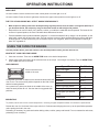 10
10
-
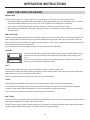 11
11
-
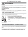 12
12
-
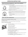 13
13
-
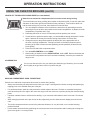 14
14
-
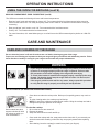 15
15
-
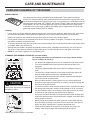 16
16
-
 17
17
-
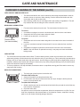 18
18
-
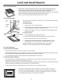 19
19
-
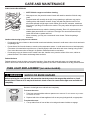 20
20
-
 21
21
-
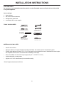 22
22
-
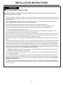 23
23
-
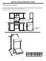 24
24
-
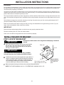 25
25
-
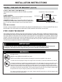 26
26
-
 27
27
-
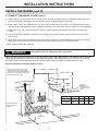 28
28
-
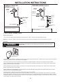 29
29
-
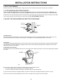 30
30
-
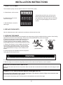 31
31
-
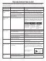 32
32
-
 33
33
-
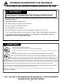 34
34
-
 35
35
-
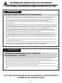 36
36
-
 37
37
-
 38
38
-
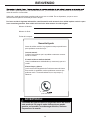 39
39
-
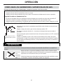 40
40
-
 41
41
-
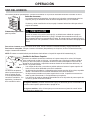 42
42
-
 43
43
-
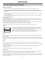 44
44
-
 45
45
-
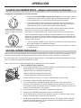 46
46
-
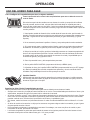 47
47
-
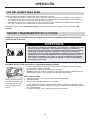 48
48
-
 49
49
-
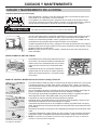 50
50
-
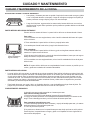 51
51
-
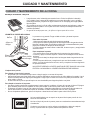 52
52
-
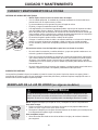 53
53
-
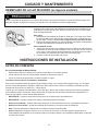 54
54
-
 55
55
-
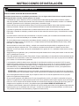 56
56
-
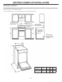 57
57
-
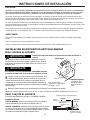 58
58
-
 59
59
-
 60
60
-
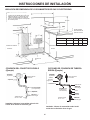 61
61
-
 62
62
-
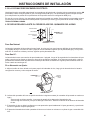 63
63
-
 64
64
-
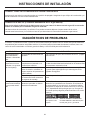 65
65
-
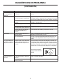 66
66
-
 67
67
-
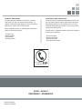 68
68


Danby DR240WGLP El manual del propietario
- Tipo
- El manual del propietario
En otros idiomas
- English: Danby DR240WGLP Owner's manual
Documentos relacionados
-
Danby DR240WGLP El manual del propietario
-
Danby DR241WGLP El manual del propietario
-
Danby DER200W El manual del propietario
-
-
-
-
Danby DR240WGLPC El manual del propietario
-
-
-
Otros documentos
-
Hotpoint RGA824DED1WW El manual del propietario
-
 Kenmore Elite 76033 Guía del usuario
-
Sears Kenmore 71178 El manual del propietario
-
LG Electronics LRG30355SB Manual de usuario
-
-
Kenmore 362.7322 Series El manual del propietario
-
GE Profile PB909SPSS Guía de instalación
