
OWNER’S USE AND CARE GUIDE
GUÍA DE UTILIZACIÓN Y CUIDADO PARA EL PROPIETARIO
MODEL • MODELO
COMPACT ELECTRIC RANGE
ESTUFAS ELECTRICAS COMPACTAS
DER201W / DER240W
24.03.14

TO OBTAIN WARRANTY SERVICE YOU MUST PROVIDE A VALID PROOF OF
PURCHASE. PLEASE STAPLE YOUR RECEIPT TO THIS PAGE FOR FUTURE
REFERENCE.
-------------------------------------------------------------------------------------------------------------------
PARA OBTENER SERVICIO DE GARANTÍA, DEBE PROVEER UN RECIBO
ORIGINAL. POR FAVOR ENGRAPE SU RECIBO A ÉSTA PÁGINA EN CASO QUE
NECESITE HACER UN RECLAMO.
COMPACT ELECTRIC RANGE
Owner’s Use and Care Guide ................................1-25
• Welcome
• Important Safety Information
• Operation Instructions
• Care and Maintenance
• Installation Instructions
• Troubleshooting
• Warranty
ESTUFAS ELECTRICAS COMPACTAS
Guía de utilización y cuidado para el propietario..26-52
• Bienvenido
• Instrucciones de seguridad importantes
• Operación
• Cuidado y mantenimiento
• Instrucciones de instalación
• Diagnósticos de problemas
• Garantía
Model • Modelo
DER201W / DER240W
CAUTION:
Read and follow all safety rules and operating
instructions before fi rst use of this product.
PRECAUCIÓN:
Lea y observe todas las relgas de seguridad y
las instrucciones de operación antes de usar
este producto por la primera vez.
CONTENTS / ÍNDICE

WELCOME
1
Welcome to the Danby family. We’re proud of our quality products, and we believe in dependable service, like you will fi nd
in this Owner’s Use and Care Guide, and like you will receive from our friendly customer service department. Best of all,
you will experience these values each and every time you use your Danby appliance. That’s important, because your new
appliance will be a part of your family for a long time.
Note the information below; you will need this information to obtain service under warranty.
To receive service, you must provide the original receipt.
Model No:
Serial No:
Date Purchased:
NEED HELP?
Before you call for service, here are a few things you can do to
help us serve you better:
Read this Owner’s Use and Care Guide:
It contains instructions to help you use and maintain your
appliance properly.
If you received a damaged appliance:
Immediately contact the retailer (or builder) that sold you the
appliance.
Save time and money:
Check the Troubleshooting section at the end of the guide
before calling. This section helps you solve common problems
that may occur.
If you do need service, you can relax, knowing help is only a
phone call away.
Tel: 1-800-26-
(1-800-263-2629)
WARNING
Read all safety instructions before using the product.
Failure to follow these instructions may result in fi re,
electric shock, serious injury or death.

ANTI-TIP DEVICE
To reduce the risk of tipping the range, the range must be secured by a properly installed anti-tip bracket. See installation
instructions shipped with the bracket for complete details before attempting to install.
For Freestanding Ranges:
To check if the bracket is installed and engaged properly, look underneath the range to see that the anti-tip arm attached
to the side panel is engaged in the bracket. On some models, the storage drawer or kick panel can be removed for easier
inspection. If visual inspection is not possible, slide the range forward, confi rm the anti-tip bracket is securely attached to
the fl oor or wall, and slide the range back so the anti-tip arm slides just under the anti-tip bracket. If the range is pulled
from the wall for any reason, always repeat this procedure to verify the range is properly secured by the anti-tip bracket.
2
IMPORTANT SAFETY INFORMATION
READ ALL INSTRUCTIONS BEFORE USING
WARNING
Tip-Over Hazard
A child or adult can tip the range and be killed. Verify the anti-tip bracket has been
properly installed and engaged to the fl oor or wall. Ensure the anti-tip bracket is re-
engaged when the range is moved by sliding the anti-tip arm just under the bracket.
Do not operate the range without the anti-tip bracket in place and engaged. Failure
to follow these instructions can result in death or serious burns to children or
adults.
Rear wall
Adjacent cabinet or
nal location of right
range side panel
Right side
panel
Rear wall
IMPORTANT SAFETY NOTICE
WARNING
The California Safe Drinking Water and Toxic Enforcement Act requires the Governor of California to publish a
list of substances known to the state to cause cancer, birth defects or other reproductive harm, and requires
businesses to warn customers of potential exposure to such substances.
The fi berglass insulation in self-clean ovens gives off a very small amount of carbon monoxide during the
cleaning cycle. Exposure can be minimized by venting with an open window or using a ventilation fan or hood.
READ AND FOLLOW THIS SAFETY INFORMATION CAREFULLY
SAVE THESE INSTRUCTIONS

IMPORTANT SAFETY INFORMATION
3
READ ALL INSTRUCTIONS BEFORE USING
GENERAL SAFETY INSTRUCTIONS
• Use this appliance for its intended purpose as described in this Owner’s Manual.
• Be sure your appliance is properly installed and grounded by a qualifi ed installer in accordance with the provided
installation instructions.
• Do not attempt to repair or replace any part of your range unless it is specifi cally recommended in this manual. All
other servicing should be referred to a qualifi ed technician.
• Before performing any service, unplug the range or disconnect the power supply at the household distribution panel
by removing the fuse or switching off the circuit breaker.
• Do not leave children alone - children should not be left alone or unattended in an area where an appliance is in use.
They should never be allowed to climb, sit or stand on any part of the appliance.
• CAUTION: Do not store items of interest to children above a range or on the backguard of a range - children
climbing on the range to reach items could be seriously injured.
• Use only dry potholders - moist or damp pot holders on hot surfaces may result in burns from steam. Do not let the
potholders touch hot heating areas. Do not use a towel or other bulky cloth in place of pot holders.
• Never use your appliance for warming or heating the room.
• Do not touch surface elements, areas near the elements or interior surfaces of the oven. These surfaces may be
hot enough to burn even though they are dark in color. During and after use, do not touch, or let clothing or other
fl ammable materials contact the surface elements, areas nearby the surface units or any interior area of the oven;
allow suffi cient time for cooling fi rst. Other surfaces of the appliance may become hot enough to cause burns.
Potentially hot surfaces include the cooktop, areas facing the cooktop, oven vent opening, surfaces near the opening
and crevices around the oven door.
• Do not heat unopened food containers. Pressure could build up and the container could burst, causing an injury.
• Do not use aluminum foil to line drip pans or anywhere in the oven, except as described in this manual. Foil can trap
heat or melt, resulting in damage to the product and a shock or fi re hazard.
• Avoid scratching or impacting glass doors, cook tops or control panels. Doing so may lead to glass breakage. Do not
cook on a product with broken glass. Shock, fi re or cuts may occur.
• Cook meat and poultry thoroughly - meat to at least an internal temperature of 160°F and poultry to at least an internal
temperature of 180°F. Cooking to these temperatures usually protects against foodborne illness.
• Do not store or use fl ammable materials in an oven or near the cooktop, including paper, plastic, pot holders, linens,
wall coverings, curtains, drapes and gasoline or other fl ammable vapors and liquids.
• Never wear loose-fi tting or hanging garments while using the appliance. These garments may ignite if they contact
hot surfaces causing severe burns.
• Do not let cooking grease or other fl ammable materials accumulate in or near the range. Grease in the oven or on the
cooktop may ingnite.
• Clean ventilating hoods frequently. Grease should not be allowed to accumulate on the hood or fi lter.
WARNING
WARNING
KEEP FLAMMABLE MATERIALS AWAY FROM THE RANGE
READ AND FOLLOW THIS SAFETY INFORMATION CAREFULLY
SAVE THESE INSTRUCTIONS

4
IMPORTANT SAFETY INFORMATION
READ ALL INSTRUCTIONS BEFORE USING
• Do not use water on grease fi res. Never pick up a fl aming pan. Turn the controls off. Smother a fl aming pan on a
surface element by covering the pan completely with a well-fi tting lid, cookie sheet or fl at tray. Use a multi-purpose dry
chemical or foam-type fi re extinguisher.
• If there is a fi re in the oven during baking, smother the fi re by closing the oven door and turning the oven off, or by
using a multi-purpose dry chemical or foam-type fi re extinguisher.
• If there is a fi re in the oven during self-clean, turn the oven off and wait for the fi re to go out. Do not force the door
open. Introduction of fresh air at self-clean temperatures may lead to a burst of fl ame from the oven. Failure to follow
this instruction may result in severe burns.
WARNING
IN THE EVENT OF A FIRE, TAKE THE FOLLOWING STEPS
TO PREVENT THE FIRE FROM SPREADING
• Never leave the range unattended while a surface element is ON. Boilovers cause smoking and greasy spillovers that
may catch on fi re.
• Never leave oil unattended while frying. If allowed to heat beyond its smoking point, oil may ignite resulting in fi re that
may spread to surrounding cabinets. Use a deep fat thermometer whenever possible to monitor oil temperature.
• To avoid oil spillover and fi re, use a minimum amount of oil when shallow pan-frying and avoid cooking frozen foods
with excessive amounts of ice.
• Use proper pan size - select cookware having fl at bottoms large enough to cover the surface heating element.
The use of undersized cookware will expose a portion of the element to direct contact and may result in ignition of
clothing. Proper relationship of cookware to surface heating element will also improve effi ciency.
• Only certain types of glass, glass/ceramic, earthenware or other glazed containers are suitable for cooktop service;
others may break because of the sudden change in temperature.
• To minimize the possibility of burns, ignition of fl ammable materials and spillage, the handle of a container should be
turned toward the center of the range without extending over nearby heating elements.
• When preparing fl aming foods under a hood, turn the fan on.
• If power is lost to an electric cooktop while a surface element is ON, the surface element will turn back on as soon as
power is restored. In the event of power loss, failure to turn all surface element knobs to the OFF position may result
in ignition of items on or near the cooktop, leading to serious injury or death.
WARNING
COOKTOP SAFETY INSTRUCTIONS
READ AND FOLLOW THIS SAFETY INFORMATION CAREFULLY
SAVE THESE INSTRUCTIONS

5
READ ALL INSTRUCTIONS BEFORE USING
IMPORTANT SAFETY INFORMATION
• Use care when touching the cooktop. The glass surface of the cooktop will retain heat after the controls have been
turned off.
• Do not cook on a broken cooktop. If glass cooktop should break, cleaning solutions and spillovers may penetrate the
broken cooktop and create a risk of electric shock. Contact a qualifi ed technician immediately.
• Avoid scratching the glass cooktop. The cooktop can be scratched with items such as knives, sharp instruments,
rings or other jewelry, and rivets on clothing.
• Do not place or store items that can melt or catch fi re on the glass cooktop, even when it is not being used. If the
cooktop is inadvertently turned on, they may ignite. Heat from the cooktop or oven vent after it has been turned off
may also cause them to ignite.
• Use a ceramic cooktop cleaner and a
ceramic cooktop cleaning pad to clean the cooktop. Wait until the cooktop cools
and the indicator light goes out before cleaning. A wet sponge or cloth on a hot surface can cause steam burns. Some
cleaners can produce noxious fumes if applied to a hot surface. Note: Sugar spills are an exception. They should be
scraped off while still hot using an oven mitt and a scraper. See the Cleaning the glass cooktop section for detailed
instructions.
• Read and follow all instructions and warnings on the cleaning cream label.
WARNING
RADIANT COOKTOP SAFETY INSTRUCTIONS (Some models)
• Do not immerse or soak the removable surface cooking elements. Do not put them in a dishwasher. Do not self-clean
the surface cooking elements in the oven. Doing so may cause them to fail, resulting in a burn hazard or fi re hazard.
• To avoid the possibility of a burn or an electric shock, always be certain that the controls for all surface elements are
at the OFF position, and that all coils are cool before attempting to lift or remove a coil cooking element.
• Be sure the drip pans are not covered and are in place. Their absence during cooking could damage range parts and
wiring.
• Do not use aluminum foil to line drip pans. Foil can trap heat or melt, resulting in damage to the product and a shock
or fi re hazard.
WARNING
COIL COOKTOP SAFETY INSTRUCTIONS (Some models)
READ AND FOLLOW THIS SAFETY INFORMATION CAREFULLY
SAVE THESE INSTRUCTIONS

6
READ ALL INSTRUCTIONS BEFORE USING
IMPORTANT SAFETY INFORMATION
• Stand away from the range when opening the oven door. Hot air or steam which escapes can cause burns to hands,
face and/or eyes.
• Keep the oven vent unobstructed.
• Keep the oven free from grease build-up. Grease in the oven may ignite.
• Place oven racks in desired location while oven is cool. If rack must be moved while oven is hot, do not let potholder
contact the hot heating element in the oven.
• When using cooking or roasting bags in the oven, follow the manufacturer’s directions.
• Pull the oven rack to the stop-lock position when loading and unloading food from the oven. This helps prevent burns
from touching hot surfaces of the door and oven walls.
• Do not leave items such as paper, cooking utensils or food in the oven when not in use. Items stored in an oven can
ignite.
• Do not use aluminum foil to line the oven bottom. Foil can trap heat or melt, resulting in damage to the product and a
shock hazard or fi re hazard.
WARNING
OVEN SAFETY INSTRUCTIONS
READ AND FOLLOW THIS SAFETY INFORMATION CAREFULLY
SAVE THESE INSTRUCTIONS
• The purpose of the warming drawer is to hold hot cooked foods at serving temperature. Bacteria will grow in food
while it is below 140 °F. Do not put cold food in warming drawer. Do not heat food for more than 2 hours. Failure to
follow these instructions may result in foodborne illness.
• Do not leave paper products, plastics, canned food or combustible materials in the drawer. They may ignite.
• Do not touch the heating element or the interior surface of the drawer. These surfaces may be hot enough to cause
burns.
• Use care when opening the drawer. Open the drawer a crack and let hot air or steam escape before removing or
replacing food. Hot air or steam that escapes can cause burns to hands, face and/ or eyes.
• Do not use aluminum foil to line the lower drawer. The foil will trap heat below, and upset the performance of the oven.
Foil can melt and permanently damage the drawer bottoms.
WARNING
WARMING DRAWER/ LOWER OVEN DRAWER
SAFETY INSTRUCTIONS (Some Models)

OPERATION INSTRUCTIONS
USING THE SURFACE COOKING ELEMENTS
7
Throughout this manual, features and appearance may vary from your model.
SURFACE COOKING CONTROLS
• Your surface elements and controls are designed to give you a variety of heat settings for surface element cooking.
• At both LO and HI positions, there is a slight niche, so the control clicks at those positions. Hi marks the highest
setting; LO marks the lowest setting.
• In a quiet kitchen, you may hear slight clicking sounds during cooking, indicating heat settings selected are being
maintained.
• Switching heats to higher settings always shows a quicker change in temperature than switching to lower settings.
HOW TO SET THE CONTROLS
1. Push the control knob in.
2. Turn either clockwise or counterclockwise to the desired heat setting.
• The control must be pushed in to set only from the OFF position.
• When the control is in any position other than OFF, you can turn it without pushing in.
• Be sure you turn the control to OFF when you fi nish cooking. An indicator light will glow
when ANY surface element is on.
HEAT SETTING GUIDE
• HI - Quick start for cooking; bring water to a boil.
• MEDIUM HIGH - Fast fry, pan broil; maintain a fast boil on a large amount of food.
• MED - Saute and brown; maintain a slow boil on a large amount of food.
• MEDIUM LOW - Cereal; maintain the serving temperature of most foods.
• LO - Cook after starting at HI; cook with little water in in a covered pan. Use to steam rice.
NOTE:
1. At HI or MEDIUM HIGH, never leave food unattended. Boil-overs cause smoking; greasy
spillovers may catch fi re.
2. At LO, melt chocolate, butter on a small element.
COOKING TIPS
• Use medium- or heavyweight cookware. Aluminum cookware conducts heat faster than other metals. Cast-iron and
coated cast-iron cookware is slow to absorb heat, but generally cooks evenly at low or medium heat settings. Steel
pans may cook unevenly if not combined with other metals.
• Do not overfi ll cookware with fat that may spill over when adding food. Frosty foods bubble vigorously. Watch foods
frying at high temperatures. Keep range and hood clean from accumulated grease.
• To conserve the most cooking energy, pans should be fl at on the bottom, have straight sides and tight-fi tting lids.
Match the size of the saucepan to the size of the surface element. A pan that extends more than an inch beyond the
edge of the drip pan, traps heat, which causes “crazing” (fi ne hairline cracks) on porcelain, and discoloration ranging
from blue to dark gray on chrome drip pans.

OPERATION INSTRUCTIONS
USING THE OVEN
The OVEN TEMP knob is located on the control panel on the front of the range.
OVEN TEMPERATURE CONTROLS
• To use the oven, simply turn the knob to the desired cooking temperatures, which are
marked in 25°F increments on the dial. OVEN TEMP maintains the temperature you set,
from 200°F to BROIL.
• The Oven Cycling Light glows until the oven reaches your selected temperature, then
goes off and on with the oven unit(s) during cooking.
OVEN TEMP
OVEN SHELVES
• The shelves are designed with stop-locks so when placed correctly on the shelf supports,
they will stop before coming completely out of the oven and will not tilt when you are
removing food from them or placing food on them.
• When placing cookware on a shelf, pull the shelf out to the bump on the shelf support.
Place the cookware on the shelf, then slide the shelf back into the oven. This will
eliminate reaching into the hot oven.
• To remove the shelves from the oven, pull them toward you, tilt front end upward and
pull them out.
• To replace, place the shelf on the shelf support with stop-locks (curved extension of
shelf) facing up and toward the back of the oven. Tilt up the front and push the shelf
toward the back of the oven until it goes past the bump on the shelf support. Then lower
the front of the shelf and push it all the way back.
OVEN SHELF POSITIONS
• The oven has four shelf supports - A (bottom), B, C, and D (top).
• Shelf positions for cooking are suggested on Baking and Roasting pages.
• Do not use aluminum foil to line oven bottoms. The foil will trap heat below and upset the performance of the oven.
Foil can melt and permanently damage the oven bottom. Damage from improper use of aluminum foil is not covered
by the product warranty.
• Foil may be used to catch spills by placing a sheet on a lower rack, several inches below the food. Do not use more
foil than necessary, and never entirely cover an oven rack this aluminum foil. Keep foil at least 1 1/2” from oven walls
to prevent poor heat circulation.
USE OF ALUMINUM FOIL
8

OPERATION INSTRUCTIONS
USING THE OVEN FOR BAKING OR ROASTING
To avoid possible burns, place the shelves in the desired position before you turn the oven on.
HOW TO SET YOUR OVEN FOR BAKING OR ROASTING
1. Position the shelf or shelves in the oven. If cooking on two shelves at the same time, stagger the pans for best heat
circulation.
2. Close oven door. Turn OVEN TEMP knob clockwise to desired temperature. Preheat oven for at least 10 minutes if
preheating is necessary.
3. Place food in oven on center of shelf. Allow at least 2 inches between edge of bake-ware and oven wall or adjacent
cookware.
4. Check the food to see if it is done at the minimum time on the recipe. Cook longer if necessary. Turn OVEN TEMP
know to OFF and remove the food.
SHELF POSITIONS
• Most baking is done on the second shelf position (B) or the third shelf position (C) from the bottom.
• When baking 3 or 4 items, use two shelves positioned on the second and fourth sets of supports (B & D) from the
bottom of the oven.
• Bake angel food cakes on the fi rst shelf position (A) from the bottom of the oven.
• Roasting is usually done on the bottom shelf position (A).
PREHEATING
• Preheating the oven takes about 10 minutes.
• Preheat the oven only when necessary, usually for baking.
• Most roasts will cook satisfactorily without preheating.
• If you fi nd preheating is necessary, keep an eye on the Oven Cycle light and put food in the oven promptly after the
light goes out. The oven cycle light will then cycle on and off with the oven thermostat as it cycles to maintain the oven
temperature.
• Follow a tested recipe and measure the ingredients carefully. If you are using a package mix, follow label directions.
• Do not open the oven door during a baking operation - heat will be lost and the baking time might need to be
extended. This could cause poor baking results. If you must open the door, open it partially - only 3 or 4 inches - and
close it as quickly as possible.
• Roasting is cooking by dry heat. Tender meat or poultry can be roasted uncovered in your oven. Roasting
temperatures, which should be low and steady, keep spattering to a minimum. When roasting, it is not necessary to
sear, baste, cover, or add water to your meat.
• Frozen roasts of beef, pork, lamb, etc., can be started without thawing, but allow 10 to 25 minutes of additional time
per pound of meat (10 minutes per pound for roasts under 5 pounds, more time for larger roasts).
• Thaw most frozen poultry before roasting to ensure even cooking. Some commercial frozen poultry can be cooked
successfully without thawing. Follow directions given on package label.
BAKING AND ROASTING TIPS
9

OPERATION INSTRUCTIONS
ADJUST THE OVEN THERMOSTAT - EASY TO DO YOURSELF
You may fi nd that your new oven cooks differently than the one it replaced. Use you new oven for a few weeks to
become more familiar with it. If you still think your new oven is too hot or too cold, you can adjust the thermostat
yourself.
Do not use thermometers, such as those found in grocery stores, to check the temperature setting of your oven.
These thermometers may vary 20-40°F.
Note: This adjustment will not affect the broiling temperatures. The adjustment will be retained after a power
failure.
TO ADJUST THE THERMOSTAT WITH THIS TYPE OF KNOB
1. Pull the OVEN TEMP knob off the range and look at the back side. To
make an adjustment, loosen (approximately one turn), but do not completely
remove, the two screws on the back of the knob.
2. With the back of the knob facing you, hold the outer edge of the knob with one
hand and turn the front of the knob with the other hand.
To increase the oven temperature, move the top screw toward the right. You will
hear a click for each notch you move the knob.
To decrease the oven temperature, move the top screw toward the left.
Each click will change the oven temperature approximately 10°F. (The range is plus
or minus 60°F from the arrow.) We suggest that you make the adjustment one click
from the original setting and check oven performance before making any additional
adjustments.)
3. After the adjustment is made, retighten screws so that they are snug, but be
careful not to over-tighten.
4. Replace the knob, matching the fl at area of the knob to the shaft, and check
performance.
THE TYPE OF MARGARINE WILL AFFECT BAKING PERFORMANCE
• Most recipes for baking have been developed using high-fat products such as butter or margarine (80% fat). If
you decrease the fat, the recipe may not give the same results as with a higher fat product.
• Recipe failure can result if cakes, pies, pastries, cookies, or candies are made with low-fat spreads. The lower the fat
content of a spread product, the more noticeable these differences become.
• Federal standards require products labeled “margarine” to contain at least 80% fat by weight. Low-fat spreads, on the
other hand, contain less fat and more water. The high moisture content of these spreads affects the texture and fl avor
of baked goods. For best results with your old favorite recipes, use margarine, butter or stick spreads containing at
least 70% vegetable oil.
L
O
O
S
E
N
S
C
R
E
W
S
T
O
R
O
T
A
T
E
M
A
K
E
C
O
O
L
E
R
M
A
K
E
H
O
T
T
E
R
OVEN TEMP
Front of OVEN TEMP knob
(knob appearance may vary)
Back of OVEN TEMP knob
10

OPERATION INSTRUCTIONS
USING THE OVEN FOR BROILING
Broiling may be slightly different from any previous broiling you may be acquainted with, so be sure to read this
section completely.
HOW TO SET YOUR OVEN FOR BROILING
Broiling is cooking food by intense radiant heat from the upper element in the oven. Most fi sh and tender cuts of meat can
be broiled. Follow these steps to keep spattering and smoking to a minimum.
1. If the meat has fat or gristle around the edge, cut vertical slashes through both about 2” apart. If desired, fat may be
trimmed, leaving a layer about 1/8” thick.
2. Place the meat on a broiler grid in a broiler pan designed for broiling. Always use the grid so the fat drips into the
broiler pan; otherwise the juices may become hot enough to catch fi re.
3. Place the shelf in position C for most broiling.
4. Close the door. Always broil with the door closed.
5. Turn the OVEN TEMP knob clockwise to BROIL. You will feel a slight niche at the broil position.
6. Turn food only once during cooking.
7. Turn the OVEN TEMP knob to OFF. Serve food immediately, and leave the pan outside the oven to cool during the
meal for easiest cleaning.
BROILING GUIDE
• If desired, marinate meats or chicken before broiling, or brush with barbecue sauce the last 5 to 10 minutes only.
• Frozen steaks can be broiled by positioning the oven shelf at the next lowest shelf position and increasing cooking
time given in this guide 1 1/2 times per side.
• When arranging food on pan, do not let fatty edges hang over sides, because the dripping fat wil soil the oven.
• If your range is connected to 208 bolts, rare steaks may be broiled by preheating the broiler and positioning the oven
shelf one position higher.
Food Amount or
Thickness
Shelf
Position
Time in Minutes
First Second
Side Side
Comments
Bacon ½ lb.
(about 8 thin slices)
C 3½ min. 3½ min. Arrange in a single layer.
Ground Beef 1 lb. (4 patties)
½ to ¾” thick
C 10 min. 7 min. Space evenly.
Beef Steaks
(medium)
1” thick
1 to 1½lbs
C 9 min. 9 min. Steaks less than 1” thick cook
through before browning. Pan
frying is recommended. Slash
fat.
Chicken 1 whole
2 to 2½lbs.,
split lengthwise
A 35 min. 15 min. Reduce time about 5 to 10
minutes per side for cut-up
chicken. Brush each side with
melted butter. Broil skin-side-
down fi rst.
Fish 1 lb. fi llets
¼ to ½” thick
C 5 min. 5 min. Handle and turn very care-
fully. Brush with lemon butter
before and during cooking,
if desired. Preheat broiler to
increase browning.
11

CARE AND MAINTENANCE
Be sure electrical power is off and all surfaces are cool before cleaning any part of the range.
Proper care and cleaning are important so that your range will give you effi cient and satisfactory service. Follow
these directions carefully in caring for your range to assure safe and proper maintenance.
WARNING
Tip-Over Hazard
A child or adult can tip the range and be killed. Verify the anti-tip bracket has been
properly installed and engaged to the fl oor or wall. Ensure the anti-tip bracket is re-
engaged when the range is moved by sliding the anti-tip arm just under the bracket.
Do not operate the range without the anti-tip bracket in place and engaged. Failure
to follow these instructions can result in death or serious burns to children or
adults.
SURFACE ELEMENTS AND DRIP PANS
To clean the surface units, turn the control to the highest setting for a minute.
The coils will burn off any soil.
To remove a surface element:
• To remove the drip pans for cleaning, the surface elements must be
removed fi rst. Make sure the surface elements are cool before touching
them.
• Lift the surface element about 1” above the drip pan and pull it out.
• Do not lift the surface element more than 1”. If you do, it may not lie fl at on
the drip pan when you plug it back in.
• NOTE: Repeated lifting of the surface element more than 1 inch above the
drip pan can permanently damage the receptacle.
To replace a surface element:
• Replace the drip pan into the recess in the cooktop. Make sure the opening
in the pan lines up with the receptacle.
• Insert the terminals of the surface element through the opening in the drip
pan and into the receptacle.
• Guide the surface element into place, so it rests evenly.
To clean the drip pans:
• Drip pans can be cleaned in the dishwasher of by hand. If you use a
scouring pad, rub lightly to prevent scratching.
• Q: Can I cover the drip pans with foil?
• A: No, because using foil so close to the receptacle could cause
shock, fi re or damage to the range.
CAUTION:
• Do not immerse the surface elements in liquids of any kind.
• Do not clean the surface units in a dishwasher.
• Do not bend the surface unit plug terminals.
• Do not attempt to clean, adjust or in any way repair the plug-in receptacle.
Drip pan
Receptacle
Surface element
To remove the surface unit, lift it
about 1 inch above the drip pan
and pull it out.
Replace the drip pan into the
recess in the cooktop.
12

Clean the shelves with an abrasive cleanser or steel wool. After cleaning, rinse the
shelves with clean water and dry with a clean cloth.
PORCELAIN ENAMEL COOKTOP
The porcelain enamel fi nish is sturdy, but breakable if misused. This fi nish is acid-resistant. However, any acidic foods
spilled (such as fruit juices, tomato or vinegar) should not be permitted to remain on the fi nish.
OVEN SHELVES
CARE AND MAINTENANCE
LIFT-UP COOKTOP
• Clean the area under the cooktop often. Built-up soil, especially grease,
may catch on fi re.
• To make cleaning easier, the cooktop may be lifted up and propped open.
• Be sure all surface elements are turned off before raising the cooktop.
• Remove the front surface and drip pans. See the Surface Elements and
Drip Pans section. Grasp the two front surface element wells and lift the
cooktop up and prop it open with the prop rod provided.
• After cleaning underneath the cooktop with hot, soapy water and a clean
cloth, hold the cooktop up, return the prop rod to its storage position and
lower the cooktop until it snaps into position. Be careful not to pinch your
fi ngers. Replace the two front drip pans and surface elements. See the
Surface Elements and Dip Pans section.
LIFT-OFF OVEN DOOR
The oven door is removable, but it is heavy. You may need help removing and
replacing the door.
To remove the door:
1. Open the door to the full open position.
2. Pull the hinge locks up over the hinge hooks on both sides.
3. Grasp the door fi rmly on each side, lift slightly and pull it straight out and
away from the oven.
To replace the door:
1. Firmly grasp both sides of the door at the top.
2. Insert and seat the upper and lower hinge arms into the oven slots.
3. Push the hinge locks down from the hinge hooks.
4. Close the oven door and make sure it is working properly. If it is not
working properly, remove and replace it following the above steps.
DO NOT ATTEMPT TO CLOSE THE DOOR UNTIL THIS STEP IS
COMPLETE. THE HINGE OR DOOR COULD BE DAMAGED.
Slot
Hinge
lock
Upper hinge
arm
Lower hinge
arm
13

CARE AND MAINTENANCE
OVEN HEATING ELEMENTS
• Do not clean the bake element or the broil element. Any soil will burn off
when the elements are heated.
• The bake element can be lifted gently to clean the oven fl oor. Do not
attempt to clean any oven surface when any burner element is on. Always
wear protective hand-wear when cleaning interior oven surfaces or
surfaces near heating elements. If spillovers, residue or ash accumulate
around the bake element, gently wipe around the element with warm water.
GLASS WINDOW (on some models)
• To clean the outside glass fi nish, use a glass cleaner. Rinse and polish with a dry cloth. Avoid scratching or impacting
the glass window. Doing so may cause the glass to break.
CONTROL KNOBS
• The control knobs may be removed for easier cleaning.
• Make sure the knobs are in the OFF positions and pull them straight off the stems for cleaning.
• The knobs can be cleaned in a dishwasher or they may also be washed with soap and water. Make sure the insides
of the knobs are dry before replacing.
• Replace the knobs in the OFF position to ensure proper placement.
PAINTED SURFACES
• Painted surfaces include the sides, control panel, door and kick panel. Clean these with soap and water or a vinegar
and water solution.
• Do not use commercial oven cleaners, cleansing powders, steel wool or harsh abrasives on any painted surface.
PORCELAIN OVEN INTERIOR
• With proper care, the porcelain enamel interior will retain its attractive fi nish for many years.
• Soap and water will normally do the job. Heavy spattering or spillovers may require cleaning with a mild abrasive
cleanser. Soapy, wet pads may also be used. Do not allow food spills with a high sugar or acid content (such as
milk, tomatoes, sauerkraut, fruit juices or pie fi lling) to remain on the surface. They may cause dull spots even after
cleaning.
• Household ammonia may make the cleaning job easier. Place 1/2 cup ammonia in a shallow glass pan and leave in a
cold oven overnight. The ammonia fumes will help loosen the burned-on grease and food.
• When necessary, you may use a commercial oven cleaner. Follow the package directions.
Cautions about using spray-on oven cleaners:
• Do not spray the oven cleaner on the electrical controls and switches, because it could cause a short circuit and result
in sparking or fi re.
• Do not directly spray oven cleaner onto the oven heating elements.
14

CARE AND MAINTENANCE
PORCELAIN OVEN INTERIOR (continued)
Cautions about using spray-on oven cleaners:
• Do not allow a fi lm from the cleaner to remain on the temperature sensor - it could cause the oven to heat improperly.
(The sensor is located at the top of the oven.) Carefully wipe the bulb clean after each oven cleaning, being careful
not to move the sensor since a change in its position could affect how the oven bakes.
• Do not spray any oven cleaner on the outside oven door, handles or any exterior surface of the oven, cabinet or
painted surfaces. The cleaner can damage these surfaces.
OVEN LIGHT REPLACEMENT (on some models)
The oven light bulb is covered with a removable glass cover that is held in place
with a bail-shaped wire. Remove the oven door, if desired, to reach the cover easily.
Be sure to let the light cover and bulb cool completely.
To remove the cover:
1. Hold a hand under the cover so it doesn’t fall when released. With the fi ngers of
the same hand, fi rmly push back the wire cover holder. Lift off the cover. Do not
remove any screws to remove the cover.
2. Do not touch the hot bulb with a wet cloth. Replace the bulb with a 40-watt
appliance bulb.
To replace the cover:
1. Place it into the groove of the light receptacle. Pull the wire forward to the
center of the cover, until it snaps into place. When in place, the wire holds the
cover fi rmly. Be certain that the wire is in the depression in the center of the
cover.
2. Connect the electrical power to the range.
WARNING
SHOCK OR BURN HAZARD
Before replacing the oven light bulb, disconnect the electrical power to the range at the main fuse or circuit
breaker panel. Failure to do so may result in electric shock or burn. Be sure to let the light cover and bulb cool
completely.
Wire cover holder
15

INSTALLATION INSTRUCTIONS
16
BEFORE YOU BEGIN
Read these instructions completely and carefully.
IMPORTANT - Save these instructions for the local inspector’s use.
IMPORTANT - Observe all governing codes and ordinances.
Note to Installer - Be sure to leave these instructions with the Consumer.
Note to Consumer - Keep these instructions for future reference.
Skill level - Installation of this appliance requires basic mechanical skills.
Completion time - 1 to 3 hours
Proper installation is the responsibility of the installer.
Product failure due to improper installation is not covered under the Warranty.
WARNING THIS APPLIANCE MUST BE PROPERLY GROUNDED.
Before beginning the installation, switch the power off at the service panel and lock the service disconnecting means to
prevent power from being switched on accidentally. When the service disconnecting means cannot be locked, securely
fasten a prominent warning device, such as a tag, to the service panel.
FOR YOUR SAFETY:
• All rough-in and spacing dimensions must be met for safe use of your range. Electricity to the range can be
disconnected at the outlet without moving the range if the outlet is in the preferred location (remove the lower drawer).
• To reduce the risk of burns or fi re when reaching over hot surface elements, cabinet storage space above the cooktop
should be avoided. If cabinet storage space is to be provided above the cooktop, the risk can be reduced by installing
a range hood that sticks out at least 5” beyond the front of the cabinets. Cabinets installed above a cooktop must be
no deeper than 13”.
• Be sure your appliance is properly installed and grounded by a qualifi ed technician.
• Make sure the cabinets and wall coverings around the range can withstand the temperatures (up to 200°F) generated
by the range.
WARNING
Tip-Over Hazard
• A child or adult can tip the range and be killed.
• Install the anti-tip bracket to the wall or fl oor.
• Engage the range to the anti-tip bracket by sliding the range back so the anti-tip
arm slides under the anti-tip bracket.
• Re-engage the anti-tip bracket if the range is moved.
• Failure to do so can result in death or serious burns to children and adults.
ANTI-TIP DEVICE
WARNING FOR YOUR SAFETY:

INSTALLATION INSTRUCTIONS
PREPARE TO INSTALL THE RANGE
MATERIALS YOU MAY NEED TOOLS YOU WILL NEED
Drill with 1/8” bit Safety Glasses
Adjustable Wrench
Tape Measure
Pliers Pencil
1/4” Nut Driver Level
Phillips Screwdriver Flat-blade Screwdriver
PARTS INCLUDED
Anti-Tip Bracket Kit
(UL Approved 40 AMP)
Squeeze Connector
(For Conduit
Installations Only)
4-Wire Cord
4’ Long
3-Wire Cord
4’ Long
OR
(1) REMOVE SHIPPING MATERIALS
Remove packaging materials. Failure to remove packaging materials could result in damage to the appliance.
(2) PREPARE THE OPENING
• Allow 2” spacing from the range to adjacent vertical walls above the cooktop surface. Allow 30” minimum clearance
between the surface elements and the bottom of unprotected wood or metal top cabinets, and 15” minimum between
the countertop and the adjacent cabinet bottom.
• To eliminate the risk of burns or fi re when reaching over hot surface elements, cabinet storage space above the
cooktop should be avoided. If cabinet storage space is to be provided above the cooktop, the risk can be reduced by
installing a range hood that protrudes at least 5” beyond the front of the cabinets. Cabinets installed above a cooktop
may be no deeper than 13”.
Recommended acceptable electrical outlet area.
Orient the electrical receptacle so the length is
parallel to the floor.
Cord
Floor
Outlet box
Wall
2¼”
Wall Mounted
36” max.
2”
Surface
mount
outlet
36”
5”
2½”
15” min.
From
combustible
walls above
cooking surface
either side
40½”
height
A
C
B
30” min.
13”
max.
D
(Depth
with door
open)
Flooring under the range
• Your range, like many other household
items, is heavy and can settle into soft
fl oor coverings such as cushioned vinyl or
carpeting.
• When moving the range on this type of fl ooring,
it should be installed on a 1/4” thick sheet of
plywood (or similar material) as follows:
• When the fl oor covering ends at the front of the
range, the area that the range will rest on should
be built up with plywood to the same level or
higher than the fl oor covering. This will allow the
range to be moved for cleaning or servicing.
Model A B C D
20” Wide 20” 20 ⅜” 2” 41”
24” Wide 24” 24 ⅜” 2” 41”
17

INSTALLATION INSTRUCTIONS
ELECTRICAL CONNECTIONS
CAUTION
For personal safety, do not use an extension cord with this appliance. Remove house fuse or open circuit breaker
before beginning installation.
• This appliance must be supplied with the proper voltage and frequency, and connected to an individual properly
grounded branch circuit, protected by a circuit breaker or fuse having amperage as specifi ed on the rating plate. The
rating plate is located under the cooktop. See the Lift-Up Cooktop section in this manual for instructions on how to lift
the cooktop.
ELECTRICAL REQUIREMENTS
Rating Plate
• We recommend you have the electrical wiring and hookup
of your range connected by a qualifi ed electrician. After
installation, have the electrician show you where your main
range disconnect is located.
• Check with your local utilities for electrical codes which
apply in your area. Failure to wire your oven according to
governing codes could result in a hazardous condition. If
there are no local codes, your range must be wired and
fused to meet the requirements of the National Electrical
Code, ANSI/ NFPA No. 70 - Latest Edition. You can get a
copy by writing:
• National Fire Protection Association, Batterymarch Park,
Quincy, MA 02269
Effective January 1, 1996, the National Electrical Code requires that new construction (not existing) utilize a
4-conductor connection to an electric range.
When installing an electric range in a new construction, follow Steps 3 and 5 for 4-wire connection.
• You must use a 3-wire, single-phase A.C. 208Y/120 Volt or 240/120 Volt, 60 hertz electrical system. If you connect to
aluminum wiring, properly installed connectors approved for use with aluminum wiring must be used.
• If the electrical service provided does not meet the above specifi cations, have a licensed electrician install an
approved outlet.
• NOTE: Use of automatic, wireless, or wired external switches that shut off power to the appliance is not recommended
for this product.
STOP
ALL NEW BRANCH CIRCUIT INSTALLATIONS, MOBILE HOMES, RECREATIONAL VEHICLES AND
INSTALLATIONS WHERE LOCAL CODES DO NOT ALLOW GROUNDING THROUGH NEUTRAL, REQUIRE A
4-CONDUCTOR CORD OR CONDUIT
• Use only a 3-conductor or a 4-conductor UL-listed range cord. These cords may be provided with ring terminals on
wire and a strain relief device.
• A range cord rated at 40 amps with 125/250 minimum volt range is required. A 50 amp range cord is not
recommended but if used, it should be marked for use with nominal 1 ⅜” diameter connection openings. Care should
be taken to center the cable and strain relief within the knockout hole to keep the edge from damaging the cable.
• Because range terminals are not accessible after the range is in position, a fl exible service conduit or cord must be
used.
• NOTE: If conduit is being used, go to Step 3D and then to Step 6 or 7.
• On some models, a fi lter capacitor may be connected between the black and white leads on the junction block.
18

INSTALLATION INSTRUCTIONS
ELECTRICAL CONNECTIONS (CONT’D)
(3) POWER CORD AND STRAIN RELIEF INSTALLATION
Terminal block
(appearance may vary)
Knockout ring
in bracket
Knockout ring
removed
(A) Remove the wire cover (on the lower back of the range) by
removing its top center screw. Do not discard this screw.
(B) Remove the knockout ring (1 ⅜ ≤) located on the bracket
directly below the terminal block. To remove the knockout,
use a pair of pliers to bend the knockout ring away from the
bracket and twist until the ring is removed.
(C) For power cord installations only (see the next step
D if using a conduit), assemble the strain relief in the hole.
Insert the power cord through the strain relief and tighten.
Allow enough slack to easily attach the cord terminals to the
terminal block. If tabs are present at the end of the winged
strain relief, they can be removed for better fi t.
NOTE: Do not install the power cord without a strain
relief. The strain relief bracket should be installed before
reinstalling the rear range wiring cover.
Skip to Step 4 or 5.
Terminal
block
Bracket
Power cord
Strain relief
Terminal
block
Bracket
Squeeze
connector
Conduit
(D) For conduit installations only, purchase a squeeze
connector matching the diameter of your conduit and
assemble it in the hole. Insert the conduit through the
squeeze connector and tighten. Allow enough slack to
easily attach the wires to the terminal block.
NOTE: Do not install the conduit without a squeeze
connector. The squeeze connector should be installed
before reinstalling the rear range wiring cover.
Skip to Step 6 or 7.
19

INSTALLATION INSTRUCTIONS
4) 3-WIRE POWER CORD INSTALLATION
WARNING
The neutral or ground wire of the power cord
must be connected to the neutral terminal
located in the center of the terminal block.
The power leads must be connected to the
lower left and the lower right terminals of the
terminal block.
(A) Remove the 3 lower terminal screws from
the terminal block. Insert the 3 terminal screws
through each power cord terminal ring and into
the lower terminals of the terminal block. Be
certain that the center wire (white/neutral) is
connected to the center lower position of the
terminal block. Tighten screws securely into the
terminal block. DO NOT remover the ground
strap connection.
(B) Skip to Step 8 and proceed with the
installation.
The neutral wire of the supply circuit must
be connected to the neutral terminal located
in the lower center of the terminal block.
The power leads must be connected to the
lower left and the lower right terminals of the
terminal block. The 4th grounding lead must
be connected to the frame of the range with
the ground plate and the ground screw.
(A) Remove the 3 lower terminal screws from the
terminal block. Remover the ground screw and
ground plate and retain them.
(B) Cut and discard the ground strap. DO NOT
DISCARD ANY SCREWS.
(C) Insert the one ground screw into the power
cord ground wire terminal ring, through the
ground plate and into the frame of the range.
(D) Insert the 3 terminal screws (removed earlier)
through each power cord terminal ring and into
the lower terminals of the terminal block. Be
certain that the center wire (white/neutral) is
connected to the center lower position of the
terminal block. Tighten the screws securely into
the terminal block.
(E) Skip to Step 8 and proceed with the
installation.
5) 4-WIRE POWER CORD INSTALLATION
WARNING
Terminal block
(appearance may
vary)
Neutral
terminal
Ground
strap
Ground
plate
Power cord
Before
After
Ground strap
Terminal
block
Neutral
terminal
Cut and discard
the ground strap
Neutral
terminal
Ground plate
(grounding
to range)
Ground
screw
Terminal
block
or
20

INSTALLATION INSTRUCTIONS
ELECTRICAL CONNECTIONS (CONT’D)
(6) 3-WIRE CONDUIT INSTALLATION
(A) Loosen the 3 lower terminal screws from the terminal
block. Insert the center bare wire (white/neutral) tip through
the bottom center terminal block opening. On certain models,
the wire will need to be inserted through the ground strap
opening and then into the bottom center block opening.
Insert the two side bare wire tips into the lower left and lower
right terminal block openings. Tighten the screws until the
wire is fi rmly secure (approximately 20 inch-lbs.).
NOTE: ALUMINUM WIRING
Aluminum building wire may be used, but it must be rated
for the correct amperage and voltage to make connection.
Connect wires according to this Step 6 or Step 7 depending
on the number of wire.
Wire used, location and enclosure of splices, etc., must
conform to good wiring practices and local codes.
(B) Skip to Step 8 and proceed with the installation.
(7) 4-WIRE CONDUIT INSTALLATION
(A) Loosen the three lower terminal screws from the terminal
block. Remove the ground screw and ground plae and
retain them. Cut and discard the ground strap. DO NOT
DISCARD ANY SCREWS.
(B) Insert the ground bare wire tip between the range frame
and ground plate (removed earlier) and secure it in place
with the ground screw (removed earlier) and secure it in
place with the ground screw (removed earlier). Insert the
bare wire (white/neutral) tip through the bottom center of
the terminal block opening. Insert the two side bare wire
tips into the lower left and the lower right terminal block
openings. Tighten the screws until the wire is fi rmly secure
(approximately 20 inch-lbs.).
Wire used, location and enclosure of splices, etc., must
conform to good wiring practices and local codes.
(C) Proceed to Step 8.
(8) REPLACE THE WIRE COVER
Replace the wire cover on the range back by sliding its
two lower retaining tabs into the slots and replacing the
screw removed earlier. Make sure that no wires are pinched
between the cover and the range back.
Terminal
block
Wire tips
Bracket
Conduit
Before
After
Terminal
block
Cut and discard
the ground strap
Neutral terminal
Ground strap
Terminal
block
Wire tips
Ground
screw
Ground plate
(grounding
to range)
Bracket
21

INSTALLATION INSTRUCTIONS
INSTALL THE RANGE
(9) ANTI-TIP DEVICE INSTALLATION
WARNING
Tip-Over Hazard
• A child or adult can tip the range and be killed.
• Install the anti-tip bracket to the wall or fl oor.
• Engage the range to the anti-tip bracket by sliding the range back so the anti-tip
arm slides under the anti-tip bracket.
• Re-engage the anti-tip bracket if the range is moved.
• Failure to do so can result in death or serious burns to children or adults.
To reduce the RISK OF TIPPING the range, the range must be secured by a properly installed ANTI-TIP BRACKET.
Secure the bracket with the screws provided. See installation instructions for complete details before attempting to install.
NOTE: The installation of the ANTI-TIP bracket must meet all local codes for securing the appliance.
STEP 1 LOCATE THE BRACKET
IMPORTANT:
Determine the fi nal location of the range before attempting to install the
bracket.
Place the bracket on the fl oor with the back edge against
the rear wall. If the range does not reach the rear wall,
align the back edge of the bracket with the rear panel of
the range in its fi nal location.
Rear Wall
Adjacent cabinet or
nal location of right
range side panel
Loc. A
Loc. B
Two screws must enter oor
or wall at Loc. A or B.
IMPORTANT:
If the bracket does not touch the rear wall, you MUST
screw the bracket to the FLOOR as described in Step 2.
Position the side of the bracket against the right cabinet. If
there is no adjacent cabinet, align the edge of the bracket
with the right side panel of the range in its fi nal location. If
the countertop overhangs the cabinet, offset the bracket
from the cabinet by the amount of the overhang.
A
B
Mark the location for the pair of holes to be used (see illustration above).
NOTE: For FLOOR installation use Loc. A. For REAR WALL installation use Loc. B.
C
STEP 2 SECURE THE BRACKET
Screw must
enter wood
or concrete
Attachment to Floor or Rear Wall
Wall sill plate
Screw must enter wood
Bracket
Anti-tip
arm
The bracket must be screwed to either the FLOOR or the REAR
WALL.
FLOOR Installation
WOOD FLOOR: Use the screws provided to secure the bracket
using the pair of marked holes (Loc. A).
CONCRETE FLOOR: Using a concrete bit, drill a 5/32” pilot hole
2” deep into the concrete at the center of each of the marked holes
(Loc. A). Use the screws provided to secure the bracket into the
fl oor.
22
REAR WALL Installation
Use the 2 screws provided to secure the bracket using the pair of marked holes at Loc. B. The screws MUST enter into a
wood sill plate. If the wall contains any metal studs or similar materials, then the fl oor must be used.

• Check to make sure the circuit breaker is closed (RESET) or the circuit fuses are replaced.
• Be sure power is in service to the building.
• Check to be sure that all packing materials and tape have been removed. This will include tape on the metal panel
under control knobs (if applicable), adhesive tape, wire ties, cardboard and protective plastic. Failure to remove these
materials could result in damage to the appliance once the appliance has been turned on and surfaces have heated.
• Check that the door and drawer are parallel to each other and that both operate smoothly. If they do not, see the
Owner’s Manual for proper replacement.
• Check to make sure that the Anti-Tip device is securely installed.
• Be sure all range controls are in the OFF positions before leaving the range.
(10) LEVEL THE RANGE
For proper cooking and baking, the range must be
leveled. Leveling legs are located on each corner at
the base of the range.
(A) Install the oven shelves (see Using the oven
section for instructions). Put a spirit level or a glass
measuring cup partially fi lled with water on one of the
oven shelves. If using a spirit level, take two readings
- with the level placed diagonally, fi rst in one direction
and then the other.
(B) Turn the legs clockwise to raise the range and
counterclockwise to lower the range. Adjust the
leveling legs until the range is level.
(11) FINAL INSTALLATION CHECKLIST
INSTALLATION INSTRUCTIONS
INSTALL THE RANGE
(9) ANTI-TIP DEVICE INSTALLATION (cont’d)
STEP 3 CHECK THE BRACKET
After installing the bracket, slide the range into its fi nal location. To check if the bracket is installed and engaged properly,
look underneath the range to see that the anti-tip arm attached to side panel is engaged in the bracket. On some models,
the storage drawer or kick panel can be removed for easier inspection. If visual inspection is not possible, slide the range
forward, confi rm the anti-tip bracket is securely attached to the fl oor or wall, and slide the range back so the anti-tip arm
slides just under the anti-tip bracket. If the range is pulled from the wall for any reason, always repeat this procedure to
verify the range is properly secured by the anti-tip bracket.
IMPORTANT:
The anti-tip bracket must be PROPERLY INSTALLED to prevent the range from tipping. NEVER remove the
leveling legs. This will prevent the range from being secured to the ANTI-TIP bracket properly.
23

Occasionally, a problem is minor and a service call may not be necessary- use this troubleshooting guide for a possible
solution. If the unit continues to operate improperly, call an authorized service depot or Danby’s Toll Free Number 1-800-
263-2629 for assistance.
TROUBLESHOOTING GUIDE
PROBLEM POSSIBLE CAUSE SOLUTION
Surface elements not
functioning properly.
The surface elements are not
plugged in solidly.
With the controls off, check to make sure that the
surface element is plugged completely into the
receptacle.
The surface element controls are
improperly set.
Check to see that the correct control is set for the
surface element you are using.
The drip pans are not set securely in
the cooktop.
With the controls off, check to make sure the drip
pan is in the recess in the cooktop and that the
opening in the pan lines up with the receptacle.
Oven will not work. A fuse in your home may be blown or
the circuit breaker tripped.
Replace the fuse or reset the circuit breaker.
Plug on range is not completely
inserted in the electrical outlet.
Make sure that the electrical plug is plugged into a
live, properly grounded outlet.
Oven control is improperly set. See the Using the oven sections.
Food does not broil
properly.
Oven control is improperly set. Make sure you turn the knob all the way to the
BROIL position.
Improper shelf position is being used. See the Broiling Guide.
Cookware is not suited for broiling. Use the broiling pan and grid that came with your
range.
Aluminum foil used on the broiling
pan and grid has not been fi tted
properly and slit as recommended.
See the Use of aluminum foil section.
Food does not bake or
roast properly.
Oven control is improperly set. See the Using the oven for baking or roasting sec-
tion.
Shelf position is incorrect or the shelf
is not level.
See the Using the oven for baking or roasting sec-
tion.
Necessary preheating was not done. See the Using the oven for baking or roasting sec-
tion.
Incorrect cookware or cookware of
improper size is being used.
See the Using the oven for baking or roasting sec-
tion.
Oven light does not
work.
Light bulb is loose. Tighten or replace the bulb.
Switch which operates the light is
broken.
Call for service.
24

LIMITED IN-HOME APPLIANCE WARRANTY
This quality product is warranted to be free from manufacturer’s defects in material and workmanship, provided that the unit is used under the normal operating
conditions intended by the manufacturer.
This warranty is available only to the person to whom the unit was originally sold by Danby Products Limited (Canada) or Danby Products Inc. (U.S.A.) (hereafter
“Danby”) or by an authorized distributor of Danby, and is non-transferable.
TERMS OF WARRANTY
Plastic parts, are warranted for thirty (30) days only from purchase date, with no extensions provided.
First Year
During the rst twelve (12) months, any functional parts of this product found to be defective, will be repaired or replaced, at warrantor’s
option, at no charge to the ORIGINAL purchaser.
To obtain
Danby reserves the right to limit the boundaries of “In Home Service” to the proximity of an Authorized Service Depot. Any app liance
Service
requiring service outside the limited boundaries of “In Home Service” , it will be the consumer’s responsibility to transport the appliance (at
their own expense) to the original retailer (point of purchase) or a service depot for repair. See “Boundaries of In Home Serv ice” below.
Contact your dealer from whom your unit was purchased, or contact your nearest authorized Danby service depot, where service
must be performed by a qualied service technician.
If service is performed on the units by anyone other than an authorized service depot, or the unit is used for commercial appli cation, all
obligations of Danby under this warranty shall be void.
Boundaries of
If the appliance is installed in a location that is 100 kilometers (62 miles) or more from the nearest service center your unit must be
In Home Service
delivered to the nearest authorized Danby Service Depot, as service must only be performed by a technician qualied and certif ied for
warranty service by Danby. Transportation charges to and from the service location are not protected by this warranty and are t he
responsibility of the purchaser.
Nothing within this warranty shall imply that Danby will be responsible or liable for any spoilage or damage to food or other c ontents of this appliance, whether due
to any defect of the appliance, or its use, whether proper or improper.
EXCLUSIONS
Save as herein provided, Danby, there are no other warranties, conditions, representations or guarantees, express or implied, m ade or intended by Danby or its
authorized distributors and all other warranties, conditions, representations or guarantees, including any warranties, conditio ns, representations or guarantees
under any Sale of Goods Act or like legislation or statue is hereby expressly excluded. Save as herein provided, Danby shall no t be responsible for any damages
to persons or property, including the unit itself, howsoever caused or any consequential damages arising from the malfunction o f the unit and by the purchase of
the unit, the purchaser does hereby agree to indemnify and hold harmless Danby from any claim for damages to persons or propert y caused by the unit.
GENERAL PROVISIONS
No warranty or insurance herein contained or set out shall apply when damage or repair is caused by any of the following:
1) Power failure.
2) Damage in transit or when moving the appliance.
3) Improper power supply such as low voltage, defective house wiring or inadequate fuses.
4) Accident, alteration, abuse or misuse of the appliance such as inadequate air circulation in the room or abnormal operating con ditions
(extremely high or low room temperature).
5) Use for commercial or industrial purposes (ie. If the appliance is not installed in a domestic residence).
6) Fire, water damage, theft, war, riot, hostility, acts of God such as hurricanes, oods etc.
7) Service calls resulting in customer education.
8) Improper Installation (ie. Building-in of a free standing appliance or using an appliance outdoors that is not approved for out door application).
Proof of purchase date will be required for warranty claims; so, please retain bills of sale. In the event warranty service is required, present this document to our
AUTHORIZED SERVICE DEPOT.
Danby Products Limited
PO Box 1778, Guelph, Ontario, Canada N1H 6Z9
Telephone: (519) 837-0920 FAX: (519) 837-0449
Danby Products Inc.
PO Box 669, Findlay, Ohio, U.S.A. 45840
Telephone: (419) 425-8627 FAX: (419) 425-8629
04/09
1-800-263-2629
Warranty Service
In-home
If the appliance is installed in a location that is 100 kilometers (62 miles) or more from the nearest
service center your unit must be delivered to the nearest authorized Danby Service Depot, as service
must only be performed by a technician qualified and certified for warranty service by Danby. Transpor-
tation charges to and from the service location are not protected by this warranty and are the responsi-
bility of the purchaser.
During the first eighteen (18) months, any functional parts of this product found to be defective, will be
repaired or replaced, at warrantor’s option, at no charge to the ORIGINAL purchaser.
Danby reserves the right to limit the boundaries of “In Home Service” to the proximity of an Authorized
Service Depot. Any appliance requiring service outside the limited boundaries of “In Home Service”, it
will be the consumer’s responsibility to transport the appliance (at their own expense) to the original
retailer (point of purchase) or a service depot for repair. See “Boundaries of In Home Service” below.
Contact your dealer from whom your unit was purchased, or contact your nearest authorized Danby
service depot, where service must be performed by a qualified service technician. If service is performed
on the unit by anyone other than an authorized service depot, or the unit is used for commercial
application, all obligations of Danby under this warranty shall be void.
First 18 months
To obtain
service
Boundaries of
In Home Service
LIMITED IN-HOME APPLIANCE WARRANTY
This quality product is warranted to be free from manufacturer’s defects in material and workmanship, provided that the unit is
used under the normal operating conditions intended by the manufacturer.
This warranty is available only to the person to whom the unit was originally sold by Danby Products Limited (Canada) or
Danby Products Inc. (U.S.A.) (hereafter “Danby”) or by an authorized distributor of Danby, and is non-transferable.
TERMS OF WARRANTY
Plastic parts, are warranted for thirty (30) days only from purchase date, with no extensions provided.
Nothing within this warranty shall imply that Danby will be responsible or liable for any spoilage or damage to food or other
contents of this appliance, whether due to any defect of the appliance, or its use, whether proper or improper.
EXCLUSIONS
Save as herein provided, by Danby, there are no other warranties, conditions, representations or guarantees, express or
implied, made or intended by Danby or its authorized distributors and all other warranties, conditions, representations or
guarantees, including any warranties, conditions, representations or guarantees under any Sale of Goods Act or like legislation
or statute is hereby expressly excluded. Save as herein provided, Danby shall not be responsible for any damages to persons
or property, including the unit itself, howsoever caused or any consequential damages arising from the malfunction of the unit
and by the purchase of the unit, the purchaser does hereby agree to indemnify and hold harmless Danby from any claim for
damages to persons or property caused by the unit.
GENERAL PROVISIONS
No warranty or insurance herein contained or set out shall apply when damage or repair is caused by any of the following:
1) Power failure.
2) Damage in transit or when moving the appliance.
3) Improper power supply such as low voltage, defective house wiring or inadequate fuses.
4) Accident, alteration, abuse or misuse of the appliance such as inadequate air circulation in the room or abnormal operating
conditions (extremely high or low room temperature).
5) Use for commercial or industrial purposes (ie. If the appliance is not installed in a domestic residence).
6) Fire, water damage, theft, war, riot, hostility, acts of God such as hurricanes, floods etc.
7) Service calls resulting in customer education.
8) Improper Installation (ie. Building-in of a free standing appliance or using an appliance outdoors that is not approved for
outdoor application).
Proof of purchase date will be required for warranty claims; so, please retain bills of sale. In the event warranty service is
required, present this document to our AUTHORIZED SERVICE DEPOT.
Warranty Service
In-home
Danby Products Limited
PO Box 1778, Guelph, Ontario, Canada N1H 6Z9
Telephone: (519) 837-0920 FAX: (519) 837-0449
Danby Products Inc.
PO Box 669, Findlay, Ohio, U.S.A. 45840
Telephone: (419) 425-8627 FAX: (419) 425-8629
1-800-263-2629
07/13

BIENVENIDO
-
able. Usted lo podrá apreciar en este manual fácil de usar, y lo escuchará en las voces amistosas de nuestro departa
mento de servicio al consumidor.
Sobre todo, usted apreciará estas ventajas cada vez que use su unidad. Eso es importante, ya que su nuevo
artefacto formará parte de su familia por mucho tiempo.
Por favor escriba la siguiente información; esta información será necesaria si su unidad requiere servicio o para
hacer consultas generales. Para recibir servicio técnico debe mostrar el recibo original.
Número de modelo:
Número de serie:
Fecha de la compra:
Necesita Ayuda
Antes de solicitar servicio, hay algunas cosas que puede hacer
para ayudarnos a servirle mejor…
Lea este manual:
Contiene instrucciones que lo ayudarán a mantener correcta-
mente su unidad.
Si usted recibe un artefacto dañado:
Llame inmediatamente al distribuidor (o constructor) que se lo
vendió.
Ahorre tiempo y dinero:
Lea la sección de Diagnóstico de Problemas antes de llamar.
Esta sección le ayudará a resolver problemas comunes que
pudieran ocurrir. Si necesita asistencia, no se preocupe y
llámenos.
T
el: 1-800-26-
(1-800-263-2629)
26
ADVERTENCIA:
Lea todas las instrucciones de seguridad antes de utilizar
este producto. No seguir estas instrucciones puede
generar un incendio, una descarga eléctrica, lesiones
corporales o la muerte.

27
INFORMACIÓN IMPORTANTE DE SEGURIDAD
LEA TODAS LAS INSTRUCCIONES ANTES DE SU USO
DISPOSITIVO ANTI-VOLCADURAS
ADVERTENCIA
Riesgo de Volcaduras
Un niño o adulto pueden volcar la cocina y morir. Verifi que que el soporte anti-
volcaduras se haya instalado y ajustado correctamente al piso o la pared.
Asegúrese de que el soporte anti-volcaduras sea reajustado cuando mueva la estufa
deslizando el brazo anti-volcaduras justo debajo del soporte. No utilice la cocina
sin que el soporte anti-volcaduras esté colocado y ajustado. Si estas instrucciones
no se siguen, como resultado se podrá producir la muerte o quemaduras graves de
niños y adultos.
Para reducir el riesgo de volcar la cocina, ésta debe sujetarse mediante un soporte anti-volcaduras con una adecuada
instalación. Ver las instrucciones de instalación enviadas con el soporte para obtener detalles completos antes de iniciar
la instalación.
Para cocinas independientes:
Para revisar si el soporte está instalado y ajustado de forma apropiada, mire que debajo de la cocina, el brazo anti
volteo ensamblado en el lateral, este ajustado al soporte. En algunos modelos, el cajón de almacenamiento o el panel
de protección se puede retirar para una inspección más fácil. Si no es posible realizar una inspección visual, deslice la
cocina hacia adelante, confi rme que el soporte anti-volcaduras esté ajustado de forma segura al piso o la pared, y deslice
la cocina hacia atrás de modo que el brazo anti volteo se deslice por debajo del soporte anti-volcaduras.
Si la cocina es expulsada de la pared por alguna razón, siempre repita este procedimiento a fi n de verifi car que esté
asegurada de forma correcta con un soporte anti volcaduras.
Pared trasera
Gabinete adyacente
o ubicación nal del
panel lateral derecho
de la cocina
Panel lateral
derecho
Pared trasera
NOTIFICACIÓN IMPORTANTE DE SEGURIDAD
ADVERTENCIA
La ley de California sobre aguas potables y tóxicos exige que el Gobernador de California publique una lista de
sustancias que según el estado provoquen cáncer, defectos congénitos u otros daños reproductivos, y exige a
las empresas que adviertan a los clientes sobre la exposición potencial a dichas sustancias.
La aislación de fi bra de vidrio de los hornos auto-limpiantes emite una pequeña cantidad de monóxido de
carbono durante el ciclo de limpieza. La exposición puede minimizarse ventilando con una ventana abierta o
usando une campana o ventilador.
LEA Y SIGA ESTA INFORMACIÓN DE SEGURIDAD CUIDADOSAMENTE
GUARDE ESTAS INSTRUCCIONES

INFORMACIÓN IMPORTANTE DE SEGURIDAD
28
LEA TODAS LAS INSTRUCCIONES ANTES DE SU USO
• Use este aparato sólo con el objetivo para el que fue creado, como se describe en este Manual del Propietario.
• Asegúrese de que un técnico califi cado realice una correcta instalación y puesta a tierra del artefacto de acuerdo con
las instrucciones de instalación provistas.
• No intente reparar o cambiar ninguna pieza de su cocina a menos que esté específi camente recomendado en este
manual. Cualquier otro servicio debe realizarlo un técnico califi cado.
• Antes de realizar cualquier clase de reparación, desenchufe la cocina o desconecte el suministro eléctrico desde el
panel de distribución doméstico quitando el fusible o desconectando el interruptor de circuitos.
• No deje a los niños solos; éstos no deben quedar solos o sin atención en un área donde un aparato esté en uso.
Nunca debe permitirse que se suban, sienten o paren en cualquier parte de este aparato.
• PRECAUCION: No almacene elementos de interés para niños sobre una cocina o en la protección trasera de una
cocina: los niños que se trepan a la cocina para alcanzar elementos pueden resultar gravemente heridos.
• Sólo use agarraderas secas: las agarraderas húmedas o mojadas colocadas en superfi cies calientes pueden
provocar quemaduras de vapor. Tenga cuidado de no tocar los calentadores con las agarradores. No utilice toallas u
otras telas gruesas en lugar de una agarradera.
• Nunca use su electrodoméstico para calentar la habitación.
• No toque las placas de cocción, las zonas próximas a éstas ni los calentadores y las superfi cies interiores del
horno. Estas superfi cies pueden estar lo sufi cientemente calientes para quemar aún cuando tengan un color oscuro.
Durante y después del uso, no toque o deje que su vestimenta u otros materiales infl amables entren en contacto
con las placas de cocción, áreas cercanas a las placas de cocción o cualquier área interior del horno; deje pasar
un tiempo prudencial para que se enfríen. Otras superfi cies del aparato pueden calentarse lo sufi ciente como para
provocar quemaduras. Las superfi cies potencialmente calientes incluyen la estufa, las áreas orientadas hacia
la estufa, la abertura de ventilación del horno, las superfi cies cercanas a la abertura y las hendiduras ubicadas
alrededor de la puerta del horno.
• No caliente recipientes cerrados de alimentos. Podría haber una acumulación de presión en el recipiente y éste
podría explotar, provocando lesiones.
• No utilice papel de aluminio para revestir las bandejas colectoras o ninguna parte del horno, con excepción de lo
descripto en este manual. Un uso inadequado puede provocar daños a la cocina y una descarga eléctrica o un riesgo
de incendio.
• Trate de no rayar o golpear las puertas, estufas o paneles de control de vidrio. Si lo hace podría romperse el vidrio.
No cocine si un producto tiene un vidrio roto. Puede provocarse une descarga, un incendio o heridas.
• Cocine carnes de res y de ave por completo: Las carnes de res hasta alcanzar una temperatura interna de por lo
menos 160°F (71°C) y las carnes de ave a una temperatura interna de por lo menos 180°F (82°C). La cocción a
estas temperaturas generalmente protege de enfermedades trasmitidas por los alimentos.
INSTRUCCIONES GENERALES DE SEGURIDAD
ADVERTENCIA
LEA Y SIGA ESTA INFORMACIÓN DE SEGURIDAD CUIDADOSAMENTE
GUARDE ESTAS INSTRUCCIONES

29
LEA TODAS LAS INSTRUCCIONES ANTES DE SU USO
INFORMACIÓN IMPORTANTE DE SEGURIDAD
• No almacene o utilice materiales infl amables dentro de un horno o cerca de la estufa, tales como papel, plástico,
agarraderas, telas, recubrimientos de pared, cortinas y gasolina u otros vapores y líquidos infl amables.
• Nunca use vestimentas holgadas o amplias mientras utilice el aparato. Estas vestimentas pueden prenderse fuego si
entran en contacto con superfi cies calientes, provocando quemaduras graves.
• No permita que la grasa de la cocción u otros materiales infl amables se acumulen dentro de la cocina o en su
cercanía. La grasa dentro del horno o sobre la estufa puede encenderse.
• Limpie las campanas de ventilación con frecuencia. No debe permitirse la acumulación de grasa en la campana o en
el fi ltro.
MANTENGA LOS MATERIALES INFLAMABLES
ALEJADOS DE LA COCINA
ADVERTENCIA
• No utilice agua en incendios de grasa. Nunca levante une sartén en llamas. Apague los controles. Apague una
sartén en llamas sobre una placa de cocción cubriendo la sartén por completo con una tapa que ajuste bien, una
plancha para galletas o una bandeja plana. Utilice un extintor de incendios multiuso de químico seco o un extintor de
incendios de espuma.
• Si hay un incendio en el horno durante el horneado, apáguelo cerrando la puerta del horno y apagando el control o
usando un extintor de incendios multiuso de químico seco o un extintor de incendios de espuma.
• Si hay un incendio en el horno durante la auto-limpieza, apague el horno y espere a que el incendio se consuma. No
abra la puerta del horno a la fuerza. El ingreso de aire fresco a temperaturas de auto-limpieza puede provocar una
explosión de llamas desde el horno. No seguir esta instrucción puede provocar quemaduras graves.
EN CASO DE INCENDIO, SIGA LOS SIGUIENTES PASOS
PARA EVITAR LA PROPAGACIÓN DEL FUEGO
ADVERTENCIA
• Nunca deje la cocina sin atención mientras una placa de cocción esta en ON (Encendida). Los alimentos que hierven
y se derraman pueden provocar humo y derrames grasosos que pueden prenderse fuego.
• Nunca deje aceite sin atención mientras fríe. Si se deja calentar más allá del punto de humeo, el aceite puede
encenderse, provocando un incendio que podría propagarse a los gabinetes cercanos. Utilice un termómetro para
grasa cuando sea posible para controlar la temperatura del aceite.
• Para evitar el derrame de aceite y un incendio, utilice una cantidad mínima de aceite cuando fría en sartenes poco
profundas y evite la cocción de alimentos congelados con una cantidad excesiva de hielo.
• Utilice el tamaño de recipiente adecuado: Elija recipientes con bases planas lo sufi cientemente grandes para cubrir
el elemento calentador de superfi cie. La utilización de recipientes más pequeños dejará expuesta una porción de la
placa de cocción al contacto directo, lo que puede provocar el encendido de sus vestimentas. Una relación adecuada
del recipiente con la placa de cocción también mejorará la efi ciencia.
• Sólo ciertos tipos de recipientes de vidrio, vidrio/cerámico, cerámica, u otros recipientes vidriados pueden utilizarse
sobre la estufa; otros pueden romperse debido al cambio repentino de temperatura.
• Para minimizar la posibilidad de quemaduras, el encendido de materiales infl amables y los derrames, la manija de los
recipientes deben girarse hacia el centro de la cocina sin extenderse sobre ninguna placa de cocción cercana.
INSTRUCCIONES DE SEGURIDAD DE LA ESTUFA
ADVERTENCIA
LEA Y SIGA ESTA INFORMACIÓN DE SEGURIDAD CUIDADOSAMENTE
GUARDE ESTAS INSTRUCCIONES

30
LEA TODAS LAS INSTRUCCIONES ANTES DE SU USO
INFORMACIÓN IMPORTANTE DE SEGURIDAD
• Si fl ambea alimentos bajo la campana, encienda el ventilador.
• Si se corta la corriente de una estufa eléctrica mientras una placa de cocción está en ON (Encendida), la unidad de
superfi cie volverá a ON (Encendida) tan pronto como se recupere la electricidad. En caso de pérdida de corriente, no
colocar las perillas de placas de cocción en OFF (Apagado) podrá producir el incendio de los artículos que estén en o
cerca de la estufa, y ocasionar lesiones graves o la muerte.
INSTRUCCIONES DE SEGURIDAD DE LA ESTUFA
ADVERTENCIA
• Tenga cuidado al tocar la estufa. La superfi cie de vidrio de la estufa retendrá calor después de que los controles se
hayan apagado.
• No cocine sobre una estufa rota. Si la estufa se rompe, las soluciones de limpieza y los derrames pueden penetrar en
la estufa rota y crear un riesgo de descarga eléctrica. Comuníquese con un técnico califi cado de inmediato.
• Evite rayar la estufa de vidrio. La estufa puede rayarse con elementos tales como cuchillos, instrumentos fi losos,
anillos u otras joyas, y remaches de la ropa.
• No coloque o almacene elementos que pueden derretirse o prenderse fuego sobre la estufa de vidrio, aún cuando
no la esté usando. Si la estufa se enciende en forma accidental, pueden prenderse fuego. El calor proveniente de la
estufa o de la ventilación del horno también puede prenderlos fuego, aún si el aparato está apagado.
• Use un limpiador de estufas cerámicas
y una esponjilla de limpieza de estufas cerámicas
para limpiar la estufa.
Espere hasta que la estufa se enfríe y la luz indicadora se apague antes de limpiar. Una esponja o un paño húmedos
sobre un superfi cie caliente pueden producir humos tóxicos si se los aplica a una superfi cie caliente. NOTA: Los
derrames de azúcar son la excepción. Éstos deben quitarse mientras están calientes utilizando una agarradera y un
raspador. Para instrucciones detalladas, ver la sección Cómo limpiar la estufa de vidrio.
• Lea y cumpla con todas las instrucciones y advertencias de la etiqueta de la crema de limpieza.
ADVERTENCIA
INSTRUCCIONES DE SEGURIDAD DE LA ESTUFA
RADIANTE (algunas modelos)
• No smerja o remoje las hornillas de superfi cie desmontables. No las coloque en el lavavajillas. No coloque las
hornillas de superfi cie dentro del horno cuando realice la auto-limpieza. Si lo hace pueden llegar a fallar, provocando
un peligro de quemaduras o de incendio.
• Para evitar la posibilidad de una quemadura o descarga eléctrica, siempre verifi que que los controles de todas las
hornillas de superfi cie se encuentren en la posición OFF (apagado) y que todas las bobinas estén frías antes de
levantar o quitar una hornilla de bobinas.
• Asegúrese de que las bandejas colectoras no estén cubiertas y se encuentren en su lugar. Su ausencia durante la
cocción podría dañar las piezas y el cableado de la cocina.
• No utilice papel de aluminio para revestir las bandejas colectoras. El papel de aluminio puede atrapar o refl ejar el
calor, provocando una descarga eléctrica o un peligro de incendio.
ADVERTENCIA
INSTRUCCIONES DE SEGURIDAD DE LA ESTUFA
DE BOBINAS (algunas modelos)
LEA Y SIGA ESTA INFORMACIÓN DE SEGURIDAD CUIDADOSAMENTE
GUARDE ESTAS INSTRUCCIONES

31
LEA TODAS LAS INSTRUCCIONES ANTES DE SU USO
INFORMACIÓN IMPORTANTE DE SEGURIDAD
• Manténgase alejado de la cocina cuando abra la puerta del horno. El aire y el vapor calientes que salen de la cocina
pueden provocar quemaduras en manos, rostro y/o ojos.
• Mantenga sin obstrucciones la ventilación del horno.
• Mantenga el horno libre de acumulaciones de grasa. La grasa dentro del horno puede prenderse fuego.
• Siempre coloque las bandejas del horno en la posición deseada mientras el horno esté frío. Si la bandeja debe
quitarse cuando el horno todavía está caliente, no permita que la agarradera toque el elemento calentador del horno.
• Cuando utilice bolsas de cocción o de asado en el horno, siga las instrucciones del fabricante.
• Tire de la bandeja del horno hasta la posición de tope de detención cuando cargue o descargue alimentos del horno.
Esto ayuda a evitar quemaduras por tocar superfi cies calientes de la puerta y las paredes de horno.
• No deje productos como papel, utensilios de cocina o alimentos en el horno cuando no lo esté usando. Los
elementos guardados en el horno pueden prenderse fuego.
• No utilice papel de aluminio para revestir el piso del horno. El papel de aluminio puede atrapar o refl ejar el calor,
provocando una descarga eléctrica o un peligro de incendio.
INSTRUCCIONES DE SEGURIDAD DEL HORNO
ADVERTENCIA
• El objetivo del cajón calentador es mantener alimentos cocidos calientes a la temperatura de servicio. Por debajo de
los 140 °F (60°C) puede producirse crecimiento de bacterias en los alimentos. No coloque alimentos fríos en el cajón
calentador. No caliente alimentos por más de 2 horas. No seguir estas instrucciones puede provocar enfermedades
transmitidas por los alimentos.
• No deje productos de papel, plásticos, comida enlatada o materiales combustibles en el cajón. Pueden prenderse
fuego.
• No toque el elemento calentador o la superfi cie interna del cajón. Estas superfi cies pueden estar lo sufi cientemente
calientes como para provocar quemaduras.
• Tenga cuidado al abrir el cajón. Abra un poco el cajón y deje salir el aire caliente y el vapor antes de quitar o volver a
colocar los alimentos. El aire y el vapor calientes que salen pueden provocar quemaduras en manos, rostro y/u ojos.
• No utilice papel de aluminio para revestir el cajón calentador. El papel metálico es un excelente aislante de calor y
atrapará el calor debajo de él. Esto alterará el desempeño del cajón y potencialmente podría provocar un riesgo de
incendio.
CAJÓN CALENTADOR/ CAJÓN DEL HORNO INFERIOR
INSTRUCCIONES DE SEGURIDAD (algunos modelos)
ADVERTENCIA
LEA Y SIGA ESTA INFORMACIÓN DE SEGURIDAD CUIDADOSAMENTE
GUARDE ESTAS INSTRUCCIONES

32
OPERACIÓN
1. Empuje la perilla de control hacia adentro.
2. Gire, ya sea a la derecha o a la izquierda, hasta la posición deseada de calor.
• Se debe empujar la perilla hacia adentro sólo para cambiar de la posición “OFF”
• Cuando la perilla esté en cualquier otra posición que no sea “OFF”, Ud. puede darle
vuelta sin empujarla hacia adentro.
• Asegúrese de poner la perilla en la posición de “OFF” (apagado) cuando termine de
cocinar. Un indicador con luz brillará cuando cualquier unidad esté encendida.
GUÍA PARA TEMPERATURAS
• HI - Alto; Comienzo rápido de cocción; lleva el agua a su punto de ebullición.
• MEDIO ALTO (Medium high) - Freído rápido, asado en sartén; mantiene cantidades
grandes de alimentos en ebullición rápida.
• MEDIO - Acitronar y dorar; mantiene cantidades grandes de alimentos en ebullición lenta.
• MEDIO BAJO (Medium low) - Cereal; mantiene a los alimentos a temperaturas
adecuadas para ser servidos.
• LO - Cocina después de empezar en HI; cocina con poca agua en sartén tapado. Use
para cocinar arroz al vapor.
NOTA:
1. En ALTO ó en MEDIO ALTO, nunca deje a los alimentos sin atender. Los derrames de
líquidos causan humo; los derrames de grasa pueden provocar incendios.
2. En LO, derrita chocolate o mantequilla en un traste pequeño.
CONSEJOS DE COCCIÓN
• Use trastes pesados o medianamente pesados. Los utensilios de aluminio conducen calos más rápido que
otros metales. Utensilios de acero fundido o peltre son lentos para absorber calor pero cocinan uniformemente a
temperaturas bajas o medias. Las ollas de acero pueden cocinar irregularmente si no contienen aleaciones de otros
metales.
• No sature las ollas con grasa, ya que esto puede causar derrames cuando añada alimentos. Los alimentos
congelados espuman vigorosamente. Cuide los alimentos que frían a altas temperaturas. Mantenga la estufa y la
campana aseados y sin grasa acumulada.
• Para conservar energía, las ollas deben de contar con fondo plano, paredes rectas, y tapas ajustadas. Trate de que
el tamaño de su batería se ajuste al tamaño de sus quemadores. Una olla cuyos bordes sobresalen por más de
una pulgada los bordes de las charolas del serpentín, atrapa calor, lo que causa la aparición de grietas fi nas en la
porcelana, y decoloración de un tono de azul a gris obscuro en las charolas de cromo del sepentín.
CÓMO USAR LAS PERILLAS
CONTROL DE LOS QUEMADORES SUPERIORES
• Los quemadores superiores y las perillas para controlarlos están diseñados para darle una variedad de rangos de
temperatura para cocinar.
• En ambas posiciones LO y HI, usted escuchará un pequeño sonido “clic”. HI representa la máxima temperatura
alcanzada; LO representa la mínima temperatura.
• En una cocina con un funcionamiento tranquilo, es posible que escuche un ligero chasquido que indique que las
temperaturas seleccionadas se están manteniendo.
• Cambiar la temperatura a una más alta siempre se mostrará más rápido que al cambiarla a una más baja.
COMO USAR LOS QUEMADORES SUPERIORES
A lo largo de este manual, las características y la apariencia pueden variar de su modelo.

OPERACIÓN
USANDO EL HORNO
La perilla de temperatura del horno se localiza en el panel de control en el frente de la estufa.
PERILLA DE TEMPERATURA DEL HORNO
• Gire esta perilla a la confi guración deseada.
• La luz indicadora de horno encendido parpadeará hasta que el horno alcance la
temperatura deseada, después enciende y apaga junto con las resistencias del horno
mientras hornea.
OVEN TEMP
ANTES DE COMENZAR
POSICIONES DE LAS PARRILLAS DEL HORNO
• El horno tiene cuatro soportes para la parrilla - A (abajo), B, C, y D (parte superior).
El horno tiene 4 posiciones para
las parrillas.
• No use papel de aluminio para cubrir el fondo del horno. El aluminio atrapará el calor en la parte inferior y alterará el
funcionamiento del horno. El aluminio se puede derretir y dañar de forma permanente el fondo del horno. Cualquier
daño por uso inadecuado del aluminio no estará cubierto por la garantía del producto.
• El aluminio se puede usar para retener derrames, colocando una hoja en el estante inferior, varias pulgadas por
debajo de la comida. No use más aluminio que el necesario y nunca cubra totalmente un estante del horno con
papel de aluminio. Mantenga el aluminio por lo menos a una pulgada y media de las paredes del horno para evitar
una mala circulación del calor.
PAPEL DE ALUMINIO
33
• Para evitar posibles quemaduras, coloque las parrillas en la posición deseada antes de
encender el horno.
• Cuando están bien colocadas sobre los soportes de parrillas, las parrillas tienen seguros
para evitar que salgan por completo del horno y se inclinen.
• Cuando coloque y retire trastes, jale la parrilla hasta que toque el tope de los soportes.
• Para retirar una parrilla, jale hacia usted, incline el borde delantero y sáquela del horno.
• Para reemplazar, coloque el borde de la parrilla que tiene los seguros en el soporte,
incline hacia arriba y empuje hasta que entre por completo al horno.

OPERACIÓN
USANDO EL HORNO PARA ASAR Y HORNEAR
Para evitar posibles quemaduras, coloque las parrillas en la posición deseada antes de encender el horno.
COMO PREPARAR SU HORNO PARA HORNEAR O ASAR
1. Coloque la parrilla o parrillas en el horno. Si cocina en dos parrillas al mismo tiempo, escalone los recipientes para
una mejor circulación del calor.
2. Cierre la puerta del horno. Gire la perilla OVEN TEMP en el sentido de las manecillas del reloj a la temperatura
deseada. Precaliente el horno al menos 10 minutos si es necesario.
3. Coloque la comida en el centro de la parrilla. Deje al menos 2 pulgadas (5 cm) entre el borde del recipiente u las
paredes adyacentes del horno.
4. Revise la cocción de la comida al tiempo mínimo de la receta. Cocine más tiempo si es necesario. Gire la perilla
OVEN TEMP a OFF y remueva la comida.
POSICIONES DE LAS PARRILLAS
• La mayoría de los horneados se realizan en la segunda posición de la parrilla (B) o en la tercera posición (C) del piso.
• Cuando hornee tres o cuatro artículos, use dos parrillas colocándolas en la segunda y cuarta posición del piso de
horno (B y D).
• Hornee los pasteles ángel en la primera posición de la parrilla (A) del piso de horno.
• Asar se realiza usualmente en la posición (A) del horno.
PRECALENTAMIENTO
• Precalentar el horno toma cerca de 10 minutos.
• Precaliente el horno solamente cuando sea necesario usualmente para hornear.
• La mayoría de asados se cocinaran satisfactoriamente sin precalentamiento.
• Si considera necesario el precalentamiento, observe la luz indicadora del ciclo de horno, coloque la comida tan pronto
como la luz de horno se apague. La luz indicadora de horno encendera y se apagara con el ciclo del termostato, este
ciclea para mantener la temperatura del horno.
• Siga una receta probada y mida los ingredientes con cuidado. Si está usando una mezcla en paquete, siga las
instrucciones de la etiqueta.
• No habra la puerta de horno durante la operación de horneado - el calor se perdera y el tiempo de hornado puede
excederse. Esto puede causar como resultado un horneado pobre. Si debe abrir la puerta del horno, ábrala
parcialmente solo 3 o 4 pulgadas (7 a 10 cm) - y cierre la puerta tan pronto como sea posible.
• Asar es cocinar con calor seco. Carne de ternera o de aves puede ser asada al descubierto en su horno. Las
temperaturas de asado, las cuales deben ser bajas y estables, mantendran al mínimo las salpicaduras. Durante el
asado no es necesario dorar, rociar, cubrir, o agregar agua a su carne.
• Asados congelados de carne de res, cerdo, cordero, etc. se pueden iniciar sin descongelar, pero permitir de 10 a 25
minutos por libra de tiempo adicional. (10 minutos para asados de menos de 5 libras, más tiempo para asados más
grandes).
• Descongele las aves más congeladas antes de asar para asegurar el punto de cocción. Algunas aves congeladas
comerciales pueden ser cocinadas con éxito sin descongelar. Siga las instrucciones mostradas en la etiqueta del
paquete.
TIPS DE ASADO Y HORNEADO
34

OPERACIÓN
AJUSTANDO EL TERMOSTATO DE HORNO - HAGALO USTED!
Puede darse cuenta que su nuevo horno cocina diferente al que fue reemplazado. Use el nuevo horno por
algunas semanas para familiarizarse con él. Si aun cree que su nuevo horno es demasiado caliente o demasiado
frio, usted puede ajustar el termostato.
No use termómetros, tales como los que puede encontrar en las tiendas para revisar la temperatura programada
de su horno. Estos termómetros pueden variar de 20° a 40°F.
Nota: Este ajuste no afectara las temperaturas de asado. El ajuste se mantendra después de una falla en el
suministro de energía.
PARA AJUSTAR EL TERMOSTATO CON ESTE TIPO DE PERILLA
1. Jale la perilla OVEN TEMP fuera de la estufa y mire la parte posterior.
Para hacer el ajuste, afl oje (aproximadamente une vuelta), pero no retire
completamente los tornillos en la parte posterior de la perilla.
2. Con el respaldo de la perilla mirando hacia usted, sostenga el babero de la
perilla con una mano y gire el frente de la perilla con la otra.
Para incrementar la temperatura del horno, mueva el tornillo superior hacia la
derecha. Escuchara un clic en cada muesca que mueva la perilla.
Para disminuir la temperatura, mueva el tornillo superior hacia la izquierda.
Cada clic cambiara la temperatura del horno aproximadamente10 °F (el rango
es mas menos 60°F desde la fl echa). Sugerimos que haga el ajuste solo un
clic del ajuste original y revise el desempeño del horno antes de hacer ajustes
adicionales.
3. Después de que realizo el ajuste, apriete los tornillos de tal manera que
queden ajustados, pero con cuidado para no apretar demasiado.
4. Reemplace la perilla, haciendo coincidir el área plana de la perilla con el
vástago, y revise el desempeño.
CIERTO TIPO DE MARGARINA PUEDE AFECTAR EL DESEMPEÑO DE HORNEADO!
• La mayoría de las recetas han sido desarrolladas usando grandes cantidades de ingredientes con alto
contenido de grasas tales como mantequilla o margarina (80% grasa). Si reduce la cantidad de grasa, podrá
obtener resultados distintos a los que obtendría usando una mayor cantidad de grasa.
• Podría haber fallas en su receta si prepara pasteles, galletas o dulces con pasta bajas en grasa. A menor cantidad de
grasa, mayores las discrepancias en su receta.
• Los estándares federales requieren que los productos etiquetados como margarina contengan un mínimo de 80%
grasa por peso. Los productos bajos en grasa contienen más agua y menos grasa. La humedad de estos productos
afecta la textura y el sabor de los alimentos horneados. Para mejores resultados con sus recetas antiguas, use
margarina, mantequilla o productos que contengan un mínimo de 70% de grasa vegetal.
L
O
O
S
E
N
S
C
R
E
W
S
T
O
R
O
T
A
T
E
M
A
K
E
C
O
O
L
E
R
M
A
K
E
H
O
T
T
E
R
OVEN TEMP
Frente de la perilla de horno
(la apariencia puede variar)
Respaldo de la perilla de horno
35

OPERACIÓN
USANDO EL HORNO PARA ASAR
Asar a la parrilla puede ser ligeramente diferente de cualquier asado a la parrilla con el que este familiarizado,
asegúrese de leer esta sección completa.
PARA AJUSTAR EL HORNO PARA ASAR
Asar es cocinar la comida con una radiación intensa de calor de la resistencia superior del horno. La mayoría de
pescados y cortes de carne blandos pueden ser asados. Siga estos pasos para mantener las salpicaduras y humo al
mínimo.
1. Si la carne tiene grasa o cartílago alrededor del borde, haga cortes verticales con 2” de separación, se desea, recorte
la grasa dejando una capa de aproximadamente 1/8” de espesor.
2. Coloque la carne en una charola y tapa asador diseñados para asar. Siempre use la rejilla para que la grasa caiga
dentro de la charola, de otra forma los jugos pueden calentarse hasta incendiarse.
3. Coloque la parrilla en la posición C para la mayoría de los asados.
4. Cierre la puerta, siempre ase con la puerta cerrada.
5. Gira la perilla del horno OVEN TEMP en el sentido de las manecillas del reloj a BROIL. Sentira un nicho en la
posición de BROIL (asar).
6. Gire la comida solo una vez durante el cocinado.
7. Gire la perilla de OVEN TEMP a OFF (apagado). Sirva la comida inmediatamente, y deje la charola fuera del horno
durante la comida para una limpieza mas fácil.
GUIA DE ASADO
• Si desea marine la carne o el pollo antes de asar, o agregue salsas barbecue los últimos 5 a 10 minutos solamente.
• Los fi letes se pueden asar colcandolos una posición abajo en el horno e incrementando el tiempo de cocinado dado
en esta tabla por 1.5 veces.
• Cuando acomode la parrilla en la charola, no permita que los bordes grasos cuelguen en los lados debido a que el
goteo de grasa ensuciara el horno.
• Si su estufa está conectada a 208 voltios, carnes jugosas pueden ser asadas precalentando el asador y colocando la
parrilla une posición más alta.
36

Comida Cantidad o
espesar
Posición Tiempo en minutos
Primer Segundo
lado lado
Comentarios
Tocino 230 grms.
(cerca de 8 rebana-
das delgadas)
C 3½ min. 3½ min. Acomodelos en una sola
capa.
Carne molida 450 grms. (4 empa-
nadas)
De 1 a 2.5 cms de
espesar
C 10 min. 7 min. Coloquelos espaciados.
Filete de res
(medio)
2.5 cms de espesar
De 450 a 575 grms
C 9 min. 9 min. Filetes de menos de 1” de
espesor se cocinara an-
tes de dorarse. Una sarten
es recomendada. Corte la
grasa.
Pollo 1 completo
De 900 a 1,350
grms
Haga un corte a lo
largo
A 35 min. 15 min. Reduzca el tiempo cerca
5 a 10 minutos pos lado
cortando el pollo. Agregue
mantequilla derretida con
una brocha, en cada lado.
Ase primero el lado sin piel.
Pescado 450 grms de fi lete
De 0.5 a 1 cms de
espesor
C 5 min. 5 min. Maneje y voltee con cuida-
do. Agregue mantequilla de
limon con una brocha antes
y durante el cocinado. Si
desea precaliente el asador
para incrementar el dorado.
OPERACIÓN
GUIA DE ASADO
CUIDADO Y MANTENIMIENTO
ADVERTENCIA
Riesgo de Volcaduras
Un niño o adulto pueden volcar la cocina y morir. Verifi que que el soporte anti-
volcaduras se haya instalado y ajustado correctamente al piso o la pared.
Asegúrese de que el soporte anti-volcaduras sea reajustado cuando mueva la estufa
deslizando el brazo anti-volcaduras justo debajo del soporte. No utilice la cocina
sin que el soporte anti-volcaduras esté colocado y ajustado. Si estas instrucciones
no se siguen, como resultado se podrá producir la muerte o quemaduras graves de
niños y adultos.
Asegúrese de que la corriente eléctrica este apagada y todas las superfi cies estén frías antes de limpiar
cualquier parte de la estufa.
El cuidado y limpieza apropiados son importantes para que su estufa le proporcione un servicio efi ciente
y satisfactorio. Siga estas instrucciones cuidadosamente para el cuidado de su estufa para asegurar un
mantenimiento apropiado y seguro.
37

CUIDADO Y MANTENIMIENTO
QUEMADORES SUPERIORES Y CHAROLAS
Para limpiar los quemadores superiores, gire el control hasta el punto mas alto por
un minuto, las resistencias quemaran cualquier mancha.
Para remover un quemador superior:
• Para remover las charolas para limpieza, primero deben ser removidos las
resistencias. Asegúrese de que las resistencias estén frías antes de tocarlas.
• Levante la resistencia cerca de 1” sobre la charola y jálela hacia afuera.
• No levante la resistencia más de 1”. Si usted lo hace puede ser que la
resistencia no se quede plana cuando la coloque nuevamente.
• NOTA: Levantar repetidamente la resistencia más de 1” por encima de la
charola puede dañar permanentemente el receptáculo.
Para reemplazar el quemador superior:
• Reemplace la charola dentro del hueco de la cubierta. Asegúrese de alinear la
abertura de la charola con el receptáculo.
• Inserte las terminales de la resistencia en el receptáculo a través de la
abertura de la charola.
• Guie la resistencia en su lugar de tal manera que descanse uniformemente.
Para limpiar las charolas
• Las charolas pueden limpiarse en el lavavajillas o a mano, si usted usa un
estropajo, frote suavemente para evitar rayaduras.
• Q: Puedo cubrir las charolas con papel aluminio?
• A: No, porque usar papel aluminio cerca del receptáculo puede causar un
corto circuito, fuego o daño a la estufa.
PRECAUTIÓN
• No sumerja las resistencias en líquidos de cualquier tipo.
• No limpie las resistencias en el lavavajillas.
• No doble las terminales de las resistencias.
• No intente limpiar, ajustar o reparar el receptáculo.
Charola
Receptáculo
Resistencia
Para remover la resistencia,
levántela cerca de 1” sobre
la charola y jálela hacia afuera.
Reemplace la charola en el
hueco de la cubierta.
CUBIERTA PORCELANIZADA
El acabado de esmalte de porcelana es robusto pero quebradizo si es mal usado. Este acabado es resistente al acido.
Sin embargo, algunos derrames de alimentos ácidos (tales como jugos de frutas, jitomate o vinagre) no debed de
permanecer en la cubierta.
PARRILLAS DE HORNO
Limpie las parrillas con un limpiador abrasivo o con una fi bra. Después de la
limpieza, enjuague las parrillas con agua limpia y seque con un paño seco.
38

CUIDADO Y MANTENIMIENTO
CUBIERTA ABATIBLE
• Limpie el área debajo de la cubierta con regularidad. La suciedad acumulada, en
especial la grasa, puede incendiarse.
• Para facilitar el aseo, la cubierta puede levantarse y abrirse.
• Asegúrese de que las resistencias eléctricas estén apagadas antes de levantar la
cubierta.
• Retire las resistencias eléctricas y las charolas frontales. Vea la sección
Quemadores Superiores y Charolas. Tome la cubierta por los dos agujeros frontales
al remover las charolas y levántela, manténgala en esta posición con ayuda de la
varilla.
• Después de limpiar con agua jabonosa caliente y un trapo, detenga la cubierta,
regrese la varilla a su posición de guardado y baje la cubierta hasta qué quede
en posición. Tenga cuidado de no pellizcarse los dedos. Coloque nuevamente las
dos charolas frontales y las resistencias eléctricas. Vea la sección Quemadores
Superiores y Charolas.
PUERTA REMOVIBLE
La puerta del horno es removible, pero pesada. Puede necesitar ayuda para
remover y reemplazar la puerta.
Para remover la puerta:
1. Abra la puerta completamente.
2. Jale los seguros de las bisagras por encima de los ganchos de bisagra
en ambos lados.
3. Detenga la puerta fi rmemente por ambos lados, levante ligeramente y
jale hacia usted.
Para volver a colocar la puerta:
1. Detenga la puerta fi rmemente por ambos lados.
2. Inserte y acomode los brazos superiores e inferiores de las bisagras en
las ranuras del horno.
3. Empuje los seguros de las bisagras hacia abajo de los ganchos de
bisagra.
4. Cierre la puerta del horno y asegúrese de que funciona sin problemas.
Si no funciona apropiadamente, retire la puerta y vuelva a colocarla
siguiendo los pasos anteriores.
NO INTENTE CERRAR LA PUERTA HASTA QUE ESTE PASO ESTÉ
COMPLETADO. DE OTRA MANERA, LA PUERTA O LAS BISAGRAS
PODRÍAN RESULTAR DAÑADOS.
Ranura
Seguro de
Bisagra
Brazo Superior
de la Bisagra
Brazo inferior
de la bisagra
39

CUIDADO Y MANTENIMIENTO
RESISTENCIAS DEL HORNO
• No limpie las resistencias de hornear o asar. Cualquier suciedad será
quemada cuando las resistencias se calienten.
• La resistencia de hornear puede ser levantada delicadamente para asear
el piso del horno. No intente limpiar ninguna superfi cie del horno cuando
cualquier resistencia se encuentre encendida. Siempre use protección en las
manos cuando asee superfi cies internas del horno o superfi cies que queden
cerca de las resistencias eléctricas. Si llegaran a acumularse residuos, cenizas
o derrames alrededor de la resistencia para hornear, limpie alrededor de este
cuidadosamente con agua tibia.
VENTANA DE VIDRIO (en algunos modelos)
• Para limpiar el acabado exterior del vidrio, use un limpiador de vidrios. Enjuague y saque brillo con un pafi o seco.
Trate de no rayar o golpear la ventana de vidrio. Si lo hace podría romperse el vidrio.
PERILLAS DE CONTROL
• Para una limpieza más sencilla, las perillas de control pueden quitarse.
• Verifi que que las perillas estén en la posición OFF (apagado) y sáquelas de los vástagos para la limpieza.
• Las perillas pueden limpiarse en el lavavajillas o también pueden lavarse con jabón y agua. Asegúrese de que la
parte interna de las perillas esté seca antes de volver a colocarse.
• Vuelva a colocar las perillas en la posición OFF (apagado) para asegurar una colocación correcta.
SUPERFICIES PINTADAS
• Las superfi cies pintadas incluyen los lados de la cocina y la puerta, la parte superior del panel de control y el frente
del cajón. Límpielas con jabón y agua o con una solución de agua y vinagre.
• No utilice limpiadores de horno comerciales, polvos limpiadores, esponjillas de acero o abrasivos potentes sobre
cualquier superfi cie pintada.
INTERIOR DEL HORNO DE PORCELANA
• Con el cuidado apropiado, el acabado de esmalte de la porcelana en el interior de horno - parte superior, inferior,
costados, parte trasera e interior de la puerta - permanecerá con un aspecto nuevo por años.
• Espere a que el horno se enfríe antes de limpiar. Le recomendamos que use guantes de goma al limpiar el horno.
• El jabón y agua normalmente harán el trabajo. Las salpicaduras y los derrames importantes podrán requerir que la
limpieza se realice con un limpiador suave y abrasivo. También se pueden usar estropajos con jabón.
• No permita que los derrames de comida con alto contenido de azúcar o ácido (tal como tomates, chucrut, jugos de
fruta o rellenos de tartas) permanezcan en la superfi cie.
• El amoníaco hogareño puede facilitar el trabajo de la limpieza. Coloque 1/2 taza en un vaso de vidrio o envase
de cerámica en un horno frío durante la noche. Los gases del amoníaco ayudarán a afl ojar la grasa y la comida
quemada.
40

CUIDADO Y MANTENIMIENTO
INTERIOR DEL HORNO DE PORCELANA (Continuación)
De ser necesario, puede usar un limpiador para horno. Siga las instrucciones del paquete.
• No rocíe con un limpiador de horno sobre los controles y enchufes eléctricos, ya que esto podría ocasionar un
cortocircuito y producir un incendio.
• No rocíe limpiador directamente sobre los quemadores de horno.
• Evite que una capa del limpiador se acumule en el sensor de temperatura - podría hacer que el horno caliente de
forma inadecuada. (El sensor está ubicado en la parte superior de horno). Con cuidado, limpie el sensor luego de
cada limpieza del horno, teniendo cuidado de no mover el sensor, ya que un cambio de posición podría afectar la
forma de hornear del horno.
• No rocíe ningún limpiador para horno sobre la puerta, manijas o cualquier superfi cie exterior del horno, gabinetes o
superfi cie pintada. El limpiador puede dañar estas superfi cies.
Antes de reemplazar la lámpara de luz del horno, desconecte la conexión eléctrica del horno del fusible principal
o del panel del disyuntor. Si esto no se cumple, se podrá producir una descarga eléctrica o incendio. Asegúrese
de dejar que la tapa de la luz y la lámpara se enfríen completamente.
ADVERTENCIA
RIESGO DE DESCARGA ELÉCTRICA O INCENDIO
REEMPLAZO DE LA LUZ DEL HORNO (en algunos modelos)
La lámpara de luz del horno está cubierta por una tapa de vidrio extraíble que es
sostenida por un cable que la cruza. Retire la puerta del horno, si lo desea, para
llegar a la tapa fácilmente.
Para retirar la tapa:
1. Sostenga una mano debajo de la tapa de modo que no se caiga al ser liberada.
Con los dedos en la misma mano, empuje fi rmemente el suspensor de la tapa
del cable. Levante la tapa. No retire ningún tornillo para retirar la tapa. \
2. No toque la lámpara caliente con una tela húmeda. Reemplace la lámpara por
una para electrodomésticos hogareños de 40 watts.
Para reemplazar la tapa:
1. Coloque la misma ranura del receptáculo de la luz. Empuje el cable hacia
adelante hasta el centro de la tapa, hasta que entre en el lugar correcto. Una vez
un su lugar, el cable sostiene la tapa fi rmemente. Asegúrese de que el cable se
encuentre en la hendidura que está en el centro de la tapa.
2. Conecte el cable de electricidad a la cocina.
Suspensor de
la tapa del cable
41

INSTRUCCIONES DE INSTALACIÓN
ANTES DE COMENZAR
Lea estas instrucciones cuidadosamente.
IMPORTANTE - Guarde estas instrucciones para que puedan ser usadas por el inspector local.
IMPORTANTE - Cumpla con todos los códigos gubernamentales y ordenanzas.
Nota para el técnico - Asegúrese de dejar estas instrucciones en el poder del consumidor.
Nota para el consumidor - Guarde estas instrucciones como referencia.
Nivel de capacidad - La instalación de este aparato requiere capacidades mecánicas básicas.
Tiempo de instalación - 1 a 3 horas.
La instalación apropiada de este aparato es responsa
Las fallas en el aparato que sean causadas por su instalación inapropiada no están cubiertas por la garantía.
ADVERTENCIA
ESTE APARATO DEBE DE SER CONECTADO A
TIERRA APROPIADAMENTE
PARA SU SEGURIDAD:
Antes de comenzar la instalación, apague el interruptor de alimentación en el panel de control y bloquee el panel para
evitar que el interruptor sea activado por accidente. Si el panel de servicio no se puede bloquear asegure fi rmemente una
forma de advertencia que llame la atención, como una etiqueta en el panel de control.
PARA SU SEGURIDAD:
• Todas las dimensiones de espacio y aproximadas se deben cumplir para el uso seguro de su cocina. La electricidad
de su cocina puede ser desconectada del contacto sin mover la cocina si el contacto está instalado en la ubicación
recomendada (quite el cajón inferior).
• Para reducir el riesgo de quemaduras o incendios cuando se extienda el brazo sobre superfi cies calientes, evite
almacenar objetos o alimentos por encima de la cubierta. Si se van a almacenar objetos por encima de la cubierta, el
riesgo puede ser reducido instalando una campana para el aparato que sobresalga al menos 5” del borde frontal de
las alacenas. Las alacenas que sean instaladas por encima del aparato no deben exceder las 13” de profundidad.
• Asegúrese de que su aparato esté instalado correctamente y conectado a tierra por un técnico califi cado.
• Asegúrese de que las alacenas y las cubiertas de las paredes que se encuentren en las cercanías del aparato
resistan las temperaturas (hasta 200°F) generadas por el aparato.
ADVERTENCIA
Riesgo de Volcaduras
• Un niño o adulto pueden volcar la cocina y morir.
• Instale el soporte anti-volcaduras sobre la pared o el piso.
• Asegure la estufa al soporte anti-volcaduras deslizando la estufa de vuelta de
tal manera que el brazo anti-volcaduras se deslice por debajo del soporte anti-
volcaduras.
• No utilice la cocina sin que el soporte anti-volcaduras esté colocado y ajustado.
• Si estas instrucciones no se siguen, como resultado se podrá producir la muerte
o quemaduras graves de niños y adultos.
MECANISMO PARA EVITAR LA INCLINACIÓN DEL APARATO
ADVERTENCIA
42

INSTRUCCIONES DE INSTALACIÓN
PREPÁRESE PARA INSTALAR EL APARATO
MATERIALES QUE PUEDE NECESITAR HERRAMIENTAS QUE NECESITARÁ
Taladro con broca de 1/8” Lentes de seguridad
Llave inglesa
Flexometro
Pinzas Lápiz
Desarmador de caja
de 1/4”
Nivel de carpintero
Desarmador de cruz Desarmador plano
PARTES INCLUIDAS
Kit de dispositivo anti-volteo
(1) RETIRE LOS MATERIALES DE EMPAQUE
Retire los materiales de empaque. El no remover los materiales en los que viene
empacado el aparato podría resultar en daños al aparato.
(2) PREPARE LA APERTURA
(Aprobados por UL de 40 AMP)
Conector de presión
(Sólo para instalaciones
con conductos portacables)
Cable de 4 alambres
de 4’ de largo
Cable de 3 alambres
de 4’ de largo
O
Area adecuada para tomacorriente electrico
recomenda. Oriente el contacto de tal manera
que el largo sea paralelo al piso.
Cable
Piso
Caja
tomacorriente
Pared
2¼”
Montaje en la pared
36” max.
2”
Superficie de
montaje
tomacorriente
36”
5”
2½”
15” min.
De las paredes
arriba de la
superficie de
cocinado ambos
lados
40½”
de altura
A
C
B
30” min.
13”
max.
D
(Profundidad
con la puerta
abierta)
• Permita 2” de espacio entre el aparato y paredes adyacentes por encima de la superfi cie de la cubierta. Permita 30”
de espacio mínimo entre las unidades de superfi cie (quemadores) y el fondo de la alacena de madera o metal, y 18”
mínimo entre la encimera y el fondo adyacente de la alacena.
• Para reducir el riesgo de quemaduras o incendios cuando se extienda el brazo sobre superfi cies calientes, evite
almacenar objetos o alimentos por encima de la cubierta, el riesgo puede ser reducido instalando una campana
para el aparato que sobresalga al menos 5” del borde frontal de las alacenas. Las alacenas que sean instaladas por
encima del aparato no deben exceder las 13” de profundidad.
Requerimientos de piso para colocar la estufa.
• Su estufa, como otros aparatos domésticos,
es pesada, y puede asentarse en pisos
suaves como alfombras y vinilo acolchonado.
• Cuando mueva la estufa sobre este tipo de
piso, deberá ser instalada sobre una lámina de
triplay (o de algún material similar) de 1/4” de la
siguiente manera:
• Cuando el material que cubre el piso termine
justo frente a la estufa, el área donde la estufa
se instalará debera ser cubierta con triplay a un
nivel igual o superior qué el material que recubre
el piso.
Modelo A B C D
20” Ancho 20” 20 ⅜” 2” 41”
24” Ancho 24” 24 ⅜” 2” 41”
43

STOP
INSTRUCCIONES DE INSTALACIÓN
CONEXIONES ELÉCTRICAS
REQUISITOS ELÉCTRICOS
PRECAUCIÓN
Para su seguridad, no utilice una extensión eléctrica con este aparato. Remueva los fusibles de la casa o abra el
circuito diferencial antes de iniciar la instalación.
• Este aparato debe recibir el voltaje y la frecuencia apropiados, y debe de ser conectado a tierra apropiadamente,
y debe estar protegido por un interruptor diferencial o fusible que cuente con un amperaje igual al estipulado en la
placa de potencias. La etiqueta de capacidades se encuentra debajo de la cubierta. Vea la sección de levantar la
cubierta en este manual para las instrucciones de cómo levantar la cubierta.
Etiqueta
Capacidades
• Le recomendamos solicitar a un técnico califi cado para la
instalación eléctrica de su aparato. Después de instalado
el aparato, pida a su técnico que le muestre desde donde
puede ser desconectado completamente el aparato.
• Revise con sus empresas de servicio público locales sobre
cuáles son los códigos eléctricos de su área. El no conectar
su horno de acuerdo a los códigos gubernamentales de su
área podría resultar en una situación peligrosa. Si su área
no cuenta con códigos locales, su aparato debe de contar
con una instalación eléctrica que cumpla con los requisitos
del National Electrical Code, ANSI/NFPA No. 70 - Última
Edición. Puede adquirir una copia enviando una carta a:
• National Fire Protection Association, Batterymarch Park,
Quincy, MA 02269
Desde Enero 1, 1996, los códigos eléctricos nacionales requieren qué las nuevas construcciones (no existentes)
utilicen conexiones de 4 conductores para estufas eléctricas.
Cuando instale estufas eléctricas en una construcción nueva, siga los pasos 3 y 5 para conexiones de 4 cables.
• Deberá usar un sistema de cable de 3 fi chas de fase simple y C.A.208Y/120 Voltios o 240/120 Voltios, 60 Hertz. Si
conecta un cableado de aluminio, se deberán usar conectores instalados correctamente para uso con cabreado de
aluminio.
• Si el servicio eléctrico brindado no cubre las especifi caciones anteriores, solicite a un electricista matriculado la
instalación de un tomacorriente aprobado.
• NOTA: No se recomienda para este producto el uso de interruptores automáticos, sin cables o con cables externos
que corten la corriente del electrodoméstico.
ALTO TODAS LAS CONSTRUCCIONES NUEVAS, CASES RODANTES E INSTALACIONES DONDE LAS
REGLAMENTACIONES LOCALES NO PERMITAN A TERRIZAR LOS EQUIPOS A TRAVÉS DEL CABLE NEUTRO,
REQUIEREN UN CABLE CONDUCTOR DE 4-HILOS APROBADO POR UL.
• Use solamente cables especifi cados por UL del tipo 3-hilos o 4-hilos conductores. Estos cables pueden ser
suministrados con terminaciones tipo arillo y un dispositivo para reducir la tensión. Se requiere un cable para estufa
especifi cado para 40 amperes y 125/250 volts cómo mínimo.
• No se recomienda usar un cable especifi cado para 50 Amperes, pero si se decide a usarlo, debe ser alguno
especifi cado para usarse con conexiones de 1 ⅜” de diámetro. Se debe cuidar qué el cable quede centrado y utilizar
el dispositivo para aliviar la tensión de manera qué se evite qué el cable quede expuesto a fi los cortantes.
• Debido a qué las terminales eléctricas no son accesibles después de qué la estufa está en posición, tubo fl exible o
cable debe ser usado.
• NOTA: Si se usa tubo-porta cables (conduit) vea el paso 3D y luego siga los pasos 6 y 7.
• En algunos modelos, un capacitor de fi ltro puede ser conectado entre las terminales blanca y negra del bloque de
terminales.
44

INSTRUCCIONES DE INSTALACIÓN
CONEXIONES ELÉCTRICAS (CONT.)
(A) Retire la cubierta del cable (parte trasera del aparato)
retirando el tornillo en la parte superior central. No deseche
este tornillo.
(B) Retire el anillo troquelado (1 3/8”) que se encuentra en
el soporte directamente debajo del bloque para terminales
eléctricas. Para retirar el anillo, use pinzas para doblar el anillo
troquelado y alejarlo del soporte y gire hasta que remueva el
anillo.
(3) INSTALACION DEL CABLE Y DISPOSITIVO PARA REDUCIR TENSION
(C) Solo para instalaciones de cable (vea el siguiente
paso si está usando tubo porta cable (conduit), ensamble
el reductor de tensión en el hueco. Inserte el cable a
través del reductor de tensión y apriete. Permita que
quede la sufi ciente longitud para sujetar las terminales del
cable al bloque para terminales eléctricas. Si encuentra
protuberancias en la punta del reductor de tensión con
tornillo de tuerca de alas, pueden ser removidas para que
se acomode mejor.
NOTA: No instale el cable sin el reductor de tensión.
El soporte de reductor de tensión debe ser instalado
antes e reinstalar la cubierta de cable de la parte
trasera del aparato. Vea los pasos 4 o 5.
(D) Solamente para instalaciones con tubo Porta-
cables (Conduit), adquiera un conector de presión qué
encaje con el diámetro de su tubo portacables (conduit)
y ensamble en el hueco del soporte. Inserte el tubo
porta-cables a través del conector de presión y apriete.
Permita que los cables tengan la sufi ciente longitud
para conectar los cables al bloque para terminales.
NOTA: No instale el tubo porta-cables (conduit)
sin un conector de presión. Verifi que que se haya
instalado un conector de presión antes de colocar
la cubierta de cables al respaldo de la estufa. Vea
los pasos 6 o 7.
Bloque para terminales
eléctricas (la apariencia
puede variar)
Soporte con anillo
troquelado
Anillo troquelado
removido
Bloque para
terminales
Soporte
Conector de
presión
Conductor
Bloque para
terminales
eléctricas
SoporteCable
Reductor de
tensión
45

INSTRUCCIONES DE INSTALACIÓN
(4) INSTALACIÓN DE CABLE DE 3 HILOS
ADVERTENCIA
El hilo de tierra o neutral del cable debe ser
conectado a la terminal neutral que se encuentra
en el centro del bloque para terminales eléctricas.
Los cables con corriente deben ser conectados a
las terminales derecha e izquierda del bloque de
terminales eléctricas.
(A) Retire los 3 tornillos del bloque para terminales,
inserte los tornillos en los tres arillo de los cables en
cada una de las terminales del bloque de conexiones.
Asegúrese que el cable localizado al centro (blanco/
neutro) sea conectado al centro del bloqué de términales
eléctricas. Apriete los tornillos asegurándolos en el bloque
de términales eléctricas. No remueva la placa para
aterrizar.
(B) Vea el paso 8 y proceda con la instalación.
(5) INSTALACIÓN DE CABLE DE 4 HILOS
ADVERTENCIA
El cable neutro del circuito de suministro de energía
debe ser conectado a la terminal del neutro localizado
en el centro del bloque de terminales eléctricas. Los
cables que conducen corriente deben ser conectados
en las terminales derecha e izquierda del bloque
de conexiones. El cuarto cable a tierra debe estar
conectado al marco de la cocina con la placa de
conexión a tierra y el tornillo a tierra.
(A) Retire los 3 tornillos del bloque para terminales.
Remueva el tornillo de tierra, la placa de tierra y la placa
para aterrizar y guárdelos.
(B) Corte y retire la placa para conexión a tierra. NO
TIRE NINGUNO DE LOS TORNILLOS.
(C) Inserte el tornillo de tierra al anillo del cable de
conexión a tierra, después a la placa para tierra y atornille
al respaldo de la estufa.
(D) Inserte los 3 tornillos del cable (removidos
anteriormente) a cada una de las terminales del
bloque de conexiones. Asegúrese qué el cable centro
(Blanco/Neutro) sea conectado al centro del bloque de
conexiones eléctricas. Reinserte y apriete los tonillos con
fuerza.
(E) Vea el paso 8 y proceda con la instalación.
Bloque para
terminales
eléctricas (la
apariencia
puede variar)
Terminal
neutral
Placa para
aterrizar
Placa de
tierra
Cable
tomacorriente
Antes
Después
Placa para aterrizar
Bloque
para
terminales
eléctricas
Terminal
neutral
Corte y elimine la
placa para aterrizar
Terminal
neutral
Placa de
conexión
a tierra
Tornillo de
conexión a
tierra
Bloque
para
terminales
eléctricas
o
46

INSTRUCCIONES DE INSTALACIÓN
CONEXIONES ELÉCTRICAS (CONT.)
(6) INSTALACIÓN CON TUBO PORTACABLE (CONDUIT) DE 3-HILOS
(A) Afl oje los tres tornillos inferiores del bloque de conexiones.
Inserte la punta del cable pelado (Blanco/Neutro) a través del
oricio de la terminal central del bloque de conexiones. En ciertos
modelos, el cable necesitará ser insertado a través de la placa
de tierra y después al oricio de la terminal central del bloque de
conexiones. Inserte las otras dos puntas de los cables pelados
dentro de las aberturas de las terminales izquierda y derecha
del bloque de conexiones. Apriete los tornillos hasta que el cable
quede sujeto con fi rmeza (aproximadamente 20 lb-in).
NOTA: CABLES DE ALUMINIO
Se pueden usar cables hechos de aluminio pero deben estar
fabricados para el voltaje y amperaje correctos para hacer las
conexiones. Conecte los cables de acuerdo a los pasos 6 o 7
dependiendo del número de hilos.
El cable usado, la posición y el aislamiento usado en
las conexiones, etc., debe estar de acuerdo con buenas
practicas de cableado y las reglamentaciones locales.
(B) Salte al paso 8 y proceda con la instalación.
(7) INSTALACIÓN CON TUBO PORTACABLE (CONDUIT) DE 4-HILOS
(A) Afl oje los tres tornillos inferiores del bloque de
conexiones. Corte y tire la praquita de aterrizaje a
tierra (Ground Strap). NO TIRE NINGÚN TORNILLO.
(B) Inserte la punta del cable pelado de tierra
entre el respaldo de la estufa y la placa de tierra
(removida en el paso anterior) y asegure el cable
en su lugar mediante el tornillo de tierra (también
retirado en el paso anterior). Inserte las otras dos
puntas de los cables pelados dentro de las aberturas
de las terminales izquierda y derecha del bloque de
conexiones. Apriete los tornillos hasta que el cable
quede sujeto con fi rmeza (aproximadamente 20 lb-in).
El cable usado, la posición y el aislamiento
usado en las conexiones, etc., debe estar de
acuerdo con buenas practicas de cableado y las
reglamentaciones locales.
(C) Proceda al paso 8.
(8) REINSTALE LA CUBIERTA DE LOS CABLES
Reinstale la cubierta de los cables al respaldo de la estufa colocando los dos tornillos que se quitaron con anterioridad.
Asegúrese que no haya cables atrapados entre la tapa y el respaldo de la estufa.
Bloque
para
terminales
Puntos de
los cables
Soporte
Tubo
portacable
(conduit)
Antes
Después
Bloque para
terminales
eléctricas
Corte y elimine
la placa para
aterrizar
Terminal neutral
Placa para aterrizar
Bloque para
terminales
eléctricas
Puntas de
los cables
Tornillo de
conexión a
tierra
Placa de
conexión
a tierra
Soporte
47

INSTRUCCIONES DE INSTALACIÓN
INSTALE LA ESTUFA
(9) INSTALACIÓN DE DISPOSITIVO ANTI-VOLCADURAS
ADVERTENCIA
Riesgo de Volcaduras
• Un niño o adulto pueden volcar la cocina y morir.
• Instale el soporte anti-volcaduras sobre la pared o el piso.
• Asegure la estufa al soporte anti-volcaduras deslizando la estufa de vuelta de
tal manera que el brazo anti-volcaduras se deslice por debajo del soporte anti-
volcaduras.
• No utilice la cocina sin que el soporte anti-volcaduras esté colocado y ajustado.
• Si estas instrucciones no se siguen, como resultado se podrá producir la muerte
o quemaduras graves de niños y adultos.
48
Para reducir el RIESGO DE VOLCAR la cocina, ésta debe sujetarse mediante un SOPORTE ANTI-VOLCADURAS con
una adecuada instalación. Fije el soporte con los tornillos provistos. Consulte las instrucciones de instalación por los
detalles completos antes de comenzar con la instalación.
NOTA: La instalación del soporte ANTI-VOLCADURAS debe cumplir con todos los códigos locales para asegurar el
aparato.
PASO 1 UBIQUE EL SOPORTE
IMPORTANTE:
Determine la ubicación fi nal de la cocina antes de tratar de instalar el
soporte.
Coloque el soporte en el piso con el lado trasero sobre la
pared trasera. Si la cocina no llega a la pared trasera, alinee
el lado trasero del soporte con el panel trasero de la cocina
en su ubicación fi nal.
Ubic. A
Ubic. B
Pared trasera
Gabinete adyacente
o ubicación nal
del panel lateral
derecho de la cocina
Dos tornillos deben ingresar
en el piso o pared en la
Ubic. A o B.
IMPORTANTE:
Si el soporte no toca la pared trasera, usted DEBE atornillar
el soporte al PISO como se describe en el Paso 2.
Coloque el lado del soporte sobre el gabinete derecho.
Si no hay un gabinete adyacente, alinee el extremo del
soporte con el panel lateral derecho de la cocina en su
ubicación fi nal. Si el mostrador de encimera sobresale
del gabinete, modifi que la posición del soporte desde el
gabinete considerando la cantidad que sobresale.
A
B
Marque la ubicación para el par de orifi cios que se utilizarán (ver la ilustración de arriba).
NOTA: Para instalaciones de PISO utilice la Ubic. A. Para la instalación de PARED TRASERA utilice la Ubic. B.
C

PASO 2 SUJETE EL SOPORTE
Sujeción al piso o la pared trasera
Soporte
El tornillo
debe ingresar
en madera o
concreto
El tornillo debe ingresar
en madera
Umbral de
la pared
Brazo
anti-volteo
El soporte debe atornillarse al PISO o a la PARED TRASERA.
Instalación de PISO
PISO DE MADERA: Utilice los tornillos provistos para sujetar el
soporte utilizando el par de orifi cios marcados (Ubic. A).
PISO DE CONCRETO: Utilizando una broca para concreto,
perfore un orifi cio piloto de 5/32” de 2” de profundidad dentro del
concreto en el centro de cada uno de los orifi cios marcados (Ubic.
A). Utilice los tornillos provistos para sujetar el soporte al piso.
PASO 3 VERIFIQUE EL SOPORTE
Luego de instalar el soporte, deslice la cocina hasta su posición fi nal. Para revisar si el soporte es instalado y ajustado de
forma apropiada, mire que debajo de la cocina el brazo anti volteo, ensamblado en el lateral, este ajustado al soporte. En
algunos modelos, el cajón de almacenamiento o el panel de protección se puede retirar para una fácil inspección. Si no
es posible realizar una inspección visual, deslice la cocina hacia adelante, confi rme que el soporte anti-volcaduras esté
ajustado de forma segura al piso o la pared, y deslice la cocina hacia atrás de modo que el brazo anti volteo se deslice
por debajo del soporte anti-volcaduras. Si la cocina es expulsada de la pared por alguna razón, siempre repita este
procedimiento a fi n de verifi car que esté asegurada de forma correcta con un soporte anti volcaduras. Nunca elimine las
patas niveladoras, ya que de ser así la cocina no estará adecuadamente asegurada por el dispositivo anti volcaduras.
Instalación de PARED TRASERA
Utilice los 2 tornillos provistos para sujetar el soporte utilizando el par de orifi cios marcados en Ubic. B. Los tornillos
DEBEN ingresar en el umbral de madera. Si la pared contiene parantes de metal o materiales similares, entonces debe
usarse el piso.
INSTRUCCIONES DE INSTALACIÓN
INSTALE LA ESTUFA
(9) INSTALACIÓN DE DISPOSITIVO ANTI-VOLCADURAS
IMPORTANTE:
El soporte anti-volcaduras debe INSTALARSE DE MANERA CORRECTA para evitar que la cocina vuelque.
NUNCA quite las patas de nivelación. Esto no permitirá que la cocina quede bien sujeta al soporte ANTI-
VOLCADURAS.
49

(10) NIVELE LA ESTUFA
Para un apropiado horneado y cocinado, la estufa debe estar nivelada. Las patas niveladoras
están localizadas en cada esquina de la base de la estufa.
(A) Instale las parrillas de horno (vea la sección de usando el horno). Ponga un nivel de burbuja
o una taza, parcialmente llena de agua, en una de las parrillas del horno. Si usa un nivel de gota,
tome dos lecturas - con el nivel colocado diagonalmente primero en una dirección y luego en otra.
(B) Gire las patas niveladoras en el sentido de las manecillas del reloj para levantar la estufa y
en sentido contrario de las manecillas del reloj para bajar la estufa. Ajuste la altura de las patas
niveladoras hasta nivelar la estufa.
(11) LISTA DE REVISION FINAL DE LA INSTALACIÓN
• Revise que el circuito interruptor esté reestablecido o qué los fusibles se hayan reemplazado.
• Verifi que qué haya corriente eléctrica suministrada al edifi cio.
• Asegúrese que todos los materiales de empaque y las cintas adhesivas han sido removidos. Esto incluye las cintas
colocadas bajo el frente de perillas (si aplican), cintas adhesivas, amarres de cables, cartones y plástico protector
adherido a las superfi cies metálicas. Si no se retiran estos materiales, pueden causar daño a la estufa una vez qué
sea encendida y las superfi cies se calienten.
• Verifi que y asegure qué la puerta y el cajón sean paralelos uno respecto del otro. Y qué ambos operen suavemente.
Si no es así, refi érase al manual del Usuario para colocarlos adecuadamente.
• Verifi que y asegure qué el dispositivo anti-volteo esté instalado apropiadamente y qué la estufa este enganchada
para garantizar que no se voltee.
• Asegúrese de que todos los controles de la cocina se encuentren en la posición OFF (Apagado) antes de alejarse de
la cocina.
INSTRUCCIONES DE INSTALACIÓN
INSTALE LA ESTUFA
50

A menudo, un problema es menor y quizás no sea necesario llamar para obtener servicio. Utilice esta guía de resolución
de problemas para encontrar una posible solución. Si la unidad continúa funcionando de manera incorrecta, llame a un
centro de servicio autorizado o al número gratuito de Danby 1-800-263-2629 para recibir asistencia.
DIAGNÓSTICOS DE PROBLEMAS
PROBLEMA POSIBLE CAUSA SOLUCIÓN
Las resistencias eléc-
tricas no funcionan
apropiadamente.
Las resistencias eléctricas no están
bien conectadas.
Con las perillas apagadas revise que las resisten-
cias eléctricas estén insertadas adecuadamente
en el receptáculo.
Las perillas están colocadas inadec-
uadamente.
Revise qué la perilla esté colocada adecuada-
mente para la resistencia que intenta usar.
Las charolas para derrames no están
bien colocadas en la estufa.
Con las perillas apagadas, revise qué la charola
para derrames esté en el hueco y que la apertura
esté alineada con el receptáculo.
El horno no funciona. Un fusible en su casa está quemado
o el interruptor bajado.
Reemplace el fusible o cierre el interruptor nueva-
mente.
El cable no esta bien conectado a la
corriente eléctrica.
Asegúrese qué el cable está conectado a un con-
tacto aterrizado a tierra.
Los controles de horno no están
ajustados correctamente.
Vea la sección de cómo usar el horno.
La comida no se asa
apropiadamente.
Los controles de horno no están
ajustados correctamente.
Asegúrese de girar la perilla totalmente hasta la
posición BROIL (Asar).
La posición de la bandeja es incor-
recta.
Vea la guía de Asado.
Sartén no apropiado para asar. Use la tapa y charola asador con las que cuenta
su estufa.
El papel aluminio usado en la cha-
rola para asar y en la rejilla, no ha
sido bien colocado y cortado como
se ha recomendado.
Vea la sección como usar el papel aluminio.
La comida no se hornea
o asa apropiadamente.
Los controles de horno no estan
ajustados correctamente.
Vea la sección de usar el horno para asar o
hornear.
Posición inapropiada de la parrilla o
no esta nivelada.
Vea la sección de usar el horno para asar o
hornear.
No fue realizado el precalentamiento
necesario.
Vea la sección de usar el horno para asar o
hornear.
Sartén incorrecto o medida inapro-
piada siendo usada.
Vea la sección de usar el horno para asar o
hornear.
La luz del horno no
funciona
La lámpara está fl oja o presenta
defectos.
Ajuste o cambie la lámpara.
El interruptor de funcionamiento de
la luz esta rota.
Llame al servicio técnico.
51

LIMITED IN-HOME APPLIANCE WARRANTY
This quality product is warranted to be free from manufacturer’s defects in material and workmanship, provided that the unit is used under the normal operating
conditions intended by the manufacturer.
This warranty is available only to the person to whom the unit was originally sold by Danby Products Limited (Canada) or Danby Products Inc. (U.S.A.) (hereafter
“Danby”) or by an authorized distributor of Danby, and is non-transferable.
TERMS OF WARRANTY
Plastic parts, are warranted for thirty (30) days only from purchase date, with no extensions provided.
First Year
During the rst twelve (12) months, any functional parts of this product found to be defective, will be repaired or replaced, at warrantor’s
option, at no charge to the ORIGINAL purchaser.
To obtain
Danby reserves the right to limit the boundaries of “In Home Service” to the proximity of an Authorized Service Depot. Any app liance
Service
requiring service outside the limited boundaries of “In Home Service” , it will be the consumer’s responsibility to transport the appliance (at
their own expense) to the original retailer (point of purchase) or a service depot for repair. See “Boundaries of In Home Serv ice” below.
Contact your dealer from whom your unit was purchased, or contact your nearest authorized Danby service depot, where service
must be performed by a qualied service technician.
If service is performed on the units by anyone other than an authorized service depot, or the unit is used for commercial appli cation, all
obligations of Danby under this warranty shall be void.
Boundaries of
If the appliance is installed in a location that is 100 kilometers (62 miles) or more from the nearest service center your unit must be
In Home Service
delivered to the nearest authorized Danby Service Depot, as service must only be performed by a technician qualied and certif ied for
warranty service by Danby. Transportation charges to and from the service location are not protected by this warranty and are t he
responsibility of the purchaser.
Nothing within this warranty shall imply that Danby will be responsible or liable for any spoilage or damage to food or other c ontents of this appliance, whether due
to any defect of the appliance, or its use, whether proper or improper.
EXCLUSIONS
Save as herein provided, Danby, there are no other warranties, conditions, representations or guarantees, express or implied, m ade or intended by Danby or its
authorized distributors and all other warranties, conditions, representations or guarantees, including any warranties, conditio ns, representations or guarantees
under any Sale of Goods Act or like legislation or statue is hereby expressly excluded. Save as herein provided, Danby shall no t be responsible for any damages
to persons or property, including the unit itself, howsoever caused or any consequential damages arising from the malfunction o f the unit and by the purchase of
the unit, the purchaser does hereby agree to indemnify and hold harmless Danby from any claim for damages to persons or propert y caused by the unit.
GENERAL PROVISIONS
No warranty or insurance herein contained or set out shall apply when damage or repair is caused by any of the following:
1) Power failure.
2) Damage in transit or when moving the appliance.
3) Improper power supply such as low voltage, defective house wiring or inadequate fuses.
4) Accident, alteration, abuse or misuse of the appliance such as inadequate air circulation in the room or abnormal operating con ditions
(extremely high or low room temperature).
5) Use for commercial or industrial purposes (ie. If the appliance is not installed in a domestic residence).
6) Fire, water damage, theft, war, riot, hostility, acts of God such as hurricanes, oods etc.
7) Service calls resulting in customer education.
8) Improper Installation (ie. Building-in of a free standing appliance or using an appliance outdoors that is not approved for out door application).
Proof of purchase date will be required for warranty claims; so, please retain bills of sale. In the event warranty service is required, present this document to our
AUTHORIZED SERVICE DEPOT.
Danby Products Limited
PO Box 1778, Guelph, Ontario, Canada N1H 6Z9
Telephone: (519) 837-0920 FAX: (519) 837-0449
Danby Products Inc.
PO Box 669, Findlay, Ohio, U.S.A. 45840
Telephone: (419) 425-8627 FAX: (419) 425-8629
04/09
1-800-263-2629
Warranty Service
In-home
Si el electrodoméstico está instalado en un lugar que se encuentra a 100 kilómetros (62 millas) o más
del centro de servicios más cercano, se debe llevar la unidad al Centro de servicios Danby autorizado
más cercano, ya que dicho servicio sólo puede realizarlo un técnico calificado y certificado por Danby
para prestar servicios de garantía. Los cargos por transporte desde y hacia el lugar en que se
efectúe el servicio técnico no están cubiertos por esta garantía y son de responsabilidad del comprador.
Durante los primeros 18 meses, cualquier parte en buen estado de este producto que resulte defec-
tuosa, incluyendo cualquier sistema sellado, será reparado o reemplazado, a opción del fabricante, sin
cargo para el comprador ORIGINAL.
Danby se reserva el derecho de limitar la cobertura de "Servicio en Domicilio" sujeto a la proximidad de
un Taller de Servicio Autorizado. Para todo artefacto que requiera servicio fuera del área limitada de
"Servicio en Domicilio", el cliente será responsable por transportar dicho artefacto hasta el Taller de
Servicio Autorizado mas cercano. Consulte "Límites del servicio técnico a domicilio", a continuación.
Comuníquese con el distribuidor donde haya comprado la unidad, o llame al Taller de Servicio Autor-
izado más cercano, donde debe ser reparada por un técni co calificado. Si esta unidad es reparada en
otro lugar que no sea un Taller de Servicio Autorizado, o si la unidad se utiliza para aplicaciones
comerciales, Danby no se hará responsable de ninguna forma y la garantía será anulada.
Primeros 18 meses
Para obtener
servicio
Límites del servicio
técnico a domicilio
GARANTÍA LIMITADA PARA
ELECTRODOMÉSTICO
Este producto de calidad está garantizado contra defectos de fabricación, incluyendo partes y mano de obra, siempre y cuando
la unidad se utilice bajo las condiciones normales de funcionamiento para las que fue diseñado.
Esta garantía está solamente disponible para la persona que haya comprado originalmente esta unidad directamente de
Danby Products Limited (Canada) o Danby Products Inc. (U.S.A.) (en adelante “Danby”) o uno de sus distribuidores autoriza-
dos, y no es transferible.
CONDITIONS
Las piezas plásticas, se autorizan por treinta (30) días solamente a partir de la fecha de la compra, sin las extensiones
proporcionadas.
Nada dentro de esta garantía implica que Danby será responsable por cualquier daño que hayan sufrido los alimentos u otros
contenidos de este aparato, ya sea debido a un defecto del aparato, o su uso, adecuado o inadecuado.
EXCLUSIONES
Salvo lo aquí indicado por Danby, no existen otras garantías, condiciones o representaciones, explícitas o implícitas, concre-
tas o intencionales por parte de Danby o sus distribuidores autorizados y todas las demás garantías, condiciones o represen-
taciones, incluyendo cualquier garantía, condiciones o representaciones bajo cualquier Acta de Venta de Productos o
legislación o estatuto similar, quedan de esta forma expresamente excluidas. Salvo lo aquí indicado, Danby no serán respon-
sables por ningún daño a personas o bienes, incluyendo la propia unidad, sin importar su causa, o de ningún daño indirecto
causado por el desperfecto de la unidad, y al comprar esta unidad, el comprador acepta por la presente, indemnizar y
proteger a Danby contra cualquier reclamo por daños a personas o bienes causados por la unidad.
CONDICIONES GENERALES
No se considerará ninguna de estas garantías o seguros cuando el daño o la necesidad de reparación sea el producto de los
siguientes casos:
1) Falla del suministro eléctrico.
2) Daños en tránsito o durante el transporte de la unidad.
3) Alimentación incorrecta, como bajo voltaje, instalación eléctrica defectuosa o fusibles inadecuados.
4) Accidente, modificación, abuso o uso incorrecto del artefacto, tal como insuficiente ventilación del ambiente o condiciones
de operación anormales (temperatura ambiente extremadamente alta o baja).
5) Utilización comercial o industrial (v.g., si el electrodoméstico no está instalado en una vivienda particular).
6) Incendio, daños por agua, robo, guerra, disturbios, hostilidades, actos de fuerza mayor como huracanes, inundaciones, etc.
7) Pedidos de servicio debido a desinformación del usuario.
8) Instalación inadecuada (v.g., instalación empotrada de un electrodoméstico diseñado como unidad independiente o uso de
un electrodoméstico al aire libre que no esté aprobado para dicho fin).
Para acceder a la garantía se solicitará un comprobante de compra; por lo tanto, guarde su recibo. En caso de necesitar
servicio de garantía, presente ese documento al TALLER DE SERVICIO AUTORIZADO.
Servicio de Garantía
Servicio en Domicilio
Danby Products Limited
PO Box 1778, Guelph, Ontario, Canada N1H 6Z9
Telephone: (519) 837-0920 FAX: (519) 837-0449
Danby Products Inc.
PO Box 669, Findlay, Ohio, U.S.A. 45840
Telephone: (419) 425-8627 FAX: (419) 425-8629
1-800-263-2629
07/13

DANBY PRODUCTS LIMITED, ONTARIO, CANADA N1H 6Z9
DANBY PRODUCTS INC., FINDLAY, OHIO, USA 45840
MODEL • MODELO
Printed in China
Impreso en China
All repair parts are available for purchase or special
order when you visit your nearest service depot. To
request service and/or the location of the service depot
nearest you, call the TOLL FREE number.
When requesting service or ordering parts, always pro-
vide the following information:
• Product Type
• Model Number
• Part Number
• Part Description
Todas las piezas de reparación disponibles para la com-
pra o la orden especial cuando usted visita su depósito
más cercano del servicio. Para pedir servicio y/o la lo-
calización del depósito del servicio lo más cerca posible
usted, llama Danby gratis.
Al pedir servicio o pidiendo piezas, proporcione siempre
la información siguiente:
• Tipo de producto
• Número de modelo
• Número de pieza
• Descripción de la parte
Tel: 1-800-26-
(1-800-263-2629)
COMPACT ELECTRIC RANGE ESTUFAS ELECTRICAS COMPACTAS
COMPACT ELECTRIC RANGE
ESTUFAS ELECTRICAS COMPACTASTAS
DER201W / DER240WC
-
 1
1
-
 2
2
-
 3
3
-
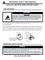 4
4
-
 5
5
-
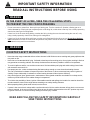 6
6
-
 7
7
-
 8
8
-
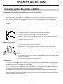 9
9
-
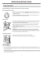 10
10
-
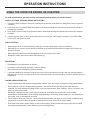 11
11
-
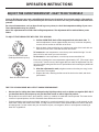 12
12
-
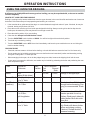 13
13
-
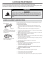 14
14
-
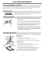 15
15
-
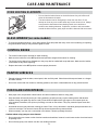 16
16
-
 17
17
-
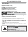 18
18
-
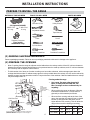 19
19
-
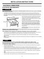 20
20
-
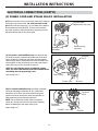 21
21
-
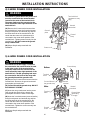 22
22
-
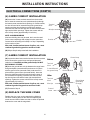 23
23
-
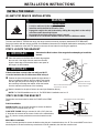 24
24
-
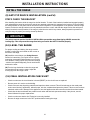 25
25
-
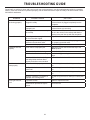 26
26
-
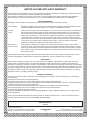 27
27
-
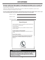 28
28
-
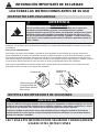 29
29
-
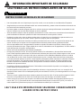 30
30
-
 31
31
-
 32
32
-
 33
33
-
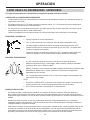 34
34
-
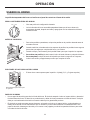 35
35
-
 36
36
-
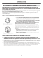 37
37
-
 38
38
-
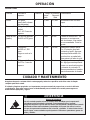 39
39
-
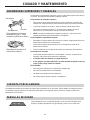 40
40
-
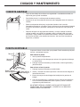 41
41
-
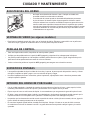 42
42
-
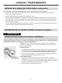 43
43
-
 44
44
-
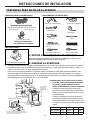 45
45
-
 46
46
-
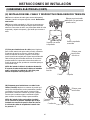 47
47
-
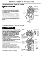 48
48
-
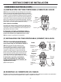 49
49
-
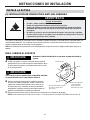 50
50
-
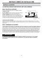 51
51
-
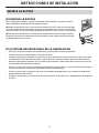 52
52
-
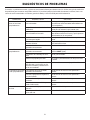 53
53
-
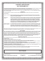 54
54
-
 55
55


en otros idiomas
- English: Danby DER201W Owner's manual
Artículos relacionados
-
Danby DER242BSS El manual del propietario
-
Danby DER240W El manual del propietario
-
-
Danby DER241WC El manual del propietario
-
-
-
Danby DR240WGLP El manual del propietario
-
-