Fanimation LP8321LAZ El manual del propietario
- Categoría
- Ventiladores domésticos
- Tipo
- El manual del propietario

Español p. 19
ITEM #0593755
MODEL #LP8321LAZ
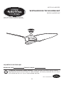
ANIVA BAY CEILING FAN
ATTACH YOUR RECEIPT HERE
Serial Number
Purchase Date
Lowes.com/harborbreeze
Harbor Breeze® is a registered trademark
of LF, LLC. All Rights Reserved.
EB14225
Questions, problems, missing parts? Before returning to your retailer, call our customer
service department at 1-800-643-0067, 8 a.m. - 6 p.m., EST, Monday - Thursday and
8 a.m. - 5 p.m., EST, Friday.
1

TABLE OF CONTENTS
3DFNDJH&RQWHQWV
Hardware Contents .......................................................................................................................
Safety Information .........................................................................................................................
3UHSDUDWLRQ
Assembly Instructions ...................................................................................................................
Wiring Instructions ........................................................................................................................
Final Assembly Instructions ..........................................................................................................
Operating Instructions ..................................................................................................................
Care and Maintenance .................................................................................................................
Troubleshooting ............................................................................................................................
Warranty .......................................................................................................................................
5HSODFHPHQW3DUWV/LVW
3
4
4
5
6
10
11
14
16
16
17
18
/RZHVFRPKDUERUEUHH]H
2

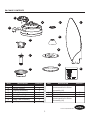
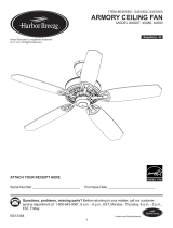
PACKAGE CONTENTS
J
B
A
L
F
G
C
D
H
I
K
Lowes.com/harborbreeze
E
YTITNAUQNOITPIRCSEDTRAP
A
B
C
D
E
F
G
H
1
1
1
1
1
1
1
1
Motor Assembly
Hanger Bracket
Downrod Assembly
Ceiling Canopy
Canopy Screw Cover
Motor Coupling Cover
Blade Plate Assembly
End Cap
YTITNAUQNOITPIRCSEDTRAP
I
J
K
L
3
3
1
1
Blade Cover
(preassembled to Motor
Assembly (A))
Blade
Remote Pack
Receiver Unit
(preassembled to Motor
Assembly (A))
2
H
3

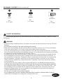
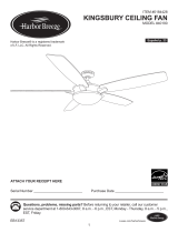
HARDWARE CONTENTS (shown actual size)
Wire
Connector
Qty.
3 + 1 extra
CC
Lowes.com/harborbreeze
Fiber
Washer
Qty.
9 + 1 extra
BB
SAFETY INFORMATION
Before you begin installing the fan, disconnect the power by removing fuses or turning off circuit
breakers.
'RQRWLQVWDOORUXVHIDQLIDQ\SDUWLVGDPDJHGRUPLVVLQJ
Make sure the installation site you choose allows a minimum clearance of 7 ft. from the blades
to the floor and at least 30 in. from the ends of the blades to any obstruction.
If you are mounting the fan to a ceiling outlet box, use a METAL octagonal outlet box, not plastic.
Secure the outlet box directly to the building structure. The outlet box and its support must be able
to support the moving weight of the fan (at least 35 lbs.).
To reduce the risk of fire, electrical shock, or personal injury, wire connectors provided with this
fan are designed to accept only one 12-gauge house wire and two lead wires from the fan. If
your house wire is larger than 12-gauge or there is more than one house wire to connect to the
two fan lead wires, consult an electrician for the proper size wire connectors to use. Before
cutting, drilling or hammering, verify their location. If needed, contact your electrician, plumber
or service person.
To reduce the risk of fire, electric shock or personal injury, do not bend the blade arms when
LQVWDOOLQJWKHPEDODQFLQJWKHEODGHVRUFOHDQLQJWKHIDQ'RQRWLQVHUWIRUHLJQREMHFWVEHWZHHQ
the rotating fan blades. Mount to outlet box marked “ACCEPTABLE FOR FAN SUPPORT” and
use mounting screws provided with the outlet box. Most outlet boxes commonly used for the
support of lighting fixtures are not acceptable for fan support and may need to be replaced.
Consult a qualified electrician if in doubt.
7KLVIDQLVWREHXVHGLQGU\RUGDPSORFDWLRQV
'RQRWRSHUDWHWKLVIDQZLWKDYDULDEOH5KHRVWDWZDOOFRQWUROOHURUGLPPHUVZLWFK'RLQJVR
could result in damage to the ceiling fan's remote control unit.
WARNING
Please read and understand this entire manual before attempting to assemble, operate or install
the product.
AA
Screw
Qty.
9 + 1 extra
4

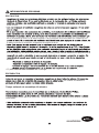
SAFETY INFORMATION
Note: This equipment has been tested and found to comply with the limits for Class B digital
device, pursuant to part 15 of the FCC Rules. These limits are designed to provide reasonable
protection against harmful interference in a residential installation. This equipment generates, uses
and can radiate radio frequency energy and, if not installed and used in accordance with the
instructions, may cause harmful interference to radio or television reception, which can be
determined by turning the equipment off and on, the user is encouraged to try to correct the
interference by one or more of the following measures:
- Reorient or relocate the receiving antenna.
- Increase the separation between the equipment and the receiver.
- Connect the equipment into an outlet on a circuit different from that to which the receiver is
connected.
The net weight of this fan is: 19.02 lbs.
Make sure all electrical connections comply with local codes, ordinances or the National
Electrical code. Hire a qualified electrician or consult a do-it-yourself wiring handbook if you are
unfamiliar with installing electrical wiring.
After you install the fan, make sure all connections are secure to prevent the fan from falling.
For supply connections, if the conductor of a fan is identified as a grounded conductor, then it
should be connected to a grounded conductor power supply. If the conductor of a fan is identified
as an ungrounded conductor, then it should be connected to an ungrounded conductor power
supply. If the conductor of a fan is identified for equipment grounding, then it should be connected
to an equipment-grounding conductor.
CAUTION
Before beginning assembly of product, make sure all parts are present. Compare parts with
package contents list and hardware contents list. If any part is missing or damaged, do not attempt
to assemble the product.
Estimated Assembly Time: 60 minutes
Tools Required for Assembly (not included):
stripper and step ladder.
Helpful Tools (not included): AC tester light, do-it-yourself wiring handbook and wire cutters.
This fan is intended for standard and angled mounting options only. Closemount and flushmount
options are not available. For angled ceilings, note the angle can be no more than 19°.
PREPARATION
5

ASSEMBLY INSTRUCTIONS
/RZHVFRPKDUERUEUHH]H
2
3
C
A
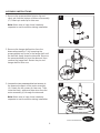
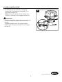
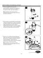
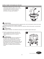
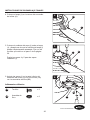
2. Remove the hanger ball portion from the
downrod assembly (C) by loosening the
preassembled set screw in the hanger ball until
the ball falls freely down the downrod. Remove
the preassembled pin from the downrod, then
remove the hanger ball. Retain the pin and
hanger ball for later use.
1
1. Remove the preassembled hairpin clip and
clevis pin from the bottom of downrod assembly
(C). Retain pin and clip for later use.
Note: Make sure to keep loose hardware
separate to avoid confusion during installation.
C
C
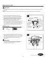
/RRVHQWKHWZRSUHDVVHPEOHGVHWVFUHZVLQ
the downrod support of the motor assembly
(A). Retain the set screws for later use. Then,
route the black, white and blue wires from the
motor assembly (A) through the downrod.
Note: Make sure to keep loose hardware
separate to avoid confusion during installation.
Set screw
6

ASSEMBLY INSTRUCTIONS
/RZHVFRPKDUERUEUHH]H
C
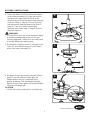
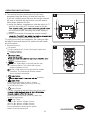
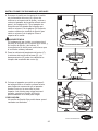
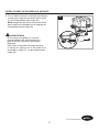
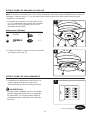
4. Thread the downrod into the downrod support
of the motor assembly (A). Align the holes in
the downrod support with the holes in the
downrod and re-install the previously removed
clevis pin (Step 1, page 6). Secure clevis pin
with previously removed hairpin clip (Step 1,
page 6). Then, re-install the previously
removed set screws (step 3, page 6) into the
downrod support.
5. Route motor coupling cover (F), canopy screw
cover (E) and ceiling canopy (D) over fixture
wires from motor assembly (A).
WARNING
It is critical the clevis pin in the downrod support
is properly installed and the set screws are
securely tightened. Failure to do so could result
in the fan falling and causing injury.
4
5
D
E
F
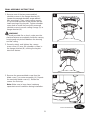
6. Re-attach the pin previously removed (Step 2,
page 6) into the downrod, then align the
hanger ball so the pin is captured in the
JURRYHDWWKHWRS3XOOWKHKDQJHUEDOOWLJKW
against the pin, then tighten the preassembled
set screw in hanger ball.
A loose set screw could result in a wobbly fan.
CAUTION
A
A
6
C
Set screw
7

WARNING
To avoid possible electrical shock, be sure electricity is turned off at the main fuse box before
hanging.
WARNING
The fan must hang with at least 7 ft. of clearance from the floor to blades.
B
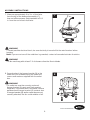
8. Securely attach the hanger bracket (B) to the
outlet box (not included) using the outlet box
screws and washers supplied with the outlet
box.
8
ASSEMBLY INSTRUCTIONS
/RZHVFRPKDUERUEUHH]H
7. Measure approximately 6 to 9 in. of lead wire
from the top of the downrod assembly (C),
WKHQFXWRIIWKHH[FHVV6WULSLQVXODWLRQRII
in. from the end of each lead wire.
7
C
Note: If you are not sure if the outlet box is grounded, contact a licensed electrician for advice.
WARNING
The outlet box must be securely anchored.
Hanger bracket (B) must seat firmly against
outlet box. If the outlet box is recessed, remove
wallboard until hanger bracket (B) contacts box.
,IKDQJHUEUDFNHW%DQGRURXWOHWER[DUHQRW
securely attached, the fan could wobble or fall.
8

ASSEMBLY INSTRUCTIONS
/RZHVFRPKDUERUEUHH]H
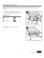
9. Carefully lift the fan assembly, resting the
hanger ball of the downrod assembly (C) on
the hanger bracket (B).
Note: Be sure the groove in the hanger ball
is lined up with tab on the hanger bracket (B).
WARNING
Failure to seat tab in groove could cause damage
to electrical wires and possible shock or fire
hazard.
To avoid possible shock, do not pinch wires
between the downrod assembly (C) and hanger
bracket (B).
B
C
9
9

/RZHVFRPKDUERUEUHH]H
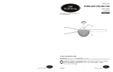
WIRING INSTRUCTIONS
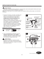
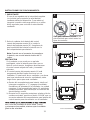
1. Connect the green grounding wire from the
downrod assembly (C) and the green grounding
wire from the hanger bracket (B) to the supply
grounding conductor (this may be a bare wire or
wire with green colored insulation). Securely
connect wires with wire connector (CC).
Securely connect the white fan motor wire to the
white supply (neutral) wire using wire connector
(CC). Securely connect the black fan motor wire
to the black supply wire using wire connector
(CC).
Hardware Used
CC
x 3
Wire
Connector
1
CC
CC
CC
CC
C
B
Green Wire
from Supply
(Ground)
White Wire
from Supply
White Wire
from Fan
Green Wire
from Downrod
Assembly
(Ground)
Green
Wire
White
Wire
Green Wire
from Hanger
Ball (Ground)
/LVWHG
Outlet Box
Household
Supply
Black Wire
from Supply
Black Wire
from Fan
Black Wire
2. After connections have been made, turn wires
upward and carefully push wires into the outlet
box, with the white and green wires to one side
of the box and the black wires toward the
other side.
2
To avoid possible electrical shock, be sure electricity is turned off at the main fuse box before wiring
this fan.
WARNING
Note: If you are not sure if the outlet box is grounded, contact a licensed electrician for advice.
WARNING
Check to see all connections are tight and no
bare wire is visible at the wire connectors
except for the ground wire.
10

1
D
2
FINAL ASSEMBLY INSTRUCTIONS
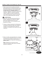
2. Securely attach and tighten the canopy
screw cover (E) over the shoulder screws in
the hanger bracket (B), utilizing the keyslot
twist-lock feature.
WARNING
To avoid possible fire or shock, make sure the
electrical wires are completely inside the canopy
housing and not pinched between the housing
and the ceiling.
/RZHVFRPKDUERUEUHH]H
E
A
I
1. Remove one of the two preassembled
shoulder screws in the hanger bracket (B).
/RRVHQWKHVHFRQGVKRXOGHUVFUHZZLWKRXW
fully removing it. Then, rotate ceiling canopy
(D) so second shoulder screw moves into the
small opening of the keyslot. Tighten shoulder
screw and re-install the previously removed
shoulder screw to secure ceiling canopy (D) to
hanger bracket (B).
3
3. Remove the preassembled screw from the
blade cover (I) on motor assembly (A). Repeat
for remaining blade covers (I). Retain the
screws for next step.
Note: Make sure to keep loose hardware
separate to avoid confusion during installation.
11

FINAL ASSEMBLY INSTRUCTIONS
/RZHVFRPKDUERUEUHH]H
5
3ODFHWKHEODGHFRYHU,RYHUWKHEODGH-
making sure blade cover (I) is fully seated.
Secure with previously removed screws (Step
3, page 11).
Repeat Steps 4 and 5 for remaining blades (J).
I
A
J
4
3RVLWLRQWKHEODGH-LQWRWKHVORWRIPRWRU
assembly (A).
A
J
6.
Securely tighten the blades (J) at the bottom of
the motor assembly (A) using the screws (AA)
with the fiber washers (BB).
Hardware Used
AA
Screw x 6
BB
Fiber
Washer
x 6
A
AA
BB
6
J
12

Hardware Used
AA
3 xwercS
BB
Fiber
Washer
x 3
FINAL ASSEMBLY INSTRUCTIONS
Lowes.com/harborbreeze
7.
Assemble the blade plate assembly (G)
to the support bracket of motor assembly (A)
using screws (AA) with the fiber washers (BB).
AA
7
A
G
8
8.
Assemble end cap (H) to the blade plate
assembly (G).
H
G
Note: If you are installing the fan along with the Aniva Bay Light Kit (Item #0618000, sold separately),
disregard Step 7 and Step 8 and refer to the light kit's instruction manual for how to complete
assembly.
13
BB

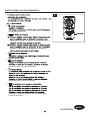
OPERATING INSTRUCTIONS
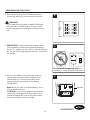
1. Restore electrical power to the outlet box by
turning the electricity on at the main fuse box.
2.
1
ON
ON
ON
ON
ON
ON
ON
ON
22
14
WARNING
Do not operate this fan with a variable (Rheostat)
wall controller or dimmer switch. Doing so could
result in damage to the ceiling fan's remote control
unit.
3. Remove the battery cover from the remote in
remote pack (K) and install the battery from
remote pack (K). Ensure the polarity of the
battery matches the polarity in the battery
compartment.
Note:
IMPORTANT: Using a full range dimmer switch
(not included) to control fan speed will damage
the fan. To reduce the risk of fire or electrical shock,
do not use a full range dimmer switch to control the
fan speed.
When it is time to replace battery, use a
12-volt alkaline battery.
23
12V
CAUTION: If you are not expecting to use the
remote for a long period of time, remove it to
prevent damage. Be sure to store the remote
away from excess heat or humidity.
Remote
For illustrative purposes only-not
intended to cover all types of controls

4. The remote from the remote pack (K) has been
programed from the factory to work with your fan.
If you are installing more than one fan and do not want
the fans to interfere with each other, you will need to
follow these steps for this fan:
a) Inside the battery compartment, slide dip switch to “1”
and turn fan power OFF. Restore power to the fan.
two musical sounds, indicating the power supply is
normal.
b) Within 30 seconds of hearing the musical sounds,
of remote to synchronize it with the fan.
To verify successful synchronization, the ceiling fan light
will blink 3 times and remain ON, and the fan will rotate
on HIGH speed.
12V
a
b
24
Remote
OPERATING INSTRUCTIONS
Sleep Timer:
2H: The fan will turn off after 2 hours.
4H: The fan will turn off after 4 hours.
8H: The fan will turn off after 8 hours.
During sleep timer mode, tap the power
button to cancel the function.
5
2
H
Remote
15
5. Remote functions:
The fan speed from 1-6, with 1 being the lowest and
6 being the highest
Fan speed:
= Natural breeze
:
.
p
indicator.
:
Turns the fan and light off after 1 minute.
During light delay mode, press any other key
to cancel the function.
Home Shield:
The fan is turned off with the light in the A-B-A cycle.
.
.
During home shield mode, press any other key
to cancel the function.
Reverse button:
Summer- Slide switch to the left and fan runs
counterclockwise. The airflow with normal
rotation cirulates cool air.
Winter- Slide switch to the right and fan rotates
clockwise. The airflow with reverse rotation
forces warm air downward.
dimming.

CARE AND MAINTENANCE
When cleaning, use only a soft brush or lint-free cloth to avoid scratching the finish.
$EUDVLYHFOHDQLQJDJHQWVDUHQRWUHTXLUHGDQGVKRXOGEHDYRLGHGWRSUHYHQWGDPDJHWRILQLVK
3HULRGLFOLJKWGXVWLQJRIWKHEODGHVLVUHFRPPHQGHG$IHDWKHUGXVWHUZLOOZRUNEHVW
$YRLGXVLQJZDWHUFOHDQVHUVRUKDUVKUDJVZKLFKFDQZDUSDQGUXLQWKHILQLVK
WARNING
Do not use water when cleaning the ceiling fan. It could damage the motor or the finish and
create the possibility of electrical shock.
3HULRGLFDOO\FKHFNWKDWWKHIDQPRWRUXQLWVFUHZVEODGHVFUHZVVXSSRUWKRXVLQJVFUHZVDUHWLJKW
and secure.
'RQRWLQVWDOORUXVHIDQLIDQ\SDUWLVGDPDJHGRUPLVVLQJ
/RZHVFRPKDUERUEUHH]H
TROUBLESHOOTING
4. Motor noise caused by solid state
variable speed control.
3. Wire connectors inside housing are
rattling.
1. Blades not attached to fan.
/RRVHVFUHZVLQPRWRUKRXVLQJ
1. Check main and branch circuit
fuses or circuit breakers.
2. Check line wire connections to
fan.
4. Some fan motors are sensitive
to signals from solid-state
variable speed controls.
Solid-state controls are not
recommended; choose an
alternative control method.
3. Check to make sure wire
connectors are secured tightly
inside housing.
1. Attach blades to fan before
operating.
2. Check to make sure all screws
in motor housing are snug
(do not overtighten).
PROBLEM POSSIBLE CAUSE CORRECTIVE ACTION
Fan will not start. 1. Fuse or circuit breaker blown.
2. /RRVHSRZHUOLQHFRQQHFWLRQV
3. Dead battery in remote control. 3. Replace with new battery.
to the fan.
Fan sounds noisy.
Fan wobbles
excessively.
1. Set screw in downrod support is
loose.
1. Tighten set screws securely in
downrod support.
WARNING
Turn off main power before attempting any troubleshooting.
16

WARRANTY
To obtain warranty service, present a copy of your sales receipt as proof of purchase. All cost of
removal and reinstallation are the expressed responsibility of the purchaser. Any damage to the
ceiling fan by accident, misuse or improper installation, or by affixing accessories not produced by
this warranty, are at the purchaser’s own responsibility. The manufacturer assumes no responsibility
whatsoever for fan installation during the lifetime limited warranty. Any service performed by an
unauthorized person will render the warranty invalid.
Due to varying climate conditions, this warranty does not cover changes in finish, rusting, pitting,
tarnishing, corroding or peeling. Fan finishes maintain their beauty when protected from varying
weather conditions. Any glass provided with this fan is not covered by the warranty.
Any replacement of defective parts for the ceiling fan must be reported within the first year from the
date of purchase. For the balance of the warranty, call our customer service department at
1-800-643-0067
for return authorization and shipping instructions so that we may repair or replace
the ceiling fan. Any fan or parts returned improperly packaged is the sole responsibility of the purchaser.
There is no further expressed warranty. The manufacturer disclaims any and all implied warranties.
The duration of any implied warranty which can not be disclaimed is limited to the lifetime limited
period as specified in our warranty. The manufacturer shall not be liable for incidental, consequential
or special damages arising at or in connection with product use or performance except as may
otherwise be accorded by law. This warranty gives you specific legal rights and you also have other
rights which vary from state to state. This warranty supersedes all prior warranties.
Note: A small amount of “wobble” is normal and should not be considered a defect.
The manufacturer warrants this fan to be free from defects in workmanship and material present at
time of shipment from the factory. The warranty terms from the date of purchase. The motor has a
lifetime warranty, and a 2 year warranty for the light kit and all remaining components. This warranty
applies only to the original purchaser. The manufacturer agrees to correct such defect at no charge
or, at our option, replace the ceiling fan with a comparable or superior model.
/RZHVFRPKDUERUEUHH]H
TROUBLESHOOTING
PROBLEM POSSIBLE CAUSE CORRECTIVE ACTION
Not enough air
movement.
Fan wobbles
excessively.
2. Set screw in downrod assembly is
loose.
4. Fan blades are out of balance.
3. Hanger bracket andRURXtlet box is
not securely fastened.
Too short of downrod.
2. Tighten the set screw in the
downrod assembly.
3. Tighten the hanger bracket
screws to the outlet box, and
secure outlet box.
4. Interchanging position of fan
blades can redistribute the
weight and result in a smoother
operation. For example,
exchange blades in positions 1
and 3 or 1 and 2.
If possible, consider using a
longer downrod (sold separately).
17

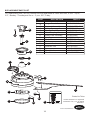
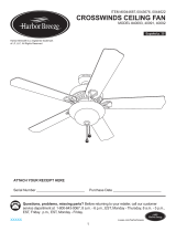
REPLACEMENT PARTS LIST
Printed in China
Lowes.com/harborbreeze
Harbor Breeze® is a registered
trademark of LF, LLC. All Rights
Reserved.
PART DESCRIPTION PART #
AMA8321LAZ
APGAC110RBL
ADRAC4GT1-45LAZ
P832101LAZ
APPAC1101LAZ
AP1115LAZ
AP832109BL
P832110LAZ
AP832105LAZ
AP832103N-HT8681
TR17
RECDC8321
HDWBM8321SSBL
HDWBM8321SSBL
HDWWNUTS4
Motor Assembly
Hanger Bracket
Downrod Assembly
Ceiling Canopy
Canopy Screw Cove r
Motor Coupling Cover
Blade Plate Assembly
End Cap
Blade Cover
Blade
Remote Pack
Receiver Unit
Screw
Fiber Washer
Wire Connector
A
B
C
D
E
F
G
H
I
J
K
L
AA
BB
CC
For replacement parts, call our customer service department at 1-800-643-0067, 8 a.m. - 6 p.m.,
EST, Monday - Thursday and 8 a.m. - 5 p.m., EST, Friday.
A
L
I
H
C
E
F
D
K
G
J
B
CC
2
H
AA
AA
BB
BB
18

Harbor Breeze® es una marca registrada
de LF, LLC. Todos los derechos reservados.
VENTILADOR DE TECHO ANIVA BAY
ARTÍCULO #0593755
MODELO #LP8321LAZ
Lowes.com/harborbreeze
ADJUNTAR SU RECIBO AQUÍ
Número de serie
Fecha de compra
¿Preguntas, problemas, piezas faltantes? Antes de volver a la tienda, llame a nuestro
Departamento de Servicio al Cliente al 1-800-643-0067, de lunes a jueves de 8 a.m. a 6 p.m.
y los viernes de 8 a.m. a 5 p.m., hora estándar del Este.
19

22
22
31
...................................................................................................................
...................................................................................................................................
..............................................................................................................
Preparación ...................................................................................................................................
iniciales ...........................................................................................
.............................................................................................................
..............................................................................................
...................................................................................................
..............................................................................................................
Solución de problemas ..................................................................................................................
.........................................................................................................................................
............................................................................................................
ÍNDICE

1
1
1
1
1
1
1
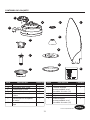
Ensamble del motor
Abrazadera para colgar
Ensamble del Varilla
Escudo del techo
Cubierta para los tornillos de
la base
Cubierta para el acoplador
del motor
Ensamble de la placa para
aspa
A
B
C
D
E
F
G
DADITNACNÓICPIRCSEDAZEIP
1
3
3
1
1
Tapa de extremo
Cubierta de aspa
(
preensamblado en el
ensamble de motor (A))
Aspa
Paquete remoto
Unidad receptora
(
preensamblado en el
ensamble de motor (A))
H
I
J
K
L
DADITNACNÓICPIRCSEDAZEIP
J
B
A
L
F
G
C
D
H
I
K
Lowes.com/harborbreeze
E
2
H
CONTENIDO DEL PAQUETE
21

ADVERTENCIA:
INFORMACIÓN DE SEGURIDAD
Lea y comprenda completamente este manual antes de intentar ensamblar, usar o instalar el
producto.
$QWHVGHFRPHQ]DUODLQVWDODFLyQGHOYHQWLODGRUdHVFRQHFWHODDOLPHQWDFLyQHOpFWULFDUHWLUDQGRORV
fusibles ocolocando el interruptor de circuito en la SRVLFLyQGHDSDJDGR
1RLQVWDOHQLXVHHVWHYHQWLODGRUVLIDOWDDOJXQDSLe]DRVLpVWDVHVWiQGDxDGDV
$VHJ~UHVHGHTXHHQHOOXJDUGHLQVWDODFLyQTXHelija se pueda establecer una distancia mínima de
2,13 m desde las aspas hasta el piso, y al menos 76,20 cm desde los extremos de las aspas hasta
FXDOTXLHUREVWiFXOR
6LGHVHDPRQWDUHOYHQWLODGRUHQXQDFDMDGHVDOLdDGHOWHFKRXVHXQDFDMDGHVDOLGDRFWRJRQDOGH
0(7$/QRGHSOiVWLFR$VHJXUHODFDMDGHVDOLGD directamente a la estructura del edificio. $VHJXUH
la caja directamente a la estructura del edificio. La caja de salida y su soporte deben ser capaces de
VRVWHQHUHOSHVRGHOYHQWLODGRUHQPRYLPLHQWRFoPRPtQLPRNJ
3DUDUHGXFLUHOULHVJRGHLQFHQGLRVGHVFDUJDVHlpctricas o lesiones personales, los conectores
GHFDEOHLQFOXLGRVFRQHVWHYHQWLODGRUHVWiQGLVexDGRVSDUDVRSRUWDUVyORXQFDEOHLQWHULRUGH
FDOLEUH\GRVFDEOHVFRQGXFWRUHVGHOYHQWLODGRr. Si el cable interior es de un calibre superior a
RKD\PiVGHXQFDEOHLQWHULRUSDUDFRQHFWDUOoVGRVFDEOHVFRQGXFWRUHVGHOYHQWLODGRr,
SUHJ~QWHOHDXQHOHFWULFLVWDFXiOHVVRQORVFRQHcWRUHVGHFDEOHGHWDPDxRFRUUHFWRTXHVH
deben usar.
3DUDUHGXFLUHOULHVJRGHLQFHQGLRVGHVFDUJDVHlpctricas o lesiones personales, no doble los
EUD]RVGHODVDVSDVDOLQVWDODUODVDOHTXLOLEUDUODV RDOOLPSLDUHOYHQWLODGRr1RLQWURGX]FDREMHWRV
H[WUDxRVHQWUHODVDVSDVHQPRYLPLHQWR,QVWDOHen una caja de salida marcada como
³$&&(3T$%/()25)$16833257´$3T$3$5$623257('(9(17,/$'25\XVHORV
WRUQLOORVGHPRQWDMHTXHVHSURSRUFLRQDQFRQODFaja de salida. La mayoría de las cajas de salida
TXHVHXVDQFRP~QPHQWHSDUDVRVWHQHUHQVDPEOeVGHLOXPLQDFLyQQRVRQDSWDVSDUDVRVWHQHU
XQYHQWLODGRU\SXHGHVHUQHFHVDULRUHHPSOD]DUODs. Si tiene dudas, consulte con un electricista
calificado.
(VWHYHQWLODGRUHVDSWRVyORSDUDOXJDUHVVHFRVR
1RXWLOLFHHVWHYHQWLODGRUFRQXQFRQWURODGRUYDULDbOHGHSDUHG5KHRVWDWRXQUHJXODGRUGH
LQWHQVLGDG6LORKLFLHUDSRGUtDGDxDUODXQLGDGGHlPDQGRDGLVWDQFLDGHOYHQWLODGRUGHWHFKR
K~PHGRV
/RZHVFRPKDUERUEUHH]H
$UDQGHODGH
fibra
&DQW
9 + 1 extra
BB
ADITAMENTOS
6HPXHVWUDHQWDPDxRUHDO
CC
&RQHFWRUHV
de cable
&DQW. 3+1 extra
AA
Tornillos
&DQWextra
22

INFORMACIÓN DE SEGURIDAD
usted mismo.
no es de puesta a tierra, se le debe conectar a un suministro de electricidad con conductor sin
le debe conectar al conductor de equipos de puesta a tierra.
si no se instala y usa de acuerdo con las instrucciones, puede causar interferencia perjudicial a la
medidas:
PRECAUCIÓN
. No intente ensamblar el
Tiempo estimado de ensamblaje: 60 minutos
cortacables.
PREPARACIÓN
El peso neto de este ventilador es: 8,63 kgs.

INSTRUCCIONES DE ENSAMBLAJE INICIALES
/RZHVFRPKDUERUEUHH]H
2
3
C
A
1
C
$IORMH los dos tornillos preensamblados de
ILMDFLyQGHOVRSRUWHGHODYDULOODGHOHQVDPEOH
GHOPRWRU$*XDUGHORVWRUQLOORVGHILMDFLyQ
SDUDPiVDGHODQWH/XHJRSDVHORV
FRQGXFWRUHVQHJUREODQFR\D]XOGHOHQVDPEOH
GHOPRWRU$DWUDYpVGHODYDULOOD
Nota: $VHJ~UHVHGHPDQWHQHUWRGRHO
DGLWDPHQWRVHSDUDGRSDUDHYLWDUFRQIXQGLUOR
durante la instalación.
5HWLUHHOVXMHWDGRUGHKRUTXLOODGHO
SUHHQVDPEODGR\SDVDGRUGHKRUTXLOODGHOD
SDUWHLQIHULRUGHOHQVDPEOHGHODYDULOOD&
Guarde los tornillos para más adelante.
Nota: $VHJ~UHVHGHPDQWHQHUWRGRHO
DGLWDPHQWRVHSDUDGRSDUDHYLWDUFRQIXQGLUOR
durante la instalación.
5HWLUHODSDUWHFRUUHVSRQGLHQWHDODERODSDUD
FROJDUGHOHQVDPEOHGHODYDULOOD&DIORMDQGR
HOWRUQLOORGHILMDFLyQGHODERODKDVWDTXHpVWD
VDOJDOLEUHPHQWHGHODYDULOOD5HWLUHHO
SDVDGRUSUHHQVDPEODGRGHODYDULOOD\OXHJR
UHWLUHODERODSDUDFROJDU*XDUGHHOSDVDGRU\
ODERODSDUDFROJDUSDUDSDVRVSRVWHULRUHV
Tornillo de
fijación

6
C
Tornillo de
fijación
INSTRUCCIONES DE ENSAMBLAJE INICIALES
/RZHVFRPKDUERUEUHH]H
C
(QURVTXHODYDULOODHQHOVRSRUWHGHODYDULOOD
HQHOHQVDPEOHGHOPRWRU$$OLQHHORV
RULILFLRVHQHOVRSRUWHGHODYDULOOD\YXHOYDD
FRORFDUHOSDVDGRUGHKRUTXLOODUHWLUDGRHQHO
SDVRGHODSiJLQD)LMHHOSDVDGRUGH
KRUTXLOODFRQHOVXMHWDGRUGHKRUTXLOODTXH
UHWLUyHQHOSDVRGHODSiJLQD'HVSXpV
YXHOYDDFRORFDUORVWRUQLOORVGHILMDFLyQTXH
UHWLUyHQHOSDVRGHODSiJLQDHQHO
VRSRUWHGHODYDULOOD
4
5
D
E
F
A
A
3DVHODFXELHUWDGHODFRSODGRUGHOPRWRU)
ODFXELHUWDGHOWRUQLOORGHODEDVH(\OD
EDVHSDUDWHFKR'VREUHORVFDEOHVGHOD
OiPSDUDGHOHQVDPEOHGHOPRWRU$
ADVERTENCIA
Es fundamental que instale correctamente el
pasador de Korquilla en el soporte deODYarilla, y
los tornillos de fijación y las tuercas. El
incumplimiento de dicKo paso podrta Kacer que
el Yentilador FDtGDV\OHVLRQHV
&RORTXHHOSDVDGRUTXHUHWLUyHQHOSDVR
GHODSiJLQDHQODYDULOOD\DOLQHHODEROD
SDUDFROJDUGHPDQHUDWDOTXHHOSDVDGRU
quede inserto en la ranura de la parte
VXSHULRU-DOHODERODSDUDFROJDUFRQWUDHO
pasador y apriete el tornillo de fijación
SUHHQVDPEODGRHQODERODSDUDFROJDU
8QWRUQLOORGHILMDFLyQIORMRSRGUtDKDFHUTXHHO
YHQWLODGRUVHWDPEDOHH
PRECAUCIÓN

INSTRUCCIONES DE ENSAMBLAJE INICIALES
B
8
/RZHVFRPKDUERUEUHH]H
0LGDDSUR[LPDGDPHQWHHQWUH\
cm de cable conductor desde la parte superior
GHOHQVDPEOHGHODYDULOOD&\FRUWHHO
H[FHGHQWH3HOHFPGHODLVODPLHQWR
GHOH[WUHPRGHFDGDFDEOHFRQGXFWRU
7
C
FPD
FP
)LMHELHQODDEUD]DGHUDSDUDFROJDU%DOD
FDMDGHVDOLGDQRVHLQFOX\HFRQORVWRUQLOORV
\ODVDUDQGHODVSURYLVWDVFRQODFDMDGH
salida.
ADVERTENCIA
La caja de salida debe estar bien aVHJurada. La
abra]DGera paraFROJDr % debe estar bien
asentada contra la caja de salida. Si la caja de
salida está empotrada, retire el panel de fibra
SUHQVDGDKDVWDTXHODDEUD]DGHUDSDUDFROJDU%
KDJDFRQWDFWRFRQODFDMDSi la abra]DGera para
FROJDU%\RODcaja de salida no están bien
aVHJuradas, eOYHntilador podrtDtambalearse o
caerse.
3DUDHYLWDUXQDSRVLEOHGHVFDUJDHOpFWULFDDVHJ~UHVHGHFRUWDUODDOLPHQWDFLyQHOpFWULFDGHODFDMD
GHIXVLEOHVSULQFLSDODQWHVGHFROJDUHOYHQWLODGRU
'HEHFROJDUHOYHQWLODGRUDXQDGLVWDQFLDPtQLPDGHPGHVGHODVDVSDVKDVWDHOSLVR
Nota: 6LQRHVWiVHJXURGHVLODFDMDGHVDOLGDWLHQHFRQH[LyQDWLHUUDSLGDFRQVHMRDXQHOHFWULFLVWD
certificado.
ADVERTENCIA
ADVERTENCIA

INSTRUCCIONES DE ENSAMBLAJE INICIALES
/RZHVFRPKDUERUEUHH]H
B
C
9
&RQFXLGDGROHYDQWHHOHQVDPEOHGHSRVLWDQGR
ODERODSDUDFROJDUGHOHQVDPEOHGHODYDULOOD
&HQODDEUD]DGHUDSDUDFROJDU%
Nota: $VHJ~UHVHGHTXHODUDQXUDGHODEROD
SDUDFROJDUHVWpDOLQHDGDFRQODOHQJHWDGH
ODDEUD]DGHUDSDUDFROJDU%
ADVERTENCIA
6LQRFRORFDODOHQJHWDHQODUDQXUD
SRGUtDQGDxDUVHlRVFDEOHVHOpFWULFRV\
SRGUtDQRFXUULULQFHQGLRVRGHVFDUJDV
HOpFWULFDV
3DUDHYLWDUXQDSRVLEOHGHVFDUJDHOpFWULFD
no apriete los cables entre el ensamble de la
HQVDPEOHODYDULOOD&\ODDEUD]DGHUDSDUD
FROJDU%

/RZHVFRPKDUERUEUHH]H
1
CC
CC
CC
CC
C
B
&RQGXFWRU
YHUGH
&RQGXFWRU
blanco
&RQGXFWRU
QHJUR
2
INSTRUCCIONES DE CABLEADO
Nota: 6LQRHVWiVHJXURGHVLODFDMDGHVDOLGDWLHQHFRQH[LyQDWLHUUDSLGDFRQVHMRDXQHOHFWULFLVWD
certificado.
ADVERTENCIA
3DUDHYLWDUXQDSRVLEOHGHVFDUJDHOpFWULFDDVHJ~UHVHGHFRUWDUODDOLPHQWDFLyQHOpFWULFDGHODFDMD
GHIXVLEOHVSULQFLSDODQWHVGHFDEOHDGRHOYHQWLODGRU
Aditamentos utilizados
CC
[
&RQHFWRUHV
de cable
&RQHFWHHOFRQGXFWRUYHUGHGHOHQVDPEOHGHOD
YDULOOD&\HOFRQGXFWRUYHUGHFRQSXHVWDD
WLHUUDGHODDEUD]DGHUDSDUDFROJDU%DO
conductor de suministro con puesta a tierra
SRVLEOHPHQWHXQFRQGXFWRUGHVQXGRRXQ
FDEOHFRQDLVODQWHYHUGH&RQHFWHORV
FRQGXFWRUHVFRQFRQHFWRUHVGHFDEOHV&&GH
IRUPDVHJXUD&RQHFWHHOFRQGXFWRUEODQFRGHO
PRWRUGHOYHQWLODGRUDOFRQGXFWRUEODQFR
QHXWURPHGLDQWHHOFRQHFWRU&&GHIRUPD
VHJXUD&RQHFWHGHIRUPDVHJXUDHOFRQGXFWRU
QHJURGHOPRWRUGHOYHQWLODGRUDOFRQGXFWRU
QHJURPHGLDQWHHOFRQHFWRU&&
8QDYH]UHDOL]DGDVODVFRQH[LRQHVJLUHORV
FRQGXFWRUHVKDFLDDUULED\FRQFXLGDGR
colóquelos dentro de la caja de salida; con los
FRQGXFWRUHVEODQFRV\YHUGHVKDFLDXQODGR\
ORVFRQGXFWRUHVQHJURVKDFLDHORWUR
&RQGXFWRUYHUGH
SXHVWDDWLHUUD
&RQGXFWRUEODQFR
del suministro
&RQGXFWRU
blanco del
YHQWLODGRU
&DMDGHVDOLGD
KRPRORJDGD
Suministro
HOpFWULFR
&RQGXFWRU
QHJUR
del suministro
&RQGXFWRU
QHJURGHO
YHQWLODGRU
&RQGXFWRU
YHUGHSXHVWD
DWLHUUDGHVGH
el ensamble
GHYDULOOD
&RQGXFWRUYHUGH
SXHVWDDWLHUUD
desdela
DEUD]DGHUDSDUD
FROJDU
ADVERTENCIA
9HULILTXHTXHWRGDVODVFRQH[LRQHVHVWpQ
ajustadas y que no Kaya conductores desnudos
YLVLEOHVHQORVFRQHFWRUHVH[FHSWRHOFRQGXFWRU
FRQFRQH[LyQDWLHUUD

1
D
2
/RZHVFRPKDUERUEUHH]H
E
A
I
3
5HWLUHHOWRUQLOORSUHHQVDPEODGRGHODFXELHUWD
GHODVSD,GHOHQVDPEOHGHOPRWRU$5HSLWD
el procedimiento para las cubiertas de las
DVSDV,UHVWDQWHV*XDUGHORVWRUQLOORVSDUDHO
SUy[LPRSDVR
Nota: $VHJ~UHVHGHPDQWHQHUWRGRHO
DGLWDPHQWRVHSDUDGRSDUDHYLWDUFRQIXQGLUOR
durante la instalación.
INSTRUCCIONES DE ENSAMBLAJE FINALES
5HWLUHXQRGHORVGRVWRUQLOORVGHUHERUGH
SUHHQVDPEODGRVHQHODEUD]DGHUDSDUDFROJDU
%$IORMHHOVHJXQGRWRUQLOORGHUHERUGHVLQ
UHWLUDUORGHOWRGR/XHJRJLUHODEDVHGHWHFKR
'GHPRGRTXHHOVHJXQGRWRUQLOORGH
UHERUGHVHGHVSODFHDODDEHUWXUDSHTXHxDGHO
FKDYHWHUR$SULHWHHOWRUQLOORGHUHERUGH\
YXHOYDDLQVWDODUHOWRUQLOORGHUHERUGHTXH
retiró anteriormente para ajustar la base del
WHFKR'DODDEUD]DGHUDSDUDFROJDU%
ADVERTENCIA
3DUDHYLWDUXQDSRVLEOHGHVFDUJDHOpFWULFDR
LQFHQGLRDVHJ~UHVHGHFRORFDUORVFDEOHV
HOpFWULFRVFRPSOHWDPHQWHGHQWURGHOD
carcasa de la base, y de no apretarlos entre
ODFDUFDVD\HOWHFKR
2. &RORTXH\DMXVWHILUPHPHQWHODFXELHUWDSDUD
HOWRUQLOORGHODEDVH(VREUHORVWRUQLOORVGH
UHERUGHGHODDEUD]DGHUDSDUDFROJDU
%
PHGLDQWHHOPHFDQLVPRGHVHJXURSRUJLURGHO
FKDYHWHUR

A
AA
BB
6
J
/RZHVFRPKDUERUEUHH]H
5
&RORTXHODFXELHUWDGHODVSD,VREUHHODVSD
-\DVHJ~UHVHGHTXHODFXELHUWDGHODVSD,
TXHGHFRPSOHWDPHQWHDVHQWDGD)LMHFRQORV
WRUQLOORVTXHUHWLUyHQHOSDVRGHODSiJLQD
5HSLWDORVSDVRV\SDUDODVDVSDV
UHVWDQWHV-
I
A
J
4
&RORTXHHODVSD-HQODUDQXUDGHOHQVDPEOH
GHOPRWRU$
A
J
$SULHWHODVDVSDV-HQODSDUWHLQIHULRUGHO
HQVDPEOHGHOPRWRU$FRQORVWRUQLOORV$$
FRQODVDUDQGHODVGHILEUD%%
BB
[
Aditamentos utilizados
AA
Tornillos [
INSTRUCCIONES DE ENSAMBLAJE FINALES
$UDQGHODGH
fibra

Lowes.com/harborbreeze
Nota: Si instala el ventilador junto con el kit de iluminación Aniva Bay (Artículo #0618000, se vende por
separado), omita los pasos 7 y 8 y consulte el manual de instrucciones del kit de iluminación para
completar el ensamblado.
INSTRUCCIONES DE ENSAMBLAJE FINALES
31
7.
Ensamble el ensamble de la placa para aspa
(G) en la abrazadera de soporte del ensamble
del motor (A) con los tornillos (AA) con las
arandelas de fibra (BB).
Aditamentos utilizados
AA
3 x
3 x
sollinroT
AA
7
A
G
8
8.
Coloque la tapa de extremo (H) en el ensamble
de la placa para aspa (G).
H
G
BB
fibra
1
ON
ON
ON
ON
ON
ON
ON
ON
INSTRUCCIONES DE FUNCIONAMIENTO
ADVERTENCIA
No utilice este ventilador con un controlador
variable de pared (Rheostat) o un regulador
de intensidad. Si lo hiciera podría dañar la
unidad del mando a distancia del ventilador
de techo.
1. Restablezca la alimentación eléctrica en la
caja de salida volviendo a conectar la
electricidad de la caja de fusibles principal.

4. El control remoto del paquete remoto (K) está
programado de fábrica para funcionar con su
ventilador. Si instala más de un ventilador y no desea
que haya interferencia entre los ventiladores, debe
seguir estos pasos para este ventilador:
a) Dentro del compartimiento para batería, deslice el
interruptor magnético a “1” y apague el ventilador.
Restablezca la alimentación al ventilador. La unidad
receptora (L) del ensamble del motor (A) emitirá dos
sonidos musicales, que indican que el suministro de
electricidad es normal.
b) Durante los 30 segundos posteriores a haber oído los
sonidos musicales, presione el botón “LEARN” que se
encuentra adentro del compartimiento para batería del
control remoto para sincronizarlo con el ventilador.
bien, la luz del ventilador de techo titilará 3 veces
y permanecerá encendida, mientras que el ventilador
girará a alta velocidad.
12V
a
b
24
Remoto
Lowes.com/harborbreeze
INSTRUCCIONES DE FUNCIONAMIENTO
3. R
2. IMPORTANTE
El uso de un regulador de la intensidad completa
(no incluido) para controlar la velocidad del
ventilador dañará el dispositivo. Para reducir el
riesgo de incendio o descarga eléctrica, no utilice
dicho regulador para controlar la velocidad del
ventilador.
etire la cubierta de la batería del control
remoto del paquete remoto (K) e instale la
batería del paquete remoto (K). Asegúrese de
que la polaridad de la batería coincida con la
del compartimiento para batería.
Nota: Cuando sea el momento de reemplazar
la batería, use una de batería alcalina de 12
voltios.
Si el producto no se usará por un período
prolongado, retire la batería para evitar que se
dañe el control remoto. Asegúrese de almacenar
el control remoto alejado del calor y humedad
extremos.
PRECAUCIÓN
23
12V
Remoto
32
22
Solo para referencia visual-no ha
sido diseñado para cubrir todos los
tipos de controles

el indicador de sonido.
otro botón para cancelar la función.
manecillas del reloj. El flujo de aire formado por la
del reloj. El flujo de aire formado por la rotación
5
2
H
INSTRUCCIONES DE FUNCIONAMIENTO
:
otrobotón para cancelar la función.
automático, presione el botón de encendido para
cancelar la función.
5.

/RZHVFRPKDUERUEUHH]H
8VHVyORXQDEURFKDVXDYHRXQSDxRVLQSHOXVDVSDUDHYLWDUUD\DUHODFDEDGRDOOLPSLDUODV
/RVDJHQWHVOLPSLDGRUHVDEUDVLYRVVRQLQQHFHVDULRV\GHEHQHYLWDUVHSDUDQRGDxDUHO
acabado.
6HUHFRPLHQGDXQDOLPSLH]DVXDYHGHOSROYRGHODVDVSDVSHULyGLFDPHQWH/RLGHDOHVXVDUXQ
plumero de plumas.
(YLWHXVDUDJXDOLPSLDGRUHVRWUDSRViVSHURV\DTXHSXHGHQFRPEDU\DUUXLQDUHODFDEDGR
CUIDADO Y MANTENIMIENTO
1RXVHDJXDSDUDOLPSLDUHOYHQWLODGRUGHWHFKR3XHGHGDxDUHOPRWRURHODFDEDGR\FUHDOD
SRVLELOLGDGGHXQDGHVFDUJDHOpFWULFD
5HYLVDUSHULyGLFDPHQWHTXHORVWRUQLOORVGHOPRWRUORVWRUQLOORVGHODVDVSDVODFDUFDVDGH
VRSRUWH\ORVWRUQLOORVGHONLWGHLOXPLQDFLyQGHOYHQWLODGRUHVWpQDSUHWDGRV\ILUPHV
1RLQVWDOHQLXVHHOYHQWLODGRUVLIDOWDDOJXQDSLH]DRVLpVWDVHVWiQGDxDGDV
ADVERTENCIA
ADVERTENCIA
$SDJXHODDOLPHQWDFLyQSULQFLSDODQWHVGHLQWHQWDUVROXFLRQDUFXDOTXLHUSUREOHPD
SOLUCIÓN DE PROBLEMAS
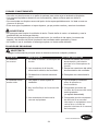
5HHPSODFHFRQQXHYDEDWHUtD
(OYHQWLODGRUHPLWH
PXFKRUXLGR
PROBLEMA CAUSA POSIBLE ACCIÓN CORRECTIVA
(OYHQWLODGRU
no arranca.
Se fundió un fusible o el interruptor de
circuito.
2. Las cone[iones de la ltnea de
alimentación HOpFtrica del Yentilador.
6LQEDWHUtDHQHOFRQWUROUHPRWRGH
mano.
/DVDVSDVQRHVWiQVXMHWDVDO
YHQWLODGRr.
2. Hay tornillos flojos en la carcasa del
motor.
)LMHODVDVSDVDOYHQWLODGRU
antes de ponerlo en
funcionamiento.
2. &RPSUXHEHTXHWRGRVORV
tornillos de la carcasa del motor
HVWpQDMXVWDGRV
QRDSULHWHGHPDVLDGR
/RVFRQHFWRUHVDOLQWHULRUGHOD
carcasa repiquetean.
&RPSUXHEHTXHORVFRQHFWRUHV
de cable de la carcasa del
interruptor no repiqueteen unos
contra otros o contra las
paredes interiores de la carcasa
del interruptor.
5HYLVHORVIXVLEOHVGHOFLUFXLWR
GHGHULYDFLyQ\GHOFLUFXLWR
principal o los interruptores de
circuito.
2. 5HYLVHODVFRQH[LRQHVGHOFDEOH
GHDOLPHQWDFLyQGHOYHQWLODGRU

/RZHVFRPKDUERUEUHH]H
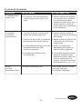
SOLUCIÓN DE PROBLEMAS
(OYHQWLODGRUHPLWH
PXFKRUXLGR
PROBLEMA CAUSA POSIBLE ACCIÓN CORRECTIVA
(OYHQWLODGRU
se tambalea
H[FHVLYDPHQWH
El tornillo de fijación y la tuerca del
VRSRUWHGHODYDULOODHVWiQIORMRV
)LMHELHQDPERVWRUQLOORVGH
fijación y sus tuercas al soporte
GHODYDULOOD
2. El tornillo de fijación del ensamble de
ODERODSDUDFROJDUYDULOODHVWiIORMR
2. $SULHWHHOWRUQLOORGHILMDFLyQHQ
el ensamble de la bola para
FROJDUYDULOOD
/DDEUD]DGHUDSDUDFROJDU\RODFDMD
GHVDOLGDGHOWHFKRQRHVWiQ
firmemente ajustados.
$MXVWHORVWRUQLOORVGHOD
DEUD]DGHUDSDUDFROJDUDOD
FDMDGHVDOLGD\DVHJ~UHOD
/DVDVSDVGHOYHQWLODGRUHVWiQ
desequilibradas.
1RKD\
suficiente
PRYLPLHQWRde aire.
6LHVSRVLEOHSLHQVHHQXWLOL]DU
XQDYDULOODPiVODUJD
VHYHQGHSRUVHSDUDGR
/DYDULOODHVGHPDVLDGRFRUWD
(OFRQWUROGHYHORFLGDGYDULDEOHGH
estado sólido produce ruidos en el
motor.
$OJXQRVPRWRUHVGHYHQWLODGRU
son sensibles a las VHxDOHV de
los controles GHYHORFLGDG
YDULDEOH de estado sólido. No se
recomiendan los controles de
estado sólido, elija un mptodo de
control alternatiYo.
,QWHUFDPELDUODSRVLFLyQGHODV
DVSDVGHOYHQWLODGRUSXHGH
UHGLVWULEXLUHOSHVR\KDFHUTXH
IXQFLRQHVXDYHPHQWH3RU
ejemplo, intercambie las aspas
GHODVSRVLFLRQHV\R\

GARANTÍA
(OIDEULFDQWHJDUDQWL]DTXHHVWHYHQWLODGRUQRSUHVHQWDGHIHFWRVQLGHIDEULFDFLyQQLHQORV
PDWHULDOHVSUHVHQWHVHQHOPRPHQWRGHOWUDQVSRUWHGHVGHODIiEULFD(VWDJDUDQWtDDSDUWLUGHOD
IHFKDGHFRPSUDDxRVGHJDUDQWtDSDUDHOMXHJRGHOXFHV\WRGRVORVFRPSRQHQWHVUHVWDQWHV
(VWDJDUDQWtDHVYiOLGDVyORSDUDHOFRPSUDGRURULJLQDO(OIDEULFDQWHDFHSWDUHSDUDUGLFKRVGHIHFWRV
VLQFDUJRRVHJ~QQXHVWURFULWHULRUHHPSOD]DUHOYHQWLODGRUGHWHFKRSRUXQPRGHORFRPSDUDEOHR
superior.
3DUDREWHQHUHOVHUYLFLRGHJDUDQWtDSUHVHQWHXQDFRSLDGHOUHFLERGHYHQWDFRPRSUXHEDGHOD
DGTXLVLFLyQ7RGRVORVFRVWRVGHH[WUDFFLyQ\UHLQVWDODFLyQVRQUHVSRQVDELOLGDGH[SOtFLWDGHO
FRPSUDGRU&XDOTXLHUGDxRDOYHQWLODGRUGHWHFKRSURGXFLGRSRUDFFLGHQWHXVRLQGHELGRR
LQVWDODFLyQLQFRUUHFWDRDFDXVDGHDFFHVRULRVGHILMDFLyQTXHQRHVWiQFXELHUWRVSRUHVWDJDUDQWtD
VHUiUHVSRQVDELOLGDGGHOFRPSUDGRU(OIDEULFDQWHQRDVXPHQLQJ~QWLSRGHUHVSRQVDELOLGDGSRUOD
LQVWDODFLyQGHOYHQWLODGRUGXUDQWHODJDUDQWtDOLPLWDGDGHSRUYLGD&XDOTXLHUVHUYLFLRUHDOL]DGRSRU
XQDSHUVRQDQRDXWRUL]DGDLQYDOLGDUiODJDUDQWtD
'HELGRDODVFDPELDQWHVFRQGLFLRQHVFOLPiWLFDVHVWDJDUDQWtDQRFXEUHFDPELRVHQHODFDEDGRGH
ODWyQy[LGRSLFDGXUDVGHVOXVWUHFRUURVLyQRGHVFDVFDUDPLHQWR/RVYHQWLODGRUHVFRQDFDEDGRGH
ODWyQPDQWLHQHQVXEHOOH]DFXDQGRVHOHVSURWHJHGHODVFDPELDQWHVFRQGLFLRQHVDWPRVIpULFDV/D
JDUDQWtDQRFXEUHORVHOHPHQWRVGHYLGULRLQFOXLGRVFRQHVWHYHQWLODGRU
(OUHHPSOD]RGHSLH]DVGHIHFWXRVDVSDUDHOYHQWLODGRUGHWHFKRGHEHLQIRUPDUVHGHQWURGHOSULPHU
DxRDSDUWLUGHODIHFKDGHFRPSUD3DUDFRQRFHUHOVDOGRGHODJDUDQWtDOODPHDQXHVWUR
'HSDUWDPHQWRGH6HUYLFLRDO&OLHQWHDO\REWHQJDODDXWRUL]DFLyQSDUDODGHYROXFLyQ\
ODVLQVWUXFFLRQHVGHHQYtRGHPRGRTXHSRGDPRVUHSDUDURUHHPSOD]DUHOYHQWLODGRUGHWHFKR8Q
YHQWLODGRURSLH]DVGHYXHOWDVFRQXQHPEDODMHLQFRUUHFWRVRQGHUHVSRQVDELOLGDG~QLFDGHO
FRPSUDGRU1RH[LVWHRWURWLSRGHJDUDQWtDH[SOtFLWD(OIDEULFDQWHUHFKD]DFXDOTXLHUD\WRGDVODV
JDUDQWtDVLPSOtFLWDV
/DGXUDFLyQGHFXDOTXLHUJDUDQWtDLPSOtFLWDTXHQRSXHGDUHFKD]DUVHVHOLPLWDDOSHUtRGROLPLWDGRGH
SRUYLGDHVSHFLILFDGRHQQXHVWUDJDUDQWtD(OIDEULFDQWHQRVHUiUHVSRQVDEOHGHGDxRV
circunstanciales, resultantes o especiales que surjan en relación con el uso o el funcionamiento del
SURGXFWRH[FHSWRTXHODOH\LQGLTXHORFRQWUDULR(VWDJDUDQWtDOHGDGHUHFKRVOHJDOHVHVSHFtILFRV\
DGHPiVXVWHGWLHQHRWURVGHUHFKRVTXHYDUtDQVHJ~QHOHVWDGR(VWDJDUDQWtDVXVWLWX\HFXDOTXLHU
JDUDQWtDSUHYLD
1RWD8QDSHTXHxDFDQWLGDGGH³WDPEDOHR´HVQRUPDO\QRVHGHEHFRQVLGHUDUFRPRXQGHIHFWR

Lowes.com/harborbreeze
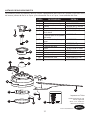
AMA8321LAZ
APGAC110RBL
ADRAC4GT1-45LAZ
P832101LAZ
APPAC1101LAZ
AP1115LAZ
AP832109BL
P832110LAZ
AP832105LAZ
AP832103N-HT8681
TR17
RECDC8321
HDWBM8321SSBL
HDWBM8321SSBL
HDWWNUTS4
Ensamble del motor
Abrazadera para colgar
Varilla
Escudo del techo
Cubierta para los tornillos
de la base
Cubierta para el acoplador
del motor
Ensamble de la placa para
aspa
Tapa de extremo
Cubierta de aspa
Aspa
Paquete remoto
Unidad receptora
Tornillos
Arandela de fibra
Conectores de cable
A
B
C
D
E
F
G
H
I
J
K
L
AA
BB
CC
PIEZA DESCRIPCIÓN PIEZA #
LISTA DE PIEZAS DE REPUESTO
Para obtener piezas de repuesto, llame a nuestro Departamento de Servicio al Cliente al 1-800-643-0067,
de lunes a jueves de 8 a.m. a 6 p.m. y los viernes de 8 a.m. a 5 p.m., hora estándar del Este.
Impreso en China
Harbor Breeze® es una
marca registrada
de LF, LLC. Todos los
derechos reservados.
37
A
L
I
H
C
E
F
D
K
G
J
B
CC
2
H
AA
AA
BB
BB
-
 1
1
-
 2
2
-
 3
3
-
 4
4
-
 5
5
-
 6
6
-
 7
7
-
 8
8
-
 9
9
-
 10
10
-
 11
11
-
 12
12
-
 13
13
-
 14
14
-
 15
15
-
 16
16
-
 17
17
-
 18
18
-
 19
19
-
 20
20
-
 21
21
-
 22
22
-
 23
23
-
 24
24
-
 25
25
-
 26
26
-
 27
27
-
 28
28
-
 29
29
-
 30
30
-
 31
31
-
 32
32
-
 33
33
-
 34
34
-
 35
35
-
 36
36
-
 37
37


Fanimation LP8321LAZ El manual del propietario
- Categoría
- Ventiladores domésticos
- Tipo
- El manual del propietario
en otros idiomas
- English: Fanimation LP8321LAZ Owner's manual
Artículos relacionados
-
Fanimation LP8321SLAZ El manual del propietario
-
-
-
-
-
-
-
-
Otros documentos
-
 Harbor Breeze 874 Manual de usuario
-
 Harbor Breeze 856 Manual de usuario
-
 Harbor Breeze TILGHMAN WCK52LMW5N Guía de instalación
-
 Harbor Breeze 52 IN CLASSIC STYLE 40082 Guía de instalación
-
 Harbor Breeze ARMORY 40088 Guía de instalación
-
 Harbor Breeze KINGSBURY 40190 Guía de instalación
-
 Harbor Breeze 00878 Guía de instalación
-
 Harbor Breeze 40093 Manual de usuario
-
 Harbor Breeze 0080443 Manual de usuario


