Kenwood KVA-S300 El manual del propietario
- Tipo
- El manual del propietario

KVA-S300
AUDIO VIDEO SELECTOR
SELECTEUR AUDIO VIDEO
AUDIO-VIDEO-WÄHLER
AUDIO-VIDEO-KIEZER
SELETTORE AUDIO VIDEO
SELECTOR DE AUDIO VÍDEO
SELECTOR AUDIO VÍDEO
©B64-2020-00 (W) (DT)
INSTRUCTION MANUAL
MODE D’EMPLOI
BEDIENUNGSANLEITUNG
GEBRUIKSAANWIJZING
ISTRUZIONI PER L’USO
MANUAL DE INSTRUCCIONES
MANUAL DE INSTRUÇÕES

2-English
Installation
The use of any accessories except for those provided might result in damage to the unit. Make sure
only to use the accessories shipped with the unit, as shown above.
2CAUTION
Safety precautions
Installation procedure
1.Remove the ignition key and disconnect the negative - terminal of the battery to prevent short
circuits.
2.Set the unit according to the intended usage.
3.Connect the input and output cables of the units.
4.Connect the Ignition wire and grounding wire following this order.
5.Install the unit in the car.
6.Connect the negative - terminal of the battery.
• Be sure to turn the power off before changing the setting of any switch.
• If the fuse blows, check cables for shorts, then replace the fuse with one of the same rating.
• Check that no unconnected wires or connectors are touching the car body.
• After installation, check that the brake lamps, winkers, and wipers work properly.
2CAUTION
.........1
q
.........2
w
.........2
e
.........2
r
.........2
t
.........2
y
.........4
u
.........4
i
External view
......... Number of items
Part name
Remote controller
(cable length:5m)
Velcro strips
(
20x60mm)
Velcro strips
(Hook : 12x65mm)
Installation
bracket
Velcro strips
(Loop :
25x70mm)
Double-side
adhesive tape
Tapping screw
(
ø3x6mm)
Tapping screw
(ø4x12mm)
Part name
External view
......... Number of items
Accessories
To prevent injury or fire, take the following precautions:
• Insert the unit all the way in until it is fully locked in place. Otherwise it may fall out of place when
jolted.
• When extending the ignition, battery, or ground wires, make sure to use automotive-grade wires or
other wires with a 0.75mm
2
(AWG18) or more to prevent wire deterioration and damage to the wire
coating.
• If the unit starts to emit smoke or strange smells, turn off the power immediately and consult your
Kenwood dealer.
To prevent damage to the machine, take the following precautions:
• Make sure to ground the unit to a negative 12V DC power supply.
• Do not open the top or bottom covers of the unit.
2CAUTION
2WARNING

English-3
Connecting Cables to Terminals (example)
1
REMOTE
REMOTE
REMOTE
2
3
REVERSE VIDEO
AUTOOFF
AV INPUT 1
AV INPUT 2
AV INPUT 3
VIDEO
L
R
VIDEO
L
R
VIDEO
L
R
–
+
AV OUTPUT 3
AV OUTPUT 2
AV OUTPUT 1
VIDEO
L
R
VIDEO
L
R
VIDEO
L
R
(Front side)
(Right side)
(Left side)
Remote
controller
Headphone terminal
Remote control terminal 1
Reverse switch
Battery
RCA cable
(Commercially available part)
RCA cable
(Commercially available part)
Fuse
Reverse detection wire (Pink)
Rear-view camera etc.
VCR,GAME Player,DVD Player etc.
Monitor (AV in) etc.
(AV in)
Monitor (AV in) etc.
(AV out)
Ground wire
(Black)
Ignition wire
(Red)
Video & audio-in
terminals 1
Video & audio-in
terminals 2
Video & audio-in
terminals 3
Video & audio-out
terminals 2
Video & audio-out
terminals 1
Video & audio-out
terminals 3
Audio right input (Red)
Audio left input (White)
Video input (Yellow)
Audio right output (Red)
Audio left output (White)
Video output (Yellow)
Remote control
terminal 2
Power indicator
When connecting the remote control connector, note
that the arrow marking on the connector is upper side.
NOTE
Reverse Lamp
Reconnecting the output signal
from the AV OUTPUT1 to the TV
TUNER input when connecting
the TV TUNER to the AV
INPUT1 allows you to display the
video of AV INPUT2 and AV
INPUT3 on the monitor
connected to the TV TUNER.
NOTE
KVC-1000 ,VZ807P/N ,LZ-800W,
TV Tuner etc.
Remote control
terminal 3

4-English
Installation
Installation
Securing to audio board
■
Attach the installation brackets to the
bottom of the KVA-S300 using the binding
screws (ø3 x 6mm).
1
Peel off the protection paper from the Velcro strip
(Accessory 3) and paste the one side to the
bottom of the KVA-S300 and the other side to the
body of the vehicle.
Please do not install the unit near the
dashboard, the rear tray, or other important
components. Doing so could lead to injury or
accident should the unit come off due to a
shock and strike a person or an important
component.
Tapping screws should be used for mounting.
(Attachment with velcro strips, although easy,
can come off with a shock.)
2CAUTION
Mount the KVA-S300 to an audio board using
the self-tapping screws (ø4 x 12mm).
2
Securing to the body of the vehicle
■
Velcro strips
(Accessorye)
Installation
brackets
(Accessoryw)
Tapping screw
(ø3X6mm)
(Accessoryu)
Tapping screw
(ø4X12mm)
(Accessoryi)
Attaching the remote controller
Clean the place where you want to attach
the remote controllor with a detergent to
remove dirt or oil and wipe the surface with
a soft dry cloth.
1
Attach the remote controller to the center
console or any convenient place using the
supplied Velcro strips.
If you find that the Velcro strips (Loop:
Accessory5) will not attach to the center
console surface, provide the double-sided
adhesive tape (Accessory6) to the Velcro for
secure attachment. (Paste the yellow
protection paper side to the Velcro strip and
the transparent protection paper side to the
body of the vehicle.)
NOTE
2
Velcro strips
(Loop:Accessory
5)
Velcro strips
(Hook:Accessory4)
Installation board,etc.
(thickness:15mm or more)

AV-in source switching
■
English-5
Operation of remote controller
Operation
REVERSE VIDEO AUTO/OFF switching
Turning clockwise the headphone volume knob on the
remote controller increases the sound volume from the
headphone and turning counterclockwise decreases the
volume.
Headphone volume, if minimized, will not be muted.
NOTE
If the remote control unit is connected to the remote
connection terminal 1, you can select the inputs from AV
INPUTs 1, 2 and 3 for the video available from AV
OUTPUT1.
Setting the remote control AV-in source control to 1
switches to the AV INPUT1 video, and 2 to the AV
INPUT2 and 3 to the AV INPUT3.The same is true with
the remote connection terminals 2 and 3.
The outputs where no corresponding remote control
units are connected are fed with the video images from
the AV INPUT1.
NOTE
Setting the REVERSE VIDEO AUTO/OFF selector switch
to AUTO with the rear-view camera (Commercially
available part) connected to the AV INPUT3 allows you to
automatically switch the AV OUTPUT1 video alone to the
rear-view camera when you put your car into reverse
gear.
If the KVA-S300 is not connected with the rear-view
camera, note that the REVERSE VIDEO AUTO/OFF
selector switch be turned off..
NOTE
REMOTE
REMOTE
2
3
REVERSE VIDEO
AUTOOFF
REVERSE VIDEO AUTO/OFF
selector switch
Headphone
volume knob
AV-in source
switch control
Volume adjustment
■
Headphone
(Commercially available part)
Specifications
Specifications subject to change without notice.
Switching Unit
Weight ......................................................814 g
Size....................168(W) x 180.4(H) x 30(D) mm
Video input level (RCA jack)
..............................................1 Vp-p/75 Ω
Audio input level (RCA jack)
....................................1.15 Vrms (22 KΩ)
Video output level (RCA jack)
..............................................1 Vp-p/75 Ω
Audio output level (RCA jack)
......................................1.15 Vrms (1 KΩ)
Controllor Unit
Size......................40(W) x 105(H) x 20.5(D) mm
Weight ......................................................160 g
Phone jack (Miniplug x 1) Audio output level
..........................15 mW + 15 mW (32 Ω
)
General
Operating voltage........14.4 V DC (10.5 to 16 V)
Current Consumption ............................≤300 mA
Input level (Reverse detection wire)
..............................................2.5 to 16 V

6-Français
Installation
L’utilisation d’accessoires autres que les accessoires fournis pourrait endommager l’appareil.
Assurez-vous d’utiliser les accessoires fournis, indiqués ci-dessus.
2ATTENTION
Précautions de sécurité
Procédure d'installation
1. Retirer la clé de contact et débrancher la borne négative - de la batterie pour éviter les court-circuits.
2. Régler l'appareil en fonction de l'utilisation désirée.
3. Raccorder les câbles d’entrée et de sortie de l’appareil.
4. Relier, dans l'ordre, le câble d’allumage et le câble de masse.
5. Monter l’appareil dans la voiture.
6. Raccorder la borne négative - de la batterie.
•Veiller à mettre l'appareil hors tension avant de changer la position des commutateurs.
• Si le fusible saute, vérifier si les câbles ne sont pas court-circuités, et remplacer le fusible par un autre
fusible de même capacité nominale.
• Vérifier qu’aucun câble ou connecteur non raccordé ne touche la carrosserie de la voiture.
• Après l’installation, vérifier que les voyants de frein, les clignotants et les essuie-glace fonctionnent
correctement.
2ATTENTION
.........1
q
.........2
w
.........2
e
.........2
r
.........2
t
.........2
y
.........4
u
.........4
i
Vue externe
......... Nombre d’éléments
Nom de la piéce
Télécommande
(longueur du
câble : 5 m)
Bandes velcro
(
20x60mm)
Bandes velcro
(Crochet :
12x65mm)
Attaches
d’installation
Bandes velcro
(Boucle :
25x70mm)
Ruban adhésif
double face
Vis taraudeuse
(
ø3x6mm)
Vis taraudeuse
(ø4x12mm)
Nom de la piéce
Vue externe
......... Nombre d’éléments
Accessoires
Pour éviter toute blessure et/ou incendie, veuillez prendre les précautions suivantes:
• Insérez l’appareil à fond jusqu’à ce qu’il soit complètement calé. Sinon, il risquerait d’être projeté en cas
de collisions ou de cahots.
• Si vous prolongez un câble d’alimentation, de batterie ou de masse, assurez vous d’utiliser un câble
pour automobile ou un câble avec une section de 0,75mm
2
(AWG18) afin d’éviter tous risques de
détérioration ou d’endommagement du revêtement des câbles.
• Si l’appareil commence à émettre de la fumée ou une odeur bizarre, mettez immédiatement l’appareil
hors tension et consultez un revendeur Kenwood.
Pour éviter tout dommage à l'appareil, veuillez prendre les précautions suivantes:
• Assurez-vous de mettre l'appareil à la masse sur une alimentation négative de 12V CC.
• N'ouvrez pas le couvercle supérieur ou inférieur de l'appareil.
2ATTENTION
2AVERTISSEMENT

Français-7
Connexion des câbles sur les prises (exemple)
1
REMOTE
REMOTE
REMOTE
2
3
REVERSE VIDEO
AUTOOFF
AV INPUT 1
AV INPUT 2
AV INPUT 3
VIDEO
L
R
VIDEO
L
R
VIDEO
L
R
–
+
AV OUTPUT 3
AV OUTPUT 2
AV OUTPUT 1
VIDEO
L
R
VIDEO
L
R
VIDEO
L
R
(Avant)
(Côté droit)
(Côté gauche)
Télécommande
Borne de casque
Borne de télécommande 1
Interrupteur de
marche arrière
Batterie
Câble RCA (Pièces disponibles
dans le commerce)
Câble RCA (Pièces disponibles
dans le commerce)
Fusible
Fil de détection de
marche arrière (Rose)
Caméra de rétrovision etc.
VCR,Console de GAME,
Lecteur DVD etc.
Moniteur (Entrée AV) etc.
(Entrée AV)
Moniteur (Entrée AV) etc.
(Sortie AV)
Câble de
masse (Noir)
Câble d’allumage
(
Rouge
)
Bornes d'entrée
vidéo & audio 1
Bornes d'entrée
vidéo & audio 2
Bornes d'entrée
vidéo & audio 3
Bornes de sortie
vidéo & audio 2
Bornes de sortie
vidéo & audio 1
Bornes de sortie
vidéo & audio 3
Entrée audio gauche (Blanc)
Entrée vidéo (Jaune)
Entrée audio droite (Rouge)
Sortie audio droite (Jaune)
Sortie audio gauche (Blanc)
Sortie vidéo (Rouge)
Borne de
télécommande 2
Indicateur Power
Lorsque vous branchez le connecteur de
télécommande, veuillez remarquer que la flèche
indiquée sur le connecteur est sur le côté supérieur.
REMARQUE
Feu de recul
La reconnexion du signal de
sortie depuis la sortie AV
OUTPUT1 vers l’entrée du TV
TUNER tout en connectant le
TV TUNER à l’entrée AV INPUT1
vous permet d’afficher la vidéo
de AV INPUT2 et de AV INPUT3
sur le moniteur connecté au TV
TUNER.
REMARQUE
KVC-1000,VZ807P/N,LZ-800W,
Tuner TV etc.
Borne de
télécommande 3

Installation
Installation
Fixation sur le panneau audio
■
Fixez les attaches d'installation sur la face
inférieure du KVA-S300 en utilisant les vis de
fixation (ø3 x 6mm).
1
Retirez le papier de protection de la bande Velcro
(Accessoire 3) et collez ce côté sur le dessous du
KVA-S300 et l’autre sur la carrosserie du véhicule.
Prière de ne pas installer près du tableau de
bord, de la plage arrière ou d’éléments
importants. Cela pourrait occasionner une
blessure ou un accident si l’appareil devait se
détacher à cause d’un choc, et heurter une
personne ou un élément important.
Des vis taraudeuses doivent être utilisées pour
le montage. (Une fixation à l’aide d’une bande
velcro est facile, mais peut se détacher lors
d’un choc.)
2ATTENTION
Installez le KVA-S300 sur une plaque audio
en utilisant les vis auto-taraudeuses (ø4 x
12mm).
2
Fixation sur la carrosserie du véhicule
■
Attaches
d’installation
(Accessoirew)
Vis taraudeuses
(ø3X6mm)
(Accessoireu)
Vis taraudeuses
(ø4X12mm)
(Accessoirei)
Fixation de la télécommande
Nettoyez l'emplacement où vous souhaitez
fixer la télécommande avec un détergent pour
retirer toute trace de poussière ou d'huile et
essuyez-le avec un chiffon doux sec.
1
Fixez la télécommande au centre de la
console ou à tout emplacement pratique en
utilisant le ruban adhésif à double face fourni.
If you find that the Velcro strips (Loop:
Accessory5) will not attach to the center
console surface, provide the double-sided
adhesive tape (Accessory6) to the Velcro for
secure attachment.(Collez le côté avec le
ruban de protection jaune sur la bande Velcro
et le celui avec le ruban de protection
transparent sur la carrosserie du véhicule.)
REMARQUE
2
Bandes Velcro
(Boucle:Accessoire
5)
Bandes Velcro
(Crochet:Accessoire4)
Tableau d'installation,etc.
(épaisseur:15mm ou plus)
Bandes velcro
(Accessoiree)
8-Français

Commutation de source d'entrée AV
■
Fonctionnement de la télécommande
Opération
Commutation Auto/Arrêt du sélecteur rétro vision REVERSE VIDEO AUTO/OFF
Tournez le bouton de volume de la télécommande dans
le sens horaire pour augmenter le volume du son et dans
le sens anti-horaire pour le diminuer.
Le casque ne sera pas mis en sourdine, même si son
volume a été minimisé.
REMARQUE
Lorsque l’unité de télécommande est connectée à la
borne de télécommande 1, il vous est possible de
sélectionner les entrées de AV INPUT 1, 2 et 3 pour la
vidéo disponible depuis AV OUTPUT1.
Le réglage du sélecteur de source d'entrée AV (AV-IN) de
la télécommande sur 1 commute l'appareil sur l'entrée
vidéo AV1, sur 2 avec l'entrée vidéo AV2 et sur 3 avec
l'entrée vidéo AV3.La même chose est valide pour les
bornes de connexion de télécommande 2 et 3.
La même chose est valide pour les bornes de
connexion de télécommande 2 et 3.
REMARQUE
Réglage du sélecteur REVERSE VIDEO AUTO/OFF sur
AUTO avec une caméra de rétro vision (disponible dans
la commerce) connectée à l’entrée AV INPUT3 vous
permet de commuter automatiquement la sortie vidéo AV
OUTPUT1 uniquement sur la caméra de rétro vision dès
que vous mettez le véhicule en marche arrière.
Si le KVA-S300 n’est pas connecté à une caméra de
rétro vision, veillez noter que le sélecteur REVERSE
VIDEO AUTO/OFF doit être placé sur arrêt (OFF).
REMARQUE
REMOTE
REMOTE
2
3
REVERSE VIDEO
AUTOOFF
Sélecteur de REVERSE VIDEO
AUTO/OFF
Bouton de volume
de casque
Commande de
l'interrupteur
de source
d'entrée AV
Réglage du volume
■
Casque
(Pièces disponibles dans le commerce)
Spécifications
Les spécifications sont sujettes à changements sans notification.
Unité de commutation
Poids ..................................................................814 g
Taille ..............................168(L) x 180.4(H) x 30(P) mm
Niveau d’entrée vidéo (fiches RCA)
......................................................1 Vp-p/75 Ω
Niveau d’entrée audio (fiches RCA)
............................................1.15 Vrms (22 KΩ)
Niveau de sortie vidéo (fiches RCA)
......................................................1 Vp-p/75 Ω
Niveau de sortie audio (fiches RCA)
..............................................1.15 Vrms (1 KΩ)
Unité de contrôleur
Taille ................................40(L) x 105(H) x 20.5(P) mm
Poids ..................................................................160 g
Niveau de sortie audio de la prise de casque
(Mini jack x 1)
....................................15 mW + 15 mW (32 Ω)
Généralités
Tension d'utilisation ..............14.4 V DC (10.5 to 16 V)
Consommation de courant ..............................≤300 mA
Niveau d'entrée (fil de détection de marche arrière)
........................................................2.5 to 16 V
Français-9

10-Deutsch
Einbau
Verwenden Sie nur dieses Original-Zubehör, um Beschädigungen Ihres Autoradios zu vermeiden.
Verwenden Sie nur das mit dem Gerät gelieferte, oben aufgeführte Zubehör.
2ACHTUNG
Sicherheitshinweise
Hinweise zum Einbau
1.Ziehen Sie den Zündschlüssel ab und trennen Sie den Minuspol von der Battrie, um einen
Kurzschluß zu vermeiden.
2.Das Gerät entsprechend der vorgesehenen Verwendung einstellen.
3.Verbinden Sie die Ein-und Ausgangskabel der einzelnen Geräte.
4.Das Spannungsversorgungskabel und das Massekabel in dieser Reihenfolge anschließen.
5.Bauen Sie die Geräte ein.
6.Schließen Sie den Minuspol Batterie an.
• Bevor eine Schalterstellung verändert wird, muß unbedingt die Stromversorgung ausgeschaltet werden.
•Wenn die Sicherung anspricht, überprüfen Sie die Kabel nach Kurzschlüssen. Ersetzen Sie die defekte
Sicherung durch eine intakte Sicherung gleichen Werts.
• Achten Sie darauf, daß keine nicht angeschlossenen Kabelenden mit der Karrosserie des Fahrzeugs in
Verbindung kommen können.
• Prüfen Sie nach dem Einbau, ob Bremslichter, Blinker und Scheibenwischer einwandfrei funktionieren.
2ACHTUNG
.........1
q
.........2
w
.........2
e
.........2
r
.........2
t
.........2
y
.........4
u
.........4
i
Ansicht
......... Anzahl der Teile
Teilebezeichnung
Fernbedienung
(Kabellänge: 5m)
Velcrostreifen
(
20x60mm)
Velcrostreifen
(Haken :
12x65mm)
Installationshalter
ungen
Velcrostreifen
(Schlaufe :
25x70mm)
Doppelseitiges
Klebeband
Blechschraube
(
ø3x6mm)
Blechschraube
(ø4x12mm)
Teilebezeichnung
Ansicht
......... Anzahl der Teile
Zubehör
Zur Vermeidung von Bränden und Verletzungen beachten Sie bitte die folgenden Hinweise:
• Befestigen Sie das Gerät sicher im Einbauschacht, damit es bei einem Unfall nicht durch das Wageninnere
geschleudert wird.
.
• Verwenden Sie bei Verlegung des Betriebsstrom-, Speicherschutz- und Massekabels besonders
strapazierfähige und speziell für die Installation im Auto angebotene Kabel mit einem Leitungsquerschnitt
von mindestens 0,75 mm2 (AWG 18).
• Schalten Sie das Gerät bei Geruch- oder Rauchentwicklung sofort aus und suchen Sie einen KENWOOD-
Fachhändler auf.
Bitte beachten Sie folgende Vorsichtsmaßnahmen, damit Ihr Gerät stets einwandfrei funk-
tioniert:
• Betreiben Sie das Gerät ausschließlich mit 12-Volt-Gleichstrom und negativer Masseverbindung.
• Entfernen Sie nicht die oberen oder unteren Gehäuseabdeckungen.
2ACHTUNG
2WARNUNG

Deutsch-11
Anschlußdiagramm (beispiel)
1
REMOTE
REMOTE
REMOTE
2
3
REVERSE VIDEO
AUTOOFF
AV INPUT 1
AV INPUT 2
AV INPUT 3
VIDEO
L
R
VIDEO
L
R
VIDEO
L
R
–
+
AV OUTPUT 3
AV OUTPUT 2
AV OUTPUT 1
VIDEO
L
R
VIDEO
L
R
VIDEO
L
R
(Vorderseite)
(Rechte Seite)
(Linke Seite)
Fernbedienung
Kopfhörer-Buchse
Fernbedienungs-Buchse 1
Umkehrschalter
Batterie
RCA-Kabel
(Im Fachhandel erhältliches Teil)
RCA-Kabel
(Im Fachhandel erhältliches Teil)
Sicherung
Rückwärts-
Erkennungsdraht (Rosa)
Rückwärtige Kamera usw.
VCR,GAME-Player,DVD-Player etc.
Monitor (AV ein) usw.
(AV ein)
Monitor (AV ein) usw.
(AV aus)
Massekabel
(Schwarz)
Spannungs
versorgungs
kabel (Rot)
Video & Audio-
Eingangsbuchsen 1
Video & Audio-
Eingangsbuchsen 2
Video & Audio-
Eingangsbuchsen 3
Video & Audio-
Ausgangsbuchsen 2
Video & Audio-
Ausgangsbuchsen 1
Video & Audio-
Ausgangsbuchsen 3
Rechter Audio-Eingang (Rot)
linker Audio-Ausgang (Weiß)
Video-Eingang (Gelb)
Rechter Audio-Ausgang (Rot)
linker Audio-Ausgang (Weiß)
Video-Ausgang (Gelb)
Fernbedienungs-
Buchse 2
POWER-Anzeige
Wenn Sie den Anschluss der Fernbedienung vornehmen,
vergewissern Sie sich, dass die Pfeilmarkierung am Anschluss
nach oben zeigt.
ANMERKUNG
Rücklicht
Wenn Sie den Wiederanschluss
des Ausgangssignals vom AV
OUTPUT1 zum TV TUNER-
Eingang vornehmen, während
TV TUNER an AV INPUT1
angeschlossen ist, ermöglicht
Ihnen dies die Anzeige des
Videos von AV INPUT2 und AV
INPUT3 auf dem Monitor, der an
TV TUNER angeschlossen ist.
ANMERKUNG
KVC-1000,VZ807P/N,LZ-800W,
TV-Tuner usw.
Fernbedienungs-
Buchse 3

12-Deutsch
Einbau
Einbau
An der Audiotafel sichern
■
Befestigen Sie die Installationsklammern mit
Hilfe der Klemmschrauben (ø3 x 6 mm) auf
der Unterseite des KVA-S300.
1
Lösen Sie das Schutzpapier vom Klebeband (Zubehör 3)
und kleben Sie die eine Seite auf die Unterseite des KVA-
S300 und die andere Seite auf die Karosserie des Fahrzeugs.
Die Installation nicht in der Nähe des Armaturenbretts,
der hinteren Ablage oder von wichtigen Komponenten
durchführen. Anderenfalls kann es zu Verletzungen oder
einem Unfall kommen, sollte sich die Einheit aufgrund
einer Erschütterung lösen und eine Person oder eine
wichtige Komponente treffen.
Verwenden Sie für die Installation Schneidschrauben.
(Die Befestigung mit Velcrostreifen ist sehr einfach, kann
sich jedoch aufgrund einer Erschütterung leicht lösen.)
Velcrostreifen
2ACHTUNG
Befestigen Sie den KVA-S300 mit Hilfe der
Gewindeschrauben (ø4 x 12 mm) auf einer
Audioplatine.
2
Sichern der Fahrzeug-Karosserie
■
Installationshalt
erungen
(Zubehörw)
Schneidschraube
(ø3X6mm)
(Zubehöru)
Schneidschraube
(ø4X12mm)
(Zubehöri)
Anbringen der Fernbedienung
Reinigen Sie die Fläche, auf der Sie die Fernbedienung
anbringen möchten, mit einem Reinigungsmittel,
damit eventuell vorhandene Verschmutzungen oder Öl
entfernt werden, und wischen Sie die Fläche danach
mit einem weichen trockenen Tuch ab.
1
Bringen Sie die Fernbedienung an der mittleren
Konsole oder an einer anderen geeigneten Stelle mit
Hilfe des mitgelieferten beidseitigem Klebebandes an.
Wenn Sie feststellen, dass das Klebeband (Schlaufe:
Zubehör 5) sich nicht an der Oberfläche der mittleren
Konsole befestigen lässt, verwenden Sie zusätzlich
das doppelseitige Klebeband (Zubehör 6) für eine
sichere Befestigung.(Kleben Sie die gelbe Seite des
Schutzpapiers auf das Klebeband und die transparente
Seite des Schutzpapiers auf die Karosserie des
Fahrzeugs.)
ANMERKUNG
2
Velcrostreifen
(Schlaufe:Zubehör
5)
Velcrostreifen
(Haken:Zubehör
4)
Einbauplatte usw.
(Stärke:15mm oder mehr)
Velcrostreifen
(Zubehöre)

AV-Eingangs-Quellenschaltung
■
Betrieb der Fernbedienung
Betrieb
REVERSE VIDEO AUTO/OFF-Schaltung
Wenn der Lautstärkeregler für die Kopfhörer auf der
Fernbedienung im Uhrzeigersinn gedreht wird, erhöht
sich die Lautstärke an den Kopfhörern; das Drehen gegen
den Uhrzeigersinn verringert die Lautstärke.
Die Kopfhörer-Lautstärke, kann – wenn auf minimale
Lautstärke geschaltet – nicht stumm geschaltet werden.
ANMERKUNG
Wenn das Fernbedienungsgerät an den
Fernbedienungsanschluss 1 angeschlossen ist, können
Sie den Eingang von AV INPUT 1, 2 und 3 für Video, das
an AV OUTPUT1 verfügbar ist, auswählen.
Wenn die Fernbedienungs-AV-Eingangs-Quellensteuerung
auf 1 gestellt ist, wird zu AV INPUT1-Video umgeschaltet;
wenn die Steuerung auf 2 steht, wird zu AV INPUT2 und
auf 3 zu AV INPUT3 umgeschaltet.Dasselbe gilt für die
Fernbedienungsanschlüsse 2 und 3.
Die Ausgänge, an die keine passenden
Fernbedienungsgeräte angeschlossen sind, werden mit
den Videobildern von AV INPUT1 gespeist.
ANMERKUNG
Wenn der Auswahlschalter REVERSE VIDEO AUTO/OFF
auf AUTO gestellt wird, während die rückwärtige Kamera
(im Handel erhältlich) an AV INPUT3 angeschlossen ist,
ermöglicht Ihnen dies, AV OUTPUT1 Video automatisch
einzig auf die rückwärtige Kamera einzustellen, wenn Sie
den Rückwärtsgang Ihres Fahrzeuges einlegen.
Wenn der KVA-S300 nicht an die rückwärtige Kamera
angeschlossen ist, nehmen Sie bitte zur Kenntnis, dass
der Auswahlschalter REVERSE VIDEO AUTO/OFF
ausgeschaltet sein sollte.
ANMERKUNG
REMOTE
REMOTE
2
3
REVERSE VIDEO
AUTOOFF
REVERSE VIDEO AUTO/OFF-
Auswahlschalter
Kopfhörer-
Lautstärkeregler
AV-
Eingangsquellen-
Schaltersteuerung
Einstellung der Lautstärke
■
Kopfhörer
(Im Fachhandel erhältliches Teil)
Technische Daten
Die technischen Daten können sich ohne besonderen Hinweis ändern.
Schaltungseinheit
Gewicht ..............................................................814 g
Abmessungen................168(B) x 180.4(H) x 30(T) mm
Videoeingangspegel (RCA-Buchsen)
......................................................1 Vp-p/75 Ω
Audioeingangspegel (RCA-Buchsen)
............................................1.15 Vrms (22 KΩ)
Videoausgangspegel (RCA-Buchsen)
......................................................1 Vp-p/75 Ω
Audioausgangspegel (RCA-Buchsen)
..............................................1.15 Vrms (1 KΩ)
Steuergerät
Abmessungen..................40(B) x 105(H) x 20.5(T) mm
Gewicht ..............................................................160 g
Kopfhörerbuchse (Ministecker x 1) Audio-
Ausgangspegel
....................................15 mW + 15 mW (32 Ω)
Allgemein
Betriebsspannung ..................14.4 V DC (10.5 to 16 V)
Stromverbrauch ................................................≤300 mA
Eingangspegel (Rückwärts-Erkennungsdraht)
........................................................2.5 to 16 V
Deutsch-13

14-Nederlands
Installeren
Het gebruik van andere accessoires dan de bijgeleverde toebehoren kan het toestel beschadigen.
Gebruik uitsluitend de hierboven getoonde, bij het toestel geleverde toebehoren.
2LET OP
Veiligheidsvoorschriften
Handelingen voor het installeren
1.Haal de kontaksleutel uit het slot en ontkoppel de negatieve pool - van de accu ter voorkoming van
kortsluiting.
2.Stel het toestel voor gebruik in.
3.Verbind de ingangs- en uitgangskabels van de toestellen.
4.Verbind het ontstekingsdraad en aardedraad in deze volgorde.
5.Installeer het toestel in de auto.
6.Verbind de negatieve pool - van de accu.
• Schakel de spanning beslist uit alvorens een van de schakelaars in een andere stand te drukken.
• Kontroleer de kabels op sluiting indien de zekering doorbrandt. Vervang vervolgens de zekering door
een zekering van hetzelfde ampèrage.
• Kontroleer dat kabels die niet zijn aangesloten en stekkers geen kontakt met het chassis van de auto
maken.
• Kontroleer dat de remlichten, richtingaanwijzers en ruitewissers na het installeren van dit toestel juist
2LET OP
.........1
q
.........2
w
.........2
e
.........2
r
.........2
t
.........2
y
.........4
u
.........4
i
Onderdeel
......... Aantal stuks
Benaming
Afstandsbediening
(lengte van kabel:
5 m)
Klittenband
(
20x60mm)
Klittenband
(Haak : 12x65mm)
Montagebeugels
Klittenband
(Lus :
25x70mm)
Dubbelzijdig
plakband
Zelftapper
(
ø3x6mm)
Zelftapper
(ø4x12mm)
Benaming
Onderdeel
......... Aantal stuks
Toebehoren
Voorkom persoonlijk letsel en/of brand en let derhalve op de volgende voorzorgen:
• Steek het toestel geheel in totdat het op zijn plaats vergrendelt. Het toestel schiet anders namelijk in
geval van een botsing of schokken mogelijk van zijn plaats.
•Bij het verlengen van de kabels voor het kontakt, de accu of aarde moet u kabels gebruiken die voor
gebruik in auto’s zijn ontworpen of andere kabels met een doorsnede van tenminste 0,75 mm
2
(AWG18)
zodat de kabels niet worden aangetast of de isolatie van de kabels wordt beschadigd.
• Schakel de spanning direkt uit en raadpleeg uw Kenwood handelaar indien er rook of een vreemde geur
uit het toestel komt.
Voorkom beschadiging van het toestel en let derhalve op de volgende voorzorgen:
• Zorg dat het toestel op een negatief 12 Volt gelijkstroomsysteem is geaard.
• Open nooit de boven- of onderpanelen van het toestel.
2LET OP
2WAARSCHUWING

Nederlands-15
Verbinden van kabels met aansluitingen (voorbeeld)
1
REMOTE
REMOTE
REMOTE
2
3
REVERSE VIDEO
AUTOOFF
AV INPUT 1
AV INPUT 2
AV INPUT 3
VIDEO
L
R
VIDEO
L
R
VIDEO
L
R
–
+
AV OUTPUT 3
AV OUTPUT 2
AV OUTPUT 1
VIDEO
L
R
VIDEO
L
R
VIDEO
L
R
(Voorzijde)
(Rechterkant)
(Linkerkant)
Afstandsbediening
Hoofdtelefoonaansluiting
Afstandsbedieningsaansluiting 1
Achteruitrij
schakelaar
Accu
RCA-kabel
(In de handel verkrijgbaar)
RCA-kabel
(In de handel verkrijgbaar)
Zekering
Omgekeerde
detectiedraad (Roze)
Achteruitkijk-camera etc.
VCR,GAME-speler,DVD-speler etc.
Monitor (AV in) etc.
(AV in)
Monitor (AV in) etc.
(AV out)
Aardekabel
(Black)
Ontstekingskabel
(rood)
Video- & audio-
ingangen 1
Video- & audio-
ingangen 2
Video- & audio-
ingangen 3
Vvideo- & audio-
uitgangen 2
Vvideo- & audio-
uitgangen 1
Vvideo- & audio-
uitgangen 3
Rechtse audio-ingang (Rood)
Linkse audio-ingang (Wit)
Video-ingang (Geel)
Rechtse audio-uitgang (Rood)
Linkse audio-uitgang (Wit)
Video-uitgang (Geel)
Afstandsbediening
saansluiting 2
Power indikator
Let er bij het aansluiten van de aansluiting van de
afstandsbediening op dat de pijl op de aansluiting bovenaan is.
OPMERKING
Achteruitrijlicht
Als u het uitgangssignaal van AV
OUTPUT1 opnieuw op de TV
TUNER-ingang aansluit wanneer
u de TV TUNER op AV INPUT1
aansluit, kunt u het videobeeld
van AV INPUT2 en AV INPUT3
op de op de TV TUNER
aangesloten monitor weergeven.
OPMERKING
KVC-1000 ,VZ807P/N ,LZ-800W,
TV-tuner etc.
Afstandsbediening
saansluiting 3

16-Nederlands
Installeren
Installeren
Bevestiging aan het audiopaneel
■
Bevestig de montagebeugels op de
onderkant van de KVA-S300 met behulp van
de drukkingsschroeven (ø3 x 6 mm).
1
Verwijder het afschermpapier van de velcro
(accessoire 3) en kleef één kant op de onderkant
van de KVA-S300 en de andere kant op de
carrosserie van het voertuig.
Installeer het toestel niet op het dashboard, de
hoedenplank of belangrijke onderdelen. Als dit
wel gebeurt kan het toestel door een schok
worden losgerukt en iemand verwonden of
belangrijke auto-onderdelen beschadigen.
Voor bevestiging moeten zelftappende
schroeven worden gebruikt. (Klittenband mag
niet worden gebruikt omdat het toestel door
een schok gemakkelijk losgerukt kan worden.)
2LET OP
Monteer de KVA-S300 op een audioplaat
met behulp van de plaatschroeven (ø4 x 12
mm).
2
Bevestigen op de carrosserie van het voertuig.
■
Montagebeugels
(Toebehorenw)
Zelftapper
(ø3X6mm)
(Toebehorenu)
Zelftapper
(ø4X12mm)
(Toebehoreni)
Bevestigen van de afstandsbediening
Reinig het bevestigingsoppervlak van de
afstandsbediening met een reinigingsmiddel
om vuil of olie te verwijderen en veeg het
oppervlak schoon met een zachte droge doek.
1
Bevestig de afstandsbediening op de
middenconsole of een andere geschikte plaats
met behulp van de bijgeleverde dubbelzijdige
kleefband
Als de velcro (lus: accessoire 5) niet blijft kleven
aan de middenconsole, breng dan dubbelzijdige
kleefband (accessoire 6) aan op de velcro voor
een stevige bevestiging.(Kleef de kant met het
gele afschermpapier op de velcro en de kant met
het doorschijnende afschermpapier op de
carrosserie van het voertuig.)
OPMERKING
2
Klittenband
(Lus:Toebehoren
5)
Klittenband
(Haak:Toebehoren
4)
Installatiepaneel, of dergelijk etc.
(dikte:15mm of meer)
Klittenband
(Toebehorene)

Keuze van de AV-ingangsbron
■
Gebruik van de afstandsbediening
Bediening
REVERSE VIDEO AUTO/OFF-schakelen
Draai de volumeknop van de hoofdtelefoon op de
afstandsbediening rechtsom om het volume van de
hoofdtelefoon te verhogen en linksom om het volume te
verlagen.
Het volume van de hoofdtelefoon wordt niet gedempt als
het op de laagste instelling staat.
OPMERKING
Als de afstandsbediening op aansluiting 1 is aangesloten
kunt u voor de video van AV OUTPUT 1 kiezen uit de ingang
AV INPUT 1, 2 en 3.
Zet de AV-ingangskeuzeschakelaar van de afstandsbediening
op 1 om over te schakelen naar het beeld van AV INPUT1,
op 2 om over te schakelen naar AV INPUT2 en op 3 om over
te schakelen naar AV INPUT3.
Dit geldt eveneens voor de afstandsbedieningsaansluiting 2
en 3.
Via de uitgangen waarop geen overeenkomstige
afstandsbediening is aangesloten worden de videobeelden
van AV INPUT1 gestuurd.
OPMERKING
Als u de REVERSE VIDEO AUTO/OFF-keuzeschakelaar
op AUTO zet met de achteruitkijkcamera (los verkrijgbaar
onderdeel) aangesloten op AV INPUT3, kunt u AV
OUTPUT1 video automatisch alleen op
achteruitkijkcamera laten schakelen als u in achteruit
schakelt.
Als de KVA-S300 niet is aangesloten op de
achteruitkijkcamera moet de REVERSE VIDEO
AUTO/OFF-keuzeschakelaar uitgeschakeld zijn.
OPMERKING
REMOTE
REMOTE
2
3
REVERSE VIDEO
AUTOOFF
REVERSE VIDEO AUTO/OFF-
keuzeschakelaar
Hoofdtelefoon
volumeknop
AV-
ingangskeuzeschakelaar
Volumeregeling
■
Hoofdtelefoon
(In de handel verkrijgbaar)
Technische gegevens
Technische gegevens zijn zonder voorafgaande kennisgeving wijzigbaar.
Schakeleenheid
Gewicht ..............................................................814 g
Afmetingen....................168(B) x 180.4(H) x 30(D) mm
Video-ingangsniveau (RCA pinstekkers)
......................................................1 Vp-p/75 Ω
Audio-ingangsniveau (RCA pinstekkers)
............................................1.15 Vrms (22 KΩ)
Video-uitgangsniveau (RCA pinstekkers)
......................................................1 Vp-p/75 Ω
Audio-uitgangsniveau (RCA pinstekkers)
..............................................1.15 Vrms (1 KΩ)
Besturing
Afmetingen ....................40(B) x 105(H) x 20.5(D) mm
Gewicht ..............................................................160 g
Ministekker-aansluiting (Ministekker x 1) Audio-
uitgangsniveau
....................................15 mW + 15 mW (32 Ω)
Algemeen
Bedrijfsvoltage ......................14.4 V DC (10.5 to 16 V)
Stroomverbruik ................................................≤300 mA
Ingangsniveau (omgekeerde detectiedraad)
........................................................2.5 to 16 V
Nederlands-17

18-Italiano
Installazione
L’uso di accessori all’infuori di quelli forniti potrebbe causare danni all’apparecchio. Accertarsi di
usare soltanto gli accessori in dotazione all’apparecchio, come indicato qui sopra.
2ATTENZIONE
Precauzioni di sicurezza
Procedimento per l’installazione
1.Rimuovete la chiave del quadro e scollegate il terminale negativo - della batteria per prevenire
eventuali corto circuiti.
2.Predisporre l’unità per l’uso che se ne intende fare.
3.Collegate i cavi di ingresso ed uscita delle unità.
4.Collegare il cavo dell’accensione e quello di messa a terra in quest’ordine.
5.Installate l’unità nell’automobile.
6.Collegate il terminale negativo - della batteria.
• Prima di cambiare la posizione di qualsiasi tasto, contrllare di aver spento l’unità.
• Nel caso in cui il fusibile saltasse, controllate i cavi per localizzare eventuali corto circuiti, poi
sostituite il fusibile con uno dello stesso amperaggio.
•Verificate che nessun cavo o connettore non collegato è appoggiato contro lo chassis dell’automobile.
• Dopo l’installazione, controllate che il freno, i fari, le frecce e i tergicristalli funzionano correttamente.
2ATTENZIONE
.........1
q
.........2
w
.........2
e
.........2
r
.........2
t
.........2
y
.........4
u
.........4
i
Vista esterna
......... Numero di articoli
Nome part
Telecomando
(lunghezza del
filo: 5m)
Velcro strips
(
20x60mm)
Strisce di nastro
velcro (Gancio :
12x65mm)
Staffe di
installazione
Strisce di nastro
velcro (laccio :
25x70mm)
Nastro biadesivo
Viti filettanti
(
ø3x6mm)
Viti filettanti
(ø4x12mm)
Nome part
Vista esterna
......... Numero di articoli
Accessorio
Per evitare lesioni e/o incendi, osservare le seguenti precauzioni:
•Inserire l’apparecchio fino in fondo finché si blocca saldamente in posizione, altrimenti potrebbe
fuoriuscire in caso di scontri o altre scosse.
• Quando si prolungano i cavi dell’accensione, della batteria o di massa, accertarsi di usare cavi appositi
per autoveicoli o cavi con un’area di 0,75 mm
2
(AWG18) o un un’area maggiore per evitare il
deterioramento dei cavi e danni al rivestimento dei cavi.
• Se l’apparecchio comincia ad emettere fumo o odori strani, spegnerlo immediatamente e rivolgersi ad
un Centro di Assistenza Autorizzato Kenwood.
Per evitare danni all’apparecchio, osservare le seguenti precauzioni:
• Alimentare l'apparecchio esclusivamente con una tensione nominale di 12 V CC, con polo negativo a
massa.
• Non aprire il coperchio superiore o il coperchio inferiore dell'apparecchio.
2ATTENZIONE
2AVVERTENZA

Italiano-19
Collegamento dei cavi ai terminali (esempio)
1
REMOTE
REMOTE
REMOTE
2
3
REVERSE VIDEO
AUTOOFF
AV INPUT 1
AV INPUT 2
AV INPUT 3
VIDEO
L
R
VIDEO
L
R
VIDEO
L
R
–
+
AV OUTPUT 3
AV OUTPUT 2
AV OUTPUT 1
VIDEO
L
R
VIDEO
L
R
VIDEO
L
R
(Parte frontale)
(Lato destro)
(lato sinistro)
Telecomando
Presa delle cuffie
Presa del telecomando 1
Interruttore
inverso
Batteria
Cavo RCA
(Disponibile in commercio)
Cavo RCA
(Disponibile in commercio)
Fusibile
Cavo contrario di
detezione (Rosa)
Videocamera a retrovisore ecc.
VCR,Riproduttore di GAME,
Riproduttore DVD ecc.
Monitor (AV in) ecc.
(AV in)
Monitor (AV in) ecc.
(AV out)
Cavo di massa
(Nero)
Cavo
dell'accensione
(rosato)
Prese video &
audio interno 1
Prese video &
audio interno 2
Prese video &
audio interno 3
Prese video &
audio esterno 2
Prese video &
audio esterno 1
Prese video &
audio esterno 3
entrata audio destra (Rosso)
Uscita audio sinistra (Bianco)
Entrata video (Giallo)
uscita audio destra (Rosso)
Uscita audio sinistra (Bianco)
Uscita video (Giallo)
Presa del
telecomando 2
Indicatore POWER
Quando collegate il connettore del telecomando,
notate che il marchio a freccia del connettore sia
nella parte superiore.
NOTA
Lampada inversa
Ricollegando il segnale d'uscita
dal AV OUTPUT1 all'entrata TV
TUNER quando collegate TV
TUNER all' AV INPUT1 potrete
far apparire sul display il video
dell' AV INPUT2 e AV INPUT3 sul
monitor collegato al TV TUNER.
NOTA
KVC-1000 ,VZ807P/N ,LZ-800W,
TV Tuner ecc.
Presa del
telecomando 3

20-Italiano
Installazione
Installazione
Fissaggio della piastra audio
■
Attaccate i supporti di installo nella parte
inferiore del KVA-S300 utilizzando le viti
allegate (ø3 x 6 mm).
1
Staccate il foglio di protezione dalla striscia in
velcro (Accessorio 3) e attaccate una delle parti
alla parte inferiore del KVA-S300 e l'altra al corpo
del veicolo.
Non installate l’unità vicino al cruscotto, i piani
posteriori, o vicino a componenti importanti.
Altrimenti, se l’unità dovesse cadere in seguito
ad una scossa, essa potrebbe colpire le
persone o componenti importanti.
Si devono usare viti filettate per il montaggio.
(Se si usa solo del strisce di nastro velcro,
l’unità potrebbe staccarsi con una scossa)
2ATTENZIONE
Montate il KVA-S300 ad una tavola audio
utilizzando le viti auto fissanti (ø4 x 12 mm).
2
Assicurate il corpo del veicolo
■
Staffe di
installazione
(Accessoriow)
Viti filettanti
(ø3X6mm)
(Accessoriou)
Viti filettanti
(ø4X12mm)
(Accessorioi)
Attaccare il telecomando
Pulite il punto dove volete attacare il
telecomando con un detergente per
rimuovere lo sporco o il grasso e asciugate la
superficie con uno straccio asciutto.
1
Attacate il telecomando alla consolle centrale
o a qualsiasi punto conveniente utilizzando il
doppio nastro adesivo fornito.
Se trovate che le strisce in velcro (laccio:
Accessorio5) non si attaccano alla superficie
centrale della consolle, includete il nastro
autoadesivo doppio (Accessorio6) al velcro
per una presa più sicura.(Attaccate la carta
gialla di protezione dalla parte della striscia in
velcro e la carta di protezione trasparente
dalla parte del corpo del veicolo.)
NOTA
2
Strisce di nastro velcro
(laccio:Accessorio
5)
Strisce di nastro velcro
(Gancio:Accessorio
4)
Tavola di installazione.
(spessore:almeno 15mm)
Strisce di nastro velcro
(Accessorioe)

Cambio nella fonte interna AV
■
Funzionamento de telecomando
Funzionamento
Interruttori di REVERSE VIDEO AUTO/OFF
Girando in senso orario la manopola del volume per le
cuffie sul telecomando, aumentate il volume del suono
dalle cuffie e, girando la manopola in senso antiorario,
abbassate il volume.
Il volume delle cuffie, se minimizzato, non verrà silenziato.
NOTA
Se l'unità telecomando è collegata con il terminale1 di
collegamento, potete selezionare gli impulsi dalle INPUT AV
1, 2 e 3 per il video disponibile dall'OUTPUT AV 1.
Impostando il controllonella fonte interna del telecomando
AV su 1, si passa al video AV INPUT1 , mentre 2 passa all'
AV INPUT2 e 3 all' AV INPUT3.Ciò si verifica anche con i
terminali remoti di collegamento 2 e 3.
Le uscite dove le unità di controllo remote non
corrispondenti sono collegate, sono alimentate con le
immagini video dall'INPUT AV 1.
NOTA
Impostando gli interruttori REVERSE VIDEO AUTO/OFF
del selettore su AUTO con la videocamera a visione
posteriore (parte disponibile in commercio) collegata al
AV INPUT3, è possibile passare dal video solamente AV
OUTPUT1 alla videocamera a visione posteriore non
appena la vostra automobile si troverà in retromarcia.
Le uscite dove le unità di controllo remote non
corrispondenti sono collegate, sono alimentate con le
immagini video dall'INPUT AV 1.
NOTA
REMOTE
REMOTE
2
3
REVERSE VIDEO
AUTOOFF
Interruttori REVERSE VIDEO
AUTO/OFF del selettore
Manopola del
volume
dell'auricolare
Interruttore di
controllo della
fonte AV
interno
Regolazione del volume
■
Cuffie
(Disponibile in commercio)
Caratteristiche tecniche
Le caratteristiche tecniche sono soggette a cambiamenti senza preavviso.
Unità di cambio
Peso ....................................................................814 g
Dimensione ......168(Lungh) x 180.4(Alt) x 30(Prof) mm
Livello di ingresso video (prese RCA)
......................................................1 Vp-p/75 Ω
Livello di ingresso audio (prese RCA)
............................................1.15 Vrms (22 KΩ)
Livello di uscita video (prese RCA)
......................................................1 Vp-p/75 Ω
Livello di uscita audio (prese RCA)
..............................................1.15 Vrms (1 KΩ)
Unità del controllore
Dimensione ......40(Lungh) x 105(Alt) x 20.5(Prof) mm
Peso ....................................................................160 g
Presa del telefono (Minipresa x 1) livello di uscita
audio
....................................15 mW + 15 mW (32 Ω)
Generale
Tensione di alimentazione ......14.4 V DC (10.5 to 16 V)
Consumo di corrente........................................≤300 mA
Livello di entrata (Cavo contrario di detezione )
........................................................2.5 to 16 V
Italiano-21

22-Español
Instalación
El uso de accesorios distintos de los suministrados podría causar daños en la unidad. Asegúrese de
utilizar únicamente los accesorios entregados con la unidad, mencionados arriba.
2PRECAUCIÓN
Precauciones de Seguridad
Procedimiento de instalación
1.Retire la llave de encendido y desconecte el terminal negativo - de la batería para evitar
cortocircuitos.
2.Prepare el aparato según el uso que vaya a hacer de él.
3.Conecte los cables de entrada y salida de las unidades.
4.Conecte el cable de encendido y el cable de tierra en este orden.
5.Instale la unidad en el automóvil.
6.Conecte la terminal negativa - de la batería.
• No se olvide de desconectar la alimentación antes de cambiar el ajuste de cualquier conmutador.
• Si el fusible se quema, compruebe que no haya un cortocircuito en los cables, luego cambie el fusible
por uno que tenga el mismo amperaje.
•Verifique que ninguno de los cables o conectores que están sin conectar se encuentren tocando la
carrocería del automóvil.
• Después de la instalación, compruebe que las lámparas del freno, luces de destello y limpiaparabrisas
funcionar correctamente.
2PRECAUCIÓN
.........1
q
.........2
w
.........2
e
.........2
r
.........2
t
.........2
y
.........4
u
.........4
i
Vista exterior
......... Número de ítems
Nombre de pieza
Mando a distancia
(longitud del
cable: 5m)
Cintas de velcro
(
20x60mm)
Cintas de velcro
(Gancho :
12x65mm)
Soportes de
instalación
Cintas de velcro
(Bucle :
25x70mm)
Cinta adhesiva
por los dos lados
Rosca cortante
(
ø3x6mm)
Rosca cortante
(ø4x12mm)
Nombre de pieza
Vista exterior
......... Number of items
Accesorios
Para evitar el riesgo de lesiones y/o fuego, observe las siguientes precauciones:
• Inserte la unidad hasta el fondo, de manera que quede firmemente bloqueada en su sitio. De lo
contrario, podría salir despedida con fuerza durante un choque u otras sacudidas.
• Cuando extienda los cables del encendido, de la batería o de masa, asegúrese de utilizar cables para
automóviles u otros cables que tengan un área de 0,75mm
2
(AWG18) o más, para evitar el deterioro del
cable y daños en su revestimiento.
• Si nota que la unidad emite humos u olores extraños, desconecte inmediatamente la alimentación y
consulte con su distribuidor Kenwood.
Para evitar daños en la unidad, tome las siguientes precauciones:
• Asegúrese de utilizar para la unidad una fuente de alimentación de 12V CC con masa negativa.
• No abra las cubiertas superior o inferior de la unidad.
2PRECAUCIÓN
2ADVERTENCIA

Español-23
Conexión de cables a los terminals (ejemplo)
1
REMOTE
REMOTE
REMOTE
2
3
REVERSE VIDEO
AUTOOFF
AV INPUT 1
AV INPUT 2
AV INPUT 3
VIDEO
L
R
VIDEO
L
R
VIDEO
L
R
–
+
AV OUTPUT 3
AV OUTPUT 2
AV OUTPUT 1
VIDEO
L
R
VIDEO
L
R
VIDEO
L
R
(Lado delantero)
(Lado derecho)
(Lado izquierdo)
Mando a
distancia
Terminal del auricular
Terminal del mando a distancia 1
Interruptor
marcha atrás
Batería
Cable RCA
(Pieza de venta en el
comercio especializado)
Cable RCA
(Pieza de venta en el
comercio especializado
)
Fusible
Cable de detección
de reversión (Rosado)
Cámara de vista trasera etc.
VCR,Reproductor de JUEGOS,
Riproduttore DVD etc.
Monitor (entrada de AV) etc.
(entrada de AV)
Monitor (entrada de AV) etc.
(salida de AV)
Cable de
masa (Negro)
Cable del
encendido (Rojo)
Terminales de entrada
de vídeo & audio 1
Terminales de entrada
de vídeo & audio 2
Terminales de entrada
de vídeo & audio 3
Terminales de salida
de vídeo & audio 2
Terminales de salida
de vídeo & audio1
Terminales de salida
de vídeo & audio 3
Entrada de audio derecha (Rojo)
Entrada de audio izquierda (Blanco)
Entrada de vídeo (Amarillo)
Salida de audio derecha (Rojo)
Salida de audio izquierda (Blanco)
Salida de vídeo (Amarillo)
Terminal del mando
a distancia 2
Indicador POWER
Cuando asocie el conector del mando a distancia,
tenga en cuenta que la marca de flecha en el conector
este del lado superior.
NOTA
Luz de
marcha atrás
La reconexión de la señal de
salida desde el AV OUTPUT1 a la
entrada TV TUNER cuando
conecte el TV TUNER al AV
INPUT1 le permite visualizar el
video de AV INPUT2 y AV
INPUT3 en el monitor conectado
al TV TUNER.
NOTA
KVC-1000 ,VZ807P/N ,LZ-800W,
Sintonizador de TV etc.
Terminal del mando
a distancia 3

Instalación
Instalación
Fijación al panel de audio
■
Fije los soportes de instalación a la parte
inferior del KVA-S300 utilizando los tornillos
de sujeción (ø3 x 6mm).
1
Despegue el papel de protección de la correa de
Velcro (Accesorio 3) y peque un lado a la parte inferior
del KVA-S300 y el otro lado a la carrocería del vehículo.
No instale esta unidad cerca del tablero de
instrumentos, ni de la bandeja trasera, ni de ningún
componente importante. Esto podría causar lesiones
a personas o accidentes en el caso que la unidad se
aflojara y se saliera de su posición golpeando a
alguien o impactando algún componente importante.
Para montar esta unidad debe utilizar tornillos de
rosca cortante. (Realizar la instalación con una cinta
de cintas de velcro ser fácil, pero también fácilmente
la unidad se aflojará y se saldrá con un impacto.)
2PRECAUCIÓN
Instale el KVA-S300 a un tablero de audio
utilizando lo tornillos autorroscantes (ø4 x
12mm).
2
Fijación a la carrocería del vehículo
■
Soportes de
instalación
(Accesoriow)
Rosca cortante
(ø3X6mm)
(Accesoriou)
Rosca cortante
(ø4X12mm)
(Accesorioi)
Fijación del mando a distancia
Limpie con detergente el lugar donde quiere fijar
el mando a distancia para remover la suciedad o
aceite y seque la superficie con un trapo suave y
seco.
1
Fije el mando a distancia al centro de la consola o
a algún otro lugar que sea conveniente utilizando
la cinta adhesiva de dos caras suministrada .
Si encuentra que las cintas Velcro (Bucle:
Accesorio 5) no será fijado a la superficie central
de la consola, suministre la cinta adhesiva de dos
caras (Accesorio 6) al Velcro para asegurar la
unión.(Pegue el lado de papel de protección
amarilla a la correa de Velcro y el lado de papel de
protección transparente a la carrocería del
vehículo.)
NOTA
2
Cintas de velcro
(Bucle:Accesorio
5)
Cintas de velcro
(Gancho:Accesorio
4)
Tablero de instalación,etc.
(grosos:15mm o más)
Cintas de velcro
(Accesorioe)
24-Español

Cambio de fuente de entrada AV
■
Funcionamiento del mando a distancia
Funcionamiento
Cambio REVERSE VIDEO AUTO/OFF
Al girar el botón de volumen de los auriculares localizado
en el mando a distancia en el sentido de las agujas del
reloj, el volumen de sonido desde los auriculares se
incrementa y al girarlo en el sentido contrario a las agujas
del reloj el volumen disminuye.
Volumen de los auriculares, si se minimiza, no será
silenciado.
NOTA
Si la unidad de mando a distancia se conecta al terminal
de conexión a distancia 1, usted puede seleccionar las
entradas desde AV INPUTs 1, 2 y 3 para el video
disponible desde AV OUTPUT1.
Al ajustar el control de fuente de entrada AV del mando a
distancia a la posición 1 la entrada cambia a vídeo AV
INPUT1, mientras que en la posición 2 cambia a AV
INPUT2 y 3 a AV INPUT3.Lo mismo es aplicable con los
terminales de conexión a distancia 2 y 3.
Las salidas donde no están conectadas las unidades de
mando a distancia correspondientes son alimentadas
con imágenes de vídeo del AV INPUT1.
NOTA
El ajuste del interruptor REVERSE VIDEO AUTO/OFF a
AUTO con la cámara de visión posterior (pieza disponible
en comercios especializados) conectada a la entrada AV
INPUT3 le permitirá cambiar automáticamente la salida
de vídeo AV OUTPUT1 solo, a la cámara de visión
posterior cuando coloque la marcha atrás del vehículo.
Si no se conectara el KVA-S300 con la cámara de visión
posterior, el interruptor selector REVERSE VIDEO
AUTO/OFF se apagará.
NOTA
REMOTE
REMOTE
2
3
REVERSE VIDEO
AUTOOFF
Interruptor selector REVERSE
VIDEO AUTO/OFF
Control de
volumen de
auriculares
Control de
conmutación de
fuente de
entrada AV
Ajuste del volumen
■
Auricular
(Pieza de venta en el
comercio especializado)
Especificaciones
Las especificaciones están sujetas a cambios sin previo aviso.
Unidad de conmutación
Peso ....................................................................814 g
Tamaño ........................168(W) x 180.4(H) x 30(D) mm
Nivel de entrada del vídeo (conexiones RCA)
......................................................1 Vp-p/75 Ω
Nivel de entrada del audio (conexiones RCA)
............................................1.15 Vrms (22 KΩ)
Nivel de salida del vídeo (conexiones RCA)
......................................................1 Vp-p/75 Ω
Nivel de salida del audio (conexiones RCA)
..............................................1.15 Vrms (1 KΩ)
Unidad de Controlador
Tamaño ..........................40(W) x 105(H) x 20.5(D) mm
Peso ....................................................................160 g
Toma de auriculares (conector mini x 1) nivel de salida
de audio
....................................15 mW + 15 mW (32 Ω)
Generalidades
Voltaje de operación ..............14.4 V DC (10.5 to 16 V)
Consumo de corriente......................................≤300 mA
Nivel de entrada (Cable de detección de reversión)
........................................................2.5 to 16 V
Español-25

26-Português
Instalação
O uso de quaisquer acessórios que não sejam os fornecidos pode resultar em danos ao aparelho.
Certifique-se de usar apenas os acessórios que foram enviados juntos com o aparelho, segundo a
lista acima.
2CUIDADO
Precauções de Segurança
Procedimento de instalação
1.Remover a chave da ignição e desconectar o terminal negativo - da bateria para evitar curto-circuito.
2.Ajustar o aparelho de acordo com o modo desejado.
3.Conectar os cabos de entrada e saída das unidades.
4.Conectar o cabo de ignição e o cabo massa, nesta ordem.
5.Instalar a unidade no carro.
6.Conectar o terminal negativo - da bateria.
• Não deixe de desligar a alimentação antes de mudar o ajuste de qualquer um dos comutadores.
• No caso da queima dum fusível, verificar os cabos para ver se há curto-circuito, e substituir o fusível por
um da mesma classe.
• Confirmar que não há cabos desconectados nem conectores em contacto com a carroceria do
automóvel.
• Depois de terminada a instalação, confirmar que as lâmpadas de freio, indicadores de direcção do
2CUIDADO
.........1
q
.........2
w
.........2
e
.........2
r
.........2
t
.........2
y
.........4
u
.........4
i
Vista externa
......... Número de items
Nome da parte
Controlo remoto
(comprimento do
cabo: 5m)
Faixas Velcro
(
20x60mm)
Faixas Velcro
(Gancho :
12x65mm)
Suportes
deinstalação
Faixas Velcro
(Laçada :
25x70mm)
Fida adesiva de
face dupla
Parafuso de rosca
soberba
(
ø3x6mm)
Parafuso de rosca
soberba
(ø4x12mm)
Nome da parte
Vista externa
......... Número de items
Acessórios
As seguintes precauções devem ser tomadas para evitar acidentes e/ou incêndio:
• Colocar o aparelho até que fique bem encaixado no lugar. Se isto não for feito, ele pode sair do lugar
em caso de colisão ou solavancos.
•Ao prolongar com cabos a ignição, a bateria ou cabos terra, assegurar-se de que está usando cabos
especiais automotivos ou outros com uma área de 0,75 mm
2
(AWG18) ou maiores para prevenir a
deterioração ou danos ao revestimento dos cabos.
• Se o aparelho começar a emitir fumaça ou cheiros estranhos, deve-se desligá-lo imediatamente e
consultar seu concessionário Kenwood.
Para prevenir danos à máquina, deve-se tomar as seguintes precauções:
• Assegurar-se de fazer ligação à terra do aparelho para um alimentador de corrente negativa de 12V DC.
• Não abrir as tampas . de cima e de baixo do aparelho.
2CUIDADO
2ADVERTÊNCIA

1
REMOTE
REMOTE
REMOTE
2
3
REVERSE VIDEO
AUTOOFF
AV INPUT 1
AV INPUT 2
AV INPUT 3
VIDEO
L
R
VIDEO
L
R
VIDEO
L
R
–
+
AV OUTPUT 3
AV OUTPUT 2
AV OUTPUT 1
VIDEO
L
R
VIDEO
L
R
VIDEO
L
R
Português-27
Ligar os Cabos aos Terminals (exemplo)
(Lado dianteiro)
(Lado direito)
(Lado esquerdo)
Controlo
remoto
Tomada do auscultador
Tomada do controlo remoto 1
Interruptor de
marcha a trás
Bateria
Cabo RCA
(Comercialmente disponível)
Cabo RCA
(Comercialmente disponível)
Fusíveis
Fio de detecção de
marcha a trás (cor rosa)
Câmara de visão traseira etc.
VCR,Leitor de GAME,
Leitor de DVD etc.
Monitor (entrada AV) etc.
(entrada AV)
Monitor (entrada AV) etc.
(saída AV)
Fio terra
(Preto)
Fio de ignição
(Vermelho)
tomadas de entrada
vídeo & áudio 1
tomadas de entrada
vídeo & áudio 2
Tomadas de entrada
vídeo & áudio 3
Tomadas de saída
vídeo & áudio 2
Tomadas de saída
vídeo & áudio 3
Tomadas de saída
vídeo & áudio 1
Audio right input (Vermelho)
Entrada áudio esquerda (
Branco
)
Entrada vídeo (Amarelo)
Saída áudio direita (Vermelho)
Saída áudio esquerda (
Branco
)
Saída vídeo (Amarelo)
Tomada do controlo
remoto 2
Indicação de
alimentação
Ao ligar o conector do controlo remoto, note que a
marca de seta no conector deve ficar para cima.
NOTA
Luz de marcha
a trás
A religação do sinal de saída de
AV OUTPUT1 para a entrada TV
TUNER quando ligar o TV
TUNER à entrada AV INPUT1,
permite-lhe afixar o vídeo de AV
INPUT2 e de AV INPUT3 no
monitor ligado ao TV TUNER.
NOTA
KVC-1000 ,VZ807P/N ,LZ-800W,
Sintonizador TV etc.
Tomada do controlo
remoto 3

28-Português
Instalação
Instalação
Colocação da placa audio
■
Aplique os grampos de instalação ao fundo
do KVA-S300 utilizando os parafusos de
fixação (ø3 x 6 mm).
1
Retire o papel de protecção da fita velcro
(Acessório 3) e cole-o na lateral do fundo do KVA-
S300 e a outra parte à carroçaria da viatura.
Please do not install the unit near the
dashboard, the rear tray, or other important
components. Doing so could lead to injury or
accident should the unit come off due to a
shock and strike a person or an important
component.
Tapping screws should be used for mounting.
(Attachment with velcro strips, although easy,
can come off with a shock.)
2CUIDADO
Monte o KVA-S300 numa placa áudio
utilizando os parafusos auto-roscantes (ø4 x
12 mm).
2
Fixação à carroçaria da viatura
■
Suportes de
instalação
(Acessóriow)
Parafuso de
rosca soberba
(ø3 × 6 mm)
(Acessóriou)
Parafuso de
rosca soberba
(ø4 × 12 mm)
(Acessórioi)
Aplicar o controlo remoto
Limpe o local onde quer fixar o controlo remoto
com um detergente para remover sujidade ou
óleo e seque a superfície com um pano macio
seco.
1
Fixe o controlo remoto à consola central ou
qualquer local conveniente utilizando a fita
adesiva de face dupla fornecida.
Se verificar que as tiras velcro (Laçada:
Acessório 5) não prendem à superfície da
consola central, aplique a fita adesiva de face
dupla (Acessório 6) ao velcro para uma fixação
firme.(Cole a parte do papel de protecção
amarelo na fita velcro e a parte do papel de
protecção transparente na carroçaria da viatura.)
NOTA
2
Faixas Velcro
(Laçada:Acessório
5)
Faixas Velcro
(Gancho:Acessório
4)
placa do instalação,etc.
(espessura:15mm ou mais)
Faixas Velcro
(Acessórioe)

Cambio de fuente de entrada AV
■
Funcionamento do controlo remoto
Operação
Comutação REVERSE VIDEO AUTO/OFF
Al girar el botón de volumen de los auriculares localizado
en el mando a distancia en el sentido de las agujas del
reloj, el volumen de sonido desde los auriculares se
incrementa y al girarlo en el sentido contrario a las agujas
del reloj el volumen disminuye.
O volume dos auscultadores, se estiver no mínimo, não
será silenciado.
NOTA
Se a unidade de controlo remoto for ligada ao terminal de
ligação remota 1, poderão ser seleccionadas as entradas
de AV INPUTs 1, 2 e 3 para o vídeo proveniente de AV
OUTPUT1.
Al ajustar el control de fuente de entrada AV del mando a
distancia a la posición 1 la entrada cambia a vídeo AV
INPUT1, mientras que en la posición 2 cambia a AV
INPUT2 y 3 a AV INPUT3.O mesmo é verdade para os
terminais de ligação remota 2 e 3.
As saídas em que não estiverem ligadas as unidades
de controlo remoto correspondentes são alimentadas
com as imagens vídeo de AV INPUT1.
NOTA
Regulando o interruptor selector REVERSE VIDEO
AUTO/OFF (Vídeo de marcha a trás auto/desligado) em
AUTO com a câmara retrovisora (Peça disponível no
mercado) ligada a AV INPUT3 permite-lhe comutar
automaticamente o sinal vídeo AV OUTPUT1 para a
câmara retrovisora quando engata a marcha a trás.
Se o KVA-S300 não estiver ligado à câmara retrovisora,
note que o interruptor selector REVERSE VIDEO
AUTO/OFF (Vídeo de marcha a trás auto/desligado)
ficará desligado.
NOTA
REMOTE
REMOTE
2
3
REVERSE VIDEO
AUTOOFF
Interruptor selector REVERSE
VIDEO AUTO/OFF
Botão de
volume de
auscultador
Controlo de
comutação de
fonte de entrada
AV
Ajuste del volumen
■
Auscultador
(Comercialmente disponível)
Especificações
As especificações podem ser alteradas sem prévia notificação.
Unidad de conmutación
Peso ....................................................................814 g
Tamanho ......................168(W) x 180.4(H) x 30(D) mm
Nível de entrada vídeo (fichas RCA)
......................................................1 Vp-p/75 Ω
Nível de entrada audio (fichas RCA)
............................................1.15 Vrms (22 KΩ)
Nível de saída vídeo (fichas RCA)
......................................................1 Vp-p/75 Ω
Nível de saída audio (fichas RCA)
..............................................1.15 Vrms (1 KΩ)
Unidade de Controlador
Tamanho 40(L) x 105(A) x 20.5(P) mm
Peso ....................................................................160 g
Nível de saída áudio da tomada de fone
(Mini-ficha x 1)
....................................15 mW + 15 mW (32 Ω)
Geral
Voltagem de operação............14.4 V DC (10.5 to 16 V)
Consumo de energia ........................................≤300 mA
Nível de entrada (Fio de detecção de marcha a trás)
........................................................2.5 to 16 V
Português-29


Transcripción de documentos
KVA-S300 AUDIO VIDEO SELECTOR INSTRUCTION MANUAL SELECTEUR AUDIO VIDEO MODE D’EMPLOI AUDIO-VIDEO-WÄHLER BEDIENUNGSANLEITUNG AUDIO-VIDEO-KIEZER GEBRUIKSAANWIJZING SELETTORE AUDIO VIDEO ISTRUZIONI PER L’USO SELECTOR DE AUDIO VÍDEO MANUAL DE INSTRUCCIONES SELECTOR AUDIO VÍDEO MANUAL DE INSTRUÇÕES ©B64-2020-00 (W) (DT) Installation Safety precautions 2WARNING To prevent injury or fire, take the following precautions: • Insert the unit all the way in until it is fully locked in place. Otherwise it may fall out of place when jolted. • When extending the ignition, battery, or ground wires, make sure to use automotive-grade wires or other wires with a 0.75mm2 (AWG18) or more to prevent wire deterioration and damage to the wire coating. • If the unit starts to emit smoke or strange smells, turn off the power immediately and consult your Kenwood dealer. 2CAUTION To prevent damage to the machine, take the following precautions: • Make sure to ground the unit to a negative 12V DC power supply. • Do not open the top or bottom covers of the unit. Accessories Part name q w External view ......... Number of items Remote controller (cable length:5m) Installation bracket .........1 t (Loop : 25x70mm) .........2 Double-side .........2 y adhesive tape .........2 Tapping screw .........2 Velcro strips r (Hook : 12x65mm) External view ......... Number of items Velcro strips Velcro strips e (20x60mm) Part name u (ø3x6mm) .........4 Tapping screw .........2 i (ø4x12mm) .........4 2CAUTION The use of any accessories except for those provided might result in damage to the unit. Make sure only to use the accessories shipped with the unit, as shown above. Installation procedure 1. Remove the ignition key and disconnect the negative - terminal of the battery to prevent short circuits. 2. Set the unit according to the intended usage. 3. Connect the input and output cables of the units. 4. Connect the Ignition wire and grounding wire following this order. 5. Install the unit in the car. 6. Connect the negative - terminal of the battery. 2CAUTION • Be sure to turn the power off before changing the setting of any switch. • If the fuse blows, check cables for shorts, then replace the fuse with one of the same rating. • Check that no unconnected wires or connectors are touching the car body. • After installation, check that the brake lamps, winkers, and wipers work properly. 2-English Connecting Cables to Terminals (example) Remote control terminal 1 (Front side) REVERSE VIDEO OFF AUTO REMOTE 3 Remote controller REMOTE 1 REMOTE 2 Remote control terminal 3 Power indicator Remote control terminal 2 NOTE When connecting the remote control connector, note that the arrow marking on the connector is upper side. Headphone terminal Reverse Lamp Video & audio-in Video & audio-in terminals 3 terminals 2 Video & audio-in Reverse switch terminals 1 (Right side) VIDEO AV INPUT 1 L R VIDEO AV INPUT 2 L R VIDEO AV INPUT 3 L R RCA cable (Commercially available part) Reverse detection wire (Pink) Video input (Yellow) Audio left input (White) Audio right input (Red) Ignition wire (Red) Rear-view camera etc. Fuse VCR,GAME Player,DVD Player etc. + Ground wire (Black) – (AV out) Battery Video & audio-out terminals 3 KVC-1000 ,VZ807P/N ,LZ-800W, TV Tuner etc. Video & audio-out terminals 2 AV OUTPUT 3 L VIDEO (Left side) RCA cable (Commercially available part) Video output (Yellow) Audio left output (White) Audio right output (Red) R Video & audio-out terminals 1 AV OUTPUT 2 L VIDEO R AV OUTPUT 1 L VIDEO R NOTE Reconnecting the output signal from the AV OUTPUT1 to the TV TUNER input when connecting the TV TUNER to the AV INPUT1 allows you to display the video of AV INPUT2 and AV INPUT3 on the monitor connected to the TV TUNER. (AV in) Monitor (AV in) etc. Monitor (AV in) etc. English-3 Installation Installation ■ Securing to audio board Tapping screw (ø4X12mm) (Accessoryi) 1 Attach the installation brackets to the bottom of the KVA-S300 using the binding screws (ø3 x 6mm). 2 Mount the KVA-S300 to an audio board using the self-tapping screws (ø4 x 12mm). Installation board,etc. (thickness:15mm or more) Installation brackets (Accessoryw) Tapping screw (ø3X6mm) (Accessoryu) ■ Securing to the body of the vehicle Peel off the protection paper from the Velcro strip (Accessory 3) and paste the one side to the bottom of the KVA-S300 and the other side to the body of the vehicle. 2CAUTION Please do not install the unit near the dashboard, the rear tray, or other important components. Doing so could lead to injury or accident should the unit come off due to a shock and strike a person or an important component. Tapping screws should be used for mounting. (Attachment with velcro strips, although easy, can come off with a shock.) Velcro strips (Accessorye) Attaching the remote controller 1 Clean the place where you want to attach the remote controllor with a detergent to remove dirt or oil and wipe the surface with a soft dry cloth. Velcro strips (Hook:Accessory4 ) 2 Attach the remote controller to the center console or any convenient place using the supplied Velcro strips. NOTE If you find that the Velcro strips (Loop: Accessory5) will not attach to the center console surface, provide the double-sided adhesive tape (Accessory6) to the Velcro for secure attachment. (Paste the yellow protection paper side to the Velcro strip and the transparent protection paper side to the body of the vehicle.) 4-English Velcro strips (Loop:Accessory5 ) Operation Operation of remote controller ■ Volume adjustment Turning clockwise the headphone volume knob on the remote controller increases the sound volume from the headphone and turning counterclockwise decreases the volume. Headphone volume knob NOTE Headphone volume, if minimized, will not be muted. ■ AV-in source switching AV-in source switch control If the remote control unit is connected to the remote connection terminal 1, you can select the inputs from AV INPUTs 1, 2 and 3 for the video available from AV OUTPUT1. Setting the remote control AV-in source control to 1 switches to the AV INPUT1 video, and 2 to the AV INPUT2 and 3 to the AV INPUT3.The same is true with the remote connection terminals 2 and 3. NOTE The outputs where no corresponding remote control units are connected are fed with the video images from the AV INPUT1. Headphone (Commercially available part) REVERSE VIDEO AUTO/OFF switching Setting the REVERSE VIDEO AUTO/OFF selector switch to AUTO with the rear-view camera (Commercially available part) connected to the AV INPUT3 allows you to automatically switch the AV OUTPUT1 video alone to the rear-view camera when you put your car into reverse gear. REVERSE VIDEO OFF AUTO REMOTE 3 REMOTE 2 NOTE If the KVA-S300 is not connected with the rear-view camera, note that the REVERSE VIDEO AUTO/OFF selector switch be turned off.. REVERSE VIDEO AUTO/OFF selector switch Specifications Specifications subject to change without notice. Switching Unit Weight ......................................................814 g Size....................168(W) x 180.4(H) x 30(D) mm Video input level (RCA jack) ..............................................1 Vp-p/75 Ω Audio input level (RCA jack) ....................................1.15 Vrms (22 KΩ) Video output level (RCA jack) ..............................................1 Vp-p/75 Ω Audio output level (RCA jack) ......................................1.15 Vrms (1 KΩ) Controllor Unit Size......................40(W) x 105(H) x 20.5(D) mm Weight ......................................................160 g Phone jack (Miniplug x 1) Audio output level ..........................15 mW + 15 mW (32 Ω) General Operating voltage ........14.4 V DC (10.5 to 16 V) Current Consumption ............................≤300 mA Input level (Reverse detection wire) ..............................................2.5 to 16 V English-5 Installation Précautions de sécurité 2AVERTISSEMENT Pour éviter toute blessure et/ou incendie, veuillez prendre les précautions suivantes: • Insérez l’appareil à fond jusqu’à ce qu’il soit complètement calé. Sinon, il risquerait d’être projeté en cas de collisions ou de cahots. • Si vous prolongez un câble d’alimentation, de batterie ou de masse, assurez vous d’utiliser un câble pour automobile ou un câble avec une section de 0,75mm2 (AWG18) afin d’éviter tous risques de détérioration ou d’endommagement du revêtement des câbles. • Si l’appareil commence à émettre de la fumée ou une odeur bizarre, mettez immédiatement l’appareil hors tension et consultez un revendeur Kenwood. 2ATTENTION Pour éviter tout dommage à l'appareil, veuillez prendre les précautions suivantes: • Assurez-vous de mettre l'appareil à la masse sur une alimentation négative de 12V CC. • N'ouvrez pas le couvercle supérieur ou inférieur de l'appareil. Accessoires Nom de la piéce Vue externe ......... Nombre d’éléments Télécommande w Attaches d’installation t (Boucle : .........1 .........2 y double face .........2 Vis taraudeuse .........2 Bandes velcro r (Crochet : 12x65mm) 25x70mm) Ruban adhésif .........2 Bandes velcro e (20x60mm) Vue externe ......... Nombre d’éléments Bandes velcro q (longueur du câble : 5 m) Nom de la piéce u (ø3x6mm) .........4 Vis taraudeuse .........2 i (ø4x12mm) .........4 2ATTENTION L’utilisation d’accessoires autres que les accessoires fournis pourrait endommager l’appareil. Assurez-vous d’utiliser les accessoires fournis, indiqués ci-dessus. Procédure d'installation 1. Retirer la clé de contact et débrancher la borne négative - de la batterie pour éviter les court-circuits. 2. Régler l'appareil en fonction de l'utilisation désirée. 3. Raccorder les câbles d’entrée et de sortie de l’appareil. 4. Relier, dans l'ordre, le câble d’allumage et le câble de masse. 5. Monter l’appareil dans la voiture. 6. Raccorder la borne négative - de la batterie. 2ATTENTION • Veiller à mettre l'appareil hors tension avant de changer la position des commutateurs. • Si le fusible saute, vérifier si les câbles ne sont pas court-circuités, et remplacer le fusible par un autre fusible de même capacité nominale. • Vérifier qu’aucun câble ou connecteur non raccordé ne touche la carrosserie de la voiture. • Après l’installation, vérifier que les voyants de frein, les clignotants et les essuie-glace fonctionnent correctement. 6-Français Connexion des câbles sur les prises (exemple) Borne de télécommande 1 (Avant) REVERSE VIDEO OFF AUTO REMOTE 3 REMOTE 2 Télécommande REMOTE 1 Borne de télécommande 3 Borne de télécommande 2 Indicateur Power REMARQUE Lorsque vous branchez le connecteur de télécommande, veuillez remarquer que la flèche indiquée sur le connecteur est sur le côté supérieur. Feu de recul Interrupteur de marche arrière Borne de casque Bornes d'entrée Bornes d'entrée vidéo & audio 2 vidéo & audio 3 Bornes d'entrée vidéo & audio 1 (Côté droit) VIDEO AV INPUT 1 L R VIDEO AV INPUT 2 L R VIDEO AV INPUT 3 L R Câble RCA (Pièces disponibles dans le commerce) Fil de détection de marche arrière (Rose) Entrée vidéo (Jaune) Entrée audio gauche (Blanc) Entrée audio droite (Rouge) Câble d’allumage (Rouge) Caméra de rétrovision etc. Fusible VCR,Console de GAME, Lecteur DVD etc. + Câble de masse (Noir) – (Sortie AV) Batterie Bornes de sortie vidéo & audio 3 KVC-1000,VZ807P/N,LZ-800W, Tuner TV etc. Bornes de sortie vidéo & audio 2 AV OUTPUT 3 L VIDEO (Côté gauche) Câble RCA (Pièces disponibles dans le commerce) Sortie vidéo (Rouge) Sortie audio gauche (Blanc) Sortie audio droite (Jaune) R Bornes de sortie vidéo & audio 1 AV OUTPUT 2 L VIDEO R AV OUTPUT 1 L VIDEO R REMARQUE La reconnexion du signal de sortie depuis la sortie AV OUTPUT1 vers l’entrée du TV TUNER tout en connectant le TV TUNER à l’entrée AV INPUT1 vous permet d’afficher la vidéo de AV INPUT2 et de AV INPUT3 sur le moniteur connecté au TV TUNER. (Entrée AV) Moniteur (Entrée AV) etc. Moniteur (Entrée AV) etc. Français-7 Installation Installation ■ Fixation sur le panneau audio Vis taraudeuses (ø4X12mm) (Accessoirei) 1 Fixez les attaches d'installation sur la face inférieure du KVA-S300 en utilisant les vis de fixation (ø3 x 6mm). 2 Installez le KVA-S300 sur une plaque audio en utilisant les vis auto-taraudeuses (ø4 x 12mm). Tableau d'installation,etc. (épaisseur:15mm ou plus) Attaches d’installation (Accessoirew) Vis taraudeuses (ø3X6mm) (Accessoireu) ■ Fixation sur la carrosserie du véhicule Retirez le papier de protection de la bande Velcro (Accessoire 3) et collez ce côté sur le dessous du KVA-S300 et l’autre sur la carrosserie du véhicule. 2ATTENTION Prière de ne pas installer près du tableau de bord, de la plage arrière ou d’éléments importants. Cela pourrait occasionner une blessure ou un accident si l’appareil devait se détacher à cause d’un choc, et heurter une personne ou un élément important. Des vis taraudeuses doivent être utilisées pour le montage. (Une fixation à l’aide d’une bande velcro est facile, mais peut se détacher lors d’un choc.) Bandes velcro (Accessoiree) Fixation de la télécommande 1 Nettoyez l'emplacement où vous souhaitez fixer la télécommande avec un détergent pour retirer toute trace de poussière ou d'huile et essuyez-le avec un chiffon doux sec. Bandes Velcro (Crochet:Accessoire4 ) 2 Fixez la télécommande au centre de la console ou à tout emplacement pratique en utilisant le ruban adhésif à double face fourni. REMARQUE If you find that the Velcro strips (Loop: Accessory5) will not attach to the center console surface, provide the double-sided adhesive tape (Accessory6) to the Velcro for secure attachment.(Collez le côté avec le ruban de protection jaune sur la bande Velcro et le celui avec le ruban de protection transparent sur la carrosserie du véhicule.) 8-Français Bandes Velcro (Boucle:Accessoire5 ) Opération Fonctionnement de la télécommande ■ Réglage du volume Tournez le bouton de volume de la télécommande dans le sens horaire pour augmenter le volume du son et dans le sens anti-horaire pour le diminuer. Bouton de volume de casque REMARQUE Le casque ne sera pas mis en sourdine, même si son volume a été minimisé. ■ Commutation de source d'entrée AV Lorsque l’unité de télécommande est connectée à la borne de télécommande 1, il vous est possible de sélectionner les entrées de AV INPUT 1, 2 et 3 pour la vidéo disponible depuis AV OUTPUT1. Le réglage du sélecteur de source d'entrée AV (AV-IN) de la télécommande sur 1 commute l'appareil sur l'entrée vidéo AV1, sur 2 avec l'entrée vidéo AV2 et sur 3 avec l'entrée vidéo AV3.La même chose est valide pour les bornes de connexion de télécommande 2 et 3. Commande de l'interrupteur de source d'entrée AV REMARQUE Casque (Pièces disponibles dans le commerce) La même chose est valide pour les bornes de connexion de télécommande 2 et 3. Commutation Auto/Arrêt du sélecteur rétro vision REVERSE VIDEO AUTO/OFF Réglage du sélecteur REVERSE VIDEO AUTO/OFF sur AUTO avec une caméra de rétro vision (disponible dans la commerce) connectée à l’entrée AV INPUT3 vous permet de commuter automatiquement la sortie vidéo AV OUTPUT1 uniquement sur la caméra de rétro vision dès que vous mettez le véhicule en marche arrière. REVERSE VIDEO OFF AUTO REMOTE 3 REMOTE 2 REMARQUE Si le KVA-S300 n’est pas connecté à une caméra de rétro vision, veillez noter que le sélecteur REVERSE VIDEO AUTO/OFF doit être placé sur arrêt (OFF). Sélecteur de REVERSE VIDEO AUTO/OFF Spécifications Les spécifications sont sujettes à changements sans notification. Unité de commutation Poids ..................................................................814 g Taille ..............................168(L) x 180.4(H) x 30(P) mm Niveau d’entrée vidéo (fiches RCA) ......................................................1 Vp-p/75 Ω Niveau d’entrée audio (fiches RCA) ............................................1.15 Vrms (22 KΩ) Niveau de sortie vidéo (fiches RCA) ......................................................1 Vp-p/75 Ω Niveau de sortie audio (fiches RCA) ..............................................1.15 Vrms (1 KΩ) Unité de contrôleur Taille ................................40(L) x 105(H) x 20.5(P) mm Poids ..................................................................160 g Niveau de sortie audio de la prise de casque (Mini jack x 1) ....................................15 mW + 15 mW (32 Ω) Généralités Tension d'utilisation ..............14.4 V DC (10.5 to 16 V) Consommation de courant ..............................≤300 mA Niveau d'entrée (fil de détection de marche arrière) ........................................................2.5 to 16 V Français-9 Einbau Sicherheitshinweise 2WARNUNG Zur Vermeidung von Bränden und Verletzungen beachten Sie bitte die folgenden Hinweise: • Befestigen Sie das Gerät sicher im Einbauschacht, damit es bei einem Unfall nicht durch das Wageninnere geschleudert wird.. • Verwenden Sie bei Verlegung des Betriebsstrom-, Speicherschutz- und Massekabels besonders strapazierfähige und speziell für die Installation im Auto angebotene Kabel mit einem Leitungsquerschnitt von mindestens 0,75 mm2 (AWG 18). • Schalten Sie das Gerät bei Geruch- oder Rauchentwicklung sofort aus und suchen Sie einen KENWOODFachhändler auf. 2ACHTUNG Bitte beachten Sie folgende Vorsichtsmaßnahmen, damit Ihr Gerät stets einwandfrei funktioniert: • Betreiben Sie das Gerät ausschließlich mit 12-Volt-Gleichstrom und negativer Masseverbindung. • Entfernen Sie nicht die oberen oder unteren Gehäuseabdeckungen. Zubehör Teilebezeichnung q w Ansicht ......... Anzahl der Teile Fernbedienung (Kabellänge: 5m) Installationshalter ungen Velcrostreifen .........1 25x70mm) .........2 Doppelseitiges .........2 y Klebeband .........2 Blechschraube .........2 Velcrostreifen r (Haken : 12x65mm) Ansicht ......... Anzahl der Teile t (Schlaufe : Velcrostreifen e (20x60mm) Teilebezeichnung u (ø3x6mm) .........4 Blechschraube .........2 i (ø4x12mm) .........4 2ACHTUNG Verwenden Sie nur dieses Original-Zubehör, um Beschädigungen Ihres Autoradios zu vermeiden. Verwenden Sie nur das mit dem Gerät gelieferte, oben aufgeführte Zubehör. Hinweise zum Einbau 1. Ziehen Sie den Zündschlüssel ab und trennen Sie den Minuspol von der Battrie, um einen Kurzschluß zu vermeiden. 2. Das Gerät entsprechend der vorgesehenen Verwendung einstellen. 3. Verbinden Sie die Ein-und Ausgangskabel der einzelnen Geräte. 4. Das Spannungsversorgungskabel und das Massekabel in dieser Reihenfolge anschließen. 5. Bauen Sie die Geräte ein. 6. Schließen Sie den Minuspol Batterie an. 2ACHTUNG • Bevor eine Schalterstellung verändert wird, muß unbedingt die Stromversorgung ausgeschaltet werden. • Wenn die Sicherung anspricht, überprüfen Sie die Kabel nach Kurzschlüssen. Ersetzen Sie die defekte Sicherung durch eine intakte Sicherung gleichen Werts. • Achten Sie darauf, daß keine nicht angeschlossenen Kabelenden mit der Karrosserie des Fahrzeugs in Verbindung kommen können. • Prüfen Sie nach dem Einbau, ob Bremslichter, Blinker und Scheibenwischer einwandfrei funktionieren. 10-Deutsch Anschlußdiagramm (beispiel) (Vorderseite) REMOTE 3 REVERSE VIDEO OFF AUTO REMOTE 2 Fernbedienungs-Buchse 1 Fernbedienung REMOTE 1 FernbedienungsBuchse 3 POWER-Anzeige FernbedienungsBuchse 2 ANMERKUNG Wenn Sie den Anschluss der Fernbedienung vornehmen, vergewissern Sie sich, dass die Pfeilmarkierung am Anschluss nach oben zeigt. (Rechte Seite) Kopfhörer-Buchse Video & AudioVideo & AudioEingangsbuchsen 2 Eingangsbuchsen 3 Video & AudioRücklicht Umkehrschalter Eingangsbuchsen 1 VIDEO AV INPUT 1 L R VIDEO AV INPUT 2 L R VIDEO AV INPUT 3 L R RCA-Kabel (Im Fachhandel erhältliches Teil) RückwärtsErkennungsdraht (Rosa) Video-Eingang (Gelb) linker Audio-Ausgang (Weiß) Rechter Audio-Eingang (Rot) Spannungs versorgungs kabel (Rot) Rückwärtige Kamera usw. Sicherung VCR,GAME-Player,DVD-Player etc. + Massekabel (Schwarz) – (AV aus) Batterie Video & AudioAusgangsbuchsen 3 KVC-1000,VZ807P/N,LZ-800W, TV-Tuner usw. Video & AudioAusgangsbuchsen 2 AV OUTPUT 3 L VIDEO (Linke Seite) R Video & AudioAusgangsbuchsen 1 AV OUTPUT 2 L VIDEO R AV OUTPUT 1 L VIDEO R ANMERKUNG Wenn Sie den Wiederanschluss des Ausgangssignals vom AV OUTPUT1 zum TV TUNEREingang vornehmen, während TV TUNER an AV INPUT1 angeschlossen ist, ermöglicht Ihnen dies die Anzeige des Videos von AV INPUT2 und AV INPUT3 auf dem Monitor, der an TV TUNER angeschlossen ist. RCA-Kabel (Im Fachhandel erhältliches Teil) (AV ein) Video-Ausgang (Gelb) linker Audio-Ausgang (Weiß) Rechter Audio-Ausgang (Rot) Monitor (AV ein) usw. Monitor (AV ein) usw. Deutsch-11 Einbau Einbau ■ An der Audiotafel sichern Schneidschraube (ø4X12mm) (Zubehöri) 1 Befestigen Sie die Installationsklammern mit Hilfe der Klemmschrauben (ø3 x 6 mm) auf der Unterseite des KVA-S300. 2 Befestigen Sie den KVA-S300 mit Hilfe der Gewindeschrauben (ø4 x 12 mm) auf einer Audioplatine. Einbauplatte usw. (Stärke:15mm oder mehr) Installationshalt erungen (Zubehörw) Schneidschraube (ø3X6mm) (Zubehöru) ■ Sichern der Fahrzeug-Karosserie Lösen Sie das Schutzpapier vom Klebeband (Zubehör 3) und kleben Sie die eine Seite auf die Unterseite des KVAS300 und die andere Seite auf die Karosserie des Fahrzeugs. 2ACHTUNG Die Installation nicht in der Nähe des Armaturenbretts, der hinteren Ablage oder von wichtigen Komponenten durchführen. Anderenfalls kann es zu Verletzungen oder einem Unfall kommen, sollte sich die Einheit aufgrund einer Erschütterung lösen und eine Person oder eine wichtige Komponente treffen. Verwenden Sie für die Installation Schneidschrauben. (Die Befestigung mit Velcrostreifen ist sehr einfach, kann sich jedoch aufgrund einer Erschütterung leicht lösen.) Velcrostreifen Velcrostreifen (Zubehöre) Anbringen der Fernbedienung 1 Reinigen Sie die Fläche, auf der Sie die Fernbedienung anbringen möchten, mit einem Reinigungsmittel, damit eventuell vorhandene Verschmutzungen oder Öl entfernt werden, und wischen Sie die Fläche danach mit einem weichen trockenen Tuch ab. Velcrostreifen (Haken:Zubehör4 ) 2 Bringen Sie die Fernbedienung an der mittleren Konsole oder an einer anderen geeigneten Stelle mit Hilfe des mitgelieferten beidseitigem Klebebandes an. ANMERKUNG Wenn Sie feststellen, dass das Klebeband (Schlaufe: Zubehör 5) sich nicht an der Oberfläche der mittleren Konsole befestigen lässt, verwenden Sie zusätzlich das doppelseitige Klebeband (Zubehör 6) für eine sichere Befestigung.(Kleben Sie die gelbe Seite des Schutzpapiers auf das Klebeband und die transparente Seite des Schutzpapiers auf die Karosserie des Fahrzeugs.) 12-Deutsch Velcrostreifen (Schlaufe:Zubehör5 ) Betrieb Betrieb der Fernbedienung ■ Einstellung der Lautstärke Wenn der Lautstärkeregler für die Kopfhörer auf der Fernbedienung im Uhrzeigersinn gedreht wird, erhöht sich die Lautstärke an den Kopfhörern; das Drehen gegen den Uhrzeigersinn verringert die Lautstärke. ANMERKUNG KopfhörerLautstärkeregler Die Kopfhörer-Lautstärke, kann – wenn auf minimale Lautstärke geschaltet – nicht stumm geschaltet werden. ■ AV-Eingangs-Quellenschaltung Wenn das Fernbedienungsgerät an den Fernbedienungsanschluss 1 angeschlossen ist, können Sie den Eingang von AV INPUT 1, 2 und 3 für Video, das an AV OUTPUT1 verfügbar ist, auswählen. Wenn die Fernbedienungs-AV-Eingangs-Quellensteuerung auf 1 gestellt ist, wird zu AV INPUT1-Video umgeschaltet; wenn die Steuerung auf 2 steht, wird zu AV INPUT2 und auf 3 zu AV INPUT3 umgeschaltet.Dasselbe gilt für die Fernbedienungsanschlüsse 2 und 3. AVEingangsquellenSchaltersteuerung ANMERKUNG Die Ausgänge, an die keine passenden Fernbedienungsgeräte angeschlossen sind, werden mit den Videobildern von AV INPUT1 gespeist. Kopfhörer (Im Fachhandel erhältliches Teil) REVERSE VIDEO AUTO/OFF-Schaltung Wenn der Auswahlschalter REVERSE VIDEO AUTO/OFF auf AUTO gestellt wird, während die rückwärtige Kamera (im Handel erhältlich) an AV INPUT3 angeschlossen ist, ermöglicht Ihnen dies, AV OUTPUT1 Video automatisch einzig auf die rückwärtige Kamera einzustellen, wenn Sie den Rückwärtsgang Ihres Fahrzeuges einlegen. REVERSE VIDEO OFF AUTO REMOTE 3 REMOTE 2 ANMERKUNG Wenn der KVA-S300 nicht an die rückwärtige Kamera angeschlossen ist, nehmen Sie bitte zur Kenntnis, dass der Auswahlschalter REVERSE VIDEO AUTO/OFF ausgeschaltet sein sollte. REVERSE VIDEO AUTO/OFFAuswahlschalter Technische Daten Die technischen Daten können sich ohne besonderen Hinweis ändern. Schaltungseinheit Gewicht ..............................................................814 g Abmessungen ................168(B) x 180.4(H) x 30(T) mm Videoeingangspegel (RCA-Buchsen) ......................................................1 Vp-p/75 Ω Audioeingangspegel (RCA-Buchsen) ............................................1.15 Vrms (22 KΩ) Videoausgangspegel (RCA-Buchsen) ......................................................1 Vp-p/75 Ω Audioausgangspegel (RCA-Buchsen) ..............................................1.15 Vrms (1 KΩ) Steuergerät Abmessungen ..................40(B) x 105(H) x 20.5(T) mm Gewicht ..............................................................160 g Kopfhörerbuchse (Ministecker x 1) AudioAusgangspegel ....................................15 mW + 15 mW (32 Ω) Allgemein Betriebsspannung ..................14.4 V DC (10.5 to 16 V) Stromverbrauch ................................................≤300 mA Eingangspegel (Rückwärts-Erkennungsdraht) ........................................................2.5 to 16 V Deutsch-13 Installeren Veiligheidsvoorschriften 2WAARSCHUWING Voorkom persoonlijk letsel en/of brand en let derhalve op de volgende voorzorgen: • Steek het toestel geheel in totdat het op zijn plaats vergrendelt. Het toestel schiet anders namelijk in geval van een botsing of schokken mogelijk van zijn plaats. • Bij het verlengen van de kabels voor het kontakt, de accu of aarde moet u kabels gebruiken die voor gebruik in auto’s zijn ontworpen of andere kabels met een doorsnede van tenminste 0,75 mm2 (AWG18) zodat de kabels niet worden aangetast of de isolatie van de kabels wordt beschadigd. • Schakel de spanning direkt uit en raadpleeg uw Kenwood handelaar indien er rook of een vreemde geur uit het toestel komt. 2LET OP Voorkom beschadiging van het toestel en let derhalve op de volgende voorzorgen: • Zorg dat het toestel op een negatief 12 Volt gelijkstroomsysteem is geaard. • Open nooit de boven- of onderpanelen van het toestel. Toebehoren Benaming Onderdeel ......... Aantal stuks Afstandsbediening .........1 .........2 Klittenband .........2 y plakband .........2 Zelftapper .........2 Klittenband r (Haak : 12x65mm) t (Lus : 25x70mm) Dubbelzijdig w Montagebeugels e (20x60mm) Onderdeel ......... Aantal stuks Klittenband q (lengte van kabel: 5 m) Benaming u (ø3x6mm) .........4 Zelftapper .........2 i (ø4x12mm) .........4 2LET OP Het gebruik van andere accessoires dan de bijgeleverde toebehoren kan het toestel beschadigen. Gebruik uitsluitend de hierboven getoonde, bij het toestel geleverde toebehoren. Handelingen voor het installeren 1. Haal de kontaksleutel uit het slot en ontkoppel de negatieve pool - van de accu ter voorkoming van kortsluiting. 2. Stel het toestel voor gebruik in. 3. Verbind de ingangs- en uitgangskabels van de toestellen. 4. Verbind het ontstekingsdraad en aardedraad in deze volgorde. 5. Installeer het toestel in de auto. 6. Verbind de negatieve pool - van de accu. 2LET OP • Schakel de spanning beslist uit alvorens een van de schakelaars in een andere stand te drukken. • Kontroleer de kabels op sluiting indien de zekering doorbrandt. Vervang vervolgens de zekering door een zekering van hetzelfde ampèrage. • Kontroleer dat kabels die niet zijn aangesloten en stekkers geen kontakt met het chassis van de auto maken. • Kontroleer dat de remlichten, richtingaanwijzers en ruitewissers na het installeren van dit toestel juist 14-Nederlands Verbinden van kabels met aansluitingen (voorbeeld) Afstandsbedieningsaansluiting 1 (Voorzijde) REVERSE VIDEO OFF AUTO REMOTE 3 REMOTE 2 Afstandsbediening REMOTE 1 Afstandsbediening saansluiting 3 Power indikator Afstandsbediening saansluiting 2 OPMERKING Let er bij het aansluiten van de aansluiting van de afstandsbediening op dat de pijl op de aansluiting bovenaan is. Hoofdtelefoonaansluiting Achteruitrijlicht Achteruitrij schakelaar Video- & audioingangen 2 Video- & audioingangen 1 (Rechterkant) VIDEO AV INPUT 1 L R VIDEO AV INPUT 2 L R Video- & audioingangen 3 VIDEO AV INPUT 3 L R RCA-kabel (In de handel verkrijgbaar) Omgekeerde detectiedraad (Roze) Video-ingang (Geel) Linkse audio-ingang (Wit) Rechtse audio-ingang (Rood) Ontstekingskabel (rood) Achteruitkijk-camera etc. Zekering VCR,GAME-speler,DVD-speler etc. – + Aardekabel (Black) (AV out) Accu Vvideo- & audiouitgangen 3 KVC-1000 ,VZ807P/N ,LZ-800W, TV-tuner etc. Vvideo- & audiouitgangen 2 AV OUTPUT 3 L VIDEO (Linkerkant) RCA-kabel (In de handel verkrijgbaar) Video-uitgang (Geel) Linkse audio-uitgang (Wit) Rechtse audio-uitgang (Rood) R Vvideo- & audiouitgangen 1 AV OUTPUT 2 L VIDEO R AV OUTPUT 1 L VIDEO R OPMERKING Als u het uitgangssignaal van AV OUTPUT1 opnieuw op de TV TUNER-ingang aansluit wanneer u de TV TUNER op AV INPUT1 aansluit, kunt u het videobeeld van AV INPUT2 en AV INPUT3 op de op de TV TUNER aangesloten monitor weergeven. (AV in) Monitor (AV in) etc. Monitor (AV in) etc. Nederlands-15 Installeren Installeren ■ Bevestiging aan het audiopaneel Zelftapper (ø4X12mm) (Toebehoreni) 1 Bevestig de montagebeugels op de onderkant van de KVA-S300 met behulp van de drukkingsschroeven (ø3 x 6 mm). 2 Monteer de KVA-S300 op een audioplaat met behulp van de plaatschroeven (ø4 x 12 mm). Installatiepaneel, of dergelijk etc. (dikte:15mm of meer) Montagebeugels (Toebehorenw) Zelftapper (ø3X6mm) (Toebehorenu) ■ Bevestigen op de carrosserie van het voertuig. Verwijder het afschermpapier van de velcro (accessoire 3) en kleef één kant op de onderkant van de KVA-S300 en de andere kant op de carrosserie van het voertuig. 2LET OP Installeer het toestel niet op het dashboard, de hoedenplank of belangrijke onderdelen. Als dit wel gebeurt kan het toestel door een schok worden losgerukt en iemand verwonden of belangrijke auto-onderdelen beschadigen. Voor bevestiging moeten zelftappende schroeven worden gebruikt. (Klittenband mag niet worden gebruikt omdat het toestel door een schok gemakkelijk losgerukt kan worden.) Klittenband (Toebehorene) Bevestigen van de afstandsbediening 1 Reinig het bevestigingsoppervlak van de afstandsbediening met een reinigingsmiddel om vuil of olie te verwijderen en veeg het oppervlak schoon met een zachte droge doek. Klittenband (Haak:Toebehoren4 ) 2 Bevestig de afstandsbediening op de middenconsole of een andere geschikte plaats met behulp van de bijgeleverde dubbelzijdige kleefband OPMERKING Als de velcro (lus: accessoire 5) niet blijft kleven aan de middenconsole, breng dan dubbelzijdige kleefband (accessoire 6) aan op de velcro voor een stevige bevestiging.(Kleef de kant met het gele afschermpapier op de velcro en de kant met het doorschijnende afschermpapier op de carrosserie van het voertuig.) 16-Nederlands Klittenband (Lus:Toebehoren5 ) Bediening Gebruik van de afstandsbediening ■ Volumeregeling Draai de volumeknop van de hoofdtelefoon op de afstandsbediening rechtsom om het volume van de hoofdtelefoon te verhogen en linksom om het volume te verlagen. Hoofdtelefoon volumeknop OPMERKING Het volume van de hoofdtelefoon wordt niet gedempt als het op de laagste instelling staat. ■ Keuze van de AV-ingangsbron Als de afstandsbediening op aansluiting 1 is aangesloten kunt u voor de video van AV OUTPUT 1 kiezen uit de ingang AV INPUT 1, 2 en 3. Zet de AV-ingangskeuzeschakelaar van de afstandsbediening op 1 om over te schakelen naar het beeld van AV INPUT1, op 2 om over te schakelen naar AV INPUT2 en op 3 om over te schakelen naar AV INPUT3. Dit geldt eveneens voor de afstandsbedieningsaansluiting 2 en 3. AVingangskeuzeschakelaar OPMERKING Via de uitgangen waarop geen overeenkomstige afstandsbediening is aangesloten worden de videobeelden van AV INPUT1 gestuurd. Hoofdtelefoon (In de handel verkrijgbaar) REVERSE VIDEO AUTO/OFF-schakelen Als u de REVERSE VIDEO AUTO/OFF-keuzeschakelaar op AUTO zet met de achteruitkijkcamera (los verkrijgbaar onderdeel) aangesloten op AV INPUT3, kunt u AV OUTPUT1 video automatisch alleen op achteruitkijkcamera laten schakelen als u in achteruit schakelt. REVERSE VIDEO OFF AUTO REMOTE 3 REMOTE 2 OPMERKING Als de KVA-S300 niet is aangesloten op de achteruitkijkcamera moet de REVERSE VIDEO AUTO/OFF-keuzeschakelaar uitgeschakeld zijn. REVERSE VIDEO AUTO/OFFkeuzeschakelaar Technische gegevens Technische gegevens zijn zonder voorafgaande kennisgeving wijzigbaar. Schakeleenheid Gewicht ..............................................................814 g Afmetingen....................168(B) x 180.4(H) x 30(D) mm Video-ingangsniveau (RCA pinstekkers) ......................................................1 Vp-p/75 Ω Audio-ingangsniveau (RCA pinstekkers) ............................................1.15 Vrms (22 KΩ) Video-uitgangsniveau (RCA pinstekkers) ......................................................1 Vp-p/75 Ω Audio-uitgangsniveau (RCA pinstekkers) ..............................................1.15 Vrms (1 KΩ) Besturing Afmetingen ....................40(B) x 105(H) x 20.5(D) mm Gewicht ..............................................................160 g Ministekker-aansluiting (Ministekker x 1) Audiouitgangsniveau ....................................15 mW + 15 mW (32 Ω) Algemeen Bedrijfsvoltage ......................14.4 V DC (10.5 to 16 V) Stroomverbruik ................................................≤300 mA Ingangsniveau (omgekeerde detectiedraad) ........................................................2.5 to 16 V Nederlands-17 Installazione Precauzioni di sicurezza 2AVVERTENZA Per evitare lesioni e/o incendi, osservare le seguenti precauzioni: • Inserire l’apparecchio fino in fondo finché si blocca saldamente in posizione, altrimenti potrebbe fuoriuscire in caso di scontri o altre scosse. • Quando si prolungano i cavi dell’accensione, della batteria o di massa, accertarsi di usare cavi appositi per autoveicoli o cavi con un’area di 0,75 mm2 (AWG18) o un un’area maggiore per evitare il deterioramento dei cavi e danni al rivestimento dei cavi. • Se l’apparecchio comincia ad emettere fumo o odori strani, spegnerlo immediatamente e rivolgersi ad un Centro di Assistenza Autorizzato Kenwood. 2ATTENZIONE Per evitare danni all’apparecchio, osservare le seguenti precauzioni: • Alimentare l'apparecchio esclusivamente con una tensione nominale di 12 V CC, con polo negativo a massa. • Non aprire il coperchio superiore o il coperchio inferiore dell'apparecchio. Accessorio Nome part Vista esterna ......... Numero di articoli Telecomando w Staffe di installazione t velcro (laccio : .........1 .........2 y Nastro biadesivo .........2 Viti filettanti .........2 Strisce di nastro r velcro (Gancio : 12x65mm) 25x70mm) .........2 Velcro strips e (20x60mm) Vista esterna ......... Numero di articoli Strisce di nastro q (lunghezza del filo: 5m) Nome part u (ø3x6mm) .........4 Viti filettanti .........2 i (ø4x12mm) .........4 2ATTENZIONE L’uso di accessori all’infuori di quelli forniti potrebbe causare danni all’apparecchio. Accertarsi di usare soltanto gli accessori in dotazione all’apparecchio, come indicato qui sopra. Procedimento per l’installazione 1. Rimuovete la chiave del quadro e scollegate il terminale negativo - della batteria per prevenire eventuali corto circuiti. 2. Predisporre l’unità per l’uso che se ne intende fare. 3. Collegate i cavi di ingresso ed uscita delle unità. 4. Collegare il cavo dell’accensione e quello di messa a terra in quest’ordine. 5. Installate l’unità nell’automobile. 6. Collegate il terminale negativo - della batteria. 2ATTENZIONE • Prima di cambiare la posizione di qualsiasi tasto, contrllare di aver spento l’unità. • Nel caso in cui il fusibile saltasse, controllate i cavi per localizzare eventuali corto circuiti, poi sostituite il fusibile con uno dello stesso amperaggio. • Verificate che nessun cavo o connettore non collegato è appoggiato contro lo chassis dell’automobile. • Dopo l’installazione, controllate che il freno, i fari, le frecce e i tergicristalli funzionano correttamente. 18-Italiano Collegamento dei cavi ai terminali (esempio) Presa del telecomando 1 (Parte frontale) REVERSE VIDEO OFF AUTO REMOTE 3 REMOTE 2 Telecomando REMOTE 1 Presa del telecomando 3 Presa del telecomando 2 Indicatore POWER NOTA Quando collegate il connettore del telecomando, notate che il marchio a freccia del connettore sia nella parte superiore. Lampada inversa Interruttore inverso Prese video & audio interno 2 Prese video & audio interno 1 (Lato destro) VIDEO AV INPUT 1 L R VIDEO AV INPUT 2 L R Presa delle cuffie Prese video & audio interno 3 VIDEO AV INPUT 3 L R Cavo RCA (Disponibile in commercio) Cavo contrario di detezione (Rosa) Entrata video (Giallo) Uscita audio sinistra (Bianco) entrata audio destra (Rosso) Cavo dell'accensione (rosato) Videocamera a retrovisore ecc. Fusibile + VCR,Riproduttore di GAME, Riproduttore DVD ecc. Cavo di massa (Nero) – (AV out) Batteria Prese video & audio esterno 3 KVC-1000 ,VZ807P/N ,LZ-800W, TV Tuner ecc. Prese video & audio esterno 2 AV OUTPUT 3 L VIDEO (lato sinistro) Cavo RCA (Disponibile in commercio) Uscita video (Giallo) Uscita audio sinistra (Bianco) uscita audio destra (Rosso) R Prese video & audio esterno 1 AV OUTPUT 2 L VIDEO R AV OUTPUT 1 L VIDEO R NOTA Ricollegando il segnale d'uscita dal AV OUTPUT1 all'entrata TV TUNER quando collegate TV TUNER all' AV INPUT1 potrete far apparire sul display il video dell' AV INPUT2 e AV INPUT3 sul monitor collegato al TV TUNER. (AV in) Monitor (AV in) ecc. Monitor (AV in) ecc. Italiano-19 Installazione Installazione ■ Fissaggio della piastra audio Viti filettanti (ø4X12mm) (Accessorioi) 1 Attaccate i supporti di installo nella parte inferiore del KVA-S300 utilizzando le viti allegate (ø3 x 6 mm). 2 Montate il KVA-S300 ad una tavola audio utilizzando le viti auto fissanti (ø4 x 12 mm). Tavola di installazione. (spessore:almeno 15mm) Staffe di installazione (Accessoriow) Viti filettanti (ø3X6mm) (Accessoriou) ■ Assicurate il corpo del veicolo Staccate il foglio di protezione dalla striscia in velcro (Accessorio 3) e attaccate una delle parti alla parte inferiore del KVA-S300 e l'altra al corpo del veicolo. 2ATTENZIONE Non installate l’unità vicino al cruscotto, i piani posteriori, o vicino a componenti importanti. Altrimenti, se l’unità dovesse cadere in seguito ad una scossa, essa potrebbe colpire le persone o componenti importanti. Si devono usare viti filettate per il montaggio. (Se si usa solo del strisce di nastro velcro, l’unità potrebbe staccarsi con una scossa) Strisce di nastro velcro (Accessorioe) Attaccare il telecomando 1 Pulite il punto dove volete attacare il telecomando con un detergente per rimuovere lo sporco o il grasso e asciugate la superficie con uno straccio asciutto. Strisce di nastro velcro (Gancio:Accessorio4 ) 2 Attacate il telecomando alla consolle centrale o a qualsiasi punto conveniente utilizzando il doppio nastro adesivo fornito. NOTA Se trovate che le strisce in velcro (laccio: Accessorio5) non si attaccano alla superficie centrale della consolle, includete il nastro autoadesivo doppio (Accessorio6) al velcro per una presa più sicura.(Attaccate la carta gialla di protezione dalla parte della striscia in velcro e la carta di protezione trasparente dalla parte del corpo del veicolo.) 20-Italiano Strisce di nastro velcro (laccio:Accessorio5 ) Funzionamento Funzionamento de telecomando ■ Regolazione del volume Girando in senso orario la manopola del volume per le cuffie sul telecomando, aumentate il volume del suono dalle cuffie e, girando la manopola in senso antiorario, abbassate il volume. NOTA Il volume delle cuffie, se minimizzato, non verrà silenziato. ■ Cambio nella fonte interna AV Se l'unità telecomando è collegata con il terminale1 di collegamento, potete selezionare gli impulsi dalle INPUT AV 1, 2 e 3 per il video disponibile dall'OUTPUT AV 1. Impostando il controllonella fonte interna del telecomando AV su 1, si passa al video AV INPUT1 , mentre 2 passa all' AV INPUT2 e 3 all' AV INPUT3.Ciò si verifica anche con i terminali remoti di collegamento 2 e 3. Manopola del volume dell'auricolare Interruttore di controllo della fonte AV interno NOTA Le uscite dove le unità di controllo remote non corrispondenti sono collegate, sono alimentate con le immagini video dall'INPUT AV 1. Cuffie (Disponibile in commercio) Interruttori di REVERSE VIDEO AUTO/OFF Impostando gli interruttori REVERSE VIDEO AUTO/OFF del selettore su AUTO con la videocamera a visione posteriore (parte disponibile in commercio) collegata al AV INPUT3, è possibile passare dal video solamente AV OUTPUT1 alla videocamera a visione posteriore non appena la vostra automobile si troverà in retromarcia. REVERSE VIDEO OFF AUTO REMOTE 3 REMOTE 2 NOTA Le uscite dove le unità di controllo remote non corrispondenti sono collegate, sono alimentate con le immagini video dall'INPUT AV 1. Interruttori REVERSE VIDEO AUTO/OFF del selettore Caratteristiche tecniche Le caratteristiche tecniche sono soggette a cambiamenti senza preavviso. Unità di cambio Peso ....................................................................814 g Dimensione ......168(Lungh) x 180.4(Alt) x 30(Prof) mm Livello di ingresso video (prese RCA) ......................................................1 Vp-p/75 Ω Livello di ingresso audio (prese RCA) ............................................1.15 Vrms (22 KΩ) Livello di uscita video (prese RCA) ......................................................1 Vp-p/75 Ω Livello di uscita audio (prese RCA) ..............................................1.15 Vrms (1 KΩ) Unità del controllore Dimensione ......40(Lungh) x 105(Alt) x 20.5(Prof) mm Peso ....................................................................160 g Presa del telefono (Minipresa x 1) livello di uscita audio ....................................15 mW + 15 mW (32 Ω) Generale Tensione di alimentazione ......14.4 V DC (10.5 to 16 V) Consumo di corrente ........................................≤300 mA Livello di entrata (Cavo contrario di detezione ) ........................................................2.5 to 16 V Italiano-21 Instalación Precauciones de Seguridad 2ADVERTENCIA Para evitar el riesgo de lesiones y/o fuego, observe las siguientes precauciones: • Inserte la unidad hasta el fondo, de manera que quede firmemente bloqueada en su sitio. De lo contrario, podría salir despedida con fuerza durante un choque u otras sacudidas. • Cuando extienda los cables del encendido, de la batería o de masa, asegúrese de utilizar cables para automóviles u otros cables que tengan un área de 0,75mm2 (AWG18) o más, para evitar el deterioro del cable y daños en su revestimiento. • Si nota que la unidad emite humos u olores extraños, desconecte inmediatamente la alimentación y consulte con su distribuidor Kenwood. 2PRECAUCIÓN Para evitar daños en la unidad, tome las siguientes precauciones: • Asegúrese de utilizar para la unidad una fuente de alimentación de 12V CC con masa negativa. • No abra las cubiertas superior o inferior de la unidad. Accesorios Nombre de pieza Vista exterior ......... Número de ítems Mando a distancia w Soportes de instalación .........1 .........2 y por los dos lados .........2 Rosca cortante .........2 Cintas de velcro r (Gancho : 12x65mm) t (Bucle : 25x70mm) Cinta adhesiva .........2 Cintas de velcro e (20x60mm) Vista exterior ......... Number of items Cintas de velcro q (longitud del cable: 5m) Nombre de pieza u (ø3x6mm) .........4 Rosca cortante .........2 i (ø4x12mm) .........4 2PRECAUCIÓN El uso de accesorios distintos de los suministrados podría causar daños en la unidad. Asegúrese de utilizar únicamente los accesorios entregados con la unidad, mencionados arriba. Procedimiento de instalación 1. Retire la llave de encendido y desconecte el terminal negativo - de la batería para evitar cortocircuitos. 2. Prepare el aparato según el uso que vaya a hacer de él. 3. Conecte los cables de entrada y salida de las unidades. 4. Conecte el cable de encendido y el cable de tierra en este orden. 5. Instale la unidad en el automóvil. 6. Conecte la terminal negativa - de la batería. 2PRECAUCIÓN • No se olvide de desconectar la alimentación antes de cambiar el ajuste de cualquier conmutador. • Si el fusible se quema, compruebe que no haya un cortocircuito en los cables, luego cambie el fusible por uno que tenga el mismo amperaje. • Verifique que ninguno de los cables o conectores que están sin conectar se encuentren tocando la carrocería del automóvil. • Después de la instalación, compruebe que las lámparas del freno, luces de destello y limpiaparabrisas funcionar correctamente. 22-Español Conexión de cables a los terminals (ejemplo) Terminal del mando a distancia 1 (Lado delantero) REVERSE VIDEO OFF AUTO REMOTE 3 REMOTE 2 Mando a distancia REMOTE 1 Terminal del mando a distancia 3 Indicador POWER Terminal del mando a distancia 2 NOTA Cuando asocie el conector del mando a distancia, tenga en cuenta que la marca de flecha en el conector este del lado superior. Luz de marcha atrás Interruptor marcha atrás Terminales de entrada de vídeo & audio 2 Terminales de entrada de vídeo & audio 1 (Lado derecho) VIDEO AV INPUT 1 L R VIDEO AV INPUT 2 L R VIDEO AV INPUT 3 L Entrada de vídeo (Amarillo) Entrada de audio izquierda (Blanco) Cable del encendido (Rojo) Entrada de audio derecha (Rojo) Cámara de vista trasera etc. Fusible VCR,Reproductor de JUEGOS, Riproduttore DVD etc. Cable de masa (Negro) – R Cable RCA (Pieza de venta en el comercio especializado) Cable de detección de reversión (Rosado) + Terminal del auricular Terminales de entrada de vídeo & audio 3 (salida de AV) Batería Terminales de salida de vídeo & audio 3 KVC-1000 ,VZ807P/N ,LZ-800W, Sintonizador de TV etc. Terminales de salida de vídeo & audio 2 AV OUTPUT 3 L VIDEO (Lado izquierdo) R Terminales de salida de vídeo & audio1 AV OUTPUT 2 L VIDEO R AV OUTPUT 1 L VIDEO R NOTA La reconexión de la señal de salida desde el AV OUTPUT1 a la entrada TV TUNER cuando conecte el TV TUNER al AV INPUT1 le permite visualizar el video de AV INPUT2 y AV INPUT3 en el monitor conectado al TV TUNER. Cable RCA (Pieza de venta en el comercio especializado) Salida de vídeo (Amarillo) Salida de audio izquierda (Blanco) (entrada de AV) Monitor (entrada de AV) etc. Salida de audio derecha (Rojo) Monitor (entrada de AV) etc. Español-23 Instalación Instalación ■ Fijación al panel de audio Rosca cortante (ø4X12mm) (Accesorioi) 1 Fije los soportes de instalación a la parte inferior del KVA-S300 utilizando los tornillos de sujeción (ø3 x 6mm). 2 Instale el KVA-S300 a un tablero de audio utilizando lo tornillos autorroscantes (ø4 x 12mm). Tablero de instalación,etc. (grosos:15mm o más) Soportes de instalación (Accesoriow) Rosca cortante (ø3X6mm) (Accesoriou) ■ Fijación a la carrocería del vehículo Despegue el papel de protección de la correa de Velcro (Accesorio 3) y peque un lado a la parte inferior del KVA-S300 y el otro lado a la carrocería del vehículo. 2PRECAUCIÓN No instale esta unidad cerca del tablero de instrumentos, ni de la bandeja trasera, ni de ningún componente importante. Esto podría causar lesiones a personas o accidentes en el caso que la unidad se aflojara y se saliera de su posición golpeando a alguien o impactando algún componente importante. Para montar esta unidad debe utilizar tornillos de rosca cortante. (Realizar la instalación con una cinta de cintas de velcro ser fácil, pero también fácilmente la unidad se aflojará y se saldrá con un impacto.) Cintas de velcro (Accesorioe) Fijación del mando a distancia 1 Limpie con detergente el lugar donde quiere fijar el mando a distancia para remover la suciedad o aceite y seque la superficie con un trapo suave y seco. Cintas de velcro (Gancho:Accesorio4 ) 2 Fije el mando a distancia al centro de la consola o a algún otro lugar que sea conveniente utilizando la cinta adhesiva de dos caras suministrada . NOTA Si encuentra que las cintas Velcro (Bucle: Accesorio 5) no será fijado a la superficie central de la consola, suministre la cinta adhesiva de dos caras (Accesorio 6) al Velcro para asegurar la unión.(Pegue el lado de papel de protección amarilla a la correa de Velcro y el lado de papel de protección transparente a la carrocería del vehículo.) 24-Español Cintas de velcro (Bucle:Accesorio5 ) Funcionamiento Funcionamiento del mando a distancia ■ Ajuste del volumen Al girar el botón de volumen de los auriculares localizado en el mando a distancia en el sentido de las agujas del reloj, el volumen de sonido desde los auriculares se incrementa y al girarlo en el sentido contrario a las agujas del reloj el volumen disminuye. NOTA Volumen de los auriculares, si se minimiza, no será silenciado. ■ Cambio de fuente de entrada AV Si la unidad de mando a distancia se conecta al terminal de conexión a distancia 1, usted puede seleccionar las entradas desde AV INPUTs 1, 2 y 3 para el video disponible desde AV OUTPUT1. Al ajustar el control de fuente de entrada AV del mando a distancia a la posición 1 la entrada cambia a vídeo AV INPUT1, mientras que en la posición 2 cambia a AV INPUT2 y 3 a AV INPUT3.Lo mismo es aplicable con los terminales de conexión a distancia 2 y 3. Control de volumen de auriculares Control de conmutación de fuente de entrada AV NOTA Auricular (Pieza de venta en el comercio especializado) Las salidas donde no están conectadas las unidades de mando a distancia correspondientes son alimentadas con imágenes de vídeo del AV INPUT1. Cambio REVERSE VIDEO AUTO/OFF El ajuste del interruptor REVERSE VIDEO AUTO/OFF a AUTO con la cámara de visión posterior (pieza disponible en comercios especializados) conectada a la entrada AV INPUT3 le permitirá cambiar automáticamente la salida de vídeo AV OUTPUT1 solo, a la cámara de visión posterior cuando coloque la marcha atrás del vehículo. REVERSE VIDEO OFF AUTO REMOTE 3 REMOTE 2 NOTA Si no se conectara el KVA-S300 con la cámara de visión posterior, el interruptor selector REVERSE VIDEO AUTO/OFF se apagará. Interruptor selector REVERSE VIDEO AUTO/OFF Especificaciones Las especificaciones están sujetas a cambios sin previo aviso. Unidad de conmutación Peso ....................................................................814 g Tamaño ........................168(W) x 180.4(H) x 30(D) mm Nivel de entrada del vídeo (conexiones RCA) ......................................................1 Vp-p/75 Ω Nivel de entrada del audio (conexiones RCA) ............................................1.15 Vrms (22 KΩ) Nivel de salida del vídeo (conexiones RCA) ......................................................1 Vp-p/75 Ω Nivel de salida del audio (conexiones RCA) ..............................................1.15 Vrms (1 KΩ) Unidad de Controlador Tamaño ..........................40(W) x 105(H) x 20.5(D) mm Peso ....................................................................160 g Toma de auriculares (conector mini x 1) nivel de salida de audio ....................................15 mW + 15 mW (32 Ω) Generalidades Voltaje de operación ..............14.4 V DC (10.5 to 16 V) Consumo de corriente ......................................≤300 mA Nivel de entrada (Cable de detección de reversión) ........................................................2.5 to 16 V Español-25 Instalação Precauções de Segurança 2ADVERTÊNCIA As seguintes precauções devem ser tomadas para evitar acidentes e/ou incêndio: • Colocar o aparelho até que fique bem encaixado no lugar. Se isto não for feito, ele pode sair do lugar em caso de colisão ou solavancos. • Ao prolongar com cabos a ignição, a bateria ou cabos terra, assegurar-se de que está usando cabos especiais automotivos ou outros com uma área de 0,75 mm2 (AWG18) ou maiores para prevenir a deterioração ou danos ao revestimento dos cabos. • Se o aparelho começar a emitir fumaça ou cheiros estranhos, deve-se desligá-lo imediatamente e consultar seu concessionário Kenwood. 2CUIDADO Para prevenir danos à máquina, deve-se tomar as seguintes precauções: • Assegurar-se de fazer ligação à terra do aparelho para um alimentador de corrente negativa de 12V DC. • Não abrir as tampas . de cima e de baixo do aparelho. Acessórios Nome da parte Vista externa ......... Número de items Controlo remoto w Suportes deinstalação t (Laçada : .........1 .........2 Faixas Velcro r (Gancho : 12x65mm) 25x70mm) .........2 Fida adesiva de .........2 Faixas Velcro e (20x60mm) Vista externa ......... Número de items Faixas Velcro q (comprimento do cabo: 5m) Nome da parte y face dupla Parafuso de rosca u soberba (ø3x6mm) .........2 .........4 Parafuso de rosca i soberba .........2 (ø4x12mm) .........4 2CUIDADO O uso de quaisquer acessórios que não sejam os fornecidos pode resultar em danos ao aparelho. Certifique-se de usar apenas os acessórios que foram enviados juntos com o aparelho, segundo a lista acima. Procedimento de instalação 1. Remover a chave da ignição e desconectar o terminal negativo - da bateria para evitar curto-circuito. 2. Ajustar o aparelho de acordo com o modo desejado. 3. Conectar os cabos de entrada e saída das unidades. 4. Conectar o cabo de ignição e o cabo massa, nesta ordem. 5. Instalar a unidade no carro. 6. Conectar o terminal negativo - da bateria. 2CUIDADO • Não deixe de desligar a alimentação antes de mudar o ajuste de qualquer um dos comutadores. • No caso da queima dum fusível, verificar os cabos para ver se há curto-circuito, e substituir o fusível por um da mesma classe. • Confirmar que não há cabos desconectados nem conectores em contacto com a carroceria do automóvel. • Depois de terminada a instalação, confirmar que as lâmpadas de freio, indicadores de direcção do 26-Português Ligar os Cabos aos Terminals (exemplo) Tomada do controlo remoto 1 (Lado dianteiro) REVERSE VIDEO OFF AUTO REMOTE 3 REMOTE 2 Controlo remoto REMOTE 1 Tomada do controlo remoto 3 Indicação de alimentação Tomada do controlo remoto 2 NOTA Luz de marcha a trás Ao ligar o conector do controlo remoto, note que a marca de seta no conector deve ficar para cima. Tomada do auscultador tomadas de entrada tomadas de entrada Tomadas de entrada Interruptor de vídeo & áudio 1 vídeo & áudio 3 vídeo & áudio 2 marcha a trás (Lado direito) VIDEO AV INPUT 1 L R VIDEO AV INPUT 2 L R VIDEO AV INPUT 3 L R Cabo RCA (Comercialmente disponível) Fio de detecção de marcha a trás (cor rosa) Entrada vídeo (Amarelo) Entrada áudio esquerda (Branco) Audio right input (Vermelho) Fio de ignição (Vermelho) Câmara de visão traseira etc. Fusíveis VCR,Leitor de GAME, Leitor de DVD etc. + Fio terra (Preto) – (saída AV) Bateria Tomadas de saída vídeo & áudio 1 KVC-1000 ,VZ807P/N ,LZ-800W, Sintonizador TV etc. Tomadas de saída vídeo & áudio 2 AV OUTPUT 3 L VIDEO (Lado esquerdo) Cabo RCA (Comercialmente disponível) Saída vídeo (Amarelo) Saída áudio esquerda (Branco) Saída áudio direita (Vermelho) R Tomadas de saída vídeo & áudio 3 AV OUTPUT 2 L VIDEO R AV OUTPUT 1 L VIDEO R NOTA A religação do sinal de saída de AV OUTPUT1 para a entrada TV TUNER quando ligar o TV TUNER à entrada AV INPUT1, permite-lhe afixar o vídeo de AV INPUT2 e de AV INPUT3 no monitor ligado ao TV TUNER. (entrada AV) Monitor (entrada AV) etc. Monitor (entrada AV) etc. Português-27 Instalação Instalação ■ Colocação da placa audio Parafuso de rosca soberba (ø4 × 12 mm) (Acessórioi) 1 Aplique os grampos de instalação ao fundo do KVA-S300 utilizando os parafusos de fixação (ø3 x 6 mm). 2 Monte o KVA-S300 numa placa áudio utilizando os parafusos auto-roscantes (ø4 x 12 mm). placa do instalação,etc. (espessura:15mm ou mais) Suportes de instalação (Acessóriow) Parafuso de rosca soberba (ø3 × 6 mm) (Acessóriou) ■ Fixação à carroçaria da viatura Retire o papel de protecção da fita velcro (Acessório 3) e cole-o na lateral do fundo do KVAS300 e a outra parte à carroçaria da viatura. 2CUIDADO Please do not install the unit near the dashboard, the rear tray, or other important components. Doing so could lead to injury or accident should the unit come off due to a shock and strike a person or an important component. Tapping screws should be used for mounting. (Attachment with velcro strips, although easy, can come off with a shock.) Faixas Velcro (Acessórioe) Aplicar o controlo remoto 1 Limpe o local onde quer fixar o controlo remoto com um detergente para remover sujidade ou óleo e seque a superfície com um pano macio seco. Faixas Velcro (Gancho:Acessório4 ) 2 Fixe o controlo remoto à consola central ou qualquer local conveniente utilizando a fita adesiva de face dupla fornecida. NOTA Se verificar que as tiras velcro (Laçada: Acessório 5) não prendem à superfície da consola central, aplique a fita adesiva de face dupla (Acessório 6) ao velcro para uma fixação firme.(Cole a parte do papel de protecção amarelo na fita velcro e a parte do papel de protecção transparente na carroçaria da viatura.) 28-Português Faixas Velcro (Laçada:Acessório5 ) Operação Funcionamento do controlo remoto ■ Ajuste del volumen Al girar el botón de volumen de los auriculares localizado en el mando a distancia en el sentido de las agujas del reloj, el volumen de sonido desde los auriculares se incrementa y al girarlo en el sentido contrario a las agujas del reloj el volumen disminuye. NOTA Botão de volume de auscultador O volume dos auscultadores, se estiver no mínimo, não será silenciado. ■ Cambio de fuente de entrada AV Se a unidade de controlo remoto for ligada ao terminal de ligação remota 1, poderão ser seleccionadas as entradas de AV INPUTs 1, 2 e 3 para o vídeo proveniente de AV OUTPUT1. Al ajustar el control de fuente de entrada AV del mando a distancia a la posición 1 la entrada cambia a vídeo AV INPUT1, mientras que en la posición 2 cambia a AV INPUT2 y 3 a AV INPUT3.O mesmo é verdade para os terminais de ligação remota 2 e 3. Controlo de comutação de fonte de entrada AV NOTA As saídas em que não estiverem ligadas as unidades de controlo remoto correspondentes são alimentadas com as imagens vídeo de AV INPUT1. Auscultador (Comercialmente disponível) Comutação REVERSE VIDEO AUTO/OFF Regulando o interruptor selector REVERSE VIDEO AUTO/OFF (Vídeo de marcha a trás auto/desligado) em AUTO com a câmara retrovisora (Peça disponível no mercado) ligada a AV INPUT3 permite-lhe comutar automaticamente o sinal vídeo AV OUTPUT1 para a câmara retrovisora quando engata a marcha a trás. REVERSE VIDEO OFF AUTO REMOTE 3 REMOTE 2 NOTA Se o KVA-S300 não estiver ligado à câmara retrovisora, note que o interruptor selector REVERSE VIDEO AUTO/OFF (Vídeo de marcha a trás auto/desligado) ficará desligado. Interruptor selector REVERSE VIDEO AUTO/OFF Especificações As especificações podem ser alteradas sem prévia notificação. Unidad de conmutación Peso ....................................................................814 g Tamanho ......................168(W) x 180.4(H) x 30(D) mm Nível de entrada vídeo (fichas RCA) ......................................................1 Vp-p/75 Ω Nível de entrada audio (fichas RCA) ............................................1.15 Vrms (22 KΩ) Nível de saída vídeo (fichas RCA) ......................................................1 Vp-p/75 Ω Nível de saída audio (fichas RCA) ..............................................1.15 Vrms (1 KΩ) Unidade de Controlador Tamanho 40(L) x 105(A) x 20.5(P) mm Peso ....................................................................160 g Nível de saída áudio da tomada de fone (Mini-ficha x 1) ....................................15 mW + 15 mW (32 Ω) Geral Voltagem de operação............14.4 V DC (10.5 to 16 V) Consumo de energia ........................................≤300 mA Nível de entrada (Fio de detecção de marcha a trás) ........................................................2.5 to 16 V Português-29-
 1
1
-
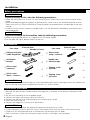 2
2
-
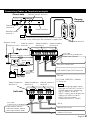 3
3
-
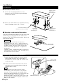 4
4
-
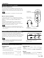 5
5
-
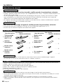 6
6
-
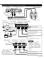 7
7
-
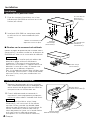 8
8
-
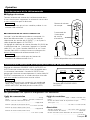 9
9
-
 10
10
-
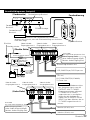 11
11
-
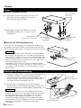 12
12
-
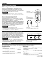 13
13
-
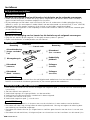 14
14
-
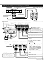 15
15
-
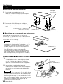 16
16
-
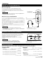 17
17
-
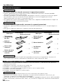 18
18
-
 19
19
-
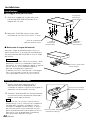 20
20
-
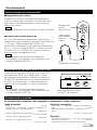 21
21
-
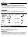 22
22
-
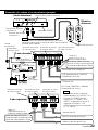 23
23
-
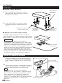 24
24
-
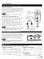 25
25
-
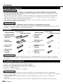 26
26
-
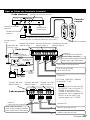 27
27
-
 28
28
-
 29
29
-
 30
30
-
 31
31
-
 32
32


Kenwood KVA-S300 El manual del propietario
- Tipo
- El manual del propietario
en otros idiomas
- français: Kenwood KVA-S300 Le manuel du propriétaire
- italiano: Kenwood KVA-S300 Manuale del proprietario
- English: Kenwood KVA-S300 Owner's manual
- Deutsch: Kenwood KVA-S300 Bedienungsanleitung
- Nederlands: Kenwood KVA-S300 de handleiding
- português: Kenwood KVA-S300 Manual do proprietário
Artículos relacionados
Otros documentos
-
 NAD Electronics S300 Manual de usuario
-
Yamaha DVX-S301 El manual del propietario
-
Pioneer AVHP6600DVD El manual del propietario
-
Pioneer AVH-P7500DVD El manual del propietario
-
Yamaha YRS-700 El manual del propietario
-
Pioneer Flat Panel Television PDP-42MVE1 Manual de usuario
-
Yamaha YRS-1100 El manual del propietario
-
