Ega Master 51249 El manual del propietario
- Categoría
- Medir, probar
- Tipo
- El manual del propietario

TESTER DE RESISTENCIA DE AISLAMIENTO
INSULATION RESISTANCE TESTER
ESPAÑOL ............................... 2
ENGLISH .............................. 10
GARANTIA / GUARANTEE ... 19
COD. 51249
MANUAL DE INSTRUCCIONES
OPERATING INSTRUCTIONS

2
INTRODUCCION
El medidor de resistencia de aislamiento modelo Cod. 51249 (de ahora en adelante “el
Medidor”), es un instrumento de mano diseñado principalmente para tomar mediciones de
resistencia/resistencia de aislamiento y tensión DC/AC.
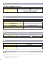
DESEMBALAJE
El Medidor incluye los siguientes artículos:
Tabla 1. Desembalaje
Artículo Descripción Cantidad
1 Instrucciones 1 libro
2 Cable de prueba 1 par
3 Sonda 1 par
4 Clip caimán 1 par
5 Bolsa 1 unidad
6 Correa 1 unidad
7 Batería 1.5V (LR14) 6 unidades
En caso de encontrar algún elemento dañado, por favor, póngase en contacto con su proveedor
de manera inmediata.
INFORMACION DE SEGURIDAD
Este medidor cumple con el requisito de las normas de seguridad IEC61010-1: en grado de
contaminación 2, categoría de sobretensión (CAT. III 600V, CAT.II 1000V) y doble aislamiento.
CAT. II: Nivel local, dispositivo, equipo portátil, etc., con menores sobretensiones transitorias
que CAT III.
CAT. III: Nivel de distribución, instalación ja, con menores sobretensiones transitorias que CAT. IV
Use el medidor sólo como se especica en este manual de instrucciones, de lo contrario la
protección provista por el instrumento podría verse afectada.
Peligro identica condiciones y acciones que pueden causar algún tipo de lesión al usuario.
Advertencia identica peligro de descarga eléctrica.
Precaución identica condiciones y acciones que pueden causar daños al Medidor durante
su uso.
Los símbolos internacionales eléctricos usados en el Medidor e indicados en este manual, son
explicados en la página 3.
ESPAÑOL

3
Peligro!
El uso del instrumento de un modo no especicado por el manual suministrado, puede causar
daños a elementos de seguridad y protección provistos en el equipo. Lea atentamente la siguiente
información acerca de la seguridad antes o durante el uso del instrumento.
- No aplique más de 1000V DC o 750V AC.
- No use el Medidor en entornos explosivos, de vapor o polvorientos.
- No use el medidor en un ambiente húmedo.
- Cuando haga uso de los cables de prueba, mantenga sus dedos lejos de las partes desnudas.
- Mantenga sus dedos detrás de los protectores.
- No utilice el Medidor si algún elemento o parte de caracasa están dañados o retirados.
- Cuando lleve a cabo mediciones de aislamiento, no toque el circuito bajo prueba.
Advertencia!
- No utilice el medidor si está dañado o alguna parte metálica queda expuesta. Asegúrese que el
medidor no posea golpes, grietas o partes plásticas defectuosas.
- Tenga cuidado cuando trabaje por encima de 30V rms, 46.7V ac rms y 70V DC. Tales voltages
pueden provocar daños por descargas.
- No cargue la batería cuando el Medidor se encuentre en un ambiente húmedo.
- Situe los cables de prueba en los terminales adecuados. Asegúrese que los cables de prueba
están rmemente conectados.
- Asegúrese de que el Medidor está apagado cuando abra el compartimento de la batería.
- Lea atentamente el manual de operación antes de utilizar el Medidor.
- Siga el manual de operaciones en todo momento durante el uso del Medidor y mantenga dicho
manual en un lugar seguro.
- Un mal uso puede causar un incidente o daños al Medidor.
Precaución!
- Cuando realice pruebas de resistencia, desconecte y descargue toda energía del circuito.
- Cuando de servicio al Medidor, utilice únicamente los cables de prueba o adaptadores del
mismo número de modelo o de idénticas especicaciones.
- No utilice el Medidor si el indicador de batería muestra ( ). Saque la batería del Medidor si
no va a ser utilizado durante un largo periodo de tiempo.
- No use o almacene el Medidor en un ambiente de alta temperatura, humedad, explosivo,
inamable y de fuertes campos magnéticos. El funcionamiento del Medidor puede ser dañado tras
ser humedecido.
SIMBOLOS ELECTRICOS INTERNACIONALES
Los símbolos eléctricos internacionales del Medidor y de este manual, son explicados en la
Tabla 2.
Tabla 2. Símbolos Eléctricos Internacionales
Equipo protejido por doble o reforzado aislamiento
DCV Medición DC
ACV Medición AC
Toma de tierra
Lea el Manual
Conforme a los Estándares de la Unión Europea

4
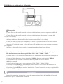
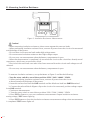
LA ESTRUCTURA DEL MEDIDOR
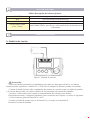
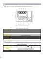
La Figura 1 y la Tabla 3 muestran la descripción de la estructura frontal del medidor.
Figura 1. Estructura frontal
Tabla 3. Descripción del frontal del Medidor
1 TIERRA: Resistencia terminal de entrada
2 G: Medición de tensión terminal de entrada negativo
3 V: Tensión terminal de entrada
4 LINEA: Resistencia terminal de entrada
5 LCD
6 Botón pantalla retroiluminada
7 Botón retención de datos
8 Botón resistencia de aislamiento
9 Selector giratorio
FUNCIONES DE LOS BOTONES
Tabla 4. Descripción de los botones
HOLD Presione una vez para activar retención de datos, el icono será mostrado
en la pantalla.
Presionelo nuevamente para desactivar la función de retención de datos, el
icono desaparecerá.
LIGHT Presione una vez para encender la retroiluminación.
Presionelo nuevamente para desactivar la retroiluminación.
TEST Presione para detener o comenzar la medición de resistencia de aislamiento.

5
SELECTOR GIRATORIO
Tabla 5.Descripción del selector giratorio
ON/OFF Apagar o encender el Medidor.
ACV Posición medición de tensión AC.
DCV Posición medición de tensión DC.
500V/1000V/2500V
(Cod. 51249 )
Posición para seleccionar la tensión de salida requerida:
500V/1000V/2500V, para llevar a cabo mediciónes de resistencia de
aislamiento.
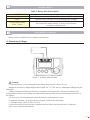
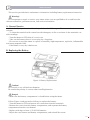
OPERACION DE MEDIDA
A. Medición de tensión
Figura 2. Medida de tensión
Precaución!
- Para evitar daños personales o al Medidor provocados por descargas eléctricas, no intente
medir tensiones superiores a 1000V DC o 750V rms AV aunque las lecturas puedan ser tomadas.
- Cuando la medición haya sido completada, desconecte la conexión entre los cables de prueba
y el circuito bajo prueba. Asi mismo retírelos de los terminales de entrada del Medidor.
- No lleve a cabo mediciones cuando el compartimento de la batería este abierto.
Para medir tensiones, congure el Medidor como se muestra en la Figura 2 y realice lo siguiente:
1. Gire el selector giratorio hasta DCV o ACV.
2. Inserte el cable de prueba rojo en el terminal V y el negro en el terminal G.
Proceda a la toma de medida.

6
B. Medición de resistencia de aislamiento
Figura 3. Medición de resistencia de aislamiento
Precaución!
- Cuando lleve a cabo mediciones de resistencia de aislamiento, por favor separe los cables de
prueba.
- Cuando lleve a cabo mediciones de resistencia de aislamiento, desconecte la energía del
circuito a ser medido.
- No cortocircuite los cables de prueba en ámbitos de alto voltaje.
- No haga mediciones de resistencia de aislamiento tras salidas de alto voltaje.
- Cuando la medición haya sido completada, no toque el circuito mientras el circuito continue
almacenando capacidad la cual puede provocar descargas eléctricas.
- No toque los cables de prueba, a pesar de haber sido retirados, hasta que se hayan descargado
por completo.
- No lleve a cabo mediciones cuando el compartimento de la batería este abierto.
Para medir resistencia de aislamiento, congure el Medidor según Figura 3 y haga lo siguiente:
-Gire el selector hasta una de estas posiciones: 250V / 500V / 1000V / 2500V.
1. Cuando lleve a cabo mediciones de resistencia de aislamiento, desconecte toda la energía del
circuito.
2. Inserte el cable de prueba rojo en el terminal LINEA y el negro en el terminal TIERRA.
3. Utilizando los clips caimán, conecte los cables de prueba al circuito a medir.
- Medición contínua
1. Gire el selector hasta una de estas posiciones: 250V / 500V / 1000V / 2500V
2. Presione el botón TEST para realizar mediciones contínuas. En la prueba de resistencia de
aislamiento, la luz del botón TEST se encenderá,
3. Presione el botón TEST para terminar la medición. Cuando la medición se haya completado la
luz del botón TEST se apagará.
MANTENIMIENTO
Esta sección suministra información a cerca del mantenimiento básico del Medidor incluyendo
instrucciones para la sustitución de la batería.

7
Advertencia!
No intente reparar o dar servicio al medidor a menos que esté calicado para hacerlo y tenga la
calibración correspondiente, pruebas de rendimiento e información de servicio.
A. Mantenimiento general
- Limpie periódicamente la carcasa con un paño húmedo y detergente. No utilice productos
abrasivos o disolventes.
- Para limpiar los terminales utilice una barra de algodón con detergente, ya que la suciedad o la
humedad en los terminales puede afectar a las lecturas.
- Apague el medidor en la posición OFF cuando no esté en uso.
- Saque la batería cuando no se utilice durante un periodo largo de tiempo.
- No utilice ni guarde el medidor en un ambientes húmedos, de temperaturas elevadas,
inamables, explosivos o fuertes campos magnéticos.
- Si el Medidor se ha humedecido, séquelo antes de su uso.
B. Sustitución de la batería
Figura 4. Sustitución de la batería
Precaución!
No mezcle baterías antiguas con baterías nuevas.
Preste atención a la polaridad cuando instale una batería.
Peligro!
- Asegurese de que el compartimento de la batería está debidamente cerrado antes de usar el
Medidor.
Observe la Figura 4 y proceda de la siguiente manera para sustituir la batería.
- Apague el Medidor y retire todas las conexiones de las entradas de los terminales.
- Retire el destornillador del compartimento de la batería y retire la carcasa del compartimento
de la batería.
- Sustituya las 6 baterías antiguas por unas nuevas baterías de 1.5V (LR14).
- Una de nuevo la tapa del compartimento de la batería y reinstale el tornillo.

8
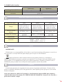
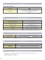
ESPECIFICACIONES
Seguridad y cumplimiento de normas
Certicación
Cumplimientos IEC 61010 -1 CAT.II 1000V, CAT.III 600V
sobrevoltaje y sobre aislamiento.
ESPECIFICACIONES FISICAS
Pantalla (LCD) Digital: 1999
Temperatura de operación 0 ~35 (32 ~95)
Temperatura de almacenamiento -20 ~60 (-4 ~140)
Humedad relativa 70% @ 0 ~35 por debajo;
80% @ -20 ~60
Tipo de batería 6unds de 1.5V (LR14)
Dimensiones (H x W x L) 150 x 100 x 71 mm
Peso Aprox. 0.5kg (incluyendo batería)
ESPECIFICACIONES GENERALES
Sobrecarga Muestra OL con sobrecarga en cada rango.
Indicador de batería Muestra
RESUMEN DE CARACTERISTICAS
Retroiluminación Retroiluminación para lecturas claras en entornos de escasa
luminosidad.
Autorango El Medidor selecciona automáticamente el mejor rango.
Advertencia La luz roja se encenderá cuando se trate con alto voltaje.
Tensión Auto descarga de tensión
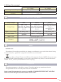
ESPECIFICACIONES DE PRECISION
Precisión:± ([a% de la lectura] + [numero de los dígitos menos signicantes]), garantía por 1
año.
Temperatura de operación: 18ºC ~28ºC
Humedad relativa: 45~75%RH

9
A. Medición de tensión
Tensión DC Tensión AC
Rango de medición ±30 ~ ±1000V 30V~750V (50/60Hz)
Resolución 1V
Precisión ±(2%+3)
MEDICION DE RESISTENCIA DE AISLAMIENTO
Tensión de salida 500V 1000V 2500V
Rango
3MΩ ~2GΩ
(menor que 3M, se
emite un sonido y
0MΩ será mostrado)
5MΩ ~4G
(menor que 5M, se
emite un sonido y
0MΩ será mostrado)
25M ~20G
(menor que 25M, se
emite un sonido
y 0MΩ será mostrado)
Tensión circuito
abierto DC500V±10% DC1000V±10% DC2500V±10%
Prueba de corriente 0.9mA~1.1mA
@500kΩ 0.9mA~1.1mA @1MΩ 0.9mA~1.1mA
@2.5MΩ
Cortocircuito En torno a menor que 1.8 mA
Precisión
3MΩ a 99.9MΩ : ± (3%+1)
100MΩ ~ 10GΩ : ± (5%+1)
10GΩ a 20GΩ : ± (10%+1)
NOTAS
IMPORTANTE!
El fabricante no se responsabiliza de los daños o mal funcionamiento del aparato en caso de un
uso incorrecto o se haya utilizado para trabajos para los que no está diseñado.
Según la directiva sobre residuos eléctricos de aparatos eléctricos y electrónicos
(WEEE), éstos deberán recogerse y tratarse por separado. Si en el futuro tiene que deshacerse de
este producto, no se deshaga de él junto con la basura doméstica. Póngase en contacto con su
distribuidor para proceder a su reciclaje de manera gratuita cuando sea posible.
GARANTÍA
El fabricante garantiza al comprador de este aparato la garantía total durante 12 meses de las
piezas con defectos de fabricación. Esta garantía no cubre aquellas piezas que por su uso normal
tienen un desgaste.
Nota: para obtener la validez de la garantía, es absolutamente imprescindible que complete y
remita al fabricante el documento de “CERTIFICADO DE GARANTIA”, dentro de los siete dias a
partir de la fecha de compra.

10
INTRODUCTION
The Model Cod. 51249 insulation resistance tester (hereafter, “the Meter”) is a handheld
instrument designed primarily to make resistance/ insulation resistance, DC/AC Voltage
measurement.
UNPACKING THE METER
The Meter includes the following items:
Table 1. Unpacking Inspection
Item Description Qty
1 English Operating Manual 1 piece
2 Test Lead 1 set
3 Test probe 1 set
4 Alligator clip 1 set
5 Carry bag 1 piece
6 Strap 1 piece
7 1.5V Battery (LR14) 6 pieces
In the event you nd any missing or damage, please contact your dealer immediately.
SAFETY INFORMATION
This Meter complies with the standards IEC61010 -1 safety measurement requirement: in
pollution degree 2, overvoltage category (CAT. III 600V, CAT.II 1000V) and double insulation.
CAT II: Local level, appliance, portable equipment etc., with smaller transient voltage
overvoltages than CAT. III
CAT III: Distribution level, xed installation, with smaller transient over voltages than
CAT. IV
Use the Meter only as specied in this operating manual, otherwise the protection provided by
the Meter may be impaired.
Danger identies conditions and actions that pose hazard(s) to the user.
Warning identies avoiding electric shock.
Caution identies conditions and actions that may damage the Meter and carrying out
accurate measurement.
International electrical symbols used on the Meter and in this Operating Manual are explained
on page 11.
ENGLISH

11
Danger!
Use of instrument in a manual not specied by the manufacturer may impair safety features/
protection provided by the equipment. Read the following safety information carefully before using
or servicing the instrument.
- Do not apply more than 1000V DC or 750V AC.
- Do not use the Meter around explosive gas, vapor or dust.
- Do not use the Meter in a wet environment.
- When using the test leads, keep your gures away from the lead contacts.
- Keep your gures behind the nger guards on the leads.
- Do not use the Meter with any parts or cover removed.
- When carrying out insulation measurement, do not contact the circuit under test.
Warning!
- Do not use the Meter if it is damaged or metal part is exposed. Look for cracks or missing
plastic.
- Be careful when working above 30V rms, 46.7V ac rms and 70V DC. Such voltages pose a
shock hazard.
- Do not change battery when the Meter is in wet environment.
- Place test leads in proper input terminals. Make sure all the test leads are rmly connected to
the Meters input terminals.
- Make sure the Meter is turned off when opening the battery compartment.
- Carefully read the operating manual before operating the Meter.
- Follow the operating manual all the time when using the Meter and keep the operating manual
in a safe place.
- Wrong operation will cause incident and damage to the Meter.
Caution!
- When performing resistance tests, remove all power from the circuit to be measured and
discharge all the power.
- When servicing the Meter, use only the same model number or identical electrical
specications of test leads and power adaptor.
- Do not use the Meter if the battery indicator ( ) shows a battery empty condition. Take the
battery out from the Meter if it is not used for a long time.
- Do not use or store the Meter in an environment of high temperature, humidity, explosive,
inammable and strong magnetic eld. The performance of the Meter may deteriorate after
dampened.
INTERNATIONAL ELECTRICAL SYMBOLS
International symbols on the Meter and in this manual are explained in Table 2.
Table 2. International Electrical Symbols
Equipment protected by double or reinforced insulation
DCV DC Measurement
ACV AC Measurement
Grounding
See Manual
Conforms to Standards of European Union

12
THE METER STRUCTURE
Below Figure 1 and Table 3 shows the Meter front structure and description.
Figure 1. The Meter Front Structure
Table 3. Meter Front Description
1 EARTH: Resistance input terminal
2 G: Voltage Measurement input negative terminal
3 V: Voltage input terminal
4 LINE: Resistance input terminal
5 LCD
6 Display Backlight button
7 Data Hold button
8 Insulation Resistance Button
9 Rotary switch
KEY FUNCTIONS
Table 4. Key Description
HOLD Press once to turn the data hold on, is shown on the display
Press again to turn the data hold feature off. is disappeared
LIGHT Press once to turn the display backlight on
Press again to turn the display backlight off
TEST Press to stop or start an insulation resistance test

13
ROTARY SWITCH
Table 5. Rotary Switch Description
ON/OFF Turn on or off the Meter
ACV Turn the rotary switch to ACV to measure AC Voltage
DCV Turn the rotary switch to DCV to measure DC Voltage
500V/1000V/2500V
(Cod. 51249 )
Turn the rotary switch to 500V/1000V/2500V, select
the requested output voltage, to carry out insulation
resistance measurement
MEASUREMENT OPERATION
Below section explains how to make measurements.
A. Measuring Voltages
Figure 2. Voltages Measurement
Caution!
- To avoid harm to you or damages to the Meter from electric shock, do not
Attempt to meaSure voltages higher than 1000V DC or 750V rms AC although readings may be
obtained.
- When voltage measurement has been completed, disconnect the connection between the
testing leads and the circuit under test and remove testing leads away from the input terminals of
the Meter.
- Do not carry out measurement when the battery compartment is open.
To measure voltages, set up the Meter as Figure 2 and do the following:
1. Turn the rotary switch to DCV or ACV.
2. Insert the red test lead into the V terminal and the black test lead into the G terminal.
Then carry out the measurement.

14
B. Measuring Insulation Resistance
Figure 3. Insulation Resistance Measurement
Caution!
- When measuring insulation resistance, please must separate the two test leads.
- When performing insulation resistance tests, remove all power from the circuit to be measured
and discharge all the power.
- Do not short circuit two test leads under high voltage status.
- Do not measure insulation resistance after high voltage output.
- Do not carry out measurement when the battery compartment is open.
- When the measurement is completed, do not touch the circuit as the circuit has already stored
capacitance, which may cause electric shock.
- Don’t touch the test leads even after it has been removed from the circuit until voltages are all
released.
- Do not carry out measurement when the battery compartment is open.
To measure insulation resistance, set up the Meter as Figure 3 and do the following:
- Turn the rotary switch to one of these position 250V / 500V / 1000V / 2500V.
1. When performing insulation resistance tests, remove all power from the circuit
to be measured and discharge all the power.
2. Insert the red test lead into the LINE terminal and the black test lead into EARTH terminal.
3. Connect the red and black alligator clip to the circuit to be measured, positive voltage output
from LINE terminal.
- Continuous Measurement
1. Turn the rotary switch to one of these position 250V / 500V / 1000V / 2500V
2. Press TEST to button to carry out continuous measurement. Output insulation resistance
testing voltage, TEST button light up,
3. Press TEST button to close the insulation resistance measurement voltage when measurement
is completed. TEST button lights off.

15
MAINTENANCE
This section provides basic maintenance information including battery replacement instruction.
Warning!
Do not attempt to repair or service your Meter unless you are qualied to do so and have the
relevant calibration, performance test, and service information.
A. General Service
- Periodically wipe the case with a damp cloth and mild detergent. Do not use abrasives or
solvents.
- To clean the terminals with cotton bar with detergent, as dirt or moisture in the terminals can
affect readings.
- Turn the Meter to OFF when it is not in use.
- Take out the battery when it is not using for a long time.
- Do not use or store the Meter in a place of humidity, high temperature, explosive, inammable
and strong magnetic eld.
- If the Meter is wet, dry it before use.
B. Replacing the Battery
Figure 4. Battery Replacement
Caution!
Do not mix to use old and new batteries.
Be careful the polarity is correct when installing batteries.
Danger!
- Make sure the battery compartment is closed before using the Meter
Follow Figure 4 and proceed as follows to replace the battery:
- Turn the Meter to OFF and remove all connections from the terminals.
- Remove the screw from the battery compartment, and separate the battery
compartment from the case bottom.
- Replace with 6pcs of new 1.5V (LR14) batteries.
- Rejoin the case bottom and battery compartment, and reinstall the screw.

16
SPECIFICATIONS
Safety and Compliances
Certication
Compliances
IEC 61010 -1 CAT.II 1000V, CAT.III 600V
overvoltage and double insulation
standard
PHYSICAL SPECIFICATIONS
Display (LCD) Digital: 1999 counts
Operating Temperature 0 ~35 (32 ~95)
Storage Temperature -20 ~60 (-4 ~140)
Relative Humidity 70% @ 0 ~35 below;
80% @ -20 ~60
Battery Type 6pcs of 1.5V (LR14) batteries
Dimensions (H x W x L) 150 x 100 x 71 mm
Weight Approx. 0.5kg (including battery)
GENERAL SPECIFICATIONS
Over loading Display OL when overload testing on every range
Battery Indicator Display
FEATURE SUMMARY
Display Backlight Bright backlight for clear readings in poorly lighted areas
Autorange The Meter automatically selects best range
Warning Red light will on when exporting high voltage
Voltage Auto release voltage
DETAILED ACCURACY SPECIFICATIONS
Accuracy:± ([a% of reading] + [number of least signicant digits]), guarantee for 1 year.
Operating temperature: 18ºC ~28ºC
Relative humidity: 45~75%RH

17
A. Voltage Measurement
DC Voltage AC Voltage
Measurement Range ±30 ~ ±1000V 30V~750V (50/60Hz)
Resolution 1V
Accuracy ±(2%+3)
INSULATION RESISTANCE MEASUREMENT
Output Voltage 500V 1000V 2500V
Display Range
3MΩ ~2GΩ
(less than 3M, buzzer
beeps and 0MΩ will be
shown)
5MΩ ~4G
(less than 5M, buzzer
beeps and 0MΩ will be
shown)
25M ~20G
(less than 25M, buzzer
beeps
and 0MΩ will be
shown)
Open Circuit Voltage DC500V±10% DC1000V±10% DC2500V±10%
Test Current 0.9mA~1.1mA
@500kΩ 0.9mA~1.1mA @1MΩ 0.9mA~1.1mA
@2.5MΩ
Short Circuit Around less than 1.8 mA
Accuracy
3MΩ to 99.9MΩ : ± (3%+1)
100MΩ ~ 10GΩ : ± (5%+1)
10GΩ to 20GΩ : ± (10%+1)
NOTES
IMPORTANT!
The maker will not take responsibility for damage or malfunction as a result of the device being
incorrectly used or, applied for a purpose for whith it was not intended.
According to Waste Electrical and Electronic Equipment directive (WEEE), these ones must
be collected and arranged separately. If you have to throw them out, please, do not use the usual
rubbish. Please, contact your distributor for free recycling.
GUARANTEE
The maker guarantees to the device owner 12 months against any manufacture defect.
This guarantee do not cover the parts wich are consumables.
Note: to apply the guarantee its necesary to send the “GUARANTEE CERTIFICATE” duly lled
within one week after purchased the machine to the maker.


-
 1
1
-
 2
2
-
 3
3
-
 4
4
-
 5
5
-
 6
6
-
 7
7
-
 8
8
-
 9
9
-
 10
10
-
 11
11
-
 12
12
-
 13
13
-
 14
14
-
 15
15
-
 16
16
-
 17
17
-
 18
18
-
 19
19
-
 20
20
-
 21
21
-
 22
22


Ega Master 51249 El manual del propietario
- Categoría
- Medir, probar
- Tipo
- El manual del propietario
en otros idiomas
- English: Ega Master 51249 Owner's manual
Otros documentos
-
Ideal Insulation Tester Instrucciones de operación
-
Ideal Insulation Tester Instrucciones de operación
-
Ideal 61-337 Manual de usuario
-
Amprobe AMB-45 Digital Megohmmeter Manual de usuario
-
Wavetek Meterman 220 Manual de usuario
-
-
-