Craftsman 117.205710 El manual del propietario
- Categoría
- Sistema de soldadura
- Tipo
- El manual del propietario

Operator’s Manual
210 AMP
MIG WELDER
Model No. 117.205710
CAUTION:
Before using welder, read this
manual and follow all its Safety
Rules and Operating Instructions.
Safety Rules
Installation
Operation
Maintenance
Parts
Español
Sears, Roebuck and Co., Hoffman Estates, IL 60179 U.S.A.
OM-194 199D April 2001
Visit the Craftsman web page: www.sears.com/craftsman

Effective January 1, 2000
Full One Year Warranty for Craftsman Welding Gun or Cables. For one year from the date
of purchase, when the welding gun or cables are operated and maintained according to
the owner’s manual instructions, if the welding gun or cables fail due to a defect in
material or workmanship, Sears will repair or replace the welding gun or cables free of
charge. This warranty does not cover parts consumed in normal operation, such as
contact tips, nozzles, gun liners, and drive rolls.
Full Three Year Warranty on Craftsman Welder. For three years from the date of
purchase, when the welder is operated and maintained according to the owner’s manual
instructions, if the welder fails due to a defect in material or workmanship, Sears will
repair or replace the welder free of charge. This warranty does not cover the welding gun,
cables, or normal consumable parts.
WARRANTY SERVICE IS AVAILABLE BY SIMPLY CONTACTING THE NEAREST
SEARS SERVICE CENTER. This warranty applies only while this product is in use in the
Untied States.
This warranty gives you specific legal rights, and you may have other rights which may
vary from state to state.
Sears Roebuck and Co., Dept.817WA, Hoffman Estates, IL 60179
brand_1yr_warr_1/00
Warranty On Welding Gun or Cables,
Welder, and Welder's Transformer
Model Name Serial/Style Number
Purchase Date (Date which equipment was delivered to original customer.)
Distributor
Address
City
State Zip
Please complete and retain with your personal records.
Owner’s Record

The following terms are
used interchangeably
throughout this manual:
MIG = GMAW
TABLE OF CONTENTS
WARRANTY
SECTION 1 – SAFETY PRECAUTIONS - READ BEFORE USING 1. . . . . . . . . . . . . . . . . . . . . . . . . . . .
1-1. Symbol Usage 1. . . . . . . . . . . . . . . . . . . . . . . . . . . . . . . . . . . . . . . . . . . . . . . . . . . . . . . . . . . . . . . .
1-2. Arc Welding Hazards 1. . . . . . . . . . . . . . . . . . . . . . . . . . . . . . . . . . . . . . . . . . . . . . . . . . . . . . . . . .
1-3. Additional Symbols for Installation, Operation, and Maintenance 3. . . . . . . . . . . . . . . . . . . . . .
1-4. Principal Safety Standards 3. . . . . . . . . . . . . . . . . . . . . . . . . . . . . . . . . . . . . . . . . . . . . . . . . . . . .
1-5. EMF Information 4. . . . . . . . . . . . . . . . . . . . . . . . . . . . . . . . . . . . . . . . . . . . . . . . . . . . . . . . . . . . . .
SECTION 2 – INSTALLATION 5. . . . . . . . . . . . . . . . . . . . . . . . . . . . . . . . . . . . . . . . . . . . . . . . . . . . . . . . . . .
2-1. Specifications 5. . . . . . . . . . . . . . . . . . . . . . . . . . . . . . . . . . . . . . . . . . . . . . . . . . . . . . . . . . . . . . . .
2-2. Volt-Ampere Curves 5. . . . . . . . . . . . . . . . . . . . . . . . . . . . . . . . . . . . . . . . . . . . . . . . . . . . . . . . . . .
2-3. Welding Power Source Duty Cycle And Overheating 6. . . . . . . . . . . . . . . . . . . . . . . . . . . . . . . .
2-4. Welding Gun Duty Cycle And Overheating 6. . . . . . . . . . . . . . . . . . . . . . . . . . . . . . . . . . . . . . . .
2-5. Installing Work Clamp 7. . . . . . . . . . . . . . . . . . . . . . . . . . . . . . . . . . . . . . . . . . . . . . . . . . . . . . . . . .
2-6. Installing Gas Supply 7. . . . . . . . . . . . . . . . . . . . . . . . . . . . . . . . . . . . . . . . . . . . . . . . . . . . . . . . . .
2-7. Installing Welding Gun 8. . . . . . . . . . . . . . . . . . . . . . . . . . . . . . . . . . . . . . . . . . . . . . . . . . . . . . . . .
2-8. Setting Gun Polarity 8. . . . . . . . . . . . . . . . . . . . . . . . . . . . . . . . . . . . . . . . . . . . . . . . . . . . . . . . . . .
2-9. Installing Wire Spool And Adjusting Hub Tension 9. . . . . . . . . . . . . . . . . . . . . . . . . . . . . . . . . . .
2-10. Changing Input Voltage 9. . . . . . . . . . . . . . . . . . . . . . . . . . . . . . . . . . . . . . . . . . . . . . . . . . . . . . . .
2-11. Electrical Service Guide 10. . . . . . . . . . . . . . . . . . . . . . . . . . . . . . . . . . . . . . . . . . . . . . . . . . . . . . . .
2-12. Selecting A Location And Connecting Input Power 10. . . . . . . . . . . . . . . . . . . . . . . . . . . . . . . . . .
2-13. Threading Welding Wire 11. . . . . . . . . . . . . . . . . . . . . . . . . . . . . . . . . . . . . . . . . . . . . . . . . . . . . . . .
2-14. Weld Parameter 12. . . . . . . . . . . . . . . . . . . . . . . . . . . . . . . . . . . . . . . . . . . . . . . . . . . . . . . . . . . . . .
2-15. Aluminum Weld Parameter For Use With Optional Spool Gun 13. . . . . . . . . . . . . . . . . . . . . . . .
SECTION 3 – OPERATION 14. . . . . . . . . . . . . . . . . . . . . . . . . . . . . . . . . . . . . . . . . . . . . . . . . . . . . . . . . . . . .
3-1. Front Panel Controls 14. . . . . . . . . . . . . . . . . . . . . . . . . . . . . . . . . . . . . . . . . . . . . . . . . . . . . . . . . . .
SECTION 4 – MAINTENANCE & TROUBLESHOOTING 15. . . . . . . . . . . . . . . . . . . . . . . . . . . . . . . . . . . .
4-1. Routine Maintenance 15. . . . . . . . . . . . . . . . . . . . . . . . . . . . . . . . . . . . . . . . . . . . . . . . . . . . . . . . . .
4-2. Circuit Breakers CB1 And CB2 15. . . . . . . . . . . . . . . . . . . . . . . . . . . . . . . . . . . . . . . . . . . . . . . . . .
4-3. Changing Drive Roll And Inlet Wire Guide 15. . . . . . . . . . . . . . . . . . . . . . . . . . . . . . . . . . . . . . . . .
4-4. Cleaning Or Replacing Gun Liner 16. . . . . . . . . . . . . . . . . . . . . . . . . . . . . . . . . . . . . . . . . . . . . . . .
4-5. Replacing Switch And/Or Head Tube 17. . . . . . . . . . . . . . . . . . . . . . . . . . . . . . . . . . . . . . . . . . . . .
4-6. Replacing Gun Contact Tip 18. . . . . . . . . . . . . . . . . . . . . . . . . . . . . . . . . . . . . . . . . . . . . . . . . . . . .
4-7. Troubleshooting 18. . . . . . . . . . . . . . . . . . . . . . . . . . . . . . . . . . . . . . . . . . . . . . . . . . . . . . . . . . . . . .
SECTION 5 – ELECTRICAL DIAGRAM 19. . . . . . . . . . . . . . . . . . . . . . . . . . . . . . . . . . . . . . . . . . . . . . . . . . .
SECTION 6 – MIG WELDING (GMAW) GUIDELINES 20. . . . . . . . . . . . . . . . . . . . . . . . . . . . . . . . . . . . . . .
6-1. Typical MIG Process Connections 20. . . . . . . . . . . . . . . . . . . . . . . . . . . . . . . . . . . . . . . . . . . . . . .
6-2. Typical MIG Process Control Settings 21. . . . . . . . . . . . . . . . . . . . . . . . . . . . . . . . . . . . . . . . . . . .
6-3. Holding And Positioning Welding Gun 22. . . . . . . . . . . . . . . . . . . . . . . . . . . . . . . . . . . . . . . . . . . .
6-4. Conditions That Affect Weld Bead Shape 23. . . . . . . . . . . . . . . . . . . . . . . . . . . . . . . . . . . . . . . . .
6-5. Gun Movement During Welding 24. . . . . . . . . . . . . . . . . . . . . . . . . . . . . . . . . . . . . . . . . . . . . . . . .
6-6. Poor Weld Bead Characteristics 24. . . . . . . . . . . . . . . . . . . . . . . . . . . . . . . . . . . . . . . . . . . . . . . . .
6-7. Good Weld Bead Characteristics 24. . . . . . . . . . . . . . . . . . . . . . . . . . . . . . . . . . . . . . . . . . . . . . . .
6-8. Troubleshooting – Excessive Spatter 25. . . . . . . . . . . . . . . . . . . . . . . . . . . . . . . . . . . . . . . . . . . . .
6-9. Troubleshooting – Porosity 25. . . . . . . . . . . . . . . . . . . . . . . . . . . . . . . . . . . . . . . . . . . . . . . . . . . . .
6-10. Troubleshooting – Excessive Penetration 26. . . . . . . . . . . . . . . . . . . . . . . . . . . . . . . . . . . . . . . . .
6-11. Troubleshooting – Lack Of Penetration 26. . . . . . . . . . . . . . . . . . . . . . . . . . . . . . . . . . . . . . . . . . .
6-12. Troubleshooting – Incomplete Fusion 26. . . . . . . . . . . . . . . . . . . . . . . . . . . . . . . . . . . . . . . . . . . . .
6-13. Troubleshooting – Burn-Through 27. . . . . . . . . . . . . . . . . . . . . . . . . . . . . . . . . . . . . . . . . . . . . . . . .
6-14. Troubleshooting – Waviness Of Bead 27. . . . . . . . . . . . . . . . . . . . . . . . . . . . . . . . . . . . . . . . . . . .
6-15. Troubleshooting – Distortion 27. . . . . . . . . . . . . . . . . . . . . . . . . . . . . . . . . . . . . . . . . . . . . . . . . . . .
6-16. Common MIG Shielding Gases 28. . . . . . . . . . . . . . . . . . . . . . . . . . . . . . . . . . . . . . . . . . . . . . . . . .
SECTION 7 – PARTS LIST 29. . . . . . . . . . . . . . . . . . . . . . . . . . . . . . . . . . . . . . . . . . . . . . . . . . . . . . . . . . . . . .
Español 35. . . . . . . . . . . . . . . . . . . . . . . . . . . . . . . . . . . . . . . . . . . . . . . . . . . . . . . . . . . . . . . . . . . . . . . . . . . . . .
OM-194 199D
WARNING
This product, when used
for welding or cutting,
produces fumes or
gases which contain
chemicals known to the
State of California to
cause birth defects and,
in some cases, cancer.
(California Health &
Safety Code Section
25249.5 et seq.)

OM-194 199 Page 1
SECTION 1 – SAFETY PRECAUTIONS - READ BEFORE USING
som _nd_4/98
1-1. Symbol Usage
Means Warning! Watch Out! There are possible hazards
with this procedure! The possible hazards are shown in
the adjoining symbols.
Y Marks a special safety message.
. Means “Note”; not safety related.
This group of symbols means Warning! Watch Out! possible
ELECTRIC SHOCK, MOVING PARTS, and HOT PARTS hazards.
Consult symbols and related instructions below for necessary actions
to avoid the hazards.
1-2. Arc Welding Hazards
Y The symbols shown below are used throughout this manual to
call attention to and identify possible hazards. When you see
the symbol, watch out, and follow the related instructions to
avoid the hazard. The safety information given below is only
a summary of the more complete safety information found in
the Safety Standards listed in Section 1-4. Read and follow all
Safety Standards.
Y Only qualified persons should install, operate, maintain, and
repair this unit.
Y During operation, keep everybody, especially children, away.
ELECTRIC SHOCK can kill.
Touching live electrical parts can cause fatal shocks
or severe burns. The electrode and work circuit is
electrically live whenever the output is on. The input
power circuit and machine internal circuits are also
live when power is on. In semiautomatic or automatic wire welding, the
wire, wire reel, drive roll housing, and all metal parts touching the
welding wire are electrically live. Incorrectly installed or improperly
grounded equipment is a hazard.
D Do not touch live electrical parts.
D Wear dry, hole-free insulating gloves and body protection.
D Insulate yourself from work and ground using dry insulating mats
or covers big enough to prevent any physical contact with the work
or ground.
D Do not use AC output in damp areas, if movement is confined, or if
there is a danger of falling.
D Use AC output ONLY if required for the welding process.
D If AC output is required, use remote output control if present on
unit.
D Disconnect input power or stop engine before installing or
servicing this equipment. Lockout/tagout input power according to
OSHA 29 CFR 1910.147 (see Safety Standards).
D Properly install and ground this equipment according to its
Owner’s Manual and national, state, and local codes.
D Always verify the supply ground – check and be sure that input
power cord ground wire is properly connected to ground terminal in
disconnect box or that cord plug is connected to a properly
grounded receptacle outlet.
D When making input connections, attach proper grounding conduc-
tor first – double-check connections.
D Frequently inspect input power cord for damage or bare wiring –
replace cord immediately if damaged – bare wiring can kill.
D Turn off all equipment when not in use.
D Do not use worn, damaged, undersized, or poorly spliced cables.
D Do not drape cables over your body.
D If earth grounding of the workpiece is required, ground it directly
with a separate cable.
D Do not touch electrode if you are in contact with the work, ground,
or another electrode from a different machine.
D Use only well-maintained equipment. Repair or replace damaged
parts at once. Maintain unit according to manual.
D Wear a safety harness if working above floor level.
D Keep all panels and covers securely in place.
D Clamp work cable with good metal-to-metal contact to workpiece
or worktable as near the weld as practical.
D Insulate work clamp when not connected to workpiece to prevent
contact with any metal object.
D Do not connect more than one electrode or work cable to any
single weld output terminal.
SIGNIFICANT DC VOLTAGE exists after removal of
input power on inverters.
D Turn Off inverter, disconnect input power, and discharge input
capacitors according to instructions in Maintenance Section
before touching any parts.
Welding produces fumes and gases. Breathing
these fumes and gases can be hazardous to your
health.
FUMES AND GASES can be hazardous.
D Keep your head out of the fumes. Do not breathe the fumes.
D If inside, ventilate the area and/or use exhaust at the arc to remove
welding fumes and gases.
D If ventilation is poor, use an approved air-supplied respirator.
D Read the Material Safety Data Sheets (MSDSs) and the
manufacturer’s instructions for metals, consumables, coatings,
cleaners, and degreasers.
D Work in a confined space only if it is well ventilated, or while
wearing an air-supplied respirator. Always have a trained watch-
person nearby. Welding fumes and gases can displace air and
lower the oxygen level causing injury or death. Be sure the breath-
ing air is safe.
D Do not weld in locations near degreasing, cleaning, or spraying op-
erations. The heat and rays of the arc can react with vapors to form
highly toxic and irritating gases.
D Do not weld on coated metals, such as galvanized, lead, or
cadmium plated steel, unless the coating is removed from the weld
area, the area is well ventilated, and if necessary, while wearing an
air-supplied respirator. The coatings and any metals containing
these elements can give off toxic fumes if welded.

OM-194 199 Page 2
Arc rays from the welding process produce intense
visible and invisible (ultraviolet and infrared) rays
that can burn eyes and skin. Sparks fly off from the
weld.
ARC RAYS can burn eyes and skin.
D Wear a welding helmet fitted with a proper shade of filter to protect
your face and eyes when welding or watching (see ANSI Z49.1
and Z87.1 listed in Safety Standards).
D Wear approved safety glasses with side shields under your
helmet.
D Use protective screens or barriers to protect others from flash and
glare; warn others not to watch the arc.
D Wear protective clothing made from durable, flame-resistant mate-
rial (leather and wool) and foot protection.
Welding on closed containers, such as tanks,
drums, or pipes, can cause them to blow up. Sparks
can fly off from the welding arc. The flying sparks, hot
workpiece, and hot equipment can cause fires and
burns. Accidental contact of electrode to metal objects can cause
sparks, explosion, overheating, or fire. Check and be sure the area is
safe before doing any welding.
WELDING can cause fire or explosion.
D Protect yourself and others from flying sparks and hot metal.
D Do not weld where flying sparks can strike flammable material.
D Remove all flammables within 35 ft (10.7 m) of the welding arc. If
this is not possible, tightly cover them with approved covers.
D Be alert that welding sparks and hot materials from welding can
easily go through small cracks and openings to adjacent areas.
D Watch for fire, and keep a fire extinguisher nearby.
D Be aware that welding on a ceiling, floor, bulkhead, or partition can
cause fire on the hidden side.
D Do not weld on closed containers such as tanks, drums, or pipes,
unless they are properly prepared according to AWS F4.1 (see
Safety Standards).
D Connect work cable to the work as close to the welding area as
practical to prevent welding current from traveling long, possibly
unknown paths and causing electric shock and fire hazards.
D Do not use welder to thaw frozen pipes.
D Remove stick electrode from holder or cut off welding wire at
contact tip when not in use.
D Wear oil-free protective garments such as leather gloves, heavy
shirt, cuffless trousers, high shoes, and a cap.
D Remove any combustibles, such as a butane lighter or matches,
from your person before doing any welding.
FLYING METAL can injure eyes.
D Welding, chipping, wire brushing, and grinding
cause sparks and flying metal. As welds cool,
they can throw off slag.
D Wear approved safety glasses with side
shields even under your welding helmet.
BUILDUP OF GAS can injure or kill.
D Shut off shielding gas supply when not in use.
D Always ventilate confined spaces or use
approved air-supplied respirator.
HOT PARTS can cause severe burns.
D Do not touch hot parts bare handed.
D Allow cooling period before working on gun or
torch.
MAGNETIC FIELDS can affect pacemakers.
D Pacemaker wearers keep away.
D Wearers should consult their doctor before
going near arc welding, gouging, or spot
welding operations.
NOISE can damage hearing.
Noise from some processes or equipment can
damage hearing.
D Wear approved ear protection if noise level is
high.
Shielding gas cylinders contain gas under high
pressure. If damaged, a cylinder can explode. Since
gas cylinders are normally part of the welding
process, be sure to treat them carefully.
CYLINDERS can explode if damaged.
D Protect compressed gas cylinders from excessive heat, mechani-
cal shocks, slag, open flames, sparks, and arcs.
D Install cylinders in an upright position by securing to a stationary
support or cylinder rack to prevent falling or tipping.
D Keep cylinders away from any welding or other electrical circuits.
D Never drape a welding torch over a gas cylinder.
D Never allow a welding electrode to touch any cylinder.
D Never weld on a pressurized cylinder – explosion will result.
D Use only correct shielding gas cylinders, regulators, hoses, and fit-
tings designed for the specific application; maintain them and
associated parts in good condition.
D Turn face away from valve outlet when opening cylinder valve.
D Keep protective cap in place over valve except when cylinder is in
use or connected for use.
D Read and follow instructions on compressed gas cylinders,
associated equipment, and CGA publication P-1 listed in Safety
Standards.

OM-194 199 Page 3
1-3. Additional Symbols For Installation, Operation, And Maintenance
FIRE OR EXPLOSION hazard.
D Do not install or place unit on, over, or near
combustible surfaces.
D Do not install unit near flammables.
D Do not overload building wiring – be sure power supply system is
properly sized, rated, and protected to handle this unit.
FALLING UNIT can cause injury.
D Use lifting eye to lift unit only, NOT running
gear, gas cylinders, or any other accessories.
D Use equipment of adequate capacity to lift and
support unit.
D If using lift forks to move unit, be sure forks are
long enough to extend beyond opposite side of
unit.
OVERUSE can cause OVERHEATING
D Allow cooling period; follow rated duty cycle.
D Reduce current or reduce duty cycle before
starting to weld again.
D Do not block or filter airflow to unit.
STATIC (ESD) can damage PC boards.
D Put on grounded wrist strap BEFORE handling
boards or parts.
D Use proper static-proof bags and boxes to
store, move, or ship PC boards.
MOVING PARTS can cause injury.
D Keep away from moving parts.
D Keep away from pinch points such as drive
rolls.
WELDING WIRE can cause injury.
D Do not press gun trigger until instructed to do
so.
D Do not point gun toward any part of the body,
other people, or any metal when threading
welding wire.
MOVING PARTS can cause injury.
D Keep away from moving parts such as fans.
D Keep all doors, panels, covers, and guards
closed and securely in place.
H.F. RADIATION can cause interference.
D High-frequency (H.F.) can interfere with radio
navigation, safety services, computers, and
communications equipment.
D Have only qualified persons familiar with
electronic equipment perform this installation.
D The user is responsible for having a qualified electrician prompt-
ly correct any interference problem resulting from the installa-
tion.
D If notified by the FCC about interference, stop using the
equipment at once.
D Have the installation regularly checked and maintained.
D Keep high-frequency source doors and panels tightly shut, keep
spark gaps at correct setting, and use grounding and shielding to
minimize the possibility of interference.
ARC WELDING can cause interference.
D Electromagnetic energy can interfere with
sensitive electronic equipment such as
computers and computer-driven equipment
such as robots.
D Be sure all equipment in the welding area is
electromagnetically compatible.
D To reduce possible interference, keep weld cables as short as
possible, close together, and down low, such as on the floor.
D Locate welding operation 100 meters from any sensitive elec-
tronic equipment.
D Be sure this welding machine is installed and grounded
according to this manual.
D If interference still occurs, the user must take extra measures
such as moving the welding machine, using shielded cables,
using line filters, or shielding the work area.
1-4. Principal Safety Standards
Safety in Welding and Cutting, ANSI Standard Z49.1, from American
Welding Society, 550 N.W. LeJeune Rd, Miami FL 33126
Safety and Health Standards, OSHA 29 CFR 1910, from Superinten-
dent of Documents, U.S. Government Printing Office, Washington, D.C.
20402.
Recommended Safe Practices for the Preparation for Welding and Cut-
ting of Containers That Have Held Hazardous Substances, American
Welding Society Standard AWS F4.1, from American Welding Society,
550 N.W. LeJeune Rd, Miami, FL 33126
National Electrical Code, NFPA Standard 70, from National Fire Protec-
tion Association, Batterymarch Park, Quincy, MA 02269.
Safe Handling of Compressed Gases in Cylinders, CGA Pamphlet P-1,
from Compressed Gas Association, 1235 Jefferson Davis Highway,
Suite 501, Arlington, VA 22202.
Code for Safety in Welding and Cutting, CSA Standard W117.2, from
Canadian Standards Association, Standards Sales, 178 Rexdale
Boulevard, Rexdale, Ontario, Canada M9W 1R3.
Safe Practices For Occupation And Educational Eye And Face
Protection, ANSI Standard Z87.1, from American National Standards
Institute, 1430 Broadway, New York, NY 10018.
Cutting And Welding Processes, NFPA Standard 51B, from National
Fire Protection Association, Batterymarch Park, Quincy, MA 02269.

OM-194 199 Page 4
1-5. EMF Information
Considerations About Welding And The Effects Of Low Frequency
Electric And Magnetic Fields
Welding current, as it flows through welding cables, will cause electro-
magnetic fields. There has been and still is some concern about such
fields. However, after examining more than 500 studies spanning 17
years of research, a special blue ribbon committee of the National
Research Council concluded that: “The body of evidence, in the
committee’s judgment, has not demonstrated that exposure to power-
frequency electric and magnetic fields is a human-health hazard.”
However, studies are still going forth and evidence continues to be
examined. Until the final conclusions of the research are reached, you
may wish to minimize your exposure to electromagnetic fields when
welding or cutting.
To reduce magnetic fields in the workplace, use the following
procedures:
1. Keep cables close together by twisting or taping them.
2. Arrange cables to one side and away from the operator.
3. Do not coil or drape cables around your body.
4. Keep welding power source and cables as far away from opera-
tor as practical.
5. Connect work clamp to workpiece as close to the weld as possi-
ble.
About Pacemakers:
Pacemaker wearers consult your doctor first. If cleared by your doctor,
then following the above procedures is recommended.

OM-194 199 Page 5
SECTION 2 – INSTALLATION
2-1. Specifications
Rated Welding
Output
Amperage
Range
Maximum
Open-Circuit
Voltage DC
Amperes Input at
Rated Load
Output, 60 Hz,
Single-Phase
Weight
Overall
Dimensions
Voltage DC
200 V 230 V KVA KW
150 A @ 23 Volts
DC, 60% Duty Cycle
30 – 185 33 30 (1.6)* 26 (1.4)* 6 (0.27)* 5 (0.13)*
165 lb
(75 kg)
Length: 36 in
(915 mm)
Width: 18 in
(457 mm)
Height: 27 in
(686 mm)
Wire Type And Diameter
Solid Steel /
Stainless
Steel
Flux Cored Aluminum
Calculated Wire Speed
Range At No Load
Max Wire Feed Speed
While Welding
.023 – .035 in
(0.6 - 0.9 mm)
.030 – .045 in
(0.8 – 1.2 mm)
.030 – .035 in
(0.8 – 0.9 mm)
138 – 795 IPM (3.5 – 20.3 m/min) 650 IPM (16.5 m/min)
*While idling
Operating Temperature Range – –20C to +40C Storage Temperature Range – -30C to + 50C
2-2. Volt-Ampere Curves
va_curve1 4/95 – SB-180 824
Volt-ampere curves show mini-
mum and maximum voltage and
amperage output capabilities of
unit. Curves of other settings fall be-
tween curves shown.

OM-194 199 Page 6
6 Minutes Welding 4 Minutes Resting
2-3. Welding Power Source Duty Cycle And Overheating
Duty Cycle is percentage of 10 min-
utes that unit can weld at rated load
without overheating.
If unit overheats, thermostat(s)
opens, output stops, and cooling
fan runs. Wait fifteen minutes for
unit to cool. Reduce amperage or
voltage, or duty cycle before
welding.
Y Exceeding duty cycle can
damage unit and void
warranty.
Overheating
0
15
A or V
OR
Reduce Duty Cycle
Minutes
duty1 4/95 – SB-181 009
60% Duty Cycle At 150 Amperes
2-4. Welding Gun Duty Cycle And Overheating
CAUTION
WELDING LONGER THAN RATED DUTY CYCLE can damage gun and void warranty.
• Do not weld at rated load longer than shown below.
• Using gasless flux cored wire reduces gun duty cycle.
warn7.1 8/93
Duty Cycle is percentage of 10
minutes that gun can weld at
rated load without overheating.
Continuous Welding
SB1.1 8/93
0
10
Minutes
Definition .023 To .045 in (0.6 To 1.1 mm)
Hard Or Flux Cored Wires
100% Duty Cycle At 150 Amperes
Using CO
2
100% Duty Cycle At 120 Amperes
Using Mixed Gases
.023 To .045 in (0.6 To 1.1 mm) Hard Or Flux Cored Wires
60% Duty Cycle At 200 Amperes
Using CO
2
60% Duty Cycle At 150 Amperes
Using Mixed Gases
6 Minutes Welding 4 Minutes Resting

OM-194 199 Page 7
2-5. Installing Work Clamp
1 Work Cable
2 Boot
Slide boot onto work cable. Route
cable out front panel opening from
inside.
3 Negative (–) Output Terminal
Connect cable to terminal and
cover connection with boot.
4 Hardware
5 Work Clamp
Route cable through clamp handle
and secure as shown.
Close door.
ST-801 566-A
1/2, 3/4 in
1
2
3
4
5
Tools Needed:
2-6. Installing Gas Supply
ST-801 571 / ST-802 028
Obtain gas cylinder and chain to
running gear, wall, or other station-
ary support so cylinder cannot fall
and break off valve.
1 Cap
2 Cylinder Valve
Remove cap, stand to side of valve,
and open valve slightly. Gas flow
blows dust and dirt from valve.
Close valve.
3 Cylinder
4 Regulator/Flowmeter
Install so face is vertical.
5 Regulator/Flowmeter Gas
Hose Connection
6 Welding Power Source Gas
Hose Connection
Connect customer supplied gas
hose between regulator/flowmeter
gas hose connection, and fitting on
rear of welding power source.
7 Flow Adjust
Typical flow rate is 20 cfh (cubic feet
per hour). Check wire manufactur-
er’s recommended flow rate.
8CO
2
Adapter (Customer Sup-
plied)
9 O-Ring (Customer Supplied)
Install adapter with O-ring between
regulator/flowmeter and CO
2
cylinder.
6
5/8, 1-1/8 in
Tools Needed:
CO
2
Gas
8 9
3
1
2
4
5
7
1
2
3
Argon Gas
OR

OM-194 199 Page 8
2-7. Installing Welding Gun
Ref. ST-801 567
1 Drive Assembly
2 Gun Securing Knob
3 Gun End
Loosen securing knob. Insert gun
end through opening until it bottoms
against drive assembly. Tighten
nut.
4 Gun Trigger Plug
Insert plug into receptacle, and
tighten threaded collar.
Close door.
2
1
3
4
2-8. Setting Gun Polarity
1 Polarity Changeover Label
Always read and follow manufac-
ture’s recommended polarity.
3/4, 11/16 in
Tools Needed:
Ref. 190 821-A
1

OM-194 199 Page 9
2-9. Installing Wire Spool And Adjusting Hub Tension
ST-072573-B
When a slight force is needed
to turn spool, tension is set.
15/16 in
Use compression spring with
8 in (200 mm) spools.
Tools Needed:
2-10. Changing Input Voltage
ST-801 580-A
Y Turn Off unit, and disconnect
input power.
Unit was shipped from factory set
for 230 volts.
1 Transformer T1
2 Rear Of Power Switch S1
3 Lead Marked 230 Volt And
Fan Motor Lead
Disconnect 230 volt lead and fan
motor lead from rear of S1. Leave
fan motor lead connected to 230
volt lead.
4 Lead Marked 200 Volt
Remove cable tie, and slide short
piece of sleeving off 200 volt lead,
and slide sleeving over end of 230
volt and fan motor leads. Fold
sleeving over and secure in place.
Connect 200 volt lead to S1 where
230 volt lead was removed.
Reinstall wrapper.
3/8, 7/16 in
1
Tools Needed:
2
3
4

OM-194 199 Page 10
2-11. Electrical Service Guide
Input Voltage 200 230
Input Amperes At Rated Output 30 26
Max Recommended Standard Fuse Or Circuit Breaker Rating In Amperes
Circuit Breaker
1
, Time-Delay
2
35 30
Normal Operating
3
45 40
Min Input Conductor Size In AWG/Kcmil 10 10
Max Recommended Input Conductor Length In Feet (Meters)
97
(29)
128
(39)
Min Grounding Conductor Size In AWG/Kcmil 10 10
Reference: 1999 National Electrical Code (NEC)
1 Choose a circuit breaker with time-current curves comparable to a Time Delay Fuse.
2 “Time-Delay” fuses are UL class “RK5” .
3 “Normal Operating” (general purpose – no intentional delay) fuses are UL class “K5” (up to and including 60 amp), and UL class “H” ( 65 amp and
above).
Y Caution: Failure to follow these fuse and circuit breaker recommendations could create an electric shock or fire hazard.
2-12. Selecting A Location And Connecting Input Power
1 Rating Label
Supply correct input power.
2 Plug
3 Receptacle
Connect plug to receptacle.
4 Input And Grounding
Conductors
Connect directly to line disconnect
device if hard wiring is required.
5 Line Disconnect Device
See Section 2-11.
Y Special installation may be
required where gasoline or
volatile liquids are present –
see NEC Article 511 or CEC
Section 20.
Ref. 801 568 / Ref. 800 797-C
L1
L2
230 VAC, 1
18 in (457 mm) of
space for airflow
L1
L2
1
Y Always connect grounding
conductor first.
= GND/PE
Y Do not move or operate unit
where it could tip.
4
2
3
1
5

OM-194 199 Page 11
2-13. Threading Welding Wire
Ref. ST-801 570-A / ST-801 083 / S-0627-A
6 in
(150 mm)
4 in
(102 mm)
WOOD
Open pressure assembly. Pull and hold wire; cut off end. Push wire thru guides into gun;
continue to hold wire.
Close and tighten pressure
assembly, and let go of wire.
Remove gun nozzle and contact tip. Turn On.
Press gun trigger until wire
comes out of gun. Reinstall
contact tip and nozzle.
Feed wire to check drive roll pressure.
Tighten knob enough to prevent slipping.
Cut off wire. Close
and latch door.
Tools Needed:
Tighten
1
2
3
4
. Use pressure indicator
scale to set a desired
drive roll pressure.
Pressure
Indicator
Scale
Tighten
1
2
3
4

OM-194 199 Page 12
2-14. Weld Parameter
Material Thickness
Wire Type,
Shielding Gas,
And Flow Rate
Wire
Diameter
(inch)
Operator
Controls
3/8 in
(9.5
mm)
1/4 in
(6.4
mm)
3/16 in
(4.8
mm)
1/8 in
(3.2
mm)
12 ga 14 ga 16 ga 18 ga 20 ga 22 ga
Voltage Tap – – 6 5 4 3 3 2 2 1 1
.023
Wire Speed – – 100 80 65 55 45 35 25 15 5
E70S-6
Voltage Tap 6 5 4 3 3 2 2 1 1 – –
CO
2
20 cfh+
.030
Wire Speed 80 70 60 55 45 35 25 15 5 – –
Voltage Tap 6 5 4 3 3 2 2 2 – – – –
.035
Wire Speed 70 60 50 45 40 30 20 10 – – – –
Voltage Tap – – 5 4 3 3 2 2 1 1 1
.023
Wire Speed – – 90 80 70 60 50 40 35 25 12
E70S-6
75% Argon
Voltage Tap 6 5 4 3 3 2 2 1 1 1
75% Argon
25% CO
2
20 cfh+
.030
Wire Speed 85 75 65 55 50 45 35 20 5 0
20 cfh+
Voltage Tap 6 5 4 3 3 2 2 1 1 – –
.035
Wire Speed 80 70 60 45 40 30 20 10 0 – –
Voltage Tap 6 5 5 4 4 3 2 1 – – – –
E71T-GS
.030
Wire Speed 80 70 65 55 50 30 20 10 – – – –
E71T-GS
Flux Core
Voltage Tap 6 5 4 3 3 2 1 – – – – – –
.035
Wire Speed 60 50 40 30 25 20 10 – – – – – –
Voltage Tap 5 4 4 4 3 3 3 2 2 2
.023
Wire Speed 95 85 80 60 50 50 50 30 20 20
ER 308
Stainless Steel
90% HE /
Voltage Tap 5 5 4 3 3 2 2 2 1 – –
90% HE /
7.5% Argon /
2.5% CO
2
.030
Wire Speed 70 70 70 50 45 50 45 40 0 – –
2
20 cfh+
Voltage Tap 6 5 5 4 3 2 2 2 – – – –
.035
Wire Speed 65 40 40 30 30 25 20 10 – – – –
*Do not change Voltage switch position while welding. Wire Speed is a starting value only, and can be adjusted while welding. Weld conditions also
depend on other variables such as stickout, travel speed, weld angle, cleanliness of metal, etc.

OM-194 199 Page 13
2-15. Aluminum Weld Parameter For Use With Optional Spool Gun
Wire Type, Wire
Material Thickness
Wire Type,
Shielding Gas,
And Flow Rate
Wire
Diameter
(inch)
Operator
Controls
3/8 in (9.5 mm) 1/4 in (6.4 mm)
3/16 in
(4.8 m m)
1/8 in (3.2 mm) 14 ga
Voltage Tap 5 5 4 3 2
4043 AL
.030
Wire Speed 88 88 73 55 45
4043 AL
100% Argon
Voltage Tap 6 6 5 4 2
.035
Wire Speed 95 85 68 59 34
Voltage Tap – 5 4 3 2
5356 AL
.030
Wire Speed – 100 90 80 70
5356 AL
100% Argon
Voltage Tap 6 6 5 4 2
.035
Wire Speed 100 92 85 70 60

OM-194 199 Page 14
SECTION 3 – OPERATION
3-1. Front Panel Controls
Ref. ST-180 930
Controls For Standard Units
1 Wire Speed Control
Use control to select a wire feed
speed. Scale around control is not
actual wire feed speed, but is for
reference only.
2 Voltage Switch
The higher the selected number,
the thicker the material that can be
welded (see Section 2-14). Do not
switch under load.
3 Power Switch
1
2
3

OM-194 199 Page 15
SECTION 4 – MAINTENANCE & TROUBLESHOOTING
4-1. Routine Maintenance
Y Disconnect power
before maintaining.
. Maintain more often
during severe conditions.
3 Months
Replace
Damaged Or
Unreadable
Labels
Clean And
Tighten
Weld
Terminals
Repair Or
Replace
Cracked
Cables And
Cords
6 Months
Blow Out Or
Vacuum Inside
Remove drive roll
and apply light coat
of oil or grease to
drive motor shaft.
4-2. Circuit Breakers CB1 And CB2
Ref. ST-801 567
Y Turn Off unit.
1 Circuit Breaker CB1
CB1 protects the transformer from
overload. If CB1 opens, wire
feeding stops.
2 Circuit Breaker CB2
CB2 protects the trigger circuit from
overload. If CB1 opens, weld output
stops.
Press button to reset circuit
breaker. Close door.
1
2
4-3. Changing Drive Roll And Inlet Wire Guide
Ref. ST-801 569-A
1 Drive Roll
Choose correct drive roll for wire
type, and install as shown.
2 Inlet Wire Guide
Remove guide by pressing on
barbed area, or cutting off one end
near housing and pulling it out of
hole. Push new guide into hole from
rear until it snaps in place.
Tools Needed:
2
1

OM-194 199 Page 16
4-4. Cleaning Or Replacing Gun Liner
Ref. ST-800 797-C
3/8 in
To Reassemble Gun:
Insert new liner.
Install and tighten wire outlet guide.
Cut liner off 3/4 in (20 mm) (3/8 in
[9.5 mm] for aluminum) from head
tube.
Install adapter, contact tip, and
nozzle.
Lay gun cable out straight
before installing new liner.
Head Tube
3/8 in
Remove liner.
Remove nozzle, contact tip, and
adapter.
Blow out gun casing.
Y Disconnect gun first.
Tools Needed:

OM-194 199 Page 17
4-5. Replacing Switch And/Or Head Tube
Ref. ST-800 795-C
1 Remove handle
locking nut.
2 Remove switch housing. Note: If installing new
switch, push switch lead connectors onto terminal of
new switch (polarity is not important). Install switch
back into handle, and secure with handle locking nut.
If replacing head tube, continue to end of figure.
3 Slide handle.
4 Secure head
tube in vice.
5 Loosen jam nut. Remove
from vice and turn head
tube out by hand.
6 Install existing shock washer onto
new head tube. Hand-tighten head
tube into connector cable.
7 Place head tube in vice and tighten
until nuts are tight.
8 Remove from vice. Reposition
handle and install switch housing.
Secure with handle locking nut.
Y Disconnect gun first.
3/4 in
Tools Needed:

OM-194 199 Page 18
4-6. Replacing Gun Contact Tip
Ref. 800 797-C
Y Turn Off unit.
1 Nozzle
2 Contact Tip
Cut off welding wire at contact tip.
Remove nozzle.
Remove contact tip and install new
contact tip. Reinstall nozzle.
1
2
Tools Needed:
4-7. Troubleshooting
Welding Trouble Remedy
No weld output; wire does not feed. Secure power cord plug in receptacle (see Section 2-12).
Check and replace power switch if necessary.
Check circuit breakers CB1 and/or CB2, and reset if necessary (see Section 4-2).
Replace building line fuse or reset circuit breaker if open (see Section 2-12).
Secure gun plug in receptacle or repair leads, or replace trigger switch (see Section 2-7 and/or 4-5).
Thermostat TP1 open (overheating). Allow fan to run; the thermostat will close when the unit has cooled
(see Section 2-3).
No weld output; wire feeds. Connect work clamp to get good metal to metal contact.
Replace contact tip (see Section 4-6).
Low weld output. Connect unit to proper input voltage or check for low line voltage (see Section 2-12).
Low, high, or erratic wire speed. Readjust front panel settings (see Section 3-1).
Change to correct size drive roll (see Section 11-3).
Readjust drive roll pressure (see Section 2-13).
Replace inlet guide, contact tip, and/or liner if necessary (see Sections 4-3, and 4-4).
Wire Drive/Gun Trouble Remedy
Electrode wire feeding stops during
Straighten gun cable and/or replace damaged parts (see Section 4-4).
welding.
Adjust drive roll pressure (see Section 2-13).
Readjust hub tension (see Section 2-9).
Replace contact tip if blocked (see Section 4-6).
Clean or replace wire inlet guide or liner if dirty or plugged (see Section 4-4).
Replace drive roll if worn or slipping (see Section 11-3).
Secure gun plug in receptacle or repair leads, or replace trigger switch (see Section 2-7 and/or 4-5).
Check and clear any restrictions at drive assembly and liner (see Section 4-4).
Have nearest Factory Authorized Service Agent check drive motor.

OM-194 199 Page 19
SECTION 5 – ELECTRICAL DIAGRAM
SB-186 065
Figure 5-1. Circuit Diagram

OM-194 199 Page 20
SECTION 6 – MIG WELDING (GMAW) GUIDELINES
6-1. Typical MIG Process Connections
Y Weld current can damage
electronic parts in vehicles.
Disconnect both battery
cables before welding on a
vehicle. Place work clamp as
close to the weld as possible.
light mig 5/967 / Ref. 801 909 / 801 570-B
Wire Feeder/
Power Source
Workpiece
Gun
Regulator/
Flowmeter
Gas
Shielding
Gas
Work Clamp

OM-194 199 Page 21
6-2. Typical MIG Process Control Settings
These settings are guidelines only. Material and wire type, joint design, fitup,
position, shielding gas, etc. affect settings. Test welds to be sure they comply to
specifications.
NOTE
1/8 or
.125 in
Material thickness determines weld
parameters.
Convert Material
(.001 in = 1 ampere)
.125 in = 125 A
Select Wire Size
Wire Size Amperage Range
.030 in
.035 in
.023 in
40 – 145 A
50 – 180 A
30 – 90 A
.035 in
Select Wire Speed
Select Voltage
Wire
Recommendation
.030 in
.035 in
.023 in
2 in per ampere
1.6 in per ampere
3.5 in per ampere
Wire Speed
2 x 125 A = 250 ipm
1.6 x 125 A = 200 ipm
3.5 x 125 A = 437 ipm
Set voltage midway between high/low voltage.
Low voltage: wire stubs into work
High voltage: arc is unstable (spatter)
125 A based on 1/8 in
Thickness to
(Amperage)
material thickness
Size (Approx.)
Amperage (A)
ipm = inch per minute
Ref. ST-801 865
Wire speed (amperage) controls weld pe-
netration (wire speed = burn-off rate)
Voltage controls height and width of
weld bead.

OM-194 199 Page 22
6-3. Holding And Positioning Welding Gun
Welding wire is energized when gun trigger is pressed. Before lowering helmet and
pressing trigger, be sure wire is no more than 1/2 in (13 mm) past end of nozzle,
and tip of wire is positioned correctly on seam.
NOTE
1 Hold Gun and Control Gun
Trigger
2 Workpiece
3 Work Clamp
4 Electrode Extension (Stickout)
1/4 to 1/2 in (6 To 13 mm)
5 Cradle Gun and Rest Hand on
Workpiece
2
3
5
4
90° 90°
0°-15°
45°
45°
GROOVE WELDS
FILLET WELDS
End View Of Work Angle Side View Of Gun Angle
End View Of Work Angle Side View Of Gun Angle
1
0°-15°
S-0421-A

OM-194 199 Page 23
6-4. Conditions That Affect Weld Bead Shape
Weld bead shape depends on gun angle, direction of travel, electrode extension
(stickout), travel speed, thickness of base metal, wire feed speed (weld current),
and voltage.
NOTE
Short Normal Long
Short Normal Long
10
°
10°
GUN ANGLES AND WELD BEAD PROFILES
ELECTRODE EXTENSIONS (STICKOUT)
FILLET WELD ELECTRODE EXTENSIONS (STICKOUT)
Push
Perpendicular Drag
GUN TRAVEL SPEED
Slow Normal Fast
S-0634

OM-194 199 Page 24
6-5. Gun Movement During Welding
Normally, a single stringer bead is satisfactory for most narrow groove weld joints;
however, for wide groove weld joints or bridging across gaps, a weave bead or
multiple stringer beads works better.
NOTE
1 Stringer Bead – Steady
Movement Along Seam
2 Weave Bead – Side To Side
Movement Along Seam
3 Weave Patterns
Use weave patterns to cover a wide
area in one pass of the electrode.
S-0054-A
3
1 2
6-6. Poor Weld Bead Characteristics
1 Large Spatter Deposits
2 Rough, Uneven Bead
3 Slight Crater During Welding
4 Bad Overlap
5 Poor Penetration
5
4
2
3
1
S-0053-A
6-7. Good Weld Bead Characteristics
1 Fine Spatter
2 Uniform Bead
3 Moderate Crater During
Welding
Weld a new bead or layer for each
1/8 in (3.2 mm) thickness in metals
being welded.
4 No Overlap
5 Good Penetration into Base
Metal
S-0052-B
2
3
1
4
5

OM-194 199 Page 25
6-8. Troubleshooting – Excessive Spatter
Excessive Spatter – scattering of molten metal particles that
cool to solid form near weld bead.
S-0636
Possible Causes Corrective Actions
Wire feed speed too high. Select lower wire feed speed.
Voltage too high. Select lower voltage range.
Electrode extension (stickout) too long. Use shorter electrode extension (stickout).
Workpiece dirty. Remove all grease, oil, moisture, rust, paint, undercoating, and dirt from work surface before welding.
Insufficient shielding gas at welding arc. Increase flow of shielding gas at regulator/flowmeter and/or prevent drafts near welding arc.
Dirty welding wire. Use clean, dry welding wire.
Eliminate pickup of oil or lubricant on welding wire from feeder or liner.
6-9. Troubleshooting – Porosity
Porosity – small cavities or holes resulting from gas pockets
in weld metal.
S-0635
Possible Causes Corrective Actions
Insufficient shielding gas at welding arc. Increase flow of shielding gas at regulator/flowmeter and/or prevent drafts near welding arc.
Remove spatter from gun nozzle.
Check gas hoses for leaks.
Place nozzle 1/4 to 1/2 in (6-13 mm) from workpiece.
Hold gun near bead at end of weld until molten metal solidifies.
Wrong gas. Use welding grade shielding gas; change to different gas.
Dirty welding wire. Use clean, dry welding wire.
Eliminate pick up of oil or lubricant on welding wire from feeder or liner.
Workpiece dirty. Remove all grease, oil, moisture, rust, paint, coatings, and dirt from work surface before welding.
Use a more highly deoxidizing welding wire (contact supplier).
Welding wire extends too far out of nozzle. Be sure welding wire extends not more than 1/2 in (13 mm) beyond nozzle.
6-10. Troubleshooting – Excessive Penetration
Good Penetration
Excessive Penetration – weld metal melting through base metal
and hanging underneath weld.
Excessive Penetration
S-0639
Possible Causes Corrective Actions
Excessive heat input. Select lower voltage range and reduce wire feed speed.
Increase travel speed.

OM-194 199 Page 26
6-11. Troubleshooting – Lack Of Penetration
Lack Of Penetration – shallow
fusion between weld metal and
base metal.
Lack of Penetration Good Penetration
S-0638
Possible Causes Corrective Actions
Improper joint preparation. Material too thick. Joint preparation and design must provide access to bottom of groove while
maintaining proper welding wire extension and arc characteristics.
Improper weld technique. Maintain normal gun angle of 0 to 15 degrees to achieve maximum penetration.
Keep arc on leading edge of weld puddle.
Be sure welding wire extends not more than 1/2 in (13 mm) beyond nozzle.
Insufficient heat input. Select higher wire feed speed and/or select higher voltage range.
Reduce travel speed.
6-12. Troubleshooting – Incomplete Fusion
Incomplete Fusion – failure of weld metal to fuse completely with
base metal or a preceeding weld bead.
S-0637
Possible Causes Corrective Actions
Workpiece dirty. Remove all grease, oil, moisture, rust, paint, undercoating, and dirt from work surface before
welding.
Insufficient heat input. Select higher voltage range and/or adjust wire feed speed.
Improper welding technique. Place stringer bead in proper location(s) at joint during welding.
Adjust work angle or widen groove to access bottom during welding.
Momentarily hold arc on groove side walls when using weaving technique.
Keep arc on leading edge of weld puddle.
Use correct gun angle of 0 to 15 degrees.
6-13. Troubleshooting – Burn-Through
Burn-Through – weld metal melting completely through base metal
resulting in holes where no metal remains.
S-0640
Possible Causes Corrective Actions
Excessive heat input. Select lower voltage range and reduce wire feed speed.
Increase and/or maintain steady travel speed.

OM-194 199 Page 27
6-14. Troubleshooting – Waviness Of Bead
Waviness Of Bead – weld metal that is not parallel and does not cover
joint formed by base metal.
S-0641
Possible Causes Corrective Actions
Welding wire extends too far out of nozzle. Be sure welding wire extends not more than 1/2 in (13 mm) beyond nozzle.
Unsteady hand. Support hand on solid surface or use two hands.
6-15. Troubleshooting – Distortion
Distortion – contraction of weld metal during welding that forces
base metal to move.
Base metal moves
in the direction of
the weld bead.
S-0642
Possible Causes Corrective Actions
Excessive heat input. Use restraint (clamp) to hold base metal in position.
Make tack welds along joint before starting welding operation.
Select lower voltage range and/or reduce wire feed speed.
Increase travel speed.
Weld in small segments and allow cooling between welds.

OM-194 199 Page 28
6-16. Common MIG Shielding Gases
This is a general chart for common gases and where they are used. Many different combinations (mixtures) of
shielding gases have been developed over the years. The most commonly used shielding gases are listed in the
following table.
Application
Gas
Spray Arc Steel Short Circuiting Steel
Short Circuiting
Stainless Steel
Short Circuiting
Aluminum
Argon All Positions
Argon + 25% CO
2
Flat & Horizontal
1
Fillet All Positions All Positions
2
CO
2
Flat & Horizontal
1
Fillet All Positions
Tri-Mix
3
All Positions
1 Globular Transfer
2 Single Pass Welding Only
3 90% HE + 7-1/2% AR + 2-1/2% CO
2

OM-194 199 Page 29
SECTION 7 – PARTS LIST–Welder Model No. 117.205710
ST-801 572-B
. * Standard hardware item –
may be purchased locally.
31
29
28
35
9
34
33
36
25
27
26
32
23
24
22
1
2
4 (Fig.7–2)
+
–
3
5
21
17
18
16
20
19
10
15
8
9
14
13
12
6
7
11
37
38
39
40
41
42
43
30
Figure 7-1. Main Assembly

OM-194 199 Page 30
Parts List–Welder Model No. 117.205710
Description
Part
No.
Dia.
Mkgs.
Item
No.
Figure 7-1. Main Assembly
Quantity
1 089 899 LATCH, slide flush 1. . . . . . . . . . . . . . . . . . . . . . . . . . . . . . . . . . . . . . . . . . . . . . . . . . . . . . . . . . . . . . . . .
2 134 464 LABEL, warning general precautionary 1. . . . . . . . . . . . . . . . . . . . . . . . . . . . . . . . . . . . . . . . . . . . . . .
3 +151 565 WRAPPER 1. . . . . . . . . . . . . . . . . . . . . . . . . . . . . . . . . . . . . . . . . . . . . . . . . . . . . . . . . . . . . . . . . . . . . .
4 Fig 7-2 CENTER BAFFLE, w/components 1. . . . . . . . . . . . . . . . . . . . . . . . . . . . . . . . . . . . . . . . . . . . . . . . . . . .
5 SR1 191 487 RECTIFIER ASSEMBLY, (consisting of) 1. . . . . . . . . . . . . . . . . . . . . . . . . . . . . . . . . . . . . . . .
180 920 BRACKET RECTIFIER 1. . . . . . . . . . . . . . . . . . . . . . . . . . . . . . . . . . . . . . . . . . . . . . . . . . . . . . . . . . . . . . . .
191 375 RECTIFIER SI DIODE ASSEMBLY, POS 1. . . . . . . . . . . . . . . . . . . . . . . . . . . . . . . . . . . . . . . . . . . . . . . .
191 376 RECTIFIER SI DIODE ASSEMBLY, NEG 1. . . . . . . . . . . . . . . . . . . . . . . . . . . . . . . . . . . . . . . . . . . . . . . .
152 862 GROMMET, SCR .250 panel hole 8. . . . . . . . . . . . . . . . . . . . . . . . . . . . . . . . . . . . . . . . . . . . . . . . . . . . . . .
026 947 STAND-OFF 2. . . . . . . . . . . . . . . . . . . . . . . . . . . . . . . . . . . . . . . . . . . . . . . . . . . . . . . . . . . . . . . . . . . . . . . . .
TP1 604 515 THERMOSTAT, NC open 211F 1. . . . . . . . . . . . . . . . . . . . . . . . . . . . . . . . . . . . . . . . . . . . . . . . . . .
6 FM 123 468 MOTOR, fan 230V 60/50 Hz 3000RPM 1. . . . . . . . . . . . . . . . . . . . . . . . . . . . . . . . . . . . . . . . . . .
7 005 656 BLADE, fan 6.000 4wg 30 deg .175 bore 1. . . . . . . . . . . . . . . . . . . . . . . . . . . . . . . . . . . . . . . . . . . . . .
8 180 918 PANEL, rear 1. . . . . . . . . . . . . . . . . . . . . . . . . . . . . . . . . . . . . . . . . . . . . . . . . . . . . . . . . . . . . . . . . . . . . .
9 190 773 BEZEL, front rear 2. . . . . . . . . . . . . . . . . . . . . . . . . . . . . . . . . . . . . . . . . . . . . . . . . . . . . . . . . . . . . . . . .
10 180 923 BRACKET, bottle retainer 1. . . . . . . . . . . . . . . . . . . . . . . . . . . . . . . . . . . . . . . . . . . . . . . . . . . . . . . . . . .
11 602 387 CHAIN, weldless 2/0 x 27 1. . . . . . . . . . . . . . . . . . . . . . . . . . . . . . . . . . . . . . . . . . . . . . . . . . . . . . . . . .
12 605 227 NUT, 750-14 knurled 1.68dia 1. . . . . . . . . . . . . . . . . . . . . . . . . . . . . . . . . . . . . . . . . . . . . . . . . . . . . . . .
13 PLG1 181 072 CORD SET, 250V 6-50P 12ga 3/c 1. . . . . . . . . . . . . . . . . . . . . . . . . . . . . . . . . . . . . . . . . . . . .
14 111 443 BUSHING, strain relief 1. . . . . . . . . . . . . . . . . . . . . . . . . . . . . . . . . . . . . . . . . . . . . . . . . . . . . . . . . . . . . .
15 GS1 125 785 VALVE, 24VAC 2 way 1. . . . . . . . . . . . . . . . . . . . . . . . . . . . . . . . . . . . . . . . . . . . . . . . . . . . . . . .
16 180 916 BASE 1. . . . . . . . . . . . . . . . . . . . . . . . . . . . . . . . . . . . . . . . . . . . . . . . . . . . . . . . . . . . . . . . . . . . . . . . . . . .
17 147 893 AXLE, running gear 1. . . . . . . . . . . . . . . . . . . . . . . . . . . . . . . . . . . . . . . . . . . . . . . . . . . . . . . . . . . . . . . .
18 186 758 WHEEL, rubolene 10in dia x 2.25 2. . . . . . . . . . . . . . . . . . . . . . . . . . . . . . . . . . . . . . . . . . . . . . . . . . . .
19 602 250 WASHER, flat .812 ID x 1.469 OD 4. . . . . . . . . . . . . . . . . . . . . . . . . . . . . . . . . . . . . . . . . . . . . . . . . . .
20 121 614 RING, rtng ext .750 shaft 2. . . . . . . . . . . . . . . . . . . . . . . . . . . . . . . . . . . . . . . . . . . . . . . . . . . . . . . . . . .
21 Z **180 989 STABILIZER 1. . . . . . . . . . . . . . . . . . . . . . . . . . . . . . . . . . . . . . . . . . . . . . . . . . . . . . . . . . . . . . . . . . .
TP2 163 266 THERMOSTAT, NC 1. . . . . . . . . . . . . . . . . . . . . . . . . . . . . . . . . . . . . . . . . . . . . . . . . . . . . . . . . . . . .
22 008 999 CASTER, swvl 4.00 in plastic 2. . . . . . . . . . . . . . . . . . . . . . . . . . . . . . . . . . . . . . . . . . . . . . . . . . . . . . .
23 T1 180 925 TRANSFORMER, power main 1. . . . . . . . . . . . . . . . . . . . . . . . . . . . . . . . . . . . . . . . . . . . . . . . . .
24 180 924 PANEL, side lower 1. . . . . . . . . . . . . . . . . . . . . . . . . . . . . . . . . . . . . . . . . . . . . . . . . . . . . . . . . . . . . . . . .
25 S2 153 197 SWITCH, selector 6 position 1. . . . . . . . . . . . . . . . . . . . . . . . . . . . . . . . . . . . . . . . . . . . . . . . . . . .
26 RC2 048 282 RECEPTACLE W/SOCKETS 1. . . . . . . . . . . . . . . . . . . . . . . . . . . . . . . . . . . . . . . . . . . . . . . . .
27 S1 124 511 SWITCH, tgl DPST 40A 600VAC scr 1. . . . . . . . . . . . . . . . . . . . . . . . . . . . . . . . . . . . . . . . . . . . . .
28 180 917 PANEL, front 1. . . . . . . . . . . . . . . . . . . . . . . . . . . . . . . . . . . . . . . . . . . . . . . . . . . . . . . . . . . . . . . . . . . . .
29 148 956 HANDLE, switch 1. . . . . . . . . . . . . . . . . . . . . . . . . . . . . . . . . . . . . . . . . . . . . . . . . . . . . . . . . . . . . . . . . .
30 057 357 BUSHING, snap-in nyl .937 ID x 1.125mtg hole 2. . . . . . . . . . . . . . . . . . . . . . . . . . . . . . . . . . . . . . .
31 097 924 KNOB, pointer 1. . . . . . . . . . . . . . . . . . . . . . . . . . . . . . . . . . . . . . . . . . . . . . . . . . . . . . . . . . . . . . . . . . . .
32 R1 035 897 POTENTIOMETER 1. . . . . . . . . . . . . . . . . . . . . . . . . . . . . . . . . . . . . . . . . . . . . . . . . . . . . . . . . . . .
33 NAMEPLATE, (order by model and serial number) 1. . . . . . . . . . . . . . . . . . . . . . . . . . . . . . . . . . . . . . . . . . . . . .
34 147 571 HANDLE 1. . . . . . . . . . . . . . . . . . . . . . . . . . . . . . . . . . . . . . . . . . . . . . . . . . . . . . . . . . . . . . . . . . . . . . . . .
35 130 750 CLAMP, work 300A 1. . . . . . . . . . . . . . . . . . . . . . . . . . . . . . . . . . . . . . . . . . . . . . . . . . . . . . . . . . . . . . . .
36 600 318 CABLE, weld copper (order by ft) 10ft. . . . . . . . . . . . . . . . . . . . . . . . . . . . . . . . . . . . . . . . . . . . . . . . . . .
165 745 HOUSING & PINS 2. . . . . . . . . . . . . . . . . . . . . . . . . . . . . . . . . . . . . . . . . . . . . . . . . . . . . . . . . . . . . . . . . . . .
192 121 REGULATOR/FLOWMETER, 10–50 cfh 1. . . . . . . . . . . . . . . . . . . . . . . . . . . . . . . . . . . . . . . . . . . . . . . . .
144 108 HOSE, gas 5ft 1. . . . . . . . . . . . . . . . . . . . . . . . . . . . . . . . . . . . . . . . . . . . . . . . . . . . . . . . . . . . . . . . . . . . . . .
37 *SCREW, 008-15 x .37 hexwhd-pln stl 13. . . . . . . . . . . . . . . . . . . . . . . . . . . . . . . . . . . . . . . . . . . . . . . . . . . . . . . .
38 *NUT, 375-16 .56 hex stl 2. . . . . . . . . . . . . . . . . . . . . . . . . . . . . . . . . . . . . . . . . . . . . . . . . . . . . . . . . . . . . . . . . . . .
39 *RIVET, al .187 dia x .063 - .125 5. . . . . . . . . . . . . . . . . . . . . . . . . . . . . . . . . . . . . . . . . . . . . . . . . . . . . . . . . . . . . .
40 *RIVET, al .125 dia x .188 - .250 4. . . . . . . . . . . . . . . . . . . . . . . . . . . . . . . . . . . . . . . . . . . . . . . . . . . . . . . . . . . . . .
41 *SCREW, k50 x 20 soc hd-trx stl pl 4. . . . . . . . . . . . . . . . . . . . . . . . . . . . . . . . . . . . . . . . . . . . . . . . . . . . . . . . . . .
42 *NUT, 375-32 .56 hex stl 1. . . . . . . . . . . . . . . . . . . . . . . . . . . . . . . . . . . . . . . . . . . . . . . . . . . . . . . . . . . . . . . . . . . .
43 *NUT, 312-18 .56 hex stl 2. . . . . . . . . . . . . . . . . . . . . . . . . . . . . . . . . . . . . . . . . . . . . . . . . . . . . . . . . . . . . . . . . . . .
*Standard hardware item – may be purchased locally.
+When ordering a component originally displaying a precautionary label, the label should also be ordered.
**When ordering stabilizer 180 989, also order thermostat 163 266.
To maintain the factory original performance of your equipment, use only Manufacturer’s Suggested
Replacement Parts. Model number required when ordering parts from a Sears Parts/Repair Center.

OM-194 199 Page 31
Parts List–Welder Model No. 117.205710
Figure 7-2. Center Baffle w/Components
ST-801 631-D
. * Standard hardware item –
may be purchased locally.
Fig.7–4 – 28
27
24
7
8
2
3
5
4
1
6
22
21
23
18
17
14
16
13
20
9
15
12
11
10
29
30
31
33
32
25
26
36
34
35
37
Description
Part
No.
Item
No.
Figure 7-2. Baffle, Center w/Components (Fig 7-1 Item 4)
Quantity
Dia.
Mkgs.
1 058 427 RING, retaining spool 1. . . . . . . . . . . . . . . . . . . . . . . . . . . . . . . . . . . . . . . . . . . . . . . . . . . . . . . . . . . . . .
2 085 980 NUT, 625-11 .94 hex 1. . . . . . . . . . . . . . . . . . . . . . . . . . . . . . . . . . . . . . . . . . . . . . . . . . . . . . . . . . . . . .
3 605 941 WASHER, flat 1. . . . . . . . . . . . . . . . . . . . . . . . . . . . . . . . . . . . . . . . . . . . . . . . . . . . . . . . . . . . . . . . . . . . .
4 186 437 SPRING, cprsn .84500 x .110W 1. . . . . . . . . . . . . . . . . . . . . . . . . . . . . . . . . . . . . . . . . . . . . . . . . . . . .
5 057 971 WASHER, flat .632 ID x 1.500 OD x .12 1. . . . . . . . . . . . . . . . . . . . . . . . . . . . . . . . . . . . . . . . . . . . . .
6 057 745 SPRING, cprsn 2.430 OD x .90 wire x 2.500 1. . . . . . . . . . . . . . . . . . . . . . . . . . . . . . . . . . . . . . . . . .
7 186 435 HUB, spool 1. . . . . . . . . . . . . . . . . . . . . . . . . . . . . . . . . . . . . . . . . . . . . . . . . . . . . . . . . . . . . . . . . . . . . . .
8 186 436 WASHER, brake plastic 1. . . . . . . . . . . . . . . . . . . . . . . . . . . . . . . . . . . . . . . . . . . . . . . . . . . . . . . . . . . .
9 180 915 BAFFLE, center 1. . . . . . . . . . . . . . . . . . . . . . . . . . . . . . . . . . . . . . . . . . . . . . . . . . . . . . . . . . . . . . . . . . .
10 C6 191 385 CAPACITOR ASSEMBLY, (consisting of) 1. . . . . . . . . . . . . . . . . . . . . . . . . . . . . . . . . . . . . . . . .
11 191 374 CAPACITOR, elctlt 30000uf 4. . . . . . . . . . . . . . . . . . . . . . . . . . . . . . . . . . . . . . . . . . . . . . . . . . . . . . . . .
12 191 101 BUSS BAR, positive 1. . . . . . . . . . . . . . . . . . . . . . . . . . . . . . . . . . . . . . . . . . . . . . . . . . . . . . . . . . . . . . .
13 191 102 BUSS BAR, negative 1. . . . . . . . . . . . . . . . . . . . . . . . . . . . . . . . . . . . . . . . . . . . . . . . . . . . . . . . . . . . . . .
14 188 846 SCREW, .010-32 x .50 hex hd-slt S 8. . . . . . . . . . . . . . . . . . . . . . . . . . . . . . . . . . . . . . . . . . . . . . . . . .

OM-194 199 Page 32
Parts List–Welder Model No. 117.205710
Description
Part
No.
Item
No.
Figure 7-2. Baffle, Center w/Components (Continued) (Fig 7-1 Item 4)
Quantity
Dia.
Mkgs.
15 083 147 GROMMET, scr No. 8/10 panel hole 4. . . . . . . . . . . . . . . . . . . . . . . . . . . . . . . . . . . . . . . . . . . . . . . . .
16 180 927 REEL SUPPORT 1. . . . . . . . . . . . . . . . . . . . . . . . . . . . . . . . . . . . . . . . . . . . . . . . . . . . . . . . . . . . . . . . . .
17 057 358 BUSHING, snap-in nyl 1.000 ID x 1.375mtg hole 1. . . . . . . . . . . . . . . . . . . . . . . . . . . . . . . . . . . . . .
18 R2 091 685 RESISTOR, WW fxd 50W 1. . . . . . . . . . . . . . . . . . . . . . . . . . . . . . . . . . . . . . . . . . . . . . . . . . . . . .
20 W 189 486 CONTACTOR, def prp 40A 3P 1. . . . . . . . . . . . . . . . . . . . . . . . . . . . . . . . . . . . . . . . . . . . . . . . . .
21 PC1 171 986 CIRCUIT CARD ASSEMBLY, control 1. . . . . . . . . . . . . . . . . . . . . . . . . . . . . . . . . . . . . . . . . . .
22 134 201 STAND-OFF SUPPORT, PC card 4. . . . . . . . . . . . . . . . . . . . . . . . . . . . . . . . . . . . . . . . . . . . . . . . . . .
23 CB1 183 492 CIRCUIT BREAKER, man reset 10A 250V 1. . . . . . . . . . . . . . . . . . . . . . . . . . . . . . . . . . . . . .
24 CB2 180 912 CIRCUIT BREAKER, man reset 5A 250V 1. . . . . . . . . . . . . . . . . . . . . . . . . . . . . . . . . . . . . . .
25 097 421 TERMINAL, pwr output red 1. . . . . . . . . . . . . . . . . . . . . . . . . . . . . . . . . . . . . . . . . . . . . . . . . . . . . . . . .
26 097 416 TERMINAL, pwr output black 1. . . . . . . . . . . . . . . . . . . . . . . . . . . . . . . . . . . . . . . . . . . . . . . . . . . . . . .
27 CR1 072 817 RELAY, encl 24VAC DPDT 20 1. . . . . . . . . . . . . . . . . . . . . . . . . . . . . . . . . . . . . . . . . . . . . . . . .
28 Fig 7-4 DRIVE ASSEMBLY, wire 1. . . . . . . . . . . . . . . . . . . . . . . . . . . . . . . . . . . . . . . . . . . . . . . . . . . . . . . . . . . .
PLG3 115 093 CONNECTOR & SOCKETS 1. . . . . . . . . . . . . . . . . . . . . . . . . . . . . . . . . . . . . . . . . . . . . . . . . . . . . .
RC3 131 059 CONNECTOR & PINS 1. . . . . . . . . . . . . . . . . . . . . . . . . . . . . . . . . . . . . . . . . . . . . . . . . . . . . . . . . .
29 *SCREW, 250-20 x .62 hex hd 7. . . . . . . . . . . . . . . . . . . . . . . . . . . . . . . . . . . . . . . . . . . . . . . . . . . . . . . . . . . . . . .
30 *RIVET, al .125 dia x .188-.250 3. . . . . . . . . . . . . . . . . . . . . . . . . . . . . . . . . . . . . . . . . . . . . . . . . . . . . . . . . . . . . . .
31 *RIVET, al .187 dia x .157-.472 1. . . . . . . . . . . . . . . . . . . . . . . . . . . . . . . . . . . . . . . . . . . . . . . . . . . . . . . . . . . . . . .
32 *SCREW, .250-20 X 1.00 hexwhd 2. . . . . . . . . . . . . . . . . . . . . . . . . . . . . . . . . . . . . . . . . . . . . . . . . . . . . . . . . . . .
33 *SCREW, k 40 x 12 pan hd-phl stl 4. . . . . . . . . . . . . . . . . . . . . . . . . . . . . . . . . . . . . . . . . . . . . . . . . . . . . . . . . . . .
34 *SCREW, .250-20 x .50 hexwhd 20. . . . . . . . . . . . . . . . . . . . . . . . . . . . . . . . . . . . . . . . . . . . . . . . . . . . . . . . . . . . . .
35 *NUT, .250-20 .44 hex 11. . . . . . . . . . . . . . . . . . . . . . . . . . . . . . . . . . . . . . . . . . . . . . . . . . . . . . . . . . . . . . . . . . . . . .
36 *NUT, .500-13 .75 hex 2. . . . . . . . . . . . . . . . . . . . . . . . . . . . . . . . . . . . . . . . . . . . . . . . . . . . . . . . . . . . . . . . . . . . . .
37 *BOLT, crg stl .250-20 x .750 4. . . . . . . . . . . . . . . . . . . . . . . . . . . . . . . . . . . . . . . . . . . . . . . . . . . . . . . . . . . . . . . . .
196 894 BRACKET, consumable/tool tray 1. . . . . . . . . . . . . . . . . . . . . . . . . . . . . . . . . . . . . . . . . . . . . . . . . . . . . . .
202 449 PLATE, switch 1. . . . . . . . . . . . . . . . . . . . . . . . . . . . . . . . . . . . . . . . . . . . . . . . . . . . . . . . . . . . . . . . . . . . . . .
*Standard hardware item – may be purchased locally.
To maintain the factory original performance of your equipment, use only Manufacturer’s Suggested
Replacement Parts. Model number required when ordering parts from a Sears Parts/Repair Center.

OM-194 199 Page 33
Parts List–Welder Model No. 117.205710
Figure 7-3. M-15 Gun
800 792-B
8
9
10
14
17
11
12
11
12
13
9
15
16
1
2
3
5
To maintain the factory original performance of your equipment, use only Manufacturer’s Suggested
Replacement Parts. Model number required when ordering parts from a Sears Parts /Repair Center.
Description Quantity
Part
No.
169 589
Item
No.
Figure 7-3. M-15 Gun (Fig 7-1 Item 36)
1 169 715 NOZZLE, slip type .500 orf flush 1. . . . . . . . . . . . . . . . . . . . . . . . . . . . . . . . . . . . . . . . . . . . . . . . . . . . .
2 ♦087 299 TIP, contact scr .023 wire x 1.125. . . . . . . .
2 ♦000 067 TIP, contact scr .030 wire x 1.125. . . . . . . .
2 ♦000 068 TIP, contact scr .035 wire x 1.125. . . . . . . .
2 ♦000 069 TIP, contact scr .045 wire x 1.125. . . . . . . .
3 169 716 ADAPTER, contact tip 1. . . . . . . . . . . . . . . . . . . . . . . . . . . . . . . . . . . . . . . . . . . . . . . . . . . . . . . . . . . . . .
5 170 470 RING, retaining 1. . . . . . . . . . . . . . . . . . . . . . . . . . . . . . . . . . . . . . . . . . . . . . . . . . . . . . . . . . . . . . . . . . . .
8 169 718 TUBE, head 1. . . . . . . . . . . . . . . . . . . . . . . . . . . . . . . . . . . . . . . . . . . . . . . . . . . . . . . . . . . . . . . . . . . . . . .
9 169 738 NUT, locking handle 2. . . . . . . . . . . . . . . . . . . . . . . . . . . . . . . . . . . . . . . . . . . . . . . . . . . . . . . . . . . . . . . .
10 194 524 NUT, jam 1. . . . . . . . . . . . . . . . . . . . . . . . . . . . . . . . . . . . . . . . . . . . . . . . . . . . . . . . . . . . . . . . . . . . . . . . .
11 169 737 HANDLE 2. . . . . . . . . . . . . . . . . . . . . . . . . . . . . . . . . . . . . . . . . . . . . . . . . . . . . . . . . . . . . . . . . . . . . . . . . .
12 169 741 STRAIN RELIEF, cable 2. . . . . . . . . . . . . . . . . . . . . . . . . . . . . . . . . . . . . . . . . . . . . . . . . . . . . . . . . . . . .
13 180 433 CORD, trigger assembly 1. . . . . . . . . . . . . . . . . . . . . . . . . . . . . . . . . . . . . . . . . . . . . . . . . . . . . . . . . . . .
14 079 974 O-RING, .500 ID x .103CS rbr 2. . . . . . . . . . . . . . . . . . . . . . . . . . . . . . . . . . . . . . . . . . . . . . . . . . . . . . .
15 ♦194 010 LINER, monocoil .023/.025 wire x 15ft (consisting of) 1. . . . . . . . . . . . . . . . . . . . . . . . . . . . . . . . .
15 ♦194 011 LINER, monocoil .030/.035 wire x 15ft (consisting of) 1. . . . . . . . . . . . . . . . . . . . . . . . . . . . . . . . .
15 ♦194 012 LINER, monocoil .035/.045 wire x 15ft (consisting of) 1. . . . . . . . . . . . . . . . . . . . . . . . . . . . . . . . .
16 079 975 O-RING, .187 ID x .103CS rbr 1. . . . . . . . . . . . . . . . . . . . . . . . . . . . . . . . . . . . . . . . . . . . . . . . . . . . . . .
17 196 255 SWITCH, trigger 1. . . . . . . . . . . . . . . . . . . . . . . . . . . . . . . . . . . . . . . . . . . . . . . . . . . . . . . . . . . . . . . . . . .
♦Optional

OM-194 199 Page 34
Parts List–Welder Model No. 117.205710
Description
Part
No.
Item
No.
Figure 7-4. Drive Assembly, Wire (Fig 7-2 Item 29)
Quantity
1 196 237 MOTOR, gear 24VDC 1. . . . . . . . . . . . . . . . . . . . . . . . . . . . . . . . . . . . . . . . . . . . . . . . . . . . . . . . . . . . . .
2 180 929 HOUSING, motor drive 1. . . . . . . . . . . . . . . . . . . . . . . . . . . . . . . . . . . . . . . . . . . . . . . . . . . . . . . . . . . . .
3 198 789 DRIVE ASSEMBLY, wire (consisting of) 1. . . . . . . . . . . . . . . . . . . . . . . . . . . . . . . . . . . . . . . . . . . . . .
4 196 895 KNOB, adjustment tension 1. . . . . . . . . . . . . . . . . . . . . . . . . . . . . . . . . . . . . . . . . . . . . . . . . . . . . . . . . .
5 090 415 SPRING, cprsn .695 OD x .080 wire x 1.500 1. . . . . . . . . . . . . . . . . . . . . . . . . . . . . . . . . . . . . . . . . .
6 198 080 CUP, spring 185 1. . . . . . . . . . . . . . . . . . . . . . . . . . . . . . . . . . . . . . . . . . . . . . . . . . . . . . . . . . . . . . . . . . .
7 085 242 FASTENER, pinned 1. . . . . . . . . . . . . . . . . . . . . . . . . . . . . . . . . . . . . . . . . . . . . . . . . . . . . . . . . . . . . . . .
8 090 416 PIN, hinge 1. . . . . . . . . . . . . . . . . . . . . . . . . . . . . . . . . . . . . . . . . . . . . . . . . . . . . . . . . . . . . . . . . . . . . . . .
9 124 817 HOUSING, wire drive 1. . . . . . . . . . . . . . . . . . . . . . . . . . . . . . . . . . . . . . . . . . . . . . . . . . . . . . . . . . . . . .
10 090 443 BEARING, ball rdl sgl row .315 x .866 x .27 (consisting of) 1. . . . . . . . . . . . . . . . . . . . . . . . . . . . . .
111 622 SPACER, bearing .196 ID x .310 OD x .500 collar 1. . . . . . . . . . . . . . . . . . . . . . . . . . . . . . . . . . . . . . . . . .
11 112 031 LEVER, pressure roll 1. . . . . . . . . . . . . . . . . . . . . . . . . . . . . . . . . . . . . . . . . . . . . . . . . . . . . . . . . . . . . . . .
12 151 828 PIN, cotter hair .054 x .750 1. . . . . . . . . . . . . . . . . . . . . . . . . . . . . . . . . . . . . . . . . . . . . . . . . . . . . . . . . .
13 124 778 KNOB, T 2.000 bar w/.312-18 st 1. . . . . . . . . . . . . . . . . . . . . . . . . . . . . . . . . . . . . . . . . . . . . . . . . . . . .
14 174 609 SCREW 3. . . . . . . . . . . . . . . . . . . . . . . . . . . . . . . . . . . . . . . . . . . . . . . . . . . . . . . . . . . . . . . . . . . . . . . . . .
15 090 423 ROLL, drive V groove .023-.035 1. . . . . . . . . . . . . . . . . . . . . . . . . . . . . . . . . . . . . . . . . . . . . . . . . . . . .
16 058 549 GUIDE, wire inlet 1/16 1. . . . . . . . . . . . . . . . . . . . . . . . . . . . . . . . . . . . . . . . . . . . . . . . . . . . . . . . . . . . .
17 010 224 PIN, spring CS .187 x 1.000 1. . . . . . . . . . . . . . . . . . . . . . . . . . . . . . . . . . . . . . . . . . . . . . . . . . . . . . . .
18 *SCREW, m 6-1.0 x 20 soc hd button 3. . . . . . . . . . . . . . . . . . . . . . . . . . . . . . . . . . . . . . . . . . . . . . . . . . . . . . . . .
19 *WASHER, tooth .195 ID x .410 OD 3. . . . . . . . . . . . . . . . . . . . . . . . . . . . . . . . . . . . . . . . . . . . . . . . . . . . . . . . . .
20 *NUT, .010-32 .38 hex 3. . . . . . . . . . . . . . . . . . . . . . . . . . . . . . . . . . . . . . . . . . . . . . . . . . . . . . . . . . . . . . . . . . . . . .
21 *WASHER, flat .344 ID x .688 OD 1. . . . . . . . . . . . . . . . . . . . . . . . . . . . . . . . . . . . . . . . . . . . . . . . . . . . . . . . . . . .
22 *WASHER, lock .168 ID x .277 OD 1. . . . . . . . . . . . . . . . . . . . . . . . . . . . . . . . . . . . . . . . . . . . . . . . . . . . . . . . . . .
23 *SCREW, .010-32 x .87 hexwhd 2. . . . . . . . . . . . . . . . . . . . . . . . . . . . . . . . . . . . . . . . . . . . . . . . . . . . . . . . . . . . . .
1
ST-181 053-A
2
4
3
5
6
7
8
9
10
11
12
Includes
Items
13, 16, 17
13
14
15
16
17
. Hardware is common and
not available unless listed.
18
19
20
23
21
22
Figure 7-4. Drive Assembly, Wire
*Standard hardware item – may be purchased locally.
To maintain the factory original performance of your equipment, use only Manufacturer’s Suggested
Replacement Parts. Model number required when ordering parts from a Sears Parts /Repair Center.

OM-194 199 Page 35
Notes

OM-194 199 Página 36
Efectiva 1 enero, 2000
Garantía de un año para las antorchas o cables Craftsman. Por todo un año a partir de la
fecha de compra, cuando se ha operado y se ha mantenido la antorcha y los cables de
acuerdo a las instrucciones del manual del operador. Si la antorcha o los cables fallan
debido a un defecto en material o mano de obra, Sears reparará o reemplazará la
antorcha de soldar o los cables sin costo. Esta garantía no cubre piezas consumibles que
se consumen en operación normal, tales como tubos de contacto, boquillas, forros
internos del alambre o rodillos de alimentación.
Garantía de tres años para la soldadora Craftsman. Por tres años desde la fecha de
compra, cuando se le ha operado y mantenido a la soldadora de acuerdo a las
instrucciones en el manual del operador, si la soldadora falla debido a un defecto en
material o mano de obra, Sears reparará o reemplazará la soldadora sin costo. Esta
garantía no cubre la antorcha de soldar, los cables o las piezas consumibles normales.
SERVICIO DE GARANTÍA ESTÁ DISPONIBLE SIMPLEMENTE HACIENDO
CONTACTO CON EL CENTRO DE SERVICIO DE SEARS MÁS CERCANO. Esta
garantía aplica solamente mientras se usa el producto en los Estados Unidos.
Esta garantía le da derechos legales específicos, y usted puede tener otros derechos
que varían de estado a estado.
Sears Roebuck and Co., Dept.817WA, Hoffman Estates, IL60179
Garantía para la antorcha de soldar o
cables, soldadora y el transformador de
la soldadora
Nombre de modelo Número de serie/estilo
Fecha de compra (Fecha en que el equipo era entregado al cliente original.)
Distribuidor
Dirección
Cuidad
Estado/PaísCódigo postal
Por favor complete y retenga con sus archivos.
Archivo de Dueño

Los terminos siguientes
se usan de una forma
intercambiable a lo largo
de este manual:
MIG = GMAW
INDICE
GARANTIA
SECCION 8 – PRECAUCIONES DE SEGURIDAD – LEA ANTES DE USAR 37. . . . . . . . . . . . . . . . . . .
8-1. Uso de Símbolos 37. . . . . . . . . . . . . . . . . . . . . . . . . . . . . . . . . . . . . . . . . . . . . . . . . . . . . . . . . . . . .
8-2. Peligros en Soldadura de Arco 37. . . . . . . . . . . . . . . . . . . . . . . . . . . . . . . . . . . . . . . . . . . . . . . . . .
8-3. Símbolos Adicionales para Instalación, Operación y Mantenimiento 39. . . . . . . . . . . . . . . . . . .
8-4. Estándares Principales de Seguridad 39. . . . . . . . . . . . . . . . . . . . . . . . . . . . . . . . . . . . . . . . . . . . .
8-5. Información del EMF 40. . . . . . . . . . . . . . . . . . . . . . . . . . . . . . . . . . . . . . . . . . . . . . . . . . . . . . . . . .
SECCION 9 – INSTALACION 41. . . . . . . . . . . . . . . . . . . . . . . . . . . . . . . . . . . . . . . . . . . . . . . . . . . . . . . . . . .
9-1. Especificaciones 41. . . . . . . . . . . . . . . . . . . . . . . . . . . . . . . . . . . . . . . . . . . . . . . . . . . . . . . . . . . . . .
9-2. Curvas Voltio-Amperio 41. . . . . . . . . . . . . . . . . . . . . . . . . . . . . . . . . . . . . . . . . . . . . . . . . . . . . . . . .
9-3. Ciclo de trabajo de la Fuente de Poder de Soldadura y el sobrecalentamiento 42. . . . . . . . . . .
9-4. Ciclo de trabajo de la antorcha y el sobrecalentamiento 42. . . . . . . . . . . . . . . . . . . . . . . . . . . . .
9-5. Instalando la Grampa de Trabajo 43. . . . . . . . . . . . . . . . . . . . . . . . . . . . . . . . . . . . . . . . . . . . . . . .
9-6. Instalando el Gas Protectivo 43. . . . . . . . . . . . . . . . . . . . . . . . . . . . . . . . . . . . . . . . . . . . . . . . . . . .
9-7. Instalando la Pistola 44. . . . . . . . . . . . . . . . . . . . . . . . . . . . . . . . . . . . . . . . . . . . . . . . . . . . . . . . . . .
9-8. Fijando la Polaridad de la Pistola 44. . . . . . . . . . . . . . . . . . . . . . . . . . . . . . . . . . . . . . . . . . . . . . . .
9-9. Instalando el Carrete de Alambre y Ajuste de la Tensión del Eje 45. . . . . . . . . . . . . . . . . . . . . . .
9-10. Cambiando el Voltaje de Entrada 45. . . . . . . . . . . . . . . . . . . . . . . . . . . . . . . . . . . . . . . . . . . . . . . .
9-11. Guía de Servicio Eléctrico 46. . . . . . . . . . . . . . . . . . . . . . . . . . . . . . . . . . . . . . . . . . . . . . . . . . . . . .
9-12. Seleccionando Una Ubicación y Conectando la Potencia de Entrada 46. . . . . . . . . . . . . . . . . .
9-13. Enhilando el Alambre de Soldadura 47. . . . . . . . . . . . . . . . . . . . . . . . . . . . . . . . . . . . . . . . . . . . . .
9-14. Parámetro de Soldadura 48. . . . . . . . . . . . . . . . . . . . . . . . . . . . . . . . . . . . . . . . . . . . . . . . . . . . . . .
9-15. Parámetros de Soldar con Alumínio para el Uso Opcional del Spoolmate 185 49. . . . . . . . . . .
SECCION 10 – OPERACION 50. . . . . . . . . . . . . . . . . . . . . . . . . . . . . . . . . . . . . . . . . . . . . . . . . . . . . . . . . . . .
10-1. Controles del Panel Frontal 50. . . . . . . . . . . . . . . . . . . . . . . . . . . . . . . . . . . . . . . . . . . . . . . . . . . . .
SECCION 11 – MANTENIMIENTO Y CORRECCION DE AVERIAS 51. . . . . . . . . . . . . . . . . . . . . . . . . . .
11-1. Mantención Rutinario 51. . . . . . . . . . . . . . . . . . . . . . . . . . . . . . . . . . . . . . . . . . . . . . . . . . . . . . . . . .
11-2. Bréiquers CB1 y CB2 51. . . . . . . . . . . . . . . . . . . . . . . . . . . . . . . . . . . . . . . . . . . . . . . . . . . . . . . . . .
11-3. Instalando los Rodillo de Alimentación y Guía de Alambre 51. . . . . . . . . . . . . . . . . . . . . . . . . . .
11-4. Limpiando o Reemplazando el Forro Interno del Cable de la Pistola 52. . . . . . . . . . . . . . . . . . .
11-5. Reemplazando el Interruptor y/o Tubo Cabezal 53. . . . . . . . . . . . . . . . . . . . . . . . . . . . . . . . . . . .
11-6. Reemplazando el Tubo de Contacto de la Pistola 54. . . . . . . . . . . . . . . . . . . . . . . . . . . . . . . . . . .
11-7. Corrección de Averías 54. . . . . . . . . . . . . . . . . . . . . . . . . . . . . . . . . . . . . . . . . . . . . . . . . . . . . . . . .
SECCION 12 – DIAGRAMAS ELECTRICOS 55. . . . . . . . . . . . . . . . . . . . . . . . . . . . . . . . . . . . . . . . . . . . . .
SECCION 13 – DIRECTIVAS PARA SOLDADURA MIG (GMAW) 56. . . . . . . . . . . . . . . . . . . . . . . . . . . . .
13-1. Conexiones Típicas para el Proceso MIG 56. . . . . . . . . . . . . . . . . . . . . . . . . . . . . . . . . . . . . . . . .
13-2. Fijaciones de Control para un Proceso de MIG Típico 57. . . . . . . . . . . . . . . . . . . . . . . . . . . . . . .
13-3. Como Sostener y Posicionar la Pistola de Soldar 58. . . . . . . . . . . . . . . . . . . . . . . . . . . . . . . . . . .
13-4. Condiciones que Afectan la Forma del Cordón de Suelda 59. . . . . . . . . . . . . . . . . . . . . . . . . . . .
13-5. Movimiento de la Pistola durante la Suelda 60. . . . . . . . . . . . . . . . . . . . . . . . . . . . . . . . . . . . . . . .
13-6. Características Malas de un Cordón de Soldadura 60. . . . . . . . . . . . . . . . . . . . . . . . . . . . . . . . . .
13-7. Características Buenas de un Cordón de Soldadura 60. . . . . . . . . . . . . . . . . . . . . . . . . . . . . . . .
13-8. Soluciones a Problemas de Soldadura – Excesiva Salpicadura 61. . . . . . . . . . . . . . . . . . . . . . .
13-9. Soluciones a Problemas de Soldadura – Porosidad 61. . . . . . . . . . . . . . . . . . . . . . . . . . . . . . . . .
13-10. Soluciones a Problemas de Soldadura – Penetración Excesiva 62. . . . . . . . . . . . . . . . . . . .
13-11. Soluciones a Problemas de Soldadura – Falta de Penetración62. . . . . . . . . . . . . . . . . . . . .
13-12. Soluciones a Problemas de Soldadura – Fusión Incompleta 62. . . . . . . . . . . . . . . . . . . . . . .
13-13. Soluciones a Problemas de Soldadura – Hacer Hueco 63. . . . . . . . . . . . . . . . . . . . . . . . . . .
13-14. Soluciones a Problemas de Soldadura – Cordón en forma de Olas 63. . . . . . . . . . . . . . . . .
13-15. Soluciones a Problemas de Soldadura – Distorción63. . . . . . . . . . . . . . . . . . . . . . . . . . . . . .
13-16. Gases Más Comunes para Protección de Soldadura MIG 64. . . . . . . . . . . . . . . . . . . . . . . . .
OM-194 199 Página 37
ADVERTENCIA
Este producto cuando se
usa para soldar o cortar,
produce humo o gases
que contienen químicos
conocidos en el estado
de California por causar
defectos al feto y en
algunos casos, cáncer.
(Sección de Seguridad
del Código de Salud en
California No. 25249.5 y
lo que sigue)

OM-194 199 Página 38
SECCION 8 – PRECAUCIONES DE SEGURIDAD – LEA ANTES DE USAR
som _nd_spa 4/98
8-1. Uso de Símbolos
Significa ¡Precaución! ¡Cuidado! ¡Hay peligros posibles
con este procedimiento! Los peligros posibles se mues-
tra en los símbolos anexos.
Y Anota un mensaje especial de seguridad.
. Significa NOTESE; no relacionado con seguridad.
Este grupo de símbolos significa ¡Precaución! ¡Cuidado! peligros
posibles de CHOQUE ELECTRICO, PARTES MOVIBLES, y
PARTES CALIENTES. Consulte a los símbolos y instrucciones
relacionados abajo para las acciones necesarias para evitar los
peligros.
8-2. Peligros en Soldadura de Arco
Y Se usa los símbolos mostrados abajo por todo éste manual
para llamar la atención a y identificar a peligros posibles.
Cuando usted vee a este símbolo, tenga cuidado, y siga a las
instrucciónes relacionadas para evitar el peligro. La informa-
ción de seguridad dada abajo es solamente un resumen de la
información más completa de seguridad que se encuentra en
los estandares de seguridad de sección 8-4. Lea y siga todas
los estandares de seguridad.
Y Solamente personas calificadas deben instalar, operar, man-
tener y reparar ésta máquina.
Y Durante su operación mantenga lejos a todos, especialmente
a los niños.
UNA DESCARGA ELECTRICA puede
matarlo.
El tocar partes con carga eléctrica viva puede
causar un toque fatal o quemaduras severas. El
circuito de electrodo y trabajo está vivo eléctrica-
mente cuandoquiera que la salida de la máquina
esté prendida. El circuito de entrada y los circuitos internos de la
máquina también están vivos eléctricamente cuando la máquina está
prendida. Cuando se suelda con equipo automático o semiautomáti-
co, el alambre, carrete, el bastidor que contiene los rodillos de
alimentación y todas las partes de metal que tocan el alambre de
soldadura están vivos eléctricamente. Equipo instalado incorrecta-
mente o sin conexión a tierra es un peligro.
D No toque partes eléctricamente vivas.
D Use guantes de aislamiento secos y sin huecos y protección en el
cuerpo.
D Aíslese del trabajo y de la tierra usando alfombras o cubiertas lo
suficientemente grandes para prevenir cualquier contacto físico
con el trabajo o tierra.
D No use la salida de corriente alterna en áreas húmedas, si está
restringido en su movimiento, o esté en peligro de caerse.
D Use la salida CA SOLAMENTE si lo requiere el proceso de
soldadura.
D Si se requiere la salida CA, use un control remoto si hay uno
presente en la unidad.
D Desconecte la potencia de entrada o pare el motor antes de
instalar o dar servicio a este equipo. Apague con candado o
usando etiqueta inviolable (“lockout/tagout”) la entrada de
potencia de acuerdo a OSHA 29 CFR 1910.147 (vea Estánderes
de Seguridad).
D Instale el equipo y conecte a la tierra de acuerdo al manual del
operador y los códigos nacionales estatales y locales.
D Siempre verifique el suministro de tierra – chequee y asegúrese
que la entrada de la potencia al alambre de tierra esté apropiada-
mente conectada al terminal de tierra en la caja de desconexión o
que su enchufe esté conectado apropiadamente al receptáculo de
salida que esté conectado a tierra.
D Cuando esté haciendo las conexiones de entrada, conecte el con-
ductor de tierra primero – doble chequee sus conexiones.
D Frecuentemente inspeccione el cordón de entrada de potencia
por daño o por alambre desnudo. Reemplace el cordón inmediata-
mente si está dañado – un alambre desnudo puede matarlo.
D Apague todo equipo cuando no esté usándolo.
D No use cables que estén gastados, dañados de tamaño muy pe-
queño o mal conectados.
D No envuelva los cables alrededor de su cuerpo.
D Si se requiere grampa de tierra en el trabajo haga la conexión de
tierra con un cable separado.
D No toque el electrodo si usted está en contacto con el trabajo o cir-
cuito de tierra u otro electrodo de una máquina diferente.
D Use equipo bien mantenido. Repare o reemplace partes dañadas
inmediatamente. Mantenga la unidad de acuerdo al manual.
D Use tirantes de seguridad para prevenir que se caiga si está traba-
jando más arriba del nivel del piso.
D Mantenga todos los paneles y cubiertas en su sitio.
D Ponga la grampa del cable de trabajo con un buen contacto de me-
tal a metal al trabajo o mesa de trabajo lo más cerca de la suelda
que sea práctico.
D Guarde o aísle la grampa de tierra cuando no esté conectada a la
pieza de trabajo para que no haya contacto con ningún metal o al-
gún objecto que esté aterrizado.
D Aísle la abrazadera de tierra cuando no esté conectada a la pieza
de trabajo para evitar que contacto cualquier objeto de metal.
UN VOLTAJE SIGNIFICANTE DE CORRIENTE DI-
RECTA existe despues de quitar la potencia de
entrada en las inversoras.
D Apaga la inversora, disconecta la potencia de entrada y descarga
los capacitadores de entrada de acuerdo con las instrucciones en
la sección de Mantención antes de tocar cualquier parte.
El soldar produce humo y gases. Respirando estos
humos y gases pueden ser peligrosos a su salud.
HUMO y GASES pueden ser
peligrosos
D Mantenga su cabeza fuera del humo. No respire el humo.
D Si está adentro, ventile el area y/o use un exhausto al arco para
quitar el humo y gases de soldadura.
D Si la ventilación es mala, use un respirador de aire aprobado.
D Lea las hojas de datos sobre seguridad de material (MSDS’S) y
las instrucciones del fabricante con respecto a metales, consumi-
bles, recubrimientos, limpiadores y desgrasadores.
D Trabaje en un espacio cerrado solamente si está bien ventilado o
mientras esté usando un respirador de aire. Siempre tenga una
persona entrenada cerca. Los humos y gases de la suelda pue-
den desplazar el aire y bajar el nivel de oxígeno causando daño a
la salud o muerte. Asegúrese que el aire de respirar esté seguro.
D No suelde en ubicaciones cerca de operaciones de grasa, limpia-
miento o pintura al chorro. El calor y los rayos del arco pueden
hacer reacción con los vapores y formar gases altamente tóxicos
e irritantes.
D No suelde en materiales de recubrimientos como acero galvani-
zado, plomo, o acero con recubrimiento de cadmio a no se que se
ha quitado el recubrimiento del área de soldar, el área esté bien
ventilada y si es necesario, esté usando un respirador de aire. Los
recubrimientos de cualquier metal que contiene estos elementos
pueden emanar humos tóxicos cuando se sueldan.

OM-194 199 Página 39
LOS RAYOS DEL ARCO pueden que-
mar sus ojos y piel
Los rayos del arco de un proceso de suelda produ-
cen un calor intenso y rayos ultravioletas fuertes que
pueden quemar los ojos y la piel. Las chispas se es-
capan de la soldadura.
D Use una careta de soldar que tenga el color apropiado de filtro pa-
ra proteger su cara y ojos mientras esté soldando o mirando
(véase los estándares de seguridad ANSI Z49.1 y Z87.1).
D Use anteojos de seguridad aprobados que tengan protección late-
ral.
D Use pantallas de protección o barreras para proteger a otros del
destello del arco y reflejos de luz; siempre alerte a otros que no
miren el arco.
D Use ropa protectiva hecha de un material durable y resistente a la
llama (lana o cuero) y protección a los pies.
Soldando en un envase cerrado, como tanques,
tambores o tubos, puede causar explosión. Las
chispas pueden volar de un arco de soldar. Las
chispas que vuelan, la pieza de trabajo caliente y el
equipo caliente pueden causar fuegos y quemaduras. Un contacto
accidental del electrodo a objectos de metal puede causar chispas,
explosión, sobrecalentamiento, o fuego. Chequee y asegúrese que el
área esté segura antes de comenzar cualquier suelda.
EL SOLDAR puede causar fuego o
explosión.
D Protéjase a usted mismo y otros de chispas que vuelan y metal
caliente.
D No suelde donde las chispas pueden impactar material inflama-
ble.
D Quite todo material inflamable dentro de 11m de distancia del arco
de soldar. Si eso no es posible, cúbralo apretadamente con cu-
biertas aprobadas.
D Este alerta de que chispas de soldar y materiales calientes del ac-
to de soldar pueden pasar a través de pequeñas rajaduras o
aperturas en areas adyacentes.
D Siempre mire que no haya fuego y mantenga un extinguidor de
fuego cerca.
D Esté alerta que cuando se suelda en el techo, piso, pared o algún
tipo de separación, el calor puede causar fuego en la parte escon-
dida que no se puede ver.
D No suelde en receptáculos cerrados como tanques o tambores o
tubería, a no ser que hayan estado preparados apropiadamente
de acuerdo al AWS F4.1 (véase las precauciones de los estánda-
res de seguridad).
D Conecte el cable del trabajo al área de trabajo lo más cerca posible
al sitio donde va a soldar para prevenir que la corriente de solda-
dura haga un largo viaje posiblemente por partes desconocidas
causando una descarga eléctrica y peligros de fuego.
D No use una soldadora para descongelar tubos helados.
D Quite el electrodo del porta electrodos o corte el alambre de soldar
cerca del tubo de contacto cuando no esté usándolo.
D Use ropa protectiva sin aceite como guantes de cuero, camisa pe-
sada, pantalones sin basta, zapatos altos o botas y una corra.
D Quite de su persona cualquier combustible, como encendedoras
de butano o cerillos, antes de comenzar a soldar.
PEDAZOS DE METAL puede dañar a
los ojos.
D El soldar, picar, cepillar con alambre, o esmeri-
lar puede causar chispas y metal que vuele.
Cuando se enfrían las sueldas, estás pueden
soltar escoria.
D Use anteojos de seguridad aprobados con
resguardos laterales hasta debajo de su
careta.
EL AMONTAMIENTO DE GAS puede
enfermarle o matarle.
D Cierre el gas protectivo cuando no lo use.
D Siempre dé ventilación a espacios cerrados o
use un respirador aprobado que reemplaza el
aire.
PARTES CALIENTES puedan causar
quemaduras severas.
D No toque a partes calientes sin guantes.
D Deje enfriar a la antorcha o pistola antes de
darle servicio.
CAMPOS MAGNETICOS puede
afectar a marcadores de paso.
D Las personas que usan Marcadores de Paso
deben mantenerse lejos.
D Las personas que usan Marcadores de Paso
deben consultar su médico antes de acercarse a procesos de solda-
dura de arco, de punto o de ranuración.
EL RUIDO puede dañar su oído.
El ruido de algunos procesos o equipo puede dañar
su oído
D Use protección aprobada para el oído si el nivel
de ruido es muy alto.
Los cilindros que contienen gas protectivo tienen
este gas a alta presión. Si están averiados los
cilindros pueden estallar. Como los cilindros son
normalmente parte del proceso de soldadura, siem-
pre trátelos con cuidado.
LOS CILINDROS pueden estallar si
están averiados.
D Proteja cilindros de gas comprimido del calor excesivo, golpes
mecánicos, escoria, llamas, chispas y arcos.
D Instale y asegure los cilindros en una posición vertical asegurán-
dolos a un soporte estacionario o un sostén de cilindros para
prevenir que se caigan o se desplomen.
D Mantenga los cilindros lejos de circuitos de soldadura o eléctricos.
D Nunca envuelva la antorcha de suelda sobre un cilindro de gas.
D Nunca permita que un electrodo de soldadura toque ningún
cilindro.
D Nunca suelde en un cilindro de presión – una explosión resultará.
D Use solamente gas protectivo correcto al igual que reguladores,
mangueras y conexiones diseñados para la aplicación específica;
manténgalos, al igual que las partes, en buena condición.
D Siempre mantenga su cara lejos de la salída de una válvula cuan-
do esté operando la válvula de cilindro.
D Mantenga la tapa protectiva en su lugar sobre la válvula excepto
cuando el cilindro está en uso o conectado para ser usado.
D Lea y siga las instrucciones de los cilindros de gas comprimido,
equipo asociado y la publicación CGA P–1 que aparece en los es-
tándares de seguridad.

OM-194 199 Página 40
8-3. Símbolos Adicionales para Instalación, Operación y Mantenimiento
Peligro de FUEGO O EXPLOSION
D No ponga la unidad encima de, sobre o cerca
de superficies combustibles.
D No instale la unidad cerca a objetos flamables.
D No sobrecarga a los alambres de su edificio – asegure que su
sistema de abastecimiento de potencia es adecuado en tamaño
capacidad y protegido para cumplir con las necesidades de esta
unidad.
EQUIPO CAYENDO puede causar
heridas.
D Use solamente al ojo de levantar para levantar
la unidad, NO al tren de rodaje, cilindros de
gas, ni otros acesorios.
D Use equipo de capacidad adecuada para le-
vantar la unidad.
D Si use un carro montecargas para mover la unidad, asegure que
los dedos son bastante largas para extender más allá al lado
opuesto de la unidad.
SOBREUSO puede causar SOBRE-
CALENTAMIENTO DEL EQUIPO
D Permite un periodo de enfriamiento, siga el ci-
clo de trabajo nominal.
D Reduzca el corriente o ciclo de trabajo antes de
soldar de nuevo.
D No bloquee o filtre el flujo de aire a la unidad.
ELECTRICIDAD ESTATICA puede da-
ñar a las tarjetas impresas de
circuito.
D Ponga los tirantes aterrizados de muñeca
ANTES de tocar los tableros o partes.
D Use bolsas y cajas adecuadas anti-estáticas
para almacenar, mover o enviar tarjetas impre-
sas de circuito.
PARTES QUE SE MUEVEN pueden
causarle heridas.
D Mantengase lejos de todas partes que se mue-
ven.
D Mantengase lejos de puntos que pellizcan co-
mo rodillos de alimentación.
El ALAMBRE de SOLDAR puede
causarle heridas
D No presione el gatillo de la antorcha hasta que
reciba estas instrucciones.
D No apunte la punta de la antorcha hacia ningu-
na parte del cuerpo, otras personas o cualquier
objeto de metal cuando esté pasando el alam-
bre.
PARTES QUE SE MUEVEN pueden
causarle heridas.
D Mantengase lejos de todas partes que se mue-
ve como ventiladores.
D Mantenga todas las puertas, paneles, cubier-
tas y guardas cerradas y en su lugar.
RADIACION de ALTA FRECUENCIA
puede causar interferencia.
D Radiacion de alta frequencia puede interferir
con navegación de radio, servicios de
seguridad, computadores, y equipos de
comunicación.
D Asegure que solamente personas calificadas, familiarizadas
con equipos electronicas instala el equipo.
D El usuario es responsable por tener un electricista calificada co-
rregir cualquiera interferencia causada resultando de la instala-
ción.
D Si la FCC (Comision Federal de Comunicación) le notifique que
hay interferencia, deja de usar el equipo al inmediato.
D Asegure que la instalación recibe chequeo y mantención
regular.
D Mantenga las puertas y paneles de una fuente de alta frecuencia
cerradas completamente, mantenga la distancia de la chispa en
los platinos en su fijación correcta y use el aterrizar o el blindar
contra corriente para minimizar la posibilidad de interferencia.
La SOLDADURA DE ARCO puede
causar interferencia.
D La energía electromagnética puede interferir
con equipo electrónico sensitivo como compu-
tadoras, o equipos impulsados por computado-
ras, como robotes.
D Asegúrese que todo el equipo en el área de soldadura sea com-
patible eletromagnéticamente.
D Para reducir posible interferencia, mantenga los cables de sol-
dadura lo más cortos posible, lo más juntos posible o en el suelo,
si fuerá posible.
D Ponga su operación de soldadura por lo menos a 100 metros de
distancia de cualquier equipo que sea sensible electrónicamen-
te.
D Asegúrese que la máquina de soldar esté instalada y aterrizada
de acuerdo a este manual.
D Si todavía ocurre interferencia, el operador tiene que tomar me-
didas extras como el de mover la máquina de soldar, usar cables
blindados, usar filtros de línea o blindar de una manera u otra la
área de trabajo.
8-4. Estándares Principales de Seguridad
Seguridad en cortar y soldar, estándar ANSI Z49-1, del American
Welding Society, 550 N.W. LeJeune Rd, Miami FL 33126
Estándares de seguridad y salud, OSHA 29 CFR 1910, del superinten-
dente de documentos de la oficina de imprenta del gobierno de Estados
Unidos, Washington, D.C. 20402.
Prácticas seguras recomendadas para la preparación de soldar y cor-
tar en receptáculos que contengan substancias peligrosas, American
Welding Society Standard AWS F4.1, de la American Welding Society,
550 N.W. LeJuene Rd, Miami FL 33126
Código Nacional Eléctrico, NFPA estándar 70, de la Asociación Nacio-
nal de Protección de Fuego, Batterymarch Park, Quincy, Ma 02269.
El manejo seguro de gases comprimidos en cilindros, pamfleto CGA
P-1, de la Compressed Gas Association, 1235 Jefferson Davis High-
way, Suite 501, Arlington, VA 22202.
Código para seguridad en cortar y soldar, estándar CSA W117.2, de la
Canadian Standards Association, ventas estándares, 178 Rexdale
Boulevard, Rexdale, Ontario, Canada M9W 1R3.
Práctica segura para la protección de ojos y cara en ocupación y educa-
ción, estándar ANSI Z87.1 del Instituto Americano Nacional de
Estándar, 1430 Broadway, New York, NY 10018.
Procesos de cortar y soldar, estándar NFPA 51B de la Asociación de
Protección del Fuego, Batterymarch Park, Quincy, MA 02269.

OM-194 199 Página 41
8-5. Información del EMF
Consideración acerca de Soldadura y los Efectos de Campos Eléctri-
cos y Magnéticos de Baja Frecuencia
La corriente de soldadura cuando fluye por los cables de soldadura
causará campos electromagnéticos. Ha habido una precupación acer-
ca de estos campos. Sin embargo, después de examinar más de 500
estudios sobre el transcurso de 17 años, un comité especial del Natio-
nal Research Council concluyo que:
“La evidencia, en el juicio del comité, no ha demostrado que la exposi-
ción a campos de frecuencia de potencia eléctrica y magnéticos es un
peligro para la salud humana”. Sin embargo, todavía hay estudios que
están haciéndose y la evidencia continua siendo examinada. Hasta que
se lleguen a hacer las conclusiones finales de esta investigación, usted
debería preferir minimizar su exposición a los campos electromagnéti-
cos cuando esté soldando o cortando.
Para reducir los campos magnéticos en el área de trabajo, úsese los
siguientes procedimientos:
1. Mantenga los cables lo más juntos posible, trenzándolos o
pegándolos con cinta pegajosa.
2. Ponga los cables a un lado y apartado del operador.
3. No envuelva o cuelgue cables sobre su cuerpo.
4. Mantenga las fuentes de poder de soldadura y los cables lo más
lejos que sea práctico.
5. Conecte la grampa de tierra en la pieza que esté trabajando lo
más cerca posible de la suelda.
Acerca de Marcadores de Paso:
Personas que usan marcadores de paso consulten a su doctor primero.
Si su doctor lo permite, entonces siga los procedimientos de arriba.

OM-194 199 Página 42
SECCION 9 – INSTALACION
9-1. Especificaciones
Salida Nominal
de Soldadura
Gama de
Amperaje
Voltaje de Cir-
cuito Abierto
Máximo (C.D.)
Entrada en
Amperios a la
Carga Nominal,
60 Hz,
Monofásica
Peso Dimensiones
200 V 230 V KVA KW
150 Amps @ 23
VDC, 60% Ciclo de
Trabajo
30 – 185 33 30 (1,6)* 26 (1,4)* 6 (0,27)* 5 (0,13)*
165 lb
(75 kg)
Profundidad:
36 pulg
(915 mm)
Ancho: 18 pulg
(457 mm)
Alto: 27 pulg
(686 mm)
Tipo de Alambre y Diámetro
Gama de Velocidad de Velocidad Máxima de
Sólido/
Inoxidable
Tubular Aluminio
Gama de Velocidad de
Alimentación Calculada sin
Carga
Velocidad Máxima de
Alimentación Mientras Esté
Soldando
,023 – ,035 pulg
(0,6 - 0,9 mm)
,030 – ,045 pulg
(0,8 – 1,2 mm)
,030 – ,035 pulg
(0,8 – 0,9 mm)
138 – 795 PPM (3,5 – 20,3 m/min) 650 IPM (16,5 m/min)
*Prendido, Sin Arco
Gama de temperatura para operación – -20C hasta +40C Gama de temperatura para almacenar – -30C hasta +50C
La curva voltio-amperio demuestra
la capacidad mínima y máxima nor-
males en voltaje y amperaje de la
fuente de poder. Las curvas de
otras selecciones caen entre las
curvas demostradas.
9-2. Curvas Voltio-Amperio
va_curve1 4/95 – SB-180 824

OM-194 199 Página 43
O
Reduzca el Ciclo
de Trabajo
Minutos
Sobrecalentando
4 Minutos Enfriando6 Minutos Soldando
60% Ciclo de Trabajo a 150 Amperios
Ciclo de Trabajo es un porcentaje
de 10 minutos que la unidad o
pistola puede soldar a la carga no-
minal sin sobrecalentarse.
Si la unidad se sobrecaliente, el ter-
mostato se abre, salida se para, y el
ventilador sigue funcionando. Es-
pere quince minutos para enfriar la
unidad. Reduzca el amperaje o el
ciclo de trabajo antes de soldar.
Y Excediendo el ciclo de traba-
jo puede dañar la unidad o
pistola e invalidar la ga-
rantía.
9-3. Ciclo de trabajo de la Fuente de Poder de Soldadura y el sobrecalentamiento
0
15
A o V
duty1 4/95 – SB-181 009
% CICLO DE TRABAJO
AMPERIOS
9-4. Ciclo de trabajo de la antorcha y el sobrecalentamiento
EL SOLDAR EN EXCESO DEL CICLO DE TRABAJO puede averiar la antorcha y anular la garantía
• No Suelde al nivel de carga nominal por más tiempo del que se muestra abajo.
• El uso de alambre tubular sin protección de gas, reduce el ciclo de trabajo de la antorcha.
warn7.1 8/93
Soldadura Continua
4 Minutos Enfriando6 Minutos Soldando
El ciclo de trabajo es un porcen-
tage de un período total de 10 mi-
nutos, que la antorcha puede fun-
cionar sin sobrecalentarse.
SB1.1 8/93
0
10
Minutos
Alambres duros y tubulares de 0,6
a 1,1 (0,023 a 0,045 pulg.) de
diámetro.
Ciclo de trabajo del 100% a 150
amperios usando CO
2
.
Ciclo de trabajo del 100% a 120
amperios usando gases
mezclados.
Alambres duros y tubulares de 0,6 a 1,1 (0,023 a 0,045
pulg.) de diámetro.
Ciclo de trabajo del 60% a 200 amperios usando CO
2
.
Ciclo de trabajo del 60% a 150 amperios usando gases
mezclados.
Definición

OM-194 199 Página 44
Herramientas Necesarias:
1 Cable de Trabajo
2 Bota
Resbale la bota sobre el cable de
trabajo. Pase el cable hacia afuera
del abertura del panel frontal desde
adentro.
3 Terminal de Salida
Negativa (–)
Conecte el cable al terminal y cubra
la conexión con la bota.
4 Herrajes
5 Grampa de Trabajo
Pase el cable a través de la empu-
ñadura de la grampa de trabajo y
asegúrele en la parte superior de la
grampa de trabajo con los herrajes.
Cierre la puerta.
9-5. Instalando la Grampa de Trabajo
ST-801 566
1/2, 3/4 pulg
1
2
3
4
5
Obtenga el cilindro de gas y enca-
dénelo un cilindro de gas al carro de
ruedas, pared u otro soporte esta-
cionario de manera que el cilindro
no pueda caerse y romper su
válvula.
6 Tapa
7Válvula del Cilindro
Quite la tapa, hágase a un lado de
la válvula, y abra la válvula ligera-
mente. El flujo de gas sopla polvo y
tierra de la válvula. Cierre la válvu-
la.
8 Cilindro
9 Regulador/Flujómetro
Instálelo de manera que encare
verticalmente.
10 Conexión en el
Regulador/Flujómetro, para la
Manguera de Gas
11 Conexión en la Fuente de
Poder para la Manguera de
Gas.
Conecte la manguera de gas
(abastecido por el usuario) entre la
conexión en el Regulador/
Flujómetro para la manguera de
gas y la conexión en el parte trasero
de la fuente de poder de soldar.
12 Ajuste del Flujo
El flujo debe de ser 20 pch (piés
cúbicos por hora) (9.4 L/min). Verifi-
que la taza de flujo indicada por el
fabricante de alambre.
13 Adaptador de CO
2
(Abastecido por el cliente)
14 Anillo O (Abastecido por el
cliente)
Instale un adaptador con anillo O
entre el regulador/flujómetro y el
cilindro de CO
2
.
Gas Argón
Gas CO
2
9-6. Instalando el Gas Protectivo
ST-801 571 / ST-802 028
6
8 9
3
1
2
4
5
7
1
2
3
O
Herramientas Necesarias:
5/8, 1-1/8 pulg

OM-194 199 Página 45
1 Ensamblaje de los Rodillos de
Alimentación
2 Perilla para Ajustar la Pistola
3 Extremo de la Pistola
Afloje la perilla e inserte el extremo
de la pistola a través del hueco has-
ta que se asiente contra el ensam-
blaje de los rodillos de alimenta-
ción. Ajuste la perilla.
4 Enchufe del Gatillo de la
Pistola
Insértelo dentro del receptáculo y
atornille el collar.
Cierre la puerta.
9-7. Instalando la Pistola
Ref. ST-801 567
2
1
3
4
Herramientas Necesarias:
9-8. Fijando la Polaridad de la Pistola
1 Etiqueta para el cambio de
polaridad
Siempre lea y siga la polaridad re-
comendada por el fabricante del
alambre.
3/4, 11/16 pulg
El ensamblaje de los alambres y el
terminal de salida positivo (+)
Cable a la grampa de tierra y el
terminal de salida negativo (–)
CONEXIONES PARA
CAMBIO DE POLARIDAD
DE LA PISTOLA
1
Mostrado como se embarca. Fijada para Electrodo
Positivo (DCEP) para alambres de acero sólido,
inoxidable, aluminio o tubular con gas. (Proceso
GMAW).
Conexión de cable inverso. Fijada para Electrodo
Negativo (DCEN). Para alambres tubulares que no
necesitan gas (Proceso FCAW). El ensamblaje de
alimentación de alambre de hace negativo.

OM-194 199 Página 46
Herramientas Necesarias:
Cuando se aplica fuerza liviana para dar
vuelta al carrete, la tensión está fijada.
Use el resorte de compresión
con carrete de 200 mm (8
pulg).
9-9. Instalando el Carrete de Alambre y Ajuste de la Tensión del Eje
ST-072573-B
15/16 pulg
Herramientas Necesarias:
9-10. Cambiando el Voltaje de Entrada
ST-801 580
Y APAGUE la unidad, y desco-
necte la potencia de entrada.
La unidad fué enviada de la fábrica
fijada para 230 voltios.
2 Transformador T1
3 Parte de Altrás del Interruptor
de Potencia S1
4 Alambre marcado 230 voltios
y alambre para el motor del
ventilador
Desconecte el alambre de 230 vol-
tios y el alambre del motor del venti-
lador de la parte de altrás de S1.
Deje el alambre del motor del venti-
lador conectado al alambre de 230
voltios.
5 Alambre marcado 200 Voltios
Quite el sujetador del cable y rezba-
le un pedazo corto de la manga del
alambre de 200 voltios, y rezbale
esta manga sobre dos alambres de
230 voltios y del motor del ventila-
dor. Doble la manga y asegúrale
donde está.
Conecte el alambre de 200 voltios
a ése uno donde usted quito el
alambre de 230 voltios.
Reinstale la cubierta.
3/8, 7/16 pulg
1
2
3
4

OM-194 199 Página 47
9-11. Guía de Servicio Eléctrico
Voltaje de Entrada
200 230
Amperios de Entrada a la Salida Nominal
30 26
Fusible Estándar Máximo Recomendado o un Bréiquer de Circuito con capacidad
en Amperios
Bréiquer de Circuito
1
Demorador de tiempo
2
De normal operación
3
35
45
30
40
Tamaño Mínimo de Conductor de Entrada en AWG/Kcmil
10 10
Largo Máximo Recomendado del Conductor de Entrada en Pies (Metros)
97 (29) 128 (39)
Tamaño Mínimo de Conductor de Tierra en AWG/Kcmil
10 10
Referencia: Código Nacional Eléctrico (NEC) de 1999
1 Escoja un disyuntor con curvas “tiempo–corriente” comparables a las de un fusible de tiempo aplazado.
2 “Fusibles con demora de tiempo” son de la clase “RK5” de UL.
3 Los fusibles “de normal operación” (de propósito general – sin demora intencional) son de clase “K5” de UL (hasta los de 60 amps.) y de clase “H” de
UL (de 65 amps. para arriba).
Y Si no se sigue estas recomendaciones sobre fusibles y disyuntores, se podría crear riesgo de golpe eléctrico e incendio.
Y Siempre conecte el con-
ductor de tierra primero.
Y No mueva o opere la unidad
donde podría voltearse.
457 mm (18 pulg)
de espacio para el
flujo de aire
9-12. Seleccionando Una Ubicación y Conectando la Potencia de Entrada
1 Etiqueta de Gama
Conecte a la potencia de entrada
correcta.
2 Enchufe
3 Receptacle
Conecte el enchufe al receptáculo.
4 Conductores de entrada y de
tierra
Conéctelos directamente al dispo-
sitivo para desconectar la línea si
va hacer una conexión dura.
5 Dispositivo para desconectar
de la línea
Véase Sección 9-11.
Y Se puede requerer una insta-
lación especiol donde gaso-
lina o líquidos volátiles esten
presente – vea a NEC Articu-
lo 511 o CEC Sección 20.
801 568 / Ref. 800 797-C
L1
L2
230 VAC, 1
L1
L2
1
= GND/PE
4
2
3
1
5

OM-194 199 Página 48
Herramientas Necesarias:
Presione el gatillo de la pistola
hasta que el alambre salga fuera
de la pistola. Reinstale el tubo de
contacto y la boquilla.
Corte el alambre.
Cierre y aldabe la puerta.
Empuje el alambre por las guías dentro de la
pistola; continúe sosteniendo el alambre.
Tire y sostenga el
alambre, corte la punta.
Abra el ensamblaje de presión.
9-13. Enhilando el Alambre de Soldadura
Ref. ST-801 570 / ST-801 083 / S-0627-A
6 pulg
(150 mm)
4 pulg
(102 mm)
MADERA
Cierre y apriete el ensamblaje de
presión, y suelte el alambre.
Quite la boquilla y el tubo de contacto.
Alimente el alambre para chequear la pres-
ión del rodillo. Apriete la perilla lo suficien-
temente para prevenir que se resbale.
Prenda la máquina.
1
2
3
4
1
2
3
4
. Use la escala del indicador de presión para fijar la pres-
ión deseada en los rodillos de alimentación.
Escala indicadora de
presión
Apriete
Apriete

OM-194 199 Página 49
9-14. Parámetro de Soldadura
Diámetro
Grosor del Material
Tipo de
Alambre Gas
Protectivo y
Flujo
Diámetro
del
Alambre
(en pulga-
das)
Controles del
Operador
9,5
mm
(3/8
pulg)
6,4
mm
(1/4
pulg)
4,8
mm
(3/16
pulg)
3,2
mm
(1/8
pulg)
CAL.
12
CAL.
14
CAL.
16
CAL.
18
CAL.
20
CAL.
22
Posición de
Voltaje
– – 6 5 4 3 3 2 2 1 1
,023
Velocidad de
Alimentación
– – 100 80 65 55 45 35 25 15 5
E70S-6
Posición de
Voltaje
6 5 4 3 3 2 2 1 1 – –
CO
2
20 PC/H
,030
Velocidad de
Alimentación
80 70 60 55 45 35 25 15 5 – –
Posición de
Voltaje
6 5 4 3 3 2 2 2 – – – –
,035
Velocidad de
Alimentación
70 60 50 45 40 30 20 10 – – – –
Posición de
Voltaje
– – 5 4 3 3 2 2 1 1 1
,023
Velocidad de
Alimentación
– – 90 80 70 60 50 40 35 25 12
E70S-6
75% Argón
Posición de
Voltaje
6 5 4 3 3 2 2 1 1 1
75% Argón
25% CO
2
20 PC/H
,030
Velocidad de
Alimentación
85 75 65 55 50 45 35 20 5 0
Posición de
Voltaje
6 5 4 3 3 2 2 1 1 – –
,035
Velocidad de
Alimentación
80 70 60 45 40 30 20 10 0 – –
Posición de
Voltaje
6 5 5 4 4 3 2 1 – – – –
E71T-GS
,030
Velocidad de
Alimentación
80 70 65 55 50 30 20 10 – – – –
E71T-GS
Tubular
Posición de
Voltaje
6 5 4 3 3 2 1 – – – – – –
,035
Velocidad de
Alimentación
60 50 40 30 25 20 10 – – – – – –
Posición de
Voltaje
5 4 4 4 3 3 3 2 2 2
,023
Velocidad de
Alimentación
95 85 80 60 50 50 50 30 20 20
ER 308
Acero Inoxidable
Posición de
Voltaje
5 5 4 3 3 2 2 2 1 – –
90 HE/
7,5 AR/2,5 CO
2
20 PC/H
,030
Velocidad de
Alimentación
70 70 70 50 45 50 45 40 0 – –
Posición de
Voltaje
6 5 5 4 3 2 2 2 – – – –
,035
Velocidad de
Alimentación
65 40 40 30 30 25 20 10 – – – –
*No cambie la posición del interruptor de voltaje mientras esté soldando. El valor de la velocidad de alimentación en la tabla, es el valor para comenzar
solamente y la fijación puede cambiarse en la velocidad de alimentación, mientras esté soldando.

OM-194 199 Página 50
9-15. Parámetros de Soldar con Alumínio para el Uso Opcional del Spoolmate 185
Grosor del Material
Tipo de Alambre
Gas Protectivo y
Flujo
Diámetro del
Alambre
(en pulgadas)
Controles del Operador
9,5 mm
(3/8
pulg)
6,4 mm
(1/4
pulg)
4,8 mm
(3/16
pulg)
3,2 mm
(1/8
pulg)
CAL.
14
Posición de Voltaje 5 5 4 3 2
4043 AL
,030
Velocidad de Alimentación 88 88 73 55 45
4043 AL
100% Argón
Posición de Voltaje 6 6 5 4 2
,035
Velocidad de Alimentación 95 85 68 59 34
Posición de Voltaje – 5 4 3 2
5356 AL
,030
Velocidad de Alimentación – 100 90 80 70
5356 AL
100% Argón
Posición de Voltaje 6 6 5 4 2
,035
Velocidad de Alimentación 100 92 85 70 60

OM-194 199 Página 51
SECCION 10 – OPERACION
10-1. Controles del Panel Frontal
Ref. ST-180 930
Controles para las Unidades Es-
tándar
1 Control de Alimentación de
Alambre
Use este control para establecer la
velocidad de alambre. La escala al-
rededor del control no es la veloci-
dad de alimentación, pero sola-
mente se usa para referencia.
2 Interruptor de Voltaje
Mientras más alto el número de su
selección, más grueso el material
que puede soldar (véase Sección
9-14). No lo cambie bajo carga.
3 Interruptor de Potencia
1
2
3

OM-194 199 Página 52
SECCION 11 – MANTENIMIENTO Y
CORRECCION DE AVERIAS
11-1. Mantención Rutinario
. Manténgala más amenudo du-
rante condiciones severas.
Y Disconecta la potencia
antes de dar servicio.
3 Meses
Repare o
Reemplace
los Cables
y los
Cordones
Rajados
Reemplace las
Etiquetas
Dañadas o
Ilegibles
Limpie y
Apriete los
Terminals de
Soldadura
6 Meses
Sople o Aspire Adentro.
Quite el rodillo de alimenta-
ción y unte una capa delgada
de aceite o grasa al eje del
motor de impulso.
11-2. Bréiquers CB1 y CB2
Ref. ST-801 567
Y APAGUE la unidad.
4Bréiquer CB1
CB1 le protege al transformador de
la sobrecarga. Si se abre CB1, el
alambre deja de alimentarse.
5Bréiquer CB2
CB2 le protege al circuito del gatillo
de la sobrecarga. Si se abre CB2
no hay corriente de soldadura.
Presione al botón para rearmar el
bréiquer. Cierre la puerta.
1
2
11-3. Instalando los Rodillo de Alimentación y Guía de Alambre
Ref. ST-801 569
1 Carrete de Alambre
Escoja el rodillo correcto para el ti-
po de alambre e instálelo como se
muestra.
2Guía de Entrada de Alambre
Quite la guía presionando en la par-
te ranurada o cortando su extremo
cerca del bastidor y jalándola fuera
del hueco. Empuje la nueva guía
dentro del hueco desde atrás hasta
que se asiente con un “click”.
Herramientas Necesarias:
2
1

OM-194 199 Página 53
SECCION 12 – DIAGRAMAS ELECTRICOS
SB-186 065
Ilustración 12-1. Diagrama de Circuito

OM-194 199 Página 54
SECCION 13 – DIRECTIVAS PARA SOLDADURA
MIG (GMAW)
Gas Protectivo
Fuente de
Poder de
Soldadura /
Alimentador de
Alambre
Pistola
Grampa de Trabajo
Trabajo
13-1. Conexiones Típicas para el Proceso MIG
Y La corriente de soldadura
puede hacer daño a las partes
electrónicas en vehículos.
Desconecte ambos cables de
la batería antes de soldar en
un vehículo. Ponga la abra-
zadera de tierra lo más cerca
posible al punto donde se está
soldando.
Regulador/Flujómetro
light mig 5/967 / Ref. 801 909 / 801 570-B
Gas

OM-194 199 Página 55
13-2. Fijaciones de Control para un Proceso de MIG Típico
Estas fijaciones son recomendaciones solamente. El material y el tipo de alambre,
el diseño de la unión, cuan cerca está la una parte de la otra, la posición, el gas
protectivo etc. afectan las fijaciones. Siempre haga pruebas de soldadura para
asegurarse que cumplen con las especificaciones.
Notese
Seleccione el Voltaje
Voltaje bajo: el alambre se choca con el trabajo
Voltaje alto: arco es inestable (salpicadura)
Fije el voltaje en el punto de la mitad entre voltaje alto/bajo
ppm = pulgadas por minuto
125 A está basado en un grosor
de material de 1/8 pulg.
Seleccione la Velocidad del
Alambre (Amperaje)
1.6 x 125 A = 200 pulg. ppm
2 x 125 A = 250 pulg. ppm
3.5 x 125 A = 437 pulg. ppm
Velocidad del
Alambre (Aprox.)
3.5 pulg. por amperio
2 pulg. por amperio
1.6 pulg. por amperio
Recomendación
Tamaño de
Alambre
Seleccione el Tamaño del Alambre
Gama de Amperaje
Tamaño de
Alambre
(.001 pulg. = 1 amperio)
.125 pulg. = 125 A
Convierta el Grosor del
Material a Amperaje (A)
1/8 o
0.125 pulg.
El grosor del material determina los
parámetros de soldadura
0.035 pulg.
La velocidad de alimentación del alambre controla la
penetración de la soldadura (velocidad de alambre =
taza de quema del alambre)
El voltaje controla el alto y el ancho del cordón de
soldadura
.030 pulg.
.035 pulg.
.023 pulg.
40 – 145 A
50 – 180 A
30 – 90 A
.030 pulg.
.035 pulg.
.023 pulg.
Ref. ST-801 865

OM-194 199 Página 56
13-3. Como Sostener y Posicionar la Pistola de Soldar
El alambre de soldadura está energizado cuando se presiona el gatillo de la
pistola. Antes de bajar la careta y presionar el gatillo, asegúrese que no haya más
de 1/2 pulg. (13 mm.) de alambre afuera de la boquilla y que la punta del alambre
esté posicionada correctamente en la unión que va a soldarse.
Notese
Angulo de la antorcha vistoAngulo de trabajo visto
SUELDAS CON RANURAS
Angulo de la antorcha vistoAngulo de trabajo visto
1 Tome la Pistola en sus Manos
y el Dedo Cerca del Gatillo
2 Trabajo
3 Grampa de Trabajo
4 Extensión del Electrodo
(Stickout) 6 a 13 mm (1/4 a
1/2 pulg)
5 Sostenga la Pistola con la
Otra Mano y Descance su
Mano Sobre la Pieza de
Trabajo
S-0421-A
2
3
5
4
90° 90°
0°-15°
45°
45°
1
0°-15°
de un extremo de un lado
SUELDAS DE FILETE
de un extremo de un lado

OM-194 199 Página 57
13-4. Condiciones que Afectan la Forma del Cordón de Suelda
La forma del cordón de suelda depende en el ángulo de la pistola, dirección de
avance, extensión del electrodo (stickout), velocidad de avance, grosor del
material base, velocidad de alimentación del alambre (corriente de suelda), y
voltaje.
Notese
CANTIDAD DE ALAMBRE QUE DEBE DE SALIR DE LA
BOQUILLA PARA SUELDAS DE FILETE (STICKOUT)
VELOCIDAD DE LA ANTORCHA
RápidoLento Normal
LargoCorto Normal
EXTENSIÓN DEL ELECTRODO (STICKOUT)
LargoCorto Normal
Arrastre
ANGULOS DE LA ANTORCHA Y PERFILES DEL CORDÓN DE SOLDADURA
Perpendicular
Empuje
S-0634
10°
10°

OM-194 199 Página 58
13-5. Movimiento de la Pistola durante la Suelda
Normalmente un cordón tipo cuenta es satisfactorio para las uniones estrechas de
ranura. Sin embargo, para ranuras anchas o si hay que hacer un puente en un
espacio más ancho, es mejor hacer un cordón de vaivén o varios pases.
Notese
S-0054-A
3
1 2
1 Cordón de Cuenta –
Movimiento Constante a lo
Largo de la Costura
2 Cordón de Vaivén –
Movimiento de Lado a Lado a
lo Largo de la Costura
3 Patrones de Vaivén
Use patrones de vaivén para cubrir
una área ancha en un solo paso del
electrodo.
5
4
2
3
1
S-0053-A
1 Depositos de Salpicadura
Grandes
2 Cordón Aspero – No
uniforme
3 Pequeño Cráter Debajo la
Suelda
4 Recubrimiento Malo
5 Poca Penetración
13-6. Características Malas de un Cordón de Soldadura
S-0052-B
2
3
1
4
5
1 Salpicadura Fina
2 Cordón Uniforme
3 Crater Moderado Durante la
Suelda
Suelde un nuevo cordón o nivel por
cada grosor de 3.2 mm (1/8 pulg) en
los metales que están soldándose.
4 No Recubrimiento
5 Penetración Dentro del
Material Base
13-7. Características Buenas de un Cordón de Soldadura

OM-194 199 Página 59
13-8. Soluciones a Problemas de Soldadura – Excesiva Salpicadura
Mucha Salpicadura – pedazos de metal derritido que se
enfrían cerca del cordón de suelda.
S-0636
Causas Posibles Acción Correctiva
Velocidad de alimentación muy alta. Seleccione una velocidad de alimentación más lenta.
Voltaje muy alto. Seleccione un voltaje más bajo.
Extensión del electrodo (stickout) muy largo. Use una extensión del electrodo (stickout) más corta.
Piesa de trabajo sucia. Quite toda grasa, aceite, humedad, corrosión, pintura, recubrimientos y suciedad de la superficie al
soldarse.
No hay suficiente gas protectivo cerca del
arco de suelda.
Incremente el flujo del gas protectivo en el regulador y – o prevenga viento o brisa cerca del arco
de suelda.
Alambre de suelda sucio. Use alambre limpio y seco.
No permita que el alambre de suelda recoja aceite o lubricantes del alimentador o forro interno de
la pistola.
13-9. Soluciones a Problemas de Soldadura – Porosidad
Porosidad – Pequeñas cavidades o huecos que resultan de
atrapamiento de gas dentro del material de suelda.
S-0635
Causas Posibles Acción Correctiva
No hay suficiente gas protectivo en el arco.
Increase flow of shielding gas at regulator/flowmeter and/or prevent drafts near welding arc.
Quite salpicadura de la boquilla de la pistola.
Chequee que no haya escapes en la manguera.
Ponga la boquilla a 6–13 mm (1/4 a 1/2 pulg) de distancia del trabajo.
Mantenga la pistola cerca del cordón al fin de la suelda hasta que el metal derritido se solidifique.
Mal gas. Use gas protectivo de pureza de soldar; cambie a otro gas.
Alambre de Suelda Sucio. Use alambre seco y limpio.
Elimine el levantar de lubricante o aceite con el alambre de suelda del alimentador o forro interno
de la pistola.
Trabajo Sucio. Quite grasa, aceite, humedad, corrosión, pintura, recubrimientos y suciedad en la superficie antes
de soldarse.
Use un alambre de suelda con más agentes oxidantes (contacte a su proveedor).
El alambre se extiende demasiado fuera de
la boquilla.
Asegúrese que el alambre de suelda se extienda no más de 13 mm (1/2 pulg) más allá de la boquilla.

OM-194 199 Página 60
13-10. Soluciones a Problemas de Soldadura – Penetración Excesiva
Penetración Excesiva – el material de suelda está derritiéndose
a través del material base y colgándose debajo de la suelda.
Buena Penetración
Penetración Excesiva
S-0639
Causas Posibles Acción Correctiva
Aporte de calor excesivo. Seleccione una gama de voltaje más bajo y reduzca la velocidad de alimentación.
Incremente la velocidad de avance.
13-11. Soluciones a Problemas de Soldadura – Falta de Penetración
Falta de Penetración – fusión poco profunda
entre el metal de suelda y el metal base.
Buena PenetraciónFalte de Penetración
S-0638
Causas Posibles Acción Correctiva
Preparación inapropiada de la unión. El material es muy grueso. La preparación de la unión y diseño deben de permitir acceso a la parte
más baja de la ranura mientras se mantenga la extensión de alambre apropiada y las características
del arco.
Tecnica de suelda inapropiada. Mantenga un ángulo de la pistola normal de 0 a 15 grados para conseguir máxima penetración.
Mantenga el arco en el filo frontal del charco de suelda.
Asegúrese que el alambre de suelda se extienda no más de 13 mm (1/2 pulg) más allá de la boquilla.
No hay suficiente aporte de calor. Seleccione una velocidad de alimentación más rápida o seleccione una gama de voltaje más alto.
Reduzca la velocidad de avance.
13-12. Soluciones a Problemas de Soldadura – Fusión Incompleta
S-0637
Fusión Incompleta – el hecho que el alambre de suelda no se pegue
completamente con el material base o un cordón de suelda que lo
precede.
Causas Posibles Acción Correctiva
Pieza de trabajo sucia. Quite toda grasa, aceite, humedad, corrosión, pintura, recubrimientos o suciedad de la superficie
al soldarse.
No hay suficiente calor. Seleccione un voltaje más alto o ajuste la velocidad de alimentación.
Técnica de suelda inapropiada. Ponga cordón de cuenta en el lugar exacto de la comisura.
Ajuste el ángulo de trabajo o enanche la comisura para tener acceso a la parte más baja mientras
suelda.
Momentariamente sostenga el arco al lado de la ranura cuando se usa una técnica de vaivén.
Mantenga el arco en el filo de avance del charco de suelda.
Use el ángulo correcto de la pistola de 0 a 15 grados.

OM-194 199 Página 61
13-13. Soluciones a Problemas de Soldadura – Hacer Hueco
S-0640
Hacer Hueco – el material de suelda está derritiéndose completa-
mente a través del material base resultando en huecos donde no
queda ningún metal.
Causas Posibles Acción Correctiva
Aporte de calor excesivo. Seleccione una gama de voltaje más bajo y reduzca la velocidad de alimentación.
Incremente y/o mantenga una velocidad de avance constante.
13-14. Soluciones a Problemas de Soldadura – Cordón en forma de Olas
Cordón en forma de Olas – el material de suelda que no está paralelo
y no cubre la unión formada por el material base.
S-0641
Causas Posibles Acción Correctiva
El alambre de suelda se extiende mucho
más allá de la boquilla.
Asegúrese que el alambre de suelda se extienda no más de 13 mm (1/2 pulg) más allá de la boquilla.
Mal pulso. Soporte su mano en una superficie sólida o use ambas manos.
13-15. Soluciones a Problemas de Soldadura – Distorción
Distorción – contracción del metal de suelda durante la sol-
dadura que forza que el metal base se mueva.
El metal base se mueve
en la dirección del
cordón de suelda.
S-0642
Causas Posibles Acción Correctiva
Aporte de calor excesivo. Use restricción (grampa) para sostener el material base en su posición.
Haga soldaduras de clavo en la unión antes de comenzar a soldar.
Seleccione una gama de voltaje más bajo o reduzca la velocidad de alimentación.
Incremente la velocidad de avance.
Suelda en segmentos pequeños y permita que haya enfriamiento entre sueldas.

OM-194 199 Página 62
13-16. Gases Más Comunes para Protección de Soldadura MIG
Este es una tabla general de los gases comunes y donde se los usa. Muchas combinaciones diferentes (mezclas) de
gases protectivos se han desarrollado a través de los años. Los gases protectivos que se usan más comúnmente, son
los que están enlistados en la tabla que sigue.
Aplicación
Gas Chorro Sobre Acero
Corto Circuito Sobre
Acero
Corto Circuito en Acero
Inoxidable
Corto Circuito Sobre
Aluminio
Argón Todas las Posiciones
Argón + 25% CO
2
Filetes Planos y
Horizontales
1
Todas las Posiciones Todas las Posiciones
2
CO
2
Filetes Planos y
Horizontales
1
Todas las Posiciones
Tri-Mix3 Todas las Posiciones
1 Transferencia Globular
2 Soldadura de Un Solo Pase
3 90% HE + 7-1/2% AR + 2-1/2% CO
2

OM-194 199 Página 63
Apuntes

OM-194 199 Página 64

-
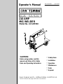 1
1
-
 2
2
-
 3
3
-
 4
4
-
 5
5
-
 6
6
-
 7
7
-
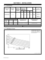 8
8
-
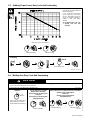 9
9
-
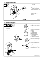 10
10
-
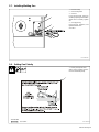 11
11
-
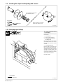 12
12
-
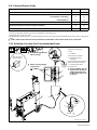 13
13
-
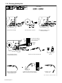 14
14
-
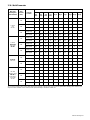 15
15
-
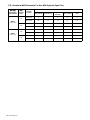 16
16
-
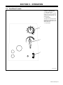 17
17
-
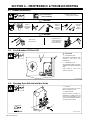 18
18
-
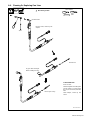 19
19
-
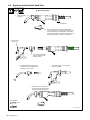 20
20
-
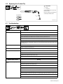 21
21
-
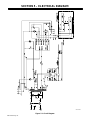 22
22
-
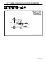 23
23
-
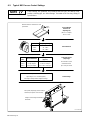 24
24
-
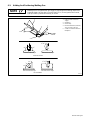 25
25
-
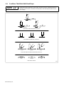 26
26
-
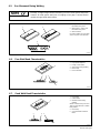 27
27
-
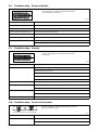 28
28
-
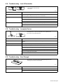 29
29
-
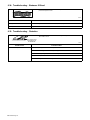 30
30
-
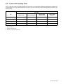 31
31
-
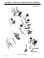 32
32
-
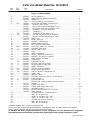 33
33
-
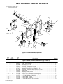 34
34
-
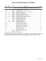 35
35
-
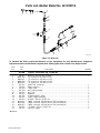 36
36
-
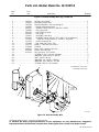 37
37
-
 38
38
-
 39
39
-
 40
40
-
 41
41
-
 42
42
-
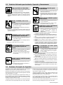 43
43
-
 44
44
-
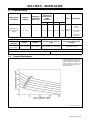 45
45
-
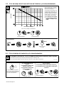 46
46
-
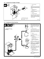 47
47
-
 48
48
-
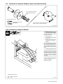 49
49
-
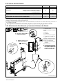 50
50
-
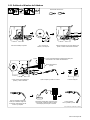 51
51
-
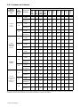 52
52
-
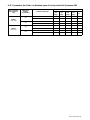 53
53
-
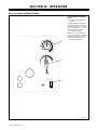 54
54
-
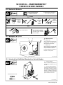 55
55
-
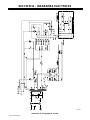 56
56
-
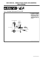 57
57
-
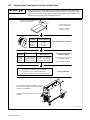 58
58
-
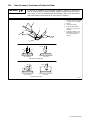 59
59
-
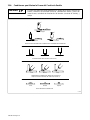 60
60
-
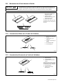 61
61
-
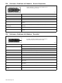 62
62
-
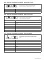 63
63
-
 64
64
-
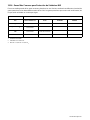 65
65
-
 66
66
-
 67
67
-
 68
68


Craftsman 117.205710 El manual del propietario
- Categoría
- Sistema de soldadura
- Tipo
- El manual del propietario
En otros idiomas
- English: Craftsman 117.205710 Owner's manual
Otros documentos
-
Miller LJ471009U El manual del propietario
-
-
-
-
Harbor Freight Tools 68888 Guía de inicio rápido
-
HobartWelders HANDLER 125 EZ AND H-9B GUN El manual del propietario
-
Forney 271 Manual de usuario
-
-
DeWalt DCW100K Manual de usuario
-
Siemens SJD6-B Manual de usuario