GE UVW9301BLTS Guía de instalación
- Categoría
- Campanas de cocina
- Tipo
- Guía de instalación

Write the model and serial
numbers here:
Model # _________________
Serial # _________________
You can find them on a label
on the inside of the hood.
ESPAÑOL
Para consultar una version en
español de este manual de
instrucciones, visite nuestro sitio de
internet GEAppliances.com.
WALL HOODS
49-80795-1 03-18 GEA
GE is a trademark of the General Electric Company. Manufactured under trademark license.
UVW9301
UVW9361
OWNER’S MANUAL &
INSTALLATION
INSTRUCTIONS
SAFETY INFORMATION .............3
USING THE HOOD
Controls ..................................5
Chef Connect ............................ 6
Wi-Fi Connect ............................ 6
CARE AND CLEANING
Filters ....................................7
Surfaces ..................................8
Lights ....................................8
INSTALLATION INSTRUCTIONS ... 9
TROUBLESHOOTING TIPS ..........21
WARRANTY ......................... 22
ACCESSORIES ...................... 23
CONSUMER SUPPORT ............. 24

2 49-80795-1
THANK YOU FOR MAKING GE APPLIANCES A PART OF YOUR HOME.
Whether you grew up with GE Appliances, or this is your first, we’re happy to have you in the family.
We take pride in the craftsmanship, innovation and design that goes into every GE Appliances
product, and we think you will too. Among other things, registration of your appliance ensures that we
can deliver important product information and warranty details when you need them.
Register your GE appliance now online. Helpful websites and phone numbers are available in the
Consumer Support section of this Owner’s Manual. You may also mail in the pre-printed registration
card included in the packing material.

49-80795-1 3
SAFETY INFORMATION
IMPORTANT SAFETY INFORMATION
READ ALL INSTRUCTIONS BEFORE USING
READ AND SAVE THESE INSTRUCTIONS
WARNING
TO REDUCE THE RISK OF FIRE,
ELECTRIC SHOCK OR INJURY TO PERSONS,
OBSERVE THE FOLLOWING:
A. Use this unit only in the manner intended by the
manufacturer. If you have questions, contact the
manufacturer.
B. Before servicing or cleaning unit, switch power off
at service panel and lock the service disconnecting
means to prevent power from being switched
on accidentally. When the service disconnecting
means cannot be locked, securely fasten a
prominent warning device, such as a tag, to the
service panel.
C. Do not use this unit with any solid-state speed
control device.
D. This unit must be grounded.
CAUTION
FOR GENERAL VENTILATING USE
ONLY. DO NOT USE TO EXHAUST HAZARDOUS
OR EXPLOSIVE MATERIALS AND VAPORS.
CAUTION
TO REDUCE RISK OF FIRE AND
TO PROPERLY EXHAUST AIR, BE SURE TO DUCT
AIR OUTSIDE. DO NOT VENT EXHAUST AIR INTO
SPACES WITHIN WALLS OR CEILINGS OR INTO
ATTICS, CRAWL SPACES OR GARAGES.
WARNING
TO REDUCE THE RISK OF INJURY
TO PERSONS IN THE EVENT OF A RANGE TOP
GREASE FIRE, OBSERVE THE FOLLOWING*:
A. SMOTHER FLAMES with a close-fitting lid, cookie
sheet or metal tray, then turn off the burner. BE
CAREFUL TO PREVENT BURNS. If the flames do
not go out immediately, EVACUATE AND CALL
THE FIRE DEPARTMENT.
B. NEVER PICK UP A FLAMING PAN—You may be
burned.
C. DO NOT USE WATER, including wet dishcloths or
towels—a violent steam explosion will result.
D. Use an extinguisher ONLY if:
1. You know you have a Class ABC extinguisher,
and you already know how to operate it.
2. The fire is small and contained in the area where
it started.
3. The fire department is being called.
4. You can fight the fire with your back to an exit.
* Based on “Kitchen Fire Safety” published by NFPA.

4 49-80795-1
How to Remove Protective Shipping Film and Packaging Tape
Carefully grasp a corner of the protective shipping film
with your fingers and slowly peel it from the appliance
surface. Do not use any sharp items to remove the film.
Remove all of the film before using the appliance for the
first time.
To assure no damage is done to the finish of the
product, the safest way to remove the adhesive from
packaging tape on new appliances is an application of
a household liquid dishwashing detergent. Apply with a
soft cloth and allow to soak.
NOTE: The adhesive must be removed from all parts.
NOTE: For further cleaning instructions/suggestions,
please refer to the Care And Cleaning section.
SAFETY INFORMATION
IMPORTANT SAFETY INFORMATION
READ ALL INSTRUCTIONS BEFORE USING
READ AND SAVE THESE INSTRUCTIONS
WARNING
TO REDUCE THE RISK OF A
RANGE TOP GREASE FIRE:
A. Never leave surface units unattended at high
settings. Boilovers cause smoking and greasy
spillovers that may ignite. Heat oils slowly on
medium settings.
B. Always turn hood ON when cooking at high heat or
when flambéing food (i.e. Crepes Suzette, Cherries
Jubilee, Peppercorn Beef Flambé).
C. Clean ventilating fans frequently. Grease should not
be allowed to accumulate on fan or filter.
D. Use proper pan size. Always use cookware
appropriate for the size of the surface element.
WARNING
TO REDUCE THE RISK OF FIRE,
ELECTRIC SHOCK OR INJURY TO PERSONS,
OBSERVE THE FOLLOWING:
A. Installation work and electrical wiring must be
done by qualified person(s) in accordance with all
applicable codes and standards, including fire-rated
construction.
B. Sufficient air is needed for proper combustion and
exhausting of gases through the flue (chimney) of
fuel burning equipment to prevent back drafting.
Follow the heating equipment manufacturer’s
guidelines and safety standards such as those
published by the National Fire Protection
Association (NFPA), the American Society for
Heating, Refrigeration and Air Conditioning
Engineers (ASHRAE) and the local code authorities.
C. When cutting or drilling into wall or ceiling, do not
damage electrical wiring and other hidden utilities.
D. Ducted fans must always be vented to the outdoors.
E. When applicable, install any makeup (replacement)
air system in accordance with local building
code requirements. Visit GEAppliances.com for
available makeup air solutions.
F. Turn off breaker to adjacent rooms while working.
WARNING
TO REDUCE THE RISK OF FIRE,
USE ONLY METAL DUCTWORK.
Ŷ'RQRWDWWHPSWWRUHSDLURUUHSODFHDQ\SDUWRI\RXU
hood unless it is specifically recommended in this
manual. All other servicing should be referred to a
qualified technician.

49-80795-1 5
Controls
USING THE HOOD: Controls
1. Rangehood Control Panel: The control
panel is located on the front of the canopy. The
position and function of each control pad are
noted below.
2. On/Off: On/Off switch for the fan and lighting up
the display. The fan can be operated by tapping
any of the fan setting pads. Hold On/Off pad for
3 seconds to activate Delay Off feature, which
automatically turns the fan off after 15 minutes.
3. Fan Setting: Speed control for fan. Tap Low
for LOW speed. Med for MEDIUM speed and High
for HIGH speed. Press and hold the High pad for 3
seconds to activate the BOOST speed that will run
for 10 minutes. On Remote, press Up to increase
fan speed, press Down to decrease fan speed,
including Boost.
4. Plus and Minus: The plus (+) and minus (–)
pads control the time for the clock and the timer.
To add time, tap the + pad. To subtract time, tap
the – pad.
5. Timer: Sets a timer for cooking or sets the clock.
To start the timer, tap the Timer pad and the clock
will show “HR” and “MIN”. Tap + or – to add or
subtract time. Tap on the Timer again to start the
countdown. To cancel the timer, tap the Timer pad
again. Hold the Timer pad down for 3 seconds to
set the clock. Tap the + or – to set the the hour.
Tap on the Timer again to set minutes. Tap on the
Timer again to lock in the time. Clock will sync once
the unit is connected to Wi-Fi.
6. Light: Controls the lights. Tap the Light pad to
turn the lights on fully. Tap the Light pad again and
the lights will dim. Tap the Light pad a third time to
turn off the lights.
7. Chef Connect: Hold the Chef Connect pad
down for 3 seconds to activate the Bluetooth
®
. This
is a Bluetooth
®
pairing feature for use with other
compatible Chef Connect enabled products on a
cooktop or range. When the device is paired, the light
and fan will turn ON at the Default Sync Settings upon
receiving a command from the range or cooktop. It
will remain ON at that setting until the user changes
it. See the Chef Connect section for more details.
8. Reset Filter: The red LED indicator above the
Reset Filter pad turns on as a reminder to change
/clean the filter. Hold the Reset Filter pad for 3
seconds to turn off. Tap the Reset Filter pad again
to begin recalculating the time. While this indicator
reminds user to change/clean filters, the filters
should be cleaned regularly. Please refer to the
Filters section.
9. Wi-Fi: Hold down the Light and Chef Connect
pads for three seconds to activate the Wi-Fi connect
mode. The Wi-Fi symbol above the clock blinks for
3 seconds and then becomes solid. See the Wi-Fi
section for more details. On Remote, press Wi-Fi to
toggle Wi-Fi function.
10. Delay Off (Remote only): Press and hold
Delay Off to toggle Delay Off function.
3
4
25678
1 9
3
6
9
10
7
2
Remote Control

6 49-80795-1
Wi-Fi Connect
USING THE HOOD: Chef Connect / Wi-Fi Connect
* Compatible Apple or Android devices and home Wi-Fi network required.
Connecting your Wi-Fi Connect Enabled hood (on some models)
Your GE Appliances hood is designed to provide you with two-way communication between your appliance and smart
device. By using the GE Appliances Wi-Fi Connect features, you will be able to control essential hood operations such
as fan speed, light functions, timer/clock function, delay off and filter reset using your smartphone or tablet.*
What you will need
Your GE Appliances hood uses your existing home Wi-Fi
network to communicate between the appliance and your
smart device. In order to setup your GE Appliances hood,
you will need to gather some information:
1. Each GE Appliances hood has a connected
appliance information label that includes an
Appliance Network Name and Password. These
are the two important details that you will need to
connect to the appliance. The label is located on the
side of the unit behind the filters.
2. Have your smart phone or tablet ready with the ability
to access the internet and download apps.
3. You will need to know the password of your home
Wi-Fi router. Have this password ready while you are
setting up your GE Appliances hood.
Connect your GE Appliances hood
1. On your smart phone or tablet visit
www.GEAppliances.com/connect to learn more about
connected appliance features and to download the
appropriate app.
2. Follow the app onscreen instructions to connect your
GE Appliances hood.
3. Once the process is complete, the connection light
located on your GE Appliances hood display will stay
on solid and the app will confirm you are connected.
4. If the connection light does not turn on or is blinking,
follow the instructions on the app to reconnect. If
issues continue please call 800.220.6899 and ask for
assistance regarding hood wireless connectivity.
To connect additional smart devices, repeat steps 1 and 2.
Note that any changes or modifications to the remote
enable device installed on this hood that are not
expressly approved by the manufacturer could void the
user’s authority to operate the equipment.
Chef Connect Operation Bluetooth
®
Connection
To pair with another device:
To start the pairing process on the hood, press and hold
the Chef Connect button for 3 seconds. The backlight
for all the icons will light up until the hood is paired with
the range or other device. If the pairing is successful,
the Bluetooth
®
symbol above the clock will turn on and
become solid.
It will time out after 2 minutes if the pairing is not
completed, after which the pairing sequence will need to
be restarted.
To cancel pairing:
To cancel the pairing, hold the Chef Connect button
down for 3 seconds and then turn off the hood.
Default Sync Settings:
The factory default setting for the light will be the brightest.
The factory default setting for the fan sync will be OFF.
The user can change the Default Sync Settings by
pressing and holding the Low button for 3 seconds. This
will enter the Default Settings Mode. Once in this mode,
the backlights for all buttons will blink on/off indefinitely
and the fan and light will switch to the current Default
Sync Setting, so the user knows what the current default
value is. At this time, set the light and fan to the desired
default levels. Once the user is satisfied with the selection,
press and hold the Off button for 3 seconds. This will exit
this mode. At that time the backlights will stop blinking and
the state of the fan and light will change back to their prior
state before entering the Default Settings Mode.
Chef Connect
Sample Label
Connected Appliance Information
FCC ID: ZKJ-WCATA005
IC: 10229A-WCATA001
MAC ID: ************
Network: ************
Password: **********

49-80795-1 7
Be sure the circuit breaker is off and all surfaces are cool before cleaning or servicing any part of the vent hood.
Metal Grease Filter
The metal filters trap grease during cooking.
The filters must ALWAYS be in place when the hood
is in use. The grease filters are dishwasher-safe and
should be cleaned every month, depending on the
usage of the hood.
To remove:
Open the filter cover panel and disengage the filter lock
to release the filter.
To replace:
Fit the tabs at the bottom of the filter into the slots in the
back of the filter opening. Lift up the front side of the filter
and push gently until the filter locks into place. Make sure
the filter lock is in the closed position to secure the filter.
NOTE: The front panel covers the filters and must be
pressed up and then pulled down to access the filters.
To clean:
Swish the filter in hot soapy water and rinse in clean
water or wash it in the dishwasher. Do not use abrasive
cleansers.
NOTE: Some discoloration of the filter may occur in the
dishwasher.
Charcoal Filter (for recirculation installation only)
If the model is not vented to the outside, the air needs to
be recirculated through a disposable charcoal filter that
helps remove smoke and odors.
NOTE: DO NOT rinse, or put charcoal filter in an
automatic dishwasher.
The charcoal filter is included with the unit. It cannot
be cleaned, It must be replaced when Reset Filter
LED indicator comes on. It is recommended that the
charcoal filter be replaced every 6 months or if it is
noticeably dirty or discolored.
Order Charcoal Filter UXCF91
To inquire about purchasing replacement charcoal filters
or to find the location of a dealer nearest you, please call
our toll-free number:
National Parts Center 800.626.2002
To install:
1. Remove the metal filters—see Metal Grease Filter
section.
2. Install the charcoal filter mounts to either side of the
motor using three screws per side.
3. Insert the tab on the charcoal filter into the triangular
slot on the mount.
4. Clip the charcoal filter in until it is locked.
5. Repeat with second filter on the other side of the motor.
6. Replace the metal filters - See Metal Grease Filter section.
To remove:
1. Remove the metal filters—see Metal grease filter
section.
2. Unclip the charcoal filter by pressing the release clip.
3. Carefully remove charcoal filter from tab.
Filters
CARE AND CLEANING: Filters
Charcoal
Filter Mount

8 49-80795-1
Lights
Painted Surfaces and Black Stainless Color (on some models)
Do not use a steel wool pads or other abrasive
cleaners; they will scratch the surface.
Clean grease-laden surfaces of the hood frequently. To
clean the hood surface, use a hot, damp cloth with a
mild detergent suitable for painted surfaces. About one
tablespoon of ammonia may be added to the water. Use
a clean, hot, damp cloth to remove soap. Dry with a dry,
clean cloth.
NOTE: When cleaning, take care not to come in contact
with filters and other surfaces.
CAUTION
When cleaning the hood surfaces,
be certain that you do not touch the light with moist
hands or cloth. A warm or hot light may break if
touched with a moist surface. Always let the light
cool completely before cleaning around it.
CAUTION
Allow lights to cool before touching.
1. Before attempting to replace the lights, make sure that
the light switch is turned off.
2. Rotate light counterclockwise to unlock and pull out.
Wearing latex gloves may offer a better grip.
3. Replace with new light of same type, making sure
pins are inserted properly into the sockets of the lamp
holder and turn clockwise to lock.
All lamps need to be GU10 compatible.
Surfaces
CARE AND CLEANING: Surfaces / Lights
Rotate the lamp until the
pins are located in narrow
neck of the socket to lock.
Lamp
Holder
Stainless Steel Surfaces (on some models)
Do not use a steel wool pad; it will scratch the
surface.
To clean the stainless steel surface, use warm sudsy
water or a stainless steel cleaner or polish. Always wipe
the surface in the direction of the brush line. Follow
the cleaner instructions for cleaning the stainless steel
surface. Cleaners with oxalic acid such as Bar Keepers
Friend Soft Cleanser™ will
remove surface rust, tarnish, and
small blemishes. To receive a
coupon for a trial sample of Bar
Keepers Friend Soft Cleanser™
follow the link below or scan the
QR Code.
www.barkeepersfriend.com/ge
Use only a liquid cleanser free of grit and rub in the
direction of the brush lines with a damp soft sponge.
To inquire about purchasing stainless steel appliance
cleaner or polish, or to find the location of a dealer
nearest you, please call our toll-free number:
National Parts Center
800.626.2002
GEApplianceParts.com

49-80795-1 9
Installation
Instructions
“If you have questions, call GE Appliances at 800.GE.CARES (800.432.2737)
or visit our website at: GEAppliances.com”
INSTALLATION INSTRUCTIONS
BEFORE YOU BEGIN
Read these instructions completely and carefully.
Ŷ
IMPORTANT — Save these
instructions for local inspector’s use.
Ŷ
IMPORTANT — Observe all governing
codes and ordinances.
Ŷ
Note to Installer – Be sure to leave these
instructions with the Consumer.
Ŷ
Note to Consumer – Keep these instructions for
future reference.
Ŷ
Skill level – Installation of this vent hood requires
basic mechanical and electrical skills.
Ŷ
Completion time – Approximately 1 to 3 hours
Ŷ
Proper installation is the responsibility of the
installer.
Ŷ
Product failure due to improper installation is not
covered under the Warranty.
FOR YOUR SAFETY
WARNING
Before beginning the installation,
switch power off at service panel and lock the
service disconnecting means to prevent power from
being switched on accidentally. When the service
disconnecting means cannot be locked, securely
fasten a prominent warning device, such as a tag,
to the service panel.
CAUTION
Due to the weight and size of
these vent hoods and to reduce the risk of personal
injury or damage to the product, TWO PEOPLE
ARE REQUIRED FOR PROPER INSTALLATION.
WARNING
Disconnect all electrical power
at the main circuit breaker or fuse box before
installing.
WARNING
TO REDUCE THE RISK OF FIRE,
ELECTRIC SHOCK OR INJURY TO PERSONS,
OBSERVE THE FOLLOWING:
A. Installation work and electrical wiring must be
done by qualified person(s) in accordance with
all applicable codes and standards, including
fire-rated construction.
B. Sufficient air is needed for proper combustion
and exhausting of gases through the flue
(chimney) of fuel burning equipment to prevent
back drafting. Follow the heating equipment
manufacturer’s guidelines and safety standards
such as those published by the National Fire
Protection Association (NFPA), the American
Society for Heating, Refrigeration and Air
Conditioning Engineers (ASHRAE) and the local
code authorities.
C. When cutting or drilling into wall or ceiling, do
not damage electrical wiring and other hidden
utilities.
D. Ducted fans must always be vented to the
outdoors.
E. Turn off breaker to adjacent rooms while
working.
WARNING
TO REDUCE THE RISK OF FIRE,
USE ONLY METAL DUCT WORK.
Wall Hoods
UVW9301, UVW9361

10 49-80795-1
Installation Preparation
INSTALLATION CLEARANCES
These vent hoods are designed to be installed onto
a wall with no above cabinets.
The vent hood must be installed between the 24”
required minimum and 36” recommended maximum
above the cooking surface. For supplied duct cover
ceiling heights, see Installation Height Table.
NOTE: Installation height should be measured from
the cooking surface to the lowest part of the hood.
The hood must be installed onto a wall. It can be
vented to the outdoors, or it can be installed for
recirculating operation. For recirculation operation,
see Recirculation Install Planning.
PRODUCT DIMENSIONS
INSTALLATION PREPARATION
26-5/8Ǝ min. - 50-7/8Ǝ max.
12-1/4Ǝ
2-3/4Ǝ
4-5/8Ǝ
13-13/16Ǝ
25-3/4Ǝ
30ƎRUƎ
20Ǝ
24” Required Min.
36” Recommended Max.
20Ǝ
30ƎRUƎ
Filter Cover Panel
12-1/8Ǝ
8Ǝ
6-15/16Ǝ
10-5/8Ǝ

49-80795-1 11
INSTALLATION PREPARATION
Installation Preparation
PLAN THE INSTALLATION
CAUTION
To reduce risk of fire and to
properly exhaust air, be sure to duct the air outside.
Do not vent exhaust air into spaces within walls or
ceilings or into attics, crawl spaces, or garages.
PARTS SUPPLIED FOR INSTALLATION
Ŷ 1 Hardware Package
Ŷ 1 Literature Package
Ŷ Recirculation Duct (for recirculation install only)
Ŷ Charcoal filters (recirculation mode)
PARTS NEEDED FOR INSTALLATION
Ŷ 1 Strain Relief
Ŷ 1 Wall or Roof Cap (for ducted venting only)
Ŷ All Metal Ductwork (for ducted venting only)
WARNING
PERSONAL INJURY HAZARD
Because of the weight and size of the rangehood
canopy. It is recommended that 2 people are used
to install the range hood. Failure to properly lift
rangehood could result in damage to the product or
personal injury.
NOTE: This rangehood can be installed as either
ducted or recirculation. In a ducted application,
this rangehood can be vented through the wall
or ceiling. When installed for recirculation, the
rangehood vents out the sides of the duct cover.
NOTE: Before making any cuts or holes for
installation, determine which venting method will be
used and carefully calculate all measurements.
TOOLS AND MATERIALS REQUIRED
(NOT SUPPLIED)
REMOVE THE PACKAGING
CAUTION
Wear gloves to protect against
sharp edges.
Ŷ Remove the duct covers.
Ŷ Remove the hardware bag, literature package
and other boxed parts.
Ŷ Remove and properly discard the protective
plastic wrapping and other packaging materials.
Wire cutter/stripper
Level
Aluminized
duct tape
Safety glasses
Phillips screwdriver
Strain relief for
junction box
Electric drill with #2 Phillips
and 1/8" drill bits
UL listed wire nuts
8" round duct
(length will vary)
Pencil and tape measure
Gloves

12 49-80795-1
Installation Preparation
INSTALLATION DIMENSIONS
The Wall Hoods duct covers can be adjusted for
different ceiling heights depending on the distance
between the bottom of the hood and the cooktop
(distance X). See Installation Height Table.
RANGE HOOD COMPONENTS
RECIRCULATION COMPONENTS
INSTALLATION PREPARATION
A. Wall Hood
B. Upper Duct Cover
C. Lower Duct Cover
D. Mounting Screws
E. Duct Cover
Mounting Bracket
F. Damper
G. Hood Mounting
Bracket
H. Mounting Anchors
J. Machine Screws
K. Recirculation Box
L. Wood Screws
7/8Ǝ min
25-1/8Ǝ max
25-3/4Ǝ
2-3/4Ǝ
36”
X
X = Distance From Hood To
Cooktop
(Varies depending on installation)
Required Min - 24”,
Recommended Max - 36”
Also consult cooktop
manufacturer’s recommendation
For higher ceiling
installations up to
12', use the 12' High
Ceiling Duct Cover
kit (UX12DC93) for
your model.
For higher ceiling
installations up to
14', use the 14' High
Ceiling Duct Cover
kit (UX14DC93) for
your model.
Typical Range
Upper Duct
Cover
Lower
Duct Cover
Hood Body
Required Min & Recommended
Max Ceiling Height Examples
X = 24" X = 36"
Min Min
7' 6" 9' 6"
Max Max
8' 6" 10' 5"
Required Min Ceiling
Height for Recirculation
X = 24" X = 36"
Min Min
7' 10" 8' 10"
K
A
D
F
J
E
D
J
K
J
H
H
G
L
C
B
J
J
J
H
D
L
HARDWARE COMPONENTS
NOTE: The chimney extension replaces the upper
and lower chimney shipped with the range hood.
The hardware included with the hood should be
saved and also used with the chimney extension.
E
L
H
J
Phillips Head
Wood Screw
3/16" x 1-15/16"
(QTY: 4)
Phillips Head
Machine Screw
1/8" x 3/8"
(QTY: 14)
Phillips Head
Mounting Anchors
Screws
3/16" x 1-1/2"
(QTY: 6)
Mounting Anchors
(QTY: 6)
D

49-80795-1 13
INSTALLATION PREPARATION
Installation Preparation
INSTALLATION HEIGHT TABLE
(UX12DC93SS or
UX12DC93TS)
(UX14DC93SS or
UX14DC93TS)
Installation Height with Supplied Duct Covers
Optional High Ceiling Duct Cover
up to 12 ft.
(not included with unit)
Optional High Ceiling Duct Cover
up to 14 ft.
(not included with unit)
Ceiling
Height (ft./in.)
Possible Vented
Install Height
(in.)
Possible Vented
Install Height
(Recirculation
vented Holes
Hidden) (in.)
Possible
Recirculation
Install
Height (in.)
Ceiling
Height (ft./in.)
Vented and
Recirculation
Height (in.)
Ceiling
Height (in.)
Vented and
Recirculation
Install
Height (in.)
7' 6" 24 24 9' 3" 24 12' 24-36
7' 7" 24-25 24-25 9' 4" 24-25 12' 1" 24-36
7' 8" 24-26 24-26 9' 5" 24-26 12' 2" 24-36
7' 9" 24-27 24-27 9' 6" 24-27 12' 3" 24-36
7' 10" 24-28 24-28 24 9' 7" 24-28 12' 4" 24-36
7' 11" 24-29 24-29 24-25 9' 8" 24-29 12' 5" 24-36
8' 24-30 24-30 24-26 9' 9" 24-30 12' 6" 24-36
8' 1" 24-31 24-31 24-27 9' 10" 24-31 12' 7" 24-36
8' 2" 24-32 24-32 24-28 9' 11" 24-32 12' 8" 24-36
8' 3" 24-33 24-33 24-29 10' 24-33 12' 9" 24-36
8' 4" 24-34 24-34 24-30 10' 1" 24-34 12' 10" 24-36
8' 5" 24-35 24-35 24-31 10' 2" 24-35 12' 11" 24-36
8' 6" 24-36 24-36 24-32 10' 3" 24-36 13' 24-36
8' 7" 24-36 24-36 24-33 10' 4" 24-36 13' 1" 25-36
8' 8" 24-36 24-36 24-34 10'5"-11'3" 24-36 13' 2" 26-36
8' 9" 24-36 24-36 24-35 11' 4" 24-36 13' 3" 27-36
8' 10" 24-36 24-36 24-36 11'5" 24-36 13' 4" 28-36
8' 11" 24-36 24-36 24-36 11'6" 24-36 13' 5" 29-36
9' 24-36 24-36 24-36 11'7" 24-36 13' 6" 30-36
9' 1" 24-36 24-36 24-36 11'8" 25-36 13' 7" 31-36
9' 2" 24-36 25-36 24-36 11'9" 26-36 13' 8" 32-36
9' 3" 24-36 26-36 24-36 11'10" 27-36 13' 9" 33-36
9' 4" 24-36 27-36 24-36 11' 11" 28-36 13' 10" 34-36
9' 5" 24-36 28-36 24-36 12' 29-36 13' 11" 35-36
9' 6" 25-36 29-36 25-36 14' 36
9' 7" 26-36 30-36 26-36
9' 8" 27-36 31-36 27-36
9' 9" 28-36 32-36 28-36
9' 10" 29-36 33-36 29-36
9' 11" 30-36 34-36 30-36
10' 31-36 35-36 31-36
10' 1" 32-36 36 32-36
10' 2" 33-36 33-36
10' 3" 34-36 34-36
10' 4" 35-36 35-36
10' 5" 36 36
*Based on a 36" electric range height.
For gas range, start chart at 92" and subtract 2" for the maximum install height for each block.
7/8Ǝ min
29-7/16Ǝ max
7/8Ǝ min
46-1/4Ǝ max
46-7/8" 46-7/8"
12" High Ceiling Duct Cover Kit 14" High Ceiling Duct Cover Kit
Upper
Duct Cover
Upper
Duct Cover
Lower
Duct Cover
Lower
Duct Cover
Hood Body Hood Body

14 49-80795-1
INSTALLATION PREPARATION
ADVANCE PLANNING
Duct Install Planning
Ŷ This hood is designed to be vented vertically
through the ceiling. Use an 8" round duct. Use
locally supplied elbows to vent horizontally
through the rear wall.
Ŷ Use metal ductwork only.
Ŷ Determine the exact location of the vent hood.
Ŷ Plan the route for venting exhaust to the
outdoors. To maximize the ventilation
performance of the vent system:
1. Minimize the duct run length and number of
transitions and elbows.
2. Maintain a constant duct size.
3. Seal all joints with duct tape to prevent any leaks.
NOTE: Flexible vent is not recommended. Flexible
vent creates back pressure and air turbulence that
greatly reduces performance.
Ŷ Maximum equivalent duct length for 100 CFM:
150 foot for vent hoods.
Ŷ Install a wall cap or roof cap with damper at the
exterior opening. Purchase the wall or roof cap
and any transition and length of duct needed in
advance.
Ŷ When applicable, install any makeup (replacement)
air system in accordance with local building code
requirements. Use makeup air kit JXMUA8.
Vent system can terminate either through the roof
RUWKHZDOO7RYHQWWKURXJKDZDOODHOERZLV
needed and installed immediately above the hood.
Recirculation Install Planning
A recirculation duct (included) and charcoal
filter (included) are necessary for recirculation
installation.
Power Supply Planning
The location of the power supply connection is called
out in the Installing The Hood Bracket Mount section.
POWER SUPPLY
IMPORTANT – (Please read carefully)
WARNING
FOR PERSONAL SAFETY, THIS APPLIANCE
MUST BE PROPERLY GROUNDED.
Remove house fuse or open circuit breaker before
beginning installation.
Do not use an extension cord or adapter plug with
this appliance. Follow National Electrical Codes or
prevailing local codes and ordinances.
Electrical supply
These vent hoods must be supplied with 120V,
60Hz, and connected to an individual, properly
grounded branch circuit, and protected by a 15 or
20 amp circuit breaker or time delay fuse.
Ŷ Wiring must be 2 wire with ground.
Ŷ If the electrical supply does not meet the above
requirements, call a licensed electrician before
proceeding.
Ŷ Route house wiring as close to the installation
location as possible in the ceiling or wall.
Ŷ Connect the wiring to the house wiring in
accordance with local codes.
Grounding instructions
The grounding conductor must be connected to
a ground metal, permanent wiring system, or an
equipment-grounding terminal or lead on the hood.
WARNING
The improper connection of the
equipment-grounding conductor can result in a risk
of electric shock. Check with a qualified electrician
or service representative if you are in doubt whether
the appliance is properly grounded.
Installation Preparation
Roof Cap
Round Duct
Wall Cap
Add Insulation
and/or Caulk
Add Insulation
and/or Caulk
Add tape to joint
Hood

49-80795-1 15
NEW CONSTRUCTION, PRE-PLANNING, OR REMODELING
NOTE: For existing construction, skip to the section, Installing The Hood Bracket Mount.
Ŷ Install horizontal wood supports between 2 wall
studs that align with the vertical mounting height
locations shown in the illustration.
Ŷ The horizontal supports must be flush with the room
side studs.
Ŷ For ducted installation, the hole for the duct in the
ceiling must be centered 5" away from the finished
rear wall.
Ŷ The bottom support aligns with the hood mounting
bracket. This height depends on the desired height
of the hood.
Ŷ The top support must be flush with the ceiling.
Ŷ The electrical wiring can be located 5-1/2” to the left
or right (junction box is on the left) of the centerline.
Must remain 7/16” above the back panel and 5” from
the ceiling, refer to illustration on next page.
INSTALLATION
Installation
Acceptable
area for
electrical
wiring
Acceptable
area for
electrical
wiring
14-3/8"
14-3/8"
5"
5"
11"
11"
See the Installation
Height Table for possible
installation heights.
24-36" + 1-1/8"
Wood Supports
• 36" minimum
width centered
• 4" height
From the lower left corner of
the gray shaded area, it is
recommended to have at least
20" of house electrical wiring.
* 36” or 38” Range
* Typical electrical range is 36"
and typical gas range is 38"

16 49-80795-1
Installation
INSTALLATION
INSTALLING THE HOOD BRACKET MOUNT
Hood Body
1. Put a protective covering over the surface
below the location of the hood to protect from
dirt and/or damage.
2. Determine and mark the centerline (C) on the
wall (draw line up to the ceiling) where the range
hood will be installed. Based on the ceiling height,
determine the distance between 24” required
min, 36” recommended max (X) needed between
the cooking surface (B) and the bottom of the
hood. Draw a horizontal line at X. Align the install
template so that the bottom of the template is
centered and is level with the horizontal line drawn
at height X.
3. Find the stud locations and mark them on the
template.
4. Place the hood mounting bracket (G) on its outline
on the template. Mark at least one wood screw (L)
location that is on a stud. If another stud cannot be
found, mark at least two other screw locations for
mounting anchors, one on each side of the wood
screw (L). Remove the bracket from the wall and
install the mounting anchors (H). Place the hood
mounting bracket (G) back on the wall and mount it
with the wood screws (L) and mounting screws (D)
as needed. It is recommended to create a pilot hole
in the studs for wood screws (L).
Duct Covers and Power Supply
1. Place the duct cover bracket (E) on the wall so that
its edge is against the ceiling and level, making
sure the slots are in direct contact with the wall.
Align the center notches of the bracket and the
centerline. Mark the location of the screw holes
furthest apart from the center line if possible. If one
of the screw holes aligns with a stud, then a wood
screw will be used for that location. For the other
hole or if there are no studs, install 2 mounting
anchors (H). Place the duct cover bracket (E)
on the wall and install with wood screws (L) and
mounting screws (D) as needed.
2. The house electrical wiring must fall in the gray
shaded area shown below. From the lower left
corner of the shaded area, a minimum of 20” of
house electrical wiring is recommended to reach
the electrical junction box on the hood.
C
B
1-1/8"
X
24 to 36"
Hood Mounting Bracket
Mounting
Screw
Mounting
Screw
Wood Screw
Mounting
Anchors
Ǝ%HORZ&HLOLQJ
C
Ceiling
Ǝ
16-7/8"
Acceptable
area for house
electrical
wiring

49-80795-1 17
INSTALLATION
INSTALLING THE HOOD
Remove the grease filters from
the unit and set aside. The
grease filters are removed by
pressing the handle in the front
of the filter. When replacing,
make sure that the filters are
properly positioned with the
handles in front and visible.
NOTE: On some models, the front panel covers the
filters and must be pulled down to access the filters.
NOTE: This bracket must be removed prior to
installation. Remove 2 front and 2 bottom screws per
illustration bellow.
1. Securely press the damper on top of the exhaust
opening. Check that the damper opens freely.
Attach damper to hood using machine screws
(J) provided.
2. Remove and properly discard the protective plastic
wrapping from the hood and grease filter. Remove
the template off the wall.
3. Mount the Range Hood:
Ŷ Using 2 or more people, lift the range hood and
place on the hood mounting bracket. Make sure
the bracket fully engages the hood body.
Ŷ Install the 2 mounting screws (D) or wood screws
(L) as needed into the designated holes on the
back panel.
Installation

18 49-80795-1
Installation
INSTALLATION
ELECTRICAL CONNECTION
1. Remove the electrical junction box cover.
2. Remove the electrical box knockout.
3. Feed the Power Supply Cable through the hole
and secure with a strain relief.
4. Attach the white lead of the power supply (A) to
the white lead of the range hood (D) with a wire
nut. Attach the black lead of the power supply (B)
to the black lead of the range hood (C) with a wire
nut. Connect the house ground wire under the
green grounding screw (E).
5. Reattach the electrical junction box cover.
INSTALLING THE HOOD (Cont.)
A
Vented Installations
Connect the house ducting to the damper on the
hood body. Seal all connections with duct tape
(Do not use screws).
B
Recirculation (Non-vented)
NOTE: A recirculation box, a charcoal filter, and a
bracket are included with the hood and are necessary
for recirculation installation.
1. Attach the recirculation box to the duct over
mounting bracket with 4 machine screws (J).
2.
Connect the ducting from the exhaust outlet on
the hood to the recirculation box. Use duct tape
to seal the connections on the recirculation box
and the exhaust outlet.
House Wiring
A
E
D
C
B
Hood Wiring
Electrical Box
Knockout with
Strain Relief
Ceiling
House
Ducting
Recirculation Box
Duct Cover
Mounting
Bracket
Use tape
(Do not use screws)

49-80795-1 19
INSTALL DUCT COVERS
1. For ducted and recirculation installation:
Remove protective film from duct covers. Place
the upper duct cover so that it slides down inside
of the lower duct cover.
NOTE: For recirculation, the upper duct cover
must be installed with the exhaust vents on the
top towards the ceiling.
Depending on the amount of overlap between
the top and bottom duct covers, the top may be
reversed to hide vent holes. Refer to Installation
Height Table for possible heights.
Place the set of duct covers by sitting them
down to fit securely on top of the hood. Finish
attaching the lower duct cover to the body of the
hood with two machine screws (J) that screw
from up underneath the hood.
2. Install the upper duct cover by carefully raising
it up to avoid scratching until it reaches the
ceiling. Push the duct cover flush against the
wall, then use two machine screws (J) to mount
the upper duct to the duct mounting bracket.
3. If recirculating, install the charcoal filters. Then
reinstall the grease filters to the hood, see the
Filters section.
4. Turn the power supply on. Turn on the blower
and light. If the range hood does not operate,
check that the circuit breaker is not tripped or the
house fuse blown. If the unit still does not operate,
disconnect the power supply and check that the
wiring connections have been made properly.
Installation
INSTALLATION

20 49-80795-1
Installation
INSTALLATION
MAKE UP AIR TECHNOLOGY
Note to Installers and Inspectors: This product comes equipped with a simple installation feature that limits
maximum CFM levels in order to comply with certain local codes or regulations. This installation method may not
be necessary for all installations, please refer to your local codes for further guidelines.
CAUTION
Hood must be disconnected from main power prior performing the conversion instructions
listed below. Failure to do so could result in personal injury or damage to the product.
To modify unit (if needed for local codes):
390CFM or 290CFM
By design, the maximum blower speed is greater than
400 CFM. For local codes requiring reduced CFM,
modify the wiring as described below:
1. Open the filter cover panel and remove the filters.
2. Remove the control board box cover.
3. Locate the motor harness plugged into the control
board.
4. A -
For a maximum of 390 CFM
Unit can operate with 4 speeds
(Low, Medium, High, Boost).
1. Disconnect the connector of the blue wire
from the red wire.
2. Connect the 2 red wires together.
3. Cut off the blue unused connector and crimp
the end if desired.
B -
For a maximum of 290 CFM
Unit can operate with 3 speeds
(Low, Medium, High).
1. Disconnect the connector of the blue wire
from the red wire.
2. Cut off the blue unused connector and crimp
the end if desired.
5. Reattach the control board box cover and install
Filters, see Filters section.
Note to Inspectors: To verify this product was
installed in either configuration, check motor wiring
connections as described above.
Motor Harness Connector
Blue
Red
Red
Motor Harness
Control Board
Box Cover

49-80795-1 21
Save time and money! Review the charts on the following pages first and you may not need to call for service.
Problem Possible Cause What To Do
Fan/Light does not
operate when button is
turned ON
A house fuse may be blown or a circuit
breaker tripped.
Replace fuse or reset circuit breaker.
Loud or abnormal
airflow noise
Wrong duct size used in installation. This hood requires 8” ducting to perform optimally.
Using smaller duct pipe will cause reduced venting.
Minimize the duct run length and number of transitions
and elbows. GE Appliances service technicians cannot
correct this issue if installed improperly.
Fan fails to circulate
air or moves air slower
than normal and/or
fan is making loud or
abnormal airflow noise
Obstructions in duct work. Make sure nothing is blocking the vent. Make sure
your wall or roof cap has a blade or door.
Damper blade on wall or roof cap may
not be open.
Make sure damper swings freely. Damper blades may
flip over and will not fully open when this happens.
Adjust to original position.
Metal grease filter and charcoal filter (if
present) may be dirty.
Clean the metal grease filter and replace charcoal filter
(if present). See Care and Cleaning of the Vent Hood.
Insufficient makeup (replacement) air Sufficient makeup (replacement) air is required for
exhausting appliances to operate to rating. Check with
local building codes, which may require or strongly
advise the use of makeup air. Visit GEAppliances.com
for available makeup air solutions.
Early light failure Light wattage is too high. Replace with correct wattage.
Fan keeps going off
and on
The motor is probably overheating and
turning itself off. This can be harmful to
the motor.
Check to be sure the filters are clean. If off and on
cycling continues, call for service.
Hood will not work
remotely
Router issues, no wireless signal, etc. For assistance with hood wireless network connectivity,
please call 800.220.6899.
Hood is not connected.
Troubleshooting tips ... Before you call for service
TROUBLESHOOTING TIPS

22 49-80795-1
Staple your receipt here. Proof of the original purchase
date is needed to obtain service under the warranty.
GEAppliances.com
All warranty service is provided by our Factory Service Centers, or an authorized Customer Care
®
technician. To schedule
service online, visit us at www.geappliances.com/service_and_support/, or call GE Appliances at 800.GE.CARES
(800.432.2737). Please have your serial number and your model number available when calling for service.
Servicing your appliance may require the use of the onboard data port for diagnostics. This gives a GE Appliances factory
service technician the ability to quickly diagnose any issues with your appliance and helps GE Appliances improve its
products by providing GE Appliances with information on your appliance. If you do not want your appliance data to be
sent to GE Appliances, please advise your technician not to submit the data to GE Appliances at the time of service.
What GE Appliances will not cover:
Ŷ Service trips to your home to teach you how to use
the product.
Ŷ Improper installation, delivery, or maintenance.
Ŷ Failure of the product if it is abused, misused,
modified, or used for other than the intended purpose
or used commercially.
Ŷ Replacement of house fuses or resetting of circuit
breakers.
Ŷ Damage to the product caused by accident, fire,
floods, or acts of God.
Ŷ Damage to finish, such as surface rust, tarnish, or small
blemishes not reported within 48 hours of delivery.
Ŷ Incidental or consequential damage caused by
possible defects with this appliance.
Ŷ Damage caused after delivery.
Ŷ Product not accessible to provide required service.
Ŷ Service to repair or replace light bulbs, except for LED
lamps.
WARRANTY
GE Appliances Vented Range Hood Warranty
EXCLUSION OF IMPLIED WARRANTIES
Your sole and exclusive remedy is product repair as provided in this Limited Warranty. Any implied warranties,
including the implied warranties of merchantability or fitness for a particular purpose, are limited to one year or
the shortest period allowed by law.
This warranty is extended to the original purchaser and any succeeding owner for products purchased for home use
within the USA. If the product is located in an area where service by a GE Appliances Authorized Servicer is not available,
you may be responsible for a trip charge or you may be required to bring the product to an Authorized GE Appliances
Service location for service. In Alaska, the warranty excludes the cost of shipping or service calls to your home.
Some states do not allow the exclusion or limitation of incidental or consequential damages. This warranty gives you
specific legal rights, and you may also have other rights which vary from state to state. To know what your legal rights
are, consult your local or state consumer affairs office or your state’s Attorney General.
Warrantor: GE Appliances, a Haier company
Extended Warranties: Purchase a GE Appliances extended warranty and learn about special discounts that are
available while your warranty is still in effect. You can purchase it online anytime at
www.geappliances.com/service_and_support/shop-for-extended-service-plans.htm
or call 800.626.2224 during normal business hours. GE Appliances Service will still be there after your warranty expires.
For the period of GE Appliances will replace
One year
From the date
of the original
purchase
Any part of the cooking product which fails due to a defect in materials or workmanship.
During this limited one-year warranty, GE Appliances will provide, free of charge, all labor
and related service costs to replace the defective part.

49-80795-1 23
ACCESSORIES
Looking For Something More?
GE Appliances offers a variety of accessories to
improve your cooking and maintenance experiences!
Refer to the Consumer Support page for phone numbers
and website information.
The following products and more are available:
Accessories
Parts
Power Cord Kit
Make-up Air Kit
Charcoal Filter
Recirculation Kit
Remote Control
12' High Ceiling Duct Cover Kit
14' High Ceiling Duct Cover Kit
Cleaning Supplies
CitruShine™ Stainless Steel Wipes
CERAMA BRYTE
®
Stainless Steel Appliance Cleaner
Bar Keepers Friend Soft Cleanser™

24 49-80795-1
Consumer Support
CONSUMER SUPPORT
Printed in China
GE Appliances Website
Have a question or need assistance with your appliance? Try the GE Appliances Website 24 hours a day, any day
of the year! You can also shop for more great GE Appliances products and take advantage of all our on-line support
services designed for your convenience. In the US: GEAppliances.com
Register Your Appliance
Register your new appliance on-line at your convenience! Timely product registration will allow for enhanced
communication and prompt service under the terms of your warranty, should the need arise. You may also mail in
the pre-printed registration card included in the packing material. In the US: GEAppliances.com/register
Schedule Service
Expert GE Appliances repair service is only one step away from your door. Get on-line and schedule your service at
your convenience any day of the year. In the US: GEAppliances.com/service
or call 800.432.2737 during normal business hours.
Extended Warranties
Purchase a GE Appliances extended warranty and learn about special discounts that are available while your
warranty is still in effect. You can purchase it on-line anytime. GE Appliances Services will still be there after your
warranty expires. In the US: GEAppliances.com/extended-warranty
or call 800.626.2224 during normal business hours.
Remote Connectivity
For assistance with wireless network connectivity (for models with remote enable),
visit our website at GEAppliances.com/connected-home-smart-appliances/ or call 800.220.6899 in the US.
Parts and Accessories
Individuals qualified to service their own appliances can have parts or accessories sent directly to their homes
(VISA, MasterCard and Discover cards are accepted). Order on-line today 24 hours every day.
In the US: GEApplianceparts.com or by phone at 877.959.8688 during normal business hours.
Instructions contained in this manual cover procedures to be performed by any user. Other servicing
generally should be referred to qualified service personnel. Caution must be exercised, since improper
servicing may cause unsafe operation.
Contact Us
If you are not satisfied with the service you receive from GE Appliances, contact us on our Website with all the
details including your phone number, or write to:
In the US: General Manager, Customer Relations | GE Appliances, Appliance Park | Louisville, KY 40225
GEAppliances.com/contact

CAMPANAS DE PARED
49-80795-1 03-18 GEA
INFORMACIÓN DE SEGURIDAD ....3
USO DE LA CAMPANA
Controles .................................5
Chef Connect .............................6
Conexión Wi-Fi ............................6
CUIDADO Y LIMPIEZA
Filtros ....................................7
Superficies ................................8
Lámparas .................................8
INSTRUCCIONES
DE INSTALACIÓN ....................9
CONSEJOS PARA LA SOLUCIÓN
DE PROBLEMAS .....................21
GARANTÍA ...........................22
ACCESORIOS ........................23
SOPORTE PARA
EL CONSUMIDOR ....................24
Escriba los números de modelo y
de serie aquí:
Nº de Modelo ____________
Nº de Serie ______________
Los puede encontrar en una etiqueta
en la pared interna de la campana.
GE es una marca registrada de General Electric Company. Fabricado bajo licencia de marca.
UVW9301
UVW9361
MANUAL DEL
PROPIETARIO E
INSTALACIÓN

2 49-80795-1
GRACIAS POR HACER QUE GE APPLIANCES SEA PARTE DE SU HOGAR.
Ya sea que haya crecido usando GE Appliances, o que ésta es su primera vez, nos complace
tenerlo en la familia.
Sentimos orgullo por el nivel de arte, innovación y diseño de cada uno de los electrodomésticos de
GE Appliances, y creemos que usted también. Entre otras cosas, el registro de su electrodoméstico
asegura que podamos entregarle información importante del producto y detalles de la garantía
cuando los necesite.
Registre su electrodoméstico GE ahora a través de Internet. Sitios Web y números telefónicos útiles
están disponibles en la sección de Soporte para el Consumidor de este Manual del Propietario.
También puede enviar una carta en la tarjeta de inscripción preimpresa que se incluye con
el material embalado.

49-80795-1 3
INFORMACIÓN DE SEGURIDAD
INFORMACIÓN IMPORTANTE DE SEGURIDAD
LEA TODAS LAS INSTRUCCIONES ANTES DE USAR
LEA Y GUARDE ESTAS INSTRUCCIONES
ADVERTENCIA
PARA REDUCIR EL RIESGO
DE INCENDIO, DESCARGA ELÉCTRICA O LESIONES A
PERSONAS, CUMPLA CON LOS SIGUIENTES PUNTOS:
A. Utilice esta unidad sólo de la manera concebida por el
fabricante. Si tiene alguna pregunta, comuníquese con el
fabricante.
B. Antes de realizar reparaciones o limpiar la unidad,
desconecte la energía del panel de servicio y bloquee los
medios de desconexión para evitar el accionamiento de
la energía de manera accidental. Cuando los medios de
desconexión de servicio no pueden bloquearse, coloque
sobre el panel de servicio un dispositivo de advertencia
bien visible, como una etiqueta.
C. No utilice esta unidad con ningún dispositivo de control
de velocidad de estado sólido.
D. Esta unidad debe estar conectada a tierra.
PRECAUCIÓN
SÓLO PARA USO DE
VENTILACIÓN GENERAL. NO LO UTILICE PARA
ELIMINAR MATERIALES Y VAPORES PELIGROSOS O
EXPLOSIVOS.
PRECAUCIÓN
PARA REDUCIR EL RIESGO
DE INCENDIO Y PARA ELIMINAR EL AIRE DE ESCAPE
CORRECTAMENTE, ASEGÚRESE DE DIRIGIR EL AIRE
DEL CONDUCTO HACIA EL EXTERIOR. NO VENTILE EL
AIRE DE ESCAPE EN ESPACIOS DENTRO DE PAREDES
O CIELORRASOS O EN ÁTICOS, HUECOS SANITARIOS
O GARAJES.
ADVERTENCIA
PARA REDUCIR EL RIESGO DE
LESIONES A PERSONAS EN CASO DE UN INCENDIO
DE GRASA SOBRE UNA ESTUFA, CUMPLA CON LOS
SIGUIENTES PUNTOS*:
A. APAGUE LAS LLAMAS con una tapa que ajuste bien,
una plancha para galletas o una bandeja de metal, y
luego apague el quemador. TENGA MUCHO CUIDADO
A FIN DE EVITAR QUEMADURAS. Si las llamas no
se apagan de inmediato, SALGA DE LA VIVIENDA Y
LLAME AL DEPARTAMENTO DE BOMBEROS.
B. NUNCA LEVANTE UNA SARTÉN EN LLAMAS—
Usted puede quemarse.
C. NO UTILICE AGUA, incluyendo repasadores o toallas
húmedos—se provocará una violenta explosión de vapor.
D. Utilice un extintor SÓLO si:
1. Usted sabe que cuenta con un extintor Clase ABC y
ya sabe cómo utilizarlo.
2. El incendio es pequeño y se contuvo en el área donde
comenzó.
3. Se está llamando al departamento de bomberos.
4. Usted puede combatir el incendio con su espalda
dirigida hacia una salida.
* Basado en “Kitchen Fire Safety” publicado por NFPA.

4 49-80795-1
Cómo Retirar la Película Protectora de Envío y la Cinta de Embalaje
Con cuidado tome un extremo de la película protectora
de envío con los dedos y lentamente retire la misma de la
superficie del electrodoméstico. No utilice ningún producto
filoso para retirar la película. Retire toda la película antes de
usar el electrodoméstico por primera vez.
Para asegurar que no haya daños sobre el acabado del
producto, la forma más segura de retirar el adhesivo de la cinta
de embalaje en electrodomésticos nuevos es aplicando un
detergente líquido hogareño para lavar platos. Aplique con una
tela suave y deje que se seque.
NOTA: El adhesivo deberá ser eliminado de todas las partes.
No se puede retirar si se hornea con éste dentro.
NOTA: Para más instrucciones/ sugerencias sobre la limpieza,
por favor consulte la sección de Cuidado y Limpieza.
INFORMACIÓN DE SEGURIDAD
INFORMACIÓN IMPORTANTE DE SEGURIDAD
LEA TODAS LAS INSTRUCCIONES ANTES DE USAR
LEA Y GUARDE ESTAS INSTRUCCIONES
ADVERTENCIA
PARA REDUCIR EL RIESGO DE
UN INCENDIO DE GRASA SOBRE UNA ESTUFA:
A. Nunca deje unidades de superficie desatendidas en
configuraciones de calor elevadas. Los alimentos que
hierven y se derraman provocan humo y derrames
grasosos que pueden prenderse fuego. Caliente los
aceites lentamente en configuraciones bajas o medias.
B. Siempre encienda el sistema de ventilación cuando
cocine con configuraciones de calor elevadas o cuando
flambee alimentos (por ej., Crepes Suzette, cerezas
Jubilee, carne flambeada a la pimienta en grano).
C. Limpie los ventiladores con frecuencia. No debe
permitirse la acumulación de grasa en el ventilador o en
el filtro.
D. Utilice el tamaño de recipiente adecuado. Siempre utilice
recipientes de cocción apropiados para el tamaño del
elemento de superficie.
ADVERTENCIA
A FIN DE REDUCIR EL
RIESGO DE INCENDIOS, DESCARGAS ELÉCTRICAS
O LESIONES PERSONALES, CUMPLA CON LO
SIGUIENTE:
A. El trabajo de instalación y el cableado eléctrico deben
ser realizados por una persona(s) calificada de acuerdo
con todos los códigos y estándares aplicables, incluyendo
construcciones resistentes al fuego.
B. Es necesario contar con suficiente cantidad de aire
para una combustión y salida de gases adecuadas a
través del conducto (chimenea) del equipo de consumo
de combustible, a fin de evitar ráfagas de aire. Siga las
pautas del fabricante del equipo de calefacción y los
estándares de seguridad, tales como aquellos publicados
por la Asociación Nacional de Protección contra
Incendios (National Fire Protection Association, NFPA), la
Sociedad Estadounidense para la Calefacción (American
Society for Heating), los Ingenieros de Refrigeración
y Acondicionadores de Aire (Refrigeration and Air
Conditioning Engineers, ASHRAE) y las autoridades de
los códigos locales.
C. Al cortar o perforar una pared o un cielorraso, no dañe el
cableado eléctrico y de otros servicios ocultos.
D. Los ventiladores con conducto siempre deben contar con
ventilación hacia el exterior.
E. Cuando corresponda, instale un sistema de reposición
(reemplazo) de aire de acuerdo con los requisitos
del código local de construcción. Para acceder a
soluciones relacionadas con la reposición de aire, visite
GEAppliances.com.
F. Desconecte el disyuntor de habitaciones adyacentes
mientras esté trabajando.
ADVERTENCIA
A FIN DE REDUCIR EL RIESGO
DE INCENDIOS, USE SÓLO CONDUCTOS DE METAL.
Ŷ1RLQWHQWHUHSDUDURUHHPSOD]DUQLQJXQDSDUWHGHOD
cocina, a menos que esto se recomiende específicamente
en este manual. Cualquier otra reparación deberá ser
realizada por un técnico calificado.

49-80795-1 5
Controles
USO DE LA CAMPANA: Controles
1. Panel de Control de la Campana
Extractora: El panel de control está ubicado en la parte
frontal de la base de la campana del extractor. La posición
y función de cada tecla de control figura a continuación.
2. On/Off (Encendido/ Apagado): Tecla On/Off
(Encendido/ Apagado) para el ventilador y para iluminar
la pantalla. El ventilador puede ser operado presionando
cualquiera de las teclas de configuración del ventilador.
Mantenga presionada la tecla On/Off (Encendido/
Apagado) durante 3 segundos para activar la función
Delay Off (Retraso Apagado), el cual apaga de forma
automática el ventilador durante 15 minutos.
3. Configuración del Ventilador: Control de
velocidad del ventilador. Presione la tecla Low (Baja)
para configurar una velocidad BAJA. Med (Media) para
una velocidad MEDIA y High (Alta) para una velocidad
ALTA. Mantenga presionada la tecla High (Alta)
durante 3 segundos para activar la velocidad del BOOST
(Aumentada), la cual funcionará durante 10 minutos.
En la función Remote (Remoto), presione Up (Arriba)
para incrementar la velocidad del ventilador, y Down
(Abajo) para reducir la velocidad del ventilador,
incluyendo Boost (Aumentado).
4. Más y Menos: Las teclas más (+) y menos (–)
controlan el tiempo del reloj y el temporizador. Para
agregar tiempo, presione la tecla +. Para restar tiempo,
presione la tecla –.
5. Timer (Temporizador): Configura un tiempo para
cocinar o configura el reloj. Para iniciar el temporizador,
presione la tecla Timer (Temporizador) y el reloj
mostrará “HR” y “MIN”. Presione + o – para agregar o
restar tiempo. Presione la tecla Timer (Temporizador)
nuevamente para iniciar la cuenta regresiva. Para
cancelar el temporizador, presione la tecla Timer
(Temporizador) nuevamente. Mantenga presionada la
tecla Timer (Temporizador) durante 3 segundos para
configurar el reloj. Presione la tecla + o – para configurar
la hora. Presione la tecla Timer (Temporizador)
nuevamente para configurar los minutos. Presione la tecla
Timer (Temporizador) nuevamente para bloquear el
tiempo. El reloj se sincronizará una vez que la unidad se
encuentre conectada al Wi-Fi.
6. Light (Luz): Controla las luces. Presione la tecla
Light (Luz) para encender las luces completamente.
Presione la tecla Light (Luz) nuevamente y las luces se
atenuarán. Presione la tecla Light (Luz) una tercera vez
para apagar las luces.
7. Chef Connect: Mantenga presionada la tecla Chef
Connect durante 3 segundos para activar el Bluetooth
®
.
Ésta es una función de emparejamiento de Bluetooth
®
para utilizar con otros productos de uso compatible con
Chef Connect en una superficie de cocción o cocina. Una
vez emparejado el dispositivo, la luz y el ventilador se
encenderán en las Configuraciones Sincronizadas por
Omisión, al recibir una instrucción de la cocina o de la
superficie de cocción. Permanecerá en ON (Encendida)
en dicha configuración hasta que el usuario la cambie.
Para más detalles, consulte la sección de Chef Connect.
8. Reset Filter (Reinicio del Filtro): El indicador
LED rojo que se encuentra sobre la tecla Reset Filter
(Reinicio del Filtro) se enciende como recordatorio de
que es necesario cambiar/ limpiar el filtro. Mantenga
presionada la tecla Reset Filter (Reinicio del Filtro)
durante 3 segundos para apagar la misma. Presione la
tecla Reset Filter (Reinicio del Filtro) nuevamente para
comenzar a recalcular el tiempo. Mientras el indicador le
recuerda al usuario que es necesario cambiar/ limpiar los
filtros, los mismos deberán ser limpiados regularmente.
Por favor, consulte la sección de Filtros.
9. Wi-Fi: Wi-Fi Mantenga presionada las teclas Light
(Luz) y Chef Connect durante tres segundos para activar
el modo Wi-Fi Connect. El símbolo de Wi-Fi que se
encuentra sobre el reloj parpadea durante 3 segundos y
luego queda fijo. Para más detalles, consulte la sección
de Wi-Fi. En la función Remote (Remoto), presione Wi-Fi
para pasar a esta función.
10. Delay Off (Retraso Apagado) (Sólo Remoto):
Mantenga presionada la tecla Delay Off (Retraso
Apagado) para pasar a esta función.
3
4
25678
1 9
3
6
9
10
7
2
Control Remoto

6 49-80795-1
* Se requiere el uso de dispositivos y de una red Wi-Fi hogareña que sean compatibles con Apple o Android.
USO DE LA CAMPANA: Chef Connect / Conexión Wi-Fi
Conexión de Bluetooth
®
al Funcionamiento de Chef Connect
Para emparejar con otro dispositivo:
A fin de iniciar el proceso de emparejamiento, mantenga
presionado el botón Chef Connect durante 3 segundos. La
luz de fondo de todos los íconos se iluminará hasta que la
campana esté emparejada con la cocina u otro dispositivo. Si el
emparejamiento es realizado con éxito, el símbolo de Bluetooth
®
que se encuentra sobre el reloj se encenderá y quedará fijo.
Se desactivará luego de 2 minutos si el emparejamiento no es
completado. Luego de esto, la secuencia de emparejamiento
deberá ser reiniciada.
Para cancelar el emparejamiento:
Para cancelar el emparejamiento, mantenga presionado el botón
Chef Connect durante 3 segundos y luego apague la campana.
Configuraciones de Sincronización por Omisión:
La configuración por omisión de fábrica de la luz será la más
brillante.
La configuración de fábrica por omisión para la sincronización
del ventilador estará en OFF (Apagada).
El usuario podrá modificar las Configuraciones de
Sincronización por Omisión manteniendo presionado el botón
Low (Baja) durante 3 segundos. Esto permitirá ingresar a
Default Settings Mode (Modo de Configuraciones por Omisión).
Una vez en este modo, las luces de fondo de todos los
botones parpadearán encendiéndose y apagándose de forma
indefinida, y el ventilador y la luz pasarán a la Configuración
de Sincronización por Omisión actual, de modo que el usuario
sepa cuál es el valor por omisión actual. En este momento,
configure la luz y el ventilador en los niveles por omisión
deseados. Una vez que el usuario se encuentre satisfecho con
la selección, mantenga presionado el botón Off (Apagado)
durante 3 segundos. Esto hará que se abandone este modo.
En este momento, las luces de fondo dejarán de parpadear
y el estado del ventilador y de la luz volverán a cambiar a
su estado anterior, antes de entrar en Default Settings Mode
(Modo de Configuraciones por Omisión).
Chef Connect
Conexión Wi-Fi
Conecte su campana con Conexión Habilitada de Wi-Fi (en algunos modelos)
Su campana de GE Appliances está diseñado para brindarle una comunicación recíproca entre su electrodoméstico y el
dispositivo inteligente. Al usar las funciones de la conexión Wi-Fi de GE Appliances, usted podrá controlar funciones esenciales
de su campana tales como las configuraciones de velocidad del ventilador, función de la luz, función del temporizador/ reloj,
retraso apagado y reinicio del filtro utilizando su teléfono inteligente o tableta*.
Qué necesitará
Su campana de GE Appliances utiliza su red de Wi-Fi hogareña
existente para realizar la comunicación entre el electrodoméstico
y su dispositivo inteligente. A fin de configurar su campana de
GE Appliances, usted necesitará reunir cierta información:
1. Cada campana de GE Appliances cuenta con una etiqueta
informativa del electrodoméstico conectado, que incluye
un Nombre y Contraseña de Red del Electrodoméstico.
Estos son los dos detalles importantes que necesitará para
conectar el electrodoméstico. La etiqueta está ubicada al
costado de la unidad, detrás de los filtros.
2. Su teléfono inteligente o tableta deben estar preparados
con la capacidad de acceder a Internet y descargar
aplicaciones.
3. Usted deberá conocer la contraseña del enrutador Wi-Fi de
su hogar. Tenga esta contraseña a mano al configurar el
campana de GE Appliances.
Conexión de su campana de GE Appliances
1. A través de su teléfono inteligente o tableta, visite
www.GEAppliances.com/connect para aprender más
sobre las funciones del electrodoméstico conectado y para
descargar la aplicación correspondiente.
2. Siga las instrucciones en pantalla de la aplicación para
conectar su campana de GE Appliances.
3. Una vez que el proceso se haya completado, la luz
de conexión ubicada en la pantalla de su campana
GE Appliances, permanecerá en sólido y la aplicación
confirmará que usted está conectado.
4. Si la luz de conexión no se enciende o está titilando, siga
las instrucciones en la aplicación para volver a realizar la
conexión. Si continúan los problemas, comuníquese al
800.220.6899 y solicite asistencia en relación a la
conectividad inalámbrica del campana.
Para conectar dispositivos inteligentes adicionales, repita los
pasos 1 y 2.
Observe que todos los cambios o modificaciones al dispositivo
de acceso remoto instalado en este campana que no están
expresamente aprobados por el fabricante podrían anular la
autoridad del usuario para operar el equipamiento.
Ejemplo de Etiqueta
Connected Appliance Information
FCC ID: ZKJ-WCATA005
IC: 10229A-WCATA001
MAC ID: ************
Network: ************
Password: **********

49-80795-1 7
Filtro de carbón (Sólo Para Instalación con Recirculación)
Si el modelo no tiene ventilación hacia afuera, el aire será
recirculado a través de un filtro de carbón descartable que
ayude a retirar el humo y los olores.
NOTA: NO enjuague o coloque el filtro de carbón en el
lavavajillas automático.
El filtro de carbón está incluido con la unidad. El mismo
no puede ser limpiado; deberá ser reemplazado cuando
el indicador LED del Filtro de Reinicio se encienda. Se
recomienda que el filtro de carbón sea reemplazado
cada entre 6 meses, o si se encuentra notoriamente
sucio o descolorido.
Solicite el filtro de carbón UXCF91
Para consultar sobre la compra de filtros de carbón de
repuesto o para encontrar la ubicación del distribuidor más
cercano a su domicilio, llame a nuestro número gratuito:
Centro nacional de piezas 800.626.2002
Para su instalación:
1. Retire los filtros metálicos – consulte la sección del filtro de
grasa metálico.
2. Instale los montajes del filtro de carbón sobre cada lado del
motor, usando tres tornillos por lado.
3. Inserte la lengüeta que se encuentra en el filtro de carbón
dentro de la ranura triangular del montaje.
4. Enganche el filtro de carbón hasta que quede bloqueado.
5. Repita esto con el segundo filtro del otro lado del motor.
6. Reemplace los filtros metálicos – Consulte la sección del
Filtro de Grasa Metálico.
Para su retiro:
1. Retire los filtros metálicos – consulte la sección del filtro de
grasa metálico.
2. Desenganche el filtro de carbón presionando el sujetador
para liberarlo.
3. Con cuidado retire el filtro de carbón de la lengüeta.
Filtros
CUIDADO Y LIMPIEZA: Filtros
Asegúrese de que la energía eléctrica esté apagada y que todas las superficies estén frías antes de limpiar o arreglar cualquier
pieza de la campana de ventilación.
Filtro de grasa metálico
Los filtros metálicos atrapan la grasa durante la cocción.
Filtro debe estar SIEMPRE en su lugar cuando la campana
esté en funcionamiento. Los filtros de grasa son de uso seguro
en lavavajillas y deberán ser limpiados cada mes, dependiendo
del uso de la campana.
Para quitar:
Abra el panel de la tapa del filtro y desconecte el bloqueo del
filtro para liberar este último.
Para volver a colocar:
Calce las lengüetas en la parte trasera del filtro, en las ranuras
de la parte trasera de la abertura del filtro. Levante el lado
frontal del filtro y presione de forma suave hasta que el filtro
quede bloqueado en su posición. Asegúrese de que el bloqueo
del filtro esté en la posición cerrada para asegurar el filtro.
NOTA: El panel frontal cubre los filtros y deberá ser
presionado hacia arriba y luego empujado hacia abajo para
acceder a los filtros.
Para limpiar:
El filtro, utilice agua jabonosa caliente y enjuague con agua
limpia o lávelo en el lavavajillas. No utilice productos de
limpieza abrasivos.
NOTA: Cierta descoloración del filtro podrá producirse en el
lavavajillas.
Montaje del Filtro
de Carbón

8 49-80795-1
Lámparas
Superficies Pintadas y de Color Negro Inoxidable (en algunos modelos)
No use virutas de acero u otros limpiadores abrasivos;
estos rayarán la superficie.
De forma frecuente, limpie las superficies sucias de grasa.
Para limpiar la superficie de la campana, use una tela caliente
y húmeda con un detergente suave adecuado para superficies
pintadas. Se puede agregar aproximadamente una chuchara
sopera de amoníaco al agua. Use una tela limpia, caliente y
húmeda para eliminar el jabón. Seque con una tela limpia y seca.
NOTA: Al realizar la limpieza, tenga cuidado de no tener
contacto con los filtros y otras superficies no esmaltadas.
PRECAUCIÓN
Al limpiar las superficies de la
campana, asegúrese de no tocar la lámpara con las manos
húmedas o con una tela. Una lámpara tibia o caliente se
puede romper si es tocada con una superficie húmeda.
Siempre espere a que la lámpara se enfríe completamente
antes de hacer la limpieza alrededor de la misma.
PRECAUCIÓN
Espere a que las lámparas se
enfríen antes de tocar las mismas.
1. Antes de intentar reemplazar una lámpara, asegúrese de
que su interruptor esté apagado.
2. Gire la lámpara en dirección contraria a las agujas del reloj
para desbloquear y extraer la misma. Colocarse guantes de
látex puede brindar un mejor agarre.
3. Reemplace por una lámpara nueva del mismo tipo,
asegurándose de que las clavijas queden correctamente
insertadas en las fichas del portalámparas y gire en
dirección de las agujas del reloj para bloquear la lámpara.
Todas las lámparas deben ser compatibles con GU10.
Superficies
CUIDADO Y LIMPIEZA:
Superficies
/ Lámparas
Gire la lámpara hasta que los
pernos queden ubicados en
el cuello angosto del enchufe
generando el bloqueo.
Portalámparas
Superficies de acero inoxidable (en algunos modelos)
No utilice almohadillas de acero porque rayan la
superficie.
Para limpiar la superficie de acero inoxidable, utilice agua
tibia jabonosa o un limpiador o lustrador de acero inoxidable.
Siempre limpie la superficie en dirección de la veta. Siga las
instrucciones del producto para limpiar la superficie de acero
inoxidable. Los limpiadores con ácido oxálico tales como Bar
Keepers Friend Soft Cleanser™
eliminarán el óxido sobre la superficie,
deslustres y pequeñas manchas. Para
recibir un cupón para una muestra de
Bar Keepers Friend Soft Cleanser™,
ingrese al siguiente link o escanee el
Código QR.
www.barkeepersfriend.com/ge
Use sólo un limpiador líquido libre de material abrasivo y frote
en la dirección de las líneas del cepillo con una esponja suave
y húmeda.
Para consultar sobre la compra de limpiadores o lustradores
de aparatos de acero inoxidable, o para encontrar la ubicación
del distribuidor más cercano, llame a nuestro número gratuito:
Centro nacional de piezas
800.626.2002
GEApplianceParts.com

49-80795-1 9
“Ante cualquier duda, llame a GE Appliances al 800.GE.CARES (800.432.2737)
o visite nuestro sitio Web en: GEAppliances.com”
ANTES DE COMENZAR
Lea estas instrucciones por completo y con
detenimiento.
Ŷ
IMPORTANTE — Guarde estas
instrucciones para el uso de inspectores locales.
Ŷ
IMPORTANTE — Cumpla con todos los
códigos y ordenanzas vigentes.
Ŷ
Nota al instalador – Asegúrese de dejar estas
instrucciones con el Consumidor.
Ŷ
Nota al consumidor – Conserve estas instrucciones
para referencia futura.
Ŷ
Nivel de capacidad – La instalación de esta campana
de ventilación requiere capacidades mecánicas y
eléctricas básicas.
Ŷ
Tiempo de compleción – Aproximadamente entre
1 y 3 horas
Ŷ
El instalador tiene la responsabilidad de efectuar una
instalación adecuada.
Ŷ
La Garantía no cubre las fallas del producto debido a
una instalación incorrecta.
PARA SU SEGURIDAD
ADVERTENCIA
Antes de comenzar la
instalación, desconecte la energía del panel de servicio
y bloquee los medios de desconexión para evitar el
accionamiento de la energía de manera accidental.
Cuando los medios de desconexión de servicio no
pueden bloquearse, coloque sobre el panel de servicio un
dispositivo de advertencia bien visible, como una etiqueta.
PRECAUCIÓN
Debido al peso y tamaño de
estas campanas de ventilación, y a fin de reducir el
riesgo de lesiones personales o daños sobre el producto
- SE DEBERÁ CONTAR CON DOS PERSONAS PARA
UNA INSTALACIÓN ADECUADA.
ADVERTENCIA
Desconecte toda la corriente
eléctrica del disyuntor principal o de la caja de fusibles
antes de la instalación.
ADVERTENCIA
PARA REDUCIR EL RIESGO
DE INCENDIO, DESCARGA ELÉCTRICA O LESIONES A
PERSONAS, CUMPLA CON LOS SIGUIENTES PUNTOS:
A. El trabajo de instalación y el cableado eléctrico
deben ser realizados por una persona(s) calificada de
acuerdo con todos los códigos y estándares aplicables,
incluyendo construcciones resistentes al fuego.
B. Es necesario contar con suficiente cantidad de aire
para una combustión y salida de gases adecuadas
a través del conducto (chimenea) del equipo de
consumo de combustible, a fin de evitar ráfagas de
aire. Siga las pautas del fabricante del equipo de
calefacción y los estándares de seguridad, tales como
aquellos publicados por la Asociación Nacional de
Protección contra Incendios (National Fire Protection
Association, NFPA), la Sociedad Estadounidense
para la Calefacción (American Society for Heating),
los Ingenieros de Refrigeración y Acondicionadores
de Aire (Refrigeration and Air Conditioning Engineers,
ASHRAE) y las autoridades de los códigos locales.
C. Al cortar o perforar una pared o un cielorraso, no dañe
el cableado eléctrico y de otros servicios ocultos.
D. Los ventiladores con conducto siempre deben contar
con ventilación hacia el exterior.
E. Desconecte el disyuntor de habitaciones adyacentes
mientras esté trabajando.
ADVERTENCIA
A FIN DE REDUCIR EL RIESGO
DE INCENDIOS, USE SÓLO CONDUCTOS DE METAL.
Instrucciones
de instalación
INSTRUCCIONES DE INSTALACIÓN
Campanas de Pared
UVW9301, UVW9361

10 49-80795-1
Preparación para la instalación
ESPACIO DE INSTALACIÓN
Estas campanas de ventilación están diseñadas para ser
instaladas en una pared sin gabinetes superiores.
La campana de ventilación debe ser instalada entre el
mínimo requerido de 24” y el máximo recomendado de
36” sobre la superficie de cocción. Para las alturas de
cielorraso de las cubiertas de conductos, consulte las
Tabla de Alturas de Instalación.
NOTA: La altura de instalación debe medirse desde
la superficie de cocción hasta la parte más baja de la
campana. La campana deberá ser instalada en la pared.
Puede contar con ventilación hacia el exterior, o puede
ser instalada para un funcionamiento con recirculación.
Para un funcionamiento con recirculación, consulte la
Planificación para la Instalación con Recirculación.
PREPARACIÓN PARA LA INSTALACIÓN
Mínimo Requerido de 24”
Máximo Recomendado de 36”
DIMENSIONES DEL PRODUCTO
26-5/8Ǝ min. - 50-7/8Ǝ max.
12-1/4Ǝ
2-3/4Ǝ
4-5/8Ǝ
13-13/16Ǝ
25-3/4Ǝ
30ƎRƎ
20Ǝ
20Ǝ
30ƎRUƎ
Panel de la
Tapa del Filtro
12-1/8Ǝ
8Ǝ
6-15/16Ǝ
10-5/8Ǝ

49-80795-1 11
PREPARACIÓN PARA LA INSTALACIÓN
Preparación para la instalación
PLAN DE INSTALACIÓN
ADVERTENCIA
A fin de reducir riesgos de
incendios y para que el aire salga de forma apropiada,
asegúrese de que el aire sea conducido hacia fuera.No
ventile el aire de la salida hacia espacios dentro de paredes
o cielorrasos o áticos, espacios muy bajos o garajes.
PIEZAS PROVISTAS PARA LA INSTALACIÓN
Ŷ 1 Paquete de Herramientas
Ŷ 1 Paquete Escrito
Ŷ Conducto de Recirculación (para instalación con
recirculación únicamente)
Ŷ Filtros de carbón (modo de recirculación)
PIEZAS NECESARIAS PARA LA INSTALACIÓN
Ŷ 1 Amortiguador de Refuerzo
Ŷ Una Tapa de Pared o Techo (para ventilación con
conducto únicamente)
Ŷ Toda la Tubería Metálica (para ventilación con
conducto únicamente)
ADVERTENCIA
! RIESGO DE LESIONES PERSONALES
Debido al peso y tamaño de la base de la campana
extractora. Es recomendable que la campana extractora
sea instalada por 2 personas. Si la campana no es
elevada de forma correcta, se podrán producir daños
sobre el producto o lesiones personales.
NOTA: Esta campana puede ser instalada con conducto
o con recirculación. En una aplicación con conducto,
esta campana puede ser ventilada a través de la pared
o del cielorraso. Al ser instalada por recirculación, la
campana ventila hacia afuera los costados de la cubierta
del conducto.
NOTA: Antes de realizar cualquier corte o agujero para
la instalación, determine qué método de ventilación será
usado y con cuidado calcule todas las medidas.
HERRAMIENTAS Y MATERIALES
REQUERIDOS (NO SUMINISTRADOS)
QUITE EL ENVOLTORIO
PRECAUCIÓN
Se guantes para protegerse de
los bordes afilados.
Ŷ Quite las cubiertas de los conductos.
Ŷ Quite la bolsa de piezas, el paquete de instrucciones y
otras piezas en cajas.
Ŷ Quite y descarte adecuadamente el envoltorio plástico
de protección y otros materiales de empaque.
Alicate pelacables
Nivel
Cinta aislante
de aluminio
Gafas de seguridad
Destornillador de estrella
Alivio de tensión para
la caja de conexiones
Taladro eléctrico con brocas
Phillips nº 2 y de 1/8”
Tapones de alambre
aprobados por UL
Lápiz y cinta métrica
Conducto circular de 8”
(la longitud variará)
Guantes

12 49-80795-1
DIMENSIONES DE INSTALACIÓN
Las tapas de los conductos de las campanas de
pared pueden ser ajustadas en diferentes alturas
de cielorrasos, dependiendo de la distancia entre la
parte inferior de la campana y la superficie de cocción
(distancia X). Consulte la Tabla de Alturas de Instalación.
Preparación para la instalación
PREPARACIÓN PARA LA INSTALACIÓN
Mín. de 7/8Ǝ
Máx. de 25-1/8Ǝ
25-3/4Ǝ
2-3/4Ǝ
36”
X
X = Distancia Desde la Campana
Hasta la Superficie de Cocción
(Varía dependiendo de la
instalación) Mínimo Requerido – 24Ǝ,
Máximo Requerido – 36Ǝ;
también consulte la recomendación
del fabricante de cocinas
Para realizar
instalaciones en
cielorrasos más altos de
hasta 12’, utilice el kit
de la Tapa del Conducto
para Cielorrasos de 12’
de Altura (UX12DC93)
correspondiente a su
modelo.
Para realizar
instalaciones en
cielorrasos más altos de
hasta 14’, utilice el kit
de la Tapa del Conducto
para Cielorrasos de 14’
de Altura (UX14DC93)
correspondiente a su
modelo.
Cocina Típica
Cubierta del
Conducto Superior
Cubierta del
Conducto Inferior
Cuerpo de la Campana
Ejemplos de Altura Mínima
Requerida y Altura Máxima
Recomendada de Cielorraso
X = 24" X = 36"
Mín Mín
7' 6" 9' 6"
Máx Máx
8' 6" 10' 5"
Altura del Cielorraso
Mínima Requerida para
la Recirculación
X = 24" X = 36"
Min Min
7' 10" 8' 10"
COMPONENTES DE LA CAMPANA
EXTRACTORA
COMPONENTE DE RECIRCULACIÓN
A. Sección de la Base
B. Cubierta del Conducto
Superior
C. Cubierta del Conducto
Inferior
D. Tornillos de Montaje
E. Soportes de Montaje
de la Cubierta del
Conducto
F. Regulador
G. Soporte de Montaje de
la Campana
H. Anclaje del Montaje
J. Tornillos para Metal
K. Caja de Recirculación
L. Tornillos de Madera
K
D
F
J
E
D
J
K
J
H
H
G
L
C
B
J
J
J
H
L
COMPONENTES DE LAS
HERRAMIENTAS
NOTA: La extensión de la chimenea reemplaza la chimenea
superior e inferior enviada con la campana de cocina.
Las herramientas incluidas con la campana se deberán
conservar y también usar con la extensión de la chimenea.
E
L
H
J
Tornillo de Madera
con Cabeza Phillips
de 3/16” x 1 15/16”
(Cant.: 4)
Tornillo para Metal
con Cabeza Phillips
de 1/8” x 3/8”
(Cant.: 14)
Tornillo de Anclajes
del Montaje con
Cabeza Phillips
de 3/16” x 1 1/2”
(Cant.: 6)
Anclajes del
Montaje (Cant.: 6)
D

49-80795-1 13
PREPARACIÓN PARA LA INSTALACIÓN
Preparación para la instalación
TABLA DE ALTURAS DE INSTALACIÓN
(UX12DC93SS or
UX12DC93TS)
(UX14DC93SS or
UX14DC93TS)
Altura de Instalación con Tapas de Conductos Suministradas
Tapa del Conducto para Cielorrasos
Altos Opcional de hasta 12 pies (no
incluida con el kit)
Tapa del Conducto para Cielorrasos
Altos Opcional de hasta 14 pies (no
incluida con la unidad)
Altura del
Cielorraso
(pies/pulg.)
Altura Posible
de Instalación
Ventilada (pulg.)
Altura Posible
de Instalación
Ventilada
(Recirculación
ventilada con
Agujero Oculto)
(pulg.)
Altura
Posible de
Instalación con
Recirculación
(pulg.)
Altura del
Cielorraso
(pies/pulg.)
Altura
Ventilada y con
Recirculación
(pulg.)
Altura del
Cielorraso
(pies/pulg.)
Altura de
Instalación
Ventilada y con
Recirculación
(pulg.)
7' 6" 24 24 9' 3" 24 12' 24-36
7' 7" 24-25 24-25 9' 4" 24-25 12' 1" 24-36
7' 8" 24-26 24-26 9' 5" 24-26 12' 2" 24-36
7' 9" 24-27 24-27 9' 6" 24-27 12' 3" 24-36
7' 10" 24-28 24-28 24 9' 7" 24-28 12' 4" 24-36
7' 11" 24-29 24-29 24-25 9' 8" 24-29 12' 5" 24-36
8' 24-30 24-30 24-26 9' 9" 24-30 12' 6" 24-36
8' 1" 24-31 24-31 24-27 9' 10" 24-31 12' 7" 24-36
8' 2" 24-32 24-32 24-28 9' 11" 24-32 12' 8" 24-36
8' 3" 24-33 24-33 24-29 10' 24-33 12' 9" 24-36
8' 4" 24-34 24-34 24-30 10' 1" 24-34 12' 10" 24-36
8' 5" 24-35 24-35 24-31 10' 2" 24-35 12' 11" 24-36
8' 6" 24-36 24-36 24-32 10' 3" 24-36 13' 24-36
8' 7" 24-36 24-36 24-33 10' 4" 24-36 13' 1" 25-36
8' 8" 24-36 24-36 24-34 10'5"-11'3" 24-36 13' 2" 26-36
8' 9" 24-36 24-36 24-35 11' 4" 24-36 13' 3" 27-36
8' 10" 24-36 24-36 24-36 11'5" 24-36 13' 4" 28-36
8' 11" 24-36 24-36 24-36 11'6" 24-36 13' 5" 29-36
9' 24-36 24-36 24-36 11'7" 24-36 13' 6" 30-36
9' 1" 24-36 24-36 24-36 11'8" 25-36 13' 7" 31-36
9' 2" 24-36 25-36 24-36 11'9" 26-36 13' 8" 32-36
9' 3" 24-36 26-36 24-36 11'10" 27-36 13' 9" 33-36
9' 4" 24-36 27-36 24-36 11' 11" 28-36 13' 10" 34-36
9' 5" 24-36 28-36 24-36 12' 29-36 13' 11" 35-36
9' 6" 25-36 29-36 25-36 14' 36
9' 7" 26-36 30-36 26-36
9' 8" 27-36 31-36 27-36
9' 9" 28-36 32-36 28-36
9' 10" 29-36 33-36 29-36
9' 11" 30-36 34-36 30-36
10' 31-36 35-36 31-36
10' 1" 32-36 36 32-36
10' 2" 33-36 33-36
10' 3" 34-36 34-36
10' 4" 35-36 35-36
10' 5" 36 36
*Basado en la altura de una cocina eléctrica de 36”.
Para cocinas a gas, inicie el cuadro en 92” y reste 2” para conocer la altura de instalación máxima de cada bloque.
Min. de 7/8”
Máx. de 29-7/16”
Min. de 7/8”
Máx. de 46-1/4”
46-7/8" 46-7/8"
Kit de la Tapa del Conducto para Cielorrasos de 12” de Altura Kit de la Tapa del Conducto para Cielorrasos de 14” de Altura
Tapa del
Conducto
Superior
Tapa del
Conducto
Superior
Tapa del
Conducto
Inferior
Tapa del
Conducto
Inferior
Cuerpo de la
Campana
Cuerpo de la
Campana

14 49-80795-1
PREPARACIÓN PARA LA INSTALACIÓN
PLANIFICACIÓN PREVIA
Planificación para la Instalación con Conducto
Ŷ Esta campana está diseñada para ventilarse en forma
vertical a través del cielorraso. Use un conducto circular
de 8”. Utilice codos suministrados en forma local para
ventilación horizontal a través de la pared trasera.
Ŷ Determine la ubicación exacta de la campana
de ventilación.
Ŷ Planifique el recorrido de la salida de ventilación hacia
el exterior. A fin de maximizar el rendimiento de la
ventilación del sistema de ventilación:
1. Minimice la longitud del conducto y el número de
transiciones y codos.
2. Mantenga un tamaño de conducto constante.
3. Selle todas las juntas con cinta para conductos a fin
de evitar pérdidas.
NOTA: No se recomienda una ventilación flexible. La
ventilación flexible crea una presión trasera y turbulencia
del aire que reduce el rendimiento significativamente.
Ŷ
Longitud máxima equivalente del conducto para 100
CFM: 150 pies para campanas de ventilación.
Ŷ
Instale una cubierta de pared o casquete de techo con
un regulador de tiro en la abertura exterior. Solicite por
adelantado la cubierta de pared o el casquete de techo
y cualquier transición o longitud de conducto necesarios.
Ŷ
Cuando corresponda, instale un sistema de reposición
(reemplazo) de aire de acuerdo con los requisitos del
código local de construcción. Use el kit de aire de
reposición JXMUA8.
El sistema de ventilación puede desembocar a través
del techo o de la pared. Para ventilar a través de una
pared, es necesario un codo de 90°que se encuentre
instalado inmediatamente sobre la campana.
Planificación de Instalación con Recirculación
Un conducto de recirculación (incluido) y un filtro de
carbón (incluido) son necesarios para la instalación con
recirculación.
Planificación del Suministro de Corriente
La ubicación de la conexión del suministro de corriente
está señalizada en la sección de Instalación del Montaje
del Soporte de la Campana.
SUMINISTRO DE ENERGÍA
IMPORTANTE – (Tenga a bien leer cuidadosamente)
ADVERTENCIA
PARA SEGURIDAD PERSONAL, ESTE APARATO
DEBE CONECTARSE A TIERRA DE MANERA
ADECUADA.
Quite el fusible o abra el interruptor de circuitos antes de
comenzar la instalación.
No utilice un cable de extensión o un enchufe adaptador
con este artefacto. Siga los Códigos Eléctricos
Nacionales o códigos y ordenanzas locales vigentes.
Suministro eléctrico
Estas campanas de ventilación deben contar con un
suministro de 120V, 60Hz, deben estar conectadas a un
circuito derivado individual con una adecuada conexión a
tierra y deben contar con la protección de un interruptor
de circuitos o un fusible con retraso de 15 o 20 amperios.
Ŷ El cableado debe ser de 2 hilos con conexión a tierra.
Ŷ Si el suministro eléctrico no cumple con los requisitos
anteriores, llame a un electricista con licencia antes de
continuar.
Ŷ Dirija el cableado doméstico lo más cerca posible a
la ubicación de la instalación, en el cielorraso o pared
trasera. Ver página 14 para más detalles.
Ŷ Conecte el cableado al cableado doméstico en
cumplimiento con los códigos locales.
Instrucciones de conexión a tierra
El conductor a tierra debe conectarse a un metal con
conexión a tierra, un sistema de cableado permanente
o una terminal o conductor de conexión a tierra del
equipamiento en la campana.
ADVERTENCIA
Una conexión inadecuada del
conductor de conexión a tierra del equipamiento puede
provocar un riesgo de descarga eléctrica. Consulte a
un electricista calificado o representante de servicio
técnico si tiene dudas sobre la correcta conexión a
tierra del artefacto.
Preparación para la instalación
Tapa del Techo
Conducto Redondo
Tapa de
Pared
Agregue Aislante
y/o Sellador
Agregue Aislante
y/o Sellador
Agregue cinta a
la junta
Campana

49-80795-1 15
Instalación
INSTALACIÓN
NUEVA CONSTRUCCIÓN, PLANIFICACIÓN PREVIA O REMODELACIÓN
NOTA: Para construcciones existentes, pase a la sección de Instalación del Montaje del Soporte de la Campana.
Ŷ Instale soportes de madera horizontales entre 2 montajes
de pared que se alineen con las ubicaciones de la altura
del montaje vertical mostrado en la ilustración.
Ŷ Los soportes horizontales deberán estar nivelados con los
montajes laterales de la sala.
Ŷ Para una instalación con conducto, el agujero del
conducto en el cielorraso deberá estar centrado a 5” de
distancia de la pared trasera de finalización.
Ŷ El soporte inferior se alinea con el soporte de montaje de
la campana. La altura depende de la altura deseada de
la campana.
Ŷ El soporte superior deberá estar nivelado con el cielorraso.
Ŷ El cableado eléctrico podrá estar ubicado a 5 ½” hacia la
izquierda o la derecha (la caja de empalmes se encuentra
del lado izquierdo) de la línea central. Deberá permanecer
a 7/16” sobre el panel trasero y a 5” desde el cielorraso;
consulte la ilustración en la siguiente página.
Área
aceptable
para el
cableado
eléctrico
Área
aceptable
para el
cableado
eléctrico
14-3/8"
14-3/8"
5"
5"
11"
11"
Consulte sobre posibles
alturas de instalación en
la Tabla de Alturas de
Instalación.
24-36" + 1-1/8"
Soportes de
Madera
• Centrado en
un ancho
mínimo de 36”
• Altura de 4”
Desde la esquina inferior izquierda
del área sombreada con gris, se
recomienda contar con por lo menos
20” de cableado eléctrico hogareño.
* Cocina de
36” o 38”
* Una típica cocina eléctrica es de 36”
y una típica cocina a gas es de 36”

16 49-80795-1
Instalación
INSTALACIÓN
INSTALACIÓN DEL MONTAJE DEL SOPORTE DE LA CAMPANA
Cuerpo de la Campana
1. Coloque una tapa protectora sobre la superficie que se
encuentra debajo de la ubicación de la campana, a fin de
proteger la misma de la suciedad y/o daños.
2. Determine y marque la línea central (C) sobre la pared
(dibuje una línea hacia arriba hasta el cielorraso) donde
la campana de la cocina será instalada. En base a la
altura del cielorraso, determine la distancia entre el
mínimo requerido de 24” y el máximo (X) recomendado
de 36” entre la superficie de cocción (B) y la parte inferior
de la campana. Dibuje una línea horizontal en X. Alinee
la plantilla de instalación de modo que la parte inferior de
la plantilla se encuentre centrada y esté nivelada con la
línea horizontal dibujada en la altura X.
3. Busque las ubicaciones de los montajes y marque los
mismos sobre la plantilla.
4. Coloque el soporte de montaje de la campana (G) en
el contorno de la plantilla. Marque por lo menos la
ubicación de un tornillo de madera (L) que se encuentre
en el montaje. Si no es posible encontrar otro montaje,
marque por lo menos otras dos ubicaciones de tornillos
para el montaje de los anclajes, una a cada lado del
tornillo de madera (L). Retire el soporte de la pared e
instale los anclajes del montaje (H). Vuelva a colocar
el soporte del montaje de la campana (G) en la pared
y monte el mismo con los tornillos de madera (L) y
los tornillos de montaje (D) según sea necesario. Se
recomienda crear un agujero piloto en los montajes para
los tornillos de madera (L).
Tapas del Conducto y Suministro de Corriente
1. Coloque el soporte de la tapa del conducto (E) en la
pared, de modo que su extremo se encuentre contra el
cielorraso y nivelado, asegurándose de que las ranuras
se encuentren en contacto directo con la pared. Alinee
las aberturas centrales del soporte y de la línea central.
Marque la ubicación de los agujeros de los tornillos tan
lejos de la línea central como sea posible. Si uno de los
agujeros de los tornillos está alineado con un montaje,
entonces se usará un tornillo de madera para dicha
ubicación. Para el otro agujero o si no hay montajes,
instale los 2 anclajes del montaje (H). Coloque el soporte
de la tapa del conducto (E) en la pared e instale el
mismo con tornillos de madera (L) y tornillos de montaje
(D) según sea necesario.
2. El cableado eléctrico del hogar deberá pasar por el
área sombreada de gris que se muestra a continuación.
Desde la esquina inferior izquierda del área sombreada,
se recomienda un mínimo de 20” de cableado eléctrico
hogareño para llegar hasta la caja de empalmes de
la campana.
C
B
1-1/8"
X
24 a 36”
Soporte del Montaje
de la Campana
Tornillo de
Montaje
Tornillo de
Montaje
Tornillo
de Madera
Anclajes del
Montaje
5” Debajo del Cielorraso
C
Cielorraso
Ǝ
16-7/8"
Área
aceptable para
el cableado
eléctrico
hogareño

49-80795-1 17
Instalación
INSTALACIÓN
INSTALACIÓN DE LA CAMPANA
Retire los filtros de grasa de la
unidad y deje los mismos a un
costado. Los filtros de grasa deben
ser retirados presionando la manija
ubicada en el frente del filtro. Al
realizar el reemplazo, asegúrese de
que los filtros queden correctamente
posicionados con las manijas en
frente y visibles.
NOTA: En algunos modelos, el panel frontal cubre los filtros
y debe ser presionado hacia abajo para acceder a estos.
NOTA: Este soporte deberá ser retirado antes de la
instalación. Retire los 2 tornillos frontales y los 2 inferiores,
de acuerdo con la siguiente ilustración.
1. De forma segura, presione el regulador ubicado en la
parte superior de la abertura del extractor. Controle que
el regulador se abra libremente. Adhiera el regulador a la
campana, usando los tornillos para metal (J) provistos.
2. Retire y descarte de forma adecuada el envoltorio
plástico protector de la campana y engrase el filtro.
Retire la plantilla de la pared.
3. Monte la Campana de la Cocina:
Ŷ Entre 2 o más personas, levanten la campana de
la cocina y coloquen la misma sobre el soporte del
montaje de la campana. Asegúrese de que el soporte
se adhiera completamente al cuerpo de la campana.
Ŷ Instale los 2 tornillos de montaje (D) o tornillos de
madera (L), según sea necesario, en los agujeros
designados del panel trasero.

18 49-80795-1
Instalación
INSTALACIÓN
INSTALACIÓN DE LA CAMPANA (Cont.)
A
Instalaciones Ventiladas
Conecte el conducto hogareño al regulador ubicado en
el cuerpo de la campana. Selle todas las conexiones con
cinta para conductos (No use tornillos).
B
Recirculación (No ventilada)
NOTA: Una caja de recirculación, un filtro de carbón, y
un soporte se encuentran incluidos con la campana y son
necesarios para la instalación de la recirculación.
1. Adhiera la caja de recirculación al conducto sobre el
soporte del montaje con 4 tornillos para metal (J).
2. Conecte el conducto desde la salida del extractor de
la campana hasta la caja de recirculación. Use cinta
de conductos para sellar todas las conexiones de la
caja de recirculación y la salida del extractor.
Cielorraso
Conducto
Hogareño
Caja de
Recirculación
Soporte de
Montaje de
la Tapa del
Conducto
CONEXIÓN ELÉCTRICA
1. Retire la tapa de la caja de empalmes eléctricos.
2. Retire el tablero de la caja eléctrica.
3. Alimente el Cable de Suministro Eléctrico a través del
agujero y asegure el mismo con un amortiguador de
refuerzo.
4.
Adhiera el cable blanco del suministro de corriente
(A) al cable blanco de la campana extractora (D)
con una tuerca para cable. Adhiera el cable negro
del suministro de corriente (B) al cable negro de la
campana extractora (C) con una tuerca para cable.
Conecte el cable a tierra verde (E) (verde y amarillo)
debajo del tornillo de conexión a tierra verde.
5. Vuelva a colocar la tapa de la caja de empalmes
eléctricos.
Tablero de la
Caja Eléctrica con
Amortiguador de
Refuerzo
Cableado
Hogareño
A
E
D
C
B
Cableado de
la Campana
Use cinta
(No use tornillos)

49-80795-1 19
Instalación
INSTALACIÓN
INSTALACIÓN DE LAS TAPAS DE LOS
CONDUCTOS
1. Para la instalación con conducto y recirculación:
Retire la capa protectora de las tapas del conducto.
Coloque la tapa del conducto superior, de modo que
se deslice dentro de la tapa del conducto inferior.
NOTA: Para la recirculación, la tapa del conducto
superior deberá ser instalada con las ventilaciones del
extractor en la parte superior hacia el cielorraso.
Dependiendo de la cantidad de superposición entre
las tapas de los conductos superior e inferior, la
parte superior puede ser invertida a fin de ocultar los
agujeros de la ventilación. Consulte sobre posibles
alturas en la Tabla de Alturas de Instalación.
Coloque el conjunto de tapas de conductos, calzando
las mismas de forma segura sobre la parte superior
de la campana. Termine de adherir la tapa del
conducto inferior al cuerpo de la campana con dos
tornillos para metal (J) que se enrosquen desde arriba
en la parte que se encuentra debajo de la campana.
2. Instale la tapa del conducto superior elevando la
misma de forma cuidadosa a fin de evitar rayones,
hasta que alcance el cielorraso. Presione la tapa del
conducto de forma nivelada contra la pared; luego use
dos tornillos para metal (J) para montar el conducto
superior al soporte del montaje del conducto.
3. Si usará la recirculación, instale los filtros de carbón.
Luego vuelva a instalar los filtros de grasa a la
campana; consulte la sección de Filtros.
4. Encienda el suministro de corriente. Encienda el
calefactor y la luz. Si la campana de la cocina no
funciona, controle que el disyuntor no se haya
desconectado o que el fusible hogareño se haya
quemado. Si la unidad aún no funciona, desconecte el
suministro de corriente y controle que las conexiones
del cableado hayan sido realizadas de forma correcta.

20 49-80795-1
TECNOLOGÍA DE REPOSICIÓN DE AIRE
Nota para los Instaladores e Inspectores: Este producto está equipado con una función de instalación simple que limita
los niveles máximos de CFM, a fin de cumplir con ciertos códigos o regulaciones locales. Es posible que este método de
instalación no sea necesario en todas las instalaciones; para acceder a más pautas, por favor consulte sus códigos locales.
PRECAUCIÓN
La campana deberá ser desconectada de la alimentación de corriente principal siguiendo
las instrucciones de conversión que figuran a continuación. Si no se siguen estos pasos, se podrán producir lesiones
personales o daños sobre el producto.
A fin de modificar la unidad (si es necesario para
cumplir con los códigos locales):
390CFM o 290CFM
Por diseño, la velocidad máxima del calefactor es superior a
los 400 CFM. Si los códigos locales requieren una reducción
de los CFM, modifique el cableado como se describe a
continuación:
1. Abra el panel de la tapa del filtro y retire los filtros.
2. Retire la tapa de la caja del tablero de control.
3. Ubique el arnés del motor enchufado al tablero de
control.
4. A - Para un máximo de 390 CFM, la unidad puede
funcionar en 4 velocidades (Baja, Media, Alta,
Aumentada).
1. Desconecte el conector del cable azul del cable
rojo.
2. Conecte los 2 cables rojos juntos.
3. Desconecte el conector azul no utilizado y ondule
el extremo si así lo desea.
B - Para un máximo de 290 CFM, la unidad puede
funcionar en 3 velocidades (Baja, Media, Alta).
1. Desconecte el conector del cable azul del cable
rojo.
2. Desconecte el conector azul no utilizado y ondule
el extremo si así lo desea.
5. Vuelva a adherir la tapa de la caja del tablero de control
e instale los Filtros; consulte la sección de Filtros.
Nota para los Inspectores: A fin de verificar que este
producto fue instalado en una de estas configuraciones,
controle las conexiones del cableado del motor de acuerdo
con la descripción previa.
Conector del Arnés del Motor
Blue
Red
Red
Arnés del Motor
Tapa de la
Caja del
Tablero de
Control
Instalación
INSTALACIÓN

49-80795-1 21
Consejos para la Solución de Problemas... Antes de solicitar el servicio técnico
CONSEJOS PARA LA SOLUCIÓN DE PROBLEMAS
Problema Causas posibles Qué hacer
El Ventilador/ la Luz no
funciona cuando el botón
está en ON (Encendido)
El fusible puede haberse quemado o
el interruptor decircuitos puede haber
saltado.
Cambie los fusibles o reconfigure el interruptor de
circuitos.
Ruido de flujo de aire muy
elevado o anormal
Tamaño de conducto incorrecto
utilizado en la instalación.
Esta campana requiere un conducto de 8” para
funcionar de manera óptima. El uso de un conducto
más pequeño hará que la ventilación se reduzca.
Minimice la longitud del conducto y el número de
transiciones y codos. Los técnicos de GE Appliances
no pueden corregir este problema si hay una
instalación inadecuada.
El ventilador no hace
circular aire o desplaza
desplaza el aire más
despacio que lo normal y/o
hace ruido de flujo de aire
elevado o anormal
Obstrucciones en el conducto. Verifique que no haya obstrucciones en la
ventilación. Controle que la cubierta de pared o
casquete de techo tengan una hoja o puerta.
La hoja del regulador de tiro de la
cubierta de pared o casquete de
techo puede estar cerrada.
Asegúrese de que el regulador de tiro se mueva
libremente. Las hojas del regulador de tiro pueden
darse vuelta y no se abrirán por completo cuando
esto suceda. Ajústela con la posición original.
El filtro de grasa metálico y el filtro de
carbón (si lo hubiera) pueden estar
sucios.
Limpie el filtro de grasa metálico y vuelva a colocar
el filtro de carbón (si lo hubiera). Ver Cuidado y
limpieza de la campana de ventilación.
Insuficiente reposición (reemplazo)
de aire
Se requiere suficiente reposición (reemplazo) de aire
para que los artefactos con salida de aire funcionen
de acuerdo con sus calificaciones energéticas.
Controle los códigos locales de construcción, que
podrán requerir o aconsejar enfáticamente el uso de
reposición de aire. Para acceder soluciones de aire
disponibles, visite GEAppliances.com.
Falla temprana de la
lámpara
El voltaje de la lámpara es
demasiado alto.
Reemplace la misma por una con el voltaje correcto.
El ventilador continúa
encendiéndose y
apagándose.
Es posible que el motor se esté
sobrecalentando y apagando solo.
Esto puede ser nocivo para el motor.
Asegúrese de que los filtros estén limpios. Si el ciclo
de encendido y apagado continúa, comuníquese al
servicio técnico.
La campana no funciona de
forma remota
Problemas en el enrutador, no hay
señal inalámbrica, etc.
Para solicitar asistencia para la conectividad
de la red inalámbrica de la campana, por favor
comuníquese al 800.220.6899.
La campana no se encuentra
conectada.
¡Ahorre tiempo y dinero! Primero revise los cuadros que aparecen en las siguientes páginas y es posible que no necesite solicitar
reparaciones.

22 49-80795-1
Abroche su recibo aquí. Para acceder al servicio técnico de acuerdo con
la garantía deberá contar con la prueba de la fecha original de compra.
GEAppliances.com
Todo el servicio de garantía es provisto por nuestros Centros de Servicio de Fabricación, o un técnico autorizado de Customer Care®.
Para programar una visita del servicio técnico a través de Internet, visítenos en www.geappliances.com/service_and_support/, o
llame al 800.GE.CARES (800.432.2737). Cuando llame para solicitar el servicio, tenga los números de serie y modelo disponibles.
Para realizar el servicio técnico de su electrodoméstico, se podrá requerir el uso de datos del puerto de abordaje para su diagnóstico.
Esto da al técnico del servicio de fábrica de GE Appliances la habilidad de diagnosticar de forma rápida cualquier problema con
su electrodoméstico, y de ayudar a GE Appliances a mejorar sus productos al brindarle a GE Appliances la información sobre su
electrodoméstico. Si no desea que los datos de su electrodoméstico sean enviados a GE Appliances, solicitamos que le indique a su
técnico no entregar los datos a GE Appliances en el momento del servicio.
Qué no cubrirá GE Appliances:
Ŷ Viajes del técnico del servicio a su hogar para enseñarle
sobre cómo usar el producto.
Ŷ ,QVWDODFLyQHQWUHJDRPDQWHQLPLHQWRLQDGHFXDGRV
Ŷ )DOODVGHOSURGXFWRHQFDVRGHDEXVRPDOXVRPRGLILFDFLyQ
o uso para propósitos diferentes al original o uso comercial.
Ŷ 5HHPSOD]RGHIXVLEOHVGHODFDVDRUHLQLFLRGHGLV\XQWRUHV
Ŷ 'DxRVRFDVLRQDGRVVREUHHOSURGXFWRSRUDFFLGHQWH
incendio, inundaciones o catástrofes naturales.
Ŷ 'DxRVLQFLGHQWDOHVRFRQVHFXHQWHVFDXVDGRVSRUSRVLEOHV
defectos sobre este producto.
Ŷ 'DxRVVREUHHODFDEDGRWDOHVFRPRy[LGRVREUHOD
superficie, deslustres o manchas pequeñas no informadas
dentro de las 48 horas luego de la entrega.
Ŷ 'DxRFDXVDGRGHVSXpVGHODHQWUHJD
Ŷ 3URGXFWRQRDFFHVLEOHSDUDEULQGDUHOVHUYLFLRUHTXHULGR
Ŷ 0DUFDVRPDQFKDVLQFOX\HQGRPDQFKDVGHy[LGRVREUH
la superficie) que pueden ser eliminadas siguiendo las
instrucciones de limpieza.
Ŷ 6ROLFLWHHOVHUYLFLRWpFQLFRSDUDUHSDUDURUHHPSOD]DUODV
lámparas, excepto las lámparas LED.
GARANTÍA
Garantía de la Cocina Eléctrica de GE Appliances
EXCLUSIÓN DE GARANTÍAS IMPLÍCITAS
Su única y exclusiva alternativa es la reparación del producto, como se indica en la Garantía Limitada. Las
garantías implícitas, incluyendo garantías implícitas de comerciabilidad o conveniencia sobre un propósito
particular, se limitan a un año o al período más corto permitido por la ley.
Esta garantía se extiende al comprador original y a cualquier dueño subsiguiente de productos comprados para
uso hogareño dentro de EE.UU. Si el producto está en un área donde no se encuentra disponible un Proveedor
Autorizado del Servicio Técnico de GE Appliances, usted será responsable por el costo de un viaje o se podrá
requerir que traiga el producto a una ubicación del Servicio Técnico de GE Appliances autorizado para recibir el
servicio. En Alaska, la garantía excluye el costo de envío o llamadas del servicio a su hogar. Algunos estados
no permiten la exclusión o limitación de daños fortuitos o consecuentes. Esta garantía le da derechos legales
específicos y es posible que tenga otros derechos legales que varían entre un estado y otro. Para conocer cuáles son
sus derechos legales, consulte a la oficina de asuntos del consumidor local o estatal o al Fiscal de su estado.
Garante: GE Appliances, a Haier company
Garantías Extendidas: Adquiera una garantía extendida de GE Appliances y conozca los descuentos especiales que
están disponibles mientras su garantía aún está vigente. Puede acceder a la misma a través de Internet en cualquier
momento en
www.geappliances.com/service_and_support/shop-for-extended-service-plans.htm
o llamando al 800.626.2224 durante el horario comercial. Los Servicios para los GE Appliances aún estarán
disponibles cuando su garantía caduque.
Por el Período de GE Appliances reemplazará
Un Año
Desde la fecha de la
compra original
Cualquier pieza del producto de cocción que falle debido a un defecto en los materiales o la
fabricación. Durante esta garantía limitada de un año, GE Appliances también proveerá, sin costo,
todo el trabajo y costos del servicio relacionados con el reemplazo de la pieza defectuosa.

49-80795-1 23
ACCESORIOS
¿Busca Algo Más?
GE Appliances ofrece una variedad de accesorios para
mejorar sus experiencias de cocción y mantenimiento!
Para acceder a números telefónicos e información de sitios
Web, consulte la página de Soporte para el Consumidor.
Estos y otros productos están disponibles:
Accesorios
Piezas
Kit del Cable de Corriente
Kit de Aire de Reposición
Filtro de Carbón
Kit de Recirculación
Control Remoto
Kit de la Tapa del Conducto para Cielorrasos de 12’ de Altura
Kit de la Tapa del Conducto para Cielorrasos de 14’ de Altura
Suministros de Limpieza
Limpiadores de Acero Inoxidable CERAMA BRYTE
®
Limpiador para Electrodomésticos de Acero Inoxidable CERAMA BRYTE
®
Bar Keepers Friend Soft Cleanser™

24 49-80795-1
Impreso en China
Soporte para el Consumidor
SOPORTE PARA EL CONSUMIDOR
Sitio Web de GE Appliances
¿Desea realizar una consulta o necesita ayuda con su electrodoméstico? ¡Intente a través del Sitio Web de GE Appliances las
24 horas del día, cualquier día del año! Usted también puede comprar más electrodomésticos maravillosos de GE Appliances y
aprovechar todos nuestros servicios de soporte a través de Internet, diseñados para su conveniencia.
En EE.UU.: GEAppliances.com
Registre su Electrodoméstico
¡Registre su electrodoméstico nuevo a través de Internet, según su conveniencia! Un registro puntual de su producto permitirá
una mejor comunicación y un servicio más puntual de acuerdo con los términos de su garantía, en caso de surgir la necesidad.
También puede enviar una carta en la tarjeta de inscripción preimpresa que se incluye con el material embalado.
En EE.UU.: GEAppliances.com/register
Servicio Programado
El servicio de reparación de expertos de GE Appliances está a sólo un paso de su puerta. Conéctese a través de Internet y programe
su servicio a su conveniencia cualquier día del año. En EE.UU.: GEAppliances.com/service
o comuníquese al 800.432.2737 durante el horario de atención comercial.
Garantías Extendidas
Adquiera una garantía extendida de GE Appliances y conozca los descuentos especiales que están disponibles mientras su
garantía aún está vigente. La puede adquirir en cualquier momento a través de Internet. Los servicios de GE Appliances aún
estarán allí cuando su garantía caduque.
En EE.UU.: GEAppliances.com/extended-warranty
o comuníquese al 800.626.2224 durante el horario de atención comercial.
Conectividad Remota
Para solicitar asistencia para la conectividad de red inalámbrica (para modelos con acceso remoto),
visite nuestro sitio web en GEAppliances.com/connected-home-smart-appliances/ o comuníquese al 800.220.6899 en EE.UU.
Piezas y Accesorios
Aquellos individuos calificados para realizar el servicio técnico de sus propios electrodomésticos podrán solicitar el envío de
piezas o accesorios directamente a sus hogares (se aceptan las tarjetas VISA, MasterCard y Discover). Ordene hoy a través de
Internet durante las 24 horas, todos los días. En EE.UU.: GEApplianceparts.com o de forma telefónica al 877.959.8688 durante
el horario de atención comercial.
Las instrucciones que figuran en este manual cubren los procedimientos que serán realizados por cualquier usuario.
Otros servicios técnicos generalmente deben ser derivados a personal calificado del servicio. Se deberá tener cuidado,
ya que una reparación indebida podrá hacer que el funcionamiento no sea seguro.
Contáctenos
Si no se encuentra satisfecho con el servicio que recibió de GE Appliances, comuníquese con nosotros a través de nuestro sitio
Web con todos los detalles, incluyendo su número telefónico, o escriba a:
En EE.UU.: General Manager, Customer Relations | GE Appliances, Appliance Park | Louisville, KY 40225
GEAppliances.com/contact
-
 1
1
-
 2
2
-
 3
3
-
 4
4
-
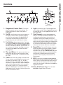 5
5
-
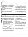 6
6
-
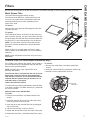 7
7
-
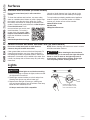 8
8
-
 9
9
-
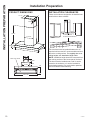 10
10
-
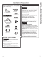 11
11
-
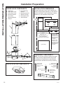 12
12
-
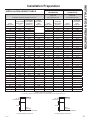 13
13
-
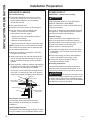 14
14
-
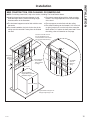 15
15
-
 16
16
-
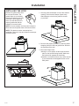 17
17
-
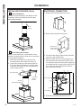 18
18
-
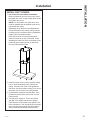 19
19
-
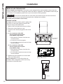 20
20
-
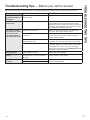 21
21
-
 22
22
-
 23
23
-
 24
24
-
 25
25
-
 26
26
-
 27
27
-
 28
28
-
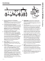 29
29
-
 30
30
-
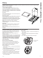 31
31
-
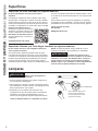 32
32
-
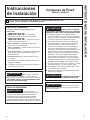 33
33
-
 34
34
-
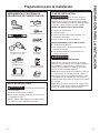 35
35
-
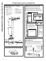 36
36
-
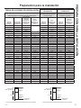 37
37
-
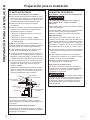 38
38
-
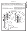 39
39
-
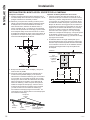 40
40
-
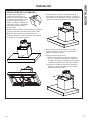 41
41
-
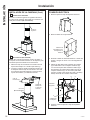 42
42
-
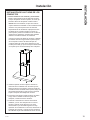 43
43
-
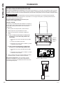 44
44
-
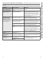 45
45
-
 46
46
-
 47
47
-
 48
48


GE UVW9301BLTS Guía de instalación
- Categoría
- Campanas de cocina
- Tipo
- Guía de instalación
En otros idiomas
- English: GE UVW9301BLTS Installation guide
Documentos relacionados
-
GE Profile UVW8304SPSS El manual del propietario
-
GE Appliances UVW8301SLSS El manual del propietario
-
GE PVW7301EJES Guía de instalación
-
-
-
GE Profile JVW5301SJSS Guía de instalación
-
GE Appliances JVW5301SJSS Guía de instalación
-
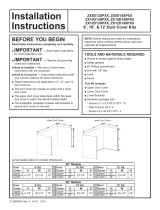 GE Appliances ZX8D14SPSS Guía de instalación
-
-

Otros documentos
-
Monogram UVW8361SLSS Guía del usuario
-
Samsung NK30N7000UG/AA El manual del propietario
-
-
Samsung NK36K7000WS Manual de usuario
-
GE Profile UVW93642PSS El manual del propietario
-
Caf CVW9304 El manual del propietario
-
-
-
Zephyr GU5/MR16 Manual de usuario
-
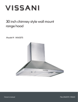 Vissani WA0575 Manual de usuario
