Frigidaire FTFB4000GS0 Guía de instalación
- Tipo
- Guía de instalación

Full Size Tumble Action Washers
Before beginning installation, carefully read these instructions. This will simp#fy the
installation and ensure the washer is installed correctly and safely. Leave these instructions
near the washer after installation for future reference.
NOTE: The electrical service to the washer must conform with local codes and ordinances
and the latest edition of the National Electrical Code, ANSI/NFPA 70.
For your safety the information in
this manual must be followed to minimize the risk
of fire or explosion or to prevent property damage,
personal injury or loss of life.
Do not store or use gasoline or other flammable
vapors and liquid in the vicinity of this or any
other appliance.
WHAT TO DO IF YOU SMELL GAS
. Do not try to light any appliance.
. Do not touch any electrical switch; do not
use any phone in your building.
. Clear the room, building or area of all
occupants.
. Immediately call your gas supplier from a
neighbor's phone. Follow the gas suppliers
instructions.
. If you cannot reach your gas supplier, call
the fire department.
Installation and service must be performed by a
qualified installer, service agency or the gas
supplier.
Printed in U.S.A.
Contents
SUBJECT PAGE
Pre-lnstallation Requirements 2
Electrical Requirements 2
Grounding Requirements 2
Water Supply Requirements 2
Drain Requirements 2
Rough-in Dimensions S
Location Of YourWasher 4
Unpacking 4
Installation 5-6
Replacement Parts 6
P/N 134849300 (0701)

PRE-INSTALLATION REQUIREMENTS
Tools Required for Installation:
1. Phillips screwdriver
2. 10 mm socket with ratchet.
3. Channel-lock adjustable pliers.
4. Carpenter's level.
absence of local codes, with the National Electrical
Codes, ANSI/NFPA 70 (latest edition). If in doubt,
call a licensed electrician. DO NOT cut off or alter
the grounding prong on the power supply cord. in
situations where a two-slot receptacle is present,
it is the owner's responsibility to have a licensed
electrician replace it with a properly grounded
three prong grounding type receptacle.
ELECTRICAL REQUIREMENTS
WATER SUPPLY REQUIREMENTS
CIRCUIT- individual, properly polarized and grounded
15 amp. branch circuit fused with 15 amp. time delay
fuse or circuit breaker.
POWER SUPPLY- 2 wire, with ground, 120 volt, single
phase, 60 Hz, Alternating Current. NOTE: Because of
potential inconsistent voltage capabilities, the useof this
washer with power created by gaspowered generators,
solar powered generators, wind powered generators or
any other generator other than tile local utility company
isnot recommended.
OUTLET RECEPTACLE - Properly grounded 3-prong
receptacle to be located so the power supply cord is
accessible when the washer is in an installed position.
NOTE: GFI (Ground Fault interrupter) receptacle is not
required.
GROUNDING REQUIREMENTS
Improper connection of the equipment
grounding conductor can result in a risk of electrical
shock. Check with a licensed electrician if you are in
doubt asto whether the appliance isproperly grounded.
1.
The washer MUST be grounded. In the event of
malfunction or breakdown, grounding will reduce
the risk of electrical shock by a path of least
resistance for electrical current.
2.
Sinceyour washer isequipped with a power supply
cord having an equipment-grounding conductor
and a grounding plug, the plug MUSTbe plugged
into an appropriate, copper wired receptacle that
is properly installed and grounded in accordance
with all local codes and ordinances or in the
Hot and cold water faucets MUST be installed within
42 inches (107 cm) of your washers water inlet. The
faucets MUST be 3/4 inch (1.g cm) garden hose type
so inlet hoses can be connected. Water pressure MUST
bebetween 30 and 120 pounds persquareinch (maximum
unbalance pressure, hot vs. cold, 10 psi.) Your water
department can advise you of your water pressure.
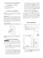
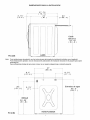
DRAIN REQUIREMENTS
I. Drain capable of eliminating 17 gals (64.3 L) per
minute.
2. A standpipe diameter of I-I/4 in. (3.18 cm)
minimum.
3. The standpipe height above the floor should be:
Minimum height: 24 in. (61 cm)
Maximum height: 96 in. (244 cm)
o oo
BACK
I
I
I
iiiiiii!_!ii_i!!i
f
96 in.
(244 cm)
Max.
NOTE:
Drain hose attached to the washer can reach a go
in. (229 cm) high standpipe. For higher standpipe,
use hose P/N 134369410, available from an
authorized parts distributor.
2

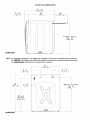
ROUGH-IN DIMENSIONS
27.75
....................................... .4
(70.5)
3.75"
(9,5)
inches(cm)
24 '_
(61)
[ I
, r
__
_ i i i i
i i i
i i i
I / i i
I
I
i : /i
/
/ !
Power Cord
33.40
(84 8)
60 _
( 1 52.4 )-!
]
i!
NOTE: For 9edestal installations, see additional installation instructions included with the pedestal
For stacking installations, see additional instaHtion instructions included with the stacking kit.
For under counter installations, no special top is required.
{ 2:i ,6 )
2 7"
...........................................{68o_;) ............................................
6,75 ....
, it............._ 17, _)
i ii
_9! 3)
2 o75
32_ 25
_81 9)
[

LOCATION OF YOUR WASHER
DO NOT INSTALL YOUR WASHER:
1. In an area exposed to dripping water or outside weather 4.
conditions. The ambient temperature should neverbe below
60°F(15.6°C)forproperwasher(deterg entbreakdown) 5.
operation.
2. In an area where it will come in contact with curtains or
drapes. 6.
3. Inan area (garage or garage-type building) where gasoline
of other flammables are kept or stored (including
automobiles).
4. On carpet. Floor MUST be solid with a maximum slope of
1/2 in. per foot (1.27 cm per 30.5 cm). Toensure vibration 7.
or movement does not occur, reinforcement of the floor
may be necessary.
IMPORTANT
MINIMUM INSTALLATION CLEARANCES
When installed in alcove or closet:
Sides, Rear = 0 in. (0 cm/
Top = 0 in. (0 cm)
When installed in closet: Front = 1 in. (2.54 cm)
Closet door ventilation required: 2 Iouvered openings each 60
in2(387 cm_),3 in. (7.6 cm) from top and bottom of door.
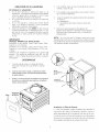
UNPACKING
1. Cut the shipping carton along the dotted line along the
bottom. Remove the carton.
2. Using a rug, blanket or piece of cardboard to protect the
floor, lay the washer on it's back.
3. Remove and savethe styrofoam base and shipping plug.
Shipping
Base Plug
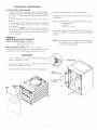
Carefully return the washer to an upright position.
Carefully move the washer to within 4 feet (122cm) of the
final location.
Remove the following from the back panel of the washer:
4 shipping bolts,
4 spacers,
1 metal "P" damp.
Remove the 4 plugs from the literature pack located in the
drum and install them in the holesvacated by the packaging
spacers.
NOTE: If the washer isto be transported at a later date,
the shipping support hardware must be reinstalled
to prevent shipping damage.
_emove:
metal "P"
4 shipping bolts,
4 spacers,
4

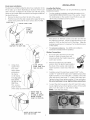
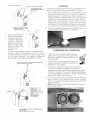
Drain Hose Installation
The drain hose isfield installed to allow hose orientation to the
left or right, up or down depending on location of the house
drain• The hose is shipped in the washer tub with the spring
clamp on the coupler elbow and drain hose hanger installed on
the end of the hose•
I. Remove the drain hose from the tub of the washen
2. Pushthe hoseonto the drain coupler at the upper left of the
washer back panel until the hose contacts the STOPRIB.
STOP RIB-
- DRAIN HOSE TABS
SPRING
CLAMP
PROVIDED
ON HOSE
I
J
f
PUSH HOSE ONTO
COUPLER TO STOP RIB
3.
Using pliers,
squeeze the
ears of the
spring clamp ..........
and position /z
the clamp
so the clamp
ears align with
and contact
the tabs on the,
drain hose• '
\
This assures \
proper location
of the clamp to prevent le_
-ALIGN SPRING
CLAMP EARS WITH
TABS ON HOSE
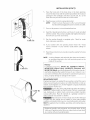
INSTALLATION
Zeve/in# the Washer
Excessive noise and vibration can be prevented by properly
leveling the washer•
1.
For free standing installation and with the washer in it's
final position, place a level on top of the washer• Adjust
the leveling legs so the washer is level front-to-rear and
side-to-side, and stable corner-to-corner.
Press down on alternate corners and sides and feel for
the slightest movement• Adjust the appropriate leg so the
washer is SOLID on the floor on ALL four legs. Keep the
leveling legextension at a minimum for best performance
of the washer.
",, 2. Forpedestal installations, See additional installation
, instructions included with the pedestal.
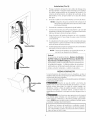
Washer Connections
1. Run some water from the hot and cold
faucets to flush the water lines and
remove particles that might clog up the
water valve screens•
2. Remove the inlet hoses and rubber
washers from the plastic bag located in
the drum of the washer and install the
rubber washers in each end of the inlet
hoses•
3.
Carefully connect the inlet hose marked "HOT" to the
outside "H" outlet of the water valve•Tighten by hand, then
tighten another 2/3 turn with pliers. Carefully connect the
other inlet hose to the inside "C" outlet of the water valve•
Tighten by hand, then tighten another 2/3 turn with pliers•
Do not crossthread or over-tighten these connections.
4. Connect the inlet hose ends to the HOTand COLD water
faucets tightly by hand, then tighten another 2/3 turn with
pliers. Turn the water on and check for leaks•
NOTE: Use only new hoses•
AL_AY@ALIGN _LA_P &&R8
5

\
Cable Tie
Cable Tie
Cable Tie
INSTALLATION (CON'T)
5.
Place the hook end of the drain hose in the drain opening.
Securethe drain hosewith the cabletie (provided inthe enclosure
package) to the standpipe, inlet hose, laundry tub, etc. so the
hose does not pull out from the force of the water.
6. Plug the power cord into a grounded outlet.
NOTE: Check to ensure the power isoff at acircuit breaker/
fuse box before plugging the power cord into an outlet.
7. Turn on the power at a circuit breaker/fuse box.
8. Read the Operating Instructions and Owner's Guide provided
with the washer. They contain valuable and helpful information
that will save you time and money.
9. Run the washer through a complete cycle. Check for water
leaks and proper operation.
I0. If your washer does not operate, please review the "Avoid
Service Checklist" in your Owner's Guide before calling for
service.
11. Placethese instructions in a location near the washer for future
reference.
NOTE: A wiring diagram and technical data sheet are located in
an envelope attached to the left hand side panel on the
inside of the washer.
Pedestal
A pedestal accessory, Model No. NLPWD15 (White),
NLPWD15GB (Glacier Blue), NLPWD15P (Platinum) and
NLPWD15E (Black), specifically designed for this washer may be
used when elevating the washer for easeof use. Failureto use
accessoriescertified by the manufacturer could result in personal
injury, property damage or damage to the washer.
REPLACEMENTPARTS
If replacements parts are needed for your washer, contact the source
where you purchased your washer, call 1-$00-944-9044, orvisit our
website, www.frigidaire.com, for the FrigidaireCompany Authorized
Parts Distributor nearest you.
Destroy the carton and plastic bags after the washer is
unpacked. Children might use them for play. Cartons covered with
rugs, bedspreads, or plastic sheets can become airtight chambers
causing suffocation. Place all materials in a garbage container or
make materiaZ inaccessible to children.
_The instructions in this manual and all other literature
included with this washer are not meant to cover every possible
condition and situation that may occur.Good safe practiceand caution
MUST be applied when installing, operating and maintaining any
appliance.
Maximum benefits and enjoyment are achieved when all the
Safety and Operating instructions are understood and practiced
asa routine with your laundering tasks.

m
instrucc on
la instalad6n
Lavadora de acci6n giratoria de tama o grande
Antes de comenzar la instalaci6n, lea estas instrucciones con atenci6n. Le facilitar2n la
instalaci6n y aseguraran que la lavadora sea instalada correctamente y de manera segura.
Guarde estas instrucciones cerca de la lavadora una vez terminada la instalaci6n para
referirse a elias en el futuro.
NOTA: el suministro electrico de su lavadora debe estar conforme con los c6digos y
ordenanzas locales y la edition m2s reciente del National Electrical Code (C6digo El_ctrico
National), ANSI/NFPA 70.
Para su seguridad, siga la
informaci6n contenida en este manual para
minimizar el riesgo de incendio o explosi6n o
para evitar daflos materiales, lesiones
personales o la muerte.
- No guarde ni utilice gasolina u otros vaporesy
liquidos inflamables en las cercanias de este
ni cualquier otro electrodom_stico.
- QUE HACER SI NOTA UN OLOR A GAS:
No trate de encender ningt_n
electrodomestico.
No toque ningOn interruptor el_ctrico; no
use ningOn tel_fono de su edificio.
Haga que todo el mundo salga del cuarto,
edificio o _qrea.
Llame inmediatamente al proveedor del
gas desde el telefono de un vecino. Siga
las instrucciones del proveedor del gas.
Si no puede ponerse en contacto con el
proveedor del gas, Ilame a los bomberos.
La instalaci6n y el servicio deben ser hechos por
un instalador capacitado, una agencia de servi-
cios o el proveedor del gas.
hnpreso en los EE.UU.
Indice
TITULO PAGINA
Requisitos antes de la instalaci6n 2
Requisitos electricos 2
Requisitos para la toma de tierra 2
Requisitos para el suministro de agua 2
Requisitos para el drenaje 2
Dimensiones para la instalacion 3
Ubicacion de su lavadora 4
Desempaque 4
Instalaci6n el Tubo de Drenaje 4-5
Instalaci6 5-6
Piezasde repuesto 6
P/N 134849300 (0701)

REQUISITOS ANTES DE LA INSTALACION
Herramientas necesarias para la instaladon:
1. DestorniNador Phillips
2. Casquillocontrinquetede lOmm
3. ANcatesajustablesChannel-lock
4. Niveldecarpintero
REQUISITOS ELECTRICOS
CIRCUITO - Circuito derivado individual, correctamente
polarizado ycon toma de tierra, de 15 amperios con fusible
de 15 amperios con retardo o disyuntor.
AL#MENTAC#ON ELECTRICA - Corriente alterna
monof_isica, 60 Hz, 120 voltios, bifilar, con toma de tierra.
NOTA:Elusodel lavadora con energfa de generador de gas,
generador de solar, generador de viento, o cualquier otros
generador con exception de le central electrica no es
recomendar.
TOMACORR#ENTES - Eltomacorrientes con 3 orificios y
toma detierra correcta, debe estarubicado de maneraque
el cable electrico sea accesible cuando la lavadora este
instalada.NOTA:GFl(Ground FaultInterrupter) receptaculo
no esrequerido.
REQUISITOS PARA LA TOMA DE TERRA
Laconexi6n incorrectadelconductor
de toma de tierra de este equipo puede causar un riesgo
de descargas el_ctricas. Consulte a un electricista
Ncenciadosinoest.1segurosiel electrodorn_stico estabien
conectado atierra.
1. Lalavadora DEBEser conectada aunatoma detierra.
Encasode un malfuncionamiento ouna faNa,latoma
de tierra reduce el riesgo de descargas electricas
proporcionando a la corriente electrica una via con
menos resistencia.
2.
Ya que su lavadora esta equipada con un cable
electrico que Nevaun conductor paratoma detierra y
un enchufe para toma de tierra, el enchufe DEBEser
insertado en un tornacorrientes adecuado, con hilos
de cobre, que este instalado yconectado atierra
segun todos losc6digos yordenanzas locales, o sino
existen c6digos locales, con los National Electrical
Codes(C6digos ElectricosNacionales),ANSI/NFPA70
(la edicion mas reciente). Sino est.1seguro, Namea
un electricista licenciado. NO corte ni modifique la
clavija de toma de tierra del cable electrico. Encasos
en que s61ohaya un tomacorrientes de dos orificios,
ser_iresponsa-bilidad del propietario hacer que un
electricista NcenciadoIocambie pot untomacorrientes
de 3 orificios con la toma de tierra adecuada.
REQUISITOS PARA EL
SUMINISTRO DE AGUA
Las Ilaves de agua caliente y fria DEBEN estar
instaladas a menos de 42 pulgadas (107 cm) de la toma
de agua de la lavadora. LasNavesDEBEN ser del tipo
manguera dejardln de 3/4 de pulgada (1,9 cm) para que
se les puedan conectar lostubos de entrada de aguaLa
presiOn del agua DEBE estar entre I0 y 120 Nbraspor
pulgada cuadrada (presion m_ixima de desequilibrio,
caliente contra fria, 10 libras por pulgada cuadrada). Su
compar]la de suministro de agua puede decirle cual es
la presion del agua.
REQUISITOS PARA EL DRENAJE
1. Drenaje que pueda eliminar 17 galones (64,3 L)por
mlnuto.
2. Di_imetro de la tuberia vertical de I-1/4 pulgadas
(3,18 cm) como minimo.
3. La altura de la tubeda vertical por encima del piso
debeser:
Altura minima: 24 pulgadas (61 cm)
Altura m_ixima:96 pulgadas (244 cm)
PARTE
T
96pulg
(244 cm)
Max.
NOTA: El tubo dedrenaje conectado a la lavadora puede
Ilegara unatuberia vertical de 90 pulgadas(229 cm). Para
una tuberfa vertical masalta, use el tubo con N° de pieza
134369410, disponible en
distribuidores autorizados de piezas.
2

DIMENSIONE5 PARA LA INSTALAqON
PO(cM)
27. 75
(70.5)
3. 75' ......................................................................24"
(9.5) (61)
iIi
\ .................. ¢ _\................. I
LADO
60"
i
(152-4) I
Cable
EI6ctdco
:33 . 40
(84.8)
J
Nota:
Para instalaciones de pedestal, vea las instrucciones adicionales de instalaci6n incluidas con el pedestal.
Para instalaciones apiladas, vea las instrucciones adicionales de instalaci6n incluidas en el paquete para apilar
(stacking kit)
Para instalaciones debajo de una mesa o base, no se requiere ninguna tapa o cubierta especial.
-........................................{ e8,6 ) .............................................
8 °5 6,75
!
91 3 )
i i_,/_'/_¸¸ ........................................... ,% ,L
DRENAJE
32,25'
i 81 , g)
PARTE POSTERIOR
Entradas de agua
33,5
(85° _
PO (CM)
J

UBICACION DE SU LAVADORA
NO INSTALE SU LAVADORA:
1. En un area expuesta a goteos de qgua o a la
intemperie. Latemperature ambiente nunca deber_i
estar per debajo de los 60 grades F (15,6 C) para
que su lavadora funcione correctamente.
2. En un area donde estara en contacto con persianas
o cortinas.
3. En un area (garaje o construction similar) donde
haya o se almacene gasolina u otros productos
inflamables (inclusive automOviles).
4. Sebre una alfombra. El pise DEBEser duro con una
incJinaciOn maxima de 1/2 pulgaga per pie (1,27 cm
per cada 30,5 cm). Paraasegurarse de que no existan
vibraciones ni ruidos, puede ser necesario reforzar
el pise.
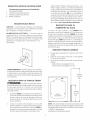
IMPORTANTE
DESPEJES MINIMOS DE INSTALAC!ON
Instalaci0n en una alcoba: Lades, Parte Trasera, Parte
Superior = 0 cm (0 pulg.)
JnstaJaciOnen un armario: Lades, Parte Trasera, Parte
Superior = 0 cm (0 pulg.), Parte Dehntera = 2.54 corn
(1 pulg.)
Aberturas de ventilaciOn requeridas en Japuerta del
armario: Dos rejillas de ventilaciOn cada 387 cm2 (60
pulg?) - 7.6 cm (3 pulg.) desde la parte inferior y superior
de la puerta.
DESEMPAQUE
1. Corte la caja de carton a Io largo de la linea
punteada al fondo de la caja. Retire la caja de
carton,
2. Usando una manta, cobija o cubierta de cart6n
para proteger el piso, recueste la Iavadora sobre
su parte trasera.
3. Retire y conserve la base de ptastico del empaque
de envio y su extension que sujeta y va hasta el
tambor de IaIavadora.
Empaque
Base de Envio
4. Con cuidado, vuelva a co[ocar [a lavadora en posicion
vertical y saque la caja.
5. Con cuidado, mueva [alavadora a unos 4 pies (122cm)
de su ubicacion definitiva.
6.
Saque [osiguiente de la parte posterior de [alavadora:
•' 4 pernos
, 4 separadoles
• I abrazaderas de presion a liberar cordon del
servicio
7.
Quite los 4 tapons pequet_os del agujero deJ
paquete de la literatura e instalelos en los agujeros
del panel lateral desocupados per el fijaciene de
empaquetade.
NOTA; En case de que la lavadora tiene que estar
transpertada en el future, esnecesarie que vuelva a instalar
]aquincalla de lafijacion de expedition para empedir daf_os
a la lavadora durante la expedition.
Cable
Quite:
abrazaderas
de"P',
4 pernos,
4
Instaladon el Tube de Drenaje
La tube de drenajees campo instalado para permitir la
orientaciOn de la tube el aJizquierdo o derecho, encima o
abajo dependiendo de la localization del dren de la casa.
La tube se envia en la tina de la lavadora con la abrazadera
del resorte en la suspension de la tube del code y de drenaje
del acoplador instalada en el extreme de la tube.
4

I.
2.
3.
COSTILLA DELAPARADA.
-OREJAS DE TUBO DE DRENAJE.
LA ABRAZADERA DEL
-, ERESORTE PROPORCIONO
EMPUJE LATUBO SOBRE EL
ACOPLADOR PARA
PARAR LA COSTILLA.
Quite latubo de drenaje
de la tina de la lavadora.
Empuje la tubo sobre
ehcoplador del drenen
el altoala izquierda
del panel de la lavadora
detr_s hasta que la tubo
entra en contacto con la
COSTILLAde la
PARADA.
//
\
Con los alicates, expdma los o[dos de la abrazadera del
resorte y coloque la abrazadera asi que los oidos de
abrazadera alinean con yentran en contacto con las orejas
en la de tubo de drenaje. Esto asegura la localization
apropiada de la abrazadera para prevenir los escapes.
ALINEE LOS OiDOS DE ABRAZADERA DEL RESORTE
CON LAS OREJAS EN LA TUBO.
OREJAS
/
?_ ORIENTE LA TUBO A
DERECHO, A
LA IZQUEERDA, ENCIMA
DE O ABAJO
SEGUN LO NECESITADO
ANTES
DE COLOCAR LA
ABRAZADERA EN
LA POSICION
Instalacion
LanivelaciOn del ruido y de lavibration excesivosde la hvadora
puede ser prevenida correctamente nivelando la lavadora.
1. Para la instalaciOn derecha libre y con la lavadora en ella
esta la position final, pone un nivel encima de la lavadora.
Ajuste las piernas de nivelaciOn asi que la lavadora es, y
esquina-a-esquina estable de adelante hacia atras y de lado
a lado liana. Presione abajo en esquinas y lados alternos y
sientase para el movimiento mas leve. Ajuste la pierna
apropiada asi que la arandela es SOLIDA en el piso en las
cuatro piemas. Guarde la extension de nivelaciOn de la pierna
en un minimo para el mejor funcionamiento de la lavadora.
2. Para las instalaciones del pedestal, vea las instrucciones de
instaladOn adicionales induidas con el pedestal.
CONEXIONES DE LA LAVADORA
1. Dejecorrer un poco agua de lasIlavesde agua
caliente y fria para vaciar las Iineasy eliminar las
particulas quepueden obstruir las rejillas de las
valvulas de agua.
2. Examine los tubos de entrada de agua para
asegurarse de que lasarandelas de caucho est@n
instaladas en cada extremo.
3. Conecte con cuidado lostubos de entrada a lavalvula
de agua (en la lavadora)CALIENTEcon de salida "H",
apriete a mano y kJegoapriete 2/3 de vuelta con unosalicates.
Conecte con cuidado lostubos de entrada a lavalvula de agua
(en la lavadora)FRIAcon de sdida "C ", apriete a mano y luego
apriete 2/3 de vuelta con unos alicates.
4. Conecte los extremos del tubo de entrada alas Ilaves de
agua CALIENTE y FRIA apretando bien a mano, y apriete
otros 2/3 de vuelta con losalicates. Abra el agua y compruebe
que no haya fugas.
NOTA: Utilice solamente lasnuevas mangueras provistas con
este electrodomestico.
ALINEESiEMPRE LOS OiDOS DE ABRAZADERA
DEL RESORTE
CON LAS OREJAS EN LA TUBO

_f
0
0
Sujetacables
/
Instalaci6n (Con't)
5. Ponga el extremo del gancho de la tubo de drenaje en la
abertura del dren. Asegure la tubo de drenaje con la atadura
de cables (proporcionada en el paquete del recinto) a la
columna de alimentaciOn, la tuberia de la entrada, la tina
del lavadero, el etc. asl que la tubo no sesacade la fuerza
del agua.
6. Enchufe el cable en un tomacorrientes con toma de tierra.
NOTA: Asegurese de que la corriente este cortada en el
disyuntor/caja de fusibles antes de enchufar el cable
en el tomacorrientes.
7. Encienda la corriente en eldisyuntor/caja de fusibles.
8. Lea las Instrucciones para el funcionamiento y la Guia del
propietario incluidas con la lavadora. Contienen information
valiosa y util que leahorrara tiempo y dinero.
9. Haga funcionar la lavadora durante un ciclo completo.
Compruebe que no haya fugas de agua y que funcione
correctarnente.
I0. Sisulavadora nofunciona, leala "Lista de comprobaciOn para
evitar el servicio" que seencuentra en la Guia del propietario,
antes de Ilamar al servicio tecnico.
11. Guarde estasinstrucciones en un lugar cercano a la lavadora
para poder referirse aelias en el futuro.
NOTA: Dentro de la lavadora, en el panel de servicio, se
encuentra un diagrama de cableado.
Pedestal
Un accesorio del pedestal diseF_0,Numero de Modelo
NLPWD15 (Blanco), NLWD15P(Platino), NLWDI5GB
(Azul Glaciar) o NLWD15E (Negro), especificarnentepara
esta lavadora puede ser utilizado al elevar la lavadora para
la facilidad de empleo. La falta de utilizar los accesorios
certificados por el fabricante podia dar lugar a dailos cor-
porales, a daflos materiales, o a dar_oa la lavadora.
PIEZAS DE REPUESTO
Si necesita piezas de repuesto para su lavadora, acuda al
establecimientodonde lacompr6 Ilameal 1-800- 944-9044,ovisite
nuestro web sitio,vwvw.frigidaire.
com,para ladigan Distribuidor autorizada de laspiezasdeFrigidaire
Iom_s cerca posible usted.
Deseche la caja de carton y las bolsas de
pl_%ticouna vez que haya desembalado la lavadora. Los ninos
podrian usarlas para jugan Las cajas de carton tapadas con
alfombras, colchas u hojas de plastico pueden convertirse en
cSmaras hermeticas, causando asfixia. Coloque todos los
materiales en el basurero o evite que los nif_ostengan accesoa
ellos.
Lasinstrucciones que aparecen en este manual
y las demas guias induidas con esta lavadora no pretenden
cubrir todas lascondiciones y situaciones posibles que pueden
ocurrir. DEBEtenerse sentido comun y cuidado al instalar,operar
mantener cualquier electrodom(_stico.
Se obtiene el mSximo de beneficios y resultados cuando
todas las instrucciones de seguridad y de funcionamiento
son comprendidas y puestas en practica de forma rutinaria
cada vez que se lava la ropa.
6
-
 1
1
-
 2
2
-
 3
3
-
 4
4
-
 5
5
-
 6
6
-
 7
7
-
 8
8
-
 9
9
-
 10
10
-
 11
11
-
 12
12


Frigidaire FTFB4000GS0 Guía de instalación
- Tipo
- Guía de instalación
en otros idiomas
Artículos relacionados
-
Frigidaire LTF2940ES3 Guía de instalación
-
-
-
Frigidaire LTF2940FE1 Guía de instalación
-
-
Frigidaire LTF8000FE0 Guía de instalación
-
-