
D28490, D28491
Esmeriladora Angular
Angle Grinder
INSTRUCTIVO DE OPERACIÓN, CENTROS DE SERVICIO Y PÓLIZA DE
GARANTÍA. ADVERTENCIA: LÉASE ESTE INSTRUCTIVO ANTES DE USAR EL
PRODUCTO.
MANUAL DE INSTRUCCIONES
INSTRUCTION MANUAL
¿Dudas? Visítenos en Internet: www.dewalt.com
Questions? See us on the World Wide Web at www.dewalt.com


1
Español
Defi niciones: Normas
de seguridad
Las siguientes definiciones describen el nivel de gravedad de
cada advertencia. Lea el manual y preste atención a estos
símbolos.
PELIGRO:
Indica una situación de peligro inminente que, si no se
evita,
provocará
la
muerte o lesiones graves.
ADVERTENCIA:
Indica una situación de peligro potencial que, si
no se evita,
podría
provocar la
muerte o lesiones graves.
ATENCIÓN:
Indica una situación de peligro potencial que, si no
se evita,
puede
provocar
lesiones leves o moderadas.
AVISO:
S
e refi ere a una práctica no relacionada a lesiones
corporales que de no evitarse puede resultar en daños a la
propiedad.
ADVERTENCIA: para reducir el riesgo de lesiones, lea el
manual de instrucciones.
Advertencias generales de seguridad
para las herramientas eléctricas
ADVERTENCIA: Lea todas las advertencias de seguridad
e instrucciones. El incumplimiento de las advertencias o
instrucciones puede provocar descargas eléctricas, incendios o
lesiones graves.
GUARDE LAS ADVERTENCIAS E
INSTRUCCIONES PARA PODER
CONSULTARLAS EN EL FUTURO
El término “herramienta eléctrica” incluido en todas las advertencias se
refiere a su herramienta eléctrica conectada a la red (cable eléctrico)
o a su herramienta eléctrica accionada con baterías (inalámbrica).
1) SEGURIDAD DEL ÁREA DE TRABAJO
a) Mantenga el área de trabajo limpia y bien iluminada. Las
áreas abarrotadas u oscuras propician accidentes.
b) No haga funcionar las herramientas eléctricas en
atmósferas explosivas, como ambientes donde haya
polvo, gases o líquidos inflamables. Las herramientas
eléctricas originan chispas que pueden encender el polvo o
producir humo.
c) Mantenga alejados a los niños y a los espectadores
de la herramienta eléctrica en funcionamiento. Las
distracciones pueden provocar la pérdida de control.
2) SEGURIDAD ELÉCTRICA
a) Los enchufes de la herramienta eléctrica deben
adaptarse a la toma de corriente. Nunca modifique el
enchufe de ninguna manera. No utilice ningún enchufe
adaptador con herramientas eléctricas con conexión a
tierra. Los enchufes no modificados y que se adaptan a las
tomas de corrientes reducirán el riesgo de descarga eléctrica.
b) Evite el contacto corporal con superficies con toma de
tierra como, por ejemplo, tuberías, radiadores, cocinas
y refrigeradores. Existe mayor riesgo de descarga eléctrica
si su cuerpo está puesto a tierra.
c) No exponga las herramientas eléctricas a la lluvia ni a
condiciones de humedad. Si entra agua en una herramienta
eléctrica, aumentará el riesgo de descarga eléctrica.
d) No use el cable indebidamente. Nunca utilice el cable
para transportar, tirar o desenchufar la herramienta
eléctrica. Mantenga el cable alejado del calor, el aceite,
los bordes afilados o las piezas móviles. Los cables
dañados o enredados aumentan el riesgo de descarga
eléctrica.
e) Al operar una herramienta eléctrica en el exterior, utilice
un cable prolongador adecuado para tal uso. Utilice un

2
Español
cable adecuado para uso en exteriores a fin de reducir el riesgo
de descarga eléctrica.
f) Si no se puede evitar el uso de una herramienta eléctrica
en una zona húmeda, utilice un dispositivo de corriente
residual (residual current device, RCD) de seguridad.
El uso de un RCD reduce el riesgo de sufrir una descarga
eléctrica.
3) SEGURIDAD PERSONAL
a) Permanezca alerta, controle lo que está haciendo y
utilice el sentido común cuando emplee una herramienta
eléctrica. No utilice una herramienta eléctrica si
está cansado o bajo el efecto de drogas, alcohol o
medicamentos. Un momento de descuido mientras se opera
una herramienta eléctrica puede provocar lesiones personales
graves.
b) Utilice equipo de seguridad personal. Utilice siempre
protección ocular. El uso de equipo de seguridad, como
mascarillas para polvo, calzado de seguridad antideslizante,
cascos o protección auditiva en las condiciones adecuadas
reducirá las lesiones personales.
c) Evite poner en marcha la herramienta involuntariamente.
Asegúrese de que el interruptor está apagado antes de
conectar la fuente de alimentación y/o la batería, coger
o transportar la herramienta. Transportar herramientas
eléctricas con su dedo apoyado sobre el interruptor o enchufar
herramientas eléctricas con el interruptor en la posición de
encendido puede propiciar accidentes.
d) Retire la clavija de ajuste o la llave de tuercas antes de
encender la herramienta eléctrica. Una llave de tuercas
o una clavija de ajuste que quede conectada a una pieza
giratoria de la herramienta eléctrica puede provocar lesiones
personales.
e) No se estire demasiado. Conserve el equilibrio y
posiciónese adecuadamente en todo momento. Esto
permite un mejor control de la herramienta eléctrica en
situaciones inesperadas.
f) Use la vestimenta adecuada. No use ropas holgadas ni
joyas. Mantenga el cabello, la ropa y los guantes alejados
de las piezas en movimiento. Las ropas holgadas, las joyas
o el cabello largo pueden quedar atrapados en las piezas
en movimiento.
g) Si se suministran dispositivos para la conexión de
accesorios con fines de recolección y extracción de
polvo, asegúrese de que estén conectados y que se
utilicen correctamente. El uso del extractor de polvo puede
reducir los riesgos relacionados con el polvo.
4) USO Y MANTENIMIENTO DE LA HERRAMIENTA
ELÉCTRICA
a) No fuerce la herramienta eléctrica. Utilice la herramienta
eléctrica correcta para el trabajo que realizará. La
herramienta eléctrica correcta hará el trabajo mejor, y de un
modo más seguro, a la velocidad para la que fue diseñada.
b) No utilice la herramienta eléctrica si no puede encenderla
o apagarla con el interruptor. Las herramientas que no
puedan ser controladas con el interruptor constituyen un
peligro y deben repararse.
c) Desconecte el enchufe de la fuente de alimentación o
la batería de la herramienta eléctrica antes de realizar
cualquier ajuste, cambio de accesorios o almacenar
las herramientas eléctricas. Estas medidas de seguridad
preventivas reducen el riesgo de encender la herramienta
eléctrica de forma accidental.
d) Guarde la herramienta eléctrica que no esté en uso fuera
del alcance de los niños y no permita que otras personas
no familiarizadas con ella o con estas instrucciones
operen la herramienta. Las herramientas eléctricas son
peligrosas si son operadas por usuarios que no tienen
formación.

3
Español
e) Mantenimiento de las herramientas eléctricas. Revise
que no haya piezas en movimiento mal alineadas o
trabadas, piezas rotas o cualquier otra situación que
pueda afectar el funcionamiento de las herramientas
eléctricas. Si encuentra daños, haga reparar la
herramienta eléctrica antes de utilizarla. Se producen
muchos accidentes a causa de las herramientas eléctricas que
carecen de un mantenimiento adecuado.
f) Mantenga las herramientas de corte afiladas y limpias.
Las herramientas de corte con mantenimiento adecuado y con
los bordes de corte afilados son menos propensas a trabarse
y son más fáciles de controlar.
g) Utilice las herramientas eléctricas, sus accesorios y
piezas, etc. de acuerdo con las presentes instrucciones,
teniendo siempre en cuenta las condiciones de trabajo y
el trabajo que deba llevar a cabo. El uso de la herramienta
eléctrica para operaciones diferentes de aquellas para las que
fue diseñada podría originar una situación peligrosa.
5) MANTENIMIENTO
a) Solicite a una persona cualificada en reparaciones que
realice el mantenimiento de su herramienta eléctrica
y que solo utilice piezas de repuesto idénticas. Esto
garantizará la seguridad de la herramienta eléctrica.
NORMAS ESPECÍFICAS DE SEGURIDAD
ADICIONALES
Normas de seguridad adicionales
• La esmeriladora se ha diseñado para el esmerilado y corte
de mampostería y acero.
ADVERTENCIA: No corte ni amole metales de poca densidad
con un contenido en magnesio superior al 80%, ya que este tipo de
metales son inflamables.
• No utilice accesorios distintos de las muelas y discos de
corte reforzados con fibra.
• Utilice exclusivamente muelas y discos de corte
recomendados por el fabricante.
• La velocidad máxima de la muela o del disco de corte debe
ser siempre igual o superior a la velocidad en vacío impresa
en la placa de características de la herramienta.
• No corte piezas que requieran una profundidad máxima de
corte superior a la del disco de corte.
• No utilice muelas o discos de corte que no se ajusten a las
dimensiones indicadas en la documentación técnica. No
utilice espaciadores para encajar el disco en el eje.
• Examine las muelas y los discos de corte antes de cada
uso. No utilice discos desportillados, agrietados o con otros
defectos.
• Si dispone de ellos, utilice discos abrasivos al encajar el
disco en el eje.
• Cuando instale un disco con orificio roscado, asegúrese de
que la rosca sea lo suficientemente larga para recibir el eje.
• Compruebe que la muela o el disco de corte esté
correctamente instalado antes del uso.
• Ponga en marcha la herramienta sin carga en una posición
segura durante 30 segundos como mínimo. Si se produce
una vibración excesiva o existe algún otro defecto, pare la
herramienta y examínela para descubrir la causa.
• No utilice esta herramienta sin el protector en su sitio.
• Compruebe que la pieza trabajada esté debidamente
apoyada.
• No utilice la herramienta cerca de líquidos inflamables,
gases o residuos. Las chispas o astillas calientes procedentes
de los cepillos mecánicos de corte o ruptura pueden prender los
materiales combustibles.

4
Español
• No utilice la herramienta mientras se encuentre en línea
con el disco. No permita que otras personas se acerquen el lugar
de trabajo.
• No utilice discos de corte para el esmerilado lateral.
• No utilice el bloqueo del eje mientras la herramienta está en
funcionamiento.
• Tenga cuidado al apagar la herramienta, ya que la muela o
el disco seguirá girando durante un breve periodo.
• Almacene siempre las muelas y los discos de corte en
lugares secos.
Causas de la inversión de giro y su
prevención por parte del operario
• La inversión de giro es una reacción brusca a una rueda giratoria,
una almohadilla de repuesto, un cepillo o cualquier otro accesorio
que se encuentre comprimido o esté atascado y que, a su vez,
hace que la herramienta eléctrica se descontrole y vaya en sentido
opuesto al giro del accesorio en el momento de la conexión.
• Por ejemplo, si una pieza engancha o comprime una muela o
disco abrasivo, el borde de la rueda que entra en contacto con
el punto crítico puede quedarse clavado en la superficie del
material y hacer que la rueda salga despedida. La rueda también
puede escaparse de las manos del operario, según el sentido
del movimiento de la rueda en el punto de compresión. En estas
condiciones, la muela o disco abrasivo también pueden romperse.
• La inversión de giro es el resultado de un mal uso de la herramienta
y/o de unos incorrectos procedimientos o condiciones de uso y se
puede evitar tomando las medidas de precaución adecuadas, tal
y como se indica seguidamente:
a) Sujete fuertemente la herramienta eléctrica y coloque
su cuerpo y su brazo de manera que le permita resistir
la fuerza de la inversión de giro. Utilice siempre una
empuñadura auxiliar, si la hay, para controlar mejor
la inversión de giro o la reacción del par durante el
arranque. El operario puede controlar la reacción del par o
la fuerza de la inversión de giro siempre que tome las debidas
precauciones.
b) No coloque nunca su mano cerca del accesorio giratorio.
El accesorio puede golpearle la mano.
c) No coloque su cuerpo en la zona en la que se moverá la
herramienta eléctrica, de lo contrario podría golpearle.
En caso de atascarse, la inversión de giro empujará la
herramienta en el sentido opuesto al movimiento de la rueda.
d) Tenga especial cuidado cuando trabaje curvas, bordes
afilados, etc. Evite el rebote y el enganche del accesorio.
Las curvas, los bordes afilados o los rebotes tienden a atascar
el accesorio giratorio y provocan la pérdida del control o la
inversión de giro.
e) No coloque una cuchilla para tallar madera en la sierra
de cadena ni una cuchilla de sierra dentada. Estas
cuchillas generan con frecuencia inversiones de giro y pérdidas
de control.
Advertencias específi cas para las
operaciones de esmeriladoras
a) Utilice sólo los discos recomendados para su herramienta
eléctrica y la protección de seguridad específicamente
diseñada para el disco seleccionado. Los discos que
no hayan sido diseñados para esta herramienta eléctrica no
quedarán oportunamente protegidos y no ofrecerán seguridad.
b) La protección debe quedar sujeta a la herramienta de
seguridad y estar perfectamente colocada para obtener
la máxima seguridad, de modo que el operador quede
expuesto a una mínima superficie de la herramienta. La
protección sirva para proteger al operario de los fragmentos de
disco rotos o del contacto adicional con el disco

5
Español
c) Los discos deben utilizarse sólo para las aplicaciones
recomendadas. Por ejemplo: no realice operaciones de
esmerilado con el lateral del disco de corte. Los discos de
cortar han sido diseñados para los esmerilados periféricos, por
lo que las fuerzas laterales aplicadas a estas muelas o discos
podrían hacer que se partieran.
d) Utilice siempre flanges que no estén dañadas, que
tengan el tamaño y la forma correctas para el disco
seleccionado. Unos flanges adecuados para el disco sujetan
la disco y así reducen la posibilidad de su rotura. Los flanges
para los discos de corte pueden ser distintas a los flanges para
las discos.
e) No utilice discos gastados de herramientas eléctricas
más grandes. Los discos diseñados para una herramienta
eléctrica más grande no resultan adecuados para la mayor
velocidad de una herramienta más pequeña y podrían
quemarse.
Advertencias específi cas para las
operaciones de cepillado metálico
a) No olvide que el cepillo desprende cerdas metálicas
durante su funcionamiento habitual. No sobrecargue
los alambres mediante la aplicación de una carga
excesiva en el cepillo. Las cerdas metálicas pueden penetrar
fácilmente en ropas ligeras y/o en la piel.
b) Si se recomienda el uso de una protección para el
cepillado metálico, no permita ninguna interferencia
de la rueda metálica o del cepillo metálico con la
protección. La rueda metálica o el cepillo metálico pueden
sufrir un aumento en su diámetro debido al trabajo y a las
fuerzas centrífugas.
Advertencias de seguridad adicionales
para esmeriladoras
• Los orificios de ventilación suelen cubrir piezas en
movimiento, por lo que también se deben evitar. Las piezas
en movimiento pueden atrapar prendas de vestir sueltas, joyas o
el cabello largo.
• El cable de extensión deben ser de un calibre apropiado
para su seguridad. Un cable de un calibre insuficiente causará
una caída en la tensión de la línea dando por resultado una pérdida
de energía y sobrecalentamiento. Cuando se utilice más de un
alargador para completar el largo total, asegúrese que los hilos
de cada alargador tengan el calibre mínimo. La tabla siguiente
muestra el tamaño correcto a utilizar, dependiendo de la longitud
del cable y del amperaje nominal de la placa de identificación. Si
tiene dudas sobre cuál calibre usar, use un calibre mayor
Tensión (Voltios) Longitud del cable en metros (m)
120–127 V 0–7 7–15 15–30 30–50
220–240 V 0–15 15–30 30–60 60–100
Corriente
nominal
(Amperios)
Sección nominal mínima del cable en
milímetros cuadrados (mm
2
)
0–6 A 1,0 1,5 1,5 2,5
6–10 A 1,0 1,5 2,5 4,0
10–12 A 1,5 1,5 2,5 4,0
12–16 A 2,5 4,0 No recomendado
ADVERTENCIA: Si el enchufe o el cable de alimentación están
dañados lo debe reemplazar el fabricante o su representante o por
una persona igualmente calificada para evitar peligro.
ADVERTENCIA: Use SIEMPRE lentes de seguridad. Los
anteojos de diario NO SON lentes de seguridad. Utilice además
una cubrebocas o mascarilla antipolvo si la operación de corte
genera demasiado polvo. SIEMPRE LLEVE EQUIPO DE SEGURIDAD
CERTIFICADO:

6
Español
• Protección ocular ANSI Z87.1 (CAN/CSA Z94.3),
• Protección auditiva ANSI S12.6 (S3.19),
• Protección respiratoria NIOSH/OSHA/MSHA.
ADVERTENCIA: Parte del polvo generado al lijar, serrar, esmerilar
y taladrar, así como al realizar otras actividades del sector de la
construcción, contienen productos químicos que pueden producir
cáncer, defectos congénitos u otras afecciones reproductivas.
Algunos ejemplos de estos químicos son:
• plomo de algunas pinturas en base a plomo,
• polvo de sílice proveniente de ladrillos y cemento y otros
productos de albañilería, y
• arsénico y cromo provenientes de madera tratada
químicamente.
Su riesgo de exposición a estos químicos varía, dependiendo de la
frecuencia con la cual realiza usted este tipo de trabajo. Para reducir
su exposición a estas sustancias químicas: trabaje en una zona
bien ventilada y llevando equipos de seguridad aprobados, como
mascarillas antipolvo especialmente diseñadas para filtrar partículas
microscópicas.
• Evite el contacto prolongado con polvo generado por el
lijado, aserrado, pulido, taladrado y otras actividades de
construcción. Vista ropas protectoras y lave las áreas de
la piel expuestas con agua y jabón. Si permite que el polvo
se introduzca en la boca u ojos o quede sobre la piel, puede
favorecer la absorción de productos químicos peligrosos.
ADVERTENCIA: La utilización de esta herramienta puede
generar polvo o dispersarlo, lo que podría causar daños graves
y permanentes al sistema respiratorio, así como otras lesiones.
Siempre use protección respiratoria aprobada por NIOSH (Instituto
Nacional de Seguridad y Salud en el Trabajo) u OSHA (Administración
de Seguridad y Salud en el Trabajo) apropiada para la exposición al
polvo. Dirija las partículas en dirección contraria a la cara y el cuerpo.
ADVERTENCIA: Siempre lleve la debida protección auditiva
personal en conformidad con ANSI S12.6 (S3.19) durante el
uso de esta herramienta. Bajo algunas condiciones y duraciones
de uso, el ruido producido por este producto puede contribuir a la
pérdida auditiva.
ADVERTENCIA: Utilice siempre protección para los ojos.
Todos los usuarios y espectadores deben utilizar protección para los
ojos conforme con las normas ANSI Z87.1.
ADVERTENCIA: Cuando no la utilice, coloque la esmeriladora
en una superficie estable donde no pueda moverse de manera
accidental, deslizarse ni provocar tropezones o caídas. Puede
causar lesiones personales graves.
ATENCIÓN: Para reducir el riesgo de lesiones personales, tenga
mucho cuidado al trabajar en una esquina o borde, ya que puede
producirse un movimiento repentino y violento de la herramienta si el
disco u otro accesorio entra en contacto con una segunda superficie
o un borde.
• La etiqueta de su herramienta puede incluir los siguientes
símbolos. Los símbolos y sus definiciones son los siguientes:
V ..........voltios A ........... amperios
Hz ........hertz W .......... vatios
min ......minutos
........ corriente alterna
....corriente directa
n
o ......... velocidad sin carga
........Construcción Clase I .......... terminal a tierra
(con conexión a tierra)
......... símbolo de alerta de
.........Construcción Clase II seguridad
(con aislamiento doble) …/min ... revoluciones o
BPM ....golpes por minuto reciprocidad por
sfpm ....pies superficies por minuto
............. minuto
IPM ....... impactos por minuto

7
Español
GUARDE ESTAS INSTRUCCIONES PARA
VOLVER A CONSULTAR EN EL FUTURO
Motor
Verifique que su abastecimiento de energía concuerda con lo indicado
en la placa de identificación. Disminuciones en el voltaje mayores a
10% provocarán la pérdida de potencia y sobre calentamiento.
D
EWALT realiza pruebas de fábrica en todas sus herramientas; si su
herramienta no funciona la línea de alimentación.
COMPONENTES
ADVERTENCIA: Nunca modifique la herramienta eléctrica, ni
tampoco ninguna de sus piezas. Podría producir lesiones corporales
o daños.
A. Interruptor de gatillo D. Guarda
B. Botón de encendido permanente E. Mango lateral
C. Traba del eje
A
B
D
E
C
USO PREVISTO
La esmeriladora angular de alto rendimiento fue diseñada para
aplicaciones demandantes, por ejemplo obras de construcción.
NO use la herramienta bajo condiciones de humedad o en presencia
de gases o líquidos inflamables.
NO utilice otras muelas o discos que las ruedas de centro deprimido
y discos con protección.
Estas esmeriladoras de alto rendimiento son herramientas
profesionales. NO permita que los niños tengan contacto con la
herramienta. Cuando la hagan funcionar operarios sin experiencia, es
necesaria su supervisión.
Características
INTERRUPTOR
La herramienta se controla con un gatillo de interrupción (A). El botón
de encendido permanente (B) proporciona mayor comodidad en las
aplicaciones de uso prolongado.
POSICIONES MÚLTIPLES DEL MANGO LATERAL
El mango lateral puede colocarse en 2 posiciones según la preferen-
cia del operario y la aplicación. El mango lateral se debe utilizar
siempre para mantener la herramienta bajo control.
TRABA DEL EJE
La traba del eje previene que el eje gire
C
mientras se instalan o se retiran los discos.
Ajuste el pasador de la traba del eje
únicamente cuando la herra mienta esté
apagada y desconectada de la toma de
corriente. Para accionar el seguro. Para
accionar la traba del eje, oprima el botón
del seguro (C) y gire el eje hasta topar.
NOTA: Nunca oprima el botón para traba del eje mientras la
esmeriladora está encendida. Nunca encienda la esmeriladora
mientras el botón de traba del eje está siendo oprimido. Esto podrá
causar daño a su herramienta.
MONTAJE
La esmeriladora está equipada con dispositivo que facilita el montaje
y la remoción de discos.

8
Español
Accesorios
Es importante seleccionar las guardas, almohadillas de respaldo
y bridas correctas para usarse con los accesorios de la esmerila-
dora. Consulte las tablas de las páginas 11–12 para seleccionar los
accesorios apropiados.
ENSAMBLAJE Y AJUSTES
ADVERTENCIA: Para reducir el riesgo de lesiones personales
graves, apague la herramienta y desconéctela de la fuente de
alimentación antes de realizar ajustes o de retirar/instalar
cualquier dispositivo o accesorio. Antes de volver a conectar
la herramienta, oprima y libere el interruptor disparador para
asegurarse de que la herramienta esté apagada. Un arranque
accidental podría causar lesiones.
Instalación del mango lateral
Para instalar el mango lateral, enrósquelo
en una de las dos posiciones y apriételo
con firmeza girándolo hacia la derecha.
OPERACIÓN
ADVERTENCIA: Respete siempre las
instrucciones de seguridad y la
reglamentación aplicable.
ADVERTENCIA: Para reducir el
riesgo de lesiones personales graves,
apague la herramienta y desconéctela
de la fuente de alimentación antes de
realizar ajustes o de retirar/instalar cualquier dispositivo o
accesorio. Antes de volver a conectar la herramienta, oprima
y libere el interruptor disparador para asegurarse de que la
herramienta esté apagada. Un arranque accidental podría causar
lesiones.
ALIMENTACIÓN DE CORRIENTE
Conecte la esmeriladora angular grande a un circuito eléctrico dedi-
cado. El operar esta herramienta en un circuito con otras herra -
mientas, resultará en un rendimiento menor.
INTERRUPTOR
ATENCIÓN: Antes de conectar la
A
B
herramienta a una toma de corriente o después
de una falla en la alimentación, oprima y suelte
el interruptor de gatillo (A) una vez sin oprimir el
botón de encendido permanente (B) para
asegurarse que el interruptor esté apagado. Si
el interruptor de gatillo tiene ajustado el seguro de operación
continua, la herramienta se encenderá inadvertidamente al conectar
de nuevo la herramienta. Sujete con firmeza el mango lateral y el
mango trasero para mejor control de la herra mienta al encenderla y al
operarla.
OPERACIÓN DEL GATILLO
Para encender la herramienta, oprima el interruptor de gatillo (A).
La herramienta permanecerá encendida mientras oprima el gatillo.
Suelte el gatillo para apagar la herra mienta.
OPERACIÓN DEL GATILLO CON EL DISPOSITIVO DE
ENCENDIDO PERMANENTE
Para encender la herramienta, oprima el gatillo. Oprima y sujete el
botón de encendido permanente (B) mientras suelta el gatillo. El
botón de encendido permanente permanecerá oprimido y la herra-
mienta permanecerá encendida.
NOTA: Permita que la herramienta alcance la velocidad máxima.
Antes de hacer contacto con la superficie de trabajo. Levante la
herramienta de la superficie de trabajo antes de apagarla.
ATENCIÓN:
Asegúrese de que el disco se haya detenido
completamente antes de poner la herramienta.

9
Español
Discos para esmerilar
montaje
guarda tipo 27
disco
tipo 27
montaje
guarda tipo 28
disco
tipo 28
montaje
guarda tipo 27
arandela
disco tipo 27
tuerca de fijación
montaje
guarda tipo 28
arandela
disco tipo 28
tuerca de fijación
NOTA: el tamaño del disco debe corresponder al tamaño de la
guarda; un disco nuevo de 180 mm (7") no se debe utilizar con
una guarda de 230 mm (9"). La superficie inferior del disco debe
permanecer adentro del borde de la guarda.
Discos de lijar
montaje
respaldo de goma
disco de lija
tuerca de fijación
Cepillos de
alambre
montaje
Disco de alambre
guarda tipo 27
montaje
Cepillo de alambre con
forma de copa
guarda tipo 27

10
Español
Copa de Piedra
guarda tipo 11
copa de piedra
arandela
copa de piedra
Discos de corte
montaje
guarda tipo 1
arandela
608370-00
disco diamantado
montaje
guarda tipo 1
arandela
disco abrasivo de corte
tuerca de fijación tuerca de fijación
Discos para lijar
montaje
montaje
guarda tipo 27
guarda tipo 27
disco para lijar
disco de lijar
tuerca de fijación
arandela
NOTA: el tamaño del disco debe corresponder al tamaño de la
guarda; un disco nuevo de 180 mm (7") no se debe utilizar con
una guarda de 230mm (9"). La superficie inferior del disco debe
permanecer adentro del borde de la guarda.

11
Español
REMOCIÓN DEL SEGURO DEL EJE
El botón del seguro del eje puede ser removido permanentemente
sin afectar la conformidad de las agencias reguladoras mostradas
en la placa de especificaciones de la herramienta. La remoción del
seguro debe ser realizada por un Centro de Servicio Autorizado
D
EWALT.
Instalación y utilización de los discos de
centro deprimido para esmerilar y de los
discos de aleta para lijar
INSTALACIÓN Y REMOCIÓN DE LA GUARDA
ADVERTENCIA: Para reducir el riesgo de lesiones personales
graves, apague la herramienta y desconéctela de la fuente de
alimentación antes de realizar ajustes o de retirar/instalar
cualquier dispositivo o accesorio. Antes de volver a conectar
la herramienta, oprima y libere el interruptor disparador para
asegurarse de que la herramienta esté apagada. Un arranque
accidental podría causar lesiones.
INFORMACIÓN IMPORTANTE
SOBRE LAS GUARDAS
Se debe utilizar guardas con todos los discos
de esmerilar, discos de lijar, ruedas y cepillos
de alambre. La herramienta se puede utilizar
sin una guarda únicamente para lijar con
discos corrientes.
ATENCIÓN
: Cuando utilice un disco
abrasivo con una guarda tipo 27, 28 o 29,
asegúrese que la superficie superior del disco
abrasivo está dentro de la guarda.
INSTALACIÓN Y REMOCIÓN DE LOS DISCOS
Los discos se instalan directamente en el eje.
1. Enrosque el disco en el eje a mano, asentándolo contra el
montaje.
2. Oprima el botón del seguro del eje y utilice una llave para apretar
el cubo del disco.
3. Invierta el procedimiento anterior para retirar el disco.
ATENCIÓN:
El no asentar apropiadamente el disco contra el
montaje antes de encender la herramienta podria ocasionar daño a
herramienta o al disco.
INSTALACIÓN DE LOS DISCOS CONCENTRO DEPRIMIDO
Los discos de centro deprimido tipo 27, se deben utilizar con las
arandelas disponibles. Para más información consulte las tablas que
aparecen de este manual.
G
E
H
1. Instale el flanje metálico de respaldo en el eje contra el
montaje.
2. Coloque el disco contra el flanje de respaldo, centrándolo en el
flanje.
3. Mientras oprime el botón del seguro del eje, enrosque la
tuerca(H).
4. Apriete la tuerca con una llave.
5. Invierta el procedimiento anterior para retirar el disco.

12
Español
ESMERILADO DE SUPERFICIES CON DISCOS
DE ESMERILAR
1. Permita que la herramienta alcance la velocidad máxima antes de
hacer contacto con la superficie de trabajo.
2. Aplique presión mínima a la superficie de trabajo, para permitir
que la herramienta funcione a alta velocidad.
3. Mantenga un ángulo de 20° a 30° entre la superficie de trabajo y
la herramienta.
4. Mueva la herramienta contínuamente hacia adelante y hacia atrás
para evitar crear marcas en la superficie de trabajo.
5. Retire la herramienta de la superficie de trabajo antes de
apagarla. Permita que la herramienta deje de girar antes de
ponerla.
ESMERILADO DE BORDES CON DISCOS DE ESMERILAR
ATENCIÓN:
los discos utilizados para cortar y esmerilar bordes
pueden romperse si se doblan o se tuercen mientras la herra mienta
se utiliza para hacer trabajos de corte o de esmerilado profundo. Para
reducir los riesgos de lesiones graves, limite el uso de estos discos
con una guarda estándar tipo 27 para corte superficial y ranurado
(menos de 13 mm [1/2"] de profundidad). El lado abierto de la guarda
debe colocarse hacia el lado opuesto del operador. Para cortes
más profundos con un disco tipo 1, utilice una guarda cerrada. Las
guardas tipo 1 se encuentran a la venta a través del distribuidor de
su localidad o en un centro de servicio autorizado.
1. Permita que la herramienta alcance la velocidad máxima antes de
hacer contacto con la superficie de trabajo.
2. Aplique presión mínima a la superficie de trabajo, para permitir
que la herramienta funcione a alta velocidad.
3. Protéjase usted mismo durante el acabado de bordes dirigiendo
el lado abierto de la guarda hacia el lado opuesto a usted.
4. Mueva la herramienta contínuamente hacia adelanta y hacia atrás
para evitar crear marcas en la superficie de trabajo.
5. Retire la herramienta de la superficie de trabajo antes de apagarla.
Permita que la herra mienta deje de girar antes ponerla.
ADVERTENCIA: no utilice discos para esmerilado de bordes para
aplicaciones de esmerilado superficial, ya que éstos no han sido
diseñados para resistir la presión lateral que produce el esmerilado
superficial. El disco se podría romper y ocasionar lesiones personales.
ACABADO DE SUPERFICIES CON DISCO PARA LIJAR
1. Permita que la herramienta alcance la velocidad máxima antes de
hacer contacto con la superficie de trabajo.
2. Aplique presión mínima a la superficie de trabajo, para permitir
que la herramienta funcione a alta velocidad.
3. Mantenga un ángulo de entre 5° y 10° entre la herramienta y la
superficie de trabajo.
4. Mueva la herramienta continuamente hacia adelanta y hacia atrás
para evitar crear marcas en la superficie de trabajo.
5. Retire la herramienta de la superficie de trabajo antes de
apagarla. Permita que la herramienta deje de girar antes de
bajarla.
Instalación y utilización de respaldo de
goma para lijar
Las respaldo y discos para lijar deben de tener una clasificación
mayor que la velocidad mínima para accesorios según aparece en
la herramienta. el respaldo y los discos para lijar recomendados
se encuentran a la venta a través de lo distribuidores y centros de
servicio autorizado D
EWALT.
NOTA: la guarda puede retirarse para aplicaciones de lijado con
respaldo y discos de lija. Los discos de lijar son catalogados como
discos de esmerilar según los estándares de ANSI y requieren el
empleo de una guarda. (Consulte la sección sobre la instalación y
uso de los discos de centro deprimido y los de lija.)

13
Español
INSTALACIÓN DE RESPALDO DE GOMA PARA LIJAR
ADVERTENCIA: Para reducir el riesgo de lesiones personales
graves, apague la herramienta y desconéctela de la fuente de
alimentación antes de realizar ajustes o de retirar/instalar
cualquier dispositivo o accesorio. Antes de volver a conectar
la herramienta, oprima y libere el interruptor disparador para
asegurarse de que la herramienta esté apagada. Un arranque
accidental podría causar lesiones.
ATENCIÓN:
Después de utilizar la herramienta para lijar, se debe
instalar nuevamente las guardas apropiadas para los discos de
esmerilar, discos de lijar, cepillos y ruedas de alambre.
1. Coloque o enrosque apropiadamente
J
I
el respaldo de goma (I) sobre el
montaje.
2. Coloque el disco de lija (J) sobre el
respaldo de goma (I).
3. Mientras oprime el seguro del eje,
enrosque la tu erca de fijación (J) en el eje.
4. Apriete la tuerca con la llave apropiada.
5. Para retirar el disco, invierta el
procedimiento anterior.
UTILIZACIÓN DE RESPALDO DE GOMA PARA LIJAR
Seleccione el papel de lija con el grano apropiado para su aplicación.
El papel de lija se vende en diferentes granos. Los granos gruesos
permiten remover el material con mayor rapidez dejando un acabado
áspero. Los granos más finos remueven menos material y permiten
un acabado más fino. Cambie a un grano mediano y termine con
grano fino para abtener el acabado óptimo.
Comience con granos más gruesos para la remoción rápida de
material áspero.
Grueso grano 16–30
Mediano grano 36–80
Acabado fino grano 100–120
Acabado muy fino grano 150–180
1. Permita que la herramienta alcance la velocidad máxima antes de
hacer contacto con la superficie de trabajo.
2. Aplique presión mínima a la superficie de trabajo, para permitir
que la herramienta funcione a alta velocidad.
3. Mantenga un ángulo entre 5° y 15° entre la herramienta y la
superficie de trabajo. El disco de lija debe hacer contacto con
aproxi madamente una pulgada (25 mm) de la superficie de
trabajo.
4. Mueva la herramienta continuamente en línea recta para
evitar que la superficie de trabajo se queme o se marque.
5. Retire la herramienta de la superficie de trabajo antes de
apagarla. Permita que la herramienta deje de girar antes de
bajarla.
Instalación y utilización de respaldo de
goma para lijar
ADVERTENCIA: Para reducir el riesgo de lesiones personales
graves, apague la herramienta y desconéctela de la fuente de
alimentación antes de realizar ajustes o de retirar/instalar
cualquier dispositivo o accesorio. Antes de volver a conectar
la herramienta, oprima y libere el interruptor disparador para
asegurarse de que la herramienta esté apagada. Un arranque
accidental podría causar lesiones.
Las copas y las ruedas de alambre deben tener una clasificación
mayor que la velocidad mínima según lo señala la herramienta.
Utilice únicamente copas y ruedas de alambre de cubo con rosca de
5/8" a 11" ou M-14. Se requiere una guarda tipo 27 cuando se utilizan
copas o ruedas de alambre.

14
Español
ATENCIÓN: Use guantes para manejar las copas y las ruedas de
alambre ya que éstas son puntiagudas.
INSTALACIÓN DE COPAS Y RUEDAS DE ALAMBRE
1. Enrosque la rueda a mano sobre el eje asentándola contra el
montaje.
2. Oprima el botón de seguro del eje y utilice una llave para
apretar el cubo de la copa o de la rueda de alambre.
3. Para retirar la rueda, oprima el botón del seguro del eje y
utilice una llave para aflojar el cubo de la copa o de la rueda de
alambre.
NOTA: El no asentar apropiadamente el cubo de la rueda contra el
montaje podría dañar la herramienta o la rueda.
UTILIZACIÓN DE COPAS DE ALAMBRE Y RUEDAS DE
ALAMBRE TRENZADO
Los cepillos de alambre pueden utilizarse para remover óxido,
escamas y pintura, y para alisar superficies irregulares.
1. Permita que la herramienta alcance la velocidad máxima antes de
hacer contacto con la superficie de trabajo.
2. Aplique presión mínima a la superficie de trabajo, para permitir
que la herramienta funcione a alta velocidad.
3. Cuando utilice copas de alambre, mantenga un ángulo de 5° y
10° entre la herramienta y la superficie de trabajo.
4. Cuando utilice ruedas de alambre trenzado, mantenga contacto
entre el borde de la rueda y la superficie de trabajo.
5. Mueva la herramienta contínuamente hacia adelanta y hacia
atrás para evitar crear marcas en la superficie de trabajo. El
permitir que la herramienta descanse sobre la superficie de
trabajo sin moverla, y los movimientos circulares producen
quemaduras sobre la superficie de trabajo.
6. Retire la herramienta de la superficie de trabajo antes de
apagarla. Permita que la herramienta deje de girar antes de
ponerla.
Instalación y utilización de copa piedras
(tipo 11)
INSTALACIÓN DE LA GUARDA DE LAS PIEDRAS DE COPA
ADVERTENCIA: la guarda para piedras de viene incluída con esta
herramienta, las de copa no piedras de copa requieren las arandelas
y las guardas apropiadas. La guarda para piedras de copa de
101mm (4") y la guarda para piedras de copa de 152mm (6") están
a su disposición como accesorios e incluyen la arandelas apropiada.
El no utilizar la arandela y la guarda apropiada podría ocasionar
lesiones personales o daño a la misma herra mienta debido a la
ruptura del disco.
ADVERTENCIA: Para reducir el riesgo de lesiones personales
graves, apague la herramienta y desconéctela de la fuente de
alimentación antes de realizar ajustes o de retirar/instalar
cualquier dispositivo o accesorio. Antes de volver a conectar
la herramienta, oprima y libere el interruptor disparador para
asegurarse de que la herramienta esté apagada. Un arranque
accidental podría causar lesiones.
1. Instale la guarda según la ilustración.
2. El cuerpo de la guarda debe colocarse entre el eje el operador
para proporcionarle a éste máxima protección.
3. Apriete con firmeza los dos tornillos de fijación incluidos con la
guarda.
G
K
F

15
Español
INSTALACIÓN DE LA COPA DE PIEDRAS
1. Retire el montaje (F).
2. Instale el respaldo de la piedra de copa, haciendo coincidir los
planos en del eje (K) con los planos de respaldo (G).
3. Enrosque piedra de copa a mano, asentándolo contra el
respaldo.
4. Oprima el botón del seguro del eje y apriete el disco a mano.
5. Para retirar la copa, invierta el procedimiento anterior.
ATENCIÓN: No asentar apropiadamente el disco contra el
respaldo antes de encender la herramienta podriá ocasio nar daño a
la herra mienta o a la piedra.
NOTA: Ajuste el faldón de la guarda de manera que únicamente
3mm (1/8") del disco quede expuesto por debajo del faldón.
UTILIZACIÓN DE UNA COPA DE PIEDRA
Las piedras de copa están diseña das para remoción agresiva de
material.
1. Permita que la herramienta alcance la velocidad máxima antes de
hacer contacto con la superficie de trabajo.
2. Aplique presión mínima a la superficie de trabajo, para permitir
que la herramienta funcione a alta velocidad.
3. Mantenga un ángulo de 5° y 10° entre la herramienta y la
superficie de trabajo.
4. Mueva la herramienta continuamente hacia adelanta y hacia atrás
para evitar crear marcas en la superficie de trabajo.
5. Retire la herramienta de la superficie de trabajo antes de
apagarla. Permita que la herra mienta deje de girar antes de
bajarla.
Instalación y utilización de discos de
corte (tipo 1)
Los discos de corte incluyen a los discos de diamante y los discos
abrasivos. Los discos abrasivos para corte de metal y concreto están
disponibles. Se pueden utilizar también discos de diamante para
concreto.
ADVERTENCIA: No se incluye con esta herramienta una guarda
cerrada para discos de corte. Los discos de corte requieren las
guardas apropiadas. Existe como accesorio una guarda para corte
de 7” (180 mm), e incluye las arandelas que hacen juego. El no utilizar
la brida y la guarda apropiada podría ocasio nar lesiones personales o
daño a la misma herramienta debido a la ruptura del disco.
INSTALACIÓN DE GUARDA CERRADA (TIPO 1)
ADVERTENCIA: Para reducir el riesgo de lesiones personales
graves, apague la herramienta y desconéctela de la fuente de
alimentación antes de realizar ajustes o de retirar/instalar
cualquier dispositivo o accesorio. Antes de volver a conectar
la herramienta, oprima y libere el interruptor disparador para
asegurarse de que la herramienta esté apagada. Un arranque
accidental podría causar lesiones.
1. Haga coincidir las lengüetas con las ranuras de la cubierta de la
caja de engranajes. Coloque la guarda apuntando hacia atrás.
2. Empuje la guarda hacia abajo hasta que las lengüetas se
enganchen y giren libremente en el canal del cubo de la caja de
engranajes.
3. Gire la guarda a la posición de trabajo que desee. El cuerpo de la
guarda debe quedar entre el eje y el operador para proporcionar
máxima protección al usuario.
4. La guarda a la caja de engranajes. No debe ser posible girar
la guarda a mano cuando el seguro esté cerrado. No opere la
esmeriladora con la guarda floja o con la palanca de fijación en
posición abierta.

16
Español
NOTA: La guarda está preajustada al diámetro del cubo de la caja de
engranajes desde la fábrica. Si, después de cierto tiempo, la guarda
se afloja, apriete el tornillo de ajuste.
INSTALACIÓN DE DISCOS DE CORTE
1. Retire el montaje.
2. Instale el flanje, alineando los planos del eje con los planos de
flanje.
3. Coloque el disco contra el flanjes, centrándolo en la guía del
flanje.
4. Instale la tuerca de fijación en el eje, asegurándose que el disco
permanezca centrado en la arandela de respaldo.
5. Oprima el botón del seguro del eje y apriete la tuerca de fijación
con una llave.
6. Invierta el procedimiento anterior para retirar el disco.
UTILIZACIÓN DE DISCOS DE CORTE
1. Permita que la herramienta alcance la velocidad máxima antes de
hacer contacto con la superficie de trabajo.
2. Aplique presión mínima a la superficie de trabajo, para permitir que
la herramienta funcione a alta velocidad.
3. Una vez que comience un corte, mantenga el ángulo del disco
con la superficie de trabajo. Esto evitará que el disco se doble
lo cual podría resultar en la ruptura del disco y en lesiones
personales.
4. Retire la herramienta de la superficie de trabajo antes de
apagarla. Permita que la herramienta deje de girar antes de
ponerla.
MANTENIMIENTO
ADVERTENCIA: Para reducir el riesgo de lesiones personales
graves, apague la herramienta y desconéctela de la fuente de
alimentación antes de realizar ajustes o de retirar/instalar
cualquier dispositivo o accesorio. Antes de volver a conectar
la herramienta, oprima y libere el interruptor disparador para
asegurarse de que la herramienta esté apagada. Un arranque
accidental podría causar lesiones.
Lubricación
La herramienta eléctrica no requiere lubricación adicional.
Escobilla del motor
Cuando la escobilla se desgaste, la herra mienta se apagará
automáticamente, evitándole daños al motor. El cambio de escobilla
debe efectuarse por centros de servicio autorizado o por otro
personal de servicio califi cado.El personal de servicio calificado
deberá seguir el proce dimiento a continuación para reemplazar la
escobilla del motor:
1. Retire las puertas de la escobilla que se encuentran a los
costados de la carcaza del motor.
2. Para retirar la escobilla, sujete la terminal hembra, que está unida
al conductor de la escobilla, y desconecte la terminal hembra de
la terminal macho.
3. Tire de la escobilla hacia arriba y hacia afuera del porta escobilla.
4. Reemplace las escobillas, por pares, con escobillas D
EWALT a su
disposición en los centros de servicio autorizado D
EWALT.
5. Asegúrese de que las escobillas deslicen libremente en el porta-
escobillas.
6. Conecte de nuevo el cable conductor de la escobilla a la caja
terminal.

17
Español
7. Reinstale las puertas de las escobillas antes de usar la herra-
mienta. Aplique un toque máximo de 10 pulgadas — libras para
apretar los tor nillos. Si aprîeta los tornillos excesivamente, éstas
se podrían desgastar.
Limpieza
ADVERTENCIA: Sople la suciedad y el polvo de todos los
conductos de ventilación con aire seco al menos una vez por
semana. Utilice la protección adecuada para los ojos ANSI Z87.1
(CAN/CSA Z94.3) y la protección respiratoria adecuada NIOSH/
OSHA/MSHA cuando realice esta operación.
ADVERTENCIA: Nunca utilice disolventes u otros productos
químicos abrasivos para limpiar las piezas no metálicas de la
herramienta. Estos productos químicos pueden debilitar los materiales
plásticos utilizados en estas piezas. Utilice un paño humedecido sólo
con agua y jabón neutro. Nunca permita que penetre líquido dentro
de la herramienta y nunca sumerja las piezas de la herramienta en un
líquido.
Compra de accesorios
ADVERTENCIA: Dado que algunos accesorios, diferentes de los
ofrecidos por D
EWALT, no se han probado con este producto, el
empleo de tales accesorios podría constituir un riesgo. Para reducir
el riesgo de lesiones, sólo deben usarse con el producto los
accesorios recomendados D
EWALT.
ADVERTENCIA: Para reducir el riesgo de lesiones, use SIEMPRE
las protecciones adecuadas al esmerilar y gafas protectoras.
Reparaciones
Para garantizar la SEGURIDAD y la CONFIABILIDAD, deberán
hacerse reparaciones, mantenimiento y ajustes de esta herramienta
en los centros autorizados de servicio D
EWALT u otras organizaciones
autorizadas. Estas organizaciones prestan servicio a las herramientas
D
EWALT y emplean siempre refacciones legitimas DEWALT.
Protección del Medio Ambiente
No deseche este producto con la basura normal del hogar o
sitio de trabajo.
Si llegase el día en que su producto D
EWALT necesita
reemplazo, o si no es de utilidad para usted, no lo deseche junto con
otros residuos.
Este producto puede ser reciclado para prevenir la
contaminación del medio ambiente y reducir la demanda de
materias primas.
Le sugerimos llevar el producto a un centro de servicio autorizado
D
EWALT o a un centro de reciclaje, donde expertos podrán reciclar y
reutilizar los materiales.
Revise las normativas locales para reciclaje de productos eléctricos
tales como herramientas y electrodomésticos, allí podrá encontrar
centros de reciclaje municipales.

18
Español
ESPECIFICACIONES
D28490-B3 D28490-B2 D28490-AR D28491-B3 D28491-B2 D28491-AR
Potencia: 2 200 W 2 200 W 2 200 W 2 200 W 2 200W 2 200W
Voltaje: 120 V~ 220 V~ 220 V~ 120 V~ 220V~ 220V~
Tensión de
Alimentación
50–60 Hz 50–60 Hz 50–60 Hz 50–60 Hz 50–60 Hz 50–60 Hz
Velocidad (RPM): 6 500/min 6 500/min 6 500/min 8 500/min 8 500/min 8 500/min

19
English
Defi nitions: Safety Guidelines
The definitions below describe the level of severity for each
signal word. Please read the manual and pay attention to these
symbols.
DANGER: Indicates an imminently hazardous situation which,
if not avoided, will result in death or serious injury.
WARNING: Indicates a potentially hazardous situation which,
if not avoided, could result in death or serious injury.
CAUTION: Indicates a potentially hazardous situation which, if
not avoided, may result in minor or moderate injury.
NOTICE: indicates a practice not related to personal injury
which, if not avoided, may result in property damage.
WARNING: To reduce the risk of injury, read the instruction
manual.
General Power Tool Safety Warnings
WARNING! Read all safety warnings and all instructions
Failure to follow the warnings and instructions may result in
electric shock, fire and/or serious injury.
SAVE ALL WARNINGS AND INSTRUCTIONS
FOR FUTURE REFERENCE
The term “power tool”in the warnings refers to your mains-operated
(corded) power tool or battery-operated (cordless) power tool.
1) WORK AREA SAFETY
a) Keep work area clean and well lit. Cluttered or dark areas
invite accidents.
b) Do not operate power tools in explosive atmospheres,
such as in the presence of flammable liquids, gases or
dust. Power tools create sparks which may ignite the dust or
fumes.
c) Keep children and bystanders away while operating a
power tool. Distractions can cause you to lose control.
2) ELECTRICAL SAFETY
a) Power tool plugs must match the outlet. Never modify
the plug in any way. Do not use any adapter plugs with
earthed (grounded) power tools. Unmodified plugs and
matching outlets will reduce risk of electric shock.
b) Avoid body contact with earthed or grounded surfaces
such as pipes, radiators, ranges and refrigerators. There
is an increased risk of electric shock if your body is earthed or
grounded.
c) Do not expose power tools to rain or wet conditions.
Water entering a power tool will increase the risk of electric
shock.
d) Do not abuse the cord. Never use the cord for carrying,
pulling or unplugging the power tool. Keep cord away
from heat, oil, sharp edges or moving parts. Damaged or
entangled cords increase the risk of electric shock.
e) When operating a power tool outdoors, use an extension
cord suitable for outdoor use. Use of a cord suitable for
outdoor use reduces the risk of electric shock.
f) If operating a power tool in a damp location is unavoidable,
use a residual current device (RCD) protected supply.
Use of an RCD reduces the risk of electric shock.
3) PERSONAL SAFETY
a) Stay alert, watch what you are doing and use common
sense when operating a power tool. Do not use a power
tool while you are tired or under the influence of drugs,
alcohol or medication. A moment of inattention while
operating power tools may result in serious personal injury.
b) Use personal protective equipment. Always wear eye
protection. Protective equipment such as dust mask, non-

20
English
skid safety shoes, hard hat, or hearing protection used for
appropriate conditions will reduce personal injuries.
c) Prevent unintentional starting. Ensure the switch is in
the off position before connecting to power source and/
or battery pack, picking up or carrying the tool. Carrying
power tools with your finger on the switch or energising power
tools that have the switch on invites accidents.
d) Remove any adjusting key or wrench before turning the
power tool on. A wrench or a key left attached to a rotating
part of the power tool may result in personal injury.
e) Do not overreach. Keep proper footing and balance at
all times. This enables better control of the power tool in
unexpected situations.
f) Dress properly. Do not wear loose clothing or jewellery.
Keep your hair, clothing and gloves away from moving
parts. Loose clothes, jewellery or long hair can be caught in
moving parts.
g) If devices are provided for the connection of dust
extraction and collection facilities, ensure these are
connected and properly used. Use of dust collection can
reduce dust-related hazards.
4) POWER TOOL USE AND CARE
a) Do not force the power tool. Use the correct power tool
for your application. The correct power tool will do the job
better and safer at the rate for which it was designed.
b) Do not use the power tool if the switch does not turn it
on and off. Any power tool that cannot be controlled with the
switch is dangerous and must be repaired.
c) Disconnect the plug from the power source and/or the
battery pack from the power tool before making any
adjustments, changing accessories, or storing power
tools. Such preventive safety measures reduce the risk of
starting the power tool accidentally.
d) Store idle power tools out of the reach of children and
do not allow persons unfamiliar with the power tool or
these instructions to operate the power tool. Power tools
are dangerous in the hands of untrained users.
e) Maintain power tools. Check for misalignment or binding
of moving parts, breakage of parts and any other
condition that may affect the power tool’s operation. If
damaged, have the power tool repaired before use. Many
accidents are caused by poorly maintained power tools.
f) Keep cutting tools sharp and clean. Properly maintained
cutting tools with sharp cutting edges are less likely to bind and
are easier to control.
g) Use the power tool, accessories and tool bits etc., in
accordance with these instructions taking into account
the working conditions and the work to be performed.
Use of the power tool for operations different from those
intended could result in a hazardous situation.
5) SERVICE
a) Have your power tool serviced by a qualified repair
person using only identical replacement parts. This will
ensure that the safety of the power tool is maintained.
ADDITIONAL SPECIFIC SAFETY RULES
Additional safety rules for grinders
• Your grinder has been designed for grinding and cutting
masonry and steel.
WARNING: Do not cut or grind light metal with a magnesium
content exceeding 80% since this type of metal is flammable.
• Do not use any accessories other than fibre reinforced
grinding and cutting discs.
• Use the grinding and cutting discs recommended by the
manufacturer only.

21
English
• The max. allowable speed of the grinding wheel or cutting
disc must always be equal to or greater than the no-load
speed of the tool specified on the nameplate.
• Do not cut workpieces requiring a maximum depth of cut
exceeding that of the cutting disc.
• Do not use grinding and cutting discs that do not conform
to the dimensions stated in the technical data. Do not use
any spacers to make a disc fit onto the spindle.
• Inspect grinding and cutting discs before each use. Do not
use chipped, cracked or otherwise defective discs.
• If provided, ensure that blotters are used when the disc is
fitted onto the spindle.
• When applying a threaded hole disc, ensure that the thread
is long enough to accept the spindle.
• Ensure that the grinding or cutting disc is mounted
correctly before use.
• Let the tool run at no-load in a safe position for at least 30
seconds. If there is a considerable vibration or if any other defect
occurs, stop the tool and check it to determine the cause.
• Do not operate this tool without the guard in place.
• Check that the workpiece is properly supported.
• Do not operate the tool near flammable liquids, gases or
dust. Sparks or hot chips from cutting or arcing motor brushes
may ignite combustible materials.
• Do not operate the tool while standing in line with the disc.
Keep other persons away from the work area.
• Do not use cutting discs for side grinding.
• Do not operate the spindle lock while the tool is running.
• Beware that after switching off the tool the wheel continues
to rotate for a short period.
• Always store grinding and cutting discs in a dry place.
Causes and Operator Prevention of
Kickback
• Kickback is a sudden reaction to a pinched or snagged rotating
wheel, backing pad, brush or any other accessory. Pinching or
snagging causes rapid stalling of the rotating accessory which
in turn causes the uncontrolled power tool to be forced in the
direction opposite of the accessory’s rotation at the point of the
binding.
• For example, if an abrasive wheel is snagged or pinched by the
workpiece, the edge of the wheel that is entering into the pinch
point can dig into the surface of the material causing the wheel
to climb out or kick out. The wheel may either jump toward or
away from the operator, depending on direction of the wheel’s
movement at the point of pinching. Abrasive wheels may also
break under these conditions.
• Kickback is the result of tool misuse and/or incorrect operating
procedures or conditions and can be avoided by taking proper
precautions as given below:
a) Maintain a firm grip on the power tool and position your
body and arm to allow you to resist kickback forces.
Always use auxiliary handle, if provided, for maximum
control over kickback or torque reaction during start up.
The operator can control torque reaction or kickback forces, if
proper precautions are taken.
b) Never place your hand near the rotating accessory.
Accessory may kickback over your hand.
c) Do not position your body in the area where power tool
will move if kickback occurs. Kickback will propel the tool
in direction opposite to the wheel’s movement at the point of
snagging.
d) Use special care when working corners, sharp edges etc.
Avoid bouncing and snagging the accessory. Corners,
sharp edges or bouncing have a tendency to snag the rotating
accessory and cause loss of control or kickback.

22
English
e) Do not attach a saw chain woodcarving blade or toothed
saw blade. Such blades create frequent kickback and loss of
control.
Safety Warnings Specifi c for
Grinding Operations
a) Use only wheel types that are recommended for your
power tool and the specific guard designed for the
selected wheel. Wheels for which the power tool was not
designed cannot be adequately guarded and are unsafe.
b) The guard must be securely attached to the power tool
and positioned for maximum safety, so the least amount
of wheel is exposed towards the operator. The guard
helps to protect operator from broken wheel fragments and
accidental contact with wheel.
c) Wheels must be used only for recommended applications.
For example: do not grind with the side of cut-off wheel.
Abrasive cut-off wheels are intended for peripheral grinding,
side forces applied to these wheels may cause them to shatter.
d) Always use undamaged wheel flanges that are of correct
size and shape for your selected wheel. Proper wheel
flanges support the wheel thus reducing the possibility of wheel
breakage. Flanges for cut-off wheels may be different from
grinding wheel flanges.
e) Do not use worn down wheels from larger power tools.
Wheel intended for larger power tool is not suitable for the
higher speed of a smaller tool and may burst.
Safety Warnings Specifi c
for Wire Brushing Operations
a) Be aware that wire bristles are thrown by the brush even
during ordinary operation. Do not overstress the wires
by applying excessive load to the brush. The wire bristles
can easily penetrate light clothing and/or skin.
b) If the use of a guard is recommended for wire brushing,
do not allow any interference of the wire wheel or brush
with the guard. Wire wheel or brush may expand in diameter
due to work and centrifugal forces.
Additional Safety Warnings for Grinders
• Air vents often cover moving parts and should be avoided.
Loose clothes, jewelry or long hair can be caught in moving parts.
• An extension cord must have adequate wire size for safety.
An undersized cord will cause a drop in line voltage resulting in loss
of power and overheating. When using more than one extension
to make up the total length, be sure each individual extension
contains at least the minimum wire size. The following table shows
the correct size to use depending on cord length and nameplate
ampere rating. If in doubt, use the next heavier gauge. The smaller
the gauge number, the heavier the cord.
Voltage (Volts)
Total length of cord in meters (m)
120–127V 0–7 7–15 15–30 30–50
220–240V 0–15 15–30 30–60 60–100
Rated Ampere
range
Minimal cross-sectional area of the
cord in meters (mm
2
)
0–6A 1.0 1.5 1.5 2.5
6–10A 1.0 1.5 2.5 4.0
10–12A 1.5 1.5 2.5 4.0
12–16A 2.5 4.0 Not Recommended
WARNING: ALWAYS USE SAFETY GLASSES. Everyday
eyeglasses are NOT safety glasses. Also use face or dust mask if
cutting operation is dusty. All users and bystanders MUST ALWAYS
wear certified safety equipment:

23
English
WARNING: When not in use, place grinder on a stable
surface where it will not move inadvertantly, roll or cause a
tripping or falling hazard. Serious personal injury may result.
CAUTION: To reduce the risk of personal injury, use extra care
when working into a corner or edge because a sudden, sharp
movement of the tool may be experienced when the wheel or other
accessory contacts a secondary surface or a surface edge.
• The label on your tool may include the following symbols. The
symbols and their definitions are as follows:
V .......... volts A .......... amperes
Hz ........ hertz W......... watts
min ......minutes
....... alternating current
...direct current ....... alternating or direct current
........ Class I Construction
n
o ........ no load speed
............
............(grounded) ........ earthing terminal
........Class II Construction ......... safety alert symbol
............(double insulated) BPM .... beats per minute
…/min . per minute RPM .... revolutions per minute
IPM ......impacts per minute sfpm .... surface feet per minute
SAVE THESE INSTRUCTIONS
FOR FUTURE USE
Motor
Be sure your power supply agrees with the nameplate marking.
Voltage decrease of more than 10% will cause loss of power and
overheating. All D
EWALT tools are factory tested; if this tool does not
operate, check the power supply.
• ANSI Z87.1 eye protection (CAN/CSA Z94.3),
• ANSI S12.6 (S3.19) hearing protection,
• NIOSH/OSHA/MSHA respiratory protection.
WARNING: Some dust created by power sanding, sawing,
grinding, drilling, and other construction activities contains chemicals
known to cause cancer, birth defects or other reproductive harm.
Some examples of these chemicals are:
• lead from lead-based paints,
• crystalline silica from bricks and cement and other masonry
products, and
• arsenic and chromium from chemically-treated lumber.
Your risk from these exposures varies, depending on how often you
do this type of work. To reduce your exposure to these chemicals:
work in a well ventilated area, and work with approved safety
equipment, such as those dust masks that are specially designed to
filter out microscopic particles.
• Avoid prolonged contact with dust from power sanding,
sawing, grinding, drilling, and other construction activities.
Wear protective clothing and wash exposed areas with
soap and water. Allowing dust to get into your mouth, eyes, or
lay on the skin may promote absorption of harmful chemicals.
WARNING: Use of this tool can generate and/or disburse dust,
which may cause serious and permanent respiratory or other injury.
Always use NIOSH/OSHA approved respiratory protection appropriate
for the dust exposure. Direct particles away from face and body.
WARNING: Always wear proper personal hearing protection
that conforms to ANSI S12.6 (S3.19) during use. Under some
conditions and duration of use, noise from this product may
contribute to hearing loss.
WARNING: Always use eye protection. All users and
bystanders must wear eye protection that conforms to ANSI Z87.1.

24
English
DESCRIPTION (FIG. 1)
WARNING: Never modify the power tool or any part of it. Damage
or personal injury could result.
A. Trigger Switch D. Guard
B. Lock On Button E. Side Handle
C. Spindle Lock
A
B
D
E
C
INTENDED USE
Your angle grinder has been designed for professional grinding and
cutting applications.
DO NOT use under wet conditions or in presence of flammable
liquids or gases.
DO NOT use grinding wheels other than center depressed wheels
and flap-disk.
This heavy-duty angle grinder is a professional power tool. DO NOT
let children come into contact with the tool. Supervision is required
when inexperienced operators use this tool.
Features
SWITCH
The tool is controlled by a trigger switch (A). A lock-on button (B)
provides increased comfort in extended use applications.
MULTIPLE SIDE HANDLE POSITIONS
The side handle can be properly positioned in two locations based on
personal preference and application. The side handle must be used at
all times to maintain proper control of the tool.
SPINDLE LOCK
The spindle lock pin is provided to pre vent
C
the spindle from rotating when installing or
removing wheels. Operate the spindle lock
pin only when the tool is turned off and
unplugged from the power source. To
engage the lock, depress the spindle lock
button (C) and rotate the spindle until you
are unable to rotate it further.
NOTE: Never depress the spindle lock
button while the grinder is running. Never
turn on the grinder while the spindle lock
button is depressed. Damage to your tool may result.
MOUNT
The grinder is equipped with a mount, enabling easy wheel instal lation
and removal.
Accessories and Attachments
It is important to choose the correct guards, backing pads and
flanges to use with grinder accessories. See the chart on pages
27–29 for information on choosing the correct accessories.
ASSEMBLY AND ADJUSTMENTS
WARNING: To reduce the risk of serious personal injury,
turn tool off and disconnect tool from power source before
making any adjustments or removing/installing attachments
or accessories. Before reconnecting the tool, depress and
release the trigger switch to ensure that the tool is off. An
accidental start-up can cause injury.

25
English
Attaching the Side Handle
To install the side handle, thread the
handle into one of the two positions and
tighten securely by turning clockwise.
OPERATION
WARNING: Always observe the safety
instructions and applicable regulations.
WARNING: To reduce the risk
of serious personal injury, turn
tool off and disconnect tool from
power source before making any
adjustments or removing/installing
attachments or accessories. Before reconnecting the tool,
depress and release the trigger switch to ensure that the tool
is off. An accidental start-up can cause injury.
POWER SOURCE
Plug the large angle grinder into a dedicated electrical circuit.
Operating this tool on a circuit with other tools will decrease tool
performance.
SWITCH
CAUTION: Before connecting the tool to a
A
B
power source or after a power failure, depress
and release the trigger switch (A) once without
depressing the lock-on button (B) to ensure
that the switch is in the off position. If the
trigger switch is locked on, the tool will start
unexpectedly when power is reconnected to the tool. Hold the side
handle and rear handle firmly to maintain control of tool at start up and
during use.
Sanding Flap Disc
NOTE: Wheel size must match guard size; i.e., a new 7" (180 mm
wheel may not be used with a 9" (230 mm) guard. The bottom
surface of wheel must be inside the bend of the guard lip.
hubbed sanding
flap disc
backing flange
non-hubbed sanding
flap disc
clamp nut
Type 27 guard
Type 27 guard
mount mount

26
English
Sanding Disc
mount
rubber backing pad
sanding disc
clamp nut
Flaring Cup
Stones
Type 11 flaring cup guard
backing flange
flaring cup stone
Cutting Wheels
mount
type 1 guard
backing flange
diamond cutting wheel
mount
type 1 guard
backing flange
abrasive cutting wheel
clamp nut clamp nut
NOTE: Wheel size must match guard size; i.e., a new 7" (180 mm) wheel may
not be used with a 9" (230 mm) guard. The bottom surface of wheel must be
inside the bend of the guard lip.
Wire Wheels
mount
wire wheel
type 27 guard
mount
wire cup brush
type 27 guard

27
English
TRIGGER OPERATION
To turn the tool on, depress the trigger switch (A). The tool will remain
running while the trigger is depressed. Turn the tool off by releasing
the trigger.
TRIGGER OPERATION WITH LOCK-ON FEATURE
To turn tool on, depress trigger. Depress and hold lock-on button (B)
while releasing trigger. Lock-on button will remain depressed and tool
will remain on.
To turn the tool off, depress and release trigger. The lock pin button
will pop out, permitting the trigger to disengage and causing the tool
to turn off.
NOTE: Allow the tool to reach full speed before touching tool to work
surface. Lift the tool from the work surface before turning the tool off.
CAUTION: Make sure the wheel has come to a complete stop
before setting the tool down.
REMOVAL OF LOCK-ON FEATURE
The lock-on button can be permanently removed without
compromising compliance with regulatory agencies shown on the
tool’s nameplate. Removal of the lock pin must be done by a DEWALT
service center.
Mounting and Using Depressed Center
Grinding Wheels and Sanding Flap Discs
MOUNTING AND REMOVING GUARD
WARNING: To reduce the risk of serious personal injury,
turn tool off and disconnect tool from power source before
making any adjustments or removing/installing attachments
or accessories. Before reconnecting the tool, depress and
release the trigger switch to ensure that the tool is off. An
accidental start-up can cause injury.
Grinding Wheels
mount
type 27 guard
wheel type 27
mount
guarda tipo 28
wheel type 28
mount
type 27 guard
backing flange
wheel type 27
clamp nut
mount
type 28 guard
backing flange
wheel type 28
clamp nut
NOTE: Wheel size must match guard size; i.e., a new 7" (180 mm)
wheel may not be used with a 9" (230 mm) guard. The bottom
surface of wheel must be inside the bend of the guard lip.

28
English
IMPORTANT INFORMATION ABOUT GUARDS
Guards must be used with all grinding wheels,
sanding flap discs, wire brushes and wire
wheels. The tool may be used without a guard
only when sanding with conventional sanding
discs.
CAUTION: When using a grinding wheel
with a type 27, 28 or 29 guard, be sure that
the bottom surface of the grinding wheel is
inside the the guard lip.
MOUNTING AND REMOVING HUBBED WHEELS
Hubbed wheels install directly on the threaded spindle.
1. Thread the wheel on the spindle by hand, seating the wheel
against the mount.
2. Depress the spindle lock button and use a wrench to tighten the
hub of the wheel.
3. Reverse the above procedure to remove the wheel.
CAUTION: Failure to properly seat the wheel against the mount
before turning the tool on may result in damage to the tool or the
wheel.
MOUNTING NON-HUBBED WHEELS
Depressed center, Type 27 grinding wheels must be used with
available accessory flanges. See the charts on pages 27–29 of this
manual for more information.
1. Install the metal backing flange (G) on spindle (E) against the
mount.
2. Place wheel against the backing flange, centering the wheel on
the backing flange pilot.
G
E
H
3. While depressing the spindle lock button, thread the clamp nut
(H) on spindle, piloting the raised hub on clamp nut in the center
of grinding wheel.
4. Tighten the clamp nut with a wrench.
5. Reverse the above procedure to remove the wheel.
SURFACE GRINDING WITH GRINDING WHEELS
1. Allow the tool to reach full speed before touching tool to work
surface.
2. Apply minimum pressure to work surface, to allow the tool to
operate at high speed.
3. Maintain a 20˚ to 30˚ angle between the tool and work surface.
4. Continuously move the tool in a forward and back motion to avoid
creating gouges in the work surface.
5. Remove the tool from work surface before turning tool off. Allow
the tool to stop rotating before setting it down.
EDGE GRINDING WITH GRINDING WHEELS
CAUTION: Wheels used for cutting and edge grinding may break
if they bend or twist while the tool is being used to do cut-off work
or deep grinding. To reduce the risk of serious injury, limit the use of
these wheels with a standard type 27 guard to shallow cutting and

29
English
notching [less than 1/2" (13 mm) in depth]. The open side of the
guard must be positioned away from the operator. For deeper cutting
with a type 1 wheel, use a closed, type 1 guard. Type 1 guards are
available at extra cost from your local dealer or authorized service
center.
1. Allow the tool to reach full speed before touching the tool to the
work surface.
2. Apply minimum pressure to work surface, to allow the tool to
operate at high speed.
3. Protect yourself during edge finishing by directing the open side
of the guard away from you.
4. Move the tool continuously in a forward and back motion to avoid
creating gouges in the work surface.
5. Remove tool from work surface before turning the tool off. Allow
the tool to stop rotating before setting it down.
WARNING: Do not use edge grinding wheels for surface grinding
applications because edge grinding wheels are not designed for side
pressures encountered with surface grinding. Wheel breakage and
injury may result.
SURFACE FINISHING WITH SANDING FLAP DISCS
1. Allow the tool to reach full speed before touching tool to work
surface.
2. Apply minimum pressure to work surface, to allow the tool to
operate at high speed.
3. Maintain a 5˚ to 10˚ angle between the tool and work surface.
4. Continuously move the tool in a forward and back motion to avoid
creating gouges in the work surface.
5. Remove the tool from work surface before turning tool off. Allow
the tool to stop rotating before setting it down.
Mounting and Using Sanding
Backing Pads
Sanding pads and sanding discs must be rated above minimum
accessory speed as shown on tool. Recommended sanding backing
pads and sanding discs are available at extra cost from D
EWALT
service centers and D
EWALT dealers.
NOTE : Guard may be removed for sanding applications with backing
pads and sanding discs. Sanding flap discs are considered grinding
wheels by ANSI standards and require the use of a guard. (See
Mounting and Using Depressed Center Grinding Wheels and
Sanding Flap Discs).
MOUNTING SANDING BACKING PADS
WARNING: To reduce the risk of serious personal injury,
turn tool off and disconnect tool from power source before
making any adjustments or removing/installing attachments
or accessories. Before reconnecting the tool, depress and
release the trigger switch to ensure that the tool is off. An
accidental start-up can cause injury.
CAUTION: Proper guard must be
J
I
reinstalled for grinding wheel, sanding flap
disc, wire brush, or wire wheel applications
after sanding applications are complete.
1. Place or appropriately thread rubber
backing pad (I) down to mount.
2. Place the sanding disc on the rubber
backing pad.
3. While depressing spindle lock, thread
clamp nut (J) on spindle, piloting the raised hub on the clamp
nut into the center of sanding disc and backing pad.
4. Tighten the clamp nut with the proper wrench.
5. To remove the wheel, reverse the above procedure.

30
English
USING SANDING BACKING PADS
Choose the proper grit sandpaper for your application. Sandpaper
is available in various grits. Coarse grits yield faster material removal
rates and a rougher finish. Finer grits yield slower material removal and
a smoother finish. Begin with coarser grit discs for fast, rough material
removal. Move to a medium grit paper and finish with a fine grit disc
for optimal finish.
Coarse 16 - 30 grit
Medium 36 - 80 grit
Fine Finishing 100 - 120 grit
Very Fine Finishing 150 – 180 grit
1. Allow the tool to reach full speed before touching tool to work
surface.
2. Apply minimum pressure to work surface, allowing tool to operate
at high speed.
3. Maintain a 5˚ to 15˚ angle between the tool and work surface.
The sanding disc should contact approximately one inch of work
surface.
4. Move the tool constantly in a straight line to prevent burning and
swirling of work surface. Allowing the tool to rest on the work
surface without moving, or moving the tool in a circular motion
causes burning and swirling marks on the work surface.
5. Remove the tool from the work surface before turning the tool off.
Allow the tool to stop rotating before setting it down.
Mounting and Using Wire Brushes and
Wire Wheels
WARNING: To reduce the risk of serious personal injury,
turn tool off and disconnect tool from power source before
making any adjustments or removing/installing attachments
or accessories. Before reconnecting the tool, depress and
release the trigger switch to ensure that the tool is off. An
accidental start-up can cause injury.
Wire brushes and wire wheels must be rated above minimum
accessory speed as shown on tool. Use only wire brushes and
wheels provided with a 5/8"–11 or M-14 threaded hub. A type 27
guard is required when using wire brushes and wheels.
CAUTION: Wear work gloves when handling wire brushes or
wheels. Wire brushes and wheels can become sharp.
MOUNTING WIRE BRUSHES AND WIRE WHEELS
1. Thread the wheel on the spindle by hand, seating the wheel
against the mount.
2. Depress the spindle lock button and use a wrench on the hub of
the wire brush or wheel to tighten the wheel.
3. To remove the wheel, depress the spindle lock button and use a
wrench on the hub of the wire brush or wheel to loosen it.
NOTE: Failure to properly seat the wheel hub against the mount
before turning the tool on may result in damage to the tool or wheel.
USING WIRE CUP BRUSHES AND WIRE WHEELS
Wire wheels and brushes can be used for removing rust, scale and
paint, and for smoothing irregular surfaces.
1. Allow tool to reach full speed before touching tool to work
surface.
2. Apply minimum pressure to work surface, to allow the tool to
operate at high speed.
3. Maintain a 5˚ to 10˚ angle between the tool and work surface for
wire cup brushes.
4. Maintain contact between the edge of the wheel and the work
surface with wire wheels.
5. Continuously move the tool in a forward and back motion to avoid
creating gouges in the work surface. Allowing the tool to rest on
the work surface without moving, or moving the tool in a circular
motion causes burning and swirling marks on the work surface.
6. Remove the tool from the work surface before turning the tool off.
Allow the tool to stop rotating before setting it down.

31
English
Mounting and Using Flaring Cup
(Type 11) Wheel
MOUNTING FLARING CUP WHEEL GUARD
WARNING: The flaring cup wheel guard is not included with
this tool. Flaring cup wheels require proper flanges and guards. 4"
(102mm) flaring cup wheel guard and 6" (152 mm) flaring cup wheel
guard are available as accessories and include proper flange. Failure
to use the proper flange and guard can result in injury resulting from
wheel breakage and wheel contact.
WARNING: To reduce the risk of serious personal injury,
turn tool off and disconnect tool from power source before
making any adjustments or removing/installing attachments
or accessories. Before reconnecting the tool, depress and
release the trigger switch to ensure that the tool is off. An
accidental start-up can cause injury.
1. Install the guard as shown.
2. Guard body should be positioned between the spindle and the
operator to provide maximum operator protection.
3. Securely tighten the two clamping screws supplied with the
guard.
MOUNTING FLARING CUP WHEEL
1. Remove the mount (F).
2. Install the flaring cup wheel backing flange, aligning the flats on
spindle (K) with the flats on backing flange (G).
G
K
F
3. Thread the flaring cup wheel on spindle by hand, seating wheel
against backing flange.
4. Depress the spindle lock button and tighten the wheel by hand.
5. To remove the wheel, reverse the above procedure.
CAUTION: Failure to properly seat the wheel against backing
flange before turning the tool on may result in damage to the tool or
the wheel.
NOTE: Adjust the guard skirt so that only 1/8" (3mm) of the wheel is
exposed below the skirt.
USING A FLARING CUP WHEEL
Flaring cup wheels are designed for heavy material removal.
1. Allow the tool to reach full speed before touching tool to work
surface.
2. Apply minimum pressure to work surface, allowing the tool to
operate at high speed.
3. Maintain a 5˚ to 10˚ angle between the tool and the work surface.
4. Continuously move the tool in a forward and back motion to avoid
creating gouges in the work surface.
5. Remove the tool from work surface before turning tool off. Allow
the tool to stop rotating before setting it down.
Mounting and Using Cutting
(Type 1) Wheels
Cutting wheels include diamond wheels and abrasive discs. Abrasive
cutting wheels for metal and concrete use are available. Diamond
blades for concrete cutting can also be used.
WARNING: A closed, cutting wheel guard is not included with
this tool. Cutting wheels require proper flanges and guards. A 7"
(180 mm) cutting guard, is available as an accessory and includes
proper, matching flanges. Failure to use proper flange and guard can
result in injury resulting from wheel breakage and wheel contact.

32
English
MOUNTING CLOSED (TYPE 1) GUARD
WARNING: To reduce the risk of serious personal injury,
turn tool off and disconnect tool from power source before
making any adjustments or removing/installing attachments
or accessories. Before reconnecting the tool, depress and
release the trigger switch to ensure that the tool is off. An
accidental start-up can cause injury.
1. Align the lugs with slots on the gear case cover. Position the
guard facing backward, as shown.
2. Push the guard down until the guard lug engages and rotates
freely in the groove on the gear case hub.
3. Rotate guard into desired working position. The guard body
should be positioned between the spindle and the operator to
provide maximum operator protection.
4. Secure the guard on the gear case cover. You should be unable
to rotate the guard by hand when the latch is in closed position.
Do not operate grinder with a loose guard or clamp lever in open
position.
NOTE: The guard is preadjusted to the diameter of the gear case
hub at the factory. If, after a period of time, the guard becomes loose,
tighten the adjusting screw.
MOUNTING CUTTING WHEELS
1. Remove mount.
2. Install wheel backing flange, aligning flats on spindle with flats on
backing flange.
3. Place the wheel on the backing flange, centering the wheel on the
backing flange pilot.
4. Install the clamp nut, ensuring that the wheel remains centered on
the backing flange.
5. Depress the spindle lock button and tighten clamp nut with
wrench.
6. Reverse the above procedure to remove the wheel.
USING CUTTING WHEELS
1. Allow tool to reach full speed before touching tool to work
surface.
2. Apply minimum pressure to work surface, allowing tool to operate
at high speed.
3. Once you begin a cut, maintain the angle of the cutting wheel
to the work surface. This will keep you from bending the wheel
which could result in wheel breakage and injury.
4. Remove the tool from work surface before turning tool off. Allow
the tool to stop rotating before setting it down.
MAINTENANCE
WARNING: To reduce the risk of serious personal injury,
turn tool off and disconnect tool from power source before
making any adjustments or removing/installing attachments
or accessories. Before reconnecting the tool, depress and
release the trigger switch to ensure that the tool is off.
Lubrication
Your power tool requires no additional lubrication.
Motor Brushes
When brushes become worn, the tool will automatically stop,
preventing damage to the motor. Brush replacement should be
performed by D
EWALT authorized service centers or other qualified
service personnel. Qualified service personnel should follow the
procedures below when replacing motor brushes.
1. Remove the brush doors located on the sides of motor housing.
2. To remove the brush, hold the female terminal, which is attached
to the brush lead wire, and disconnect the female terminal from
the male terminal.
3. Pull the brush straight up out of the brush holder.
4. Replace brushes, in pairs, with original D
EWALT brushes available
from D
EWALT authorized service centers.

33
English
5. Ensure that the brushes slide freely in brush box.
6. Reconnect the brush lead wire to brush box terminal.
7. Reinstall the brush doors before using the tool. Torque screws to
10 in-lbs, maximum. Overtightening may cause screws to strip.
Cleaning
WARNING: Blow dirt and dust out of the main housing with dry air
as often as dirt is seen collecting in and around the air vents. Wear
approved eye protection and approved dust mask when performing
this procedure.
WARNING: Never use solvents or other harsh chemicals for
cleaning the non-metallic parts of the tool. These chemicals may
weaken the materials used in these parts. Use a cloth dampened only
with water and mild soap. Never let any liquid get inside the tool;
never immerse any part of the tool into a liquid.
Purchasing Accessories
WARNING: Since accessories, other than those offered by
D
EWALT, have not been tested with this product, use of such
accessories with this tool could be hazardous. To reduce the risk of
injury, only D
EWALT, recommended accessories should be used with
this product.
WARNING: To reduce the risk of injury, ALWAYS use proper
guards when grinding and wear eye protection.
Repairs
The charger and battery pack are not serviceable.
To assure product SAFETY and RELIABILITY, repairs, maintenance
and adjustment (including brush inspection and replacement) should
be performed by authorized service centers or other qualified service
personnel, always using identical replacement parts.
Protecting the Environment
Separate collection. This product must not be disposed of
with normal household waste.
Should you find one day that your D
EWALT product needs
replacement, or if it is of no further use to you, do not dispose of it
with household waste.
Separate collection of used products and packaging allows
materials to be recycled and used again. Re-use of recycled
materials helps prevent environmental pollution and reduces
the demand for raw materials.
Local regulations may provide for separate collection of electrical
products from the household, at municipal waste sites or by the
retailer when you purchase a new product.
D
EWALT provides a facility for the collection and recycling of DEWALT
products once they have reached the end of their working life. To take
advantage of this service please return your product to any authorized
service center that will collect them on our behalf.
You can check the location of your nearest authorized service center
by contacting your local D
EWALT office. Alternatively, a service center
listing is included in the packaging of this product.

34
English
SPECIFICATIONS
D28490-B3 D28490-B2 D28490-AR D28491-B3 D28491-B2 D28490-AR
Power: 2200 W 2200 W 2200 W 2200 W 2200 W 2200 W
Voltage: 120 V~ 220 V~ 220 V~ 120 V~ 220 V~ 220 V~
Frequency: 50–60 Hz 50–60 Hz 50–60 Hz 50–60 Hz 50–60 Hz 50–60 Hz
RPM: 6500/min 6500/min 6500/mi 8500/min 8500/min 8500/min


DEWALT Industrial Tool Co., 701 East Joppa Road, Baltimore, MD 21286
(NOV11) Part No. N147077 D28490, D28491 Copyright @ 2009, 2011 D
EWALT
The following are trademarks for one or more D
EWALT power tools: the yellow and black color scheme; the “D” shaped air intake grill; the
array of pyramids on the handgrip; the kit box configuration; and the array of lozenge-shaped humps on the surface of the tool.
SOLAMENTE PARA PROPÓSITO DE ARGENTINA:
IMPORTADO POR: BLACK & DECKER ARGENTINA S.A.
PACHECO TRADE CENTER
COLECTORA ESTE DE RUTA PANAMERICANA
KM. 32.0 EL TALAR DE PACHECO
PARTIDO DE TIGRE
BUENOS AIRES (B1618FBQ)
REPÚBLICA DE ARGENTINA
NO. DE IMPORTADOR: 1146/66
SOLAMENTE PARA PROPÓSITO DE MÉXICO:
IMPORTADO POR: BLACK & DECKER S.A. DE C.V.
BOSQUES DE CIDROS, ACCESO RADIATAS NO.42
3A. SECCIÓN DE BOSQUES DE LAS LOMAS
DELEGACIÓN CUAJIMALPA,
05120, MÉXICO, D.F.
TEL. (52) 555-326-7100
R.F.C.: BDE810626-1W7
HECHO EN CHINA
MADE IN CHINA
MAQUINAS Y HERRAMIENTAS BLACK & DECKER CHILE S.A.
AVDA. EDUARDO FREI M. #6001 EDIFICIO 67
CONCHALI-SANTIAGO
CHILE
-
 1
1
-
 2
2
-
 3
3
-
 4
4
-
 5
5
-
 6
6
-
 7
7
-
 8
8
-
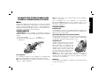 9
9
-
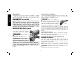 10
10
-
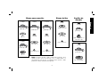 11
11
-
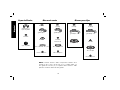 12
12
-
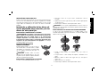 13
13
-
 14
14
-
 15
15
-
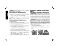 16
16
-
 17
17
-
 18
18
-
 19
19
-
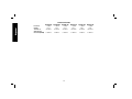 20
20
-
 21
21
-
 22
22
-
 23
23
-
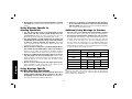 24
24
-
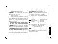 25
25
-
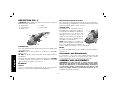 26
26
-
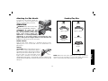 27
27
-
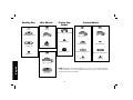 28
28
-
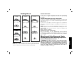 29
29
-
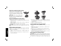 30
30
-
 31
31
-
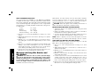 32
32
-
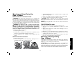 33
33
-
 34
34
-
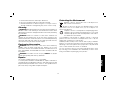 35
35
-
 36
36
-
 37
37
-
 38
38
-
 39
39
-
 40
40


DeWalt D28490 Manual de usuario
- Categoría
- Herramientas eléctricas
- Tipo
- Manual de usuario
En otros idiomas
- English: DeWalt D28490 User manual
Documentos relacionados
-
DeWalt D28474W Manual de usuario
-
DeWalt D28491-AR Manual de usuario
-
-
DeWalt DWE491-B3 Manual de usuario
-
-
DeWalt DWE497 Manual de usuario
-
DeWalt DW880 Manual de usuario
-
-
DeWalt D28493N Manual de usuario
-
Black & Decker D28493N Manual de usuario