
D28490, D28491
Angle Grinder
Esmeriladora Angular
INSTRUCTION MANUAL
MANUAL DE INSTRUCCIONES
INSTRUCTIVO DE OPERACIÓN, CENTROS DE SERVICIO Y PÓLIZA DE
GARANTÍA. ADVERTENCIA: LÉASE ESTE INSTRUCTIVO ANTES DE USAR
EL PRODUCTO.
Questions? See us on the World Wide Web at www.dewalt.com
¿Dudas? Visítenos en Internet: www.dewalt.com


English
1
SAVE THESE INSTRUCTIONS
WARNING! Read and understand all instructions. Failure to
follow all instructions listed below, may result in electric shock, fire
and/or serious personal injury.
General Safety Instructions
WORK AREA
• Keep your work area clean and well lit. Cluttered benches
and dark areas invite accidents.
• Do not operate power tools in explosive atmospheres, such
as in the presence of flammable liquids, gases, or dust.
Power tools create sparks which may ignite the dust or fumes.
• Keep bystanders, children, and visitors away while operating
a power tool. Distractions can cause you to lose control.
ELECTRICAL SAFETY
• Grounded tools must be plugged into an outlet properly
in stalled and grounded in accordance with all codes and
ordinances. Never remove the grounding prong or modify
the plug in any way. Do not use any adapter plugs. Check
with a qualified electrician if you are in doubt as to whether
the outlet is properly grounded. If the tools should electrically
malfunction or break down, grounding provides a low resistance
path to carry electricity away from the user. Applicable only to
Class I (grounded) tools.
• Double insulated tools are equipped with a polarized plug
(one blade is wider than the other.) This plug will fit in a
polarized outlet only one way. If the plug does not fit fully
in the outlet, reverse the plug. If it still does not fit, contact
a qualified electrician to install a polarized outlet. Do not
change the plug in any way. Double insulation
eliminates
the need for the three wire grounded power cord and grounded
power supply system. Applicable only to Class II (double
insulated) tools.
• Avoid body contact with grounded surfaces such as pipes,
radiators, ranges and refrigerators. There is an increased risk
of electric shock if your body is grounded.
• Don’t expose power tools to rain or wet conditions. Water
entering a power tool will increase the risk of electric shock.
• Do not abuse the cord. Never use the cord to carry the
tools or pull the plug from an outlet. Keep cord away from
heat, oil, sharp edges or moving parts. Replace damaged
cords immediately. Damaged cords increase the risk of electric
shock.
• When operating a power tool outside, use an outdoor
extension cord marked “W-A” or “W.” These cords are rated
for outdoor use and reduce the risk of electric shock.
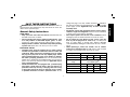
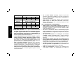
Voltage (Volts)
Total length of cord in meters (m)
120 - 127V 0 - 7 7 - 15 15 - 30 30 - 50
220 - 240V 0 - 15 15 - 30 30 - 60 60 - 100
Rated Ampere
range
Minimal cross-sectional area of the
cord in meters (mm
2
)
0 - 6A 1.0 1.5 1.5 2.5
6 - 10A 1.0 1.5 2.5 4.0
10 - 12A 1.5 1.5 2.5 4.0
12 - 16A 2.5 4.0 Not Recommended

English
2
PERSONAL SAFETY
• Stay alert, watch what you are doing and use common
sense when operating a power tool. Do not use tool while
tired or under the influence of drugs, alcohol, or medication.
A moment of inattention while operating power tools may result
in serious personal injury.
• Dress properly. Do not wear loose clothing or jewelry.
Contain long hair. Keep your hair, clothing, and gloves
away from moving parts. Loose clothes, jewelry, or long hair
can be caught in moving parts. Air vents often cover moving
parts and should also be avoided.
• Avoid accidental starting. Be sure switch is off before
plugging in. Carrying tools with your finger on the switch or
plugging in tools that have the switch on invites accidents.
• Remove adjusting keys or wrenches before turning the tool
on. A wrench or a key that is left attached to a rotating part of
the tool may result in personal injury.
• Do not overreach. Keep proper footing and balance at all
times. Proper footing and balance enables better control of the
tool in unexpected situations.
• Use safety equipment. Always wear eye protection. Dust
mask, non-skid safety shoes, hard hat, or hearing protection
must be used for appropriate conditions.
TOOL USE AND CARE
• Use clamps or other practical way to secure and support
the workpiece to a stable platform. Holding the work by
hand or against your body is unstable and may lead to loss of
control.
• Do not force tool. Use the correct tool for your application.
The correct tool will do the job better and safer at the rate for
which it is designed.
• Do not use tool if switch does not turn it on or off. Any tool
that cannot be controlled with the switch is dangerous and must
be repaired.
• Disconnect the plug from the power source before making
any adjustments, changing accessories, or storing the tool.
Such preventative safety measures reduce the risk of starting
the tool accidentally.
• Store idle tools out of reach of children and other untrained
persons. Tools are dangerous in the hands of untrained users.
• Maintain tools with care. Keep cutting tools sharp and
clean. Properly maintained tools, with sharp cutting edges are
less likely to bind and are easier to control.
• Check for misalignment or binding of moving parts,
breakage of parts, and any other condition that may affect
the tools operation. If damaged, have the tool serviced before
using. Many accidents are caused by poorly maintained tools.
• Use only accessories that are recommended by the
manufacturer for your model. Accessories that may be
suitable for one tool may become hazardous when used on
another tool.
SERVICE
• Tool service must be performed only by qualified repair
personnel. Service or maintenance performed by unqualified
personnel could result in a risk of injury.
• When servicing a tool, use only identical replacement parts.
Follow instructions in the Maintenance section of this manual.
Use of unauthorized parts or failure to follow Maintenance
instructions may create a risk of electric shock or injury.

English
3
minute. If the wire brush has loose wires, they will be detected.
Never start the tool with a person in line with the wheel. This
includes the operator.
• In operation, avoid bouncing the wheel or giving it rough
treatment. If this occurs, stop the tool and inspect the wheel.
• Direct sparks away from operator, bystanders or flammable
materials. Sparks may be produced while using a sander or
grinder. Sparks may cause burns or start fires.
• Always use side handle. Tighten the handle securely. The
side handle should always be used to maintain control of the tool
at all times.
CAUTION: Use extra care when grinding into a corner because a
sudden, sharp movement of the grinder may be experienced when the
wheel contacts a secondary surface.
• Clean out your tool often, especially after heavy use. Dust
and grit containing metal particles often accumulate on interior
surfaces and could create an electric shock hazard.
CAUTION: Wear appropriate personal hearing protection during
use. Under some conditions and duration of use, noise from this
product may contribute to hearing loss.
WARNING: Some dust created by power sanding, sawing,
grinding, drilling, and other construction activities contains chemicals
known to cause cancer, birth defects, or other reproductive harm.
Some examples of these chemicals are:
• lead from lead-based paints,
• crystalline silica from bricks and cement and other masonry
products, and
• arsenic and chromium from chemically-treated lumber (CCA).
Your risk from these exposures varies, depending on how often you
do this type of work. To reduce your exposure to these chemicals:
work in a well ventilated area, and work with approved safety
Additional Specific Safety Instructions
for Grinders
• Always use proper guard with grinding wheel. A guard
protects operator from broken wheel fragments and wheel
contact.
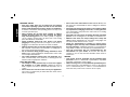
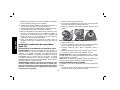
• Accessories must be rated for at least the speed recom-
mended on the tool warning label. Wheels and other
accessories running over rated speed can fly apart and cause
injury. Refer to the table below. Accessory ratings are above
rated no-load tool speeds because actual tool speeds may
vary.
NOTE: The rated no load tool speed is printed on the name plate
and embossed on the gear case.
Rated
n
o (no load) Minimum Accessory
Tool Speed Rating
6500 RPM 6600 RPM
8500 RPM 8500 RPM
• Hold tool by insulated gripping surfaces when performing
an operation where the cutting tool may contact hidden
wiring or its own cord. Contact with a “live” wire will make
exposed metal parts of the tool “live” and shock the operator.
• Before using, inspect recommended accessory for
cracks or flaws. If such a crack or flaw is evident, discard the
accessory. The accessory should also be inspected whenever
you think the tool may have been dropped.
• When starting the tool with a new or replacement wheel, or
a new or replacement wire brush installed, hold the tool in a
well protected area and let it run for one minute. If the wheel
has an undetected crack or flaw, it should burst in less than one

English
4
A
B
D
E
C
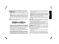
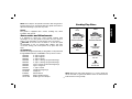
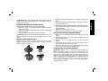
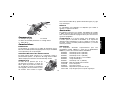
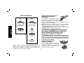
Features
SWITCH
The tool is controlled by a trigger switch (A). A lock-on button (B)
provides increased comfort in extended use applications.
MULTIPLE SIDE HANDLE POSITIONS
The side handle can be properly positioned in two lo ca tions based
on personal preference and application. The side handle must be
used at all times to maintain proper control of the tool.
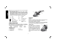
SPINDLE LOCK
C
The spindle lock pin is provided to
prevent the spindle from rotating when
installing or removing wheels. Operate
the spindle lock pin only when the tool is
turned off and unplugged from the power
source. To engage the lock, depress the
spindle lock button (C) and rotate the
spindle until you are unable to rotate it
further.
equipment, such as those dust masks that are specially designed
to filter out microscopic particles.
• Avoid prolonged contact with dust from power sanding,
sawing, grinding, drilling, and other construction activities.
Wear protective clothing and wash exposed areas with
soap and water. Allowing dust to get into your mouth, eyes, or
lay on the skin may promote absorption of harmful chemicals.
• The label on your tool may include the following symbols.
V .......... volts A ............. amperes
Hz ........ hertz W ............ watts
min ......minutes
........... alternating current
....direct current
n
o ........... no load speed
.......Class II Construction …/min ..... revolutions or
........earthing terminal ................ reciprocation per
........safety alert symbol ................ minute
FAMILIARIZATION
Large Angle Grinders and Large Angle Sanders are designed for
heavy material removal in extended use applications. The following
grinders and sanders are described in this manual.
D28490 9" Angle Grinder 6,500 rpm 2200 W
D28491 7" Angle Grinder 8,500 rpm 2200 W
Components
A. Trigger Switch D. Guard
B. Lock On Button E. Side Handle
C. Spindle Lock

English
5
NOTE: Never depress the spindle lock button while the grinder is
running. Never turn on the grinder while the spindle lock button is
depressed. Damage to your tool may result.
MOUNT
The grinder is equipped with a mount, enabling easy wheel
installation and removal.
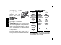
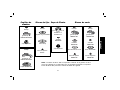
Accessories and Attachments
It is important to choose the correct guards, backing pads
and flanges to use with grinder accessories. See the chart on
pages 5–7 for information on choosing the correct accessories.
CAUTION: Accessories must be rated for at least the speed
recom mended on the tool warning label. Wheels and other
accessories running over rated speed can fly apart and cause
injury.
ATTACHMENTS
Attachments designed specifically for this grinder can be purchased
through D
EWALT dealers and DEWALT Factory Service centers.
D284939 9" Type 27 guard
D284948 9" Type 28 guard
D284937 7" Type 27 guard
D284936 6" Type 11 Flaring cup guard with flange
D284934 4" Type 11 Flaring cup guard with flange
D284933 Type 11 flaring cup wheel backing flange
D284932 Type 1 Flange set
D284931 7" Type 1 Guard
054339-00 Grinding backing flange
22191-00 Clamp nut
61820-01 Wheel Wrench
445928-01 Mount spindle protector
397711-00 Rubber gear case bumper
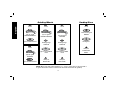
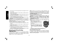
Sanding Flap Discs
mount
mount
type 27 guard
D284937/D284939
type 27 guard
D284937/D284939
hubbed sanding flap
disc
non-hubbed sanding
flap disc
clamp nut
D22191-00
backing flange
54339-00
NOTE: Wheel size must match guard size; i.e., a new 7" wheel may
not be used with a 9" guard. The bottom surface of wheel must be
inside the bend of the guard lip.

English
6
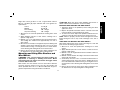
Grinding Wheels
mount
type 27 guard
D284937/D284939
type 27 hubbed wheel
mount
type 28 guard
D284948
type 28 hubbed wheel
mount
type 27 guard
D284937/D284939
backing flange
54339-00
type 27 non-hubbed
wheel
clamp nut
D22191-00
Sanding Discs
mount
rubber backing pad
DW4947
sanding disc
clamp nut
included with
D4947
mount
type 28 guard
D284948
backing flange
54339-00
type 28 non-hubbed
wheel
clamp nut
D22191-00
NOTE: Wheel size must match guard size; i.e., a new 7" wheel may not be used with a
9" guard. The bottom surface of wheel must be inside the bend of the guard lip.

English
7
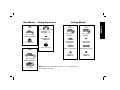
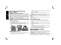
Flaring Cup Stones
Wire Wheels
type 11 flaring cup guard
D284934 — 4"
D284936 — 6"
backing flange
608368-00
flaring cup stone
NOTE: Wheel size must match guard size; i.e., a 7" wheel may not
be used with a 9" guard.
Cutting Wheels
mount
type 1 guard
D284931
backing flange
608370-00
abrasive cutting wheel
clamp nut
608463-00
mount
type 1 guard
D284931
backing flange
608370-00
diamond cutting wheel
clamp nut
608463-00
mount
wire wheel
type 27 guard
D284937/D284939
mount
wire cup brush
type 27 guard
D284937/D284939

English
8
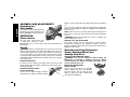
trigger. Lock-on button will remain depressed and tool will remain
on.
To turn the tool off, depress and release trigger. The lock pin button
will pop out, permitting the trigger to disengage and causing the
tool to turn off.
NOTE: Allow the tool to reach full speed before touching tool to
work surface. Lift the tool from the work surface before turning the
tool off.
WARNING: Make sure the wheel has come to a complete stop
be fore setting the tool down.
REMOVAL OF LOCK-ON FEATURE
The lock-on button can be permanently removed without
compromising compliance with regulatory agencies shown on
the tool’s nameplate. Removal of the lock pin must be done by a
D
EWALT service center.
Mounting and Using Depressed
Center Grinding Wheels and
Sanding Flap Discs
MOUNTING AND REMOVING GUARD
WARNING: Turn off and unplug tool before making any
adjustments or removing or installing accessories. Before
reconnecting the tool, depress and release the trigger switch
to ensure that the tool is off.
IMPORTANT INFORMATION
ABOUT GUARDS
Guards must be used with all grinding
wheels, sanding flap discs, wire brushes
and wire wheels. The tool may be used
without a guard only when sanding with
conventional sanding discs.
ASSEMBLY AND ADJUSTMENTS
Attaching the
Side Handle
To install the side handle, thread the
handle into one of the two positions and
tighten securely by turning clockwise.
OPERATION
Power Source
Plug the large angle grinder into
a dedicated elec trical circuit.
Operating this tool on a circuit with other tools will decrease tool
performance.
Switch
WARNING: Before connecting the tool to a power source or after
a power failure, depress and release the trigger switch (A) once
without depressing the lock-on button (B) to ensure that the switch
is in the off position. If the trigger switch is locked on, the tool will
start unexpectedly when power is reconnected to the tool. Hold the
side handle and rear handle firmly to maintain control of tool at start
up and during use.
TRIGGER OPERATION
To turn the tool on, depress the trigger switch (A). The tool will
remain running while the trigger is depressed. Turn the tool off by
releasing the trigger.
TRIGGER OPERATION WITH
A
B
LOCK-ON FEATURE
To turn tool on, depress trigger. Depress
and hold lock-on button (B) while releasing

English
9
90˚
90˚
CAUTION: When using a grinding wheel with a type 27, 28 or 29
guard, be sure that the bottom surface of the grinding wheel is
inside the the guard lip.
MOUNTING AND REMOVING HUBBED WHEELS
Hubbed wheels install directly on the threaded spindle.
1. Thread the wheel on the spindle by hand, seating the wheel
against the mount.
2. Depress the spindle lock button and use a wrench to tighten the
hub of the wheel.
3. Reverse the above procedure to remove the wheel.
CAUTION: Failure to properly seat the wheel against the mount
before turning the tool on may result in damage to the tool or the
wheel.
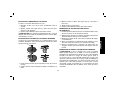
MOUNTING NON-HUBBED WHEELS
Depressed center, Type 27 grinding wheels must be used with
available accessory flanges. See the charts on pages 5–7 of this
manual for more information.
G
E
H
1. Install the metal backing flange (G) on spindle (E) against the
mount.
2. Place wheel against the backing flange, centering the wheel on
the backing flange pilot.
3. While depressing the spindle lock button, thread the clamp nut
(H) on spindle, piloting the raised hub on clamp nut in the center
of grinding wheel.
4. Tighten the clamp nut with a wrench.
5. Reverse the above procedure to remove the wheel.
SURFACE GRINDING WITH GRINDING WHEELS
1. Allow the tool to reach full speed before touching tool to work
surface.
2. Apply minimum pressure to work surface, to allow the tool to
operate at high speed.
3. Maintain a 20˚ to 30˚ angle between the tool and work
surface.
4. Continuously move the tool in a forward and back motion to
avoid creating gouges in the work surface.
5. Remove the tool from work surface before turning tool off. Allow
the tool to stop rotating before setting it down.
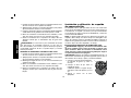
EDGE GRINDING WITH GRINDING WHEELS
CAUTION: Wheels used for cutting and edge grinding may
break if they bend or twist while the tool is being used to do
cut-off work or deep grinding. To reduce the risk of serious injury,
limit the use of these wheels with a standard type 27 guard to
shallow cutting and notching (less than 1/2" in depth). The open
side of the guard must be positioned away from the operator. For
deeper cutting with a type 1 wheel, use a closed, type 1 guard.
Type 1 guards are available at extra cost from your local dealer or
authorized service center.

English
10
1. Allow the tool to reach full speed before touching the tool to the
work surface.
2. Apply minimum pressure to work surface, to allow the tool to
operate at high speed.
3. Protect yourself during edge finishing by directing the open side
of the guard away from you.
4. Move the tool continuously in a forward and back motion to
avoid creating gouges in the work surface.
5. Remove tool from work surface before turning the tool off. Allow
the tool to stop rotating before setting it down.
WARNING: Do not use edge grinding wheels for surface grinding
applications because edge grinding wheels are not designed for
side pressures encountered with surface grinding. Wheel breakage
and injury may result.
SURFACE FINISHING WITH SANDING FLAP DISCS
1. Allow the tool to reach full speed before touching tool to work
surface.
2. Apply minimum pressure to work surface, to allow the tool to
operate at high speed.
3. Maintain a 5˚ to 10˚ angle between the tool and work surface.
4. Continuously move the tool in a forward and back motion to
avoid creating gouges in the work surface.
5. Remove the tool from work surface before turning tool off. Allow
the tool to stop rotating before setting it down.
Mounting and Using Sanding
Backing Pads
Sanding pads and sanding discs must be rated above minimum
accessory speed as shown on tool. Recommended sanding
backing pads and sanding discs are available at extra cost from
D
EWALT service centers and DEWALT dealers.
NOTE: Guard may be removed for sanding applications with
backing pads and sanding discs. Sanding flap discs are considered
grinding wheels by ANSI standards and require the use of a guard.
(See Mounting and Using Depressed Center Grinding Wheels
and Sanding Flap Discs).
MOUNTING SANDING BACKING PADS
WARNING: Turn off and unplug tool before making any
adjustments or removing or installing accessories. Before
reconnecting the tool, depress and release the trigger switch
to ensure that the tool is off.
CAUTION: Proper guard must be re-installed for grinding wheel,
sanding flap disc, wire brush, or wire wheel applications after
sanding applications are complete.
J
I
1. Place or appropriately thread rubber
backing pad (I) down to mount.
2. Place the sanding disc on the rubber
backing pad.
3. While depressing spindle lock, thread
clamp nut (J) on spindle, piloting the
raised hub on the clamp nut into the
center of san ding disc and backing
pad.
4. Tighten the clamp nut with the proper wrench.
5. To remove the wheel, reverse the above procedure.
USING SANDING BACKING PADS
Choose the proper grit sandpaper for your application. Sandpaper
is available in various grits. Coarse grits yield faster material
re moval rates and a rougher finish. Finer grits yield slower material
removal and a smoother finish.

English
11
Begin with coarser grit discs for fast, rough material removal.
Move to a medium grit paper and finish with a fine grit disc for
optimal finish.
Coarse 16 - 30 grit
Medium 36 - 80 grit
Fine Finishing 100 - 120 grit
Very Fine Finishing 150 – 180 grit
1. Allow the tool to reach full speed before touching tool to work
surface.
2. Apply minimum pressure to work surface, allowing tool to
operate at high speed.
3. Maintain a 5˚ to 15˚ angle between the tool and work surface.
The san ding disc should contact approximately one inch of
work surface.
4. Move the tool constantly in a straight line to prevent burning and
swirling of work surface. Allowing the tool to rest on the work
surface without moving, or moving the tool in a circular motion
causes burning and swirling marks on the work surface.
5. Remove the tool from the work surface before turning the tool
off. Allow the tool to stop rotating before setting it down.
Mounting and Using Wire Brushes and
Wire Wheels
WARNING: Turn off and unplug tool before making any
adjustments or removing or installing accessories. Before
reconnecting the tool, depress and release the trigger switch
to ensure that the tool is off.
Wire brushes and wire wheels must be rated above minimum
accessory speed as shown on tool. Use only wire brushes and
wheels provided with a 5/8"–11 or M-14 threaded hub. A type 27
guard is required when using wire brushes and wheels.
CAUTION: Wear work gloves when handling wire brushes or
wheels. Wire brushes and wheels can become sharp.
MOUNTING WIRE BRUSHES AND WIRE WHEELS
1. Thread the wheel on the spindle by hand, seating the wheel
against the mount.
2. Depress the spindle lock button and use a wrench on the hub
of the wire brush or wheel to tighten the wheel.
3. To remove the wheel, depress the spindle lock button and use
a wrench on the hub of the wire brush or wheel to loosen it.
NOTE: Failure to properly seat the wheel hub against the mount
before turning the tool on may result in damage to the tool or
wheel.
USING WIRE CUP BRUSHES AND WIRE WHEELS
Wire wheels and brushes can be used for removing rust, scale and
paint, and for smoothing irregular surfaces.
1. Allow tool to reach full speed before touching tool to work
surface.
2. Apply minimum pressure to work surface, to allow the tool to
operate at high speed.
3. Maintain a 5˚ to 10˚ angle between the tool and work surface for
wire cup brushes.
4. Maintain contact between the edge of the wheel and the work
surface with wire wheels.
5. Continuously move the tool in a forward and back motion to
avoid creating gouges in the work surface. Allowing the tool to
rest on the work surface without moving, or moving the tool in a
circular motion causes burning and swirling marks on the work
surface.
6. Remove the tool from the work surface before turning the tool
off. Allow the tool to stop rotating before setting it down.

English
12
Mounting and Using Flaring Cup
(Type 11) Wheel
MOUNTING FLARING CUP WHEEL GUARD
WARNING: The flaring cup wheel guard is not included with this
tool. Flaring cup wheels require proper flanges and guards. 4"
flaring cup wheel guard D284934 and 6" flaring cup wheel guard
D284936 are available as accessories and include proper flange.
Failure to use the proper flange and guard can result in injury
resulting from wheel break age and wheel contact.
WARNING: Turn off and unplug tool before making any
adjustments or removing or installing accessories. Before
reconnecting the tool, depress and release the trigger switch
to ensure that the tool is off.
1. Install the guard as shown.
2. Guard body should be positioned between the spindle and the
operator to provide maximum operator protection.
3. Securely tighten the two clamping screws supplied with the
guard.
G
K
F
MOUNTING FLARING CUP WHEEL
1. Remove the mount (F).
2. Install the flaring cup wheel backing flange, aligning the flats on
spindle (K) with the flats on backing flange (G).
3. Thread the flaring cup wheel on spindle by hand, seating wheel
against backing flange.
4. Depress the spindle lock button and tighten the wheel by
hand.
5. To remove the wheel, reverse the above procedure.
CAUTION: Failure to properly seat the wheel against backing
flange before turning the tool on may result in damage to the tool or
the wheel.
NOTE: Adjust the guard skirt so that only 1/8" of the wheel is
exposed below the skirt.
USING A FLARING CUP WHEEL
Flaring cup wheels are designed for heavy material removal.
1. Allow the tool to reach full speed before touching tool to work
surface.
2. Apply minimum pressure to work surface, allowing the tool to
oper ate at high speed.
3. Maintain a 5˚ to 10
˚
angle between the tool and the work
surface.
4. Continuously move the tool in a forward and back motion to
avoid creating gouges in the work surface.
5. Remove the tool from work surface before turning tool off. Allow
the tool to stop rotating before setting it down.
Mounting and Using Cutting
(Type 1) Wheels
Cutting wheels include diamond wheels and abrasive discs.
Abrasive cutting wheels for metal and concrete use are available.
Diamond blades for concrete cutting can also be used.
WARNING: A closed, cutting wheel guard is not included with
this tool. Cutting wheels require proper flanges and guards. A
7" cutting guard, D284931, is available as an accessory and

English
13
includes proper, matching flanges. Failure to use proper flange
and guard can result in injury resulting from wheel breakage and
wheel contact.
MOUNTING CLOSED (TYPE 1) GUARD
WARNING: Turn off and unplug tool before making any
adjustments or removing or installing accessories. Before
reconnecting the tool, depress and release the trigger switch
to ensure that the tool is off.
1. Align the lugs with slots on the gear case cover. Position the
guard facing backward, as shown.
2. Push the guard down until the guard lug engages and rotates
freely in the groove on the gear case hub.
3. Rotate guard into desired working position. The guard body
should be positioned between the spindle and the operator to
provide maximum operator protection.
4. Secure the guard on the gear case cover. You should be
unable to rotate the guard by hand when the latch is in closed
position. Do not operate grinder with a loose guard or clamp
lever in open position.
NOTE: The guard is pre-adjusted to the dia met er of the gear case
hub at the factory. If, after a period of time, the guard be comes
loose, tighten the adjusting screw.
MOUNTING CUTTING WHEELS
1. Remove mount.
2. Install wheel backing flange, aligning flats on spindle with flats
on backing flange.
3. Place the wheel on the backing flange, centering the wheel on
the backing flange pilot.
4. Install the clamp nut, ensuring that the wheel remains centered
on the backing flange.
5. Depress the spindle lock button and tighten clamp nut with
wrench.
6. Reverse the above procedure to remove the wheel.
USING CUTTING WHEELS
1. Allow tool to reach full speed before touching tool to work
surface.
2. Apply minimum pressure to work surface, allowing tool to
operate at high speed.
3. Once you begin a cut, maintain the angle of the cutting wheel
to the work surface. This will keep you from bending the wheel
which could result in wheel breakage and injury.
4. Remove the tool from work surface before turning tool off. Allow
the tool to stop rotating before setting it down.
MAINTENANCE
WARNING: Turn off and unplug tool before making any
adjustments or removing or installing accessories. Before
reconnecting the tool, depress and release the trigger switch
to ensure that the tool is off.
Cleaning
WARNING: Blow dirt and dust out of the main housing with dry
air as often as dirt is seen collecting in and around the air vents.
Wear approved eye protection and approved dust mask when
performing this procedure.
WARNING: Never use solvents or other harsh chemicals for
cleaning the non-metallic parts of the tool. These chemicals may
weaken the materials used in these parts. Use a cloth dampened
only with water and mild soap. Never let any liquid get inside the
tool; never immerse any part of the tool into a liquid.

English
14
Lubrication
DEWALT tools are properly lubricated at the factory and are ready
for use.
Repairs
To assure product SAFETY and RELIABILITY, repairs, maintenance
and adjustment should be performed by authorized service
centers or other qualified service personnel. Always use identical
replacement parts.
Motor Brushes
When brushes become worn, the tool will automatically stop,
preventing damage to the motor. Brush replacement should be
performed by D
EWALT authorized service centers or other qualified
service personnel. Qualified service personnel should follow the
procedures below when replacing motor brushes.
Turn off and unplug tool before making any adjustments or
removing or installing accessories. Before reconnecting the
tool, depress and release the trigger switch to ensure that the
tool is off.
1. Remove the brush doors located on the sides of motor
housing.
2. To remove the brush, hold the female terminal, which is
attached to the brush lead wire, and disconnect the female
terminal from the male terminal.
3. Pull the brush straight up out of the brush holder.
4. Replace brushes, in pairs, with original D
EWALT brushes
available from D
EWALT authorized service centers.
5. Ensure that the brushes slide freely in brush box.
6. Reconnect the brush lead wire to brush box terminal.
7. Re-install the brush doors before using the tool. Torque screws
to 10 in-lbs, maximum. Overtightening may cause screws to
strip.
Purchasing Accessories
WARNING: Since accessories, other than those offered by
D
EWALT, have not been tested with this product, use of such
accessories with this tool could be hazardous. To reduce the risk of
injury, only D
EWALT, recommended accessories should be used
with this product.
Recommended accessories for use with your tool are available at
extra cost from you local dealer or authorized service center.

Español
15
Medidas generales de seguridad
¡ADVERTENCIA! Lea y comprenda todas las instrucciones.
El no cumplir con todas las advertencias a continuación podría
resultar en el riesgo de un choque eléctrico, incendio o de
lesiones graves.
CONSERVE ESTAS INSTRUCCIONES
Instrucciones generales de seguridad
ÁREA DE TRABAJO
• Conserve el área de trabajo limpia y bien iluminada. Las
bancas desordenadas y las zonas oscuras podrían ocasionar
ac ciden tes.
• No opere herramientas eléctricas en atmósferas
explosivas, como en presencia de líquidos, gases o polvos
inflamables. Las herramientas eléctricas producen chispas que
pueden incendiar el polvo o los vapores.
• Mantenga a los niños, visitantes y demás personas
alejadas mientras opera una herramienta eléctrica. Las
distracciones pueden hacer que pierda el control.
SEGURIDAD ELÉCTRICA
• Las herramientas de conexión a tierra deben conectarse a
una toma de corriente instalada puesta a tierra debidamente
en conformidad con todos los códigos y regulaciones
locales. Nunca retire la clavija de conexión a tierra, no
modifique el enchufe ni utilice adaptadores. Consulte
con un electricista calificado si tiene dudas acerca de la
conexión a tierra apro piada de su toma de corriente. En el
caso que la herramienta tuviese una falla eléctrica, la puesta
a tierra proporciona una vía de baja resistencia para alejar la
electricidad del usuario. Aplicable únicamente a herramientas
clase I (puestas a tierra).
• Las herramientas con doble aislamiento están equipadas
con una clavija polarizada (con una pata más ancha que
la otra.) Esta clavija se acoplará únicamente en una toma de
corriente polarizada en un sentido. Si la clavija no se acopla
al contacto, inviértala. Si aún así no se ajusta, comuníquese
con un electricista calificado para que le instalen una toma de
corriente polarizada apropiada. El doble aislamiento elimina la
necesidad de cables con tres hilos y sistemas de alimentación
de conexión a tierra. Aplicable a herramientas clase II (con
doble aislamiento).
• Evite el contacto corporal con las superficies puestas
a tierra incluyendo las tuberías radiadores, hornos y
refrigeradores. Existe un gran riesgo de choque eléctrico si su
cuerpo hace tierra.
• No exponga las herramientas eléctricas a la lluvia o a
condiciones de mucha humedad. El agua que penetra
las herra mientas eléctricas aumenta el riesgo de un choque
eléctrico.
• No maltrate el cable. Nunca sujete el cable para transportar
la herramienta ni para desconectarla de la toma de corriente.
Mantenga el cable alejado del calor, aceite, bordes afilados
o del calor. Cambie inmediatamente los cables dañados. Los
cables dañados aumentan el riesgo de choque eléctrico.
• Cuando opere una herramienta eléctrica a la intemperie,
utili ce una extensión con el sello “W-A” o “W”. Estas
extensiones están clasificadas para uso a la intemperie y para
reducir el riesgo de choques eléctricos.

Español
16
Ténsion (Volts) Longitud del cable en metros (m)
120 - 127V 0 - 7 7 - 15 15 - 30 30 - 50
220 - 240V 0 - 15 15 - 30 30 - 60 60 - 100
Corriente nominal
(Ampéres)
Sección nominal mínima del cable en
milímetros cuadrados (mm
2
)
0 - 6A 1.0 1.5 1.5 2.5
6 - 10A 1.0 1.5 2.5 4.0
10 - 12A 1.5 1.5 2.5 4.0
12 - 16A 2.5 4.0 No recomendado
SEGURIDAD PERSONAL
• Esté alerta, concéntrese en lo que está haciendo. Recurra
al sentido común cuando opere una herramienta eléctrica.
No opere ninguna herramienta si se encuentra fatigado o
bajo la influencia de drogas, alcohol o medicamentos. Un
momento de desatención mientras se operan herramientas
eléctricas puede ocasionar lesiones graves.
• Vístase apropiadamente. No use ropa holgada ni joyería.
Cubra o recójase el cabello. Mantenga el cabello, la ropa y
los guantes alejados de las partes en movimiento. La ropa
floja, joyería o el cabello largo podría quedar atrapado en las
partes móviles. Los escapes de aire algunas veces cubren las
partes en movimiento y también deben ser evitadas.
• Evite el encendido accidental. Asegúrese que el interruptor
esté apagado antes de conectar. El sujetar una hera mienta con
el dedo en el interruptor o conectarla sin fijarse si el interruptor
está en posición de encendido podría ocasionar un accidente.
• Retire las llaves de ajuste antes de encender la herramienta.
Una llave que se deja en una pieza giratoria puede ocasionar
lesiones personales.
• No se sobre extienda. Mantenga siempre los pies bien
apoyados, al igual que el equilibrio. La posición correcta de los
pies y el equilibrio permiten controlar mejor la herramienta en
situaciones inesperadas.
• Utilice equipo de seguridad. Siempre utilice protección
para los ojos. Se deben utilizar mascarillas contra polvo,
zapatos antideslizantes, casco o protectores para los oídos
conforme sea necesario.
USO Y CUIDADOS DE LA HERRAMIENTA
• Utilice prensas u otros medios prácticos para asegurar y
apoyar la pieza de trabajo en una plataforma estable. Sujetar
las piezas con la mano o contra su cuerpo es inestable y puede
originar la pérdida de control.
• No fuerce la herramienta. Utilice la herramienta apropiada
según la aplicación. La herramienta apropiada hará el trabajo
mejor y de manera más segura bajo las especificaciones para
las que se diseñó.
• No utilice la herramienta si el interruptor no enciende
ni apaga. Cualquier herramienta que no pueda controlarse
por medio de interruptores antideslizantes peligrosa y debe
repararse.
• Desconecte el enchufe de la toma de corriente antes de
hacer cualquier ajuste, cambio de accesorios o de guardar la
herra mienta. Tales medidas preventivas de seguridad reducirán
el riesgo de que la herramienta se encienda accidentalmente.
• Guarde las herramientas fuera del alcance de los niños y
de otras personas no capacitadas. Las herramientas son
peligrosas en manos de personas no capacitadas.
• Cuide sus herramientas. Conserve las herramientas de
corte afiladas y limpias. Las herramientas que reciben un

Español
17
mantenimiento adecuado, con piezas de corte afiladas,
difícilmente se atascan y son más fáciles de controlar.
• Verifique la alineación de las piezas móviles, busque
fracturas en las piezas demás condiciones que puedan
afectar la oper a ci ón de las herramientas. Si está dañada,
lleve su herramienta a servicio antes de usarla de nuevo.
Muchos accidentes se deben a herramientas con mantenimiento
pobre.
• Solamente use accesorios que el fabricante recomiende
para su modelo de herramienta. Los accesorios que han
sido diseñados para utilizarse con cierto tipo de herramientas,
pueden ocasionar peligro al emplearse con otras.
SERVICIO
• El servicio a las herramientas lo debe efectuar únicamente
personal calificado. El servicio o mantenimiento realizado por
personal no calificado puede ocasionar el riesgo de lesiones
persona les.
• Cuando efectúe servicio a una herramienta, utilice
únicamente refacciones idénticas. Siga las instrucciones de
la sección de mantenimiento de este manual. El uso de piezas
no auto rizadas o no seguir las instrucciones de mantenimiento
puede ocasionar riesgo de choque eléctrico o lesiones.
Instrucciones adicionales de seguridad
específicas para esmeriladoras
• Siempre utilice la guarda apropiada con el disco de
esmeril. Las guardas protegen al usuario contra los fragmentos
de los discos rotos y del contacto con los discos.
• Los accesorios deberán estar clasificados por lo menos
la velocidad recomendada en la etiqueta de advertencia
de la herramienta. Las discos y demás accesorios que
funcionen a una velocidad mayor a la clasificada, pueden
romperse y causar lesiones. Consulte la tabla a continuación. La
clasificación de los accesorios está sobre la clasificación de
velocidad sin carga de la herramienta, ya que las velocidades
reales pueden variar.
NOTA: la velocidad sin carga de la herramienta está impresa en la
placa de identificación y está grabada en la caja de engranajes.
• Sujete la herramienta por las superficies aislantes cuando
efectúe una operación en la que la herramienta de corte
pueda hacer contacto con cableado oculto o con su
propio cable. El contacto con un cable “vivo” hará que las
partes expuestas de la herramienta “vivan” y descarguen en el
usuario.
• Antes de usar los accesorios recomendados, revíselos
siempre en busca de quebraduras o defectos. Descártelos
si tienen un desperfecto de esta clase. Deberá revisar, de la
misma mane ra, los accesorios cuando sospeche que la unidad
se ha dejado caer.
• Al accionar la herramienta (con un disco o con un cepillo
nuevo de reemplazo), sujétela bien dentro de una zona
protegida adecuadamente y déjela funcionar durante un
minuto. Si el disco estuviese quebrado o dañado, se rompería
en pedazos en menos de un minuto. El usuario jamás deberá
accionar la herra mienta con el disco dirigido hacia otra persona
ni hacia si mismo.
Velocidad sin carga Clasificación mínima
de la herramienta del accessorio
6500 RPM 6600 RPM
8500 RPM 8500 RPM

Español
18
• Evite que el disco opere a saltos o se maltrate mientras
funciona. Si sucediera así, apague y desconecte la herra-
mienta y revise el disco.
• Dirija las chispas lejos del operador, demás personas o
materiales inflamables. Se pueden producir chispas al utilizar
una lijadora o esmeriladora. Las chispas pueden ocasionar
quemaduras u ocasionar incendios.
• Utilice siempre el mango lateral. Apriete el mango con
firmeza. El mango lateral debe utilizarse siempre para mantener
el control de la unidad en todo momento.
PRECAUCIÓN: Tenga mucho cuidado al esmerilar cerca de una
esquina, ya que puede experimentarse un movimiento repentino,
violento de la esmeriladora al hacer contacto el disco con una
segunda superficie.
• Limpie la herramienta periódicamente. El polvo y el esmeril
contienen partículas metálicas que se acumulan con frecuencia
en las superficies interiores y pueden ocasionar riesgos de
choque eléctrico.
PRECAUCIÓN: utilice la protección auditiva apropiada durante
el uso de la herramienta. Bajo ciertas condiciones y duración de
uso, el ruido producido por este producto puede contribuir a la
pérdida auditiva.
ADVERTENCIA: Parte del polvo originado al lijar, cortar, esme-
rilar, taladrar y otras actividades constructivas contiene químicos
que se sabe causan cáncer, defectos congénitos y otros daños
reproductivos. Algunos ejemplos de estos químicos son:
• plomo de pinturas con base de plomo.
• sílice cristalino de ladrillos, cemento y otros productos de
albañi lería, y
• arsénico y cromo de madera tratada químicamente (CCA).
El riesgo a estas exposiciones varía, dependiendo de la frecuencia
con la que efectúe este tipo de trabajos. Para reducir su exposición
a estos químicos, trabaje en un área bien ventilada, y trabaje con
equipo de seguridad aprobado, como aquéllas máscaras que están
diseñadas especialmente para filtrar partículas microscópicas.
• Evite el contacto prolongado con el polvo originado por lijar,
cortar, esmerilar, taladrar, y otras actividades constructivas.
Vista ropas protectoras y lave las zonas expuestas con
jabón y agua. Permitir que el polvo se introduzca en su boca,
ojos, o quede sobre su piel promueve la absorción de químicos
nocivos.
• La etiqueta de su herramienta puede incluir los siguientes
símbolos.
V ............ volts A .........amperios
Hz .......... hertz W ........watts
.../min .... minutos
.......corriente alterna
....... corriente directa
n
o .......velocidad sin carga
......... construcción clase II /min .....revoluciones por
.......... terminales de ............minuto
.............. conexión a tierra .......símbolo de advertencia
CONOCIMIENTO DEL PRODUCTO
Las esmeriladoras y lijadoras angulares grandes están diseña-
das para la remoción pesada de material en aplicaciones de uso
prolongado. Las siguientes esmeriladoras y lijadoras aparecen
descritas en este manual.
D28490 Esmeriladora angular de 9" (230 mm) 6,500 rpm 2200 W
D28491 Esmeriladora angular de 7" (180 mm) 8,500 rpm 2200 W

Español
19
A
B
D
E
C
Componentes
A. Interruptor de gatillo D. Guarda
B. Botón de encendido permanente E. Mango lateral
C. Traba del eje
Características
INTERRUPTOR
La herramienta se controla con un gatillo de interrupción (A). El
botón de encendido permanente (B) proporciona mayor comodidad
en las aplicaciones de uso prolongado.
POSICIONES MÚLTIPLES DEL MANGO LATERAL
El mango lateral puede colocarse en 2 posiciones según la
preferen cia del operario y la aplicación. El mango lateral se debe
utilizar siempre para mantener la herramienta bajo control.
TRABA DEL EJE
C
La traba del eje previene que el eje
gire mientras se instalan o se retiran los
discos. Ajuste el pasador de la traba del
eje únicamente cuando la herra mienta
esté apagada y desconectada de la toma
de corriente. Para accionar el seguro.
Para accionar la traba del eje, oprima el botón del seguro (C) y gire
el eje hasta topar.
MONTAJE
La esmeriladora está equipada con dispositivo que facilita el
montaje y la remoción de discos.
Accesorios
Es importante seleccionar las guardas, almohadillas de respaldo
y bridas correctas para usarse con los accesorios de la esmerila-
dora. Consulte las tablas de las páginas 20–22 para seleccionar los
accesorios apropiados.
PRECAUCIÓN: los accesorios deben estar clasificados por
lo menos para la velocidad recomendada en la etiqueta de
advertencia de la herramienta. Los discos y demás accesorios que
funcionen a mayor velocidad pueden desprenderse y ocasionar
lesiones personales.
DISPOSITIVOS
Los dispositivos diseñados específicamente para esta
esmeriladora pueden adquirirse a través de los distribuidores
D
EWALT y centros de servicio de fábrica de DEWALT.
D284939 Guarda tipo 27 de 9" (230 mm)
D284948 Guarda tipo 28 de 9" (230 mm)
D284937 Guarda tipo 27 de 7" (180 mm)
D284933 Piedra de copa tipo 11 con arandela
D284932 Juego de brida tipo 1
D284931 Guarda tipo 1 de 7" (180 mm)
054339-00 Brida de respaldo para esmerilar
22191-00 Tuerca de fijación
61820-01 Llave para el disco
445928-01 Dispositivo de protección del eje
397711-00 Tope de goma para la caja de engranajes

Español
20
ENSAMBLAJE Y AJUSTES
Instalación del
mango lateral
Para instalar el mango lateral,
enrósquelo en una de las dos
posiciones y apriételo con firmeza
girándolo hacia la derecha.
OPERACIÓN
Alimentación de
corriente
Conecte la esmeriladora angular grande a un circuito eléctrico
dedi cado. El operar esta herramienta en un circuito con otras herra -
mientas, resultará en un rendimiento menor.
Interruptor
PRECAUCIÓN: Antes de conectar la herramienta a una toma
de corriente o después de una falla en la alimentación, oprima y
suelte el interruptor de gatillo (A) una vez sin oprimir el botón de
encendido permanente (B) para asegurarse que el interruptor esté
apagado. Si el interruptor de gatillo tiene ajustado el seguro de
operación continua, la herramienta se encenderá inadvertidamente
al conectar de nuevo la herramienta. Sujete con firmeza el mango
lateral y el mango trasero para mejor control de la herra mienta al
encenderla y al operarla.
OPERACIÓN DEL GATILLO
Para encender la herramienta, oprima el interruptor de gatillo (A).
La herramienta permanecerá encendida mientras oprima el gatillo.
Suelte el gatillo para apagar la herra mienta.
Discos para esmerilar
montaje
guarda tipo 27
D284937/D284939
disco
tipo 27
montaje
guarda tipo 28
D284948
disco
tipo 28
montaje
guarda tipo 27
D284937/D284939
arandela
D54339-00
disco tipo 27
tuerca de fijación
D22191-00
montaje
guarda tipo 28
D284948
arandela
D54339-00
disco tipo 28
tuerca de fijación
D22191-00
NOTA: el tamaño del disco debe corresponder al tamaño de la
guarda; un disco nuevo de 7 pulgadas no se debe utilizar con
una guarda de 9 pulgadas. La superficie inferior del disco debe
permanecer adentro del borde de la guarda.

Español
21
Español
Discos de lijar
montaje
respaldo de goma D4947
disco de lija
tuerca de fijación
D4947
Copa de Piedra
Cepillos de
alambre
montaje
guarda tipo 27
D284937/D284939
montaje
guarda tipo 27
D284937/D284939
guarda tipo 11 copa de
piedra
D284934 de 4"
D284936 de 6"
arandela
608368-00
copa de piedra
Discos de corte
montaje
guarda tipo 1
D608561-00
arandela
608370-00
disco diamantado
montaje
guarda tipo 1
D608561-00
arandela
608370-00
disco abrasivo de corte
tuerca de fijación
608463-00
tuerca de fijación
608463-00
NOTA: el tamaño del disco debe corresponder al tamaño de la guarda; un disco
nuevo de 7 pulgadas no se debe utilizar con una guarda de 9 pulgadas. La superficie
inferior del disco debe permanecer adentro del borde de la guarda.
copa de piedra
cepillos de alambre

Español
22
OPERACIÓN DEL GATILLO CON EL
A
B
DISPOSITIVO DE ENCENDIDO
PERMANENTE
Para encender la herramienta, oprima el
gatillo. Oprima y sujete el botón de encendido
permanente (B) mientras suelta el gatillo. El
botón de encendido permanente permanecerá oprimido y la herra-
mienta permanecerá encendida.
NOTA: Permita que la herramienta alcance la velocidad máxima.
Antes de hacer contacto con la superficie de trabajo. Levante la
herramienta de la superficie de trabajo antes de apagarla.
PRECAUCIÓN: asegúrese de que el disco se haya detenido
completamente antes de poner la herramienta.
Instalación y utilización de los discos
de centro deprimido para esmerilar y
de los discos de aleta para lijar
INSTALACIÓN Y REMOCIÓN DE LA GUARDA
ADVERTENCIA: Apague y desconecte la herramienta antes
de hacer cualquier ajuste o antes de instalar o remover cual-
quier accesorio. Antes de conectar la herra mienta nuevamente,
presione y suelte el interruptor de gatillo para asegurarse que
la herramienta esté apagada.
INFORMACIÓN IMPORTANTE
SOBRE LAS GUARDAS
Se debe utilizar guardas con todos los
discos de esmerilar, discos de lijar, ruedas
y cepillos de alambre. La herramienta se
puede utilizar sin una guarda únicamente
para lijar con discos corrientes.
Discos para lijar
montaje
montaje
guarda tipo 27
D284937/D284939
guarda tipo 27
D284937/D284939
disco para lijar
disco de lijar
tuerca de fijación
D22191-00
arandela
D54339-00
NOTA: el tamaño del disco debe corresponder al tamaño de la
guarda; un disco nuevo de 7 pulgadas no se debe utilizar con
una guarda de 9 pulgadas. La superficie inferior del disco debe
permanecer adentro del borde de la guarda.

Español
23
INSTALACIÓN Y REMOCIÓN DE LOS DISCOS
Los discos se instalan directamente en el eje.
1. Enrosque el disco en el eje a mano, asentándolo contra el
montaje.
2. Oprima el botón del seguro del eje y utilice una llave para
apretar el cubo del disco.
3. Invierta el procedimiento anterior para retirar el disco.
PRECAUCIÓN: El no asentar apropiadamente el disco contra el
montaje antes de encender la herramienta podria ocasionar daño
a herramienta o al disco.
INSTALACIÓN DE LOS DISCOS CON CENTRO DEPRIMIDO
Los discos de centro deprimido tipo 27, se deben utilizar con las
arandelas disponibles. Para más información consulte las tablas
que aparecen de este manual.
G
E
H
1. Instale el flanje metálico (G) de respaldo en el eje (E) contra el
montaje.
2. Coloque el disco contra el flanje de respaldo, centrándolo en el
flanje.
3. Mientras oprime el botón del seguro del eje, enrosque la
tuerca (H).
4. Apriete la tuerca con una llave.
5. Invierta el procedimiento anterior para retirar el disco.
ESMERILADO DE SUPERFICIES CON DISCOS
DE ESMERILAR
1. Permita que la herramienta alcance la velocidad máxima antes
de hacer contacto con la superficie de trabajo.
2. Aplique presión mínima a la superficie de trabajo, para permitir
que la herramienta funcione a alta velocidad.
3. Mantenga un ángulo de 20° a 30° entre la superficie de trabajo
y la herramienta.
4. Mueva la herramienta contínuamente hacia adelante y hacia
atrás para evitar crear marcas en la superficie de trabajo.
5. Retire la herramienta de la superficie de trabajo antes de
apagarla. Permita que la herramienta deje de girar antes de
ponerla.
ESMERILADO DE BORDES CON DISCOS DE ESMERILAR
PRECAUCIÓN: los discos utilizados para cortar y esmerilar
bordes pueden romperse si se doblan o se tuercen mientras la
herra mienta se utiliza para hacer trabajos de corte o de esmerilado
profundo. Para reducir los riesgos de lesiones graves, limite el
uso de estos discos con una guarda estándar tipo 27 para corte
superficial y ranurado (menos de 13 mm [1/2"] de profundidad). El
lado abierto de la guarda debe colocarse hacia el lado opuesto del
operador. Para cortes más profundos con un disco tipo 1, utilice
una guarda cerrada. Las guardas tipo 1 se encuentran a la venta
a través del distribuidor de su localidad o en un centro de servicio
autorizado.

Español
24
Instalación y utilización de respaldo
de goma para lijar
Las respaldo y discos para lijar deben de tener una clasificación
mayor que la velocidad mínima para accesorios según aparece en
la herramienta. el respaldo y los discos para lijar recomendados
se encuentran a la venta a través de lo distribuidores y centros de
servicio autorizado D
EWALT.
NOTA: la guarda puede retirarse para aplicaciones de lijado con
respaldo y discos de lija. Los discos de lijar son catalogados como
discos de esmerilar según los estándares de ANSI y requieren el
empleo de una guarda. (Consulte la sección sobre la instalación y
uso de los discos de centro deprimido y los de lija.)
INSTALACIÓN DE RESPALDO DE GOMA PARA LIJAR
ADVERTENCIA: Apague y desconecte la herramienta antes
de hacer cualquier ajuste o antes de instalar o remover cual-
quier accesorio. Antes de conectar la herra mienta nueva-
mente, presione y suelte el interruptor de gatillo para asegura-
rse que la herramienta esté apagada.
PRECAUCIÓN: Después de utilizar la herramienta para lijar, se
debe instalar nuevamente las guardas apropiadas para los discos
de esmerilar, discos de lijar, cepillos y ruedas de alambre.
1. Coloque o enrosque apropiadamente
J
I
el respaldo de goma (I) sobre el
montaje.
2. Coloque el disco de lija sobre el
respaldo de goma.
3. Mientras oprime el seguro del eje,
enrosque la tu erca de fijación (J) en el
eje.
4. Apriete la tuerca con la llave
apropiada.
1. Permita que la herramienta alcance la velocidad máxima antes
de hacer contacto con la superficie de trabajo.
2. Aplique presión mínima a la superficie de trabajo, para permitir
que la herramienta funcione a alta velocidad.
3. Protéjase usted mismo durante el acabado de bordes dirigiendo
el lado abierto de la guarda hacia el lado opuesto a usted.
4. Mueva la herramienta contínuamente hacia adelanta y hacia
atrás para evitar crear marcas en la superficie de trabajo.
5. Retire la herramienta de la superficie de trabajo antes de
apagarla. Permita que la herra mienta deje de girar antes
ponerla.
ADVERTENCIA: no utilice discos para esmerilado de bordes
para aplicaciones de esmerilado superficial, ya que éstos no
han sido diseñados para resistir la presión lateral que produce
el esmerilado superficial. El disco se podría romper y ocasionar
lesiones personales.
ACABADO DE SUPERFICIES CON DISCO PARA LIJAR
1. Permita que la herramienta alcance la velocidad máxima antes
de hacer contacto con la superficie de trabajo.
2. Aplique presión mínima a la superficie de trabajo, para permitir
que la herramienta funcione a alta velocidad.
3. Mantenga un ángulo de entre 5° y 10° entre la herramienta y la
superficie de trabajo.
4. Mueva la herramienta continuamente hacia adelanta y hacia
atrás para evitar crear marcas en la superficie de trabajo.
5. Retire la herramienta de la superficie de trabajo antes de
apagarla. Permita que la herramienta deje de girar antes de
bajarla.

Español
25
5. Para retirar el disco, invierta el procedimiento anterior.
UTILIZACIÓN DE RESPALDO DE GOMA PARA LIJAR
Seleccione el papel de lija con el grano apropiado para su
aplicación. El papel de lija se vende en diferentes granos. Los
granos gruesos permiten remover el material con mayor rapidez
dejando un acabado áspero. Los granos más finos remueven
menos material y permiten un acabado más fino. Cambie a un
grano mediano y termine con grano fino para abtener el acabado
óptimo.
Comience con granos más gruesos para la remoción rápida de
material áspero.
Grueso grano 16 - 30
Mediano grano 36 - 80
Acabado fino grano 100 - 120
Acabado muy fino grano 150 - 180
1. Permita que la herramienta alcance la velocidad máxima antes
de hacer contacto con la superficie de trabajo.
2. Aplique presión mínima a la superficie de trabajo, para permitir
que la herramienta funcione a alta velocidad.
3. Mantenga un ángulo entre 5° y 15° entre la herramienta y la
superficie de trabajo. El disco de lija debe hacer contacto con
aproxi madamente una pulgada (25 mm) de la superficie de
trabajo.
4. Mueva la herramienta continuamente en línea recta para
evitar que la superficie de trabajo se queme o se marque.
5. Retire la herramienta de la superficie de trabajo antes de
apagarla. Permita que la herramienta deje de girar antes de
bajarla.
Instalación y utilización de respaldo de
goma para lijar
ADVERTENCIA: Apague y desconecte la herramienta antes
de hacer cualquier ajuste o antes de instalar o remover cual-
quier accesorio. Antes de conectar la herra mienta nueva-
mente, presione y suelte el interruptor de gatillo para asegura-
rse que la herramienta esté apagada.
Las copas y las ruedas de alambre deben tener una clasificación
mayor que la velocidad mínima según lo señala la herramienta.
Utilice únicamente copas y ruedas de alambre de cubo con rosca
de 5/8" a 11". Se requiere una guarda tipo 27 cuando se utilizan
copas o ruedas de alambre.
PRECAUCIÓN: Use guantes para manejar las copas y las
ruedas de alambre ya que éstas son puntiagudas.
INSTALACIÓN DE COPAS Y RUEDAS DE ALAMBRE
1. Enrosque la rueda a mano sobre el eje asentándola contra el
montaje.
2. Oprima el botón de seguro del eje y utilice una llave para
apretar el cubo de la copa o de la rueda de alambre.
3. Para retirar la rueda, oprima el botón del seguro del eje y
utilice una llave para aflojar el cubo de la copa o de la rueda
de alambre.
NOTA: El no asentar apropiadamente el cubo de la rueda contra
el montaje podría dañar la herramienta o la rueda.
UTILIZACIÓN DE COPAS DE ALAMBRE Y RUEDAS DE
ALAMBRE TRENZADO
Los cepillos de alambre pueden utilizarse para remover óxido,
escamas y pintura, y para alisar superficies irregulares.
1. Permita que la herramienta alcance la velocidad máxima antes
de hacer contacto con la superficie de trabajo.

Español
26
1. Instale la guarda según la ilustración.
2. El cuerpo de la guarda debe colocarse entre el eje el operador
para proporcionarle a éste máxima protección.
3. Apriete con firmeza los dos tornillos de fijación incluidos con la
guarda.
G
K
F
INSTALACIÓN DE LA COPA DE PIEDRAS
1. Retire el montaje (F).
2. Instale el respaldo de la piedra de copa, haciendo coincidir los
planos en del eje (K) con los planos de respaldo (G).
3. Enrosque piedra de copa a mano, asentándolo contra el
respaldo.
4. Oprima el botón del seguro del eje y apriete el disco a mano.
5. Para retirar la copa, invierta el procedimiento anterior.
PRECAUCIÓN: No asentar apropiadamente el disco contra el
respaldo antes de encender la herramienta podriá ocasio nar daño
a la herra mienta o a la piedra.
NOTA: Ajuste el faldón de la guarda de manera que únicamente 3
mm (1/8") del disco quede expuesto por debajo del faldón.
UTILIZACIÓN DE UNA COPA DE RIEDRA
Las piedras de copa están diseña das para remoción agresiva de
material.
1. Permita que la herramienta alcance la velocidad máxima antes
de hacer contacto con la superficie de trabajo.
2. Aplique presión mínima a la superficie de trabajo, para permitir
que la herramienta funcione a alta velocidad.
3. Cuando utilice copas de alambre, mantenga un ángulo de 5° y
10° entre la herramienta y la superficie de trabajo.
4. Cuando utilice ruedas de alambre trenzado, mantenga contacto
entre el borde de la rueda y la superficie de trabajo.
5. Mueva la herramienta contínuamente hacia adelanta y hacia
atrás para evitar crear marcas en la superficie de trabajo. El
permitir que la herramienta descanse sobre la superficie de
trabajo sin moverla, y los movimientos circulares producen
quemaduras sobre la superficie de trabajo.
6. Retire la herramienta de la superficie de trabajo antes de
apagarla. Permita que la herramienta deje de girar antes de
ponerla.
Instalación y utilización de copa piedras
(tipo 11)
INSTALACIÓN DE LA GUARDA DE LAS PIEDRAS DE COPA
ADVERTENCIA: la guarda para piedras de viene incluída con
esta herramienta, las de copa no piedras de copa requieren las
arandelas y las guardas apropiadas. La guarda para piedras
de copa de 4" D284934 y la guarda para piedras de copa de
6" D284936 están a su disposición como accesorios e incluyen
la arandelas apropiada. El no utilizar la arandela y la guarda
apropiada podría ocasionar lesiones personales o daño a la misma
herra mienta debido a la ruptura del disco.
ADVERTENCIA: Apague y desconecte la herramienta antes
de hacer cualquier ajuste o antes de instalar o remover cual-
quier accesorio. Antes de conectar la herra mienta nuevamente,
presione y suelte el interruptor de gatillo para asegurarse que
la herramienta esté apagada.

Español
27
2. Aplique presión mínima a la superficie de trabajo, para permitir
que la herramienta funcione a alta velocidad.
3. Mantenga un ángulo de 5° y 10° entre la herramienta y la
superficie de trabajo.
4. Mueva la herramienta continuamente hacia adelanta y hacia
atrás para evitar crear marcas en la superficie de trabajo.
5. Retire la herramienta de la superficie de trabajo antes de
apagarla. Permita que la herra mienta deje de girar antes de
bajarla.
Instalación y utilización de discos de
corte (tipo 1)
Los discos de corte incluyen a los discos de diamante y los discos
abrasivos. Los discos abrasivos para corte de metal y concreto
están disponibles. Se pueden utilizar también discos de diamante
para concreto.
ADVERTENCIA: No se incluye con esta herramienta una
guarda cerrada para discos de corte. Los discos de corte requieren
las guardas apropiadas. Existe como accesorio una guarda para
corte de 7" (178 mm) D284931, e incluye las arandelas que hacen
juego. El no utilizar la brida y la guarda apropiada podría ocasio nar
lesiones personales o daño a la misma herramienta debido a la
ruptura del disco.
INSTALACIÓN DE GUARDA CERRADA (TIPO 1)
Apague y desconecte la herramienta antes de hacer cualquier
ajuste o antes de instalar o remover cualquier accesorio. Antes
de conectar la herramienta nuevamente, presione y suelte el
interruptor de gatillo para asegurarse que la herramienta esté
apagada.
1. Haga coincidir las lengüetas con las ranuras de la cubierta de la
caja de engranajes. Coloque la guarda apuntando hacia atrás.
2. Empuje la guarda hacia abajo hasta que las lengüetas se
enganchen y giren libremente en el canal del cubo de la caja
de engranajes.
3. Gire la guarda a la posición de trabajo que desee. El cuerpo
de la guarda debe quedar entre el eje y el operador para
proporcionar máxima protección al usuario.
4. La guarda a la caja de engranajes. No debe ser posible girar
la guarda a mano cuando el seguro esté cerrado. No opere la
esmeriladora con la guarda floja o con la palanca de fijación en
posición abierta.
NOTA: La guarda está preajustada al diámetro del cubo de la caja
de engranajes desde la fábrica. Si, después de cierto tiempo, la
guarda se afloja, apriete el tornillo de ajuste.
INSTALACIÓN DE DISCOS DE CORTE
1. Retire el montaje.
2. Instale el flanje, alineando los planos del eje con los planos de
flanje.
3. Coloque el disco contra el flanjes, centrándolo en la guía del
flanje.
4. Instale la tuerca de fijación en el eje, asegurándose que el
disco permanezca centrado en la arandela de respaldo.
5. Oprima el botón del seguro del eje y apriete la tuerca de fijación
con una llave.
6. Invierta el procedimiento anterior para retirar el disco.
UTILIZACIÓN DE DISCOS DE CORTE
1. Permita que la herramienta alcance la velocidad máxima antes
de hacer contacto con la superficie de trabajo.
2. Aplique presión mínima a la superficie de trabajo, para permitir
que la herramienta funcione a alta velocidad.

Español
28
Reparaciones
Para garantizar la SEGURIDAD y la CONFIABILIDAD del producto,
las reparaciones, el mantenimiento y los ajustes deberán ser
efectuados por centros de servicio autorizado u otro personal de
servicio calificado. Siempre utilice partes de repuesto idénticas.
Escobilla del motor
Cuando la escobilla se desgaste, la herra mienta se apagará
automáticamente, evitándole daños al motor. El cambio de escobilla
debe efectuarse por centros de servicio autorizado o por otro
personal de servicio califi cado.El personal de servicio calificado
deberá seguir el proce dimiento a continuación para reemplazar la
escobilla del motor:
ADVERTENCIA: Apague y desconecte la herramienta antes
de hacer cualquier ajuste o antes de instalar o remover cual-
quier accesorio. Antes de conectar la herra mienta nuevamente,
presione y suelte el interruptor de gatillo para asegurarse que
la herramienta esté apagada.
1. Retire las puertas de la escobilla que se encuentran a los
costados de la carcaza del motor.
2. Para retirar la escobilla, sujete la terminal hembra, que está
unida al conductor de la escobilla, y desconecte la terminal
hembra de la terminal macho.
3. Tire de la escobilla hacia arriba y hacia afuera del porta-
escobilla.
4. Reemplace las escobillas, por pares, con escobillas D
EWALT a
su disposición en los centros de servicio autorizado D
EWALT.
5. Asegúrese de que las escobillas deslicen libremente en el
porta escobillas.
6. Conecte de nuevo el cable conductor de la escobilla a la caja
terminal.
3. Una vez que comience un corte, mantenga el ángulo del disco
con la superficie de trabajo. Esto evitará que el disco se doble
lo cual podría resultar en la ruptura del disco y en lesiones
personales.
4. Retire la herramienta de la superficie de trabajo antes de
apagarla. Permita que la herramienta deje de girar antes de
ponerla.
MANTENIMIENTO
ADVERTENCIA: Apague y desconecte la herramienta antes
de hacer cualquier ajuste o antes de instalar o remover cual-
quier accesorio. Antes de conectar la herra mienta nuevamente,
presione y suelte el interruptor de gatillo para asegurarse que
la herramienta esté apagada.
Limpieza
ADVERTENCIA: Sople la suciedad y el polvo de la carcasa
principal con aire seco siempre que vea acumularse el polvo
alrededor de los respiraderos. Utilice protección ocular y mascarillas
antipolvo aprobadas cuando realice este procedimiento.
ADVERTENCIA: no use nunca disolventes ni otros agentes
químicos agresivos para limpiar las piezas no metálicas de
la herramienta. Estos agentes químicos pueden debilitar los
materiales de dichas piezas. Use un trapo humedecido sólo con
agua y jabón suave. No deje que penetre ningún líquido dentro
de la herramienta y no sumerja ninguna pieza de la herramienta
en líquidos.
Lubricación
Todas las herramientas DEWALT se lubrican apropiadamente
desde la fábrica y están listas para usarse.

Español
29
7. Reinstale las puertas de las escobillas antes de usar la
herramienta. Aplique un toque máximo de 10 pulgadas — libras
para apretar los tor nillos. Si aprîeta los tornillos excesivamente,
éstas se podrían desgastar.
Compra de accesorios
ADVERTENCIA: Dado que algunos accesorios, diferentes de
los ofrecidos por D
EWALT, no se han probado con este producto,
el empleo de tales accesorios podría constituir un riesgo. Para
reducir el riesgo de lesiones, sólo deben usarse con el producto los
accesorios recomendados D
EWALT.
Los accesorios recomendados para utilizarse con su herra mienta
se encuentran a la venta en el centro de servicio de su localidad.
PARA REPARACIÓN Y SERVICIO DE SUS HERRAMIENTAS
ELÉCTRICAS, FAVOR DE DIRIGIRSE AL CENTRO DE
SERVICIO MÁS CERCANO
CULIACAN, SIN
Blvd.Emiliano Zapata 5400-1 Poniente
Col. San Rafael (667) 717 89 99
GUADALAJARA, JAL
Av. La Paz #1779 - Col. Americana Sector Juárez (33) 3825 6978
MEXICO, D.F.
Eje Central Lázaro Cárdenas No. 18
Local D, Col. Obrera (55) 5588 9377
MERIDA, YUC
Calle 63 #459-A - Col. Centro (999) 928 5038
MONTERREY, N.L.
Av. Francisco I. Madero 831 Poniente - Col. Centro (818) 375 23 13
PUEBLA, PUE
17 Norte #205 - Col. Centro (222) 246 3714
QUERETARO, QRO
Av. San Roque 274 - Col. San Gregorio (442) 2 17 63 14
SAN LUIS POTOSI, SLP
Av. Universidad 1525 - Col. San Luis (444) 814 2383
TORREON, COAH
Blvd. Independencia, 96 Pte. - Col. Centro (871) 716 5265
VERACRUZ, VER
Prolongación Díaz Mirón #4280 - Col. Remes (229) 921 7016
VILLAHERMOSA, TAB
Constitución 516-A - Col. Centro (993) 312 5111
PARA OTRAS LOCALIDADES:
Si se encuentra en México, por favor llame al (55) 5326 7100
Si se encuentra en U.S., por favor llame al
1-800-433-9258 (1-800 4-DEWALT)

DEWALT Industrial Tool Co., 701 East Joppa Road, Baltimore, MD 21286 (JUN09) PART No. N033117 D28490, D28491
Copyright © 2006, 2009 DEWALT
The following are trademarks for one or more DEWALT power tools: the yellow and black color scheme; the “D” shaped air intake grill; the
array of pyramids on the handgrip; the kit box configuration; and the array of lozenge-shaped humps on the surface of the tool.
SOLAMENTE PARA PROPÓSITO DE ARGENTINA:
IMPORTADO POR: BLACK & DECKER ARGENTINA S.A.
PACHECO TRADE CENTER
COLECTORA ESTE DE RUTA PANAMERICANA
KM. 32.0 EL TALAR DE PACHECO
PARTIDO DE TIGRE
BUENOS AIRES (B1618FBQ)
REPÚBLICA DE ARGENTINA
NO. DE IMPORTADOR: 1146/66
SOLAMENTE PARA PROPÓSITO DE MÉXICO:
IMPORTADO POR: BLACK & DECKER S.A. DE C.V.
BOSQUES DE CIDROS, ACCESO RADIATAS NO.42
3A. SECCIÓN DE BOSQUES DE LAS LOMAS
DELEGACIÓN CUAJIMALPA,
05120, MÉXICO, D.F.
TEL. (52) 555-326-7100
R.F.C.: BDE810626-1W7
HECHO EN CHINA
MADE IN CHINA
MAQUINAS Y HERRAMIENTAS BLACK & DECKER CHILE S.A.
AVDA. EDUARDO FREI M. #6001 EDIFICIO 67
CONCHALI-SANTIAGO
CHILE
-
 1
1
-
 2
2
-
 3
3
-
 4
4
-
 5
5
-
 6
6
-
 7
7
-
 8
8
-
 9
9
-
 10
10
-
 11
11
-
 12
12
-
 13
13
-
 14
14
-
 15
15
-
 16
16
-
 17
17
-
 18
18
-
 19
19
-
 20
20
-
 21
21
-
 22
22
-
 23
23
-
 24
24
-
 25
25
-
 26
26
-
 27
27
-
 28
28
-
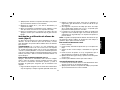 29
29
-
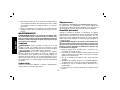 30
30
-
 31
31
-
 32
32


DeWalt D28491-B2C Manual de usuario
- Tipo
- Manual de usuario
En otros idiomas
- English: DeWalt D28491-B2C User manual
Documentos relacionados
-
DeWalt D28493N Manual de usuario
-
Black & Decker D28493N Manual de usuario
-
DeWalt D28494N TYPE 1 El manual del propietario
-
-
-
-
-
-
-
DeWalt D28499 Manual de usuario