HeatStar ER2STG100-LP El manual del propietario
- Categoría
- Calentadores espaciales
- Tipo
- El manual del propietario
Este manual también es adecuado para

— WHATTODOIFYOUSMELLGAS
• OpenWindows
•DO NOTtrytolightanyappliance.
•DO NOTuseelectricalswitches.
•DO NOTuseanytelephoneinyourhouse.Immediatelycallyourlocalgassupplierfromaneighbor’stelephone.
Followthegassupplier’sinstructions.
•Do nottouchanyelectricalswitch;donotuseanyphoneinyourbuilding.
• Installationandservicemustbeperformedbyaqualifiedinstaller,serviceagencyorthegassupplier.
• Ifyoucannotreachyourgassupplier,calltheFireDepartment.
FOR YOUR SAFETY:
Donotstoreorusegasolineorotherflammablevaporsandliquidsinthevicinityofthisoranyotherappliance.
WARNING: Iftheinformationintheseinstructionsarenotfollowedexactly,afireorexplosionmayresultcausing
propertydamage,personalinjuryorlossoflife.
ENERCOGroup,Inc.,4560W.160THST.,CLEVELAND,OHIO44135•866-447-2194
WARNING: Improper installation, adjustment, alteration, service or maintenance can cause
property damage, injury, or death. Read the installation, operating and maintenance instructions
thoroughly before installing or servicing this equipment
OPERATING INSTRUCTIONS
AND OWNER’S MANUAL
READ INSTRUCTIONS CAREFULLY:Readandfollowallinstructions.
Placeinstructionsinasafeplaceforfuturereference.Donotallowanyonewhohas
notreadtheseinstructionstoassemble,light,adjustoroperatetheheater.
Model#
2STG
ER
LANGUAGES INCLUDED
•ENGLISH
•FRENCH
•SPANISH
Heatstar ER2STG
Gas-Fired Low-Intensity Infrared Heaters Approved For
Commercial Applications
ER2STG60-100
ER2STG80-125
ER2STG125-175

GENERAL HAZARD WARNING:
FAILURE TO COMPLY WITH THE PRECAUTIONS AND
INSTRUCTIONS PROVIDED WITH THIS HEATER, CAN
RESULT IN DEATH, SERIOUS BODILY INJURY AND
PROPERTY LOSS OR DAMAGE FROM HAZARDS OF
FIRE, EXPLOSION, BURN, ASPHYXIATION, CARBON
MONOXIDE POISONING, AND/OR ELECTRICAL
SHOCK.
ONLY PERSONS WHO CAN UNDERSTAND AND
FOLLOW THE INSTRUCTIONS SHOULD USE OR
SERVICE THIS HEATER.
IF YOU NEED ASSISTANCE OR HEATER INFORMATION
SUCH AS AN INSTRUCTIONS MANUAL, LABELS, ETC.
CONTACT THE MANUFACTURER.
WARNING:
YOUR SAFETY IS IMPORTANT TO YOU AND TO
OTHERS, SO PLEASE READ THESE INSTRUCTIONS
BEFORE YOU OPERATE THIS HEATER.
WARNING:
FIRE, BURN, INHALATION, AND EXPLOSION
HAZARD. KEEP SOLID COMBUSTIBLES, SUCH AS
BUILDING MATERIALS, PAPER OR CARDBOARD,
A SAFE DISTANCE AWAY FROM THE HEATER AS
RECOMMENDED BY THE INSTRUCTIONS NEVER
USE THE HEATER IN SPACES WHICH DO OR MAY
CONTAIN VOLATILE OR AIRBORNE COMBUSTIBLES,
OR PRODUCTS SUCH AS GASOLINE, SOLVENTS,
PAINT THINNER, DUST PARTICLES OR UNKNOWN
CHEMICALS.
WARNING:
THIS PRODUCT CAN EXPOSE YOU TO CHEMICALS
INCLUDING LEAD AND LEAD COMPOUNDS, WHICH
ARE KNOWN TO THE STATE OF CALIFORNIA TO CAUSE
CANCER AND BIRTH DEFECTS OR OTHER REPRODUCTIVE
HARM. FOR MORE INFORMATION VISIT WWW.
P65WARNINGS.CA.GOV
WARNING: Fuels used in liquefied propane
gas appliances, and the products of combustion of such
fuel, can expose you to chemicals including benzene,
which is known to the state of California to cause cancer
and cause birth defects or other reproductive harm, for
more information go to www.P65Warnings.ca.gov
CONTENTS
Section1INTRODUCTION.........................................................2
Section2PLANNING.................................................................3
Section3INSTALLATION&ASSEMBLY.......................................6
Section4ENGINEERINGSPECIFICATIONS...............................12
Section5VENTING/DUCTING…………………………………………13
Section6GASPIPING..............................................................16
Section7WIRING....................................................................17
Section8OPERATIONMAINTENANCE.....................................18
Section8TROUBLESHOOTING.................................................20
Section9REPLACEMENTPARTS..............................................23
WARRANTYINFORMATION.....................................................24
2
Enerco | Heatstar ER2STG Tube Series Heater Operating Instructions and Owner’s Manual
Checking Shipment
SECTION 1:Introduction
HeatstarER2STGmodelsarelow-cost,fieldassembledinfrared
heatersthatareeasytoinstallandrequireonlyminimal
maintenance.Theyaredesignedtoprovideyearsofeconomical
operationandtrouble-freeservice.
ChecktheshipmentagainsttheBillofLadingforshortages.
Also,checkforexternaldamagetocartons.Noteany
shortages,and/orexternaldamagetocartonsontheBillof
Ladinginthepresenceofthedeliverytrucker.Thedelivery
truckershouldacknowledgeanyshortagesordamageby
initializingthis“noted”BillofLading.Immediatelyreport
anyclaimsfordamagedmaterial,orshortagesthatwerenot
evidentatthetimeofshipment,tothecarrierandyourEnerco
Group,IncFactoryRepresentative.
Installer Responsibility
Allheatersandassociatedgaspipingshouldbeinstalledin
accordancewithapplicablespecificationsandthisinstallation
madeonlybyfirms(orindividuals)wellqualifiedinthistypeof
work.Consultlocalbuildinginspectors,FireMarshalsoryour
localEnercoGroup,IncFactoryRepresentativeforguidance.
HeatstarER2STGheatersareinstalledonthebasisof
informationgiveninalayoutdrawing,whichtogetherwiththe
citedcodesandregulations,comprisethebasicinformation
neededtocompletetheinstallation.Theinstallermustfurnish
allneededmaterialthatisnotfurnishedasstandardequipment,
anditishisresponsibilitytoseethatsuchmaterials,aswell
astheinstallationmethodsheusesresultinajobthatis
workmanlikeandincompliancewithallapplicablecodes.
EnercoGroup,IncFactoryRepresentativeshavehadtraining
andexperienceintheapplicationofthisequipmentandcan
becalledonforsuggestionsaboutinstallationwhichcansave
materialandmoney.

3Operating Instructions and Owner’s ManualEnerco | Heatstar ER2STG Tube Series Heater
SECTION 2: Planning
Thefollowingcodesandinstructionsshouldbefollowedwhen
planningtheinstallationoftheHeatstarER2STGheater.In
additiontotheseinstructions,thewarningsin(Section1)must
becarefullyadheredtosinceimproperinstallationmayleadto
propertydamage,injury,ordeath.
National Standards and Applicable
Codes
Gas Codes:
Thetypeofgasappearingonthenameplatemustbe
thetypeofgasused.Installationmustcomplywithlocal
codesandrecommendationsofthelocalgascompany,
andtheNationalFuelGasCode,ANSIZ223.1–latest
revision,(sameasNFPABulletin54)ortheNaturalGas
andPropaneInstallationCode,CSAB149.1.
• Clearancebetweentheheateranditsventandadjacent
combustiblematerial(whichispartofthebuildingorits
contents)shallbemaintainedtoconformwiththeStan-
dardforInstallationofGasAppliancesandGasPiping,
NFPA-54/ANSIZ223.1–latestrevision,NationalFuel
GasCodeortheNaturalGasandPropaneInstallation
Code,CSAB149.1.
Aircraft Hangers:
Installationinaircrafthangersmustbeinaccordance
withtheStandardforAircraftHangers,ANSI/NFPA-409
– latestrevision.
• Heatersinaircraftstorageorserviceareasshallbein-
stalledataheightof10feetabovetheuppersurfaceof
wingsorengineenclosuresofthehighestaircraftwhich
maybehousedinthehanger.(Thisshouldbemeasured
fromthebottomoftheheatertothewingorengine
enclosure,whicheverishighestfromthefloor.)
• Inothersectionsofaircrafthangers,suchasshopsor
offices,heatersmustnotbeinstalledlessthan8feet
abovethefloor.
• Heatersinstalledinaircrafthangersshallbelocatedso
asnottobesubjecttodamagebyaircraft,cranes,move-
ablescaffoldingorotherobjects.
Public Garages:
Installationsingaragesmustbemadeinaccordance
withtheStandardforParkingStructures,NFPA-88A–
latestrevisionortheStandardforRepairGarages,NFPA-
88B–latestrevision.
• Heatersmustnotbeinstalledlessthan8feetabove
thefloor.Minimumclearancestocombustiblesmustbe
maintainedfromvehiclesparkedbelowtheheater.
• Wheninstalledoverhoists,minimumclearancestocom-
bustiblesmustbemaintainedfromtheuppermostpoint
onthehoist.
Venting:
Theventingmustbeinstalledinaccordancetothelatest
revisionofANSIZ223.1orCSA149.1.Partialinformation
withregardtothiscodeisprovidedin(Section5)ofthis
installationmanualwithregardtosizeandconfigura-
tionsforventingarrangements.
• Anyportionoffluepipepassingthroughacombus-
tiblewallmustbedualinsulatedorhaveanapproved
thimble.RefertotothelatestrevisionofANSIZ223.1or
CSA149.1
Hazardous Locations:
Wherethereisthepossibilityofexposuretocombustible
airbornematerialorvapor,consultthelocalFireMarshal,
thefireinsurancecarrierorotherauthoritiesforapproval
oftheproposedinstallation.
Critical Considerations
HeatstarER2STGisasuspendedheater.Therefore,its
stability,flexibility,andsafetyareveryimportant.Before
startinginstallation,besurethesystemcanmeetthe
followingrequirements.
• Maintainspecifiedclearancestocombustibles,andsafe
distancefromtheheat-sensitivematerial,equipmentand
workstations.
• Thestatedclearancestocombustiblesrepresentasur-
facetemperatureof90°F(30°C)aboveroom
temperature.Buildingmaterialswithlowheattolerance(
suchasplastic,vinylsiding,canvas,etc.)maybesubject
todegradationatlowertemperatures.Itistheinstall-
ersresponsibilitytoassurethatadjacentmaterialsare
protectedfromdegradation.
•Provideasuspensionwithverticallengthofchainor
swingingrodwhichhasatleast2inchesofhorizontal
travelforeachburnerinastraightrun.Besurethesus-
pensionsystemissufficientlyflexibletoaccommodate
thermalexpansionwhichoccursasthesystemheatsup
(seeFigure6onpage11).
• Provideaccesstoburnersforservicing,preferableon
bothsides,aboveandbehindtheburnerforremoval.
• Provideaminimumof18inchesofclearancebetween
burnersandbuildingwalls.(Alwaysobserveminimum
clearancestocombustibles.)
• Besuretheheaterhasadownwardpitchofone-half
inchper20feetawayfromtheburner.
• Providesignsinstorageareastospecifymaximumstack-
ingheighttomaintainrequiredclearancestocombus-
tibles.
•Planlocationsupports(seeFigure2A-Donpage8).
Locateasupportnearallelbows.
• Theinstallationmustconformwithlocalbuildingcodes
orintheabsenceoflocalcodes,withtheNationalFuel
GasCode,ANSIZ223.1/NFPA54ortheNaturalGas
andPropaneInstallationCode,CSAB149.1.
• Ifanexternalelectricalsourceisutilized,theheater,
wheninstalled,mustbeelectricallygroundedinaccor-
dancewiththeNationalElecticalCode,ANSI/NFPA70
orcurrentCanadianElectricalCode,CSAC22.1.
Available Venting Kits
F102848 Category I 4" Vertical Vent Kit
F102849 Category I 6" Vertical Vent Kit
F102860 Category III 4" Stainless Steel Horizontal Vent Kit

4
TABLE 1:MinimumClearancestoCombustibles(UseFigure1onpage5asaGuide)
Reflector Type Position ER2STG-100 ER2STG-125 ER2STG-175
Standard
Reflector
(Horizontal)
A
B
C
D
6”
36”
74”
36”
6”
36”
87”
36”
8”
36”
87”
36”
45°ReflectorTilt
A
B
C
E
F
18”
36”
74”
36”
60”
18”
36”
87”
36”
60”
18”
36”
87”
36”
60”
U-TubeStandard
(Horizontal)
A
B
C
D
6”
36”
74”
36”
6”
36”
87”
36”
8”
36”
87”
36”
U-TubeOpposite
45°
A
B
C
F
18”
36”
74”
60”
18”
36”
87”
60”
18”
36”
87”
60”
U-TubeFull45°
A
B
C
E
F
18”
36”
74”
36”
60”
18”
36”
87”
36”
60”
18”
36”
87”
36”
60”
Unvented AboveA 36” 36” 36”
WARNING:
FIRE OR EXPLOSION HAZARD
CAN CAUSE PROPERTY DAMAGE, SEVERE INJURY OR DEATH.
Inallsituations,clearancestocombustiblesmustbemaintained.Failuretoobserveclearancestocombustiblesmayresultinproperty
damage,severeinjury,ordeath.
Minimumclearancesmustbemaintainedfromvehiclesparkedbelowtheheater.Signsshouldbepostedinstorageareastospecify
maximumstackingheighttomaintainrequiredclearancestocombustibles.
Cautionshouldbeusedwhenrunningthesystemnearcombustiblematerialssuchaswood,paper,rubber,etc.Considerationshouldbe
giventopartitions,storageracks,hoists,buildingconstruction,etc.
TABLE1givesminimumacceptableclearancestocombustibles.ClearancesasshowninTABLE1arenotforuseinfour-sidedenclosures.
Clearances To Combustibles

5Operating Instructions and Owner’s ManualEnerco | Heatstar ER2STG Tube Series Heater
D
A
C
STANDARD REFLECTOR
A
E
C
E
45 DEGREE REFLECTOR TILT
C
A
EF
U-TUBE OPPOSITE 45 DEGREE
A
CD
U-TUBE STANDARD
C
E
A
E
U-TUBE FULL 45
BE
FRONT AND BACK CLEARANCE
Clearances To Combustibles
Figure 1: ClearancesToCombustibles(RefertoTABLE1onpage4)
A
C
EF
STANDARD REFLECTOR
D
A
C
A
C
D
“U”-Tube,Standard
A
C
D
F
“U”-Tube,Opposite45°
F
C C
AA
E
A
F
“U”-Tube,Full45°
C
AC
B
B
FrontandBackClearance

6
SECTION 3: Installation & Assembly
TUBECOUPLING(14612)
KEYFORTUBECOUPLING
(14616)
TUBEHANGER
(14585P)
HEATEXCHANGERTUBE10'
(06413)
TURBULATORBAFFLE5'(03447)
**NOTINCLUDEDWITHALLMODELS**
REFLECTOR10'
(00418A)
VENTADAPTER
(19021)
BURNERBOX

7Operating Instructions and Owner’s ManualEnerco | Heatstar ER2STG Tube Series Heater
Vent Adapter
Usedtoattachtheheat
exchangertubingtoventpipe.
Installation Procedure
Takemaximumadvantageofthebuildingupper
structure,beams,joists,purlins,etc.,fromwhichto
suspendtheheater.Thereisnouniquesequencefor
installationofthetubing.On-siteobservationwill
usuallyrevealalogicalsequence.Begintheinstallation
atthemostcriticaldimension.Thiscouldsavetime.
Watchforswingingdoors,overheadcranes,carlifts
etc.Reflectorsandtubingcanbeinstalledasyoumove
along.Carefullyadjustsystempitchateachposition
toleveltheheater.Pitchdownone-halfinchin20feet
(awayfromburner).
DON’TPressuretestthegaslineusinghighpressure(greater
than½PSIG)withoutclosingthehigh-pressureshutoff
cocks.Failuretodosowillresultindamagetothe
burners.
Burner Housing
Mustalwaysbe
installedhorizontally.
Tube and Reflector Hanger
Installimmediatelyafterfirst
coupling.
Turbulator
The60-100kER2STGutilizesa5'turbulatorwhen
operatingwitha30'tubeset
Theturbulatorislocatedattheendofthe3rdtube
Tube and Reflector Hanger
Suspendsystemfromthesehangers.
Minimumtwo(2)requiredpertube.
Reflectors
Alternateoverlapasshown
onoverview.Lengthof
reflectorandamountof
overlapisindicated.
10'2=1/2" ALUMINIZED
Heat Exchange Tubes
Suppliedin10ft.lengths.
Tube Coupling Assembly
Couplingshouldbeorientedwith
slidebarontop,andallcouplings
should“point”inthesamedirection.
AssembletheheatercomponentsasshowninFigures2a,2b,2c,2d,Optionalreflectorconfigurationsareshownin(Figure1).Install
appropriatedsuspensionhardware,beamclamps,chainorrodatpredeterminedlocations.Adjustmentofchainlengthwillprovideuniformpitch.
DO Familiarizeyourselfwithlocalandnational
codes.
Developaplannedprocedurewhichwillconservematerial
andlaboronthejob.
Checktoseethatallmaterialandequipmentisonthejob
beforestartinginstallation.
Allowforthermalexpansionofthehottube.
Installthegasconnectoronlyasshownininstructions(see
Figure14onpage16).
Haveslipjointswhererequiredbetweenreflectorstokeep
themfrombucklingorcomingapart.
Provide1sq.inchoffreeairopeningtoeach1,000BTU/hr.
ofheaterinput(butnotlessthan100sq.inches)inenclosed
spaces.Oneopeningshouldbewithin12inchesofthetop
andonewithin12inchesofthebottomoftheenclosure.
FIGURE 2: Heatstar ER2STG Overview

8
FIGURE 2A: Heatstar Model ER2STG 60-100 Assembly Overview
30 ft. Exchanger length. 31 ft. - 4 in. Total Heater length. 6 Suspension points as indicated.
FIGURE 2B: Heatstar Model ER2STG 80-125 or ER2STG 60-100
40 ft. Exchanger length. 41 ft. - 4 in. Total Heater length. 8 Suspension points as indicated.
FIGURE 2C: Heatstar Model ER2STG 80-125 or ER2STG 125-175
50 ft. Exchanger length. 51 ft. - 4 in. Total Heater length. 10 Suspension points as indicated.
FIGURE 2D: Heatstar Model ER2STG 125-175
60 ft. Exchanger length. 61 ft. - 4 in. Total Heater length. 12 Suspension points as indicated.
ALUMINIZED ALUMINIZED ALUMINIZED ALUMINIZED
18”
Typ.
18” 18” 18”
10’ 2-1/2” 10’ 2-1/2” 10’ 2-1/2” 10’ 2-1/2”
10’ 2-1/2” 10’ 2-1/2” 10’ 2-1/2”
10’ 2-1/2”
10’ 2-1/2”
18”
Typ.
ALUMINIZED ALUMINIZED ALUMINIZED ALUMINIZED ALUMINIZED
18” 18” 18” 18” 18” 18” 18” 18” 18”
10’ 2-1/2” 10’ 2-1/2” 10’ 2-1/2”
10’ 2-1/2” 10’ 2-1/2” 10’ 2-1/2”
18”
Typ.
ALUMINIZED ALUMINIZED ALUMINIZED ALUMINIZED ALUMINIZEDALUMINIZED
18” 18” 18” 18” 18” 18” 18” 18” 18” 18” 18”
(1) TURBULATOR SECTION (5')

9Operating Instructions and Owner’s ManualEnerco | Heatstar ER2STG Tube Series Heater
FIGURE 3: Heatstar ER2STG Dimensions & Suggested Mounting Heights
Turbulator
HeatExchanger Tubing
Turbulator
HeatExchanger Tubing
MinimumTotalLength(seechartbelow)
Burner Side View
Burner Ratings and Heat Exchanger Lengths: (NG and LP) Suggested Mounting Heights
Model # Rate (BTU/Hr.)
Low-High
Heat Exchanger
Length Turbulator Minimum
Total Length
Typical
Mounting
Height
ER2STG
60-100
60-100,000 30ft. 5ft. 31'4"12’-15’
60-100,000 40ft. None 41'4"12"-15'
ER2STG
80-125
80-125,000 40ft. None 41'4"14’-19'
80-125,000 50ft. None 51'4"14’-19'
ER2STG
125-175
125-175,000 50ft. None 51'4"15’-25'
125-175,000 60ft. None 61'4"15’-25'
Burner Rear View
9.25"
(23.49cm)
9.25"(23.49cm)
17.75"(45.08)
(IFNECESSARY)

10
Couplings: Tubeandtubefittingsareconnectedbywrap-
aroundcouplingswhichclampbymeansof
atapered,hammer-drivenlockmember.The
startingendsofthecouplingandlockmember
areidentifiedby1/4”holeswhichareput
togetherwhenstartingassembly.Besurethe
tubeendsareinlineandtubeendsbuttagainst
stoppin(s)insidecoupling.Theslidebaristobe
hammer-driventoapointofsecuringthecoupling
snuglytothetubes.Over-drivingwillresultin
distortionofthecouplingorslidebarliptoa
pointdecreasingtheholdingthecapabilityofthe
coupling.(SeeFigure4)
90°Elbow
ElbowFittingDimensions
FIGURE 5: Installation of Elbow & Coupling
ElbowPackage: Stk.#F106415ElbowPackageincludes:
(1)elbow,(1)couplingand(1)refelctor.
Installelbowintoradianttubesequence
whereplansindicatea90°bend
U-TubeFittingDimensions 180°U-Tube
Stk.#i ncludes:
F106414U-TubePackage
(1)U -tube,(1)couplingand(2)
radianttubesequencewhereplans
indicatea180°bend
COUPLING ASSEMBLY
Coupling (Less Key) - 14612
Key for Coupling - 14616
Tighten
Loosen
Hole 1
Coupling
Assembly
Impact
Block
Hole 2
Whenassemblingcouplingnote
thelocationofHole1andHole2
Orientcouplingsothat
theimpactblockisabove
tubecenterline.
TUBECOUPLING
KEYforCOUPLING
FIGURE 4:
(38.73 CM)
(15.24 CM)
18" (45cm)
10"
(25cm)
(10cm)
(43cm)
9" (22cm) Radius

11 Operating Instructions and Owner’s ManualEnerco | Heatstar ER2STG Tube Series Heater
Chainkit-Stk.#17370
Onechainkitwillsuspendone10ft.sectionoftubeandone10ft.
sectionofreflector.
FIGURE 7A: Tube and Reflector Hanger
FIGURE 7B: Mounting Flange / Tube Detail
1) Inserttube06413intofrontcastingtopoint(A).
2) Tightensetscrewsmarked(B)untilsnug.
3) Afterall(3)setscrewsaresnug,turneach
additional1/4turntosecuretubeinplace.
FIGURE 8: Burner Box / Transition Tube Detail
FIGURE 6: Typical Suspension Details
Locknut
Washer
WoodBeam
Washer
ScrewHook
min.3/8"(10mm)
I-Beam
Beam
Clamp
AsReq'd
S-Hook
BarJoist
Clip
Truss
Concrete
Beam
Anchor
MountingFlange
CapScrew
Stk.98012
SplitLockWasher
Stk.#98527
Gasket
Stk.#12397
Burner Box
(flameobservation
windowfacingdown)
horizontal reflector position (standard)
angle mounting ring
radiant tube
horizontal mounting ring
hanger
reflector
top
side 45° reflector position (optional)
below
A
B
FIGURE 9: Reflector End Cap
Partslist
100419ReflectorEndCap(Qty1)
209369SpringClip(Qty4)
FlangeKit#06428XL
KitIncludes:Flange,Screws(4),LockWashers(4),Gasket(1)
B

12
SECTION 4
Engineering Specifications
ThetotalheatingsystemsuppliedshallbedesigncertifiedbyCSA
underthelatestrevisionofANSIZ83.20andCSA2.34.
A. Burner & Burner Controls
1. Burnersshallbecapableoffiringwithoneofthefueloptionsas
specifiedonthepurchasedocuments:NaturalGasorLP.
2. Burnersshallbesuppliedtofireatanyoneoftheinputratesas
specified.
ER2STG60-100 60,000-100,000BTU/Hr.
ER2STG80-125 80,000-125,000BTU/Hr.
ER2STG125-175 125,000-175,000BTU/Hr.
3. Burnershallbeequippedwithadirectsensesilicon-carbidehot
surfaceignitioncontrolsystemwith100%shut-offignitiondevice.
Powersuppliedtoeachheatershallbe120V,60Hz,singlephase.
Burnersshallberatedfor1.0Amp(run)and5.0Amp(start.)
4. Burnershallbeequippedwiththermaloverloadmotorprotec-
tion,balancedairrotor,combustionairprovingsafetypressure
switch,andviewingwindowforflameobservation.
5. Whenspecified,incontaminatedenvironments,theburnershall
becapableofsupplyingoutsideairtoeachburnerforthesup-
portofcombustion.
6. Allburnersshallbepre-wiredwithagroundedelectrical
cordandplug.
7. Lowvoltage2-stagethermostatrequiredforcorrect2-stage
burneroperation.
B. Heat Exchanger
1. Radianttubingshallbe4”diameteraluminizedsteelsuppliedin
10ft.sections.Sectionsshallbejoinedwithstainlesssteelwrap-
aroundcouplings.
2. Reflectortobeofaluminummaterialanddesignedtodirectall
radiantoutputbelowhorizontalcenterlineofradianttube.
3. Heatersshallbeventedaccordingtomanufacturer’s
recommendations.
Gas INLET pressure:
Natural Gas: 4.6” W.C. Min
11.0” W.C. Max
LP Gas: 11.0” W.C. Min
14.0” W.C. Max
1/2”NPTGasConnectorSize
Electrical Rating:(AllModels)
120V-60Hz
1.0AMP(Run)5.0AMP(Start)
Dimensions:
Flue Connection Size…………………4”
Outside Air Connection Size………4”
MANIFOLD PRESSURE
ER2STG 60-100
LOW FIRE
( MIN. RATE)
HIGH FIRE
(MAX RATE)
NATURALGAS-INCHESW.C. 1.3" 3.5"
PROPANE-INCHESW.C. 3.5" 10.5"
MANIFOLD PRESSURE
ER2STG 80-125
LOW FIRE
( MIN. RATE)
HIGH FIRE
(MAX RATE)
NATURALGAS-INCHESW.C. 1.7" 3.5"
PROPANE-INCHESW.C. 4.2" 10.5"
MANIFOLD PRESSURE
ER2STG 125-175
LOW FIRE
( MIN. RATE)
HIGH FIRE
(MAX RATE)
NATURALGAS-INCHESW.C. 2.2" 3.5"
PROPANE-INCHESW.C. 5.8" 10.5"
Gas pressure at MANIFOLD:
1/2”NPTGasConnectorSize

13 Operating Instructions and Owner’s ManualEnerco | Heatstar ER2STG Tube Series Heater
SECTION 5
Venting / Ducting
General Requirements
Thisheatermustbeventedinaccordancewiththespecifications
containedinthismanualandwiththefollowingnationalcodes
andanystate,provincialorlocalcodeswhichmayapply:
• RefertoNationalFuelGasCodeNFPA54/ANSIZ223.1-latest
revision.
• CANADA:RefertoNaturalGasandPropaneInstallationCode
CSAB149.1-latestrevision.
Theheatermaybeventedtotheoutdoorseitherverticallyor
horizontally.
Optionaloutsideairsupplymaybedirectedtotheheater
horizontallyorvertically.
Besurethatthemethodselectedforventingheatercomplies
withallcodesasrequiredforeachparticularlocation
Theuseofsingle-wallventpipe(26gauge)isrecommended.A
sectionofdouble-wallventpipeisrecommendedwhenpassing
throughtherooforwall.
Exhaustendofheaterwillaccepta4'(10cm)ventpipeusing
theventadapter.Installtheventadapterwiththeseamontop,
secureallventjointswithaminimumof3#8x3/8"sheetmetal
screwsandsealalljointsusingahightemperaturesilicone
sealant.
Ifcondensationintheflueisaproblem,thefluelengthshould
beshortenedorinsulated.
Ventpipemustbeslopeddownwardawayfromtheburner
1/4"(.6cm)forever10'(3m).
VENTLENGTHS:
• Maximumtotalventlengthallowedinthirty(30’)feet.
• Maximumoutsideairsupplyductallowedthirty(30’)feet.
• Maximumtotalventlengthplusoutsideairsupplylength
shallnotexceedfifty(50’)feet.
NOTE:
Atotaloftwo(2)elbowsareallowedforventand
outsideairsupplycombination.Subtract5'feetperadditional
elbowfrommaximumlengthallowedif3ormoreelbowsare
used.
Installaminimum18"(30cm)straightlengthofductforair
intakeorventbeforeanyTeeorelbow.
Alternative Arrangements / Optional Equipment for Venting
Unvented Operation
a) Sufficientventilationmustbeprovidedintheamountof4
CFMper1,000BTU/hr.firingrate.
b) RefertoANSIZ223.1-latestrevision,NFPA-54andlocal
codesforadditionalinformation.
c) Useofoptionaloutsidecombustionairisnotrecommended
withunventedheatersduetopressureconsiderations.Refer
topage16
a) Four(4”)inchO.D.fluepipeisrequired.Thirty(30’)feet
maximumlengthisrecommended.
b) Allfluejointsshouldbesealedusingsuitableproductsuch
asGeneralElectricRTV106orPermatexForm-A-GasketRed
HighTemperatureSiliconeAdhesiveSealant.
c) Donotinstallanyelbowor45fittingtobringventlower
thanthehorizontaltubesystem.
d) Ventterminalshouldbeinstalledataheightsufficientto
preventblockagebysnow.
1) Ventmustexitbuildingnotlessthanseven(7’)feet
abovegradewhenlocatedadjacenttopublicwalkways.
2) Ventmustterminateatleastthree(3’)feetaboveany
forcedairinletlocatedwithintenfeet(10’).
3) Ventmustterminateatleastfour(4’)feetbelow,four
(4’)feethorizontallyfrom,orone(1’)footaboveany
door,window,orgravityinletintoanybuilding.
4) Ventterminalshallbelocatedatleasttwelve(12”)inches
fromanyopeningthroughwhichventgasescouldenter
thebuilding.
5) Ventterminalmustbebeyondanycombustibleover
hang
Vertical Venting
a) Four(4”)inchO.D.fluepipe,maximumthirty(30’)feet
inlengthmaybeusedasshownwithapprovedventcap.
(SeeGeneralRequirementsonthispageforadditional
information.)
b) Aninsulatedthimblemayberequiredtopassthrough
combustiblestructures(checklocalcodes).
c) Allfluejointsshouldbesealedusingsuitableproducts(see
recommendationforhorizontalventing.)
Common Venting
a) Horizontalruntoventmustneverexceed75%ofthevertical
heightofthevent.RefertoANSIZ223.1-latestrevision,
NFA-54forproperventsizesandinstallation.
b) Openareaofcommonventmustequalthesumoftheopen
areaofindividualventsconnectedtoit.(Seechartbelow
anddiagrams-page14.)
c) Usedoublewallventasrequired(checkcodes.)
d) Alljointsmustbesealedusingsuitableproducts.
e) Connectionstocommonstackmustbepositionedtoavoid
directoppositionbetweenstreamsofcombustiongases.
COMMON VENTING - (2) Heaters (Horizontal and Vertical)
Model# H=6ft. H=8ft. H=15ft.
ER2STG60-100 D=8" D=8" D=7"
ER2STG80-125 D=10" D=10" D=8"
ER2STG125-175 D=10" D=10" D=8"
Horizontal Venting
This heater, when horizontally vented, must be installed with the
approved venting system. For horizontal venting installations these
tube heater are certified as a category III appliance.
This heater, when vertically vented, must be installed with the
approved venting system. For vertical vent installations, ER2STG
60-100 model and ER2STG 80-125 model are category I
appliances. The ER2STG 125-175 model is only Category I when
vented vertically with 6" (15.25cm) diameter vent pipe.

14
FIGURE 12: Common Roof Venting
Type"B"Ventrequiredoutdoors.
VentAdapterStk.#19021
OutsideWall
Securealljointswith3(minimum)#8x3/8"
sheetmetalscrewsandsealalljoints.
H
VentCap
WallThimble
(IfApplicable)
BurnerBox
BurnerBox
HORIZONTAL COMMON VENTING
VERTICAL COMMON VENTING
SIDE VIEW
TOP VIEW
Type "B" Vent required outdoors.
Vent Adapter Stk. #19021
At least 1/4" per foot rise or pitch
must be maintained on horizontal
runs from heater to vent.
Roof
Secure all joints with 3 (minimum) #8 x 3/8"
sheet metal screws and seal all joints.
H
Approved Vent Cap
Type "B" Vent required outdoors.
Vent Adapter Stk. #19021
Outside Wall
H
Vent Cap
Flashing
Wall Thimble
(If Applicable)
Burner Box Burner Box
Burner Box
Burner Box
Burner Box
Burner Box
D
Burner Box Burner Box
D
4” Aluminized steel Heat Exchange Tube
4” Aluminized steel Heat Exchange Tube
D

15 Operating Instructions and Owner’s ManualEnerco | Heatstar ER2STG Tube Series Heater
FIGURE 10: Unvented Operation
36”
36”
A
1. Ventilationequalto4CFMper1,000BTU/HRfiringratemust
beprovidedinunventedheaterinstallations
2. FordimensionsA"unvented"referto(Figure1-Minimum
ClearancestoCombustibles.)
3. Thisheaterrequiresventilationinthebuildingtodilutethe
productsofcombustionandprovidefreshairforefficient
combustion.
FIGURE 10b: Double Wall
Doublewallventrun
Doublewallterminalend
FIGURE 11: Vertical Venting
18"(45cm)
18" (45cm) Min. 3'-0" (91cm) Min.
8"(20cm) to 10"(25cm) Max.
6' (182cm) Min.
FIGURE 10A: Single Wall
Singlewallventrun
Singlewallterminalend
18" (45cm) Min. 3'-0" (91cm) Min.
6' (182cm) Min.
2"(5cm) Clearance thimble
2"(5cm) Clearance thimble
required when u pipe
extends through
combustible materials
(91cm)
(91cm)
VentAdapter

16
Outside Combustion Air Supply
TheHeatstarER2STGheaterisapprovedforinstallationwith
anoutsideairsupplysystem.Somecompoundssuchas
halogenatedhydrocarbonsorothercorrosivechemicalsinthe
aircanbedrawnintotheequipmentandcauseanaccelerated
rateofcorrosionofsomeoftheheatercomponents.Theuse
ofsuchchemicalcompoundsneartheenclosureshouldbe
avoided.
IMPORTANT: If the building has a slight negative
pressure or contaminants are present in the air, an
outside combustion air supply to the heaters is strongly
recommended.
Foranoutsideairsupply,afour(4”)inchO.D.singlewallpipe
maybeattachedtotheheater.Theductmaybeuptothirty
(30’)ft.maximumlengthortwo(2’)ft.minimumlengthwith
nomorethantwo(2)elbows.(SeeGeneralRequirementson
page15foradditionalinformation.)
Theairsupplyductmayhavetobeinsulatedtoprevent
condensationontheoutersurface.Theoutsideairterminal
shouldbesecurelyfastenedtotheoutsidewallbydrillingfour
(4)1/4”diameterholesintheoutsideflange;woodscrewsor
boltsandexpansionsleevesmaybeusedtofastenterminal.
PVCPipe,“DryerHose”,orequivalentmaybeusedinsteadof
standardventpipe.
FIGURE 13: Non-Pressurized Outside Air Supply Duct
SECTION 6
Gas Piping
Readapplicablewarningsin(Section1)beforeproceedingwith
GasPipeinstallation.Improperinstallationmayresultinproperty
damage,severeinjury,ordeath.
Meterandservicemustbelargeenoughtohandlealltheburners
beinginstalledplusanyotherconnectedload.Thegaslinewhich
feedthesystemmustbelargeenoughtosupplytherequiredgas
withamaximumpressuredropof1/2”watercolumn.Whengas
pipingisnotincludedinthelayoutdrawing,thelocalgassupplier
willusuallyhelpinplanningthegaspiping.
A1/2”tappingateachburnerlocationmustbelocatedandoriented
asshownin(Figure14).Tochecksystempressure,putaplugged
1/8”NPTtappinginthegaslineattheconnectiontotheburner
farthestfromthesupply.Beforeconnectingtheburnerstothe
supplysystem,verifythatallhighpressuretestingofthegaspiping
hasbeencompleted.Donothighpressuretestthegaspipingwith
theburnersconnected.
Followtheseinstructionstoensureaprofessionalgassupply
installation:
• Supportallgaspipingwithsuitablepipehanging
materials.
• Usewroughtironorwroughtsteelpipeandmalleable
ironfitting.Allpipefittingsshouldbenewandfree
fromdefects.Carefullyreamthepipeandtubingends
toremoveobstructionsandburrs.
• UseL.P.gas-resistantjointcompoundonallpipe
threads.
• Checkthepipeandtubingendsforleaksbefore
placingheatingequipmentintoservice.When
checkingforgasleaks,usesoapandwatersolution:
NEVER USE AN OPEN FLAME.
Installtheflexgasconnectorasshown.Theflexgasconnector
accommodatesexpansionoftheheatingsystemandallowsforeasy
installationandserviceoftheburner.
FIGURE 14: Gas Line Connection with Stainless Steel Flex Gas
Connector
Shut-OffValvemustbeparallel
toburnergasinlet.The2”
displacementshownisforthecold
condition.Thisdisplacementmay
reducewhenthesystemisfired.
Shut–offValve
12 "
2"
1/2"StainlessSteelFlexGasConnector
Stk.#16401
90°
45°
0°
45°
4" (10 cm)
Seal All Joints
Heater Movement
Heater Movement
Heater Movement
Heater Movement
Outside Air
Terminal
Flex Pipe
6" (15 cm) to
12" (30 cm) Long
Flex Pipe
6" (15 cm) to
12" (30 cm) Long
Flex Pipe
6" (15 cm) to
12" (30 cm) Long
Outside Air
Terminal
NOTE:
Flue pipe requires additional
support. Flex pipe will not
support riser and outside
air terminal
Vertical Outside Air
Horizontal Outside Air
FIGURE 14A: Incorrect Gas Line Connection with Stainless
Steel Flex Gas Connector

17 Operating Instructions and Owner’s ManualEnerco | Heatstar ER2STG Tube Series Heater
THERMOSTAT CONNECTION
24V
W1
W2
LOW HEAT
HIGH HEAT
R
W1
W2
TUBE BURNER CONNECTIONS INTERNAL THERMOSTAT WIRING
SECTION 7
Wiring
Heatersarenormallycontrolledbythermostats.Heatersmustbe
electricallygroundedinaccordancewiththeNationalElectrical
Code,ANSI/NFPA70orcurrentCanadianElectricalCode,CSA
C22.1.
• Ifanyoftheoriginalwireassuppliedwiththeappliancemust
bereplaced,itmustbereplacedwithwiringmaterialhavinga
temperatureratingofatleast105°Candratedfor600V
• Eachburnermustbeelectricallygroundedinaccordancewith
theNationalElectriccodeANSI/NFPA-70-latestversion NOTE:
• Connectingthetoptwoterminalsofthebushing
locatedatthebottomleftofthebackofthe
burnerboxwillgiveyoulowfire
• Connectallthreeoftheterminalsforhighheat
L1
N
Earth Ground
GV
M
T1
PCB1
S1/240
S1/120
N
L1
S2/FS
PSW
W
MV1
GRND
blk
wh
blk
grn
Pressure Switch
24 V
SW1
C1
blk
wh
grn
Primary
Secondary
FC+ FC-
LED
R
F2/IND
F1/120
red
To Thermostat
24V
W1 W2
grn
red
wh
grn
brn
wh
red
red
Flame Sense
Burner
HSI
wh
wh
blk
wh
wh
yellow
SW1 - Panel Interlock Switch
C1 - 1.5 ufd @ 450 volts
Wire is AWG18 Stranded @ 600 volts - 105 degrees C
Crimp Caps are # CE5 - 105 degrees C
(Neutral Connection Not Needed in this Configuration)
blue
24 VAC
blk
grn
WIRING DIAGRAM
BURNER BOX CONNECTION INTERNAL THERMOSTAT WIRING
FIGURE 18A
FIGURE 18B

18
Sequence of Operation
1. Turnthethermostatup.Whenthethermostatcallsforheat,
blowermotorwillenergize.
2. WhenthemotorapproachesnominalrunningRPM,theair
provingswitchclosesandactivatestheignitionmodule.
3. Theignitionmodulethenenergizesthehotsurfaceigniterfor
atimedwarm-upperiod(approximately45to60seconds.)
4. Afterthewarm-upperiod,thegasvalveisenergized.
5. Ifaflameisdetected,thegasvalveremainsopen.Whenthe
callforheatissatisfied,andthesystemcontrolmechanism
de-energizestheburnerlinevoltagesupply,thegasvalves
areturnedoff.
6. Ifnoflameisdetectedonathree-trialmodule,thegas
valveisclosed,andapurgeperiodbegins.Afterthepurge,
themoduleactstopowertheigniterforasecondwarm-
upperiod,andasecondtrialforignitionperiod.Ifflameis
stillnotestablished,athirdandfinalpurge,warm-up,and
trialcyclebegins.Afterthreetrials,themodulewilllockout
untilreset.Resetisaccomplishedbyremovingpowerfrom
themoduleforatleastfive(5)seconds(thermostatcycle
required.)
7. Ifflameisestablishedandlostonthefirstorsecondtrial,
thegasvalveisturnedoff,apurge,warm-up,andtrialfor
ignitionwilloccuronathree-trialmodule,onlythreetrialsfor
ignitionareallowedperthermostatcycle.
Maintenance
Forbestperformance,thefollowingmaintenanceproceduresshould
beperformedbeforeeachheatingseason:
1. Besuregasandelectricalsupplytoheaterareoffbefore
performinganyserviceormaintenance.
2. Checkconditionofblowerscrollandmotor.Dirtanddustmaybe
blownoutwithcompressedair,oravacuumcleanermaybeused.
Whenusingcompressedair,donotexceed30psiinordertonot
damagefragilehotsurfaceigniter.
3. Checkconditionofburner.Carefullyremoveanydustor
debrisfrominsidetheburnerboxorburnercup.
4. Inspecttheigniter.Replaceigniterifthereisexcessivecarbon
residue,erosion,breakageorotherdefects.
5. Checktheinsideofthefiringtubewithaflashlight.Ifcarbon
orscalearepresent,scrapeoutthedepositswithawire
brushorrod,ormetalplateattachedtoawoodenpole.
6. Checktoseethattheburnerobservationwindowisclean
andfreeofcracksorholes.Cleanorreplaceasnecessary.
7. Checkthefluepipefordirt.Aftercleaningasnecessary,re-
attachthefluepipetotheheater.
8. Outsidesurfacesofheatermaybecleanedbywipingwitha
dampcloth.
9. Aqualifiedserviceagencyshouldbecontactedforservice
otherthanroutinemaintenance.
10. Checkventterminalandfreshairinlettoseethattheyhave
notbeenblockedduringthenon-heatingseason.Ifeither
pipeisrestricted,theairswitchwon’tclose,resultingina
no-heatsituation.
SECTION 8
Basic Operation of 2-Stage Tube Heater
•UnitfiresatratesdesignatedasLowandHigh
• Firerateisdeterminedbythermostat
InitialStart:
Ifthermostatismorethan2degreesabovetheroom/
spacetemperature,theheaterwillstartandgointohighfire
range.Theunitwillstayinthehighrangeuntilthespaceair
temperaturereachesthethermostatset-point.Theheaterwill
shutoff.
Astheroom/spaceairtemperaturedecreasesbelowthe
thermostatsetpoint(approximately1degree)theheaterwill
comeonandfireuntilthethermostatsetpointisreached.
Iftheroom/spaceairtemperatureexperiencesarapid
decreaseinairtemperature(below3degreesfromsetpoint)
theheaterwillcomeonandfireatthehighrateuntiltheset
pointisreached.
LADDER DIAGRAM
L
N
24V
M
C1
Panel Interlock
F2/IND
F1/120
(Control PCB)
HSI
L1 S1/120
(Control PCB)
PCB
L1
PCB
S2/FSL1
Burner
Flame Sense
T1
115V
PCB
R
PCB
PSW
Pressure Switch
W1
W2
T'Stat
W
MV1
(Control PCB)
Gas
Valve
Earth &
Chassis Ground
FIGURE 18C
Operation & Maintenance
HIGH ALTITUDE
Heaters may be fired at full input up to 2000 ft. (610m) above sea level. Above 2000 ft. (610m) a high altitude conversion kit may be required
to ensure proper burner performance, please consult the manufacturer. Be prepared to answer factory questions regarding: type of fuel for the
proposed appliance conversion, gas pressure available at site, and specific altitude at site. The conversion shall be carried out by a
manufacturer’s authorized representative, in accordance with the requirements of the manufacturer, provincial, or territorial authorities having
jurisdiction and in accordance with the requirements of the CSA B149.1 or CSA149.2 installation codes.

19 Operating Instructions and Owner’s ManualEnerco | Heatstar ER2STG Tube Series Heater
Burner Does Not 1.Checkgroundwirecontinuity.
Stay Lit: 2.Checkburnerinternalwiringforreversed
leads.
3. Checkinsulationontheigniterleads.
4. Cleanorreplaceflamesensor.
5. Replacemoduleifnecessary.
IGNITION MODULE LED Status
TheHeatstarER2STGseriesTubeHeaterisequippedwithaIgnition
module.Thisignitionmodulehasabuilt-indiagnosticprogram,
whichwillassistintroubleshootingintheeventofavalve-related
problem.TheLEDor(LightEmittingDiode)islocatedontheignition
moduleasshownindiagrambelow.TheLEDstatusindicationsare
listedbelowtohelpwiththetroubleshooting.
FIGURE 19:
Off Nopowertothecontrol
ON ControlFault
1-Flashes AirflowFault
2--Flashes FlameSenseFault
3-Flashes IgnitionLockout.
Troubleshooting
CAUTION:BeforeopeningtheHeatstar
ER2STGburnerdoorforanytypeofservice,be
surethegassupplyhasbeenshutoffatthe
heaterandtheelectricalcordfromtheburner
boxhasbeenunplugged.
Blower Motor 1.Isthethermostatcallingforheat?Isthere
Fails to Run: 120Vattheburnerreceptacle?
2. Checkblowersidedoorforseal.Checkdoor
switch.Replaceifnecessary.
3. Checkblowerforobstructions.Replace
blowerifnecessary.
Igniter 1.Checkigniterfordamage.Replaceif
Does Not Glow: necessary.
2. Checkvoltageandresistanceatigniter.
(Voltageshouldbe120V.Resistanceshouldbe
40-75ohms.)
3. Checkforobstructionstotheairinletand
outlet.
4. Checkwiringandhoseconnectionstothe
airswitch.Replaceifnecessary.
5. Checkvoltagesattransformerprimaryand
secondary.Replacetransformerormoduleif
necessary.
Valve Does Not Gaspressuredownstreamofgascontrolcan
Come On: bemeasurebyusingamanometerand
connectingtopressuretaponcontrol/
1. ChecktoseeifmanualvalveheaterisON.
2. Checktoseeifmanualvalveknobonheater
gascontrolinON.
3. Supplygaspressurecanbecheckedat
1/8”NPTpressuretappingonheaterexternal
manualvalve.
4. Checktoseeifgascontrolisopening:no
manifoldpressureindicatesvalveisclosed.
Ifthevalveisclosed,eitherthegasvalveorthe
ignitionmoduleisfaulty.
WARNING:Donotdisconnectgroundleads
insideheater.Donotinterchangegrounded
andungroundedleadsontransformeror
ignitionmodule.
Burner Does Not 1.Checktoseeifgaslineswereproperly
Light: purgedofair.
2. Checkinletandoutletgaspressureduring
ignitionperiod.
Naturalinletpressureshouldbe4.6”
Naturaloutletpressureshouldbesetaccording
tochartonpage12.
LPinletpressureshouldbe11.0”
LPoutletpressureshouldbesetaccordingto
chartonpage12.
3. Checkforproperorificeandairplate.
IGNITION MODULE
LED

20
SECTION 8: Troubleshooting Guide. Heatstar ER2STG
START
Turnonthermostat
Doesblowerturn
on?
Yes
Doestheigniter
warmupandglow
red?
Yes
No
CheckThermostat
andWiring.Isthe
powersupplytounit
120V?
No
Findthesource
oftheelectrical
problem
CheckLEDindicatoronIgnitionControlfor
indicationoffault.RefertoIgnitionModule
testingonpage19todetermineproblem.
No Istheairintakeor
exhaustblocked?
Yes
RemoveObstruction
Checkwiringand
connections
No Istheignitor
damaged?
No
Checkvoltageat
ignitor.Isit120V
duringignition
cycle?
Yes Isblowersidedoor
inplace?
No
Replacedoor
No
Checkwiringand
hoseconnectionto
airswitch.Arethey
OK?
Yes
Isthevoltageat
thetransformer
secondary24V?
No
Isthevoltageatthe
transformerprimary
120 V
Replaceignitor.
Yes
No
Istheresistance
throughigniter40
to75ohms?
Removedoor.Is
voltageatdoor
switch120?
Yes
No
Checkvoltageat
IgnitionControl
Replacewiringand/
orhoseconnection.
No
Jumperwiresat
pressureswitch.
Doestheignitor
glowred?
Yes
ReplacetransformerYes
Checkwire
connections.
Yes
Depressswitch.
Doesblowercome
on?
Yes Yes
No
Checkvoltageto
motor.Isit120V?
Yes
Istheblowerfan
obstructed?
No
Replaceblower
motor.
Replacepressure
switch.
Yes
ReplaceIgnition
Module.
No
CheckLEDindicatoronIgnitionModulefor
indicationoffault.RefertoIgnitionControl
testingonpage19todetermineproblem.
Checkdoorfit.If
damaged,replace
door.
Replaceswitch.
No
Removeobstruction
Yes
Afterignitorwarm-
upperiod,doesthe
valveclick?
Yes
Doestheburner
light?
Yes
Doestheburner
stayon?
Yes
Doestheburner
rununtilthecall
forheatends?
Ifaproblemstillexists,contactEnercoGroup,IncTechnicalProducts
CustomerService1-866-447-2194
No
TheIgnitionModulechecksthestatusoftheblowerprovingswitchcontactsmustseeachangeinthe
contactwitheveryfiringcycle.Placingajumperattheswitchoutofsequencewillresultinafaultwith
theLEDindicatorflashingtwotimes.
Werethegaslinespurgedofair?
No No
Yes
Checkinletgaspressure.Ispressurecorrect?
Refertopage12forcorrectpressureforunit.
Yes
Checkinletgasshutoff.Adjustregulator.
Contactgassupplier
Isthecontinuityof
thegroundwire
OK?
No
Theswitchonthegasvalvemustbeintheon
positionandthelinepurgedofair.
No
Repairwiring.
No
Checkthecontinuityofthegroundwire.
Checkthethermostat.
Checkoutletgaspressureduringignitioncycle.
Refertopage12forcorrectpressure
Yes
Adjusttoproperpressure.
No
AreL1andL2
reversed?
Yes
Yes
Repairwiring
Isthewiringatthe
IgnitionModule
OK?
No
Repairwiring
Istheinsulationon
thesensorleadOK?
No
Repairwiring
No Yes Yes
Arethewiresto
theIgnitionControl
OK?
Yes
ReplaceIgnition
Module.
No Replace/repairwires.
Yes
Checkforproper
burnerorificeand
airplate.
Isthesensor
positioned
properly?
Yes
Isthesensordirty?
No
ReplaceSensor
No Repair/Replace
Yes
Cleansensor.
Afaultindicationofthreeflashesmayindicate
thattheflamesensingcircuitisnotfunctioning
properly.Performthefollowingseriesofchecks
tocorrecttheproblem.
No

21 Operating Instructions and Owner’s ManualEnerco | Heatstar ER2STG Tube Series Heater
SECTION 9: Replacement Parts for Heatstar ER2STG Tube Heaters
1
6
2
7
8
4
10
935
ER2STG 60-100
Item Stock # Description QTY Item Stock# Description QTY
1 F102600 ER260-100NG/BRN&ContBox 1 6 02753 FrontFlange 1
F102602 ER260-100LP/BRN&ContBox 1 7 14 612 TubeCoupling 2
2 F106401XL ER260-100,/TubeSet-30' 1 8 14 616 KeyforTubeCoupling 2
06413 TubeH.E.4"O.D.X10' 3 9 0 0 419 ReflectorEndCap 2
3 00418A Reflector 3 10 09369 SpringClips 8
403447 TurbulatorBaffle5' 1
514585P Hanger 4
ER2STG 60-100 ER2STG 80-125
Item Stock # Description QTY Item Stock# Description QTY
1 F102600 ER260-100NG/BRN&ContBox 1 1 F102605 ER280-125NG/BRN&ContBox 1
F102602 ER260-100LP/BRN&ContBox 1 F102607 ER280-125LP/BRN&ContBox 1
2 F106406XL ER260-100,/TubeSet-40' 1 2 F106406XL ER260-125,/TubeSet-40' 1
06413 TubeH.E.4"O.D.X10' 4 06413 TubeH.E.4"O.D.X10' 4
602753 FrontFlange 1 3 02753 FrontFlange 1
414 612 TubeCoupling 1 4 14 612 TubeCoupling 1
514 616 KeyforTubeCoupling 1 5 14616 KeyforTubeCoupling 1
6 00418A Reflector 4 6 00418A Reflector 4
714585P Hanger 8 7 14585P Hanger 8
80 0 419 ReflectorEndCap 2 8 0 0 419 ReflectorEndCap 2
909369 SpringClips 8 9 09369 SpringClips 8
8
967
1
3
2
45

22
ER2STG 80-125 ER2STG 125-175
Item Stock # Description QTY Item Stock# Description QTY
1F102605 ER280-125NG/BRN&ContBox 1 1 F102610 ER2125-175NG/BRN&ContBox 1
1F102607 ER280-125LP/BRN&ContBox 1 1 F102612 ER2125-175LP/BRN&ContBox 1
2 F106407XL TubeSet-50' 1 2 F106407XL TubeSet-50' 1
06413 TubeH.E.4"O.D.X10' 3 06413 TubeH.E.4"O.D.X10' 3
302753 FrontCasting 1 3 02753 FrontCasting 1
414 612 TubeFlange 2 4 14 612 TubeFlange 2
514 616 KeyforTubeCoupling 2 5 14616 KeyforTubeCoupling 2
6 00418A Reflector 5 6 00418A Reflector 5
714585 Hanger 10 714585 Hanger 10
80 0 419 ReflectorEndCap 2 8 0 0 419 ReflectorEndCap 2
909369 SpringClips 8 9 09369 SpringClips 8
1
3
2
7
5
4
6
9
8
1
23
7
6
45
9
8
ER2STG-175
Item Stock # Description QTY Item Stock# Description QTY
1F102610 ER2125-175NG/BRN&ContBox 1 5 14 616 KeyforTubeCoupling 5
1F102612 ER2125-175LP/BRN&ContBox 1 6 00418A Reflector 6
2 F106403XL TubeSet-60' 1 7 14585P Hanger 12
06413 TubeH.E.4"O.D.X10' 6 8 00 419 ReflectorEndCap 2
302753 FrontFlange 1 9 09369 SpringClips 8
414 612 TubeCoupling 5

23 Operating Instructions and Owner’s ManualEnerco | Heatstar ER2STG Tube Series Heater
ITEM# EGI # DESCRIPTION QTY
17 05508XL 175/125KAIRPLATE 1
18 02844 GASVALVEBRACKET 1
19 00021 GASVALVE 1
20 02758 GASVALVEOUTLETFITTING 1
21 17389 GASMANIFOLDWITHGROMMET 1
22 02720 ORIFICEHOLDERFITTING 1
23 985 41 ORIFICEHOLDERFLATWASHER 1
24 05712 100/60ORIFICE(NG) 1
25 05733 100/60ORIFICE(LP)
26 05703 125/80ORIFICE(NG) 1
27 05730 25/80ORIFICE(LP)
28 05799 175/125ORIFICE(NG) 1
29 05725 175/125ORIFICE(LP)
30 98547 EXTERNALTOOTHWASHER 1
31 02371 BURNERCUP 1
32 10391A DOORSWITCH 1
ITEM# EGI # DESCRIPTION QTY
33 02721 2-TERMINALBUSHING 1
34 07376 BLOWER 1
35 123 95 BLOWERGASKET 1
36 02718 BLOWERSCREEN 1
37 02795 SIGHTWINDOW 1
ITEM# EGI # DESCRIPTION QTY
1 02716XL ENCLOSURE 1
2 02725XL CONTROLSIDECOVER 1
3 02749XL MOTORSIDECOVER 1
412 397 FRONTFLANGEGASKET 1
502753 FRONTTUBEFLANGE 1
602835 IGNITIONMODULE 1
7 08364A TRANSFORMER 1
810 413 A 125/80&100/60PRESSURESWITCH 1
910 414 A 175/125PRESSURESWITCH 1
10 02797 HOTSURFACEIGNITER 1
11 02730 FLAMESENSORROD 1
12 02847 THERMOSTAT3TERMINALBUSHING 1
13 99101 ELECTRICALJUNCTIONBOX 1
14 02747 BLOWERINTAKEFLANGE 1
15 05510XL 100/60KAIRPLATE 1
16 05500XL 125/80KAIRPLATE 1
2
6
12
13
14
7
10
11
8
9
14
5
3
15
16
17
24 26
23 22 21
20
19
18
-
30
31
32
33
34 35 36
37
Stock Number Description
F102601……………………………………Thermostat
17370………………………………………ChainKit
16401………………………………………24"StainlessSteelFlexible
16405………………………………………1/2"x24"3/4"StainlessSteel
F106414……………………………………180U-TubeAccessoryKit
F106415……………………………………90ElbowAccessoryKit
06430………………………………………VentCap
00438………………………………………SideReflectorkit
01376………………………………………DeflectorKit(5')
19031………………………………………Turnbuckle5/16"-18"
ACCESSORIES:

24
WARNING:
USEONLYMANUFACTURER’SREPLACEMENTPARTS.USEOFANYOTHERPARTS
COULDCAUSEINJURYORDEATH.REPLACEMENTPARTSAREONLYAVAILABLE
DIRECTFROMTHEFACTORYANDMUSTBEINSTALLEDBYAQUALIFIEDSERVICE
AGENCY.
FOR INFORMATION REGARDING SERVICE OR PARTS:
Contactyourlocalheatingservicetechnicianordealer.
FOR ADDITIONAL INFORMATION:
PleasecallToll-Free866-447-2194—www.heatstarby.com
Ourofficehoursare8:00AM—5:00PM,EST,MondaythroughFriday.
Pleasehavethemodelnumber,serialnumberanddateofpurchaseready.
LIMITED WARRANTY
Thecompanywarrantsthisproducttobefreefromimperfectionsinmaterialor
workmanship,undernormalandproperuseinaccordancewithinstructionsofTheCompany,
foraperiodof10yearsfromthedateofdeliverytothebuyerwiththefollowingexceptions.
• Forinstallationinacarwashandinareaswithexposuretocorrosivechemicals,suchas
ammonia,chlorine,etc.,thewarrantywillbelimitedto2years.
TheCompany,atitsoption,willrepairorreplaceproductsreturnedbythebuyertothe
factory,transportationprepaidwithinsaidoneyearperiodandfoundbytheCompanyto
haveimperfectionsinmaterialorworkmanship.
Ifapartisdamagedormissing,callourCustomerServiceDepartmentat866-447-2194.
AddressanyWarrantyClaimstotheCustomerServiceDepartment,EnercoGroup,Inc,4560
W.160THST.,CLEVELAND,OHIO44135.Includeyourname,addressandtelephonenumber
andincludedetailsconcerningtheclaim.Also,supplyuswiththepurchasedateandthe
nameandaddressofthedealerfromwhomyoupurchasedourproduct.
TheforegoingisthefullextentoftheresponsibilityoftheCompany.Therearenoother
warranties,expressorimplied.Specificallythereisnowarrantyoffitnessforaparticular
purposeandthereisnowarrantyofmerchantability.InnoeventshalltheCompanybeliable
fordelaycausedbyimperfections,forconsequentialdamages,orforanychargesofthe
expenseofanynatureincurredwithoutitswrittenconsent.Thecostofrepairorreplacement
shallbetheexclusiveremedyforanybreachofwarranty.Thereisnowarrantyagainst
infringementofthelikeandnoimpliedwarrantyarisingfromcourseofdealingorusageof
trade.Thiswarrantywillnotapplytoanyproductwhichhasbeenrepairedoralteredoutside
ofthefactoryinanyrespectwhichinourjudgmentaffectsitsconditionoroperation.
Somestatesdonotallowtheexclusionorlimitationofincidentalorconsequentialdamages,
sotheabovelimitationorexclusionmaynotapplytoyou.ThisWarrantygivesyouspecific
legalrights,andyoumayhaveotherrightswhichvaryfromstatetostate.
EnercoGroup,Inc,4560W.160THST.,CLEVELAND,OHIO44135•866-447-2194
©2018 EnercoGroup,IncAllrightsreserved
EnercoGroup,Increservestherighttomakechangesatanytime,withoutnotice
orobligation,incolors,specifications,accessories,materialsandmodels.
OPERATING INSTRUCTIONS AND OWNER’S MANUAL
120VMODELS
ER2STG60-100
ER2STG80-125
ER2STG125-175
2STG
ER
C US

F1 Operating Instructions and Owner’s ManualEnerco | Heatstar ER2STG Tube Series Heater
— QUOIFAIRESIVOUSSENTEZDUGAZ
• Ouvrezlesfenêtres
•N’ESSAYEZ PAS d’allumerquelqueappareilquecesoit.
•NE BASCULEZ PAS lesinterrupteursélectriques.
•N'UTILISEZ PAS lestéléphonedansl'édifice.Appelezimmédiatementvotrefournisseurdegazlocalàpartirdu
téléphoned'unvoisin.Suivezlesinstructionsdufournisseurdegaz.
•Ne touchez àaucuncommutateurélectrique;n'utilisezaucuntéléphonedansvotrebâtiment.
•
L'installationetl'entretiendoiventêtreréalisésparuninstallateurqualifié,uneentreprised'entretienouunfournisseurdegaz.
• Sivousnepouvezpasrejoindrevotrefournisseurdegaz,appelezleservicedesincendies.
POUR VOTRE SÉCURITÉ :
N’entreposezetn’utilisezpasd’essenceoud’autresliquidesouvapeursinflammablesàproximitédecetype
d’appareiloudetoutautreappareil.
AVERTISSEMENT : Sil'informationdanscesinstructionsn'estpassuivieexactement,unincendieouuneexplosion
pourraitseproduirecausantdesdommagesauxbiens,desblessurespersonnellesouundécès.
ENERCOGroup,Inc.,4560W.160THST.,CLEVELAND,OHIO44135•866-447-2194
AVERTISSEMENT: Une installation, un réglage, une modification, une réparation ou un
entretien incorrect peut entraîner des dommages matériels, des blessures ou la mort. Lisez
attentivement les instructions d'installation, de fonctionnement et d'entretien avant de procéder a
l'installation ou a l'entretien de cet équipement.
INSTRUCTIONS D'UTILISATION
ET MANUEL DU PROPRIÉTAIRE
VEUILLEZ LIRE ATTENTIVEMENT LES INSTRUCTIONS :Lireetobservertoutesles
instructions.Conservercesinstructionsdansunendroitsécuritairepourvousyréférer
ultérieurement.Interdisezàquiconquen’ayantpaslulesprésentesinstructionsd'assembler,d'al-
lumer,derégleroudefairefonctionnercettefournaise.
Nodemodèle
LANGUES INCLUSES
• ANGLAIS
• FRANÇAIS
• ESPAGNOL
Heatstar ER2STG
Fournaises à infrarouge de faible intensité alimentées
au gaz et approuvées pour applications commerciales
ER2STG60-100
ER2STG80-125
ER2STG125-175
2STG
ER

AVERTISSEMENT GÉNÉRAL DE DANGER:
LE NON-RESPECT DES MESURES DE PRÉVENTION ET
DES INSTRUCTIONS FOURNIES AVEC CET APPAREIL
DE CHAUFFAGE RISQUE DE CAUSER LA MORT,
DES BLESSURES GRAVES ET DES DOMMAGES OU
DES PERTES MATÉRIELLES RÉSULTANT D'INCENDIE,
D'EXPLOSION, DE BRÛLURE, D'ASPHYXIE,
D'INTOXICATION AU MONOXYDE DE CARBONE ET/
OU D'ÉLECTROCUTION.
SEULES LES PERSONNES APTES À COMPRENDRE ET À
RESPECTER LES INSTRUCTIONS DEVRAIENT UTILISER
OU EFFECTUER LE SERVICE DE CET APPAREIL DE
CHAUFFAGE.
SI VOUS AVEZ BESOIN D'AIDE OU D'INFORMATION
CONCERNANT la fournaise TELS QUE MANUEL
D'INSTRUCTIONS, ÉTIQUETTES, ETC., VEUILLEZ
COMMUNIQUER AVEC LE FABRICANT.
AVERTISSEMENT
:
VOTRE SÉCURITÉ EST IMPORTANTE POUR VOUS ET
POUR LES AUTRES, PAR CONSÉQUENT VEUILLEZ LIRE
CES DIRECTIVES AVANT DE FAIRE FONCTIONNER CET
APPAREIL DE CHAUFFAGE.
WARNING:
DANGER D'INCENDIE, D'INHALATION ET D'EXPLOSION.
GARDEZ LES COMBUSTIBLES SOLIDES TELS QUE LES
MATÉRIAUX DE CONSTRUCTION LE PAPIER ET LE
CARTON À UNE DISTANCE SÉCURITAIRE DE L'APPAREIL
DE CHAUFFAGE TEL QUE RECOMMANDÉ DANS LES
INSTRUCTIONS. N'UTILISEZ JAMAIS la fournaise DANS
UN ENDROIT QUI CONTIENT OU RISQUE DE CONTENIR
DES COMBUSTIBLES VOLATILES OU EN SUSPENSION
DANS L'AIR, OU DES PRODUITS TELS QUE DE
L'ESSENCE, DES SOLVANTS, DU DILUANT À PEINTURE,
DES PARTICULES DE POUSSIÈRE OU DES PRODUITS
CHIMIQUES INCONNUS.
AVERTISSEMENT: LES SOUS-PRODUITS
DE COMBUSTION ÉMIS LORS DE L’UTILISATION DE CET
APPAREIL CONTIENNENT DU MONOXYDE DE CARBONE,
UN PRODUIT CHIMIQUE RECONNU PAR L’ÉTAT DE
CALIFORNIE COMME POUVANT CAUSER LE CANCER ET
DES MALFORMATIONS CONGÉNITALES (OU AUTRES
DOMMAGES AU SYSTÈME REPRODUCTEUR). POUR PLUS
D’INFORMATIONS, VISITEZ
WWW.P65WARNINGS.CA.GOV
AVERTISSEMENT: Les carburants utilisés
dans les appareils à des produits chimiques, notamment
le benzène, connu en Californie pour causer le cancer
et causer des malformations congénitales ou d’autres
problèmes de reproduction. www.P65Warnings.ca.gov
CONTENU
Section1PRÉSENTATION........................................................2
Section2PLANIFICATION........................................................3
Section3INSTALLATIONETASSEMBLAGE..............................6
Section4SPÉCIFICATIONSD'INGÉNIERIE...............................12
Section5 AÉRATION/CONDUITE……………………………………13
Section6CONDUITEDEGAZ................................................16
Section7CÂBLAGE..............................................................17
Section8ENTRETIENDUFONCTIONNEMENT......................18
Section8DÉPANNAGE.........................................................20
Section9PIÈCESDERECHANGE...........................................23
INFORMATIONSURLAGARANTIE.........................................24
SECTION 1 : Présentation
LesmodèlesHeatstarER2STGsontdesfournaiseséconomiques,
àinfrarougefacilementassembléessurleterrainetqui
demandentseulementunentretienminime.Ellessontconçues
pourfournirdesannéesd'utilisationéconomiqueetdeservice
exemptdeproblèmes.
Vérification de l'expédition
Vérifiezl'expéditionparrapportauconnaissementpourtoute
piècemanquante.Deplus,vérifiezpourtoutdommageexterne
auxboîtes.Preneznotedetoutepiècemanquante,oude
toutdommageexterneauxboîtes,surleconnaissementen
présenceduconducteurducamiondelivraison.Leconducteur
ducamiondelivraisondoitreconnaîtretoutepiècemanquante
outoutdommageenposantsesinitialessurceconnaissement
«annoté».Signalezimmédiatementtouteréclamationpourdu
matérielendommagéoudespiècesmanquantesquin'étaient
pasévidentsaumomentdel'expédition,autransporteuretà
votrereprésentantd'usineEnercoGroup,Inc.
F2
Responsabilité de l'installateur
Touteslesfournaisesetlesconduitesdegazassociéesdoiventêtre
installéesselonlesspécificationsapplicablesetcetteinstallation
doitêtreeffectuéeselonpardesentreprises(oudesindividus)très
qualifiésdanscetypedetravail.Consultezlesinspecteurslocaux
desbâtiments,leservicedesincendiesouvotrereprésentantlocal
d'usineEnercoGroup,Incpourdel'aide.
LesfournaisesHeatstarER2STGsontinstalléessurlabasede
l'informationfourniedansundessindeladispositiondeslieux,qui
ensembleaveclescodesetréglementationscités,sontl'information
debaserequisepourterminerl'installation.L'installateurdoitfournir
toutlematérielrequisquin'estpasfourniscommeéquipement
standard,etilenestdesaresponsabilitédes'assurerqu'untel
matériel,ainsiquelesméthodesd'installationutiliséeslorsd'une
installation,sontprofessionnelsetselontouslescodesenvigueur.
Lesreprésentantsd'usineEnercoGroup,Incontreçuuneformation
etontl'expériencedansl'installationdecetéquipementetpeuvent
êtreappeléspourdessuggestions
Operating Instructions and Owner’s Manual
Enerco | Heatstar ER2STG Tube Series Heater

F3 Operating Instructions and Owner’s ManualEnerco | Heatstar ER2STG Tube Series Heater
concernantl'installation,cequipeutéconomiserdumatérieletde
l'argent.
SECTION 2 : Planification
Lescodesetinstructionssuivantsdoiventêtresuivislorsdela
planificationdel'installationdelafournaiseHeatstarER2STG.En
plusdecesinstructions,lesavertissementsàla(Section1)doivent
êtresoigneusementsuivispuisqu'uneinstallationincorrectepeut
meneràdesdommagesauxbiens,desblessuresoumêmelamort.
Normes nationales et codes applicables
Codes du gaz :
Letypedegazapparaissantsurlaplaqued'identificationdoit
êtreletypedegazutilisé.L'installationdoitêtreconformeavec
lescodeslocauxetlesrecommandationsdel'entrepriselocalede
gaz,ainsiqu'aveclecodenationaldugaz
combustible,ANSIZ223.1,dernièrerévision,(mêmequeleNFPA
bulletin54),oulecoded'installationdupropaneetdugaz
naturel,CSAB149.1.
• L'espacelibreentrelafournaiseetsonéventetlematériel
combustibleprès(quifaitpartiedubâtimentoudesonconte-
nu)doiventêtremaintenusconformesselonlanormepour
l'installationdesappareilsaugazetdesconduitesdegaz,
NFPA-54/ANSIZ223.1,dernièrerévision,codenationaldugaz
combustibleoucoded'installationdugaznatureletdupropane,
CSAB149.1.
Hangars d'aéronefs :
L'installationdansdeshangarsd'aéronefsdoitêtreen
conformitéaveclanormepourleshangarsd'aéronefs,ANSI/
NFPA-409,dernièrerévision.
•
Lesfournaisesdansleszonesd'entretienoud'entreposage
d'aéronefsdoiventêtreinstalléesàunehauteurde3m(10pi)au-
dessusdelasurfacedesailesoudesbâtisdumoteurdel'aéronef
leplusélevépouvantêtreabritédanslehangar.(Celadoitêtre
mesurédubasdelafournaisejusqu'àl'aileoulebâtidumoteur,
selonlapartielaplusélevéeàpartirduplancher).
• Danslesautressectionsdeshangarsd'aéronefs,commeles
boutiquesoulesbureaux,lesfournaisesnedoiventpasêtre
installéesàmoinsde2,4m(8pi)au-dessusduplancher.
• Lesfournaisesinstalléesdansleshangarsd'aéronefsdoivent
êtreplacéesdefaçonànepassubirdedommagesparles
aéronefs,lesgrues,leséchafaudagesmobilesoulesautres
objets.
Garages publics :
Lesinstallationsdanslesgaragesdoitêtreeffectuéesselon
lanormepourlesstructuresdestationnement,NFPA-88A,
dernièrerévisionoulanormepourlesgaragesderéparation,
NFPA-88B,dernièrerévision.
•
Lesfournaisesnedoiventpasêtreinstalléesàmoinsde2,4m
(8pi)duplancher.L'espacelibreminimumdescombustibles
doitêtremaintenudesvéhiculesstationnéssouslafournaise.
• Lorsquelesfournaisessontinstallésau-dessusd'appareilsde
levage,unespacelibreminiumdescombustiblesdoitêtre
maintenudelapartielaplusélevéedel'appareildelevage.
Aération :
L'aérationdoitêtreinstalléeselonladernièrerévisiond'ANSI
Z223.1ouCSA149.1.L'informationpartielleconcernantce
codeestfourniedans(Section5)decemanueld'installation
aveclagrandeuretlesconfigurationspourlesdispositions
d'aération.
• Toutepartiedelaconduitedefuméespassantàtraversun
murcombustibledoitêtreisoléeendoubleouavoirunebague
approuvée.Consultezladernièrerévisiond'ANSIZ223.1ou
CSA149.1.
Emplacements dangereux :
Làoùilestpossibled'avoiruneexpositionàdesvapeursou
desmatériauxaérienscombustibles,consultezleservicedes
incendieslocal,lacompagnied'assurance-incendieoules
autresautoritéspourl'approbationdel'installationproposée.
Considérations critiques
HeatstarER2STGestunefournaisesuspendue.Ainsi,sa
stabilité,flexibilitéetsécuritésonttrèsimportantes.Avantde
commencerl'installation,assurez-vousquelesystèmerépond
auxexigencessuivantes.
• Conservezdesespaceslibresminimumdescombustibles,
etunedistancesécuritairedetoutmatériau,équipementet
stationdetravailsensiblesàlachaleur.
• Lesespaceslibresindiquésverslescombustiblesreprésentent
unetempératuredesurfacece30°C(90°F)au-dessusdela
températuredelapièce.Lesmatériauxdeconstructionavec
unefaibletoléranceàlachaleur(commeleplastique,lespa-
rementsdevinyle,lestoiles,etc.)peuventêtresujetsàdela
dégradationauxtempératureslesplusbasses.Ilenestdela
responsabilitédel'installateurdes'assurerquelesmatériaux
adjacentssontprotégésdeladégradation.
•
Offrirunesuspensionaveclalongueurverticaled'unechaîne ou
d'unetigederotationquipossèdeaumoins5,1cm(2po) de
déplacementhorizontalpourchaquebrûleurencoursedroi-te.
Assurez-vousquelesystèmedesuspensionestassezflexible
pouraccommoderl'expansionthermiquequiseproduitalors
quelesystèmeseréchauffe(voirlaFig.6àlapage11).
• Offrirunaccèsauxbrûleurspourl'entretien,depréférence
surlesdeuxcôtés,au-dessusetderrièrelebrûleurpourle
retrait.
• Offrirunespacelibreminimumde45,7cm(18po)entreles
brûleursetlesmursdeconstruction.(Respecteztoujoursles
espaceslibresminimumverslescombustibles).
• S'assurerquelebrûleurpossèdeunepentedescendantede
1,2cm(0,5po)paréloignementde6,1m(20pi)dubrûleur.
• Poserdesavisdansleszonesd'entreposagepourspécifierla
hauteurd'empilementmaximalpourconserverlesespaces
libresrequisverslescombustibles.
•Planifierlesoutiensurleslieux(voirlaFig.2A-Dàlapage8).
Trouvezunsoutienprèsdetouslescoudes.
• L'installationdoitseconformeraveclescodeslocauxde
construction,ouenl'absencedetelscodes,aveclecodena-
tionaldugazcombustible,ANSIZ223.1/NFPA54oulecode
d'installationdupropaneetdugaznaturel,CSAB149.1.
• Siunesourceélectriqueexterneestutilisée,lafournaise,lor-
squ'installée,doitêtreélectriquementmiseàlaterreselonle
codenationaldel'électricité,ANSI/NFPA70oul'actuelcode
canadiendel'électricité,CSAC22.1.
Available Venting Kits
F102848 Kit D’évent Vertical De Catégorie I (4 pouce. 10 cm)
F102849 Kit D’évent Vertical De Catégorie I (4 pouce. 15 cm)
F102860 Kit D’évent Vertical De Catégorie III (4 pouce. 10 cm)

F4
TABLEAU 1 :Espaceslibresminimumauxcombustibles(utiliserlaFig.1surlapage5
commeguide)
Type de
réflecteur Position ER2STG-100 ER2STG-125 ER2STG-175
Réflecteur
standard
(horizontal)
A
B
C
D
6po
36po
74po
36po
6po
36po
87po
36po
8po
36po
87po
36po
Pivotementde
réflecteur45°
A
B
C
E
F
18po
36po
74po
36po
60po
18po
36po
87po
36po
60po
18po
36po
87po
36po
60po
Standardtubeen
U(horizontal)
A
B
C
D
6po
36po
74po
36po
6po
36po
87po
36po
8po
36po
87po
36po
Opposé45°tube
enU
A
B
C
F
18po
36po
74po
60po
18po
36po
87po
60po
18po
36po
87po
60po
Total45°tube
enU
A
B
C
E
F
18po
36po
74po
36po
60po
18po
36po
87po
36po
60po
18po
36po
87po
36po
60po
Nonaéré Au-dessusA 36po 36po 36po
AVERTISSEMENT :
RISQUES D'EXPLOSION ET D'INCENDIE
PEUT PROVOQUER DES DOMMAGES AUX BIENS, DES BLESSURES GRAVES OU MÊME LA MORT.
Danstouslescas,lesespaceslibresauxcombustiblesdoiventêtremaintenusOmettrederespecterlesespaceslibresauxcombustiblespeut
entraînerdesdommagesauxbiens,desblessuresgravesetmêmelamort.
Lesespaceslibresminimumdoiventêtremaintenusdesvéhiculesstationnéssouslafournaise.Desavisdoiventêtreplacésdansleszones
d'entreposagepourspécifierlahauteurd'empilementmaximalpourconserverlesespaceslibresrequisverslescombustibles.
Ondoitêtreprudentlorsdel'utilisationdusystèmeprèsdematériauxcombustiblescommelebois,lepapier,lecaoutchouc,etc.Également
lorsqu'ils'agitdespartitions,desétagèresderangement,desappareilsdelevage,deconstructiondebâtiments,etc.
LeTABLEAU1indiquelesespaceslibresacceptablesminimumauxcombustibles.LesespaceslibresindiquésdansleTABLEAU1nesontpas
pourêtreutilisédansdesenceintessurlesquatrecôtés.
Espaces libres aux combustibles

F5 Operating Instructions and Owner’s ManualEnerco | Heatstar ER2STG Tube Series Heater
Espaces libres aux combustibles
Figure 1 :Espaceslibresauxcombustibles(voirleTABLEAU1àlapage4)
D
A
C
STANDARD REFLECTOR
A
E
C
E
45 DEGREE REFLECTOR TILT
C
A
EF
U-TUBE OPPOSITE 45 DEGREE
A
CD
U-TUBE STANDARD
C
E
A
E
U-TUBE FULL 45
BE
FRONT AND BACK CLEARANCE
A
C
EF
STANDARD REFLECTOR
D
A
C
A
C
D
“U”-Tube,Standard
A
C
D
F
“U”-Tube,Opposite45°
F
C C
AA
E
A
F
“U”-Tube,Full45°
C
AC
B
B
FrontandBackClearance

F6
SECTION 3 : Installation et assemblage
COUPLAGEDUTUBE(14612)
CLÉPOURLECOUPLAGEDUTUBE
(14616)
SUPPORTDUTUBE
(14585P)
TUBED'ÉCHANGEURDECHALEUR3,05M(10PI)
(06413)
DÉFLECTEURTURBULATEUR1,5M(5PI)(03447)
**NONINCLUSAVECTOUSLESMODÈLES**
RACCORDD'ÉVENT
(19021)
BOÎTEDUBRÛLEUR
RÉFLECTEUR3,05M
(10PI)(00418A)

F7 Operating Instructions and Owner’s ManualEnerco | Heatstar ER2STG Tube Series Heater
Prenezavantageaumaximumdelastructuresupérieure
dubâtiment,despoutres,dessolives,despannes,etc.,
d'oùilestpossibledesuspendrelafournaise.Iln'existe
pasuneséquenceuniqued'installationdesconduites.
Lesobservationssurlesiterévèlenthabituellementune
séquencelogique.Commencezl'installationàladimension
lapluscritique.Celapourraitvoussauverdutemps.Faites
attentionauxportespivotantes,auxpontsroulants,aux
appareilsdelevagedevéhicules,etc.Lesréflecteursetles
conduitespeuventêtreinstallésaufuretàmesure.Réglez
soigneusementlapentedusystèmeàchaquepositionafin
demettreàniveaulafournaise.Réglezverslebasde1,2cm
(0,5po)paréloignementdelafournaisede6,1m(20pi).
NE PAS FAIRE
Testerlapressiondesconduitesdegazàl'aided'une
pressionélevée(plusde3,45KPa/0,5PSIG)sansfermer
lerobinetd'arrêtdelapressionélevée.Omettrecelapeut
endommagerlesbrûleurs.
À FAIRE
Bâti du brûleur
Doittoujoursêtre
installéàl'horizontal.
Support pour tube et réflecteur
Installezimmédiatementaprèsle
premiercouplage.
Turbulateur
Le60-100kER2STGutiliseunturbulateurde1,5m
(5pi)lorsqu'enfonctionnementavecunensemblede
tubede9,1m(30pi).
Leturbulateurestsituéàl'extrémitédu3etube.
Support pour tube et réflecteur
Suspendezlesystèmedeces
supports.Minimumdedeux(2)
requispartube.
Réflecteurs
Alternezlasuperposition
commeillustrésurl'aperçu.
Lalongueurduréflecteuret
laquantitédesuperposition
sontindiquées.
10pi2=1/2po ENALUMINIUM
Tubes d'échangeur de
chaleur
Sontfournisenlongueurde
3,05m(10pi).
Assemblage du couplage du tube
Lecouplagedoitêtreorientéavecla
barredeglissementsurledessus,et
touslescouplagesdoivent
«pointer»danslamêmedirection.
AssemblezlescomposantsdelafournaisecommeillustrésauxFig.2a,2b,2c,2d.Lesconfigurationsdesréflecteursenoptionsontillustrées
àla(Fig.1).Installezlaquincaillerieappropriéedesuspension,lespincesdepoutres,lachaîneoulatigeauxemplacementsprédéterminés.Le
réglagedelalongueurdelachaîneoffreunpasuniforme.
Familiarisez-vousaveclescodeslocauxetnationaux.
Développezuneprocédureplanifiéequiconserverles
matériauxetlamain-d'œuvresurlesite.
Vérifiezquetoutlematérieletl'équipementsontsurlesite
avantdecommencerl'installation.
Permettezuneexpansionthermiquedestubeschauds.
Installezleconnecteurdegazseulementcommeindiqué
danslesinstructions(voirlaFig.14àlapage16).
Ayezdesjointscoulissantsrequisentrelesréflecteurspour
lesempêcherdegauchiroudeseséparer.
Fournissez6,45cmca(1poca)d'ouvertured'airpour
chaque293Wd'entréedefournaise(maispasmoinsque
645cmca/100poca)dansdesespacesclos.Uneouverture
doitêtredansles30,5cm(12po)duhautetuneautredans
les30,5cm(12po)dubasdel'enceinte.
FIGURE 2 : Aperçu Heatstar ER2STG
Adaptateur d'évent
Utilisépourfixerletube
d'échangeurdechaleuràla
conduited'évent.
Procédures d’installation

F8
ALUMINIZED ALUMINIZED ALUMINIZED ALUMINIZED
18”
Typ.
18” 18” 18”
10’ 2-1/2” 10’ 2-1/2” 10’ 2-1/2” 10’ 2-1/2”
10’ 2-1/2” 10’ 2-1/2” 10’ 2-1/2”
10’ 2-1/2”
10’ 2-1/2”
18”
Typ.
ALUMINIZED ALUMINIZED ALUMINIZED ALUMINIZED ALUMINIZED
18” 18” 18” 18” 18” 18” 18” 18” 18”
10’ 2-1/2” 10’ 2-1/2” 10’ 2-1/2”
10’ 2-1/2” 10’ 2-1/2” 10’ 2-1/2”
18”
Typ.
ALUMINIZED ALUMINIZED ALUMINIZED ALUMINIZED ALUMINIZEDALUMINIZED
18” 18” 18” 18” 18” 18” 18” 18” 18” 18” 18”
FIGURE 2A : Aperçu de l'assemblage Heatstar modèle ER2STG 60-100
Longueur de l'échangeur de 9,1 m (30 pi). Longueur totale de la fournaise de 9,45 m (31 pi) - 10 cm (4 po). 6 points de
suspension comme indiqué.
FIGURE 2B : Modèle Heatstar ER2STG 80-125 ou ER2STG 60-100
Longueur de l'échangeur de 12,2 m (40 pi). Longueur totale de la fournaise de 12,5 m (41 pi) - 10 cm (4 po). 8 points de
suspension comme indiqué.
FIGURE 2C : Modèle Heatstar ER2STG 80-125 ou ER2STG 125-175
Longueur de l'échangeur de 15,2 m (50 pi). Longueur totale de la fournaise de 15,5 m (51 pi) - 10 cm (4 po). 10 points de
suspension comme indiqué.
FIGURE 2D: Heatstar Modelo ER2STG 125-175
Longueur de l'échangeur de 18,2 m (60 pi). Longueur totale de la fournaise de 18,5 m (61 pi) - 10 cm (4 po). 12 points de
suspension comme indiqué.
(1) SECTION DE TURBULATEUR DE 1,5 M (5 PI)
SUPPORT
ENALUMINIUM
ENALUMINIUM
SUPPORT
SUPPORT
SUPPORT
ENALUMINIUM
ENALUMINIUM ENALUMINIUM ENALUMINIUM
ENALUMINIUM
ENALUMINIUM
ENALUMINIUMENALUMINIUMENALUMINIUM
ENALUMINIUM ENALUMINIUM ENALUMINIUM ENALUMINIUM ENALUMINIUM ENALUMINIUM

F9 Operating Instructions and Owner’s ManualEnerco | Heatstar ER2STG Tube Series Heater
FIGURE 3 : Dimensions et hauteurs de montage suggérées du Heatstar ER2STG
Longueur totale minimum
(voir le diagramme ci-dessous)
Vue de côté du
brûleur
Classifications du brûleur et longueurs de l'échangeur de
chaleur : (Gaz naturel et propane) Hauteurs suggérées de montage
No de
modèle
Puissance W
(BTU/H)
Faible-Forte
Longueur de
l'échangeur de
chaleur
Turbulateur
Longueur
minimale
totale
Hauteur
typique de
montage
ER2STG
60-100
60-100.000 30pi 5pi 31 pieds4 pouces 12-15pi
60-100.000 40pi Aucune 41pieds4pouces 12-15pi
ER2STG
80-125
80-125.000 40pi Aucune 41pieds4pouces 14-19pi
80-125.000 50pi Aucune 51pieds4pouces 14-19pi
ER2STG
125-175
125-175.000 50pi Aucune 51pieds4pouces 15-25pi
125-175.000 60pi Aucune 61pieds4pouces 15-25pi
Vue Arrière du brûleur
9.25"
(23.49cm)
9.25"(23.49cm)
17.75"(45.08)
Turbulateur
(SI REQUIS)
Tube d'échangeur de chaleu Réecteur

F10
Couplages :Letubeetlesraccordsdutubesontreliéspar
descouplagesenveloppantsquipincentparun
dispositifdeverrouillagefuseléetfonctionnant
parunmarteau.Lesextrémitésdedépartdu
couplageetledispositifdeverrouillagesont
identifiéspardesorificesde6,4mm(1/4po),
quisontmisensembleaudébutdel'assemblage.
Assurez-vousquelesextrémitésdutubesonten
ligneetqu'elless'aboutentcontreleoulestiges
d'arrêtdanslecouplage.Labarredeglissement
doitêtremarteléeàunpointdefixationpourque
lecouplages'emboîteparfaitementaveclestubes.
Tropserrercausedeladistorsiondanslecouplage
oudanslalèvredelabarredeglissementàun
pointdiminuantlemaintiendelapossibilitéde
couplage.(VoirFig.4).
FIGURE 5 : Installation du coude et du couplage
ASSEMBLAGE DU COUPLAGE
Couplage (moins la clé) - 14612
Clé pour couplage - 14616
Orientcouplingsothat
theimpactblockisabove
tubecenterline.
COUPLAGEDUTUBE
CLÉPOURCOUPLAGE
FIGURE 4:
(38.73 CM)
(15.24 CM)
18" (45cm)
10"
(25cm)
(10cm)
(43cm)
9" (22cm) Radius
Orientezlecouplagedefaçonque
leblocd'impactsoitau-dessusde
lalignecentraledutube.
Desserrez
Serrez
Orifice1
Orifice2
Blocd'impact
Assemblagede
couplage
Lorsdel'assemblagedecouplage,prenez
notedel'emplacementdesorifices1et2
Ensembleducoude:StockL'ensembledecoudenoF106415comprend:
(1)coude,(1)couplageet(1)réflecteur.
Installezlecoudedanslaséquencedutuberadiantoù
lesplansindiquentunvirageà90°
Rayon de 22 cm (9 po)
Dimensionsduraccordducoude Coudeà90°
StockL'ensembledutubeenUnoFi106414comprend:
(1)tubeenU,(1)couplageet(2)réflecteurs.Installez
lecoudedutubeenUdanslaséquencedutube
radiantoùlesplansindiquentunvirageà180°..
Rayon de 22 cm (9 po)
DimensionsduraccorddutubeenU TubeenUà180°

F 11 Operating Instructions and Owner’s ManualEnerco | Heatstar ER2STG Tube Series Heater
Ensembledechaîne-stockNo17370
Unensembledechaînesuspendunesectionde3,05m(10pi)de
tubeetunesectionde3,05m(10pi)deréflecteur.
FIGURE 7A : Support pour tube et réflecteur
FIGURE 7B : Détail du rebord de montage/Tube
1)Insérezletube06413danslemoulageavantaupoint(A).
2)Serrezlesvismarquées(B).
3)Aprèsquetoutesles(3)vissoientserrées,tournez-lesd'un
quartdetoursupplémentairepourfixerletubeenplace.
FIGURE 8 : Détail de la boîte du brûleur/Tube de transition
FIGURE 6 : Détails typiques de la suspension
Contre-écrou
Rondelle
Poutrede
bois
Rondelle
Crochetdevis
min.3/8po(10mm)
Poutre
enI
Pincede
poutre
Commerequis
Crochet
en S
Attachedela
solivedelabarre
Entretoise
Poutrede
béton
Dispositif
d'ancrage
Bridedemontage
Visdebouchon
StockNo98012
Rondelledeverrouillage
StockNo98527
Jointd'étanchéité
StockNo12397
Boîte du brûleur
(fenêtred'observationdela
flammefaisantfaceverslebas)
position DU rÉflecteUr À 45° (en option)
anneau de montage d'angle
tube radiant
anneau de montage horizontal
support
rÉflecteur
supÉrieur
cÔtÉ position du rÉflecteur horizontal
(standard)
en-dessous
FIGURE 9 : Embout du réflecteur
Listedespièces
100419Emboutduréflecteur(qté1)
209369Attache-ressort(qté4)
Ensembledebrideno06428XL
L'ensemblecomprend:Bride,vis(4),rondellesdeverrouillage(4),
rondelle(1)
A
B
B

F12
SECTION 4
Spécifications d'ingénierie
Lesystèmedechauffagetotalfournidoitêtrecertifiéauniveaude
laconceptionparleCSAselonladernièrerévisiond'ANSIZ83.20et
CSA2.34.
A. Brûleur et contrôles du brûleur
1.Lesbrûleursdoiventêtreenmesuredebrûleravecl'unedesop-
tionsdecombustiblecommespécifiéessurlesdocumentsd'achat
:Gaznatureloupropaneliquide.
2.Lesbrûleursdoiventpouvoirs'allumeràquelconquedestaux
d'entréecommespécifiés.
ER2STG60-100 60000-100000BTU/h
ER2STG80-125 80000-125000BTU/h
ER2STG125-175 125000-175000BTU/h
3.Lebrûleurdoitêtreéquipéd'unsystèmedecontrôled'allumage
desurfacechaudeaucarburedesiliconeàlogiquedirecteavec
undispositifd'allumageàarrêtà100%.L'alimentationfournie
àchaquebrûleurdoitêtrede120V,60Hz,phasesimple.Les
brûleursdoiventêtreclasséspour1,0A(fonctionnement)et5,0
A(démarrage)
4.Lebrûleurdoitêtreéquipéd'uneprotectiondemoteurde
surchauffethermique,d'unrotord'airéquilibré,d'uninterrupteur
depressiondesécuritéprouvantl'airdecombustion,etd'une
fenêtredevuepourobserverlaflamme.
5.Lorsquespécifié,dansdesenvironnementscontaminés,lebrûleur
doitêtreenmesuredefournirdel'airexterneàchaquebrûleur
pourlesupportdelacombustion.
6.Touslesbrûleursdoiventêtrepré-câblésavecunepriseetun
cordonélectriquemisàlaterre.
7.Unthermostatà2étapesdebassetensionestrequispourun
fonctionnementadéquatdubrûleurà2étapes.
B. Échangeur de chaleur
1.Letuberadiantdoitêtred'acieraluminiséd'undiamètre
de10cm(4po)fourniendessectionsde3,05m(10pi).
Lessectionsdoiventêtrejointespardescouplagesenvel-
oppantsd'acierinoxydable.
2.Leréflecteurdoitêtred'aluminiumetconçupourdiriger
toutelasortieradiantesouslalignecentralehorizontale
dutuberadiant.
3.Lesfournaisesdoiventêtreaéréesselonlesrecommanda-
tionsdufabricant.
PPression de l'ENTRÉE de gaz :
Gaz naturel : 4,6 po colonne d'eau Min.
11,0 po colonne d'eau Max.
Gaz propane liquide : 11,0 po colonne d'eau Min.
14,0 po colonne d'eau Max.
Connecteurdegaznaturelde12,7mm(0,5po).
Caractéristiques électriques :(Touslesmodèles)
120V-60Hz
1,0A(fonctionnement)5,0A(démarrage)
Dimensions :
Grandeur de connexion des fumées……….........4 po.
Grandeur de connexion de l'air extérieur………4 po.
PRESSION DE LA RAMPE À GAZ
ER2STG 60-100
FLAMME
FAIBLE
(TAUX MIN.)
FLAMME
FORTE
(TAUX MAX)
GAZNATUREL-POUCESDECOLONNE
D'EAU
1,3po 3,5po
PROPANE-POUCESDECOLONNED'EAU 3,5po 10,5po
MANIFOLD PRESSURE
ER2STG 80-125
FLAMME
FAIBLE
(TAUX MIN.)
FLAMME
FORTE
(TAUX MAX)
GAZNATUREL-POUCESDECOLONNE
D'EAU
1,7po 3,5po
PROPANE-POUCESDECOLONNED'EAU 4,2po 10,5po
MANIFOLD PRESSURE
ER2STG 125-175
FLAMME
FAIBLE
(TAUX MIN.)
FLAMME
FORTE
(TAUX MAX)
GAZNATUREL-POUCESDECOLONNE
D'EAU
2,2po 3,5po
PROPANE-POUCESDECOLONNED'EAU 5,8po 10,5po
Pression de gaz à la RAMPE DE GAZ :
Grandeurduconnecteurdegaznaturelde12,7mm(0,5po)

F 13 Operating Instructions and Owner’s ManualEnerco | Heatstar ER2STG Tube Series Heater
SECTION 5
Aération/Conduite
Exigences générales
Cettefournaisedoitêtreaéréeselonlesspécificationsconte-
nuesdanscemanueletselonlescodesnationauxquisuiventet
toutcodeétatique,provincialoulocalquis'applique:
• VoirlecodenationaldugazcombustibleNFPA54/ANSI
Z223.1-dernièrerévision.
• CANADA:Consulterlecoded'installationdupropaneetdu
gaznaturelCSAB149.1,dernièrerévision.
Lafournaisedoitêtreaéréeversl'extérieursoitverticalementou
horizontalement.
Unealimentationoptionnelled'airdel'extérieurpeutêtrediri-
géeverslafournaisehorizontalementouverticalement.
Assurez-vousquelaméthodechoisirpouraérerlafournaise
estconformeavectouslescodescommerequispourchaque
emplacementenparticulier.L'utilisationd'uneconduited'évent
àparoisimple(calibre26)estrecommandée.Uneconduite
d'éventàparoidoubleestrecommandéelorsdetoutpassage
dansletoitoulesmurs.
L'extrémitéd'échappementdelafournaisedoitaccepterune
conduited'éventde10cm(4po)àl'aidedel'adaptateurd'évent.
Installezl'adaptateurd'éventaveclacoutureverslehaut,bien
fixezenplacetouslesraccordsdel'éventavecaumoins3visà
métalno8x9,5mm(3/8po),etscelleztouslesraccordsavec
unscellantàbasedesiliconedetempératureélevée.
Silacondensationdanslaconduitedefuméesestunproblème,
lalongueurdecelle-cidoitêtreraccourcieouisolée.
Letuyaud'éventdoitêtrepenchéverslebasens'éloignantdu
brûleurde6mm(1/4po)pourchaque3m(10pi).
LONGUEURSDEL'ÉVENT:
• Longueurmaximaletotaledel'éventpermisseparsectionde
9,1m(30pi).
• Tuyaud'alimentationmaximald'airextérieurpermispar
sectionde9,1m(30pi).
• Lalongueurmaximaletotaledel'éventpluslongueurde
l'alimentationextérieuredel'airnedoiventpasdépasser
15,2m(50pi).
REMARQUE :
Untotaldedeux(2)coudesestpermispourlacombinaisonde
l'éventetdel'alimentationdel'airextérieur.Enlevez1,5m
(5pi)parcoudesupplémentairedelalongueurmaximale
permisesi3coudesouplussontutilisés.
Installezunelongueurminimaledroitede30cm(18po)de
tuyaupourlaprised'airoud'éventsoustoutToucoude.
Dispositions autres/Équipement optionnel pour le
fonctionnement avec et sans évent
a) Uneaérationsuffisantedoitêtrefournieparquantitéde
1887cm3/s(4CFM)par0,29kW(1000BTU/h)detauxde
combustion.
b) ConsultezANSIZ223.1-dernièrerévision,NFPA-54etles
codeslocauxpourdel'informationsupplémentaire.
c) L'utilisationd'unairdecombustionextérieuroptionneln'est
pasrecommandéavecdesfournaisesnonaéréesàcausede
considérationsdepression.Référez-vousàlapage16
Aération horizontale
a) QuatreconduitesdefuméesdeDEde10cm(4po)sont
requises.Unelongueurmaximalede9,1m(30pi)est
recommandée.
b) Touslesraccordsdeconduitedefuméesdoiventêtrescellés à
l'aided'unproduitconvenablecommeGeneralElectric RTV106ou
lescellantadhésifàsiliconedetempérature élevéerougePermatex
Form-A-Gasket.
c) N'installezpastoutcoudeouraccordde45degrés pourdiriger
l'éventplusbasquelesystèmedeconduite horizontale.
d) Lasortied'éventdoitêtreinstalléeàunehauteursuffisante pour
empêchersonblocagepardelaneige.
1) L'éventdoitsortirdubâtimentàaumoins2,1m(7pi) au-
dessusduniveaudusollorsquesituéprèsdetrottoirs publics.
2) L'éventdoitsetermineràaumoins1m(3pi)au-dessusde
touteentréed'airforcéesituéedansles3m(10pi).
3) L'éventdoitsetermineràaumoins1,2m(4pi)en-dessous,1,2
m(4pi)horizontalementde,ou30,5cm(1 pi)au-dessusde
touteporte,fenêtre,ouentréepargravité danstoutbâtiment.
4) Lasortied'éventdoitêtresituéeàaumoins30,5cm (12po)de
touteouvertureparlaquelledesgazd'évent peuvententrerdans
lebâtiment.
5) Lasortied'éventdoitêtreau-delàdetoutcombustible suspendu.
Évent vertical
a) QuatreconduitesdefuméesDEde10cm(4po),d'une
longueurmaximalede9,1m(30pi)peuventêtreutilisées
commeillustréesaveclebouchond'éventapproprié.(Voir
lesexigencesgénéralessurcettepagepourdel'information
supplémentaire).
b) Unebagueisoléepeutêtrerequisepourpasserdansles
structurescombustibles(consultezlescodeslocaux).
c) Touslesraccordsdeconduitedefuméesdoiventêtrescellés
àl'aidedeproduitsconvenables(voirlesrecommandations
pourl'aérationhorizontale).
Aération commune
a) Lacoursehorizontaled'unéventnedoitjamaisdépasser75
%delahauteurverticaledel'évent.ConsultezANSIZ223.1
-dernièrerévision,NFA-54pourlesgrandeursappropriéeset
l'installationdel'évent.
b) Lazoneouvertedel'éventcommundoitêtreégaleàla
sommedelazoneouvertedeséventsindividuelsquiysont
connectés.(Voirletableauci-dessousetlesdiagrammes-
page14.)
c) Utilisezunéventàparoidoublecommerequis(vérifiezles
codes).
d) Touslesjointsdoiventêtrescellésàl'aidedeproduits
appropriés.
e) Lesconnexionsàunepilecommunedoiventêtre
positionnéesafind'éviteruneoppositiondirecteentrelesflux
desgazdecombustion.
AÉRATION COMMUNE - (2) fournaises (horizontale et verticale)
Nodemodèle H=6pi H=8pi H=15pi
ER2STG60-100 D=8po D=8po D=7po
ER2STG80-125 D=10po D=10po D=8po
ER2STG125-175 D=10po D=10po D=8po
Ce radiateur, lorsqu’il est ventilé horizontale, doit être installé avec le
système de ventilation approuvé. Pour les installations d’évacuation
verticales, le tube chauffant est certifié comme un appareil de
catégorie III.
Ce radiateur, lorsqu’il est ventilé verticalement, doit être installé avec le
système de ventilation approuvé. Pour les installations d’évacuation
verticales, le tube chauffant ER2STG 60-100 et ER2STG 80-125 sont
certifié comme un appareil de catégorie I. Le tube chauffant ER2STG
125-175 est certifié comme un appareil de catégorie I seulement lorsqu'il
est ventilé verticalement avec un conduit d'évacuation de 6 "(15,25 cm)
de diamètre.

F14
SIDE VIEW
TOP VIEW
Type "B" Vent required outdoors.
Vent Adapter Stk. #19021
At least 1/4" per foot rise or pitch
must be maintained on horizontal
runs from heater to vent.
Roof
Secure all joints with 3 (minimum) #8 x 3/8"
sheet metal screws and seal all joints.
H
Approved Vent Cap
Type "B" Vent required outdoors.
Vent Adapter Stk. #19021
Outside Wall
H
Vent Cap
Flashing
Wall Thimble
(If Applicable)
Burner Box Burner Box
Burner Box
Burner Box
Burner Box
Burner Box
D
Burner Box Burner Box
D
4” Aluminized steel Heat Exchange Tube
4” Aluminized steel Heat Exchange Tube
FIGURE 12 : Aération d'un toit commun
Type"B"Ventrequiredoutdoors.
VentAdapterStk.#19021
Securealljointswith3(minimum)#8x3/8"
sheetmetalscrewsandsealalljoints.
H
BurnerBox
BurnerBox
AÉRATION COMMUNE HORIZONTALE
AÉRATION COMMUNE VERTICALE
D
VUELATÉRALE
ÉventdetypeBrequispourl'extérieur.
Baguedemur
(siapplicable)
Capuchond'aération
Murextérieur
ÉventdetypeBrequispourl'extérieur.
Fixeztouslesraccordsavecunminimumde3visàmétal
no8x9,5mm(3/8po)etscelleztouslesraccords.
Boîtedubrûleur
Boîtedubrûleur
Adaptateurd'éventStockNo19021
Boîtedubrûleur
Adaptateurd'évent
StockNo19021
Capuchond'aérationapprouvé
Toit
Solin
Fixeztouslesraccordsavecunminimumde3visàmétal
no8x9,5mm(3/8po)etscelleztouslesraccords.
Boîtedubrûleur

F15 Operating Instructions and Owner’s ManualEnerco | Heatstar ER2STG Tube Series Heater
18" (45cm) Min. 3'-0" (91cm) Min.
8"(20cm) to 10"(25cm) Max.
6' (182cm) Min.
6' (182cm) Min.
2"(5cm) Clearance thimble
FIGURE 10 : Fonctionnement sans aération
1. 1.Uneaérationégaleà1887cm3/s(4CFM)partauxde
combustionde0,29kW(1000BTU/h)doitêtrefourniedans
desinstallationsdefournaisenonaérée.
2. 2.PourlesdimensionsAnonaérées,consultez(Fig.1-
espaceslibresminimumauxcombustibles).
3. 3.Cettefournaisenécessiteuneaérationdanslebâtiment
pourdiluerlesproduitsdecombustionetfournirdel'airfrais
pourunecombustionefficace.
FIGURE 10b : Paroi double
Coursed'éventàparoidouble
Extrémitédesortieàparoidouble
FIGURE 11 : Évent vertical
FIGURE 10A : Paroi simple
Coursed'éventàparoisimple
Extrémitédesortieàparoisimple
18 po (45 cm) min. 3 pi (91cm) min..
Bague d'espace libre de
5 cm (2 po)
Bague d'espace libre de
5 cm (2 po) requise
lorsque la conduite
se prolonge dans des
matériaux combustibles
Avancéedetoitoudebâtiment
Mur
Nivelezlaconduitedefuméesverslebas
versunesortiede6,4mm(1/4po)par
30,5cm(1pi)pourl'évacuationdela
condensation.
Notezlapositiondesouverturesdu
capuchond'aération
Parapetoubâtimentadjacent
Avancéedetoitoudebâtiment
Notezlapositiondesouverturesdu
capuchond'aération
Parapetoubâtimentadjacent
L'espacelibredoitêtrecommespécifiédansla
conduited'éventdetype«B».
Mur
Nivelezlaconduitedefuméesverslebas
versunesortiede6,4mm(1/4po)par
30,5cm(1pi)pourl'évacuationdela
condensation.
Éventdetype«B»requis
pourl'extérieur.
Solindutoit
Bagueapprouvée
(siapplicable)
Fournaise
Éventdesortiedelafournaise
Conduiteàparoisimple
Fixeztouslesraccordsavecunminimumde3
visàmétalno8x9,5mm(3/8po)etscellez
touslesraccords.
Capuchon
d'aération
36”
36”
A
(91cm)
(91cm)

F16
Shut-OffValvemustbeparallel
toburnergasinlet.The2”
displacementshownisforthecold
condition.Thisdisplacementmay
reducewhenthesystemisfired.
Shut–offValve
12 "
2"
1/2"StainlessSteelFlexGasConnector
Stk.#16401
90°
45°
0°
45°
Lavalved'arrêtdoitêtreparallèleàl'entréede
gazdubrûleur.Ledéplacementde5cm(2
po)illustréestpourdesconditionsfroides.Ce
déplacementpeutseréduirelorsdelamiseen
marchedusystème.
Valved'arrêt
Connecteurdegazflexibleenacierinoxydablede
12,7mm(1/2po)
StockNo16401
4 po (10 cm)
Scellez tous les
raccords
Heater Movement
Heater Movement
Heater Movement
Heater Movement
Sortie d'air
extérieure
Tuyau exible
Longueur de 15 à 30
cm (6 à 12 po)
Tuyau exible
Longueur de 15 à 30
cm (6 à 12 po)
Tuyau exible
Longueur de 15 à 30
cm (6 à 12 po)
Sortie d'air
extérieure
REMARQUE :
Las tuberías necesitan soporte La
conduite de fumées nécessite un
support supplémentaire. La conduite
exible ne soutient pas les colonnes
montantes et les sorties extérieures d'air
Air extérieur vertical
Air extérieur horizontal
FIGURE 14A : Connexion incorrecte de conduite de gaz avec
un connecteur de gaz flexible en acier inoxydable
Mur
Toit
Mouvementdelafournaise
Mouvementdelafournaise
Mouvementdelafournaise Mouvementdelafournaise
MAUVAIS
MAUVAIS MAUVAIS
MAUVAIS
Alimentation d'air extérieur de combustion
LafournaiseHeatstarER2STGestapprouvéepouruneinstallation
avecunsystèmeextérieurd'alimentationenair.Certainscomposés
commeleshydrocarbureshalogénésoud'autresproduitschimiques
corrosifsdansl'airpeuvententrerdansl'équipementetprovoquerun
tauxaccélérédecorrosiondecertainsdescomposantsdelafournaise.
L'utilisationdetelscomposéschimiquesprèsdel'enceintedoitêtre
évitée.
IMPORTANT : Si le bâtiment possède une légère pression
négative ou si des contaminants sont présents dans l'air, une
alimentation extérieure d'air de combustion vers les fournaises
est fortement recommandée.
Pourunealimentationextérieured'air,uneconduiteàparoisimple
d'unDEde10cm(4po)peutêtrefixéeàlafournaise.Laconduite
peutavoirunelongueurmaximalede9,1m(30pi)ouunelongueur
minimalede61cm(2pi)avecpasplusdedeux(2)coudes.(Voirles
exigencesgénéralesàlapage15pourplusd'informations.)
Laconduited'alimentationenairpeutdevoirêtreisoléepour
empêcherlaformationdecondensationsurlasurfaceexterne.La
sortieextérieured'airdoitêtrefixéesolidementàlaparoiextérieure
enperçantquatre(4)orificesd'undiamètrede6,4mm(1/4po)dans
lerebordextérieur.Desvisàboisoudesboulonsetdesmanchons
d'expansionpeuventêtreutiliséspourfixerlasortie.
UntuyauenPVC,un«tuyaudesécheuse»,ouunéquivalent,peut
êtreutiliséaulieud'uneconduited'éventstandard.
FIGURE 13 : Conduite d'alimentation d'air extérieure non
pressurisée
SECTION 6
Conduite de gaz
Lisezlesavertissementsapplicablesdansla(Section1)avantde
poursuivrel'installationdelaconduitedegaz.Uneinstallation
incorrectepeutentraînerdesdommagesauxbiens,desblessures
gravesetmêmelamort.
Lecompteurdoitêtreassezpuissantpoursupportertouslesbrûleurs
eninstallationplustouteautrechargereliée.Laconduitedegazqui
alimentelesystèmedoitêtreassezgrandpouralimenterlegazrequis
avecunebaissemaximaledepressionde1,25millibar(1/2pode
colonned'eau).Lorsquelaconduitedegazn'estpasinclusedansle
dessindesplans,lefournisseurlocaldegazaidegénéralementdansla
planificationdelaconduitedegaz.
Uneembasede12,7mm(1/2po)àchaqueemplacementdebrûleur
doitêtresituéeetorientéecommeillustréeàla(Figure14).Pour
vérifierlapressiondusystème,mettezuneembasebouchéedegaz
naturelde3,2mm(1/8po)danslaconduitedegazauniveaude
laconnexionaubrûleurlapluséloignéedel'alimentation.Avantde
brancherlesbrûleursausystèmed'alimentation,vérifiezquetousles
testsdepressionélevéedelaconduitedegazontétécomplétés.Ne
paseffectuezdetestsdepressionélevéesurlaconduitedegazavec
lesbrûleursbranchés.
Suivezcesinstructionspours'assurerd'uneinstallationprofessionnelle
del'alimentationengaz:
•Supportertouteslesconduitesdegazavecdesmatériauxde
suspensionadéquatspourlesconduites.
•Utiliserduferforgéoudesconduitesd'acierforgéetdesraccordsde
fermalléables.Touteslesconduitesdoiventêtreneuvesetexemptes
dedéfauts.Fraisezsoigneusementlesconduitesetlesextrémitésde
celles-cipourenleverlesobstaclesetlesbavures.
•Utiliseruncomposépourraccordrésistantaugaznaturelsurtous
lesfiletsdelaconduite.
•Vérifierlaconduiteetsesextrémitéspourtoutefuiteavecdemettre
l'équipementdechauffageenfonction.Lorsdelavérificationde
fuitesdegaz,utilisezunesolutiond'eausavonneuse:N'UTILISEZ
JAMAIS UNE FLAMME NUE.
Installezleconnecteurflexibledegazcommeillustré.Leconnecteur
flexibledegazaccommodel'expansiondusystèmedechauffageet
permetuneinstallationetunentretienfaciledubrûleur.
FIGURE 14 : Connexion de la conduite de gaz avec un connecteur
de gaz flexible en acier inoxydable

F 17 Operating Instructions and Owner’s ManualEnerco | Heatstar ER2STG Tube Series Heater
THERMOSTAT CONNECTION
24V
W1
W2
LOW HEAT
HIGH HEAT
R
W1
W2
TUBE BURNER CONNECTIONS INTERNAL THERMOSTAT WIRING
SECTION 7
Câblage
Lesfournaisessontnormalementcontrôléespardesthermostats.
Lesfournaisesdoiventêtreélectriquementmisesàlaterreselon
lecodenationaldel'électricité,ANSI/NFPA70oul'actuelcode
canadiendel'électricité,CSAC22.1.
• Siducâblaged'originefourniavecl'appareildechauffage
doitêtreremplacé,ilfaututiliserducâblageprévupourune
températurenominaled'aumoins105°Cetclassépour600V.
• Chaquebrûleurdoitêtreélectriquementmisàlaterreselonle
codenationaldel'électricitéANSI/NFPA-70-dernièrerévision. REMARQUE:
• Brancherlesdeuxsortiessupérieuresdelabaguesituéeaubas
gaucheàl'arrièredelaboîtedubrûleurdonneunechaleurfaible
• Brancherlestroissortiespourunechaleurforte
L1
N
Earth Ground
GV
M
T1
PCB1
S1/240
S1/120
N
L1
S2/FS
PSW
W
MV1
GRND
blk
wh
blk
grn
Pressure Switch
24 V
SW1
C1
blk
wh
grn
Primary
Secondary
FC+ FC-
LED
R
F2/IND
F1/120
red
To Thermostat
24V
W1 W2
grn
red
wh
grn
brn
wh
red
red
Flame Sense
Burner
HSI
wh
wh
blk
wh
wh
yellow
blue
24 VAC
blk
grn
SCHÉMA DU CÂBLAGE
CONNEXION DE LA BOÎTE DU BRÛLEUR CÂBLAGE INTERNE DU THERMOSTAT
FIGURE 18A
FIGURE 18B
CONNEXIONDUTHERMOSTAT
CHALEURFAIBLE
CHALEURFORTE
Noir
Noir
Noir
Noir
Noir
Détectiondeflamme
Blanc
Blanc
Blanc
Blanc
Blanc
Blanc
Blanc
Verslethermostat
Primaire
Secondaire
Rouge
Rouge
Blanc
Rouge
Rouge
Jaune
Bleu
Brun
Ver t
Ver t
Ver t
Ver t
Ver t
Brûleur
Manostat
Miseàlaterre TERRE
SW1-Interrupteurdeverrouillagedepanneau
C1-1,5microfarads@450volts
LecâbleestAWG18torsadé@600volts-105degrésC
LescapsulesàsertirsontnoCE5-105degrésC
(Connexionauneutrenonrequisedanscetteconfiguration)

F18
Enerco | Heatstar ER2STG Tube Series Heater Operating Instructions and Owner’s Manual
Séquence des opérations
1. AllumezlethermostatLorsqu'ildemandedelachaleur,lemoteur
semetenmarche.
2. Lorsquelemoteurs'approcheduT/Mdefonctionnement
nominal,l'interrupteurdetestd'airsefermeetactivelemodule
d'allumage.
3. Lemoduled'allumagealimentel'allumeurdelasurfacechaude
pourunepériodederéchauffementchronométrée(environ45à
60secondes).
4. Aprèslapériodederéchauffement,lasoupapedegazest
alimentée.
5.
Siuneflammeestdétectéelasoupapedegazdemeureouverte.
Lorsquel'appelpourdelachaleurestsatisfait,etquelemécanisme
decontrôledusystèmedés-alimentel'alimentationdelatensionde
conduitedubrûleur,lessoupapesdegazsereferment.
6. Siaucuneflammen'estdétectéesurunmodulede3essais,
lasoupapedegazsereferme,etlapériodedepurgedébute.
Aprèslapurge,lemoduleagitpouralimenterl'allumeurpour
unedeuxièmepériodederéchauffement,etunsecondessai
pourunepérioded'allumage.Silaflammen'esttoujourspas
présente,unetroisièmeetfinalepurge,réchauffement,etcycle
d'essaicommencent.Aprèsles3essais,lemoduleseverrouille
jusqu'àsaréinitialisation.Laréinitialisationestréaliséeencoupant
l'alimentationélectriquedumodulependantaumoinscinq(5)
secondes(cycleduthermostatrequis).
7. Siuneflammeestprésenteetperduelorsdupremierou
secondessai,lasoupapedegazestfermée,unepurge,un
réchauffement,etunessaid'allumageseproduitsurunmodule
de3essais.Seulement3essaisd'allumagesontpermisparcycle
dethermostat.
Maintenance
Pourunemeilleureperformance,lesprocéduresdemaintenance
suivantesdoiventêtreeffectuéesavantchaquesaisondechauffage:
1. Assurez-vousquel'alimentationengazetélectriqueàla
fournaiseestéteinteavantd'effectuertoutentretienou
maintenance.
2. Vérifiezl'étatduventilateuretdumoteur.Lasaletéetles
poussièrespeuventêtresouffléesparaircompriméounettoyées
àl'aided'unaspirateur.Lorsdel'utilisationd'aircomprimé,ne
dépassezpas206kPa(30psi)afindenepasendommagerla
fragilesurfacechaudedel'allumeur.
3. Vérifiezl'étatdubrûleur.Retirezsoigneusementtoutepoussière
oudébrisdel'intérieurdelaboîtedubrûleuroudelatassedu
brûleur.
4. Inspectezl'allumeur.Remplacez-les'ilyatropderésidusde
charbon,d'érosion,debrisoud'autresdéfauts.
5. Vérifiezl'intérieurdutubed'allumageavecunelampedepoche.
Siducharbonoudesécaillessontprésent,grattezlesdépôts
avecunetigeouunebrossedefilsmétalliques,ouavecune
plaquemétalliquefixéeàunbâtondebois.
6. Vérifiezquelafenêtred'observationdubrûleursoitpropreet
exemptedefissuresoudetrous.Nettoyezouremplacez-laau
besoin.
7. Vérifiezlaconduitedefuméespourtoutesaleté.Aprèsun
nettoyagesirequis,fixezdenouveaulaconduitedefuméesàla
fournaise.
8. Lessurfacesextérieuresdelafournaisedoiventêtrenettoyéesen
lesessuyantavecunchiffonhumide.
9. Uneentreprised'entretiencertifiéedoitêtrecontactéepourtout
serviceautrequ'unentretienderoutine.
10. Vérifiezlasortied'éventetl'entréed'airfraisafindes'assurer
qu'ellesnesesontpasbloquéeslorsdelasaisondenon
chauffage.Siuneconduiteoul'autreestbloquée,leclapetd'air
nesefermepas,donnantlieuàunesituationdenonchauffage.
SECTION 8
Utilisation et entretien
Fonctionnement de base de la fournaise à tube à 2 étapes
• L'appareilchauffeauxtauxindiquéscommeFaibleetFort
• Letauxdechauffageestdéterminéparlethermostat
Démarrageinitial:
Silethermostatestplusde2degrésau-dessusdela
températuredelapièce(del'endroit),lafournaisedémarreet
passeenmodedechauffageélevé.L'appareildemeuredans
cemodejusqu'àcequelatempératuredelapièceatteignele
pointdebasculeduthermostat.Lafournaises'arrête.
Alorsquelatempératuredelapiècediminuesouslepointde
basculeduthermostat(environ1degré),lafournaiseserallume
etchauffejusqu'àcequelepointdebasculeduthermostatsoit
denouveauatteint.
Silatempératuredelapiècefaitl'expérienced'unediminution
rapidedelatempératuredel'air(moinsde3degrésdupointde
bascule),lafournaiseserallumeetchauffeenmodedechaleur
élevéejusqu'àcequelepointdebasculesoitatteint.
DIAGRAMME DE L'ÉCHELLE
L
N
24V
M
C1
Panel Interlock
F2/IND
F1/120
(Control PCB)
HSI
(Control PCB)
PCB
L1
Burner
Flame Sense
T1
115V
PCB
R
PCB
PSW
Pressure Switch
W1
W2
T'Stat
W
MV1
(Control PCB)
Gas
Valve
Earth &
Chassis Ground
FIGURE 18C
Verrouillagedepanneau
(PCBdecommande)
Détectionde
flamme
Brûleur
Manostat
Thermostat
Robinet
degaz
Miseàlaterre
etauchâssis
(PCBdecommande)
(PCBdecommande)
HAUTE ALTITUDE
u-de
pare
l
ou CSA149.2.
Les appareils de chauffage peuvent être allumés à pleine puissance jusqu'à 610 m (2000 pi) au-dessus du niveau de la mer. Au-dessus de 610
m (2 000 pi), un ensemble de conversion haute altitude peut être nécessaire pour assurer les performances du brûleur. Veuillez consulter le
fabricant. Préparez-vous à répondre aux questions de l'usine concernant: le type de carburant pour la conversion de l'appareil proposé, la
pression de gaz disponible sur le site et l'altitude spécifique sur le site. La conversion doit être effectuée par un représentant autorisé du
fabricant, conformément aux exigences du fabricant, des autorités provinciales ou territoriales compétentes et conformément aux exigences
des codes d'installation CSA B149.1 ou CSA149.2.

F19 Operating Instructions and Owner’s ManualEnerco | Heatstar ER2STG Tube Series Heater
Le brûleur ne
1.Vérifiezlacontinuitédufildemiseàlaterre.
demeure pas allumé
:2.Vérifiezlecâblageinternedubrûleur
pourtoutfilinversé.
3.Vérifiezl'isolationsurlesfilsdel'allumeur.
4.Nettoyezouremplacezledétecteurde
flamme.
5.Remplacezlemodulesinécessaire.
État de la DEL DU MODULE D'ALLUMAGE
LafournaiseHeatstarER2STGsérieTubeestéquipéeavecun
moduled'allumage.Lemoduled'allumagepossèdeunprogramme
dediagnostiquesintégré,quiaidedansledépannageencasd'un
problèmereliésàlasoupape.LaDEL(oudiodeélectroluminescente)
estsituéesurlemoduled'allumagecommeillustréedansle
diagrammeci-dessous.Lesindicationsdel'étatdelaDELsont
énuméréesci-dessouspouraideravecledépannage.
FIGURE 19 :
Éteint Aucunealimentationverslescommandes
Allumé Défaillancedescommandes
Clignote1fois Défaillancedudébitd'air
Clignote2fois Défaillancedeladétectiondelaflamme
Clignote3fois Verrouillagedel'allumage.
Dépannage
AVERTISSEMENT:Avantd'ouvrirlaportedela
fournaiseHeatstarER2STGpourtouttypede
service,assurez-vousquel'alimentationengazest
coupéeauniveaudelafournaiseetquelecordon
électriquedelaboîtedubrûleuraétédébranché.
Moteur du ventilateur
1.Est-cequelethermostatfaitunappelpour
échoue à fonctionner
:
delachaleur?Est-cequ'ilya120Vauréceptacle
dubrûleur?
2.Vérifiezlaportelatéraleduventilateurpour
sonscellement.Vérifiezl'interrupteurdela
porte.Remplacezsinécessaire.
3.Vérifiezleventilateurpourtoutobstacle.
Remplacez-lesinécessaire.
L'allumeur 1.Vérifiezs’ilestendommagé.
ne rougit pas : Remplacezsinécessaire.
2.Vérifiezlatensionetlarésistanceauniveau
del'allumeur.(Latensiondoitêtre120V.La
résistancedoitêtre40à75ohms.)
3.Vérifiezpourtoutobstacleàl'entréeetàla
sortied'air.
4.Vérifiezlecâblageetlesconnexionsdetuyau
versleclapetd'air.Remplacezsinécessaire.
5.Vérifiezlestensionsauniveaudu
transformateurprimaireetsecondaire.Remplacez
letransformateuroulemodulesinécessaire.
La soupape Lapressiondugazenavaldelacommandedes
ne s'ouvre pas : gazpeutêtremesuréeenutilisantun
manomètreetenlebranchantaurobinetde
pressionsurlacommande.
1.Vérifiezsilasoupapemanuelledelafournaise
estouverte.
2.Vérifiezsileboutonmanueldelasoupapede
lacommandedesgazdelafournaiseestouvert.
3.Lapressiondugazd'alimentationpeutêtre
vérifiéeaurobinetdepressionàfiletage
3,2mm(1/8po)surlasoupapemanuelle
externedelafournaise.
4.Vérifiezsilacommandedesgazs'ouvre:
aucunepressionàlarampedegazindiqueque
lasoupapeestfermée.
Sic'estlecas,soitlasoupapedegazoule
moduled'allumageestdéfectueux.
AVERTISSEMENT:Nedébranchezpas
lesfilsdemiseàlaterredelafournaise.
N'interchangezpaslesfilsmisàlaterreetceux
nonmisàlaterresurletransformateuroule
moduled'allumage.
Le brûleur 1.Vérifiezsilesconduitesdegazontété
ne s'allume pas : correctementpurgéesdeleurair.
2.Vérifiezlapressiondesgazd'entréeetde
sortielorsdelapérioded'allumage.
Lapressiond'entréenaturelledoitêtrede
11,46millibars(4,6pocolonned'eau).
Lapressiondesortienaturelledoitêtredéfinit
selonletableauàlapage12.
Lapressiond'entréedupropaneliquidedoitêtre
de27,4millibars(11,0pocolonned'eau).
Lapressiondesortiedupropaneliquidedoit
êtredéfinitselonletableauàlapage12.
3.Vérifiezpourunorificeetuneplaqued'air
adéquates.
MODULE D'ALLUMAGE
DEL

F20
SECTION 8 : Guide de dépannage. Heatstar ER2STG
DÉMARRAGE
Est-cequele
thermostatallumele
ventilateur?
Oui
Est-cequel'allumeur
seréchauffeet
rougit?
Oui
Non
Vérifiezlethermostat
etlecâblage.Est-ce
quel'alimentationvers
l'appareilestde120V?
Non
Trouvezlaraisondu
problèmeélectrique.
Vérifiezl'indicateurdelaDELsurlescommandesd'allumagepour
toutedéfaillance.Consultezletestdumoduled'allumageàlapage
19pourdéterminerleproblème.
Non
Est-cequelapriseoula
sortied'estestbloquée?
Oui
Retireztoute
obstruction.
Vérifiezlecâblageet
lesconnexions
Non
Est-cequel'allumeur
estendommagé?
Non
Vérifiezlatensionau
niveaudel'allumeur.
Est-cequelatensionest
de120Vlorsducycle
d'allumage?
Oui
Est-cequelaporte
latéraleduventilateur
enplace?
Non
Remplacezlaporte
Non
Vérifiezlecâblageet
lesconnexionsdetuyau
versleclapetd'air.
Sont-ilsOK?
Sí
Est-cequela
tensionauniveau
dutransformateur
secondairede24V?
Non
Est-cequelatensionau
niveaudutransformateur
primaireestde120V?
Remplacez
l'allumeur.
Oui
Non
Est-cequelarésistance
dansl'allumeur40à75
ohms?
Retirezlaporte.Est-ceque
latensionàl'interrupteur
delaporte120V?
Oui
Non
Vérifiezlatensionau
niveaudescommandes
d'allumage
Remplacezlecâblage
oulaconnexionde
tuyau.
Non
Oui
Remplacezle
transformateur
Oui
Vérifiezlesconnexions
desfils.
Oui
Abaissezl'interrupteur.
Est-cequele
ventilateursemeten
marche?
Oui Oui
Non
Vérifiezlatensiondu
moteur.Est-ellede
120V?
Oui
Est-cequele
ventilateurestbloqué?
Non
Remplacezlemoteur
duventilateur.
Remplacezl'interrupteur
depression.
Oui
Remplacezlemodule
d'allumage.
Non
Vérifiezl'indicateurdelaDELsurlemodule
d'allumagepourtoutedéfaillance.Consultezle
testdumoduled'allumageàlapage19pour
déterminerleproblème.
Vérifiezsilaportese
fermebienenplace.Si
elleestendommagée,
remplacez-la.
Remplacezl'interrupteur.
Non
Retireztouteobstruction.
Oui
Aprèslapériodede
réchauffementde
l'allumeur,est-cequela
soupapeclique?
Oui
Est-cequelebrûleur
s'allume?
Oui
Est-cequelebrûleur
resteallumé?
Oui
Est-cequelebrûleur
fonctionnejusqu'àce
quel'appelpourdela
chaleursetermine?
Siunproblèmeexistetoujours,contacterleserviceàlaclientèledes
produitstechniquesEnercoGroup,Incau1800251-0001
Non
Lemoduled'allumagevérifiel'étatdel'interrupteurdetestduventilateur,lescontactsdoiventnoterun
changementavecchaquecycled'allumage.Placeruneconnexionhorsdelaséquencedel'interrupteur
donneunedéfaillanceavecl'indicateurDELquiclignotedeuxfois.
Est-cequelesconduitesdegazontété
purgéesdeleurair?
Non Non
Oui
Vérifiezlapressiondugazd'entrée.Est-cequela
pressionestcorrecte?Référez-vousàlapage12pour
labonnepressionpourl'appareil.
Oui
Vérifiezl'arrêtdugazd'entrée.Réglezlerégulateur.
Communiquezaveclefournisseurdegaz
Est-cequela
continuitédufilde
miseàlaterreOK?
Non
L'interrupteursurlasoupapedegazdoitêtreen
positionouverteetlaconduitepurgéedesonair.
Non
Réparezlecâblage.
Non
Vérifiezlacontinuitédufildemiseàlaterre.
Vérifiezlethermostat.
Vérifiezlapressiondesgazdesortielorsdu
cycled'allumage.Référez-vousàlapage12pour
labonnepression
Oui
Ajustezàlabonnepression.
Non
Est-cequeL1etL2
sontinversés?
Oui
Oui
Réparezlecâblage.
Est-cequelecâblage
auniveaudumodule
d'allumageOK?
Non
Réparezlecâblage.
Est-cequel'isolationsur
lefildudétecteurOK?
Non
Réparezlecâblage.
Non Oui Oui
Est-cequelesfils
verslescommandes
d'allumagesontOK?
Oui
Remplacezle
moduled'allumage.
Non Remplacez/réparez
lesfils.
Oui
Vérifiezpourunorifice
debrûleuretune
plaqued'airadéquates.
Est-cequeledétecteur
estcorrectement
positionné?
Oui
Est-cequeledétecteur
estsale?
Non
Remplacezledétecteur.
Non
Réparation/
Remplacement
Oui
Nettoyez-le.
Vérifiezlacontinuitédufildemiseàlaterre.Vérifiez
lethermostat.Uneindicationdedéfaillancedetrois
clignotementspeutsignifierquelecircuitdedétectionde
laflammenefonctionnepascorrectement.Effectuezla
sériesuivantedevérificationspourcorrigerleproblème.
Non
Filsdeconnexionau
niveaudel'interrupteur
depression.Est-ceque
l'allumeurrougit?

F21 Operating Instructions and Owner’s ManualEnerco | Heatstar ER2STG Tube Series Heater
SECTION 9 : Pièces de rechange pour les fournaises à tube Heatstar ER2STG
1
6
2
7
8
4
10
935
ER2STG 60-100
Art.
Inventaire
Description
QTÉ
Art.
Inventaire
Description
QTÉ
1 F102600
ER260-100NG/BRNetboîte
1 6 02753 Rebordavant 1
F102602
ER260-100LP/BRNetboîte
1 7 14 612 Couplagedutube 2
2 F106401XL
ER260-100,/Ensembledetubede9,1m(30pi)
1 8 14 616 Clépourlecouplagedutube 2
06413 TubeH.E.DE10cm(4po)x3m(10pi) 3 9 0 0 419 Emboutduréflecteur 2
3 00418A Réflecteur 3 10 09369 Pincesàressort 8
403447 Déflecteurdeturbulateurde1,5m(5pi) 1
514585P Support 4
ER2STG 60-100 ER2STG 80-125
Art.
Inventaire
Description
QTÉ
Art.
Inventaire
Description
QTÉ
1 F102600 ER260-100NG/BRNetboîte 1 1 F102605 ER280-125NG/BRNetboîte 1
F102602 ER260-100LP/BRNetboîte 1 F102607 ER280-125LP/BRNetboîte 1
2 F106406XL ER260-100/Ensembledetubede12,2m
(40pi)
1 2 F106406XL ER260-125/Ensembledetubede12,2m
(40pi)
1
06413 TubeH.E.DE10cm(4po)x3m(10pi) 4 06413 TubeH.E.DE10cm(4po)x3m(10pi) 4
602753 Rebordavant 1 3 02753 Rebordavant 1
414 612 Couplagedutube 1 4 14 612 Couplagedutube 1
514 616 Clépourlecouplagedutube 1 5 14616 Clépourlecouplagedutube 1
6 00418A Réflecteur 4 6 00418A Réflecteur 4
714585P Étrier 8 7 14585P Étrier 8
80 0 419 Emboutduréflecteur 2 8 0 0 419 Emboutduréflecteur 2
909369 Pincesàressort 8 9 09369 Pincesàressort 8
8
967
1
3
2
45

F22
ER2STG 80-125 ER2STG 125-175
Art.
Inventaire
Description
QTÉ
Art.
Inventaire
Description
QTÉ
1F102605 ER280-125NG/BRNetboîte 1 1 F102610 ER2125-175NG/BRNetboîte 1
1F102607 ER280-125LP/BRNetboîte 1 1 F102612 ER2125-175LP/BRNetboîte 1
2 F106407XL Ensembledetubede15,2m(50pi) 1 2 F106407XL Ensembledetubede15,2m(50pi) 1
06413 TubeH.E.DE10cm(4po)x3m(10pi) 3 06413 TubeH.E.DE10cm(4po)x3m(10pi) 3
302753 Moulageavant 1 3 02753 Rouletteavant 1
414 612 Reborddutube 2 4 14 612 Reborddutube 2
514 616 Clépourlecouplagedutube 2 5 14 616 Clépourlecouplagedutube 2
6 00418A Réflecteur 5 6 00418A Réflecteur 5
714585 Étrier 10 714585 Étrier 10
80 0 419 Emboutduréflecteur 2 8 0 0 419 Emboutduréflecteur 2
909369 Pincesàressort 8 9 09369 Pincesàressort 8
1
3
2
7
5
4
6
9
8
1
23
7
6
45
9
8
ER2STG-175
Art.
Inventaire
Description
QTÉ
Art.
Inventaire
Description
QTÉ
1F102610 ER2125-175NG/BRNetboîte 1 5 14 616 Clépourlecouplagedutube 5
1F102612 ER2125-175LP/BRNetboîte 1 6 00418A Réflecteur 6
2 F106403XL Ensembledetubede18,3m(60pi) 1 7 14585P Étrier 12
06413 TubeH.E.DE10cm(4po)x3m(10pi) 6 8 0 0 419 Emboutduréflecteur 2
302753 Rebordavant 1 9 09369 Pincesàressort 8
414 612 Reborddutube 5
Couplagedutube

F23 Operating Instructions and Owner’s ManualEnerco | Heatstar ER2STG Tube Series Heater
Art.
Inventaire
Description
QTÉ
17 05508XL PLAQUED'AIR175/125K 1
18 02844 SUPPORTDELASOUPAPEÀGAZ 1
19 00021 SOUPAPEÀGAZ 1
20 02758
RACCORDDELASORTIEDELASOUPAPEÀGAZ
1
21 17389 RAMPEDEGAZAVECPASSE-CÂBLE 1
22 02720 SUPPORTD'ORIFICE 1
23 98541
RONDELLEPLATEDUSUPPORTD'ORIFICE
1
24 05712 ORIFICE100/60(GN) 1
25 05733 ORIFICE100/60(GPL)
26 05703 ORIFICE125/80(GN) 1
27 05730 ORIFICE25/80(GPL)
28 05799 ORIFICE175/125(GN) 1
29 05725 ORIFICE175/125(GPL)
30 98547 RONDELLEDENTÉEEXTERNE 1
31 02371 GOBELETDUBRÛLEUR 1
32 10391 A INTERRUPTEURDELAPORTE 1
Art.
Inventaire
Description
QTÉ
33 02721 BAGUEÀ2EXTRÉMITÉS 1
34 07376 VENTILATEUR 1
35 12395 RONDELLEDUVENTILATEUR 1
36 02718 ÉCRANDUVENTILATEUR 1
37 02795 FENÊTREDEVUE 1
Art.
Inventaire
Description
QTÉ
1 02716XL ENCEINTE 1
2 02725XL COUVERCLELATÉRALDESCOMMANDES 1
3 02749XL COUVERCLELATÉRALDUMOTEUR 1
412 397 JOINTD'ÉTANCHÉITÉDUREBORDAVANT 1
502753 REBORDDUTUBEAVANT 1
602835 MODULED'ALLUMAGE 1
7 08364A TRANSFORMATEUR 1
810 413 A MANOSTAT125/80ET100/60 1
910 414 A MANOSTAT175/125 1
10 02797 ALLUMEURDESURFACECHAUDE 1
11 02730 TIGEDEDÉTECTEURDEFLAMME 1
12 02847
BAGUEÀ3EXTRÉMITÉSDETHERMOSTAT
1
13 99101 BOÎTEDEJONCTIONÉLECTRIQUE 1
14 02747 REBORDDEPRISEDUVENTILATEUR 1
15 05510XL PLAQUED'AIR100/60K 1
16 05500XL PLAQUED'AIR125/80K 1
2
6
12
13
14
7
10
11
8
9
14
5
3
15
16
17
24 26
23 22 21
20
19
18
-
30
31
32
33
34 35 36
37
Numéro d'inventaire Description
F102601…………………… Thermostat
17370……………………… Ensembledechaîne
16401……………………… Flexibleenacierinoxydablede24po
16405………………………
Acierinoxidablede1/2pox24po3/4po
F106414……………………
Ensembled'accessoiresdutubeenU180°
F106415…………………… Ensembled'accessoiresducoude90°
06430……………………… Capuchond'aération
00438……………………… Ensemblederéflecteurlatéral
01376……………………… Ensemblededéflecteur(5po)
19031……………………… Tendeur5/16po-18po
ACCESSOIRES :

F24
AVERTISSEMENT :
N’UTILISEZQUELESPIÈCESDEREMPLACEMENTDUFABRICANT.L’UTILISATION
D’AUTRESPIÈCESRISQUEDECAUSERDESBLESSURESETLAMORT.LESPIÈCESDE
REMPLACEMENTNESONTOFFERTESQUEPARLEFABRICANTETDOIVENTÊTRE
INSTALLÉESPARUNEENTREPRISEDESERVICESPÉCIALISÉE.
POUR OBTENIR DES INFORMATIONS SUR LE SERVICE OU LES PIÈCES :
Contactezvotrefournisseuroutechniciendeservicedechauffagelocal.
POUR TOUTE INFORMATION SUPPLÉMENTAIRE :
Veuillezappelerlalignesansfrais800251-0001•www.heatstarby.com
Nosheuresdebureausontde8hà17h,HNE,dulundiauvendredi.
Veuillezavoirlenumérodumodèle,lenumérodesérieetladated'achatàportéede
main.
GARANTIE LIMITÉE
L'entreprisegarantiequeceproduitestexemptd'imperfectionsdanslematérieloulamain-d'œuvre,sous
uneutilisationnormaleetadéquateselonlesdirectivesdel'entreprise,pourunepériodede10añosapartir
delafechadeentregaalcompradorconlassiguientesexcepciones.
• Pourl'installationdansunlave-autoetdansleszonesoùl'expositionàdesproduitschimiquescorrosifs,
telsquel'ammoniac,lechlore,etc.,lagarantieseralimitéeà2ans..
L'entreprise,àsonoption,répareraouremplaceralesproduitsretournésparl'acheteuràl'usine,letransport
prépayéàl'intérieurdeladitepérioded'unan,ettrouvésparl'entreprisecommeayantdesimperfections
danslematériauoulamain-d'œuvre.
Siunepièceestendommagéeoumanquante,appeleznotreServicedesoutientechnique
au800251-0001.
Envoyeztouteréclamationdegarantieauserviceàlaclientèle,EnercoGroup,Inc,4560W.160THST.,
CLEVELAND,OHIO44135États-Unis.Incluezvotrenom,adresseetnumérodetéléphoneainsiquelesdétails
concernantlarevendication.Deplus,fournissez-nousladated'achatetlenometl'adressedufournisseurde
quivousavezacheténotreproduit.
Cequiprécèdeestlapleineétenduedelaresponsabilitédel'entreprise.Iln'existeaucuneautregarantie,
expresseouimplicite.Spécifiquement,iln'existeaucunegarantied'adaptabilitéàunefinenparticulieret
aucunegarantiedemarchandabilité.Enaucuncasl'entreprisedoitêtreresponsabledesdélaisprovoqués
parlesimperfections,desdommagesdeconséquenceoupourtoutfraisdesdépensesdequelquenature
encouruessanssonconsentementparécrit.Lecoûtdelaréparationouduremplacementdoitêtrela
solutionexclusivepourtoutbrisdelagarantie.Iln'existeaucunegarantiecontrelenon-respectdecelle-ciet
aucunegarantieimplicitedécoulantducoursdelatransactionoudel'usagecommercial.Cettegarantiene
s'appliquerapasàtoutproduitquiaétéréparéoumodifiéhorsdel'usinedequelquefaçonqui,selonnous,
affectesaconditionousonopération.
CertainsÉtatsoucertainesprovincesn'autorisentnil'exclusionnilarestrictiondesdommagesaccessoires
ouconsécutifs,parconséquent,lesrestrictionsouexclusionsprécédentespeuventnepass'appliqueràvotre
cas.Laprésentegarantievousdonnedesgarantiesjuridiquesparticulièresetvouspouvezégalementjouir
d’autresdroitsquivarientd’uneprovinceoud’unÉtatàl’autre..
EnercoGroup,Inc,4560W.160THST.,CLEVELAND,OHIO44135•866-447-2194
©2018,EnercoGroup,IncTousdroitsréservés
EnercoGroup,Incseréserveledroitdemodifierentouttemps,sanspréavisni
obligation,lescouleurs,spécifications,accessoires,matériauxetmodèles.
INSTRUCTIONS D'UTILISATION ET MANUEL DU PROPRIÉTAIRE
120VMODELS
ER2STG60-100
ER2STG80-125
ER2STG125-175
2STG
ER
C US

— QUÉHACERSIDETECTAOLORAGAS
• Abrirlasventanas
•NOintentarencenderningúnartefacto.
•NOutilizarningúninterruptoreléctrico.
•NO
usarningúnteléfonoensucasa.Llameinmediatamentealacompañíalocaldegasdesdeelteléfonodeunvecino
.
Sigalasinstruccionesdelacompañíadegas.
•No toque ningúninterruptoreléctrico;nouseningúnteléfonoeneledificio.
•
Lainstalaciónylareparacióndebenserrealizadasporuninstaladorcalificado,agenciadereparacionesolacompañíadegas.
• Sinosepuedecomunicarconlacompañíadegas,llamealosbomberos.
POR SU SEGURIDAD:
Noalmaceneniutilicegasolinaniningúnotrovapornilíquidoinflamablecercadeestenideningúnotroartefacto.
ADVERTENCIA: Sinosesiguenestasinstruccionesalpiedelaletra,podríaproducirseunincendioounaexplosión
queprovocaríadañosmateriales,lesionesomuertes.
ENERCOGroup,Inc.,4560W.160THST.,CLEVELAND,OHIO44135•866-447-2194
ADVERTENCIA: La instalación, ajuste, alteración, reparación o mantenimiento inadecuados
puede causar daños materiales, lesiones o la muerte. Lea completamente las instrucciones de
instalación, operación y mantenimiento antes de instalar o reparar este equipo.
INSTRUCCIONES DE USO Y
MANUAL DEL USUARIO
LEA CUIDADOSAMENTE LAS INSTRUCCIONES:Leaysigatodaslasinstrucciones.
Conserveestasinstruccionesenunlugarseguroparafuturareferencia.Nopermitaque
nadiequenohayaleídoestasinstruccionesarme,encienda,ajusteouseelcalentador.
Modelo#
IDIOMAS INCLUIDOS
•INGLÉS
•FRANCÉS
•ESPAÑOL
Heatstar ER2STG
Calefactores infrarrojos a gas, de baja intensidad,
aprobados para aplicaciones comerciales
ER2STG60-100
ER2STG80-125
ER2STG125-175
2STG
ER

ADVERTENCIA GENERAL DE PELIGRO:
EL NO CUMPLIR CON LAS PRECAUCIONES
E INSTRUCCIONES QUE VIENEN CON ESTE
CALENTADOR PUEDE CAUSAR LA MUERTE,
LESIONES GRAVES Y PÉRDIDAS Y DAÑOS
MATERIALES DERIVADOS DEL PELIGRO DE
INCENDIO, EXPLOSIÓN, QUEMADURAS, ASFIXIA,
ENVENENAMIENTO CON MONÓXIDO DE
CARBONO, Y/O DESCARGAS ELÉCTRICAS.
SOLO LAS PERSONAS QUE ENTIENDAN Y PUEDAN
SEGUIR LAS INSTRUCCIONES DEBEN USAR O
MANTENER ESTE CALENTADOR.
SI NECESITA AYUDA O INFORMACIÓN ACERCA
DEL CALENTADOR, COMO UN MANUAL DE
INSTRUCCIONES, ETIQUETAS, ETC., PÓNGASE EN
CONTACTO CON EL FABRICANTE.
ADVERTENCIA:
SU SEGURIDAD ES IMPORTANTE PARA USTED
Y PARA LOS DEMÁS, ASÍ QUE POR FAVOR LEA
ESTAS INSTRUCCIONES ANTES DE UTILIZAR EL
CALENTADOR.
ADVERTENCIA:
PELIGRO DE INCENDIO, QUEMADURAS, INHALACIÓN Y
EXPLOSIÓN. MANTENGA LOS COMBUSTIBLES SÓLIDOS
COMO MATERIALES DE CONSTRUCCIÓN, PAPEL O
CARTÓN A UNA DISTANCIA SEGURA DEL CALEFACTOR
TAL COMO LO RECOMIENDAN LAS INSTRUCCIONES.
NUNCA USE EL CALENTADOR EN ESPACIOS QUE
CONTIENEN O PODRÍAN CONTENER COMBUSTIBLES
VOLÁTILES O PRODUCTOS COMO GASOLINA,
SOLVENTES, DILUYENTE DE PINTURA O PRODUCTOS
QUÍMICOS DESCONOCIDOS.
ADVERTENCIA: UNA DE LAS SUSTANCIAS
QUE SE DESPRENDE EN LA COMBUSTIÓN AL USAR
ESTE EQUIPO ES EL MONÓXIDO DE CARBONO, UN
PRODUCTO QUÍMICO QUE DE ACUERDO CON EL ESTADO
DE CALIFORNIA PRODUCE CÁNCER Y DEFECTOS DE
NACIMIENTO (U OTROS DAÑOS REPRODUCTIVOS). PARA
MÁS INFORMACIÓN, VISITE WWW.P65WARNINGS.CA.GOV
ADVERTENCIA: LOS COMBUSTIBLES
USADOS EN EQUIPOS PARA LICUAR GAS PROPANO, ASÍ
COMO LOS PRODUCTOS DE SU COMBUSTIÓN, PUEDEN
EXPONERTE A SUSTANCIAS QUÍMICAS, ENTRE ELLAS EL
BENCENO, QUE EL ESTADO DE CALIFORNIA RECONOCE
COMO CAUSA DE CÁNCER Y DE MALFORMACIONES
CONGÉNITAS Y OTROS DAÑOS AL SISTEMA
REPRODUCTOR. PARA MÁS INFORMCIÓN,
WWW.P65WARNINGS.CA.GOV
ÍNDICE
Sección1INTRODUCCIÓN.......................................................2
Sección2PLANIFICACIÓN.......................................................3
Sección3INSTALACIÓNYARMADO.......................................6
Sección4ESPECIFICACIONESDEINGENIERÍA........................12
Sección5VENTEO/CONDUCTOS……………………………………13
Sección6TUBERÍADEGAS...................................................16
Sección7CABLEADO............................................................17
Sección8OPERACIÓNYMANTENIMIENTO...........................18
Sección8RESOLUCIÓNDEPROBLEMAS................................20
Sección9PARTESDEREPUESTO............................................23
INFORMACIÓNDEGARANTÍA...............................................24
S2
Operating Instructions and Owner’s Manual
Enerco | Heatstar ER2STG Tube Series Heater
SECCIÓN 1: Introducción
LosmodelosHeatstarER2STGsoncalefactoresinfrarrojos
económicos,dearmadoenellugar,quesonfácilesdeinstalary
querequierenmuypocomantenimiento.Estándiseñadospara
brindarañosdefuncionamientoeconómicosinproblemas.
Verificación del envío
Compareelenvíocontralalistadeenvíoparaverificarquenolefalte
nada.Además,reviselascajasparaverificarquenotengandaños
externos.Anotecualquiercosaquefaltey/olosdañosexternosalas
cajasenlalistadeenvíoantelapresenciadelcamioneroquerealizala
entrega.Elcamionerodeberáreconocercualquierfaltanteodaño
colocandosusinicialesenlalistadeenvíoconloscomentarios.Realice
inmediatamenteelreclamopormaterialesdañadosofaltantesqueno
hayanotadoalmomentoderecibirlos,alaempresadetransporteyal
representantedelafábricaEnercoGroup,Inc.
Responsabilidad del instalador
Todosloscalefactoresylastuberíasdegasasociadasdebenser
instaladasdeacuerdoconlasespecificacionescorrespondientesyla
instalacióndebeserrealizadaúnicamenteporempresas(opersonas)
correctamentecalificadasparaestetipodetrabajo.Consultecon
inspectoreslocalesdeedificios,losbomberos
o surepresentantelocaldelafábricaEnercoGroup,Incpor
recomendaciones.
LainstalacióndeloscalefactoresHeatstarER2STGsebasaenla
informaciónsuministradaenundiagramadedistribución,quejunto
conlasnormasyreglamentacionesmencionadasanteriormente
constituyenlainformaciónbásicanecesariaparacompletarla
instalación.Elinstaladordeberáproporcionartodoelmaterialnecesario
quenoseincluyecomoequipoestándar,yessuresponsabilidad
verificarquedichomaterialylosmétodosdeinstalaciónqueutilice
constituyanuntrabajodecalidadprofesionalydeacuerdocontodas
lasnormascorrespondientes.
LosrepresentantesdeEnercoGroup,Inccuentanconentrenamientoy
experienciaenesteequipoylospuedellamarporsugerenciasacercade
lainstalación,loquepuedeahorrarle

S3 Operating Instructions and Owner’s ManualEnerco | Heatstar ER2STG Tube Series Heater
materialydinero.
SECCIÓN 2: Planificación
Debenrespetarselassiguientesnormaseinstruccionesal
planificarlainstalacióndelcalefactorHeatstarER2STG.Además
deestasinstrucciones,hayquerespetarcuidadosamentelas
advertenciasdelaSección1,yaqueunainstalacióninadecuada
podríacausardañosmateriales,lesionesolamuerte.
Normas nacionales y
reglamentaciones correspondientes
Normas de gas:
Sedebeutilizareltipodegasqueseindicaenlaplacade
identificación.Lainstalacióndebecumplirconlasnormas
locales,conlasrecomendacionesdelacompañíalocaldegas
yconelCódigonacionaldelgascombustible,ANSIZ223.1
– últimaversión,(igualqueconelBoletínNFPA54)oconel
Códigodeinstalacióndegasnaturalypropano,CSAB149.1.
• Debemantenerselaseparaciónentreelcalefactorysuventila-
ciónyelmaterialcombustibleadyacente(yaseapartedeledi-
ficioosucontenido)paracumplirconlanormadeinstalación
deartefactosagasytuberíasdegas,NFPA-54/ANSIZ223.1
– últimaversión,elCódigonacionaldelgascombustibleoel
Códigodeinstalacióndegasnaturalypropano,CSAB149.1.
Hangares para aviones:
Lainstalaciónenhangaresdeavionesdebehacersede
acuerdoconlaNormaparahangaresdeaviones,ANSI/
NFPA-409–últimaversión.
• Enlugaresdealmacenamientooreparacióndeaviones,los
calefactoresdebeninstalarseaunaalturade3mporencima
delasuperficiesuperiordelasalasodeloscompartimientos
demotoresdelaviónmásaltoquepodríaguardarseenel
hangar.(Estodebemedirsedesdelapartedeabajodel
calefactorhastaelalaoelcompartimientodelmotor,loque
seamásaltodesdeelpiso).
• Enotrasseccionesdehangaresparaaviones,comotalleresu
oficinas,nosepuedeninstalarcalefactoresamenosde2,5m
dealtura.
• Loscalefactoresinstaladosenhangaresparaavionesdeben
ubicarsedemaneraquenoseandañadosporlosaviones,
grúas,andamiosmóvilesuotrosobjetos.
Estacionamientos públicos:
Lainstalaciónenestacionamientosdebehacersedeacuerdo
conlaNormaparaestructurasdeestacionamientos,
NFPA-88A–últimaversiónolaNormaparatalleresde
reparaciones,NFPA-88B–últimaversión.
• Nosepuedeninstalarloscalefactoresamenosde2,5mde
altura.Sedebenmantenerlasdistanciasmínimasacombusti-
blesparalosvehículosestacionadosdebajodelcalefactor.
• Cuandoseinstalansobreaparejoselevadores,sedebenman-
tenerlasdistanciasmínimasacombustiblesdesdeelpunto
másaltodelelevador.
Venteo:
Elventeodebeinstalarsedeacuerdoconlaúltimaversiónde
ANSIZ223.1oCSA149.1.Sesuministrainformaciónparcial
acercadeestanormaenlaSección5deestemanualdeins-
talación,conrespectoaltamañoyconfiguracióndesistemas
deventeo.
• Todaseccióndelastuberíaspresurizadasquepasenatravés
deunaparedcombustibledebenestardoblementeaisladaso
tenerunguardacaboaprobado.Consultelaúltimaversiónde
ANSIZ223.1oCSA149.1.
Lugares peligrosos:
Cuandoexistalaposibilidaddeexposiciónamaterial
combustiblesuspendidoenelaireoenformadevapor,
consulteconlosbomberoslocales,lacompañíadeseguros
contraincendiouotrasautoridadesparaqueapruebenla
instalaciónpropuesta.
Consideraciones críticas
ElHeatstarER2STGesuncalefactorsuspendido.Porlotanto,
suestabilidad,flexibilidadyseguridadsonmuyimportantes.
Antesdecomenzarconlainstalación,verifiquequeelsistema
puedacumplirconlossiguientesrequisitos.
• Mantenerlasdistanciasespecificadasacombustiblesyuna
distanciaseguraamateriales,equiposyestacionesdetrabajo
sensiblesalcalor.
• Lasdistanciasacombustiblesindicadasrepresentanuna
temperaturasuperficialde90°F(30°C)porencimadela
temperaturaambiente.Losmaterialesdeconstruccióncon
bajatoleranciaalatemperatura(comoelplástico,revesti-
mientovinílico,lona,etc.)podríandegradarseatemperaturas
menores.Esresponsabilidaddelinstaladorelasegurarseque
losmaterialesadyacentesesténprotegidoscontraladegrada-
ción.
• Proporcionarunasuspensiónconuntramoverticaldecadena
o varillaquetengaporlomenos2"demovimientohorizontal
enlínearectaparacadaquemador.Asegúresedequeelsis-
temadesuspensiónsealosuficientementeflexiblecomopara
permitirlaexpansióntérmicaqueocurrecuandoelsistemase
calienta(verlaFigura6delapágina11).
• Brindaraccesoalosquemadoresparareparaciones,prefe-
rentementedeamboslados,porencimaypordebajodel
quemadorparapoderremoverlo.
• Brindarunaseparaciónmínimade18pulgadasentreel
quemadorylasparedesdeledificio.(Respetarsiemprelas
distanciasmínimasamaterialescombustibles).
• Asegúresedequeelcalefactortengaunainclinaciónde1/2
pulgadaporcada20piesdedistanciadelquemador.
• Proporcionarcartelesenlugaresdealmacenamientoespe-
cificandolaalturamáximadeapilamientorequeridapara
mantenerlasdistanciasrequeridasamaterialescombustibles.
•Planearlossoportesparaellugar(verlaFigura2A-Ddela
página8).Colocarunsoportecercadetodosloscodos.
• Lainstalacióndebecumplirconlasnormaslocalesde
construcción,ysinoexistennormaslocales,conelCódigo
nacionaldelgascombustible,ANSIZ223.1/NFPA54oconel
Códigodeinstalacióndegasnaturalypropano,CSAB149.1.
• Siseutilizaunafuentedeenergíaeléctricaexterna,elcale-
factor,alinstalarlo,deberáestarconectadoeléctricamente
atierradeacuerdoconlaNormaeléctricanacional,ANSI/
NFPA70oconlaNormadeElectricidadCanadiense,CSA
C22.1.
F102848 Kit de ventilación (4 pulgadas, 10 cm)
vertical de categoría I
F102849 Kit de ventilación (6 pulgadas, 15 cm)
vertical de categoría I
F102859 Kit de ventilación (4 pulgadas, 10 cm)
horizontal de categoría III

S4
TABLA 1: Distanciasmínimasamaterialescombustibles(uselaFigura1delapágina5
comoguía)
Tipo de
reflector Posición ER2STG-100 ER2STG-125 ER2STG-175
Reflectorestándar
(horizontal)
A
B
C
D
6”
36”
74”
36”
6”
36”
87”
36”
8”
36”
87”
36”
Reflector
inclinado45°
A
B
C
E
F
18”
36”
74”
36”
60”
18”
36”
87”
36”
60”
18”
36”
87”
36”
60”
TuboUestándar
(Horizontal)
A
B
C
D
6”
36”
74”
36”
6”
36”
87”
36”
8”
36”
87”
36”
TuboUopuesto
45°
A
B
C
F
18”
36”
74”
60”
18”
36”
87”
60”
18”
36”
87”
60”
TuboUcompleto
45°
A
B
C
E
F
18”
36”
74”
36”
60”
18”
36”
87”
36”
60”
18”
36”
87”
36”
60”
Sinventilación SobreA 36” 36” 36”
ADVERTENCIA:
PELIGRO DE INCENDIO Y EXPLOSIÓN
PUEDE CAUSAR DAÑOS MATERIALES, LESIONES GRAVES O LA MUERTE.
Sedebenmantenerlasdistanciasmínimasamaterialescombustiblesentodaslassituaciones.Elnorespetarlasdistanciasmínimasa
materialescombustiblespuedecausardañosmateriales,lesionesgravesolamuerte.
Sedebenmantenerlasdistanciasmínimasparalosvehículosestacionadosdebajodelcalefactor.Sedebencolocarcartelesenlugaresde
almacenamientoespecificandolaalturamáximadeapilamientorequeridaparamantenerlasdistanciasrequeridasamaterialescombustibles.
Hayquetenercuidadoalhacerfuncionarelsistemacercadematerialescombustiblescomomadera,papel,goma,etc.Hayqueteneren
cuentalasparticiones,estantesdealmacenamiento,elevadores,laconstruccióndeledificio,etc.
LaTABLA1indicalasdistanciasmínimasaceptablesamaterialescombustibles.LasdistanciasindicadasenlaTABLA1nosepuedenusaren
lugarescerradosporloscuatrocostados.
Distancia a combustibles

S5 Operating Instructions and Owner’s ManualEnerco | Heatstar ER2STG Tube Series Heater
D
A
C
STANDARD REFLECTOR
A
E
C
E
45 DEGREE REFLECTOR TILT
C
A
EF
U-TUBE OPPOSITE 45 DEGREE
A
CD
U-TUBE STANDARD
C
E
A
E
U-TUBE FULL 45
BE
FRONT AND BACK CLEARANCE
Distancias a combustibles
Figura 1: Distanciasacombustibles(consultelaTABLA1delapágina4)
A
C
EF
D
A
C
A
C
D
A
C
D
F
F
C C
AA
E
A
F
C
AC
B
B
REFLECTORESTÁNDAR
TuboU,opuesto45°
Separaciónadelanteyatrás
Reflectorinclinado45°
TuboUestándar
TuboU,completo45°

S6
SECCIÓN 3: Instalación y armado
ACOPLEDETUBERÍA(14612)
ENCASTREPARAELACOPLEDETUBERÍA
(14616)
GANCHOPARACOLGAR
LATUBERÍA(14585P)
TUBODE10'DELINTERCAMBIADORDECALOR
(06413)
DEFLECTORDETURBULENCIASDE5'(03447)
**NOVIENEINCLUIDOPARATODOSLOSMODELOS**
ADAPTADORDEVENTEO
(19021)
REFLECTORDE10’
(00418A)
CAJADELQUEMADOR

S7 Operating Instructions and Owner’s ManualEnerco | Heatstar ER2STG Tube Series Heater
Procedimiento de instalación
Aprovechealmáximolaestructurasuperiordel
edificio,vigas,viguetas,largueros,etc.dedondepueda
colgarelcalefactor.Noexisteunaúnicasecuenciade
instalaciónparalatubería.Laobservacióndellugar
usualmentelerevelaráunasecuencialógica.Comience
lainstalaciónenellugarcondimensionesmáscríticas.
Estolepodríaahorrartiempo.Fíjeseenlasaperturasde
laspuertas,grúasdeltecho,elevadoresdeautos,etc.
Losdeflectoresylastuberíassepuedenirinstalando
amedidaquevaavanzando.Ajustecuidadosamente
lainclinacióndelsistemaencadaposiciónparanivelar
elcalefactor.Useunainclinaciónhaciaabajodemedia
pulgadaporcada20pies(alejándosedelquemador).
NO HACER
Probarlatuberíadegasconaltapresión(másde1/2
PSIG)sincerrarlallavedecortedealtapresión.Elno
hacerlodañaríalosquemadores.
Armazón del
quemador
Debeinstalarsesiempre
horizontalmente.
Gancho para colgar tubos y
reflectores
Instalarloinmediatamentedespués
delprimeracople.
Generador de turbulencia
El60-100kER2STGutilizaungeneradordeturbulencia
de5'cuandofuncionaconunjuegodetuberíasde30'.
Elgeneradordeturbulenciaestáubicadoalfinaldel
tercertubo.
Gancho para colgar tubos y
reflectores
Suspenderelsistemadeestos
ganchos.Necesitados(2)portubo
comomínimo.
Reflectores
Alternelassuperposiciones
comosemuestraenla
descripcióngeneral.Se
indicalalongituddel
reflectorylacantidadde
superposición.
10'2=1/2" ALUMINIZADO
Tubos del intercambiador
de calor
Suministradosentramosde
10'delargo.
Mecanismo de acople de tuberías
Elacopledebecolocarseconlabarra
deslizantehaciaarriba,ytodoslos
acoplesdeben"apuntar"enlamisma
dirección.
ArmeloscomponentesdelcalefactorcomosemuestraenlasFiguras2a,2b,2c,2d.Lasconfiguracionesopcionalesdelreflectorsemuestranen
laFigura1.Instalelosaccesoriosnecesariosdesuspensión,ganchosparavigas,cadenasovarillasenloslugarespredeterminados.Ajusteellargo
delascadenasparalograrunapendienteuniforme.
HACER
Familiaríceseconlasnormaslocalesynacionales.
Desarrolleunprocedimientoplanificado,paraahorrar
materialytrabajodurantelainstalación.
Verifiquequetengatodoelmaterialylosequiposenel
lugarantesdecomenzarconlainstalación.
Permitalaexpansióntérmicadeltubocaliente.
Instaleelconectordegassolamentecomosemuestraen
lasinstrucciones(verlaFigura14delapágina16).
Tenerjuntasdeslizantesdondeseanecesarioentre
reflectoresparaevitarquesepandeenoquesesalgan.
Brindarunaaberturade1pulgada2deairelibreporcada
1.000BTU/hdeentradadelcalefactor(peronomenosde
100pulgadas2)enespacioscerrados.Unaaberturadebe
estarcentrodelos12"deltechoylaotradentrodelos12"
delpisodelrecinto.
FIGURA 2: Descripción general del Heatstar ER2STG
Adaptador de venteo
Seusaparaacoplarlatubería
delintercambiadordecalorala
tuberíadeventeo.

S8
FIGURA 2A: Generalidades de armado del Heatstar Model ER2STG 60-100
Intercambiador de 30' de largo. El largo total del calefactor es 31' - 4". 6 puntos de suspensión como se indica.
FIGURA 2B: Heatstar Modelo ER2STG 80-125 o ER2STG 60-100
Intercambiador de 40' de largo. El largo total del calefactor es 41' - 4". 8 puntos de suspensión como se indica.
FIGURA 2C: Heatstar Modelo ER2STG 80-125 o ER2STG 125-175
Intercambiador de 50' de largo. El largo total del calefactor es 51' - 4". 10 puntos de suspensión como se indica.
FIGURA 2D: Heatstar Modelo ER2STG 125-175
Intercambiador de 60' de largo. El largo total del calefactor es 61' - 4". 12 puntos de suspensión como se indica.
ALUMINIZED ALUMINIZED ALUMINIZED ALUMINIZED
18”
Typ.
18” 18” 18”
10’ 2-1/2” 10’ 2-1/2” 10’ 2-1/2” 10’ 2-1/2”
10’ 2-1/2” 10’ 2-1/2” 10’ 2-1/2”
10’ 2-1/2”
10’ 2-1/2”
18”
Typ.
ALUMINIZED ALUMINIZED ALUMINIZED ALUMINIZED ALUMINIZED
18” 18” 18” 18” 18” 18” 18” 18” 18”
10’ 2-1/2” 10’ 2-1/2” 10’ 2-1/2”
10’ 2-1/2” 10’ 2-1/2” 10’ 2-1/2”
18”
Typ.
ALUMINIZED ALUMINIZED ALUMINIZED ALUMINIZED ALUMINIZEDALUMINIZED
18” 18” 18” 18” 18” 18” 18” 18” 18” 18” 18”
(1) SECCIÓN DE GENERADOR DE TURBULENCIA (5')
GANCHO GANCHO GANCHO GANCHO
ALUMINIZADO ALUMINIZADO
ALUMINIZADO ALUMINIZADO ALUMINIZADO ALUMINIZADO
ALUMINIZADO ALUMINIZADO ALUMINIZADO ALUMINIZADOALUMINIZADO
ALUMINIZADO ALUMINIZADO ALUMINIZADO ALUMINIZADO
ALUMINIZADO ALUMINIZADO

S9 Operating Instructions and Owner’s ManualEnerco | Heatstar ER2STG Tube Series Heater
FIGURA 3: Dimensiones y alturas sugeridas de montaje para el Heatstar ER2STG
Largo total mínimo
(ver el cuadro de abajo)
Vista lateral del
quemador
Capacidades del quemador y longitudes del intercambiador
de calor: (GN y PL) Alturas de montaje sugeridas
Modelo #
Capacidad
(BTU/h)
Baja-Alta
Largo del
intercambiador
de calor
Generador de
turbulencia
Largo total
mínimo
Altura típica
de montaje
ER2STG
60-100
60-100,000 30ft. 5ft. 31pies4pulgadas 12’-15’
60-100,000 40ft. Ninguno 41pies 4pulgadas 12"-15'
ER2STG
80-125
80-125,000 40ft. Ninguno 41pies4pulgadas 14’-19'
80-125,000 50ft. Ninguno 51pies4pulgadas 14’-19'
ER2STG
125-175
125-175,000 50ft. Ninguno 51pies4pulgadas 15’-25'
125-175,000 60ft. Ninguno 61pies4pulgadas 15’-25'
Vista posterior del
quemador
9.25"
(23.49cm)
9.25"(23.49cm)
17.75"(45.08)
Generador de
turbulencia
(SI ES NECESARIO)
Tubería del intercambiador de calor Reector

S10
Acoples: Latuberíaylosacoplesseconectanmediante
acoplesenvolventesqueseenganchanconuna
trabacónico,ajustadaagolpes.Losextremos
deiniciodelmiembrodeacopleytrabaestán
identificadosmedianteorificiosde1/4"quese
juntanalcomenzaraarmarlo.Verifiquequelos
extremosdeltuboesténalineadosyquetoquen
losretenesqueestándentrodelacople.Hayque
martillarlabarradeslizadorahastaqueelacople
quedebienajustadoalrededordelostubos.El
ajustarlodemasiadocausaráunadistorsiónen
elacopleoenelbordedeldeslizador,locual
disminuirálacapacidaddesujecióndelmismo.
(VerFigura4)
FIGURA 5: instalación de codo y acople
MECANISMO DE ACOPLE
Acople (sin encastre) - 14612
Encastre para el acople - 14616
Orientcouplingsothat
theimpactblockisabove
tubecenterline.
ACOPLEDETUBERÍA
ENCASTREPARAELACOPLE
FIGURA 4:
(38.73 CM)
(15.24 CM)
18" (45cm)
10"
(25cm)
(10cm)
(43cm)
9" (22cm) Radius
Orienteelacopleparaque
elbloquedeimpactoquede
sobrelalíneacentral
Aflojar
Ajustar
Orificio1
Orificio2
Bloquede
impacto
Mecanismo
deacople
Alarmarelacople,tengaencuentala
ubicacióndelOrificio1ydelOrificio2
Paquetedecodo: Elpaquetedecodo(parte#F106415)incluye:
(1)codo,(1)acopley(1)reflector.
Instaleelcododentrodelasecuenciadeltuboradiante
cuandolosplanosindiquenunacurvade90°
9" de radio
Dimensionesdelacoplamientodecodo Codode90°
ElpaquetedetuboenU(parte#F106414)incluye:
(1)tuboU,(1)acopley(2)reflectores.
InstaleelcododetuboenUdentrodela
secuenciadeltuboradiantecuandolosplanos
indiquenunacurvade180°.
de radio
DimensionesdelacoplamientodetuboU TuboUde180°

S 11 Operating Instructions and Owner’s ManualEnerco | Heatstar ER2STG Tube Series Heater
Juegodecadena-Parte#17370
Unjuegodecadenasoportaunaseccióndetuberíade10'yuna
seccióndereflectorde10'.
FIGURA 7A: Gancho para colgar tubos y reflectores
FIGURA 7B: Detalle de la brida de montaje/tubo
1)Inserteeltubo06413dentrodelapiezadefundición
hastaelpunto(A).
2)Ajustelostornillosdeinstalaciónmarcados(B)hastaque
quedebiensujetado.
3)Cuandolos(3)tornillosdeinstalaciónesténajustados,
gírelos1/4devueltaadicionalparaasegurareltuboen
ellugar.
FIGURA 8: Detalle de la caja del quemador/tubo de
transición
FIGURA 6: Detalles de suspensión típica
Tuercade
fijación
Arandela
Vigade
madera
Arandela
Tornillocongancho
min.3/8"(10mm)
Viga I
Gancho
paraviga
Comosea
necesario
Gancho “S”
Ganchopara
vigueta
Cercha
Viga de
concreto
Anclaje
Bridademontaje
Tornillo
Parte#98012
Arandeladeretención
Parte#98527
Junta
Parte#12397
Caja del quemador
(ventanadeobservación
delallamaapuntando
haciaabajo)
posiciÓn De reflector HoriZontal (estÁnDar)
anillo De MontaJe en ÁnGUlo
tubo radiante
anillo de montaJe horizontal
gancho
reflector
parte superior
costado posiciÓn De reflector a 45°
(opcional)
parte inferior
A
B
FIGURA 9: Tapa del extremo del reflector
Listadepartes
100419Tapadelextremodelreflector(1)
209369Ganchoaresorte(4)
Juegodebrida#06428XL
Eljuegoincluye:Brida,tornillos(4),arandelasderetención(4),junta(1)
B

S12
SECCIÓN 4
Especificaciones de ingeniería
Eldiseñodelsistemacompletodecalefaccióndebeestarcertificado
porCSAbajolaúltimaversióndeANSIZ83.20andCSA2.34.
A. Quemador y controles del quemador
1. Losquemadoresdebensercapacesdeencenderconunadelas
opcionesdecombustibleespecificadasenlosdocumentosde
compra:GasnaturaloPL.
2. Losquemadoresdebensuministrarseparatrabajaracualquiera
delosnivelesdeentradaespecificados.
ER2STG60-100 60.000-100.000BTU/h
ER2STG80-125 80.000-125.000BTU/h
ER2STG125-175 125.000-175.000BTU/h
3. Elquemadordebecontarconunsistemadecontroldeignición
desensordirectodesuperficiecalientedecarburodesilicona,
conundispositivodeapagadodeigniciónal100%.Laaliment-
aciónsuministradaacadacalefactordebesermonofásicade120
V,60Hz.Losquemadoresdebentenerunaespecificaciónde1,0
A(funcionamiento)y5.0A(arranque).
4. Elquemadordebeestarequipadoconunaproteccióndelmotor
contrasobrecalentamiento,rotordeairebalanceado,llavede
seguridaddepresióndeairedecombustiónyunaventanade
inspecciónparaobservarlallama.
5. Cuandoseespecifique,enambientescontaminados,elquema-
dordebesercapazdesuministraraireexterioracadaquemador
paramantenerlacombustión.
6. Todoslosquemadoresdebenconectarsepreviamenteconun
cabledealimentaciónyenchufeconconexiónatierra.
7. Senecesitauntermostatodebajatensiónde2etapasparaque
elquemadorfuncionecorrectamenteen2etapas.
B. Intercambiador de calor
1. Latuberíaradiantedebeserdeaceroaluminizadocon
undiámetrode4",enseccionesde10'delargo.Las
seccionesdebenunirseconacoplesenvolventesdeacero
inoxidable.
2. Elreflectordebeserdealuminioydebeestardiseñado
paradirigirtodoelcalorradiantehaciaabajodelalínea
centralhorizontaldeltuboradiante.
3. Loscalefactoresdebenventearsedeacuerdoconlasreco-
mendacionesdelfabricante.
Presión en la ENTRADA de gas:
Gas Natural: 4,6” C.A. Mín.
11,0” C.A. Máx.
Gas PL: 11,0” C.A. Mín.
14,0” C.A. Máx.
ConectordegasNPTde1/2”
Alimentación:(Todoslosmodelos)
120V-60Hz
1,0A(marcha)5,0A(arranque)
Dimensiones:
Tamaño de conexión de combustible………4”
Tamaño de conexión de aire exterior………4”
PRESIÓN DEL MÚLTIPLE
ER2STG 60-100
CALOR
ALTO
(MÍNIMO)
CALOR
MÁXIMO
(MÁXIMO)
GASNATURAL-PULGADASDEC.A. 1.3" 3.5"
PROPANO-PULGADASDEC.A. 3.5" 10.5"
MANIFOLD PRESSURE
ER2STG 80-125
CALOR
ALTO
(MÍNIMO)
CALOR
MÁXIMO
(MÁXIMO)
GASNATURAL-PULGADASDEC.A. 1.7" 3.5"
PROPANO-PULGADASDEC.A. 4.2" 10.5"
MANIFOLD PRESSURE
ER2STG 125-175
CALOR
ALTO
(MÍNIMO)
CALOR
MÁXIMO
(MÁXIMO)
GASNATURAL-PULGADASDEC.A. 2.2" 3.5"
PROPANO-PULGADASDEC.A. 5.8" 10.5"
Presión de gas en el MÚLTIPLE:
ConectordegasNPYde1/2"

S 13 Operating Instructions and Owner’s ManualEnerco | Heatstar ER2STG Tube Series Heater
SECCIÓN 5
Venteo / conductos
Requisitos generales
Estecalefactordebeventearsedeacuerdoconlasespecifica-
cionesincluidasenestemanualyconlassiguientesnormasna-
cionalesycontodaslasnormasestatales,provincialesolocales
quecorrespondan:
• ConsulteelCódigonacionaldelgascombustibleNFPA54/
ANSIZ223.1-últimaversión.
• CANADÁ:ConsulteelCódigodeinstalacióndegasnaturaly
propano,CSAB149.1-últimaversión.
Sepuedeventearelcalefactoralexteriordeformaverticalu
horizontal.
Elsuministroopcionaldeaireexteriorsepuededirigirhaciael
calefactordeformaverticaluhorizontal.
Asegúresedequeelmétodoseleccionadoparaventearel
calefactorcumplacontodaslasnormasnecesariasparacada
ubicaciónenparticular.Serecomiendautilizarunatuberíade
venteodeparedsimple(calibre26).Serecomiendaunasec-
cióndetuberíadeventeoconpareddoblealpasaratravésdel
techoodelapared.
Elextremodeescapedelcalefactoraceptaráuntubodeventeo
de4'(10cm)usandoeladaptadordeventeo.Instaleeladapta-
dordeventeoconlacosturahaciaarriba,fijetodaslasuniones
delventeocon3tornillosparametal#8x3/8"comomínimo
yselletodaslasunionesconunselladordesiliconaparaalta
temperatura.
Silacondensaciónenelconductorepresentaunproblema,
deberíaacortarsesulongitudoaislarlo.
Eltubodeventeodebetenerunapendientehaciaabajo(al
alejarsedelquemador)de1/4"(0.6cm)porcada10'(3m).
LONGITUDESDELVENTEO
• Ellargototalmáximopermitidodelventeoesdetreinta(30')
pies.
• ELconductodesuministrodeaireexteriorpuedetenerhasta
unmáximodetreinta(30')pies.
• Ellargototalmáximodelventeomáselconductodesuminis-
trodeaireexteriornodebeexcederloscincuenta(50')pies.
NOTA:
Sepermiteunmáximodedos(2)codosporcombinaciónde
venteoysuministrodeaireexterior.Substraiga5'dellargomáximo
permitidoporcadacodoadicionalsiseutilizan3omáscodos.
Instaleuntuborectode18"(30cm)comomínimoparaantes
decadaTocodoenlaentradadeaireexterioroelventeo.
Arreglos alternativos/Equipo opcional para ventear
instalaciones sin venteo
a) Hayquesuministrarsuficienteventilaciónsiguiendolaregla
de4CFMporcada1.000BTU/h.
b) ConsultelasnormasANSIZ223.1-últimaversión,NFPA-54y
lasnormaslocalesporinformaciónadicional.
c) Noserecomiendaelusoairedecombustiónexterioropcional
concalefactoressinventeodebidoalasconsideracionesde
presión.Consultelapágina16
Venteo horizontal
a) Senecesitaunatuberíadecuatro(4")pulgadasdeD.E.Se
recomiendaunlargomáximodetreinta(30')pies.
b) Todaslasunionesdelatuberíadebensellarseconun
productoadecuadocomoGeneralElectricRTV106oPermatex
Form-A-GasketRedHighTemperatureSiliconeAdhesive
Sealant.
c) Noinstaleningúncodooacoplede45°parabajarelventeo
pordebajodelsistemahorizontaldetuberías.
d) Elterminaldeventeodebeinstalarseaunaalturasuficiente
comoparaevitarquesetapeconnieve.
1) Elventeodebesalirdeledificioanomenosdesiete(7')
piessobreelniveldelsueloalcolocarlojuntoalavía
pública.
2) Elventeodebeterminarporlomenosatres(3')piespor
encimadetodaentradadeaireforzadoubicadadentrode
losdiez(10')pies.
3) Elventeodebeterminarporlomenosacuatro(4')piespor
debajo,cuatro(4')piesalcostadoyun(1')pieporencima
decualquierpuerta,ventanaoentradaporgravedadde
cualquieredificio.
4) Elterminaldeventeodebeestarubicadoporlomenosa
doce(12")pulgadasdecualquieraberturaporlaquelos
gasesdeventeopodríanentraraledificio.
5) Elterminaldeventeodebeestarporencimadetoda
cornisadematerialcombustible
Venteo vertical
a) Sepuedeusarunatuberíadecuatro(4")pulgadasdeD.E.y
treinta(30')piesdelargocomomáximocomosemuestra,
conunatapadeventeoaprobada.(VerlosRequisitos
generalesenestapáginaporinformaciónadicional).
b) Puedenecesitarunguardacaboaisladoparapasaratravésde
estructurascombustibles(consultelasnormaslocales).
c) Todaslasunionesdelatuberíadebensellarseconproductos
adecuados(verlasrecomendacionesparaventeohorizontal).
Venteo común
a) Elrecorridohorizontalalventeonuncadebeexcederel
75%delaalturaverticaldelventeo.Consultelasnormas
ANSIZ223.1-últimaversión,NFPA-54porlostamañose
instalacionesadecuadasdeventeo.
b) Eláreaabiertadeventilaciónencomúndebeserigualala
sumadeláreaabiertadelosventeosindividualesconectados
alamisma.(Verelcuadrodeabajoylosdiagramas-página14).
c) Useventeosdepareddoblecuandoseanecesario(consulte
lasnormas).
d) Todaslasunionesdebensellarseconunproductoadecuado.
e) Lasconexionesaunatuberíaencomúndebenubicarsede
talformaqueevitelaoposicióndirectadecorrientesdegases
decombustión.
VENTEO COMÚN - (2) Calefactores (horizontal y vertical)
Modelo# H=6' H=8' H=15'
ER2STG60-100 D=8" D=8" D=7"
ER2STG80-125 D=10" D=10" D=8"
ER2STG125-175 D=10" D=10" D=8"
Este calefactor, cuando se ventila horizontalmente, debe instalarse
con el sistema de ventilación aprobado. Para las instalaciones de
ventilación horizontal, ERXL el calentador de tubos está certificado
como un aparato de categoría III.
Este calefactor, cuando se ventila verticalmente, debe instalarse con el
sistema de ventilación aprobado. Para las instalaciones de ventilación
vertical, ER2STG60-100 y ER2STG 80-125 calentadores están
certificadas como dispositivos de categoría I. ER2STG 125-175
calentador está certificado como un aparato de categoría I solo
cuando se ventila verticalmente con un tubo de ventilación de 6
pulgadas (15,25 cm) de diámetro

S14
FIGURA 12: Ventilación común de techo
Type"B"Ventrequiredoutdoors.
VentAdapterStk.#19021
Securealljointswith3(minimum)#8x3/8"
sheetmetalscrewsandsealalljoints.
H
BurnerBox
BurnerBox
VENTILACIÓN COMÚN HORIZONTAL
VENTILACIÓN COMÚN VERTICAL
SIDE VIEW
TOP VIEW
Type "B" Vent required outdoors.
Vent Adapter Stk. #19021
At least 1/4" per foot rise or pitch
must be maintained on horizontal
runs from heater to vent.
Roof
Secure all joints with 3 (minimum) #8 x 3/8"
sheet metal screws and seal all joints.
H
Approved Vent Cap
Type "B" Vent required outdoors.
Vent Adapter Stk. #19021
Outside Wall
H
Vent Cap
Flashing
Wall Thimble
(If Applicable)
Burner Box Burner Box
Burner Box
Burner Box
Burner Box
Burner Box
D
Burner Box Burner Box
D
4” Aluminized steel Heat Exchange Tube
4” Aluminized steel Heat Exchange Tube
D
VISTALATERAL
Adaptadordeventeo
Part#19021
Cajadelquemador
Tapaaprobadadeventeo
Láminaprotectora Venteotipo"B"necesarioalexterior.
Techo
Aseguretodaslasunionescon3tornillosparametal
#8x3/8"comomínimoyselletodaslasuniones.
Cajadelquemador
Guardacabodepared
(siesnecesario)
Tapadeventeo
Paredexterior
Venteotipo"B"necesarioalexterior.
Aseguretodaslasunionescon3tornillosparametal#8x
3/8"comomínimoyselletodaslasuniones.
Cajadelquemador
Cajadelquemador
AdaptadordeventeoParte#19021

S15 Operating Instructions and Owner’s ManualEnerco | Heatstar ER2STG Tube Series Heater
FIGURA 10: Opción sin venteo
36”
36”
A
1. Hayquesuministrarunaventilaciónde4CFMporcada1.000
BTU/heninstalacionesdecalefactorsinventeo.
2. ParaladimensiónA"sinventeo"consulte:Figura1-Distancias
mínimasamaterialescombustibles.
3. Elcalefactornecesitaventilacióneneledificioparadiluir
losproductosdecombustiónybrindarairefrescoparauna
combustióneficiente.
FIGURA 10b: Pared doble
Venteodepareddoble
Terminacióndeextremoparapareddoble
FIGURA 11: Venteo vertical
18"(45cm)
18" (45cm) Min. 3'-0" (91cm) Min.
8"(20cm) to 10"(25cm) Max.
6' (182cm) Min.
FIGURA 10A: Pared simple
Venteodeparedsimple
Terminacióndeextremoparaparedsimple
18" (45cm) Min. 3'-0" (91cm) Min.
6' (182cm) Min.
Guardacabo con separación
de 2" (5 cm)
Necesita un guardacabo
con una separación de 2"
(5 cm) cuando la tubería
se extiende a través de
materiales combustibles
(91cm)
(91cm)
Techoocornisadeledificio
Pared
Inclinarlatuberíahacialasalida1/4"por
cadapieparadrenarlacondensación.
Notelaposicióndelasaberturasdela
tapadeventeo.
Parapetooedificioadyacente
Techoocornisadeledificio
Notelaposicióndelasaberturasdela
tapadeventeo.
Parapetooedificioadyacente
Ladistanciadebeserlaespecificadapara
tubosdeventilacióntipo"B".
Pared
Inclinarlatuberíahacialasalida
1/4"porcadapieparadrenarla
condensación.
Venteotipo"B"
(necesarioalexterior).
Tapajuntasdeltecho
Guardacaboaprobado
(siesnecesario)
Calefactor Venteodesalidadel
calefactor
Tuberíadeparedsimple
Aseguretodaslasunionescon3tornillospara
metal#8x3/8"comomínimoyselletodaslas
uniones.
Tapade
venteo
VentilarAdaptador

S16
Suministro de aire exterior para combustión
ElcalefactorHeatstarER2STGestáaprobadoparainstalarlocon
unsistemadesuministrodeaireexterior.Algunoscompuestos
comoloshidrocarburoshalogenadosyotrosquímicoscorrosivos
delairepuedeningresaralequipoycausarlacorrosiónprematura
dealgunosdeloscomponentesdelcalefactor.Hayqueevitarel
usodedichoscompuestosquímicoscercadellugar.
IMPORTANTE: Si el edificio tiene una presión levemente
negativa o existen contaminantes en el aire, le
recomendamos seriamente instalar un suministro de aire
exterior de combustión para los calefactores.
Puedecolocarunatuberíadeparedsimpledecuatro(4")
pulgadasdeD.E.paraelsuministrodeaireexterior.Elconducto
puedetenerhasta(30')piesdelargocomomáximoodos(2')pies
comomínimoconnomásdedos(2)codos.(VerlosRequisitos
generalesenlapágina15porinformaciónadicional).
Elconductodeaireexteriorpuedenecesitaraislaciónparaevitar
lacondensaciónenlasuperficieexterior.Elterminaldeaire
exteriordebeestarfirmementeaseguradoalaparedexterior
haciendocuatro(4)orificiosde1/4"dediámetroenlabrida
exterior.Sepuedenusartornillosopernosparamaderaymangas
deexpansiónparasujetarelterminal.
SepuedeusartuberíadePVC,una"mangueraseca"oequivalente
enlugardelatuberíaestándardeventeo.
FIGURA 13: Conducto de suministro de aire exterior no presurizado
SECCIÓN 6
Tubería de gas
LealasadvertenciasquecorrespondanenlaSección1antesde
comenzarconlainstalacióndelatuberíadegas.Unainstalación
inadecuadapuedecausardañosmateriales,lesionesgravesola
muerte.
Elmedidorylatuberíadebenserlosuficientementegrandescomo
paramanejartodoslosquemadoresqueseesténinstalandomás
cualquierotracargaconectada.Lalíneadegasquealimentaal
sistemadebeserlosuficientementegrandecomoparasuministrarel
gasnecesarioconunacaídadepresiónmáximade1/2"decolumna
deagua.Cuandonoseincluyelatuberíadegaseneldiagrama
dedistribución,elproveedorlocaldegasnormalmenteayudaráa
planificarla.
Hayquecolocarunaderivaciónde1/2"enlaubicacióndecada
quemador,orientadacomosemuestraenlaFigura14.Paraprobarla
presióndelsistema,enchufeunaderivaciónNPTde1/8"enlalínea
degasenlaconexióndelquemadorqueestémáslejosdelaentrada
desuministro.Antesdeconectarlosquemadoresalsistemade
suministro,verifiquequesehayancompletadotodaslaspruebasde
altapresióndelatuberíadegas.Norealicelapruebadealtapresión
delatuberíadegasconlosquemadoresconectados.
Sigaestasinstruccionesparaasegurarunainstalaciónprofesionaldel
suministrodegas:
•Sostengatodalatuberíadegasconmaterialesadecuadospara
colgartuberías.
•Usetuberíadehierroforjadooaceroforjadoyacoplesde
hierromaleable.Todoslosacoplesdebensernuevosynotener
defectos.Escariarcuidadosamentelosextremosdeloscañosy
tuberíaspararemoverobstruccionesyrebabas.
•UsecompuestoresistentealgasPLentodaslasroscasdelos
caños.
•Verifiquequeningunodelosextremosdeloscañosytuberías
tengafugasantesdeponerenmarchaelequipodecalefacción.
Useunasolucióndeaguayjabónparaverificarquenoexistan
fugasdegas:NUNCA USE UNA LLAMA.
Instaleelconectorflexibleparagascomosemuestra.Elconector
flexibleparagaspermitelaexpansióndelsistemadecalefaccióny
facilitalainstalaciónyreparacióndelquemador.
FIGURA 14: Conexión de línea de gas con conector de acero
flexible para gas
Lallavedepasodebequedarparalela
alaentradadegasdelquemador.El
desplazamientode2"indicadoesparala
condicióndefrío.Estedesplazamiento
sepuedereduciralencenderelsistema.
Llavedepaso
12 "
2"
Conectorflexibledeaceroinoxidableparagasde1/2"
Parte#16401
90°
45°
0°
45°
3" (10 cm)
Sellar todas las
juntas
Heater Movement
Heater Movement
Heater Movement
Heater Movement
Terminación de
aire exterior
Caño exible
De 6" (15 cm) a 12"
(30 cm) de largo
Caño exible
De 6" (15 cm) a 12"
(30 cm) de largo
Terminación
de aire exterior
NOTA:
Las tuberías necesitan soporte
adicional. El caño exible no
puede soportar el tubo vertical y
la terminación de aire exterior
Aire exterior vertical
Aire exterior horizontal
FIGURA 14A: Conexión incorrecta de línea de gas con
conector de acero flexible para gas
Pared
Techo
Movimientodelcalefactor
Movimientodelcalefactor
Movimientodelcalefactor Movimientodelcalefactor
INCORRECTO
INCORRECTO INCORRECTO
INCORRECTO
3" (10 cm)
Sellar todas las
juntas

S 17 Operating Instructions and Owner’s ManualEnerco | Heatstar ER2STG Tube Series Heater
THERMOSTAT CONNECTION
24V
W1
W2
LOW HEAT
HIGH HEAT
R
W1
W2
TUBE BURNER CONNECTIONS INTERNAL THERMOSTAT WIRING
SECCIÓN 7
Cableado
Loscalefactoressecontrolannormalmentecontermostatos.Los
calefactoresdeberánestarconectadoseléctricamenteatierrade
acuerdoconlaNormaeléctricanacional,ANSI/NFPA70oconla
NormadeElectricidadCanadiense,CSAC22.1.
• Sihayquereemplazarcualquieradeloscablesoriginalesque
vienenconelartefacto,debereemplazarseporuncableapto
paraunatemperaturadeporlomenos105°Cyquesoporte600
V.
• Cadacalefactordebeconectarseeléctricamenteatierrade
acuerdoconlaNormaEléctricaNacionalANSI/NFPA-70-última
versión
NOTA:
•Conectelosdosterminalessuperioresdelaislador
ubicadoenlaparteinferiorizquierda,atrásdela
cajadelquemadorparacalorbajo.
•Conectelostresterminalesparacaloralto
L1
N
Earth Ground
GV
M
T1
PCB1
S1/240
S1/120
N
L1
S2/FS
PSW
W
MV1
GRND
blk
wh
blk
grn
Pressure Switch
24 V
SW1
C1
blk
wh
grn
Primary
Secondary
FC+ FC-
LED
R
F2/IND
F1/120
red
To Thermostat
24V
W1 W2
grn
red
wh
grn
brn
wh
red
red
Flame Sense
Burner
HSI
wh
wh
blk
wh
wh
yellow
blue
24 VAC
blk
grn
DIAGRAMA DE CABLEADO
CONEXIÓN DE LA CAJA DEL QUEMADOR CABLEADO INTERNO DEL TERMOSTATO
FIGURA 18A
FIGURA 18B
CONEXIÓNDELTERMOSTATO
CALORBAJO
CALORALTO
Negro
Negro
Negro
Negro
Negro
Sensordellama
Blanco
Blanco
Blanco
Blanco
Blanco
Blanco
Blanco
Altermostato
Primario
Secundario
Rojo
Rojo
Blanco
Rojo
Rojo
Amarillo
Azul
Marrón
Verde
Verde
Verde
Verde
Verde
Quemador
Interruptordepresión
Tierra TIERRA
SW1-Interruptordeenclavamientodelpanel
C1-1,5µF@450voltios
CableAWG18trenzado@600voltios-105°C
Empalmes#CE5-105°C
(Estaconfiguraciónnonecesitaconexiónneutra)

S18
Secuencia de operación
1. Subireltermostato.Cuandoeltermostatopidacalorseencenderá
elmotorsoplador.
2. Cuandoelmotorlleguealavelocidadnominalde
funcionamiento,elinterruptordepresióndeairesecerraráy
activaráelmódulodeignición.
3. Luegoelmódulodeigniciónenergizalasuperficiecalientede
igniciónduranteunperíododeprecalentamientoprogramado
(aproximadamente45-60segundos).
4. Luegodelperíododeprecalentamiento,seactivalaválvuladegas.
5. Sisedetectallama,laválvuladegaspermaneceabierta.Cuando
lanecesidaddecalorquedasatisfechayelmecanismodelsistema
decontroldesactivalaalimentacióneléctricadelquemador,se
cierralaválvuladegas.
6. Sinosedetectallamaluegodeprobartresveces,secierrala válvula
degasyseiniciaunperíododepurgado.Luegodel purgado,el
móduloseencargadeactivarlaigniciónduranteun segundoperíodo
deprecalentamientoyunsegundointentode ignición.Sitodavíanose
puedeestablecerlallama,comienza unterceryúltimopurgado,
precalentamientoeintentode encendido.Luegodeintentarlotres
veces,elmódulose bloqueahastaqueseareiniciado.Elreiniciose
lograapagando laalimentacióndelmódulodurantecinco(5)
segundoscomo mínimo(requiereunciclodeltermostato).
7. Siseestablecelallamaperoseapagaenelprimerosegundo
intento,secierralaválvuladegasyserealizanhastatresintentos
depurgado,precalentamientoeignición.Solosepermitentres
intentosdeencendidoporciclodeltermostato.
Mantenimiento
Paraobtenerelmejorrendimiento,hayquerealizarlossiguientes
procedimientosdemantenimientoantesdecadatemporadadecalefacción:
1. Verificarquelaalimentacióndegasyeléctricadelcalefactor
esténapagadasantesderealizarcualquierreparacióno
mantenimiento.
2. Verificarlacondicióndelasaspasydelmotordelsoplador.
Removerlasuciedadyelpolvoconairecomprimidooconuna
aspiradora.Siseusaairecomprimido,noexcederlos30PSI
para evitardañosenlafrágilsuperficiecalientedeignición.
3. Verificarlacondicióndelquemador.Removercuidadosamente
todoelpolvoodesechosquehayadentrodelacajaolatazadel
quemador.
4. Inspeccionarlaignición.Reemplazarlaigniciónsitieneuna
excesivacantidadderesiduosdecarbón,erosión,siestárotoo
presentacualquierotrodefecto.
5. Revisarelinteriordeltubodeencendidoconunalinterna.Si
siguehabiendocarbónosedimentos,despréndalosconun
cepilloovarilladealambre,oconunaplacademetalcolocada
enunpalodemadera.
6. Revisarquelaventanadeobservacióndelquemadorestélimpia
yquenotengarajadurasniorificios.Limpiarlaoreemplazarlasi
fueranecesario.
7. Revisarquelatuberíanotengasuciedad.Luegodelimpiarlasi
fueranecesario,volveracolocarlaenelcalefactor.
8. Lassuperficiesexterioresdelcalefactorsepuedenlimpiarconun
trapohúmedo.
9. Hayquellamaraunaagenciadeserviciocalificadaporcualquier
otroproblemamásalládelmantenimientoderutina.
10. Revisarelterminaldeventeoylaentradadeairefrescopara
asegurarsedequenohayansidobloqueadasdurantela
temporadaenquenoseutilizólacalefacción.Sicualquierade
estastuberíasestárestringida,nosecerraráelinterruptorde
presióndeaireynofuncionarálacalefacción.
SECCIÓN 8
Operación y mantenimiento
Funcionamiento básico del tubo calefactor de 2 etapas
•LaunidadfuncionaenmodoBajoyAlto
• Elmododefuncionamientoestádeterminadoporeltermostato
Encendidoinicial:
Sieltermostatoestáamásde2gradosporencimadela
temperaturadelambiente,elcalefactorseencenderáyentrará
enelmodoalto.Launidadpermaneceráenelmodoaltohasta
quelatemperaturadelambientelleguealpuntodeajustedel
termostato.Seapagaráelcalefactor.
Cuandolatemperaturadelambientedesciendepordebajodel
ajustedeltermostato(aproximadamente1grado)elcalefactor
seenciendeypermanecefuncionandohastaalcanzarla
temperaturadeltermostato.
Silatemperaturadelambienteexperimentaunarápida
disminución(másde3gradospordebajodelajustedel
termostato)elcalefactorseencenderáenelmodoaltoy
funcionaráhastaalcanzarelajustedeltermostato.
DIAGRAMA DE ESCALERA
L
N
24V
M
C1
Panel Interlock
F2/IND
F1/120
(Control PCB)
HSI
L1 S1/120
(Control PCB)
PCB
L1
PCB
S2/FSL1
Burner
Flame Sense
T1
115V
PCB
R
PCB
PSW
Pressure Switch
W1
W2
T'Stat
W
MV1
(Control PCB)
Gas
Valve
Earth &
Chassis Ground
FIGURA 18C
Enclavamientodelpanel
(Placadecontrol)
Sensordellama
Quemador
Interruptordepresión
Termostato
Válvula
degas
(Placadecontrol)
(Placadecontrol)
Masayconexión
atierra
ALTA ALTITUD
Los calentadores pueden dispararse a plena entrada hasta 2000 ft. (610 m) sobre el nivel del mar. Por encima de 2000 pies (610 m) puede ser
necesario un kit de conversión de gran altitud para garantizar el funcionamiento adecuado del quemador. Consulte con el fabricante. Esté
preparado para responder preguntas de la fábrica con respecto a: tipo de combustible para la conversión propuesta del artefacto, la presión de gas
disponible en el sitio y la altitud específica en el sitio. La conversión debe ser llevada a cabo por un representante autorizado del fabricante, de
acuerdo con los requisitos del fabricante, las autoridades provinciales o territoriales que tengan jurisdicción y de acuerdo con los requisitos de los
códigos de instalación CSA B149.1 o CSA149.2.

S19 Operating Instructions and Owner’s ManualEnerco | Heatstar ER2STG Tube Series Heater
El quemador no 1.Verificarlacontinuidaddelcabledetierra.
queda encendido
:2.Revisarelcableadointernodelquemadorpor
terminalesinvertidos.
3.Verificarlaaislacióndeloscablesdela
ignición.
4.Limpiaroreemplazarelsensordellama.
5.Reemplazarelmódulosiesnecesario.
Estado del LED DEL MÓDULO DE IGNICIÓN
ElcalefactordelaserieHeatstarER2STGvieneequipadoconun
módulodeignición.Estemódulodeignicióntieneunprograma
dediagnósticoincorporadoqueleayudaráasolucionarproblemas
relacionadoconlaválvula.ElLED(diodoemisordeluz)estáubicado
enelmódulodeignicióntalcomosemuestraeneldiagramade
abajo.LasindicacionesdelLEDsedescribenabajoparaayudarlea
resolverproblemas.
FIGURA 19:
Apagado Nohayalimentacióneléctrica
Encendido Falladelcontrolador
1destello Falladecirculacióndeaire
2destellos Falladelsensordellama
3destellos Igniciónbloqueada
Solución de problemas
CUIDADO:Antesdeabrirlapuertadel
quemadordelHeatstarER2STGpararealizar
cualquiertipodeservicio,verifiquequese
hayacerradolaentradadegasyquesehaya
desenchufadoelcabledealimentacióneléctrica.
El motor soplador 1.¿Eltermostatoestápidiendocalor?¿Hay
no arranca: 120Venelreceptáculodelquemador?
2.Revisarquelapuertalateraldelquemador
estésellada.Revisarelinterruptordelapuerta.
Reemplazarlosiesnecesario.
3.Revisarqueelsopladornoestéobstruido.
Reemplazarelsopladorsiesnecesario.
La ignición 1.Revisarsilaigniciónestádañada.
no funciona: Reemplazarlasiesnecesario.
2.Revisarelvoltajeylaresistenciadelaignición.
(Elvoltajedebeser120V.Laresistenciadebeser
40-75ohmios).
3.Revisarquelaentradaysalidadeaireno
tenganobstrucciones.
4.Revisarelcableadoylaconexióndela
mangueraalinterruptordepresióndeaire.
Reemplazarlosiesnecesario.
5.Revisarelvoltajedelprimarioydelsecundario
deltransformador.Reemplazareltransformador
oelmódulosiesnecesario.
La válvula Sepuedemedirlapresióndelgasdespuésdel
no se abre: controladorusandounmanómetroconectadoal
puertodepresióndelcontrolador.
1.Verificarquelaválvulamanualdelcalefactor
estéABIERTA.
2.Verificarquelaperilladelaválvulamanualde
gasdelcalefactorestéABIERTA.
3.Sepuedemedirlapresióndelgasde
alimentaciónenelpuertoNPTde1/8"dela
válvulaexternadelcalefactor.
4.Verificarqueseabraelcontroldelgas:si
nohaypresiónenelmúltiplelaválvulaestá
cerrada.
Silaválvulaestácerrada,laválvuladegasoel
módulodeigniciónestándefectuosos.
ADVERTENCIA:Nodesconectelosterminales
detierradentrodelcalefactor.Noinvierta
losterminalescontierraysintierradel
transformadorodelmódulodeignición.
El quemador 1.Verificarquesehayapurgadocorrectamente
no enciende: elairedelaslíneasdegas.
2.Verificarlapresióndegasdeentradaysalida
duranteelperíododeignición.
Lapresióndeentradadegasnaturaldebeser
de4,6"
Lapresióndesalidadegasnaturaldebeserde
acuerdoconelcuadrodelapágina12.
LapresióndeentradadePLdebeserde11,0"
LapresióndesalidadePLdebeserdeacuerdo
conelcuadrodelapágina12.
3.Revisarelorificiodegasylaplacadeaire.
MÓDULO DE IGNICIÓN
LED

S20
SECCIÓN 8: Guía de diagnóstico de problemas. Heatstar ER2STG
COMIENZO
Activareltermostato.
¿Seenciendeel
soplador?
Sí
¿Secalientay
seponerojala
ignición?
Sí
No
Revisareltermostato
yelcableado.¿La
unidadrecibe120v
dealimentación?
No
Buscarelorigendel
problemaeléctrico.
VerelLEDindicadordelcontroldeigniciónporindicación
defalla.Consultarconpruebasdelmódulodeigniciónen
lapágina19paradeterminarelproblema.
No
¿Estábloqueadala
entradaolasalidade
aire?
Sí
Removerlaobstrucción.
Revisarelcableadoy
lasconexiones.
No ¿Estádañadala
ignición?
No
Verificarelvoltajede
laignición.¿Tiene120
Vduranteelciclode
ignición?
Sí
¿Estácolocadalapuerta
lateraldelsoplador?
No
Reemplazarlapuerta.
No
Revisarelcableado
ylaconexióndela
mangueraalinterruptor
depresióndeaire.
¿Estánbien?
Sí
¿Hay24Venel
secundariodel
transformador?
No
¿Hay120Ven
elprimariodel
transformador?
Reemplazarla
ignición.
Sí
No
¿Laresistenciadela
igniciónesde40-75
ohmios?
Sacarlapuerta.¿El
voltajedelinterruptor
delapuertaes120V?
Sí
No
Revisarelvoltajedel
controldeignición.
Reemplazarelcableado
y/olaconexióndela
manguera.
No
Sí
Reemplazarel
transformador.
Sí
Revisarlasconexiones
deloscables.
Sí
Presionarelinterruptor.
¿Seenciendeel
soplador?
Sí Sí
No
Revisarelvoltajedel
motor.¿Es120V?
Sí
¿Estáobstruidoel
soplador?
No
Reemplazarel
motordelsoplador.
Reemplazarel
interruptordepresión.
Sí
Reemplazarelmódulo
deignición.
No
VerelLEDindicadordelmódulodeignición
porindicacióndefalla.Consultarconpruebas
delcontroldeigniciónenlapágina19para
determinarelproblema.
Revisarelcalcedela
puerta.Siestádañada,
reemplazarlapuerta.
Reemplazarel
interruptor.
No
Removerlaobstrucción.
Sí
¿Hacecliclaválvula
despuésdequese
calientalaignición?
Sí
¿Seenciendeel
quemador?
Sí
¿Elquemador
permaneceencendido?
Sí
¿Funcionaelquemador
hastaquenosepida
máscalor?
Sipersisteelproblema,llamaralServicioalclientedeEnercoGroup,Inc
TechnicalProductsal1-866-447-2194
No
Elmódulodeigniciónchequeaelestadodeloscontactosdelsensordelsoplador,ydebedetecatrun
cambioenloscontactosporcadaciclodeencendido.Elpuentearelinterruptorfueradelasecuencia
causaráunafallayharáqueelLEDindicadordestelledosveces.
¿Sepurgóelairedelaslíneasdegas?
No No
Sí
Revisarlapresióndeentradadegas.¿Eslapresión
correcta?Consultelapágina12porlapresióncorrecta.
Sí
Revisarlallavedepasodelaentradadegas.Ajustarel
regulador.Llamaralacompañíadegas.
¿Estábienla
continuidaddel
cabledetierra?
No
Elinterruptordelaválvuladegasdebeestar
activadoylalíneanodebeteneraire.
No
Repararcableado.
No
Revisarlacontinuidaddelcabledetierra.Revisar
eltermostato.
Verificarlapresióndegasdesalidaduranteel
períododeignición.Consultelapágina12porla
presióncorrecta.
Yes
Ajustarloalapresióncorrecta.
No
¿EstánL1yL2
invertidos?
Sí
Sí
Repararcableado.
¿Estánbienloscables
delmódulodeignición?
No
Repararcableado.
¿Estábienlaaislación
delcabledelsensor?
No
Repararcableado.
No Sí Sí
¿Estánbienlos
cablesdelcontrolde
ignición?
Sí
Reemplazarel
módulodeignición.
No Reemplazar/repararlos
cables.
Sí
Revisarelorificio
degasylaplaca
deaire.
¿Estácorrectamente
ubicadoelsensor?
Sí
Sensorsucio?
No
Reemplazarelsensor.
No
Reparar/reemplazar.
Sí
Limpiarsensor.
Tresdestellospuedeindicarqueelcircuito
sensordellamanofuncionacorrectamente.
Realizarlassiguientespruebasparasolucionar
elproblema.
No
Puentearloscablesdel
interruptordepresión.
¿Seponerojala
ignición?

S21 Operating Instructions and Owner’s ManualEnerco | Heatstar ER2STG Tube Series Heater
SECCIÓN 9: Partes de reemplazo para calefactores a tubo Heatstar ER2STG
1
6
2
7
8
4
10
935
ER2STG 60-100
Art. Parte# Descripción
CANT.
Art. Parte# Descripción
CANT.
1 F102600
ER260-100GN/Quemadorycajadecontrol
1 6 02753 Bridadelantera 1
F102602
ER260-100PL/Quemadorycajadecontrol
1 7 14 612 Acopledetubería 2
2 F106401XL ER260-100,/Juegodetubos-30' 1 8 14 616 Encastreparaelacopledetubería 2
06413 TubodeI.C.4"D.E.X10 3 9 0 0 419 Tapadelextremodelreflector 2
3 00418A Reflector 3 10 09369 Ganchosaresorte 8
403447 Deflectordeturbulenciasde5' 1
514585P Soporte 4
ER2STG 60-100 ER2STG 80-125
Art. Parte# Descripción
CANT.
Art. Parte# Descripción
CANT.
1 F102600 ER260-100GN/Quemadorycajade
control
1 1 F102605 ER280-120GN/Quemadorycajade
control
1
F102602 ER260-100PL/Quemadorycajadecontrol 1 F102607 ER280-125PL/Quemadorycajadecontrol 1
2 F106406XL ER260-100,/Juegodetubos-40' 1 2 F106406XL ER260-125,/Juegodetubos-40' 1
06413 TubodeI.C.4"D.E.X10 4 06413 TubodeI.C.4"D.E.X10 4
602753 Bridadelantera 1 3 02753 Bridadelantera 1
414 612 Acopledetubería 1 4 14 612 Acopledetubería 1
514 616 Encastreparaelacopledetubería 1 5 14 616 Encastreparaelacopledetubería 1
6 00418A Reflector 4 6 00418A Reflector 4
714585P Soporte 8 7 14585P Soporte 8
80 0 419 Tapadelextremodelreflector 2 8 0 0 419 Tapadelextremodelreflector 2
909369 Ganchosaresorte 8 9 09369 Ganchosaresorte 8
8
967
1
3
2
45

S22
ER2STG 80-125 ER2STG 125-175
Art. Parte# Descripción
CANT.
Art. Parte# Descripción
CANT.
1F102605 ER280-120GN/Quemadorycaja
decontrol
1 1 F102610 ER2125-175GN/Quemadorycajade
control
1
1F102607 ER280-125PL/Quemadorycajade
control
1 1 F102612 ER2125-175PL/Quemadorycajade
control
1
2 F106407XL Juegodetubos-50' 1 2 F106407XL Juegodetubos-50' 1
06413 TubodeI.C.4"D.E.X10 3 06413 TubodeI.C.4"D.E.X10 3
302753 Piezadefundición 1 3 02753 Piezadefundición 1
414 612 Bridadeltubo 2 4 14 612 Bridadeltubo 2
514 616 Encastreparaelacopledetubería 2 5 14 616 Encastreparaelacopledetubería 2
6 00418A Reflector 5 6 00418A Reflector 5
714585 Soporte 10 714585 Soporte 10
80 0 419 Tapadelextremodelreflector 2 8 0 0 419 Tapadelextremodelreflector 2
909369 Ganchosaresorte 8 9 09369 Ganchosaresorte 8
1
3
2
7
5
4
6
9
8
1
23
7
6
45
9
8
ER2STG-175
Art. Parte# Descripción
CANT.
Art. Parte# Descripción
CANT.
1F102610 ER2125-175GN/Quemadorycajadecontrol 1 5 14616 Encastreparaelacopledetubería 5
1F102612 ER2125-175PL/Quemadorycajadecontrol 1 6 00418A Reflector 6
2 F106403XL Juegodetubos-60' 1 7 14585P Soporte 12
06413 TubodeI.C.4"D.E.X10 6 8 0 0 419 Tapadelextremodelreflector 2
302753 Bridadelantera 1 9 09369 Ganchosaresorte 8
414 612 Bridadeltubo 5
Acopledetubería

S23 Operating Instructions and Owner’s ManualEnerco | Heatstar ER2STG Tube Series Heater
Art. Parte# Descripción
CANT.
17 05508XL PLACADEAIRE175/125K 1
18 02844 SOPORTEDEVÁLVULADEGAS 1
19 00021 VÁLVULADEGAS 1
20 02758 ACOPLEDESALIDADEVÁLVULADEGAS 1
21 17389 MÚLTIPLEDEGASCONARANDELA 1
22 02720 ACOPLESOPORTEDEORIFICIO 1
23 98541
ARANDELAPLANADELSOPORTEDEORIFICIO
1
24 05712 ORIFICIO100/60(GN) 1
25 05733 ORIFICIO100/60(PL)
26 05703 ORIFICIO125/80(GN) 1
27 05730 ORIFICIO25/80(PL)
28 05799 ORIFICIO175/125(GN) 1
29 05725 ORIFICIO175/125(PL)
30 98547 ARANDELADENTADAEXTERNA 1
31 02371 TAZADELQUEMADOR 1
32 10391 A INTERRUPTORDEPUERTA 1
33 02721 AISLADORDE2TERMINALES 1
Art. Parte# Descripción
CANT.
34 07376 SOPLADOR 1
35 12395 JUNTADELSOPLADOR 1
36 02718 FILTRODELSOPLADOR 1
37 02795 VENTANADEOBSERVACIÓN 1
Art. Parte# Descripción
CANT.
1 02716XL GABINETE 1
2 02725XL CUBIERTALATERALDECONTROL 1
3 02749XL CUBIERTALATERALDELMOTOR 1
412 397 JUNTADELABRIDADELANTERA 1
502753 BRIDADELTUBODELANTERO 1
602835 MÓDULODEIGNICIÓN 1
7 08364A TRANSFORMADOR 1
810 413 A INTERRUPTORDEPRESIÓN125/80Y100/60 1
910 414 A INTERRUPTORDEPRESIÓN175/125 1
10 02797 SUPERFICIECALIENTEDEIGNICIÓN 1
11 02730 BARRADELSENSORDELLAMA 1
12 02847
AISLADORDE3TERMINALESDELTERMOSTATO
1
13 99101 CAJADEEMPALMESELÉCTRICOS 1
14 02747 BRIDADEENTRADADELSOPLADOR 1
15 05510XL PLACADEAIRE100/60K 1
16 05500XL PLACADEAIRE125/80K 1
2
6
12
13
14
7
10
11
8
9
14
5
3
15
16
17
24 26
23 22 21
20
19
18
-
30
31
32
33
34 35 36
37
No. de parte Descripción
F102601……………………………Termostato
17370………………………………Juegodecadena
16401………………………………Flexibledeaceroinoxidablede24"
16405………………………………1/2"x24"3/4"Aceroinoxidable
F106414……………………………JuegodeaccesoriostuboUde180°
F106415……………………………Juegodeaccesorioscodode90°
06430………………………………Tapadeventeo
00438………………………………Juegodereflectorlateral
01376………………………………Juegodedeflector(5')
19031………………………………Tensorde5/16"-18"
ACCESORIOS:

S24
ADVERTENCIA:
USESOLAMENTEPARTESDEREPUESTODELFABRICANTE.ELUSODECUALQUIER
OTRAPARTEPODRÍACAUSARHERIDASOLAMUERTE.LASPARTESDEREPUESTO
ESTÁNDISPONIBLESÚNICAMENTEENLAFÁBRICAYDEBENSERINSTALADASPOR
UNAAGENCIADESERVICIOCALIFICADA.
POR INFORMACIÓN ACERCA DE REPARACIONES O PARTES:
Llameasutécnicolocaldecalefacciónodistribuidor.
POR INFORMACIÓN ADICIONAL:
Llamesincargoal866-447-2194-www.heatstarby.com
Nuestrohorariodetrabajoesde08:00a.m.AMa5:00PM,delunesaviernes,hora
deleste.
Tengaamanosunúmerodemodelo,númerodeserieyfechadecompra.
GARANTÍA LIMITADA
Lacompañíagarantizaqueesteproductoestarálibredeimperfeccionesmaterialesydefabricación,bajo
condicionesdeusonormalesyadecuadasdeacuerdoconlasinstruccionesdelaCompañía,porunperíodo
de10añosapartirdelafechadeentregaalcomprador.
• Paralainstalaciónenunlavaderodecochesyenáreasconexposiciónaproductosquímicoscorrosivos,
comoelamoníaco,cloro,etc.,lagarantíaselimitaráa2años.
LaCompañía,segúndecida,repararáoreemplazarálosproductosqueelcompradordevuelvaalafábrica,
contransportaciónprepagadadentrodelmencionadoperíododeunañoyquelaCompañíadetermineque
presentanimperfeccionesmaterialesodefabricación.
Sialgunadelaspartesestádañadaosilefaltaalguna,llameanuestroDepartamentodeasistenciaal
clienteal866-447-2194.
DirijatodoslosreclamosdegarantíaalDepartamentodeasistenciaalcliente,EnercoGroup,Inc,4560W.
160THST.,CLEVELAND,OHIO44135.Incluyasunombre,direcciónynúmerotelefónicoensucomunicación
eincluyalosdetallesrelacionadosconelreclamo.Además,infórmenoslafechadelacomprayelnombrey
direccióndelproveedordequienadquiriónuestroproducto.
LoanteriordescribelasresponsabilidadesdelaCompañíaentodasuextensión.Nohayotrasgarantías,
niexplícitasniimplícitas.Específicamente,nohaygarantíasacercadelaadecuaciónparaunpropósito
particularynohaygarantíasdecomerciabilidad.EnningúncasolaCompañíaseráresponsablepor
demorascausadasporimperfecciones,pordañosconsecuentes,niporningúnotrocargodegastosde
ningunanaturalezarealizadosinsuconsentimientoescrito.Elcostodereparaciónoreemplazoserálaúnica
compensaciónporcualquierincumplimientodelagarantía.Nohaygarantíanisederivarágarantíaimplícita
algunadelprocesodecomercializaciónnidelasprácticascomercialescomunes.Estagarantíanoseráválida
paraproductosquehayansidoreparadosoalteradosfueradelafábricaencualquiersentidoqueanuestro
criterioafectesuestadoofuncionamiento.
Algunosestadosnopermitenlaexclusiónolimitacióndedañosincidentalesniconsecuentes,asíquela
limitaciónoexclusiónanteriorpuedenotenervalidezensucaso.EstaGarantíaleotorgaderechoslegales
específicos,yustedpuedetenerotrosderechosquevaríandeunestadoaotro.
EnercoGroup,Inc,4560W.160THST.,CLEVELAND,OHIO44135•866-447-2194
©2018 EnercoGroup,Inc.Todoslosderechosreservados
EnercoGroup,Incsereservaelderechodehacercambiosencualquiermomento,
sinprevioaviso,enloscolores,especificaciones,accesorios,materialesymodelos.
INSTRUCCIONES DE USO Y MANUAL DEL USUARIO
120VMODELS
ER2STG60-100
ER2STG80-125
ER2STG125-175
2STG
ER
C US
-
 1
1
-
 2
2
-
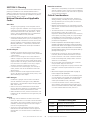 3
3
-
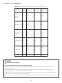 4
4
-
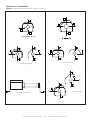 5
5
-
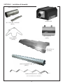 6
6
-
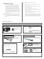 7
7
-
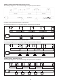 8
8
-
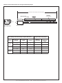 9
9
-
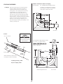 10
10
-
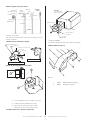 11
11
-
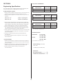 12
12
-
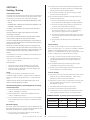 13
13
-
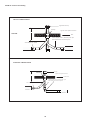 14
14
-
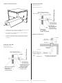 15
15
-
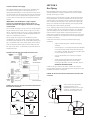 16
16
-
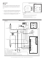 17
17
-
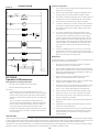 18
18
-
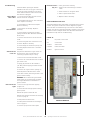 19
19
-
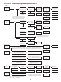 20
20
-
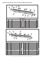 21
21
-
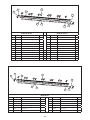 22
22
-
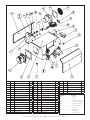 23
23
-
 24
24
-
 25
25
-
 26
26
-
 27
27
-
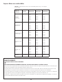 28
28
-
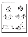 29
29
-
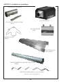 30
30
-
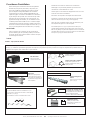 31
31
-
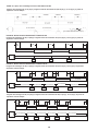 32
32
-
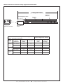 33
33
-
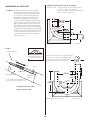 34
34
-
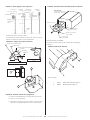 35
35
-
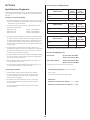 36
36
-
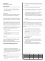 37
37
-
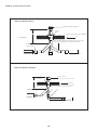 38
38
-
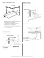 39
39
-
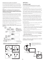 40
40
-
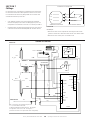 41
41
-
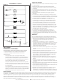 42
42
-
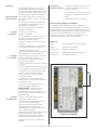 43
43
-
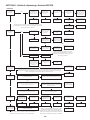 44
44
-
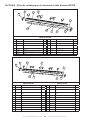 45
45
-
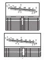 46
46
-
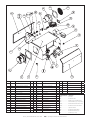 47
47
-
 48
48
-
 49
49
-
 50
50
-
 51
51
-
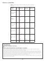 52
52
-
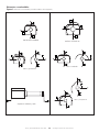 53
53
-
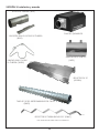 54
54
-
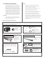 55
55
-
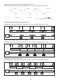 56
56
-
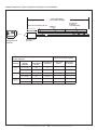 57
57
-
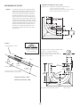 58
58
-
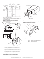 59
59
-
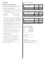 60
60
-
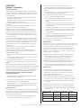 61
61
-
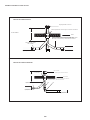 62
62
-
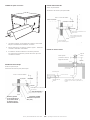 63
63
-
 64
64
-
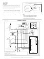 65
65
-
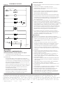 66
66
-
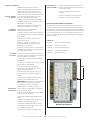 67
67
-
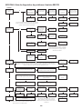 68
68
-
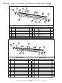 69
69
-
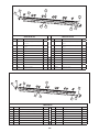 70
70
-
 71
71
-
 72
72


HeatStar ER2STG100-LP El manual del propietario
- Categoría
- Calentadores espaciales
- Tipo
- El manual del propietario
- Este manual también es adecuado para
en otros idiomas
Artículos relacionados
-
HeatStar ER2STG125-LP El manual del propietario
-
-
HeatStar HSU80NG El manual del propietario
-
-
-
-
-
-
-