La página se está cargando...

225 Wilshire Ave SW, Concord NC, 28025 Phone: 800-230-0319 Email: info@safewaze.com Web: safewaze.com Fax: 704-262-9051
II I I I
018-4001
Beam Trolley
Instruction Manual
OSHA 1926 Subpart M, OSHA 1910, ANSI Z359.1, and ANSI A10.32
This manual is intended to meet the manufacturer’s instructions as required by
ANSI Z359 and should be used as part of an employee training program as required
by OSHA.
WARNING
This product is part of a personal fall arrest, work positioning, suspension or rescue system. The
manufacturer’s instructions must be provided to users of this equipment. The user must follow the
manufacturer’s instructions for each component of the system. The user must read and understand these
instructions before using this equipment. Manufacturer’s instructions must be followed for proper use
and maintenance of this equipment. Alterations to this product, misuse of this product, or failure to follow
instructions may result in serious injury or death.
IMPORTANT
Questions regarding the use, care, or suitability of this equipment for your application? Contact
Safewaze.
IMPORTANT
Record identication information before using this product. Identication information may be found on
the equipment label. This information should be recorded in the “Inspection Log” located at the back of
this manual
Do not throw away these instructions!
Read and understand these instructions before using equipment!
User Information
Date of First Use:
Serial#:
Trainer:
User:
INTRODUCTION
Thank you for purchasing the Safewaze 018-4001 Beam Trolley anchor. This manual must be read and
understood in its entirety, and used as part of an employee training program as required by OSHA or any
applicable state agency. This manual and any other instructional material must be available to the user
of the equipment. The user must understand how to safely and eectively use the 018-4001 Beam Trol-
ley Anchor, and all fall protection equipment used in conjuction with the Beam Trolley Anchor.
APPLICABLE SAFETY STANDARDS
When used according to instructions, the 018-4001 Beam Trolley meets all applicable ANSI Z359.1
standards and OSHA regulations for fall protection. Applicable standards and regulations depend on the
type of work being done, and may include state-specic regulations. Refer to local, state, and federal
(OSHA) requirements for additional information concerning the governing of occupational safety
regarding Personal Fall Arrest Systems (PFAS).
WORKER CLASSIFICATIONS
Understand the denitions of those who work in proximity of or may be
exposed to fall hazards.
Qualied Person: “Qualied” means one who, by possession of a recognized degree, certicate,
or professional standing, or who by extensive knowledge, training, and experience, has successfully
demonstrated his ability to solve or resolve problems relating to the subject matter, the work, or the
project.
Competent Person: “Competent person” means one who is capable of identifying existing and predict-
able hazards in the surroundings or working conditions which are unsanitary, hazardous, or dangerous to
employees, and who has authorization to take prompt corrective measures to eliminate them.
Authorized Person: “Authorized person” means a person approved or assigned by the employer to
perform a specic type of duty or duties or to be at a specic location or locations at the job site.
It is the responsibility of a Qualied or Competent person to supervise the job site and
ensure safety regulations are complied with.
PRODUCT SPECIFIC APPLICATIONS
Purpose: The Safewaze 018-4001 Beam Trolley is designed to be used as part of a Personal Fall
Arrest System (PFAS).
- A competent person shall train users on this equipment in accordance with OSHA
and ANSI.
- Never exceed a free fall distance of 6 ft. A free fall of more than 6 ft could cause
excessive arrest forces that could result in serious injury or death.
- The Safewaze 018-4001 Beam Trolley has a maximum capacity of 310 lbs
including any tools, clothing, accessories, etc..., unless otherwise rated by
Safewaze.
- Structures for attachment of Safewaze 018-4001 beam Trolley shall support a
minimum 5,000 lbs or be designed with a safety factor of two by a Qualied Person.
- All Safewaze anchors must IMMEDIATELY be removed from service if subjected
to fall arrest forces.
- Safewaze anchors shall be inspected by the end user prior to each usage and
by a Competent Person other than the user every 6 months. These inspections shall
be documented.
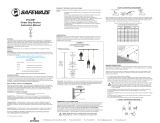
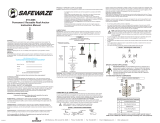
Lanyard Length
(6’ Total)
Deceleration
distance (3.5’ total)
Height of harness dorsal
D-ring from
worker’s feet
(6’ total)
Safety factor
(2’ total)
Required
distance
from
Anchorage
(17.5’ total)
Fall Clearance: There must be sucient clearance below the anchorage connector to arrest a fall
before the user strikes the ground or an obstruction. When calculating fall clearance, account for a
MINIMUM 2’ safety factor, deceleration distance, user height, length of lanyard/SRL, and all other
applicable factors. (See Figure 1)
LIMITATIONS
Fall Clearance Diagram
***Diagram shown is an example
fall clearance calculation ONLY.
For all applications: worker weight capacity range
(including all clothing, tools, and equipment) is 130-310 lbs
FIGURE 1
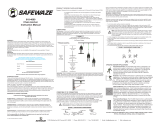
Swing Falls: Prior to installation or use, make considerations for eliminating or minimizing all swing
fall hazards. Swing falls occur when the anchor is not directly above the location where a fall occurs.
Always work as close to in line with the anchor point as possible. Swing falls signicantly increase
the likelihood of serious injury or death in the even of a fall. (See Figure 2)
A
FALL-ARREST
S
W
I
N
G
F
A
L
L
COMPATIBILITY OF CONNECTORS
Connectors are compatible with connecting elements when they have been designed to work together
in such a way that their sizes and shapes do not cause their gate mechanisms to inadvertently open
regardless of how they become oriented. Connectors (hooks, carabiners, and D-rings) must be
capable of supporting at least 5,000 lbs. (22.2 kN). Connectors must be compatible with the anchorage
or other system components (see Figure 4). Do not use equipment that is not compatible. Non-
compatible connectors may unintentionally disengage (see Figure 3). Connectors must be compatible
in size, shape, and strength. Self-locking snap hooks and carabiners are required by ANSI Z359 and
OSHA guidelines. Contact Safewaze if you have any questions about compatibility.
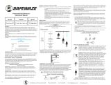
FIGURE 3 - UNINTENTIONAL DISENGAGEMENT
3 - Gate opens
2 - Gate presses
against
non-compliant
part
4 - And parts
disengage.
1 - Non Compliant Part
NOTE: SOME SPECIALITY CONNECTORS HAVE ADDITIONAL
REQUIREMENTS. CONTACT Safewaze WITH QUESTIONS.
FIGURE 2
FIGURE 4 - INAPPROPRIATE CONNECTIONS
MAKING CONNECTIONS
Snap hooks and carabiners used with this equipment must be double locking and/or twist lock. Ensure
all connections are compatible in size, shape and strength. Do not use equipment that is not compatible.
Ensure all connectors are fully closed and locked.
Safewaze connectors (snap hooks and carabiners) are designed to be used only as specied in each
product’s user’s instructions. See gure 4 for examples of inappropriate connections. Do not connect
snap hooks and carabiners:
• To a D-ring to which another connector is attached.
• In a manner that would result in a load on the gate (with the exception of tie back hooks). NOTE:
Large snap hooks must not be connected to objects which will result in a load on the gate if the hook
twists or rotates. Snap hooks marked with ANSI Z359.12 and are equipped with a 3,600 lb (16 kN)
gate. Check the marking on your snap hook to verify its compatibility.
NOTE: Large throat snap hooks must not be connected to standard size D-rings or similar
objects which will result in a load on the gate if the hook or D-ring twists or rotates, unless
the snap hook complies with ANSI Z359.1-2007 or ANSI Z359.12 and is equipped with a
3,600 lb (16 kN) gate. Check the marking on your snap hook to verify that it is appropriate
for your application.
• In a false engagement, where features that protrude from the snap hook or carabiner catch on the
anchor, and without visual conrmation seems to be fully engaged to the anchor point.
• To each other.
• By wrapping the web lifeline around an anchor and securing to lifeline except as allowed for Tie Back
models.
• To any object which is shaped or sized in a way that the snap hook or carabiner will not close and
lock, or that roll-out could occur.
• In a manner that does not allow the connector to align properly while under load.
Using a connector that is undersized or irregular in shape (1) to connect a snap hook or carabiner could
allow the connector to force open the gate of the snap hook or carabiner. When force is applied, the gate
of the hook or carabiner presses against the non-compliant part (2) and forces open the gate (3). This
allows the snap hook or carabiner to disengage (4) from the connection point.
2027
SPECIFIC ANCHOR APPLICATIONS
Personal Fall Arrest: The 018-4001 Beam Trolley is designed as an
anchor point to support a maximum of 1 Personal Fall Arrest System
(PFAS) when utilized for fall protection applications. The structure to
which the anchor is attached must withstand loads applied in the
directions permitted by the system of at least 5,000 lbs. Maximum
allowable free fall is 6’.
Restraint: The 018-4001 Beam Trolley is authorized for use in Restraint
applications. The structure to which the anchor is attached must withstand
loads applied in the directions permitted by the system of at least 1,000
lbs NO free fall is permitted. Restraint systems may only be used on
surfaces with slopes up to 4 / 12 (vertical / horizontal). For Restraint
applications, the allowable attachment points to harness are Dorsal
D-ring, Chest D-ring, Side D-rings, and Shoulder D-rings.
Work Positioning: The 018-4001 Beam Trolley is authorized for use in
Work Positioning applications. Work Positioning allows a worker to be
supported during suspension while freeing both hands to conduct work
operations. The structure to which the Beam Trolley is attached must
withstand loads applied in the directions permitted by the system of at
least 3,000 lbs. Maximum allowable free fall is 2’. For positioning
applications, the allowable attachment points to harness are the Side
D-rings.
Rescue/Conned Space: The 018-4001 Beam Trolley is authorized for
use in Rescue/Conned Space applications. Rescue systems are utilized
to safely recover a worker from a conned location or after exposure to
a fall. Composition of rescue systems can vary based upon the type of
rescue involved. The structure to which a Beam Trolley is attached must
withstand loads applied in the directions permitted by the system of at
least 3,000 lbs. NO free fall is permitted. For rescue applications, the
allowable attachment points to harness are Dorsal D-ring, Chest D-ring
and Shoulder D-rings.
All above referenced applications have a worker weight capacity range of 310 lbs
(including all clothing, tools, and equipment).

225 Wilshire Ave SW, Concord NC, 28025 Phone: 800-230-0319 Email: info@safewaze.com Web: safewaze.com Fax: 704-262-9051
II I I I
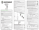
INSTALLATION
INSTALLATION EXAMPLE018-4001 BEAM TROLLEY COMPONENTS
WARNING
• Users should consult with their doctor to verify ability to safely absorb the forces of a
fall arrest event. Fitness level, age, and other health conditions can greatly aect an
individuals ability to withstand fall arrest forces. Women who are pregnant, individuals
considered minors must not use any Safewaze equipment.
• Never alter any part of a lanyard or add/remove components. Safewaze shall not be
held responsible for injury or death due to tampering.
• Anchors that are exposed to fall arrest forces MUST be IMMEDIATELY removed
from service and destroyed.
• Failure to follow these instructions and warnings could result in serious injury or
death in the event of a fall.
• A preplanned rescue procedure in the event of a fall is required. The rescue plan
must be specic to the project. The rescue plan must allow for employees to rescue
themselves, or to be promptly rescued by alternative means.
• Harnesses or connectors selected for use with any Safewaze anchor must be
compatible in size and conguration. User must ensure compatibility of snap hooks,
carabiners and other connectors. Any connection which could allow disengagement
must be eliminated. Snap hooks and carabiners must be self locking and self closing
and must never be hooked to each other.
• A Competent Person must conduct an analysis of the workplace and anticipate
where workers will be conducting their duties, the route they will take to reach their
work, and the existing and potential fall hazards they may be exposed to. The
Competent Person must choose the fall protection equipment to be utilized.
• Do not misuse equipment.
• Equipment designated for fall protection must never be used to lift, hang, support or
hoist tools or equipment unless specically certied for such use.
• Safewaze Anchors shall be inspected prior to each use by the user and at least every
6 months by a Competent Person. Annual inspections shall be documented. Severity
of conditions during use may neccesitate increased frequency of documented
inspections.
• Anchors that fail inspection MUST be removed from service.
• Prior to each use, inspect the 018-4001 Beam Trolley for deciencies or damage,
including, but not limited to, sharp edges, rough edges, deformations, corrosion, pits,
burrs, chemical exposure, extreme heat exposure, or missing or illegible labels. If any
deciencies or defects are found, the 018-4001 must IMMEDIATELY be removed from
service.
• The 018-4001 Beam Trolley must be inspected at least every 6 months by a
Competent Person other than the user. Competent person inspections must be
recorded in the inspection log included in this manual and on the inspection grid label
on the 018-4001.
INSPECTION
MAINTENANCE & STORAGE
WARRANTY
The 018-4001 Beam Trolley can be cleaned with water and mild soap if necessary.
User should remove all dirt, possible corrosives, and contaminants from the anchor
prior to, and after each use. Never use any type of corrosive substance to clean the
018-4001.
Excess water should be blown out with compressed air. Hardware can be wiped o
with a clean, dry cloth.
When not in use, store the 018-4001 Beam Trolley in a cool dry area where it will not
be exposed to extreme light, extreme heat, excessive moisture, or possibly corrosive
chemicals or materials.
Safewaze warrants its products are free from defects in materials and
construction under normal use and service. Liability is not accepted for abuse,
modication, improper use, destructive activity and contaminated exposure.
INSPECTION LOG
Date Inspection Items
Noted
Corrective Action Initials
LABELS
Safewaze
225 Wilshire Ave SW
Concord, NC 28025
PHONE: 800-230-0319
FAX: 704-262-9051
EMAIL: info@safewaze.com
Web: safewaze.com
1. Under guidance of a Competent Person, a suitable anchor point must be chosen that
meets the strength requirement, minimizes free fall, and reduces swing fall hazards. Do
not work above the anchorage point.
2. The 018-4001 Beam Trolley can be installed on any beam that meets the strength
requirements as dened in the SPECIFIC ANCHOR APPLICATIONS section of this
manual for Personal Fall Arrest.
3. The beam to which the 018-4001 Beam Trolley is attached must be closed at both
ends to ensure the Beam Trolley is not capable of rolling o either end. Pre-installed
welded or bolted stops, at each end of the beam, provide the most secure safety stops
for the Beam Trolley.
4. The beam must be inspected prior to installation for any defect including, but not
limited to, deformities, cracks, severe corrosion, excessive paint, welding spatter or
slag, icing, loose beam fasteners, or any excessive debris or condition that would
potentially impede the movement of the 018-4001 Beam Trolley wheels along the
surface of the beam.
5. The 018-4001- Beam Trolley is designed for use on I-Beams 3.5” to 14” wide with a
maximum ange thickness of 1-3/4”. Depress the spring loaded width adjustment lever
on the adjustable wheeled side plate and slide the side plates apart so the wheels clear
the ange. Fit the Beam Trolley over the beam ange and slide the adjustable wheeled
side plate towards the xed side until there is approximately 1/2” between the ange
edge and the rub pad on the inside of the adjustable wheel. Ensure all wheels are
resting on the ange. Make sure the width adjustment lever on the adjustable wheeled
side plate is engaged with the notched adjustment bar by releasing the width
adjustment lever, and pulling out slightly on the adjustable wheel side plate to ensure it
is locked into place. For example of installation, see Figure 6.
6. Connect the PFAS connector to the Beam Trolley and ensure proper Beam Trolley
attachment and function by exerting a sharp tug. The Beam Trolley should smoothly
track along the beam with the users movements.
7. User should work directly under the 018-4001 Beam Trolley at all times, and ensure
that the load direction placed on the 018-4001 does not exceed 30 degrees from the
vertical in any direction.
Part# 018-4001
Beam Trolley
Min. Break Strength: 5,000 lbs
Materials: Aluminum, Stainless Steel, Ertalon® nylon wheels
Capacity: 130-310 lbs including clothing, tools, etc.
OSHA 1926.502 ANSI Z359.1
Manufacture Date: XX/XX
Serial #: XXXXXXX
800-230-0319
DO NOT REMOVE LABEL
J DNOSAJJMAMF
WARNING
! THIS EQUIPMENT IS DESIGNED FOR USE AS A FALL
PROTECTION ANCHOR. USER MUST READ AND FOLLOW INSTRUCTIONS
SUPPLIED WITH THIS PRODUCT AT TIME OF SHIPMENT. FAILURE TO DO SO
MAY RESULT IN SERIOUS INJURY OR DEATH. AVOID CONTACT WITH
HAZARDS INCLUDING BUT NOT LIMITED TO, HEAT, CHEMICALS,
ELECTRICITY, AND SHARP OR ABRASIVE EDGES AND SURFACES. MAKE
ONLY COMPATIBLE CONNECTIONS. REFER TO INSTRUCTIONS FOR
APPROPRIATE INSTALLATION AND CONNECTION METHODS.
USER MUST INSPECT BEFORE EACH USE. COMPETENT PERSON
MUST INSPECT AT LEAST ONCE EVERY 6 MONTHS AND PUNCH
CORRESPONDING MONTH/YEAR ON INSPECTION GRID.
IF UNIT FAILS INSPECTION
REMOVE FROM SERVICE
1118 a
AB
C
D
E
F
Trolley Crossbar
B
C
D
E
F
Label Ring
Width Adjustment Lever
Adjustable Wheel Side Plate
Ertalon® Nylon Wheels
Steel Ring Assembly Attachment Point
018-4001 Beam Trolley Components
A
30° 30°
Proper Load Direction
FIGURE 5 - BEAM TROLLEY COMPONENTS
FIGURE 6 - INSTALLATION

| 225 Wilshire Ave SW, Concord NC, 28025 | Teléfono: 800-230-0319 | Fax: 704-262-9051 | Correo electrónico: info@safewaze.com | Web: safewaze.com
ADVERTENCIA
Este producto forma parte de un sistema personal de parada de caídas, posicionamiento de trabajo, suspensión o rescate. Las
instrucciones del fabricante se le deben entregar al usuario de este equipo. El usuario debe seguir las instrucciones del fabricante de cada
componente del sistema. Antes de usar este equipo, el usuario debe leer y entender estas instrucciones. El usuario debe seguir las
instrucciones del fabricante para usar y mantener correctamente este equipo. Alterar o usar incorrectamente este producto, o no seguir las
instrucciones, puede causar lesiones graves o muerte.
IMPORTANTE
Si tiene dudas sobre el uso, cuidado o idoneidad de este equipo para sus propósitos, comuníquese con Safewaze.
IMPORTANTE
Registre los datos de identificación antes de usar este producto. Los datos de identificación se encuentran en la etiqueta del equipo. Estos
datos deben anotarse en el registro de inspecciones al final de este manual.
OSHA 1926, Subparte M; OSHA 1910, ANSI Z359.1 y ANSI A10.32
El objetivo de este manual es presentar las instrucciones del fabricante conforme a la norma
ANSI Z359. Este manual debe formar parte de un programa de capacitación de empleados
conforme a la Ley de Salud y Seguridad Ocupacional (Occupational Safety and Health Act, OSHA).
Datos del usuario
Fecha de la primera vez que usó el equipo:
Nro. de serie:
Capacitador:
Usuario:
¡No deseche estas instrucciones!
Antes de usar este equipo, el usuario debe leer y entender estas instrucciones.
INTRODUCCIÓN
Gracias por comprar el carro de viga 018-4001 de Safewaze. El usuario debe leer y entender todo este manual, que debe formar parte de
un programa de capacitación del usuario según lo requerido por la OSHA o las agencias estatales correspondientes. Este manual y todo
otro material de enseñanza deben estar siempre a disposición del usuario del equipo. El usuario debe entender cómo usar segura y
efectivamente el carro de viga 018-4001 y todo el equipo de protección contra caídas que se use con el carro de viga.
NORMAS DE SEGURIDAD APLICABLES
Cuando se usa conforme a las instrucciones, el carro de viga 018-4001 cumple con la norma ANSI Z359.1 y los reglamentos de la OSHA
aplicables relacionados con la protección contra caídas. Las normas y los reglamentos aplicables dependen del tipo de trabajo y pueden
incluir reglamentos estatales específicos. Consulte los requisitos locales, estatales y federales (OSHA) para ver más información sobre los
reglamentos de seguridad ocupacional que rigen los sistemas personales de parada de caídas.
DENOMINACIONES DE USUARIOS
Entienda las denominaciones de las personas que se exponen a caídas o trabajan
cerca de estructuras que implican riesgo de caída.
Persona calificada: Persona que por título, certificado o prestigio profesional reconocido, o por amplio conocimiento, capacitación y
experiencia, ha demostrado su capacidad de resolver problemas relacionados con el tema, el trabajo o el proyecto.
Persona competente: Persona capaz de detectar peligros ambientales presentes y predecibles o condiciones de trabajo insalubres o
peligrosas para los empleados. Esta persona está autorizada para tomar medidas correctivas inmediatas a fin de eliminar tales peligros y
condiciones.
Persona autorizada: Persona aprobada o nombrada por el empleador para hacer tareas específicas o estar presente en lugares
específicos de la obra.
Las personas calificadas o competentes son responsables de supervisar el lugar de trabajo y garantizar que se cumplan las
normas de seguridad.
CONFIGURACIONES ESPECÍFICAS DEL PRODUCTO
Propósito: El carro de viga 018-4001 de Safewaze forma parte de un Sistema Personal de Parada de Caídas (Personal Fall Arrest
System, PFAS).
- Una persona competente debe capacitar a los usuarios de este equipo conforme a las normas de la OSHA y el ANSI.
- No exceda nunca 6 pies de caída libre. Las caídas libres de más de 6 pies ejercen fuerzas de parada excesivas que pueden
causar lesiones graves o muerte.
- El carro de viga 018-4001 de Safewaze tiene una capacidad máxima de 310 libras, incluyendo herramientas, ropa, accesorios,
etc., a menos que Safewaze determine otra cosa.
- Las estructuras a las cuales se fije el carro de viga 018-4001 de Safewaze deben soportar un mínimo de 5,000 lbs. o haber sido
diseñadas con un factor de seguridad de dos por una persona calificada.
- Todas las anclas de Safewaze deben ponerse fuera de servicio INMEDIATAMENTE si se someten a fuerzas de parada de caída.
- Las anclas de Safewaze deben ser inspeccionadas por el usuario final cada vez que las va a usar y por una persona competente
que no sea el usuario cada 6 meses. Estas inspecciones se deben documentar.
LIMITACIONES
Altura de caída: Debe haber suficiente espacio debajo del conector de anclaje para parar una caída antes de que el usuario llegue al
suelo o se golpee contra una obstrucción. Cuando calcule la altura de caída, considere la distancia de desaceleración, la estatura del
usuario, la longitud del cordón o la SRL, un factor de seguridad de 2 pies como MÍNIMO, y todo otro factor aplicable (Figura 1).
Caídas pendulares: Antes de instalar o usar el sistema, elimine o minimice los riesgos de caídas pendulares, que se producen cuando el
punto de anclaje no está directamente encima del punto de caída. Trabaje siempre lo más cerca posible del punto de anclaje. Las caídas
pendulares aumentan significativamente la probabilidad de lesiones graves o muerte en caso de caída (Figura 2).
FIGURA 2
COMPATIBILIDAD DE CONECTORES
Los conectores son compatibles con los elementos que se les conectan cuando han sido diseñados para funcionar juntos de manera que
su tamaño y su forma no causen la apertura imprevista de los mecanismos de los cierres, independientemente de su orientación. Los
conectores (ganchos, mosquetones y anillos en D) deben tener al menos 5,000 lbs. (22.2 kN) de capacidad. Los conectores deben ser
compatibles con el anclaje y los otros componentes del sistema (Figura 4). No use equipo incompatible. Los conectores incompatibles
pueden desengancharse de improviso (Figura 3). Los conectores deben ser compatibles en cuanto a tamaño, forma y capacidad. La norma
ANSI Z359 y las directrices de la OSHA exigen ganchos de presión y mosquetones de bloqueo automático. Comuníquese con Safewaze si
tiene preguntas sobre compatibilidad.
NOTA: ALGUNOS CONECTORES ESPECIALIZADOS TIENEN REQUISITOS
ADICIONALES. COMUNÍQUESE CON SAFEWAZE SI TIENE PREGUNTAS.
FIGURA 3 - DESENGANCHE NO INTENCIONAL
Conectar un conector demasiado pequeño o de forma irregular (1) a un mosquetón o un gancho de presión puede permitir que el conector
abra el cierre del mosquetón o gancho de presión. Cuando se ejerce fuerza, el cierre del mosquetón o del gancho presiona la pieza
incompatible (2) y se abre (3). Esto permite que el mosquetón o gancho de presión se desenganche (4).
FORMACIÓN DE CONEXIONES
Los mosquetones y ganchos de presión de este equipo deben tener cierre de bloqueo doble y/o cierre giratorio. Todas las conexiones
deben ser compatibles en cuanto a tamaño, forma y capacidad. No use equipo incompatible. Todos los conectores deben estar
completamente cerrados y bloqueados.
Los conectores de Safewaze (mosquetones y ganchos de presión) deben usarse solo como se especifica en las instrucciones de cada
producto. En la Figura 4 hay ejemplos de conexiones incorrectas. No conecte mosquetones o ganchos de presión…
A un anillo en D al cual ya esté conectado otro conector.
De una manera que ejerza fuerza sobre el cierre (excepto en caso de ganchos de sujeción) NOTA: No se deben conectar ganchos de
presión grandes a objetos que se apoyarían en el cierre si el gancho se torciera o girara, a menos que el gancho de presión cumpla con
la norma ANSI Z359.12 y tenga un cierre de 3,600 lbs. (16 kN) de capacidad. Vea el marcado del gancho de presión para verificar su
compatibilidad.
NOTA: Los ganchos de presión de gran apertura no se deben conectar a anillos en D de tamaño estándar u objetos
similares que se apoyarían en el cierre si el gancho o el anillo en D se torciera o girara, a menos que el gancho de
presión cumpla con la norma ANSI Z359.1-2007 o ANSI Z359.12 y tenga un cierre de 3,600 lbs. (16 kN) de
capacidad. Vea el marcado del gancho de presión para verificar su compatibilidad.
Con enganche falso, que se produce cuando las partes sobresalientes del mosquetón o gancho de presión se enganchan en el anillo de
conexión del carro de viga y, sin confirmación visual, dan la impresión de que el mosquetón o gancho de presión está bien enganchado
en el anclaje
Uno a otro
Pasando la línea salvavidas de correa tejida alrededor del anclaje y fijándola a la misma línea salvavidas, excepto según lo permitido en
los modelos de sujeción
A objetos cuya forma o tamaño pueda causar una desconexión o impedir que el mosquetón o gancho de presión se cierre y se bloquee
De una manera que impida la alineación correcta del conector cargado.
CONFIGURACIONES ESPECÍFICAS DEL CARRO DE VIGA
Parada de caída personal: El carro de viga 018-4001 es un dispositivo de anclaje que soporta un máximo de un
(1) Sistema Personal de Parada de Caídas (Personal Fall Arrest System, PFAS) en configuraciones de
protección contra caídas. La estructura a la cual se fije el carro de viga debe soportar cargas de al menos
5,000 lbs. aplicadas en las direcciones permitidas por el sistema. La caída libre máxima permitida es de 6 pies.
Restricción: El carro de viga 018-4001 se puede usar en configuraciones de restricción. La estructura a la cual
se fije el carro de viga debe soportar cargas de al menos 1,000 lbs. aplicadas en las direcciones permitidas por el
sistema. NO se permite la caída libre. Los sistemas de restricción se pueden usar solo en superficies con
pendientes de hasta 4 / 12 (vertical / horizontal). En configuraciones de restricción, los puntos de fijación
permitidos del arnés son el anillo dorsal en D, el anillo pectoral en D, los anillos laterales en D y los anillos en D
de los hombros.
Posicionamiento de trabajo: El carro de viga 018-4001 se puede usar en configuraciones de posicionamiento
de trabajo, en las cuales el usuario es sostenido para que pueda trabajar con las dos manos. La estructura a la
cual se fije el carro de viga debe soportar cargas de al menos 3,000 lbs. aplicadas en las direcciones permitidas
por el sistema. La caída libre máxima permitida es de 2 pies. En configuraciones de posicionamiento, los puntos
de fijación permitidos del arnés son los anillos laterales en D.
Rescate y espacio reducido: El carro de viga 018-4001 se puede usar en configuraciones de rescate y espacio
reducido. Los sistemas de rescate permiten recuperar con seguridad a un usuario atrapado en un espacio
reducido o suspendido en el aire después de una caída. La composición del sistema de rescate depende del tipo
de rescate. La estructura a la cual se fije el carro de viga debe soportar cargas de al menos 3,000 lbs. aplicadas
en las direcciones permitidas por el sistema. NO se permite la caída libre. En configuraciones de rescate, los
puntos de fijación permitidos del arnés son el anillo dorsal en D, el anillo pectoral en D y los anillos en D de los
hombros.
En todas las configuraciones consideradas, el intervalo de capacidad de este equipo es de
130 a 310 lbs. por usuario (incluyendo herramientas, ropa y equipo).
2027
FIGURA 4 - CONEXIONES INCORRECTAS
018-4001
Manual de instrucciones
de carro de viga
1 - Pieza incompatible
2 - El cierre
presiona la
pieza
incompatible.
3 - El cierre se abre.
4 - Las piezas se desenganchan.
FIGURA 1
En todas las configuraciones, el intervalo de capacidad de este equipo es de
130 a 310 lbs. por usuario (incluyendo herramientas, ropa y equipo).
Diagrama de altura de caída
*** El diagrama que se muestra es SOLO un
ejemplo de cálculo de altura de caída.
Longitud del cordón
(6 pies)
Distancia requerida
desde el anclaje
(17.5 pies en total)
Distancia de desaceleración
(3.5 pies)
Factor de seguridad
(2 pies)
Altura del anillo dorsal en D
del arnés desde los pies del
usuario (6 pies)

| 225 Wilshire Ave SW, Concord NC, 28025 | Teléfono: 800-230-0319 | Fax: 704-262-9051 | Correo electrónico: info@safewaze.com | Web: safewaze.com
018-4001 COMPONENTES DEL CARRO DE VIGA 018-4001
Componentes del carro de viga 018-4001
A
Anillo de etiqueta
B
Palanca de ajuste de ancho
C
Placa lateral de rueda ajustable
D
Ruedas de nylon Ertalon®
E
Anillo de acero: punto de fijación del carro
F
Barra transversal del carro
INSTALACIÓN
1. Con la asesoría de una persona competente o calificada, establezca un anclaje apropiado que cumpla con los
requisitos de resistencia, minimice la caída libre y reduzca el riesgo de caída pendular. No trabaje más arriba
del punto de anclaje.
2. El carro de viga 018-4001 se puede instalar en cualquier viga que cumpla con los requisitos de resistencia
definidos en la sección CONFIGURACIONES ESPECÍFICAS DEL CARRO DE VIGA de este manual de parada
de caída personal.
3. La viga por la cual se desplaza el carro de viga 018-4001 se debe cerrar en los dos extremos para evitar que el
carro se salga de la viga. Los mejores topes de seguridad son los topes soldados o atornillados de fábrica en
los extremos de la viga.
4. Antes de instalar el carro de viga 018-4001, la viga se debe inspeccionar para detectar los defectos que pueda
tener, tales como, entre otros, deformaciones, grietas, exceso de corrosión, exceso de pintura, salpicaduras de
soldadura o escoria, hielo, fijadores de viga sueltos, exceso de residuos, o condiciones que puedan impedir el
movimiento de las ruedas del carro por la viga.
5. El carro de viga 018-4001 es para vigas en I con bridas de 3-1/2 a 14 plg. de ancho y grosor máximo de
1-3/4 plg. Presione la palanca de ajuste de ancho con resorte de la placa lateral ajustable con ruedas. Aparte la
placa lateral para pasar las ruedas alrededor de la brida. Ponga el carro de viga sobre la brida y empuje la
placa lateral ajustable con ruedas hacia la placa lateral fija hasta que haya aproximadamente 1/2 plg. entre el
borde de la brida y la almohadilla de fricción del lado interno de la rueda ajustable. Todas las ruedas deben
quedar apoyadas en la brida. Asegúrese de que la palanca de ajuste de ancho de la placa lateral ajustable con
ruedas esté enganchada en la barra de ajuste con muescas soltando la palanca de ajuste de ancho y jalando
ligeramente la placa lateral de la rueda ajustable. En la Figura 6, se muestra un ejemplo de instalación.
6. Conecte el conector del PFAS al carro de viga. Asegúrese de que el carro de viga funcione y esté bien
conectado jalando bruscamente el PFAS. El carro de viga debe desplazarse uniformemente por la viga
siguiendo los movimientos del usuario.
7. El usuario debe trabajar directamente debajo del carro de viga 018-4001 en todo momento y asegurarse de que
la dirección de la carga del 018-4001 no se desvíe más de 30° de la vertical en ninguna dirección.
EJEMPLO DE INSTALACIÓN
ADVERTENCIA
El usuario debe consultar al médico para verificar su capacidad de absorber con seguridad el impacto de una
parada de caída. La edad, el estado físico y otras condiciones de salud afectan seriamente la capacidad de
soportar fuerzas de caída. Ni los menores de edad ni las mujeres embarazadas deben usar ningún equipo de
Safewaze.
Nunca altere ninguna parte de un cordón ni agregue ni quite componentes. Safewaze no se responsabiliza por
lesiones o muerte causadas por alteraciones o cambios del equipo.
Los carros de viga expuestos a fuerzas de parada de caída DEBEN destruirse o ponerse fuera de servicio
INMEDIATAMENTE.
No respetar estas instrucciones y advertencias puede causar lesiones graves o muerte en caso de caída.
Se requiere un plan de rescate de caída establecido de antemano. El plan de rescate debe corresponder al
proyecto. El plan de rescate debe permitir que los empleados se rescaten a sí mismos o que sean rescatados
rápidamente por otros medios.
Los arneses o conectores de Safewaze que se van a usar con el carro de viga deben ser compatibles en
cuanto a tamaño y configuración. El usuario debe asegurarse de la compatibilidad de los mosquetones,
ganchos de presión y otros conectores. Toda conexión que permita desconexión debe ser eliminada. Los
mosquetones y ganchos de presión deben ser de bloqueo y cierre automático y no deben engancharse nunca
entre sí.
Una persona competente debe analizar el área de trabajo y anticipar los lugares en que los usuarios llevarán a
cabo sus tareas, la ruta que seguirán para llegar a su lugar de trabajo y los riesgos de caída presentes y
posibles a los que se pueden exponer. La persona competente debe escoger el equipo de protección contra
caídas que se utilizará.
No use mal el equipo.
El equipo destinado a protección contra caídas no debe usarse nunca para levantar, colgar, soportar o izar
herramientas o equipo, a menos que haya sido específicamente certificado para eso.
INSPECCIÓN
Los carros de viga de Safewaze deben ser inspeccionados cada vez por el usuario que los va a usar y por una
persona competente cada 6 meses. Las inspecciones anuales se deben documentar. La intensidad de las
condiciones de uso puede requerir una mayor frecuencia de inspecciones documentadas.
Los carros de viga que no pasen la inspección se DEBEN poner fuera de servicio.
Cada vez que vaya a usar el carro de viga 018-4001, inspecciónelo para ver si tiene deficiencias o daños tales
como, entre otros, bordes afilados o ásperos, deformaciones, corrosión, picaduras, rebabas, señales de
exposición a productos químicos o calores extremos, o etiquetas perdidas o ilegibles. Si se encuentran
deficiencias o defectos, el 018-4001 debe ponerse INMEDIATAMENTE fuera de servicio.
Una persona competente que no sea el usuario debe inspeccionar el carro de viga 018-4001 al menos una vez
cada 6 meses. Las inspecciones llevadas a cabo por la persona competente se deben anotar en el registro de
inspecciones de este manual y en la cuadrícula de la etiqueta de inspección del 018-4001.
GARANTÍA
Safewaze garantiza que sus productos carecen de defectos de materiales o mano de obra y que funcionan correctamente en condiciones
normales de uso y servicio. Safewaze no acepta responsabilidad por abuso, modificación, uso indebido, actividad destructiva o
contaminación.
MANTENIMIENTO Y ALMACENAMIENTO
El carro de viga 018-4001 se puede lavar con agua y jabón suave si es necesario. El usuario debe quitarle la suciedad, los contaminantes y
las sustancias posiblemente corrosivas cada vez antes y después de usarlo. No limpie nunca el 018-4001 con ningún tipo de sustancia
corrosiva.
El exceso de agua se debe retirar con aire comprimido. Los herrajes se pueden limpiar con un paño limpio y seco.
Cuando no lo esté usando, guarde el carro de viga 018-4001 en un lugar fresco y seco donde no quede expuesto a cantidades extremas
de luz, calor o humedad, o a materiales o productos químicos posiblemente corrosivos.
ETIQUETAS
1118a
Fecha de fabricación: XX/XX
Nro. de serie: XXXXXXX
800-230-0319
Pieza Nro. 018-4001
Carro de viga
Resistencia mínima a la rotura: 5,000 lbs.
Materiales: aluminio, acero inoxidable, ruedas de
nylon Ertalon®
Capacidad: 130 a 310 lbs. incluyendo ropa,
herramientas, etc.
OSHA 1926.502 ANSI Z359.1
¡ADVERTENCIA! ESTE EQUIPO ES UN DISPOSITIVO DE
ANCLAJE DE PROTECCIÓN CONTRA CAÍDAS. EL USUARIO DEBE LEER Y
SEGUIR LAS INSTRUCCIONES QUE SE ADJUNTARON AL PRODUCTO AL
MOMENTO DE ENVIARLO. NO RESPETAR ESTA ADVERTENCIA PUEDE
CAUSAR LESIONES GRAVES O MUERTE. EVITE LA EXPOSICIÓN A
FACTORES PELIGROSOS TALES COMO, ENTRE OTROS, CALOR,
PRODUCTOS QUÍMICOS, ELECTRICIDAD, BORDES AFILADOS O
ÁSPEROS, SUPERFICIES ABRASIVAS, ETC. HAGA CONEXIONES
COMPATIBLES SOLAMENTE. CONSULTE LAS INSTRUCCIONES PARA
VER MÉTODOS APROPIADOS DE INSTALACIÓN Y CONEXIÓN.
EL USUARIO DEBE INSPECCIONAR LA UNIDAD CADA VEZ QUE LA VAYA
A USAR. UNA PERSONA COMPETENTE DEBE INSPECCIONAR ESTA
UNIDAD CADA 6 MESES Y PERFORAR LA CASILLA CORRESPONDIENTE
AL MES Y AL AÑO EN LA CUADRÍCULA DE INSPECCIÓN.
SI LA UNIDAD NO PASA LA INSPECCIÓN
PÓNGALA FUERA DE SERVICIO
REGISTRO DE INSPECCIONES
Fecha
Piezas anotadas
Medidas correctivas
Iniciales
Safewaze
225 Wilshire Ave SW
Concord, NC 28025
TELÉFONO: 800-230-0319
FAX: 704-262-9051
CORREO ELECTRÓNICO: info@safewaze.com
Web: Safewaze.com
FIGURA 5 - COMPONENTES DEL CARRO DE VIGA
Direcciones aceptables de la carga
NO QUITAR ESTA ETIQUETA
FIGURA 6 - INSTALACIÓN
E
F
M
A
M
J
J
A
S
O
N
D
1/4