
Installation
Instructions
Overthe Range
Microwave Oven
I
Questions? Call 1-800-4-MY-HOME ®
or Visit our Website at: http://www.kenmore.com
I
BEFORE YOU BEGIN
Read these instructions completely and carefully.
• IMPORTANT - Savethese
instructions for local inspector's use.
• IMPORTANT - Observeall
governing codes and ordinances.
• Note to Installer - Be sure to leave these
instructions with the Consumer.
• Note to Consumer - Keep these
instructions for flJture reference.
• Skill level - Installation of this appliance requires
basic mechanical and electrical skills.
• Proper installation is the responsibility of the installer
• Product failure due to improper installation is not
covered under the Warranty.
READ CAREFU LLY.
KEEP THESE INSTRUCTIONS.
pin 316495112
May 2013

Installation Instructions
CONTENTS
General information
Important Safety Instructions .................................. 3
Electrical Requirements .......................................... 3
Damage - Shipment/Installation .............................. 4
Parts Included .......................................................... 4
Tools You Will Need ................................................ 5
Mounting Space ...................................................... 5
Step-by-step installation guide
Placement of The Mounting Plate ...................... 6-8
Removing the Mounting Plate ...................... 6
Finding the Wall Studs .................................. 6
Determining Wall Plate Location .................. 7
Aligning the Wall Plate ................................ 8
Installation Types ............................................... 9-22
Hood Exhaust .................................................. 10-11
_ Outside Top ............................
Exhaust 12-15
Attach Mounting Plate to Wall ............ 12
Preparation of Top Cabinet ................ 13
Adapting Microwave Blower for
Outside top Exhaust .................. 13-14
Checking for Proper Damper
Operation ............................................ 14
Mount the Microwave Oven .......... 14-15
Adjust the Exhaust Adaptor ................ 15
Connecting Ductwork .......................... 15
]Outside Back Exhaust 16-19
Preparing Rear Wall for
Outside Back Exhaust .......................... 16
Remove Blower Plate .............................. 16
Attach Mounting Plate to Wall ............ 17
Preparation of Top Cabinet ................ 17
Adapting Microwave Blower
for Outside Back Exhaust ................ 17-18
Mount the Microwave Oven ................ 19
[] Recirculating ........................................
20 _ 2 2
Attach Mounting Plate to Wall ............ 20
Preparation of Top Cabinet ................ 21
Check Blower Plate ............................ 21
Mount the Microwave Oven .......... 21-22
Installing or Change the
Charcoal Filter .................................... 22
Before You Use Your Microwave .......................... 23
Template Information ............................................. 24
EN-2

Installation Instructions
IMPORTANT SAFETY INSTRUCTIONS
This product requires a three-prong grounded outlet.
The installer" must perform a ground continuity check
on the power" outlet box before beginning the
installation to ensure that the outlet box is properly
grounded. If not properly grounded, or" if the outlet
box does not meet electrical requirements noted
(under ELECTRICAL REQUIREMENTS), a qualified
electrician should be employed to correct any
deficiencies.
CAUTION: For personal
safety, remove house fuse
or open circuit breaker
before beginning
installation to avoid severe
or fatal shock injury.
CAUTION: For personal safety, the mounting surface
must be capable of supporting the cabinet load, in
addition to the added weight of this 63-85 pound
(28.5-38.5 kg) product, plus additional oven loads of
up to 50 pounds (22.7 kg) or a total weight of
113-135 pounds (51.3-61.2 kg).
CAUTION: For personal safety, this product cannot
be installed in cabinet arrangements such as an island or
a peninsula. It must be mounted to BOTH a top cabinet
AND a wall.
NOTE: For easier installation and personal safety, it is
recommended that two people install this product.
IMPORTANT - PLEASE READ CAREFULLY. FOR
PERSONAL SAFETY, THIS APPLIANCE MUST BE
PROPERLY GROUNDED TO AVOID SEVERE OR
FATAL SHOCK.
Ensureproper
groundexists
beforeuse
The power cord of this
appliance is equipped with a
three-prong (grounding)
plug which mates with a
standard three-prong
(grounding) wall receptacle
to minimize the possibility
of electric shock hazard
from this appliance.
You should have the wall receptacle and circuit checked
by a qualified electrician to make sure the receptacle is
properly grounded.
Where a standard two-prong wall receptacle is
encountered, it is very important to have it replaced
with a properly grounded three-prong wall receptacle,
installed by a qualified electrician.
DO NOT, UNDER ANY CIRCUMSTANCES, CUT,
DEFORM OR REMOVE ANY OF THE PRONGS
FROM THE POWER CORD. DO NOT USE WITH
AN EXTENSION CORD.
ELECTRICAL
REQUIREMENTS
Product rating is 120 volts AC, 60 Hertz, 15 amps and
1.6 kilowatts. This product must be connected to a
supply circuit of the proper voltage and frequency.
Wire size must conform to the requirements of the
National Electrical Code or the prevailing local
code for this kilowatt rating. The power supply
cord and plug should be brought to a separate
15- to 20- ampere branch circuit single grounded
outlet. The outlet box should be located in the
cabinet above the microwave oven. The outlet box
and supply circtfit should be installed by a qualified
electrician and conform to the National Electrical
Code or the prevailing local code.
EN-3

Installation Instructions
DAMAGE--SHIPMENT/
INSTALLATION
• If the unit is damaged in shipment, return the
unit to the store in which it was bought for repair
or replacement.
• If the unit is damaged by the customer, repair or
replacement is the responsibility of the customer.
• If the unit is damaged by the installer (if other
than the customer), repair or replacement must
be made by arrangement between customer
and installer
PARTS INCLUDED
HARDWARE PACKET
PART
/
+
!
Wood Screws
(1/4" X 2")
ToggleBolts(and
wingnuts)(3/16"x3")
Sel?AligningMachine
Screws(1/4"-28x 31/4'')
NylonGrommet
(formetalcabinets)
QUANTITY
2
You will find the installation hardware contained in
a packet with the unit. Check to make sure you have
all these parts.
NOTE: Some extra parts are included.
PARTS INCLUDED (CONT.)
ADDITIONAL PARTS
PART QUANTITY
TopCabinet
Template
RearWall
Template
Installation
Instructions
Use&Care
Manual
Grease
Filters
Exhaust
adaptor
Glass
Tray
Turntable
Ring
Convection
wirerack
Shelf
EN-4

Installation Instructions
TOOLS YOU WILL NEED
# 1Phillipsscrewdriver
f
Tinsnips(forcutting
damper,if required)
Gloves
Safetygoggles
Pencil
Scissors
(tocuttemplate,if necessary)
din:=
Saw(saber,holeor keyhole)
Ruleror tapemeasureand
t edge
Electricdrill with s/16",1/2"and%"
drill bits
Studfinder or Hammer(optional)
Level
Carpentersquare
(optional)
Fillerblocksor scrap
woodpieces,if needed
fortop cabinetspacing
(usedonrecessedbottom
cabinetinstallationsonly)
Ductandmaskingtape
MOUNTING SPACE
J
3O
_12cm)
mlrl.
BottomEdgeof
CabinetNeedsto
be30"(76.2cm)
or Morefromthe
CookingSurface
)lash
NOTES:
• The space between the cabinets must be
30" (76.2 cm)wide and free of obstructions.
• If you are going to vent your microwave oven
to the outside, see Hood Exhaust Section for
exhaust duct preparation.
• When installing the microwave oven beneath
smooth, flat cabinets, be careful to follow the
instructions on the top cabinet template for
power cord clearance.
• As a guide to installation, see page 24 for Mounting
Template Information.
66" (167.6cm)
or Morefrom
the Floortothe
Topofthe
Microwave
x
Cabinet Cabinet
EN-5

Installation Instructions
PLACEMENT OF THE MOUNTING PLATE
I-_ REMOVING THE MICROWAVE
OVEN FROM THE CARTON/
REMOVING THE MOUNTING
PLATE
Remove the installation instructions,use and care,
exhaust adapter, turntable ring, shelf, glass
tray and the small hardware bag. Do not remove
the Styrofoam protecting the front of the oven.
Small Hardware Bag
Turntable Ring below
glass tra
Exhaust Adapter
lelf
Glass Tray
[] Fold back all 4 carton flaps fully against carton
sides. Then carefully roll the oven and carton over
onto the top side. The oven should be resting in
the Styrofoam.
[] Pull the carton up and off the oven.
[] Cut the middle of the outer protective plastic bag to
remove the mounting plate
Screws Screws
_r Mounting Plate '_
Remove the screws from each end of the mounting
plate. This plate will be used as the rear wall template
and for mounting. Reinstall the screws into the holes
where they were removed.
I-_ FINDING THE WALL STUDS
[] Find the studs, using one of the following
methods:
A. Stud finder - a magnetic device which
locates nails.
B. Use a hammer to tap lightly across the
mounting surface to find a solid sound.
This will indicate a stud location.
_}_ After locating the stud (s), find the center by
probing the wall with a small nail to find the edges
of the stud. Then place a mark halfway between
the edges. The center of any adjacent studs should
be 16" (40.6 cm) or 24" (61 cm) from this mark.
[] Draw a line down the center of the studs.
THE MICROWAVE MUST BE CONNECTED TO
AT LEAST ONE WALL STUD.
EN-6

Installation Instructions
I-_ DETERMINING WALL PLATE LOCATION U NDER YOUR CABINET
Plate position-beneath flat bottom
cabinet
,'i L L
t
17 1,2,,
i IJ C !ll . .
i_ I i i I Draw a vertical line on
-_ _ the wall at the center of
At least 30" _ the 30" wide space,
Tape the Rear Wall
Template onto the wall
matching the centerline
and touching the
bottom of the cabinet,
Plate position-beneath framed
recessed cabinet bottom
I
I I
I I
I I
30" to Cooktop
Draw a vertical line on the wall at the center of the
30" space.
Tape the Rear Wall Template onto the wall
matching the centerline and touching the bottom
cabinet frame.
Plate position-beneath recessed
bottom cabinet with front overhang
Draw a line on the
back wall equal to the
depth of the front
overhang.
Your cabinets may have decorative trim that
interferes with the microwave installation. Remove
the decorative trim to install the microwave properly
and to make it level.
THE MICROWAVE MUST BE LEVEL.
Use a level to make sure the cabinet bottom is level.
If the cabinets have a front overhang only, with no
back or side frame, install the mounting plate down
the same distance as the front overhang depth. This
will keep the microwave level.
I_ Measure the inside depth of the front overhang.
I_ Draw a horizontal line on the back wall an equal
distance below the cabinet bottom as the inside
depth of the front overhang.
I_ For this type of installation with front overhang
only, align the mounting tabs with this horizontal
line, not touching the cabinet bottom as described
in Step D.
EN-7

Installation Instructions
ALIGNING THE WALL PLATE
Centerline Draw a Vertical Line
Hole B notches on Wall from Center
of Top Cabinet
Horizontal Line
CAUTION: Wear gloves
to avoid cutting fingers on
sharp edges.
!
Area E
HoleA Horizontal Line
Draw a horizontal line on wall at the
bottom of "Rear Wall Template".
_!_ Draw a vertical line on the wall at the center of the
30" wide space.
L_JDraw a horizontal line on the wall at the bottom of
"Rear Wall Template".
[_ Find a wall stud in area "E" of mounting plate
Refer to section lB. Finding the wall studs.
For attaching the mounting plate into stud drill
a 3/16" hole into wood stud. Drill a 5/8" hole for
toggle bolt in 1 other location (Hole A or Hole B)
NOTE: DO NOT MOUNT THE PLATE AT THIS
TIME.
NOTE: Holes A and B are inside area E. If neither of
Holes A and B are not in a stud, find a stud somewhere
in area E and draw a circle to line up with the stud. It is
important to have at least one wood screw mounted
firmly in a stud to support the weight of the
microwave. Set the mounting plate aside.
EN-8

Installation Instructions
INSTALLATION TYPES
This microwave oven is designed for adaptation to
the following three types of ventilation:
A. Outside Top Exhaust (Vertical Duct)
B. Outside Back Exhaust (Horizontal Duct)
C. Recirculating (Non-Vented Ductless)
(Choose A, B or C)
NOTE: This microwave is shipped assembled for
Recirculating. Select the type of ventilation required
for your installation and proceed to that section.
OUTSIDE TOP EXHAUST
(VERTICAL DUCT)
OUTSIDE BACK EXHAUST
(HORIZONTAL DUCT)
t AdaptorinPlacefor
OutsideTopExhaust
Adaptor Must Be
Moved to the Backfor
OutsideBackExhaust
RECIRCULATING
(NON-VENTED DUCTLESS)
Models are shipped for
recirculating exhaust.
Some models have a
disposable charcoal filter
installed to help remove
smoke and odors.
NOTE: Read the next two pages only if you plan to vent your exhaust to the
outside. If you plan to recirculate the air back into the room, proceed to page 20.
EN-9

Installation Instructions
INSTALLATION INSTRUCTIONS FOR EXTERNAL EXHAUST DUCTING
NOTE: If you need to install ducts, note that the total
duct length of 31/4" x 10" (8.2 x 25.4 cm) rectangular or
5" (12.7 cm) diameter/ 6" (15.2 cm) diameter round duct
should not exceed 120 equivalent feet (36.5 m).
Outside ventilation requires an EXTERNAL EXHAUST
DUCT.Read the following carefully.
NOTE: It is important that venting be installed using
the most direct route and with as few elbows as possible.
This ensures clear venting of exhaust and helps prevent
blockages. Also, make sure dampers swing freely and
nothing is blocking the ducts.
Exhaust connection:
The exhaust adaptor has been designed to mate with
a standard 31/4" x 10" (8.2 x 254 cm) rectangular duct.
If a round duct is required, a rectangular-to-round
transition adaptor must be used. A 5" (12.7cm)/6" (15.2cm)
diameter duct is acceptable to use.
Maximum duct length:
For satisfactory air movement, the total duct length of
31/4'' x 10" (8.2 x 25.4 cm) rectangular or 5" (12.7 cm)
diameter/6 "(15.2 cm) diameter round duct should not
exceed 120 equivalent feet (36.5 m).
Elbows, transitions, wall and roof caps,
etc., present additional resistance to airflow and are
equivalent to a section of straight duct which is longer
than their actual physical size. When calculating the total
duct length, add the equivalent lengths of all transitions
and adaptors plus the length of all straight duct sections.
The chart below shows you how to calculate total
equivalent ductwork length using the approximate feet
of equivalent length of some typical ducts.
DUCT PIECES
J
@
0
J
Rectangular-to-Round
TransitionAdaptor*
Wall Cap
90° Elbow
45° Elbow
90° Elbow
45° Elbow
RoofCap
StraightDuct6" (15,2cm)
Roundor31/4``x 10"
(8,2x25,4cmRectangular)
EQUIVALENT
LENGTH
5 Ft,(1,5m)
40Ft,(12,2m)
10Ft,(3m)
5 Ft,(1,5m)
25Ft,(7,6m)
5 Ft,(1,5m)
24Ft,(7,3m)
1 Ft,(0,3m)
NUMBER
x USED
x ()
x ()
x ()
x ()
x ()
x ()
x ()
x ()
Total Ductwork
EQUIVALENT
LENGTH
Ft,orm
Ft,orm
Ft,orm
Ft,orm
Ft,orm
Ft,orm
Ft,orm
Ft,orm
Ft. or m
* IMPORTANT: If a rectangular to round transition
adaptor is used, the bottom corners of the damper
will have to be cut to fit, using the tin snips, in order
to allow free movement of the damper.
Equivalent lengths of duct pieces are based on actual tests
and reflect requirements tot good venting perti}rmance with
any vent hood.
EN-IO

Installation Instructions
EXTERNAL EXHAUST DUCTING
OUTSIDE TOP EXHAUST (EXAMPLE ONLY)
The following chart describes an example of one possible
ductwork installation.
DUCT PIECES
Roof Cap
EQUIVALENT NUMBER EQUIVALENT
LENGTH x USED = LENGTH
24Ft,(7,3m) x (1) 24Ft,(7,3m)
12Ft,(3,6m)StraightDuct 12 Ft,(3,6m) x (1) = 12 Ft,(3,6m)
(6'715,2cmRound)
Rectangular-to-Round 5 Ft,(1,5m) x (1) = 5 Ft,(1,5m)
TransitionAdaptor*
Equivalentlengthsofductpiecesarebasedonactualtestsand
reflectrequirementsfor goodventingperformancewith anyvent hood,
Total Length = 41 Ft. (12.5 m)
* IMPORTANT: If a rectangular-to-round transition adaptor is used, the bottom corners of the damper
will have to be cut to fit, using the tin snips, ira order to allow free movement of the damper:
OUTSIDE BACK EXHAUST (EXAMPLE ONLY)
The following chart describes an example of one possible
ductwork installation.
EQUIVALENT NUMBER EQUIVALENT
LENGTH* USED = LENGTHDUCT PIECES x
_:[_ Cap (12,2m) x
Wall 40Ft,
3Ft,StraightDuct 3Ft,(0,9m) x
(31/i'x 10'78,2x25,4cm
Rectangular)
(_ 90° Elbow 10Ft,(3m) x
(1) 40Ft,(12,2m)
(1) = 3Ft,(0,9m)
(2) = 20Ft,(3m)
Equivalentlengthsof ductpiecesarebasedonactualtests and
reflectrequirementsfor goodventingperformancewith anyventhood,
Total Length = 63 Ft. (19.2 m)
NOTE: For- back exhaust, care should be taken to align exhaust with space between studs, or"wall should be prepared
at the time it is constructed by leaving enough space between the wall studs to accommodate exhaust.
EN-11

Installation Instructions
OUTSIDE TOP EXHAUST (Vertical Duct)
INSTALLATION OVERVIEW
A1. Attach Mounting Plate to Wall
A2. Prepare Top Cabinet
A3. Adapting Microwave Blower for
Outside Top Exhaust
A4. Check Damper Operation
A5. Mount Microwave Oven
A6. Adjust Exhaust Adaptor
A7. Connect Ductwork
|
IMPORTANT NOTES:
• Make sure the screws for the
blower motor and blower plate
are securely tightened when
they are reinstalled. This will
help to prevent excessive
vibration.
• Make sure the motor wiring has
been properly routed and secured,
and that the wires are not pinched.
ii
I
_-_ ATTACH THE MOUNTING
PLATE TO THE WALL
i
Attach the plate to the wall using toggle bolts.
At least one wood screw must be used to attach
the plate to a wall stud.
[]Remove the from the bolts.toggle wings
[]Insert the bolts into the mounting
plate
through the holes designated to go into drywall
and reattach the toggle wings to 3/4" (19 mm) onto
each bolt.
To use toggle bolts:
Mounting
Plate
Spacing for Toggles
More Than Wall
-_l_i_--Thickness
I
iToggle Wings
Bolt End
]Place the mounting plate against the wall and
insert the toggle wings into the holes in the wall
to mount the plate.
NOTE: Before tightening toggle bolts and wood
screw, make sure the bottom of the mounting plate
touch the bottom of the cabinet when pushed
flush against the wall and that the plate is properly
centered under the cabinet.
CAUTION: Be careflfl to avoid pinching fingers
between the back of the mounting plate and the wall.
]Tighten all bolts. Pull the plate away from the wall
to help tighten the bolts.
EN-12

Installation Instructions
I-_ USE TOP CABINET TEMPLATE
FOR PREPARATION OF TOP
CABINET
You need to drill holes for the top support screws, a
hole large enough for the power cord to fit through,
and a cutout large enough for the exhaust adaptor.
• Read the instructions on the TOP CABINET
TEMPLATE.
• Tape it underneath the top cabinet.
• Drill the holes, following the instructions on the
TOP CABINET TEMPLATE.
CAUTION: Wear safety goggles when drilling holes
in the cabinet bottom.
ADAPTING MICROWAVE
BLOWER FOR OUTSIDE
TOP EXHAUST
] lace the microwave in its upright position,
with the top of the unit facing up.
Blower Plate
Backof
_-_Microwave
O_
- Blower Motor
Screw
Remove the screw that holds the blower plate
to the microwave. Remove and save the screw
holding the blower motor to the microwave.
Careflflly pull out the blower unit. The wires
will extend far enough to allow you to adjust
the blower unit.
EndA__End B
Microwave
Roll the blower unit 90 ° so that fan blade
openings are facing out the top of the
microwave.
Before Rotation After Rotation
Backof
Microwave Microwave
[]Place the blower unit back into the opening.
Backof
Microwave
CAUTION: Do not pull or stretch the blower
unit wiring. Make sure the wires are not
pinched, and that they are properly secured.
EN-13

Installation Instructions
ADAPTING MICROWAVE
BLOWER FOR OUTSIDE
TOP EXHAUST
Secure blower unit to microwave with the screw
removed in Step 1. Make sure the screw is tight.
Replace blower plate with the screw removed in
Step 1. Make sure the screw is tight.
T
I
J
Backof
Microwave
[]
Attach the exhaust adaptor to the top of the
blower plate by sliding it into the guides of the
blower plate.
Adaptor
k0cking Tab
Push in securely until it is in the locking tabs.
Take care to assure that the damper hinge is
installed so that the damper swings freely.
I-_ CHECK FOR PROPER
DAMPER OPERATION
Blower Plate Exhaust Adaptor
X ,,_-___----Damper
• Make sure tape securing damper is removed and
damper pivots easily before mounting microwave.
• You will need to make adjustments to assure proper
alignment with your house exhaust duct after the
microwave is installed.
I-_ MOUNT THE MICROWAVE
OVEN
FOR EASIER INSTALLATION AND PERSONAL
SAFETY, WE RECOMMEND THAT TWO PEOPLE
INSTALL THIS MICROWAVE OVEN.
IMPORTANT: Do not grip or use handle
during installation.
NOTE: If your cabinet is metal, use the nylon
grommet around the power cord hole to prevent
cutting of the cord.
NOTE: We recommend using fillet" blocks if the
cabinet front hangs below the cabinet bottom shelf.
IMPORTANT: If filler blocks are
not used, case damage may occur from
overtightening screws.
NOTE: When mounting the
microwave oven, thread
power cord through hole in
bottom of top cabinet. Keep
it tight throughout Steps
1-3. Do not pinch cord or
lift oven by pulling cord.
[]Lift tilt it
microwave,
forward, and hook
slots at back bottom
edge onto four lower
tabs of mounting
plate.
[] front of
oven
up against cabinet
bottom.
[]Insert a self-aligning screw through top center
cabinet hole. Temporarily secure the oven by
turning the screw at least two full turns after the
threads have engaged. (It will be completely
tightened later.) Be sure to keep power cord
tight. Be careful not to pinch the cord, especially
when mounting flush to bottom of cabinet.
EN-14

Installation Instructions
MOUNT THE MICROWAVE
OVEN (cont.)
Cabinet Front
Cabinet Bottom Shelf
_ ;2:_._//,_ Filler Block
_TE_f1TT,_111-"T Equiva,ent
/toDepth
!\\1 IU_-_ Self-Aligning Screw
Microwave OvenTop
_l_ Attach the microwave oven to the top cabinet.
[] Insert 2 self-aligning screws
through outer top cabinet
holes. Turn two full turns on
each screw.
[] Tighten center
screw completely.
[] Tighten the outer two screws to the top of the
microwave oven. (While tightening screws, hold
the microwave oven in place against the wall and
the top cabinet.)
ADJUST THE EXHAUST
ADAPTOR
Open the top cabinet and adjust the exhaust adaptor
to connect to the house duct.
Back of
Blower Plate Damper Microwave
Side-to-Side Adjustment,
Slide the Exhaust Adaptor
as Needed
I-_ CONNECTING DUCTWORK
HouseDuct
]Extend the house duct down to connect to
the exhaust adaptor.
]Seal exhaust duct joints using furnance duct tape
for tfigh temperature applicatiorLs.
EN-15

Installation Instructions
OUTSIDE BACK EXHAUST (Horizontal Duct)
INSTALLATION OVERVIEW
BI. Prepare Rear Wall
B3. Remove Blower Plate
B3. Attach Mounting Plate to Wall
B4. Prepare Top Cabinet
BS. Adjust Blower
B6. Mount the Microwave Oven
IMPORTANT NOTES:
• Make sure the screws for the
blower motor and blower plate
are securely tightened when
they are reinstalled. This will
help to prevent excessive
vibration.
• Make sure the motor wiring has
been properly routed and secured,
and that the wires are not pinched.
PREPARING THE REAR WALL
FOR OUTSIDE BACK EXHAUST
You need to cut an opening in the rear wall for
outside exhaust.
• Read the instructions on the REAR
WALL TEMPLATE.
• Tape it to the rear wall.
• Cut the opening, following the instructions of the
REAR WALL TEMPLATE.
REMOVE BLOWER PLATE
Remove and save the screw that holds the blower
plate to the microwave. Lift off the blower plate.
Blower Plate
I _ _ _ Backof
Microwave
EN-16

Installation Instructions
_] ATTACH THE MOUNTING
PLATE TO THE WALL
Attach the plate to the wall using toggle bolts.
At least one wood screw must be used to attach
the plate to a wall stud.
]Remove the toggle wings from the bolts.
}_ nsert the bolts into the mounting plate through
the holes designated to go into drywall and reattach
the toggle wings to 3/4" (19 mm) onto each bolt.
To use toggle bolts:
Mounting
Plate
Spacing for Toggles More
_-_i_,---Than Wall Thickness
JoggleWings
Bolt End
]Place the mounting plate against the wall and
insert the toggle wings into the holes in the wall
to mount the plate.
NOTE: Before tightening toggle bolts and wood
screw, make sure the bottom of the mounting plate
touch the bottom of the cabinet when pushed flush
against the wall and that the plate is properly
centered under the cabinet.
CAUTION: Be careflfl to avoid pinching fingers
between the back of the mounting plate and the wall.
Tighten all bolts. Pull the plate away from the wall
to help tighten the bolts.
USE TOP CABINET TEMPLATE
FOR PREPARATION OF TOP
CABINET
You need to drill holes for the top support screws and
a hole large enough for the power cord to fit through.
• Read the instructions on the TOP CABINET
TEMPLATE.
• Tape it underneath the top cabinet.
• Drill the holes, following the instructions on the
TOP CABINET TEMPLATE.
CAUTION: Wear safety goggles when drilling holes
in the cabinet bottom.
ADAPTING MICROWAVE
BLOWER FOR OUTSIDE
BACK EXHAUST
[]Remove and that holds blower motor
save screw
to microwave.
Blower Motor
"_" - _ Blower Motor
v .,_ Screw
Careflflly pull out the blower unit. The wires
will extend far enough to allow you to adjust
the blower unit.
EndA
EN-17

Installation Instructions
ADAPTING MICROWAVE
BLOWER FOR OUTSIDE
BACK EXHAUST (cont.)
[] Roll the blower" unit 90 °
Before Rotation After Rotation
Microwave
Backof
Microwave
Rotate blower unit counterclockwise 180 ° .
Before Rotation
Backof
Microwave
After Rotation
Microwave
[]Gently remove the wires from the
grooves.
Reroute the wires through grooves on other side
of the blower unit.
Before Rerouting After Rerouting
Wires Routed ThroughRight Side Wires Routed Through Left Side
_6_ Roll the blower unit 90 ° so that fan blade
openings are facing out the back of the
microwave.
Before Rolling
Microwave
After Rolling
Back of
Microwave
[]Place the blower unit back into the opening.
EndA
End
CAUTION: Do not pull or stretch the blower
unit wiring. Make sure the wires are not
pinched, and that they are properly secured.
NOTE: The blower unit exhaust
openings should match exhaust
openings on rear of microwave oven.
[ ecure the blower unit to the microwave with
the original screw.
_, Blower Plate
I _ Back of
,11_ Microwave
Blower Motor
Screw
[]Replace the blower in theplate
same
position
as before with the screw. Make sure the screw
is tight.
[]Attach the exhaust the of theadaptor
to Fear
oven by sliding it into the guides at the top
center of the back of the oven.
Adaptor
Backof
Microwave
o
Locking Tabs
Guide
Guide
Push in securely until it is in the lower locking
tabs. Take care to assure that the damper hinge
is installed so that it is at the top and that the
damper swings freely.
EN-18

Installation Instructions
MOUNT THE MICROWAVE
OVEN
FOR EASIER INSTALLATION AND PERSONAL
SAFETY, WE RECOMMEND THAT TWO PEOPLE
INSTALL THIS MICROWAVE OVEN.
IMPORTANT: Do not grip or use handle
during installation.
NOTE: If your cabinet is metal, use the nylon
grommet around the power cord hole to prevent
cutting of the cord.
NOTE: We recommend using filler blocks if the
cabinet front hangs below the cabinet bottom shelf.
IMPORTANT: If filler blocks are not
used, case damage may occur from
overtightening screws.
NOTE: When mounting the
microwave oven, thread
power cord through hole in
bottom of top cabinet. Keep
it tight throughout Steps
1-3. Do not pinch cord or
lift oven by pulling cord.
[]Lift tilt it
microwave,
forward, and hook
slots at back bottom
edge onto four lower
tabs of mounting
plate.
/
[]Rotate front of
oven
up against cabinet
bottom.
[]Insert a self-aligning screw through top center
cabinet hole. Temporarily secure the oven by
turning the screw at least two full turns after the
threads have engaged. (It will be completely
tightened later:) Be sure to keep power cord
tight. Be careful not to pinch the cord, especially
when mounting flush to bottom of cabinet.
Cabinet Front
Cabinet Bottom Shelf
Filler Block
Equivalent
to Depth
of Cabinet
Recess
Self-AligningScrew
Microwave OvenTop
[]Attach the microwave oven to the top cabinet.
[] Insert 2 self-aligning screws
through outer top cabinet
holes. Turn two full turns on
each screw.
t
I
/
[] Tighten center
screw completely.
[] Tighten the outer two screws to the top of the
microwave oven. (While tightening screws, hold
the microwave oven in place against the wall and
the top cabinet.)
EN-19

Installation Instructions
RECIRCULATING (Non-Vented Ductless)
INSTALLATION OVERVIEW
C1. Attach Mounting Plate to Wall
C2. Prepare Top Cabinet
C3. Check Blower Plate
C4. Mount the Microwave Oven
C5. Install or change Charcoal Filter
IMPORTANT NOTES:
• Make sure the screws for the blower motor and blower
plate are securely tightened when they are reinstalled.
This will help to prevent excessive vibration.
• Make sure the motor wiring has been properly routed
and secured, and that the wires are not pinched.
|
ATTACH THE MOUNTING
PLATE TO THE WALL
Attach the plate to the wall using toggle bolts.
At least one wood screw must be used to attach
the plate to a wall stud.
NOTE: If the cabinet depth including the cabinet doors
is more than 13" then the unit must be spaced
out from wall using adequate materials supporting
150 Ibs to allow proper top vent air exhaust.
Cabinet
_ Remove the from the bolts.
toggle wings
_ nsert the bolts into the mounting plate through
the holes designated to go into drywall and
reattach the toggle wings to 3/4" (19 mm) onto
each bolt.
To use toggle bolts:
Mounting
Plate.
Spacing for Toggles
More Than Wall
-_l_i_--Thickness
I
i Toggle Wings
Bolt End
_ lace the mounting plate against the wall and
insert the toggle wings into the holes in the wall
to mount the plate.
NOTE: Before tightening toggle bolts and wood
screw, make sure the bottom of the mounting plate
touch the bottom of the cabinet when pushed flush
against the wall and that the plate is properly
centered under the cabinet.
CAUTION: Be careflfl to avoid pinching fingers
between the back of the mounting plate and the wall.
_ Tighten all bolts. Pull the plate away from the wall
to help tighten the bolts.
EN-20

Installation Instructions
USE TOP CABINET TEMPLATE
FOR PREPARATION OF TOP
CABINET
You need to drill holes for the top support screws and
a hole large enough for the power" cord to fit through.
• Read the instructions on the TOP CABINET
TEMPLATE.
• Tape it underneath the top cabinet.
NOTE: Adjust top template accordingly if the microwave
is bein_ spaced out from the wall due to cabinet depth
(inclucTing cabinet doors) of more than 13".
• Drill the holes, following the instructions on the
TOP CABINET TEMPLATE.
CAUTION: Wear safety goggles when drilling holes
in the cabinet bottom.
CHECK BLOWER PLATE
Blower Plate
• Place the microwave in its upright position, with the
top of the unit facing up.
• Check to see that the blower plate is correctly
installed on the unit.
MOUNT THE MICROWAVE OVEN
F
SAFETY, WE RECOMMEND THAT TWO PEOPLE
INSTALL THIS MICROWAVE OVEN.
IMPORTANT: Do not grip or use handle
during installation.
NOTE: If your cabinet is metal, use the nylon
grommet around the power cord hole to prevent
cutting of the cord.
NOTE: We recommend using filler blocks if the
cabinet front hangs below the cabinet bottom shelf.
IMPORTANT: If filler blocks are not used,
case damage may occur from overtightening
screws.
NOTE: When mounting the
microwave oven, thread
power cord through hole in
bottom of top cabinet. Keep
it tight throughout Steps
1-3. Do not pinch cord or [] Lift microwave, tilt
lift oven by pulling cord.
it forward, and hook
slots at back bottom
edge onto four lower
tabs of mounting
plate.
Rot!front of oven
up against cabinet
bottom.
_Insert a self-aligning screw through top center
cabinet hole. Temporarily secure the oven by
turning the screw at least two full turns after the
threads have engaged. (It will be completely
tightened later.) Be sure to keep power cord
tight. Be careful not to pinch the cord, especially
when mounting flush to bottom of cabinet.
Cabinet Front
Cabinet Bottom Shelf
FillerBlock
Equivalentto Depth
of CabinetRecess
Self-Aligning Screw
Microwave Oven Top
[_ Attach the microwave oven to the top cabinet.
EN-21

Installation Instructions
_-_ MOUNT THE MICROWAVE
OVEN (cont.)
[ Insert 2 self-aligning screws
through outer top cabinet
holes. Turn two full turns on
each screw.
[] Tighten center
screw completely.
[] Tighten the outer two screws to the top of the
microwave oven. (While tightening screws, hold
the microwave oven in place against the wall and
the top cabinet.)
INSTALLING OR CHANGE
THE CHARCOAL FILTER
(Some Models)
NOTE: The charcoal filter is factot_y installed in some
models. Refer to the Use and Care to see if yours is
factory installed and for replacement information.
Follow these steps to replace or install a charcoal filter.
[] Unplug microwave oven or disconnect power.
%
Open the microwave door and remove the two
vent mounting screws located on top of the
microwave using a #l Phillips screwdriver.
T
[] Slide the vent left and tip forward. Lift out to
remove.
[]Install the charcoal filter. Lay the filter on the back
of the grille with the black mesh face upper.
Tabs Charcoal filter
....... ? _l_ ..... _ _ ..... _ ¢ .... _ _,--_J_ _ _-_
Reinstall the vent by sliding the bottom of the
vent into place. Push the vent top into position
and slide right into place. Replace the two vent
mounting screws located on top of the microwave
using a #l Phillips screwdriver.
T T
Close the microwave door. Plug in microwave
oven or reconnect power.
EN-22

Installation instructions
BEFORE YOU USE YOUR
[_ Make sure the microwave oven has been
installed according to instructions.
MICROWAVE
Replace house fuse or turn breaker back on.
[_ emove all packing material from the
microwave oven.
Install turntable ring and glass tray in cavity.
illlli //
Jii
///
Plug power cord into a dedicated 15- to 20-amp
electrical outlet.
a_
Ensure proper /_
ground exists / /_
before use
1
Read the USE & CARE Manual.
[_ EEP INSTALLATION INSTRUCTIONS
FOR THE LOCAL INSPECTOR'S
USE.
FILL OUT PRODUCT REGISTRATION CARD
AN SEND IN.
EN-23

NOTE: IT IS VERY IMPORTANT TO
READ AND FOLLOW THE DIRECTIONS
IN THE INSTALLATION INSTRUCTIONS
BEFORE PROCEEDING W{TH THIS
REAR WALL TEMPLATE
Ths Rear Wall Teropl3te ser_e _ poRon the b0t_m
_-ounting p_ate and _ locate the ho zanta] exhaust
2 L_ate and _aa at least one slud o_ the le_ o
n_ht4deo th_centerlia_
NOTE:It ,,'_o_ntmu_ ateo:to,,e,,_o0
_re_, _o_nledfirmymasWd_ou_o_ thewe_ht
_ation _r _he su_pffed _ggle bolts
s DI hoWsmth_markedlocations Wh_r_th_r_i
thatdo n_tne u_wthatud dll 5_8helefor
_OTE:_ONOrNSr_L_THEMOUNTIN_P_T_
ATT_STIME
4 Re_ov_t_e_er-_Wtersr- th_ear wal_
5 aeview the In stalla_ion Ins_m_is_ book _r yaur
m allsfls__ua_n
CAUTIONm EX.AUSTAoA_roRISPOSmONEOOUTSIDE
RECOMMENO_OmMENS_ON._R_S_ L_O_NAIRWILL
30" MINIMUM WIDTH REQUIRED
...................................................,,")i
Locate and mark _oles to align with hole8 in the
mounting plate
IMPORTANT
LOCATE AT LEAST ONE STUD ON EITHER SIDE OF
THE CENTERUNE
MARK THE LOCATION FOR 2 ADDITIONAL EVENLY
SPACED TOGGLE BOLTS IN THE MOUNTING PLATE
AREA
REAR WALL!TEMPLATE
Locate andmark holesto alignwith _o_esin the
mountingplate
..........
Trim the l eal wall template alollg the dotied HlleI LOCATE AT LEAST ONE STUD ON EITHER SIDE OF
THE CENTERLINE
I MARKTHE LOCATION FOR 2 ADDITIONAL EVENLY
i SPACEDTOGGLE BOLTS INTHE MOUNTING PLATE
i AREA
I
I
I Pa_tNO:316902912
I
_ A
13 3,_"
13 3,_"
...... J "%2
TOP CABINEh TEMPLATE
I
D. POWERCORD
Pa_t No :316902475
PN: 261800314121 EN-24 Printed in China

Instrucciones de
instalaci6n
Horno microondas
(encima de la estufa)
ANTES DE EMPEZAR
Lea estas instrucciones completamente y con atenci6n.
• IMPORTANTE: conserve estas
instrucciones para uso futuro del inspector local.
IMPORTANTE: asegOrese de que se
cumplan todas las normas y los c6digos relevantes.
• Nota para el instalador: aseg0resede dejar
estas instrucciones en manos del consumidor.
• Nota para el consumidor: conserveestas
instrucciones para referencia futura.
• Nivel de preparation tecnica: la instalacion de este
electrodomestico requiere conocimientos mecanicos y
el_ctricos b_sicos.
° La instalacion correcta es responsabilidad del instalador.
° Las fallas del producto que resulten de una instalaci6n
incorrecta no est_n cubiertas bajo la garantia
LEA CUIDADOSAMENTE.
CONSERVE ESTAS INSTRUCCI.ONES.
p/n 316495112
Mayo 2013

Instrucciones de instalaci6n
CONTENIDO
Informaci6n general
Instrucciones importantes solore seguridad ............................. 3
Requisitos el_ctricos .................................................................... 3
Dafios-envio (transporte)/instalaci6n ...................................... 4
Piezas incluidas ............................................................................ 4
Herramientasn_arias .................................................................... 5
Guia de la instalaci6n paso a paso
Colocaci6n de la placa de instalaci6n ........................... 6-8
Desintalaci6n la placa de instalaci6n .................... 6
Localizaci6n de las vigas de la pared ................... 6
Ubicaci6n de la placa para la pared .................... 7
Alineaci6n de la placa para la pared ................. 8
Tipos de instalaci6n .................................................. 9-22
Campana e×tractora ........................................................ 10-11
[_ Extracci6n 12- 15
superior
externa
Montaje de instalaci6n la placa de en la
pared ...................................................................... 12
Preparaci6n del gabinete superior ..................... 13
Ajuste del ventilador del microondas para
la extracci6n superior externa .................... 13-14
Verificaci6n del funcionamiento correcto del
regulador de extracci6n ....................................... 14
Instalaci6n del homo microondas ................. 14-15
Ajuste del adaptador de extracci6n .................. 15
Acoplamiento del sistema de conductos ............. 15
[] Extracci6n trasera externa .................................
16-1 9
Preparaci6n de la pared trasera para la
salida de extracci6n trasera externa ................. 16
Desinstalaci6n del placa del ventilador ................ 16
Montaje de la placa de instalaci6n en la
pared ........................................................................ 17
Preparaci6n del gabinete superior ..................... 17
Ajuste del ventilador del microondas para
la extracci6n superior externa ....................... 17-18
Instalaci6n del homo microondas ........................ 19
[_ Recirculaci6n ............................................................
20-22
Montaje de la placa de instalaci6n en la
pared ....................................................................... 20
Preparaci6n del gabinete superior ..................... 20
Verificaci6n del conjunto del placa del ventilador
pared ........................................................................ 21
Instalaci6n del horno microondas .................. 21-22
Instalaci6n o cambiar del filtro de carb6n ......... 22
Antes de usar el homo microondas .............................. 23
La informaci6n de plantilla ............................................. 24
SP-2

Instrucciones de instalaci6n
INSTRUCCIONES IMPORTANTES SABRE SEGURIDAD
Este product require un tomacorriente de tres clavijas con
puesta a tierra. Antes de proceder con la instalaci6n del
electrodom_stico, el instalador debe realizar una verificaci6n
de la continuidad de la puesta a tierra del tomacorriente, a
fin de asegurarse de que es correcta. Si la puesta a tierra no
es correcta o si el tomacorriente no cumple con los requisites
el_ctricos descritos en este manual (en la secci6n REQUISITOS
ELECTRICOS), se deber_ solicitor a un el6ctricista calificado
que corrija cualquier defecto detectado.
PRECAUCI6N: par razones
de segurldad personal, antes
de camenzar can el praced-
imienta de instalaci6n, retire
el fusible carrespondlente o
descanecte el dlsyuntar
dom_stlca, a fln de evltar
cualquler lesion personal
causada par un choque
electric.
PRECAUCI6N: par razanes de segurldad personal, la
superficie de instalaci6n debe set capaz de sapartar Ja
carga del gablnete, adem_s del peso adlclanal del product
(63 a 85 Jibras a 28,5 a 38,5kg), asi coma cargas adiciana-
les de hasta 50 libras (22,7kg), a blen un peso total de | | 3
a 135 Jlbras (51,3 a 61,2kg).
PRECAUCION: par razanes de segurldad personal, este
product no puede set instalada en espaclas de gabinete
tlpa insular o peninsular. Debe set atarnillada (instalada)
TANTO al gablnete superior, coma a la pared.
NOTA: par razanes de segurldad personal y para facilitar
la instalaci6n, se recamlenda que dos personas instalen el
product.
IMPORTANTE: iLEA CUIDADOSAMENTE! PaR RAZONES DE
SEGURJDAD PERSONAL, ELELECTRODOMI'.:STICO DEBE
QLIEDAR DEBIDAMENTE PUESTO A TIERRA, PARA EVITAR
CUALQUIER CFIOQUE ELIf:CTRICOQUE PUEDA CAUSAR LA
MUERTE.
f !I il /I
it fill /#
Antes de usar el
electrodorn&sfico,
verifique la puesta a
tierra del tomacorriente.
El cable de aEmentaci6n de
este product est_ de este
product est_ equlpada can un
enchufe (can puesta a tlerra)
de 3 clavlias, compatible can
un tomacorrlente de pared
(con puesta a tlerra) de 3
claviias, la cual minimize la
paslbilldad de chaque electric
causada par eJ producto.
Se debe solicitor a un el_ctriclsta caEficada que inspecclane
eJtamacarrlente de pared y el clrculta el_ctrlca carrespondi-
ente, a fin de asegurarse de que el tamacarriente est_
debidamente puesta a tlerra.
En caso de que el tamacorrlente est_ndar dlspanlble sea
salamente para un enchufe de dos clavilas, es rnuy impar-
tante solicitor a un el_ctrlclsta callflcada clue Jo reemplace
can un tamacorriente de tres clavlias puesta a tlerra.
BAJO NINGUNA CIRCUNSTANCIA caRTE, ALTERE O
ELIMINE LA TERCERA CLAVIJA (TIERRA) DEL CABLE ELI':C-
TRICO. NO USEaN CABLE ELIf:CTRICODE EXTENSI()N.
REQUISITOS ELECTRICOS
La potencia nominal del product es de 120 voltios de CA,
60 Hertz, 15 amperios y 1,6 kilovatios. Debe ser conectado
a un circuito de alimentaci6n el_ctrica que tenga el voitaje y
la frecuencia adecuados. El diametro del alambre debe
cumplir con los requisitos correspondientes del c6digo
el_ctrico nacional (National Electrical Code O NEC) de los
EE.UU., o bien con las normas vigentes locales correspondi-
entes a la potencia nominal en kilovatios del apparato. El
cable y el enchufe de alimentaci6n el_ctrica deben ser
conectados a un tomacorriente (con puesta a tierra) de un
circuito exclusivo de 15 a 20 amperios. El tomacorriente
debe estar situado en el espacio superior del gabinete en
el cual se instalara el microondas. El tomacorriente y el
circuito de alimentaci6n el_ctrica deben ser instalados por
un el_ctricista calificado y deben cumpNr con el c6digo NEC
de los EE.UU. o con las normas vigentes locales correspondi-
entes.
SP-3

Instrucciones de instalaci6n
DAI IOS-ENVJO (TRANSP
-ORTE)/INSTALAClON
• Si el producto ha resultado da_ado durante su envlo
(transporte), devu@tvalo a la tienda/el almac@n donde to
adquiri6, para que Io reparen o Io cambien por uno nuevo.
• Si el producto ha sido da_ado pot el ¢omprador, la
reparaci6n o el reemplazo del producto es responsabitidad
del comprador.
• Si el instalador (no el comprador) da_a el producto, la
reparaci6n o et reemptazo det mismo tendr6 que ser
acordado entre el comprador y el instalador.
PIEZASINCLUIDAS
KIT DE FERRETERJA
PIEZA
/
CANTIDAD
Tornillos para madera
(1/411 x 2 I1)
Tomillosde fiador
(y luercas de mariposa)
( 3/16"x 3")
Tornillos autoalinea
-ntes para m_quina 3
(1/4"-2 8 x3 _4")
Moldura aislante de
nylon (para los
1
gabinetes met_licos)
Las piezas de ferreterfa vienen dentro de un paquete (kit)
incluido con et etectrodom@sfico. Verifique que el paquete
confiene todas las piezas listadas aquf.
NOTA: se incluyen algunas piezas adicionales.
PIEZASINCLUIDAS CCO.T.I
KIT DE FERRETERJA
PIEZA CANTIDAD
Plantitla para
et gabinete 1
superior
Plantilla para
la pared
1
trasera
combinado
Instrucciones
1
de instalacion
Guia de Uso y
Cuidado 1
Fittros de
2
grasa
Adaptador 1
Bandeja de
vidrio 1
Anillo de la
bandeia 1
giratoria
Estante de
alambre de
convecci6n 1
Estante I 1
SP-4

Instrucciones de instalaci6n
HERRAMIENTAS NECESARIAS
Destornillador Phillips #1
Tijera para hojalata (para
recortar el regulador de
extracci6n,si fuera necesario)
Guantes
Gafas de seguridad
L6piz
Tiiera (para cortar las
plantiNas si fuera necesario)
Herramienta para cortar
(serrucho sierra el_ctrica o
segueta)
Regla o cinta m_trica
de recto
Escuadra de carpintero
(opcional)
Taladro el_ctrico con brocas
de 3/16", 1/2" y 5/8"
Detector de vigas o Martillo (opcional)
(entramado)
Bloques de relteno o de madera
sobrante, si fueran necesarios
para el espacio de[ gabinete
superior (se utiNzan solamente en
instalaciones de gabinetes con la
superficie inferior hueca)
Nivel
Cinta aislante y cinta de pintor
ESPACIO PARA LA INSTALACION
_J El borde inferior
del gabinete debe
uedar a 30"(76,2
cm) o m6s de la
superficie de
cocci6n
salpicaduras
NOTAS:
• El espacio entre los gabinetes debe ser de 30" (76,2 cm) de ancho
v libre de obstrucciones.
• Si la extracci6n de aire para el horno microondas ser6 dirigida
hacia fuera de la cocina, consulte la secci6n sobre campana
extractora, para informarse sobre la preparaci6n del conducto de
extracci6n.
• Si va a instalar el horno microondas debajo de un gabinete piano y
liso, tenga cuidado de seguir las instrucciones sobre la plantilla
para el gabinete superior, especialmente la parte relacionada con
el espacio libre para el cable el@ctrico.
• Como el gua de la instalacin, se vea el pgina 24 por la informacin
de olantilla montada.
66"(167.6 cm) o
m6s desde el piso
hasta la parte
superior del
microondas
Gabinete
SP-5

Instrucciones de instalaci6n
COLOCACI6N DE LA PLACA DE INSTALACION
PROCEDIMIENTO PARA SACAR DE
LA CAJA EL MICROONDAS Y LA
PLACA DE INSTALACION
] Refirar las instrucdones de instalad6n, usa y cuidada,
adaptador de escape, anillo giratario, estante, fittros,
bandeja de vidrio y balsa de accesarios peque_a. No
retire el patiesfireno de la parte delantera del horno.
Balsa de accesorios peque_a
Adaptadar de escape
Anilla giratario debaja
de la bandeja de vidrio
Estante
_andeia de vidrio
_ oble hacia atr6s las 4 lengiJetas de la caja de cart6n,
para que queden contra los lados de la caja. A continu-
aci6n, d_ la vuelta con cuidado al horno y la caja, para
que la caja quede en la parte superior. El homo quedar6
colocado sabre el protector de espuma.
[_ Tire de la caja de cart6n hacia arriba, para separarla
del horno.
._ ome la balsa de pl6stico en el media para retirar la
plata de instalaci6n.
Tornillos
Tornillos
Placa de instalacidn
T
[_ Quite los tornillos de la placa de instalaci6n. Dicha
placa se utilizar6 coma plantilla para la pared trasera
y para la instalaci6n. Vuelva a insertar los tornillos en
los agujeros de los cuales habian sido extraidos.
_B'_ LOCALIZACI6N DE LAS VIGAS DE
LA PARED
Vigas de la
Ceot .. i
_ ocalice las vigas mediante cualquiera de los m6todos
siguientes:
A. Detector de vigas, aparato magn_tico que detecta
clavos.
B. Use un martillo para dar golpecitos leves sabre la
superficie de instalaci6n, a fin de detectar el sonido de
superficie maciza (no hueca). Esto indicar6 la ubicaci6n
de una viga.
[] Tras Iocalizar la(s) viga(s), Iocalice su centro hacienda
pruebas en la pared con un peque_o clavo que le
permita detectar los bordes de la viga. A continuaci6n,
haga una marca que quede a la mitad de ambos
bordes.
[_ centro cualquier viga adyacente quedar a
El de debe
16" (40,6 cm) o 24" (61 cm) de dicha marca.
Trace una linea hacia abajo del centro de las vigas.
EL MICROONDAS DEBE QUEDAR ATORNILLADO AL
MENOS A UNA VIGA DE LA PARED
SP-6

Instrucciones de instalaci6n
I_] UBICACI6N DE LA PLACA PARA LA PARED DE BAJO DEL GABINETE
Posici6n de la placa-debajo de la superficie
plana inferior del gabinete
iii I
i E_I
JJ C [
[ II i II ....
I DIbuta una hnea vertical en la
AI menos 30"--'-"_1 pared en et centro del espacio
cuyo anchoes 30".
Cinta la Plantilla de pared
posterior en la pared
correspondiente a la Ifneay
toca el fondo del armario.
Posici6n de la place-debajo de la superficie
hueca inferior (con marco) del gabinete
I
I I
I I
J I
30" a la superficie de cocci6n
f
Dibuja una linea vertical en la pared en el centro del
espacio cuyo ancho es 30".
Cinta la Piantiila de pared posterior en la pared
correspondiente a la linea y toca el fondo del armario.
Posici6n de la placa-debajo de la superficie
hueca saliente, delantera e inferior (con
marco) del gabinete
Trace una linea en el fundo
de la pared igal a la
_rofundidad del voladizo
':. delantero
..
j_
,,al _0 i
a superficie de cocci6n
Esposible que sus gabinetes tengan molduras decorati-
vas que interfieran con la instalaci6n del microondas. En
este caso, quite dichas molduras para poder instaiar
correctamente el microondas y que quede nivelado.
EL MICROONDAS DEBE QUEDAR NIVELADO.
Use un nivel para asegurarse de que la superficie inferior
del gabinete est_ nivelada. Si el gabinete tiene solamente
una parte delantera saliente, sin parte trasera o lateral
del marco, instale la placa de instalaci6n a la misma
distancia que la distancia de profundidad de la parte
saNente delantera. Esto mantendr6 el microondas nivelado.
[_ Mida la distancia de interior de la
profundidad parte
_ saliente delantera.
Trace una linea horizontal en la pared trasera, debajo
de la superficie inferior del gabinete, a una distancia
igual que la distancia de profundidad interior de la
[_ saliente delantera.parte
Solamente en el caso de este tipo de instalaci6n con
parte saliente delantera, alinee los leng_Jetas de
instalaci6n con dicha linea horizontal, sin tocar la
superficie inferior del gabinete, como se describe en el
paso D.
SP-7

Instrucciones de instalaci6n
ALINEACION DE LA PLACA PARA LA PARED
PRECAUCION: para
evitar cortes por los
bordes afilados.
La linea horizontal
!
_,rea E
Trace una Ifnea vertical en la pared, en el centro
del espacio cuyo ancho es 30".
_Trace una Ifnea horizontal en la pared desde el
fondo de "Plantilla de pared posterior."
_Encuentre un travesa_o en el 6rea E de la placa de
montaje. Consulte la secci6n 1B: Encontrar travesa-
_os de pared.
_i_ Para adherir la placa de montaje al travesa_o
taladre un agujero de 3/16". Taladre un agujero
de 5/8" para tornillo acodado en otra ubicaci6n
(Agujero A o Agujero B).
NOTA: NO INSTALE LA PLACA EN ESTE
MOMENTO.
Agujero A La linea horizontal
Trace linea horizontal la desde el
una en pared
fondo de "Plantilla de pared posterior".
NOTA: Los Aguiero A y los Aguiero B se encuentran
dentro de la regin E. Si tanto el aguiero C como el D no
quedan en una viga, Iocalice una viga en el 6rea E y
trace un quinto drculo que quede alineado con la viga.
Es importante que al menos un tornillo para madera
quede fijado firmernente a una riga, a fin de que
pueda soportar el peso del microondas. Deje a un lado
la placa de instalaci6n.
SP-8

Instrucciones de instalaci6n
TIPOS DE INSTALACION (A Elecci6n Entre A, B o C)
Este horno microondas est6 dise_ado para adaptarse
a los tres tipos siguientes de ventilaci6n:
A. Extracci6n superior externa (conducto vertical)
B. Extracci6n trasera externa (conducto horizontal)
C. Recirculaci6n (sin conducto de extracci6n)
NOTA: este horno microondas se ha f6bricado para un
sistema de Recirculaci6n. Seleccione el tipo de
ventilaci6n necesario para su instalaci6n y proceda con
las instrucciones de la secci6n correspondiente.
EXTRACCION SUPERIOR EXTERNA
(CONDUCTO VERTICAL)
El adaptador est6
en posici6n correcta
_ara la extracci6n
superior externa
EXTRACCION TRASERA EXTERNA
(CONDUCTO HORIZONTAL)
El adaptador debe ser recolocado
en la parte trasera t para permitir la
extracci6n trasera externa
[_ RECIRCULACION
(SIN CONDUCTO DE EXTRACCION)
Los modelos f6bricados para un
sistema de extracci6n basado en la
recirculaci6n del aire vienen con la
instalaci6n de f6brica de un filtro
de carb6n, el cual ayuda a eliminar
el humo/Ios vapores y los olores.
NOTA: lea las dos p_ginas siguientes solamente si va a instalar un sistema de extracci6n hacia el exterior. Si
tiene planeado realizar una instalaci6n basada en la recirculaci6n del aire dentro de la cocina, continOe con la
p_ging 20.
SP-9

Instrucciones de instalaci6n
INSTRUCCIONES DE INSTALACION DE CONDUCTOS DE ESCAPE EXTERNAS
NOTA: en caso de que sea necesario instalar conductos, tenga en cuenta
que eJ largo total de los conductos, rectanguJares (ancho de 3 I/4" x I 0"
u 8,2 cmx 25,4 cm) o redondos (dJRmetro de 5" 6 12,7 cm)/(dJRmetro
de 6" 6 15,2 cm) NO debe ser superior a 120 pies (36,5 m).
La ventilaci6n exterior requiere el uso de un CONDUCTO PARA
CAMPANA EXTRACTORA. Lea con atenci6n Jas siguientes recomendacio-
nes.
NOTA: es importante que se instale el sistema de ventilaci6n siguiendo la
ruta mrs dJrecta y con eJ menor nOmero posible de codos. Esto garan-
tizarR la saJida fluida del aire por los conductos de extracci6n y evitarR
cualquier bloqueo. Asimismo, asegOrese de que los reguladores de
extracci6n se muevan libremente y nada bloquee los conductos.
Conexi6n de escape
El adaptador fue dise_ado para concordar con un ducto rectancutar
estpandar 31/4" x 10" (8.2 x 25.4 cm). Si se requiere de un ducto
redondo, se debe utitizar un adaptador de transici6n.
an ducto con un die,metro de 5" (1 2.7cm) / 6" (15.2cm) es aceptable.
Largo mc_ximo del conducto:
Para Iograr una salida satisfactoria del aire, el largo total det
conducto rectangular con un ancho de 3 1/4" x 10" (8,2 x 25,4 cm)
o redondo con un diRmetro de 5" (12,7 cm)/6" (15,2 cm) no debe
ser mayor que 120 pies (36,5 m).
Los codos, los adaptadores, las tapas de salida al techo o a la
pared, etc., representan Rreas de resistencia adicional al flujo del
aire y son equivalentes a una secci6n de conducto recto cuyo largo
es mayor que su tama_o f[sJco real. Cuando calcule el largo total
del conducto, a_ada et largo equivalente de cada uno de los
adaptadores, codos, etc., mrs el largo de todas las secciones rectas
det conducto. La tabta siguiente contiene infonnaci6n para saber
c6mo calcutar et largo total (en medidas equivalentes) det sistema
de conductos, a partir del largo aproximado en pies de algunos
conductos/adaptadores/codos, etc. estRndar.
PIEZAS DEL CONDUCTO
Adaptador de uni6n entre
el conducto rectangular y
el redondo _"
LARGO (MEDIDAS No DE UNIDADES-
EQUIVALENTES) x UTILIZADAS
5 pies(1,5m) x ( )
LARGO (MEDIDAS
EQUIVALENTES)
Pies o m (metros)
Tapa de salida a la pared 40 pies (1 2,2 m) x ( ) -- Pies o m (metros)
(_) Codo de 90 ° 10 pies (3 m) x ( ) -- Pies o m (metros)
Codo de 45° 5 pies (1,5m) x ( ) --
Pies
(metros)
o m
Codo de 90° 25 pies (7,6 m) x ( ) -- Pies
(metros)
o m
Codode45 5 pies(1,5m) x ( ) _- om
o
Pies
(metros)
_ Tapa d salida al techo 24 pies (7,3 m) x ( ) -- Pies o m (metros
Conducto recto redondo de
6" (15,2 cm) de diRmetro o
rectangular de 31/4" X 10" 1pies (0,3m) x ( ) ---- Pies o m (metros)
(8,2 x 25,4 cm) de ancho
Largo total del sistema de conductos = Pies o m (metros)
_IMPORTANTE: si se utiJiza un adaptador de uni6n entre e! conducto
rectangular y el redondo, los bordes inferiores deJ reguJador de
extracti6n tendr_n que set recortados (con una tijera para hojaJata), a
fin de que se ajusten y permitan el Iibre mocvimiento deI regutador.
Los largos (en medidas equivaJentes) de Jas piezas det conducto
est_n basados en pruebas reales y se ajustan a los requisitos para
un buen rendimiento de ventiJaci6n con cuatquier campana
eatractora.
SP-10

Instrucciones de instalaci6n
CONDUCTOS DE ESCAPE EXTERNAS
EXTRACCION SUPERIOR EXTERNA (SOLO EJEMPLO)
La siguiente tabla contiene un ejemplo de uno posible instalaci6n de un sistema de conducto de extracci6n.
LARGO (MEDIDAS No DE UNIDADES-
PIEZAS DEL CONDUCTO EQUIVALENTES) x UTILIZADAS
Tapa d salida al techo
Conducto recto de 12 pies
(3,6 m) y di6metro de 6"
(15,2 cm)
Adaptador de uni6n entre
et conducto rectangular y
el redondo _
24 pies (7,3 m) x (1)
12 pies (3,6 m) x (1)
5 pies (1,5 m) x (1)
LARGO (MEDIDAS
-- EQUIVALENTES)
= 24 pies (7,3 m)
-- 12 pies (3,6 m)
-- 5 pies(1,5m)
41 pies (12,5 m)
Los largos (en medidas equivalentes) de los piezas del
conducto est6n basados en pruebas reales y se ajustan
a los requisitos para un buen rendimiento de ventitaci6n Largo total del sistema de conduclos =
con cualquier campana extractora.
IMPORTANTE: si se ufiNza un adaptador le uni6n entre el conducto rectangular y el redondo, los bordes inferiores del regula-
dor de extracci6n tendr6n que ser recortados (con una fijera para hojalata), a fin de que se ajusten y permitan et Nbre
movimiento del regutador.
EXTRACCION TRASERA EXTERNA (SOLO EJEMPLO)
La siguiente tabla contiene un ejemplo de una posible instalaci6n de un sistema de conducto de extracci6n.
LARGO (MEDIDAS No DE UNIDADES- LARGO (MEDIDAS
PIEZAS DEL CONDUCTO
EQUIVALENTES) x UTILIZADAS EQUIVALENTES)
Tapa de saNda a la pared
Conducto recto rectangular
de 3 pies (0,9 m) de largo
(3 y 1/4" x 10" (8,2 cm x
25,4 cm) de ancho
Codo de 90 °
40 pies (12, 2 m) x (1)
3 pies (0.9 m) x (1)
10 pies (3 m) x (2) --
Los largos (en medidas equivalentes) de los piezas del
conducto estan basados en pruebas reales y se ajustan
a los requisitos para un buen rendimiento de ventitaci6n
con cualquier campana extractora.
Largo total del sistema de conductos =
40 pies (12, 2 m)
3 pies (0.9 m)
20 pies (3 m)
63 pies (19,2 m)
NOTA: en el caso de extracci6n por la porte trasera, hay que tener cuidado de aNnear los conductos de extracci6n con el espacio entre los vigas
(el entramado), o bien que la pared haya sido preparada durante su construcci6n para deiar suficiente espacio entre los vigas para el sistema
de extracci6n.
SP-11

Instrucciones de instalaci6n
I-AI E×TRACCION SUPERIOR EXTERNA (conductovertica)
DESCRIPCI6N GENERAL DE LA
INSTALACI6N
A1. Montaje de la placa de instalaci6n en la pared.
A2. Preparaci6n del gabinete superior.
A3. Ajuste del ventilador del microondas para la
extracci6n superior externa.
A4. Verificaci6n del funcionamiento del
regulador de extracci6n. _
A5. Instalaci6n del horno microondas.
A6. Ajuste del adaptador de extracci6n.
A7. Acoplamiento del sistema de conductos. _:
NOTAS IMPORTANTES:
• AsegOrese de que los tornillas
del-motor del ventilador y la placa
del ventilador queden firmemente
apretados al volver a instalarlos.
Esto ayudara a prevenir el exceso
de vibraciones.
• AsegOrese de que el cableado del
motor quede debidamente orientado
y asegurado, y que los cables no
queden atrapados.
[A_. MONTAJE DE INSTALACION LA
PLACA DE EN LA PARED
i
Fije la placa en la pared con los tornitlos de fiador. AI menos un
tornitto para madera debe ser utitizado para fijar la placa a una
viga de la pared.
_ Quite los tuercas de mariposa de los tornitlos.
[_ nserte los tornitlos en ta placa de instalaci6n, a trav6s de los
agujeros taladrados en los partes de la pared que no son viga
(los paneles) y vuelva a insertar las tuercas de mariposa hasta
3/4" (19 mm) de cada tornitlo.
ParauSlizartomillosdefiador.
El espacio que ocupan los tornitlos
-_,l___j____fiadores es superior al grueso de la pared
I Tuercas de mari _osa
Placa de _m
instalacidn
o de tornilto
[3_ Coloque la de instalaci6n la inserte los
placa contra pared e
tuercas de mariposa en los agujeros de la pared, a fin de
instalar la ptaca.
NOTA: antes de apretar los tornillos de fiador y el tornillo para
madera, asegOrese de que los leng_Jetas de la placa de
instalaci6n toquen la porte inferior det gabinete cuando sean
empujadas a ras contra la pared, y que la placa quede
debidamente centrada bajo el gabinete.
PRECAUCION: tenga cuidado de evitar que sus dedos queden
atrapados entre la parte trasera de la placa de instalaci6n y la
pared.
_!_ Apriete todos los tornillos. Tire de la placa alej6ndola de la
pared, a fin de que resutte mas facit apretar los tornitlos.
SP-12

Instrucciones de instalaci6n
usa DE LA PLANTILLA PARA EL
GABINETE SUPERIOR A FIN DE
PREPARAR EL AREA DE DICHO
GABINETE
Es necesario taladrar agujeros para los tornillos de soporte
superior, realizar un agujero Io suficientemente grande para que el
cable et_ctuco pueda pasar a trav_s y recortar tambi_n un hueco
to suficientemente amptio para et adaptador de extracci6n.
• Lea las instrucciones de la secci6n PLANTILLA PARA EL
GABINETE SUPERIOR.
• Adhiera con cinta la ptantilla al gabinete superior.
• Taladre los agujeros, siguiendo tas instrucciones de la secci6n
PLANTILLA PARA EL GABINETE SUPERIOR.
PRECAUCION: cuando taladre los agujeros en ta superficie
inferior del gabinete, use gafas protectoras.
AJUSTE DEL VENTILADOR DEL
MICROONDAS PARA LA EXTRAC-
ClaN SUPERIOR EXTERNA
[_ oloque el microondas en posici6n vertical, con la
parte superior hacia arriba.
i
i
PJaca deJ ventiJador
Parte trasera deJ
microondas
TorniJJo deJ motor
_deJ ventiJador
Quite el tornilla que sujeta la placa del ventilador al
micraandas. Quite y guarde el tornilla que sujeta el
motor del ventilador al micraandas.
[_ Tire det ventitador con cuidado hacia afuera. Los cables
se extender6n Io suficiente para permitir el ajuste del
ventilador.
Extremo
B
Extremo A
Jmicroondas
[_ oGire el ventilador 90, de manera que las aberturas
de las aletas del ventJlador queden orientadas hacJa
la parte superior del microondas.
Antes de girar Despu_s de girar
_ar_te !(aser_ Parte trasera
del mTcroondas del mTcroondas
[_!'_ Vuetva a colocar et ventilador dentro de su abertura.
Parte trasera del
microondas
PRECAUCION: No tire hacia afuera ni estire los cables
del ventilador. AsegOrese de que los cables no queden
atrapados y que queden debidamente asegurados.
SP-13

Instrucciones de instalaci6n
_-_ AJUSTE DEL VENTILADOR DEL
MICROONDAS PARA LA EXTRAC-
ClaN SUPERIOR EXTERNA
[_ File et ventitador al microondas el tornilto
con previamente
retirado en el paso I. AsegOrese de apretar el tornillo.
] Vuetva a fijar la placa det ventilador con el tornillo previa-
mente retirado en el paso 1. AsegOrese de apretar el tornillo.
?
I
Porte trasera del
microondas
[_ Instale el adaptador de extracci6n la det
en
porte superTor
ptaca det ventJladar, deslTz6ndoto par los gufas situadas en ta
porte central superior de la porte superior del placa del
ventJlador. Gufa
Adapt_
tet ase ode,
__'_L_j "_'miCLengLietasdeBtoqueorOOndas
Empuje hacia adentro hasta que encaje en las lengLietas de
blaqueo inferiores. Tenga cuJdado de asegurarse de que la
bisagra det regutadar de extracci6n est_ instalada de manera
que quede mavibte libremente.
_"_ VERIFICACI6N DEL FUNCIONA-
MIENTO CORRECTO DEL REGU-
LADOR DE EXTRACCION
Placa del ventilador Adaptador de extracci6n
NK Pdarlle itcrraSerdas
• Antes de instalar el microondas, aseg0rese de que la cinta
adhesiva que protege el regulador de extracci6n haya sido
retirada y que el regulador se mueve f_cilmente.
• Una vez instalado et microondas, necesitar6 realizar ajustes para
asegurarse de Iograr ta alineaci6n correcta con el conducto de
extracci6n de la cocina.
INSTALACION DEL HORNO
MICROONDAS
PaR RAZONES DE SEGURID PERSONAL Y PARA FACILITAR LA
INSTALACION, SE RECOMIENDA QUE DOS PERSONAS
INSTALEN EL HORNO MICROONDAS.
IMPORTANTE: No sujete ni use la manija del horno durante su
instalaci6n.
NOTA: si et gabinete es met61ica, use una moldura aislante de
nylon alrededor del agujero para el cable el_ctrico, a fin de
evitar cortes en et cable.
NOTA: se recomienda et usa de btoques de retleno si ta parte
delantera det gabinete sobresale debajo de la parte inferior
det propio gabinete.
IMPORTANTE: Si no se usan bloques de relleno, pueden
producirse dafios en la carcasa par apretar demasiado los
tornillos.
NOTA: cuando instale et horno
microondas, ease el cable el_ctrico a
troves det agujera correspondiente
de la superficie inferior det gabinete
superior Mantengalo tenso recto
durante los pasos 1 a 3. No permita I1] Levante el microondas,
que et cable quede atrapado ni inctfneta hacia adetante y
levante el horno tirando del cable, enganche las ranuras
(situadas en el borde
trasero inferior) alas cuatro
lengLietas inferiores de la
placa de instalaci6n.
%
%
Gire la porte detantera det homo
hacia arriba, contra ta superficie
inferior del gabinete.
Inserte un tornitlo autoalJneante a trav6s del agujero det centro
det gabinete superior. Fije temporalmente el horno apretando el
tornilto al menos dos vueltas completas despu_s de due el
tornillo quede enroscado. (M6s adetante se proceder6 a apretar
completamente el tornillo.)Aseg0rese de mantener tenso/recto el
cable el_ctrico. Tenga cuidado de evitar que el cable quede
atrapado, especialmente al realizar la instalaci6n del horno a
ras contra la superficie inferior del gabinete.
SP-14

Instrucciones de instalaci6n
_'_ INSTALACI6N DEL HORNO
MICROONDAS (conf.)
Parte delantera del gabinete
Estante inferior del gabinete
--_ _----- Tarnitlo autaaliieante
Parte superior det homo microondas
[_i_ Fije el homo microondas al gabinete superior.
I
[_ Inserte 2 tornittos autoalineantes de
a
trav6s
los agujeros exteriores det gabinete superior.
Apriete cede uno de los tornitlos dos vueltas
completas.
I
[_ Apriete completa-
mente et tornillo del
centro.
[] Apriete los dos tornitlos externos a la parte superior del
homo. (Mientras aprieta los tornillos, mantenga sujeto el
homo contra la pared y et gabinete superior)
_6"_ AJUSTE DEL ADAPTADOR DE
EXTRACCION
Abra et gabinete superior y ajuste el adaptador de Extracci6n
para acoplarlo al conducto de la cocina.
Placa del ventitador
Regutador de extracci6n
Parte trasera del
microondas
Para ajustes en direcci6n
_etantera-trasera o lado
lado, deslice el adaptador de
extracci6n segOn sea necesario
_7"_ ACOPLAMIENTO DEL
SISTEMA DE CONDUCTOS
Conducto de ta cocina
[_ Extienda et conducto de la cocina se
para que
acople al adaptador de extracci6n.
[_ Setle las uniones del conducto de usando cinta
escape
aistante para calefacci6n para altas temperaturas.
SP-15

Inslrucciones de instalaci6n
EXTRACCION TRASERA EXTERNA (Co.au toHo i:o.tal)
DESCRIPCION GENERAL DE LA INSTALACION
BI. Preparaci6n de la pared trasera
B2. Desinstalaci6n det placa del ventilador
B3. Montaje de la placa de instalaci6n en la pared
B4. Preparaci6n det gabinete superior
B5. Ajuste del ventitador
B6. Instalaci6n del homo microondas
|
i
NOTAS IMPORTANTES:
• Aseg6rese de que los tornitlos det
motor det ventilador y la placa det
ventitador queden firmemente
apretados al volver a instalarlos. Esto
ayudar6 a prevenir el exceso de
vibraciones.
• AsegOrese de que el cableado del
motor quede debidamente orientado y
asegurado, y que los cables no queden
atrapados.
I
EZ3
J
r-Bl-_. PREPARACI6N DE LA PARED
TRASERA PARA LA SALIDA DE
EXTRACCION TRASERA EXTERNA
Es necesario realizar un corte en la pared trasera para crear una
abertura para la salida de extracci6n externa.
• Lea las instrucciones de la secci6n PLANTILLA PARA LA PARED
TRASERA.
• Adhiera con cinta la plantiNa a la pared trasera, aline6ndola
con los agujeros previamente taladrados pares coincidir con
los agujeros A y Ben ta placa para la pared.
• ReaNce et corte de la abertura, siguiendo las instrucciones de
la secci6n PLANTILLA PARA LA PARED TRASERA.
F_ DESINSTALACi6N DEL PLACA
DELVENTILADOR
Quite y guarde el torniNo que sujeta la placa del ventitador al
microondas. Levante la placa det ventitador para retirarla.
?
Placa del ventitador ! o
s
SP-16

Instrucciones de instalaci6n
J-_ MONTAJE DE INSTALACION LA
PLACA DE EN LA PARED
Fije la ptaca en la pared con los tornillos de fiador.
AI menos un tornitto para madera debe ser utilizado para fijar la
ptaca a una viga de la pared.
[_ Quite los de de los tornillos.
tuercas
mariposa
[_ Inserte los tornillos la de troves de los
placa instalaci6n,
en a
agujeros taladrados en tas partes de la pared que no son viga
(los paneles) y vuetva a insertar las tuercas de mariposa hasta
3/4" (19 mm) de cada tornillo.
Para utilizar tornillos de fiador:
Placa de
instalaci6n
El espacio que ocupan los tornitlos fladores
-_-_----es superior al grueso de la pared
iTuercas de mariposa
Extremo de tornillo
[3_ Coloque la placa de instalaci6n contra la pared e inserte los
tuercas de mariposa en los agujeros de la pared, a fin de
instalar la placa.
NOTA: antes de apretar los tornitlos de fiador y el tornitlo para
madera, aseg6rese de que los lengLietas de la ptaca de instalaci6n
toquen ta porte inferior del gabinete cuando sear empujadas a ras
contra la pared, y que la placa quede debidamente centrada bajo
el gabinete.
PRECAUCION: tenga cuidado de evitar que sus dedos queden
atrapados entre la porte trasera de la placa de instalaci6n y la
pared.
[] priete todos los tornitlos. Tire de la ptaca alej6ndola de la
pared, a fin de que resulte m6s f6cil apretar los tornillos.
USO DE LA PLANTILLA PARA EL
GABINETE SUPERIOR A FIN DE
PREPARAR EL AREA DE DICHO
GABINETE
Es necesario taladrar agujeros para los tomillos de soporte superior,
asf coma un agujero 1o suficientemente, grande para que el cable
el_ctrico pueda pasar a troves.
• Lea las instrucciones de la secci6n PLANTILLA PARA EL GABINETE
SUPERIOR.
• Adhiera con cinta la plantilla al gabinete superior.
• Taladre los aguieros, siguiendo las instrucciones de Ja secci6n
PLANTILLA PARA EL GABINETE SUPERIOR.
PRECAUCION: cuando taJadre Jos aguieros en Ja superficie
inferior deJ gabinete, use gafas protectoras.
J-_ AJUSTE DEL VENTILADOR DEL
MICROONDAS PARA LA EXTRAC-
CION TRASERA EXTERNA
[_ Quite guarde el tornillo sujeta el motor del ventilador
Y que
al microondas.
Motor det ventilador
__ Parte trasera del
___I -'Smic roondas
_... Tornillo del motor
" _'del ventilador
_ Tire del ventilador con cuidado hacia afuera. Los cables se
extender6n to suficiente para permitir el aiuste del ventilador.
SP-17

Instrucciones de instalaci6n
_'_ AJUSTE DEL VENTILADOR DEL
MICROONDAS PARA LA EXTRAC-
CION TRASERA EXTERNA (cont.)
_ Gire el ventilador 90 °.
Antes del giro Despu_s det giro
_sera
del microondas
Parte trasera
del microondas
[_!_ Gire el ventilador hacia la izquierda 180 °.
Antes del giro
trasera
del microondas
Despu_s det giro
tra!ira
del microondas
[_ Retire suavemente los cables de las Reoriente
ranuras.
los cables a trav_s de las ranuras hacia el otro lado
del ventilador.
Antes de la reorientaci6n
Despu_s de la reorientaci6n
Cables orientados a trav_s Cables orientados a trav_s
del lado derecho del lado izquierdo
[_ Gire et ventilador 90 ° de manera las aberturas de
que
!
las aletas del ventilador queden orientadas hacia la parte
trasera del microondas.
Antes del giro
q_ arte trasera
del microondas
Despu_s det giro
trasera
del microondas
[_ Vuetva a cotocar et ventilador dentro de su abertura.
Extremo A
Extremo B
PRECAUCION: No tire hacia afuera ni estire los cables del
ventilador. AsegOrese de que los cables no queden
atrapados y que queden debidamente asegurados.
NOTA: Las aberturas de extracci6n del ventilador deben
coincidir con las aberturas de extracci6n situadas en la
parte trasera del horno.
[_ File el ventilador al microondas con su tornillo original.
Placa det ventilador
,/
I _1_ Parte trasera del
,',4
__ _ _"_ S microondas
Tornillo del motor
del ventilador
[_ Vuetva a fijar (con tornillo) ptaca en
el la det ventilador ta
misma posici6n en que estaba antes. AsegOrese de que el
tornillo quede apretado.
[_ Instale adaptador extracci6n en parte trasera
et de ta
det horno, desliz6ndoto por las gufas situadas en la parte
central superior de la parte trasera del horno.
Adaptador
Parte trasera del
microondas
O Gufa
LengLietas de btoqueo
Gufa
Empuje hacia adentro hasta que encaje en tas lengLietas de bloqueo
inferiores. Tenga cuidado de asegurarse de que la bisagra det
regutador de extracci6n est_ instalada de manera que quede en la
parte superior y que se pueda mover libremente.
SP-18

Instrucciones de instalaci6n
r-_ INSTALACION DEL HORNO
MICROONDAS
POR RAZONES DE SEGURIDAD PERSONAL Y PARA FA( :ILITAR LA
INSTALACION, SE RECOMIENDA QUE DOS PERSONAS
INSTALEN EL HORNO MICROONDAS.
JMPORTANTE: No suje|e ni use la manija del homo durance su
instalaci6n.
NOTA: Si el gabinete es metalico, use una moldura aislante de
nylon alrededor det agujero para el cable et6ctrico, a fin de
evitar cortes en et cable.
NOTA: Se recomienda el uso de btoques de relleno si la parte
delantera del gabinete sobresale debajo del estante inferior del
gabinete.
JMPORTANTE: Si no se usan bJoques de relleno, pueden
producirse da_os en la carcasa pot apretar demasiado los
tornillos.
NOTA: cuando instale et horno
microondas, pase el cable
el_ctrico a trav_s del agujero
correspondiente de la
superficie inferior del gabinete J_ Levante el
microondas,
superior: Mant6ngalo
tenso/recto durante los pasos
1 a 3. No permita que et
cable quede atrapado ni "_
levante el horno tirando del
cab
inclfnelo hacia adetante y
enganche las ranuras
(situadas en el borde
trasero inferior) alas
cuatro lengi;etas
inferiores de la placa de
%
[]
/
Gire la parte detantera det horno
hacia arriba, contra la superficie
inferior del gabinete.
Inserte un tornitlo autoalineante a trav6s det agujero del
centro det gabinete superior: File temporalmente el horno
apretando eJ tornillo al menos dos vuel|as completas
despis@s de que el tornillo quede enroscado. (M6s adelante se
proceder6 a apretar completamente et tornitto.) Aseg0rese
de mantener tenso/recto el cable el_ctrico. Tenga cuidado
de evitar clue el cable quede a|rapado, especialmente al
realizar la instalaci6n del homo a ras contra la superficie
inferior del gabinete.
Parte delantera del gabinete
._ Estante inferior det gabinete
q / __ / Bloque de relleno
/ __-_JV_ T Eprq°uifvald_dtedadlea
/ I/!1/JIIHIt!;V/{III | lasuperficie
_!_hueca
J\\J !U'_r""'-- Tornitlo autoalineante
I
Parte superior del horno microondas
[_ File el horno microondas al gabinete superior,
[_lnserte 2torniilosautoalineantes trav6sde
a
los agujeros exteriores det gabinete superior.
Apriete cede uno de los tornitlos dos vueltas
completas.
[_ Apriete completa-
mente et tornitlo del
centro.
[_ Apriete los dos tornillos externos a la parte superior del
horno. (Mientras aprieta los tornitlos, mantenga sujeto et
horno contra la pared y el gabinete superior)
SP-19

Instrucciones de instalaci6n
RECIRCULACION IsinConductoDeE×troc i6 )
! F
DESCRiPCION GENERAL DE LA INSTALACION
C|° Montaje de la placa de TnstalacT6n en la pared
C2. PreparacT6n del gabTnete superTor
C3. VerificacT6n del conjunto del Placa del VentTlador
C4. InstalacT6n del homo microondas
C5. InstalacT6n o cambTar del fittro de carb6n
NOTAS IMPORTANTES:
• Aseg0rese de que los tornittos det motor del ventitador y la
placa det ventTtador queden firmemente apretados al volver a
instalarlos. Esto ayudara a prevenTr el exceso de vTbracTones.
• Aseg0rese de que et cableado det motor quede debTdamente
orTentado y asegurado, y que los cables no queden atrapados.
|
MONTAJE LA DE
DE PLACA
INSTALACI6N EN LA PARED
FTje la placa en la pared con los tornTllos de fiador.
AI menos un tornTtlo para madera debe ser utilTzado para
fijar la placa a una viga de la pared.
NOTA: ST la profundidad del gabTnete induyendo las puertas es
mayor de 13 _ entonces la unTdad debe alejarse de la pared con
materiales adecuados que soporten 150 Ibs para permitir una
ventitaci6n adecuada.
Gabinete Gabinete
[_ QuTte los tuercas de de los tornTtlos.
mariposa
[2_ Insertelostornitlos la placa deinstalaci6n, trav_s de los
en a
aguieros taladrados en las partes de la pared que no son
viga (los paneles) y vuetva a insertar las tuercas de mariposa
hasta 3/4 '' (19 mm) de cada tornillo.
Para ulilizartomillosde fiador:.
El espacio que ocupan los tornitlos
_,._l___.,,j____.fiadores. es superior al grueso de la pared
i Tuercas de mar _osa
Mounting _m
Plate,
o de tornillo
[3_ Coloque la de instalaci6n la inserte los
ptaca contra pared e
tuercas de mariposa en los aguieros de la pared, a fin de
instalar la placa.
NOTA: Antes de apretar los tornillos de fiador yet tornitlo para
madera, aseg0rese de que las lengiJetas de la ptaca de
instalaci6n toquen la porte inferior det gabinete cuando sean
empuiadas a ras contra la pared, y que la placa quede
debidamente centrada bajo el gabinete.
PRECAUCI6N: Tenga cuidado de evitar que sus dedos queden
atrapados entre la parte trasera de la placa de instalaci6n y la
pared.
[_!._ Apriete todos los tornillos. Tire de la placa alei6ndola de la
pared, a fin de que resulte m6s f6cil apretar los tornitlos.
SP-20

Instrucciones
_;l'.=] USO DE LA PLANTILLA PARA EL
GABINETE SUPERIOR A FIN DE
PREPARAR EL AREA DE DICHO
GABINETE
Es necesario taladrar agujeros para los tornillos de soporte
superior, asf como un agujero Io suficientemente grande para que
el cable et_ctrico pueda pasar a trav@s.
• Lea las instrucciones de la secci6n PLANTILLA PARA EL
GABINETE SUPERIOR.
• Adhiera con cinta la plantitla al gabinete superior.
NOTA: Ajuste la placa superior de acuerdo a si et microondas
est6 siendo separado de la pared debido a la profundidad
del gabinete (mds de 13").
• Taladre los agujeros, siguiendo las instrucciones de la secci6n
PLANTILLA PARA EL GABINETE SUPERIOR.
PRECAUCION: cuando taladre los agujeros en la superficie
inferior del gabinete, use gafas protectoras.
_ VERIFiCACI6N DEL CON JUNTO DEL
PLACA DEL VENTILADOR
Placa del Ventilador
• Coloque et microondas en posici6n vertical, con la parte
superior hacia arriba.
• Chequear siet placa del ventitador est6 instalado correcta-
mente en el homo.
de instalaci6n
INSTALACION DEL HORNO
POR RAZONES DE SEGURIDAD PERSONAL Y PARA FACILITAR LA
INSTALACION, SERECOMJENDA QUE DOS PERSONAS mNSTALEN El.
HORNO MICROONDAS.
IMPORTANTE: No suiete ni use la maniia del horno durante su
instalaci6n.
NOTA: Si el gabinete es met61ico, use una moldura aislante de nylon
alrededor del agujero para el cable el6ctrico, a fin de evitar cortes en el
cable.
NOTA: Se recomienda el uso de bloques de relleno si la parte delantera
del gabinete sobresale debaio del estante inferior del gabinete.
IMPORTANTE: Si no se usan bloques de relieno, pueden producirse
dafios en la carcasa por apretar dernasiado los tornillos.
NOTA: cuando instale el homo microon-
das, pase el cable el6ctrico a trav6s del
aguiero correspondiente de la superficie
inferior del gabinete superior: Mant6n-
galo tenso/recto durante los pasos 1 a 3. l_] Levante el microondas,
No permita que el cable quede atrapado inclinelo hacia adelante y
ni levante el homo tirando del cable, enganche las ranuras
"_ (situadas en el borde
t trasero inferior) a las
cuatro lengLietas inferiores
de la placa de instalaci6n.
%
[]
/
Gire la parte delantera del homo
hacia arriba, contra la superficie
inferior del gabinete.
Inserte un tornillo autoalineante a trav6s del aguiero del centro del
gabinete superior: File temporalmente el homo apretando el tornillo
al menos dos vueltas completas despis6s de que el tornillo quede
enroscado, (M6s adelante se proceder6 a apretar completamente el
tornillo.) AsegOrese de mantener tenso/recto el cable el_ctrico.
Tenga cuidado de evitar que el cable quede atrapado, especial=
mente al realizar la instalaci6n del horno a ras contra la superficie
inferior del gabinete.
Parte deJantera deJ gabinete
Estante inferior del gabinete
Bloque de relleno
-_ Equivalente a la
profundidad de
la superficie
hueca del
gabinete
Tornillo autoalineante
Parte superior del horno microondas
[_ Fiie el homo microondas al gabinete superior.
SP-21

lnstrucciones de instalaci6n
INSTALACION DEL FIORNO
MICROONDAS (cont.)
[_ Inserte 2 tornittos autoalineantes a trav6s de
los agujeros exteriores del gabinete superior.
Apriete cada uno de, los tornillos dos vuettas
compJetas.
[_ Apriete completa-
mente et tornitlo del
centro.
[_ Apriete los dos tornillos la del
externos a
parte superior
horno. (Mientras aprieta los tornitlos, mantenga sujeto et
horno contra la pared y el gabinete superior=)
_'.;i.-1 Instalaci6n cambiar del filtro
O
de carb6n (AIgunos Modelos)
NOTA: El filtro de carb6n est6 instalado de f6brica en algunos
modetos. Consulte la secci6n Uso y cuidado para ver si su
dispositivo Io tiene y para leer informaci6n sobre su remplazo.
Siga las instrucciones para remplazar o instalar un fittro de
carb6n.
[_ Desconecte el microondas det suministro el6ctrico.
[_ Abra la det microondas los dos tornillos
puerta Y saque
de montaje de ventilaci6n ubicados en la parte superior
del horno con un destornitlador Phillips #1.
[_ et ducto de ventitaci6n hacia la incline
Deslice
izquierda
e
hacia adelante. Lev6ntelo para sacarlo.
[] Instale el filtro de carb6n. Coloque et filtro en la parte de
atr6s de la gritla con la cara oscura hacia arriba.
i,en_Ltetas J:i]tro de ca]'b6n.
[_ Reinstale et ducto deslizando la parte inferior det mismo
hacia su lugar. Empuie la parte superior en su posici6n y
desliceta hacia la derecha. Remplace los dos tornittos
ubicados en la parte superior utilizando un destornitlador
Phillips #1.
f
]
' i
[_ Cierre la puerta det microondas. EnchOgelo o reconecte la
energfa el6ctrica.
SP-22

Instrucciones de instalaci6n
ANTES DE USAR EL HORNO MICROONDAS
AsegOrese de que el horno mTcroondas haya sido Tnstalado
segOn las instrucciones.
Vuetva a colocar et fusible correspondiente o encienda de
nuevo et dTsyuntor.
Retire todo el material de empaque del horno microondas.
Instale et anitlo y el plato giratorTo en el TnterTor del homo.
Conecte et cable de alTmentaci6n a un tomacorrTente
exclusivo (dedicado) de 15 a 20 amperios.
Antes de usar el
electrodomestTco
verifique la puesta '/ (_
%a tTerra del
tomacorriente _f
F
2_
7q
Lea el manual de use y cuidado.
CONSERVE LAS INSTRUCCIONES DE INSTALACION
PARA USO DEL INSPECTOR LOCAL.
LIENE LA TARJETA DE REGISTRO DEL PRODUCTO.
SP-23

NOYA=ESMU¥IMPORYA_ELER¥ SEOUlRLAS
DIRECClONISE__S INSTRUCClONESDEINSYALAa6N
ANYESDEPROClDER_N ESTAPLA_ILLADEPARED
POSTERIOR
0o110la plantilla ubicada en la paredde alras a trav6s de la linea de puntos.lJ_
'°':;;_=°i;iiiiii;]]iiiiRiiiil;i!i_i:]i£_,:"0_°'
ANCHO MJNtMO DE 30" REQUERIDO
IMPORYANT_
PLANTILLA DE PARED POSTERIOR
IMPORrAN_
III oo.o laplantillaubicada en la paredde arrasatrav6sde lalinea depuntos. LOCAL]CEPORLOMENOSUNBAJANTEENCUALQUI_RADELOS
_DOS DE LA LIN_ _ N_R AL
_ARQU_ DOS LUGAR_S AD]CIONAL_, _S PACIADOS
UNI_OR_E_N_, PARA LOS TO RNILLOS DE PA_NCA _N _L AR_/_
[ DEL PLATO DE _ONTA J_
i
i
Ch
\2
,_ _ ,, \j ,_ %, \, J v ' v '
L_
NO_A:ESMU¥EM_OR_AN_EtEER¥ SEGUERtASENSTRUCaONES
DEENS_tACl6NAN_ESDE_ROCEDERAUSARESrA_tAN_EttA
o_=,o°,_°.o °o,_,_.o°+== .... _=_oo -°_, _,, °Uo,o,-=1
[Pared J
Par_e N _ 316902475 . / _
13 3i1"
13 3/1" I 1i4"
:£,LS::=: ] _= Z..] ,:.__I ;k, I' _
11........... i ..... I_:i 11 -'=_ .=,= _ _.==.+_.=,,!
...... I ..... "°"=_,g2
i
PLANTILLA PARA EL GABINETE SUPERIOR
I
D CALVEE_CTI_CO
Pared
1
PN:261800314121 SP-24 Impreso en China
-
 1
1
-
 2
2
-
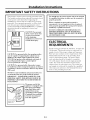 3
3
-
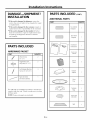 4
4
-
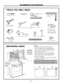 5
5
-
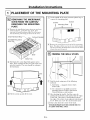 6
6
-
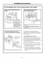 7
7
-
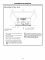 8
8
-
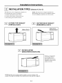 9
9
-
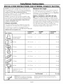 10
10
-
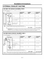 11
11
-
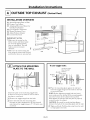 12
12
-
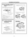 13
13
-
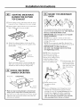 14
14
-
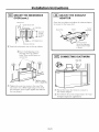 15
15
-
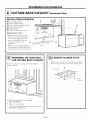 16
16
-
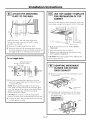 17
17
-
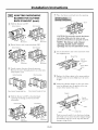 18
18
-
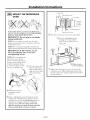 19
19
-
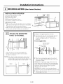 20
20
-
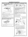 21
21
-
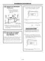 22
22
-
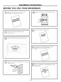 23
23
-
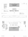 24
24
-
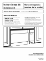 25
25
-
 26
26
-
 27
27
-
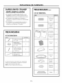 28
28
-
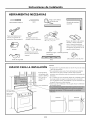 29
29
-
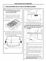 30
30
-
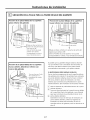 31
31
-
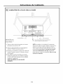 32
32
-
 33
33
-
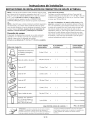 34
34
-
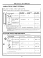 35
35
-
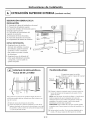 36
36
-
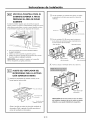 37
37
-
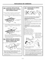 38
38
-
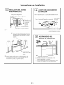 39
39
-
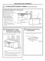 40
40
-
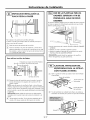 41
41
-
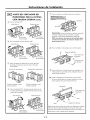 42
42
-
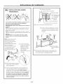 43
43
-
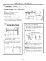 44
44
-
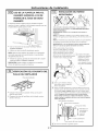 45
45
-
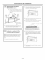 46
46
-
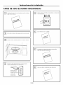 47
47
-
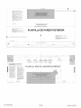 48
48


Kenmore Elite 79080379310 Guía de instalación
- Tipo
- Guía de instalación
- Este manual también es adecuado para
En otros idiomas
Documentos relacionados
Otros documentos
-
Frigidaire FMV152KQA Guía de instalación
-
Frigidaire FPBM3077RFA Guía de instalación
-
Kenmore 40185043210 Guía de instalación
-
-
Haier HMV1630DBBB Guía de instalación
-
-
Kenmore Pro 89393 Guía de instalación
-
GE JVM1631WK Guía de instalación
-
GE Profile EMO3000HBB Guía de instalación
-
Samsung ME21K6000AS/AA-01 Guía de instalación