Samsung ME21K6000AS/AA-01 Guía de instalación
- Categoría
- Microondas
- Tipo
- Guía de instalación
Este manual también es adecuado para

Installation Instructions
Over The Range Microwave Oven
BEFORE YOU BEGIN (Read these instructions completely and carefully.)
IMPORTANT
Save these instructions for local inspector’s use.
IMPORTANT
Observe all governing codes and ordinances.
• Note to Installer - Be sure to leave these instructions with the Consumer.
• Note to Consumer - Keep these instructions for future reference.
• Skill level - Installation of this appliance requires basic mechanical and electrical
skills.
• Proper installation is the responsibility of the installer.
• Product failure due to improper installation is not covered under the Warranty.
READ CAREFULLY. KEEP THESE INSTRUCTIONS.
ME21K6000AS_AA_DE68-04108C-00_EN.indd 1 5/20/2016 5:06:27 PM

2
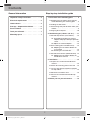
Contents
1. Placement of the mounting plate . . . . 8
A. Removing the microwave oven from the
carton/Removing the mounting plate . . 8
B. Finding the wall studs. . . . . . . . . . . 8
C. Determining wall plate location under your
cabinet . . . . . . . . . . . . . . . . . . 9
D. Aligning the wall plate. . . . . . . . . . 10
2. Ventilation types (choose a, b or c) . . . 11
A. Outside top exhaust (vertical duct). . . 12
A1. Installation procedure for exhaust
adaptor and proper damper operation
check . . . . . . . . . . . . . . . . 12
A2. Adjust the exhaust adaptor . . . . 12
B. Recirculating (non-vented ductless) . . 12
B1. Adapting the microwave blower for
recirculation . . . . . . . . . . . . 12
B2. Installing the charcoal filter . . . . 13
C. Outside back exhaust (horizontal duct) 14
C1. Adapting the microwave blower for
outside back exhaust . . . . . . . 14
3. Installation . . . . . . . . . . . . . . . . 15
A. Prepare the rear wall for outside back
exhaust . . . . . . . . . . . . . . . . . 15
B. Attach the mounting plate to the wall . 15
C. Use the top cabinet template to prepare
the top cabinet . . . . . . . . . . . . . 16
D. Mount the microwave oven . . . . . . . 16
E. Connect the ductwork for outside top
exhaust . . . . . . . . . . . . . . . . . .17
4. Before you use your microwave . . . . 18
Step-by-step installation guide
Important safety instructions . . . . . . . 3
Electrical requirements . . . . . . . . . . 3
Hood exhaust . . . . . . . . . . . . . . . . 4
Damage - Shipment/Installation. . . . . . 6
Parts included . . . . . . . . . . . . . . . 6
Tools you will need . . . . . . . . . . . . . 7
Mounting space. . . . . . . . . . . . . . . 7
General information
ME21K6000AS_AA_DE68-04108C-00_EN.indd 2 5/20/2016 5:06:27 PM

3
General information
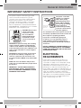
IMPORTANT SAFETY INSTRUCTIONS
This product requires a three-prong grounded
outlet. The installer must perform a ground
continuity check on the power outlet box before
beginning the installation to ensure that the
outlet box is properly grounded. If not properly
grounded, or if the outlet box does not meet
electrical requirements noted (under ELECTRICAL
REQUIREMENTS), a qualified electrician should be
employed to correct any deficiencies.
Insure proper
ground exists
before use
CAUTION: For personal
safety, remove the
house fuse or open
the circuit breaker
before beginning the
installation to avoid
severe or fatal shock
injury.
CAUTION: For personal safety, the mounting
surface must be capable of supporting the
cabinet load in addition to the added weight
of this 69 pound product, plus additional oven
loads of up to 50 pounds or a total weight of
109 pounds.
CAUTION: For personal safety, do not install
this product in cabinetry configured as an
island or a peninsula. The microwave oven
must be mounted to BOTH a top cabinet AND
a wall.
NOTE: For easier installation and personal
safety, we recommend that two people install
this product.
IMPORTANT – PLEASE READ CAREFULLY.
FOR PERSONAL SAFETY, THIS APPLIANCE
MUST BE PROPERLY GROUNDED TO AVOID
SEVERE OR FATAL SHOCK.
Insure proper
ground exists
before use
Insure proper
ground exists
before use.
The power cord of this
appliance is equipped
with a three-prong
(grounding) plug which
mates with a standard
three-prong (grounding)
wall receptacle to
minimize the possibility
of electric shock hazard
from this appliance.
You should have the wall receptacle and circuit
checked by a qualified electrician to make sure
the receptacle is properly grounded.
If you have a standard two-prong wall
receptacle, it is very important to have it
replaced with a properly grounded three-
prong wall receptacle, installed by a qualified
electrician.
DO NOT, UNDER ANY CIRCUMSTANCES, CUT,
DEFORM OR REMOVE ANY OF THE PRONGS
FROM THE POWER CORD. DO NOT USE WITH
AN EXTENSION CORD.
ELECTRICAL
REQUIREMENTS
Product rating is 120 volts AC, 60 Hertz, 14.5
amps and 1.7 kilowatts.This product must be
connected to a supply circuit of the proper voltage
and frequency. Wire size must conform to the
requirements of the National Electrical Code or the
prevailing local code for this kilowatt rating. The
power supply cord and plug should be brought to a
separate 15 ampere branch circuit single grounded
outlet. The outlet box should be located in the
cabinet above the microwave oven. The outlet box
and supply circuit should be installed by a qualified
electrician and conform to the National Electrical
Code or the prevailing local code.
ME21K6000AS_AA_DE68-04108C-00_EN.indd 3 5/20/2016 5:06:27 PM

4
General information
NOTE: Read these next two pages only if you plan to vent your exhaust to the outside. If you plan to
recirculate the air back into the room, proceed to page 11.
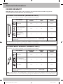
OUTSIDE TOP EXHAUST (EXAMPLE ONLY)
The following chart contains an example of one possible ductwork installation.
DUCT PIECES
EQUIVALENT
LENGTH
x
NUMBER
USED
=
EQUIVALENT
LENGTH
Roof Cap 24 ft. x (1) = 24 ft.
12 Ft. Straight Duct
(6” Round)
12 ft. x (1) = 12 ft.
Rectangular-to-
Round Transition
Adaptor*
5 ft. x (1) = 5 ft.
Equivalent lengths of duct pieces are based on actual tests
and reflect requirements for good venting performance with
any vent hood.
Total Length = 41 ft.
* IMPORTANT: If a rectangular-to-round transition adaptor is used, the bottom corners of the damper will have to be
cut to fit, using the tin snips, in order to allow free movement of the damper.
OUTSIDE BACK EXHAUST (EXAMPLE ONLY)
The following chart contains an example of one possible ductwork installation.
DUCT PIECES
EQUIVALENT
LENGTH
x
NUMBER
USED
=
EQUIVALENT
LENGTH
Wall Cap 40 ft. x (1) = 40 ft.
3 Ft. Straight Duct
(3¼” x 10” Rectangular)
3 ft. x (1) = 3 ft.
90° Elbow 10 ft. x (2) = 20 ft.
Equivalent lengths of duct pieces are based on actual tests
and reflect requirements for good venting performance with
any vent hood.
Total Length = 63 ft.
NOTE: For back exhaust, care should be taken to align the exhaust with the space between studs, or the wall should
be prepared at the time it is constructed by leaving enough space between the wall studs to accommodate exhaust.
HOOD EXHAUST
ME21K6000AS_AA_DE68-04108C-00_EN.indd 4 5/20/2016 5:06:28 PM

5
General information
NOTE: If you need to install ducts, note that the total
duct length of 3¼” x 10” rectangular or 6” diameter
round duct should not exceed 140 equivalent feet.
Outside ventilation requires a HOOD EXHAUST DUCT.
Read the following carefully.
NOTE: It is important that venting be installed using
the most direct route and with as few elbows as
possible. This ensures clear venting of exhaust and
helps prevent blockages. Also, make sure dampers
swing freely and nothing is blocking the ducts.
Exhaust connection:
The hood exhaust has been designed to mate with a
standard 3¼” x 10” rectangular duct.
If a round duct is required, a rectangular-to-round
transition adaptor must be used. Do not use less
than a 6” diameter duct.
Maximum duct length:
For satisfactory air movement, the total duct length
of 3¼” x 10” rectangular or 6” diameter round duct
should not exceed 140 equivalent feet.
Elbows, transitions, wall and roof
caps, etc. present additional resistance to airflow
and are equivalent to a section of straight duct which is
longer than their actual physical size. When calculating
the total duct length, add the equivalent lengths of all
transitions and adaptors plus the length of all straight
duct sections. The chart below shows you how to
calculate total equivalent ductwork length using the
equivalent length in feet of some typical ducts.
DUCT PIECES
EQUIVALENT
LENGTH
x
NUMBER
USED
=
EQUIVALENT
LENGTH
Rectangular-to-Round
Transition Adaptor*
5 ft. x ( ) = ft.
Wall Cap 40 ft. x ( ) = ft.
90° Elbow 10 ft. x ( ) = ft.
45° Elbow 5 ft. x ( ) = ft.
90° Elbow 25 ft. x ( ) = ft.
45° Elbow 5 ft. x ( ) = ft.
Roof Cap 24 ft. x ( ) = ft.
Straight Duct 6” Round or
3¼” x 10” Rectangular
1 ft. x ( ) = ft.
Total Ductwork = ft.
* IMPORTANT: If a rectangular-to-round
transition adaptor is used, the bottom
corners of the damper will have to be cut to
fit, using tin snips, to allow free movement
of the damper.
Equivalent lengths of duct pieces
are based on actual tests and reflect
the requirements for good venting
performance with any vent hood.
ME21K6000AS_AA_DE68-04108C-00_EN.indd 5 5/20/2016 5:06:28 PM

6
General information
• If the unit is damaged in shipment, return the unit to the store in which it was bought for repair or
replacement.
• If the unit is damaged by the customer, repair or replacement is the responsibility of the customer.
• If the unit is damaged by the installer (if other than the customer), repair or replacement must be made by
arrangement between the customer and installer.
DAMAGE - SHIPMENT/INSTALLATION
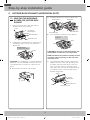
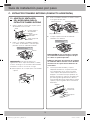
HARDWARE PACKET
PART QUANTITY
Template
INSTALLATION
INSTRUCTIONS
Wood Screws
(¼” x 2”)
1
Template
INSTALLATION
INSTRUCTIONS
Toggle Bolts
(and wing nuts)
(
3
/
16
” x 3”)
2
Template
INSTALLATION
INSTRUCTIONS
Self-aligning
Machine Screws
(¼” - 28 x 3¼”)
2
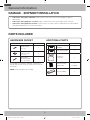
You will find the installation hardware contained in a
packet with the unit. Check to make sure you have all
these parts.
NOTE: Some extra parts are included.
ADDITIONAL PARTS
PART QUANTITY
TOP CABINET TEMPLATE
REAR WALL TEMPLATE
Top Cabinet
Template
1
TOP CABINET TEMPLATE
REAR WALL TEMPLATE
Rear Wall Template 1
Installation
Instructions
1
One Touch Easy
Grease Filter
1
(Installed)
Template
INSTALLATION
INSTRUCTIONS
Exhaust adaptor 1
PARTS INCLUDED
ME21K6000AS_AA_DE68-04108C-00_EN.indd 6 5/20/2016 5:06:29 PM

7
General information
#1 and #2 Phillips
screwdriver
Pencil Ruler or tape measure and
straight edge
Carpenter square (optional)
Tin snips (for cutting
damper, if required)
Scissors (to cut
template, if necessary)
Electric drill with
3
/
16
”, ½” and
⅝” drill bits
Filler blocks or scrap wood
pieces, if needed for top
cabinet spacing (used on
recessed bottom cabinet
installations only)
Gloves Saw (saber, hole or
keyhole)
Stud finder or Hammer
(optional)
Safety goggles
Level Duct and masking tape
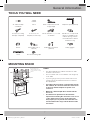
TOOLS YOU WILL NEED
16 ½”
30”
5”
30” min.
Bottom edge of the
cabinet needs to be 30”
or more from the cooking
surface.
Backsplash
NOTES:
• The space between the cabinets must be 30” wide
and free of obstructions.
• This microwave oven is for installation over ranges up
to 36” wide.
• If you are going to vent your microwave oven to the
outside, see the Hood Exhaust Section for exhaust
duct preparation.
• If installing the microwave oven beneath smooth
flat cabinets, be careful to follow the instructions
on the top cabinet template for power cord
clearance.
• Maximum cabinet depth above and beside the
unit is 12”.
• The dimensions provided are the minimum
required for mounting the microwave oven. Local
codes and the practical use of the range will
likely require you to provide more than the 13.5”
shown between the range and the bottom of the
microwave.
MOUNTING SPACE
12” max.
ME21K6000AS_AA_DE68-04108C-00_EN.indd 7 5/20/2016 5:06:30 PM

8
Step-by-step installation guide
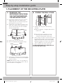
1. PLACEMENT OF THE MOUNTING PLATE
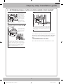
A. REMOVING THE
MICROWAVE OVEN FROM
THE CARTON/REMOVING
THE MOUNTING PLATE
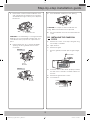
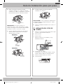
1. Remove the installation instructions, Exhaust
adaptor, filters, glass tray, and the small
hardware bag. Do not remove the Styrofoam
protecting the front of the oven.
2. Fold back all 4 carton flaps fully against carton
sides. Then carefully roll the oven and carton
over onto the top side. The oven should be
resting in the Styrofoam.
Styrofoam
Carton
Carton
Styrofoam
3. Pull the carton up and o the oven.
4. Remove and properly discard plastic bags.
Screws
Screws
Mounting Plate
Screws
Mounting Plate
Screws
5. Remove the 2 screws from the mounting plate.
This plate will be used as the rear wall template
and for mounting.
NOTE: Retain the two screws. You will need to re-
insert the screws in their original locations after you
have removed the mounting plate.
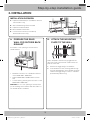
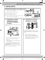
B. FINDING THE WALL STUDS
Wall Studs
Center
Center
Wall Studs
1. Find the studs using one of the following
methods:
A. With a stud finder – a magnetic device which
locates nails.
OR
B. Use a hammer to tap lightly across the
mounting surface until you hear a solid
sound. This will indicate a stud location.
2. After locating the stud(s), locate the stud’s center
by probing the wall with a small nail to find the
edges of the stud. Then, place a mark halfway
between the edges. The center of any adjacent
studs should be 16” or 24” from this mark.
3. Draw a line down the center of the studs.
THE MICROWAVE MUST BE CONNECTED TO
AT LEAST ONE WALL STUD.
ME21K6000AS_AA_DE68-04108C-00_EN.indd 8 5/20/2016 5:06:30 PM

9
Step-by-step installation guide
C. DETERMINING WALL PLATE LOCATION UNDER YOUR CABINET
C
L
Plate position – beneath a flat bottom cabinet.
Draw a vertical line on
the wall at the center
of the 30” wide space.
Tape the Rear Wall
Template onto the wall
so that the top of the
template touches the
bottom of the cabinet
and the centerline on
the template lines up
with the line you drew on
the wall.
At least 30”
16½”
C
L
Plate position – beneath recessed bottom
cabinet with front overhang
Draw a line on the
back wall equal to the
depth of the front
overhang.
30" to Cooktop
Plate position – beneath a recessed bottom cabinet
with a front overhang.
30” to Cooktop
Draw a horizontal line to
mark how far the inside
of the front overhang
descends below the
cabinet.
C
L
Plate position – beneath a framed recessed cabinet
bottom.
30” to Cooktop
Draw a vertical line on the wall at the center of the 30” wide
space. Tape the Rear Wall Template onto the wall so that the
top of the template touches the bottom of the cabinet frame
and the centerline on the template lines up with the line you
drew on the wall.
Your cabinets may have decorative trim that interferes
with the microwave installation. Remove the decorative
trim to install the microwave properly and to make it
level.
THE MICROWAVE MUST BE LEVEL.
Use a level to make sure the cabinet bottom is level.
Draw a vertical line on the wall at the center of the 30” wide
space. Draw a second, horizontal line on the wall below
the cabinet to mark how far the inside of the front overhang
descends below the cabinet. Tape the Rear Wall Template
onto the wall so that the top of the template touches the
bottom of the horizontal line and the centerline on the
template lines up with the vertical line.
ME21K6000AS_AA_DE68-04108C-00_EN.indd 9 5/20/2016 5:06:31 PM

10
Step-by-step installation guide
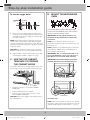
D. ALIGNING THE WALL PLATE
C
L
CAUTION: Wear gloves to avoid cutting
fingers on sharp edges.
Area E
Hole B
Hole A
Centerline
notches
Draw a Vertical Line
on Wall from Center
of Top Cabinet
Draw a Horizontal line on wall from
bottom of “Rear Wall Template”.
Horizontal Line
Horizontal Line
Draw a horizontal line on the wall along the bottom of
the “Rear Wall Template”.
Draw a vertical line on the
wall to mark the center of
the cabinet above.
Horizontal Line
Horizontal Line Area E
Centerline
notches
Hole A
Hole B
CAUTION: Wear gloves to avoid cutting fingers
on sharp edges.
1. Draw a horizontal line on the wall at the
bottom of the “Rear Wall Template”.
2. Drill ⅝” holes for toggle bolts in 3 locations
(Hole A, Hole B, Hole C) as shown in the
illustration above. If the location of a hole
lines up with a stud, drill a
3
/
16
” hole for a
wood screw. You cannot use a toggle bolt to
attach the wall plate to a stud.
NOTE: DO NOT MOUNT THE PLATE AT
THIS TIME.
3. Holes A, B and C are inside area E. If none
of these holes line up with a stud, find a stud
in area E that lines up with a hole circle in
Area E, and then drill a
3
/
16
” hole into it for
a wood screw. You must have at least one
wood screw mounted firmly into a stud to
support the weight of the microwave. Set
the mounting plate aside.
ME21K6000AS_AA_DE68-04108C-00_EN.indd 10 5/20/2016 5:06:31 PM

11
Step-by-step installation guide
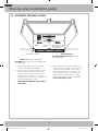
2. VENTILATION TYPES (CHOOSE A, B OR C)
This microwave oven is compatible with the following
three types of ventilation:
A. Outside Top Exhaust (Vertical Duct)
B. Recirculating (Non-Vented Ductless)
C. Outside Back Exhaust (Horizontal Duct)
NOTE: This microwave is shipped assembled
for Outside Top Exhaust (except for non-vented
models). An exhaust adaptor is shipped assembled
and attached to the filler-upper. Select the type of
ventilation required for your installation and proceed to
that section.
A. OUTSIDE TOP EXHAUST
(VERTICAL DUCT)
B. RECIRCULATING (NON-
VENTED DUCTLESS)
Adaptor in Place
for Outside
Top Exhaust
Adaptor in Place
for Outside Top
Exhaust
See page 12 See page 12, Part B
IMPORTANT: You must install the included Charcoal
Filter if you select nonvented exhaust. The charcoal
filter is provided with the unit.
C. OUTSIDE BACK EXHAUST
(HORIZONTAL DUCT)
See page 14
ME21K6000AS_AA_DE68-04108C-00_EN.indd 11 5/20/2016 5:06:31 PM

12
Step-by-step installation guide
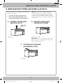
A. OUTSIDE TOP EXHAUST
(VERTICAL DUCT)
A1. INSTALLATION PROCEDURE FOR
THE EXHAUST ADAPTOR AND
PROPER DAMPER OPERATION
CHECK
The exhaust Adaptor and Damper are
shipped assembled and attached to
the filler-upper.
1. Slide the exhaust adaptor into place as shown
in the diagram above.
2. Make sure the tape securing the damper is
removed and damper pivots easily before you
mount the microwave.
CAUTION: You will need to make adjustments to
assure proper alignment with your house exhaust
duct after the microwave is installed.
A2. ADJUST THE EXHAUST ADAPTOR
After you have installed the microwave, you will
need to open the top cabinet and adjust the exhaust
adaptor so that you can connect it to the house
duct.
For Front-to-Back
Adjustment, Slide the
Exhaust Adaptor as Needed
Blower Plate
Back of
Microwave
Damper
NOTE: You must attach the house duct to the
exhaust adaptor after installation is complete.
House Duct
House Duct
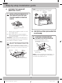
B. RECIRCULATING (NON-VENTED
DUCTLESS)
B1. ADAPTING THE MICROWAVE
BLOWER FOR RECIRCULATION
2. Lift up the
blower plate.
1. Remove and save the screws
that hold the blower plate to the
microwave.
Back of
Microwave
NOTE: The exhaust adaptor with the damper is not
needed for recirculating models. You may want to
save them for possible future use.
ME21K6000AS_AA_DE68-04108C-00_EN.indd 12 5/20/2016 5:06:32 PM

13
Step-by-step installation guide
3. Remove the screw that holds the blower motor
and carefully pull out the blower unit. The wires
will extend far enough to allow you to adjust the
blower unit.
blower mortor screw
CAUTION: To avoid breaking or cracking the blower
blade, do not touch the blade. Hold the outer case
of the blower when you pull it out or put it back in
place.
4. Roll the blower unit 90° so that the fan blade
openings are facing toward the front of the
microwave.
Back of
Microwave
Before Roll
After Roll
Back of
Microwave
5. Place the blower unit back into the opening.
CAUTION: Do not pull or stretch the blower unit
wiring. Make sure the wires are not pinched.
6. Secure the blower unit to the microwave with the
screw.
B2. INSTALLING THE CHARCOAL
FILTER
1. Remove the screws on the top of the grille using
a #1 Phillips screwdriver.
2. Open the door.
3. Remove the grille.
• Push the grille left, and then pull the grille straight
o.
Charcoal filter
4. Install the charocal filter. When properly installed,
the wire mesh of the filter should be visible from
the front.
5. Reinstall the grille and the screws.
6. Close the door.
Insert mesh-side up
ME21K6000AS_AA_DE68-04108C-00_EN.indd 13 5/20/2016 5:06:32 PM

14
Step-by-step installation guide
C. OUTSIDE BACK EXHAUST (HORIZONTAL DUCT)
C1. ADAPTING THE MICROWAVE
BLOWER FOR OUTSIDE BACK
EXHAUST
1. Remove and save the screws that hold the
Blower Plate to the microwave.
2. Lift up the
Blower plate.
Screw
Blower Motor
Back of Microwave
Blower Plate Screw
3. Carefully pull out the blower unit. The wires will
extend far enough to allow you to adjust the
blower unit.
BEFORE: Fan Blade
Openings Facing Forward
End B
End A
CAUTION: To avoid breaking or cracking the blower
blade, do not touch the blade. Hold the outer case
of the blower when you pull it out or put it back in
place.
4. Remove Parts “A” with tin snips or pliers.
Parts “A”
5. Rotate the blower unit counterclockwise 180°.
Before Rotation After Rotation
Back of Microwave
Back of Microwave
6. Place the blower unit back into the opening.
AFTER: Fan Blade Openings
Facing Back
End B
End A
CAUTION: Do not pull or stretch the blower unit
wiring. Make sure the wires are not pinched.
NOTE: The blower unit exhaust openings should
match the exhaust openings on the rear of the
microwave oven.
7. Close the Blower Plate and attach the exhaust
adaptor to the rear of the oven by sliding it into
the guides at the back top center of the oven.
Push in securely until it is in the lower locking
tabs. Take care to ensure that the damper hinge
is installed so that it is at the top and that the
damper swings freely.
Blower plate screw
Adaptor
Guide
Back of
Microwave
Guide
Blower motor screw
ME21K6000AS_AA_DE68-04108C-00_EN.indd 14 5/20/2016 5:06:33 PM

15
Step-by-step installation guide
B. ATTACH THE MOUNTING
PLATE TO THE WALL
Attach the plate to the wall using toggle bolts. At
least one wood screw must be used to attach the
plate to a wall stud.
1. Remove the toggle wings from the bolts.
2. Insert the bolts into the mounting plate through
the holes designated to go into drywall, and then
reattach the toggle wings so that ¾” of the bolt
protrudes beyond the wing.
INSTALLATION OVERVIEW
A. Prepare the Rear Wall (for outside back exhaust/
horizontal duct only)
B. Attach the Mounting Plate to the Wall
C. Prepare the Cabinet above
D. Mount the Microwave Oven
E. Connect the Ductwork (for outside top
exhaust/vertical duct only)
A. PREPARE THE REAR
WALL FOR OUTSIDE BACK
EXHAUST
You need to cut an opening in the rear wall for
outside exhaust.
C
L
• Read the instructions for outside back exhaust
on the REAR WALL TEMPLATE.
• Tape the REAR WALL TEMPLATE to the rear
wall.
• Cut the opening, following the instructions on the
REAR WALL TEMPLATE.
CAUTION: Do not cut an opening in the rear wall if
you are installing the microwave with vertical duct or
non-vented ductless ventilation.
3. INSTALLATION
ME21K6000AS_AA_DE68-04108C-00_EN.indd 15 5/20/2016 5:06:33 PM

16
Step-by-step installation guide
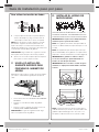
To use the toggle bolts:
Wall
Toggle Wings
Toggle
Bolt
Bolt End
Spacing for Toggles More
Than Wall Thickness
Mounting
Plate
Bolt End
Mounting
Plate
Toggle
Bolt
Wall
Toggle Wings
3. Place the mounting plate against the wall, pinch
the wings of each toggle together, and then insert
the toggle wings of each toggle into and through
the holes in the wall.
NOTE: Before tightening the toggle bolts and wood
screw, make sure the bottom of the Mounting plate
runs along the bottom Horizontal line of the “Rear wall
Template” and the Mounting plate is properly centered
under the cabinet.
CAUTION: Be careful to avoid pinching your fingers
between the back of the mounting plate and the wall.
4. Tighten all bolts. Pull the plate away from the wall
to help tighten the bolts. Tighten the screw.
C. USE THE TOP CABINET
TEMPLATE TO PREPARE
THE CABINET ABOVE
You need to drill holes for the top support screws and
a hole large enough for the power cord to fit through.
• Read the instructions on the TOP CABINET
TEMPLATE.
• Tape it underneath the top cabinet.
• Drill the holes, following the instructions on the
TOP CABINET TEMPLATE.
CAUTION: Wear safety goggles when drilling holes in
the cabinet bottom.
D. MOUNT THE MICROWAVE
OVEN
FOR EASIER INSTALLATION AND PERSONAL
SAFETY, WE RECOMMEND THAT TWO PEOPLE
INSTALL THIS MICROWAVE OVEN.
IMPORTANT: Do not grip the handle or use
the handle during installation to support the
microwave.
NOTE: If your cabinet is metal, use the nylon
grommet in the power cord hole to prevent the cord
from being cut.
NOTE: Filler blocks are required when mounting this
unit under any cabinet with a recessed bottom or
front overhang. (See page 9.)
IMPORTANT: The case damage that will occur
from over tightening screws if you do not use
filler blocks is not covered under warranty.
IMPORTANT: For models with the grease filter
installed, don’t push up on the filter when you
mount the oven.
NOTE: When mounting the microwave oven, thread
the power cord through hole in the bottom of the top
cabinet. Keep it tight throughout Steps 1–3. Do not
Grease Filter
Grease Filter
ME21K6000AS_AA_DE68-04108C-00_EN.indd 16 5/20/2016 5:06:34 PM

17
Step-by-step installation guide
pinch the cord or lift the oven by pulling cord.
1. Lift the microwave, tilt
it forward, and hook
the slots at the back
bottom edge onto the
four lower tabs of the
mounting plate.
2. Rotate the front of
the oven up against
the cabinet bottom.
3. Insert a self-aligning screw through the top
center cabinet hole. Temporarily secure the oven
by turning the screw at least two full turns after
the threads have engaged. (It will be completely
tightened later.) Be sure to keep the power
cord tight. Be careful not to pinch the cord,
especially when mounting flush to the
bottom of the cabinet.
Cabinet Front
Filler Block
Microwave Oven Top
Self-Aligning Screw
Equivalent to
Depth of
Cabinet Recess
Cabinet Bottom Shelf
Equivalent
to Depth of
Cabinet Recess
Cabinet Bottom Shelf
Microwave Oven Top
Cabinet Front
Filler Block
Self-Aligning Screw
4. Attach the microwave oven to the top cabinet.
5. Insert the 2 self-aligning screws through the
cabinet bottom and, if used, through the filler
blocks into the outer top of the unit. (See the
illustration above). Continue to support the unit
until both screws are inserted and engaged at
least two full turns, then fully tighten both screws
until the unit is secure.
6. Install the grease filters. See the Owner’s Manual
packed with the microwave for instructions.
NOTE: For models with installed grease filters, you
do not need to install a filter
E. CONNECT THE DUCTWORK
FOR OUTSIDE TOP
EXHAUST
House Duct
House Duct
1. Extend the house duct down to connect to the
exhaust adaptor.
2. Seal the exhaust duct joints using duct tape.
ME21K6000AS_AA_DE68-04108C-00_EN.indd 17 5/20/2016 5:06:34 PM

18
Before You Use Your Microwave
1. Make sure the microwave oven has been
installed according to instructions.
2. Remove all packing material from the
microwave oven.
3. Install the turntable and ring in the cavity.
4. Replace the house fuse or turn the breaker
back on.
Insure proper
ground exists
before use
5. Plug the power cord into a dedicated 15 amp
electrical outlet.
Insure proper
ground exists
before use
Insure proper
ground exists
before use.
6. Read the Owner’s Manual.
7. Keep installation instructions for the local
inspector’s use.
4. BEFORE YOU USE YOUR MICROWAVE
ME21K6000AS_AA_DE68-04108C-00_EN.indd 18 5/20/2016 5:06:34 PM

19
Notes
ME21K6000AS_AA_DE68-04108C-00_EN.indd 19 5/20/2016 5:06:34 PM

DE68-04108C-00
ME21K6000AS_AA_DE68-04108C-00_EN.indd 20 5/20/2016 5:06:34 PM

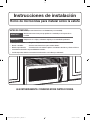
Instrucciones de instalación
Horno de microondas para instalar sobre la estufa
ANTES DE COMENZAR(Lea estas instrucciones con detenimiento y en su totalidad).
IMPORTANTE
Guarde estas instrucciones para que puedan ser consultadas por el inspector de su
localidad.
IMPORTANTE
Cumpla todos los códigos y ordenanzas exigidos por las autoridades pertinentes.
• Nota para el instalador - Asegúrese de dejarle estas instrucciones al cliente.
• Nota al consumidor - Conserve estas instrucciones para consultas futuras.
• Nivel de especialización - La instalación de este artefacto requiere conocimientos mecánicos y eléctricos básicos.
• La instalación adecuada es responsabilidad del instalador.
• La falla del producto debido a una instalación inadecuada no está cubierta por la Garantía.
LEA DETENIDAMENTE. CONSERVE ESTAS INSTRUCCIONES.
ME21K6000AS_AA_DE68-04108C-00_MES.indd 1 5/20/2016 5:06:43 PM

2
Contenido
1. Colocación de la placa de montaje . . . . . . . . . . 8
A. Quitar el horno de microondas de la caja/Quitar la
placa de montaje . . . . . . . . . . . . . . . . . . . 8
B. Buscar los montantes de pared. . . . . . . . . . . .8
C. Determinar la ubicación de la placa de pared bajo su
gabinete . . . . . . . . . . . . . . . . . . . . . . . . 9
D. Alinear la placa de pared . . . . . . . . . . . . . . 10
2. Tipos de ventilación (seleccione a, b o c) . . . . . 11
A. Extractor superior externo (conducto vertical) . . . 12
A1. Procedimiento de instalación para el adaptador
del extractor y verificación del funcionamiento
adecuado del regulador de tiro de humo . . . 12
A2. Ajustar el adaptador del extractor. . . . . . . 12
B. Recirculación (sin ventilación, sin conductos) . . . 12
B1. Adaptar el ventilador del microondas para la
recirculación . . . . . . . . . . . . . . . . . . 12
B2. Instalación del filtro de carbón . . . . . . . . 13
C. Extractor trasero externo (conducto horizontal) . . 14
C1. Adaptar el ventilador del microondas para el
extractor trasero externo . . . . . . . . . . . 14
3. Instalación . . . . . . . . . . . . . . . . . . . . . . 15
A. Preparar la pared posterior para el extractor trasero
externo . . . . . . . . . . . . . . . . . . . . . . . . 15
B. Sujetar la placa de montaje a la pared . . . . . . . 15
C. Usar la plantilla del gabinete superior para preparar el
gabinete superior . . . . . . . . . . . . . . . . . . 16
D. Instalar el horno de microondas . . . . . . . . . . 16
E. Conectar la red de conductos para el extractor
superior externo . . . . . . . . . . . . . . . . . . . .17
4. Antes de utilizar el microondas . . . . . . . . . . . 18
Guía de instalación paso por paso
Instrucciones de seguridad importantes . . . . . . . . 3
Requisitos eléctricos . . . . . . . . . . . . . . . . . . . 3
Extractor de campana . . . . . . . . . . . . . . . . . . 4
Daños - Envío/Instalación . . . . . . . . . . . . . . . . 6
Piezas incluidas. . . . . . . . . . . . . . . . . . . . . . 6
Herramientas necesarias. . . . . . . . . . . . . . . . . 7
Espacio de instalación . . . . . . . . . . . . . . . . . . 7
Información general
ME21K6000AS_AA_DE68-04108C-00_MES.indd 2 5/20/2016 5:06:43 PM

3
Información general
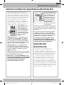
INSTRUCCIONES DE SEGURIDAD IMPORTANTES
Este producto requiere un tomacorriente con
conexión a tierra de tres pines. El instalador debe
verificar la continuidad de la conexión a tierra en la
caja de distribución eléctrica antes de comenzar la
instalación para asegurar que la caja de distribución
esté correctamente conectada a tierra. Si no
está conectada a tierra como corresponde, o si
la caja de distribución eléctrica no cumple los
requisitos eléctricos señalados (en REQUISITOS
ELÉCTRICOS), debe contratarse a un electricista
calificado para corregir cualquier deficiencia.
Insure proper
ground exists
before use
PRECAUCIÓN: Para su
seguridad personal,
quite el fusible de la
casa o abra el disyuntor
antes de comenzar la
instalación para evitar
lesiones por descargas
eléctricas graves o
fatales.
PRECAUCIÓN: Para su seguridad personal,
la superficie de montaje debe ser capaz de
soportar la carga del gabinete, además del
peso agregado de este producto de 69 libras,
más las cargas adicionales del horno de hasta
50 libras o un peso total de 109 libras.
PRECAUCIÓN: Para su seguridad personal,
no instale este producto en gabinetes tipo
isla o península. El horno de microondas debe
instalarse TANTO en un gabinete superior
COMO en la pared.
NOTA: Para una instalación más sencilla y para
su seguridad personal, recomendamos que dos
personas instalen este producto.
IMPORTANTE - LEA DETENIDAMENTE. PARA
SU SEGURIDAD PERSONAL, ESTE ARTEFACTO
DEBE ESTAR CORRECTAMENTE CONECTADO
A TIERRA PARA EVITAR DESCARGAS
ELÉCTRICAS GRAVES O FATALES.
Insure proper
ground exists
before use
Asegúrese de
que exista una
conexión a
tierra adecuada
antes de utilizar
el horno de
microondas.
El cable de alimentación
de este artefacto cuenta
con un enchufe de tres
pines (con conexión a
tierra) que se conecta
al tomacorriente de tres
pines (con conexión a
tierra) para minimizar
la posibilidad de
descargas eléctricas de
este artefacto.
Un electricista calificado debe inspeccionar el
tomacorriente y el circuito para asegurarse de
que el tomacorriente tenga la conexión a tierra
adecuada.
En caso de tener un tomacorriente de pared
estándar de dos pines, es muy importante
reemplazarlo por un tomacorriente de pared
de tres pines con conexión a tierra adecuada,
instalado por un electricista calificado.
BAJO NINGUNA CIRCUNSTANCIA CORTE,
DEFORME O QUITE CUALQUIERA DE LOS
PINES DEL CABLE DE ALIMENTACIÓN. NO LO
UTILICE CON UN CABLE ALARGADOR.
REQUISITOS
ELÉCTRICOS
La potencia de servicio del producto es de
120voltios CA, 60 hertz, 14,5 amperes y
1,7kilovatios. Este producto debe conectarse a un
circuito de alimentación con el voltaje y la frecuencia
adecuados. El tamaño del cable debe adecuarse
a los requerimientos del Código Eléctrico Nacional
o el código local vigente para esta potencia de
kilovatios. El cable de alimentación eléctrica y el
enchufe deben conectarse a un tomacorriente
con conexión a tierra único con circuito derivado
de 15amperes separado. La caja de distribución
eléctrica debe estar ubicada en el gabinete arriba del
horno de microondas. Un electricista calificado debe
instalar la caja de distribución eléctrica y el circuito
de alimentación y éstos deben cumplir con el Código
Eléctrico Nacional o el código local vigente.
ME21K6000AS_AA_DE68-04108C-00_MES.indd 3 5/20/2016 5:06:43 PM

4
Información general
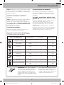
NOTA: Lea estas dos páginas siguientes solamente si planifica dar salida al exterior al extractor.
Si planifica hacer recircular el aire nuevamente a la habitación, pase a la página 11.
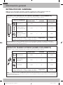
EXTRACTOR SUPERIOR EXTERNO (EJEMPLO SOLAMENTE)
El siguiente cuadro contiene un ejemplo de una posible instalación de la red de conductos.
PIEZAS DE CONDUCTOS
LONGITUD
EQUIVALENTE
x
CANTIDAD
UTILIZADA
=
LONGITUD
EQUIVALENTE
Tapa de techo 24 pies x (1) = 24 pies
12 pies Conducto
recto (Redondo de 6”)
12 pies x (1) = 12 pies
Adaptador de
transición rectangular
a redondo*
5 pies x (1) = 5 pies
Las longitudes equivalentes de las piezas de los conductos están
basadas en pruebas reales y reflejan los requisitos de un buen
desempeño de ventilación con cualquier campana de ventilación.
Longitud total = 41 pies
* IMPORTANTE: Si se utiliza un adaptador de transición de rectangular a redondo, las esquinas inferiores del
regulador de tiro de humo deberán cortarse para encajar, utilizando las tijeras para cortar metales, con el fin de
permitir el movimiento libre del regulador de tiro.
EXTRACTOR TRASERO EXTERNO (EJEMPLO SOLAMENTE)
El siguiente cuadro contiene un ejemplo de una posible instalación de la red de conductos.
PIEZAS DE CONDUCTOS
LONGITUD
EQUIVALENTE
x
CANTIDAD
UTILIZADA
=
LONGITUD
EQUIVALENTE
Tapa de pared 40 pies x (1) = 40 pies
3 pies Conducto recto
(Rectangular de
3¼” x 10”)
3 pies x (1) = 3 pies
Codo de 90° 10 pies x (2) = 20 pies
Las longitudes equivalentes de las piezas de los conductos están
basadas en pruebas reales y reflejan los requisitos de un buen
desempeño de ventilación con cualquier campana de ventilación.
Longitud total = 63 pies
NOTA: Para el extractor trasero, se debe tener la precaución de alinear el extractor con el espacio entre los montantes,
o la pared debe prepararse en el momento en que se construye dejando suficiente espacio entre los montantes de
pared para colocar el extractor.
EXTRACTOR DE CAMPANA
ME21K6000AS_AA_DE68-04108C-00_MES.indd 4 5/20/2016 5:06:43 PM

5
Información general
NOTA: Si debe instalar conductos, observe que la longitud
total de los conductos rectangulares de 3¼”x10” o de los
conductos redondos de 6” de diámetro no debe superar los
140 pies equivalentes.
La ventilación externa requiere un CONDUCTO DE
EXTRACTOR DE CAMPANA. Lea lo siguiente con
detenimiento.
NOTA: Es importante que la ventilación se instale utilizando
la ruta más directa y con la menor cantidad de codos
posibles. Esto asegura la buena ventilación del extractor y
ayuda a evitar obstrucciones. Además, asegúrese de que
los reguladores de tiro se balanceen libremente y que
nada obstruya los conductos.
Conexión del extractor:
El extractor de campana se diseñó para coincidir con el
conducto rectangular de 3¼” x 10” estándar.
Si se necesita un conducto redondo, debe utilizarse un
adaptador de transición rectangular a redondo. No utilice
un conducto de menos de 6” de diámetro.
Longitud máxima del conducto:
Para una rotación de aire satisfactoria, la longitud total
del conducto rectangular de 3¼” x 10” o del conducto
redondo de 6” de diámetro no debe superar los 140pies
equivalentes.
Los codos, transiciones, tapas de techo
y pared, etc. presentan una resistencia adicional al flujo
de aire y son equivalentes a una sección del conducto recto
que es más extensa que su tamaño físico real.
Cuando calcule la longitud total del conducto, agregue
las longitudes equivalentes de todas las transiciones y
adaptadores más la longitud de todas las secciones de
conductos rectos.
El siguiente cuadro muestra cómo calcular la longitud total
equivalente de la red de conductos utilizando la longitud
equivalente en pies de algunos conductos típicos.
PIEZAS DE CONDUCTOS
LONGITUD
EQUIVALENTE
x
CANTIDAD
UTILIZADA
=
LONGITUD
EQUIVALENTE
Adaptador de transición
rectangular a redondo*
5 pies x ( ) = pies
Tapa de pared 40 pies x ( ) = pies
Codo de 90° 10 pies x ( ) = pies
Codo de 45° 5 pies x ( ) = pies
Codo de 90° 25 pies x ( ) = pies
Codo de 45° 5 pies x ( ) = pies
Tapa de techo 24 pies x ( ) = pies
Conducto recto redondo de 6”
o rectangular de 3¼” x 10”
1 pie x ( ) = pies
Red de conductos total = pies
* IMPORTANTE: Si se utiliza un adaptador
de transición de rectangular a redondo,
las esquinas inferiores del regulador de tiro
de humo deberán cortarse para encajar,
utilizando tijeras para cortar metales, a fin
de permitir el movimiento libre del regulador
de tiro.
Las longitudes equivalentes de las piezas
de los conductos están basadas en
pruebas reales y reflejan los requisitos de
un buen rendimiento de la ventilación con
cualquier campana de ventilación.
ME21K6000AS_AA_DE68-04108C-00_MES.indd 5 5/20/2016 5:06:43 PM

6
Información general
• Si la unidad se daña en el envío, devuelva la unidad a la tienda en la que la compró para su reparación o
reemplazo.
• Si el cliente daña la unidad, la reparación o el reemplazo es responsabilidad del cliente.
• Si el instalador daña la unidad (en caso de que sea una persona distinta al cliente), la reparación o el
reemplazo deben realizarse mediante un acuerdo entre el cliente y el instalador.
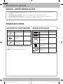
DAÑOS – ENVÍO/INSTALACIÓN
PAQUETE DE COMPONENTES
PIEZA CANTIDAD
Template
INSTALLATION
INSTRUCTIONS
Tornillos para
madera
(¼” x 2”)
1
Template
INSTALLATION
INSTRUCTIONS
Tornillos de fiador
(y tuercas tipo
mariposa)
(
3
/
16
” x 3”)
2
Template
INSTALLATION
INSTRUCTIONS
Tornillos mecánicos
autoalineables
(¼” - 28 x 3¼”)
2
Encontrará los componentes de instalación en un
paquete junto con la unidad. Asegúrese de tener todas
estas piezas.
NOTA: Se incluyen algunas piezas adicionales.
PIEZAS ADICIONALES
PIEZA CANTIDAD
TOP CABINET TEMPLATE
REAR WALL TEMPLATE
Plantilla del
gabinete superior
1
TOP CABINET TEMPLATE
REAR WALL TEMPLATE
Plantilla de la pared
trasera
1
Instrucciones de
instalación
1
Filtro de grasa
simple mediante un
solo botón
1
(Instalado)
Template
INSTALLATION
INSTRUCTIONS
Adaptador del
extractor
1
PIEZAS INCLUIDAS
ME21K6000AS_AA_DE68-04108C-00_MES.indd 6 5/20/2016 5:06:43 PM

7
Información general
Destornillador Phillips
#1 y #2
Lápiz Cinta métrica y regla Escuadra (opcional)
Tijeras para cortar
metales (para cortar
el regulador de tiro de
humo, si es necesario)
Tijeras (para cortar la
plantilla, si es necesario)
Taladro eléctrico con
mechas de
3
/
16
”, ½” y ⅝”
Bloques de relleno o pedacitos de
madera sobrantes, si se necesitan para
el espaciado del gabinete superior
(utilizados en instalaciones de gabinete
con parte inferior empotrada solamente)
Guantes Sierra (tipo sable, de
perforación o de calar)
Detector de montantes o
martillo (opcional)
Gafas de seguridad
Nivel Cinta adhesiva y para
conductos
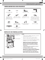
HERRAMIENTAS NECESARIAS
16 ½”
30”
5”
30” mín.
El borde inferior del
gabinete debe estar a
30”o más de la superficie
de cocción.
Protector contra salpicaduras
NOTAS:
• El espacio entre los gabinetes debe tener 30” de ancho
y no presentar obstrucciones.
• Este horno de microondas es adecuado para su
instalación sobre estufas de hasta 36” de ancho.
• Si su horno de microondas tendrá ventilación al exterior,
consulte la sección Extractor de campana para conocer
la preparación de los conductos del extractor.
• Si instala el horno de microondas debajo de
gabinetes lisos y planos, asegúrese de seguir
las instrucciones de la plantilla del gabinete
superior en cuanto al espacio para el cable de
alimentación.
• La profundidad máxima del gabinete encima y a
un lado de la unidad es de 12”.
• Las dimensiones proporcionadas son las
mínimas necesarias para el montaje del horno de
microondas. Los códigos locales y el uso práctico
de la estufa probablemente requerirán que
proporcione más de las 13,5” que se muestran
entre la estufa y la parte inferior del microondas.
ESPACIO DE INSTALACIÓN
12” máx.
ME21K6000AS_AA_DE68-04108C-00_MES.indd 7 5/20/2016 5:06:45 PM

8
Guía de instalación paso por paso
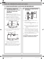
1. COLOCACIÓN DE LA PLACA DE MONTAJE
A. QUITAR EL HORNO DE
MICROONDAS DE LA CAJA/
QUITAR LA PLACA DE
MONTAJE
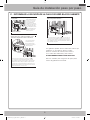
1. Retire las instrucciones de instalación, el
adaptador del extractor, los filtros, la charola de
vidrio y la bolsa de piezas pequeñas. No quite el
Styrofoam que protege el frente del horno.
2. Pliegue las 4 solapas de la caja contra los
laterales de la caja. Luego con cuidado gire el
horno y la caja y apóyelo sobre la parte superior.
El horno debe apoyarse sobre el Styrofoam.
Styrofoam
Carton
Caja
Styrofoam
3. Tire la caja hacia arriba para separarla del horno.
4. Quite y deseche las bolsas de plástico de la
manera adecuada.
Screws
Screws
Mounting Plate
Tornillos
Placa de montaje
Tornillos
5. Quite los 2 tornillos de la placa de montaje.
Esta placa se utilizará como la plantilla de la
pared trasera y para el montaje.
NOTA: Conserve los dos tornillos. Tendrá que volver
a insertar los tornillos en sus posiciones originales
después de haber retirado la placa de montaje.
B. BUSCAR LOS MONTANTES
DE PARED
Wall Studs
Center
Centro
Montantes de pared
1. Busque los montantes utilizando uno de los
siguientes métodos:
A. Con un detector de montantes - un
dispositivo magnético que localiza los clavos.
O
B. Utilice un martillo para golpear suavemente
la superficie de montaje hasta oír un sonido
sólido. Esto indicará la ubicación de un
montante.
2. Después de ubicar el(los) montante(s), localice
el centro sondeando la pared con un pequeño
clavo para encontrar los bordes. Luego, haga
una marca a mitad de camino entre los bordes.
El centro de cualquier montante adyacente debe
estar a 16” o 24” de esta marca.
3. Trace una línea vertical en el centro de los
montantes.
EL MICROONDAS DEBE ESTAR CONECTADO
AL MENOS A UN MONTANTE DE PARED.
ME21K6000AS_AA_DE68-04108C-00_MES.indd 8 5/20/2016 5:06:46 PM

9
Guía de instalación paso por paso
C.
DETERMINAR LA UBICACIÓN DE LA PLACA DE PARED BAJO SU GABINETE
C
L
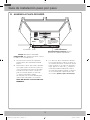
Posición de la placa - debajo de un gabinete con parte
inferior plana.
Trace una línea vertical en la
pared en el centro de este
espacio de 30” de ancho.
Pegue la plantilla de la
pared trasera en la pared de
manera que la parte superior
de la plantilla toque la parte
inferior del gabinete y la línea
central de la plantilla quede
alineada con la línea que
dibujó en la pared.
Al menos 30”
16½”
C
L
Plate position – beneath recessed bottom
cabinet with front overhang
Draw a line on the
back wall equal to the
depth of the front
overhang.
30" to Cooktop
Posición de la placa – debajo de un gabinete con la
parte inferior empotrada con frente sobresaliente.
30” a la cubierta
Trace una línea horizontal
para marcar hasta qué
punto el interior del frente
sobresaliente desciende por
debajo del gabinete.
C
L
Posición de la placa - debajo de la parte inferior de un
gabinete empotrado enmarcado.
30” a la cubierta
Trace una línea vertical en la pared en el centro de este espacio de
30”de ancho. Pegue la plantilla de la pared trasera en la pared de
manera que la parte superior de la plantilla toque la parte inferior del
marco del gabinete y la línea central de la plantilla quede alineada con
la línea que dibujó en la pared.
Sus gabinetes pueden tener molduras decorativas que
interfieren con la instalación del microondas.
Quite las molduras decorativas para instalar el
microondas adecuadamente y para nivelarlo.
EL MICROONDAS DEBE ESTAR NIVELADO.
Utilice un nivelador para asegurarse de que la parte
inferior del gabinete esté nivelada.
Trace una línea vertical en la pared en el centro de este espacio
de 30” de ancho. Trace una segunda línea horizontal en la pared
debajo del gabinete para marcar hasta qué punto el interior del frente
sobresaliente desciende por debajo del gabinete. Pegue la plantilla
de la pared trasera en la pared de manera que la parte superior de la
plantilla toque la parte inferior de la línea horizontal y la línea central de
la plantilla quede alineada con la línea vertical.
ME21K6000AS_AA_DE68-04108C-00_MES.indd 9 5/20/2016 5:06:46 PM

10
Guía de instalación paso por paso
D. ALINEAR LA PLACA DE PARED
C
L
CAUTION: Wear gloves to avoid cutting
fingers on sharp edges.
Area E
Hole B
Hole A
Centerline
notches
Draw a Vertical Line
on Wall from Center
of Top Cabinet
Draw a Horizontal line on wall from
bottom of “Rear Wall Template”.
Horizontal Line
Horizontal Line
Trace una línea horizontal en la pared a lo largo de la
parte inferior de la "plantilla de la pared trasera".
Trace una línea vertical
en la pared para marcar
el centro del gabinete
de arriba.
Línea horizontal
Línea horizontal Área E
Muescas
de la línea
central
Orificio A
Orificio B
PRECAUCIÓN: Use guantes para evitar cortarse
los dedos con los bordes filosos.
1. Trace una línea horizontal en la pared en
la parte inferior de la "plantilla de la pared
trasera".
2. Perfore orificios de ⅝” para tornillos de fiador
en 3 lugares (orificio A, orificio B y orificio C)
como se muestra en la ilustración de arriba.
Si la ubicación de un orificio coincide con
la de un montante, perfore un orificio de
3
/
16
”para un tornillo para madera.
No se puede usar un tornillo de fiador para
sujetar la placa de pared a un montante.
NOTA: NO INSTALE LA PLACA EN ESTE
MOMENTO.
3. Los orificios A, B y C están dentro del área
E. Si ninguno de estos orificios se alinea con
un montante, busque un montante en el área
E que se alinee con un orificio en el área E y,
luego, perfore un orificio de
3
/
16
” allí para un
tornillo para madera. Debe tener al menos
un tornillo para madera sujetado con firmeza
en un montante para soportar el peso del
microondas. Aparte la placa de montaje.
ME21K6000AS_AA_DE68-04108C-00_MES.indd 10 5/20/2016 5:06:47 PM

11
Guía de instalación paso por paso
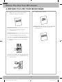
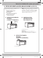
2. TIPOS DE VENTILACIÓN (SELECCIONE A, B O C)
Este horno de microondas es compatible con los
siguientes tres tipos de ventilación:
A. Extractor superior externo
(conducto vertical)
B. Recirculación
(sin ventilación, sin conductos)
C. Extractor trasero externo
(conducto horizontal)
NOTA: Este microondas se entrega con montaje para
un Extractor Superior Externo (excepto en los casos
de modelos sin ventilación). Se entrega un adaptador
del extractor ensamblado y unido al relleno superior.
Seleccione el tipo de ventilación requerido para su
instalación y avance a esa sección.
A. EXTRACTOR SUPERIOR
EXTERNO
(CONDUCTO VERTICAL)
B. RECIRCULACIÓN
(SIN VENTILACIÓN,
SIN CONDUCTOS)
Adaptor in Place
for Outside
Top Exhaust
Adaptador
colocado para el
extractor superior
externo
Consulte la página 12 Consulte la página 12,
sección B
IMPORTANTE: Si selecciona el extractor sin
ventilación, debe instalar el filtro de carbón incluido.
El filtro de carbón se suministra con la unidad.
C. EXTRACTOR TRASERO
EXTERNO
(CONDUCTO HORIZONTAL)
Consulte la página 14
ME21K6000AS_AA_DE68-04108C-00_MES.indd 11 5/20/2016 5:06:47 PM

12
Guía de instalación paso por paso
A.
EXTRACTOR SUPERIOR EXTERNO
(CONDUCTO VERTICAL)
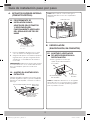
A1. PROCEDIMIENTO DE
INSTALACIÓN PARA EL
ADAPTADOR DEL EXTRACTOR
Y VERIFICACIÓN DEL
FUNCIONAMIENTO ADECUADO
DEL REGULADOR DE TIRO DE
HUMO
El adaptador del extractor y el regulador de
tiro se entregan ensamblados y unidos al
relleno superior.
1. Deslice el adaptador del extractor en su lugar
como se muestra en el diagrama de arriba.
2. Asegúrese de quitar la cinta adhesiva que fija el
regulador de tiro y de que el regulador de tiro
se balancee con facilidad antes de instalar el
microondas.
PRECAUCIÓN: Deberá hacer ajustes para asegurar
la correcta alineación con el conducto del extractor
de su casa después que el microondas esté
instalado.
A2. AJUSTAR EL ADAPTADOR DEL
EXTRACTOR
Después de haber instalado el microondas, tendrá
que abrir el gabinete superior y ajustar el adaptador
del extractor a fin de poder conectarlo al conducto
del hogar.
Para un ajuste de adelante
hacia atrás, deslice el
adaptador del extractor
según sea necesario
Placa del ventilador
Parte posterior
del microondas
Regulador de tiro de humo
NOTA: Debe sujetar el conducto del hogar al
adaptador del extractor una vez completada la
instalación.
House Duct
Conducto de la casa
B.
RECIRCULACIÓN
(SIN VENTILACIÓN, SIN CONDUCTOS)
B1. ADAPTAR EL VENTILADOR
DEL MICROONDAS PARA LA
RECIRCULACIÓN
2. Levante la placa
del ventilador.
1. Quite y guarde los tornillos que
sujetan la placa del ventilador al
microondas.
Parte
posterior del
microondas
NOTA: El adaptador del extractor con el regulador
de tiro de humo no es necesario para los modelos
de recirculación. Es posible que desee guardarlos
para un posible uso futuro.
ME21K6000AS_AA_DE68-04108C-00_MES.indd 12 5/20/2016 5:06:47 PM

13
Guía de instalación paso por paso
3. Retire el tornillo que sujeta el motor del
ventilador y extraiga con cuidado la unidad de
ventilador. Los cables se extenderán lo suficiente
para permitirle ajustar la unidad de ventilador.
tornillo del motor del
ventilador
PRECAUCIÓN: Para evitar la ruptura o el
agrietamiento de las aspas del ventilador, no debe
tocarlas. Sostenga la carcasa exterior del ventilador
al extraerlo o volver a colocarlo en su lugar.
4. Rote la unidad de ventilador 90° para que las
aberturas de las aspas miren hacia la parte
delantera del microondas.
Parte
posterior del
microondas
Antes de rotar
Después de rotar
Parte posterior
del microondas
5. Coloque la parte trasera de la unidad de
ventilador en la abertura.
PRECAUCIÓN: No tire ni extienda el cableado de la
unidad de ventilador. Asegúrese de que los cables
no queden apretados.
6. Sujete la unidad de ventilador al microondas con
el tornillo.
B2. INSTALACIÓN DEL FILTRO DE
CARBÓN
1. Retire los tornillos de la parte superior de la rejilla
usando un destornillador Phillips #1.
2. Abra la puerta.
3. Retire la rejilla.
• Empuje la rejilla hacia la izquierda y, luego,
retírela directamente.
Filtro de carbón
4. Instale el filtro de carbón.
Cuando esté correctamente instalado, la malla
metálica del filtro debe verse desde el frente.
5. Vuelva a instalar la rejilla y los tornillos.
6. Cierre la puerta.
Inserte el lado de la malla hacia arriba.
ME21K6000AS_AA_DE68-04108C-00_MES.indd 13 5/20/2016 5:06:48 PM

14
Guía de instalación paso por paso
C. EXTRACTOR TRASERO EXTERNO (CONDUCTO HORIZONTAL)
C1. ADAPTAR EL VENTILADOR
DEL MICROONDAS PARA EL
EXTRACTOR TRASERO EXTERNO
1. Quite y guarde los tornillos que sujetan la placa
del ventilador al microondas.
2. Levante la placa
del ventilador.
Tornillo
Motor del ventilador
Parte posterior del
microondas
Tornillo de la placa del
ventilador
3. Retire con cuidado la unidad de ventilador.
Los cables se extenderán lo suficiente para
permitirle ajustar la unidad de ventilador.
ANTES: Aberturas de las aspas del
ventilador hacia adelante
Extremo B
Extremo A
PRECAUCIÓN: Para evitar la ruptura o el
agrietamiento de las aspas del ventilador, no debe
tocarlas. Sostenga la carcasa exterior del ventilador
al extraerlo o volver a colocarlo en su lugar.
4. Quite las piezas “A” con tijeras para cortar metales
o pinzas.
Piezas “A”
5. Rote la unidad de ventilador en sentido contrario
a las agujas del reloj 180°.
Antes de la rotación Después de la rotación
Parte posterior del microondas
Parte posterior del microondas
6. Coloque la parte trasera de la unidad de
ventilador en la abertura.
DESPUÉS: Aberturas de las aspas
del ventilador hacia atrás
Extremo B
Extremo A
PRECAUCIÓN: No tire ni extienda el cableado
de la unidad de ventilador. Asegúrese de que
los cables no queden apretados.
NOTA: Las aberturas del extractor de la unidad
de ventilador deben coincidir con las aberturas
del extractor en la parte trasera del horno de
microondas.
7. Cierre la placa del ventilador y sujete el
adaptador del extractor a la parte trasera del
horno deslizándolo en las guías en la parte
central superior de la parte trasera del horno.
Empújelo con firmeza hasta que quede en las
pestañas de retención inferiores. Asegúrese de
que la bisagra del regulador de tiro de humo
esté instalada de manera que quede en la parte
superior y que el regulador de tiro se balancee
libremente.
Tornillo de la placa del
ventilador
Adaptador
Guía
Parte posterior
del microondas
Guía
Tornillo del motor del
ventilador
ME21K6000AS_AA_DE68-04108C-00_MES.indd 14 5/20/2016 5:06:48 PM

15
Guía de instalación paso por paso
B. SUJETAR LA PLACA DE
MONTAJE A LA PARED
Sujete la placa a la pared utilizando los tornillos
de fiador. Se debe utilizar al menos un tornillo de
madera para sujetar la placa a un montante de
pared.
1. Quite las mariposas de los tornillos.
2. Inserte los tornillos en la placa de montaje
a través de los orificios designados para
ingresar en el muro y, luego, vuelva a colocar
las mariposas de manera que ¾” del tornillo
sobresalga detrás de la mariposa.
DESCRIPCIÓN GENERAL DE LA INSTALACIÓN
A. Preparar la pared trasera (para el extractor trasero externo/
conducto horizontal solamente)
B. Sujetar la placa de montaje a la pared
C. Preparar el gabinete de arriba
D. Instalar el horno de microondas
E. Conectar la red de conductos (para el extractor superior
externo/conducto vertical solamente)
A. PREPARAR LA PARED
POSTERIOR PARA EL
EXTRACTOR TRASERO
EXTERNO
Puede hacer una abertura en la pared trasera para el
extractor externo.
C
L
• Lea las instrucciones para el extractor trasero
externo en la PLANTILLA DE LA PARED
TRASERA.
• Pegue la PLANTILLA DE LA PARED TRASERA
en la pared trasera.
• Recorte la abertura siguiendo las instrucciones
en la PLANTILLA DE LA PARED TRASERA.
PRECAUCIÓN: No haga una abertura en la pared
trasera si va a instalar el microondas con conducto
vertical o sin conductos sin ventilación.
3. INSTALACIÓN
ME21K6000AS_AA_DE68-04108C-00_MES.indd 15 5/20/2016 5:06:49 PM

16
Guía de instalación paso por paso
Para utilizar los tornillos de fiador:
Wall
Toggle Wings
Toggle
Bolt
Bolt End
Spacing for Toggles More
Than Wall Thickness
Mounting
Plate
Extremo del
tornillo
Placa de
montaje
Tornillo
de fiador
Pared
Mariposas
3. Coloque la placa de montaje en la pared, apriete las
alas de cada mariposa y, luego, inserte las alas de
cada mariposa a través de los orificios en la pared.
NOTA: Antes de ajustar los tornillos de fiador y el tornillo
para madera, asegúrese de alinear la parte inferior de
la placa de montaje con la línea horizontal inferior de la
"plantilla de la pared trasera" y que la placa de montaje esté
correctamente centrada debajo del gabinete.
PRECAUCIÓN: Tenga cuidado de no agarrarse los dedos
entre la parte trasera de la placa de montaje y la pared.
4. Ajuste todos los tornillos. Separe la placa de la pared
para ajustar los tornillos. Ajuste el tornillo.
C. USAR LA PLANTILLA DEL
GABINETE SUPERIOR PARA
PREPARAR EL GABINETE DE
ARRIBA
Debe perforar orificios para los tornillos de soporte superior
y un orificio lo suficientemente grande para que pase el
cable.
• Lea las instrucciones en la PLANTILLA DEL GABINETE
SUPERIOR.
• Péguela con cinta adhesiva debajo del gabinete
superior.
• Perfore los orificios, siguiendo las instrucciones en la
PLANTILLA DEL GABINETE SUPERIOR.
PRECAUCIÓN: Use gafas de seguridad cuando haga
orificios en la parte inferior del gabinete.
D. INSTALAR EL HORNO DE
MICROONDAS
PARA UNA INSTALACIÓN MÁS SENCILLA Y PARA SU
SEGURIDAD PERSONAL, RECOMENDAMOS QUE DOS
PERSONAS INSTALEN ESTE HORNO DE MICROONDAS.
IMPORTANTE: No sujete ni use la manija durante la
instalación para soportar el microondas.
NOTA: Si su gabinete es de metal, utilice pasacables de
nailon en el cable de alimentación para evitar que se corte
el cable.
NOTA: Se requieren bloques de relleno para el montaje
de esta unidad debajo de un gabinete con la parte inferior
empotrada o el frente sobresaliente. (Consulte la página 9).
IMPORTANTE: La garantía no cubre los daños a
la carcasa causados por ajustar demasiado los
tornillos sin usar bloques de relleno.
IMPORTANTE: Para los modelos con filtro de grasa
instalado, no empuje hacia arriba el filtro al instalar
el horno.
NOTA: Cuando instale el horno de microondas, pase el
cable de alimentación por el orificio en la parte inferior del
gabinete superior. Manténgalo tenso en los Pasos 1–3.
No apriete el cable ni levante el horno jalando el cable.
Grease Filter
Grease Filter
ME21K6000AS_AA_DE68-04108C-00_MES.indd 16 5/20/2016 5:06:49 PM

17
Guía de instalación paso por paso
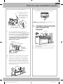
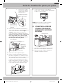
1. Levante el microondas,
inclínelo hacia adelante
y enganche las ranuras
del borde inferior
trasero en las cuatro
pestañas inferiores de
la placa de montaje.
2. Rote el frente del
horno contra la
parte inferior del
gabinete.
3.
Inserte un tornillo autoalineable a través del orificio
central superior del gabinete. Asegure temporalmente
el horno rotando el tornillo al menos dos giros
completos después de que se encajaron las
roscas. (Se ajustará por completo posteriormente).
Asegúrese de mantener el cable de alimentación
tenso. Tenga cuidado de no apretar el cable,
especialmente cuando instala el microondas a
nivel de la parte inferior del gabinete.
Cabinet Front
Filler Block
Microwave Oven Top
Self-Aligning Screw
Equivalent to
Depth of
Cabinet Recess
Cabinet Bottom Shelf
Equivalente a
la profundidad
del hueco del
gabinete
Estante inferior del gabinete
Parte superior del horno de microondas
Frente del gabinete
Bloque de relleno
Tornillo autoalineable
4. Sujete el microondas al gabinete superior.
5. Inserte los 2 tornillos autoalineables a través de la
parte inferior del gabinete y, si se utilizaron, a través
de los bloques de relleno en la parte superior externa
de la unidad. (Observe la ilustración de arriba)
Continúe sosteniendo la unidad hasta que ambos
tornillos estén insertados y encajados con al menos
dos giros completos y, luego, ajuste completamente
los dos tornillos hasta que la unidad esté segura.
6. Instale los filtros de grasa. Para obtener
instrucciones, consulte el manual del propietario
incluido con el microondas.
NOTA: Para los modelos con filtros de grasa
instalados, no necesita instalar un filtro.
E. CONECTAR LA RED DE
CONDUCTOS PARA EL
EXTRACTOR SUPERIOR
EXTERNO
House Duct
Conducto de la casa
1. Extienda el conducto de la casa hacia abajo
para conectarlo al adaptador del extractor.
2. Selle las juntas del conducto del extractor
utilizando cinta para conductos.
ME21K6000AS_AA_DE68-04108C-00_MES.indd 17 5/20/2016 5:06:50 PM

18
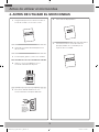
Antes de utilizar el microondas
1. Asegúrese de que el horno de microondas se
instaló de acuerdo con las instrucciones.
2. Quite todo el material de embalaje del horno
de microondas.
3. Instale el plato giratorio y el aro en la cavidad.
4. Vuelva a colocar el fusible de la casa o
encienda nuevamente el disyuntor.
Insure proper
ground exists
before use
5. Enchufe el cable de alimentación a un
tomacorriente de 15 amperes dedicado.
Insure proper
ground exists
before use
Asegúrese de
que exista una
conexión a tierra
adecuada antes de
utilizar el horno de
microondas.
6. Lea el manual del propietario.
7. Conserve las instrucciones de instalación
para que puedan ser consultadas por el
inspector de su localidad.
4. ANTES DE UTILIZAR EL MICROONDAS
ME21K6000AS_AA_DE68-04108C-00_MES.indd 18 5/20/2016 5:06:50 PM

19
Notas
ME21K6000AS_AA_DE68-04108C-00_MES.indd 19 5/20/2016 5:06:50 PM

DE68-04108C-00
ME21K6000AS_AA_DE68-04108C-00_MES.indd 20 5/20/2016 5:06:50 PM
-
 1
1
-
 2
2
-
 3
3
-
 4
4
-
 5
5
-
 6
6
-
 7
7
-
 8
8
-
 9
9
-
 10
10
-
 11
11
-
 12
12
-
 13
13
-
 14
14
-
 15
15
-
 16
16
-
 17
17
-
 18
18
-
 19
19
-
 20
20
-
 21
21
-
 22
22
-
 23
23
-
 24
24
-
 25
25
-
 26
26
-
 27
27
-
 28
28
-
 29
29
-
 30
30
-
 31
31
-
 32
32
-
 33
33
-
 34
34
-
 35
35
-
 36
36
-
 37
37
-
 38
38
-
 39
39
-
 40
40


Samsung ME21K6000AS/AA-01 Guía de instalación
- Categoría
- Microondas
- Tipo
- Guía de instalación
- Este manual también es adecuado para
En otros idiomas
Documentos relacionados
Otros documentos
-
Yes ME11CB751012 Guía de instalación
-
-
Dacor DMO30U970S Guía de instalación
-
Kenmore 40185043210 Guía de instalación
-
Hotpoint RVM1535DMCC Manual de usuario
-
GE Profile EMO3000HBB Guía de instalación
-
Hotpoint RVM1625SJ Manual de usuario
-
GE JVM1631WK Guía de instalación
-
GE Profile JVM1750DMWW Manual de usuario
-