
Installation Instructions
Instrucciones de instalaci6n
EngJish / Espa_oJ
Models / Modelos : 401.8504% 85143
I(e
@ @
¢ ::::,color numbe_} nOmero de color
P/N DE68-03806A
Sears Brands Management Corporation,
Hoffman Estates, IL 60179 USA
www.kenmore.com
www.sears.com

OF
CONTE TS
iMPORTANT SAFETY iNSTRUCTiONS ................. 3
Electrical Requirements ............................ 3
Electrical safety instructions ........................ 3
BEFOREYOU BEGIN.............................. 4
Hood Exhaust ................................... 4
Damage - Shipment/Installation .................... 6
Parts Included ................................... 6
Tools you will need ............................... 7
Mounting Space ................................. 7
iNSTALLATiONS ................................. 8
Placement of the Mounting Plate .................... 8
Installation Types (choose A, B or C) ................ 1 1
A. Recirculating (non-vented ductless) ............... 1 2
B. Outside Top Exhaust (Vertical Duct) ............... 14
C. Outside Back Exhaust (Horizontal duct) ............ 1 6
READ THESE iNSTRUCTiONS COMPLETELY AND
CAREFULLY.
* iMPORTANT - Save these instructions for local
inspector's use.
* IMPORTANT - Observe all governing codes and
ordinances.
* Note to installer - Be sure to leave these instructions
with the Consumer.
* Note to Consumer - Keep these instructions for future
reference,
* Skill level - Installation of this appliance requires basic
mechanical and electrical skills.
* Proper installation is the responsibility of the installer.
Product failure due to improper installation is not
covered under the Warranty.
BEFOREYOU USEYOUR MICROWAVE ............... 17

I SA ETYI
This product requires a three-prong grounded outlet. The
installer must perform a ground continuity check on the power
outlet box before beginning the installation to insure that the
outlet box is properly grounded. If not properly grounded, or
if the outlet box does not meet electrical requirements noted
(under ELECTRICAL REQUIREMENTS), a qualified electrician
should be employed to correct any deficiencies.
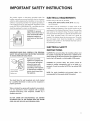
CAUTION: For personal
safety, remove house fuse or
open circuit breaker before
beginning instalJation to
avoid severe or fatal shock
injury.
IMPORTANT=PLEASE READ CAREFULLY. FOR PERSONAL
SAFETY, THIS APPLIANCE MUST BEPROPERLY GROUNDED
TO AVOID SEVERE OR FATAL SHOCK.
ground exists
before use
The power cord of this
appliance is equipped with
a three=prong (grounding)
pJugwhich mates with
a standard three-prong
(grounding) wall receptacle
to minimize the possibility of
electric shock hazard from
this appJiance.
ELECTRICAL REQUIREMENTS
Product rating is 120 volts AC, 60 Hertz,
" 85042, 85043, 85044, 85046, 85049, 85|43:13.5 arnps
and 1.5 kilowatts.
This product must be connected to a supply circuit of the
proper voltage and frequency. Wire size must conform to the
requirements of the National Electrical Code or the prevailing
local code for this kilowatt rating. The power supply cord
and plug should be brought to a separate 20 ampere branch
circuit single grounded outlet. The outlet box should be
located in the cabinet above the microwave oven. The outlet
box and supply circuit should be installed by a qualified
electrician and conform to the National Electrical Code or
the prevailing local code.
ELECTRICAL SAFETY
INSTRUCTIONS
CAUTION: For personal safety, the mounting surface must
be capable of supporting the cabinet load, in addition to the
added weight of this 59 pound product, plus additional oven
loads of up to 50 pounds or a total weight of 109 pounds.
CAUTION: For personal safety, this product cannot be
installed in cabinet arrangements such as an island or a
peninsula, it must be mounted to BOTH a top cabinet AND
a waft.
NOTE: For easier installation and personal safety, it is
recommendedthat two peopJeinstalJthisproduct.
You should have the wall receptacle and circuit checked
by a qualified electrician to make sure the receptacJe is
properJy grounded.
Where a standard two=prong wall receptacle isencountered,
it is very important to have it repJaced with a properJy
grounded three=prong waft receptacJe, instalJed by a
qualified eJectrician.
DO NOT, UNDER ANY CIRCUMSTANCES, CUT, DEFORM
OR REMOVE ANY OF THE PRONGS FROM THE POWER
CORD. DO NOT USE WiTH AN EXTENSION CORD.

YO I
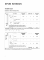
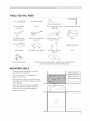
HOOD EXHAUST
Outside tap exhaust (example only_
The following chart describes an example of one possible ductwork installation.
DUCT PIECES EQUIVALENT EQUIVALENT
LENGTH x NUMBER USED = LENGTH
Roof Cap 24 Ft. x (1) = 24 Ft.
12 Ft. Straight Duct (6"
12 Ft. x (1) -- 12 Ft.
Round)
5 Ft. x (1) -- 5 Ft.
Rectangular-to-Round
_m Transition Adaptor*
Equivalent lengths of duct pieces are based on actual tests
and reflect requirements for good venting performance with
any vent hood. Total Length = 41 Ft.
* iMPORTANT: If a rectangular-to-round transition adaptor is used, the bottom corners of the damper will have to be cut to
fit, using the tin snips, in order to allow free movement of the damper.
Outside back exhaust (example only)
The following chart describes an example of one possible ductwork installation.
EQUIVALENT EQUIVALENT
(,_ DUCT PIECES LENGTH x NUMBER USED = LENGTH
Roof Cap 40 Ft. x (1) -- 40 Ft.
_ 3 Ft. Straight Duct
(31/4" x 10" 3 Ft. x (1) -- 3 Ft.
Rectangular)
Elbow 10 Ft. x (2) -- 20 Ft.
90 °
Equivalent lengths of duct pieces are based on actual tests
and reflect requirements for good venting performance with
any vent hood. Total Length = 63 Ft.
NOTE: For back exhaust t care should be taken to align exhaust with space between studst or wall should be prepared at the
time it is constructed by leaving enough space between the wall studs to accommodate exhaust.
4

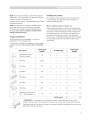
NOTE: If you need to install ducts, note that the total duct
length of 31/_" x 10" rectangular or 6" diameter round duct
should not exceed 140 equivalent feet.
Outside ventilation requires a HOOD EXHAUST DUCT. Read
the following carefully.
NOTE: It is important that venting be installed using the
most direct route and with as few elbows as possible.
This ensures clear venting of exhaust and helps prevent
blockages. Also, make sure dampers swing freely and
nothing is blocking the ducts.
EXHAUST CONNECTION:
The hood exhaust has been designed to mate with a
standard 31/_" x 10" rectangular duct.
If a round duct is required, a rectangular-to-round transition
adaptor must be used. Do not use less than a 6" diameter
duct.
MAXIMUM DUCT LENGTH:
For satisfactory air movement, the total duct length of 31/_''
x 10" rectangular or 6" diameter round duct should not
exceed 140 equivalent feet.
Elbows, transitions, wall and roof caps, etc.,
present additional resistance to airflow and are equivalent
to a section of straight duct which is longer than their actual
physical size. When calculating the total duct length, add
the equivalent lengths of all transitions and adaptors plus
the length of all straight duct sections. The chart below
shows you how to calculate total equivalent ductwork length
using the approximate feet of equivalent length of some
typical ducts.
EQUIVALENT EQUIVALENT
DUCT PIECES x NUMBER USED =
LENGTH LENGTH
Rectangular-to-Round 5 Ft. x ( ) : Ft.
Transition Adaptor S
Wall Cap 40 Ft. x ( ) : Ft.
90 ° Elbow 10 Ft. x ( ) : Ft.
45 ° Elbow 5 Ft. : Ft.
( )
X
Elbow 25 Ft. x ( ) : Ft.
90 °
Elbow 5 Ft. x ( ) : Ft.
45 °
Roof Cap 24 Ft. x ( ) : Ft.
1 Ft. x ( ) : Ft.
Straight
Duct 6" Round or
31A" x 10" Rectangular
Total Ductwork = Ft.
iMPORTANT: If a rectangular-to-round transition adaptor is used, the bottom corners of the
damper will have to be cut to fit, using the tin snips, in order to allow free movement of the damper.
Equivalent lengths of duct pieces are based on actual tests and reflect requirements for good venting
performance with any vent hood.

DAMAGE - SHIPMENT/INSTALLATION
* if the unit is damaged in shipment, call the store where the unit was purchased_ or 1-800-4-MY-HOME ®.
* if the unit is damaged by the custemer, repair or replacement is the responsibility of the customer.
* if the unit is damaged by the installer (if other than the customer), repair or replacement must be made by
arrangement between customer and installer.
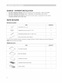
PARTS iNCLUDED
Hardware packet
PART QUANTITY
Wood Screws (1/_,,x 2") 1
_:::::_:_:::::_ Toggle Bolts (and wing nuts) (3/16" x 3") 2
/
Self-aligning Machine Screws (_/_"-28 x 33¼") 2
Nylon Grommet (for metal cabinets) 1
You will find the installation hardware contained in a packet with the unit. Check to make sure you have all these parts.
NOTE: Some extra parts are included.
Additional parts
PART QUANTITY
Top Cabinet Template 1
Rear Wall Template 1
installation instructions 1
Separately Packed Grease Filters 1
Exhaust adaptor 1
6

TOOLSYOU WILLNEED
#1 and #2 Phillips
screwdriver
Tin snips (for cutting
damper, if required)
Safety goggles
Pencil
Scissors (to cut template, if
necessary)
<
Saw (saber, hole or keyhole)
Ruler or tape measure and
straight edge
Electric drill with 3/16", I/2"
and 5/8" drill bits
Stud finder or Hammer
(optional)
Carpenter square (optional)
Gloves
Level
Duct and masking tape Filler blocks or scrap wood pieces, if needed for top cabinet spacing
(used on recessed bottom cabinet installations only)
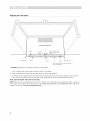
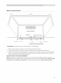
MOUNTING SPACE
* The space between the cabinets must be 30"
wide and free of obstructions.
* This microwave oven is for installation over
ranges up to 30" wide.
* If you are going to vent your microwave oven to
the outside, see Hood Exhaust Section for exhaust
duct preparation.
* When installing the microwave oven beneath
smooth fiat cabinets be careful to follow the
instructions on the top cabinet template for
power cord clearance.
5 _
Bottom Surface Of
cabinet needs to be
3011°[ more from
the cooking surface.
/
7

i STALLATIONS
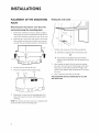
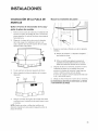
PLACEMENTOF THEMOUNTING
PLATE
Removing the microwave oven from the
carton!removina the mounting plate
1. Remove the installation instructions, Exhaust adaptor,
filters, glass tray and the small hardware bag. Do not
remove the Styrofoam protecting the front of the oven.
2. Fold back all 4 carton flaps fully against carton sides.
Then carefully roll the oven and carton over onto the
top side. The oven should be resting in the Styrofoam.
Carton
Styrofoam
3.
4.
Pull the carton up and off the oven.
Remove and properly discard plastic bags.
Screws
Screws
_1 Mounting
Plate
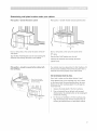
2.
Find the studs, using one of the following methods:
_i Stud finder-amagnetic _e;ice Which locate;
OR
a hammer t° tap lightly across the mounting i
_i!! ind!cate a stud
After locating the stud(s), find the center by probing
the wall with a small nail to find the edges of the stud.
Then place a mark halfway between the edges. The
center of any adjacent studs should be 16" or 24" from
this mark.
3. Draw a line down the center of the studs.
THE MICROWAVE MUST BE CONNECTED TO AT LEAST
ONE WALL STUD.
5. Remove the 2 screws from the mounting plate. This
plate will be used as the rear wall template and for
mounting.
NOTE: You will have to reuse two screws in original Ioction
of outcase after removing mounting plate.
8

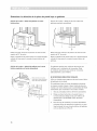
Determining wall plate location under your cabinet
Plate position - beneath fiat bottom cabinet
1/2"
Draw a vertical line on the wall at the center of the 30"
wide space.
Tape the Rear Walt Template onto the wall matching the
centerline and touching the bottom of the cabinet.
Plate position - beneath recessed bottom cabinet with
front overhang
Plate position - beneath framed recessed cabinet bottom
Draw a line on the back
wall equal to the depth of
the front overhang•
30" to Cooktop 3.
f
30" to Cooktop
Draw a vertical line on the wall at the center of the
30" space.
Tape the Rear Wall Template onto the wall
matching the centertine and touching the bottom
cabinet frame.
Your cabinets may have decorative trim that interferes with
the microwave installation. Remove the decorative trim to
install the microwave properly and to make it level.
THE MICROWAVE MUST BE LEVEL.
Use a level to make sure the cabinet bottom is level.
If the cabinets have a front overhang onlyt with no back
or side frame t install the mounting plate down the same
distance as the front overhang depth. This will keep the
microwave level.
1. Measure the inside depth of the front overhang.
2. Draw a horizontal line on the back wall an equal
distance below the cabinet bottom as the inside depth
of the front overhang.
For this type of installation with front overhang only,
align the mounting tabs with this horizontal line, not
touching the cabinet bottom as described in Step D.
9

Aligning the wall plate
REAR WAL_TEMPLATE
Draw a Vertical Line on
Area A Centerllne Wall from Center of Top
notches "_ _*_---- Cabinet
_OoOoOoOoOoO _ ,OoOoOeOoOoOoO
7
Hodzontal Une Area E Horizontal Une
Hole C Hole B
Draw a Horizontal line on wall from bottom of
"Rear Wall Template".
CAUTION: Wear gloves to avoid cutting fingers on sharp edges.
1. Draw a Vertical line on the wall at the center of the 30" wide space.
2. Draw a Horizontal line on the wall along the bottom of "Rear Wall Template".
3. Drill 5/8" holes for toggle bolts on 3 locations (Hole A, Hole B, Hole C) but if the location of hole is same as that of
stud, drill a 3/16" hole for wood screw. In other words, toggle bolt can not be used at the location of stud.
NOTE: DO NOT MOUNT THE PLATE AT THiS TIME.
NOTE: Holes A, Band C are inside area E. If none of A, B and C is in a stud, find a stud somewhere in area E and draw a
forth circle to line up with the stud. It is important to use at least one wood screw mounted firmly in a stud to support the
weight of the microwave. Set the mounting plate aside.
10

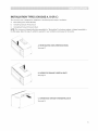
iNSTALLATiON TYPES (CHOOSE A, B OR C)
This microwave oven is designed for adaptation to the following three types of ventilation:
A. Recirculating (Non-Vented Ductless)
B. Outside Top Exhaust (Vertical Duct)
C. Outside Back Exhaust (Horizontal Duct)
NOTE: This microwave is shipped after being assembled for "Recirculating'. And exhaust adaptor is shipped assembled to
the filter-upper. Select the type of ventilation required for your installation and proceed to that section.
A. RECIRCULATING (NON-VENTED DUCTLESS)
See page 12
\
\
B. OUTSIDE TOP EXHAUST (VERTICAL DUCT)
See page 14
C. OUTSIDE BACK EXHAUST (HORIZONTAL DUCT)
See page16

A. RECIRCULATING (NON-VENTED DUCTLESS)
iNSTALLATiON OVERVIEW
A1. Attach mounting plate to wall
A2. Prepare top cabinet
A3. Mount the microwave oven
Attach the plate to the wall using toggle bolts. At least one
wood screw must be used to attach the plate to a wall stud.
1. Remove the toggle wings from the bolts.
2. Insert the bolts into the mounting plate through the hales
designated to go into drywall and reattach the toggle wings
to 3¼- onto each bolt.
To use toggle barfs:
Spacing for Toggles More Than Wall
._ ___,._kness
i
i Toggle Wings
Mounting
Plate
,O
3. Place the mounting plate against the wall and insert the
toggle wings into the holes in the wall to mount the plate.
NOTE: Before tightening toggle bolts and wood screw,
make sure to line up bottom line of the Mounting plate
with Horizontal line of "Rear wall Template" and then the
Mounting plate is properly centered under the cabinet.
CAUTION: Be careful to avoid pinching fingers between the
back of the mounting plate and the wall.
4. Tighten all bolts. Pullthe plate away from the wall to help
tighten the bolts.
A2. Use top cabinet template for
preparation of top cabinet
You need to drill holes for the top support screws and a hole
large enough for the power cord to fit through.
• Read the instructions on the TOP CABINET TEMPLATE.
• Tape it underneath the top cabinet.
• Drill the holes, following the instructions on the TOP
CABINET TEMPLATE.
CAUTION: Wear safety goggles when drilling holes in the
cabinet bottom.
12

A3. Mount the microwave oven
FOR EASIER INSTALLATION AND PERSONAL SAFETY,
WE RECOMMEND THAT TWO PEOPLE INSTALL THiS
MICROWAVE OVEN.
IMPORTANT." Do not grip or use handle during installation.
NOTE: If your wall cabinet is metal, use the nylon grommet
around the power cord hole to prevent cutting of the cord.
NOTE: We recommend using filler blocks if the cabinet has
a front overhang.
IMPORTANT: if filler blocks are not used, case damage
may occur from over tightening screws.
NOTE: When mounting the microwave oven, thread
power cord through hole in bottom of top cabinet.
Keep it tight throughout Steps 1-3. Do not pinch
cord or lift oven by 1. Lift microwave, tilt it
pulling cord.
forward, and hook
slots at back bottom
edge onto four lower
tabs of mounting
plate.
4. Attach the microwave oven to the top cabinet.
Cabinet Front
Cabinet Bottom Shelf
Filler Block
to Depth
of Cabinet Recess
gnlngScrew
Microwave Oven Top
Insert 2 self-aligning screws through outer top cabinet holes.
Turn two full turns on each screw.
6. Tighten the outer two screws to the top of the microwave
oven. (While tightening screws, hold the microwave oven in
place against the wall and the top cabinet.)
2. Rotate front of oven
up against cabinet
bottom.
3. Insert a self-aligning screw through top center cabinet hole.
Temporarily secure the oven by turning the screw at least
two ful! turns after the threads have engaged. (It will be
completely tightened later.) Be sure to keep power cord
tight. Be careful not to pinch the cord, especially when
mounting flush to bottom of cabinet.
/
7. Install grease filters. See the Owner's Manual packed with
the microwave.
13

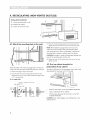
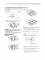
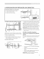
B. OUTSIDE TOP EXHAUST (VERTICAL DUCT)
B1. Adapting microwave blower For outside
top exhaust
1. Remove and save screw
2. Lift up the
that holds blower plate to / blower plate.
microwave. J
Blower Plate
Back of
"'""%_ Microwave
Screw
3. Carefully pull out the blower unit. The wires will extend far
enough to allow you to adjust the blower unit.
CAUTION: Do not touch blade of blower to prevent
cracking and breaking. Hold outer case when the blower is
removed and re-installed.
4. Roll the blower unit 90 ° so that fan blade openings are
facing toward the top of the microwave.
BEFORE: Fan Blade Openings
Facing Forward
AFTER: Fan Blade Openings
Facing Upward
5. Place the blower unit back into the opening.
CAUTION: Do not pull or stretch the blower unit wiring.
Make sure the wires are not pinched.
6. Lower the blower plate into original position and secure
blower unit to microwave with the screw.
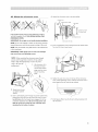
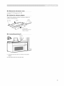
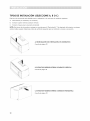
B2. Installation procedure For exhaust
adaptor and proper damper operation
check
]. Remove and save screw from the panel-outer
Roll _.Z1_
Exhaust Adaptor and Damper is
shipped assembled to the filler-upper.
2. Slide exhaust adaptor following the instructions show in
diagram.
3. Make sure tape securing damper is removed and damper
pivots easily before mounting microwave.
4. Lift damper and Re-screw at same location as (1).
* You will need to make adjustments to assure proper
alignment with your house exhaust duct after the microwave
is installed.
14

B3. Mount the microwave oven
see page 12_13. (Proceed on AI_A3)
B4. Adjust the exhaust adaptor
Open the top cabinet and adjust the exhaust adaptor to
connect to the house duct.
Back of
Blower-Plate Damper Microwave
__o_ te___sBtadekthe Exhaust
Adaptor as Needed
B5. Connecting ductwork
House Duct
|. Extend the house duct down to connect to the exhaust
adaptor.
2. Seal exhaust duct joints using duct tape.
15

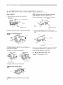
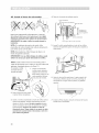
C. OUTSIDEBACK EXHAUST (HORIZONTAL DUCT)
C1. Adapting microwave blower for outside Makesure thewiresare notpinched.
back exhaust NOTE: The blower unit exhaust openings should match
exhaust openings on rear of microwave oven.
1.
6. Secure the blower unit to the microwave with the screw.
Remove and save screw that holds blower Plate to
microwave.
Blower motor screw
2. Lift up the Blower Plate.
Blower motor
of
Microwave
_%_ Back of
Microwave
Blower motor screw
Blower-Plate
From the Mounting Plate
screw
3. Carefully pull out the blower unit. The wires will extend far
enough to allow you to adjust the blower unit.
BEFORE: Fan Blade Openings Facing
Forward d B
End A
CAUTION: Do not touch blade of blower to prevent
cracking and breaking. Hold outer case when the blower is
removed and re-installed.
4. Rotate blower unit counterclockwise 180°.
7. Attach the exhaust adaptor to the rear of the oven by
sliding it into the guides at the top center of the back of the
oven.
Adaptor
_/ _ Back of
Gulde From Blower motor screw (after attached the
exhaust adaptor)
Pushin securely until it is in the lower locking tabs. Take care
to assure that the damper hinge is installed so that it is at
the top and that the damper swings freely.
Before Rotation After Rotation
\
I
Back of Microwave
Back of Microwave
C2. Mount the microwave oven
see page 12-13 (proceed on A1-A3)
5. Place the blower unit back into the opening.
AFTER: Fan Blade Openings Facing
Back
End B
CAUTION: Do not pull or stretch the blower unit wiring.
16

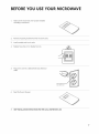
YO YO ICROWAV
1. Make sure the microwave oven has been installed
according to instructions.
2. Remove all packing material from the microwave oven.
3. Install turntable and ring in cavity.
4. Replace house fuse or turn breaker back on.
5. Plug power cord into a dedicated 20 amp electrical
outlet.
Insure proper ground
exists before use
6. Read the Owner's Manual.
7. KEEP INSTALLATION INSTRUCTIONS FOR THE LOCAL INSPECTOR'S USE.
17

NOTE

iNSTRUCCIONES DE SEGURiDAD iMPORTANTES ....... 20
Requisitos el_ctricos ............................. 20
Instrucciones de seguridad el_ctrica ................ 20
ANTES DE COMENZAR .......................... 21
Extractor de campana ........................... 21
Da_os - Envio/Jnstalaci6n ........................ 23
Piezas incluidas ................................ 23
Herramientas necesarias ......................... 24
Espacio de instalaci6n ........................... 24
INSTALACiONES................................ 25
Colocaci6n de la placa de montaje ................. 25
Tipos de instalaci6n (seleccione A, B o C) ............ 28
A. Recirculaci6n (sin venfilaci6n, sin conductos) ......... 29
B. Extractor superior externo (conducto vertical) ....... 31
C. Extractor trasero externo (conducto horizontal) ..... 33
LEA ESTAS INSTRUCCIONES EN SU TOTALIDAD Y
CUIDADOSAMENTE.
* IMPORTANTE - Guarde estas instrucciones para uso
del inspector local.
* IMPORTANTE - Cumpla todos los c6digos y
ordenanzas vigentes.
" Nora para el instalador - AsegOrese de de]arle estas
instrucciones al Cliente..
" Nora al Consumidor - Conserve estas instrucciones
para consultas futuras.
* Nivel de especializaci6n - La instataci6n de este
artefacto requiere conocimientos mec6nicos y
el_ctricos b6sicos.
La instalaci6n adecuada es responsabilidad del
instatador,
" La fatla del producto debido a una instalaci6n
inadecuada no est6 cubierta por la Garantfa.
ANTES DE UTiLiZAR ELMiCROONDAS .............. 34
19

I
I
S I
Este producto requiere un tomacorriente con conexi6n
a tierra de tres pines. El instalador debe controlar la
continuidad de conexi6n a tierra en ta caja de distribuci6n
el_ctrica antes de comenzar la instalaci6n para asegurar
que ta caja de distribuci6n est_ correctamente conectada
a tierra. Si no est_ conectada a tierra como correspondet o
si la caja de distribuci6n el_ctrica no cumple los requisitos
el6ctricos seSalados (en REQUISITOS ELECTRICOS), debe
contratarse a un electricista calificado para corregir
cualquier deficiencia.
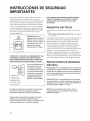
PRECAUCI6N: Para su
seguridad personal, quite ei
fusible de la casa o abra el
disyuntor antes de comenzar
la instalaci6n para evitar
lesiones por descargas
el_ctricas graves o fatales.
IMPORTANTE = POR FAVOR LEA DETENIDAMENTE. PARA
SU SEGURIDAD PERSONAL, ESTEARTEFACTO DEBE
ESTARCORRECTAMENTE CONECTADO A TIERRA PARA
EVITAR DESCARGAS ELECTRICAS GRAVES O FATALES.
AsegOrese de
que existe una
conexi6n a tierra
adecuada antes
de utitizar el homo
Elcable de alimentaci6n de
este artefacto cuenta con
un enchufe de tres pines
(con conexi6n a tierra) clue
se conecta al tomacorriente
de tres pines (con conexi6n
a tierra) para minimizar la
posibilidad de descargas
el_ctricas de este artefacto.
de microondas
BAJO NINGUNA CIRCUNSTANCIA CORTE, DEFORME
O QUITE CUALQUIERA DE LOS PINES DEL CABLE DE
ALIMENTACI6N. NO LO UTILICE CON UN CABLE
ALARGADOR.
REQUISITOS EL :CTRICOS
La potencia de servicio del producto esde 120 voltios CA,
60 Hz.
85042, 85043, 85044, 85046, 85049, 85143:13.5 amperios
y 1.5kilovatios.
Este producto debe conectarse a un circuito de alimentaci6n
con el vottaje y la frecuencia adecuados. El tamaSo det
cable debe adecuarse a los requerimientos del C6digo
EI6ctrico Nacionat o el c6digo local vigente para esta
potencia de kilovatios. El cable de atimentaci6n el_ctrica
y el enchufe deben conectarse a un tomacorriente con
conexi6n a tierra Onico con circuito derivado de 20 amperes
separado. La caja de distribuci6n el&ctrica debe estar
ubicada en et gabinete arriba del horno de microondas. Un
electricista calificado debe instalar la caja de distribuci6n
el_ctrica y el circuito de alimentaci6n y _stos deben cumplir
con el C6digo El_ctrico Nacionat o el c6digo local vigente.
INSTRUCCIONES DE SEGURIDAD
ELECTRICA
PRECAUCI6N: Para su seguridad personal, la superflcie de
montaje debe ser capaz de soportar la carga del gabinete,
adem6s del peso agregado de este producto de 59 pound,
m6s las cargas adicionales del homo de hasta 59 pounds o
un peso total de 109 pounds.
PRECAUCI6N: Para su seguridad personal, este producto
no puede instalarse en dise_os de gabinetes tales como los
gabinetes tipo isla o peninsula. Debe instalarse TANTO en
un gabinete superior COMO en la pared.
Un electricista calificado debe veriflcar el tomacorriente
de pared y el circuito para asegurarse de clue el
tomacorriente tenga una conexi6n a tierra adecuada.
NOTA: Para una instalaci6n m6s sencilla y para su
seguridad personal, se recomienda que dos personas
instalen este producto.
Cuando exista un tomacorriente de pared de dos pines
est6ndar, es muy importante reemplazarlo por un
tomacorriente de pared de tres pines con conexi6n a tierra
adecuada, instalado por un electricista califlcado.
2O

A TS COM ZA
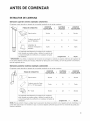
EXTRACTOR DE CAMPANA
Extractor superior externo (_jemplo solamente)
El siguiente cuadro describe un ejemplo de una posible instataci6n de la red de conductos.
PIEZA$ DE CONDUCTOS
de techo
Tapa
Conducto recto de 12
pies (6" Redondo)
Adaptador de
transici6n rectangular a
redondo*
LONGITUD CANTIDAD LONGITUD
X =
EQUIVALENTE UTILIZADA EQUIVALENTE
24 pies x (1) = 24 pies
12pies x (1) = 12 pies
5 pies x (1) = 5 pies
Las longitudes equivatentes de las piezas de los conductos
est6n basadas en pruebas reales y reflejan los requisitos de
un buen desempe_o de ventilaci6n con cuatquier campana
de ventilaci6n. Longitud total = 41 pies
* IMPORTANTE: Si se utitiza un adaptador de transici6n de rectangular a redondo_ las esquinas inferiores del regulador de
tiro de humo deber6n cortarse para encajar_ utilizando las tijeras para cortar metates, con el fin de permitir el movimiento
libre del regulador de tiro.
Extractor posterior externo (_emplo soiarnente)
El siguiente cuadro describe un ejemplo de una posible instataci6n de la red de conductos.
PIEZA$ DE CONDUCTOS
Tapa de techo
Conducto recto de 3 pies
(31A'' x 10" Rectangular)
LONGITUD CANTIDAD LONGITUD
X =
EQUIVALENTE UTILIZADA EQUIVALENTE
40 pies x (1) = 40 pies
3 pies (1) : 3 pies
90 o Codo 10 = 20
pies (2) pies
X
Las longitudes equivatentes de las piezas de los conductos
est6n basadas en pruebas reales y reflejan los requisitos de
un buen desempe_o de ventilaci6n con cuatquier campana de
ventilaci6n. Longitud total = 63 pies
NOTA: Para el extractor trasero_ se debe tener la precauci6n de alinear el extractor con el espacio entre los montantes t o la
pared debe prepararse en el momento en que se construye dejando suficiente espacio entre los montantes de pared para
colocar el extractor.
21

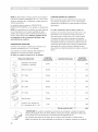
NOTA: Si debe instalar conductos, observe que la longitud
total de los conductos rectangutares de 3 1/_- x 10" o de los
conductos redondos de 6" de di_metro no debe superar los
140 pies equivalentes.
La ventilaci6n externa requiere un CONDUCTO DE
EXTRACTOR DE CAMPANA. Lea Io siguiente con detenimiento.
NOTA: Es importante que la ventitaci6n se instate utilizando
la ruta m_s directa y con ta menor cantidad de codos
posibles. Esto asegura la buena ventilaci6n del extractor y
ayuda a evitar obstrucciones. Adem_s, aseg6rese de que
_osreguladeres de tire se balanceen _ibremente V que
nada obstruya los conductos.
CONEXleN DEL EXTRACTOR:
El extractor de campana sedise_6 para coincidir con el
conducto rectangular de 3V_" x 10" est_ndar.
Si se necesita un conducto redondo, debe utilizarse un
adaptador de transici6n rectangular a redondo.
No utffice un conducto de menos de 6" de di_metro.
LONGITUD M._XIMA DEL CONDUCTO:
Para una rotaci6n de aire satisfactoria, la Iongitud total
del conducto rectangular de 3V_" x 10" o det conducto
redondo de 6" de di6metro no debe exceder los 140 pies
equivatentes.
Loscedes, transicienes, tapas de techo y pared, etc.,
presentan una resistencia adicionat al flujo de aire y son
equivalentes a una secci6n de conducto recto que es
m6s extensa que su tama_o fisico real. Cuando catcule
la tongitud total del conducto, agregue las longitudes
equivalentes de todas las transiciones y adaptadores m6s
la longitud de todas las secciones de conductos rectos. El
cuadro que sigue muestra c6mo calcular la longitud total
equivatente de la red de conductos utilizando los pies
aproximados de longitud equivatente de atgunos conductos
tfpicos.
LONGITUD LONGITUD
PIE'ZAS DE CONDUCTOS x CANTIDAD UTILIZADA =
EQUIVALENTE EQUIVALENTE
Adaptador de transici6n
rectangular a redondo _ 5 pies x ( ) : pies
Difusor de pared 40 pies x ( ) : pies
90 ° Codo 10 pies x ( ) : pies
-_ pies x ( ) pies
45
o
Codo 5
pies x ( ) pies
9O
o
Codo 25
pies x ( ) pies
45
o
Codo 5
Tapa pies x ( ) pies
de techo 24
1 pie x ( ) -- pies
Conducto recto redondo de
6" o rectangular de 3V_ x 10"
Red de conductos tota_ = pies
IMPORTANTE: Si se utiliza un adaptador de transici6n de rectangular a redondo, tas esquinas
inferiores del regulador de tiro de humo deber_n cortarse para encajar, utilizando las tijeras para
cortar metates, con el fin de permitir el movimiento libre det regulador de tiro.
Las longitudes equivalentes de las piezas de los conductos est_n basadas en pruebas reales y
reflejan los requisitos de un buen desempe_o de ventilaci6n con cuatquier campana de ventilaci6n.
22

DAI OS - ENVJO/INSTALACI6N
* Sila unidad se daRa en el envJo, comun[quese con la tJenda donde la compr6_ o con el 1-800-4-MY-HOME ®.
* Siel diente da_a la unidad, Ja reparacJ6n o eJ reempJazo es responsabilJdad deJ cJJente.
* Siel instalador dafia la unidad (en caso de que sea una persona distinta al ctiente), la reparaci6n o el reemplazo
deben reatizarse mediante un acuerdo entre el ctiente y el instalador.
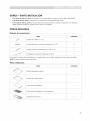
PIEZAS INCLUIDAS
Paquete de componentes
PIEZA CANTIDAD
Tornillos de madera (1/_,,x 2") 1
'i
_ii_',:::::_:_';::_ Tornitlos de fiador (y tuercas tipo mariposa)(3/_6" x 3") 2
/
/
Tornitlos mec6nicos autoatineables (1/_'-28 x 33¼") 2
Pasacables de naiton (para gabinetes de metal) 1
Encontrar6 los componentes de instataci6n en un paquete junto con ta unidad. Aseggrese de tenet todas estas piezas.
NOTA: Se inctuyen atgunas piezas adicionates.
Piezas adicionales
PIEZA CANTIDAD
Plantilta del gabinete superior 1
Plantilta de la pared trasera 1
Instrucciones de instalaci6n 1
Filtros de grasa embatados en forma separada 1
Adaptador deJ extractor 1
23

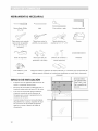
HERRAMIENTAS NECESARIAS
Destornitlador Phillips L6piz Cinta m_trica y regta Escuadra (opcionat)
#1y#2
Tijeras para cortar metales
(para cortar el regulador
de tiro de humo_ si es
necesario)
Gafas de seguridad
Tijeras (para cortar la
plantilta, si es necesario)
Sierra (tipo sable_ de
perforaci6n o de calar)
Taladro el_ctrico con
mechas de 3/16", 1/2" y 5/8"
Detector de montantes o
martillo (opcionat)
Guantes
Nivelador
Cinta adhesiva y para
conductos
Bloques de relleno o pedacitos de madera sobrantes_ si se necesitan para el espaciado del
gabinete superior (utilizados en instataciones de gabinete con parte inferior empotrada
ESPACIO DE INSTALACION
solamente)
Elespacio entre los gabinetes debe tener 30_ de
ancho y no presentar obstrucciones.
Este homo de microondas es adecuado para su
instalaci6n sobre estufas de hasta 30_ de ancho.
Si su horno de microondas tendr6 ventilaci6n
al exterio b consulte la secci6n Extractor de
Campana para conocer la preparaci6n de los
conductos del extractor.
Cuando instale et homo de microondas debajo
de gabinetes tisos y planos_ asegOrese de seguir
las instrucciones de la plantilla del gabinete
superior en cuanto at espacio del cable de
alimentaci6n.
I
L El b6rde infe!ia r
de! gabinete debe I
estar a 30!! o m6s
a upoi €!ede
CoccJ6n.
24

I STALACIONES
COLOCACION DE LA PLACA DE
MONTAJE
Quitar el homo de microondas de la caja/
quitar [a p[aca de rnontaje
1. Retire las instrucciones de instataci6n, el adaptador del
extractor t los filtros t ta bandeja de vidrio y la bolsa de
piezas peque_as. No quite el Styrofoam que protege el
frente del horno.
2. Pliegue las 4 solapas de la caja contra los laterales
de la caja. Luego con cuidado gire el homo y la
caja y ap6yelo sobre la parte superior. El homo debe
apoyarse sobre el Styrofoam.
Caja
Styrofoam
3. Tire la caja hacia arriba para separarta det horno.
4. Quite y deseche las bolsas de pl6stico de la manera
adecuada.
Tornillos
Tornillos
Placa de
montaje T
Buscar los rnontantes de pared
1.
2.
3.
Busque los montantes, utilizando uno de los siguientes
m_todos:
Ai Detector de montantes - un dispositivo magn_tico
0
Bi Utilice Un marti!lo para go!pear Suavemente la
Superficie de montaje hasta encontrar un sonido
s61ido.Esto indicar6 la ubicaci6n de un montante.
Despu_s de ubicar los montantes, encuentre el centro
sondeando la pared con un pequeSo clavo para
encontrar los bordes del montante. Luego haga una
marca a mitad de camino entre los bordes.
El centro de cualquier montante adyacente debe estar
a 16" o 24" de esta marca.
Dibuje una tfnea vertical en el centro de los montantes.
ELMICROONDAS DEBE ESTARCONECTADO AL MENOS
A UN MONTANTE DE PARED.
5. Quite los 2 tornillos de la placa de montaje. Esta placa
se utilizar6 como la plantilta de la pared trasera y para
el montaje.
NOTA: Tendr6 que volver a utilizar dos tornillos en ta
ubicaci6n original de la caja exterior despu_s de retirar la
placa de montaje.
25

iiiiiiiiiiiiiiiiiilliiiiiiiii!i!!!iiiiiiiiii!iii!ii¸ili!iiiiiiiiiiiill!i!iiiiiiiliiiiiiiiiiii¸ii_i_iili!!i!!!i!ii!!iii¸!ii!iii_!!i!!!!i!iiiii!i¸iiliil_i_iii_!!ii¸¸iiililililililililililililililililililililililililililililililililililililililililililililililililililililililililililililililililililililililililililililililililililililililililililililililililililililililililililililililililililililililililililililililililililililililililililililililililililililililililililililililililililililililililililililililililililililililililililililililililililililililililililililililililililililililililililililililililililililililililililililililililililililililililililililililililililililililililililililililililililililililililililililililililililililililililililililililililililililililililililililililililililililililililililililililililililililililililililililililililililililililililililililililililililililililililililililililililililililililililililililililililililililililililililililililililililililililililililililililililililililililililililililililililililililililililililililili
Deterrninar Ja ubicaci6n de Ja pJaca de pared bajo su gabinete
Posici6n de ta ptaca - debajo de la parte inferior delPosici6n de la pJaca - debajo deJ gabinete con parte
inferior pJana
i'
Dibuje una tinea vertical en ta pared en el centro de este
espacio de 30" de ancho.
Pegue la plantilla de ta pared trasera en ta pared haciendo
coincidir la Ifnea central y tocando la parte inferior del
gabinete.
Posici6n de la placa - debajo deJ gabinete con Ja parte
inferior ernpotrada con frente sobresaJiente
_- 30" a la estufa
gabinete empotrado ensamblado
Dibuje una tfnea vertical en la pared en el centro de este
espacio de 30" de ancho.
Pegue la plantitla de la pared trasera en la pared haciendo
coincidir ta linea central y tocando la parte inferior del
gabinete.
Sus gabinetes pueden tener motduras decorativas que
interfieren con ta instalaci6n del microondas. Quite
las motduras decorativas para instatar el microondas
adecuadamente y para nivelarlo.
ELMICROONDAS DEBE ESTAR NIVELADO.
Utilice un nivelador para asegurarse de que la parte inferior
del gabinete est_ nivelada.
Si los gabinetes tienen un frente sobresatiente solamente,
sin ninguna armaz6n trasera o lateral, instale la placa de
montaje a ta misma distancia que la profundidad det frente
sobresatiente. Esto mantendrc_ et microondas nivelado.
1. Mida la profundidad interior del frente sobresaliente.
2. Dibu_e una lfnea horizontal en ta pared trasera a
la misma distancia debajo de ta parte inferior del
gabinete que ta profundidad interior del frente
sobresatiente.
3. Para este tipo de instataci6n con frente sobresaliente
solamente, atinee las pesta_as de instalaci6n con esta
linea horizontal sin tocar la parte inferior del gabinete
como se describe en el Paso D.
26

Alinear la plata de pared
REAR WAL_TEMPLATE
Linea horizontal
Muescas de la Dibuje una linea vertical en [a
,_,rea A I_nea central pared desde el centro dei
x'_ i _r-_ superior
,!
_OoOoOoOoOoO _ _OoOoOeOoOoOoO
j,
_,rea E
Orificio C Orificlo B
Linea horlzontaI
Trace una I[nea horizontal en la pared desde de la
parte inferior de la "plantlila de la pared trasera",
PRECAUCI6N: Use guantes para evitar cortarse los dedos con los bordes fitosos.
1. Dibuje una Ifnea vertical en la pared en et centro de este espacio de 30" de ancho.
2. Trace una linea horizontal en la pared a 1olargo de la parte inferior de la "ptanfitta de la pared trasera".
3. Perfore orificios de 5/8" para tornitlos de fiador en 3 lugares (oriflcio A, orificio B y orificio C), pero si ta ubicaci6n del
orificio es la misma que la del montante, perfore un orificio de 3/16" para tornitlo de madera. Es decir, el tornitto de
fiador no se puede usar donde va ubicado el montante.
NOTA: NO INSTALE LA PLACA EN ESTEMOMENTO.
NOTA: Los oriflcios A, By C estc_ndentro del 6tea E. Si ni A ni B ni C est6n en un montante, encuentre un montante en
atguna parte del 6tea Ey dibuje un quinto cfrculo para alinearto con el montante. Es importante ufitizar al menos un tornilJo
de madera sujetado con flrmeza en un montante para soportar el peso del microondas. Aparte Ja placa de montaje.
27

iiiiii;iilliiiiiiiii!i!!!ii13!ii¸fIG!i!iiiiiiiliiiiiiiiiiii¸ii_i_iili!!i!!!i!ii!!iii¸!ii!iii_!!i!!!!i!iiiii!i¸iiliil_i_iii_!!ii¸¸iiililililililililililililililililililililililililililililililililililililililililililililililililililililililililililililililililililililililililililililililililililililililililililililililililililililililililililililililililililililililililililililililililililililililililililililililililililililililililililililililililililililililililililililililililililililililililililililililililililililililililililililililililililililililililililililililililililililililililililililililililililililililililililililililililililililililililililililililililililililililililililililililililililililililililililililililililililililililililililililililililililililililililililililililililililililililililililililililililililililililililililililililililililililililililililililililililililililililililililililililililililililililililililililililililililililililililililililililililililililililililililililililililililililililililililililili
TIPOS DE INSTALACI6N (SELECCIONE A, B O C)
Este horno de microondas est6 dise_ado para su adaptaci6n a los tres tipos de ventilaci6n siguientes:
A. Recirculaci6n (sin ventilaci6n, sin conductos)
B. Extractor superior externo (conducto vertical)
C. Extractor trasero externo (conducto horizontal)
NOTA: Este horno de microondas se entrega con montaje para la "Recirculaci6n". Y el adaptador del extractor se entrega
unido al relleno superior. Seleccione el tipo de ventilaci6n requerido para su instataci6n y avance a esa secci6n.
J
A. RECIRCULACION (SIN VENTILACION, SIN CONDUCTOS)
Consulte la p6gina 29
\
\
B. EXTRACTOR SUPERIOR EXTERNO (CONDUCTO VERTICAL)
Consulte la p6gina 3]
C. EXTRACTOR TRASERO EXTERNO (CONDUCTO HORIZONTAL)
Consulte la p6gina 33
28

A. RECIRCULACION (SIN VENTILACION, SIN CONDUCTOS)
DESCRIPCION GENERAL DE LA INSTALACI6N
A1. Sujete la placa de montaje a la pared
A2. Prepare el gabinete superior
A3. Instale el homo de microondas
Sujete la placa a la pared utilizando los tornitlos de fiador.
Se debe utitizar al menos un tornillo de madera para sujetar
la placa a un montante de pared.
1. Quite las mariposas de los tornillos.
2. Inserte los tornillos en la placa de montaje a trav_s de los
orificios designados para ingresar en el muro y vuelva a
colocar las mariposas a 3¼-en ¢ada tornillo.
Para utilizar tornillos de flador:
j Espaciado para estos tornillos mayor al grosor de la pared
i Mariposas
Placa
de _,_
montaje
- Pared
tornlilo
3. Coloque la placa de montaje contra la pared e inserte las
mariposas en los orificios de la pared para instalar la placa.
NOTA: Antes de ajustar los tornillos de fiador y el tornillo
de madera_ asegOrese de atinear ta lfnea de la parte
inferior de la ptaca de montaje con ta linea horizontal de
la "plantilla de la pared trasera" Yt asft la placa de montaje
quedar6 correctamente centrada debajo del gabinete.
PRIzCAUCi6N: Tenga cuidado de no agarrarse los dedos
entre la parte trasera de la placa de montaje y la pared.
4. Ajuste todos los tornillos. Separe la placa de la pared para
ajustar los tornillos.
A2. Utilice la plantilla del cjabinete
superior para la preparaci6n del gabinete
superior
Debe perforar oriflcios para los tornitlos de soporte superior
y un orificio Io suflcientemente grande para que pase el
cable.
* Lea las instrucciones en ta PLANTILLA DELGABINETE
SUPERIOR.
* P_gueta con cinta adhesiva debajo del gabinete
superior.
* Perfore los orificios, siguiendo las instrucciones de la
PLANTILLA DEL GABINETE SUPERIOR.
PRECAUCI6N: Use gafas de seguridad cuando haga
orificios en la parte inferior del gabinete.
29

iiiiiiiiiiiiiiiiiilliiiiiiiii!i!!!iiiiiiiiii!iii!ii¸ili!iiiiiiiiiiiill!i!iiiiiiiliiiiiiiiiiii¸ii_i_iili!!i!!!i!ii!!iii¸!ii!iii_!!i!!!!i!iiiii!i¸iiliil_i_iii_!!ii¸¸iiililililililililililililililililililililililililililililililililililililililililililililililililililililililililililililililililililililililililililililililililililililililililililililililililililililililililililililililililililililililililililililililililililililililililililililililililililililililililililililililililililililililililililililililililililililililililililililililililililililililililililililililililililililililililililililililililililililililililililililililililililililililililililililililililililililililililililililililililililililililililililililililililililililililililililililililililililililililililililililililililililililililililililililililililililililililililililililililililililililililililililililililililililililililililililililililililililililililililililililililililililililililililililililililililililililililililililililililililililililililililililililililililililililililililililililili
A3. JnstaJeeJ homo de microondas
PARA UNA INSTALACI6N M_.S SENCILLA Y PARA SU
SEGURIDAD PERSONAL, RECOMENDAMOS QUE DOS
PERSONAS INSTALEN ESTE HORNO DE N|ICROONDAS.
JMPORTANTE: No sujefe ni ufiJice la manija duranfe la
instalaci6n.
NOTA: Si su gabinete de pared es de metal t utilice
pasacabtes de nailon alrededor del cable de alimentaci6n
para evitar que se corte el cable.
NOTA: Recomendamos utitizar bloques de relleno si el
frente del gabinete sobresate.
IMPORTANTE: Si no se utiiizan bioques de reiieno, puede
da_arse _a carcasa por ajusfar demasiado _o_ forniHo_.
NOTA: Cuando instale el homo de microondas_ pase el
cable de alimentaci6n pot el oriflcio en la parte inferior del
gabinete. Mant@ngato tenso en los Pasos 1-3.
No apriete el cable 1. Levante el microondas,
ni levante el homo inclinelo hacia adelante y
tirando del cable, enganche las ranuras del
borde inferior trasero en las
cuatro pesta_as inferiores
de la placa de monta]e.
2. Rote el frente del homo contra
la parte inferior del gabinete.
3. inserte un tornillo autoalineable a trav_s del orifieio central
superior del gabinete. Asegure temporalmente el homo
rotando el tornillo al menos dos glros compietos despu_s
de que se enca]aron las roscas. (Se ajustar6 por completo
posteriormente). Aseg,_rese de mantener el cable de
alimentaci6n tenso. Tenga cuidado de no apretar el cable,
especialmente cuando instala el microondas a nivel de la
parte inferior del gabinete.
4. Suiete el microondas al gabinete superior.
Frent÷ del gablnete
gabinet÷
Bloque de rell÷no
J_hEpluival÷nt÷ a la
rofundidad d÷l
eco del gabinete
Parte superior del homo de microondas
inserte 2 tornillos autoalineables a travSs de los orificios
exteriores del gabinete superior. D_ dos giros completos a
cada tornillo.
6. Ajuste los dos tornillos exteriores a la parte superior del
microondas. (Mientras ajusta los tornillos, mantenga el
microondas en su lugar contra la pared y el gabinete
superior).
7. Instale los filtros de grasa. Consulte el Manual del Usuario
incluido con el microondas.
3O

B. EXTRACTOR SUPERIOR EXTERNO
B1. Adaptar el ventilador del microondas
para el extractor superior externo
Quite y guarde el tornillo 2. Levante la
que suieta la plata del _ plata del
venfilador al microondas.
ventJlador.
\
Placa del ventilador
Tornillo
Parteposteriordet
microondas
(CONDUCTO VERTICAL)
DESPUES: Aberturas de las aspas del ventilador hacia
arriba
5. Coloque la parte trasera de la unidad de venfilador en la
abertura.
3. Retire con cuidado la unidad de venfilador. Los cables se
extender6n Io sufidente para permifirle ajustar la unidad de
venfilador.
PRECAUCI6N: No toque las aspas det ventilador para
evitar que sequiebren y se rompan. Sostenga la carcasa
exterior cuando se retire y se vuelva a instatar.
4. Rote la unidad de venfilador 90 o para que las aberturas
de las aspas del venfilador miren a la parte superior del
microondas.
ANTES: Aberturas de las aspas del ventilador hacia
adelante
Rote -_
PRECAUCI6N: No tire ni extienda el cableado de la unidad de
ventilador. Aseg6rese de que los cables no queden apretados.
6. Baie la placa del ventilador a su posici6n original y suiete la
unidad de ventilador al microondas con el tornillo.
B2. Procedimiento de instalaci6n para el
adaptador del extractor y verificaci6n de
funcionamiento adecuado del reguiador de
tiro de humo
1. Quite y guarde el tornillo del panel exterior
Et adaptador dei extractor y el regulador de tiro de
humo se entregan unidos al reileno superior.
2. Deslice el adaptador del extractor siguiendo las
instrucciones que se muestran en el diagrama.
3. Aseg6rese de quitar la cinta adhesiva que ilia el regulador
de tiro y de que el regulador de tiro se balancee con
facilidad antes de instalar el microondas.
4. Levante el regulador de tiro y vuelva a atornillarlo en la
misma posici6n que (1).
* Deber6 hater aiustes para asegurar la correcta alineaci6n
con el conducto del extractor de su casa despu_s que el
microondas est_ instalado.
31

iiiiiiiiiiiiiiiiiilliiiiiiiii!i!!!iiiiiiiiii!iii!ii¸ili!iiiiiiiiiiiill!i!iiiiiiiliiiiiiiiiiii¸ii_i_iili!!i!!!i!ii!!iii¸!ii!iii_!!i!!!!i!iiiii!i¸iiliil_i_iii_!!ii¸¸iiililililililililililililililililililililililililililililililililililililililililililililililililililililililililililililililililililililililililililililililililililililililililililililililililililililililililililililililililililililililililililililililililililililililililililililililililililililililililililililililililililililililililililililililililililililililililililililililililililililililililililililililililililililililililililililililililililililililililililililililililililililililililililililililililililililililililililililililililililililililililililililililililililililililililililililililililililililililililililililililililililililililililililililililililililililililililililililililililililililililililililililililililililililililililililililililililililililililililililililililililililililililililililililililililililililililililililililililililililililililililililililililililililililililililililililili
B3. instale el homo de rnicroondas
consulte las p6ginas 29-30 (continOe con A1-A3)
B4. Ajustar el adaptador del extractor
Abra el gabinete superior y ajuste el adaptador del
extractor para conectarto at conducto de la casa.
Parte posterior del
Placa del ventilador Regulador de tlro de humo mlcroondas
Para un ajuste de parte delantera a parte
trasera_ corra et adaptador del extractor
segOn sea necesario
BS. Conexi6n de la red de conductos
Conducto de la casa
1. Extienda el conducto de la casa hacia abajo para
conectarlo al adaptador del extractor.
2. Selle las juntas del conducto del extractor utilizando cinta
para conductos.
32

C. EXTRACTOR TRASERO EXTERNO (CONDUCTO HORIZONTAL)
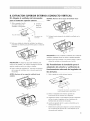
C|. Adaptar el ventilador del microondas s. Coloquela partetrasera0elauni_ad0eventiladorenla
para el extractor exterior posterior
1. Quite y guarde el tornillo que sujeta la plata del ventilador
al microondas.
Tornillo del motor del ventilador
2. Levante la placa del ventilador.
Motor del ventilador
Parte posterior del
microondas
abertura.
DESPUES:Aberturas de Jasaspas deJventilador hacia
atr6s
Extremo A
Extremo B
TornlIlo del motor del ventilador
3. Retire con cuidado la unidad de venfilador. Los cables se
extender6n Io suficiente para permifirle ajustar la unidad de
venfilador.
ANTES: Aberturas de Jas aspas deJ ventilador hacia
adeJante
_._ _ ExtremoB
ExtremoA
PRECAUCION: No toque las aspas del ventilador para
evitar que sequiebren y se rompan. Sostenga la carcasa
exterior cuando se retire y se vuelva a instatar.
4. Rote la unidad de venfilador en senfido contrario alas
agujas del reloi 180 °
Antes de la rotaci6n Despu_s de la rotaci6n
\
Parte posterior del mlcroondas
Parte posterior del microondas
PRECAUCI6N: No tire ni extienda el cabteado de la unidad
de ventitador. Aseggrese de que los cables no queden
apretados.
NOTA: La$ aberturas del extractor de la unidad de
ventilador deben coincidir con las aberturas deJ extractor
en Ja parte trasera deJ homo de microondas.
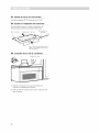
6. Sujete la unidad de ventilador al microondas con el tornillo.
Plata del ventiIador
Pdalt"i r°o to rld°rs
Tornillo de la placa de montaje
7. Sujete el adaptador del extractor a la parte posterior del
homo eoloc6ndolo en las gufas en la parte central superior
de la parte posterior del homo.
Adaptador
Gu_a Tornillo del motor del ventilador
(despu_s de sujetar el adaptador del extractor)
Empgjelo con firmeza hasta que quede en tas pesta_as
de retenci6n inferiores. Aseggrese de que la bisagra del
regulador de tiro de humo est_ instalada para que quede
en la parte superior y que el regulador de tiro se batancee
libremente.
C2. Jnstale eJ homo de microondas
consulte las p6ginas 29_30 (continOe con AI_A3)
33

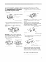
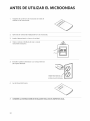
A TS UTILIZAR ELMICROONDAS
1. AsegOrese de que et horno de microondas se instat6 de
acuerdo con las instrucciones.
2. Quite todo el material de embataje del horno de microondas.
3. Instate el plato giratorio y el aro en la cavidad.
4. Vuelva a colocar el fusible de la casa o conecte
nuevamente el disyuntor.
5. Enchufe el cable de alimentaci6n a un tomacorriente de
20 amperes dedicado.
AsegOrese de que existe una
conexi6n a tierra adecuada antes
de utillzar el homo de mlcroondas
6. Lea el Manual dei Usuario.
7. CONSERVE LAS INSTRUCCIONES DE INSTALACI6N PARA USO DEL INSPECTOR LOCAL.
34

NOTA

-
 1
1
-
 2
2
-
 3
3
-
 4
4
-
 5
5
-
 6
6
-
 7
7
-
 8
8
-
 9
9
-
 10
10
-
 11
11
-
 12
12
-
 13
13
-
 14
14
-
 15
15
-
 16
16
-
 17
17
-
 18
18
-
 19
19
-
 20
20
-
 21
21
-
 22
22
-
 23
23
-
 24
24
-
 25
25
-
 26
26
-
 27
27
-
 28
28
-
 29
29
-
 30
30
-
 31
31
-
 32
32
-
 33
33
-
 34
34
-
 35
35
-
 36
36


