
Microwave Oven
Installation manual
ME11A7510** / ME11A7710** / ME11CB7510**

2 English
Before you begin
Before you beginContents
Before you begin 2
General information 3
Important safety instructions 3
Electrical requirements 3
Hood exhaust 4
Damage - Shipment/Installation 6
Parts included 6
Tools you will need 7
Mounting space 7
Step-by-step installation guide 9
Step 1. Placement of the mounting plate 9
Step 2. Ventilation types (choose a, b or c) 12
Step 3. Installation 15
Step 4. Before you use your microwave 19
Before you begin
ABOUT THIS MANUAL
READ THESE INSTRUCTIONS COMPLETELY AND CAREFULLY.
Important
• Save these instructions for local inspector’s use.
• Observe all governing codes and ordinances.
Important note to the installer
Be sure to leave these instructions with the Consumer.
Important note to the consumer
Keep these instructions with your user manual for future reference.
Skill level
Installation of this appliance requires basic mechanical and electrical skills.
Proper installation is the responsibility of the installer
Product failure due to improper installation is not covered under
the Warranty

English 3
General information
General information
IMPORTANT SAFETY INSTRUCTIONS
This product requires a three-prong grounded outlet. The installer must perform a
ground continuity check on the power outlet box before beginning the installation
to ensure that the outlet box is properly grounded. If not properly grounded, or
if the outlet box does not meet electrical requirements noted (under ELECTRICAL
REQUIREMENTS), a qualied electrician should be employed to correct any
deciencies.
CAUTION
For personal safety, remove the house fuse or open the
circuit breaker before beginning the installation to avoid
severe or fatal shock injury.
CAUTION
• For personal safety, the mounting surface must be capable of supporting the
cabinet load in addition to the added weight of this 69 pound product, plus
additional oven loads of up to 50 pounds or a total weight of 119 pounds.
• For personal safety, do not install this product in cabinetry congured as an
island or a peninsula. The microwave oven must be mounted to BOTH a top
cabinet AND a wall.
NOTE
For easier installation and personal safety, we recommend that two people install
this product.
IMPORTANT – PLEASE READ CAREFULLY. FOR PERSONAL SAFETY,
THIS APPLIANCE MUST BE PROPERLY GROUNDED TO AVOID SEVERE
OR FATAL SHOCK.
Insure proper
ground exists
before use.
The power cord of this appliance is equipped with
a three-prong (grounding) plug which mates with a
standard three-prong (grounding) wall receptacle to
minimize the possibility of electric shock hazard from
this appliance.
You should have the wall receptacle and circuit checked by a qualied electrician
to make sure the receptacle is properly grounded.
If you have a standard two-prong wall receptacle, it is very important to have
it replaced with a properly grounded three-prong wall receptacle, installed by a
qualied electrician.
DO NOT, UNDER ANY CIRCUMSTANCES, CUT, DEFORM OR REMOVE ANY OF THE
PRONGS FROM THE POWER CORD. DO NOT USE WITH AN EXTENSION CORD.
ELECTRICAL REQUIREMENTS
Product rating is 120 volts AC, 60 Hertz. This product must be connected to a
supply circuit of the proper voltage and frequency. Wire size must conform to the
requirements of the National Electrical Code or the prevailing local code for this
kilowatt rating. The power supply cord and plug should be brought to a separate
branch circuit single grounded outlet of at least 15 A and max of 20 A. 20 A is
recommended for multifamily buildings. The outlet box should be located in the
cabinet above the microwave oven. The outlet box and supply circuit should be
installed by a qualied electrician and conform to the National Electrical Code or
the prevailing local code.

4 English
General information
General information
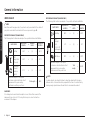
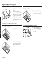
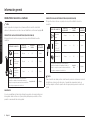
OUTSIDE BACK EXHAUST (EXAMPLE ONLY)
The following chart contains an example of one possible ductwork installation.
DUCT PIECES EQUIVALENT
LENGTH xNUMBER
USED =EQUIVALENT
LENGTH
Wall Cap 40 ft. x(1) =40 ft.
3 Ft.
Straight
Duct
(3 ¼˝ x 10˝
Rectangular)
3 ft. x(1) =3 ft.
90° Elbow 10 ft. x(2) =20 ft.
Equivalent lengths of duct pieces
are based on actual tests and reect
requirements for good venting
performance with any vent hood.
Total
Length =63 ft.
NOTE
For back exhaust, care should be taken to align the exhaust with the space
between studs, or the wall should be prepared at the time it is constructed by
leaving enough space between the wall studs to accommodate exhaust.
HOOD EXHAUST
NOTE
Read these next two pages only if you plan to vent your exhaust to the outside. If
you plan to recirculate the air back into the room, proceed to page 12.
OUTSIDE TOP EXHAUST (EXAMPLE ONLY)
The following chart contains an example of one possible ductwork installation.
DUCT PIECES EQUIVALENT
LENGTH xNUMBER
USED =EQUIVALENT
LENGTH
Roof Cap 24 ft. x(1) =24 ft.
12 Ft.
Straight Duct
(6˝ Round)
12 ft. x(1) =12 ft.
Rectangular-
to-Round
Transition
Adaptor*
5 ft. x(1) =5 ft.
Equivalent lengths of duct pieces
are based on actual tests and reect
requirements for good venting
performance with any vent hood.
Total Length =41 ft.
IMPORTANT:
If a rectangular-to-round transition adaptor is used, the bottom corners of the
damper will have to be cut to t, using the tin snips, in order to allow free
movement of the damper.

English 5
General information
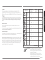
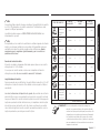
DUCT PIECES EQUIVALENT
LENGTH xNUMBER
USED =EQUIVALENT
LENGTH
Rectangular-
to-Round
Transition
Adaptor*
5 ft. x( ) =ft.
Wall Cap 40 ft. x( ) =ft.
90 ° Elbow 10 ft. x( ) =ft.
45 ° Elbow 5 ft. x( ) =ft.
90 ° Elbow 25 ft. x( ) =ft.
45 ° Elbow 5 ft. x( ) =ft.
Roof Cap 24 ft. x( ) =ft.
Straight Duct
6˝ Round or
3 ¼˝ x 10˝
Rectangular
1 ft. x( ) =ft.
Total Ductwork =ft.
*IMPORTANT: If a rectangular-to-round transition adaptor is
used, the bottom corners of the damper will
have to be cut to t, using tin snips, to allow free
movement of the damper.
Equivalent lengths of duct pieces are based on
actual tests and reect the requirements for good
venting performance with any vent hood.
NOTE
If you need to install ducts, note that the total duct length of 3 ¼˝ x 10˝
rectangular or 6˝ diameter round duct should not exceed 140 equivalent feet.
Outside ventilation requires a HOOD EXHAUST DUCT. Read the following carefully.
NOTE
It is important that venting be installed using the most direct route and with as
few elbows as possible. This ensures clear venting of exhaust and helps prevent
blockages. Also, make sure dampers swing freely and nothing is blocking the
ducts.
Exhaust connection:
The hood exhaust has been designed to mate with a standard 3 ¼˝ x 10˝
rectangular duct.
If a round duct is required, a rectangular-to-round transition adaptor must be used.
Do not use less than a 6˝ diameter duct.
Maximum duct length:
For satisfactory air movement, the total duct length of 3 ¼˝ x 10˝ rectangular or 6˝
diameter round duct should not exceed 140 equivalent feet.
Elbows, transitions, wall and roof caps, etc. present additional resistance to airow
and are equivalent to a section of straight duct which is longer than their actual
physical size. When calculating the total duct length, add the equivalent lengths of
all transitions and adaptors plus the length of all straight duct sections. The chart
below shows you how to calculate total equivalent ductwork length using the
equivalent length in feet of some typical ducts.

6 English
General information
General information
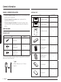
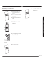
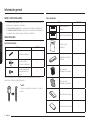
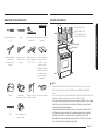
ADDITIONAL PARTS
PART QUANTITY
TOP CABINET TEMPLATE
REAR WALL TEMPLATE
Top Cabinet Template 1
TOP CABINET TEMPLATE
REAR WALL TEMPLATE Rear Wall Template 1
Installation Instructions 1
Template
INSTALLATION
INSTRUCTIONS
Exhaust Adaptor 1
Separately Packed
Grease Filters 2
Separately Packed
Charcoal Filters 2
Cover Air-Right 2
Cover Air-Left 1
DAMAGE SHIPMENT/INSTALLATION
• If the unit is damaged in shipment, return the unit to the store in which it was
bought for repair or replacement.
• If the unit is damaged by the customer, repair or replacement is the
responsibility of the customer.
• If the unit is damaged by the installer (if other than the customer), repair
or replacement must be made by arrangement between the customer and
installer.
PARTS INCLUDED
HARDWARE PACKET
PART QUANTITY
Template
INSTALLATION
INSTRUCTIONS
Wood Screws 1
Template
INSTALLATION
INSTRUCTIONS
Toggle Bolts
(and wing nuts) 2
Self-aligning
Machine Screws
With Supporter
2
You will nd the installation hardware contained in a packet with the unit. Check to
make sure you have all these parts.
NOTE
If Cabinet Thickness is over 1 ˝, Remove
Supporter.

English 7
General information
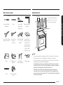
MOUNTING SPACE
10 11/16˝
24 1/5˝
30˝
5˝
Bottom edge of the cabinet
needs to be 24 1
/5˝ or more
from the cooking surface.
Backsplash
12˝ max.
NOTE
• The space between the cabinets must be 30˝ wide and free of obstructions.
• This microwave oven is for installation over ranges up to 36˝ wide.
• If you are going to vent your microwave oven to the outside, see the Hood
Exhaust Section for exhaust duct preparation.
• If installing the microwave oven beneath smooth at cabinets, be careful to
follow the instructions on the top cabinet template for power cord clearance.
• Maximum cabinet depth above and beside the unit is 12˝.
• The dimensions provided are the minimum required for mounting the
microwave oven. Local codes and the practical use of the range will likely
require you to provide more than the 13.5˝ shown between the range and the
bottom of the microwave.
TOOLS YOU WILL NEED
#1 and #2 Phillips
screwdriver
Pencil Ruler or tape
measure and
straight edge
Carpenter square
(optional)
Tin snips (for cutting
damper, if required)
Scissors (to cut
template, if
necessary)
Electric drill with
3/16˝, 1/2˝ and 5/8˝
drill bits
Filler blocks or
scrap wood pieces,
if needed for top
cabinet spacing
(used on recessed
bottom cabinet
installations only)
Gloves Saw (saber, hole or
keyhole)
Stud nder or
Hammer (optional)
Safety goggles
Level Duct and masking
tape
10 11/16˝

8 English
General information
General information
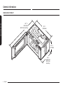
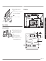
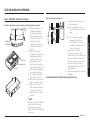
DIMENSION OF PRODUCT
46 11/16˝
(1185.9mm)
With Plate mounting 29 7/8˝
(758.8mm)
10 11/16˝
(272.0mm)
19 3/16˝
(486.7mm)
With Plate
mounting

English 9
Step-by-step installation guide
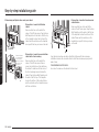
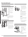
B. Finding the wall studs
Center
Wall Studs
1. Find the studs using one of the
following methods:
A. With a stud nder – a magnetic
device which locates nails.
OR
B. Use a hammer to tap lightly
across the mounting surface until
you hear a solid sound. This will
indicate a stud location.
2. After locating the stud(s), locate the
stud’s center by probing the wall
with a small nail to nd the edges of
the stud. Then, place a mark halfway
between the edges. The center of
any adjacent studs should be 16˝ or
24˝ from this mark.
3. Draw a line down the center of the
studs.
THE MICROWAVE MUST BE CONNECTED TO AT LEAST ONE WALL STUD.
Step-by-step installation guide
Step 1. Placement of the mounting plate
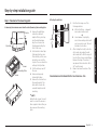
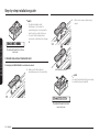
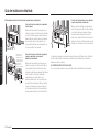
A. Removing the microwave oven from the carton/Removing the mounting plate
Carton
Styrofoam
Mounting Plate
Screws
Screws
1. Remove the installation
instructions, Exhaust
Adaptor, lters, glass tray,
and the small hardware
bag. Do not remove the
Styrofoam protecting the
front of the oven.
2. Fold back all 4 carton aps
fully against carton sides.
Then carefully roll the oven
and carton over onto the
top side. The oven should be
resting in the Styrofoam.
3. Pull the carton up and off
the oven.
4. Remove and properly
discard plastic bags.
5. Remove the 2 screws from
the mounting plate. This
plate will be used as the
rear wall template and for
mounting.
NOTE
Retain the two screws. You will
need to re-insert the screws in
their original locations after you
have removed the mounting
plate.

10 English
Step-by-step installation guide
Step-by-step installation guide
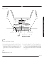
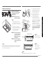
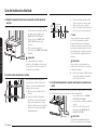
C. Determining wall plate location under your cabinet
C
L
At least 30˝
Plate position – beneath a at bottom
cabinet.
Draw a vertical line on the wall at the
center of the 30˝ wide space. Tape the Rear
Wall Template onto the wall so that the top
of the template touches the bottom of the
cabinet and the centerline on the template
lines up with the line you drew on the wall.
`
i
Plate position – beneath recessed bottom
cabinet with front overhang
Draw a horizontal
line to mark how
far the inside of
the front overhang
descends below
the cabinet.
24 1/5˝
Plate position – beneath a recessed bottom
cabinet with a front overhang.
Draw a vertical line on the wall at the
center of the 30˝ wide space. Draw a
second, horizontal line on the wall below
the cabinet to mark how far the inside of
the front overhang descends below the
cabinet. Tape the Rear Wall Template onto
the wall so that the top of the template
touches the bottom of the horizontal line
and the centerline on the template lines up
with the vertical line.
C
L
24 1/5˝
Plate position – beneath a framed recessed
cabinet bottom.
Draw a vertical line on the wall at the
center of the 30˝ wide space. Tape the Rear
Wall Template onto the wall so that the top
of the template touches the bottom of the
cabinet frame and the centerline on the
template lines up with the line you drew
on the wall.
Your cabinets may have decorative trim that interferes with the microwave
installation. Remove the decorative trim to install the microwave properly and to
make it level.
THE MICROWAVE MUST BE LEVEL.
Use a level to make sure the cabinet bottom is level.

English 11
Step-by-step installation guide
1. Draw a horizontal line on the wall at the bottom of the “Rear Wall Template”.
2. Drill 5/8˝ holes for toggle bolts in 2 locations (Hole A, Hole B) as shown in the
illustration above. If the location of a hole lines up with a stud, drill a 3/16˝ hole
for a wood screw. You cannot use a toggle bolt to attach the wall plate to a
stud.
NOTE
DO NOT MOUNT THE PLATE AT THIS TIME.
D. Aligning the wall plate
NOTE: IT IS VERY IMPORTANT TO
READ AND FOLLOW THE DIRECTIONS
IN THE INSTALLATION INSTRUCTIONS
BEFORE PROCEEDING WITH THIS
REAR WALL TEMPLATE.
This Rear Wall Template serves to position the bottom
mounting plate and to locate the horizontal exhaust outlet
1. Use a level to check that the template is positioned accurately.
2. Locate and mark at least one stud on the left or right side of the centerline.
NOTE:
It is important to use at least one wood screw mounted rmly in a stud to support
the weight of the microwave. Mark two additional, evenly spaced locations for
the supplied toggle bolts.
3. Drill holes in the marked locations. Where there is a stud, drill a 3/16” hole for wood screws,
for holes that do not line up with a stud, drill 5/8” holes for toggle bolts
NOTE:
DO NOT INSTALL THE MOUNTING PLATE AT THIS TIME.
4. Remove the template from the rear wall.
5. Review the Installation Instruction book for your installation situation.
Français au verso.
3/8
"
TO EDGE
F. CUT OUT FOR HORIZONTAL
OUTSIDE EXHAUSE
CUT HOLE THROUGH REAR WALL FOR EXHAUST ADAPTOR
REAR WALL TEMPLATE
CAUTION - IF EXHAUST ADAPTOR IS POSITIONED OUTSIDE
RECOMMENDED DIMENSION, GREASE-LADEN AIR WILL
DISCHARGE INTO HOUSE STRUCTURE.
Locate and mark holes to align with holes in the mounting plate.
IMPORTANT:
LOCATE AT LEAST ONE STUD ON EITHER SIDE OF THE CENTERLINE.
MARK THE LOCATION FOR 2 ADDITIONAL, EVENLY SPACED TOGGLE
BOLTS IN THE MOUNTING PLATE AREA.
IT IS RECOMMENDED TO INSTALL BOLTS IN A, B, AND C HOLES. THE LOCATION
MAY BE SUBJECT TO CHANGE ACCORDING TO CIRCUMSTANCES BUT IT IS
RECOMMENDABLE TO INSTALL THEM NEAR THE THREE HOLES MENTIONED.
Trim the rear wall template along the dotted line.
Trim the rear wall template along the dotted line.
Locate and mark holes to align with holes in the mounting plate.
IMPORTANT:
LOCATE AT LEAST ONE STUD ON EITHER SIDE OF THE CENTERLINE.
MARK THE LOCATION FOR 2 ADDITIONAL, EVENLY SPACED TOGGLE
BOLTS IN THE MOUNTING PLATE AREA.
IT IS RECOMMENDED TO INSTALL BOLTS IN A, B, AND C HOLES. THE LOCATION
MAY BE SUBJECT TO CHANGE ACCORDING TO CIRCUMSTANCES BUT IT IS
RECOMMENDABLE TO INSTALL THEM NEAR THE THREE HOLES MENTIONED.
Printed in Malaysia
DE68-04707A-00
30" MINIMUM WIDTH REQUIRED
Draw a horizontal line on the wall along the
bottom of the “Rear Wall Template”.
Draw a vertical line on the
wall to mark the center of
the cabinet above.
Horizontal Line
Area E
Centerline
notches
Hole A Hole B
Hole C
Horizontal Line
CAUTION
Wear gloves to avoid cutting ngers on sharp edges.
3. Holes A and B are inside area E. If none of these holes line up with a stud,
nd a stud in area E that lines up with a hole circle in Area E, and then drill
a 3/16˝ hole into it for a wood screw. You must have at least one wood screw
mounted rmly into a stud to support the weight of the microwave. Set the
mounting plate aside.

12 English
Step-by-step installation guide
Step-by-step installation guide
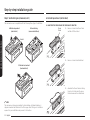
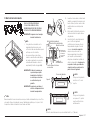
Step 2. Ventilation types (choose A, B or C)
This microwave oven is compatible with the following three types of ventilation:
A. Outside top exhaust
(vertical duct)
B. Recirculating
(non-vented ductless)
Bracket
C. Outside back exhaust
(horizontal duct)
NOTE
This microwave is shipped assembled for Recirculating. An Exhaust Adaptor is
shipped assembled and attached to the ller-upper. Select the type of ventilation
required for your installation and proceed to that section.
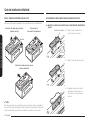
A. Outside top exhaust (vertical duct)
A1. ADAPTING THE COVER PANEL FOR THE EXHAUST ADAPTOR
Cover
Panel
Back
Panel
1. Remove 1 screw from Cover Panel
and take off Cover Panel.
2. Remove 1 screw from Back Panel.
3. Assemble the Cover Panel as sliding
from top to bottom and the screw
that was removed from Back Panel.

English 13
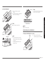
Step-by-step installation guide
Bracket
The marked Brackets should not
have Vent holes.
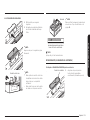
NOTE
You must check bracket picture according
to ventilation type at page 12.
NOTE
Apply A1 and A2 equally.
B. Recirculating (non-vented ductless)
B1. Adapting the COVER PANEL for recirculation
Cover
Panel
Back
Panel
1. Make sure the Cover Panel is
assembled properly. (Top assembly)
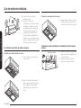
A2. INSTALLATION DAMPER
Damper
1. Remove the tape securing the
Damper.
2. Assemble the Damper as sliding from
back to front until stopped.
NOTE
Make sure Dampers swing freely.
House Duct
House Duct NOTE
• You must attach the House Duct to
the Exhaust Adaptor after installation
is complete.
• You must seal Exhaust Duct joints
using Duct Tape.

14 English
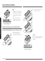
Step-by-step installation guide
Step-by-step installation guide
Plate
8EA
After removing Plates
2. Cut 8 area to remove plates using
nipper.
The marked Brackets should not
have Vent holes.
NOTE
You must check bracket picture according
to ventilation type at page 12.
The marked Brackets should have
Vent holes.
NOTE
• The Exhaust Adaptor with
the Damper is not needed for
recirculating type. You may want to
save them for possible future use.
• You must check bracket picture
according to ventilation type at page
12.
C. Outside back exhaust (horizontal duct)
C1. Adapting the COVER PANEL for outside back exhaust
1. Make sure the Cover Panel is
assembled properly. (Top assembly)

English 15
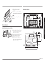
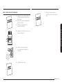
Step-by-step installation guide
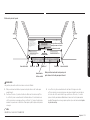
Dim. Comparison
13
9
14
12
12
5
34
6
12
6
14
13
3 32
(332.4mm)
9 14
(235mm)
13
3
32
(332.4mm)
9 14
(235mm)
1
12
115 32
(37.3mm)
34
4
34
4
6
31 64
(164.5mm)
CUT OUT SLOT
FOR SMOOTH
FLAT BOTTOM
CABINETS ONLY
POWER
CORD
CUT OUT SLOT
FOR SMOOTH
FLAT BOTTOM
CABINETS ONLY
Screw exposure length
(Cabinet bottom to End of bolt)
without the Supporter.
2832 1
2632
~
(46mm) (22mm)
Screw exposure length
(Cabinet bottom to End of bolt)
when using the Supporter.
2832 1
3032
~
(49mm) (22mm)
NOTE
After assembling the screws in the D and E holes,
check the dimensions.
11
716
(290.75mm)
6
31 64
(164.5mm)
DE68-04708A-00
3 1/2˝
(88.7mm)
1 27/32˝
(47mm)
9 1/4˝
(235mm)
1 15/32˝
(37.3mm)
26 3/16˝
(664.8mm) 1 27/32˝
(47mm)
3. Remove the tape securing the
Damper.
4. Assemble the Damper as sliding from
top to bottom until stopped.
NOTE
Make sure Dampers swing freely.
Step 3. Installation
INSTALLATION OVERVIEW
F. CUT OUT FOR HORIZONTAL
OUTSIDE EXHAUSE
REAR WALL TEMPLATE
A. Prepare the Rear Wall (for outside
back exhaust/horizontal duct only).
B. Attach the Mounting Plate to the
Wall.
C. Prepare the Cabinet above.
D. Mount the Microwave Oven.
E. Connect the Ductwork (for outside
top exhaust/vertical duct only).

16 English
Step-by-step installation guide
Step-by-step installation guide
Bolt End
Mounting
Plate Toggle
Bolt
Wall
Toggle Wings
3. Place the mounting plate against
the wall, pinch the wings of each
toggle together, and then insert the
toggle wings of each toggle into and
through the holes in the wall.
NOTE
Before tightening the toggle bolts and
wood screw, make sure the bottom
of the Mounting plate runs along the
bottom Horizontal line of the “Rear wall
Template” and the Mounting plate is
properly centered under the cabinet.
CAUTION
Be careful to avoid pinching your ngers
between the back of the mounting plate
and the wall.
4. Tighten all bolts. Pull the plate away
from the wall to help tighten the
bolts. Tighten the screw.
C. Use the top cabinet template to prepare the cabinet above
You need to drill holes for the top support screws and a hole large enough for the
power cord to t through.
• Read the instructions on the TOP
CABINET TEMPLATE.
• Tape it underneath the top cabinet.
• Drill the holes, following the
instructions on the TOP CABINET
TEMPLATE.
CAUTION
Wear safety goggles when drilling holes
in the cabinet bottom.
A. Prepare the rear wall for outside back exhaust
You need to cut an opening in the rear wall for outside exhaust.
C
L
• Read the instructions for outside
back exhaust on the REAR WALL
TEMPLATE.
• Tape the REAR WALL TEMPLATE to
the rear wall.
• Cut the opening, following the
instructions on the REAR WALL
TEMPLATE.
CAUTION
Do not cut an opening in the rear wall
if you are installing the microwave with
vertical duct or non-vented ductless
ventilation.
B. Attach the mounting plate to the wall
Attach the plate to the wall using toggle
bolts. At least one wood screw must be
used to attach the plate to a wall stud.
1. Remove the toggle wings from the
bolts.
2. Insert the bolts into the mounting
plate through the holes designated
to go into drywall, and then reattach
the toggle wings so that ¾˝ of the
bolt protrudes beyond the wing.

English 17
Step-by-step installation guide
Equivalent
to Depth
of Cabinet
Recess
Cabinet Bottom Shelf
Microwave Oven Top
Cabinet Front
Filler Block
Self-Aligning
Screw
1. Lift the microwave, tilt it forward,
and hook the slots at the back
bottom edge onto the four lower
tabs of the mounting plate.
2. Rotate the front of the oven up
against the cabinet bottom.
3. Insert a self-aligning screw
through the top center cabinet
hole. Temporarily secure the oven
by turning the screw at least two
full turns after the threads have
engaged. (It will be completely
tightened later.) Be sure to keep
the power cord tight. Be careful not
to pinch the cord, especially when
mounting ush to the bottom of
cabinet.
Thickness of cabinet
¹/~
15
/”
1
/16
~15/16 ˝
Supporter
NOTE
If Cabinet Thickness is
Under 1 ˝, Use Supporter.
1
~
2”
1~2˝
NOTE
If Cabinet Thickness
is over 1 ˝, Remove
Supporter from the Self-
Aligning Screw.
NOTE
The self-aligning screw can be installed up to 1 15/16 ˝ (49mm).
D. Mount the microwave oven
FOR EASIER INSTALLATION AND
PERSONAL SAFETY, WE RECOMMEND
THAT TWO PEOPLE INSTALL THIS
MICROWAVE OVEN.
IMPORTANT: Do not grip or use the
handle during installation.
NOTE
• If your cabinet is metal, use the
nylon grommet in the power cord
hole to prevent the cord from being
cut.
• Filler blocks are required when
mounting this unit under any cabinet
with a recessed bottom or front
overhang. (See page 10.)
IMPORTANT: The case damage that will
occur from over tightening
screws if you do not use
ller blocks is not covered
under warranty.
IMPORTANT: Be careful not to damage
the lower Lamp Glass during
handling.
NOTE
When mounting the microwave oven, thread the power cord through hole in the
bottom of the top cabinet. Keep it tight throughout Steps 1–3. Do not pinch the
cord or lift the oven by pulling cord.

18 English
Step-by-step installation guide
Step-by-step installation guideStep-by-step installation guide
E2. Grease Filter assembly method
1. Push the Grease Filter backward and
insert the Grease Filter until atness
with bottom surface of products.
F. Connect the ductwork for outside top exhaust
House Duct
House Duct 1. Extend the House Duct down to
connect to the Exhaust Adaptor.
2. Seal the exhaust duct joints using
duct tape.
4. Attach the microwave oven to the
top cabinet.
5. Insert the 2 self-aligning screws
through the cabinet bottom shelf and
ller block into the outer top cabinet
of the unit. Continue to support the
unit until both screws are inserted
and engaged at least two full turns,
then fully tighten all screws until the
unit is secure.
E. Installing the charcoal lters and Grease Filters
E1. Charcoal Filter assembly method
1. Insert the Charcoal Filter from the
back.
2. Raise the front of the Charcoal Filter
until it is at with the bottom, and
then pull it forward to lock it in
place.

English 19
Step-by-step installation guide
7. Keep installation instructions for the
local inspector’s use.
Step 4. Before you use your microwave
1. Make sure the microwave oven
has been installed according to
instructions.
2. Remove all packing material from the
microwave oven.
3. Install the turntable and ring in the
cavity.
4. Replace the house fuse or turn the
breaker back on.
Insure proper
ground exists
before use.
5. Plug the power cord into a dedicated
15 amp electrical outlet.
6. Read the Owner’s Manual.

Please be advised that the Samsung warranty does NOT cover service calls to explain product operation, correct improper installation, or perform normal cleaning or
maintenance.
QUESTIONS OR COMMENTS?
COUNTRY CALL OR VISIT US ONLINE AT
U.S.A
Consumer Electronics 1-800-SAMSUNG (726-7864) www.samsung.com/us/support
CANADA 1-800-SAMSUNG (726-7864) www.samsung.com/ca/support (English)
www.samsung.com/ca_fr/support (French)
DE68-04709A-02
Scan the QR code* or visit
www.samsung.com/spsn
to view our helpful
How-to Videos and Live Shows
* Requires reader to be installed on your
smartphone

Horno de microondas
Manual de instalación
ME11A7510** / ME11A7710** / ME11CB7510**

2 Español
Antes de comenzar
Antes de comenzar
Contenido
Antes de comenzar 2
Información general 3
Instrucciones de seguridad importantes 3
Requisitos eléctricos 3
Conducto de salida de la campana 4
Daños: envío/instalación 6
Piezas incluidas 6
Herramientas que necesitará 7
Espacio para montaje 7
Guía de instalación detallada 9
Paso 1. Colocación de la placa de montaje 9
Paso 2. Tipos de ventilación (elija A, B o C) 12
Paso 3. Instalación 15
Paso 4. Antes de usar el microondas 19
Antes de comenzar
Acerca de este manual
LEA ESTAS INSTRUCCIONES EN SU TOTALIDAD Y CUIDADOSAMENTE.
Importante
• Guarde estas instrucciones para que puedan ser consultadas por el inspector
local.
• Cumpla todos los códigos y ordenanzas exigidos por las autoridades
pertinentes.
Nota importante para el instalador
Asegúrese de dejar estas instrucciones al usuario.
Nota importante para el usuario
Conserve estas instrucciones con el manual del usuario para su referencia futura.
Nivel de habilidades
La instalación de este electrodoméstico requiere habilidades eléctricas y mecánicas
básicas.
El instalador es responsable de la instalación adecuada
La falla del producto debido a la instalación incorrecta no está
cubierta por la garantía

Español 3
Información general
Información general
INSTRUCCIONES DE SEGURIDAD IMPORTANTES
Este producto requiere un tomacorriente de conexión a tierra de tres clavijas. El
instalador debe realizar un control de la continuidad de la conexión a tierra en la
caja del tomacorriente antes de comenzar la instalación con el n de garantizar
que esta caja esté debidamente conectada a tierra. Si no lo está o si la caja del
tomacorriente no cumple con los requisitos eléctricos indicados (en REQUISITOS
ELÉCTRICOS), se debe contratar a un electricista calicado para corregir cualquier
deciencia.
PRECAUCIÓN
Para la seguridad personal, quite el fusible de la casa o
abra el disyuntor antes de comenzar la instalación para
evitar una lesión por choque mortal o grave.
PRECAUCIÓN
• Para su seguridad, la supercie de montaje debe ser capaz de soportar la carga
del gabinete, además del peso agregado de este producto de 69 libras (31 kg),
más cargas adicionales del horno de hasta 50 libras (23 kg) o un peso total de
119 libras (49 kg).
• Para su seguridad, no instale este producto en los gabinetes congurados como
isla o península. El horno microondas se debe montar TANTO en un gabinete
superior COMO en una pared.
NOTA
Para su seguridad y una instalación más fácil, recomendamos que dos personas
instalen este producto.
IMPORTANTE - LEA DETENIDAMENTE. PARA SU SEGURIDAD, ESTE
ELECTRODOMÉSTICO SE DEBE CONECTAR A TIERRA DE MANERA
CORRECTA PARA EVITAR UNA DESCARGA MORTAL O GRAVE.
Asegúrese de
que exista una
conexión a tierra
adecuada antes
de usar.
El cable de alimentación de este electrodoméstico cuenta
con un enchufe (de conexión a tierra) de tres clavijas, que
se acopla con un tomacorriente de pared (de conexión
a tierra) de tres clavijas para minimizar la posibilidad
de que haya un peligro de descarga eléctrica de este
electrodoméstico.
Un electricista calicado debe revisar el tomacorriente de pared y el circuito para
asegurarse de que el tomacorriente esté conectado a tierra de manera correcta.
Si tiene un tomacorriente de pared de dos clavijas estándar, es muy importante que
lo reemplace por uno de tres clavijas debidamente conectado a tierra e instalado por
un electricista calicado.
BAJO NINGUNA CIRCUNSTANCIA CORTE, DEFORME NI QUITE NINGUNA DE LAS
CLAVIJAS DEL CABLE DE ALIMENTACIÓN. NO LO UTILICE CON UN ALARGUE.
REQUISITOS ELÉCTRICOS
La clasicación eléctrica del producto es de 120 V de CA, 60 Hz. Este producto
se debe conectar a un circuito de suministro de frecuencia y voltaje correctos. El
tamaño del cable debe cumplir con los requisitos del Código Eléctrico Nacional o
el código local vigente para estos valores de kilovatios. El enchufe y el cable de
alimentación se deben colocar en un tomacorriente conectado a tierra simple con
circuito derivado independiente de 15 A como mínimo y 20 A como máximo. Uso de
20 A se recomienda para edicios multifamiliares. La caja del tomacorriente debe
estar en el gabinete, por encima del horno microondas. Un electricista calicado
debe instalar la caja del tomacorriente y el circuito de alimentación, y deben cumplir
con el Código Eléctrico Nacional o el código local vigente.

4 Español
Información general
Información general
CONDUCTO DE SALIDA POSTERIOR EXTERNO (SOLO DE EJEMPLO)
El siguiente cuadro contiene un ejemplo de una posible instalación de red de
conductos.
PIEZAS DE CONDUCTOS LONGITUD
EQUIVALENTE xCANTIDAD
USADA =LONGITUD
EQUIVALENTE
Tapa de la
pared 40 pies x (1) = 40 pies
3 pies
Conducto
recto
(3 ¼" x 10"
rectangular)
3 pies x (1) = 3 pies
Codo de 90º 10 pies x (2) = 20 pies
Las longitudes equivalentes de las piezas de
conductos se basan en las pruebas actuales y
reejan los requisitos para una buena ventilación
con cualquier campana de ventilación.
Longitud
total = 63 pies
NOTA
Para el conducto de salida posterior, debe tener la precaución de alinear el conducto
de salida con el espacio entre las vigas, o la pared debe prepararse cuando se
construye dejando suciente espacio entre las vigas para que pase el conducto de
salida.
CONDUCTO DE SALIDA DE LA CAMPANA
NOTA
Lea las siguientes dos páginas solo si planea ventilar el conducto de salida al
exterior. Si planea volver a circular el aire en la habitación, continúe en la página 12.
CONDUCTO DE SALIDA SUPERIOR EXTERNO (SOLO DE EJEMPLO)
El siguiente cuadro contiene un ejemplo de una posible instalación de red de
conductos.
PIEZAS DE CONDUCTOS LONGITUD
EQUIVALENTE xCANTIDAD
USADA =LONGITUD
EQUIVALENTE
Tapa de techo 24 pies x (1) = 24 pies
12 pies
Conducto recto
(6" redondo)
12 pies x (1) = 12 pies
Adaptador
de transición
rectangular a
redondo*
5 pies x (1) = 5 pies
Las longitudes equivalentes de las piezas de
conductos se basan en las pruebas actuales y
reejan los requisitos para una buena ventilación
con cualquier campana de ventilación.
Longitud total = 41 pies
IMPORTANTE:
Si se usa un adaptador de transición rectangular a redondo, las esquinas inferiores
del regulador deben cortarse con tijeras para hojalata para que encastre, a n de
permitir un movimiento libre del regulador.

Español 5
Información general
PIEZAS DE CONDUCTOS LONGITUD
EQUIVALENTE xCANTIDAD
USADA =LONGITUD
EQUIVALENTE
Adaptador
de transición
rectangular a
redondo*
5 pies x ( ) = pies
Tapa de la
pared 40 pies x ( ) = pies
Codo de 90º 10 pies x ( ) = pies
Codo de 45º 5 pies x ( ) = pies
Codo de 90º 25 pies x ( ) = pies
Codo de 45º 5 pies x ( ) = pies
Tapa de techo 24 pies x ( ) = pies
Conducto recto
Redondo de 6"
o rectangular
de 3 ¼" x 10"
1 pie x ( ) = pies
Red de conductos total = pies
*IMPORTANTE: Si se usa un adaptador de transición rectangular a
redondo, las esquinas inferiores del regulador deberán
cortarse con tijeras para hojalata para que encastre, a n
de permitir que el regulador pueda moverse libremente.
Las longitudes equivalentes de las piezas del conducto
se basan en las pruebas actuales y reejan los requisitos
para un rendimiento de buena ventilación con cualquier
campana de ventilación.
NOTA
Si necesita instalar conductos, tenga en cuenta que la longitud total del conducto
de 3 ¼" x 10" rectangular o el conducto redondo de 6" de diámetro no debe
superar los 140pies equivalentes.
La ventilación externa requiere un CONDUCTO DE SALIDA DE CAMPANA. Lea
detenidamente lo siguiente.
NOTA
Es importante que los conductos de ventilación se instalen siguiendo la ruta más
directa y con la menor cantidad de codos posibles. Esto garantiza una buena
ventilación del conducto de salida y ayuda a evitar obstrucciones. Además,
asegúrese de que los reguladores giren libremente y que los conductos no
presenten obstrucciones.
Conexión del conducto de salida:
El conducto de salida de la campana está diseñado para acoplarse con un conducto
rectangular de 3 ¼" x 10" estándar.
Si se requiere un conducto redondo, se debe usar un adaptador de transición
rectangular a redondo. No use un conducto de menos de 6" de diámetro.
Longitud máxima del conducto:
Para un movimiento de aire satisfactorio, la longitud total del conducto de 3 ¼" x 10"
rectangular o el conducto redondo de 6" de diámetro no debe superar los 140 pies
equivalentes.
Los codos, las transiciones, las tapas de techo y pared, etc. presentan una resistencia
adicional al ujo de aire y son equivalentes a una sección de un conducto recto más
largo que su tamaño físico real. Al calcular la longitud del conducto total, agregue las
longitudes equivalentes de todas las transiciones y los adaptadores, más la longitud
de todas las secciones del conducto recto. En el cuadro a continuación, se muestra
cómo calcular la longitud de la red de conductos equivalente mediante el uso de la
longitud equivalente en pies de algunos conductos típicos.

6 Español
Información general
Información general
PIEZAS ADICIONALES
PIEZA CANTIDAD
TOP CABINET TEMPLATE
REAR WALL TEMPLATE
Molde del gabinete
superior 1
TOP CABINET TEMPLATE
REAR WALL TEMPLATE
Molde para pared trasera 1
Instrucciones de
instalación 1
Template
INSTALLATION
INSTRUCTIONS
Adaptador del conducto
de salida 1
Filtros de grasa
embalados por separado 2
Filtros de carbón
embalados por separado 2
Cubierta de aire derecha 2
Cubierta de aire izquierda 1
DAÑOS - ENVÍO/INSTALACIÓN
• Si la unidad se daña durante el envío, devuelva la unidad a la tienda donde la
compró para su reparación o reemplazo.
• Si el cliente daña la unidad, este es responsable de repararla o reemplazarla.
• Si el instalador daña la unidad (en caso de que no sea el cliente), la reparación o
el reemplazo deben acordarse entre el cliente y el instalador.
PIEZAS INCLUIDAS
PAQUETE DE ACCESORIOS
PIEZA CANTIDAD
Template
INSTALLATION
INSTRUCTIONS
Tornillos para madera 1
Template
INSTALLATION
INSTRUCTIONS
Tornillos de ador
(y tuercas de mariposa) 2
Tornillos para máquina
de autoalineación con
soporte
2
Encontrará los accesorios de instalación incluidos en un paquete con la unidad.
Asegúrese de contar con todas estas piezas.
NOTA
Si el grosor del gabinete es superior a 1", quite el
soporte.

Español 7
Información general
ESPACIO PARA MONTAJE
24 1/5"
30
5
El borde inferior del
gabinete debe ser de
24
1
/
5
" o más desde la
supercie de la cocina.
Protector contra
salpicaduras
12" máx.
NOTA
• El espacio entre los gabinetes debe ser de 30" de ancho y sin obstrucciones.
• Este horno microondas es para la instalación sobre estufas de hasta 36" de
ancho.
• Si va a ventilar el horno microondas al exterior, consulte la sección Conducto de
salida de la campana para la preparación del conducto de salida.
• Si instala el horno microondas por encima de los gabinetes planos y lisos, tenga
cuidado de seguir las instrucciones en el molde del gabinete superior para la
separación del cable de alimentación.
• La profundidad máxima del gabinete sobre y al costado de la unidad es de 12".
• Las dimensiones proporcionadas son las mínimas requeridas para el montaje
del horno microondas. Los códigos locales y el uso práctico de la estufa
probablemente requerirán que proporcione más de los 13,5" que se muestran
entre la estufa y la parte superior del microondas.
HERRAMIENTAS QUE NECESITARÁ
Destornillador Phillips
n.º 1 y 2
Lápiz Regla o cinta de medir
y borde recto
Escuadra de carpintero
(opcional)
Tijeras para hojalata
(para cortar el
regulador si fuera
necesario)
Tijeras (para cortar
el molde si fuera
necesario)
Taladro eléctrico con
mechas de perforación
de
3
/
16
",
1
/
2
" y
5
/
8
"
Piezas de madera de
desecho o bloques
de relleno, si fuera
necesario, para el
espaciado del gabinete
superior (solo para uso
en instalaciones de
gabinetes superiores
empotrados)
Guantes Sierra (sable,
perforadora o de calar)
Detector de vigas o
martillo (opcional)
Anteojos de seguridad
Nivel Cinta de enmascarar y
para conductos

8 Español
Información general
Información general
DIMENSIÓN DEL PRODUCTO
46
11
/
16
"
(1185.9 mm)
con montaje de la placa 29
7
/
8
"
(758.8 mm)
10
11
/
16
"
(272.0 mm)
19
3
/
16
"
(486.7 mm)
con montaje
de la placa

Español 9
Guía de instalación detallada
B. Encontrar las vigas de la pared
Centro
Vigas
1. Encuentre las vigas mediante uno de
los siguientes métodos:
A. Con un buscador de vigas: un
dispositivo magnético que detecta
clavos.
O
B. Use un martillo para golpear
suavemente la supercie de
montaje hasta oír el sonido de
un elemento sólido. Esto indica la
ubicación de una viga.
2. Una vez que encuentre las
vigas, ubique el centro de estas
introduciendo un clavo pequeño en la
pared para detectar los bordes de la
viga. Luego, coloque una marca entre
los bordes. El centro de cualquier
viga adyacente debe ser de 16" o 24"
desde esta marca.
3. Trace una línea del centro de las vigas
hacia abajo.
EL MICROONDAS DEBE ESTAR CONECTADO A AL MENOS UNA VIGA.
Guía de instalación detallada
Paso 1. Colocación de la placa de montaje
A. Quitar el horno microondas de la caja de cartón/quitar la placa de montaje
Caja de
cartón
Espuma de
poliestireno
Placa de montaje
Tornillos
Tornillos
1. Quite las instrucciones de
instalación, el adaptador
del conducto de salida, los
ltros, la bandeja de vidrio
y la bolsa con los accesorios
pequeños. No quite la
espuma de poliestireno que
protege la parte delantera
del horno.
2. Doble hacia atrás las 4
pestañas de la caja de cartón
completamente contra los
costados de la caja. Luego,
haga rodar el horno y la
caja de cartón sobre el lado
superior cuidadosamente. El
horno debe estar apoyado en
la espuma de poliestireno.
3. Tire la caja de cartón hacia
arriba y fuera del horno.
4. Quite y deseche las bolsas de
plástico de manera correcta.
5. Quite los 2 tornillos de la
placa de montaje. Esta placa
se usará como el molde
para pared trasera y para el
montaje.
NOTA
Conserve los dos tornillos. Deberá
volver a insertar los tornillos
en las ubicaciones originales
después de haber quitado la placa
de montaje.

10 Español
Guía de instalación detallada
Guía de instalación detallada
C. Determinar la ubicación de la placa de la pared debajo del gabinete
C
L
Al menos 30"
Posición de la placa: debajo de un gabinete
inferior plano.
Dibuje una línea vertical en la pared en el
centro del espacio de 30" de ancho. Adhiera
con cinta el molde para la pared trasera de
manera tal que la parte superior del molde
toque la parte inferior del gabinete y la
línea central del molde queda alineada con
la línea que dibujó en la pared.
`
i
Plate position – beneath recessed bottom
cabinet with front overhang
Dibuje una línea
horizontal para
marcar cuán lejos
la parte interna de
la parte delantera
sobresaliente
desciende por
debajo del gabinete.
24 1/5"
Posición de la placa: detrás de un gabinete
superior empotrado con una parte
delantera sobresaliente.
Dibuje una línea vertical en la pared en el
centro del espacio de 30" de ancho. Dibuje
una segunda línea horizontal en la pared
debajo del gabinete para marcar la distancia
entre el interior de la parte delantera
sobresaliente y la parte inferior del
gabinete. Adhiera con cinta el molde para
la pared trasera de manera tal que la parte
superior del molde toque la parte inferior
de la línea horizontal y la línea central del
molde quede alineada con la línea vertical.
C
L
24 1/5"
Posición de la placa: debajo de un gabinete
superior empotrado y enmarcado.
Dibuje una línea vertical en la pared en el
centro del espacio de 30" de ancho. Adhiera
con cinta el molde para la pared trasera
de manera tal que la parte superior del
molde toque la parte inferior del marco del
gabinete y la línea central del molde queda
alineada con la línea que dibujó en la pared.
Sus gabinetes pueden tener molduras decorativas que intereren con la instalación
del microondas. Quite las molduras decorativas para instalar el microondas de
manera correcta y nivelarlo.
EL MICROONDAS DEBE ESTAR NIVELADO.
Use un nivel para asegurarse de que la parte inferior del gabinete esté nivelada.

Español 11
Guía de instalación detallada
1. Dibuje una línea horizontal en la pared en la parte inferior del “molde para
pared trasera”.
2. Perfore oricios de 5/8" para los tornillos de ador en 2 ubicaciones (oricio
A, oricio B), como se muestra en la ilustración anterior. Si la ubicación de un
oricio coincide con una viga, perfore un oricio de 3/16" para un tornillo para
madera. No puede usar un tornillo de ador para sujetar la placa de la pared a
una viga.
NOTA
NO MONTE LA PLACA EN ESTE MOMENTO.
D. Alinear la placa de la pared
Localice y marque los orificios para que estén alineados con los orificios en la placa de montaje.
IMPORTANTE:
LOCALICE AL MENOS UN PASADOR A CADA LADO DE LA LÍNEA CENTRAL.
MARQUE LA UBICACIÓN DE 2 TORNILLOS DE FIADOR ADICIONALES,
UBICADOS A LA MISMA DISTANCIA, EN EL ÁREA DE LA PLACA DE MONTAJE.
SE RECOMIENDA INSTALAR LOS PERNOS EN LOS ORIFICIOS A, B Y C.
LA UBICACIÓN PUEDE ESTAR SUJETA A CAMBIOS EN FUNCIÓN DE LAS CIRCUNSTANCIAS,
PERO SE RECOMIENDA INSTALARLOS CERCA DE LOS TRES ORIFICIOS MENCIONADOS.
Recorte el molde para pared trasera por la línea de puntos.
NOTA: ES MUY IMPORTANTE LEER Y SEGUIR LAS INDICACIONES
INCLUIDAS EN LAS INSTRUCCIONES DE INSTALACIÓN ANTES DE
PROCEDER CON ESTE MOLDE PARA PARED TRASERA.
Este molde para pared trasera sirve para posicionar la placa de
montaje inferior y para localizar la salida de escape horizontal.
1. Utilice un nivel para comprobar que el molde esté posicionado correctamente.
2. Localice y marque al menos un pasador a la izquierda o a la derecha de la línea central.
NOTA:
Es importante utilizar al menos un tornillo de madera montado firmemente
en un pasador para soportar el peso del microondas. Marque dos ubicaciones adicionales,
a la misma distancia, para los tornillos de fiador suministrados.
3. Perfore orificios en las ubicaciones marcadas. Donde hay un pasador, perfore un orificio de 3/16”
para tornillos de madera; donde hay orificios que no están alineados con un pasador,
perfore orificios de 5/8” para tornillos de fiador.
NOTA:
NO INSTALE LA PLACA DE MONTAJE EN ESTE MOMENTO.
4. Retire el molde de la pared trasera.
5. Consulte las instrucciones de instalación para su situación particular.
Turn over for English.
3/8 AL BORDE
F. CORTE PARA LA SALIDA
DE ESCAPE HORIZONTAL
PERFORE UN ORIFICIO EN LA PARED TRASERA PARA EL ADAPTADOR DE ESCAPE
MOLDE PARA
PARED TRASERA
PRECAUCIÓN - SI EL ADAPTADOR DE ESCAPE SE POSICIONA FUERA DE LAS DIMENSIONES RECOMENDADAS,
SE DESCARGARÁ AIRE CARGADO CON GRASA EN LA ESTRUCTURA DE LA CASA.
Recorte el molde para pared trasera por la línea de puntos.
Localice y marque los orificios para que estén alineados con los orificios en la placa de montaje.
IMPORTANTE:
LOCALICE AL MENOS UN PASADOR A CADA LADO DE LA LÍNEA CENTRAL.
MARQUE LA UBICACIÓN DE 2 TORNILLOS DE FIADOR ADICIONALES,
UBICADOS A LA MISMA DISTANCIA, EN EL ÁREA DE LA PLACA DE MONTAJE.
SE RECOMIENDA INSTALAR LOS PERNOS EN LOS ORIFICIOS A, B Y C.
LA UBICACIÓN PUEDE ESTAR SUJETA A CAMBIOS EN FUNCIÓN DE LAS CIRCUNSTANCIAS,
PERO SE RECOMIENDA INSTALARLOS CERCA DE LOS TRES ORIFICIOS MENCIONADOS.
Impreso en Malasia
DE68-04707A-00
SE REQUIERE UN ANCHO MÍNIMO DE 30”
Dibuje una línea horizontal en la pared por la
parte inferior del “molde para pared trasera”.
Dibuje una línea vertical en la
pared para marcar el centro
del gabinete de arriba.
Línea horizontal
Área E
Hendiduras de
la línea central
Oricio A Oricio B
Oricio C
Línea horizontal
PRECAUCIÓN
Use guantes para evitar cortarse los dedos con bordes alados.
3. Los oricios A y B se encuentran dentro del área E. Si ninguno de estos
oricios coincide con una viga, busque una viga en el área E que coincida con
el círculo del oricio en el área E. Luego, perfore un oricio de 3/16" en esta
para un tornillo para madera. Debe haber al menos un tornillo para madera
montado rmemente en una viga para soportar el peso del microondas. Aparte
la placa de montaje.

12 Español
Guía de instalación detallada
Guía de instalación detallada
Paso 2. Tipos de ventilación (elija A, B o C)
Este horno microondas es compatible con los siguientes tres tipos de ventilación:
A. Conducto de salida superior externo
(conducto vertical)
B. Recirculación
(sin conductos ni ventilación)
Ménsula
C. Conducto de salida posterior externo
(conducto horizontal)
NOTA
Este microondas está viene ensamblado para la recirculación. Incluye un adaptador
del conducto de salida ensamblado y jado al relleno de la parte superior. Seleccione
el tipo de ventilación requerida para su instalación y continúe con esa sección.
A. Conducto de salida superior externo (conducto vertical)
A1. ADAPTAR EL PANEL DE LA CUBIERTA PARA EL ADAPTADOR DEL CONDUCTO DE
SALIDA
Panel de la cubierta
Panel
posterior
1. Quite 1 tornillo del panel de la
cubierta y saque este panel.
2. Quite 1 tornillo del panel posterior.
3. Ensamble el panel de la cubierta
deslizándolo de arriba a abajo y
el tornillo que se quitó del panel
posterior.

Español 13
Guía de instalación detallada
Ménsula
Las ménsulas marcadas no deben
tener oricios de ventilación.
NOTA
Debe vericar la imagen de la ménsula de
acuerdo con el tipo de ventilación en la
página 12.
NOTA
Aplique A1 y A2 de la misma forma.
B. Recirculación (sin conductos ni ventilación)
B1. Adaptar el PANEL DE LA CUBIERTA para la recirculación
Panel
posterior
Panel de la cubierta 1. Asegúrese de que el panel de
la cubierta esté ensamblado
correctamente. (Ensamble superior)
A2. INSTALACIÓN DEL REGULADOR
Regulador
1. Quite la cinta que asegura el
regulador.
2. Ensamble el regulador deslizándolo
de atrás hacia adelante hasta que
trabe.
NOTA
Asegúrese de que los reguladores giren
libremente.
House Duct
Conducto de la casa NOTA
• Debe sujetar el conducto de la casa
al adaptador del conducto de salida
después de que se complete la
instalación.
• Debe sellar las uniones del conducto
de salida con cinta para conductos.

14 Español
Guía de instalación detallada
Guía de instalación detallada
Placa
8EA
Después de quitar las placas
2. Corte el área 8 para quitar las placas
mediante el uso de pinzas.
Las ménsulas marcadas no deben
tener oricios de ventilación.
NOTA
Debe vericar la imagen de la ménsula de
acuerdo con el tipo de ventilación en la
página 12.
Las ménsulas marcadas deben tener
oricios de ventilación.
NOTA
• El adaptador del conducto de salida
con regulador no es necesario para el
tipo de recirculación. Es posible que
quiera guardarlo para un posible uso
futuro.
• Debe vericar la imagen de la
ménsula de acuerdo con el tipo de
ventilación en la página 12.
C. Conducto de salida posterior externo (conducto horizontal)
C1. Adaptar el PANEL DE LA CUBIERTA para el conducto de salida posterior externo
1. Asegúrese de que el panel de
la cubierta esté ensamblado
correctamente. (Ensamble superior)

Español 15
Guía de instalación detallada
Comparación de diámetros
13
12
5
34
6
12
6
14
13
3 32
(332.4mm)
13
3 32
(332.4mm)
9 14
Debe mantenerse
una distancia de
a la pared trasera
(235mm)
Molde para gabinete superior
de diám.
115 32
(37.3mm)
34
4
34
4
6
31 64
(164.5mm)
CABLE DE ALIMENTACIÓN
RANURA DE
CORTE PARA
GABINETES DE
PARTE INFERIOR
PLANA Y LISA
ÚNICAMENTE
Longitud de exposición del tornillo
(de la parte inferior del gabinete hasta
el extremo del tornillo ador)
cuando no se utiliza el soporte.
2832 1
2632
~
(46mm) (22mm)
Longitud de exposición del tornillo
(de la parte inferior del gabinete hasta
el extremo del tornillo ador)
cuando se utiliza el soporte.
2832 1
3032
~
(49mm) (22mm)
NOTA
Después de montar los tornillos en los oricios D y E,
compruebe las dimensiones.
11
716
(290.75mm)
6
31 64
(164.5mm)
DE68-04708A-00
Instalación de la ventilación de techo
Corte esta área de la parte inferior del gabinete superior si
va a realizar la ventilación a través del techo.
Lado izquierdo
Lado derecho
Pared
trasera Pared
trasera
Línea central
IMPORTANTE: Lea las instrucciones de instalación incluidas con
la combinación de microondas y campana. Siga las indicaciones
incluidas en la sección “Preparación del gabinete superior”
de las instrucciones de instalación.
9 14
Debe mantenerse
una distancia de
a la pared trasera
(235mm)
Oricio para
el cable de
alimentación
Perfore este oricio
antes de cortar la
apertura para la
ventilación a través
del techo.
NO TA
:
Instale el buje del cable
de alimentación alrededor
del orificio perforado en el
gabinete metálico.
12
de diám.
1
9 14
Debe mantenerse
una distancia de
a la pared trasera
12
de diám.
Instalación de la ventilación de techo
Corte esta área de la parte inferior del gabinete superior si
va a realizar la ventilación a través del techo.
3
1
/
2
"
(88.7 mm)
1
27
/
32
"
(47 mm)
9
1
/
4
"
(235 mm)
1
15
/
32
"
(37.3 mm)
26
3
/
16
"
(664.8 mm) 1
27
/
32
"
(47 mm)
3. Quite la cinta que asegura el
regulador.
4. Ensamble el regulador deslizándolo
de arriba hacia abajo hasta que trabe.
NOTA
Asegúrese de que los reguladores giren
libremente.
Paso 3. Instalación
DESCRIPCIÓN GENERAL DE LA INSTALACIÓN
F. CUT OUT FOR HORIZONTAL
OUTSIDE EXHAUSE
REAR WALL TEMPLATE
A. Prepare la pared posterior (solo para
el conducto horizontal/conducto de
salida posterior externa).
B. Sujete la placa de montaje a la pared.
C. Prepare el gabinete de arriba.
D. Monte el horno microondas.
E. Conecte la red de conductos (solo
para el conducto vertical/conducto de
salida superior externo).

16 Español
Guía de instalación detallada
Guía de instalación detallada
Extremo del perno
Placa de
montaje Tornillo de
ador
Pared
Pernos de palanca
3. Coloque la placa de montaje contra
la pared, apriete los pernos de cada
palanca junta y luego, inserte los
pernos de palanca de cada palanca en
los oricios y por estos en la pared.
NOTA
Antes de ajustar los pernos de palanca
y el tornillo para madera, asegúrese
de que la parte inferior de la placa de
montaje se extienda a lo largo de la línea
horizontal de la parte inferior del “molde
para pared trasera” y la placa de montaje
esté correctamente centrada debajo del
gabinete.
PRECAUCIÓN
Tenga cuidado de evitar apretarse los
dedos entre la parte posterior de la placa
de montaje y la pared.
4. Ajuste todos los pernos. Quite la placa
de la pared para ayudar a ajustar los
pernos. Ajuste el tornillo.
C. Use el molde del gabinete superior para preparar el gabinete de
arriba
Debe perforar oricios para los tornillos de soporte de la parte superior y un oricio
lo sucientemente grande para que pase el cable de alimentación.
• Lea las instrucciones en el MOLDE
DEL GABINETE SUPERIOR.
• Coloque cinta por debajo del gabinete
superior.
• Perfore los oricios siguiendo las
instrucciones del MOLDE PARA EL
GABINETE SUPERIOR.
PRECAUCIÓN
Use guantes de seguridad al perforar
oricios en la parte inferior del gabinete.
A. Prepare la pared posterior para el conducto de salida posterior
externo
Debe cortar una abertura en la pared posterior para el conducto de salida exterior.
C
L
• Lea las instrucciones para el conducto
de salida posterior externo en el
MOLDE PARA PARED TRASERA.
• Coloque cinta en el MOLDE PARA
PARED TRASERA para la pared
posterior.
• Corte la abertura según las
instrucciones del MOLDE PARA PARED
TRASERA.
PRECAUCIÓN
No corte una abertura en la pared
posterior si está instalando el microondas
con un conducto vertical o la ventilación
sin conductos ni ventilación.
B. Sujete la placa de montaje a la pared
Sujete la placa a la pared mediante el
uso de tornillos de ador. Se debe usar
al menos un tornillo para madera para
sujetar la placa a una viga.
1. Quite los pernos de palanca de los
tornillos.
2. Inserte los tornillos en la placa de
montaje por los oricios designados
para ir en la mampostería y luego,
vuelva a sujetar los pernos de palanca
para que ¾" del tornillo sobresalga
más allá del perno.

Español 17
Guía de instalación detallada
Equivalente a
la profundidad
del entrante
de pared del
gabinete
Estante inferior del gabinete
Parte superior del horno
microondas
Parte frontal del gabinete
Bloque de relleno
Tornillo de
autoalineación
1. Levante el microondas, inclínelo hacia
adelante y enganche las ranuras en el
borde inferior posterior en las cuatro
pestañas inferiores de la placa de
montaje.
2. Gire la parte frontal del horno hacia
arriba en contra de la parte inferior
del gabinete.
3. Inserte el tornillo de autoalineación
por el oricio del gabinete
central superior. Asegure el horno
temporalmente al girar el tornillo
al menos dos vueltas completas
después de que las roscas se
hayan enganchado. (Se ajustará
por completo posteriormente).
Asegúrese de mantener ajustado el
cable de alimentación. Asegúrese de
no apretar el cable, especialmente
cuando el montaje se nivela con la
parte inferior del gabinete.
Grosor del gabinete
¹/~
15
/”
1/16 ~15/16"
Soporte
NOTA
Si el grosor del gabinete
es inferior a 1", use el
soporte.
1
~
2”
1~2"
NOTA
Si el grosor del gabinete
es superior a 1", quite el
soporte del tornillo de
autoalineación.
NOTA
El tornillo de autoalineación se puede instalar hasta 1 15/16" (49 mm).
D. Monte el horno microondas
PARA LA SEGURIDAD PERSONAL
Y UNA INSTALACIÓN MÁS FÁCIL,
RECOMENDAMOS QUE DOS PERSONAS
INSTALEN ESTE HORNO MICROONDAS.
IMPORTANTE: No agarre ni use la manija
durante la instalación.
NOTA
• Si su gabinete es de metal, use la
arandela aislante de nailon en el
oricio del cable de alimentación para
evitar que se corte el cable.
• Se requieren bloques de relleno
cuando se monta esta unidad debajo
de cualquier gabinete con una parte
sobresaliente delantera o inferior
empotrada. (Consulte la página 10).
IMPORTANTE: El daño de la carcasa que
se producirá por ajustar
demasiado los tornillos si
no usa bloques de relleno
no está cubierto por la
garantía.
IMPORTANTE: Asegúrese de no dañar el
vidrio de la lámpara inferior
durante la manipulación.
NOTA
Cuando monta el horno microondas, enrosque el cable de alimentación por el oricio
en la parte inferior del gabinete superior. Manténgalo ajustado por los pasos 1 al 3.
No apriete el cable ni levante el horno tirando del cable.

18 Español
Guía de instalación detallada
Guía de instalación detallada
E2. Método de ensamblaje del ltro de grasa
1. Empuje hacia atrás el ltro de grasa e
insértelo hasta que quede plano con
la supercie inferior de los productos.
F. Conecte la red de conductos para el conducto de salida superior
exterior
House Duct
Conducto de la casa 1. Extienda el conducto de la casa hacia
abajo para conectar el adaptador del
conducto de salida.
2. Selle las uniones del conducto de
salida con cinta para el conducto.
4. Sujete el horno microondas al
gabinete superior.
5. Inserte los 2 tornillos de
autoalineación por el estante inferior
del gabinete y el bloque de relleno
en el gabinete superior externo de
la unidad. Continúe apoyando la
unidad hasta que ambos tornillos
estén insertados y enganchados en,
al menos, dos giros completos. Luego,
ajuste por completo todos los tornillos
hasta que la unidad esté segura.
E. Instalación de los ltros de carbón y de grasa
E1. Método de ensamblaje del ltro de carbón
1. Inserte el ltro de carbón desde la
parte posterior.
2. Eleve el frente del ltro de carbón
hasta que esté nivelado con la parte
inferior. Después, jale de él hacia
adelante para que quede jo en su
lugar.

Español 19
Guía de instalación detallada
7. Conserve las instrucciones de
instalación para el uso del inspector
local.
Paso 4. Antes de usar el microondas
1. Asegúrese de que se haya instalado el
horno microondas de acuerdo con las
instrucciones.
2. Quite todo el material de embalaje del
horno microondas.
3. Instale el soporte giratorio y la
arandela en la cavidad.
4. Reemplace el fusil de la casa o vuelva a
encender el disyuntor.
Asegúrese de
que exista una
conexión a tierra
adecuada antes
de usar.
5. Enchufe el cable de alimentación
en un tomacorriente dedicado de
15 amperios.
6. Lea el Manual del usuario.

Escanee el código QR* o visite
www.samsung.com/spsn para ver
nuestros útiles
videos instructivos y programas en vivo
* Requiere la instalación de un lector en su teléfono
inteligente
Tenga en cuenta que la garantía de Samsung NO cubre las llamadas de servicio para explicar el funcionamiento del producto, corregir una instalación inadecuada o realizar tareas
de limpieza o mantenimiento.
¿TIENE PREGUNTAS O COMENTARIOS?
PAÍS LLAME AL O VISÍTENOS EN LÍNEA EN
U.S.A
Consumer Electronics 1-800-SAMSUNG (726-7864) www.samsung.com/us/support
CANADA 1-800-SAMSUNG (726-7864) www.samsung.com/ca/support (English)
www.samsung.com/ca_fr/support (French)
DE68-04709A-02
-
 1
1
-
 2
2
-
 3
3
-
 4
4
-
 5
5
-
 6
6
-
 7
7
-
 8
8
-
 9
9
-
 10
10
-
 11
11
-
 12
12
-
 13
13
-
 14
14
-
 15
15
-
 16
16
-
 17
17
-
 18
18
-
 19
19
-
 20
20
-
 21
21
-
 22
22
-
 23
23
-
 24
24
-
 25
25
-
 26
26
-
 27
27
-
 28
28
-
 29
29
-
 30
30
-
 31
31
-
 32
32
-
 33
33
-
 34
34
-
 35
35
-
 36
36
-
 37
37
-
 38
38
-
 39
39
-
 40
40


