31-7000091 Rev. 1 9
Instrucciones de Instalación
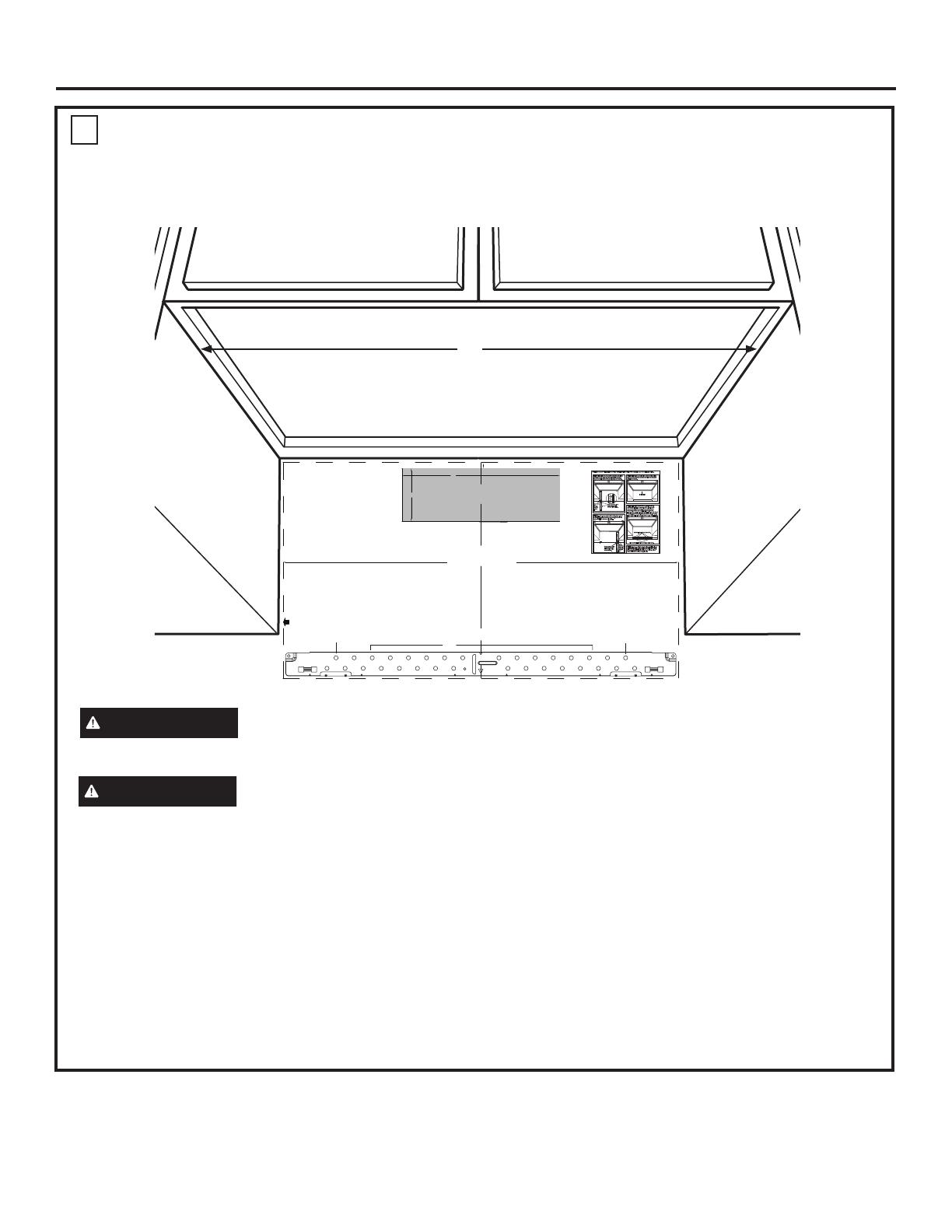
MARCA DE LOS AGUJEROS DE MONTAJE
OPCIÓN 1: USE LA PANTILLA DE PAPEL DE LA PARED TRASERA
ADVERTENCIA
Riesgo de Descarga
Eléctrica. Puede ocasionar lesiones o la muerte.
Deberá tener cuidado de no taladrar sobre cableados
eléctricos dentro de paredes o gabinetes.
Esta Plantilla de la Pared Trasera sirve para ubicar los
agujeros de montaje de la placa de montaje inferior y
para ubicar la salida horizontal del escape.
1. Use un nivel para controlar que la plantilla esté
posicionada de forma correcta.
2. Ubique y marque por lo menos un montaje sobre el
lado izquierdo o derecho de la línea central.
NOTA: Es importante usar por lo menos un tornillo de
madera montado de manera firme en un montaje para
sostener el peso del horno microondas.
3. Marque la ubicación del agujero en la pared usando la
plantilla en los agujeros A y B. Marque al menos una
ubicación de agujero en el área C que se alinee con la
ubicación de un perno. Se debe utilizar un mínimo de
tres agujeros para el montaje.
4. Perfore agujeros en las ubicaciones marcadas. Donde
haya un montaje, haga un agujero de 3/16” para
tornillos de madera. Para aquellos agujeros que no
estén alineados con un montaje, haga agujeros de
5/8” para tornillos con resorte.
NOTA: NO INSTALE LA PLACA DE MONTAJE EN
ESTE MOMENTO.
5. Retire la plantilla de la pared trasera.
D
PRECAUCIÓN
Use guantes para evitar
cortes de dedos en extremos puntiagudos.
30”
CUT HOLE THROUGH REAR WALL FOR EXHAUST ADAPTOR
12"
4"
NOTE: IT IS VERY IMPORTANT TO
READ AND FOLLOW THE DIRECTIONS
IN THE INSTALLATION INSTRUCTIONS
BEFORE PROCEEDING WITH THIS
REAR WALL TEMPLATE.
This Rear Wall Template serves to position the bottom
mounting plate and to locate the horizontal exhaust
outlet.
1. Use a level to check that the template is positioned
accurately.
2. Locate and mark at least one stud on the left or
right side of the centerline.
NOTE:It is important to use at least one wood
screw mounted firmly in a stud to support the weight
of the microwave. Mark two additional, evenly spaced
locations for the supplied toggle bolts.
3. Drill holes in the marked locations. Where there is
a stud, drill a 3/16" hole for wood screws. For holes
that do not line up with a stud, drill 5/8" holes for
toggle bolts.
NOTE::DO NOT INSTALL THE MOUNTING PLATE
AT THIS TIME.
4. Remove the template from the rear wall.
5. Review the Installation Instruction book for your
installation situation.
Darle vuelta a la hoja para consultar la
versión en Español.
CAUTION - IF EXHAUST ADAPTOR IS POSITIONED OUTSIDE
RECOMMENDED DIMENSION, GREASE-LADEN AIR WILL
DISCHARGE INTO HOUSE STRUCTURE
30” MINIMUM WIDTH REQUIRED
REAR WALL TEMPLATE
F. CUT OUT FOR HORIZONTAL
OUTSIDE EXHAUST
Locate and mark holes to align with holes in the
mounting plate.
IMPORTANT:
LOCATE AT LEAST ONE STUD ON EITHER SIDE OF
THE CENTERLINE.
MARK THE LOCATION FOR 2 ADDITIONAL, EVENLY
SPACED TOGGLE BOLTS IN THE MOUNTING PLATE
AREA.
Locate and mark holes to align with holes in the
mounting plate.
IMPORTANT:
LOCATE AT LEAST ONE STUD ON EITHER SIDE OF
THE CENTERLINE.
MARK THE LOCATION FOR 2 ADDITIONAL, EVENLY
SPACED TOGGLE BOLTS IN THE MOUNTING PLATE
AREA.
Trim the rear wall template along the dotted line.
3/8" TO EDGE
C
NOTES:
- 13” Max Cabinet Depth
- 15” deep cabinets require additional steps using
an additional installation kit: JX15BUMP
OPTION 1
OPTION 2
STEP 1: Installer uses bracket to make 2 marks. First
mark is made by using the stampled slot in bracket.
Second mark is made on the ouside edge of bracket.
STEP 3: Installer uses a level to draw a horizontal line
that connects the two marks made with the stamped
slot in the bracket.
STEP 2: Installer moves bracket to the other side of
the cabinets and makes 2 more marks. Marks are the
same as STEP 1, just opposite side.
STEP 4: Installer uses marks to install bracket in
correct position. The bracket is to be installed per
standard requirements (at least one wood screw
mounted in a stud, two additional evenly spaced
locations for toggle bolts). Mark hole location A,B, C and
D by placing the mounting bracket on the wall as shown
in the picture. Hole C and or D must be in a WALL STUD.
STEP 5: Set mounting bracket aside and drill holes at
all marked locations. If there is a stud, drill a 3/16” hole
for wood screws. For holes that do not line up with a
stud, drill a 5/8” hole for a toggle bolt.
Make a mark here, along
inside bottom of the
stamped slot provided.
Make a mark
here,
even with
bottom of
stamped
slot
Make a mark here, along
inside bottom of the
stamped slot provided
(same as Step 1).
Make a
mark here,
even with
bottom of
stamped
slot
Horizontal line
A
C
D
B
Place bracket within the lines created in previous steps.
Mark hole locations for A, B, C, and D.
NOTE: Refer to step C “DETERMINING MOUNTING PLATE LOCATION UNDER YOUR CABINET on page 10 for aligning instructions.
C
A
B


