
Bathroom Exhaust Fan/Fluorescent Light Combination
MODEL: 769RFT
Ventilador de Escape/Luz fluorescente del baño
MODELO: 769RFT
FOR BEST RESULTS
When installing the Exhaust Fan/Light in a new construction
site, install housing during the rough-in construction of the
building. The blower unit and grille should be installed after the
finished ceiling is in place.
To install the Exhaust Fan/Light in an existing finished building
see instructions page 4.
IMPORTANT SAFETY INSTRUCTIONS
WARNING: TO REDUCE THE RISK OF FIRE.
ELECTRIC SHOCK, OR INJURY TO PERSONS,
OBSERVE THE FOLLOWING:
A. Use this unit only in the manner intended by the
manufacturer. If you have questions, contact the
manufacturer.
B. Before servicing or cleaning unit, switch power off
at service panel and lock service panel to prevent
power from being switched on accidentally.
When the service disconnecting means cannot be
locked, securely fasten a prominent warning device,
such as a tag, to the service panel.
CAUTION:
For general ventilating use only. Do not use to
exhaust hazardous or explosive materials and
vapors.
INSTALLATION INSTRUCTIONS
WARNING: TO REDUCE THE RISK OF FIRE,
ELECTRIC SHOCK, OR INJURY TO PERSONS,
OBSERVE THE FOLLOWING:
A. Installation work and electrical wiring must be
done by qualified person(s) in accordance with all
applicable codes and standards, including fire-
rated construction.
B. Sufficient air is needed for proper combustion and
exhausting of gases through the flue (chimney) of
fuel burning equipment to prevent back drafting.
Follow the heating equipment manufacturer's
guideline and safety standards such as those
published by the National Fire Protection
Association (NFPA), and the American Society for
Heating, Refrigeration and Air Conditioning
Engineers (ASHRAE), and the local code
authorities.
C. When cutting or drilling into wall or ceiling, do not
damage electrical wiring and other hidden utilities.
D. Ducted fans must always be vented to the
outdoors.
E. If this unit is to be installed over a tub or shower, it
must be marked as appropriate for the application.
F. NEVER place a switch where it can be reached
from a tub or shower.
•
WARNING: To reduce the risk of fire or electric
shock, do not use this fan with any solid-state
speed control device.
•
Not for use in kitchens.
•
For installation in sloped ceilings up to 12/12 pitch.
•
Ductwork must point up.
• SUITABLE FOR USE OVER A TUB OR
SHOWER WHEN INSTALLED IN A G.F.C.I.
PROTECTED BRANCH CIRCUIT.
• DO NOT INSTALL IN A CEILING INSULATED
TO A VALUE GREATER THAN R-40.
INSTALLATION INSTRUCTIONS
READ & SAVE THESE
INSTRUCTIONS!
INSTRUCCIONES DE INSTALACIÓN
¡LEA Y GUARDE ESTAS
INSTRUCCIONES!
PARA MEJORES RESULTADOS
Cuando está instalando el Ventilador Extractor/Luz en un sitio de
construcción nuevo, instale la cubierta durante la instalación oculta del
inmueble. La unidad del ventilador y la rejilla deben ser instalados después
de que el cielorraso sea acabado.
Para instalar el Ventilador Extractor/Luz en un inmueble acabado, vea las
instrucciones en la página 4.
INSTRUCCIONES DE SEGURIDAD
IMPORTANTES
ADVERTENCIA: PARA REDUCIR EL RIESGO DE
INCENDIO, DESCARGA ELÉCTRICA, O HERIDAS A
PERSONAS, OBSERVE LO SIGUIENTE:
A. Use esta unidad como lo indica el fabricante. Si tiene
preguntas, contacte al fabricante.
B. Antes de hacer mantenimiento o de limpiar la
unidad, apague el interruptor en el panel de servicio
para prevenir que el interruptor se prenda por
casualidad. Cuando los medios para desconectar el
servicio no se puedan asegurar, sujete un emblema
de advertencia prominente, tal como una etiqueta, al
panel de servicio.
ATENCIÓN:
Para uso de ventilación general solamente. No usar
para extraer materiales o vapores peligrosos o
explosivos.
INSTRUCCIONES DE INSTALACIÓN
ADVERTENCIA: RARA REDUCIR EL RIESGO DE
INCENDIO, DESCARGA ELÉCTRICA, O HERIDAS A
PERSONAS, OBSERVE LO SIGUIENTE:
A. El trabajo de instalación e instalación eléctrica debe
ser hecho por persona(s) calificada(s) de acuerdo
con todos los códigos y normas aplicables,
incluyendo la construcción del índice de fuego.
B. Suficiente aire es necesario para la debida
combustión y extracción de gases por el conducto
(chimenea) del equipo que quema combustible para
prevenir que se devuelva la corriente de aire. Siga la
guía y los códigos de seguridad del fabricante de
equipos de calefacción tales como las publicadas
por la Asociación Nacional de Protección de Fuego
(NFPA), y la Asociación Americana para Ingenieros
de Calefacción, Refrigeración y Aire Acondicionado
(ASHRAE), y las autoridades locales.
C. Cuando este cortando o taladrando la pared o el
techo, no le haga daño a los cables eléctricos o a
otras utilidades escondidas.
D. Los ventiladores de conducto siempre deben emitir
hacia afuera.
E. Si esta unidad se va a instalar sobre una tina o una
ducha, debe ser marcada como apropiada para esta
aplicación.
F. NUNCA ponga un interruptor donde se pueda
alcanzar desde una tina o una ducha.
• ADVERTENCIA: Para reducir el riesgo de
incendio o descarga eléctrica, no use este
ventilador con ningún dispositivo de control de
velocidad de estado sólido.
• No es para uso en la cocina.
• Es para instalación en cielorrasos en pendiente de
hasta 12/12 de inclinación.
• La red de conductos debe apuntar para arriba.
• APROPIADO PARA USAR SOBRE UNA TINA O
DUCHA CUANDO SE INSTALA EN UNA RAMA
DE CIRCUITO PROTEGIDO DE A.G.F.C.I.
• NO INSTALE EN UN CIELORRASO AISLADO
CON UN VALOR MAYOR A R-40.
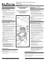
FIGURE 1
D
UCT COLLAR
COLLAR DEL DUCTO
HOUSING
CUBIERTA
SLOTS
RANURAS
TABS
LENGUETAS
GRILLE
PARRILLA
REFLECTOR
REFLECTOR
LENS
LENTE
POWER
UNIT/BLOWER
ASSEMBLY
ENSAMBLE
DE LA
UNIDADE
POTENCIA/
VENTILADOR
TO REGISTER THIS PRODUCT, VISIT WWW.NUTONE.COM
PARA COLOCAR ESTE PRODUCTO, VISITE WWW.NUTONE.COM

PLANNING DUCTWORK AND WIRING
DUCTWORK
1. Use 4" round duct.
2. Plan to run duct from the fan's discharge opening
to the outside. For best fan performance, make
duct run as short as possible and use minimum
number of elbows.
3. Use optional NuTone ducting accessories as
needed (refer to NuTone's catalog for a complete
listing of optional accessories).
WIRING
Plan to run 120vAC house wiring (with ground) from
a power source, through a standard wall switch or an
optional NuTone double FAN/LIGHT switch, to the
junction box in the Fan-Light's housing.
INSTALLATION IN A NEW
CONSTRUCTION SITE
PREPARATION
1. Unplug the power unit.
2. Refer to Figure 1. Remove power unit/blower
assembly from the housing. Remove screw and
pull power unit assembly tabs out of slots in
housing. Set unit aside until needed.
3. Remove one of the wiring knockouts from housing.
MOUNTING THE HOUSING
USING SIDE MOUNTING TABS
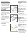
Refer to Figure 2.
1. Locate housing next to ceiling joist.
2. Use wood screws (not provided) to loosely attach
housing to ceiling joist through keyhole slots in
mounting tabs.
3. Adjust housing so that it will be flush with the
finished ceiling.
4. When housing is properly adjusted, tighten screws
in slots.
USING HANGER BARS
(Hanger bars sold separately, order model HB4)
Refer to Figure 3.
1. Insert hanger bars in slots provided in housing.
2. Locate fan housing between ceiling joists so that
bottom of fan housing is even with the planned
finished ceiling.
3. Use screws or nails to secure mounting brackets
to ceiling joists.
INSTALLING DUCTWORK
1. Refer to Figure 1. Place duct collar over flanges
at discharge opening of fan. Secure collar by
snapping tabs into slots in flanges.
2. Refer to Figure 4. Run 4" round duct from outside
to fan's discharge opening.
3. Connect duct to duct collar.
F
IGURE 2
FIGURE 3
FIGURE 4
WIRING KNOCKOUTS
P
LACAS TEMPORALES
DEL ALAMBRADO
MOUNTING TABS
LENGUETAS DEL
MONTAJE
ROOF CAP
TAPAS DE RAIZ
90° ELBOW
CODO DE 90 GRADOS
4" DIAMETER
DUCT
CONDUCTOR
DE DIAMETRO
DE 10,25 CM
(4 PULGADAS)
HANGER BARS
(SOLD SEPARATELY)
BARRAS
COLGANTES
(SE VENDEN POR
SEPARADO)
PLANEANDO LA RED DE CONDUCTOS Y
EL ALAMBRADO
RED DE CONDUCTOS
1. Use un conducto redondo de 10 centímetros
(4 pulgadas).
2. Planee poner un conducto desde la apertura de
descarga del ventilador hacia afuera. Para que el
ventilador funcione a su mejor rendimiento, haga
que el conducto sea lo mas corto posible y use el
menor número de codos.
3. Use los accesorios de conductos opcionales de
NuTone como sea necesario (vea al catálogo de
NuTone para una lista completa de los accesorios
opcionales).
ALAMBRADO
Planee poner un alambrado de casa 120vAC
(conectados a tierra) de una fuente de energía, por
medio de un interruptor de pared estándar o por un
interruptor doble VENTILADOR/LUZ opcional de
NuTone, a la caja de empalmes en la cubierta del
Ventilador-Luz.
INSTALACIÓN EN UN SITIO DE
CONSTRUCCIÓN NUEVO
PREPARACIÓN
1. Desconecte la unidad de poder.
2. Vea la figura 1. Remueva la unidad de
poder/conjunto del ventilador de la cubierta. Quite
el tornillo y saque las lengüetas del conjunto de la
unidad de poder fuera de las ranuras de la
cubierta. Ponga la unidad a un lado hasta que la
necesite.
3. Remueva uno de troqueles del alambrado de la
cubierta.
MONTAJE DEL ALMACENAJE
USANDO LENGÜETAS DE MONTAJE DEL LADO
Vea la figura 2.
1. Localice la cubierta al lado de la viga del
cielorraso.
2. Use dos tornillos para madera (no son
suministrados) para ligar ligeramente la cubierta a
la viga del cielorraso por medio de la ranura de
bocallave en las lengüetas de soporte.
3. Ajuste la cubierta para que esté enrasado con el
cielorraso acabado.
4. Cuando la cubierta esté ajustada
apropiadamente, apriete los tornillos en las
ranuras.
USANDO LAS BARRAS PARA COLGAR
(Las barras para colgar se venden por separado,
ordene el modelo HB4)
Vea la figura 3.
1. Introduzca las barras para colgar en las ranuras
suministradas en la cubierta.
2. Ponga el almacenaje del ventilador entre las
vigas del cielorraso de tal forma que la parte
inferior de la cubierta del ventilador quede
uniforme con el cielorraso acabado planeado.
3. Use tornillos o clavos para fijar los soportes del
montaje a las vigas del cielorraso.
INSTALANDO RED DE CONDUCTOS
1. Vea la figura 1. Coloque el collar del conducto
sobre las bridas en la apertura de descargue del
ventilador. Fije el collar ajustando las lengüetas
en las ranuras de las bridas.
2. Vea la figura 4. Ponga un conducto redondo de
10 centímetros (4 pulgadas) desde afuera hasta
la apertura de descargue del ventilador.
3. Conecte el conducto al collar del conducto.

WIRING
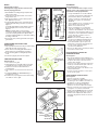
Refer to Figures 5 and 6.
All wiring must comply with local codes and unit
must be properly grounded.
1. Run 120vAC house wiring (with ground) from wall
switch to fan location.
2. Insert and secure an approved box connector into
wiring entrance hole.
3. Pull wires through box connector and into junction
box. Tighten box connector.
4. If a single switch will be used to control both the fan
and the light, make wiring connections as shown in
Figure 5.
If a double switch will be used for separate control of
the fan and light, make connections as shown in
Figure 6.
NOTE: If a double switch is used, the wiring
connections determine which receptacle will be used
for the fan motor plug and which receptacle will be
used for the light plug. Make note of this when making
the wiring connections.
5. Connect the green (or bare) ground wire to the green
ground lead.
POWER/BLOWER UNIT INSTALLATION
Refer to Figure 7.
1. Place power/blower unit into housing so that mounting
plate's tabs insert into slots in housing.
2. Press other end of mounting plate down until it is
firmly seated over scroll and plug-in receptacles.
3. Secure mounting plate to housing with provided
screw.
4. Insert motor plug into junction box receptacle.
COMPLETING INSTALLATION
Refer to Figure 8.
1. Place reflector into grille.
2. Align grille/reflector assembly with housing and
insert light plug into receptacle in junction box.
3. Remove acorn nut from threaded stud on
mounting plate.
4. Place reflector over stud and secure with acorn
nut.
5. Install lamp NEMA type CFQ13W/G24q (not
provided) into socket.
6. Install lens by squeezing both sides and inserting
lens tabs into slots in grille.
S
INGLE SWITCH CONTROL
CONTROL DE UN SOLO
I
NTERRUPTOR
DOUBLE SWITCH CONTROL
CONTROL DE DOS
INTERRUPTORES
WHITE
B
LANCO
WHITE
BLANCO
BLACK
NEGRO
120vAC
120v AC
GROUND
D
I TIERRA
B
LACK
N
EGRO
BLACK
NEGRO
120vAC
120v AC
GROUND
D
I TIERRA
ALAMBRADO
Vea las figuras 5 y 6
Todo el alambrado debe cumplir con los
códigos locales y las unidades deben estar
conectadas a tierra apropiadamente.
1. Ponga el alambrado de casa de 120v CA
(conectado a tierra) desde el interruptor de
pared hasta la ubicación del ventilador.
2. Inserte y asegure un conectador de caja
aprobado en el agujero de entrada del
alambrado.
3. Jale los alambres por el conectador de caja
y hacia adentro de la caja de registro.
Apriete el conectador de caja.
4. Si solo un interruptor se va a usar para
controlar el ventilador y la luz, haga las
conexiones del alambrado como se muestra
en la figura 5. Si un interruptor doble se va a
usar para el control separado del ventilador
y la luz, haga las conexiones como se
muestra en la figura 6.
NOTA: Si se usa un interruptor doble, las
conexiones de alambrado determinan que
receptor será usado para el enchufe del
motor del ventilador y que receptor será
usado para el enchufe de la luz. Haga nota
de esto cuando está haciendo las
conexiones de alambrado.
5. Conecte el cable verde (o desnudo) de tierra
al conductor a tierra verde.
INSTALACIÓN DE LA UNIDAD DE
PODER/VENTILADOR
Vea la Figura 7.
1. Coloque la unidad de poder/ventilador a la
cubierta de tal forma en que las lengüetas de
las placas de montaje se inserten en las
ranuras de la cubierta.
2. Presione el otro lado de la placa de montaje
hasta que esté firmemente fijado sobre los
módulos de control y de enchufe.
3. Fije la placa de montaje a la cubierta con el
tornillo suministrado.
4. Inserte el enchufe del motor en el receptor
de la caja de registro.
COMPLETANDO LA INSTALACIÓN
Vea la Figura 8.
1. Coloque el reflector en parrilla.
2. Alinee a asamblea de grille/reflector con el
enchufe ligero de la cubierta y del relleno en
receptáculo en caja de ensambladura.
3. Quite la tuerca de la bellota del perno
prisionero roscado en la placa de montaje.
4. Coloque el reflector sobre el perno prisionero
y asegúrelo con la tuerca de la bellota.
5. Instale el tipo CFQ13W/G24q de la nema de
la lámpara (no proporcionado) en el zócalo.
6. Instale la lente exprimiendo ambos lados e
insertando lengüetas de la lente en ranuras
en parrilla.
SLOTS
RANURAS
MOUNTING PLATE
PLACA DE MONTAJE
MOTOR PLUG
ENCHUDE DEL
MOTOR
INSERT TABS
INTO SLOTS
INSERTE LAS
LENGÜETAS EN
RANURAS
GRILLE
PARRILLA
LAMP SOCKET
ENCHUFE DE
LAMPARA
REFLECTOR
REFLECTOR
LIGHT PLUG
ENCHUFE DE LUZ
FAN PLUG
ENCHUFE DEL VENTILADOR
FIGURE 7
FIGURE 8
FIGURE 5
FIGURE 6
BLUE
AZUL
BLUE
AZUL

PLANNING
Installing a bathroom exhaust fan-light in a finished house requires at least a
small accessible area (attic or crawl space) above the planned installation
location.
Review “INSTALLATION IN A NEW CONSTRUCTION SITE” AND FOLLOW
ALL INSTRUCTIONS WHICH APPLY TO YOUR INSTALLATION.
LOCATION: Locate fan-light next to a ceiling joist.
WIRING AND DUCTING: Refer to Figures 5 and 6 for wiring and to
Figure 4 for ducting. Plan ducting and wiring before proceeding with
installation.
CAUTION: Check area above planned location to be sure that:
(1) Ducting can be installed or that area is sufficient for proper venting.
The ceiling joists should run toward an outside wall.
(2) Wiring can be run to the planned location.
(3) No wiring or other obstruction might interfere with installation.
INSTALLATION
1. The fan light must be mounted to a ceiling joist. Decide where you want to
locate the fan-light and then determine if there is a ceiling joist near.
LOCATING JOIST: Lightly tap the ceiling. A hollow sound means no
joists, a solid sound means a joist is present. To be sure you have located
a joist, drill a small hole (
1
⁄16") and probe into the ceiling with a wire. Leave
wire in hole to help locate it in the attic or crawl space.
2. Locate hole in attic or crawl space. Make sure hole is within 9" of joist.
3. From below, saw a line from hole to joist.
4. Using the housing as a template, mark the ceiling for the cutout. Cutout
dimensions: 9
1
⁄8" x 9
1
⁄8". One side of cutout must be right next to joist.
5. Make cutout along marked line.
6. In attic or crawl space, run 4" round duct from outside to cutout location.
7. Run wiring to cutout location.
8. Place housing into cutout and secure housing to joist. Make sure housing
is flush with finished ceiling. Connect duct.
9. From below, connect wiring. Install power/blower unit, grille/reflector
assembly, fluorescent lamp and lens.
INSTALLATION IN EXISTING CONSTRUCTION
INSTALACION EN UNA CONSTRUCCION EXISTENTE
PLANIFICACIÓN
Para instalar un ventilador extractor/luz de baño en una casa acabada, se
necesita por lo menos un área pequeña accesible (un ático o un espacio
abierto) encima del sitio de instalación planeada.
Revise la "INSTALACIÓN EN UN LUGAR DE CONSTRUCCIÓN NUEVA" Y
SIGA TODAS LAS INSTRUCCIONES QUE SE APLICAN A SU
INSTALACIÓN.
UBICACIÓN: Coloque el ventilador extractor/luz al lado de una viga del
cielorraso.
ALAMBRADO Y CONDUCTOS: Vea las Figuras 5 y 6 para el alambrado
y la figura 4 para los conductos. Planee los conductos y el alambrado
antes de proceder con la instalación.
CUIDADO: Revise el área sobre el sitio planeado para asegurarse de
que:
(1) Los conductos se pueden instalar si el área es suficiente grande para
tener la ventilación apropiada. La viga del cielorraso debe ir hacia un
muro de afuera.
(2) El alambrado se puede llevar al sitio planeado.
(3) Ningún alambrado u otra obstrucción pueda interferir con la
instalación.
INSTALACIÓN
1. El ventilador/luz debe estar montado a una viga del cielorraso. Decida
donde quiere localizar el ventilador/luz y luego determine si hay una viga
del cielorraso cercana. LOCALIZANDO LA VIGA: Ligeramente golpee el
cielorraso. Un sonido hueco quiere decir que no hay viga, un sonido sólido
quiere decir que si hay una viga presente. Para asegurarse de que ha
encontrado una viga, taladre un hoyo pequeño 1.6 mm (0,06 pulgada) y
examine dentro del cielorraso con un alambre. Deje el alambre en el hoyo
para que le ayude a localizarlo en el ático o en el espacio abierto.
2. Localice el hoyo en el ático o en el espacio abierto. Asegúrese de que el
hoyo esté a 23 cm (9.1 pulgadas) de la viga.
3. Desde abajo, corte con serrucho una línea del hoyo a la viga.
4. Usando la cubierta como plantilla, marque el cielorraso para el recorte.
Dimensiones del recorte: 23 cm por 23 cm (9,1 pulgadas por 9.1
pulgadas). Un lado del recorte debe estar junto a la viga.
5. Haga el recorte a lo largo de la línea marcada.
6. En el ático o el espacio abierto, ponga un conducto redondo de 10,3 cm (4
pulgadas) desde afuera, hasta el lugar del recorte.
7. Lleve el alambrado hasta el lugar del recorte.
8. Coloque la cubierta en el recorte y fije la cubierta a la viga. Asegúrese de
que la cubierta esté a nivel con el cielorraso acabado. Conecte el
conducto.
9. Desde abajo, conecte el alambrado. Instale la unidad de poder/ventilador,
conjunto de rejilla/reflector, lámpara fluorescente y lente.

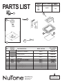
NOTE: Always order by
current part number
Broan-NuTone LLC
Hartford, Wisconsin
www.nutone.com
888-336-3948
763RLN & 769RL I.I.
769RFT
Rev.
JAN.
2008
R01
FAN
EFFECTIVE
DATE
PRODUCT
GROUP
MODEL NUMBER
9
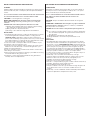
PARTSLIST
8
3
4
5
1
6
7
10
0503B
1 POWER UNIT ASSEMBLY 769RFT 0504B-000
0504B
89914
2 BLOWER WHEEL 769RFT 82403-000
68739
REFLECTOR, LAMPHOLDER
3 89765 769RFT 1023B-000
& BALLAST
4 30652 DUCT ADAPTER ASSEMBLY 769RFT 101183000
5 85316 GRILLE 769RFT 1100802
6 89108 LENS 769RFT 99111408
7 16133 ACORN NUT 769RFT 99260575
8 61326 FAN RECEPTACLE 769RFT 99271654
9 82304 LIGHT RECEPTACLE 769RFT 99270981
10 1022B STUD & NUT ASSY 769RFT 1022B-000
CURRENT
ORIGINAL
REPLACEMENT
REF.
PART NO.
PART DESCRIPTION MODEL USED ON
PART NO.
2

Product
specifications subject to change without notice.
Printed in China., Rev. E 12/18, Part No. 101258
Las especificaciones del producto están sujetas a cambiar sin aviso.
Impreso en China., Rev. E 12/18, Parte No. 101258
One Year Limited Warranty
WARRANTY OWNER: Broan-NuTone warrants to the original consumer purchaser of its products that such products will be free from defects in materials or
workmanship for a period of one (1) year from the date of original purchase. THERE ARE NO OTHER WARRANTIES, EXPRESS OR IMPLIED, INCLUDING, BUT
NOT LIMITED TO, IMPLIED WARRANTIES OF MERCHANTABILITY OR FITNESS FOR A PARTICULAR PURPOSE.
During this one year period, Broan-NuTone will, at its option, repair or replace, without charge, any product or part which is found to be defective under normal use
and service. THIS WARRANTY DOES NOT EXTEND TO FLUORESCENT LAMP STARTERS OR TUBES, FILTERS, DUCT, ROOF CAPS, WALL CAPS AND OTHER
ACCESSORIES FOR DUCTING. This warranty does not cover (a) normal maintenance and service or (b) any products or parts which have been subject to misuse,
negligence, accident, improper maintenance or repair (other than by Broan-NuTone), faulty installation or installation contrary to recommended installation instructions.
The duration of any implied warranty is limited to the one year period as specified for the express warranty. Some states do not allow limitation on how long an implied
warranty lasts, so the above limitation may not apply to you.
BROAN-NUTONE’S OBLIGATION TO REPAIR OR REPLACE, AT BROAN-NUTONE’S OPTION, SHALL BE THE PURCHASER’S SOLE AND EXCLUSIVE
REMEDY UNDER THIS WARRANTY. BROAN-NUTONE SHALL NOT BE LIABLE FOR INCIDENTAL, CONSEQUENTIAL OR SPECIAL DAMAGES ARISING OUT
OF OR IN CONNECTION WITH PRODUCT USE OR PERFORMANCE. Some states do not allow the exclusion or limitation of incidental or consequential damages,
so the above limitation or exclusion may not apply to you. This warranty gives you specific legal rights, and you may also have other rights, which vary from state to
state. This warranty supersedes all prior warranties.
WARRANTY SERVICE: To qualify for warranty service, you must (a) notify Broan-NuTone at the address or telephone number below, (b) give the model
number and part identification and (c) describe the nature of any defect in the product or part. At the time of requesting warranty service, you must present
evidence of the original purchase date.
Date of Installation
Builder or Installer
Model No. and Product Description
IF
YOU NEED ASSISTANCE OR SERVICE - CONTACT:
Broan Hartford, Wisconsin www.nutone.com 888-336-3948
Venmar Ventilation ULC Drummondville (Quebec), Canada www.nutone.ca 877-896-1119
Rev. 08/2007
Garantía limitada de un año
GARANTÍA DEL PROPIETARIO: Broan-NuTone garantiza al comprador consumidor original de sus productos por un período de un (1) año desde la fecha original de
compra, que tales productos están libres de defectos en material y mano de obra. NO HAY OTRAS GARANTÍAS, EXPRESAS O IMPLÍCITAS, INCLUYENDO,
ENTRE OTRAS, GARANTÍAS IMPLÍCITAS DE COMERCIALIZACIÓN O ADAPTABLES A UN PROPÓSITO EN PARTICULAR.
Durante este período de un año, Broan-NuTone reparará o reemplazará a su opción y sin costo, cualquier producto o parte que se encuentre defectuoso bajo
condiciones normales de uso y servicio. ESTA GARANTÍA NO CUBRE A LOS ARRANCADORES PARA LÁMPARAS FLUORESCENTES O A LOS TUBOS
FLUORESCENTES, FILTROS, CONDUCTOS, TAPAS DE TECHO, TAPAS DE PARED Y OTROS ACCESORIOS PARA CANALIZACIÓN. Esta garantía no cubre (a)
Mantenimiento y servicios normales, ni (b) Productos o partes sujetos al mal uso, negligencia, accidente, mantenimiento inadecuado o reparaciones (por otros ajenos
a Broan-NuTone), instalación defectuosa o una instalación contraria a las instrucciones de instalación recomendadas.
La duración de cualquier garantía implícita está limitada a un periodo de un año según se especifica en la garantía expresa. Algunos estados no permiten limitación en
cuanto a la duración de una garantía implícita, por lo que la limitación arriba indicada puede que no se apliqué a usted.
LA OBLIGACIÓN DE BROAN-NUTONE DE REPARAR O REEMPLAZAR A SU OPCIÓN, SERÁ EL ÚNICO Y EXCLUSIVO RECURSO QUE TENDRÁ EL
COMPRADOR BAJO ESTA GARANTÍA. BROAN-NUTONE NO SERÁ RESPONSABLE POR DAÑOS INCIDENTALES, CONSECUENTES O ESPECIALES QUE
RESULTEN A CONSECUENCIA O SEAN INDEPENDIENTES DEL USO O DESEMPEÑO DEL PRODUCTO. Algunos estados no permiten la exclusión o limitación
de daños incidentales o consecuentes, de modo que la limitación o exclusión arriba indicada pueda que no se aplique a usted. Esta garantía le proporciona derechos
legales específicos, y usted podría tener otros derechos, los cuales varían de un estado a otro. Esta garantía reemplaza a todas las garantías anteriores.
SERVICIO DE GARANTÍA: Para tener derecho al servicio de garantía, usted debe (a) notificar a Broan-NuTone a la dirección o al número de teléfono
indicado abajo, (b) indicar el número de modelo y la identificación de la parte y (c) describir la naturaleza de cualquier defecto en el producto o parte. Al
momento de solicitar el servicio por la garantía, usted debe presentar un comprobante de la fecha original de compra.
Fecha de la instalación
Constructor o instalador
Número de modelo y descripción del producto
SI NECESITA ASISTENCIA O SERVICIO - COMUNÍQUESE
A:
Broan Hartford, Wisconsin www.nutone.com 888-336-3948
Venmar Ventilation ULC Drummondville (Quebec), Canada www.nutone.ca 877-896-1119
Rev. 08/2007
-
 1
1
-
 2
2
-
 3
3
-
 4
4
-
 5
5
-
 6
6


En otros idiomas
- English: NuTone 769RFT Installation guide
Documentos relacionados
-
NuTone 769RFT Guía de instalación
-
-
-
-
NuTone 769RL Manual de usuario
-
-
-
-
NuTone 8664RP Guía de instalación
-