MINN KOTA MINN-KOTA 1363885 EO Transom Mount Electric Outboard Motor Manual de usuario
- Tipo
- Manual de usuario

EO
TRANSOM-MOUNT ELECTRIC OUTBOARD MOTOR
USER MANUAL

Model: _________________________________________________________________________________________________________________________
Serial Number: _______________________________________________________________________________________________________________
Purchase Date: _______________________________________________________________________________________________________________
Store Where Purchased: ____________________________________________________________________________________________________
NOTE: Do not return your Minn Kota motor to your retailer. Your retailer is not authorized to repair or replace this unit. You may obtain service
by: calling Minn Kota at (800) 227-6433; returning your motor to the Minn Kota Factory Service Center; sending or taking your motor to any
Minn Kota authorized service center. A list of authorized service centers is available on our website, at minnkotamotors.com. Please include proof of
purchase, serial number and purchase date for warranty service with any of the above options.
Please thoroughly read this user manual. Follow all instructions and heed all safety and cautionary notices below. Use of this motor is only
permitted for persons that have read and understood these user instructions. Minors may use this motor only under adult supervision.
ATTENTION: Never run the motor out of the water, as this may result in injuries from the rotating propeller. The motor should be disconnected from
the power source when it is not in use or is off the water. When connecting the power-supply cables of the motor to the battery, ensure that they are
not kinked or subject to chafe and route them in such a way that persons cannot trip over them. Before using the motor make sure that the insulation
of the power cables is not damaged. Disregarding these safety precautions may result in electric shorts of battery(s) and/or motor. Always disconnect
motor from battery(s) before cleaning or checking the propeller. Avoid submerging the complete motor as water may enter the lower unit through
control head and shaft. If the motor is used while water is present in the lower unit considerable damage to the motor can occur. This damage will not
be covered by warranty.
CAUTION: Take care that neither you nor other persons approach the turning propeller too closely, neither with body parts nor with objects. The
motor is powerful and may endanger or injure you or others. While the motor is running watch out for persons swimming and for fl oating objects.
Persons whose ability to run the motor or whose reactions are impaired by alcohol, drugs, medication, or other substances are not permitted to use
this motor. This motor is not suitable for use in strong currents. The constant noise pressure level of the motor during use is less than 70dB(A). The
overall vibration level does not exceed 2,5m/sec2.
THANK YOU
Thank you for choosing Minn Kota. We believe that you should spend more time fi shing and less time positioning your
boat. That’s why we build the smartest, toughest, most intuitive motors on the water. Every aspect of a Minn Kota motor is
thought out and rethought until it’s good enough to bear our name. Countless hours of research and testing provide you the
Minn Kota advantage that can truly take you “Anywhere. Anytime.” We don’t believe in shortcuts. We are Minn Kota. And we are
never done helping you catch more fi sh.
REMEMBER TO KEEP YOUR RECEIPT AND IMMEDIATELY REGISTER YOUR MOTOR.
A registration card is enclosed or you can complete registration on our website at minnkotamotors.com.
LOCATING YOUR SERIAL NUMBER
Your Minn Kota 11-character serial number is very important. It helps to determine the specifi c model and year of manufacture. When contacting
Consumer Service or registering your product, you will need to know your product’s serial number. We recommend that you write the serial number
down in the space provided below so that you have it available for future reference.
CE MASTER USER MANUAL (FOR CE/C-TICK CERTIFIED MODELS)
Conforms to 89/336/EEC (EMC) under standards EN 55022A, EN 50082-2 since 1996 LN V9677264
2 | minnkotamotors.com ©2015 Johnson Outdoors Marine Electronics, Inc.
The serial number on your EO is located under
the tiller handle.
Made by Minn Kota
Johnson Outdoors
Marine Electronics, Inc.
121 Power Drive
Mankato, MN 56001 USA
Outboard Motors
Produced in 2015
EO - 1/2 HP
MODEL 1363880
SER NO M365 MK12345
EXAMPLE

minnkotamotors.com | 3
©2015 Johnson Outdoors Marine Electronics, Inc.
TABLE OF CONTENTS
Two-Year Limited Warranty 4
Features 5
Installation 6
Battery & Wiring Installation 7-8
Boat Rigging & Product Installation 7
Conductor Gauge and Circuit Breaker Sizing Table 7
Push-to-Test Battery Meter 7
Selecting the Correct Batteries 8
Connecting the Batteries 8
Motor Wiring Diagram 9
Using and Adjusting the Motor 10-11
Adjusting the Depth of the Motor 10
Adjusting the Steering 10
Adjusting the Bracket 11
Adusting the Twist Tiller 11
Controlling Speed & Direction with the Tiller 10
Stowing the Motor 11
Service & Maintenance 12
Propeller Replacement 12
General Maintenance 12
Troubleshooting & Repair 13
Parts Diagram 14
Parts List 15
Compliance Statements 16
Notes 17

WARRANTY ON MINN KOTA EO ELECTRIC OUTBOARD MOTORS
Johnson Outdoors Marine Electronics, Inc. (“JOME”) extends the following limited warranty to the original retail purchaser only. Warranty coverage is not
transferable.
MINN KOTA LIMITED TWO-YEAR WARRANTY ON THE ENTIRE PRODUCT
JOME warrants to the original retail purchaser only that the purchaser’s new Minn Kota primary propulsion motor will be materially free from defects in materials
and workmanship appearing within two (2) years after the date of purchase. JOME will (at its option) either repair or replace, free of charge, any parts found by
JOME to be defective during the term of this warranty. Such repair, or replacement shall be the sole and exclusive liability of JOME and the sole and exclusive
remedy of the purchaser for breach of this warranty.
MINN KOTA LIMITED LIFETIME WARRANTY ON COMPOSITE SHAFT
JOME warrants to the original retail purchaser only that the composite shaft of the purchaser’s Minn Kota motor will be materially free from defects in materials
and workmanship appearing within the original purchaser’s lifetime. JOME will provide a new composite shaft, free of charge, to replace any composite shaft
found by JOME to be defective during the term of this warranty. Providing a new composite shaft shall be the sole and exclusive liability of JOME and the
sole and exclusive remedy of the purchaser for breach of this warranty; and purchaser shall be responsible for installing, or for the cost of labor to
install, any new composite shaft provided by JOME.
EXCLUSIONS & LIMITATIONS
This limited warranty does not apply to products that have been used commercially or for rental purposes. This limited warranty does not cover normal wear
and tear, blemishes that do not aff ect the operation of the product, or damage caused by accidents, abuse, alteration, modifi cation, shipping damages, acts
of God, negligence of the user or misuse, improper or insuffi cient care or maintenance. DAMAGE CAUSED BY THE USE OF OTHER REPLACEMENT
PARTS NOT MEETING THE DESIGN SPECIFICATIONS OF THE ORIGINAL PARTS WILL NOT BE COVERED BY THIS LIMITED WARRANTY.
The cost of normal maintenance or replacement parts which are not in breach of the limited warranty are the responsibility of the purchaser. Prior to using
products, the purchaser shall determine the suitability of the products for the intended use and assumes all related risk and liability. Any assistance JOME
provides to or procures for the purchaser outside the terms, limitations or exclusions of this limited warranty will not constitute a waiver of the terms, limitations
or exclusions, nor will such assistance extend or revive the warranty. JOME will not reimburse the purchaser for any expenses incurred by the purchaser
in repairing, correcting or replacing any defective products or parts, except those incurred with JOME’s prior written permission. JOME’S AGGREGATE
LIABILITY WITH RESPECT TO COVERED PRODUCTS IS LIMITED TO AN AMOUNT EQUAL TO THE PURCHASER’S ORIGINAL PURCHASE
PRICE PAID FOR SUCH PRODUCT.
MINN KOTA SERVICE INFORMATION
To obtain warranty service in the U.S., the product believed to be defective, and proof of original purchase (including the date of purchase), must be presented
to a Minn Kota Authorized Service Center or to Minn Kota’s factory service center in Mankato, MN. Any charges incurred for service calls, transportation or
shipping/freight to/from the Minn Kota Authorized Service Center or factory, labor to haul out, remove, re-install or re-rig products removed for warranty service,
or any other similar items are the sole and exclusive responsibility of the purchaser. Products purchased outside of the U.S. must be returned prepaid with
proof of purchase (including the date of purchase and serial number) to any Authorized Minn Kota Service Center in the country of purchase. Warranty service
can be arranged by contacting a Minn Kota Authorized Service Center or by contacting the factory at 1-800-227-6433 or email service@minnkotamotors.com.
Products repaired or replaced will be warranted for the remainder of the original warranty period [or for 90 days from the date of repair
or replacement, whichever is longer]. For any product that is returned for warranty service that JOME fi nds to be not covered by or not
in breach of this limited warranty, there will be a billing for services rendered at the prevailing posted labor rate and for a minimum of at
least one hour.
NOTE: Do not return your Minn Kota product to your retailer. Your retailer is not authorized to repair or replace products.
THERE ARE NO EXPRESS WARRANTIES OTHER THAN THESE LIMITED WARRANTIES. IN NO EVENT SHALL ANY IMPLIED
WARRANTIES INCLUDING ANY IMPLIED WARRANTIES OF MERCHANTABILITY OR FITNESS FOR PARTICULAR PURPOSE, EXTEND
BEYOND THE DURATION OF THE RELEVANT EXPRESS LIMITED WARRANTY. IN NO EVENT SHALL JOME BE LIABLE FOR PUNITIVE,
INDIRECT, INCIDENTAL, CONSEQUENTIAL OR SPECIAL DAMAGES. Without limiting the foregoing, JOME assumes no responsibility for
loss of use of product, loss of time, inconvenience or other damage.
Some states do not allow limitations on how long an implied warranty lasts or the exclusion or limitation of incidental or consequential damages, so the above
limitations and/or exclusions may not apply to you. This warranty gives you specifi c legal rights and you may also have other legal rights which vary from state
to state.
4 | minnkotamotors.com ©2015 Johnson Outdoors Marine Electronics, Inc.
TWO-YEAR LIMITED WARRANTY

WARRANTY ON MINN KOTA EO ELECTRIC OUTBOARD MOTORS
Johnson Outdoors Marine Electronics, Inc. (“JOME”) extends the following limited warranty to the original retail purchaser only. Warranty coverage is not
transferable.
MINN KOTA LIMITED TWO-YEAR WARRANTY ON THE ENTIRE PRODUCT
JOME warrants to the original retail purchaser only that the purchaser’s new Minn Kota primary propulsion motor will be materially free from defects in materials
and workmanship appearing within two (2) years after the date of purchase. JOME will (at its option) either repair or replace, free of charge, any parts found by
JOME to be defective during the term of this warranty. Such repair, or replacement shall be the sole and exclusive liability of JOME and the sole and exclusive
remedy of the purchaser for breach of this warranty.
MINN KOTA LIMITED LIFETIME WARRANTY ON COMPOSITE SHAFT
JOME warrants to the original retail purchaser only that the composite shaft of the purchaser’s Minn Kota motor will be materially free from defects in materials
and workmanship appearing within the original purchaser’s lifetime. JOME will provide a new composite shaft, free of charge, to replace any composite shaft
found by JOME to be defective during the term of this warranty. Providing a new composite shaft shall be the sole and exclusive liability of JOME and the
sole and exclusive remedy of the purchaser for breach of this warranty; and purchaser shall be responsible for installing, or for the cost of labor to
install, any new composite shaft provided by JOME.
EXCLUSIONS & LIMITATIONS
This limited warranty does not apply to products that have been used commercially or for rental purposes. This limited warranty does not cover normal wear
and tear, blemishes that do not aff ect the operation of the product, or damage caused by accidents, abuse, alteration, modifi cation, shipping damages, acts
of God, negligence of the user or misuse, improper or insuffi cient care or maintenance. DAMAGE CAUSED BY THE USE OF OTHER REPLACEMENT
PARTS NOT MEETING THE DESIGN SPECIFICATIONS OF THE ORIGINAL PARTS WILL NOT BE COVERED BY THIS LIMITED WARRANTY.
The cost of normal maintenance or replacement parts which are not in breach of the limited warranty are the responsibility of the purchaser. Prior to using
products, the purchaser shall determine the suitability of the products for the intended use and assumes all related risk and liability. Any assistance JOME
provides to or procures for the purchaser outside the terms, limitations or exclusions of this limited warranty will not constitute a waiver of the terms, limitations
or exclusions, nor will such assistance extend or revive the warranty. JOME will not reimburse the purchaser for any expenses incurred by the purchaser
in repairing, correcting or replacing any defective products or parts, except those incurred with JOME’s prior written permission. JOME’S AGGREGATE
LIABILITY WITH RESPECT TO COVERED PRODUCTS IS LIMITED TO AN AMOUNT EQUAL TO THE PURCHASER’S ORIGINAL PURCHASE
PRICE PAID FOR SUCH PRODUCT.
MINN KOTA SERVICE INFORMATION
To obtain warranty service in the U.S., the product believed to be defective, and proof of original purchase (including the date of purchase), must be presented
to a Minn Kota Authorized Service Center or to Minn Kota’s factory service center in Mankato, MN. Any charges incurred for service calls, transportation or
shipping/freight to/from the Minn Kota Authorized Service Center or factory, labor to haul out, remove, re-install or re-rig products removed for warranty service,
or any other similar items are the sole and exclusive responsibility of the purchaser. Products purchased outside of the U.S. must be returned prepaid with
proof of purchase (including the date of purchase and serial number) to any Authorized Minn Kota Service Center in the country of purchase. Warranty service
can be arranged by contacting a Minn Kota Authorized Service Center or by contacting the factory at 1-800-227-6433 or email service@minnkotamotors.com.
Products repaired or replaced will be warranted for the remainder of the original warranty period [or for 90 days from the date of repair
or replacement, whichever is longer]. For any product that is returned for warranty service that JOME fi nds to be not covered by or not
in breach of this limited warranty, there will be a billing for services rendered at the prevailing posted labor rate and for a minimum of at
least one hour.
NOTE: Do not return your Minn Kota product to your retailer. Your retailer is not authorized to repair or replace products.
THERE ARE NO EXPRESS WARRANTIES OTHER THAN THESE LIMITED WARRANTIES. IN NO EVENT SHALL ANY IMPLIED
WARRANTIES INCLUDING ANY IMPLIED WARRANTIES OF MERCHANTABILITY OR FITNESS FOR PARTICULAR PURPOSE, EXTEND
BEYOND THE DURATION OF THE RELEVANT EXPRESS LIMITED WARRANTY. IN NO EVENT SHALL JOME BE LIABLE FOR PUNITIVE,
INDIRECT, INCIDENTAL, CONSEQUENTIAL OR SPECIAL DAMAGES. Without limiting the foregoing, JOME assumes no responsibility for
loss of use of product, loss of time, inconvenience or other damage.
Some states do not allow limitations on how long an implied warranty lasts or the exclusion or limitation of incidental or consequential damages, so the above
limitations and/or exclusions may not apply to you. This warranty gives you specifi c legal rights and you may also have other legal rights which vary from state
to state.
Steering Tension Knob
minnkotamotors.com | 5
©2015 Johnson Outdoors Marine Electronics, Inc.
FEATURES
Specifications subject to change without notice.
This diagram is for reference only and may differ from your actual motor.
Battery Meter
Weedless Wedge 2 Prop
Tilt/Extend Tiller
Controls: on/off, speed,
forward/reverse and direction
Quick Release Depth Collar
Quick Release Tilt Lever
Transom Clamp Screws
9-Position, Heavy-Duty
Lever Lock Mounting Bracket
Lifetime Warranty
Flexible Composite Shaft
Cool Quiet Power Motor
EO Digital Maximizer™

6 | minnkotamotors.com ©2015 Johnson Outdoors Marine Electronics, Inc.
INSTALLATION
HANDLE INSTALLATION
1. Remove the wire clip from the ball detent located on the inner handle.
2. Install outer handle over inner handle. Position the handles so the ball detent and OFF are aligned.
3. Push the outer handle into the control box until handle “clicks” into place. The handle is held in place with locking fi ngers, so
some force may be required to lock the handles together.
4. Once the handle is locked into the control box, it can be rotated and extended for normal use.
5. Once the handle is installed, the assembly is permanent. Do not attempt to remove the handle.
MOTOR INSTALLATION
1. Find a transom area of the boat that is free from obstructions.
2. Open the clamp screws on the bracket enough so that it will fi t over the top of the
boat transom.
3. Place the Lever Lock Mounting bracket over the top of the boat transom so that
the bracket is resting on top of the transom.
4. Verify that there are no obstacles that the control box, handle, or prop might hit
while in use that would restrict steering or cause damage to the motor.
5. Tighten down the clamp screws to the transom by hand only. Do not use any tools
to tighten the clamp screws as this may damage the bracket or your boat.
6. We recommend the tilt angle of the motor to be adjusted so that the motor shaft is
perpendicular to the water surface when the motor is in use.
7. For transport, always tilt the motor into the boat, such that the motor and prop
assembly are completely out of the water and the motor is positioned up close to
the lever lock bracket.
NOTE: When setting the depth, be sure the top of the motor is submerged at least
12” to avoid churning or agitation of surface water. The propeller must be completely
submerged.
CAUTION:
• Never operate your motor when it is out of the water.
• Over-tightening the clamp screws can damage the bracket.
Inner Handle
Detent/Wire Clip
Outer Handle
O ff
Ball Detent
HANDLE INSTALLATION
1. Remove the wire clip from the ball detent located on the inner handle.
2. Install outer handle over inner handle. Position the handles so the ball detent and OFF are aligned.
3. Push the outer handle into the control box until handle “clicks” into place. The handle is held in place with locking fi ngers, so
some force may be required to lock the handles together.
4. Once the handle is locked into the control box, it can be rotated and extended for normal use.
5. Once the handle is installed, the assembly is permanent. Do not attempt to remove the handle.
MOTOR INSTALLATION
1. Find a transom area of the boat that is free from obstructions.
2. Open the clamp screws on the bracket enough so that it will fi t over the top of the
boat transom.
3. Place the Lever Lock Mounting bracket over the top of the boat transom so that
the bracket is resting on top of the transom.
4. Verify that there are no obstacles that the control box, handle, or prop might hit
while in use that would restrict steering or cause damage to the motor.
5. Tighten down the clamp screws to the transom by hand only. Do not use any tools
to tighten the clamp screws as this may damage the bracket or your boat.
6.
We recommend the tilt angle of the motor to be adjusted so that the motor shaft is
perpendicular to the water surface when the motor is in use.
7. For transport, always tilt the motor into the boat, such that the motor and prop
assembly are completely out of the water and the motor is positioned up close to
the lever lock bracket.
NOTE: When setting the depth, be sure the top of the motor is submerged at least
12” to avoid churning or agitation of surface water. The propeller must be completely
submerged.
CAUTION:
• Never operate your motor when it is out of the water.
• Over-tightening the clamp screws can damage the bracket.
Inner Handle
Detent/Wire Clip
Outer Handle
O ff
Ball Detent
2 | minnkotamotors.com ©2013 Johnson Outdoors Marine Electronics, Inc.
TRANSOM EXTRUSION INSTALLATION (PART NUMBER 2994844)
a. Set the motor on transom with clamp screws backed out.
b. Slide extrusion between inside of transom and the clamp
screw washers and tighten clamp screws.
c. Attach extrusion to transom with two screws provided. This will require
drilling two appropriate sized pilot holes for the self tapping screws.
Extrusion

BOAT RIGGING & PRODUCT INSTALLATION
For safety and compliance reasons, we recommend that you follow American Boat and Yacht Council (ABYC) standards when
rigging your boat. Altering boat wiring should be completed by a qualifi ed marine technician. The following specifi cations are for
general guidelines only:
CAUTION: These guidelines apply to general rigging to support your Minn Kota motor. Powering multiple motors or additional
electrical devices from the same power circuit may impact the recommended conductor gauge and circuit breaker size. If you are
using wire longer than that provided with your unit, follow the conductor gauge and circuit breaker sizing table below. If your wire
extension length is more than 25 feet, we recommend that you contact a qualifi ed marine technician.
An over-current protection device (circuit breaker or fuse) must be used. Coast Guard requirements dictate that
each ungrounded current-carrying conductor must be protected by a manually reset, trip-free circuit breaker or fuse. The type
(voltage and current rating) of the fuse or circuit breaker must be sized accordingly to the trolling motor used. The table below gives
recommended guidelines for circuit breaker sizing.
Reference:
United States Code of Federal Regulations: 33 CFR 183 – Boats and Associated Equipment
ABYC E-11: AC and DC Electrical Systems on Boats
CONDUCTOR GAUGE AND CIRCUIT BREAKER SIZING TABLE
Motor Thrust /
Model Max Amp Draw Circuit Breaker Wire Extension Length *
5 feet 10 feet 15 feet 20 feet 25 feet
30 lb. 30 50 Amp @ 12 VDC 10 AWG 10 AWG 8 AWG 6 AWG 4 AWG
40 lb., 45 lb. 42 10 AWG 8 AWG 6 AWG 4 AWG 4 AWG
50 lb., 55 lb. 50 60 Amp @ 12 VDC 8 AWG 6 AWG 4 AWG 4 AWG 2 AWG
70 lb. 42 50 Amp @ 24 VDC 10 AWG 10 AWG 8 AWG 8 AWG 6 AWG
80 lb. 56 60 Amp @ 24 VDC 8 AWG 8 AWG 8 AWG 6 AWG 6 AWG
101 lb. 46 50 Amp @ 36 VDC 8 AWG 8 AWG 8 AWG 8 AWG 8 AWG
Engine Mount 101 50 60 Amp @ 36 VDC 8 AWG 6 AWG 4 AWG 4 AWG 2 AWG
112 lb. 52 60 Amp @ 36 VDC 8 AWG 8 AWG 8 AWG 8 AWG 8 AWG
Engine Mount 160 116 (2) x 60 Amp @ 24 VDC 2 AWG 2 AWG 2 AWG 2 AWG 2 AWG
E-Drive 40 50 Amp @ 48 VDC 10 AWG 10 AWG 10 AWG 10 AWG 10 AWG
This conductor and circuit breaker sizing table is only valid for the following assumptions:
1. No more than 3 conductors are bundled together inside of a sheath or conduit outside of engine spaces.
2. Each conductor has 105° C temp rated insulation.
3. No more than 5% voltage drop allowed at full motor power based on published product power requirements.
*Wire Extension Length refers to the distance from the batteries to the trolling motor leads.
PUSH-TO-TEST BATTERY METER
This motor is equipped with a “push-to-test” battery meter. The LED light provides an accurate
display of the remaining charge in the battery. It is only accurate when the motor is off .
The meter reads as:
• One light indicates recharge.
• Two lights indicate low charge.
• Three lights indicate good charge.
• Four lights indicate full charge.
minnkotamotors.com | 7
©2015 Johnson Outdoors Marine Electronics, Inc.
BATTERY WIRING & INSTALLATION
Motor Thrust /
Model Max Amp Draw Circuit Breaker Wire Extension Length *
5 feet 10 feet 15 feet 20 feet 25 feet
EO 1/2 HP 52 60 Amp @ 12 VDC 6 AWG 2 AWG 1 AWG 1/0 AWG NOT
RECOMMENDED
EO 1 HP 45 50 Amp @ 24 VDC 8 AWG 6 AWG 4 AWG 2 AWG 2 AWG
This conductor and circuit breaker sizing table is only valid for the following assumptions:
1. No more than 3 conductors are bundled together inside of a sheath or conduit outside of engine spaces.
2. Each conductor has 105° C temp rated insulation.
3. No more than 27% voltage drop allowed at full motor power based on published product power requirements.
*Wire Extension Length refers to the distance from the batteries to the motor leads.
*Battery meter will not be accurate when using lithium batteries.
*
2 | minnkotamotors.com ©2013 Johnson Outdoors Marine Electronics, Inc.
TRANSOM EXTRUSION INSTALLATION (PART NUMBER 2994844)
a. Set the motor on transom with clamp screws backed out.
b. Slide extrusion between inside of transom and the clamp
screw washers and tighten clamp screws.
c. Attach extrusion to transom with two screws provided. This will require
drilling two appropriate sized pilot holes for the self tapping screws.

CONNECTING THE BATTERIES IN SERIES (IF REQUIRED FOR YOUR MOTOR)
24 VOLT SYSTEMS:
1. Make sure that the motor is switched off (speed selector on “0”).
2. Two 12 volt batteries are required.
3. The batteries must be wired in series, only as directed in wiring
diagram, to provide 24 volts.
a. Connect a connector cable to the positive ( + ) terminal of
battery 1 and to the negative ( – ) terminal of battery 2.
b. Connect positive ( + ) red motor lead to
positive ( + ) terminal on battery 2.
c. Connect negative ( – ) black motor lead to
negative ( – ) terminal of battery 1.
4. For safety reasons do not switch the motor on until the propeller is in the water. If installing a leadwire plug, observe proper
polarity and follow instructions in your boat owner’s manual. See wiring diagram on following pages.
CAUTION
• For safety reasons, disconnect the motor from the battery or batteries when the motor is not in use or while
the battery/batteries are being charged.
• Improper wiring of 24/36 volt systems could cause battery explosion!
• Keep leadwire wing nut connections tight and solid to battery terminals.
• Locate battery in a ventilated compartment.
To trolling motor negative
24 Volt Series Connection
Battery #1 (Low Side)
Neg - Neg -Pos + Pos +
Battery #2 (High Side)
+24 Volts to trolling motor
positive (or circuit breaker)
Two 12-volt batteries connected in series for 24 volts
SELECTING THE CORRECT BATTERIES
The motor will operate with any lead acid, deep cycle marine or lithium 12 volt battery/batteries. Maintain lead acid batteries at
full charge. Lithium batteries should be stored at less than full charge and only need to be fully charged before use. Proper care
will ensure having battery power when you need it, and will significantly improve the battery life. Failure to recharge lead-acid
batteries (within 12-24 hours) is the leading cause of premature battery failure. We offer a wide selection of lead-acid chargers to
fit your charging needs. We recommend that you use separate batteries for your Minn Kota EO motor.
Advice Regarding Batteries:
• Never connect the (+) and the (–) terminals of the same battery together. Take care that no metal object can fall onto the
battery and short the terminals. This would immediately lead to a short and extreme fire danger.
• It is highly recommended that a circuit breaker or fuse be used with this trolling motor. Refer to “Conductor Gauge and Circuit
Breaker Sizing Table” in the previous section to find the appropriate circuit breaker or fuse for your motor. For motors requiring
a 60-amp breaker, the Minn Kota MKR-19 60-amp circuit breaker is recommended.
CONNECTING THE BATTERIES
12 VOLT SYSTEMS:
1. Make sure that the motor is switched off (speed selector on “OFF” or “0”).
2. Connect positive ( + ) red lead to positive ( + ) battery terminal.
3. Connect negative ( – ) black lead to negative ( – ) battery terminal.
4. For safety reasons do not switch the motor on until the propeller is in the water.
CAUTION:
For safety reasons, disconnect the motor from the battery/batteries when the motor is not in use or while the
battery/batteries are being charged.
8 | minnkotamotors.com ©2015 Johnson Outdoors Marine Electronics, Inc.
BATTERY WIRING & INSTALLATION
To motor negative
24 Volt Connection
Battery #1 (Low Side)
Neg - Neg -Pos + Pos +
Battery #2 (High Side)
+24 Volts to motor positive
(or circuit breaker)
24 Volt Series Connection

minnkotamotors.com | 9
©2015 Johnson Outdoors Marine Electronics, Inc.
MOTOR WIRING DIAGRAM
12v
24v
MOTOR
SPEED
ADJUSTMENT
KNOB
BATTERY METER
CONTROL BOARD
RED
12V BATT 1
12V BATT 1 12V BATT 2
BLACK
RED M+ BLACK M-
BLACK B-
RED B+

ADJUSTING THE DEPTH OF THE MOTOR
When setting the depth be sure the top of the motor is submerged at least
12” to avoid churning or agitation of surface water. The propeller must be
completely submerged.
1. Firmly grasp the composite shaft and hold it steady.
2. Loosen the steering tension knob and adjustable depth collar knob until
the shaft slides freely.
3. Raise or lower the motor to the desired depth.
4. Tighten adjustable depth collar knob to secure the motor in place.
CAUTION:
• Never operate your motor when it is out of the water.
• Over-tightening the clamp screws can damage the bracket.
• Never loosen the steering tension knob without securely
holding the shaft of the motor. Failing to do so will cause the
motor to rapidly fall against the bracket.
ADJUSTING THE STEERING
• Adjust the steering tension knob to provide enough tension to allow the
motor to turn freely, yet remain in any position without being held
OR
• Tighten the knob to place the motor in a preset position to leave your
hands free for fi shing.
Adjustable Depth Collar Knob
Steering Tension Knob
12” Minimum
Depth
Steering Tension Knob
Transom Clamp Screws
Quick Release Depth Collar
Tilt Lock Lever
Mounting Bracket
Steering Tension Knob
Quick-Release Depth Collar
ADJUSTING THE BRACKET
You can lock your motor in a vertical position, angle it
for shallow water or tilt it completely out of the water.
1. Firmly grasp the control head or composite shaft.
2. Press the tilt lever down towards the bracket the
shaft and hold to release the T-bar to adjust the
position of the mounting bracket.
3. Tilt to any of the positions on the mounting bracket.
4. Release the tilt lever.
10 | minnkotamotors.com ©2015 Johnson Outdoors Marine Electronics, Inc.
USING & ADJUSTING THE MOTOR
12” Minimum
Depth

CONTROLLING SPEED & STEERING WITH THE TILLER
This motor off ers variable forward and reverse speeds. The speed control may be operated in either
direction, forward or reverse. Turn the tiller handle counterclockwise from (OFF) to increase reverse
speed and clockwise from (OFF) to increase forward speed. Speed decreases as you approach (OFF)
from either direction.
Forward
Reverse
ADJUSTING THE BRACKET
You can lock your motor in a vertical position, angle it for shallow water or tilt it completely out of the water.
1. Firmly grasp the control head or composite shaft.
2. Press the tilt lever toward the shaft and hold to release the detent lock or T-bar to adjust the position of the mounting bracket.
3. Tilt to any of the positions on the mounting bracket.
4. Release the tilt lever.
Depth Adjustment Knob
Steering Tension Knob
Quick Release Tilt Lever
Clamp Screws
STOWING THE MOTOR
1. Adjust depth so that the motor is fully raised.
2. Press and hold tilt lever.
3. Tilt motor into the boat.
4. For transport, always tilt the motor into the boat such that the
motor and prop assembly are completely out of the water and the
motor is positioned up close to the lever lock bracket.
WARNING: When raising/lowering motor or operating the
tilt mechanism, keep fi ngers clear of all hinge and pivot
points and all moving parts.
Reverse
Forward
ADJUSTING THE TILT TWIST TILLER™
The twist grip tiller handle is shipped in the down position. Firmly pull the handle up to
the horizontal position. The handle has seven available positions: 45˚ 30˚ and 15˚ up
and down from 0˚. The handle locks in the horizontal position but can be tilted down
by pushing the release button located on the left underside of the handle pivot.
NOTE: BEFORE attempting to tilt the handle down, the motor
speed control handle MUST be in the OFF/STOW position.
Handle Controls:
Off /On, Steering, and
Forward/Reverse
Release Button
minnkotamotors.com | 11
©2015 Johnson Outdoors Marine Electronics, Inc.
USING & ADJUSTING THE MOTOR

Propeller
Drive Pin
Anode/Nut
Washer
PROPELLER REPLACEMENT
TOOLS AND RESOURCES REQUIRED:
• Box End Wrench
- 1/2” for motors with 70 lbs thrust or lower.
- 9/16” for motors with 80 lbs thrust or higher.
• Screwdriver (optional)
CAUTION:
Disconnect the motor from the battery before
beginning any prop work or maintenance.
NOTE: The propeller on your motor may diff er from
the one pictured.
1. Disconnect motor from battery prior to changing the propeller.
2. Hold the propeller and loosen the anode/nut with a wrench.
3. Remove anode/nut and washer. If the drive pin is sheared/broken, you will need to hold the shaft steady with a screwdriver
blade pressed into the slot on the end of the shaft.
4. Turn the old prop to horizontal (as illustrated) and pull it straight off . If drive pin falls out, push it back in.
5. Align new propeller with drive pin.
6. Install prop washer and anode/nut.
7. Tighten anode/ nut 1/4 turn past snug. [25-35 inch lbs.] Be careful, over tightening can damage prop.
Tighten anode/ nut 1/4 turn past snug [25-35 inch lbs.] [2.5 to 4 Nm]. Be careful, over tightening can damage prop.
GENERAL MAINTENANCE
• After every use, the entire motor should be rinsed with freshwater, then wiped down with a cloth dampened with an aqueous
based silicone spray. Do not spray water into the ventilation openings in the head of the motor.
• The composite shaft requires periodic cleaning and lubrication for proper retraction and deployment. A coating of an aqueous
based silicone spray will improve operation.
• The propeller must be inspected and cleaned of weeds and fi shing line after every use. Fishing line and weeds can get behind
the prop, damage the seals and allow water to enter the motor.
• Verify the prop nut is secure each time the motor is used.
• To prevent accidental damage during transportation or storage, disconnect the battery whenever the motor is off of the water.
For prolonged storage, lightly coat all metal parts with an aqueous based silicone spray.
• For maximum battery life, recharge the battery(s) as soon as possible after use. For maximum motor performance, restore
battery to full charge prior to use.
• Keep battery terminals clean with fi ne sandpaper or emery cloth (fl ooded lead acid only).
• The propeller is designed to provide optimum operation with very high effi ciency. To maintain this top performance, the
leading edge of the blades must be kept smooth. If they are rough or nicked from use, restore to smooth by sanding with fi ne
sandpaper.
• 9'16" Box End Wrench
12 | minnkotamotors.com ©2015 Johnson Outdoors Marine Electronics, Inc.
SERVICE & MAINTENANCE

FOR FURTHER TROUBLESHOOTING AND REPAIR
We off er several options to help you troubleshoot and/or repair your product. Please read through the options listed below.
FREQUENTLY ASKED QUESTIONS
We have FAQs available on our website to help answer all of your Minn Kota questions. Visit minnkotamotors.com and click on
“Frequently Asked Questions” to fi nd an answer to your question.
CALL US (FOR U.S. AND CANADA)
Our consumer service representatives are available Monday – Friday between 7:00 a.m. – 4:30 p.m. CST at 800-227-6433.
If you are calling to order parts, please have the 11-character serial number from your product, specifi c part numbers, and credit
card information available. This will help expedite your call and allow us to provide you with the best consumer service possible.
You can reference the parts list located in your manual to identify the specifi c part numbers.
EMAIL US
You can email our consumer service department with questions regarding your Minn Kota products. To email your question, visit
minnkotamotors.com and click on “Support”.
AUTHORIZED SERVICE CENTERS
Minn Kota has over 300 authorized service centers in the United States and Canada where you can purchase parts or get your
products repaired. Please visit our Authorized Service Center page on our website to locate a service center in your area.
Propeller
Drive Pin
Anode/Nut
Washer
PROPELLER REPLACEMENT
TOOLS AND RESOURCES REQUIRED:
• Box End Wrench
- 1/2” for motors with 70 lbs thrust or lower.
- 9/16” for motors with 80 lbs thrust or higher.
• Screwdriver (optional)
CAUTION:
Disconnect the motor from the battery before
beginning any prop work or maintenance.
NOTE: The propeller on your motor may diff er from
the one pictured.
1. Disconnect motor from battery prior to changing the propeller.
2. Hold the propeller and loosen the anode/nut with a wrench.
3. Remove anode/nut and washer. If the drive pin is sheared/broken, you will need to hold the shaft steady with a screwdriver
blade pressed into the slot on the end of the shaft.
4. Turn the old prop to horizontal (as illustrated) and pull it straight off . If drive pin falls out, push it back in.
5. Align new propeller with drive pin.
6. Install prop washer and anode/nut.
7. Tighten anode/ nut 1/4 turn past snug. [25-35 inch lbs.] Be careful, over tightening can damage prop.
1. Motor fails to run or lacks power:
• Check battery connections for proper polarity.
• Make sure terminals are clean and corrosion free. Use fi ne sandpaper or emery cloth to clean terminals.
• Check battery water level. Add water if needed.
2. Motor loses power after a short running time:
• Check battery charge. If low, restore to full charge.
3. Motor is diffi cult to steer:
• Loosen the steering tension knob on the bracket
• Lubricate the composite shaft.
4. You experience prop vibration during normal operation:
• Remove and rotate the prop 180°. See removal instructions in the Propeller Replacement section.
5. Experiencing interference with your fi shfi nder:
• You may, in some applications, experience interference in your depth fi nder display. We recommend that you use a seperate
deep cycle marine battery for your trolling motor and that you power the depth fi nder from the starting/cranking battery. If
problems still persist, call our service department at 1-800-227-6433.
NOTE: For all other malfunctions, visit an Authorized Service Center. You can search for an Authorized Service Center in your
area by visiting our Authorized Service Center page, found online at minnkotamotors.com, or by calling our customer service
number, 800-227-6433.
GENERAL MAINTENANCE
• After every use, the entire motor should be rinsed with freshwater, then wiped down with a cloth dampened with an aqueous
based silicone spray. Do not spray water into the ventilation openings in the head of the motor.
• The composite shaft requires periodic cleaning and lubrication for proper retraction and deployment. A coating of an aqueous
based silicone spray will improve operation.
• The propeller must be inspected and cleaned of weeds and fi shing line after every use. Fishing line and weeds can get behind
the prop, damage the seals and allow water to enter the motor.
• Verify the prop nut is secure each time the motor is used.
• To prevent accidental damage during transportation or storage, disconnect the battery whenever the motor is off of the water.
For prolonged storage, lightly coat all metal parts with an aqueous based silicone spray.
• For maximum battery life, recharge the battery(s) as soon as possible after use. For maximum motor performance, restore
battery to full charge prior to use.
• Keep battery terminals clean with fi ne sandpaper or emery cloth (fl ooded lead acid only).
• The propeller is designed to provide optimum operation with very high effi ciency. To maintain this top performance, the
leading edge of the blades must be kept smooth. If they are rough or nicked from use, restore to smooth by sanding with fi ne
sandpaper.
minnkotamotors.com | 13
©2015 Johnson Outdoors Marine Electronics, Inc.
TROUBLESHOOTING & REPAIR

14 | minnkotamotors.com ©2015 Johnson Outdoors Marine Electronics, Inc.
PARTS DIAGRAM
430
200
205
400
395
225
245
266 265
235
215
410
405
260 255
230
390
360
365
370 375
380
385 420
240
250
415
50
30
70
115
120
20
10
5
80
90
95 15
100
85
65
60
110
35
25
40
41
1010
1000
1020
1015
21
305 270
275
290
280
285
305
300
310
295
19
315
320
325
330
335
340
345
1
71
1025
1030
1035
220
135
136
425
1040
2094941 rev E ECN 37928 02/17
EO ELECTRIC OUTBOARD 1 HP
1 HORSEPOWER THRUST - 24 VOLT - 36” SHAFT
This page provides Minn Kota® WEEE compliance disassembly instructions.
For more information about where you should dispose of your waste
equipment for recycling and recovery and/or your European Union member
state requirements, please contact your dealer or distributor from which
your product was purchased.
Tools required, but not limited to: fl at head screw driver, Phillips screw driver,
socket set, pliers, wire cutters.

minnkotamotors.com | 15
©2015 Johnson Outdoors Marine Electronics, Inc.
PARTS LIST
ITEM QTY PART
NUMBER DESCRIPTION
1 1 2317095 MOTOR ASSEMBLY 24V 4.5” SW 1 HP
5 1 2-100-250 ARMATURE ASSEMBLY
10 1140-014 BEARING
15 1788-040 RETAINING RING
19 12002011 TUBE COMPOSITE 36”
20 12-200-340 CENTER HOUSING ASSEMBY
21 1582-016 RETAINING CLIP
25 12-300-151 BRUSH END HOUSING ASSEMBLY
30 1421-241 PLAIN END HOUSING ASSEMBLY STD
35 1144-017 FLANGE BEARING (SERVICE ONLY)
40 2880-025 SEAL
41 1725-095 PAPER TUBE - SEAL BORE
50 2188-095 BRUSH
60 192-600-250 BRUSH PLATE ASSEMBLY
65 2975-045 BRUSH SPRING
n12881450 SEAL AND O-RING KIT [40, 70-80]
70 1701-098 O-RING, PLAIN END
71 1701-046 O-RING, BRUSH END
80 2701-009 O-RING, THRU-BOLT
85 22053410 SCREW, #8-32 X 1/2
90 2830-094 THRU-BOLT #12-24 X 10.31
95 1990-051 WASHER, STEEL
100 2990-052 WASHER, NYLATRON
110 12777312 FERRITE BEAD W/ SHRINK
115 1990-011 WASHER, SHIM
120 2992-011 WASHER, BELLEVILLE
135 1640-050 LEADWIRE, BLACK 10AWG 51-1/2
136 1640-150 LEADWIRE, RED 10WG 50-1/8”
200 12095687 DECAL, C-BOX COVER
205 12090201 C-BOX COVER
210 12074081 BATTERY METER, 24V SW
215 22043427 SCREW, #8 X 7/8 SS
220 12884112 CONTROL BOARD, 1HP 24V KIT
n12888400 POTENTIOMETER REPLACEMENT KIT
225 22303434 SCREW, #8-32 X 5/8 SS
230 12062538 CONTROL BOX, CAST, SW
235 12062905 STRAIN RELIEF
240 62303412 SCREW, #6 -20 X 5/8 SS
245 22063410 SCREW, #10-32 X 3/4” CAP SS
250 12093400 SCREW, #10-24 X 1-7/8” PPH SS
255 12061529 COLLAR, C-BOX
260 12333101 NUT, #10-24, NYLOCK, SS
265 12031520 COLLAR-DEPTH (W/O INSERT)
266 12011366 SCREW-COLLAR/NEW KNOB (SS)
ITEM QTY PART
NUMBER DESCRIPTION
n12991714 BRACKET ASSY, ALUMINUM [270-335]
270 12011366 KNOB, SCREW-COLLAR, SS
275 12062801 TENSION BLOCK
280 12077202 LEVER-TILT, TRANSOM BRACKET
285 12070512 PIN-HINGE, 1/8 X 1
290 12071863 HINGE-SW
295 12332700 SPRING-(T-BAR), SS
300 12333001 E-RING, SS
305 22037301 BUSHING, HINGE
310 12073604 T-BAR, (E-COAT)
315 12071947 BRACKET, DIE CAST SW
320 12070514 PIN-HINGE, 3/8 X 3.5, SS
325 22991303 CLAMP SCREW, HANDLE ASSY.
330 22331700 WASHER-CLAMP SCREW, SS
335 22263452 SCREW, 1/4-20 X 3/4 SHCS, SS
n12994844 BAG ASSEMBLY, TRANSOM EXTRUSION
340 22053421 SCREW 1/4-14 X 1 PFH, SS
345 12058415 TRANSOM EXTRUSION
n12990957 HANDLE ASSY, VARS [360-410]
360 12990456 GRIP/HANDLE ASSY, VARS [360-375]
365 22060015 BEARING, HANDLE
370 22063405 SCREW, #6 X 1/2 PFH SS
375 12884092 YOKE / SPIDER ASSY, VARS
380 12302742 SPRING, DETENT, OFF
385 22060005 BEARING, HANDLE PIVOT
390 12060900 HANDLE PIVOT, TOP
395 12302745 SPRING, RELEASE BUTTON
400 12063700 BUTTON, RELEASE
405 12060905 HANDLE PIVOT, BOTTOM
410 62303412 SCREW, #6-20 X 5/8 SS
415 12062715 SPRING, HANDLE PIVOT
420 12061700 WASHER, POT HOLDER
425 12881402 LEADWIRE ASSY, INCLUDES [235]
430 12307316 FERRITE BEAD
n11378160 PROPELLER KIT WW2 [1000-1020]
1000 12341160 PROPELLER WW2
1010 12262658 DRIVE PIN, LARGE
1015 12091701 WASHER, PROP, LARGE
1020 12198401 NUT, NYLOCK, PROP, ANODE
1025 12305415 SHRINK TUBE
1030 12305410 SHRINK TUBE
1035 42095400 SHRINK TUBE
1040 12096700 PLUG WIRE
n This item is part of an assembly.
* This item is part of a kit and only listed for viewing purposes.
EO ELECTRIC OUTBOARD 1 HP
1 HORSEPOWER THRUST - 24 VOLT - 36” SHAFT

ENVIRONMENTAL COMPLIANCE STATEMENT:
It is the intention of JOME to be a responsible corporate citizen, operating in compliance with known and applicable
environmental regulations, and a good neighbor in the communities where we make or sell our products.
WEEE DIRECTIVE:
EU Directive 2002/96/EC “Waste of Electrical and Electronic Equipment Directive (WEEE)” impacts most distributors, sellers,
and manufacturers of consumer electronics in the European Union. The WEEE Directive requires the producer of consumer
electronics to take responsibility for the management of waste from their products to achieve environmentally responsible
disposal during the product life cycle.
WEEE compliance may not be required in your location for electrical & electronic equipment (EEE), nor may it be required
for EEE designed and intended as fi xed or temporary installation in transportation vehicles such as
automobiles, aircraft, and boats. In some European Union member states, these vehicles are considered
outside of the scope of the Directive, and EEE for those applications can be considered excluded from the
WEEE Directive requirement.
This symbol (WEEE wheelie bin) on product indicates the product must not be disposed of with other
household refuse. It must be disposed of and collected for recycling and recovery of waste EEE. Johnson
Outdoors Inc. will mark all EEE products in accordance with the WEEE Directive. It is our goal to comply
in the collection, treatment, recovery, and environmentally sound disposal of those products; however, these requirement do
vary within European Union member states. For more information about where you should dispose of your waste equipment for
recycling and recovery and/or your European Union member state requirements, please contact your dealer or distributor from
which your product was purchased.
DISPOSAL:
Minn Kota motors are not subject to the disposal regulations EAG-VO (electric devices directive) that implements the WEEE
directive. Nevertheless never dispose of your Minn Kota motor in a garbage bin but at the proper place of collection of your local
town council.
Never dispose of battery in a garbage bin. Comply with the disposal directions of the manufacturer or his representative and
dispose of them at the proper place of collection of your local town council.
WARNING: This product contains chemicals known to the State of California to cause cancer and birth defects
or other reproductive harm.
16 | minnkotamotors.com ©2015 Johnson Outdoors Marine Electronics, Inc.
COMPLIANCE STATEMENTS

ENVIRONMENTAL COMPLIANCE STATEMENT:
It is the intention of JOME to be a responsible corporate citizen, operating in compliance with known and applicable
environmental regulations, and a good neighbor in the communities where we make or sell our products.
WEEE DIRECTIVE:
EU Directive 2002/96/EC “Waste of Electrical and Electronic Equipment Directive (WEEE)” impacts most distributors, sellers,
and manufacturers of consumer electronics in the European Union. The WEEE Directive requires the producer of consumer
electronics to take responsibility for the management of waste from their products to achieve environmentally responsible
disposal during the product life cycle.
WEEE compliance may not be required in your location for electrical & electronic equipment (EEE), nor may it be required
for EEE designed and intended as fi xed or temporary installation in transportation vehicles such as
automobiles, aircraft, and boats. In some European Union member states, these vehicles are considered
outside of the scope of the Directive, and EEE for those applications can be considered excluded from the
WEEE Directive requirement.
This symbol (WEEE wheelie bin) on product indicates the product must not be disposed of with other
household refuse. It must be disposed of and collected for recycling and recovery of waste EEE. Johnson
Outdoors Inc. will mark all EEE products in accordance with the WEEE Directive. It is our goal to comply
in the collection, treatment, recovery, and environmentally sound disposal of those products; however, these requirement do
vary within European Union member states. For more information about where you should dispose of your waste equipment for
recycling and recovery and/or your European Union member state requirements, please contact your dealer or distributor from
which your product was purchased.
DISPOSAL:
Minn Kota motors are not subject to the disposal regulations EAG-VO (electric devices directive) that implements the WEEE
directive. Nevertheless never dispose of your Minn Kota motor in a garbage bin but at the proper place of collection of your local
town council.
Never dispose of battery in a garbage bin. Comply with the disposal directions of the manufacturer or his representative and
dispose of them at the proper place of collection of your local town council.
WARNING: This product contains chemicals known to the State of California to cause cancer and birth defects
or other reproductive harm.
minnkotamotors.com | 17
©2015 Johnson Outdoors Marine Electronics, Inc.
NOTES

A Johnson Outdoors Company
Minn Kota Consumer & Technical Service
Johnson Outdoors Marine Electronics, Inc.
PO Box 8129
Mankato, MN 56001
121 Power Drive
Mankato, MN 56001
Phone (800) 227-6433
Fax (800) 527-4464
minnkotamotors.com ©2016 Johnson Outdoors Marine Electronics, Inc.
All rights reserved.
Part #2097145 Rev B 2/16
ECN 36739
MK110P
For a complete listing of Minn Kota accessories, visit minnkotamotors.com
RECOMMENDED ACCESSORIES
PORTABLE BATTERY CHARGERS
Bring the action right to the boat. Our Portable chargers
charge your battery in multiple stages to keep you on
the water longer, and they’re designed
to lengthen overall battery life.
60-AMP CIRCUIT BREAKER
Protects motor from electrical damage. 60 amp rating with
manual reset. Fully waterproof. Compatible with all 12-, 24-
and 36-volt systems.
TELESCOPING EXTENSION HANDLES EXTENSION HANDLES
Follow us:
BATTERY POWER CENTER
For small boat, transom applications, these easy access external
battery terminals allow trolling motor leads and charger leads to be
connected without opening the box. Built-in battery meter includes
two 12-volt accessory plugs, and two manual reset circuit
breakers (10 amp for accessory plugs
and 60 amp for motor). Fits group
24- and 27-size batteries.
BATTERY CONNECTORS
Patented design is ideal for installing batteries in tight,
confined places. Easy to disconnect for quick, convenient
charging. Plastic cover eliminates risk of electrical shock.
Simply twist the handle to loosen, adjust and tighten our
extension handles. Go from 17" to 25" (MKA-43) or 24" to 40"
(MKA-44) and experience total speed and steering control in
any situation. Fits all outboard and trolling motors.
Provides easier steering and speed control for all hand
control motors. Available in 18" (MKA-18) or extra-long 30"
(MKA-7) models.
MKR-19
M K A-7MKA-44 40"
MK-BC-1

MOTEUR HORS-BORD ÉLECTRIQUE
EO
GUIDE DE L’UTILISATEUR

FRENCH - EUROPE
MODÈLE : ____________________________________________________________________________________________________________________
NUMÉRO DE SÉRIE : _______________________________________________________________________________________________________
DATE D’ACHAT : _____________________________________________________________________________________________________________
MAGASIN D’ACHAT : ________________________________________________________________________________________________________
REMARQUE : Ne retournez pas votre moteur Minn Kota à votre revendeur. Votre revendeur n’est pas autorisé à réparer ou à remplacer cette unité.
Vous pouvez faire une demande de réparations en appelant Minn Kota au +1 (800) 227-6433; en renvoyant votre moteur au centre de réparation
Minn Kota; ou en l’envoyant à un centre de service autorisé Minn Kota. Une liste des centres de réparation agréés est disponible sur notre site Web, à
l’adresse minnkotamotors.com. Veuillez inclure une preuve d’achat, le numéro de série de votre moteur et la date d’achat pour garantie avec l’une des
options ci-dessus.
Veuillez lire attentivement ce manuel d’utilisation. Suivez toutes les instructions et respectez toutes les mentions de mise en garde et mesures
de sécurité indiquées ci-dessous. Seules les personnes qui ont lu et compris ces instructions d’utilisation pourront utiliser ce moteur. Les mineurs ne
peuvent utiliser ce moteur que sous la supervision d’un adulte.
ATTENTION : Ne jamais faire fonctionner le moteur hors de l’eau, cette utilisation peut entraîner des blessures provoquées par l’hélice en rotation. Le
moteur doit être débranché de sa source d’alimentation quand il n’est pas en service ou hors de l’eau. Lors du raccordement des câbles d’alimentation
du moteur à la batterie, veillez à ce que ces derniers ne soient pas pliés ou tortillés, et câblés de manière à ce que personnes ne puisse trébucher. Avant
d’utiliser le moteur assurez-vous que l’isolation des câbles d’alimentation n’est pas endommagée. Le non-respect de ces consignes de sécurité peut
entraîner des court-circuit au niveau de la batterie et/ou du moteur. Débranchez toujours le moteur de la ou des batteries avant tout nettoyage ou
contrôle de l’hélice. Évitez d’immerger le moteur dans sa totalité, l’eau pourrait pénétrer dans l’unité inférieure de la tête de commande et dans l’arbre.
Si le moteur est utilisé tandis que de l’eau est présente dans son unité inférieure, des dommages considérables peuvent survenir. Ces dommages ne
seront pas couverts par la garantie.
MISE EN GARDE : Veillez à ce que ni vous ni d’autres personnes n’approchiez l’hélice de trop près, quand elle est en mouvement ni avec les parties
du corps, ni avec des objets. Le moteur est puissant et peut vous mettre en danger ou vous blesser, ou blesser quelqu’un. Lorsque le moteur tourne
prenez garde aux personnes qui nagent et aux objets fl ottants. Les personnes dont la capacité à faire fonctionner le moteur ou dont les réactions ont
été amoindries par l’alcool, les drogues, les médicaments ou d’autres substances ne sont pas autorisées à utiliser ce moteur. Ce moteur ne convient pas
à une utilisation par forts courants. Le niveau de bruit constant du moteur en cours d’utilisation est inférieur à 70dB (A). Le niveau de vibration global
ne dépasse pas 2,5 m/sec2.
MERCI
Merci d’avoir choisi Minn Kota. Nous pensons que vous devriez passer plus de temps à pêcher et moins de temps à positionner
votre bateau. C’est pour cette raison que nous construisons les moteurs les plus intelligents, les plus solides et les plus intuitifs.
Chaque aspect d’un moteur Minn Kota est pensé et repensé jusqu’à ce qu’il mérite de porter notre nom. D’innombrables heures de
recherche et de tests vous off rent l’avantage d’un Minn Kota qui peut vraiment vous emmener « n’importe où. N’importe quand.
» Nous ne croyons pas aux raccourcis. Nous sommes Minn Kota. Et nous nous désirons toujours vous aider à attraper plus de
poissons.
N’OUBLIEZ PAS DE CONSERVER VOTRE REÇU ET D’ENREGISTRER IMMÉDIATEMENT VOTRE MOTEUR.
Une carte d’enregistrement est jointe, ou vous pouvez terminer l’enregistrement sur notre site Web à l’adresse minnkotamotors.com.
REPÉRER VOTRE NUMÉRO DE SÉRIE
Le numéro de série à 11 caractères de votre Minn Kota est très important. Il aide à déterminer un modèle et une année de fabrication spécifi ques.
Lorsque vous contactez le Service clientèle ou enregistrez votre produit, vous aurez besoin de connaître le numéro de série de ce dernier. Nous vous
recommandons d’inscrire le numéro de série dans l’espace prévu ci-dessous afi n de l’avoir à votre disposition et de le consulter ultérieurement.
GUIDE DE L’UTILISATEUR PRINCIPAL CE (POUR LES MODÈLES CERTIFIÉS CE/C-TICK)
Conforme aux normes 89/336/CEE (CEM), EN 55022A, EN 50082-2 depuis 1996 LN V9677264
20 | minnkotamotors.com ©2015 Johnson Outdoors Marine Electronics, Inc.
Made by Minn Kota
Johnson Outdoors
Marine Electronics, Inc.
121 Power Drive
Mankato, MN 56001 USA
Outboard Motors
Produced in 2015
EO - 1/2 HP
MODEL 1363880
SER NO M365 MK12345
Le numéro de série de votre moteur
EO est situé sous sa poignée.
EXEMPLE

minnkotamotors.com | 21
©2015 Johnson Outdoors Marine Electronics, Inc.
TABLE DES MATIERES
Garantie Limitée de Deux Ans 22
Caractéristiques 23
Installation 24
Câblage & Installation de la Batterie 25-26
Gréement du bateau & Installation du Produit 25
Tableau de Calibre des conducteurs et du disjoncteur 25
Compteur du Niveau de la Batterie 25
Choix des bonnes batteries 26
Branchement des batteries 26
Schema de Cablage Moteur 27
Utilisation et Réglage du Moteur 28-29
Réglage de la profondeur du moteur 28
Reglage de la direction 28
Réglage du Support 28
Réglage du Tilt Twist Tiller™ 29
Contrôle de la vitesse et de la direction a l'aide du timon 29
Stockage du Moteur 29
Réparations et Maintenance 30
Remplacement de l'hélice 30
Entretien Général 30
Dépannage et Réparation 31
Diagramme des Pièces 32
Liste des Pièces 33
Déclaration de Conformité 34
Remarques 35

GARANTIE POUR MOTEURS HORS-BORD ÉLECTRIQUES MINN KOTA EO
Johnson Outdoors Marine Electronics, Inc. (« JOME ») n’étend la garantie limitée suivante qu’à l’acheteur original. La couverture de garantie n’est pas transférable.
GARANTIE LIMITÉE DE DEUX ANS MINN KOTA SUR LA TOTALITÉ DU PRODUIT
JOME ne garantit à l’acheteur original que le fait que son nouveau moteur pour propulsion Minn Kota sera exempt de défauts de matériaux et de fabrication
apparaissant dans les deux (2) ans suivant la date d’achat. JOME pourra (à sa seule discrétion) réparer ou remplacer, sans frais, les pièces jugées défectueuses
par JOME pendant la durée de cette garantie. Ladite réparation ou ledit remplacement relèvent de la responsabilité unique et exclusive de JOME et représentent
le seul et unique recours de l’acheteur en cas de violation de cette garantie.
GARANTIE À VIE MINN KOTA LIMITED SUR L’ARBRE COMPOSITE
JOME ne garantit à l’acheteur original que le fait que l’arbre composite de son moteur pour propulsion Minn Kota sera exempt de défauts de matériaux et de
fabrication apparaissant durant toute la durée de vie de ce dernier. JOME fournira un nouvel arbre composite, sans frais, en remplacement de tout arbre trouvé
défectueux par JOME pendant la durée de cette garantie. Ledit remplacement relève de la responsabilité unique et exclusive de JOME et représente le seul et
unique recours de l’acheteur en cas de violation de cette garantie. L’acheteur est responsable de l’installation, ou des coûts de main d’oeuvre pour l’installation
de tout nouvel arbre composite fourni par JOME.
EXCLUSIONS ET LIMITATIONS
La présente garantie limitée ne couvre pas les produits qui ont été utilisés dans un cadre commercial ou à des fi ns de location. Cette garantie limitée ne couvre
pas l’usure normale, les défauts qui ne nuisent pas au fonctionnement du produit, ou les dommages causés par des accidents, des abus, des modifi cations, des
dommages lors de d’expédition, des catastrophes naturelles, une négligence ou un détournement de l’utilisateur, un entretien ou une maintenance irréguliers ou
insuffi sants. LES DOMMAGES CAUSÉS PAR L’UTILISATION D’AUTRES PIÈCES DE RECHANGE NON CONFORMES AUX SPÉCIFICATIONS
DE CONCEPTION DES PIÈCES ORIGINALES NE SERONT PAS COUVERTS PAR CETTE GARANTIE LIMITÉE. Le coût d’un entretien normal ou
de pièces de remplacement qui ne sont pas en violation de la garantie limitée relève de la responsabilité de l’acheteur. Avant d’utiliser les produits, l’acheteur
devra déterminer si ces derniers sont conformes à leur usage prévu et assumera tous les risques et responsabilités liés. Toute aide que JOME pourra fournir ou
procurer à l’acheteur en dehors des modalités, limitations ou exclusions de la présente garantie limitée ne constituera pas une renonciation auxdites modalités,
limitations ou exclusions, ni ne prolonge ou ne ravive la garantie. JOME ne remboursera pas l’acheteur pour tous les frais encourus par ce dernier liés à la
réparation, à la correction ou au remplacement de tout produit ou pièce défectueux, sauf ceux engagées avec l’autorisation préalable écrite de JOME. LA
RESPONSABILITÉ GLOBALE DE JOME QUANT AUX PRODUITS COUVERTS EST LIMITÉE À UN MONTANT ÉGAL AU PRIX D’ACHAT
ORIGINAL QUE L’ACHETEUR A PAYÉ POUR CE PRODUIT.
INFORMATIONS RELATIVES AU SERVICE MINN KOTA
Pour bénéfi cier du service de garantie aux États-Unis, le produit considéré défectueux ainsi que sa preuve d’achat d’origine (y compris la date d’achat), doivent
être présentés à un centre de réparations agréé de Minn Kota ou au centre de réparation de l’usine de Minn Kota situé à Mankato, MN. Tous les frais encourus
pour les appels liés à des réparations, le transport ou l’expédition/le fret depuis/vers un centre de réparation agréé de Minn Kota, les travaux de mise à sec,
d’enlèvement ou de réinstallation des produits pour un entretien garantie, ou autres éléments similaires, relèvent de la seule et exclusive responsabilité de
l’acheteur. Les produits achetés en dehors des États-Unis doivent être retournés, port payé, avec preuve d’achat (y compris la date d’achat et le numéro de
série) à tout centre de réparation agréé de Minn Kota situé dans le pays d’achat. Les services liés à la garantie peut être planifi es en contactant un centre de
réparation agréé de Minn Kota, en téléphonant à l’usine au 1-800-227-6433 ou par courriel à l’adresse service@minnkotamotors.com.
Les produits réparés ou remplacés seront garantis pour le reste de la période de garantie d’origine [ou pendant 90 jours à compter de la
date de réparation ou de remplacement, selon la période la plus longue]. Pour tout produit retourné pour réparation sous garantie que
JOME considère comme non couvert par la garantie limitée, ou en violation de cette dernière, les services rendus seront facturés au tarif
de main d’oeuvre publié en vigueur et pour un minimum d’au moins une heure.
REMARQUE : Ne retournez pas votre produit Minn Kota à votre revendeur. Votre revendeur n’est pas autorisé à réparer ou à remplacer de produits.
IL N’EXISTE AUCUNE GARANTIE EXPRESSE AUTRE QUE LA PRÉSENTE GARANTIE LIMITÉE. AUCUNE GARANTIE IMPLICITE, Y
COMPRIS TOUTE GARANTIE IMPLICITE DE QUALITÉ MARCHANDE OU D’ADAPTATION À UN USAGE PARTICULIER, NE PEUT EN AUCUN
CAS EXCÉDER LA DURÉE DE LA GARANTIE LIMITÉE PERTINENTE. JOME NE POURRA EN AUCUN CAS ÊTRE CONSIDÉRÉ COMME
RESPONSABLE POUR DOMMAGES PUNITIFS, INDIRECTS, ACCESSOIRES, OU SPÉCIAUX. Sans limiter ce qui précède, JOME décline
toute responsabilité pour toute perte d’usage du produit, perte de temps, désagrément ou autres dommages.
Certains états n’autorisent pas de limitations sur la durée d’une garantie implicite ou l’exclusion ou la limitation des dommages fortuits ou consécutifs. Les
limitations et/ou exclusions ci-dessus peuvent donc ne pas vous concerner. Cette garantie vous donne des droits légaux spécifi ques. Vous pouvez également
avoir d’autres droits légaux qui varient d’un État à l’autre.
22 | minnkotamotors.com ©2015 Johnson Outdoors Marine Electronics, Inc.
GARANTIE LIMITÉE DE DEUX ANS

minnkotamotors.com | 23
©2015 Johnson Outdoors Marine Electronics, Inc.
CARACTÉRISTIQUES
Spécifications sujettes à changement sans préavis.
Ce schéma n’est fourni qu’à titre de référence et peut différer de votre moteur réel.
Niveau de la batterie
Propulsion courte sans herbes 2
Tilt/Tiller prolongé
Contrôles : marche/arrêt, vitesse,
avant/arrière et direction
Collier de desserrage rapide
Levier de desserrage rapide
Vis de serrage Transom
Support de montage 9 positions
pour levier de verrouillage
Arbre composite garanti à vie
Moteur à refroidissement rapide
Maximizer numérique EO
Bouton de tension de direction

24 | minnkotamotors.com ©2015 Johnson Outdoors Marine Electronics, Inc.
INSTALLATION
HANDLE INSTALLATION
1. Remove the wire clip from the ball detent located on the inner handle.
2. Install outer handle over inner handle. Position the handles so the ball detent and OFF are aligned.
3. Push the outer handle into the control box until handle “clicks” into place. The handle is held in place with locking fi ngers, so
some force may be required to lock the handles together.
4. Once the handle is locked into the control box, it can be rotated and extended for normal use.
5. Once the handle is installed, the assembly is permanent. Do not attempt to remove the handle.
INSTALLATION DU MOTEUR
1. Repérez, sur le tableau arrière du bateau, une zone libre de tout obstacle.
2. Ouvrez suffi samment les vis de fi xation sur le support pour que ce dernier se
positionne sur le haut du tableau arrière du bateau.
3. Placez le support de montage pour levier de verrouillage sur le dessus du tableau
arrière du bateau de sorte qu’il repose sur le dessus de la traverse.
4. Vérifi ez qu’il n’y a rien que la boîte de commande, la poignée ou le propulseur ne
puisse toucher en cours d’utilisation et qui restreindrait la direction ou causerait
des dommages au moteur.
5. Serrez les vis de fi xation de la traverse à la main seulement. N’utilisez aucun outil
pour serrer les vis de fi xation, vous pourriez endommager le support ou votre
bateau.
6. Nous recommandons d’ajuster l’angle d’inclinaison du moteur de manière à ce que
l’arbre soit perpendiculaire à la surface de l’eau lorsque le moteur est en marche.
7. Pour le transport, toujours incliner le moteur dans le bateau, de telle sorte que
le moteur et l’ensemble de l’hélice soient complètement hors de l’eau et que le
moteur soit positionné près de la console du levier de verrouillage.
REMARQUE : Lors du réglage de la profondeur, assurez-vous que le dessus du
moteur est immergé d’au moins 12 pouces afi n d’éviter tout bouillonnement ou
agitation de l’eau de surface. L’hélice doit être complètement submergée.
MISE EN GARDE :
• Ne jamais faire fonctionner votre moteur quand il est hors de l’eau.
• Un serrage excessif des vis de serrage peut endommager le support.
Inner Handle
Detent/Wire Clip
Outer Handle
O ff
Ball Detent
4 | minnkotamotors.com ©2013 Johnson Outdoors Marine Electronics, Inc.
INSTALLATION DU TABLEAU (PIÈCE NUMÉRO 2994844)
a. Réglez le moteur sur le tableau arrière avec les vis de serrage sorties.
b. Faites glisser la pièce pour tableau entre l’intérieur de la
traverse et les vis de serrage et serrez ces dernières.
c. Fixez la pièce d’extrusion au tableau à l’aide des deux vis fournies. Cette
opération nécessitera le forage de deux trous de taille appropriée pour la vis.
Tableau

GRÉEMENT DU BATEAU & INSTALLATION DU PRODUIT
Pour des raisons de sécurité et de conformité, nous vous recommandons de suivre les normes de l’American Boat and Yacht Council
(ABYC) relatives au gréement de votre bateau. Toute modifi cation du câblage du bateau doit être réalisée par un technicien qualifi é.
Les spécifi cations suivantes sont uniquement des directives générales :
MISE EN GARDE : Ces lignes directrices concernent les gréements généraux dans le cadre de l’installation de votre moteur Minn
Kota. La mise sous tension de plusieurs moteurs ou de dispositifs électriques supplémentaires sur le même circuit d’alimentation
peut aff ecter le calibre de conducteur et le disjoncteur recommandés. Si vous utilisez un câble plus long que celui fourni avec votre
appareil, veuillez respecter le calibre des conducteurs et du disjoncteur en vous aidant du tableau ci-dessous. Si votre longueur
d’extension de fi l est de plus de 25 pieds, nous vous recommandons de contacter un technicien marin qualifi é.
Une solution de protection contre les surtensions (coupe-circuit ou fusible) peut être utilisée. Les exigences de
la Garde côtière indiquent que chaque conducteur transportant un courant mis à la terre doit être protégé par une réinitialisation
manuelle, un disjoncteur ou un fusible de circuit à déclenchement libre. Le type (tension et le courant nominal) du fusible ou du
disjoncteur doit être dimensionné en conséquence pour le moteur utilisé. Le tableau ci-dessous donne les lignes directrices
recommandées pour le dimensionnement du disjoncteur. .
Référence : Code des règlementations fédérales des États-Unis : 33 CFR 183 - Bateaux et équipements connexes ABYC E-11 :
Systèmes électriques CA et CC embarqués sur bateaux
TABLEAU DE CALIBRE DES CONDUCTEURS ET DU DISJONCTEUR
minnkotamotors.com | 25
©2015 Johnson Outdoors Marine Electronics, Inc.
CÂBLAGE & INSTALLATION DE LA BATTERIE
COMPTEUR DU NIVEAU DE LA BATTERIE
Ce moteur est équipé d’un compteur de niveau de batterie de type « push-to-test ». La
lumière LED indique précisément la charge de batterie restante. Elle n’est précise que
lorsque le moteur est éteint.
Le compteur affi che :
• Un voyant indique une recharge.
• Deux voyants indiquent une charge faible.
• Trois voyants indiquent une bonne charge.
• Quatre voyants indiquent une charge complète.
Poussée
moteur/modèle
Tirage Amp.
Max Coupe-circuit Longueur de la rallonge*
1.5 mètres 3 mètres 4.5 mètres 6 mètres 7.5 mètres
EO 1/2 HP 52 60 Amp @ 12 VDC 16 mm² 35 mm² 50 mm² 50 mm² NON
RECOMMANDÉ
EO 1 HP 45 50 Amp @ 24 VDC 10 mm² 16 mm² 25 mm² 35 mm² 35 mm²
Ce tableau de dimensionnement pour conducteur et disjoncteur est uniquement valable pour les hypothèses
suivantes :
1. Pas plus de 3 conducteurs regroupés à l’intérieur d’une gaine en dehors des espaces moteur.
2. Chaque conducteur bénéficie d’un isolement thermique assigné de 105 °C.
3. Pas de chute de tension de plus de 27% autorisée à pleine puissance moteur en fonction des exigences de puissance du
produit publiée.
*La longueur de la rallonge désigne la distance entre les batteries et les entrées du moteur.
*Le compteur de batterie ne sera pas précis en cas d’utilisation de batteries au lithium.
4 | minnkotamotors.com ©2013 Johnson Outdoors Marine Electronics, Inc.
INSTALLATION DU TABLEAU (PIÈCE NUMÉRO 2994844)
a. Réglez le moteur sur le tableau arrière avec les vis de serrage sorties.
b. Faites glisser la pièce pour tableau entre l’intérieur de la
traverse et les vis de serrage et serrez ces dernières.
c. Fixez la pièce d’extrusion au tableau à l’aide des deux vis fournies. Cette
opération nécessitera le forage de deux trous de taille appropriée pour la vis.

RACCORDEMENT DES BATTERIES EN SÉRIE (SI NÉCESSAIRE POUR VOTRE MOTEUR)
SYSTÈMES 24 V :
1. Assurez-vous que le moteur est éteint (sélecteur de vitesse
sur « 0 »).
2. Deux batteries de 12 volts sont nécessaires.
3. Les batteries doivent être raccordées en série uniquement
comme indiqué dans le schéma de câblage, afi n de fournir une
charge de 24 volts.
a. Branchez un câble de connexion à la borne positive (+) de
la batterie 1 et à la borne négative (-) de la batterie 2.
b. Connectez la borne rouge positive (+) du moteur
à la borne positive (+) de la batterie
c. Connectez la borne noire négative (-) du moteur
à la borne négative (-) de la batterie 1.
4. Pour des raisons de sécurité, n’allumez pas le moteur avant que l’hélice ne soit dans l’eau. En cas d’installation d’un bouchon
de fi l de sortie, respectez la polarité et suivez les instructions contenues dans le manuel de votre bateau. Voir le schéma de
câblage aux pages suivantes.
MISE EN GARDE:
• Pour des raisons de sécurité, débranchez le moteur de la batterie quand ce dernier n’est pas en cours
d’utilisation ou lorsque la batterie est en charge.
• Un mauvais câblage des systèmes de 24/36 volts pourrait provoquer faire exploser la batterie !
• Assurez-vous que les connections aux bornes de la batterie sont bien serrées.
• Placez la batterie dans un compartiment ventilé.
Vers la borne
négative du moteur
Connexion 24 V
Batterie n ° 1 (côté bas)
Négative NégativePositive Positive
Batterie n ° 2 (côté haut)
+ 24 volts vers la borne positive
du moteur (ou disjoncteur)
Branchement en série 24 V
CHOIX DES BONNES BATTERIES
Le moteur fonctionnera avec n’importe quelle batterie à acide-plomb, cycle profond ou lithium de 12 V. Maintenez les batteries au
plomb-acide en pleine charge à tout moment. Les batteries au lithium doivent être conservées en-deçà de leur pleine charge et ne
doivent être complètement chargées qu’avant toute utilisation. De bons soins vous permettront de disposer de toute la puissance
de la batterie lorsque vous en avez besoin, et permettront d’améliorer de manière significative sa durée de vie. La non-recharge
des batteries au plomb-acide (dans les 12-24 heures) est la principale cause de pannes prématurées. Nous offrons une large
sélection de chargeurs plomb-acide pour répondre à vos besoins de charge. Nous vous recommandons d’utiliser des batteries
séparées pour votre moteur Minn Kota EO.
Conseil concernant les batteries :
• Ne raccordez jamais les bornes (+) et (-) de la même batterie entre elles. Veuillez à ce qu’aucun objet métallique ne tombe sur la batterie et
ne provoque de court-circuit. Cette situation pourrait immédiatement déclencher un incendie.
• Il est fortement recommandé d’utiliser un disjoncteur ou un fusible avec ce moteur. Reportez-vous au paragraphe « Tableau de calibrage des
conducteurs et disjoncteurs » de la section précédente pour trouver le disjoncteur ou les fusibles appropriés pour votre moteur. Pour les
moteurs nécessitant un disjoncteur de 60 ampères, le modèle MKR-19 60 Minn Kota est recommandé.
BRANCHEMENT DES BATTERIES
SYSTÈMES 12 V :
1. Assurez-vous que le moteur est éteint (sélecteur de vitesse sur « OFF » ou « 0 »).
2. Connectez la borne rouge positive (+) à la borne positive (+) de la batterie.
3. Connectez la borne noire négative (-) à la borne négative (-) de la batterie.
4. Pour des raisons de sécurité, n’allumez pas le moteur avant que l’hélice ne soit dans l’eau.
MISE EN GARDE :
Pour des raisons de sécurité, débranchez le moteur de la batterie quand ce dernier n’est pas en cours
d’utilisation ou lorsque la batterie est en charge.
26 | minnkotamotors.com ©2015 Johnson Outdoors Marine Electronics, Inc.
CÂBLAGE & INSTALLATION DE LA BATTERIE

minnkotamotors.com | 27
©2015 Johnson Outdoors Marine Electronics, Inc.
SCHEMA DE CABLAGE MOTEUR
Bouton d’ajustement
de la vitesse
12v
24v
Moteur
Niveau de la
batterie
Tableau de contrôle
ROUGE
Batterie
12 volts 1
Batterie
12 volts 1
Batterie
12 volts 2
NOIR
ROUGE M+ NOIR M-
NOIR B-
ROUGE B+

Bouton de tension
de direction
Vis de serrage Transom
Collier de desserrage rapide
Le levier d’inclinaison
Support de montage
RÉGLAGE DU SUPPORT
Vous pouvez bloquer votre moteur en position verticale, en
angle pour les eaux peu profondes ou de manière inclinée,
complètement hors de l’eau.
1. Saisissez fermement la tête de commande ou l’arbre
composite.
2. Appuyez sur le levier d’inclinaison, vers le bas, en
direction du support de l’arbre et maintenez-le pour
libérer la barre en T qui vous permettra d’ajuster la
position du support de montage.
3. Inclinez le moteur dans une des positions du support de
montage.
4. Relâcher le levier d’inclinaison.
28 | minnkotamotors.com ©2015 Johnson Outdoors Marine Electronics, Inc.
RÉGLAGE DE LA PROFONDEUR DU MOTEUR
Lors du réglage de la profondeur, vérifi ez que le dessus du moteur est im-
mergé d’au moins 12 pouces afi n d’éviter tout bouillonnement ou agitation
de l’eau de surface. L’hélice doit être complètement submergée.
1. Saisissez fermement l’arbre composite et maintenez-le en place.
2. Desserrez le bouton de tension de direction ainsi que le bouton du
collier réglable jusqu’à ce que l’arbre coulisse librement.
3. Élevez ou abaissez le moteur jusqu’à la profondeur désirée.
4. Resserrez le bouton de profondeur réglable pour fi xer le moteur en
place.
MISE EN GARDE:
• Ne jamais faire fonctionner votre moteur quand il est hors de
l’eau.
• Un serrage excessif des vis de serrage peut endommager le
support.
• Ne jamais desserrer le bouton de tension de direction sans
tenir solidement l’arbre du moteur. Le non respect de cette
consigne entraînera une chute trop rapide du moteur contre le
support.
REGLAGE DE LA DIRECTION
• Réglez le bouton de tension de direction afi n de permettre au moteur de
tourner librement, tout en restant en place s’il n’est pas tenu
OU
•
Resserrez le bouton pour placer le moteur dans une position prédéfi nie vous permettant de conserver les mains libres pour la
pêche.
Collier de desserrage rapide
Bouton de tension de direction
12 pouces
de profondeur
minimum
UTILISATION & RÉGLAGE DU MOTEUR
Bouton de tension
de direction
Collier de desserrage rapide
12 pouces
de profondeur
minimum (30,5 cm)

CONTRÔLE DE LA VITESSE ET DE LA DIRECTION A L’AIDE DU TIMON
Ce moteur propose des vitesses variables en marche avant et en marche arrière. Le contrôle de la
vitesse peut être exploité dans les deux sens, avant ou arrière. Tournez la barre de poignée dans le sens
antihoraire à partir de (OFF) pour augmenter la vitesse en marche arrière et dans le sens horaire à
partir de (OFF) pour augmenter la vitesse en marche avant. La vitesse diminue à mesure que vous
vous approchez de (OFF) dans les deux sens.
Arrière
Avant
FRENCH (EUROPE)
RÉGLAGE DU TILT TWIST TILLER™
La poignée Twist Tiller est livrée en position verticale. Tirez fermement sur la poignée
jusqu’à ce qu’elle soit en position horizontale. La poignée possède sept positions
diff érentes : 45˚ 30˚ et 15˚ haut et en bas depuis 0˚. La poignée se verrouille en
position horizontale, mais peut être inclinée vers le bas en appuyant sur le bouton de
déclenchement situé sur la face inférieure gauche de son pivot.
REMARQUE : AVANT de tenter d’incliner la poignée vers le bas, la poignée de
contrôle de vitesse du moteur DOIT être sur OFF/STOW.
Contrôles de la
poignée : arrêt/
marche, direction et
avant/arrière Bouton de
déclenchement
ADJUSTING THE BRACKET
You can lock your motor in a vertical position, angle it for shallow water or tilt it completely out of the water.
1. Firmly grasp the control head or composite shaft.
2. Press the tilt lever toward the shaft and hold to release the detent lock or T-bar to adjust the position of the mounting bracket.
3. Tilt to any of the positions on the mounting bracket.
4. Release the tilt lever.
Depth Adjustment Knob
Steering Tension Knob
Quick Release Tilt Lever
Clamp Screws
STOCKAGE DU MOTEUR
1. Réglez la profondeur de sorte que le moteur soit complètement
relevé.
2. Appuyez sur le levier d’inclinaison et maintenez-le enfoncé.
3. Faites basculer le moteur dans le bateau.
4. Pour le transport, faites toujours basculer le moteur dans le
bateau, de telle sorte que le moteur et l’ensemble de l’hélice
soient complètement hors de l’eau et que le moteur soit
positionné près de la console du levier de verrouillage.
ATTENTION : En soulevant/abaissant le moteur ou lorsque
vous actionnez le mécanisme d’inclinaison, gardez les
doigts éloignés de tous les points d’articulation et de
pivotement ainsi que de toutes les pièces mobiles.
minnkotamotors.com | 29
©2015 Johnson Outdoors Marine Electronics, Inc.
UTILISATION & RÉGLAGE DU MOTEUR

REMPLACEMENT DE L’HÉLICE
OUTILS ET RESSOURCES NÉCESSAIRES :
• Clé 9/16”
MISE EN GARDE : Débranchez le moteur de la
batterie avant de commencer tout travail de
réparation ou d’entretien.
REMARQUE : L’hélice de votre moteur peut diff érer
de celle illustrée.
1. Débranchez toujours le moteur de la ou des
batteries avant de changer l’hélice.
2. Maintenez l’hélice et desserrez l’anode/l’écrou avec une clé.
3. Retirez l’anode/l’écrou et la rondelle. SI la broche d’entraînement est cisaillée/cassée, vous aurez besoin de maintenir
l’arbre stable à l’aide d’une lame de tournevis enfoncée dans la fente sur l’extrémité de l’arbre.
4. Faites basculer l’ancienne hélice à l’horizontale (comme illustré) et tirez-la. Si la broche d’entraînement tombe,
remettez-la en place.
5. Alignez la nouvelle hélice sur la broche d’entraînement.
6. Installez l’anode/l’écrou sans oublier la rondelle.
7. Serrez l’anode/l’écrou d’un ¼ de tour (25-35 pouces) (2,5 à 4 Nm). Soyez prudent, un serrage excessif peut
endommager l’hélice.
ENTRETIEN GÉNÉRAL
• Après chaque utilisation, l’ensemble moteur doit être rincé à l’eau douce, puis essuyé à l’aide d’un chiff on imbibé d’un spray de
silicone à base aqueuse. Ne pas pulvériser d’eau dans les ouvertures de ventilation de la tête du moteur.
• L’arbre composite nécessite un nettoyage et une lubrifi cation périodiques pour assurer un bon fonctionnement. Un revêtement
par pulvérisation aqueuse à base de silicone améliorera son fonctionnement.
• L’hélice doit être inspectée et nettoyée et les mauvaises herbes ou lignes de pêche ôtées après chaque utilisation. La ligne et
les mauvaises herbes peuvent se retrouver derrière l’hélice, endommager les joints et permettre à l’eau d’entrer dans le moteur.
• Vérifi ez que l’écrou de l’hélice est bien en place à chaque fois que le moteur est utilisé.
• Pour prévenir tout dommage accidentel pendant le transport ou le stockage, débranchez la batterie lorsque le moteur est
hors de l’eau. Pour un stockage prolongé, enduisez légèrement toutes les parties métalliques avec un spray de silicone à base
aqueuse.
• Pour prolonger la durée de la batterie, rechargez cette dernière dès que possible après son utilisation. Pour une performance
maximale du moteur, assurez-vous que la batterie est à pleine charge avant toute utilisation.
• Assurez-vous que les bornes de la batterie sont propres à l’aide d’un papier de verre fi n ou de toile émeri.
• L’hélice est conçue pour fonctionner de manière optimale et de manière très effi cace. Pour maintenir cette performance
supérieure, le bord d’attaque des pales doit être maintenue lisse. Si elles sont rugueuses ou entaillée, lissez-les en les ponçant
au papier de verre fi n.
30 | minnkotamotors.com ©2015 Johnson Outdoors Marine Electronics, Inc.
SERVICE ET ENTRETIEN

POUR PLUS D’INFORMATIONS DE DÉPANNAGE ET DE RÉPARATION
Nous off rons plusieurs options pour vous aider à résoudre les problèmes rencontrés et/ou réparer votre produit. Veuillez lire les
options proposées ci-dessous.
QUESTIONS FRÉQUEMMENT POSÉES
Nous avons une section FAQ sur notre site Web qui tente de répondre à toutes vos questions liées à Minn Kota. Rendez-vous sur
minnkotamotors.com et cliquez sur « Foire Aux Questions » pour trouver la réponse à votre question.
APPELEZ-NOUS (USA ET CANADA)
Nos représentants du service à la clientèle sont disponibles du lundi au vendredi entre 07h00 et 16h30 CST au +1 800-227-
6433. Si vous appelez pour commander des pièces, veuillez préparer le numéro de série à 11 caractères de votre produit, les
numéros de pièce spécifi ques et vos informations de carte de crédit. Cela nous aidera à accélérer votre appel et à vous off rir le
meilleur service possible. Vous pouvez consulter la liste des pièces située dans votre manuel pour identifi er les numéros de pièces
spécifi ques.
CONTACTEZ-NOUS PAR EMAIL
Vous pouvez envoyer un email à notre service clientèle pour poser toute question concernant vos produits Minn Kota. Pour ce
faire, rendez-vous sur minnkotamotors.com et cliquez sur « Support ».
CENTRES DE RÉPARATION AGRÉÉS
Minn Kota compte plus de 300 centres de réparation agréés aux États-Unis et au Canada où vous pouvez acheter des pièces
ou faire réparer vos produits. Veuillez visiter notre page Centre de réparation agréé sur notre site pour repérer un centre de
réparation dans votre région.
1. Le moteur ne tourne pas ou manque de puissance :
• Vérifi ez la polarité des connexions de la batterie.
• Assurez-vous que les bornes sont propres et sans corrosion. Utilisez du papier de verre fi n ou de la toile émeri pour nettoyer
les bornes.
• Vérifi ez le niveau d’eau de la batterie. Ajoutez de l’eau si nécessaire.
2. Le moteur perd de la puissance après un temps de fonctionnement court :
• Vérifi ez le niveau de charge de la batterie. Si ce dernier est faible, chargez-la pleinement.
3. Le moteur est diffi cile à diriger :
• Desserrez le bouton de tension de direction sur le support.
• Graissez l’arbre composite.
4. L’hélice vibre pendant un fonctionnement normal :
• Retirez l’hélice et faites-la pivoter sur 180°. Voir les instructions de démontage de la section Remplacement de l’hélice.
5. Vous rencontrez des interférences avec votre détecteur de poissons :
• Vous pouvez, dans certaines situations, rencontrer des interférences avec votre détecteur de poissons. Nous vous
recommandons d’utiliser une batterie marine à cycle profond séparée pour votre moteur de traîne et d’alimenter le détecteur
depuis la batterie de démarrage. Si le problème persiste, appelez notre service au +1-800-227-6433.
REMARQUE : Pour tous les autres problèmes, visitez un centre de réparation agréé. Vous pouvez rechercher un centre
de réparation agréé dans votre région en visitant notre page Centres de réparation agréé, disponible en ligne à l’adresse
minnkotamotors.com, ou en appelant notre service à la clientèle au +1 800-227-6433.
minnkotamotors.com | 31
©2015 Johnson Outdoors Marine Electronics, Inc.
DÉPANNAGE ET RÉPARATION

32 | minnkotamotors.com ©2015 Johnson Outdoors Marine Electronics, Inc.
SCHÉMA DES PIÈCES
430
200
205
400
395
225
245
266 265
235
215
410
405
260 255
230
390
360
365
370 375
380
385 420
240
250
415
50
30
70
115
120
20
10
5
80
90
95 15
100
85
65
60
110
35
25
40
41
1010
1000
1020
1015
21
305 270
275
290
280
285
305
300
310
295
19
315
320
325
330
335
340
345
1
71
1025
1030
1035
220
135
136
425
1040
Cette page présente des instructions de démontage Minn Kota® conformes
à la norme WEEE. Pour plus d’informations sur les lieux où vous devez
mettre au rebut vos déchets d’équipement afi n qu’ils soient recyclés et
récupérés et/ou pour connaître les obligations des États membres de l’Union
européenne, veuillez contacter votre revendeur ou le distributeur auprès
duquel votre produit a été acheté.
Outils nécessaires, sans s’y limiter : tournevis plat, un tournevis cruciforme,
jeu de douilles, pinces, pinces coupantes.
EO ELECTRIC OUTBOARD 1 HP
1 CHEVAL - 24 VOLTS - ARBRE 92 CM
2094941 rev E ECN 37928 02/17

minnkotamotors.com | 33
©2015 Johnson Outdoors Marine Electronics, Inc.
LISTES DES PIÈCES
EO ELECTRIC OUTBOARD 1 HP
1 CHEVAL - 24 VOLTS - ARBRE 92 CM
ARTICLE QUANTITÉ NUMÉRO
DE PIÈCE DESCRIPTION
1 1 2317095 MOTEUR 24 VOLTS 4.5” SW 1 HP
5 1 2-100-250 ASSEMBLAGE DE L’ARMATURE
10 1140-014 ROULEMENT
15 1788-040 ANNEAU DE RETENUE
19 12002011 TUBE (COMPOSITE) 92 CM
20 12-200-340 ASSEMBLAGE DU BOITIER CENTRAL
21 1582-016 CLIP DE RETENUE
25 12-300-151 ASSEMBLAGE DU BOITIER D’EXTRÉMITÉ
30 1421-241 ASSEMBLAGE DU BOITIER EXT
35 1144-017 BRIDE (REPARATION SEULEMENT)
40 2880-025 JOINT
41 1725-095 TUBE DE PAPIER - JOINT ALÉSAGE
50 2188-095 BROSSE
60 192-600-250 ASSEMBLAGE PLATEAU BROSSE
65 2975-045 RESSORT BROSSE
n12881450 KIT JOINTS (40, 70-80)
70 1701-098 JOINT O, FIN PLAIN
71 1701-046 JOINT O, FIN DE LA BROSSE
80 2701-009 JOINT O, BOULON
85 22053410 VIS, 8-32X1/2”
90 2830-094 BOULON INT. #12-24 X 10.31
95 1990-051 RONDELLE, ACIER
100 2990-052 RONDELLE, NYLATRON
110 12777312 FERRITE AVEC FRETTE
115 1990-011 RONDELLE, CALE
120 2992-011 RONDELLE, BELLEVILLE
135 1640-050 CÂBLE PRINCIPAL, NOIR 10AWG 51-1/2
136 1640-150 CÂBLE PRINCIPAL, ROUGE 10WG 50-1/8”
200 12095687 AUTOCOLLANT POUR COUVERCLE DE LA
BOÎTER DE CONTRÔLE, LE PLAN
205 12090201 BOÎTIER DE CONTRÔLE
210 12074081 JAUGE DE BATTERIE, 24-VOLT SW
215 22043427 VIS, #8X7/8 SS
220 12884112 TABLEAU DE CONTRÔLE, 1HP 24V KIT
n12888400 KIT DE REMPLACEMENT DE
POTENTIOMÈTRE
225 22303434 VIS.-#8-32 X 5/8 SS
230 12092503 BOÎTE DE COMMANDE, VARS, SW
235 12062905 SOULAGEMENT DE TRACTION
240 62303412 VIS, #6-20 X 5/8 SS
245 22263434 VIS, #8-18 X 1 SS
250 12383406 VIS, #10-24 X 2” PPH SS
255 12061517 COL, BOÎTIER C
260 12333101 ÉCROU, #10-24, NYLOCK, SS
265 12031520 COL-PROFONDEUR (W / O INSERT)
266 12011366 VIS-COL / NOUVEAU BOUTON (SS)
n12991714 ENSEMBLE SUPPORT ALUMINIUM
(270-335)
ARTICLE QUANTITÉ NUMÉRO
DE PIÈCE DESCRIPTION
270 12011366 BOUTON, VIS-COL, SS
275 12062801 BLOC DE TENSION
280 12077202 BASCULE LEVIER, SUPPORT TRAVERSE
285 12070512 CHARNIÈRE BROCHES, 1/8 X 1
290 12071863 CHARNIÈRE-SW
295 12332700 RESSORT (T), SS
300 12333001 RESSORT-E, SS
305 22037301 BASCULE
310 12073604 BARRE EN T, (E-COAT)
315 12071947 SUPPORT, MOULAGE EN DIE SW
320 12070514 CHARNIÈRE BROCHES, 3/8 X 3,5 SS
325 22991303 VIS DE SERRAGE, ASSEMBLAGE POIGNÉE
330 22331700 VIS DE SERRAGE, SS
335 22263452 VIS, ¼-20X3/4 SHCS, SS
n12994844 ASSEMBLAGE SAC, EXTRUSION
TRAVERSE
340 22053421 VIS ¼-14X1 PFH, SS
345 12058415 EXTRUSION TRAVERSE
n12990957 ASSEMBLAGE POIGNÉE, VARS (360-410)
360 12990456 ASSEMBLAGE PRISE/POIGNÉE, VARS
(360-375)
365 22060015 ROULEMENT, POIGNÉE
370 22063405 VIS, #6 PFH SS
375 12884092 ASSEMBLAGE YOKE/SPIDER, VARS
380 12302742 RESSORT, DÉTENTE, OFF
385 22060005 ROULEMENT, PIVOT POIGNÉE
390 12060900 PIVOT POIGNÉE, HAUT
395 12302745 RESSORT, BOUTON DE DÉCLENCHEMENT
400 12063700 BOUTON DE DÉCLENCHEMENT
405 12060905 PIVOT POIGNÉE, BAS
410 62303412 VIS, #6-20 X 5/8 SS
415 12062715 RESSORT, PIVOT POIGNÉE
420 12061700 RONDELLE, TITULAIRE DE POT
425 12881402 KIT CÂBLE PRINCIPAL (COMPREND 235)
430 12307316 FERRITE
n11378160 KIT HÉLICE WW2 (1000-1020)
1000 12341160 HÉLICE WW2
1010 12262658 BROCHE DRIVE, LARGE
1015 12091701 RONDELLE, HÉLICE, LARGE
1020 12198401 ÉCROU, NYLOCK, HELICE, ANODE
1025 12305415 TUBE RÉTRACTABLE
1030 12305410 TUBE RÉTRACTABLE
1035 42095400 TUBE RÉTRACTABLE
1040 12096700 FIL DE BOUGIE
n Cet article fait partie d’un ensemble.
* Cet article fait partie d’un kit et n’est indiqué qu’à de fi ns de visualisation.

DÉCLARATIONS DE CONFORMITÉ ENVIRONNEMENTALE :
Il est dans l’intention de JOME d’être une entreprise citoyenne responsable, agissant en conformité avec les réglementations
environnementales connues et applicables, ainsi qu’un bon voisin au sein des collectivités où nous produisons ou commercialisons
nos produits.
DIRECTIVE WEEE :
La Directive européenne 2002/96/CE « Mise au rebut des équipements électriques et électroniques (WEEE) » impacte la
plupart des distributeurs, vendeurs et fabricants d’électronique grand public de l’Union européenne. La directive WEEE oblige
les producteurs d’électronique grand public à gérer les déchets de leurs produits pour parvenir à une mise au rebut respectueuse
de l’environnement tout au long du cycle de vie du produit. Le respect de la directive WEEE peut ne pas être requis dans votre
région pour les équipements électriques et électroniques (EEE), ni pour les EEE conçus et destinés à une
installation fi xe ou temporaire dans les véhicules de transport tels que les automobiles, les avions et les
bateaux. Dans certains États membres de l’Union européenne, ces véhicules sont considérés comme situés
en dehors du champ d’application de la directive, et les EEE de ces applications peuvent être considérés
comme exonérés des obligations de la directive WEEE.
Ce symbole (Poubelle à roue WEEE) placé sur le produit indique que ce dernier ne doit pas être jeté avec les
autres ordures ménagères. Il doit être éliminé et recueilli afi n d’être recyclé et récupéré sous la norme EEE.
Johnson Outdoors Inc. marquera tous ses produits EEE, conformément à la directive WEEE. Notre but est de nous conformer
aux meilleures normes de collecte, traitement, valorisation et élimination écologiquement responsables de ces produits; toutefois,
ces normes varient au sein des Etats membres de l’Union européenne. Pour plus d’informations sur les lieux où vous devez mettre
au rebut vos déchets d’équipement afi n qu’ils soient recyclés et récupérés et/ou pour connaître les obligations des États membres
de l’Union européenne, veuillez contacter votre revendeur ou le distributeur auprès duquel votre produit a été acheté.
ÉLIMINATION :
Les moteurs Minn Kota ne sont pas soumis à la réglementation d’élimination EAG-VO (directive sur les dispositifs électriques) qui
met en œuvre la directive WEEE. Néanmoins, ne jetez jamais votre moteur de Minn Kota dans une poubelle, mais à l’emplacement
de collecte approprié de votre ville.
Ne jetez jamais de batterie dans une poubelle. Conformez-vous aux indications de mise au rebut du fabricant ou de son
représentant et mettez au rebut toute batterie usée à l’emplacement de collecte approprié de votre ville.
ATTENTION : Ce produit contient des produits chimiques reconnus par l’État de Californie comme pouvant
provoquer des cancers et des malformations congénitales ou d’autres problèmes reproductifs.
34 | minnkotamotors.com ©2015 Johnson Outdoors Marine Electronics, Inc.
DÉCLARATIONS DE CONFORMITÉ

DÉCLARATIONS DE CONFORMITÉ ENVIRONNEMENTALE :
Il est dans l’intention de JOME d’être une entreprise citoyenne responsable, agissant en conformité avec les réglementations
environnementales connues et applicables, ainsi qu’un bon voisin au sein des collectivités où nous produisons ou commercialisons
nos produits.
DIRECTIVE WEEE :
La Directive européenne 2002/96/CE « Mise au rebut des équipements électriques et électroniques (WEEE) » impacte la
plupart des distributeurs, vendeurs et fabricants d’électronique grand public de l’Union européenne. La directive WEEE oblige
les producteurs d’électronique grand public à gérer les déchets de leurs produits pour parvenir à une mise au rebut respectueuse
de l’environnement tout au long du cycle de vie du produit. Le respect de la directive WEEE peut ne pas être requis dans votre
région pour les équipements électriques et électroniques (EEE), ni pour les EEE conçus et destinés à une
installation fi xe ou temporaire dans les véhicules de transport tels que les automobiles, les avions et les
bateaux. Dans certains États membres de l’Union européenne, ces véhicules sont considérés comme situés
en dehors du champ d’application de la directive, et les EEE de ces applications peuvent être considérés
comme exonérés des obligations de la directive WEEE.
Ce symbole (Poubelle à roue WEEE) placé sur le produit indique que ce dernier ne doit pas être jeté avec les
autres ordures ménagères. Il doit être éliminé et recueilli afi n d’être recyclé et récupéré sous la norme EEE.
Johnson Outdoors Inc. marquera tous ses produits EEE, conformément à la directive WEEE. Notre but est de nous conformer
aux meilleures normes de collecte, traitement, valorisation et élimination écologiquement responsables de ces produits; toutefois,
ces normes varient au sein des Etats membres de l’Union européenne. Pour plus d’informations sur les lieux où vous devez mettre
au rebut vos déchets d’équipement afi n qu’ils soient recyclés et récupérés et/ou pour connaître les obligations des États membres
de l’Union européenne, veuillez contacter votre revendeur ou le distributeur auprès duquel votre produit a été acheté.
ÉLIMINATION :
Les moteurs Minn Kota ne sont pas soumis à la réglementation d’élimination EAG-VO (directive sur les dispositifs électriques) qui
met en œuvre la directive WEEE. Néanmoins, ne jetez jamais votre moteur de Minn Kota dans une poubelle, mais à l’emplacement
de collecte approprié de votre ville.
Ne jetez jamais de batterie dans une poubelle. Conformez-vous aux indications de mise au rebut du fabricant ou de son
représentant et mettez au rebut toute batterie usée à l’emplacement de collecte approprié de votre ville.
ATTENTION : Ce produit contient des produits chimiques reconnus par l’État de Californie comme pouvant
provoquer des cancers et des malformations congénitales ou d’autres problèmes reproductifs.
minnkotamotors.com | 35
©2015 Johnson Outdoors Marine Electronics, Inc.
REMARQUES

A Johnson Outdoors Company
Minn Kota Consumer & Technical Service
Johnson Outdoors Marine Electronics, Inc.
PO Box 8129
Mankato, MN 56001
121 Power Drive
Mankato, MN 56001
Phone (800) 227-6433
Fax (800) 527-4464
minnkotamotors.com ©2016 Johnson Outdoors Marine Electronics, Inc.
All rights reserved.
Part #2097145 Rev B 2/16
ECN 36739
MK110P
Pour une liste complète des accessoires Minn Kota, visitez minnkotamotors.com
ACCESSOIRES RECOMMANDÉS
CHARGEURS DE BATTERIE PORTABLES
Amenez l’action dans votre bateau. Nos chargeurs
portables vous permettent de recharger votre
batterie en plusieurs étapes pour rester
sur l’eau plus longtemps, et sont
conçus pour prolonger la durée
de vie globale de votre batterie.
COUPE-CIRCUIT 60 AMP
Protège les moteurs de traîne contre les dommages
électriques. 60 ampères avec réarmement manuel.
Complètement waterproof Compatible avec tous les
systèmes 12, 24 et 36 volts.
POIGNÉES D’EXTENSION TÉLESCOPIQUES POIGNÉES D’EXTENSION
Suivez-nous:
TERMINAL DE BATTERIE EXTERNE
Pour les petits bateaux, ces bornes de la batterie externes faciles
d’accès permettent de brancher les bornes de moteurs traîne fils à
celles du chargeur sans avoir à ouvrir le boîtier. Jauge de batterie
intégrée comprenant deux bouchons accessoires de 12 volts et deux
disjoncteurs de réarmement manuel (10 ampères pour les bouchons
accessoires et 60 ampères pour le moteur à la traîne). Convient aux
batteries de taille 24- et 27-.
CONNECTEURS DE BATTERIE
Une conception brevetée est idéale pour une installation
des batterie dans des endroits confinés. Facile à
déconnecter pour une recharge rapide et pratique. Le
couvercle en plastique élimine le risque d’électrocution.
Il vous suffit de tourner la poignée pour desserrer, ajuster et serrer nos
poignées d’extension. Aller de 17" à 25" (MKA-43) ou de 24" à 40"
(MKA-44) pour une vitesse et un contrôle de la direction complets,
dans toute situation. Convient à tous les moteurs hors-bords et de
pêche à la traîne.
Permet une direction et un contrôle de la vitesse simplifiés
pour tous les moteurs à contrôle manuel. Disponible en
modèles 18" (MKA-18) ou extra-longs 30" (MKA-7).
MKR-19
M K A-7MKA-44 40"
MK-BC-1
Tous droits réservés

MOTOR ELÉCTRICO FUERABORDA DE MONTAJE EN POPA
EO
MANUAL DEL USUARIO

Modelo: _______________________________________________________________________________________________________________________
Número de Serie: _____________________________________________________________________________________________________________
Fecha de Compra: ____________________________________________________________________________________________________________
Establecimiento en el que se compró: ______________________________________________________________________________________
NOTA: No devuelva su motor Minn Kota al minorista en el que lo ha adquirido, ya que este no está autorizado para reparar ni cambiar esta unidad. Para
obtener asistencia técnica, llame a Minn Kota al (800) 227-6433; devuelva su motor a un centro de servicio de Minn Kota o envíe (o lleve personalmente)
su motor a cualquier centro de servicio autorizado de Minn Kota. En nuestro sitio web, minnkotamotors.com, incluimos una lista de los centros de servicio
autorizados. Recuerde incluir el justifi cante de compra, el número de serie y la fecha de compra para poder hacer uso de la garantía de cualquiera de las
formas indicadas anteriormente.
Lea este manual de usuario en su integridad. Siga todas las instrucciones y avisos de precaución y seguridad que se indican a continuación. Este
motor solo puede ser utilizado por personas que hayan leído y comprendido correctamente estas instrucciones. Los menores solo podrán utilizar este
motor bajo la supervisión de un adulto.
ATENCIÓN: Nunca accione el motor fuera del agua, ya que el propulsor rotador podría ocasionar lesiones. Deberá desconectarse el motor de la fuente
de alimentación cuando no esté en uso o cuando esté fuera del agua. Al conectar los cables de alimentación del motor a la batería, asegúrese de que
no estén retorcidos ni rozados y dispóngalos de forma que no interfi eran en el tránsito de las personas. Antes de utilizar el motor, asegúrese de que el
aislamiento de los cables de alimentación no esté dañado. La no observación de estas precauciones de seguridad puede producir cortocircuitos en la
batería o el motor. Antes de limpiar o comprobar el funcionamiento del propulsor, desconecte siempre el motor de la batería. Evite sumergir por completo
el motor, ya que podría entrar agua en la unidad inferior a través del cabezal de control y el eje. Si se utiliza el motor con agua en la unidad inferior, es
posible que se ocasionen daños graves en este. La garantía no cubrirá en ningún caso este tipo de daños. .
PRECAUCIÓN: No se acerque demasiado al propulsor cuando esté en funcionamiento. Del mismo modo, evite que se acerquen otras personas u objetos.
Este motor es muy potente, por lo que puede ocasionar lesiones. Cuando el motor esté en funcionamiento, tenga cuidado con los objetos fl otantes o las
personas que estén nadando en sus proximidades. No se permite el uso de este motor a personas cuya capacidad para manejarlo esté perjudicada por
el consumo de alcohol, drogas, medicamentos u otras sustancias. Este motor no es adecuado para utilizarse en zonas de fuertes corrientes. El nivel de
presión de ruido constante del motor en funcionamiento es de menos de 70 dB(A). El nivel de vibración general no supera los 2,5 m/s2.
AGRADECIMIENTO
Gracias por adquirir un producto Minn Kota. Nuestro compromiso es ayudarle a poder dedicar más tiempo a pescar y menos al
posicionamiento de su embarcación. Por ello, construimos los motores más inteligentes, resistentes e intuitivos para utilizarse en
el agua. Pensamos minuciosamente cada aspecto de los motores Minn Kota hasta que consideramos que son lo sufi cientemente
buenos como para llevar nuestro nombre. Innumerables horas de investigación y de pruebas han hecho que Minn Kota pueda
ofrecerle una ventaja que le permita llegar “a cualquier sitio y en cualquier momento.” No creemos en los atajos rápidos. Somos
Minn Kota. Nunca le habremos ayudado a pescar lo sufi ciente.
RECUERDE GUARDAR EL JUSTIFICANTE DE COMPRA Y REGISTRE CUANTO ANTES ESTE MOTOR.
Se incluye una tarjeta de registro. Pero también puede registrarlo en nuestro sitio web minnkotamotors.com.
LOCALIZACIÓN DEL NÚMERO DE SERIE
El número de serie de 11 caracteres de Minn Kota es de gran importancia. Le ayuda a determinar el modelo específi co y el año de fabricación de su motor.
Cuando se ponga en contacto con el servicio de atención al cliente o cuando registre su producto, deberá indicar su número de serie. Le recomendamos
que lo escriba en el espacio que se indica a continuación para tenerlo disponible cuando lo necesite.
MANUAL DEL USUARIO CE (PARA MODELOS CERTIFICADOS COMO CE/C-TICK)
Cumple con 89/336/EEC (EMC) según los estándares EN 55022A, EN 50082-2 desde 1996 LN V9677264
38 | minnkotamotors.com ©2015 Johnson Outdoors Marine Electronics, Inc.
El número de serie del EO se encuentra bajo el
mango del timón.
Made by Minn Kota
Johnson Outdoors
Marine Electronics, Inc.
121 Power Drive
Mankato, MN 56001 USA
Outboard Motors
Produced in 2015
EO - 1/2 HP
MODEL 1363880
SER NO M365 MK12345
EJEMPLO

minnkotamotors.com | 39
©2015 Johnson Outdoors Marine Electronics, Inc.
TABLA DE CONTENIDO
Dos Años de Garantía Limitada 40
Funciones 41
Instalación 42
Instalación y Cableado de la Batería 43-44
Equipamiento de la embarcación e instalación del producto 43
Tabla de tamaños de galgas de conductores y disyuntores 43
Medidor de Batería de Pulsación 43
Selección de las baterías correctas 44
Conexión de las baterías 44
Esquema de Cablado del Motor 45
Uso Y Ajuste del Motor 46-47
Ajuste de la profundidad del motor 46
Ajuste de la Dirección 46
Ajuste del soporte 46
Ajuste del Tilt Twist Tiller™ 47
Control de Velocidad y Dirección con el Timón 47
Guardado del Motor 47
Servicio y Mantenimiento 48
Cambio del Propulsor 48
Mantenimiento General 48
Solución de Problemas y Reparación 49
Ilustración de las Piezas 50
Lista de Piezas 51
Declaraciones de Conformidad 52
Notas 53

GARANTÍA DE LOS MOTORES FUERABORDA ELÉCTRICOS MINN KOTA EO
Johnson Outdoors Marine Electronics, Inc. (“JOME”) ofrece la garantía limitada siguiente solo al comprador original del producto a través de un minorista. La
cobertura de la garantía no es transferible.
GARANTÍA LIMITADA DE DOS AÑOS DE MINN KOTA SOBRE LA TOTALIDAD DEL PRODUCTO
JOME le garantiza exclusivamente al comprador original del producto a través de un minorista que el nuevo motor de propulsión principal Minn Kota no
presentará ningún defecto en sus materiales ni ningún fallo de fabricación durante los dos (2) años posteriores a la fecha de compra. JOME reparará o cambiará,
a su discreción y de forma gratuita, cualquier pieza que JOME considere defectuosa mientras esté vigente la garantía. Dicha reparación o sustitución será
responsabilidad exclusiva de JOME y constituirá la única solución legal del comprador en caso de incumplimiento de esta garantía.
GARANTÍA LIMITADA Y PERMANENTE DE MINN KOTA SOBRE EL EJE COMPUESTO
JOME le garantiza exclusivamente al comprador original del producto a través de un minorista, que el eje compuesto del motor Minn Kota no presentará ningún
defecto en sus materiales ni ningún fallo de fabricación en durante el tiempo que viva el comprador original. JOME proporcionará un nuevo eje compuesto de
forma gratuita o lo cambiará en caso de que, a criterio de JOME, esté defectuoso mientras esté vigente la garantía. La facilitación de un nuevo eje compuesto
será responsabilidad exclusiva de JOME y constituirá la única solución legal del comprador en caso de incumplimiento de esta garantía. La responsabilidad
de instalar cualquier eje compuesto proporcionado por JOME, o de asumir el coste de su instalación, correrá a cargo del comprador.
EXCLUSIONES Y LIMITACIONES:
Esta garantía limitada no se aplica a los productos que han sido comercializados o alquilados. Esta garantía limitada no cubre el desgaste por uso normal,
las taras menores que no afecten al funcionamiento del producto ni los daños producidos por accidentes, uso inadecuado, modifi cación, daños durante el
transporte, causas de fuerza mayor, negligencia o uso imprudente por parte del usuario, así como tampoco por un mantenimiento inadecuado o insufi ciente.
ESTA GARANTÍA LIMITADA NO CUBRE LOS DAÑOS OCASIONADOS POR EL USO DE OTRAS PIEZAS DE REPUESTO QUE NO CUMPLAN
CON LAS ESPECIFICACIONES DE DISEÑO DE LAS PIEZAS ORIGINALES. El coste del mantenimiento normal o de las piezas de repuesto que no
incumplan esta garantía limitada correrá a cargo del comprador. Antes de utilizar los productos, el comprador deberá determinar su adecuación para el uso
pretendido y asumir todos los riesgos y las responsabilidades derivados de tal uso. Cualquier asistencia que JOME proporcione o facilite al comprador fuera de
los términos, limitaciones o exclusiones de esta garantía limitada no constituirá ninguna exención a estos términos, limitaciones ni exclusiones. Del mismo modo,
esta asistencia tampoco ampliará ni reactivará la garantía. JOME no le reembolsará al comprador ningún gasto en el que este incurra por la reparación, corrección
o sustitución de algún producto o pieza defectuosos, excepto con el consentimiento previo por escrito de JOME. LA RESPONSABILIDAD AGREGADA
DE JOME CON RESPECTO A LOS PRODUCTOS CUBIERTOS SE LIMITA A UNA CANTIDAD IGUAL AL PRECIO ORIGINAL PAGADO POR EL
COMPRADOR POR DICHO PRODUCTO.
INFORMACIÓN DE SERVICIO DE MINN KOTA
Para poder hacer uso del servicio de garantía en los EE. UU., deberá enviarse el producto del que se tenga la sospecha de que pueda ser defectuoso junto con
el justifi cante de compra (en el que fi gure la fecha de compra) al centro de servicio autorizado de Minn Kota o al centro de servicio de la fábrica de Minn Kota en
Mankato, MN (EE. UU.). Cualquier cargo en el que se incurra por llamadas al servicio, transporte o envío con origen o destino a la fábrica o el centro de servicio
autorizado de Minn Kota, labor de arrastre, retirada, reinstalación o reequipamiento de productos retirados de la garantía o cualquier otro artículo similar, será
responsabilidad exclusiva del comprador. Los productos comprados fuera de los EE. UU. deberán ser devueltos franqueados con el justifi cante de compra (con
la fecha de compra y el número de serie) a cualquier centro de servicio autorizado de Minn Kota del país en el que se compró el artículo. Puede concertarse el
servicio de garantía poniéndose en contacto con el centro de servicio autorizado de Minn Kota o con la fábrica en el 1-800-227-6433. También puede enviar
un correo electrónico a service@minnkotamotors.com. Los productos reparados o cambiados estarán en garantía durante el tiempo restante
del periodo de garantía original [o 90 días desde la fecha de la reparación o cambio, el periodo que sea más largo]. En el caso de que se
devuelva un producto al servicio de asistencia y JOME considere que no incumple esta garantía limitada, se le cargarán al comprador los
costes del servicio correspondiente, con un mínimo de mano de obra de una hora.
NOTA: No devuelva su producto Minn Kota al minorista en el que lo ha adquirido, ya que este no está autorizado para reparar ni cambiar productos.
NO SE PROPORCIONA NINGUNA GARANTÍA EXPRESA MÁS ALLÁ DE ESTAS GARANTÍAS LIMITADAS. EN NINGÚN CASO, NINGUNA
GARANTÍA IMPLÍCITA, INCLUIDA CUALQUIER GARANTÍA IMPLÍCITA DE COMERCIABILIDAD O ADECUACIÓN PARA UN FIN
PARTICULAR, IRÁ MÁS ALLÁ DE LA DURACIÓN DE LA GARANTÍA LIMITADA EXPRESA RELEVANTE. EN NINGÚN CASO JOME SERÁ
RESPONSABLE DE NINGÚN DAÑO PUNITIVO, INDIRECTO, INCIDENTAL, CONSECUENCIAL NI ESPECIAL. Sin limitación de lo anterior,
JOME no asume ninguna responsabilidad por pérdidas derivadas del uso del producto, pérdida de tiempo ni cualquier otra inconveniencia
o daño ocasionados.
Algunos estados no permiten limitaciones sobre la duración de garantías implícitas o la exclusión o limitación de daños incidentales o consecuenciales, por lo
que, en ese caso, las exclusiones o limitaciones anteriores podrían no ser de aplicación. Esta garantía le confi ere derechos legales específi cos. Es posible que
también le asistan otros derechos que puedan variar según el estado.
40 | minnkotamotors.com ©2015 Johnson Outdoors Marine Electronics, Inc.
DOS AÑOS DE GARANTÍA LIMITADA

GARANTÍA DE LOS MOTORES FUERABORDA ELÉCTRICOS MINN KOTA EO
Johnson Outdoors Marine Electronics, Inc. (“JOME”) ofrece la garantía limitada siguiente solo al comprador original del producto a través de un minorista. La
cobertura de la garantía no es transferible.
GARANTÍA LIMITADA DE DOS AÑOS DE MINN KOTA SOBRE LA TOTALIDAD DEL PRODUCTO
JOME le garantiza exclusivamente al comprador original del producto a través de un minorista que el nuevo motor de propulsión principal Minn Kota no
presentará ningún defecto en sus materiales ni ningún fallo de fabricación durante los dos (2) años posteriores a la fecha de compra. JOME reparará o cambiará,
a su discreción y de forma gratuita, cualquier pieza que JOME considere defectuosa mientras esté vigente la garantía. Dicha reparación o sustitución será
responsabilidad exclusiva de JOME y constituirá la única solución legal del comprador en caso de incumplimiento de esta garantía.
GARANTÍA LIMITADA Y PERMANENTE DE MINN KOTA SOBRE EL EJE COMPUESTO
JOME le garantiza exclusivamente al comprador original del producto a través de un minorista, que el eje compuesto del motor Minn Kota no presentará ningún
defecto en sus materiales ni ningún fallo de fabricación en durante el tiempo que viva el comprador original. JOME proporcionará un nuevo eje compuesto de
forma gratuita o lo cambiará en caso de que, a criterio de JOME, esté defectuoso mientras esté vigente la garantía. La facilitación de un nuevo eje compuesto
será responsabilidad exclusiva de JOME y constituirá la única solución legal del comprador en caso de incumplimiento de esta garantía. La responsabilidad
de instalar cualquier eje compuesto proporcionado por JOME, o de asumir el coste de su instalación, correrá a cargo del comprador.
EXCLUSIONES Y LIMITACIONES:
Esta garantía limitada no se aplica a los productos que han sido comercializados o alquilados. Esta garantía limitada no cubre el desgaste por uso normal,
las taras menores que no afecten al funcionamiento del producto ni los daños producidos por accidentes, uso inadecuado, modifi cación, daños durante el
transporte, causas de fuerza mayor, negligencia o uso imprudente por parte del usuario, así como tampoco por un mantenimiento inadecuado o insufi ciente.
ESTA GARANTÍA LIMITADA NO CUBRE LOS DAÑOS OCASIONADOS POR EL USO DE OTRAS PIEZAS DE REPUESTO QUE NO CUMPLAN
CON LAS ESPECIFICACIONES DE DISEÑO DE LAS PIEZAS ORIGINALES. El coste del mantenimiento normal o de las piezas de repuesto que no
incumplan esta garantía limitada correrá a cargo del comprador. Antes de utilizar los productos, el comprador deberá determinar su adecuación para el uso
pretendido y asumir todos los riesgos y las responsabilidades derivados de tal uso. Cualquier asistencia que JOME proporcione o facilite al comprador fuera de
los términos, limitaciones o exclusiones de esta garantía limitada no constituirá ninguna exención a estos términos, limitaciones ni exclusiones. Del mismo modo,
esta asistencia tampoco ampliará ni reactivará la garantía. JOME no le reembolsará al comprador ningún gasto en el que este incurra por la reparación, corrección
o sustitución de algún producto o pieza defectuosos, excepto con el consentimiento previo por escrito de JOME. LA RESPONSABILIDAD AGREGADA
DE JOME CON RESPECTO A LOS PRODUCTOS CUBIERTOS SE LIMITA A UNA CANTIDAD IGUAL AL PRECIO ORIGINAL PAGADO POR EL
COMPRADOR POR DICHO PRODUCTO.
INFORMACIÓN DE SERVICIO DE MINN KOTA
Para poder hacer uso del servicio de garantía en los EE. UU., deberá enviarse el producto del que se tenga la sospecha de que pueda ser defectuoso junto con
el justifi cante de compra (en el que fi gure la fecha de compra) al centro de servicio autorizado de Minn Kota o al centro de servicio de la fábrica de Minn Kota en
Mankato, MN (EE. UU.). Cualquier cargo en el que se incurra por llamadas al servicio, transporte o envío con origen o destino a la fábrica o el centro de servicio
autorizado de Minn Kota, labor de arrastre, retirada, reinstalación o reequipamiento de productos retirados de la garantía o cualquier otro artículo similar, será
responsabilidad exclusiva del comprador. Los productos comprados fuera de los EE. UU. deberán ser devueltos franqueados con el justifi cante de compra (con
la fecha de compra y el número de serie) a cualquier centro de servicio autorizado de Minn Kota del país en el que se compró el artículo. Puede concertarse el
servicio de garantía poniéndose en contacto con el centro de servicio autorizado de Minn Kota o con la fábrica en el 1-800-227-6433. También puede enviar
un correo electrónico a service@minnkotamotors.com. Los productos reparados o cambiados estarán en garantía durante el tiempo restante
del periodo de garantía original [o 90 días desde la fecha de la reparación o cambio, el periodo que sea más largo]. En el caso de que se
devuelva un producto al servicio de asistencia y JOME considere que no incumple esta garantía limitada, se le cargarán al comprador los
costes del servicio correspondiente, con un mínimo de mano de obra de una hora.
NOTA: No devuelva su producto Minn Kota al minorista en el que lo ha adquirido, ya que este no está autorizado para reparar ni cambiar productos.
NO SE PROPORCIONA NINGUNA GARANTÍA EXPRESA MÁS ALLÁ DE ESTAS GARANTÍAS LIMITADAS. EN NINGÚN CASO, NINGUNA
GARANTÍA IMPLÍCITA, INCLUIDA CUALQUIER GARANTÍA IMPLÍCITA DE COMERCIABILIDAD O ADECUACIÓN PARA UN FIN
PARTICULAR, IRÁ MÁS ALLÁ DE LA DURACIÓN DE LA GARANTÍA LIMITADA EXPRESA RELEVANTE. EN NINGÚN CASO JOME SERÁ
RESPONSABLE DE NINGÚN DAÑO PUNITIVO, INDIRECTO, INCIDENTAL, CONSECUENCIAL NI ESPECIAL. Sin limitación de lo anterior,
JOME no asume ninguna responsabilidad por pérdidas derivadas del uso del producto, pérdida de tiempo ni cualquier otra inconveniencia
o daño ocasionados.
Algunos estados no permiten limitaciones sobre la duración de garantías implícitas o la exclusión o limitación de daños incidentales o consecuenciales, por lo
que, en ese caso, las exclusiones o limitaciones anteriores podrían no ser de aplicación. Esta garantía le confi ere derechos legales específi cos. Es posible que
también le asistan otros derechos que puedan variar según el estado.
Tornillo de ajuste manual
de tensión de la dirección
minnkotamotors.com | 41
©2015 Johnson Outdoors Marine Electronics, Inc.
FUNCIONES
Estas especificaciones están sujetas a modificaciones sin previo aviso.
Esta ilustración se muestra exclusivamente a modo de referencia y puede diferir con respecto al motor real.
Medidor de batería
Propulsor antialgas 2
Inclinar/extender timón
Controles: on/off, velocidad, hacia
adelante/marcha atrás y dirección
Collar de profundidad de liberación rápida
Palanca de inclinación de liberación rápida
Tornillos de abrazadera de popa
Soporte de montaje bloqueado por palanca
de 9 posiciones y alta resistencia
Eje compuesto flexible de
garantía permanente
Motor silencioso
Maximizador digital EO

MEDIDOR DE BATERÍA DE PULSACIÓN
Este motor está equipado con un medidor de batería de pulsación. El LED indica la carga restante
exacta de la batería. Solo funciona de forma precisa cuando el motor está apagado.
Interpretación de las luces del medidor:
• Una sola luz: recargar.
• Dos luces: batería escasa.
• Tres luces: batería con carga sufi ciente.
• Cuatro luces: batería totalmente cargada.
42 | minnkotamotors.com ©2015 Johnson Outdoors Marine Electronics, Inc.
HANDLE INSTALLATION
1. Remove the wire clip from the ball detent located on the inner handle.
2. Install outer handle over inner handle. Position the handles so the ball detent and OFF are aligned.
3. Push the outer handle into the control box until handle “clicks” into place. The handle is held in place with locking fi ngers, so
some force may be required to lock the handles together.
4. Once the handle is locked into the control box, it can be rotated and extended for normal use.
5. Once the handle is installed, the assembly is permanent. Do not attempt to remove the handle.
INSTALACIÓN DEL MOTOR
1. Localice una zona de la popa de la embarcación que esté libre de obstrucciones.
2. Abra los tornillos de la abrazadera del soporte lo sufi ciente como para poder
colocarlo en la popa.
3. Coloque el soporte de montaje bloqueado por palanca sobre la popa de forma que
descanse sobre la parte superior de esta.
4. Asegúrese de que no haya obstáculos en la caja de control, el mango o el propulsor
que puedan interferir en su trayectoria, ya que esto podría restringir el movimiento
de giro u ocasionar daños en el motor.
5. Apriete manualmente los tornillos de la abrazadera en la popa. No utilice ninguna
herramienta para apretar los tornillos de la abrazadera, ya que podría dañarse el
soporte o la propia embarcación. We recommend the tilt angle of the motor to be
adjusted so that the motor shaft is perpendicular to the water surface when the
motor is in use.
6. Se recomienda ajustar el ángulo de inclinación del motor de forma que el eje del
motor esté perpendicular a la superfi cie del agua cuando el motor esté en uso.
7. Para el transporte, incline el motor hacia la embarcación de forma que tanto este
como el conjunto del propulsor queden totalmente fuera del agua y el motor quede
pegado al soporte de bloqueo de palanca.
NOTA: Al establecer la profundidad, asegúrese de que la parte superior del motor
esté sumergida al menos 12 pulgadas (30 cm) para evitar salpicaduras y que se agite
la superfi cie del agua. El propulsor debe estar completamente sumergido.
PRECAUCIÓN:
• No accione nunca el motor fuera del agua.
• Si se aprietan en exceso los tornillos de las abrazaderas, pueden
producirse daños en el soporte.
Inner Handle
Detent/Wire Clip
Outer Handle
O ff
Ball Detent
INSTALACIÓN
HANDLE INSTALLATION
1. Remove the wire clip from the ball detent located on the inner handle.
2. Install outer handle over inner handle. Position the handles so the ball detent and OFF are aligned.
3. Push the outer handle into the control box until handle “clicks” into place. The handle is held in place with locking fi ngers, so
some force may be required to lock the handles together.
4. Once the handle is locked into the control box, it can be rotated and extended for normal use.
5. Once the handle is installed, the assembly is permanent. Do not attempt to remove the handle.
INSTALACIÓN DEL MOTOR
1. Localice una zona de la popa de la embarcación que esté libre de obstrucciones.
2. Abra los tornillos de la abrazadera del soporte lo sufi ciente como para poder
colocarlo en la popa.
3.
Coloque el soporte de montaje bloqueado por palanca sobre la popa de forma que
descanse sobre la parte superior de esta.
4.
Asegúrese de que no haya obstáculos en la caja de control, el mango o el propulsor
que puedan interferir en su trayectoria, ya que esto podría restringir el movimiento
de giro u ocasionar daños en el motor.
5. Apriete manualmente los tornillos de la abrazadera en la popa. No utilice ninguna
herramienta para apretar los tornillos de la abrazadera, ya que podría dañarse el
soporte o la propia embarcación. We recommend the tilt angle of the motor to be
adjusted so that the motor shaft is perpendicular to the water surface when the
motor is in use.
6. Se recomienda ajustar el ángulo de inclinación del motor de forma que el eje del
motor esté perpendicular a la superfi cie del agua cuando el motor esté en uso.
7. Para el transporte, incline el motor hacia la embarcación de forma que tanto este
como el conjunto del propulsor queden totalmente fuera del agua y el motor quede
pegado al soporte de bloqueo de palanca.
NOTA: Al establecer la profundidad, asegúrese de que la parte superior del motor
esté sumergida al menos 12 pulgadas (30 cm) para evitar salpicaduras y que se agite
la superfi cie del agua. El propulsor debe estar completamente sumergido.
PRECAUCIÓN:
• No accione nunca el motor fuera del agua.
• Si se aprietan en exceso los tornillos de las abrazaderas, pueden
producirse daños en el soporte.
Inner Handle
Detent/Wire Clip
Outer Handle
O ff
Ball Detent
minnkotamotors.com | 5
©2013 Johnson Outdoors Marine Electronics, Inc.
INSTALACIÓN DE LA EXTRUSIÓN EN LA POPA
(NÚMERO DE PIEZA 2994844)
a. Coloque el motor en la popa con los tornillos de la abrazadera retraídos.
b. Deslice la extrusión entre el interior de la popa y las arandelas de los tornillos
de la abrazadera. A continuación, apriete los tornillos de la abrazadera.
c. Coloque la extrusión en la popa con los dos tornillos
proporcionados. Esto requerirá realizar dos agujeros del
tamaño adecuado para los tornillos auto-roscantes.
Extrusión

EQUIPAMIENTO DE LA EMBARCACIÓN E INSTALACIÓN DEL PRODUCTO
Por motivos de seguridad y de cumplimiento normativo, se recomienda seguir las normas del American Boat and Yacht Council
(ABYC) para el equipamiento de su embarcación. La alteración de cableado debe ser llevada a cabo por un técnico especializado.
Las especifi caciones siguientes se dan solo a modo de indicaciones generales:
PRECAUCIÓN: Estas especifi caciones se aplican solo al equipamiento general de su motor Minn Kota EO. La alimentación de
varios motores o dispositivos eléctricos adicionales a partir del mismo circuito de alimentación puede repercutir negativamente
sobre el tamaño del disyuntor y la galga del conductor. Si está utilizando un cable más largo que el suministrado con la unidad,
respete la tabla de tamaños de los disyuntores y las galgas del conductor que se indica a continuación. Si el cable es mayor de 25
pies (7,6 m), se recomienda ponerse en contacto con un técnico especializado.
Deberá utilizarse un dispositivo de protección de sobretensión (disyuntor o fusible). La normativa costera aplicable
determina que cada conductor que reciba corriente y que no esté conectado a tierra deberá estar protegido por un fusible o
disyuntor de disparo libre y restablecimiento manual. El tipo (voltaje y corriente) del fusible o disyuntor y su tamaño dependerán
del motor de pesca utilizado. En la tabla siguiente se indican los tamaños recomendados de los disyuntores. .
Referencias:
Código de Regulaciones Federales de los Estados Unidos: 33 CFR 183 – Embarcaciones y equipamiento asociado ABYC E-11:
Sistemas eléctricos de CA y CC en embarcaciones
TABLA DE TAMAÑOS DE GALGAS DE CONDUCTORES Y DISYUNTORES
MEDIDOR DE BATERÍA DE PULSACIÓN
Este motor está equipado con un medidor de batería de pulsación. El LED indica la carga restante
exacta de la batería. Solo funciona de forma precisa cuando el motor está apagado.
Interpretación de las luces del medidor:
• Una sola luz: recargar.
• Dos luces: batería escasa.
• Tres luces: batería con carga sufi ciente.
• Cuatro luces: batería totalmente cargada.
minnkotamotors.com | 43
©2015 Johnson Outdoors Marine Electronics, Inc.
INSTALACIÓN Y CABLEADO DE LA BATERÍA
Modelo / motor de
propulsión
Consumo
máx. amp. Disyuntor Longitud de extensión del cable *
1.5 m 3 m 4.5 m 6 m 7.5 m
EO 1/2 HP 52 60 Amp @ 12 VDC 16 mm² 35 mm² 50 mm² 50 mm² NO SE
RECOMIENDA
EO 1 HP 45 50 Amp @ 24 VDC 10 mm² 16 mm² 25 mm² 35 mm² 35 mm²
Esta tabla de tamaños de conductores y disyuntores solo es válida considerando las suposiciones siguientes:
1. Que no haya más de tres conductores agrupados dentro de una misma funda o conducto fuera de los espacios del motor.
2. Que cada conductor ofrezca un aislamiento de 105 °C de temperatura.
3. Que según los requisitos de alimentación del producto publicados, no se permita una caída de tensión de más del 27 % a
máxima potencia.
*Por longitud de extensión del cable se entiende la distancia de las baterías a los cables del motor de pesca.
*Si se utilizan baterías de litio, el medidor de batería no ofrecerá un valor preciso.
*

CONEXIÓN DE LAS BATERÍAS EN SERIE (SI SE NECESITA PARA SU MOTOR)
SISTEMAS DE 24 VOLTIOS:
1. Asegúrese de que el motor esté apagado (selector de
velocidad en “0”).
2. Se necesitan dos baterías de 12 voltios.
3. Para proporcionar 24 voltios, las baterías deben estar
conectadas en serie, como se muestra en la ilustración.
a. Conecte un cable al terminal positivo ( + ) de la
batería 1 y al negativo ( – ) de la batería 2.
b. Conecte el cable rojo positivo ( + ) del motor
al terminal positivo ( + ) de la batería 2.
c. Conecte el cable negro negativo ( - ) del motor
al terminal negativo ( - ) de la batería 1.
4. Por motivos de seguridad, nunca accione el motor hasta que el propulsor esté en el agua. Si se instala un conector de cable
de plomo, asegúrese de que la polaridad sea correcta y siga las instrucciones que se indican en el manual del propietario.
Consulte el esquema de cableado de las páginas siguientes.
PRECAUCIÓN
• Por motivos de seguridad, desconecte el motor de las baterías cuando no esté en uso o mientras estas se
estén cargando.
• El cableado incorrecto de los sistemas de 24/36 voltios podría causar una explosión de la batería.
• Asegúrese de que las tuercas de mariposa estén fi rmemente apretadas en los terminales de la batería.
• Sitúe la batería en un compartimento ventilado.
Al negativo del motor
Conexión de 24 voltios
Batería 1 (lado inferior)
Negativo NegativoPositivo Positivo
Batería 2 (lado superior)
+ 24 voltios al positivo del
motor (o disyuntor)
Conexión en serie de 24 voltios
SELECCIÓN DE LAS BATERÍAS CORRECTAS
Este motor funciona con cualquier batería de 12 voltios de plomo ácido, de ciclo profundo o de litio. Mantenga las baterías
de plomo ácido totalmente cargadas. Las baterías de litio no se deben guardar totalmente cargadas, sino que se cargarán
totalmente justo antes de utilizarse. Tenga en cuenta que un mantenimiento adecuado hará que la batería esté lista siempre que
la necesite y prolongará su vida útil. El hecho de no recargar las baterías de plomo ácido (en 12-24 horas) es la principal causa de
fallo prematuro de las baterías de este tipo. Para ajustarnos a sus necesidades, ofrecemos una amplia selección de cargadores de
plomo ácido. Para el motor Minn Kota EO, se recomienda utilizar baterías aparte.
Aviso relativo a las baterías:
• Nunca conecte los terminales (+) y (–) de la misma batería entre sí. Tenga cuidado de que ningún objeto metálico entre en
contacto con la batería produciendo un cortocircuito entre los terminales, ya que esto supondría un grave peligro de ignición.
• Se recomienda particularmente utilizar un disyuntor o un fusible con este motor de pesca. Consulte la “Tabla de tamaños de
galgas de conductores y disyuntores” de la sección anterior para localizar el disyuntor o fusible adecuado para su motor. Para
los motores que requieran un disyuntor de 60 A, se recomienda el disyuntor Minn Kota MKR-19 de 60 A.
CONEXIÓN DE LAS BATERÍAS
SISTEMAS DE 12 VOLTIOS:
1. Asegúrese de que el motor esté apagado (selector de velocidad en “OFF” o “0”).
2. Conecte el cable rojo positivo ( + ) al terminal positivo ( + ) de la batería.
3. Conecte el cable negro negativo ( - ) al terminal negativo ( - ) de la batería.
4. Por motivos de seguridad, nunca accione el motor hasta que el propulsor esté en el agua.
PRECAUCIÓN:
Por motivos de seguridad, desconecte el motor de las baterías cuando no esté en uso o mientras estas se estén
cargando.
44 | minnkotamotors.com ©2015 Johnson Outdoors Marine Electronics, Inc.
INSTALACIÓN Y CABLEADO DE LA BATERÍA
To motor negative
24 Volt Connection
Battery #1 (Low Side)
Neg - Neg -Pos + Pos +
Battery #2 (High Side)
+24 Volts to motor positive
(or circuit breaker)
24 Volt Series Connection

minnkotamotors.com | 45
©2015 Johnson Outdoors Marine Electronics, Inc.
ESQUEMA DE CABLEADO DEL MOTOR
12v
24v
MOTOR
Tornillo de ajuste
manual de regulación
de la velocidad
Medidor de batería
Cuadro de control
ROJO
Batería 1 de
12 voltios
Batería 1 de
12 voltios Batería 2 de
12 voltios
NEGRO
ROJO M+ NEGRO M-
NEGRO B-
ROJO B+

AJUSTE DE LA PROFUNDIDAD DEL MOTOR
Al establecer la profundidad, asegúrese de que la parte superior del motor
esté sumergida al menos 12 pulgadas (30 cm) para evitar salpicaduras y
que se agite la superfi cie del agua. El propulsor debe estar completamente
sumergido.
1. Agarre fi rmemente el eje compuesto de forma que no se mueva.
2. Afl oje el tornillo de ajuste manual de tensión de la dirección y el del collar
de profundidad ajustable hasta que el eje se mueva libremente.
3. Suba o baje el motor hasta la posición deseada.
4. Apriete el tornillo de ajuste manual del collar de profundidad para fi jar el
motor.
CAUTION:
• No accione nunca el motor fuera del agua.
• Si se aprietan en exceso los tornillos de las abrazaderas, pueden
producirse daños en el soporte.
• Nunca afl oje el tornillo de ajuste manual de tensión de la
dirección sin antes sujetar fi rmemente el eje del motor. En caso
contrario, el motor se caerá sobre el soporte.
AJUSTE DE LA DIRECCIÓN
• Ajuste el tornillo de ajuste manual de tensión de la dirección de forma que
proporcione una tensión sufi ciente como para permitir que el motor gire sin
problemas, pero manteniéndose en una posición fi ja sin que haya que sostenerlo manualmente
O
• Apriete el tornillo de ajuste manual para fi jar el motor en una posición preestablecida para que pueda utilizar las manos para
pescar.
Tornillo de ajuste
manual de tensión
de la dirección
Profundidad de al
menos 12 pulgadas
(30 cm)
Collar de profundidad
de liberación rápida
Tornillo de ajuste manual
de tensión de la dirección
Tornillos de
abrazadera
de popa
Collar de profundidad
de liberación rápida
Palanca de inclinación
de liberación rápida
Soporte de montaje
bloqueado
AJUSTE DEL SOPORTE
Puede bloquear el motor en posición vertical, inclinarlo
para aguas poco profundas o inclinarlo para sacarlo
completamente fuera del agua.
1. Agarre firmemente el cabezal de control o el eje
compuesto.
2. Presione la palanca de inclinación hacia el soporte
y suéltela para liberar la barra en T para ajustar en
la posición del soporte de montaje.
3. Inclínelo a cualquiera de las posiciones del soporte
de montaje.
4. Libere la palanca de inclinación.
46 | minnkotamotors.com ©2015 Johnson Outdoors Marine Electronics, Inc.
USO Y AJUSTE DEL MOTOR

CONTROL DE VELOCIDAD Y DIRECCIÓN CON EL TIMÓN
Este motor desarrolla diferentes velocidades de marcha hacia adelante y hacia atrás. El control de
velocidad se puede utilizar en cualquiera de las direcciones de marcha, tanto hacia adelante como
hacia atrás. Gire el mango del timón en el sentido contrario a las agujas del reloj partiendo de (OFF)
para aumentar la velocidad de la marcha atrás y en el sentido de las agujas del reloj partiendo de (OFF)
para aumentar la de la marcha hacia adelante. La velocidad se va reduciendo a medida que se acerca a
(OFF) desde cualquiera de las direcciones.
Hacia
Atrás
Hacia
ADJUSTING THE BRACKET
You can lock your motor in a vertical position, angle it for shallow water or tilt it completely out of the water.
1. Firmly grasp the control head or composite shaft.
2. Press the tilt lever toward the shaft and hold to release the detent lock or T-bar to adjust the position of the mounting bracket.
3. Tilt to any of the positions on the mounting bracket.
4. Release the tilt lever.
Depth Adjustment Knob
Steering Tension Knob
Quick Release Tilt Lever
Clamp Screws
GUARDADO DEL MOTOR
1. Ajuste la profundidad de forma que el motor quede totalmente
levantado.
2. Mantenga presionada la palanca de inclinación.
3. Incline el motor hacia la embarcación.
4. Para el transporte, incline el motor hacia la embarcación de forma
que tanto este como el conjunto del propulsor queden totalmente
fuera del agua y el motor quede pegado al soporte de bloqueo de
palanca.
ADVERTENCIAS: Al subir o bajar el motor y al accionar el
mecanismo de inclinación, mantenga los dedos lejos de las
bisagras, de los puntos de pivotación y de cualquier otra
pieza móvil.
SPANISH (EUROPE)
AJUSTE DEL TILT TWIST TILLER™
El mango del timón de agarre girado se envía colocado hacia abajo. Tire del mango
hacia arriba para subirlo a la posición horizontal. Este mango tiene siete posiciones
disponibles: 45˚, 30˚ y 15˚ hacia arriba y hacia abajo desde 0˚. El mango se bloquea
en la posición horizontal, pero se puede inclinar hacia abajo pulsando y soltado el
botón que se encuentra por debajo del pivote del mango, a la izquierda.
NOTA: ANTES de intentar inclinar el mango hacia abajo, el mango de control de
velocidad del motor DEBE estar en la posición OFF/STOW.
Controles del mango:
off /on, dirección y
marcha adelante/atrás
Botón de
liberación
minnkotamotors.com | 47
©2015 Johnson Outdoors Marine Electronics, Inc.
USO Y AJUSTE DEL MOTOR

Propulsor
Pasador de Elarrastre
Ánodo/tuerca
Arandela
CAMBIO DEL PROPULSOR
HERRAMIENTAS Y EQUIPAMIENTO NECESARIO:
• Llave de 9/16”
PRECAUCIÓN:
Antes de realizar ninguna tarea de
mantenimiento en el propulsor, desconecte el
motor de la batería.
NOTA: El propulsor real del motor puede diferir
ligeramente del de la ilustración.
1. Antes de cambiar el propulsor, desconecte el motor
de la batería.
2. Sujete el propulsor y afl oje el ánodo/tuerca con una
llave.
3. Retire el ánodo/tuerca y la arandela. SI el pasador
de arrastre está roto o deteriorado, deberá fi jar el eje valiéndose de la parte plana de un destornillador de forma que ejerza
presión sobre la ranura del extremo del eje.
4. Ponga el antiguo propulsor en horizontal (como se muestra en la ilustración) y tire de él hacia afuera. Si se sale el pasador de
arrastre, vuelva a introducirlo.
5. Alinee el nuevo propulsor con el pasador de arrastre.
6. Coloque la arandela y el ánodo/tuerca.
7. Apriete el ánodo/tuerca ¼ de giro (25-35 pulgadas lb) (de 2,5 a 4 Nm). Procure no apretar en exceso, ya que se podría dañar
el propulsor.
MANTENIMIENTO GENERAL
• Después de cada uso, deberá limpiarse el motor con agua del grifo y con un paño humedecido con un espray de silicona con
base de agua. No rocíe agua en las aberturas de ventilación del cabezal del motor.
• Para una correcta retracción y despliegue, es necesario limpiar y lubricar el eje compuesto de forma periódica. Un revestimiento
con espray de silicona con base de agua mejorará el funcionamiento.
• Después de cada uso, deberán limpiarse los restos orgánicos que hayan podido quedar enganchados en el propulsor. El
propulsor puede contener restos de algas o de hilo de pescar, lo que podría dañar el sellado y permitir la entrada de agua en el
motor.
• Cada vez que utilice el motor, asegúrese de que la tuerca del propulsor esté bien fi jada.
• Para impedir daños accidentales durante el transporte o el almacenamiento, desconecte la batería siempre que el motor esté
fuera del agua. Para un almacenamiento prolongado, rocíe todas las piezas de metal con un espray de silicona con base de
agua.
• Para maximizar la vida útil de la batería, vuélvala a cargar cuanto antes después de su uso. Para lograr un rendimiento máximo
del motor, vuelva a cargar totalmente la batería antes de utilizarla.
• Mantenga limpios los terminales de la batería con una lija suave.
• El propulsor ha sido diseñado para ofrecer un rendimiento óptimo con una alta efi ciencia. Para mantener este rendimiento
óptimo, el borde frontal de las hélices deberá conservarse en buen estado. En caso de desgaste, puede restaurarlo puliéndolo
con una lija fi na.
48 | minnkotamotors.com ©2015 Johnson Outdoors Marine Electronics, Inc.
SERVICIO Y MANTENIMIENTO

PARA OBTENER MÁS INFORMACIÓN SOBRE LA REPARACIÓN Y LA SOLUCIÓN DE PROBLEMAS
Ofrecemos diferentes opciones para ayudarle a reparar o solucionar los problemas de su producto. Lea las opciones que se
indican a continuación.
PREGUNTAS FRECUENTES
En nuestro sitio web disponemos de una sección de FAQ para ayudarle con cualquier pregunta que pueda tener acerca de Minn
Kota. Visite minnkotamotors.com y haga clic en la sección de preguntas frecuentes para encontrar una respuesta a su pregunta.
LLÁMENOS (PARA EE. UU. Y CANADÁ)
Nuestros representantes del servicio de atención al cliente están disponibles de lunes a viernes de 7:00 a.m. a 4:30 p.m. (CST)
en el 800-227-6433. Si llama para pedir piezas, tenga a mano el número de serie de 11 caracteres de su producto, los números
de pieza de los artículos que desea y la información de su tarjeta de crédito. Esto agilizará su llamada y nos permitirá ofrecerle el
mejor servicio posible. Para identifi car los números de piezas, consulte la lista de piezas de su manual.
ENVÍENOS UN CORREO ELECTRÓNICO
Puede enviar un correo electrónico a nuestro departamento de servicio al cliente con sus preguntas sobre productos Minn Kota.
Para enviar su pregunta, visite minnkotamotors.com y haga clic en la sección de soporte.
CENTROS DE SERVICIO AUTORIZADOS
Minn Kota cuenta con más de 300 centros de servicio autorizados en los Estados Unidos y Canadá, en los que podrá comprar
piezas o reparar sus productos. Visite nuestra página de centros de servicio autorizados para localizar el más cercano a su zona.
Propulsor
Pasador de Elarrastre
Ánodo/tuerca
Arandela
CAMBIO DEL PROPULSOR
HERRAMIENTAS Y EQUIPAMIENTO NECESARIO:
• Llave de 9/16”
PRECAUCIÓN:
Antes de realizar ninguna tarea de
mantenimiento en el propulsor, desconecte el
motor de la batería.
NOTA: El propulsor real del motor puede diferir
ligeramente del de la ilustración.
1. Antes de cambiar el propulsor, desconecte el motor
de la batería.
2. Sujete el propulsor y afl oje el ánodo/tuerca con una
llave.
3. Retire el ánodo/tuerca y la arandela. SI el pasador
de arrastre está roto o deteriorado, deberá fi jar el eje valiéndose de la parte plana de un destornillador de forma que ejerza
presión sobre la ranura del extremo del eje.
4. Ponga el antiguo propulsor en horizontal (como se muestra en la ilustración) y tire de él hacia afuera. Si se sale el pasador de
arrastre, vuelva a introducirlo.
5. Alinee el nuevo propulsor con el pasador de arrastre.
6. Coloque la arandela y el ánodo/tuerca.
7. Apriete el ánodo/tuerca ¼ de giro (25-35 pulgadas lb) (de 2,5 a 4 Nm). Procure no apretar en exceso, ya que se podría dañar
el propulsor.
1. El motor no enciende o le falta potencia:
• Compruebe la polaridad de las conexiones de la batería.
• Asegúrese de que los terminales estén limpios y no presenten corrosión. Utilice una lija fi na para limpiar los terminales.
• Compruebe el nivel de agua de la batería. Si es necesario, añada agua.
2. El motor pierde potencia al poco tiempo de encenderse:
• Compruebe la carga de la batería. Si es baja, cárguela.
3. El motor es difícil de dirigir:
• Afl oje el tornillo de ajuste manual de tensión de la dirección del soporte.
• Lubrique el eje compuesto.
4. Si durante el funcionamiento normal, el propulsor vibra:
• Retire el propulsor y gírelo 180°. Consulte las instrucciones de retirada en la sección Cambio del propulsor.
5. Interferencias con su dispositivo de detección de peces:
• En algunos casos, puede que experimente interferencias con su dispositivo localizador de profundidad. Le recomendamos
que utilice una batería de ciclo profundo aparte para el motor de pesca y que conecte el localizador de profundidad a la
batería de arranque. Si continúa teniendo problemas, llame al departamento del servicio técnico al 1-800-227-6433.
NOTA: Para otros errores de funcionamiento, visite un centro de servicio autorizado. Puede buscar un centro de servicio
autorizado en su zona visitando la página correspondiente de nuestro sitio web, minnkotamotors.com. También puede llamar por
teléfono al número de asistencia técnica para clientes 800-227-6433.
MANTENIMIENTO GENERAL
• Después de cada uso, deberá limpiarse el motor con agua del grifo y con un paño humedecido con un espray de silicona con
base de agua. No rocíe agua en las aberturas de ventilación del cabezal del motor.
• Para una correcta retracción y despliegue, es necesario limpiar y lubricar el eje compuesto de forma periódica. Un revestimiento
con espray de silicona con base de agua mejorará el funcionamiento.
• Después de cada uso, deberán limpiarse los restos orgánicos que hayan podido quedar enganchados en el propulsor. El
propulsor puede contener restos de algas o de hilo de pescar, lo que podría dañar el sellado y permitir la entrada de agua en el
motor.
• Cada vez que utilice el motor, asegúrese de que la tuerca del propulsor esté bien fi jada.
• Para impedir daños accidentales durante el transporte o el almacenamiento, desconecte la batería siempre que el motor esté
fuera del agua. Para un almacenamiento prolongado, rocíe todas las piezas de metal con un espray de silicona con base de
agua.
• Para maximizar la vida útil de la batería, vuélvala a cargar cuanto antes después de su uso. Para lograr un rendimiento máximo
del motor, vuelva a cargar totalmente la batería antes de utilizarla.
• Mantenga limpios los terminales de la batería con una lija suave.
• El propulsor ha sido diseñado para ofrecer un rendimiento óptimo con una alta efi ciencia. Para mantener este rendimiento
óptimo, el borde frontal de las hélices deberá conservarse en buen estado. En caso de desgaste, puede restaurarlo puliéndolo
con una lija fi na.
minnkotamotors.com | 49
©2015 Johnson Outdoors Marine Electronics, Inc.
SOLUCIÓN DE PROBLEMAS Y REPARACIÓN

50 | minnkotamotors.com ©2015 Johnson Outdoors Marine Electronics, Inc.
ILUSTRACIÓN DE LAS PIEZAS
430
200
205
400
395
225
245
266 265
235
215
410
405
260 255
230
390
360
365
370 375
380
385 420
240
250
415
50
30
70
115
120
20
10
5
80
90
95 15
100
85
65
60
110
35
25
40
41
1010
1000
1020
1015
21
305 270
275
290
280
285
305
300
310
295
19
315
320
325
330
335
340
345
1
71
1025
1030
1035
220
135
136
425
1040
En esta página se muestran las instrucciones de desmontaje de Minn Kota®
según la Directiva WEEE. Para obtener más información acerca de cómo
deshacerse de equipamiento eléctrico para su reciclado y recuperación, o de
los requisitos de cada estado de la Unión Europea, póngase en contacto con
el proveedor o distribuidor en el que adquirió el producto.
Herramientas necesarias (entre otras): desatornillador plano, desatornillador
Phillips, cabezas intercambiables, tenazas y cortacables.
EO ELECTRIC OUTBOARD 1 HP
1 CABALLO DE VAPOR - 24 VOLTIOS - EJE DE 92 cm
2094941 rev E ECN 37928 02/17

minnkotamotors.com | 51
©2015 Johnson Outdoors Marine Electronics, Inc.
LISTA DE PIEZAS
ELEMENTO CANTIDAD NÚMERO DE
REFERENCIA DESCRIPCIÓN
1 1 2317095 MOTOR DE 24 VOLTIOS 4.5” SW 1 CV
5 1 2-100-250 CONJUNTO DE ARMAZÓN
10 1140-014 COJINETE
15 1788-040 ANILLO DE RETENCIÓN
19 12002011 TUBO (COMPUESTO) DE 92 CM
20 12-200-340 CARCASA CENTRAL
21 1582-016 CLIP DE RETENCIÓN
25 12-300-151 EXTREMO DE CARCASA DE ESCOBILLA
30 1421-241 CARCASA DE EXTREMO PLANO STD
35 1144-017 RODAMIENTO CON BRIDA (SOLO
SERVICIO)
40 2880-025 SELLADO
41 1725-095 TUBO DE PAPEL - SELLO DE BORO
50 2188-095 ESCOBILLA
60 192-600-250 CONJUNTO DE PLACA DE ESCOBILLA
65 2975-045 RESORTE DE LA ESCOBILLA
n12881450 KIT DE SELLADO Y JUNTA TÓRICA (40,
70-80)
70 1701-098 JUNTA TÓRICA, EXTREMO LISO
71 1701-046 JUNTA TÓRICA, EXTREMO DEL CEPILLO
80 2701-009 JUNTA TÓRICA, PERNO PASANTE
85 22053410 TORNILLO, 8-32X1/2”
90 2830-094 PERNO PASANTE #12-24 X 10,31
95 1990-051 ARANDELA, ACERO
100 2990-052 ARANDELA, NYLATRON
110 12777312 FERRITE BEAD W/ SHRINK
115 1990-011 ARANDELA, CALCE
120 2992-011 ARANDELA, BELLEVILLE
135 1640-050 CABLE DE PLOMO, NEGRO 10AWG 51-1/2
136 1640-150 CABLE DE PLOMO, ROJO 10WG 50-1/8”
200 12095687 PEGATINA DE LA CUBIERTA DE LA CAJA
DE CONTROL, SUPERIOR
205 12090201 CUBIERTA DE LA CAJA DE CONTROL
210 12074081 MEDIDOR DE BATERÍA, 24 VOLTIOS SW
215 22043427 TORNILLO, #8X7/8 SS
220 12884112 CUADRO DE CONTROL
n12888400 KIT DE RECAMBIO DE POTENCIÓMETRO
225 22303434 TORNILLO, #8-32 X 5/8 SS
230 12092503 CAJA DE CONTROL, VARS, SW
235 12062905 LIBERADOR DE TENSIÓN
240 62303412 TORNILLO, #6-20 X 5/8 SS
245 22263434 TORNILLO, #8-18 X 1 SS
250 12383406 TORNILLO, #10-24 X 2” PPH SS
255 12061517 COLLAR, CAJA EN C
260 12333101 TUERCA, #10-24, NYLOCK, SS
265 12031520 CUELLO A FONDO (W / O INSERT)
266 12011366 SCREW-CUELLO / NUEVO MANDO (SS)
n12991714 CONJUNTO DEL SOPORTE, ALUMINIO
(270-335)
270 12011366 TORNILLO DE APRIETE MANUAL DEL
COLLAR, SS
ELEMENTO CANTIDAD NÚMERO DE
REFERENCIA DESCRIPCIÓN
275 12062801 BLOQUE DE TENSIÓN
280 12077202 PALANCA DE INCLINACIÓN, SOPORTE
DE POPA
285 12070512 PASADOR-BISAGRA, 1/8 X 1
290 12071863 BISAGRA-SW
295 12332700 MUELLE-(BARRA EN T), SS
300 12333001 ANILLO EN E, SS
305 22037301 ANILLO, BISAGRA
310 12073604 BARRA EN T, (REVESTIMIENTO
ELÉCTRICO)
315 12071947 SOPORTE, FUNDICIÓN EN DIE SW
320 12070514 PASADOR-BISAGRA, 3/8 X 3,5, SS
325 22991303 TORNILLOS DE LA ABRAZADERA,
CONJUNTO DEL MANGO
330 22331700 ARANDELA-TORNILLO DE LA
ABRAZADERA, SS
335 22263452 TORNILLO, ¼-20X3/4 SHCS, SS
n12994844 CONJUNTO PARA BOLSA, EXTRUSIÓN
PARA POPA
340 22053421 TORNILLO, ¼-14X1 PFH, SS
345 12058415 EXTRUSIÓN PARA POPA
n12990957 CONJUNTO DEL MANGO, VARS (360-410)
360 12990456 CONJUNTO DE AGARRE/MANGO, VARS
(360-375)
365 22060015 COJINETE, MANGO
370 22063405 TORNILLO, #6 PFH SS
375 12884092 MUELLE, FRENADO, DESAC
380 12302742 MUELLE, FRENADO, DESAC
385 22060005 COJINETE, PIVOTE DEL MANGO
390 12060900 PIVOTE DEL MANGO, SUPERIOR
395 12302745 MUELLE, BOTÓN DE LIBERACIÓN
400 12063700 BOTÓN, LIBERACIÓN
405 12060905 PIVOTE DEL MANGO, INFERIOR
410 62303412 TORNILLO, #6-20 X 5/8 SS
415 12062715 MUELLE, PIVOTE DEL MANGO
420 12061700 ARANDELA, AGARRADERA
425 12881402 KIT DE CABLES DE PLOMO
(ALIMENTACIÓN) (INCLUYE 235)
430 12307316 NÚCLEO DE FERRITA
n11378160 KIT DE PROPULSOR WW2 (1000-1020)
1000 12341160 PROPULSOR WW2
1010 12262658 PASADOR DE ARRASTRE, GRANDE
1015 12091701 ARANDELA, PROPULSOR, GRANDE
1020 12198401 TUERCA, NYLOCK, PROPULSOR, ÁNODO
1025 12305415 TUBO RETRÁCTIL
1030 12305410 TUBO RETRÁCTIL
1035 42095400 TUBO RETRÁCTIL
1040 12096700 ALAMBRE DEL ENCHUFE
n Esta pieza forma parte de un conjunto.
* Esta pieza forma parte de un kit y solo se muestra a fi nes ilustrativos.
EO ELECTRIC OUTBOARD 1 HP
1 CABALLO DE VAPOR - 24 VOLTIOS - EJE DE 92 cm

DECLARACIÓN DE CUMPLIMIENTO CON LOS REQUISITOS MEDIOAMBIENTALES:
En JOME estamos comprometidos con el cumplimiento responsable de nuestros deberes legales y de toda la normativa aplicable
en materia medioambiental, así como con la convivencia sostenible en las comunidades en las que fabricamos o vendemos
nuestros productos.
DIRECTIVA WEEE:
La Directiva 2002/96/EC “Waste of Electrical and Electronic Equipment Directive (WEEE)” afecta a la mayor parte de los
distribuidores, vendedores y fabricantes de productos electrónicos de consumo de la Unión Europea. La Directiva WEEE obliga
al fabricante de productos electrónicos de consumo a asumir la responsabilidad del tratamiento de los residuos de sus productos
para desecho responsable en términos medioambientales durante todo el ciclo de vida del producto. Es posible que la Directiva
WEEE para equipos eléctricos y electrónicos (EEE) no sea de obligado cumplimiento en su jurisdicción o
que no sea aplicable para EEE diseñados para instalarse de forma fi ja o temporal en vehículos de transporte,
como automóviles, aeronaves o embarcaciones. En algunos estados miembros de la Unión Europea, estos
vehículos se consideran fuera del ámbito de esta Directiva, por lo que no es de obligado cumplimiento para
dicho EEE.
Este símbolo (un contenedor con ruedas WEEE) en un producto indica que no se puede desechar con otros
desperdicios domésticos. Debe desecharse y recogerse para el reciclado de desechos de EEE. Johnson
Outdoors Inc. marca todos los productos de EEE según la Directiva WEEE. Nuestro objetivo es cumplir con todas nuestras
obligaciones en materia de recogida, tratamiento, recuperación y desecho de estos productos de forma respetuosa con el
medio ambiente; sin embargo, estos requisitos varían dentro de los diferentes estados de la Unión Europea. Para obtener más
información acerca de cómo deshacerse de equipamiento eléctrico para su reciclado y recuperación, o de los requisitos de cada
estado de la Unión Europea, póngase en contacto con el proveedor o distribuidor en el que adquirió el producto.
DESECHO:
Los motores Minn Kota no están sujetos a la regulación EAG-VO (directiva sobre dispositivos eléctricos) que implementa
la Directiva WEEE. No obstante, no se deshaga de este motor Minn Kota echándolo a la basura doméstica, sino en un lugar
debidamente habilitado de su ciudad.
No tire nunca las baterías a la basura doméstica. Cumpla en todo momento con las instrucciones de desecho del fabricante o de
su representante desechando este tipo de productos en un lugar debidamente habilitado de su ciudad.
ADVERTENCIAS: Este producto contiene componentes químicos reconocidos por el Estado de California como
cancerígenos o que pueden ocasionar malformaciones en el feto o afectar a la capacidad reproductiva.
52 | minnkotamotors.com ©2015 Johnson Outdoors Marine Electronics, Inc.
DECLARACIONES DE CONFORMIDAD

DECLARACIÓN DE CUMPLIMIENTO CON LOS REQUISITOS MEDIOAMBIENTALES:
En JOME estamos comprometidos con el cumplimiento responsable de nuestros deberes legales y de toda la normativa aplicable
en materia medioambiental, así como con la convivencia sostenible en las comunidades en las que fabricamos o vendemos
nuestros productos.
DIRECTIVA WEEE:
La Directiva 2002/96/EC “Waste of Electrical and Electronic Equipment Directive (WEEE)” afecta a la mayor parte de los
distribuidores, vendedores y fabricantes de productos electrónicos de consumo de la Unión Europea. La Directiva WEEE obliga
al fabricante de productos electrónicos de consumo a asumir la responsabilidad del tratamiento de los residuos de sus productos
para desecho responsable en términos medioambientales durante todo el ciclo de vida del producto. Es posible que la Directiva
WEEE para equipos eléctricos y electrónicos (EEE) no sea de obligado cumplimiento en su jurisdicción o
que no sea aplicable para EEE diseñados para instalarse de forma fi ja o temporal en vehículos de transporte,
como automóviles, aeronaves o embarcaciones. En algunos estados miembros de la Unión Europea, estos
vehículos se consideran fuera del ámbito de esta Directiva, por lo que no es de obligado cumplimiento para
dicho EEE.
Este símbolo (un contenedor con ruedas WEEE) en un producto indica que no se puede desechar con otros
desperdicios domésticos. Debe desecharse y recogerse para el reciclado de desechos de EEE. Johnson
Outdoors Inc. marca todos los productos de EEE según la Directiva WEEE. Nuestro objetivo es cumplir con todas nuestras
obligaciones en materia de recogida, tratamiento, recuperación y desecho de estos productos de forma respetuosa con el
medio ambiente; sin embargo, estos requisitos varían dentro de los diferentes estados de la Unión Europea. Para obtener más
información acerca de cómo deshacerse de equipamiento eléctrico para su reciclado y recuperación, o de los requisitos de cada
estado de la Unión Europea, póngase en contacto con el proveedor o distribuidor en el que adquirió el producto.
DESECHO:
Los motores Minn Kota no están sujetos a la regulación EAG-VO (directiva sobre dispositivos eléctricos) que implementa
la Directiva WEEE. No obstante, no se deshaga de este motor Minn Kota echándolo a la basura doméstica, sino en un lugar
debidamente habilitado de su ciudad.
No tire nunca las baterías a la basura doméstica. Cumpla en todo momento con las instrucciones de desecho del fabricante o de
su representante desechando este tipo de productos en un lugar debidamente habilitado de su ciudad.
ADVERTENCIAS: Este producto contiene componentes químicos reconocidos por el Estado de California como
cancerígenos o que pueden ocasionar malformaciones en el feto o afectar a la capacidad reproductiva.
minnkotamotors.com | 53
©2015 Johnson Outdoors Marine Electronics, Inc.
NOTAS

A Johnson Outdoors Company
Minn Kota Consumer & Technical Service
Johnson Outdoors Marine Electronics, Inc.
PO Box 8129
Mankato, MN 56001
121 Power Drive
Mankato, MN 56001
Phone (800) 227-6433
Fax (800) 527-4464
minnkotamotors.com ©2016 Johnson Outdoors Marine Electronics, Inc.
All rights reserved.
Part #2097145 Rev B 2/16
ECN 36739
MK110P
Para obtener un listado completo de los accesorios de Minn Kota,
visite minnkotamotors.com
ACCESORIOS RECOMENDADOS
CARGADORES DE BATERÍAS
PORTÁTILES
Lleve la acción hasta el mismo barco. Nuestros cargadores
portátiles le permiten cargar baterías en
múltiples situaciones, con lo que puede
pasar más tiempo en el agua. Además,
han sido diseñados para prolongar
la vida útil de las baterías.
DISYUNTOR DE 60 A
Protege el motor de pesca de posibles daños
eléctricos. 60 A con restablecimiento manual.
Totalmente resistente al agua. Compatible con
todos los sistemas de 12, 24 y 36 voltios.
MANGOS DE EXTENSIÓN
TELESCÓPICA MANGOS DE EXTENSIÓN
Síganos:
CENTRO DE ALIMENTACIÓN DE
BATERÍAS
En embarcaciones pequeñas y aplicaciones en popa, sus terminales
de batería externos de fácil acceso permiten la conexión entre los
cables de motores para pesca y el cargador sin necesidad de abrir la
caja. Su medidor de batería integrado incluye dos
conectores accesorios de 12 voltios,
así como dos disyuntores de
restablecimiento manual
(10 A para los conectores
accesorios y 60 A para el motor
de pesca). Se ajusta a baterías
de tamaño 24 y 27.
CONECTORES DE BATERÍAS
Su diseño patentado es ideal para la instalación de
baterías en espacios pequeños y de difícil acceso. Se
desconectan rápidamente, con lo que la carga es más
cómoda. Su cubierta de plástico elimina el riesgo de
descarga eléctrica.
Basta con girarlo para aflojar, ajustar o apretar los mangos de
extensión. Pase de 17" a 25" (MKA-43) o de 24" a 40" (MKA-
44) y disfrute de una mayor velocidad y de un control total
sobre la dirección en cualquier situación. Se ajusta a cualquier
motor de pesca o fueraborda.
Permiten un mayor control de la velocidad y la dirección
para todos los motores de control manual. Disponible en 18"
(MKA-18) o en modelos extra largos de 30" (MKA-7).
MKR-19
M K A-7
MKA-44 40"
MK-BC-1
Todos los derechos reservados

EO
HECKSPIEGEL - ANBRINGEN EINES
ELEKTRISCH AUSSENLIEGENDEN MOTORS
BEDIENUNGSANLEITUNG

GERMAN
Modell: ________________________________________________________________________________________________________________________
Seriennummer: _______________________________________________________________________________________________________________
Kaufdatum: ___________________________________________________________________________________________________________________
Verkaufshändler: _____________________________________________________________________________________________________________
DHINWEIS: Geben Sie Ihren Minn Kota Motor nicht an Ihren Händler zurück. Ihr Händler ist nicht dazu autorisiert, diese Einheit zu reparieren oder zu
ersetzen. Sie erhalten Ihren Kundendienst wie folgt: rufen Sie Minn Kota unter +1 800 227-6433 an; bringen Sie Ihren Motor zum Minn Kota Service
Center zurück; senden oder bringen Sie Ihren Motor zu einem beliebigen autorisierten Minn Kota Service Center. Eine Liste der autorisierten Service
Center fi nden Sie auf unserer Webseite: minnkotamotors.com. Bitte legen Sie einen Nachweis für Ihren Kauf, die Seriennummer und das Kaufdatum
für die Garantieleistung bei jeder der oben genannten Möglichkeiten bei. .
Bitte lesen Sie diese Bedienungsanleitung gründlich durch. Befolgen Sie alle Gebrauchsanweisungen und beachten Sie alle untenstehenden
Sicherheits- und Vorsichtshinweise. Die Nutzung dieses Motors ist nur Personen gestattet, die diese Gebrauchsanweisung für den Benutzer gelesen
und verstanden haben. Minderjährige dürfen diesen Motor nur unter der Aufsicht eines Erwachsenen benutzen.
ACHTUNG: Lassen Sie den Motor niemals außerhalb des Wassers laufen, da dies zu Verletzungen durch die Antriebsschraube führen kann. Der Motor
sollte ohne Verbindung zu einer Antriebsquelle sein, wenn er nicht in Gebrauch ist oder sich außerhalb des Wassers befi ndet. Wenn Sie die Stromkabel
des Motors an die Batterie anschließen, stellen Sie sicher, dass diese nicht geknickt liegen oder einem Abscheuern unterliegen und verlegen Sie diese
in einer Weise, dass Personen nicht darüber stolpern. Bevor Sie den Motor nutzen, stellen Sie sicher, dass die Isolation der Stromkabel nicht beschädigt
ist. Die Nichtbeachtung dieser Vorsichtsmaßnahmen kann zu elektrischen Kurzschlüssen der Batterie(n) und/oder des Motors führen. Ziehen Sie
immer den Stecker von der/den Batterie/n, bevor Sie den Propeller reinigen oder überprüfen. Vermeiden Sie es, den kompletten Motor unter Wasser
zu tauchen, da sonst Wasser durch den Kontrollkopf und -schacht in die untere Einheit fl ießt. Es kann erheblicher Schaden am Motor entstehen, wenn
der Motor angestellt wird, während sich Wasser in der unteren Einheit befi ndet. Dieser Schaden ist nicht durch die Garantie abgedeckt.
ACHTUNG: Achten Sie darauf, dass weder Sie noch andere Personen sich dem sich drehenden Propeller nähern, weder mit Körperteilen noch mit
Objekten. Der Motor ist sehr kraftvoll und kann Sie oder andere verletzen oder in Gefahr bringen. Passen Sie auf schwimmende Personen und im
Wasser treibende Gegenstände auf, wenn der Motor läuft. Es ist Personen, deren Fähigkeit, einen Motor zu bedienen, oder deren Reaktionsfähigkeit
durch Alkohol, Drogen, Medikamente oder andere Substanzen beeinträchtigt ist, verboten, den Motor zu benutzen. Der Motor eignet sich nicht für
die Nutzung bei starker Strömung. Das konstante Geräuschdruckniveau des Motors während des Gebrauches ist kleiner als 70 dB (A). Das gesamte
Vibrationsniveau übersteigt nicht 2,5 m/sec2..
VIELEN DANK
Vielen Dank, dass Sie sich für Minn Kota entschieden haben. Wir glauben, dass Sie mehr Zeit mit Fischen und weniger Zeit mit
der Positionierung Ihres Bootes verbringen sollten. Darum haben wir die intelligentesten, härtesten und intuitivsten Motoren für
das Wasser gebaut. Jeder Aspekt eines Minn Kota Motors ist durchdacht und wieder durchdacht, bis er gut genug ist, unseren
Namen zu tragen. Unzählige Stunden Forschung und Tests liefern Ihnen den Minn Kota Vorteil, der Sie wirklich „jederzeit überall“
hinbringt. Wir glauben nicht an Abkürzungen. Wir sind Minn Kota. Und wir hören nicht auf damit, Ihnen dabei zur Seite zu stehen,
mehr Fische zu fangen.
VERGESSEN SIE NICHT IHREN KAUFBELEG AUFZUBEWAHREN UND IHREN MOTOR SOFORT ZU REGISTRIEREN.
Eine Registrierungskarte ist hier beigelegt oder Sie können die Registrierung auf unserer Webseite unter minnkotamotors.com durchführen.
LOKALISIERUNG IHRER SERIENNUMMER
Ihre elfstellige Minn Kota Seriennummer ist sehr wichtig. Sie hilft dabei, das spezifi sche Modell und Fabrikationsjahr zu bestimmen. Wenn Sie
den Kundendienst kontaktieren oder Ihr Produkt registrieren, brauchen Sie dazu die Seriennummer Ihres Produktes. Wir empfehlen Ihnen, die
Seriennummer in dem Feld unten einzutragen, sodass Sie sie für zukünftige Fälle parat haben.
CE VORLAGE FÜR BEDIENUNGSANLEITUNGEN (FÜR CE/C-TICK ZUGELASSENE MODELLE) GEMÄSS 89/336/EEC (EMC)
UNTER DER EINHALTUNG DER STANDARDS EN 55022A, EN 50082-2 SEIT 1996 LN V9677264
56 | minnkotamotors.com ©2015 Johnson Outdoors Marine Electronics, Inc.
Die Seriennummer Ihrer EO befindet sich
unter der Steuerpinne.
Made by Minn Kota
Johnson Outdoors
Marine Electronics, Inc.
121 Power Drive
Mankato, MN 56001 USA
Outboard Motors
Produced in 2015
EO - 1/2 HP
MODEL 1363880
SER NO M365 MK12345
BEISPIEL

minnkotamotors.com | 57
©2015 Johnson Outdoors Marine Electronics, Inc.
INHALTSVERZEICHNIS
Zweijahresgarantie 58
Eigenschaften 59
Installation 60
Batterieverdrahtung und Installation 61-62
Boot Takelage und Produktinstallation 61
Größentabelle für Leitungsquerschnitt und Schutzschalter 61
Push-to-Test Batteriemessinstrument 61
Die richtigen Batterien auswählen 62
Anschluss der Batterien 62
Motorbauschaltplan 63
Den Motor Verwenden und Justieren 64-65
Einstellen der Tiefe des Motors 64
Einstellung der Lenkung/Steuerung 64
Einstellung der Halterung 64
Einstellung des ,,Tilt Twist Tiller""™ 65
Geschwindigkeitskontrolle und Steuerung mit der Ruderpinne 65
Verstauen des Motors 65
Service und Wartung 66
Propeller Ersatz 66
Allgemeine Wartung 66
Fehlersuche und Reparatur 67
Teilediagramm 68
Stückliste 69
Compliance Erklärungen 70
Aufzeichnungen 71

GARANTIE AUF ELEKTRISCHE AUSSENBORDMOTOREN VON MINN KOTA
Johnson Outdoors Marine Electronics, Inc. („JOME“) verlängert die folgende begrenzte Garantie nur für den ursprünglichen Ersterwerber. Die
Garantiedeckung ist nicht übertragbar.
BEGRENZTE ZWEIJÄHRIGE GARANTIE VON MINN KOTA AUF DAS GESAMTPRODUKT
JOME garantiert dem ursprünglichen Ersterwerber nur, dass der neue Primärantriebmotor von Minn Kota im Wesentlichen innerhalb von zwei Jahren nach
dem Kaufdatum frei von auftretenden Fehlern beim Material und in der Verarbeitung bleibt. JOME wird (nach seiner Wahl) jegliche Teile, die von JOME als
defekt innerhalb der Garantiezeit vorgefunden werden, kostenlos entweder reparieren oder ersetzen. Eine solche Reparatur oder Ersatz ist die einzige und
ausschließliche Haftung von JOME und das einzige und ausschließliche Rechtsmittel des Käufers für die Verletzung dieser Garantie.
MINN KOTA BEGRENZTE LEBENSZEITGARANTIE AUF DEN VERBUNDSCHAFT
JOME garantiert dem ursprünglichen Ersterwerber nur, dass der Verbundschaft des Minn Kota Motors des Käufers innerhalb der Lebenszeit des ursprünglichen
Ersterwerbers frei von auftretenden Fehlern beim Material und in der Verarbeitung bleibt. JOME stellt kostenlos einen neuen Verbundschaft für jeden
Verbundschaft zur Verfügung, bei dem JOME Fehler während dieser Garantielaufzeit entdeckt. Die Bereitstellung eines neuen Verbundschafts ist die einzige
und ausschließliche Haftung von JOME und das einzige und ausschließliche Rechtsmittel des Käufers für die Verletzung dieser Garantie; der Käufer ist
außerdem verantwortlich für die Installierung oder die Arbeitskosten für die Installierung für jeden neuen Verbundschaft, den JOME zur
Verfügung stellt.
AUSSCHLÜSSE UND BESCHRÄNKUNGEN
Diese begrenzte Garantie ist nicht auf Produkte anzuwenden, die bereits kommerziell oder zu Vermietungszwecken genutzt wurden. Diese begrenzte Garantie
deckt nicht die normale Abnutzung durch Gebrauch, die nicht den Betrieb des Produktes beeinfl ussen, oder Beschädigung ab, die durch Unfälle, Missbrauch,
Veränderungen, Modifi zierungen, Versandbeschädigungen, höhere Gewalten, Nachlässigkeit des Benutzers oder durch Fehlanwendung, unsachgemäße
oder unzulängliche Pfl ege oder Wartung verursacht werden. BESCHÄDIGUNGEN, DIE DURCH DEN GEBRAUCH VON ANDEREN ERSATZTEILEN
VERURSACHT WERDEN, DIE NICHT DEN DESIGN-SPEZIFIKATIONEN DER URSPRÜNGLICHEN TEILE ENTSPRECHEN, WERDEN DURCH
DIESE BEGRENZTE GARANTIE NICHT ABGEDECKT. Die Kosten der normalen Wartung oder der Ersatz von Teilen, die keinen Bruch der begrenzten
Garantie darstellen, unterliegen der Verantwortung des Käufers. Bevor die Produkte genutzt werden, stellt der Käufer die Eignung der Produkte für den
beabsichtigten Gebrauch fest und nimmt alle in Verbindung stehende Gefahr und Haftung dafür an. Jede mögliche Unterstützung, die JOME außerhalb der
Bedingungen, Beschränkungen oder Ausschlüsse dieser begrenzten Garantie zur Verfügung stellt oder für den Käufer erwirbt, begründet keinen Verzicht auf die
Bedingungen, Einschränkungen oder Ausschlüsse, noch führt eine solche Unterstützung zu einer Verlängerung oder Neubelebung der Garantie. JOME ersetzt
dem Käufer keinerlei Kosten, die dem Käufer durch die Reparatur, Korrektur oder den Ersatz jeglicher defekten Produkte oder Teile entstehen, außer denen,
zu denen JOME vorher schriftlich sein Einverständnis gegeben hat. JOME’ S GESAMTE VERBINDLICHKEIT IN BEZUG AUF DIE ABGEDECKTEN
PRODUKTE WIRD AUF EINE MENGE BEGRENZT, DIE DEM URSPRÜNGLICHEN KAUFPREIS DES KÄUFERS GLEICHGESETZT IST, DER
FÜR EIN SOLCHES PRODUKT GEZAHLT WIRD.
MINN KOTA SERVICE-INFORMATIONEN
Um Garantieservice in den USA zu erhalten, muss das Produkt von dem angenommen wird, dass es defekt ist, sowie der Nachweis des ursprünglichen Erwerbs
(einschließlich Datum des Erwerbs), einem Minn Kota autorisierten Service Center oder dem Minn Kota Fabrikservice in Mankato, Mangan vorgelegt werden.
Alle mögliche Kosten, die für den Wartungsbesuch, Transport oder für den Versand/die Fracht von/zu dem autorisierten Minn Kota Service Center oder der
Fabrik entstehen, die Arbeitskosten für das Abschleppen, für die Entfernung, Installation oder den Wiedereinsatz des Produkts, die für den Garantieservice
entfernt wurden oder beliebige andere ähnliche Punkte, unterliegen der alleinigen und exklusiven Verantwortlichkeit des Käufers. Produkte, die außerhalb der
USA erworben wurden, müssen per Vorauszahlung mit dem Nachweis des Erwerbs (einschließlich dem Datum des Erwerbs und der Seriennummer) zu jedem
möglichen autorisierten Minn Kota Service Center im Käuferstaat zurückgeschickt werden. Garantieleistung kann ausgemacht werden, indem ein autorisiertes
Minn Kota Service Center kontaktiert wird oder indem das Werk unter +1 800-227-6433 oder per E-Mail unter service@minnkotamotors.com kontaktiert wird.
Die reparierten oder ersetzten Produkte unterliegen für den Rest der ursprünglichen Garantieperiode der Garantie [oder für 90 Tage nach
Reparatur oder des gewährleisteten Wiedereinbaus, je nachdem, welches länger ist]. Für jedes zur Garantieleistung zurückgegebene
Produkt, bei dem JOME feststellt, dass es nicht durch diese begrenzte Garantie abgedeckt ist oder diese nicht gebrochen wurde, wird
eine Gebührenrechnung für die Dienstleistungen erstellt, die mit den vorherrschenden Arbeitskosten berechnet werden, mindestens
aber für eine Stunde.
HINWEIS: Bringen Sie Ihr Minn Kota Produkt nicht zu Ihrem Fachhändler zurück. Ihr Fachhändler ist nicht dazu autorisiert, Produkte zu reparieren oder zu
ersetzen.
ES GIBT KEINE ANDEREN AUSDRÜCKLICHEN GARANTIEN, ALS DIESE BEGRENZTEN GARANTIEN. AUF KEINEN FALL GELTEN
JEGLICHE MÖGLICHEN IMPLIZIERTEN GARANTIEN, EINSCHLIESSLICH DER FÜR JEGLICHE IMPLIZIERTEN GARANTIEN DER
MARKTGÄNGIGKEIT ODER DER EIGNUNG ZU BESTIMMTEN ZWECKEN, ÜBER DIE DAUER DER RELEVANTEN AUSDRÜCKLICHEN
BEGRENZTEN GARANTIE HINAUS. IN KEINEM FALL IST JOME FÜR STRAFRECHTLICHE, INDIREKTE, FOLGE- ODER BESONDERE
SCHÄDEN HAFTBAR. Ohne das Vorherstehende einzuschränken, übernimmt JOME keine Verantwortung für den Nutzungsverlust des
Produktes, Zeitverlust, Unannehmlichkeit oder andere Schäden.
Einige Staaten erlauben keine Beschränkungen der Dauer einer implizierten Garantie oder den Ausschluss oder die Beschränkung der Neben- oder
Folgeschäden. Es kann also sein, dass die oben genannten Beschränkungen und/oder Ausschlüsse möglicherweise nicht auf Sie anzuwenden sind. Diese
Garantie gibt Ihnen spezifi sche verbriefte Rechte und Sie können auch andere verbriefte Rechte besitzen, die sich von Staat zu Staat verändern.
58 | minnkotamotors.com ©2015 Johnson Outdoors Marine Electronics, Inc.
ZWEIJAHRESGARANTIE

GARANTIE AUF ELEKTRISCHE AUSSENBORDMOTOREN VON MINN KOTA
Johnson Outdoors Marine Electronics, Inc. („JOME“) verlängert die folgende begrenzte Garantie nur für den ursprünglichen Ersterwerber. Die
Garantiedeckung ist nicht übertragbar.
BEGRENZTE ZWEIJÄHRIGE GARANTIE VON MINN KOTA AUF DAS GESAMTPRODUKT
JOME garantiert dem ursprünglichen Ersterwerber nur, dass der neue Primärantriebmotor von Minn Kota im Wesentlichen innerhalb von zwei Jahren nach
dem Kaufdatum frei von auftretenden Fehlern beim Material und in der Verarbeitung bleibt. JOME wird (nach seiner Wahl) jegliche Teile, die von JOME als
defekt innerhalb der Garantiezeit vorgefunden werden, kostenlos entweder reparieren oder ersetzen. Eine solche Reparatur oder Ersatz ist die einzige und
ausschließliche Haftung von JOME und das einzige und ausschließliche Rechtsmittel des Käufers für die Verletzung dieser Garantie.
MINN KOTA BEGRENZTE LEBENSZEITGARANTIE AUF DEN VERBUNDSCHAFT
JOME garantiert dem ursprünglichen Ersterwerber nur, dass der Verbundschaft des Minn Kota Motors des Käufers innerhalb der Lebenszeit des ursprünglichen
Ersterwerbers frei von auftretenden Fehlern beim Material und in der Verarbeitung bleibt. JOME stellt kostenlos einen neuen Verbundschaft für jeden
Verbundschaft zur Verfügung, bei dem JOME Fehler während dieser Garantielaufzeit entdeckt. Die Bereitstellung eines neuen Verbundschafts ist die einzige
und ausschließliche Haftung von JOME und das einzige und ausschließliche Rechtsmittel des Käufers für die Verletzung dieser Garantie; der Käufer ist
außerdem verantwortlich für die Installierung oder die Arbeitskosten für die Installierung für jeden neuen Verbundschaft, den JOME zur
Verfügung stellt.
AUSSCHLÜSSE UND BESCHRÄNKUNGEN
Diese begrenzte Garantie ist nicht auf Produkte anzuwenden, die bereits kommerziell oder zu Vermietungszwecken genutzt wurden. Diese begrenzte Garantie
deckt nicht die normale Abnutzung durch Gebrauch, die nicht den Betrieb des Produktes beeinfl ussen, oder Beschädigung ab, die durch Unfälle, Missbrauch,
Veränderungen, Modifi zierungen, Versandbeschädigungen, höhere Gewalten, Nachlässigkeit des Benutzers oder durch Fehlanwendung, unsachgemäße
oder unzulängliche Pfl ege oder Wartung verursacht werden. BESCHÄDIGUNGEN, DIE DURCH DEN GEBRAUCH VON ANDEREN ERSATZTEILEN
VERURSACHT WERDEN, DIE NICHT DEN DESIGN-SPEZIFIKATIONEN DER URSPRÜNGLICHEN TEILE ENTSPRECHEN, WERDEN DURCH
DIESE BEGRENZTE GARANTIE NICHT ABGEDECKT. Die Kosten der normalen Wartung oder der Ersatz von Teilen, die keinen Bruch der begrenzten
Garantie darstellen, unterliegen der Verantwortung des Käufers. Bevor die Produkte genutzt werden, stellt der Käufer die Eignung der Produkte für den
beabsichtigten Gebrauch fest und nimmt alle in Verbindung stehende Gefahr und Haftung dafür an. Jede mögliche Unterstützung, die JOME außerhalb der
Bedingungen, Beschränkungen oder Ausschlüsse dieser begrenzten Garantie zur Verfügung stellt oder für den Käufer erwirbt, begründet keinen Verzicht auf die
Bedingungen, Einschränkungen oder Ausschlüsse, noch führt eine solche Unterstützung zu einer Verlängerung oder Neubelebung der Garantie. JOME ersetzt
dem Käufer keinerlei Kosten, die dem Käufer durch die Reparatur, Korrektur oder den Ersatz jeglicher defekten Produkte oder Teile entstehen, außer denen,
zu denen JOME vorher schriftlich sein Einverständnis gegeben hat. JOME’ S GESAMTE VERBINDLICHKEIT IN BEZUG AUF DIE ABGEDECKTEN
PRODUKTE WIRD AUF EINE MENGE BEGRENZT, DIE DEM URSPRÜNGLICHEN KAUFPREIS DES KÄUFERS GLEICHGESETZT IST, DER
FÜR EIN SOLCHES PRODUKT GEZAHLT WIRD.
MINN KOTA SERVICE-INFORMATIONEN
Um Garantieservice in den USA zu erhalten, muss das Produkt von dem angenommen wird, dass es defekt ist, sowie der Nachweis des ursprünglichen Erwerbs
(einschließlich Datum des Erwerbs), einem Minn Kota autorisierten Service Center oder dem Minn Kota Fabrikservice in Mankato, Mangan vorgelegt werden.
Alle mögliche Kosten, die für den Wartungsbesuch, Transport oder für den Versand/die Fracht von/zu dem autorisierten Minn Kota Service Center oder der
Fabrik entstehen, die Arbeitskosten für das Abschleppen, für die Entfernung, Installation oder den Wiedereinsatz des Produkts, die für den Garantieservice
entfernt wurden oder beliebige andere ähnliche Punkte, unterliegen der alleinigen und exklusiven Verantwortlichkeit des Käufers. Produkte, die außerhalb der
USA erworben wurden, müssen per Vorauszahlung mit dem Nachweis des Erwerbs (einschließlich dem Datum des Erwerbs und der Seriennummer) zu jedem
möglichen autorisierten Minn Kota Service Center im Käuferstaat zurückgeschickt werden. Garantieleistung kann ausgemacht werden, indem ein autorisiertes
Minn Kota Service Center kontaktiert wird oder indem das Werk unter +1 800-227-6433 oder per E-Mail unter service@minnkotamotors.com kontaktiert wird.
Die reparierten oder ersetzten Produkte unterliegen für den Rest der ursprünglichen Garantieperiode der Garantie [oder für 90 Tage nach
Reparatur oder des gewährleisteten Wiedereinbaus, je nachdem, welches länger ist]. Für jedes zur Garantieleistung zurückgegebene
Produkt, bei dem JOME feststellt, dass es nicht durch diese begrenzte Garantie abgedeckt ist oder diese nicht gebrochen wurde, wird
eine Gebührenrechnung für die Dienstleistungen erstellt, die mit den vorherrschenden Arbeitskosten berechnet werden, mindestens
aber für eine Stunde.
HINWEIS: Bringen Sie Ihr Minn Kota Produkt nicht zu Ihrem Fachhändler zurück. Ihr Fachhändler ist nicht dazu autorisiert, Produkte zu reparieren oder zu
ersetzen.
ES GIBT KEINE ANDEREN AUSDRÜCKLICHEN GARANTIEN, ALS DIESE BEGRENZTEN GARANTIEN. AUF KEINEN FALL GELTEN
JEGLICHE MÖGLICHEN IMPLIZIERTEN GARANTIEN, EINSCHLIESSLICH DER FÜR JEGLICHE IMPLIZIERTEN GARANTIEN DER
MARKTGÄNGIGKEIT ODER DER EIGNUNG ZU BESTIMMTEN ZWECKEN, ÜBER DIE DAUER DER RELEVANTEN AUSDRÜCKLICHEN
BEGRENZTEN GARANTIE HINAUS. IN KEINEM FALL IST JOME FÜR STRAFRECHTLICHE, INDIREKTE, FOLGE- ODER BESONDERE
SCHÄDEN HAFTBAR. Ohne das Vorherstehende einzuschränken, übernimmt JOME keine Verantwortung für den Nutzungsverlust des
Produktes, Zeitverlust, Unannehmlichkeit oder andere Schäden.
Einige Staaten erlauben keine Beschränkungen der Dauer einer implizierten Garantie oder den Ausschluss oder die Beschränkung der Neben- oder
Folgeschäden. Es kann also sein, dass die oben genannten Beschränkungen und/oder Ausschlüsse möglicherweise nicht auf Sie anzuwenden sind. Diese
Garantie gibt Ihnen spezifi sche verbriefte Rechte und Sie können auch andere verbriefte Rechte besitzen, die sich von Staat zu Staat verändern.
Lenkwiderstandsknopf
minnkotamotors.com | 59
©2015 Johnson Outdoors Marine Electronics, Inc.
EIGENSCHAFTEN
Spezifikationen können sich ohne Benachrichtigung ändern.
Dieses Diagramm ist nur eine Referenz und kann sich von Ihrem tatsächlichen Motor unterscheiden.
Batteriemessinstrument
Weedless Wedge 2-Propeller
Batteriemessinstrument
Kontrollen: an/aus, Geschwindigkeit,
vorwärts/rückwärts und Richtung
Schnellauslösender Tiefeneinstellring
Schnellauslösender Kipphebel
Klemmschrauben für Heckspiegel
9-Position, Montagehalterung für
Hochleistungshebelverriegelung
Lebenszeitgarantie flexibler
Verbundschaft
Kühler ruhiger Strommotor
EO Digitaler Maximierer

PUSH-TO-TEST BATTERIEMESSINSTRUMENT
Dieser Motor ist mit einem „Push-to-test“ Batteriemessinstrument ausgestattet. Das LED-Licht liefert
eine genaue Anzeige der restlichen Aufl adung der Batterie. Es ist nur genau, wenn der Motor aus ist.
Das Messinstrument liest sich wie folgt:
• Ein Licht zeigt Wiederaufl aden an.
• Zwei Lichter zeigen eine niedrige Aufl adung an.
• Drei Lichter zeigen eine gute Aufl adung an.
• Vier Lichter zeigen eine volle Aufl adung an.
60 | minnkotamotors.com ©2015 Johnson Outdoors Marine Electronics, Inc.
6 | minnkotamotors.com ©2013 Johnson Outdoors Marine Electronics, Inc.
EXTRUSIONSINSTALLATION AM HECKSPIEGEL (TEILENUMMER 2994844)
a. Befestigen Sie den Motor im Heckspiegel mit
zurückgezogenen Klemmschrauben.
b. Schieben Sie die Extrusion zwischen die Innenseite des
Heckspiegels und den Dichtungsringen der Klemmschrauben
und ziehen Sie die Klemmschrauben an.
c. Befestigen Sie die Extrusion am Heckspiegel mit den zwei zur Verfügung
gestellten Schrauben. Dies erfordert das Bohren von zwei entsprechend
großen Vorbohrungen für die Gewindeschneidschrauben.
INSTALLATION
HANDLE INSTALLATION
1. Remove the wire clip from the ball detent located on the inner handle.
2. Install outer handle over inner handle. Position the handles so the ball detent and OFF are aligned.
3. Push the outer handle into the control box until handle “clicks” into place. The handle is held in place with locking fi ngers, so
some force may be required to lock the handles together.
4. Once the handle is locked into the control box, it can be rotated and extended for normal use.
5. Once the handle is installed, the assembly is permanent. Do not attempt to remove the handle.
INSTALLATION DES MOTORS
1. Finden Sie einen Bereich im Heckspiegel, der frei von Behinderungen ist.
2. Öff nen Sie die Klemmschrauben an der Halterung weit genug, dass sie über die
Oberseite des Heckspiegels des Bootes passt. Place the Lever Lock Mounting
bracket over the top of the boat transom so that the bracket is resting on top of
the transom.
3.
Platzieren Sie die Hebelverriegelung der Montagehalterung auf der Oberseite des
Heckspiegels, damit der Haltewinkel auf dem Heckspiegel stillsteht. Tighten down
the clamp screws to the transom by hand only. Do not use any tools to tighten the
clamp screws as this may damage the bracket or your boat.
4. Verifi zieren Sie, dass es keine Hindernisse gibt, die die Kontrollbox, den Handgriff
oder die Strebe während der Nutzung treff en könnten, und so die Steuerung
beeinträchtigen oder dem Motor Schaden zufügen könnten.
5. Ziehen Sie die Klemmschrauben zum Heckspiegel nur von Hand an. Verwenden
Sie keinerlei Werkzeug, um die Klemmschrauben anzuziehen, da dies die
Halterung oder Ihr Boot beschädigen könnte.
6. Wir empfehlen Ihnen, den Kippwinkel des Motors einzustellen, damit der
Antriebsschaft zur Wasseroberfl äche senkrecht ist, wenn der Motor in Gebrauch
ist.
7. Kippen Sie den Motor immer in das Boot, wenn Sie es transportieren, sodass
der Motor und die Strebenanordnung sich vollständig außerhalb des Wassers
befi nden und der Motor nahe an der Halterung der Hebelverriegelung
positioniert ist.
HINWEIS: Wenn Sie die Tiefe einstellen, seien Sie sicher, dass die Oberseite
des Motors mindestens 12’’ (30,5 cm) beträgt, um Aufwühlung oder Unruhe der
Oberfl ächenwasser zu vermeiden. Der Propeller muss vollständig eingetaucht sein.
ACHTUNG:
• Benutzen Sie den Motor niemals außerhalb des Wassers.
• Das zu feste Anziehen der Klemmschrauben kann die Halterung
beschädigen.
HANDLE INSTALLATION
1. Remove the wire clip from the ball detent located on the inner handle.
2. Install outer handle over inner handle. Position the handles so the ball detent and OFF are aligned.
3. Push the outer handle into the control box until handle “clicks” into place. The handle is held in place with locking fi ngers, so
some force may be required to lock the handles together.
4. Once the handle is locked into the control box, it can be rotated and extended for normal use.
5. Once the handle is installed, the assembly is permanent. Do not attempt to remove the handle.
INSTALLATION DES MOTORS
1. Finden Sie einen Bereich im Heckspiegel, der frei von Behinderungen ist.
2. Öff nen Sie die Klemmschrauben an der Halterung weit genug, dass sie über die
Oberseite des Heckspiegels des Bootes passt. Place the Lever Lock Mounting
bracket over the top of the boat transom so that the bracket is resting on top of
the transom.
3. Platzieren Sie die Hebelverriegelung der Montagehalterung auf der Oberseite des
Heckspiegels, damit der Haltewinkel auf dem Heckspiegel stillsteht. Tighten down
the clamp screws to the transom by hand only. Do not use any tools to tighten the
clamp screws as this may damage the bracket or your boat.
4. Verifi zieren Sie, dass es keine Hindernisse gibt, die die Kontrollbox, den Handgriff
oder die Strebe während der Nutzung treff en könnten, und so die Steuerung
beeinträchtigen oder dem Motor Schaden zufügen könnten.
5. Ziehen Sie die Klemmschrauben zum Heckspiegel nur von Hand an. Verwenden
Sie keinerlei Werkzeug, um die Klemmschrauben anzuziehen, da dies die
Halterung oder Ihr Boot beschädigen könnte.
6. Wir empfehlen Ihnen, den Kippwinkel des Motors einzustellen, damit der
Antriebsschaft zur Wasseroberfl äche senkrecht ist, wenn der Motor in Gebrauch
ist.
7. Kippen Sie den Motor immer in das Boot, wenn Sie es transportieren, sodass
der Motor und die Strebenanordnung sich vollständig außerhalb des Wassers
befi nden und der Motor nahe an der Halterung der Hebelverriegelung
positioniert ist.
HINWEIS: Wenn Sie die Tiefe einstellen, seien Sie sicher, dass die Oberseite
des Motors mindestens 12’’ (30,5 cm) beträgt, um Aufwühlung oder Unruhe der
Oberfl ächenwasser zu vermeiden. Der Propeller muss vollständig eingetaucht sein.
ACHTUNG:
• Benutzen Sie den Motor niemals außerhalb des Wassers.
• Das zu feste Anziehen der Klemmschrauben kann die Halterung
beschädigen.
Extrusion

BOOT TAKELAGE UND PRODUKTINSTALLATION
Aus Sicherheits- und Compliancegründen empfehlen wir Ihnen, dass Sie die „American Boat and Yacht Council (ABYC)“-Standards
einhalten, wenn Sie Ihr Boot ausstatten. Das Ändern der Bootverdrahtung sollte von einem qualifi zierten Marinetechniker
durchgeführt werden. Die folgenden Spezifi kationen stellen nur allgemeine Richtlinien dar:
ACHTUNG: Diese Anleitung ist auf allgemeine Takelage anzuwenden, um Ihren Minn Kota Motor zu unterstützen. Mehrere
Motoren oder zusätzliche elektrische Vorrichtungen von dem gleichen Energiestromkreis aus mit Energie zu versorgen, kann sich
auf den empfohlenen Leitungsquerschnitt und die Schutzschaltergröße auswirken. Wenn Sie ein längeres Kabel benutzen, als das,
das mit Ihrer Einheit mitgeliefert wurde, folgen Sie der Größentabelle für den Leitungsquerschnitt und die Schutzschaltergröße
unten. Wenn Ihre Leitungsverlängerung mehr als 25 Fuß (7,6 m) beträgt, empfehlen wir Ihnen, dass Sie mit einem qualifi zierten
Marinetechniker in Verbindung treten.
Es muss eine Stromschutzvorrichtung (Schutzschalter oder Sicherung) benutzt werden. Die Anforderungen der
Küstenwache schreiben vor, dass jeder nicht geerdete stromführende Leiter durch einen manuellen Reset- oder Stolperschutzschalter
oder eine Sicherung geschützt werden muss. Der Typ (Spannung und Nennstrom) der Sicherung oder des Schutzschalters muss
entsprechend dem benutzten Elektromotor ausgelegt werden. Die Tabelle unten gibt empfohlene Richtlinien für die Größe des
Schutzschalters.
Verweis:
United States Code of Federal Regulations: 33 CFR 183 – Boats and Associated Equipment (Boote und dazugehörige Ausrüstung)
ABYC E-11: AC and DC Electrical Systems on Boats (Elektrische Systeme auf Booten)
GRÖSSENTABELLE FÜR LEITUNGSQUERSCHNITT UND SCHUTZSCHALTER
PUSH-TO-TEST BATTERIEMESSINSTRUMENT
Dieser Motor ist mit einem „Push-to-test“ Batteriemessinstrument ausgestattet. Das LED-Licht liefert
eine genaue Anzeige der restlichen Aufl adung der Batterie. Es ist nur genau, wenn der Motor aus ist.
Das Messinstrument liest sich wie folgt:
• Ein Licht zeigt Wiederaufl aden an.
• Zwei Lichter zeigen eine niedrige Aufl adung an.
• Drei Lichter zeigen eine gute Aufl adung an.
• Vier Lichter zeigen eine volle Aufl adung an.
minnkotamotors.com | 61
©2015 Johnson Outdoors Marine Electronics, Inc.
BATTERIEVERDRAHTUNG UND INSTALLATION
Motorschub /
Model
Maximale
Ampereleistung Schutzschalter Länge der Kabelverlängerung *
1.5 m 3 m 4.5 m 6 m 7.5 m
EO 1/2 HP 52 60 Amp @ 12 VDC 16 mm² 35 mm² 50 mm² 50 mm² NICHT
EMPFOHLEN
EO 1 HP 45 50 Amp @ 24 VDC 10 mm² 16 mm² 25 mm² 35 mm² 35 mm²
Diese Größentabelle für Stromleiter und Schutzschalter ist nur unter folgenden Voraussetzungen gültig:
1. Es sind nicht mehr als drei Stromleiter zusammen in einer Umhüllung oder Leitung außerhalb des Motorraums gebündelt.
2. Jeder Stromleiter hat eine Isolierung die auf 105 °C eingestuft wurde.
3. Es darf nicht mehr als 27 % Stromschwankungen bei voller Motorleistung erlaubt sein. Diese Angaben basieren auf den
veröffentlichten Produktanforderungen für die Stromzufuhr des Produkts.
*Die Länge der Kabelverlängerung bezieht sich auf den Abstand von der Batterie bis zu den Anschlüssen des Elektromotors.
*Das Batteriemessinstrument ist nicht genau, wenn Lithiumbatterien verwendet werden.
*

SERIENSCHALTUNG DER BATTERIEN (FALLS FÜR IHREN MOTOR ERFORDERLICH)
24-VOLT SYSTEME:
1. Stellen Sie sicher, dass der Motor ausgeschaltet ist
(Geschwindigkeitswähler ist auf „0“ gestellt).
2. Es werden zwei 12-Volt Batterien benötigt.
3. Die Batterien müssen in Serie geschaltet werden, und zwar genau,
wie im Schaltplan aufgezeigt, um 24-Volt zu liefern.
a. Schließen Sie ein Steckerkabel an den positiven (+) Anschluss von
Batterie 1 und an den negativen (-) Anschluss von Batterie 2 an.
b. Schließen Sie den positiven (+) roten Motoranschluss
an den positiven (+) Anschluss von Batterie 2 an.
c. Schließen Sie den negativen (-)
schwarzen Motoranschluss an den negativen (-) Anschluss von Batterie 1 an.
4. Schalten Sie aus Sicherheitsgründen den Motor nicht ein, bevor der Propeller nicht vollständig in das Wasser eingetaucht ist.
Wenn Sie einen Leitungsdrahtstecker anbringen, beobachten Sie korrekte Polarität und befolgen Sie die Anweisungen im
Handbuch Ihres Bootsinhabers. Sehen Sie den Bauschaltplan auf den folgenden Seiten. .
ACHTUNG:
• Trennen Sie aus Sicherheitsgründen den Motor von der Batterie bzw. den Batterien, wenn der Motor nicht
verwendet wird oder während die Batterie bzw. die Batterien aufgeladen werden.
• Die unsachgemäße Anbringung von 24/36-Volt Systemen, kann zu Batterie-Explosion führen!
• Halten Sie die Leitungsdrahtverbindungen mit der Flügelmutter dicht und fest an den Batterieklemmen.
• Fixieren Sie die Batterie in einem gelüfteten Fach.
Zum Motor-Negativ
24-Voltanschluß
Batterie Nr. 1
(niedrige Seite)
Negativ NegativPositiv Positiv
Batterie Nr. 2
(hohe Seite)
+ 24-Volt an das Motor-Positiv
(oder den Schutzschalter)
24 Volt Series Connection
DIE RICHTIGEN BATTERIEN AUSWÄHLEN
Der Motor kann mit jeder Bleisäure-, zyklenfesten Boots- oder Lithium-12-Volt-Batterie bzw. Batterien betrieben werden.
Behalten Sie die Bleisäure-Batterien auf voller Aufladung. Lithium-Batterien Sollten bei weniger als voller Aufladung aufbewahrt
werden und müssen nur kurz vor Nutzung voll aufgeladen werden. Korrekte Behandlung sichert die Batterieleistung, wenn Sie
diese brauchen und verbessert signifikant die Lebensdauer der Batterie. Die Nichtbeachtung, Bleisäurebatterien aufzuladen
(innerhalb von 12-24 Stunden), ist die Hauptursache für vorzeitigen Ausfall der Batterie. Wir bieten eine breite Auswahl an
Bleisäure-Ladegeräten, um Ihre Lade-Bedürfnisse zu erfüllen. Wir empfehlen Ihnen, separate Batterien für Ihren Minn Kota EO
Motor zu verwenden.
Tipp zu Batterien:
• Schließen Sie nie die (+) und (-) Anschlüsse der gleichen Batterie zusammen an. Achten Sie darauf, dass keine
Metallgegenstände auf die Batterie fallen und die Anschlüssen verkürzen. Dies würde unverzüglich zu einer kurzen und
extremen Feuergefahr führen.
• Es wird dringend empfohlen, einen Schutzschalter oder eine Sicherung mit diesem Elektromotor zu benutzen. Siehe
„Größentabelle für den Leitungsquerschnitt und den Schutzschalter“ im vorhergehenden Abschnitt, um den passenden
Schutzschalter oder die passende Sicherung für Ihren Motor zu finden. Für Motoren die einen 60-Ampere Schutz benötigen,
wird der Minn Kota MKR-19 60-amp Schutzschalter empfohlen.
ANSCHLUSS DER BATTERIEN
12-VOLT SYSTEME:
1. Stellen Sie sicher, dass der Motor ausgeschaltet ist (Geschwindigkeitswähler ist auf „OFF“ oder „0“ gestellt)
2. Schließen Sie den positiven (+) roten Anschluss an den positiven (+) Batterieanschluss an.
3. Schließen Sie den negativen (-) roten Anschluss an den negativen (-) Batterieanschluss an.
4. Schalten Sie aus Sicherheitsgründen den Motor nicht ein, bevor der Propeller nicht vollständig in das Wasser
eingetaucht ist.
ACHTUNG:
Trennen Sie aus Sicherheitsgründen den Motor von der Batterie bzw. den Batterien, wenn der Motor
nicht verwendet wird oder während die Batterie bzw. die Batterien aufgeladen werden.
62 | minnkotamotors.com ©2015 Johnson Outdoors Marine Electronics, Inc.
BATTERIEVERDRAHTUNG UND INSTALLATION

minnkotamotors.com | 63
©2015 Johnson Outdoors Marine Electronics, Inc.
MOTORBAUSCHALTPLAN
12v
24v
MOTOR
Geschwindigkeitseinstellknopf
Batteriemessinstrument
Bedienpult
ROT
12-Volt
Batterie 1
12-Volt
Batterie 1 12-Volt
Batterie 2
SCHWARZ
ROT M+ SCHWARZ M-
SCHWARZ B-
ROT B+

Lenkwiderstandsknopf
Klemmschrauben für
Heckspiegel
Schnellauslösender
Tiefeneinstellring
Schnellauslösender
Kipphebel
Montagehalterung für
Hochleistungshebelverriegelung
EINSTELLEN DER TIEFE DES MOTORS
Wenn Sie die Tiefe einstellen, seien Sie sicher, dass die Oberseite des
Motors mindestens 12’’ (30,5 cm) beträgt, um Aufwühlung oder Unruhe der
Oberfl ächenwasser zu vermeiden. Der Propeller muss vollständig einge-
taucht sein.
1. Greifen Sie den Verbundschaft und halten Sie ihn fest.
2. Lockern Sie den Lenkwiderstandsknopf und den einstellbaren
Tiefeneinstellringknopf, bis sich die Welle frei dreht.
3. Heben Sie den Motor an oder senken Sie diesen ab, bis er die
gewünschte Tiefe erreicht.
4. Ziehen Sie den einstellbaren Tiefeneinstellringknopf an, um den
Motor in dieser Stellung zu sichern.
ACHTUNG:
• Benutzen Sie den Motor niemals außerhalb des Wassers.
• Das zu feste Anziehen der Klemmschrauben kann die Halterung
beschädigen.
• Lockern Sie niemals den Lenkwiderstandsknopf ohne den
Schaft des Motors sicher zu halten. Wenn dies nicht gemacht
wird, wird der Motor schnell gegen die Halterung fallen.
EINSTELLUNG DER LENKUNG/STEUERUNG
• Stellen Sie den Lenkwiderstandsknopf so ein, dass genügend Spannung erzeugt wird, um es dem Motor zu erlauben, sich frei zu
drehen, dass er jedoch in jeder Position verbleibt, ohne gehalten zu werden
ODER
• Ziehen Sie den Knopf so an, dass der Motor in einer voreingestellten Stellung bleibt, damit Sie Ihre Hände zum Fischen frei haben.
Lenkwiderstandsknopf
Schnellauslösender
Tiefeneinstellring
12 Inches (30,5
cm) Minimaltiefe
EINSTELLUNG DER HALTERUNG
Sie können Ihren Motor in einer vertikalen Position
arretieren, ihn für flaches Wasser anwinkeln oder ihn
vollständig aus dem Wasser herauskippen.
1. Greifen Sie fest nach dem Steuerkopf oder dem
Verbundschaft.
2. Drücken Sie den Kipphebel nach unten in Richtung
der Halterung des Schafts und halten Sie ihn, um
den T-Balken zu entlasten und die Position des
Befestigungswinkels einzustellen.
3. Kippen Sie diese in eine beliebige Position auf dem
Befestigungswinkel.
4. Lösen Sie den Kipphebel.
64 | minnkotamotors.com ©2015 Johnson Outdoors Marine Electronics, Inc.
DEN MOTOR VERWENDEN UND JUSTIEREN

GESCHWINDIGKEITSKONTROLLE UND STEUERUNG
MIT DER RUDERPINNE
Dieser Motor bietet verschiedene Vorwärts- und Rückwärtsgeschwindigkeiten. Die
Geschwindigkeitskontrolle kann in jede Richtung ausgeführt werden, vorwärts oder rückwärts.
Drehen Sie die Steuerpinne gegen den Uhrzeigersinn von (OFF), um die Geschwindigkeit
rückwärts zu erhöhen, und im Uhrzeigersinn von (OFF), um die Geschwindigkeit vorwärts zu
erhöhen. Die Geschwindigkeit nimmt ab, wenn Sie wieder in Richtung (OFF) aus der jeweiligen
Richtung drehen.
Rückwärts
Vorwärts
ADJUSTING THE BRACKET
You can lock your motor in a vertical position, angle it for shallow water or tilt it completely out of the water.
1. Firmly grasp the control head or composite shaft.
2. Press the tilt lever toward the shaft and hold to release the detent lock or T-bar to adjust the position of the mounting bracket.
3. Tilt to any of the positions on the mounting bracket.
4. Release the tilt lever.
Depth Adjustment Knob
Steering Tension Knob
Quick Release Tilt Lever
Clamp Screws
VERSTAUEN DES MOTORS
Adjust depth so that the motor is fully raised.
1. Justieren Sie die Tiefe, damit der Motor vollständig angehoben
wird.
2. Betätigen Sie und halten Sie den Kipphebel.
3. Kippen Sie den Motor in das Boot.
4. Kippen Sie den Motor immer in das Boot, wenn Sie es
transportieren, sodass der Motor und die Strebenanordnung sich
vollständig außerhalb des Wassers befi nden und der Motor nahe
an der Halterung der Hebelverriegelung positioniert ist.
WARNUNG: Beim Heben/Senken des Motors, oder bei dem
Betrieb des Kippmechanismus, halten Sie die Finger von
allen Scharnieren und Drehpunkten und allen beweglichen
Teilen fern.
GERMAN
EINSTELLUNG DES „TILT TWIST TILLER“™
Der Drehgriff der Steuerpinne befi ndet sich bei Versendung in der unteren Position.
Greifen Sie den Handgriff fest und ziehen Sie ihn in die obere Position. Der Handgriff
hat sieben verfügbare Positionen: 45° 30° und 15° auf und ab von 0°. Der Handgriff
verriegelt sich in der horizontalen Position, kann aber durch das Betätigen der
Entriegelung, die auf der linken Unterseite des Handgriff gelenks gelegen ist, nach
unten gekippt werden.
HINWEIS: BEVOR der Handgriff nach unten gekippt wird, MUSS der Handgriff für
die Geschwindigkeitskontrolle des Motors in der OFF/STOW Position stehen.
Handle Controls:
Off /On, Steering, and
Forward/Reverse
Release Button
minnkotamotors.com | 65
©2015 Johnson Outdoors Marine Electronics, Inc.
DEN MOTOR VERWENDEN UND JUSTIEREN

Propeller
Mitnehmerstift
Anode/Mutter
Dichtungsringe
PROPELLER ERSATZT
BENÖTIGTE WERKZEUGE UND RESSOURCEN:
• 9/16’’ Ringschlüssel
ACHTUNG:
Trennen Sie die Verbindung zwischen Motor
und Batterie, bevor Sie irgendeine Sanierungs-
oder Wartungsarbeit durchführen.
Hinweis: Der Propeller an Ihrem Motor kann sich von
dem auf dem Bild unterscheiden.
1. Trennen Sie die Verbindung zwischen Motor und
der Batterie, bevor Sie Änderungen am Propeller
vornehmen.
2. Halten Sie den Propeller und lösen Sie die Anode/Mutter mit einem Schlüssel.
3. Entfernen Sie die Anode/Mutter und die Dichtungsringe. WENN der Mitnehmerstift abgenutzt/gebrochen ist, müssen Sie den
Schaft unveränderlich mit einem Schraubenzieherblatt halten, das in den Schlitz am Ende der Welle eingeführt wird.
4. Drehen Sie die alte Strebe horizontal (wie auf dem Bild dargestellt) und ziehen Sie sie gerade heraus. Sollte der
Mitnehmerstift herausfallen, drücken Sie ihn wieder zurück hinein.
5. Richten Sie den neuen Propeller an dem Mitnehmerstift aus.
6. Installieren Sie die korrekten Dichtungsringe der Strebe sowie Anode/ Mutter.
7. Ziehen Sie die Anode/Mutter an, eine Viertelumdrehung nach dem normalen Festziehen (25-35 Inch lbs.) (2,5 bis 4 Nm).
Seien Sie vorsichtig, ein zu festes Anziehen kann die Strebe beschädigen
ALLGEMEINE WARTUNG
• Der gesamte Motor sollte nach jeder Nutzung mit frischem Wasser abgespült werden, dann mit einem Tuch gewischt, das mit
einem wässrigen Silikonspray getränkt ist. Sprühen Sie kein Wasser in die Ventilationsöff nungen am Kopf des Motors.
• Die Verbundschaft benötigt eine regelmäßige Reinigung und Schmierung für korrekten Rückzug und korrekte Verwendung.
Eine Schicht mit einem wässrigen Silikonspray verbessert den Betrieb.
• Der Propeller muss nach jeder Nutzung inspiziert und von Pfl anzen und Angelschnüren befreit werden. Pfl anzen und
Angelschnüre können hinter die Strebe gelangen, die Siegel beschädigen und so Wassereintritt in den Motor ermöglichen.
• Verifi zieren Sie bei jeder Nutzung des Motors, dass die Mutter der Strebe gesichert ist.
• Um versehentliche Beschädigung während des Transportes oder der Ablage zu verhindern, trennen Sie die Batterie vom Motor,
sobald er sich außerhalb des Wassers befi ndet. Für eine längere Lagerung beschichten Sie alle Metallteile leicht mit einem
wässrigen Silikonspray.
• Für maximales Batterieleben, laden Sie die Batterien nach Gebrauch so bald wie möglich neu auf. Für maximale Motorleistung,
stellen Sie die Vollaufl adung vor der Nutzung wieder her.
• Halten Sie die Batterieanschlüsse mit einem feinen Sand- oder Schmirgelpapier sauber.
• Der Propeller ist so konstruiert, dass er einen optimalen Betrieb mit hoher Effi zienz ermöglicht. Um diese Hochleistung
beizubehalten, muss der führende Rand der Blätter glatt gehalten werden. Wenn sie rau oder vom Gebrauch eingekerbt sind,
stellen Sie wieder eine glatte Oberfl äche her, indem Sie diese mit feinem Sandpapier abreiben.
66 | minnkotamotors.com ©2015 Johnson Outdoors Marine Electronics, Inc.
SERVICE UND WARTUNG

Propeller
Mitnehmerstift
Anode/Mutter
Dichtungsringe
PROPELLER ERSATZT
BENÖTIGTE WERKZEUGE UND RESSOURCEN:
• 9/16’’ Ringschlüssel
ACHTUNG:
Trennen Sie die Verbindung zwischen Motor
und Batterie, bevor Sie irgendeine Sanierungs-
oder Wartungsarbeit durchführen.
Hinweis: Der Propeller an Ihrem Motor kann sich von
dem auf dem Bild unterscheiden.
1. Trennen Sie die Verbindung zwischen Motor und
der Batterie, bevor Sie Änderungen am Propeller
vornehmen.
2. Halten Sie den Propeller und lösen Sie die Anode/Mutter mit einem Schlüssel.
3. Entfernen Sie die Anode/Mutter und die Dichtungsringe. WENN der Mitnehmerstift abgenutzt/gebrochen ist, müssen Sie den
Schaft unveränderlich mit einem Schraubenzieherblatt halten, das in den Schlitz am Ende der Welle eingeführt wird.
4. Drehen Sie die alte Strebe horizontal (wie auf dem Bild dargestellt) und ziehen Sie sie gerade heraus. Sollte der
Mitnehmerstift herausfallen, drücken Sie ihn wieder zurück hinein.
5. Richten Sie den neuen Propeller an dem Mitnehmerstift aus.
6. Installieren Sie die korrekten Dichtungsringe der Strebe sowie Anode/ Mutter.
7. Ziehen Sie die Anode/Mutter an, eine Viertelumdrehung nach dem normalen Festziehen (25-35 Inch lbs.) (2,5 bis 4 Nm).
Seien Sie vorsichtig, ein zu festes Anziehen kann die Strebe beschädigen
1. Motor springt nicht an oder hat keinen Strom:
• Überprüfen Sie die Batterieverbindung für eine korrekte Polarität.
• Stellen Sie sicher, dass die Anschlüsse sauber und korrosionsfrei sind. Benutzen Sie feines Sand- oder ein Schmirgelpapier,
um die Anschlüsse zu säubern.
• Überprüfen Sie den Wasserstand der Batterie. Geben Sie gegebenenfalls Wasser hinzu.
2. Motor verliert nach kurzer Laufzeit an Leistung:
• Überprüfen Sie die Batterieaufl adung. Falls diese niedrig sein sollte, laden Sie sie vollkommen wieder auf.
3. Motor ist schwierig zu steuern:
• Lösen Sie den Lenkwiderstandsknopf an der Halterung
• Schmieren Sie den Verbundschaft.
4. Sie erleben Strebenvibrationen während des Normalbetriebs:
• Entfernen Sie die Strebe und drehen Sie sie um 180°. Mehr Informationen fi nden Sie in den Abbauanweisungen im
Abschnitt über den Wiedereinbau des Propellers.
5. Störungen bei Ihrem Fisch-Finder:
• Es kann in einigen Anwendungen zu Störungen bei der Tiefensuchanzeige kommen. Wir empfehlen Ihnen, dass Sie eine
separate zyklenfeste Marinebatterie für Ihren Elektromotor benutzen und dass Sie den Tiefensucher von der Start- bzw.
Ankurbelbatterie aus betreiben. Wenn die Probleme weiter fortbestehen, rufen Sie unsere Service-Abteilung unter +1 800-
227-6433 an.
HINWEIS: Besuchen Sie für alle anderen Fehlfunktionen ein autorisiertes Service Center. Sie können nach einem autorisierten
Service Center in Ihrem Bereich suchen, indem Sie unsere autorisierte Service Center Seite besuchen, die Sie online unter
minnkotamotors.com fi nden, oder indem Sie unsere Kundendienstnummer +1 800-227-6433 anrufen.
FÜR WEITERE FEHLERSUCHE UND REPARATUR
Wir bieten Ihnen verschiedene Optionen, um Ihnen zu helfen, Ihr Produkt zu überprüfen und/oder zu reparieren. Bitte lesen Sie
die untenstehenden Optionen durch.
HÄUFIG GESTELLTE FRAGEN (FAQ)
Wir stellen FAQs auf unserer Website zur Verfügung, um Antworten auf alle Ihre Fragen zu Minn Kota zu geben. Besuchen Sie
minnkotamotors.com und klicken Sie auf „Frequently Asked Questions (Häufi g gestellte Fragen)“, um eine Antwort auf Ihre
Frage zu fi nden.
RUFEN SIE UNS AN (FÜR USA UND KANADA)
Unser Kundendienstrepräsentanten sind von Montag bis Freitag von 07.00 Uhr bis 16.30 Uhr CST unter +1 800 227
6433 erreichbar. Wenn Sie anrufen, um Teile zu bestellen, halten Sie bitte die elfstellige Seriennummer Ihres Produktes, die
spezifi schen Teilenummern und Ihre Kreditkarteninformationen parat. Das hilft dabei, Ihren Anruf zu beschleunigen, und
ermöglicht es uns, Sie mit dem bestmöglichen Verbraucherservice zu bedienen. Sie können sich auf die Stückliste beziehen, die
Ihrem Handbuch beigelegt ist, um die spezifi schen Teilenummern zu identifi zieren.
SCHREIBEN SIE UNS EINE
Sie können unserer Kundenservice-Abteilung Ihre Fragen zu Ihrem Minn Kota Artikel per E-Mail schreiben. Um Ihre Frage per
E-Mail zu versenden, besuchen Sie minnkotamotors.com und klicken Sie auf „Support“.
AUTORISIERTE SERVICE CENTER
Minn Kota hat über 300 autorisierte Service Center in den USA und Kanada, wo Sie Teile einkaufen können oder wo Ihre
Produkte repariert werden. Besuchen Sie bitte unsere autorisierte Service Center Seite auf unserer Website, um ein Service
Center in Ihrer Nähe zu fi nden.
minnkotamotors.com | 67
©2015 Johnson Outdoors Marine Electronics, Inc.
FEHLERSUCHE UND REPARATUR

68 | minnkotamotors.com ©2015 Johnson Outdoors Marine Electronics, Inc.
TEILEDIAGRAMM
430
200
205
400
395
225
245
266 265
235
215
410
405
260 255
230
390
360
365
370 375
380
385 420
240
250
415
50
30
70
115
120
20
10
5
80
90
95 15
100
85
65
60
110
35
25
40
41
1010
1000
1020
1015
21
305 270
275
290
280
285
305
300
310
295
19
315
320
325
330
335
340
345
1
71
1025
1030
1035
220
135
136
425
1040
Diese Seite stellt Minn Kota® WEEE Compliance Demontagevorschriften
zur Verfügung. Für weitere Information darüber, wo Sie Ihre Abfallgeräte für
die Wiederverwertung und Wiederherstellung entsorgen sollten, und/oder
zu den diesbezüglichen Anforderungen Ihres Mitgliedsstaates der EU, treten
Sie bitte mit Ihrem Händler oder Distributor in Verbindung, von dem Sie Ihr
Produkt gekauft haben.
Erforderliche Werkzeuge sind u. a.: Flachschraubendreher,
Kreuzschlitzschraubendreher, Satz Steckschlüssel, Zange, Drahtschneider.
EO ELECTRIC OUTBOARD 1 HP
1 PFERDESTÄRKEN (HORSEPOWER; HP)
24 VOLT - 92 CM SCHAFT
2094941 rev E ECN 37928 02/17

minnkotamotors.com | 69
©2015 Johnson Outdoors Marine Electronics, Inc.
STÜCKLISTE
STÜCK ANZAHL TEILENUMMER BESCHREIBUNG
1 1 2317095 24 VOLT-MOTOR 4.5’’ SCHALTER 1 HP
5 1 2-100-250 ARMATUR
10 1140-014 LAGER
15 1788-040 SICHERUNGSRING
19 12002011 SCHLAUCH (ZUSAMMENGESETZT) 92 CM
20 12-200-340 MITTELGEHÄUSE
21 1582-016 HALTECLIP
25 12-300-151 BÜRSTENABSCHLUSSGEHÄUSE
30 1421-241 NORMALES ABSCHLUSSGEHÄUSE STD
35 1144-017 FLANSCH-LAGER (NUR SERVICE)
40 2880-025 DICHTUNG
41 1725-095 PAPIER ROHR - DICHTUNGSBOHRUNG
50 2188-095 BÜRSTE
60 192-600-250 BÜRSTENPLATTE
65 2975-045 SCHLEIFFEDER
n12881450 DICHTUNG UND ORIGINAL RECHTER
INSTALLATIONSSATZ (40, 70-80)
70 1701-098 ORIGINALRING, PLAIN ENDE
71 1701-046 ORIGINALRING, BÜRSTENENDE
80 2701-009 ORIGINALRING, DURCHGANGSBOLZEN
85 22053410 SCHRAUBE, 8-32X1/2”
90 2830-094 DURCHGANGSBOLZEN NR. 12-24 X 10.31
95 1990-051 UNTERLEGSCHEIBE, STAHL
100 2990-052 UNTERLEGSCHEIBE/DICHTUNGSRING,
NYLATRON
110 12777312 FERRIT-FLANSCH & VERKLEINERN
115 1990-011 UNTERLEGSCHEIBE/DICHTUNGSRING, SHIM
120 2992-011 UNTERLEGSCHEIBE/DICHTUNGSRING,
BELLEVILLE
135 1640-050 LEITUNGSDRAHT, SCHWARZ 10AWG 51-1/2
136 1640-150 LEITUNGSDRAHT, ROT 10WG 50-1/8”
200 12095687 AUFKLEBER STEUERKASTENABDECKUNG,
OBERSEITE
205 12090201 STEUERKASTENABDECKUNG
210 12074081 BATTERIEMESSINSTRUMENT 24-VOLT SW
215 22043427 SCHRAUBE NR. 8X7/8 SS
220 12884112 BEDIENPULT, 1HP 24V KIT
n12888400 WIEDEREINBAU-SET POTENTIOMETER
225 22303434 SCHRAUBE NR. 8-32 X 5/8 SS
230 12092503 STEUERKASTEN, VARS, SCHALTER
235 12062905 GUMMIDURCHFÜHRUNGSRING
240 62303412 SCHRAUBE NR. 6-20 X 5/8 SS
245 22263434 SCHRAUBE NR. 8-18 X 1 SS
250 12383406 SCHRAUBE NR. 10-24 X 2” PPH SS
255 12061517 STELLRING, C-BOX
260 12333101 MUTTER, NR. 10-24, NYLOCK, SS
265 12031520 KRAGEN TIEFE (W / O INSERT)
266 12011366 SCREW-KRAGEN / NEW KNOPF (SS)
n12991714 HALTERUNGSBAUSATZ, ALUMINUM (270-335)
STÜCK ANZAHL TEILENUMMER BESCHREIBUNG
270 12011366 DREHKNOPF, SCHRAUBENKRAGEN, SS
275 12062801 SPANNUNGSBLOCK
280 12077202 HEBELNEIGUNG,
HECKSPIEGELHALTEWINKEL
285 12070512 PIN SCHARNIER, 1/8 X 1
290 12071863 SCHARNIER SW
295 12332700 FEDER (T-BAR), SS
300 12333001 SPRENGRING, SS
305 22037301 BUCHSE, SCHARNIER
310 12073604 T-BAR, (SPRENGMANTEL)
315 12071947 HALTERUNG, DRUCKGUSS SW
320 12070514 PIN SCHARNIER, 3/8 X 3.5, SS
325 22991303 KLEMMSCHRAUBE, HANDGRIFF BAUSATZ
330 22331700 UNTERLEGSCHEIBE/DICHTUNGSRING
KLEMMSCHRAUBE, SS
335 22263452 SCHRAUBE, ¼-20X3/4 SHCS, SS
n12994844 BEUTEL, EXTRUSION HECKSPIEGEL
340 22053421 SCHRAUBE ¼-14X1 PFH, SS
345 12058415 HECKSPIEGEL EXTRUSION
n12990957 HANDGRIFF BAUSATZ, VARS (360-410)
360 12990456 GRIFF/HANDGRIFF BAUSATZ, VARS (360-
375)
365 22060015 LAGER, HANDGRIFF
370 22063405 SCHRAUBE, NR. 6 PFH SS
375 12884092 BÜGEL/SPINNE, VARS
380 12302742 FEDER, RASTE, OFF
385 22060005 LAGER, HANDGRIFFGELENK
390 12060900 HANDGRIFFGELENK, OBEN
395 12302745 FEDER, FREIGABETASTE
400 12063700 FREIGABETASTE
405 12060905 HANDGRIFFGELENK, UNTEN
410 62303412 SCHRAUBE NR. 6-20 X 5/8 SS
415 12062715 FEDER, HANDGRIFFGELENK
420 12061700 UNTERLEGSCHEIBE/DICHTUNGSRING,
TOPFLAPPEN
425 12881402 INSTALLATIONSSATZ DES LEITUNGSDRAHT-
(STROMKABEL) (SCHLIESST 235 MIT EIN)
430 12307316 FERRIT-FLANSCH
n11378160 INSTALLATIONSSATZ PROPELLER WW2
(1000-1020)
1000 12341160 PROPELLER WW2
1010 12262658 MITNEHMERSTIFT, GROSS
1015 12091701 UNTERLEGSCHEIBE/DICHTUNGSRING,
STREBE, GROSS
1020 12198401 MUTTER, NYLOCK, STREBE, ANODE
1025 12305415 SCHRUMPFSCHLAUCH
1030 12305410 SCHRUMPFSCHLAUCH
1035 42095400 SCHRUMPFSCHLAUCH
1040 12096700 STECKER DRAHT
n Dieser gegenstand ist teil eines bausatzes.
* Dieser gegenstand ist teil eines installationssatzes und wird nur aufgelisted zum zweck der ansicht.
EO ELECTRIC OUTBOARD 1 HP
1 PFERDESTÄRKEN (HORSEPOWER; HP) - 24 VOLT - 92 CM SCHAFT

COMPLIANCE ERKLÄRUNG ZUR UMWELT:
Es ist die Absicht von JOME, ein verantwortlicher Corporate Citizen („Unternehmensbürger“) zu sein, der seine Geschäfte gemäß
den bekannten und anwendbaren Klimaregelungen betreibt und ein guter Nachbar in den Gemeinschaften, in denen wir unsere
Produkte bauen oder verkaufen.
WEEE-RICHTLINIE:
Die EU-Richtlinie 2002/96/EC „Richtlinie zur Abfallbeseitigung von elektrischen und elektronischen Geräten (Waste of
Electrical and Electronic Equipment Directive; WEEE)“ betriff t die meisten Distributoren, Verkäufer und Hersteller von Verbr-
aucherelektronik in der Europäischen Union. Die WEEE-Richtlinie erfordert von den Herstellern von Verbraucherelektronik, die
Verantwortung für das Management der Abfallbeseitigung von ihren Produkten zu übernehmen, um eine umweltverträgliche
Beseitigung während des Produktlebenszyklus zu erzielen. WEEE Compliance ist möglicherweise an Ihrem
Ort für elektrische u. elektronische Geräte (EEE) nicht erforderlich, oder für gemäß EEE entwickelte und
zur festen oder temporären Installation in Transportfahrzeugen wie Automobilen, Flugzeugen und Booten
gedachten Geräten. In einigen Mitgliedsstaaten der Europäischen Union werden diese Fahrzeuge als
außerhalb des Bereichs der Richtlinie betrachtet und EEE kann für jene Anwendungen als von den Anforde- r-
ungen der WEEE Richtlinie ausgeschlossen betrachtet werden.
Dieses Symbol (WEEE Wheelie-Abfalleimer) auf Produkten zeigt an, dass das Produkt nicht mit anderem
Haushaltsmüll entsorgt werden darf. Es muss zur Wiederverwertung und Wiederherstellung von Abfällen EEE entsorgt werden
und gesammelt werden. Johnson Outdoors Inc. kennzeichnet alle EEE Produkte in Übereinstimmung mit der WEEE Richtlinie.
Es ist unser Ziel, bei der Sammlung, Behandlung, Wiederherstellung und umweltverträglichen Beseitigung dieser Produkte alle
Vorschriften einzuhalten; jedoch schwanken diese Anforderungen innerhalb der Mitgliedsstaaten der Europäischen Union. Für
weitere Information darüber, wo Sie Ihre Abfallgeräte für die Wiederverwertung und Wiederherstellung entsorgen sollten, und/
oder zu den diesbezüglichen Anforderungen Ihres Mitgliedsstaates der EU, treten Sie bitte mit Ihrem Händler oder Distributor in
Verbindung, von dem Sie Ihr Produkt gekauft haben.
ENTSORGUNG:
Minn Kota Motoren sind nicht betroff en von den Entsorgungsvorschriften EAG-VO (Richtlinie für elektrische Vorrichtungen), die
die WEEE Richtlinie implementiert. Entsorgen Sie Ihren Minn Kota Motor dennoch nie in der Abfalltonne, sondern an korrekten
Sammelstellen Ihres Ortes.
Werfen Sie nie eine Batterie in die Abfalltonne. Befolgen Sie die Beseitigungsanweisungen des Herstellers oder seines
Repräsentanten und werfen Sie diese an den korrekten Sammelstellen Ihres lokalen Stadtrates fort.
WARNUNG: Dieses Produkt enthält Chemikalien, einschließlich Blei, die nach Kenntnis des Staates Kalifornien
zu Geburtsfehlern oder anderen Fortpfl anzungsschäden führen können.
70 | minnkotamotors.com ©2015 Johnson Outdoors Marine Electronics, Inc.
COMPLIANCE ERKLÄRUNGEN

COMPLIANCE ERKLÄRUNG ZUR UMWELT:
Es ist die Absicht von JOME, ein verantwortlicher Corporate Citizen („Unternehmensbürger“) zu sein, der seine Geschäfte gemäß
den bekannten und anwendbaren Klimaregelungen betreibt und ein guter Nachbar in den Gemeinschaften, in denen wir unsere
Produkte bauen oder verkaufen.
WEEE-RICHTLINIE:
Die EU-Richtlinie 2002/96/EC „Richtlinie zur Abfallbeseitigung von elektrischen und elektronischen Geräten (Waste of
Electrical and Electronic Equipment Directive; WEEE)“ betriff t die meisten Distributoren, Verkäufer und Hersteller von Verbr-
aucherelektronik in der Europäischen Union. Die WEEE-Richtlinie erfordert von den Herstellern von Verbraucherelektronik, die
Verantwortung für das Management der Abfallbeseitigung von ihren Produkten zu übernehmen, um eine umweltverträgliche
Beseitigung während des Produktlebenszyklus zu erzielen. WEEE Compliance ist möglicherweise an Ihrem
Ort für elektrische u. elektronische Geräte (EEE) nicht erforderlich, oder für gemäß EEE entwickelte und
zur festen oder temporären Installation in Transportfahrzeugen wie Automobilen, Flugzeugen und Booten
gedachten Geräten. In einigen Mitgliedsstaaten der Europäischen Union werden diese Fahrzeuge als
außerhalb des Bereichs der Richtlinie betrachtet und EEE kann für jene Anwendungen als von den Anforde- r-
ungen der WEEE Richtlinie ausgeschlossen betrachtet werden.
Dieses Symbol (WEEE Wheelie-Abfalleimer) auf Produkten zeigt an, dass das Produkt nicht mit anderem
Haushaltsmüll entsorgt werden darf. Es muss zur Wiederverwertung und Wiederherstellung von Abfällen EEE entsorgt werden
und gesammelt werden. Johnson Outdoors Inc. kennzeichnet alle EEE Produkte in Übereinstimmung mit der WEEE Richtlinie.
Es ist unser Ziel, bei der Sammlung, Behandlung, Wiederherstellung und umweltverträglichen Beseitigung dieser Produkte alle
Vorschriften einzuhalten; jedoch schwanken diese Anforderungen innerhalb der Mitgliedsstaaten der Europäischen Union. Für
weitere Information darüber, wo Sie Ihre Abfallgeräte für die Wiederverwertung und Wiederherstellung entsorgen sollten, und/
oder zu den diesbezüglichen Anforderungen Ihres Mitgliedsstaates der EU, treten Sie bitte mit Ihrem Händler oder Distributor in
Verbindung, von dem Sie Ihr Produkt gekauft haben.
ENTSORGUNG:
Minn Kota Motoren sind nicht betroff en von den Entsorgungsvorschriften EAG-VO (Richtlinie für elektrische Vorrichtungen), die
die WEEE Richtlinie implementiert. Entsorgen Sie Ihren Minn Kota Motor dennoch nie in der Abfalltonne, sondern an korrekten
Sammelstellen Ihres Ortes.
Werfen Sie nie eine Batterie in die Abfalltonne. Befolgen Sie die Beseitigungsanweisungen des Herstellers oder seines
Repräsentanten und werfen Sie diese an den korrekten Sammelstellen Ihres lokalen Stadtrates fort.
WARNUNG: Dieses Produkt enthält Chemikalien, einschließlich Blei, die nach Kenntnis des Staates Kalifornien
zu Geburtsfehlern oder anderen Fortpfl anzungsschäden führen können.
minnkotamotors.com | 71
©2015 Johnson Outdoors Marine Electronics, Inc.
AUFZEICHNUNGEN

A Johnson Outdoors Company
Minn Kota Consumer & Technical Service
Johnson Outdoors Marine Electronics, Inc.
PO Box 8129
Mankato, MN 56001
121 Power Drive
Mankato, MN 56001
Phone (800) 227-6433
Fax (800) 527-4464
minnkotamotors.com ©2016 Johnson Outdoors Marine Electronics, Inc.
All rights reserved.
Part #2097145 Rev B 2/16
ECN 36739
MK110P
Für eine komplette Auflistung der Minn Kota Zusatzgeräte,
besuchen Sie minnkotamotors.com
EMPFOHLENE ZUSATZGERÄTE
BEWEGLICHE LADEGERÄTE
Bringen Sie den Spaß direkt ins Boot. Unsere beweglichen
Aufladeeinheiten laden Ihre Batterie in mehrfachen Stadien auf,
um Sie länger auf dem Wasser zu halten.
Sie wurden so entworfen, dass sie das
gesamte Batterieleben verlängern.
60-AMP SCHUTZSCHALTER
Schützt Elektromotoren vor elektrischen Schäden. 60
Ampere Einstufung mit manuellem Handrücksteller. Absolut
wasserdicht. Kompatibel mit allen 12-, 24 - und 36-Volt-
Systemen.
INEINANDERSCHIEBEN DER
VERLÄNGERUNGSHANDGRIFFE VERLÄNGERUNGSHANDGRIFFE
Folgen Sie uns
BATTERIELEISTUNGSCENTER
Für Heckspiegelanwendungen in kleinen Booten ermöglichen diese
leicht greifbare externen Batterieanschlüsse, dass Motorleitungen
und Ladegeräte miteinander verbunden werden können, ohne den
Kasten zu öffnen. Eingebautes Batteriemessinstrument schließt
zwei 12-Volt-zusätzliche Stecker und Schutzschalter mit manueller
Rückstellung mit ein (10 Ampere für zusätzliche Stecker und 60
Ampere für Elektromotor). Passt für Batterien der Größen 24 und 27.
BATTERIEVERBINDER
Patentiertes Design, ideal für Batterien zur
Innenanbringung in begrenzten, beengten Räumen.
Einfach zu trennen für schnelle, bequeme Aufladung.
Plastikabdeckung beseitigt Stromschlaggefahr.
Verdrehen Sie einfach den Handgriff, um unsere
Verlängerungshandgriffe zu lösen, justieren und festzuziehen.
Gehen Sie von 17'' bis 25'' (MKA-43) oder 24'' bis 40''
(MKA-44) und erfahren Sie Höchstgeschwindigkeit und
Lenkbarkeit in jeder Situation. Passend für alle Außenbord-
und Elektromotoren.
Bietet einfache Steuerung und Drehzahlregelung für alle
Handstellmotoren. In 18'' (MKA-18) oder extralangen 30''
(MKA-7) Modellen verfügbar.
MKR-19
M K A-7
MKA-44 40"
MK-BC-1
Alle Rechte vorbehalten
-
 1
1
-
 2
2
-
 3
3
-
 4
4
-
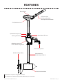 5
5
-
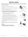 6
6
-
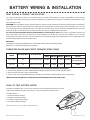 7
7
-
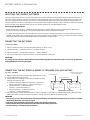 8
8
-
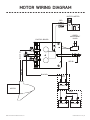 9
9
-
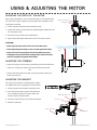 10
10
-
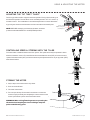 11
11
-
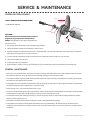 12
12
-
 13
13
-
 14
14
-
 15
15
-
 16
16
-
 17
17
-
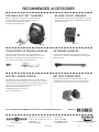 18
18
-
 19
19
-
 20
20
-
 21
21
-
 22
22
-
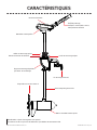 23
23
-
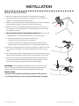 24
24
-
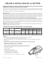 25
25
-
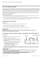 26
26
-
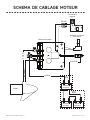 27
27
-
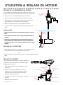 28
28
-
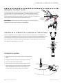 29
29
-
 30
30
-
 31
31
-
 32
32
-
 33
33
-
 34
34
-
 35
35
-
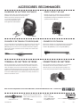 36
36
-
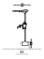 37
37
-
 38
38
-
 39
39
-
 40
40
-
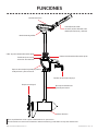 41
41
-
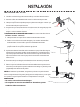 42
42
-
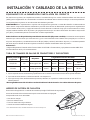 43
43
-
 44
44
-
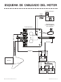 45
45
-
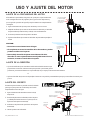 46
46
-
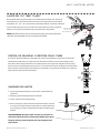 47
47
-
 48
48
-
 49
49
-
 50
50
-
 51
51
-
 52
52
-
 53
53
-
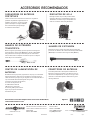 54
54
-
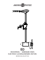 55
55
-
 56
56
-
 57
57
-
 58
58
-
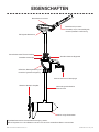 59
59
-
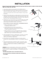 60
60
-
 61
61
-
 62
62
-
 63
63
-
 64
64
-
 65
65
-
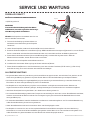 66
66
-
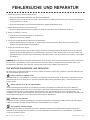 67
67
-
 68
68
-
 69
69
-
 70
70
-
 71
71
-
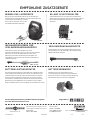 72
72


MINN KOTA MINN-KOTA 1363885 EO Transom Mount Electric Outboard Motor Manual de usuario
- Tipo
- Manual de usuario
en otros idiomas
Otros documentos
-
Sea Ray 1991 LAGUNA 23 OUTBOARD El manual del propietario
-
Mercury 15 Operation and Maintenance Manual
-
-
Yamaha 25V El manual del propietario
-
Greenworks 9000107 Manual de usuario
-
-
-
TOHATSU MFS 20C El manual del propietario
-
Simplicity 12Y602-0110-E6 Manual de usuario
-