La página se está cargando...

Instruction Manual
Manuale di istruzioni
Manuel d’instructions
Manual de instrucciones
Bedienungsanleitung
操作指南
AREX 5 Digital Heating Magnetic Stirrer
F20500580, F20510580
General Information / Informazioni Generali / Informations Générales / Información General / Allgemeine Hinweise / 基本信息
Before using the unit, please read the following instruction manual carefully.
Prima dell’utilizzo dello strumento si raccomanda di leggere attentamente il seguente manuale operativo.
Avant d’utiliser l’instrument, il est recommandé de lire attentivement le présent manuel d’instructions.
Antes de utilizar el instrumento, le recomendamos que lea con atención el siguiente manual de instrucciones.
Bitte lesen Sie vor Inbetriebnahme des Geräts diese Bedienungsanleitung sorgfältig durch.
使用前请仔细阅读以下使用说明书。
Caution, hot surface!
Attenzione, superficie calda!
Attention, surface chaude!
Prudencia, superficie caliente!
Vorsicht, heiße Oberfläche!
注意:加热面高温
Do not dispose of this equipment as urban waste, in accordance with EEC directive 2012/19/UE.
Non smaltire l’apparecchiatura come rifiuto urbano, secondo quanto previsto dalla Direttiva 2012/19/UE.
Ne pas recycler l’appareil comme déchet solide urbain, conformément à la Directive 2012/19/UE.
No tirar el equipo en los residuos urbanos, como exige la Directiva 2012/19/UE.
Dieses Gerät unterliegt der Richtlinie 2012/19/UE und darf nicht mit dem normalen Hausmüll entsorgt werden.
按照 EEC 指令 2002/96/CE,不要将该设备作为城市垃圾处理。
The product can be used with flammable liquids.
Il prodotto può essere utilizzato con liquidi infiammabili.
Le produit peut être utilisé avec des liquides inflammables.
El producto puede utilizarse con líquidos inflamables.
Das Produkt kann mit brennbaren Flüssigkeiten verwendet warden.
本产品可与易燃液体混合使用。

This unit must be used for indoor laboratory applications only.
The manufacturer declines all responsibility for any use of the unit that does not comply with these instructions. If the product is used in a
way not specified by the manufacturer or with non specified accessories, product's safety may be compromised.
Questo strumento deve essere utilizzato solo per applicazioni di laboratorio per uso interno.
La società produttrice declina ogni responsabilità sull’impiego non conforme alle istruzioni degli strumenti. Se il prodotto viene utilizzato in
un modo non specificato o con accessori non specificati dal costruttore stesso, la sicurezza del prodotto potrebbe essere compromessa.
Cet instrument ne peut être utilisé pour les applications de laboratoire à l'intérieur seulement.
Le fabriquant décline toute responsabilité en cas d’utilisation non conforme aux instructions concernant ces instruments. Si le produit est
utilisé d'une manière non spécifiée par le fabricant ou accessoires non spécifiés, la sécurité du produit peut être compromise.
Este dispositivo sólo debe utilizarse para aplicaciones de laboratorio para uso interno.
El fabricante declina toda responsabilidad por el uso no conforme a las instrucciones de los dispositivos. Si se utiliza el producto de una
manera no especificada o con accesorios no especificados de el fabricante, la seguridad del producto puede estar comprometida.
Dieses Gerät muss nur für Laboranwendungen verwendet werden.
Der Hersteller lehnt jede Haftung für unsachgemäße Verwendung oder Nichtbeachtung dieser Bedienungsanleitung ab. Wenn das
Produkt in einer Weise verwendet wird, die nicht vom Hersteller oder mit unsachgemäßer Zubehör angegeben, kann das Produkt die
Sicherheit beeinträchtigt werden.
这种装置只能在室内实验室使用。
制造商拒绝对任何不按照这些指示使用该装置的行为承担任何责任。如果产品是由制造商以未指定的方式使用或与未指定的配件一起使用,
产品的安全可能会受到危害。
This unit has been designed and manufactured in compliance with the following standards:
Lo strumento è stato progettato e costruito in accordo con le seguenti norme:
L’instrument a été conçu et fabriqué conformément aux normes suivantes:
El dispositivo se ha sido diseñado y fabricado de acuerdo con las siguientes normas:
Das Gerät wurde in Übereinstimmung mit folgenden Normen entwickelt und gebaut:
这种装置的设计和制造符合下列标准:
Safety requirements for electrical equipment for measurement, control and for laboratory use
Prescrizioni di sicurezza per apparecchi elettrici di misura, controllo e per l’utilizzo in laboratorio
Règles de sécurité pour appareils électriques de mesurage, de régulation et de laboratoire
Prescripciones de seguridad para equipos eléctricos de medición, control y su uso en laboratorio
Sicherheitsbestimmungen für elektrische Mess-, Steuer-, Regel- und Laborgeräte
测量,控制和实验室用电气设备的安全要求
IEC/EN 61010-1
IEC/EN 61010-2-051
IEC/EN 61010-2-010
Electrical equipment for laboratory use
UL 61010-1
General requirement - Canadian electrical code
CAN/CSA-C22.2 No.61010-1
VELP reserves the right to modify the characteristics of its products with the aim to constantly improve their quality.
Nell’impegno di migliorare costantemente la qualità dei prodotti, VELP si riserva la facoltà di variarne le caratteristiche.
Dans le but d’améliorer constamment la qualité de ses produits, VELP se réserve le droit d’apporter des modifications aux
caractéristiques de ceux-ci.
VELP se reserva el derecho de modificar las características de productos con el fin de mejorar constantemente su calidad.
VELP behält sich zum Zwecke der ständigen Verbesserung der Produktqualität das Recht auf Änderung der Geräteeigenschaften vor.
VELP 保留修改其产品特性的权利,以不断提高其质量。

Safety Regulations / Norme di Sicurezza / Consignes de Securité / Advertencias de Seguridad / Sicherheitshinweise / 安全法规
The plug disconnects the instrument. Therefore, place the instrument where it can be quickly disconnected.
La spina è il mezzo di disconnessione dell’apparecchio. Pertanto, non posizionare l’apparecchio in modo che sia difficile azionare il mezzo
di disconnessione.
Le bouchon est le moyen de déconnexion de l'appareil. Par conséquent, placer l'appareil où il peut être rapidement débranché.
El enchufe es el medio de desconexión del dispositivo. No coloque el dispositivo en una forma que es difícil de desconectar.
Der Stecker trennt das Gerät. Daher Stellen Sie das Instrument, wo es schnell getrennt werden kann.
仪器插头可插拔。请将仪器放置在可快速插拔电源的地方。
Use only the power cable provided with the instrument.
Utilizzare solo il cavo di alimentazione fornito con lo strumento.
Utilisez uniquement le câble d'alimentation fournis avec l’instrument.
Utilizar únicamente el cable de alimentación suministrado con el instrumento.
Verwenden Sie nur das mit dem Gerät gelieferte Stromkabel verwenden.
Hotplate temperature: up to 310 °C.
Temperatura piastra riscaldante: fino a 310 °C.
Température de la plaque chauffante: jusqu'à 310 °C.
Temperatura de la placa calefactora: hasta 310 °C.
Temperaturbereich Heizplatte: bis zu 310 °C.
加热板表面高温:达 310 °C。
The heated solution may release toxic, dangerous or poisonous gases. Adequate safety measures must be taken, in accordance with the
safety regulations in force, including the presence of hood and personal protective equipment (masks, gloves, goggles, etc.).
Le sostanze riscaldate potrebbero emanare gas tossici e/o pericolosi e/o velenosi. Adeguate misure di sicurezza devono essere prese, in
accordo con le normative di sicurezza dei prodotti in lavorazione e/o vigenti nei laboratori, compresa la presenza di cappe aspiranti e
mezzi di protezione individuale (maschere, guanti, occhiali, camici, ecc.).
La solution chauffée peut libérer gaz toxiques ou dangereux. Des mesures de sécurité adéquates doivent être prises, en conformité avec
les règlements de sécurité en vigueur, compris la présence de la hotte de laboratoire et équipements de protection individuelle (masques,
gants, lunettes, etc.).
Las sustancias calentadas pueden emitir tóxicos o peligrosos gas. Medidas de seguridad adecuadas deben ser adoptadas, de acuerdo
con las normas de seguridad vigentes en los laboratorios, incluyendo la presencia de la campana de humos y el equipo de protección
personal (mascarillas, guantes, gafas, etc.)
Die erwärmte Lösung kann giftige oder gefährliche Gase freigeben. Angemessene Sicherheitsmaßnahmen zu treffen, werden in
Übereinstimmung mit den geltenden Sicherheitsvorschriften, einschließlich der Anwesenheit Dunstabzug und persönliche
Schutzausrüstungen (Masken, Handschuhe, Schutzbrille, etc.).
加热后的溶液可能会释放出有毒、危险或有毒的气体。必须根据现行的安全规定,采取适当的安全措施,包括配备防护罩和个人防护装备(
面罩、手套、护目镜等)。
The vessel must be made of a suitable material to withstand the foreseen temperature.
Il contenitore del prodotto in lavorazione dovrà essere compatibile con la temperatura utilizzata.
Le contenant du produit en cours de traitement doit être compatible avec la température utilisée.
El recipiente debe estar hecho de un material adecuado para soportar la temperatura necearia.
Das Gefäß muss aus einem Material bestehen, das die vorgesehene Temperatur ausgelegt ist.
容器必须由适当的材料制成,以承受预期的温度。
Magnetic field doesn’t interfere with the function of cardiac pacemakers or data media if they are farther than 20 cm to the instrument.
Il campo magnetico non influisce su pacemaker o dispositivi di supporto dati se posti a più di 20 cm di distanza dalla piastra riscaldante.
Le champ magnétique n’affecte pas les stimulateurs cardiaques ou les dispositifs de support de données s’ils sont placés à plus de 20 cm
de la plaque chauffante.
El campo magnético no afecta a los marcapasos cardíacos ni a los dispositivos de soporte de datos cuando esos últimos se colocan a
más de 20 cm de distancia de la placa calefactora
Das Magnetfeld stört nicht die Funktion von Herzschrittmachern oder Datenträgern, wenn diese weiter als 20 cm vom Gerät entfernt sind.
如果心脏起搏器距离仪器超过20 厘米,磁场不会干扰其功能
Position the instrument on a flat surface, with a distance from the wall of 30 cm (at least).
Posizionare lo strumento su superfici piane, ad una distanza dalle pareti di almeno 30 cm.
Positionner l'appareil sur une surface plat, avec une distance de la paroi de 30 cm (au moins).
Coloque la unidad sobre una superficie plana, con una distancia de la pared de 30 cm (por lo menos).
Stellen Sie das Gerät auf einer ebenen Fläche mit einem Abstand zur Wand von 30 cm (mindestens).
将仪器放置在一个水平平台上,与墙壁的距离至少为 30 厘米。

Do not use with explosive or dangerous materials for which the equipment is not designed. The stirrer must not be used in explosive
atmospheres, in bain-marie or to stir combustible liquids that have a low combustion temperature. The product is intended for use with
very small quantities of flammable liquids or flammable liquids that have a fire point higher than 625°C and a flash point higher than
600°C.
Vietato l’uso con materiale esplosivo o pericoloso per cui l’apparecchio non è progettato. L’agitatore non può essere impiegato in
atmosfere esplosive, a bagnomaria e per agitare liquidi combustibili a bassa temperatura di combustione. Il prodotto è inteso per essere
usato con quantità molto limitate di liquidi infiammabili o con liquidi infiammabili con fire point maggiore di 625°C e flash point maggiore di
600°C.
Ne pas utiliser avec des matières explosives et dangereuses pour lesquelles l'équipement n'est pas conçu. L'agitateur ne peut pas être
utilisé dans des atmosphères explosives, dans un bain d'eau et pour remuer les combustibles liquides avec la température de combustion
bas. Le produit est destiné à être utilisé avec de très petites quantités de liquides inflammables ou de liquides inflammables ayant un point
d'incendie supérieur à 625°C et un point d'éclair supérieur à 600°C.
No debe utilizarse con materiales explosivos y peligrosos para los que el equipo no está diseñado. El agitador no puede ser utilizado en
ambientes explosivos, en baño de agua y para agitar combustibles con una baja temperatura de combustión. El producto está destinado
a ser utilizado con cantidades reducidas de líquidos inflamables o con líquidos inflamables que tengan un punto de ignición superior a
625 °C y con un punto de inflamación superior a 600°C.
Nicht mit explosivem Material zu verwenden, für die das Gerät nicht ausgelegt ist. Das Gerät kann nicht in explosionsgefährdeten
Bereichen eingesetzt werden, in einem Wasserbad und rühren für flüssige Brennstoffe mit niedrigen Verbrennungstemperatur. Das
Produkt ist für den Einsatz mit sehr geringen Mengen an brennbaren Flüssigkeiten oder brennbaren Flüssigkeiten mit einem Brandpunkt
von mehr als 625°C und einem Flammpunkt über 600°C vorgesehen.
不要与设备未设计的爆炸性或危险材料一起使用。搅拌器不得在爆炸性环境中使用,不得在蒸馏器中使用,也不得用于搅拌燃烧温度低的可
燃液体。本产品适用于极少量的易燃液体或火点高于 625℃、闪点高于 600℃的易燃液体。
It is responsibility of the user to appropriately decontaminate the instrument in case of dangerous substances fall on or in it accordingly to
the safety datasheet of substances used and to the current laboratories’ safety standards. It is not possible to decontaminate the product
under steam.
It is also responsibility of the user to use substances for cleaning or decontaminating which do not react with internal parts of the
instrument or with the material contained in it. In case of doubts about the compatibility of a cleaning solution, contact the manufacturer or
local distributor.
È responsabilità dell’utilizzatore un’appropriata decontaminazione in caso di versamento di sostanze pericolose sul o dentro l’apparecchio
in accordo con le schede di sicurezza delle sostanze utilizzate e agli standard di sicurezza in vigore nei laboratori. Non è possibile
decontaminare il prodotto con corrente di vapore.
È inoltre responsabilità dell’utilizzatore l’uso di sostanze decontaminanti o per la pulizia che non producano pericolo a causa di reazioni
con parti dell’apparecchio o con il materiale in esso contenuto. In caso di dubbio sulla compatibilità di un agente pulente o
decontaminante, contattare il produttore o un distributore locale.
Est responsabilité de l'utilisateur la décontamination en cas de déversement de matières dangereuses sur ou à l'intérieur de l'équipement
conformément à la fiche de données de sécurité des substances utilisées et aux normes de sécurité actuelles des laboratoires. Il n'est
pas possible de décontaminer le produit sous la vapeur.
Est responsabilité de l'utilisateur à utiliser des substances qui ne produisent pas de danger pour le nettoyage ou de décontamination, qui
ne réagissent pas avec les parties internes de l'appareil ou avec la matière qu'il contient. En cas de doute sur la compatibilité d'une
solution de nettoyage, contactez le fabricant ou le distributeur local.
Es responsabilidad del usuario una descontaminación adecuada en caso de derrame de sustancias peligrosas en o dentro el equipo
de acuerdo con las fichas de seguridad de las sustancias utilizadas y las normas de seguridad vigentes en los laboratorios. No es posible
descontaminar el producto con corriente de vapor.
Es responsabilidad del usuario también utilizar sustancias que no producen peligro para limpiar o descontaminar, que no reaccionan con
las partes internas del instrumento ni con el material contenido en él. En caso de duda sobre la compatibilidad de una solución de
limpieza, póngase en contacto con el fabricante o el distribuidor local.
Der Benutzer ist dafür verantwortlich, für die ordnungsgemäße Dekontamination beim Freiwerden gefährlicher Stoffe auf oder im Inneren
des Geräts entsprechend dem Sicherheitsdatenblatt der verwendeten Stoffe und Labors auf die aktuellen Sicherheitsstandards. Es ist
nicht möglich, das Produkt unter Dampf zu dekontaminieren.
Der Benutzer ist dafür verantwortlich, für die Reinigung oder Dekontaminierungsmitteln, die nicht mit internen Teile des Gerätes oder mit
dem Material in ihm enthaltenen reagieren. Im Zweifelsfall über die Vereinbarkeit einer Reinigungslösung den Hersteller, den Vertreiber
oder den Händler.
当危险物质落在仪器上或仪器内时,使用者有责任根据所使用物质的安全资料和现行实验室的安全标准,对仪器进行适当的清洁。禁止使用
蒸汽对本设备进行去污。
使用者亦有责任使用不会与仪器内部部件或仪器结构材料发生反应的物质进行清洁或去污。如果对清洁溶液的兼容性有疑问,请与制造商或
当地经销商联系。

Contents / Indice / Index / Índice / Inhalt / 目录
1. INTRODUCTION ................................................................................................................................................................................. 1
2. INSTALLATION................................................................................................................................................................................... 2
3. OPERATION ....................................................................................................................................................................................... 2
4. SETTING MODE ................................................................................................................................................................................. 4
5. ERROR AND WARNING MESSAGES ............................................................................................................................................... 5
6. MAINTENANCE .................................................................................................................................................................................. 5
7. TECHNICAL DATA ............................................................................................................................................................................. 5
1. INTRODUZIONE ................................................................................................................................................................................. 7
2. INSTALLAZIONE ................................................................................................................................................................................ 8
3. FUNZIONAMENTO ............................................................................................................................................................................. 8
4. MODALITA IMPOSTAZIONE PARAMETRI ...................................................................................................................................... 10
5. MESSAGGI DI ERRORE E ATTENZIONE ....................................................................................................................................... 11
6. MANUTENZIONE ............................................................................................................................................................................. 11
7. CARATTERISTICHE TECNICHE ..................................................................................................................................................... 11
1. INTRODUCTION ............................................................................................................................................................................... 13
2. INSTALLATION................................................................................................................................................................................. 14
3. OPERATION ..................................................................................................................................................................................... 14
4. MODE DE REGLAGE ....................................................................................................................................................................... 16
5. MESSAGES D’ERREUR ET D'AVERTISSEMENT .......................................................................................................................... 17
6. ENTRETIEN ...................................................................................................................................................................................... 17
7. DONNEES TECHNIQUES ................................................................................................................................................................ 17
1. INTRODUCCION .............................................................................................................................................................................. 19
2. INSTALACION .................................................................................................................................................................................. 20
3. OPERACION..................................................................................................................................................................................... 20
4. MODO DE AJUSTES ........................................................................................................................................................................ 22
5. MENSAJES DE ERROR Y ADVERTENCIA ..................................................................................................................................... 23
6. MANTENIMIENTO ............................................................................................................................................................................ 23
7. DATOS TECNICOS .......................................................................................................................................................................... 23
1. EINFÜHRUNG .................................................................................................................................................................................. 25
2. INSTALLATION................................................................................................................................................................................. 26
3. BETRIEB ........................................................................................................................................................................................... 26
4. EINSTELLUNGSMODUS ................................................................................................................................................................. 28
5. FEHLER- UND WARNMELDUNGEN ............................................................................................................................................... 29
6. WARTUNG........................................................................................................................................................................................ 29
7. TECHNISCHE DATEN ...................................................................................................................................................................... 29
1. 介绍 ................................................................................................................................................................................................... 31
2. 安装 ................................................................................................................................................................................................... 32
3. 运行 ................................................................................................................................................................................................... 32
4. 设置模式 ............................................................................................................................................................................................ 34
5. 错误和警告信息 ................................................................................................................................................................................. 35
6. 维护 ................................................................................................................................................................................................... 35
7. 技术数据 ............................................................................................................................................................................................ 36
8. ACCESSORIES / ACCESSORI / ACCESSOIRES / ACCESORIOS / ZUBEHÖR / 配件 .................................................................. 37
9. WIRING DIAGRAM / SCHEMA ELETTRICO / SCHÉMA ÉLECTRIQUE / ESQUEMA ELÉCTRICO / SCHALTPLAN / 线路图 ....... 39
10. DECLARATION OF CONFORMITY / DICHIARAZIONE DI CONFORMITA / DECLARATION DE CONFORMITE / DECLARACIÓN
DE CONFORMIDAD / KONFORMITÄTSERKLÄRUNG / 符合性声明 .................................................................................... 40
11. DECLARATION OF CONFORMITY ........................................................................................................................................... 41


1
1. Introduction
The AREX 5 Digital heating magnetic stirrer is used to heat and mix liquids inside a suitable container placed on the
aluminium plate. The stirring is possible thanks to a magnetic drive stir bar placed into the vessel.
The instrument is used in the laboratory for general use and for all those applications that require precise regulation of the
stirring speed and of the heating plate temperature.
The Aluminium alloy heating plate with ceramic coating (1) ensures:
• Optimum heat distribution and a high specific power thanks to the circular configuration
• Temperature homogeneity
• High resistance to thermal stress and thermal shock
• High resistance to chemical agents and surface abrasion
Note: Using the heating plate at high temperatures may cause discolouring. This does not alter the thermal, mechanical and
chemical resistance of the plate in any way.
The powerful brushless motor is able to stir from 50 up to 1500 rpm.
SpeedServo technology maintains constant speed as viscosity changes.
Note: it’s important to choose the most suitable magnetic stirring bar related to the type and the quantity of the liquid to be
stirred as well as to the type of the beaker. Size and shape of the magnetic stir bar determines the stirring efficiency at any
given speed. The stirring bar which satisfies most applications is code A00000356 (8 x 40 mm).
The AREX 5 Digital can work in combination with the Pt100 or Pt1000 external probe or with thermoregulator VTF for
precise and accurate control of the sample temperature.
1
Aluminum alloy plate with ceramic coating
A
Probe led
2
Main switch
B
Temperature setpoint led
3
Speed control knob
4
Temperature control knob
5
Display
EN
2
3
1
5
4

2
2. Installation
• Unpacking
➢ Check the integrity of the unit after unpacking
• The box includes
➢ AREX 5 Digital heating magnetic stirrer
➢ Instruction manual
➢ Power cable
• Installation
➢ Place the unit on a non-flammable surface
➢ Make sure that the technical specification of the unit and of the power supply line are the same
➢ Make sure that the electrical network is grounded
➢ Make sure that the main switch is on position “0” (OFF)
➢ Connect the instrument to an easily accessible socket (compliant with the current safety norms), using only the
provided power cable
Note: keep the power cable far away from the hot plate.
➢ Place the container with the liquid and the stir bar on the stirring plate
3. Operation
Power-up
• Turn the unit on using the main switch
• The display shows the software version and the last setpoint values
If the set starting mode is (see chap. 4), the heating and the stirring functions are not active and both displays
show . Otherwise, the unit starts working at the last set temperature and speed setpoints.
Stirring
• Rotate the right knob to set the stirring speed
• Push the knob to start stirring
• The real speed increases until set point achievement
• A microprocessor ensures constant speed even if the viscosity changes (SpeedServo)
• Push the knob to stop stirring
Heating
• Rotate the left knob to set the heating plate temperature
• Push the knob to start heating
• The display shows the current heating plate temperature for 3 seconds and the setpoint for 1 second
• When the display shows the temperature setpoint, the Set led is on
• Push the knob to stop heating
Note: if the heating function is not active and the heating plate temperature is higher than 50 °C, the display shows
the blinking message “Hot”. This warning is active even if the main switch is off but not if the instrument is not
powered.
Operation with thermoregulator VTF
• Turn off the instrument using the main switch
• Screw the threaded support rod into its seat on the back of the instrument and fasten the VTF thermoregulator onto
the support rod. Place the temperature probe in the flask making sure that it is completely immersed in the sample
• Plug the VTF into the dedicated socket on the back of the instrument
• Turn the unit on using the main switch. When the VTF is correctly connected, the Probe led is on. The working
temperature is shown on the display of the VTF
• Select the temperature set point on the VTF
• Push the left knob to start heating. The left display of the AREX 5 Digital shows ---

3
Note: The AREX 5 Digital always has primary control of the heating plate temperature. The temperature control
feature of the heating plate can also be used as a safety thermostat. In this case, the maximum temperature of the
heating plate will not exceed the temperature setting on the magnetic stirrer (see option chap. 4),
meaning that a longer heating time is required in order to reach the VTF thermoregulator temperature setting, thus
reducing temperature oscillation at a setpoint value.
Operation with external probe
• Turn off the instrument using the main switch
• Screw the threaded support rod into its seat on the back of the instrument (optional)
• Fasten the clamp onto the support rod (optional)
• Place the external temperature probe into the clamp (optional); then place it into the sample contained inside the
flask
• Plug the probe into the dedicated socket on the back of the instrument. The AREX 5 Digital automatically recognize
the type of temperature probe (Pt100 or Pt1000)
• Turn the unit on using the main switch. When the external probe is connected correctly, the Probe led is on
• Turn the left knob to set the working temperature; the Set led indicates that the display is showing the set point
temperature
• Push the left knob to start heating. The left display shows the temperature read by the probe for 3 seconds and the
setpoint for 1 second

4
4. Setting mode
Press both knobs for 3 seconds when heating and stirring are to access the setting mode.
Turn the left knob to browse through the available menus, listed below.
Press the right knob to see the set parameter. Then, turn the knob to modify the value of the parameter (when it is possible).
Press the knob to confirm.
To exit the setting mode, do not press/turn the knobs for 10 seconds or press both knobs at the same time.
Parameter shown
Default value
Range
Description
Display 1
Display 2
-
10 °C steps
Heating plate temperature limit
It limits the maximum value of the temperature setpoint for the
heating plate.
➢ If is selected, the heating function is “disabled”.
Starting mode
➢ : when the instrument is powered, the heating and the
stirring functions are not active and both displays show .
➢ : when the instrument is powered, it starts working at the
last temperature and speed setpoints.
Thermoregulation mode with external probe
➢ : optimized temperature control for minimized
overshoot and oscillations, slow rise in temperature.
➢ : fast rise in temperature, increased overshoot and
oscillations.
External probe safety alarm
➢ It allows enabling/disabling AL 6 and AL 7 error messages
(see chap. 5).
0,1 °C steps
Probe calibration
➢ It allows to align the external temperature probe reading to a
reference thermometer.
Stirring direction:
➢ : stirring direction is clockwise
➢ : stirring direction is counter clockwise
0,1 °C steps
Heating plate probe calibration
➢ It allows to align the heating plate probe reading to a
reference thermometer.
Motor and heating element operating time
It shows motor and heating element operating times.
Operating times are shown in hours up to 9999 hours (around
416 days). Then they are shown in days (a digits’ decimal point
is turned on).
Reset
➢ It allows to restore all system settings to their default values.

5
5. Error and warning messages
When the display shows an error message, the instrument functions automatically stop.
AL1
Heating plate overtemperature (T > 330 °C)
AL2
Excessive heating time
AL3
The stirring system doesn’t run correctly
AL4
External probe overtemperature
Only if the external probe is connected
AL5
Heating plate safety probe overtemperature (T > 370 °C)
AL6
Slow increase in temperature read by the external probe
Only if the external probe is connected
and is
AL7
Fast decrease in temperature read by the external probe
To remove the error message, restart the instrument from the main switch. For AL5 is necessary to disconnect the
instrument from the power supply.
If the alarm persists on the display, please contact VELP Scientifica’s technical assistance service.
6. Maintenance
No routine or extraordinary maintenance is required except periodic cleaning.
Cleaning
Disconnect the unit from the power supply and use a cloth dampened with a non-flammable non-aggressive detergent.
Repair
Repairs must be carried out by authorized Velp personnel only.
The transport of the instrument by freight forwarders, couriers or others must be carried out using the original shockproof
packaging. Follow any instructions on the original packaging (e.g., palletizing).
It is the responsibility of the user to properly decontaminate the unit in case of hazardous substances remaining on the
surface or interior of the device. If in doubt about the compatibility of a cleaning or decontamination product, contact the
manufacturer or distributor.
7. Technical data
General features
Model
F20500580
F20510580
Voltage
230 V – 50/60 Hz
115 V – 60 Hz
Power input
630 W
Current consumption
2,8 A
5,5 A
Dimensions (WxHxD)
160x85x270 mm (6,3x3,3x10,6 in)
Weight
1,7 kg (3,7 lb)
Construction material
Aluminium body – Technopolymer enclosure
Working in continuous
Admitted
Maximum load on the plate
25 kg (55 lb)
Noisiness
<< 80 dBa
Environmental temperature admitted
+5…+40 °C
Storage temperature admitted
-10…+60 °C
Level of electrical protection CEI EN60529
IP 42
Max humidity
80%
Overvoltage category
II
Pollution degree CEI EN61010-1
2
Max altitude
4000 m
Heating
Heating plate power output
600 W
Heating plate dimensions
Ø 135 mm
Temperature range
0 ÷ 310 °C (1 °C step)
Temperature resolution
1 °C
Heating plate construction material
CerAlTop™
Safety circuit
Separated with dedicated probe
Hot plate alarm
Over 50°C
Overtemperature alarm
Over 330°C

6
External probe
Type
Pt100 – Ø 3mm
or
Pt1000 – Ø 3mm (optional)
Temperature range
0 ÷ 310 °C (1 °C step)
Temperature resolution
1 °C
Accuracy
± 1 °C *
Electrical data
3.3 VDC – 1 W (max)
VTF
Temperature range
-10 ÷ 300 °C (1 °C step)
Temperature resolution
0,2 °C
Accuracy
+/-0,5°C*
Electrical data
12Vdc – 1.2W (max)
Stir
Stirring capacity
20 l H2O
Speed range
50 ÷ 1500 rpm (5 rpm step)
Speed resolution
1 rpm
Motor type
BLDC
Motor rating output
10 W
Counters
Motor
Operating hours
Heating plate
* in the following conditions: 800 ml of water in 1 liter glass beaker (diameter 105 mm), stirring bar 8 x 40 mm, 600 rpm,
50°C.

7
1. Introduzione
L’agitatore magnetico riscaldante AREX 5 Digital è utilizzato per riscaldare e mescolare liquidi all’interno di un contenitore
adeguato, posizionato sopra la piastra in alluminio. L’agitazione avviene mediante trascinamento magnetico di un’ancoretta
posta sul fondo del contenitore.
Lo strumento è adatto a tutte quelle applicazioni che richiedono una precisa regolazione della velocità di agitazione e della
temperatura della piastra riscaldante.
La piastra riscaldante (1), realizzata in alluminio con rivestimento in ceramica, conferisce:
• Ottimale distribuzione del calore con una elevata potenza specifica grazie alla configurazione circolare
• Ottima omogeneità di temperatura in tutti i punti della piastra
• Elevata resistenza a fatica termica e shock termici
• Elevata resistenza ad agenti chimici e abrasioni superficiali
Nota: l’utilizzo della piastra riscaldante ad alte temperature potrebbe determinare delle variazioni di colore superficiale che
non alterano le caratteristiche di resistenza termica, meccanica e chimica.
Il potente motore brushless consente di agitare ad una velocità regolabile da 50 a 1500 rpm.
La tecnologia SpeedServo permette di mantenere costante la velocità di agitazione anche a fronte di variazioni della
viscosità del campione.
Nota: è importante scegliere l’ancoretta magnetica più adeguata al tipo di liquido in agitazione e al tipo di becher utilizzato.
La dimensione e la forma dell’ancoretta magnetica influiscono sull’efficienza dell’agitazione. L’ancoretta che soddisfa la
maggior parte delle applicazioni è la A00000356 (8 x 40 mm).
L’AREX 5 Digital può funzionare in combinazione con la sonda esterna Pt100 o Pt1000 o con il termoregolatore VTF per
consentire una precisa ed accurata termoregolazione del campione.
1
Piastra riscaldante in alluminio con rivestimento ceramico
A
Led sonda
2
Interruttore generale
B
Led setpoint temperatura
3
Manopola per impostazione agitazione
4
Manopola per impostazione temperatura
5
Display
IT
A
B
2
3
1
5
4

8
2. Installazione
• Rimozione dall’imballo
➢ Controllare l’integrità dello strumento dopo averlo rimosso dall’imballo
• La scatola include
➢ AREX 5 Digital agitatore magnetico riscaldante
➢ Manuale di istruzioni
➢ Cavo di alimentazione
• Installazione
➢ Posizionare lo strumento su una superficie non infiammabile
➢ Verificare che i dati di targa dello strumento corrispondano a quelli disponibili alla presa di energia elettrica
➢ Assicurarsi che l’impianto elettrico sia dotato di impianto di messa a terra
➢ Assicurarsi che l’interruttore generale sia sulla posizione di “0” (OFF)
➢ Collegare lo strumento ad una presa facilmente accessibile (conforme alle norme di sicurezza), utilizzando
esclusivamente il cavo di alimentazione fornito.
Nota: tenere il cavo di alimentazione lontano dalla piastra riscaldante.
➢ Posizionare il contenitore con il liquido e l’ancoretta magnetica sulla superfice di appoggio dello strumento
3. Funzionamento
Accensione
• Accendere lo strumento mediante l’interruttore generale
• Il display mostra la versione software e gli ultimi valori di setpoint impostati
Se la modalità di funzionamento al riavvio è (vedi cap. 4), le funzioni di riscaldamento ed agitazione non sono
attive ed entrambi i display visualizzano . Altrimenti, lo strumento inizia a funzionare agli ultimi valori di setpoint
impostati.
Agitazione
• Ruotare la manopola di destra per impostare la velocità di agitazione
• Premere la manopola di destra per avviare l’agitazione
• La velocità reale aumenta fino al raggiungimento del setpoint
• Un microprocessore garantisce velocità di agitazione costante anche con variazioni della viscosità del liquido
(SpeedServo)
• Premere la manopola per fermare l’agitazione
Riscaldamento
• Ruotare la manopola di sinistra per impostare la temperatura di lavoro della piastra
• Premere la manopola per avviare il riscaldamento
• Il display mostra la temperatura corrente della piastra per 3 secondi e il valore di setpoint per 1 secondo
• Quando la temperatura di set point viene visualizzata, il led Set si accende
• Premere la manopola per interrompere il riscaldamento
Nota: se la funzione riscaldamento non è attiva e la temperatura della piastra è maggiore di 50 °C, il display mostra
la scritta “Hot” lampeggiante. Questa segnalazione è attiva anche se l’interruttore generale è spento, ma non è
attiva se lo strumento non è alimentato.
Funzionamento con termoregolatore VTF
• Spegnere lo strumento mediante l’interruttore generale
• Avvitare l’asta di sostegno filettata nell’apposita sede posta sul retro dello strumento e collocare su di essa il
termoregolatore VTF, controllando che la sonda di temperatura sia correttamente inserita nel campione in
lavorazione
• Inserire il connettore del termoregolatore VTF nella presa dedicata posta sul retro dello strumento
• Accendere lo strumento mediante l’interruttore generale. Quando il termoregolatore VTF è collegato correttamente,
il led Probe è acceso. La temperatura di lavoro è quella visualizzata sul display del termoregolatore VTF
• Selezionare il setpoint di temperatura sul termoregolatore VTF
• Premere la manopola di sinistra per iniziare il riscaldamento. Il display di sinistra dell’AREX 5 Digital visualizza ---

9
Nota: L’agitatore magnetico AREX 5 Digital esercita sempre il controllo primario della temperatura della piastra
riscaldante. Il controllo di temperatura della piastra riscaldante sull’agitatore magnetico può essere utilizzato anche
come termostato di sicurezza. In questo caso la piastra non supererà la temperatura impostata sull’agitatore
magnetico (vedi opzione cap. 4), implicando un tempo più lungo per il raggiungimento della temperatura
selezionata sul termoregolatore VTF, ma riducendo così le oscillazioni di temperatura intorno al setpoint.
Funzionamento con sonda esterna
• Spegnere lo strumento mediante l’interruttore generale.
• Avvitare l’asta di sostegno filettata nell’apposita sede posta sul retro dello strumento (facoltativo).
• Fissare il morsetto di supporto sull’asta (facoltativo).
• Collocare la sonda esterna nel morsetto (facoltativo); dopodiché, posizionarla all’interno del campione contenuto in
un apposito contenitore.
• Inserire il connettore della sonda nella presa dedicata posta sul retro dello strumento. L’AREX 5 Digital riconosce
automaticamente il tipo di sonda inserita (Pt100 o Pt1000).
• Accendere lo strumento mediante l’interruttore generale. Quando la sonda di temperatura è collegata
correttamente, il led Probe è acceso
• Ruotare la manopola di sinistra per impostare la temperatura di lavoro; l’accensione del led Set indica che il display
sta visualizzando la temperatura di setpoint.
• Premere la manopola di sinistra per iniziare il riscaldamento. Il display di sinistra mostra la temperatura corrente
letta dalla sonda per 3 secondi ed il valore di setpoint per 1 secondo.

10
4. Modalità impostazione parametri
Premere entrambe le manopole per 3 secondi quando riscaldamento e agitazione non sono attivi per accedere alla modalità
impostazione parametri.
Ruotare la manopola di sinistra per scorrere tra i menù disponibili, elencati in seguito.
Premere la manopola di destra per vedere il parametro impostato. Dopodiché, ruotare la manopola per modificare il valore
del parametro (quando possibile). Premere la manopola per confermare.
Per uscire dalla programmazione parametri attendere 10 secondi senza interagire con lo strumento, oppure premere
entrambe le manopole contemporaneamente.
Testo visualizzato
Valore di default
Range
Nome del menù e descrizione
Display 1
Display 2
–
Step da 10 °C
Fondo-scala temperatura piastra
Permette di limitare il massimo valore di setpoint temperatura
piastra impostabile.
Selezionando , la funzione riscaldamento viene “disabilitata”.
Modalità di funzionamento al riavvio
➢ : all’accensione dello strumento, le funzioni
riscaldamento e agitazione non sono attive ed entrambi i
display visualizzano
➢ : all’accensione dello strumento, questo inizia a
funzionare agli ultimi valori di setpoint impostati
Modalità termoregolazione con sonda esterna
➢ : regolazione temperatura ottimizzata, overshoot e
oscillazioni minimizzati, lento incremento della temperatura
➢ : veloce aumento della temperatura, overshoot e
oscillazioni maggiori
Allarmi sonda esterna
Permette di abilitare / disabilitare gli allarmi AL 6 e AL 7 (vedi
cap. 5).
Step da 0,1 °C
Calibrazione sonda esterna
Permette l’allineamento della lettura della sonda di temperatura
esterna con un termometro di riferimento.
Scelta del senso di rotazione
➢ : l’agitazione è in senso orario
➢ : l’agitazione è in senso antiorario
Step da 0,1 °C
Calibrazione sonda della piastra riscaldante
Permette l’allineamento della lettura della sonda di temperatura
della piastra riscaldante con un termometro di riferimento.
Tempo di funzionamento motore ed elemento riscaldante
Visualizza i tempi di funzionamento di motore ed elemento
riscaldante.
I tempi di lavoro sono visualizzati in ore fino a 9999 ore (circa
416 giorni). Dopodiché, vengono visualizzati in giorni (il punto
decimale di un digit del display viene acceso).
Reset
➢ Permette di ripristinare tutti i parametri di sistema ai valori di
default.

11
5. Messaggi di errore e attenzione
Quando il display mostra un messaggio di allarme, in automatico le funzioni dello strumento vengono bloccate.
AL1
Sovratemperatura della piastra riscaldante (T > 330°C)
AL2
Tempo di riscaldamento eccessivo
AL3
Anomalia del sistema di agitazione
AL4
Sovratemperatura della sonda esterna
Solo se la sonda esterna è connessa
AL5
Sovratemperatura della sonda di sicurezza (T > 370°C)
AL6
Lento incremento di temperatura letto dalla sonda esterna
Solo se la sonda esterna è connessa e
se è
AL7
Rapida diminuzione di temperature letta dalla sonda esterna
Per rimuovere gli allarmi è necessario riavviare lo strumento tramite l’interruttore generale. Per AL5 è necessario scollegare
lo strumento dalla rete di alimentazione.
Se l’allarme persiste sul display, contattare il servizio di assistenza tecnica di VELP Scientifica.
6. Manutenzione
La manutenzione ordinaria e straordinaria non è prevista salvo la pulizia periodica.
Pulizia
Scollegare lo strumento dall’alimentazione e pulire con un panno inumidito con detergenti non infiammabili e non aggressivi.
Riparazione
Eventuali riparazioni dovranno essere eseguite soltanto da parte di personale autorizzato Velp.
Il trasporto dello strumento tramite spedizionieri, corrieri o altro, deve essere effettuato utilizzando l'imballo originale antiurto
di cui lo strumento è dotato quando spedito da nuovo. Seguire le istruzioni eventualmente riportate sullo stesso (es.
pallettizzare).
È responsabilità dell'utente procedere alla decontaminazione dell'unità nel caso in cui sostanze pericolose rimangano sulla
superficie o all'interno del dispositivo. In caso di dubbi sulla compatibilità di un prodotto per la pulizia o la decontaminazione,
contattare il produttore o il distributore.
7. Caratteristiche tecniche
Caratteristiche generali
Modelli
F20500580
F20510580
Alimentazione
230 V – 50/60 Hz
115 V – 60 Hz
Potenza assorbita
630 W
Corrente assorbita
2,8 A
5,5 A
Dimensioni (LxLxH)
160x85x270 mm (6,3x3,3x10,6 in)
Peso
1,7 kg (3,7 lb)
Materiale di costruzione
Corpo in alluminio – Fondo in tecnopolimero
Funzionamento in continuo
Ammesso
Massimo carico sulla piastra
25 kg
Rumorosità
<< 80 dBa
Temperatura ambiente ammessa
+5…+40 °C
Temperatura di stoccaggio ammessa
-10…+60 °C
Umidità max ammessa
80%
Grado di protezione elettrica CEI EN60529
IP 42
Categoria di sovratensione
II
Grado di inquinamento CEI EN61010-1
2
Altitudine massima
4000 m
Riscaldamento
Potenza della piastra riscaldante
600 W
Dimensioni della piastra riscaldante
Ø 135 mm
Ambito temperatura impostabile
0 ÷ 310 °C (step da 1 °C)
Risoluzione lettura temperatura
1 °C
Materiale di costruzione della piastra
CerAlTop™
Circuito di sicurezza
Separato con sonda dedicata
Allarme piastra calda
Sopra 50°C
Allarme sovratemperatura
Sopra 330°C

12
Sonda esterna
Tipo
Pt100 – Ø 3mm
o
Pt1000 – Ø 3mm (opzionale)
Ambito temperatura impostabile
0 ÷ 310 °C (step da 1 °C)
Risoluzione lettura temperatura
1 °C
Accuratezza
± 1 °C *
Dati elettrici
3.3 VDC – 1 W (max)
VTF
Temperature range
-10 ÷ 300 °C (step da 1 °C)
Temperature resolution
0,2 °C
Accuratezza
+/-0,5°C*
Dati elettrici
12Vdc – 1.2W (max)
Agitazione
Capacità di agitazione
20 l H2O
Ambito velocità impostabile
50 ÷ 1500 rpm (step da 5 rpm)
Risoluzione lettura velocità
1 rpm
Tipo di motore
BLDC
Potenza motore
10 W
Contatori
Motore
Ore di funzionamento
Piastra riscaldante
* nelle seguenti condizioni: 800 ml di acqua in becher di vetro da 1 litro (diametro 105 mm), ancoretta 8 x 40 mm, 600 rpm,
50 °C.

13
1. Introduction
L'agitateur magnétique chauffant AREX 5 Digital permet de chauffer et de mélanger des liquides dans un récipient adapté et
posé sur le plateau en aluminium. L'agitation est possible grâce à un barreau d'agitation à entraînement magnétique placé
dans le recipient.
L'instrument est utilisé en laboratoire pour un usage général et pour toutes les applications qui nécessitent une régulation
précise de la vitesse d'agitation et de la température de la plaque chauffante.
La plaque chauffante en alliage d'Aluminium avec revêtement céramique (1) assure :
• Répartition optimale de la chaleur et puissance spécifique élevée grâce à la configuration circulaire
• Homogénéité de la température
• Haute résistance aux contraintes thermiques et aux chocs thermiques
• Haute résistance aux agents chimiques et à l'abrasion de surface
Remarque: L'utilisation de la plaque chauffante à des températures élevées peut entraîner une décoloration. Cela n'altère
en rien la résistance thermique, mécanique et chimique de la plaque.
Le puissant moteur sans balais est capable d'agiter de 50 à 1500 rpm.
La technologie SpeedServo maintient une vitesse constante lorsque la viscosité change .
Remarque : il est important de choisir le barreau magnétique le plus adapté au type et à la quantité de liquide à agiter ainsi
qu'au type de bécher. La taille et la forme de la barre d'agitation magnétique déterminent l'efficacité de l'agitation à une
vitesse donnée. Le barreau d'agitation qui satisfait la plupart des applications est le code A00000356 (8 x 40 mm).
L'AREX 5 Digital peut fonctionner en combinaison avec la sonde externe Pt100 ou Pt1000 ou avec le thermorégulateur VTF
pour un contrôle précis et précis de la température de l'échantillon.
1
Plaque en alliage d'aluminium avec revêtement en céramique
A
Sonde led
2
Interrupteur principal
B
Voyant de consigne de température
3
Bouton de contrôle de la vitesse
4
Bouton de contrôle de la température
5
Ecran
FR
2
3
1
5
4
B
A

14
2. Installation
• Déballage
➢ Vérifier l'intégrité de l'appareil après le déballage
• L‘emballage comprend
➢ Agitateur magnétique chauffant numérique AREX 5
➢ Manuel d'instructions
➢ Câble d'alimentation
• Installation
➢ Placer l'appareil sur une surface ininflammable
➢ Assurez-vous que les caractéristiques techniques de l'unité et de la ligne d'alimentation sont les mêmes
➢ Assurez-vous que le réseau électrique est mis à la terre
➢ Assurez-vous que l'interrupteur principal est sur la position "0" (OFF)
➢ Connectez l'instrument à une prise facilement accessible (conforme aux normes de sécurité en vigueur), en
utilisant uniquement le câble d'alimentation fourni
Remarque : éloignez le câble d'alimentation de la plaque chauffante.
➢ Placer le récipient avec le liquide et la barre d'agitation sur la plaque d'agitation
3. Opération
Mise sous tension
• Allumez l'appareil à l'aide de l'interrupteur principal
• L'écran affiche la version du logiciel et les dernières valeurs de consigne
Si le mode de démarrage réglé est (voir chap. 4), les fonctions de chauffage et d'agitation ne sont pas actives
et les deux affichages indiquent . Sinon, l'unité commence à fonctionner aux dernières consignes de
température et de vitesse réglées.
Agitation
• Tournez le bouton droit pour régler la vitesse d'agitation
• Appuyez sur le bouton pour commencer à remuer
• La vitesse réelle augmente jusqu'à l'atteinte de la consigne
• Un microprocesseur assure une vitesse constante même si la viscosité change (SpeedServo)
• Appuyez sur le bouton pour arrêter de remuer
Chauffage
• Tournez le bouton gauche pour régler la température de la plaque chauffante
• Appuyez sur le bouton pour démarrer le chauffage
• L'écran affiche la température actuelle de la plaque chauffante pendant 3 secondes et la consigne pendant 1
seconde
• Lorsque l'écran affiche la température de consigne, la led Set est allumée
• Appuyez sur le bouton pour arrêter le chauffage
Remarque : si la fonction de chauffage n'est pas active et que la température de la plaque chauffante est
supérieure à 50 °C, l'écran affiche le message clignotant « Hot ». Cet avertissement est actif même si l'interrupteur
principal est éteint mais pas si l'instrument n'est pas alimenté.
Fonctionnement avec thermorégulateur VTF
• Éteignez l'instrument à l'aide de l'interrupteur principal
• Visser la tige de support filetée dans son logement au dos de l'instrument et fixer le thermorégulateur VTF sur la
tige de support. Placer la sonde de température dans le flacon en s'assurant qu'elle est complètement immergée
dans l'échantillon
• Branchez le VTF dans la prise dédiée à l'arrière de l'instrument
• Allumez l'appareil à l'aide de l'interrupteur principal. Lorsque le VTF est correctement connecté, la led Probe est
allumée. La température de travail est indiquée sur l'écran du VTF
• Sélectionner la consigne de température sur le VTF
• Appuyez sur le bouton de gauche pour démarrer le chauffage. L'écran de gauche de l'AREX 5 Digital affiche ---

15
Remarque : L'AREX 5 Digital a toujours le contrôle principal de la température de la plaque chauffante. La fonction
de contrôle de la température de la plaque chauffante peut également être utilisée comme thermostat de sécurité.
Dans ce cas, la température maximale du plateau chauffant ne dépassera pas la température de consigne de
l'agitateur magnétique (voir option type. 4), ce qui signifie qu'un temps de chauffage plus long est
nécessaire pour atteindre la consigne de température du thermorégulateur VTF, réduisant ainsi l'oscillation de
température à une valeur de consigne.
Fonctionnement avec sonde externe
• Éteignez l'instrument à l'aide de l'interrupteur principal
• Visser la tige de support filetée dans son siège à l'arrière de l'instrument (optionnel)
• Fixer la pince sur la tige de support (facultatif)
• Placer la sonde de température externe dans la pince (optionnel) ; puis placez-le dans l'échantillon contenu à
l'intérieur du flacon
• Branchez la sonde dans la prise dédiée à l'arrière de l'instrument. L'AREX 5 Digital reconnaît automatiquement
le type de sonde de température (Pt100 ou Pt1000)
• Allumez l'appareil à l'aide de l'interrupteur principal. Lorsque la sonde externe est correctement connectée, le
voyant Sonde est allumé
• Tournez le bouton de gauche pour régler la température de travail ; la led Set indique que l'écran affiche la
température de consigne
• Appuyez sur le bouton de gauche pour démarrer le chauffage . L'afficheur de gauche affiche la température lue
par la sonde pendant 3 secondes et la consigne pendant 1 seconde

16
4. Mode de réglage
Appuyez sur les deux boutons pendant 3 secondes lorsque le chauffage et l'agitation sont éteints pour accéder au mode de
réglage.
Tourner le bouton de gauche pour parcourir les menus disponibles, listés ci-dessous.
Appuyez sur le bouton droit pour voir le paramètre défini. Ensuite, tournez le bouton pour modifier la valeur du paramètre
(lorsque c'est possible). Appuyez sur le bouton pour confirmer.
Pour quitter le mode réglage, appuyer/tourner les boutons pendant 10 secondes ou appuyer sur les deux boutons en même
temps.
Paramètre affiché
Valeur par défaut
Gamme
Description
Affichage
1
Affichage
2
-
10 °C steps
Limite de température de la plaque chauffante
Il limite la valeur maximale de la consigne de température du
plateau chauffant.
➢ Si est sélectionné, la fonction de chauffage est «
désactivée ».
Mode de démarrage
➢ : lorsque l'instrument est sous tension, les fonctions
de chauffage et d'agitation ne sont pas actives et les deux
affichages indiquent .
➢ : lorsque l'instrument est alimenté, il commence à
fonctionner aux dernières consignes de température et de
vitesse.
Mode thermorégulation avec sonde externe
➢ : contrôle optimisé de la température pour minimiser
les dépassements et les oscillations, montée en température
lente.
➢ : montée en température rapide, dépassement et
oscillations accrus.
Alarme de sécurité sonde externe
➢ Il permet d'activer/désactiver les messages d'erreur AL 6 et
AL 7 (voir chap. 5).
0,1 °C steps
Étalonnage de la sonde
➢ Il permet d'aligner la lecture de la sonde de température
externe sur un thermomètre de référence.
Sens d'agitation :
➢ : le sens d'agitation est dans le sens des aiguilles d'une
montre
➢ : le sens d'agitation est dans le sens inverse des aiguilles
d'une montre
0,1 °C steps
Étalonnage de la sonde de la plaque chauffante
➢ Il permet d'aligner la lecture de la sonde de la plaque
chauffante sur un thermomètre de référence.
Réinitialiser
➢ Il permet de restaurer tous les paramètres du système à
leurs valeurs par défaut.

17
5. Messages d’erreur et d'avertissement
Lorsque l'écran affiche un message d'erreur, les fonctions de l'instrument s'arrêtent automatiquement.
AL1
Surchauffe plaque chauffante (T > 330 °C)
AL2
Temps de chauffe excessif
AL3
Le système d'agitation ne fonctionne pas correctement
AL4
Surchauffe sonde externe
Uniquement si la sonde externe est
connectée
AL5
Surchauffe sonde de sécurité plaque chauffante (T > 370 °C)
AL6
Augmentation lente de la température lue par la sonde externe
Uniquement si la sonde externe est
connectée et est
AL7
Baisse rapide de la température lue par la sonde externe
Pour supprimer le message d'erreur, redémarrez l'instrument à partir de l'interrupteur principal. Pour AL5, il est nécessaire
de débrancher l'instrument de l'alimentation électrique.
Si l'alarme persiste à l'écran, veuillez contacter le service d'assistance technique de VELP Scientifica.
6. Entretien
Aucun entretien de routine ou extraordinaire n'est requis, à l'exception d'un nettoyage périodique.
Nettoyage
Débranchez l'appareil de l'alimentation électrique et utilisez un chiffon imbibé d'un détergent ininflammable et non agressif.
Réparation
Les réparations doivent être effectuées uniquement par du personnel Velp agréé.
Le transport de l'instrument par des transitaires, des transporteurs ou autres, doit être effectué en utilisant l'original antichoc
emballage. Suivez toutes les instructions sur l'emballage d'origine (par exemple, la palettisation).
Il est de la responsabilité de l'utilisateur de décontaminer correctement l'appareil en cas de substances dangereuses restant
à la surface ou à l'intérieur de l'appareil. En cas de doute sur la compatibilité d'un produit de nettoyage ou de
décontamination, contactez le fabricant ou le distributeur.
7. Données techniques
Caractéristiques générales
Modèle
F20500580
F20510580
Tension
230 V – 50/60 Hz
115 V – 60 Hz
Entrée de puissance
630W
Consommation de courant
2,8 A
5,5 A
Dimensions (LxHxP)
160x85x270 mm (6,3x3,3x10,6 in)
Lester
1,7 kg (3,7 lb)
Materiel de construction
Corps en aluminium – Boîtier en technopolymère
Travailler en continu
Admis
Charge maximale sur la plaque
25 kg (55 lb)
Caractère bruyant
<< 80dBa
Température ambiante admise
+5…+40 °C
Température de stockage admise
-10…+60 °C
Niveau de protection électrique CEI EN60529
IP 42
Humidité maximale
80%
Catégorie de surtension
II
Degré de pollution CEI EN61010-1
2
Altitude maximale
4000 mètres
Chauffage
Puissance de sortie de la plaque chauffante
600W
Dimensions plaque chauffante
Ø 135 mm
Écart de température
0 ÷ 310 °C (pas de 1 °C)
Résolution de température
1 °C
Matériau de construction de la plaque chauffante
CerAlTop™
Circuit de sécurité
Séparé avec sonde dédiée
Alarme plaque chauffante
Plus de 50°C
Alarme de surchauffe
Plus de 330°C

18
Sonde externe
Taper
Pt100 – Ø 3mm
ou
Pt1000 – Ø 3mm (en option)
Écart de température
0 ÷ 310 °C (pas de 1 °C)
Résolution de température
1 °C
Précision
± 1 °C *
Données électriques
3,3 VCC – 1 W (max)
VTF
Écart de température
-10 ÷ 300 °C (pas de 1 °C)
Résolution de température
0,2 °C
Précision
+/-0,5°C*
Données électriques
12Vdc – 1.2W (max)
Remuer
Capacité d'agitation
20 l H2O
Plage de vitesse
50 ÷ 1500 rpm (pas de 5 rpm)
Résolution de vitesse
1 rpm
Type de moteur
BLDC
Puissance nominale du moteur
10W
Compteurs
Moteur
Heures d'ouverture
Plaque chauffante
* dans les conditions suivantes : 800 ml d'eau dans un bécher en verre de 1 litre (diamètre 105 mm), barreau d'agitation 8 x
40 mm, 600 rpm, 50°C.

19
1. Introducción
El agitador magnético con calefacción digital AREX 5 se utiliza para calentar y mezclar líquidos dentro de un recipiente
adecuado colocado en la placa de aluminio. La agitación es posible gracias a una barra de agitación de accionamiento
magnético colocada en el recipiente.
El instrumento se utiliza en el laboratorio para uso general y para todas aquellas aplicaciones que requieren una regulación
precisa de la velocidad de agitación y de la temperatura de la placa de calentamiento.
La placa calefactora de aleación de aluminio con revestimiento cerámico (1) garantiza:
• Óptima distribución del calor y alta potencia específica gracias a la configuración circular.
• Homogeneidad de temperature.
• Alta resistencia al estrés térmico y al choque térmico.
• Alta resistencia a los agentes químicos y a la abrasión superficial.
Nota: El uso de la placa calefactora a altas temperaturas puede causar decoloración. Esto no altera en modo alguno la
resistencia térmica, mecánica y química de la placa.
El potente motor sin escobillas puede agitar desde 50 hasta 1500 rpm.
La tecnología SpeedServo mantiene una velocidad constante a medida que cambia la viscosidad .
Nota: es importante elegir la barra de agitación magnética más adecuada en relación con el tipo y la cantidad de líquido a
agitar, así como con el tipo de vaso de precipitados. El tamaño y la forma de la barra de agitación magnética determina la
eficiencia de agitación a cualquier velocidad dada. La barra agitadora que satisface la mayoría de las aplicaciones es el
código A00000356 (8 x 40 mm).
El AREX 5 Digital puede funcionar en combinación con la sonda externa Pt100 o Pt1000 o con el termorregulador VTF para
un control preciso y exacto de la temperatura de la muestra.
1
Placa de aleación de aluminio con revestimiento
cerámico
A
Led de sonda
2
Interruptor principal
B
Led de consigna de temperatura
3
Perilla de control de velocidad
4
Perilla de control de temperatura
5
Pantalla
ES
2
3
1
5
4

20
2. Instalación
• Desembalaje
➢ Compruebe la integridad de la unidad después de desembalar.
• La caja incluye
➢ Agitador magnético con calefacción digital AREX 5.
➢ Manual de instrucciones.
➢ Cable de energía.
• Instalación
➢ Coloque la unidad sobre una superficie no inflamable.
➢ Asegúrese de que las especificaciones técnicas de la unidad y de la línea de alimentación sean las mismas.
➢ Asegúrese de que la red eléctrica esté conectada a tierra.
➢ Asegúrese de que el interruptor principal esté en la posición "0" (APAGADO).
➢ Conecte el instrumento a un enchufe de fácil acceso (que cumpla con las normas de seguridad vigentes),
utilizando únicamente el cable de alimentación suministrado.
Nota: mantenga el cable de alimentación alejado de la placa caliente.
➢ Coloque el recipiente con el líquido y la barra de agitación en la placa de agitación.
3. Operación
Encendido
• Encienda la unidad con el interruptor principal.
• La pantalla muestra la versión del software y los últimos valores de consigna.
Si el modo de inicio configurado es (ver cap. 4), las funciones de calentamiento y agitación no están activas y
ambas pantallas muestran . De lo contrario, la unidad comienza a funcionar con los últimos puntos de ajuste de
temperatura y velocidad establecidos.
Agitación
• Gire la perilla derecha para establecer la velocidad de agitación.
• Presione la perilla para comenzar a agitar.
• La velocidad real aumenta hasta alcanzar el valor de consigna.
• Un microprocesador asegura una velocidad constante incluso si cambia la viscosidad (SpeedServo).
• Presione la perilla para dejar de agitar.
Calefacción
• Gire la perilla izquierda para configurar la temperatura de la placa de calentamiento.
• Presione la perilla para comenzar a calentar.
• La pantalla muestra la temperatura actual de la placa de calentamiento durante 3 segundos y el punto de referencia
durante 1 segundo.
• Cuando la pantalla muestra el punto de ajuste de temperatura, el led Set estará encendido.
• Presione la perilla para detener el calentamiento.
Nota: si la función de calentamiento no está activa y la temperatura de la placa de calentamiento es superior a 50
°C, la pantalla muestra el mensaje intermitente "Hot". Esta advertencia está activa incluso si el interruptor principal
está apagado, pero no si el instrumento no está alimentado.
Funcionamiento con termorregulador VTF
• Apague el instrumento usando el interruptor principal.
• Atornille la varilla de soporte roscada en su asiento en la parte posterior del instrumento y fije el termorregulador
VTF en la varilla de soporte. Coloque la sonda de temperatura en el matraz asegurándose de que esté
completamente sumergida en la muestra.
• Conecte el VTF en el enchufe dedicado en la parte posterior del instrumento.
• Encienda la unidad usando el interruptor principal. Cuando el VTF está correctamente conectado, el led de la sonda
está encendido. La temperatura de trabajo se muestra en la pantalla del VTF.
• Seleccione el punto de ajuste de temperatura en el VTF.
• Presione la perilla izquierda para comenzar a calentar. La pantalla izquierda del AREX 5 Digital muestra ---.

21
Nota: el AREX 5 Digital siempre tiene el control principal de la temperatura de la placa de calentamiento. La
función de control de temperatura de la placa calefactora también se puede utilizar como termostato de seguridad.
En este caso, la temperatura máxima de la placa calefactora no superará la temperatura configurada en el
agitador magnético (ver opción cap. 4), lo que significa que se requiere un mayor tiempo de
calentamiento para alcanzar el ajuste de temperatura del termorregulador VTF, lo que reduce la oscilación de
temperatura en un valor de punto de ajuste.
Funcionamiento con sonda externa
• Apague el instrumento usando el interruptor principal.
• Atornille la varilla de soporte roscada en su asiento en la parte posterior del instrumento (opcional).
• Fije la abrazadera en la barra de soporte (opcional).
• Coloque la sonda de temperatura externa en la abrazadera (opcional); luego colóquela en la muestra contenida
dentro del matraz.
• Conecte la sonda en el enchufe dedicado en la parte posterior del instrumento. El AREX 5 Digital reconoce
automáticamente el tipo de sonda de temperatura (Pt100 ó Pt1000).
• Encienda la unidad usando el interruptor principal. Cuando la sonda externa está conectada correctamente, el led
Probe estará encendido.
• Gire la perilla izquierda para configurar la temperatura de trabajo; el led Set indica que la pantalla está mostrando
la temperatura del punto de ajuste.
• Presione la perilla izquierda para comenzar a calentar. La pantalla izquierda muestra la temperatura leída por la
sonda durante 3 segundos y el punto de ajuste durante 1 segundo.

22
4. Modo de ajustes
Presione ambas perillas durante 3 segundos cuando el calentamiento y la agitación estén apagados para acceder al modo
de configuración.
Gire la perilla izquierda para navegar a través de los menús disponibles, que se enumeran a continuación.
Presione la perilla derecha para ver el parámetro establecido. Luego, gire la perilla para modificar el valor del parámetro
(cuando sea posible). Presione la perilla para confirmar.
Para salir del modo de configuración, no presione/gire las perillas durante 10 segundos o presione ambas perillas al mismo
tiempo.
Parámetro mostrado
Valor por defecto
Rango
Descripción
Pantalla 1
Pantalla
1
Pantalla
2
-
10 °C steps
Límite de temperatura de la placa de calentamiento
Limita el valor máximo de consigna de temperatura de la placa
calefactora.
➢ Si se selecciona , la función de calentamiento estará
“deshabilitada”.
Modo de inicio
➢ : cuando el instrumento está alimentado, las funciones
de calentamiento y agitación no están activas y ambas
pantallas muestran .
➢ : cuando el instrumento está alimentado, comienza a
funcionar en los últimos puntos de ajuste de temperatura y
velocidad.
Modo de termorregulación con sonda externa
➢ : control de temperatura optimizado para minimizar
las oscilaciones y los excesos, aumento lento de la
temperatura.
➢ : aumento rápido de la temperatura, sobreimpulso y
oscilaciones aumentados.
Alarma de seguridad de sonda externa
➢ Permite habilitar/deshabilitar los mensajes de error AL 6 y
AL 7 (ver cap. 5).
Pasos de 0,1 °C
Calibración de sonda
➢ Permite alinear la lectura de la sonda de temperatura
externa a un termómetro de referencia.
Dirección de agitación:
➢ : la dirección de agitación es en el sentido de las agujas
del reloj.
➢ : la dirección de agitación es en el sentido inverso de las
agujas del reloj.
Pasos de 0,1 °C
Calibración de la sonda de la placa de calentamiento
➢ Permite alinear la lectura de la sonda de la placa calefactora
con un termómetro de referencia.
Tiempo de funcionamiento del motor y del elemento calefactor
Muestra los tiempos de funcionamiento del motor y del elemento
calefactor.
Los tiempos de funcionamiento se muestran en horas hasta
9999 horas (alrededor de 416 días). Luego se muestran en días
(se activa el punto decimal de un dígito).
Reiniciar
➢ Permite restaurar todas las configuraciones del sistema a
sus valores predeterminados.

23
5. Mensajes de error y advertencia
Cuando la pantalla muestra un mensaje de error, las funciones del instrumento se detienen automáticamente.
AL1
Sobretemperatura de la placa de calentamiento (T > 330 °C)
AL2
Tiempo de calentamiento excesivo
AL3
El sistema de agitación no funciona correctamente
AL4
Sobretemperatura sonda externa
Sólo si la sonda externa está conectada
AL5
Sobretemperatura sonda de seguridad placa calefactora (T > 370 °C)
AL6
Aumento lento de la temperatura leído por la sonda externa
Sólo si la sonda externa está conectada
y está
AL7
Disminución rápida de la temperatura leída por la sonda externa
Para eliminar el mensaje de error, reinicie el instrumento desde el interruptor principal. Para AL5 es necesario desconectar
el instrumento de la fuente de alimentación.
Si la alarma persiste en la pantalla, póngase en contacto con el servicio de asistencia técnica de VELP Scientifica.
6. Mantenimiento
No se requiere mantenimiento de rutina o extraordinario excepto limpieza periódica.
Limpieza
Desconecte la unidad de la fuente de alimentación y use un paño humedecido con un detergente no inflamable y no
agresivo.
Reparar
Las reparaciones deben ser realizadas únicamente por personal autorizado de Velp.
El transporte del instrumento por parte de transportistas, mensajeros u otros debe realizarse utilizando el embalaje original
a prueba de golpes.
Siga todas las instrucciones del embalaje original (p. ej., paletización).
Es responsabilidad del usuario descontaminar adecuadamente la unidad en caso de que queden sustancias peligrosas en
la superficie o el interior del dispositivo. Si tiene dudas sobre la compatibilidad de un producto de limpieza o
descontaminación, comuníquese con el fabricante o distribuidor.
7. Datos técnicos
Características generales
Modelo
F20500580
F20510580
Voltaje
230 V – 50/60 Hz
115 V - 60 Hz
Entrada de alimentación
630W
Consumo actual
2,8A
5,5A
Dimensiones (An. x Al. x Pr.)
160x85x270 mm (6,3x3,3x10,6 in)
Peso
1,7 kg (3,7 lb)
Material de construcción
Cuerpo de aluminio – Caja de tecnopolímero
Trabajo en continuo
Aceptado
Carga máxima en la placa
25 kg (55 lb)
Ruido
<< 80 dBa
Temperatura ambiente admitida
+5…+40 °C
Temperatura de almacenamiento admitida
-10…+60 °C
Nivel de protección eléctrica CEI EN60529
IP 42
Humedad máxima
80%
Categoría de sobrevoltaje
II
Grado de contaminación CEI EN61010-1
2
Altitud máxima
4000m
Calefacción
Potencia de salida de la placa de calentamiento
600W
Dimensiones de la placa de calentamiento
Ø 135mm
Rango de temperatura
0 ÷ 310 °C (pasos de 1 °C)
Resolución de temperatura
1 ºC
Material de construcción de la placa calefactora
CerAlTop™
Circuito de seguridad
Separado con sonda dedicada
Alarma de placa caliente
Encima de 50°C
Alarma de sobretemperatura
Encima de 330°C

24
Sonda externa
Tipo
Pt100 – Ø 3mm
o
Pt1000 – Ø 3mm (opcional)
Rango de temperatura
0 ÷ 310 °C (pasos de 1 °C)
Resolución de temperatura
1 ºC
Exactitud
± 1 ºC *
Datos eléctricos
3,3 V CC - 1 W (máx.)
VTF
Rango de temperatura
-10 ÷ 300 °C (pasos de 1 °C)
Resolución de temperatura
0,2 ºC
Exactitud
+/-0,5°C*
Datos eléctricos
12 V CC – 1,2 W (máx.)
Agitación
Capacidad de agitación
20 l H2O
Rango de velocidad
50 ÷ 1500 rpm (pasos de 5 rpm)
Resolución de velocidad
1 rpm
Tipo de motor
BLDC
Salida nominal del motor
10W
Contador
Motor
Horas de funcionamiento
Placa calefactora
* considerando las siguientes condiciones: 800 ml de agua en un vaso de precipitados de 1 litro (diámetro 105 mm), barra
agitadora 8 x 40 mm, 600 rpm, 50°C.

25
1. Einführung
Der Heizmagnetrührer AREX 5 Digital dient zum Erhitzen und Mischen von Flüssigkeiten in einem geeigneten Behälter, der
auf die Aluminiumplatte gestellt wird. Das Rühren ist dank eines im Gefäß platzierten Rührstabs mit Magnetantrieb möglich.
Das Gerät wird im Labor für den allgemeinen Gebrauch und für alle Anwendungen eingesetzt, die eine präzise Regelung
der Rührgeschwindigkeit und der Heizplattentemperatur erfordern.
Die Heizplatte aus Aluminiumlegierung mit Keramikbeschichtung (1) gewährleistet:
• Optimale Wärmeverteilung und hohe spezifische Leistung durch kreisförmige Anordnung
• Temperaturhomogenität
• Hohe Beständigkeit gegen thermische Beanspruchung und Thermoschock
• Hohe Beständigkeit gegen Chemikalien und Oberflächenabrieb
Hinweis: Die Verwendung der Heizplatte bei hohen Temperaturen kann zu Verfärbungen führen. An der thermischen,
mechanischen und chemischen Beständigkeit der Platte ändert sich dadurch nichts.
Der leistungsstarke bürstenlose Motor kann mit 50 bis 1500 rpm rühren.
Die SpeedServo-Technologie behält bei Viskositätsänderungen eine konstante Geschwindigkeit bei.
Hinweis: Es ist wichtig, das am besten geeignete Magnetrührstäbchen in Bezug auf die Art und Menge der zu rührenden
Flüssigkeit sowie auf die Art des Becherglases auszuwählen. Größe und Form des Magnetrührstabs bestimmen die
Rühreffizienz bei jeder gegebenen Geschwindigkeit. Das Rührstäbchen, das die meisten Anwendungen erfüllt, ist Code
A00000356 (8 x 40 mm).
Das AREX 5 Digital kann in Kombination mit der externen Sonde Pt100 oder Pt1000 oder mit dem Thermoregulator VTF für
eine präzise und genaue Kontrolle der Probentemperatur arbeiten.
1
Platte aus Aluminiumlegierung mit Keramikbeschichtung
A
Sonde geführt
2
Hauptschalter
B
Temperatursollwert geführt
3
Geschwindigkeitsregler
4
Temperaturregler
5
Anzeige
DE
2
3
1
5
4

26
2. Installation
• Auspacken
➢ Überprüfen Sie nach dem Auspacken die Unversehrtheit des Geräts
• Die Box beinhaltet
➢ AREX 5 Digitaler Heizmagnetrührer
➢ Bedienungsanleitung
➢ Stromkabel
• Installation
➢ Stellen Sie das Gerät auf eine nicht brennbare Oberfläche
➢ Stellen Sie sicher, dass die technischen Daten des Geräts und der Stromversorgungsleitung übereinstimmen
➢ Stellen Sie sicher, dass das Stromnetz geerdet ist
➢ Stellen Sie sicher, dass der Hauptschalter auf Position „0“ (AUS) steht.
➢ Schließen Sie das Gerät nur mit dem mitgelieferten Netzkabel an eine leicht zugängliche Steckdose an (die den
geltenden Sicherheitsnormen entspricht).
Hinweis: Halten Sie das Netzkabel weit entfernt von der Heizplatte.
➢ Stellen Sie den Behälter mit der Flüssigkeit und dem Rührstab auf die Rührplatte
3. Betrieb
Einschalten
• Schalten Sie das Gerät mit dem Hauptschalter ein
• Das Display zeigt die Softwareversion und die letzten Sollwerte an
Wenn der eingestellte Startmodus (siehe Kap. 4), sind die Heiz- und die Rührfunktion nicht aktiv und beide
Displays zeigen . Andernfalls beginnt das Gerät mit den zuletzt eingestellten Temperatur- und
Drehzahlsollwerten zu arbeiten.
Rühren
• Drehen Sie den rechten Knopf, um die Rührgeschwindigkeit einzustellen
• Drücken Sie den Knopf, um mit dem Rühren zu beginnen
• Die Istdrehzahl steigt bis zum Erreichen des Sollwertes
• Ein Mikroprozessor sorgt für konstante Drehzahl auch bei Viskositätsänderungen (SpeedServo)
• Drücken Sie den Knopf, um das Rühren zu stoppen
Heizung
• Drehen Sie den linken Knopf, um die Temperatur der Heizplatte einzustellen
• Drücken Sie den Knopf, um mit dem Aufheizen zu beginnen
• Das Display zeigt 3 Sekunden lang die aktuelle Temperatur der Heizplatte und 1 Sekunde lang den Sollwert an
• Wenn das Display den Temperatursollwert anzeigt, leuchtet die Set-LED
• Drücken Sie den Knopf, um die Erwärmung zu stoppen
Hinweis: Wenn die Heizfunktion nicht aktiv ist und die Temperatur der Heizplatte höher als 50 °C ist, zeigt das
Display die blinkende Meldung „Hot“ an. Diese Warnung ist auch aktiv, wenn der Hauptschalter ausgeschaltet ist,
aber nicht, wenn das Instrument nicht mit Strom versorgt wird.
Betrieb mit Temperaturregler VTF
• Schalten Sie das Gerät mit dem Hauptschalter aus
• Schrauben Sie die Haltestange mit Gewinde in ihren Sitz auf der Rückseite des Instruments und befestigen Sie
den VTF-Thermoregler auf der Haltestange. Setzen Sie die Temperatursonde in den Kolben und stellen Sie sicher,
dass sie vollständig in die Probe eingetaucht ist
• Stecken Sie den VTF in die dafür vorgesehene Buchse auf der Rückseite des Instruments
• Schalten Sie das Gerät mit dem Hauptschalter ein. Wenn der VTF korrekt angeschlossen ist, leuchtet die Sonden-
LED. Die Arbeitstemperatur wird auf dem Display des VTF angezeigt
• Wählen Sie den Temperatursollwert am VTF
• Drücken Sie den linken Knopf, um mit dem Aufheizen zu beginnen. Das linke Display des AREX 5 Digital zeigt ---

27
Hinweis: Der AREX 5 Digital hat immer die primäre Kontrolle über die Temperatur der Heizplatte. Die
Temperaturregelung der Heizplatte kann auch als Sicherheitsthermostat verwendet werden. In diesem Fall wird die
maximale Temperatur der Heizplatte die Temperatureinstellung am Magnetrührer nicht überschreiten (siehe Option
Kerl. 4), was bedeutet, dass eine längere Heizzeit erforderlich ist, um die Temperatureinstellung des
VTF-Thermoreglers zu erreichen, wodurch Temperaturschwingungen bei einem Sollwert verringert werden.
Betrieb mit externer Sonde
• Schalten Sie das Gerät mit dem Hauptschalter aus
• Schrauben Sie die Gewindehalterungsstange in ihren Sitz auf der Rückseite des Instruments (optional)
• Befestigen Sie die Klemme an der Stativstange (optional)
• Legen Sie den externen Temperaturfühler in die Klemme (optional); legen Sie es dann in die im Kolben enthaltene
Probe
• Stecken Sie die Sonde in die dafür vorgesehene Buchse auf der Rückseite des Instruments. Der AREX 5 Digital
erkennt automatisch den Typ des Temperaturfühlers (Pt100 oder Pt1000)
• Schalten Sie das Gerät mit dem Hauptschalter ein. Wenn die externe Sonde richtig angeschlossen ist, leuchtet die
Sonden-LED
• Drehen Sie den linken Knopf, um die Arbeitstemperatur einzustellen; die Set-LED zeigt an, dass das Display die
Solltemperatur anzeigt
• Drücken Sie den linken Knopf, um mit dem Aufheizen zu beginnen. Das linke Display zeigt 3 Sekunden lang die
vom Fühler gemessene Temperatur und 1 Sekunde lang den Sollwert an

28
4. Einstellungsmodus
Drücken Sie beide Knöpfe 3 Sekunden lang, wenn Heizen und Rühren ausgeschaltet sind, um in den Einstellmodus zu
gelangen.
Drehen Sie den linken Knopf , um durch die unten aufgeführten verfügbaren Menüs zu blättern .
Drücken Sie den rechten Knopf, um den eingestellten Parameter anzuzeigen. Drehen Sie dann den Knopf, um den Wert
des Parameters zu ändern (wenn es möglich ist). Drücken Sie zur Bestätigung auf den Knopf.
Um den Einstellmodus zu verlassen, die Knöpfe 10 Sekunden lang nicht drücken/drehen oder beide Knöpfe gleichzeitig
drücken.
Parameter angezeigt
Standardwert
Bereich
Beschreibung
Anzeige
1
Anzeige
2
-
10 °C steps
Temperaturbegrenzung der Heizplatte
Er begrenzt den Maximalwert des Temperatursollwertes für die
Heizplatte.
➢ Bei Auswahl von ist die Heizfunktion „deaktiviert“.
Startmodus
➢ : Wenn das Gerät eingeschaltet ist, sind die Heiz- und
Rührfunktionen nicht aktiv und beide Displays zeigen
an.
➢ : Wenn das Gerät eingeschaltet wird, beginnt es mit den
letzten Temperatur- und Geschwindigkeitssollwerten zu
arbeiten.
Temperiermodus mit externer Sonde
➢ : optimierte Temperaturregelung für minimiertes
Überschwingen und Oszillationen, langsamer
Temperaturanstieg.
➢ : schneller Temperaturanstieg, erhöhtes
Überschwingen und Oszillationen.
Sicherheitsalarm für externe Sonde
➢ Ermöglicht die Aktivierung/Deaktivierung der
Fehlermeldungen AL 6 und AL 7 (siehe Kap. 5).
0,1 °C steps
Sondenkalibrierung
➢ Es ermöglicht den Abgleich des Messwerts der externen
Temperatursonde mit einem Referenzthermometer.
Rührrichtung:
➢ : Rührrichtung ist im Uhrzeigersinn
➢ : Rührrichtung ist gegen den Uhrzeigersinn
0,1 °C steps
Kalibrierung der Heizplattensonde
➢ Es ermöglicht, den Messwert der Heizplattensonde mit
einem Referenzthermometer abzugleichen.
Zurücksetzen
➢ Es ermöglicht, alle Systemeinstellungen auf ihre
Standardwerte zurückzusetzen.

29
5. Fehler- und Warnmeldungen
Wenn das Display eine Fehlermeldung anzeigt, stoppen die Instrumentenfunktionen automatisch.
AL1
Übertemperatur Heizplatte (T > 330 °C)
AL2
Übermäßige Heizzeit
AL3
Das Rührsystem läuft nicht richtig
AL4
Übertemperatur der externen Sonde
Nur wenn die externe Sonde
angeschlossen ist
AL5
Übertemperatur Sicherheitsfühler Heizplatte (T > 370 °C)
AL6
Langsamer Anstieg der von der externen Sonde gemessenen
Temperatur
Nur wenn die externe Sonde
angeschlossen ist und ist
AL7
Schneller Temperaturabfall, der von der externen Sonde gemessen wird
Um die Fehlermeldung zu beseitigen, starten Sie das Gerät über den Hauptschalter neu. Für AL5 ist es notwendig, das
Instrument von der Stromversorgung zu trennen.
Wenn der Alarm weiterhin auf dem Display angezeigt wird, wenden Sie sich bitte an den technischen Kundendienst von
VELP Scientifica.
6. Wartung
Außer der regelmäßigen Reinigung ist keine routinemäßige oder außerordentliche Wartung erforderlich.
Reinigung
Trennen Sie das Gerät von der Stromversorgung und verwenden Sie ein mit einem nicht brennbaren, nicht aggressiven
Reinigungsmittel befeuchtetes Tuch.
Reparatur
Reparaturen dürfen nur von autorisiertem Velp-Personal durchgeführt werden.
Der Transport des Gerätes durch Spediteure, Kuriere oder andere muss unter Verwendung der originalen Stoßsicherung
erfolgen
Verpackung. Befolgen Sie alle Anweisungen auf der Originalverpackung (z. B. Palettieren).
Es liegt in der Verantwortung des Benutzers, das Gerät ordnungsgemäß zu dekontaminieren, wenn gefährliche Substanzen
auf der Oberfläche oder im Inneren des Geräts verbleiben. Wenn Sie Zweifel an der Kompatibilität eines Reinigungs- oder
Dekontaminationsprodukts haben, wenden Sie sich an den Hersteller oder Händler.
7. Technische Daten
Allgemeine Merkmale
Modell
F20500580
F20510580
Stromspannung
230 V – 50/60 Hz
115 V – 60 Hz
Leistungsaufnahme
630 W
Derzeitiger Verbrauch
2,8 A
5,5A
Abmessungen (BxHxT)
160x85x270 mm (6,3x3,3x10,6 in)
Gewicht
1,7 kg (3,7 lb)
Baumaterial
Gehäuse aus Aluminium – Gehäuse aus Technopolymer
Kontinuierlich arbeiten
Zugelassen
Maximale Belastung der Platte
25 kg
Lärm
<< 80 dBa
Umgebungstemperatur zugelassen
+5…+40 °C
Lagertemperatur zugelassen
-10…+60 °C
Elektrisches Schutzniveau CEI EN60529
IP42
Maximale Luftfeuchtigkeit
80%
Überspannungskategorie
II
Verschmutzungsgrad CEI EN61010-1
2
Maximale Höhe
4000 m

30
Heizung
Leistung der Heizplatte
600 W
Abmessungen Heizplatte
Ø 135 mm
Temperaturbereich
0 ÷ 310 °C (1 °C-Schritt)
Temperaturauflösung
1 °C
Baumaterial für Heizplatten
CerAlTop™
Sicherheitsschaltung
Getrennt mit dedizierter Sonde
Kochplattenalarm
Über 50 °C
Übertemperaturalarm
Über 330 °C
Externe Sonde
Typ
Pt100 – Ø 3mm
oder
Pt1000 – Ø 3 mm (optional)
Temperaturbereich
0 ÷ 310 °C (1 °C-Schritt)
Temperaturauflösung
1 °C
Genauigkeit
± 1 °C *
Elektrische Daten
3,3 VDC – 1 W (max.)
VTF
Temperaturbereich
-10 ÷ 300 °C (1 °C-Schritt)
Temperaturauflösung
0,2 Grad
Genauigkeit
+/-0,5 °C*
Elektrische Daten
12 VDC – 1,2 W (max.)
Aufsehen
Rührleistung
20l H2O
Geschwindigkeitsbereich
50 ÷ 1500 rpm (Schritte von 5 rpm)
Geschwindigkeitsauflösung
1 rpm
Motorentyp
BLDC
Motornennleistung
10 W
Zähler
Motor
Betriebsstunden
Heizplatte
* bei folgenden Bedingungen: 800 ml Wasser in 1 Liter Becherglas (Durchmesser 105 mm), Rührstab 8 x 40 mm, 600
U/min, 50°C.

31
1. 介绍
AREX 5 数显加热磁力搅拌器用于加热和混合放置在铝板上的合适容器内的液体。由于放置在容器中的磁力搅拌子,搅拌成为
可能。
该仪器在实验室中用于一般用途和所有需要精确调节搅拌速度和加热板温度的应用。
带陶瓷涂层的铝合金加热板 (1) 确保:
• 圆形配置带来最佳热分布和高比功率
• 温度均匀性
• 高抗热应力和热冲击
• 高耐化学试剂和表面磨损
注意:在高温下使用加热板可能会导致变色。这不会以任何方式改变板的耐热性、机械性和耐化学性。
强大的无刷电机能够以 50 到1500 rpm 的速度搅拌。
SpeedServo 技术在粘度变化时保持恒定速度。
注意:选择最合适的磁力搅拌子很重要,这与要搅拌的液体的类型和数量以及烧杯的类型有关。磁力搅拌子的大小和形状决
定了在任何给定速度下的搅拌效率。满足大多数应用的搅拌子是货号
A00000356 (8 x 40 mm)
。
AREX 5 Digital 可以与 Pt100 或Pt1000 外部探针或温度调节器 VTF 结合使用,以精确控制样品温度。
1
个
陶瓷涂层铝合金板
A
探针 LED
2
个
主开关
B
温度设定 LED
3
个
调速旋钮
4
个
温控旋钮
5
个
显示屏
中文
2
3
1
5
4

32
2. 安装
• 开箱
➢ 开箱后检查设备的完整性
• 盒子包括
➢ AREX 5 数显加热磁力搅拌器
➢ 使用说明书
➢ 电源线
• 安装
➢ 将设备放在不易燃的表面上
➢ 确保设备和电源线的技术规格相同
➢ 确保电网接地
➢ 确保主开关位于位置“0”(OFF)
➢ 仅使用提供的电源线将仪器连接到易于使用的插座(符合当前安全规范)
注意:使电源线远离热板。
➢ 将装有液体的容器和搅拌子放在搅拌板上
3. 运行
通电
• 使用主开关打开设备
• 显示屏显示软件版本和最后的设定点值
如果启动模式被设定为 (参见第 4),则加热和搅拌功能未激活且两个显示屏均显示为 。否则,设备将以
最后设定的温度和速度设定点开始工作。
搅拌
• 旋转右侧旋钮设置搅拌速度
• 按下旋钮开始搅拌
• 实际速度增加,直到达到设定点
• 即使粘度发生变化,微处理器也能确保恒定速度 (SpeedServo)
• 按下旋钮停止搅拌
加热
• 旋转左侧旋钮设置加热板温度
• 按下旋钮开始加热
• 显示屏显示当前加热板温度值3秒,设定值 1秒
• 当显示屏显示温度设定点时,设置 LED 亮起
• 按下旋钮停止加热
注意:如果加热功能未激活且加热板温度高于
50 °C
,显示屏将显示闪烁的消息
“Hot”
。即使主开关关闭,此警告也会
激活,但如果仪器未通电则不会。

33
使用温度调节器 VTF 操作
• 使用主开关关闭仪器
• 将螺纹支撑杆拧入仪器背面的底座,并将 VTF 温度调节器固定在支撑杆上。将温度探针放入烧瓶中,确保其完全浸
没在样品中
• 将 VTF 插入仪器背面的专用插座
• 使用主开关打开设备。当 VTF 正确连接时,探针指示灯亮起。工作温度显示在 VTF 的显示屏上
• 在 VTF 上选择温度设定点
• 按下左侧旋钮开始加热。AREX 5 Digital 左侧显示屏显示---
注意:
AREX 5 Digital
始终主要控制加热板温度。加热板的温度控制功能也可以用作安全恒温器。在这种情况下,
加热板的最高温度不会超过磁力搅拌器上的温度设置(见第四章 选项
),
这意味着需要更长的加热时间才
能达到
VTF
温度调节器的温度设置,从而减少设定点值处的温度振荡。
使用外部探针操作
• 使用主开关关闭仪器
• 将螺纹支撑杆拧入仪器背面的底座(可选)
• 将夹子固定到支撑杆上(可选)
• 将外部温度探针放入夹具中(可选);然后将其放入烧瓶内的样品中
• 将探针插入仪器背面的专用插座。 AREX 5 Digital 自动识别温度探针的类型(Pt100 或 Pt1000)
• 使用主开关打开设备。当外部探针正确连接时,探针指示灯亮起
• 旋转左侧旋钮设置工作温度;设置LED 表示显示屏显示的是设定点温度
• 按下左侧旋钮开始加热。左侧显示屏显示探针读取的温度 3 秒和设定值 1 秒

34
4. 设置模式
当加热和搅拌关闭时,同时按下两个旋钮 3 秒钟以进入设置模式。
转动左侧旋钮 浏览下面列出的可用菜单。
按下右边的旋钮可以看到设置的参数。然后,旋转旋钮修改参数值(如果可能)。按下旋钮确认。
要退出设置模式,不按/转动旋钮 10 秒或同时按下两个旋钮。
参数显示
默认值
范围
描述
显示 1
显示 2
-
10 °C 步进
加热板温度限制
它限制了加热板温度设定点的最大值。
➢ 如果选择
,则加热功能被
“
禁用
”
。
启动方式
➢ :当仪器通电时,加热和搅拌功能未激活,两个显示屏
均显示为 。
➢ :当仪器通电时,它开始以最后的温度和速度设定点工作
。
带外部探针的温度调节模式
➢ :优化温度控制,最大限度地减少过冲和振荡,缓慢
升温。
➢ :温度快速上升,过冲和振荡增加。
外部探针安全报警
➢ 它允许启用/禁用 AL 6 和 AL 7 错误消息(请参阅第 5 章)。
0,1 °C steps
探针校准
➢ 它允许将外部温度探针读数与参考温度计对齐。
搅拌方向:
➢ :搅拌方向为顺时针
➢ :搅拌方向为逆时针
0,1 °C steps
加热板探针校准
➢ 它允许将加热板探针读数与参考温度计对齐。
电机和加热元件工作时间
它显示电机和加热元件的运行时间。
运行时间以小时为单位显示,最长可达 9999 小时(约416 天)。然
后它们以天为单位显示(打开一个数字的小数点)。
重置
➢ 它允许将所有系统设置恢复为默认值。

35
5. 错误和警告信息
当显示屏显示错误信息时,仪器功能自动停止。
AL1
加热板超温(T > 330 °C)
AL2
加热时间过长
AL3
搅拌系统运行不正常
AL4
外部探针超温
仅当连接了外部探针时
AL5
加热板安全探针温度过高(T > 370 °C)
AL6
外部探针读取的温度缓慢升高
仅当连接了外部探针且
AL7
外部探针读取的温度快速下降
要删除错误消息,请从主开关重新启动仪器。对于 AL5,必须断开仪器的电源。
如果警报在显示屏上持续存在,请联系 VELP Scientifica 的技术支持服务。
6. 维护
除了定期清洁外,无需例行或特殊维护。
清洁
断开设备的电源,并使用一块蘸有不易燃、非腐蚀性清洁剂的布。
维修
维修必须仅由授权的 Velp 人员进行。
货运代理、快递员或其他人运输仪器必须使用原装防震包装进行
包装。遵循原始包装上的任何说明(例如,托盘)。
如果有害物质残留在设备的表面或内部,则用户有责任正确净化设备。如果对清洁或去污产品的兼容性有疑问,请联系制造
商或经销商。

36
7. 技术数据
一般特征
型号
F20500580
F20510580
电压
230 V – 50/60 Hz
115 V – 60 Hz
电源输入
630 W
电流
2,8 A
5,5 A
尺寸(宽x高x深)
160x85x270 mm (6,3x3,3x10,6 in)
重量
1.7 公斤(3.7 磅)
建材
铝制机身 – 高科技聚合体外壳
连续工作
允许
板上最大载荷
25 公斤(55 磅)
噪音
<< 80 dBa
环境温度允许
+5 - 40 °C
允许的存储温度
-10 - 60 °C
电气保护等级 CEI EN60529
IP 42
最大湿度
80%
过压类别
II
污染度 CEI EN61010-1
2
最高海拔
4000 m
加热
加热板功率输出
600 W
加热板尺寸
Ø 135 mm
温度范围
0 - 310 °C(1 °C 步进)
温度分辨率
1℃
加热板结构材料
CerAlTop™
安全电路
用专用探针隔开
热板报警器
超过 50°C
超温报警
超过 330°C
外部探针
类型
Pt100 – Ø 3mm
或者
Pt1000 – Ø 3mm(可选)
温度范围
0 - 310 °C(1 °C 步进)
温度分辨率
1 °C
准确性
± 1 °C *
电气数据
3.3 VDC – 1 W(最大)
VTF
温度范围
-10 - 300 °C(1 °C 步进)
温度分辨率
0.2 °C
准确性
+/-0,5°C*
电气数据
12Vdc – 1.2W(最大)
搅拌
搅拌能力
20 l H2O
速度范围
50 - 1500 rpm(5 rpm 步进)
速度分辨率
1 rpm
电机类型
BLDC
电机额定输出
10W
计数
发动机
操作时间
加热板
* 在以下条件下:1 升玻璃烧杯(直径 105 毫米)中有 800 毫升水,搅拌子 8 x 40 毫米,600 转/分,50°C。

37
8. Accessories / Accessori / Accessoires / Accesorios / Zubehör / 配件
A00000355
Magnetic disc stir bar, Ø 20 x 10 mm / Ancoretta magnetica a disco, Ø20x10 mm /
Barreau d’agitation magnétique, Ø 20 x 10 mm / Agitador Magnético Disco, Ø 20 x 10 mm /
Magnetische Rührscheibe Ø 20 x 10 mm / 磁力搅拌子,Ø 20 x 10 mm。
A00000356
Magnetic stir bar Ø 8 x 40 mm / Ancoretta magnetica Ø 8 x 40 mm / Barreau magnétique Ø 8 x 40 mm /
Agitador magnéticor Ø 8 x 40 mm / Magnetischer Rührfisch Ø 8 x 40 mm /磁力搅拌子 Ø 8 x 40 mm
A00001056
Magnetic stir bar Ø 6 x 35 mm / Ancoretta magnetica Ø 6 x 35 mm / Barreau magnétique Ø 6 x 35 mm /
Agitador magnéticor Ø 6 x 35 mm / Magnetischer Rührfisch Ø 6 x 35 mm / 磁力搅拌子 Ø 6 x 35 mm
A00001061
Magnetic stir bar Ø 10 x 60 mm / Ancoretta magnetica Ø 10 x 60 mm / Barreau magnétique Ø 10 x 60 mm /
Agitador magnéticor Ø 10 x 60 mm / Magnetischer Rührfisch Ø 10 x 60 mm / 磁力搅拌子 Ø 10 x 60 mm
A00000336
Magnetic cross shape stir bar, Ø10x5 mm / Magnetic cross shape stir bar, Ø10x5 mm / Barre d’agitation
magnétique en croix, Ø10x5 mm / Agitador Magnético Cruz, Ø10x5mm / Kreuz-Magnetrührfisch, Ø10x5 mm /十字
形磁力搅拌子,Ø10x5 mm
A00000352
Magnetic cross shape stir bar, Ø20x8 mm / Ancoretta magnetica a croce, Ø20x8 mm / Barre d’agitation
magnétique en croix, Ø20x8 mm / Agitador Magnético Cruz, Ø20x8 mm / Kreuz-Magnetrührfisch, Ø20x8 mm /十字
形磁力搅拌子,Ø20x8 mm
A00000354
Magnetic disc stir bar, Ø10x6 mm / Ancoretta magnetica a disco, Ø10x6 mm / Barre d’agitation magnétique à
disque, Ø10x6 mm / Agitador Magnético Disco, Ø10x6 mm / Scheiben-Magnetrührfisch, Ø10x6 mm /磁性圆盘搅拌
子,Ø10x6 mm
A00001057
Magnetic stir bar, Ø6x20 mm / Ancoretta magnetica, Ø6x20mm / Barre d'agitation magnétique Ø 6x20 mm /
Agitador Magnético Ø6x20mm / Magnetrührfisch, Ø6x20 mm /磁力搅拌子 Ø6x20mm
A00001062
Magnetic stir bar, Ø3x6 mm / Ancoretta magnetica, Ø3x6 mm / Barre d'agitation magnétique, Ø3x6 mm / Agitador
Magnético, Ø3x6 mm / Magnetrührfisch, Ø3x6 mm /磁力搅拌子 直径 3x6 毫米
A00001063
Magnetic stir bar, Ø4,5X12 mm / Ancoretta magnetica, Ø4,5X12 mm / Barre d'agitation magnétique, Ø4,5x12 mm /
Agitador Magnético, Ø4,5x12 mm / Agitador Magnético, Ø4,5x12 mm /磁力搅拌子 Ø4,5x12 mm
A00000323
MultiAluBlockTM Base Ø135 mm
A00000324
MultiAluBlockTM, 4 pos. Ø28 x h 43 mm
A00000325
MultiAluBlockTM, 4 pos. Ø28 x h 30 mm
A00000326
MultiAluBlockTM, 4 pos. Ø28 x h 24 mm
A00000327
MultiAluBlockTM, 4 pos. Ø21 x h31 mm
A00000328
MultiAluBlockTM, 8 pos. Ø17 x h 26 mm
A00000329
MultiAluBlockTM, 11 pos. Ø15 x h 20 mm
A00000337
MultiAluBlockTM, 11 pos. Ø12 x h 14 mm
A00000338
MonoAluBlock, 17 pos. Ø28 x h 24 mm
A00000339
MonoAluBlock, 17 pos. Ø28 x h 30 mm
A00000340
MonoAluBlock, 17 pos. Ø28 x h 43 mm
A00000341
MonoAluBlock, 40 pos. Ø12 x h 14 mm
MULTI

38
A00000342
PTFE Safety cover for bowl 50 ml / Copertura PTFE calotta sferica 50 ml / Couvercle PTFE calotte sphérique 50
ml / Cubierta PTFE Copa Esférica 50ml / Halbschale PTFE-Deckel 50 ml / PTFE 安全罩 50 毫升
A00000343
PTFE Safety cover for bowl 100 ml / Copertura PTFE calotta sferica 100 ml / Couvercle PTFE calotte sphérique
100 ml / Couvercle PTFE calotte sphérique 100 ml / Halbschale PTFE-Deckel 100 ml / PTFE 安全盖罩 100 毫升
A00000344
PTFE Safety cover for bowl 250 ml / Copertura PTFE calotta sferica 250 ml / Couvercle PTFE calotte sphérique
250 ml / Cubierta PTFE Copa Esférica 250ml / Halbschale PTFE-Deckel 250 ml / PTFE 安全罩 250 毫升
A00000345
PTFE Safety cover for bowl 500 ml / Copertura PTFE calotta sferica 500 ml / Couvercle PTFE calotte sphérique
500 ml / Couvercle PTFE calotte sphérique 500 ml / Couvercle PTFE calotte sphérique 500 ml / PTFE 安全罩 500
毫升
A00000346
PTFE Safety cover for bowl 1000 ml / Copertura PTFE calotta sferica 1000 ml / Couvercle PTFE calotte sphérique
1 000 ml / Cubierta PTFE Copa Esférica 1000ml / Cubierta PTFE Copa Esférica 1000ml / PTFE 安全罩 1000 毫升
A00000351
Handle for AluBlock removal / Maniglia per rimozione AluBlock / Poignée pour dépose AluBlock / Mango de
extracción AluBlock / Griff zum Entfernen von AluBlock / AluBlock 操作工具
A00000373
Hemispheric bowl for 25 ml flasks / Calotta sferica per palloni 25 ml / Calotte sphérique pour ballons 25 ml / Copa
esférica para balones 25 ml / Adapter für 25 ml-Rundkolben / 用于 25 毫升烧瓶的半球碗
A00000331
Hemispheric bowl for 100 ml flasks / Calotta sferica per palloni 100 ml / Calotte sphérique pour ballons 100 ml /
Copa esférica para balones 100 ml / Adapter für 100 ml-Rundkolben / 用于 100 毫升烧瓶的半球碗
A00000330
Hemispheric bowl for 50 ml flasks / Calotta sferica per palloni 50 ml / Calotte sphérique pour ballons 50 ml /
Copa esférica para balones 50 ml / Adapter für 50 ml-Rundkolben / 用于 50 毫升烧瓶的半球碗
A00000332
Hemispheric bowl for 250 ml flasks / Calotta sferica per palloni 250 ml / Calotte sphérique pour ballons 250 ml /
Copa esférica para balones 250 ml / Adapter für 250 ml-Rundkolben / 用于 250 毫升烧瓶的半球碗
A00000333
Hemispheric bowl for 500 ml flasks / Calotta sferica per palloni 500 ml / Calotte sphérique pour ballons 500 ml /
Copa esférica para balones 500 ml / Adapter für 500 ml-Rundkolben / 用于 500 毫升烧瓶的半球碗
A00000334
Hemispheric bowl for 1000 ml flasks / Calotta sferica per palloni 1000 ml / Calotte sphérique pour ballons 1000 ml /
Copa esférica para balones 1000 ml / Adapter für 1000 ml-Rundkolben / 用于 1000 毫升烧瓶的半球碗
A00000374
Hemispheric bowl 3L flasks / Calotta sferica per palloni 3L / Calotte sphérique pour ballons 3L / Copa esférica para
balones 3L / Adapter für 3L-Rundkolben / 用于 3x 升烧瓶的半球碗
A00000375
Hemispheric bowl 5L flasks / Calotta sferica per palloni 5L / Calotte sphérique pour ballons5 / Copa esférica para
balones 5L / Adapter für 5L-Rundkolben / 用于 5x 升烧瓶的半球碗
A00000280
Clamp with probe support / Morsetto con supporto sonda / Pince avec support de sonde /
Abrazadera con soporte para sonda Pt100 / Fühlerhalterung / 带探针支撑的夹具
A00000268
Temperature probe AISI 316 Ti Ø 3 mm / Sonda temperatura in AISI 316 Ti Ø 3 mm /
Sonde de température en AISI 316 Ti Ø 3 mm / Temp. Probe AISI 316 Ti Ø 3 mm /
Temp.-Fühler AISI 316 Ti Ø 3 mm /温度探针 AISI 316 Ti Ø 3 mm
A00000458
Pt1000 Probe AISI 316 Ti Ø3 mm / Sonda Pt1000 in AISI 316 Ti Ø3 mm / ……..
A00000349
Temperature probe glass-coated Ø 5 mm / Sonda temperatura in vetro Ø 5 mm /
Sonde de température en verre Ø 5 mm / Sonda Temperatura en Vidrio Ø 5 mm /
Glasbeschichteter Temp.-Fühler Ø 5 mm / 玻璃涂层温度探针 Ø 5 mm
A00001069
Support rod / Asta di sostegno / Hampe de soutien / Asta soporte / Haltestange / 支撑杆
A00000382
Extension for support rod / Estensione per asta di sostegno / Extension pour tige de support /
Extensión para barra de soporte / Verlängerung für Haltestange / 支撑杆的延伸装置

39
9. Wiring diagram / Schema elettrico / Schéma électrique / Esquema eléctrico / Schaltplan / 线
路图
1
Panel socket / Presa di alimentazione / Prise de courant du panneau / Toma de corriente /
Steckdose /电源插座
2
Main switch / Interruttore generale / Interrupteur général / Interruptor general / Netzschalter / 电源 主开关
3
Electric motor / Motore elettrico / Moteur électrique / Motor eléctrico / Elektromotor / 电动机
4
Main board / Scheda elettronica / Carte électronique / Tarjeta electrónica / Elektronische Karte / 主板
5
Display board / Scheda display / Panneau d’affichage / Placa de la pantalla / Displayfeld / 显示板
6
Thermocouple / Termocoppia / Thermocouple / Termopar / Thermoelement / 热电偶
7
Heating element / Elemento riscaldante / Elément de chauffage / Elemento de calefacción / Heizkörper /
加热元件
8
Socket for external probe and VTF / Presa per sonda esterna e VTF / Prise pour sonde externe et VTF / Toma para
sonda externa external y VTF / Buchse für externen Fühler und VTF / 外部探针插座和VTF

40
10. Declaration of conformity / Dichiarazione di conformità / Déclaration de conformité /
Declaración de conformidad / Konformitätserklärung / 符合性声明
We, the manufacturer VELP Scientifica, under our responsibility declare that the product is manufactured in conformity with
the following standards:
Noi, casa costruttrice VELP SCIENTIFICA, dichiariamo sotto la ns. responsabilità che il prodotto è conforme alle seguenti
norme:
Nous, VELP Scientifica, déclarons sous notre responsabilité que le produit est conforme aux normes suivantes:
Nosotros casa fabricante, VELP Scientifica, declaramos bajo nuestra responsabilidad que el producto es conforme con las
siguientes normas:
Der Hersteller, VELP Scientifica, erklärt unter eigener Verantwortung, dass das Gerät mit folgenden Normen übereinstimmt:
我们 VELP Scientifica 作为制造商,在我们的责任下声明,该产品的制造符合以下标准:
EN 61010-1
Safety requirements for electrical equipment for measurement, control, and laboratory use
Part 1: General requirements
EN 61010-2-010
Particular requirements for laboratory equipment for the heating of material
EN 61010-2-051
Particular requirements for laboratory equipment for mixing and stirring
EN 61326-1
Electrical equipment for measurement, control and laboratory use - EMC requirements -
Part 1: General requirements
and satisfies the essential requirements of the following directives:
e soddisfa i requisiti essenziali delle direttive:
et qu’il satisfait les exigences essentielles des directives:
y cumple con los requisitos esenciales de las directivas:
und den Anforderungen folgender Richtlinien entspricht:
并满足以下指令的基本要求:
2006/42/EC
Machinery directive
2014/30/EU
Electromagnetic compatibility directive
2015/863/EU (RoHS III)
Restriction of the use of certain hazardous substances
2012/19/EU (WEEE)
Waste of electric and electronic equipment
plus modifications / più modifiche / plus modifications / más sucesivas modificaciones / in der jeweils gültigen Fassung /
加修改.

41
11. Declaration of conformity
We, the manufacturer VELP Scientifica, under our responsibility declare that the product is manufactured in conformity with
the following regulations:
S.I. 2016/1101
Electrical Equipment (Safety) Regulations 2016
S.I. 2016/1091
Electromagnetic Compatibility Regulations 2016
according to the relevant designated standards:
EN 61010-1
Safety requirements for electrical equipment for measurement, control, and laboratory use
Part 1: General requirements
EN 61010-2-010
Particular requirements for laboratory equipment for the heating of material
EN 61010-2-051
Particular requirements for laboratory equipment for mixing and stirring
EN 61326-1
Electrical equipment for measurement, control and laboratory use - EMC requirements -
Part 1: General requirements
and satisfies the essential requirements of regulations:
S.I. 2008/1597
Supply of Machinery (Safety) Regulations 2008
S.I. 2012/3032
Restriction of the Use of Certain Hazardous Substances in Electrical and Electronic
Equipment Regulations 2012
S.I. 2013/3113
Waste Electrical and Electronic Equipment Regulations 2013
plus modifications.

Thank you for having chosen VELP!
Established in 1983, VELP is today one of the world’s
leading manufacturer of analytical instruments and
laboratory equipment that has made an impact on the
world-wide market with Italian products renowned for
innovation, design and premium connectivity. VELP
works according to ISO 9001, ISO 14001 and OHSAS
18001 Quality System Certification.
Our instruments are manufactured in Italy according
to the IEC 1010-1 and CE regulation.
Our product lines:
Grazie per aver scelto VELP!
Fondata nel 1983, VELP è oggi tra i leader mondiali nella
produzione di strumenti analitici e apparecchiature da
laboratorio grazie ai suoi prodotti italiani rinomati per
innovazione, design e connettività.
VELP opera secondo le norme della Certificazione del
Sistema Qualità ISO 9001, ISO 14001 e OHSAS 18001.
Tutti i nostri strumenti vengono costruiti in Italia in
conformità alle norme internazionali IEC 1010-1 e alle
regole della marcatura CE.
Le nostre Linee di prodotti:
Analytical instruments
Elemental Analyzers
Digestion Units
Distillation Units
Solvent Extractors
Fiber Analyzers
Dietary Fiber Analyzers
Oxidation Stability Reactor
Consumables
Analytical Instruments
Analizzatori Elementari
Digestori e Mineralizzatori
Distillatori
Estrattori a Solventi
Estrattori di Fibra
Estrattori di Fibra Dietetica
Reattore di Ossidazione
Consumabili
Laboratory Equipment
Magnetic Stirrers
Heating Magnetic Stirrers
Heating Plates
Overhead stirrers
Vortex mixers
Homogenizers
COD Thermoreactors
BOD and Respirometers
Cooled Incubators
Flocculators
Overhead Shakers
Turbidimeter
Radiation Detector
Open Circulating Baths
Pumps
Laboratory Equipment
Agitatori Magnetici
Agitatori Magnetici Riscaldanti
Piastre Riscaldanti
Agitatori ad Asta
Agitatori Vortex
Omogeneizzatori
Termoreattori COD
BOD e Analizzatori Respirometrici
Frigotermostati e Incubatori
Flocculatori
Mescolatore Rotativo
Torbidimetro
Rilevatore di Radiazioni
Bagni Termostatici
Pompe
www.velp.com
VELP Scientifica Srl
20865 Usmate (MB) ITALY
Via Stazione, 16
Tel. +39 039 62 88 11
Fax. +39 039 62 88 120
We respect the environment by printing our manuals on recycled paper.
Rispettiamo l’ambiente stampando i nostri manuali su carta riciclata.
10009218/A3
Distributed by:
sales@novatech-usa.com
www.novatech-usa.com
Tel: (866) 433-6682 Fax: (866) 433-6684
Tel: (281) 359-8538 Fax: (281) 359-0084
1/48


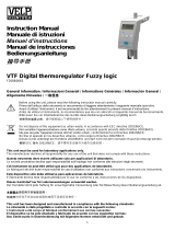


