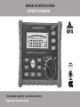
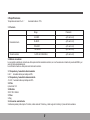
KPS TL300 El manual del propietario
- Categoría
- Medir, probar
- Tipo
- El manual del propietario

300V
Comprobador digital de la resistencia de tierra
Digital earth resistance tester
MANUAL DE INSTRUCCIONES
INSTRUCTION MANUAL

Contenidos
1. Seguridad………………………..................................................................................................1
2. Descripción.……………………..................................................................................................2
2.1 Descripción del medidor…………………….............................................................................2
2.2 Pantalla…………………….......................................................................................................5
3. Especificaciones……………………...........................................................................................7
3.1 Escalas y precisión…………...................................................................................................7
3.2 Método de medición……………..............................................................................................7
3.3 Temperatura y humedad de funcionamiento……………………..............................................7
3.4 Temperatura y humedad de almacenamiento………………...................................................7
3.5 Pilas……………....................................................................................................…...............7
3.6 Medidas………………...................................................................................................…........7
3.7 Peso…………….....................................................................................................……..........7
3.8 Accesorios…………….................................................................................................…........7

4. Instrucciones de funcionamiento……………..........................................................................8
4.1 Comprobación de la tensión de tierra…………….................................................................8
4.2 Comprobación de la resistencia de tierra mediante el método de dos electrodos…............8
4.3 Comprobación de la resistencia de tierra mediante el método de tres electrodos…..........10
4.4 Almacenamiento de datos ………..................................................................................….12
4.5 Lectura de datos………….......................................……….................................................12
4.6 Medición REL….…………………........................................................................................13
4.7 Medición MAX/MIN/AVG……………....................................................................…........…13
4.8 Eliminación de datos……………….................................................................................….13
4.9 Retroiluminación………………............................................................................................13
4.10 Auto-apagado…………………….......................................................................................13
5. Sustitución de las pilas………………....................................................................................14

1
1. Seguridad
El comprobador de resistencia de tierra (de aquí en adelante nos referiremos a él como medidor), que cumple con el requerimiento GB4793.1
en materia de seguridad para instrumentos electrónicos de medición, está diseñado y fabricado de acuerdo con los estándares de seguridad
EN61010-1, EN61010-2-030, calificado con grado de contaminación 2, y la máxima tensión que puede comprobar no puede exceder la
CAT III 300V.
El manual de usuario incluye precauciones y normas de seguridad, así como instrucciones de utilización del medidor para evitar accidentes o
lesiones personales y mantener el equipo en buenas condiciones. Por tanto, por favor lea este manual antes de utilizar el medidor y cumpla
con las instrucciones de funcionamiento que contiene. El no cumplimiento de las instrucciones del manual puede causar daños personales
o daños al medidor. La protección quedará inhabilitada si se utiliza de forma no especificada por el fabricante.
Símbolos de seguridad
Peligro: operación inapropiada que causará lesiones severas o mortales.
Advertencia: operación inapropiada que causará lesiones severas o mortales.
Precaución: operación inapropiada que causará lesiones personales o daños en el medidor.
Equipo protegido mediante doble aislamiento o aislamiento reforzado.
CAT III (categoría de medición III): Adecuado para la comprobación o medición de circuitos conectados a la parte de distribución de la
instalación de baja tensión del edificio.
Peligro
Compruebe si la rueda selectora está en la posición correcta antes de realizar la medición.
Nunca utilice el medidor cerca de gas explosivo, vapor o polvo.
Nunca conecte los cables o puntas con las manos mojadas o cuando la superficie del medidor esté húmeda.
No toque los cables de prueba o las puntas durante la medición
No abra la tapa de las pilas cuando el medidor esté en uso.
Advertencia
Nunca realice mediciones si detecta anormalidades en el equipo, como por ejemplo si la carcasa está dañada y la parte metálica del medidor o los cables
están pelados.
Nunca sustituya o modifique partes del medidor por su cuenta. Si el medidor está dañado, envíelo a sus proveedores locales para que lo examinen y reparen.
No cambie las pilas si la superficie del medidor está húmeda.
Asegúrese de colocar la rueda selectora en “OFF” y desconectar los cables de prueba antes de cambiar las pilas.
.

2
Precaución
El uso de este instrumento en un ambiente con la presencia de campos electromagnéticos de radio frecuencia con fuerte emisión
(aproximadamente 3V/m) podría influir en la precisión de las mediciones. El resultado medido podría desviarse considerablemente del valor real.
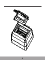
2. Descripción
2.1 Descripción del medidor
Precaución
Compruebe si la longitud total de los conectores de prueba esta introducida en los terminales antes de realizar la medición.
Retire las pilas del instrumento si no va a ser utilizado o va a ser almacenado durante un periodo largo.
No exponga el medidor a la luz del sol, alta temperatura, humedad o condensación.
Limpie el medidor con disolventes neutros o paños húmedos en vez de disolventes orgánicos o corrosivos.
Guarde el medidor únicamente si está seco.
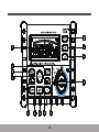
(1) Rueda selectora
El medidor se utiliza para medir la resistencia de puesta a tierra de los cables de alimentación, los cables de distribución de una habitación,
equipos o aparatos eléctricos, y puede realizarse mediante dos métodos: dos polos o tres polos. También puede utilizarse para medir la tensión
de tierra.
Su amplia pantalla digital LCD y la retroiluminación facilitan al usuario leer la información. Además, el medidor es capaz de almacenar hasta
100 grupos de datos de medición, que no se perderán ni en caso de corte de la fuente de alimentación para que el usuario pueda consultar
fácilmente datos históricos. Por otra parte, el medidor también permite la lectura de valores máximos, mínimos, promedios y relativos. Está
provisto de función de auto-apagado.
Se utiliza para seleccionar entre medición de la tensión de tierra, de la resistencia mediante el método de dos polos o medición de la
resistencia mediante el método de tres polos.
(2) Tecla ASP
Se utiliza para activar o desactivar la función de auto-apagado.
(3) Tecla LIGHT
Se utiliza para encender o apagar la luz de fondo.
(4) Tecla CLEAR
Se utiliza para borrar datos.
(5) LCD
Para la visualización de los datos obtenidos y los diferentes símbolos.

3

4
(6) Tecla READ
Se utiliza para leer los datos obtenidos.
(7) Tecla MEMO
Se utiliza para almacenar los datos obtenidos
(8) Tecla de medición
Se utiliza para empezar o interrumpir la medición de la resistencia.
(9) Tecla
Se utiliza para seleccionar una posición de memoria para almacenar
datos obtenidos.
(10) Tecla MAX/MIN/AVG
Se utiliza para cambiar entre la medición de máximos, mínimos
y promedios.
(11) Tecla ENTER
Se utiliza para confirmar el almacenamiento o lectura de datos.
(12) REL
Se utiliza para seleccionar una medición relativa
(13) Tecla
Se utiliza para seleccionar una posición de memoria
para almacenar datos obtenidos.
(14) Terminal E
Se utiliza para conectar a la toma tierra.
(15) Terminal P/S
Se utiliza para conectar a una toma de tierra auxiliar.
(16) Terminal C/H
Se utiliza para conectar a una toma de tierra auxiliar.

5
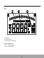
2.2 Pantalla LCD
1Barra simuladora
2Visualización de datos obtenidos
3Visualización de posición de memoria utilizada para el almacenamiento de datos
Descripción de los símbolos en la pantalla LCD:
TEST se está realizando un test
LIMIT se ha excedido el límite

6
MAX Máximo
MIN Minimo
AVG Promedio
REL Medición relativa
READ Lectura de datos
MEMO Los datos se están guardando en la memoria
USED Existen datos en la memoria.
2POLE Se está utilizando el método de los dos polos para la medición de la resistencia.
3POLE Se está utilizando el método de los tres polos para la medición de la resistencia.
V Voltio (Tensión)
KΩ Ohm (resistencia)
Se ha iniciado el proceso de auto-apagado
Batería baja
Identificación de la toma
Corriente alterna
Para advertencias y precauciones

7
3. Especificaciones
Temperatura del aire: 23 ± 5 Humedad relativa: <75%
Resistencia tierra
0~29.99Ω ±(2% lect.+6 d)
1.00~4000Ω ±(4% lect.+4 d)
3.2 Método de medición
La conversión constante de corriente se utiliza para medir la resistencia de tierra, con una frecuencia de corriente de prueba de 800Hz y un
valor de 3mA aproximadamente.
La rectificación media se utiliza para medir la tensión de tierra.
30~99.9Ω ±(3% lect.+3 d)
100~999Ω ±(3% lect.+3 d)
3.1 Precisión
Range Precisionh
50Hz/60Hz ±(2% lect.+4 d)
Tensión de tierra 0~200V AC
3.3 Temperatura y humedad de funcionamiento
0~40 humedad relativa por debajo de 85%
3.4 Temperatura y humedad de almacenamiento
-10~50 , humedad relativa por debajo de 85%
3.5 Pilas
6 pilas AAA 1.5V
3.6 Medidas
330 X 125 X 265mm
3.7 Peso
3.45kg
3.8 Accesorios suministrados
3 cables de prueba (cable rojo de 15 metros, cable verde de 10 metros, y cable negro de 5 metros), 2 picas de tierra auxiliares.

8
4. Instrucciones de funcionamiento
Antes de utilizar el medidor, compruebe la carga de la pila encendiendo el equipo y comprobando si aparece en pantalla el símbolo .
Si aparece dicho símbolo, sustituya las pilas siguiendo los pasos descritos en el capítulo “Sustitución de las pilas”.
4.2 Como medir la resistencia de la tierra por el método de los dos polos
Si existe un elemento puesto a tierra, como metales enterrados (tuberías metálicas etc), tierras comunes de fuentes de alimentación
comercial o pararrayos en edificios altos, se utilizan como polo auxiliar en este método en lugar de picas de tierra auxiliares.
Peligro
Durante la medición de la tensión de tierra, no exceda la tensión de 220VAC en los terminales de medición.
Durante la medición de la resistencia de tierra, podría darse una tensión de 50V entre los terminales E y S o entre los
terminales E y C, por lo que debe protegerse frente a un shock eléctrico.
4.1 Medición de la tensión de tierra
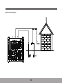
Gire la rueda selectora a la posición ~VE e introduzca los extremos de los cables de prueba en los terminales E y S, conectando los otros
extremos en paralelo a ambos lados de la fuente de tensión o resistencia. Si existe tensión, se mostrará en la pantalla LCD.

9
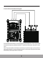
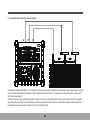
(1) Esquema de conexión para la prueba

10
(2) Medición de la tensión de tierra
La medición de la tensión de tierra debe realizarse antes de medir la resistencia de la tierra para comprobar el valor de la tensión
en tierra, ya que una tensión mayor a 10V puede causar errores mayores en la medición de la resistencia de la tierra. En este caso,
desconecte el objeto medido de la fuente de alimentación y espere a la caída de tensión de tierra para realizar otra medición.
(3) Medición de la resistencia de tierra
Gire la rueda a la posición 2 POL y presione la tecla MEASURE para empezar la medición, con la luz LED encendida y brillando.
Cuando la medición finaliza automáticamente, se emitirá un sonido, la luz LED se apagará y los datos se mantendrán
automáticamente en la pantalla.
Atención: La indicación >LIMIT 4000Ω en la pantalla advierte de que la resistencia de puesta a tierra de la toma auxiliar es
tan elevada que el medidor no es capaz de inyectar corriente. Compruebe si los cables de prueba se han soltado y el valor
de la resistencia de tierra de la pica de tierra auxiliar.
(4) Valor medido
Re, valor de la resistencia de tierra medido por el método de los dos polos, es la suma de re, la resistencia de tierra de la pica
auxiliar, y RX, la resistencia real del objeto medido; Por lo tanto, RX=Re-re, significa que la resistencia real del objeto medido
es igual a Re menos re.
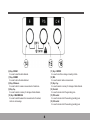
4.3 Medición de la resistencia por el método de los tres polos
Se utiliza el método de la caída de potencial para medir la resistencia de la tierra. La resistencia de tierra se calcula inyectando inicialmente
una corriente nominal (I) entre E, el objeto medido (la toma a tierra) y C, la pica de corriente y midiendo a continuación la
diferencia de potencial (V) entre E y P, la pica de tensión.

11
(1) Conecte los cables de prueba al medidor de la forma siguiente
Clave de forma profunda las picas auxiliares P y C en línea recta y asegúrese de que están separadas entre 5 y 10 metros. Conecte los extremos
de los cables de prueba (negro, rojo y verde) desde los terminales E, P, C respectivamente, al objeto a prueba, a la pica auxiliar P y a la pica
auxiliar C.
Atención: Coloque las picas auxiliares en zonas húmedas; si no existe otro tipo que no sea arcilla, arena o grava, que son secas, rocíelas con
algo de agua para humedecerlas; en caso de que esté realizando una medición en un suelo de cemento, coloque las picas de tierra auxiliares
de forma horizontal y rocíelas con agua o cúbralas con un trapo húmedo.

12
(2) Medición de la tensión de tierra
La medición de la tensión de tierra debe realizarse antes de medir la resistencia de la tierra para comprobar el valor de la tensión en tierra, ya
que una tensión mayor a 10V puede causar errores mayores en la medición de la resistencia de la tierra. En este caso, desconecte el objeto
medido de la fuente de alimentación y espere a la caída de tensión de tierra para realizar otra medición.
(3) Medición de la resistencia de tierra
Gire la rueda a la posición 3 POL y presione la tecla MEASURE para empezar la medición, con la luz LED encendida y brillando. Cuando la
medición finaliza automáticamente, se emitirá un sonido, la luz LED se apagará y los datos se mantendrán automáticamente en la pantalla.
Atención: La indicación >LIMIT 4000Ω en la pantalla advierte de que la resistencia de puesta a tierra de las picas auxiliares es tan
elevada que el medidor no es capaz de inyectar corriente. Compruebe si los cables de prueba se han soltado y el valor de la
resistencia de tierra de las picas de tierra auxiliares. Durante la medición, si los cables de prueba están entrelazados o conectados
entre sí, se producirá un error en la medida, con lo cual asegúrese de que se realiza la medición con los cables separados.
Además, una resistencia de tierra de las picas auxiliares muy elevada conllevará un error inadmisible en la medición con lo que ha
de clavar profundamente las picas auxiliares P y C en un lugar húmedo para asegurar una buena conexión.
4.4 Almacenamiento de datos
El medidor es capaz de almacenar hasta 100 grupos de medición de datos que no se perderán incluso en caso de corte de la fuente de alimentación.
(1) Cuando el medidor esté en modo de espera, presione MEMO para acceder a la pantalla de almacenamiento de datos con la palabra “MEMO”
brillando en la esquina inferior derecha de la pantalla LCD; Si la posición de memoria seleccionada ha sido usada para almacenar algún otro
resultado, “USED” se mostrará en la pantalla LCD. Para salir del modo almacenamiento de datos presione MEMO de nuevo.
(2) Presione “ENTER” brevemente para cambiar un bit de la posición de la memoria y para cambiar 10-bit y explorar la posición de la memoria
presione o
(3) Presione “ENTER” durante 2 segundo para almacenar un grupo de datos en la memoria. En caso de que existan datos guardados previamente,
los datos actuales sobrescribirán los datos anteriores.
(1) Cuando el medidor esté en modo de espera presione MEMO para acceder a la pantalla de almacenamiento de datos con la palabra “MEMO”
brillando en la esquina inferior derecha de la pantalla LCD; Si la posición de memoria seleccionada ha sido usada para almacenar algún otro
resultado, “USED” se mostrará en la pantalla LCD. Para salir del modo almacenamiento de datos presione MEMO de nuevo.
(2) Presione “ENTER” brevemente para cambiar un bit de la posición de la memoria y para cambiar 10-bit y explorar la posición de la memoria
presione o
4.5 Lectura de datos
La función de lectura de datos del medidor permite comprobar el histórico de mediciones guardadas en el instrumento.

13
3Presione “ENTER” durante 2 segundos para leer un grupo de datos en la memoria si existen datos almacenados previamente.
4.6 REL — Medición relativa
La medición relativa es seleccionable únicamente cuando el instrumento se utiliza para medir la resistencia de tierra. Presione la tecla REL
para cambiar entre modo de medición relativo y modo normal o viceversa.
1En el modo de medición relativa, el símbolo “REL” se muestra en la pantalla LCD y la lectura mostrada se almacena en la memoria
como referencia. En la siguiente medición relativa, lo que la pantalla LCD muestra es la diferencia entre el valor medido y el valor de
referencia. Esto es, lectura mostrada= valor medido- valor de referencia.
2Mientras la medición normal de resistencia de tierra se está realizando, no se permite acceder al modo REL.
3No se permite establecer el modo REL cuando los datos están siendo leídos o almacenados.
4No se permite acceder al modo REL cuando la lectura mostrada excede el límite.
4.7 Medición MAX/MIN/ AVG
Presione la tecla MAX/MIN/AVG para cambiar los modos entre mediciones de máximos, mínimos, promedio y la medición normal.
El símbolo correspondiente se mostrará en la pantalla LCD.
1Cuando se selecciona MAX, la pantalla LCD muestra el valor máximo de los datos.
2Cuando se selecciona MIN, la pantalla LCD muestra el valor mínimo de los datos.
3 Cuando se selecciona AVG, la pantalla LCD muestra el valor promedio de los datos.
4.8 Borrado de datos
Los datos pueden ser borrados al presionar READ o MEMO. Presione CLEAR brevemente para borrar los datos almacenados en la
posición de memoria indicada y presione de forma continuada para borrar todos los datos almacenados.
4.9 Retroiluminación
Presione LIGHT para encender o apagar la luz de fondo. Además, se apagará automáticamente 15 segundos después de haber sido encendida.
4.10 Auto-apagado
Presione ASP para empezar o detener el auto-apagado. El símbolo que se muestra en la pantalla LCD muestra que la función de
auto-apagado ha empezado y si este símbolo desaparece significa que la función se ha detenido. En caso de que no se realice ninguna
operación en los 15 minutos posteriores a la activación del Auto-apagado, el medidor entrará en modo descanso y se emitirá un sonido
para indicar esa situación. Presione cualquier tecla para encender el medidor de nuevo. Asegúrese de cambiar el interruptor a la posición
“OFF” si el medidor no va ser utilizado durante un período largo de tiempo.

14
5. Sustitución de las pilas
Atención
Nunca mezcle pilas nuevas con usadas.
Preste atención a la polaridad de las pilas a la hora de cambiarlas.
Peligro
Nunca cambie las pilas mientras el medidor esté húmedo.
Nunca cambie las pilas mientras el medidor esté siendo utilizado. Apague el instrumento y desconecte los cables de prueba
y las picas de tierra antes de realizar la sustitución para evitar shock eléctrico.
5.1 Desatornille la tapa de las pilas y retírela.
5.2 Cambie las pilas viejas por unas nuevas y preste atención a la polaridad.
5.3 Vuelva a poner la tapa de las pilas y atorníllela.

15

KPS SOLUCIONES EN ENERGÍA, S.L.
Parque Empresarial de Argame,
C/Picu Castiellu, Parcelas i-1 a i-3
E-33163 Argame, Morcín
Asturias, España, (Spain)

Contents
1. Safety………………………...................................................................................................1
2. Description.……………………..............................................................................................2
2.1 Meter Description……………………...................................................................................2
2.2 Display……………………...................................................................................................5
3. Specifications……………………...........................................................................................7
3.1 Range and Precision…………............................................................................................7
3.2 Measurement Method…………….......................................................................................7
3.3 Using Temperature and Humidity……………………...........................................................7
3.4 Storing Temperature and Humidity………………................................................................7
3.5 Battery……………....................................................................................................….......7
3.6 Volume………………...................................................................................................…....7
3.7 Weight…………….....................................................................................................……...7
3.8 Accessories…………….................................................................................................…..7

4. Operation Instructions……………............................................................................………....8
4.1 Testing the Earth Voltage……………....................................................................................8
4.2 Testing the Earth Resistance by the bi-electrode method………………...............................8
4.3 Testing the Earth Resistance by the tri-electrode method……………….............................10
4.4 Data Storage ………..............................................................................................………..12
4.5 Data Reading………….......................................………......................................................12
4.6 REL Measurement….…………………................................................................................13
4.7 MAX/MIN/AVG Measurement……………....................................................................……13
4.8 Data Deletion………………............................................................................................….13
4.9 Back Light………………................................................................................................…..13
4.10 Auto Off……………………................................................................................................13
5. Battery Replacement………………...............................................................................…….14

1
1. Safety
The earth resistance tester (hereinafter referred to as meter) , which is up to GB4793.1, the requirement on the safety of electronic
measurement instruments, is designed and manufactured in accordance with EN 61010-1, EN61010-2-030 Safety Standard, regarded as
Grade 2 pollution, and the maximum voltage for the meter to probe can not exceed CAT III 300V.
The users’ manual includes cautions and safety regulations, which specifies the rules in usage of the meter to avoid personal injury accident
and long keep the meter in good condition, therefore, please read the manual before using the meter and adhere to the operation instructions
inside it, and inobservance of the manual in using the meter may cause personal injury or damage to the meter. Protection impairment if
used in a manner not specified by the manufacturer.
Safety Symbols
Danger: improper operation will cause severe or fatal injuries.
Warning: improper operation may cause severe or fatal injuries
Cautionimproper operation may cause personal injuries or damage to the meter
Equipment protected throughout by double insulation or reinforced insulation
CAT III (measurement category III): Applicable to test and measuring circuits connected to the distribution part of the
building’s low-voltage MAINS installation.
Danger
Check if the rotating switch is set to a proper position before measurement
Never use the meter in the vicinity of explosive gases, steam or dust.
Never connect wires or probes with wet hands or when the surface of the meter is humid.
Don’t touch the testing wires or probes in a measurement.
Don’t open the battery cover when the meter is working.
Warning
Never proceed a measurement under abnormalities, for example, the housing of the meter has been damaged so that the metal of the meter or wires are
naked.
Never replace the parts of the meter by yourself or modify it. Should the meter be damaged, return it tothe local dealers for examination or repair.
Don’t replace the batteries when the surface of the meter is humid.
Be sure to set the switch to “OFF” and disconnect the testing wires before replacing the batteries.

2
Caution:
Using this appliance in an environment with a strong radiated radio-frequency electromagnetic field (approximately 3V/m ), may influence its measuring
accuracy. The measuring result can be strongly deviating from the actual value.
2. Description
The meter is applicable to the testing of the earth resistance of the power supply wires, distribution wires inside a room, electrical equipment
or appliance, which can done in two measurement modes: Bi-poles or Tri-poles, and it also can be used to measure the earth voltage.
Large digital LCD and backlights applied to the meter facilitate users to read the information on LCD. Besides, the meter is capable of storing
up to 100 groups of measurement data, which will not be lost even in case of power cuts so that the user can easily consult the historical data.
In addition, the meter can also be used to measure maximum, minimum or average and measure relatively. Auto power-off function has been
provided for it.
2.1 Meter Description
(1) Rotating Switch
It is used to selection between the measurement of earth voltage, measurement of resistance in Bi-pole method or measurement of
resistance in Tri-pole method.
(2) Key of ASP
It is used to start or cease auto power-off function.
(3) Key of LIGHT
It is used to turn on or turn off the backlight.
(4) Key of CLEAR
It is used to clear away data.
(5) LCD
It is used to display the data obtained and different symbols.
Caution
Check if the total length of testing wires is inserted into the port before a measurement.
Take out of the batteries from the cartridge if the meter will not be used or will be stored for long.
Don’t expose the meter to sunlight, high temperature, humidity or dew
Clean the meter with neutral solvents or wet cloth instead of abrasives or organic solvents
Lay the meter in store only when it is dry.

3

4
(6) Key of READ
It is used to read the data obtained.
(7) Key of MEMO
It is used to store the data obtained.
(8) Key of Measure
It is used to start or cease a measurement of resistance.
(9) Key of
It is used to select a memory for storage of data obtained.
(10) Key of MAX/MIN/AVG
It is used to switch between the measurement of maximum,
minimum and average.
(11) Key of ENTER
It is used to confirm a storage or reading of data.
(12) REL
It is used to select relative measurement.
(13) Key of
It is used to select a memory for storage of data obtained.
(14) E socket
It is used to connect with the grounding pole.
(15) P/S socket
It is used to connect with the auxiliary grounding pole.
(16) C/H socket
It is used to connect with the auxiliary grounding pole.

5
2.2 LCD
1Simulating bar
2Display of data obtained
3Display of memory used for data storage
Descriptions of symbols on LCD:
TEST a test is being progressed
LIMIT limit has been exceeded

6
MAX Maximum
MIN Minimum
AVG Average
REL Relative measurement
READ Data reading
MEMO Data is being put into a memory
USED There are data in memories.
2POLE Bi-pole method is being used for measurement of resistance.
3POLE Ti-pole method is being used for measurement of resistance.
V Volt(voltage)
KΩ Ohm(resistance)
Auto power-off has been started with the symbol on
Battery is low with the symbol on
For socket identification
Alternating current
For warnings and cautions

7
3. Specifications
Air temperature: 23 ± 5 Relative humidity: <75%
3.1 Range Specifications
Range Precisionh
Earth Ground Resistance
Earth Voltage AC 0~200V50Hz/60Hz ±(2% rdg +4d)
0~29.99Ω ±(2%rdg+6d)
1.00~4000Ω ±(4% rdg +4d)
3.2 Measurement method
Constant Current Conversion is used for the measurement of earth resistance, with the frequency of the testing current about 800HZ and
the size about 3mA.
Average rectification is used for the measurement of earth voltage.
3.3 Temperature and humidity for measurement
0~40relative humidity under 85%
3.4 Temperature and humidity for keeping the meter
-10~50, relative humidity under 85%
3.5 Battery
6x 1.5V AA batteries
3.6 Volume
330 X 125 X 265mm
3.7 Weight
3.45kg
3.8 Supplied accessories
3 test leads (one 15-meter-long red lead, one 10-meter-long green lead and one 5-meter-long black lead ) , 2auxiliary earth bars
30~99.9Ω ±(3%rdg+3d)
100~999Ω ±(3%rdg+3d)

8
4.Operation Instruction
Danger
In measurement of earth voltage, do not exert voltage above AC220V on the measurement port.
In measurement of earth resistance, there will occur potential of about 50 V between port E and S or between ports E and C,
therefore, protect yourself from electrical shock.
Before using the meter, check the electricity in the battery by turning on the meter, checking if there is “ ” on display and replace the
battery by following the steps described in Chapter “Replacement of the battery” if the symbol exists.
4.1 Measurement of earth voltage
Rotate the switch to ~VE position, insert the end of meter cable into sockets E and S, with another end of meter cable connected to either
end of voltage source or resistance load in parallel way to measure . If there exists voltage, it will be displayed on LCD.
4.2 How to measure earth resistance by Bi-pole method
Existing earth pole, such as buried metals (metal water pipe etc) , common earth of the commercial power supply or lightning rods of high
buildings, instead of auxiliary earth bars are used as auxiliary pole in this method.

9
(1) Test Connection Diagram

10
(2) Measurement of earth voltage.
Earth voltage measurement should be done before measurement of earth resistance to check the amount of earth
voltage, as voltage more than 10 V is likely to cause larger error in the measurement of earth resistance. In this case, cut
the measured object from the power supply and wait until the earth voltage drop for another measurement.
(3) Measurement of earth resistance
Rotate the switch to 2 POL position, press down the key of MEASURE to start the measurement, with the key
LED turned on and glittering. When the measurement comes to the end automatically, the buzzer will give a sound, the
key LED will go off and the data will be held automatically.
Attention: LIMIT4000Ω displayed on LCD warns that the auxiliary earth resistance of the auxiliary earth
rods is so high that the current can not flow across the meter. Check if the test leads become loose and the amount
of the earth resistance of the auxiliary earth rods.
(4) Value measured
Re, value of the earth resistance measured by Bi-pole method, equals the sum of re, the earth resistance of earth
rods, and RX, the real earth resistance of the object measured; therefore, RX=Re-re, meaning that the real resistance of
the object measured equals Re minus re.
4.3 Measurement of the resistance by Tri-pole method
Potential Drop Method is used by the meter for the measurement of the earth resistance. Particularly, RX, the earth
resistance is figured out by first allowing I, the rated current, to flow between E, the object measured (the earth rods) and
C, the current pole, then measuring V, the potential difference between E and P, the voltage pole.

11
(1) Connect the test leads to the meter as follows
Drive deep the Auxiliary Earth Bars P, C in straight line into the ground and ensure that the bars are between 5 and 10 meters apart. Connect
ends of the test leads (black, red and green) , which respectively from the ports E, P, C, separately to the object measured, auxiliary earth
rod P and auxiliary earth C.
Attention: Drive the auxiliary rods where the earth is damp; in case that no other earth but clay, sand or gravel, which are dry, are available,
spray some water onto them to keep them damp; in case the measurement is performed on a concrete floor, place the auxiliary earth rods
horizontally and spray some water onto them or cover them with damp cloth.

12
(2) Measurement of earth voltage
Earth voltage measurement should be done before measurement of earth resistance to check the amount of earth voltage, as voltage more
than 10 V is likely to cause larger error in the measurement of earth resistance. In this case, cut the measured object from the power supply
and wait until the earth voltage drop for another measurement.
(3) Measurement of earth resistance
Rotate the switch to 3 POL position, press down the key of MEASURE to start the measurement, with the key LED turned on and glittering.
When the measurement comes to the end automatically, the buzzer will give a sound, the key LED will go off and the data will be held
automatically.
Attention: LIMIT4000Ω displayed on LCD warns that the auxiliary earth resistance of the auxiliary earth rods is so high that the
current can not flow across the meter. Check if the test leads become loose and the amount of the earth resistance of the auxiliary
earth rods. In a measurement, test leads twisted together or becoming contacted each other will cause error in the measurement;
therefore, make sure that a measurement is done when the test leads are separate. Besides, too much auxiliary earth resistance will
bring unacceptable error to the measurement, therefore, respectively bury deep auxiliary earth rods such as P and C in too wet sites
and ensure good connection in each joint.
4.4 Data Storage
The meter is capable of storing up to 100 groups of measurement data, which will not be lost even in case of power cuts.
1When the meter is standing b y, press MEMO to call the display for data storage, with “MEMO” glittering at the lower right corner of LCD;
should the existing memory has been used for storage of other data, “USED” would be shown on LCD when pressing MEMO to exit data
storage.
2Press “ENTER” briefly to switch A bit of a memory position and 10-bit and the memory position can be scanned by pressing “ ” or “ ”.
3Press “ENTER” for 2 seconds to store a group of data in a memory and in case that there are data stored before in the memor y, the
current data will cover the previous data.
4.5 Data Reading
Data reading function of the meter allows you to check the historical measurement stored in the meter.
1When the meter is standing b y, press MEMO to call the display for data storage, with “MEMO” glittering at the lower right corner of LCD;
should the existing memory has been used for storage of other data, “USED” would be shown on LCD when pressing MEMO to exit data
storage.
2Press “ENTER” briefly to switch A bit of a memory position and 10-bit and the memory position can be scanned by pressing “ ” or “ ”.

13
3Press “ENTER” for 2 seconds to read a group of data in a memory if there are data stored before in the memory
4.6 REL—Relative Measurement
Relative measurement can be accessible only when the tester is used for measurement of earth resistance. Press REL to switch the relative
measurement mode with the normal one or vice versa.
1Under relative measurement mode, the symbol “REL” is shown on LCD and the existing reading is stored in the memory for future
reference. In the following relative measurement, what the LCD displays is the difference between the input value and the reference
value, that is, existing reading=input value-reference value.
2Under normal measurement of earth resistance, it is not allowed to enter RE L mode when the measurement is progressing.
3It is not allowed to enter REL mode when the data is being read or stored.
4It is not allowed to enter REL mode when the existing reading exceeds the limit.
4.7 MAX/MIN/AVG Measurement
Press the key of MAX/MIN/AVG to switch the modes between the measurements of maximum, minimum, average and normal, corresponding
to each of which a symbol is shown on LCD.
1When MAX is selected, the LCD shows the maximum of all the data.
2When MIN is selected, the LCD shows the minimum of all the data.
3When AVG is selected, the LCD shows the average of all the data.
4.8 Data Deletion
The data can be deleted when READ or MEMO is pressed down. Press CLEAR briefly to delete the data stored in the existing position and
press it long to delete all the data stored.
4.9 Backlight
Press LIGHT to turn on or turn off the backlight and it will go off automatically 15 seconds after it is turned on.
4.10 Auto off
Press ASP to start or cease Auto-off. The symbol “ ” shown on the LCD means the Auto-off function has been started and disappearance
of the symbol means that the function has been ceased. In case that no operation is performed within 15 minutes after Auto-off is on, the
meter goes into sleeping status and the buzzer will give sound to remind of this . Press any key to wake the meter up. Be sure to set the
switch to “OFF” if the meter will not be used for long.

14
5. Replacement of Batteries
Attention
Never mingle new batteries with old ones.
Pay attention to the polarity of the batteries in replacements.
Danger
Never replace the batteries while the meter is damp.
Never replace the batteries while the meter is being used. Switch off the meter and disconnect the test leads and earth rods
before replacements to avoid electrical shock.
5.1 Unscrew the battery cover and remove it.
5.2 Replace the old batteries with new one and pay attention to their polarities.
5.3 Put back the battery cover and screw it.

15

KPS SOLUCIONES EN ENERGÍA, S.L.
Parque Empresarial de Argame,
C/Picu Castiellu, Parcelas i-1 a i-3
E-33163 Argame, Morcín
Asturias, España, (Spain)
-
 1
1
-
 2
2
-
 3
3
-
 4
4
-
 5
5
-
 6
6
-
 7
7
-
 8
8
-
 9
9
-
 10
10
-
 11
11
-
 12
12
-
 13
13
-
 14
14
-
 15
15
-
 16
16
-
 17
17
-
 18
18
-
 19
19
-
 20
20
-
 21
21
-
 22
22
-
 23
23
-
 24
24
-
 25
25
-
 26
26
-
 27
27
-
 28
28
-
 29
29
-
 30
30
-
 31
31
-
 32
32
-
 33
33
-
 34
34
-
 35
35
-
 36
36
-
 37
37


KPS TL300 El manual del propietario
- Categoría
- Medir, probar
- Tipo
- El manual del propietario
En otros idiomas
- English: KPS TL300 Owner's manual