KPS TL320 El manual del propietario
- Categoría
- Medir, probar
- Tipo
- El manual del propietario

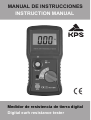
MANUAL DE INSTRUCCIONES
INSTRUCTION MANUAL
Medidor de resistencia de tierra digital
Digital earh resistance tester

Índice
1. Introducción........................................
2. Notas de seguridad.............................
3. Características....................................
Especificaciones.................................4.
5. Maintenimiento....................................
6. Métodos de medición..........................
Página
1
2
3
4-6
7
8-12

-1-
1. Introducción
Nota
Este medidor ha sido diseñado y probado de acuerdo
a los requerimientos de seguridad para aparatos
electrónicos de medida IEC/EN 61010-1 CAT IV 200V,
IEC 61557-1, IEC 61557-5, EN61326-1 y otros
estándares de seguridad. Siga todas las advertencias
para garantizar la seguridad en las operaciones.
• Aplicación:
El comprobador de resistencia de tierra se utiliza
para medir los ohmios (Ω) de una instalación de
toma a tierra en edificios (residenciales, oficinas,
laboratorios, hospitales), locales con servidores
informáticos, instalaciones militares, instalaciones
de comunicaciones, torres de radio y cable, etc.
Se utiliza para determinar si la tierra (o suelo) es
un buen conductor de electricidad.

-2-
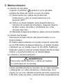
2. Notas de seguridad
• Lea la información de seguridad siguiente con
detenimiento antes de empezar a operar con el
medidor.
• Utilice el equipo únicamente como se especifica
en este manual: de otro modo la protección
proporcionada por el medidor puede quedar
inhabilitada.
• Calificación de las condiciones ambientales:
(1) Instalación de categoría IV 200V.
(2) Grado de contaminación 2.
(3) Altitud de hasta 2000 metros.
(4) Humedad relativa máxima 80%
(5) Temperatura ambiental 0º-40ºC
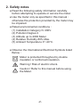
• Observe los símbolos eléctricos internacionales
listados más abajo:
El medidor está protegido mediante doble
aislamiento o aislamiento reforzado.
¡Advertencia! Riesgo de shock eléctrico.
¡Precaución! Consulte este manual antes
de utilizar el medidor.

-3-
3. Características
* Frecuencia: 820Hz
* Capaz de medir la tensión de tierra.
* La corriente de medición de 2mA permite la
comprobación de la resistencia de tierra sin hacer
disparar los dispositivos de corriente de fuga a tierra
en los circuitos bajo ensayo.
* Se suministran como accesorios estándar los cables
de prueba necesarios para el sistema de medida
simplificado de dos polos.
* Ajuste a 0Ω.
* Función de retención de datos.
* Funcionamiento con batería.
* Indicador de batería baja.
* Estándares de seguridad:
IEC/ EN 61010-1 CAT IV 200V
IEC 61557-1
IEC 61557-5
EN 61326-1

-4-
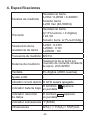
4. Especificaciones
Escalas de medición
Resistencia tierra
0-20Ω / 0-200Ω / 0-2000Ω
Tensión tierra
0-200 Vac (40-500Hz)
Precisión
Resistencia tierra
±(1.5% lectura + 2 dígitos)
ó ±0.1Ω
Tensión tierra ±(1% lect+2díg.)
Resolución de la
resistencia de tierra
0-20Ω : 0.01Ω
0-200Ω : 0.1Ω
0-2000Ω : 1Ω
Frecuencia de medición 820 Hz
Sistema de medición
Resistencia de la tierra por
inversión de corriente constante
de aprox. 2mA 820Hz
Pantalla 3½ dígitos (2000 cuentas)
Ajuste a 0Ω √
Indicador circuito abierto
El LED estará apagado
Indicador batería baja El símbolo aparece
en pantalla
Indicador retención
de datos
El símbolo aparece
en pantalla
Indicador sobreescala “1”(MSD)
Dimensiones 221(L) × 110(A) × 57(P)mm
HOLD

-5-
Peso (pilas incluidas) Aprox. 600g
Fuente de alimentación
6 x 1.5V (AA)
Estándar de
seguridad
IEC/EN 61010-1 CAT IV 200V
IEC 61557-1
IEC 61557-5
EN 61326-1
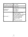
Accesorios
Manual de instrucciones
Cables de prueba
(rojo-15m, amarillo-10m, verde-5m)
Picas de tierra auxiliares
Punta de prueba para
medición simplificada
Correa de mano
Pilas
Estuche de transporte

-6-
●Error de operación máximo
El error operativo (B) es un error obtenido en las
condiciones de funcionamiento nominales, y calculado
con el error intrínseco (A), que es un error del instrumento
utilizado, y el error (En) debido a variaciones.
B=±(│A│+1.15 E2
2+E3
2+E4
2+E5
2)
A: error intrínseco
E2: Variación debido al cambio de la tensión de alimentación.
E3: Variación debido al cambio de temperatura.
E4: Variación debido a la tensión de interferencia cíclica.
E5: Variación debido a la resistencia de los cables de prueba
y del electrodo de tierra auxiliar.
●Rango para conservar el error de operación máximo.
Rango de medición dentro de la cual se aplica el
máximo error de operación (±30%).
Escala 20Ω : 5 ~ 19.99Ω
Escala 200Ω : 20 ~ 199.9Ω
Escala 2000Ω : 200 ~ 1999Ω
●Temperatura y humedad
Funcionamiento : 0°C~50°C ≤ 80%R.H.
Almacenamiento : -10°C~60°C ≤ 80%R.H.

-7-
5. Mantenimiento
●Cambio de las pilas
Cuando el símbolo aparece en la pantalla,
cambie las pilas del modo en que se indica:
(1) Desconecte los cables de prueba del
instrumento y gire la rueda selectora a la
posición OFF.
(2) Utilice un destornillador para desatornillar los
tornillos de la tapa de la batería, después deslice
la tapa, saque las pilas y cámbielas por unas
nuevas (tipo AA).
(3) Reinstale la tapa de la batería y fíjela con los 2 tornillos.
●Cambio del fusible
Desmonte la tapa inferior del panel frontal con un
destornillador.
El fusible está localizado en la parte superior izquierda
de la PCB. Retire la tapa protectora y el fusible fundido.
Cámbielo por un fusible nuevo (0.1A/ 250V; 5x20mm),
después vuelva a colocar la tapa trasera. Monte la tapa
inferior y el panel frontal con un destornillador.
●Limpieza y almacenamiento
ADVERTENCIA
Para evitar shock eléctrico o daños al medidor,
no vierta agua en la carcasa.
Limpie periódicamente la carcasa con un trapo húmedo
y detergente; no utilice abrasivos o disolventes. Si el
equipo no va a ser utilizado durante períodos superiores
a 60 días, retire las pilas y almacénelas separadamente.

-8-
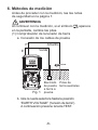
6. Métodos de medición
Antes de proceder con la medición, lea las notas
de seguridad en la página 1.
ADVERTENCIA
Al continuar con la medición, si el símbolo aparece
en la pantalla, cambie las pilas.
(1) Comprobación de la tensión de tierra
a. Conexión de los cables de prueba
b. Gire la rueda selectora hasta la posición
“EARTH VOLTAGE” (“tensión de tierra”).
A continuación presione la tecla TEST.
Fig. 1
Verde
Electrodo
de puesta
a tierra a
prueba
Picas de
tierra auxiliares
P
E
Amarillo

-9-
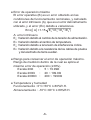
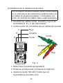
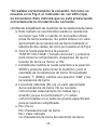
(2) Medición de la resistencia de tierra
Los resultados medidos pueden verse influenciados
por la inducción si las mediciones están hechas con
los cables de prueba trenzados o conectados uno
al otro. Al conectar los cables, deben estar separados.
a. Conecte los cables verde, amarillo y rojo a los
terminales E, P y C del instrumento
b. Cortocircuite los cocodrilos de los cables de prueba.
c. Seleccione la escala apropiada Ω
d. Presione el botón test y bloquee la medición.
e. Ajuste la rueda “0Ω ADJ” hasta que en
la pantalla se muestre cero.
Fig. 2
Rojo
Rojo
Amarillo
Amarillo
Verde Verde
C
P
E

-10-
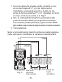
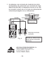
f.
Con los cables de prueba verde, amarillo y rojo
en los terminales E, P y C del instrumento,
conéctelos a la puesta a tierra a medir y a las
picas de tierra auxiliares P1 y C1 clavadas en tierra
en línea recta de acuerdo a la Fig.3.
g. Gire la rueda selectora hasta la escala adecuada,
presione el botón TEST para empezar la medición.
Los usuarios pueden presionar y girar el botón TEST
para realizar una prueba de larga duración si fuese necesario.
h. Tome la lectura
Nota: el procedimiento descrito arriba necesita repetirse
cada vez que se modifique la escala de resistencia Ω.
Fig. 3
Verde
Electrodo
de tierra
bajo ensayo
Picas de
tierra
auxiliares
P
E
Amarillo
RojoC
5~10m 5~10m

-11-
*Al realizar correctamente la conexión, tal como se
muestra en la Fig.3, el indicador de luz LED (roja)
se encenderá. Esto indicará que se está produciendo
correctamente la circulación de corriente.
a. Este método se recomienda cuando la resistencia
es mayor que 10Ω o cuando no es posible utilizar
picas de tierra auxiliares. Se podrá obtener un valor
aproximado de la resistencia de tierra mediante el
sistema de dos cables, tal como se muestra en la Fig.4.
b. Gire la rueda selectora a la posición
“EARTH VOLTAGE” (“tensión de tierra”) y presione
para iniciar la comprobación. Asegúrese de que la
tensión de tierra es menor a 10V.
c. Inicialmente cambie la rueda selectora a la posición
“200Ω”y presione para iniciar la medición y leer el
resultado de la resistencia de tierra. Si la pantalla
muestra “1” (MSD), cambie a la posición “2kΩ” y lea
la resistencia de tierra.
d. La lectura obtenida (Rx) es un valor aproximado
de la resistencia de tierra. No se necesita
cortocircuitar externamente los cables rojo y
amarillo ya que los terminales P y C están
cortocircuitados en el cable de prueba especificado
para la medición simplificada.
e. Rx= Re-re
Rx= Resistencia real de tierra
Re= Valor indicado
re= Resistencia de tierra del electrodo de tierra.
(3) Método simplificado de medición de la resistencia de tierra

-12-
f.
Al utilizarse una corriente de medición de 2mA,
el dispositivo de protección por corriente de fuga
diferencial (ELCB) no disparará incluso si se usa
la conexión a tierra de un circuito de alimentación
comercial protegido con un diferencial.
Fig. 4
Verde
re Rx
Electrodo de tierra
a prueba
Rojo
Donde se utiliza la tierra
de la red de suministro
eléctrico.
CPE
Rx=Re-re
Transformador
alimentación
Lado
secundario
Lado
primario
KPS SOLUCIONES EN ENERGÍA, S.L.
Parque Empresarial de Argame,
C/Picu Castiellu, Parcelas i-1 a i-3
E-33163 Argame, Morcín
Asturias, España, (Spain)

Index
1. Introduction........................................
2. Safety notes.......................................
3. Features.............................................
4. Specications.....................................
5. Maintenance.......................................
6. Measuring methods............................
Page
1
2
3
4-6
7
8-12

-1-
1. Introduction
Note
This meter has been designed and tested according
to CE Safety Requirements for Electronic Measuring
Apparatus. IEC/EN 61010-1 CAT IV 200V, IEC
61557-1, IEC 61557-5, EN 61326-1 and other
safety standards. Follow all warnings to ensure safe
operation.
●Application:
Earth Resistance Tester is used to measure the
ohms (Ω) of an earth grounding installation for
buildings (residential, ofce, labs, hospitals),
computer server rooms, military installations,
cellular sites, radio and cable towers, etc. It is used
to determine if the earth (or ground) is a good
conductor of electricity.

-2-
2. Safety notes
●Read the following safety information carefully
before attempting to operate or service the meter.
● Use the meter only as specied in this manual :
otherwise the protection provided by the meter may
be impaired.
●Rated environmental conditions :
(1) Installation Category IV 200V.
(2) Pollution Degree 2.
(3) Altitude up to 2000 Meter.
(4) Relative Humidity 80% Max.
(5) Ambient Temperature 0°~40°C.
●Observe the International Electrical Symbols listed
Below :
Meter is protected throughout by double
insulation or reinforced insulation.
Warning ! Risk of electric shock.
Caution ! Refer to this manual before using
the Meter.

-3-
3. Features
● Frequency : 820Hz.
●Capable of measuring earth voltage.
●2mA measuring current permits earth resistance
tests with tripping earth leakage current breakers in
the circuit under test.
●In addition to facilitating for precision measurement,
test leads for simplied two wire measuring system
also are supplied as standard Accessories.
● 0Ω adjustment.
● Data hold function.
●Battery operated.
●Low battery indication.
●Safety standard :
IEC/EN 61010-1 CAT IV 200V
IEC 61557-1
IEC 61557-5
EN 61326-1

-4-
4. Specications
Measuring ranges
Earth resistance
0-20Ω / 0-200Ω / 0-2000Ω
Earth voltage
0-200 Vac (40-500Hz)
Accuracy
Earth resistance
±(1.5%rdg+2dgt)
or ±0.1Ω, which is greater
Earth voltage ±(1%rdg+2dgt)
Earth resistance
resolution
0-20Ω : 0.01Ω
0-200Ω : 0.1Ω
0-2000Ω : 1Ω
Testing frequency 820 Hz
Measuring system
Earth resistance by constant
current inverter 820Hz approx
2mA.
Display 3½ digit (2000 counts)
0Ω adjustment √
Open circuit indication LED will be unlit
Low battery indication “ “symbol appears on the
display
Data hold indication “ HOLD “symbol appears on the
display
Over range Indication “1”(MSD)
Dimensions 221(L) × 110(W) × 57(D)mm

-5-
Weight
(battery included) Approx. 600g
Power source 1.5V (AA) × 6
Safety standard
IEC/EN 61010-1 CAT IV 200V
IEC 61557-1
IEC 61557-5
EN 61326-1
Accessories
Instruction manual
Test leads (red-15m, yellow-
10m, green-5m)
Auxiliary earth spikes
Simplied measurement
probe
Hand strap
Batteries
Carry case

-6-
● Maximum Operating Error
Operating error (B) is an error obtained within the
rated operating conditions, and calculated with the
intrinsic error (A), which is an error of the instrument
used, and the error (En) due to variations.
B=±(│A│+1.15 E2
2+E3
2+E4
2+E5
2)
A: Intrinsic error
E2: Variation due to changing the supply voltage
E3: Variation due to changing the temperature
E4: Variation due to series interference voltage
E5: Variation due to resistance of the probes and
auxiliary earth electrode resistance
● Range to keep the maximum operating error
Measurement range within which the maximum
operating error (±30%) applies.
20Ω Range : 5 ~ 19.99Ω
200Ω Range : 20 ~ 199.9Ω
2000Ω Range : 200 ~ 1999Ω
● Temperature & Humidity
Operating : 0°C~50°C ≤ 80%R.H.
Storage : -10°C~60°C ≤ 80%R.H.

-7-
5. Maintenance
●Battery replacement
When the symbol " " appears on the display,
replace with new batteries as follows :
(1) Disconnect the test leads from the instrument
and turn off the power.
(2) Use a screwdriver to unscrew the screws on
the battery cover then slide the cover, take out
the batteries and replace with new batteries (type
AA).
(3) Reinstall the battery cover and secure it with the
2 screws.
●Fuse replacement
Disassemble the bottom case from the front panel
with a screw driver.
The fuse is located on the upper left of the PCB.
Remove the protective cover and the blown fuse.
Replace with a new fuse (0.1A/250V ; 5x20mm),
then put the protective cover back. Assemble the
bottom case and the front panel with a screwdriver.
●Cleaning and storage
WARNING
To avoid electrical shock or damage to the meter,
do not get water inside the case.
Periodically wipe the case with a damp cloth and
detergent ; do not use abrasives or solvents.
If the meter is not to be used for periods of longer
than 60 days, remove the batteries and store them
separately.

-8-
6. Measuring methods
BEFORE PROCEEDING MEASUREMENT, READ
SAFETY NOTES ON PAGE 1.
WARNING
In proceeding with measurement, if " " symbol
appears on the display, replace with new batteries.
(1) Earth voltage check
a. Test leads connection
b. Turn the function switch to the "EARTH
VOLTAGE" position, then press the TEST
button to test.
Fig. 1
Green
Earth
Electrode
under test
Auxiliary
Earth
Spikes
P
E
Yellow

-9-
(2) Earth resistance measurement
The measured results may be inuenced by
induction if measurements are made with the Test
Leads twisted or connected to each other. When
connecting the probes, they should be separated.
a. Connect green, yellow and red test leads to
instrument terminals E.P.C.
b. Short-circuit the aligators of the test leads.
c. Select the appropriate Ω range.
d. Press the test button and lock.
e. Adjust the "0 Ω ADJ" dial until the display reads
zero.
Fig. 2
Red
Red
Yellow
Yellow
Green Green
C
P
E

-10-
f. Connect green, yellow and red test leads
to instrument terminals E, P and C with
auxiliary earth spikes P1, C1 stuck into earth
"IN A STRAIGHT LINE". (Fig. 3)
g. Turn the function switch to an appropriate
range, then press the TEST button to test.
Users can press and turn the TEST button to
do a long duration test if necessary.
h. Take the reading
Note : The above procedure needs to be repeated for
each Ω range selection.
Fig. 3
Green
Earth
Electrode
under test
Auxiliary
Earth
Spikes
P
E
Yellow
RedC
5~10m 5~10m

-11-
*Follow the proper connection such as Fig. 3, the
LED(red) indicator will lit. This proves a correct
current circulation is under its operation.
(3) Simplied earth resistance measurement method
a. This method is recommended where an earth
resistance higher than 10Ω is measured
or where it is not possible to drive auxiliary
earth spikes. An approximate value of earth
resistance can be obtained by the two wire
system where is shown in Fig. 4.
b. Rotary to function switch to "EARTH VOLTAGE"
position and press to test. Make certain that
earth voltage is less than 10V.
c. First rotary the function switch to "200Ω"
position and press to test, read earth resistance.
If the display shows "1" (MSD), switch to "2kΩ"
position and read earth resistance.
d. The reading obtained (Rx) is an approximate
earth resistance value. There is no need for
external shorting as P and C terminals are
shorted by using the test leads specied for the
Simplied measurement.
e. Rx = Re -re
Rx = True Earth Resistance
Re = Indicated Value
re = Earth Resistance of Earth Electrode.

-12-
f. Since measuring current is as low as 2 mA, the
earth leakage breaker (ELCB) does not trip
even if the earth side of the commercial power
supply with an ELCB is used.
Fig. 4
Green
re Rx
Earth
Electrode
under test
Red
Where earth for mains
power supply is used.
CPE
Rx=Re-re
Supply
Transformer
Secondary
side
Primary
side
KPS SOLUCIONES EN ENERGÍA, S.L.
Parque Empresarial de Argame,
C/Picu Castiellu, Parcelas i-1 a i-3
E-33163 Argame, Morcín
Asturias, España, (Spain)
-
 1
1
-
 2
2
-
 3
3
-
 4
4
-
 5
5
-
 6
6
-
 7
7
-
 8
8
-
 9
9
-
 10
10
-
 11
11
-
 12
12
-
 13
13
-
 14
14
-
 15
15
-
 16
16
-
 17
17
-
 18
18
-
 19
19
-
 20
20
-
 21
21
-
 22
22
-
 23
23
-
 24
24
-
 25
25
-
 26
26
-
 27
27


KPS TL320 El manual del propietario
- Categoría
- Medir, probar
- Tipo
- El manual del propietario
En otros idiomas
- English: KPS TL320 Owner's manual
Documentos relacionados
Otros documentos
-
Ega Master 51250 El manual del propietario
-
Ideal 61-796 Instrucciones de operación
-
-
Extech Instruments GRT300 Manual de usuario
-
-
Promax PE-335 Manual de usuario
-
CAMBRIDGE EM830 Series Manual de usuario
-
Klein Tools ET600 Manual de usuario
-
Amprobe Multitest-1000 Continuity Tester Manual de usuario