
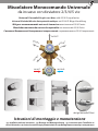
Miscelatore Monocomando Universale
da incasso con deviatore 2/3/4/5 vie
Universal Concealed Single Lever Mixer with 2/3/4/5 way diverter
Universal-Einhebel-Mischer Unterputzeinbaukörper mit 2/3/4/5-Wege-Umstellung
Mitigeur monocommande universel à encastrer avec inverseur 2/3/4/5 voies
Mezclador monomando universal empotrable con inversor de 2/3/4/5 vías
Смеситель Механический Универсальный встраиваемый 2/3/4/5
Istruzioni di montaggio e manutenzione
Installation and care instructions Montage-und Wartungsanleitung Instructions pour l’installation et
conseils d’entretien Instrucciones de montaje y de mantenimiento Инструкция по монтажу и эксплуатации
OUTLET
OUTLET
OUTLET
OUTLET
OUTLET
IN COLDIN HOT
design Marcello Ziliani

2.5
1
245
8
75
9
10 14
11
12 13
15 16
3
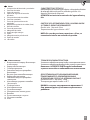
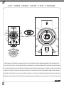
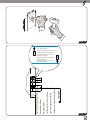
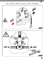
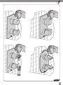
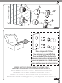
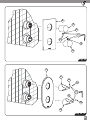
Le manopole 11 e 14 possono essere indierentemente tonde come qui mostrato, oppure quadre, in stile o sagomate come mostrato in copertina.
The knobs 11 and 14 can be indierently round (as hereby shown), square, classical or shaped as shown in the cover.
Die Grie 11 und 14 können unterschiedslos rund (als hier gezeigt), eckig, klassisch oder proliert wie auf dem Cover geformt sein.
Les poignées 11 et 14 peuvent être indiéremment ronds (comme illustré ici), carrés, classiques ou prolées comme indiqué dans la couverture.
Las perillas 11 y 14 pueden ser indistintamente redondas (como se muestra aquí), cuadradas, clásicas o perladas como se muestra en la cubierta.
11 14 , , , , .
6
10
2
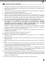
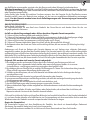
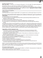
LEGGERE ATTENTAMENTE IL PRESENTE LIBRETTO DI INSTALLAZIONE E MANUTENZIONE.
READ THIS INSTALLATION AND CARE MANUAL CAREFULLY.
DIE VORLIEGENDE MONTAGE- UND WARTUNGSANLEITUNG AUFMERKSAM DURCHLESEN.
LIRE ATTENTIVEMENT CETTE NOTICE D’INSTALLATION ET D'ENTRETIEN.
LEA ATENTAMENTE ESTE MANUAL DE INSTALACIÓN Y MANTENIMIENTO.READ THIS
,
INDOSSARE I DISPOSITIVI DI PROTEZIONE INDIVIDUALI.
PUT ON INDIVIDUAL PROTECTION DEVICES.
INDIVIDUELLE SCHUTZGERÄTE ÜBERZIEHEN.
METTRE DES DISPOSITIFS DE PROTECTION INDIVIDUELS.
PONER DISPOSITIVOS DE PROTECCIÓN INDIVIDUAL.
.

3
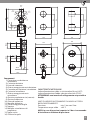
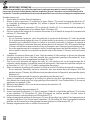
CARATTERISTICHE TECNICHE:
Indice alimentazione calda: a sinistra colore Rosso (HOT)
Indice alimentazione fredda: a destra colore blu (COLD)
ATTENZIONE: non invertire il collegamento acqua calda e
fredda.
LIMITI DI IMPIEGO RACCOMANDATI DA UNI EN 817 PER IL
BUON FUNZIONAMENTO
Pressione: min 1 bar max 5 bar
Temperatura acqua calda: ≤ 65°C
NOTA: in caso di pressioni superiori a 5 bar si raccomanda
di installare un riduttore di pressione.
120
100
210
14
Ø45Ø45
30-55
118.5
60
37
18.5
145
168
G 1/2"
OUT
G 1/2"
OUT
G 1/2"
OUT
G 1/2"
OUT
G 1/2"
OUT
G 1/2"
COLD
IN
G 1/2"
HOT
IN
100
130
230
100
120
210
100
210
120
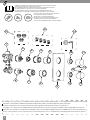
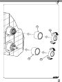
Componenti
1) Corpo incasso deviatore e
miscelatore
2) Cartuccia deviatore
3) Fermo di rotazione
4) Ghiera serraggio cartuccia deviatore
5) Cannotto per deviatore/ miscelatore
6) Cartuccia miscelatore
7) Ghiera serraggio cartuccia
miscelatore
8) Piastrina regolazione vie (camma)
9) Piastra di copertura
10) Ghiera di copertura
11) Maniglia deviatrice
12) Grano ssaggio maniglie
13) Tappino
14) Maniglia miscelatrice e di
erogazione
15) Tappo uscite
16) Chiave a brugola

4
TECHNICAL CHARACTERISTICS:
Hot water indicator: on the left in Red
Cold water indicator: to the right in Blue
CAUTION: do not invert the hot/cold water connections.
LIMITS RECOMMENDED BY UNI EN 817 FOR GOOD
FUNCTIONING
Min. Pressure 1 bar max. 5 bar
Hot water temp.: ≤ 65°C
NOTE: In case of pressures above 5 bar it is recommended
to install a pressure reducer.
TECHNISCHE EIGENSCHAFTEN:
Warmwasseranzeige: links rot
Kaltwasseranzeige: rechts blau
ACHTUNG: Warm- und Kaltwasseranschluss nicht
austauschen.
GRENZWERTE NACH UNI EN 817 (EUROPÄISCHE NORM) FÜR
EINE OPTIMALE BETRIEBSWEISE
Betriebsdruck: Min. 1 bar max. 5 bar
Warmwassertemperatur: ≤ 65°C
HINWEIS: Bei Wasser Drück mehr als 5 bar, wird es
empfohlen, einen Druckminderer zu installieren.
CARACTERISTIQUES TECHNIQUES:
Indicateur alimentation eau chaude : à gauche, couleur rouge
Indicateur alimentation eau froide : à droite, couleur bleue
ATTENTION : ne pas intervertir le raccordement de l’eau
chaude et de l’eau froide.
LIMITES D’UTILISATION RECOMMANDEES PAR LA NORME UNI
EN 817 POUR UN BON FONCTIONNEMENT
Pression : min. 1 bar, max. 5 bar
Température de l’eau chaude : ≤ 65°C
REMARQUE: En cas de pressions supérieures à 5 bar, il est
recommandé d'installer un réducteur de pression.
Components
1. Recessed diverter and mixer
2. Diverter cartridge
3. Rotation locking ring
4. Diverter cartridge tightening ring nut
5. Diverter/mixer sleeve
6. Mixer cartridge
7. Mixer cartridge lock nut
8. Ways-regulation plate (cam)
9. Cover plate
10. Cover ferrule
11. Diverter handle
12. Grub screw for xing handles
13. Cap
14. Mixing and on-o handle
15. Outow cap
16. Hex key
Bestandteile
1. Misch-/Umstellkartuschenfach
2. Umstellkartusche
3. Drehsperrering
4. Umstellkartuschen-Druckhülse
5. Umstell-/Mischrohr
6. Mischkartusche
7. Gewindering zur Befestigung der
Mischkartusche
8. Wege-Verstellungsplättchen (die Nocke)
9. Abdeckplatte
10. Abdeckhülse
11. Umstellerhebel
12. Stift zur Gribefestigung
13. Gristopfen
14. Mischen und Ein-Aus Hebel
15. Ausgangs-Verschlussstopfen
16. Sechskantschlüssel
Pièces
1. Corps mural pour inverseur et mitigeur
2. Cartouche d'inverseur
3. Arrêt de rotation
4. Bague de serrage de cartouche d'inverseur
5. Fourreau pour inverseur/mitigeur
6. Cartouche mitigeur
7. Ecrou de serrage cartouche mitigeur
8. Plaquette de réglage des voies (came)
9. Plaque de protection
10. Bague de recouvrement
11. Poignée de l’inverseur
12. Vis sans tête pour xation des poignées
13. Cache-vis
14. Poignée de mélange et distribution
15. Bouchon pour sorties
16. Clé Allen

5
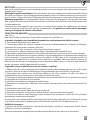
CARACTERÍSTICAS TÉCNICAS:
Indicación para la salida de agua caliente: a la izquierda, distintivo
de color rojo. Indicación para la salida de agua fría: a la
derecha, distintivo de color azul .
ATENCIÓN: no invierta las entradas del agua caliente y
fría.
LÍMITE DE USO RECOMENDADO POR LA NORMA UNI EN
817 PARA EL BUEN FUNCIONAMIENTO
Presión: mín. 1 bar máx. 5 bar
Temperatura del agua caliente: ≤ 65°C
NOTA: En caso de presiones superiores a 5 bar, se
recomienda instalar un reductor de presión.
ТЕХНИЧЕСКИЕ ХАРАКТЕРИСТИКИ:
:
:
Внимание: НЕ ПЕРЕПУТАЙТЕ трубы подведения
горячего и холодного водоснабжения к смесителю
ДЛЯ ОПТИМАЛЬНОГО ФУНКЦИОНИРОВАНИЯ,
ПРИДЕРЖИВАЙТЕСЬ РЕКОМЕНДОВАННЫХ
ОГРАНИЧЕНИЙ, СОГЛАСНО НОРМАМ: UNI EN 817
: . 1 . 5
: ≤ 65°C
ВАЖНО: в случае, когда давление превышает 5
бар, рекомендуется установить ограничитель
давления.
Piezas
1. Cuerpo oculto del desviador y mezclador
2. Cartucho desviador
3. Seguro de rotación
4. Cápsula de sujeción del cartucho
desviador
5. Tubo para desviador/mezclador
6. Cartucho mezclador
7. Tuerca de jación del cartucho
mezclador
8. Plaqueta de regulación de salidas (leva)
9. Placa de cubiertas
10. Tuerca de protecciónn
11. Mango del desviador
12. Grano para jar manijas
13. Tapón
14. Mango de mezcla y distribución
15. Tapón de vaciado
16. Llave Allen
Комплектация:
1.
2.
3.
4.
5. /
6.
7.
8.
()
9.
10.
11.
12.
13.
14.
15.
16.

6
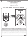
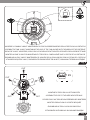
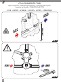
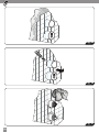
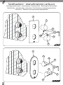
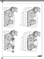
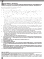
2 VIE - 2 WAYS - 2 WEGE - 2 VOIES 2 VÍAS 2
Fig_1
VERIFICARE LA POSIZIONE DELLE DUE FRECCE SULLA CARTUCCIA: DEVONO ESSERE ALLINEATE COME QUI MOSTRATO
CHECK THE POSITION OF THE TWO ARROWS ON THE CARTRIDGE: THE TWO ARROWS MUST BE ALIGNED LIKE HERE SHOWN
DIE STELLUNG DER ZWEI PFEILE AUF DER KARTUSCHE KONTROLLIEREN: DIE ZWEI PFEILE MÜSSEN WIE HIER GEZEIGT AUSGERICHTET WERDEN
VÉRIFIER LA POSITION DES DEUX FLÈCHES SUR LA CARTOUCHE: LES DEUX FLÈCHES DOIVENT ÊTRE ALIGNÉES COMME CIAPRÈS INDIQUÉ
VERIFICAR LA POSICIÓN DE LAS DOS FLECHAS SOBRE EL CARTUCHO: LAS DOS FLECHAS DEBEN ESTAR ALINEADAS COMO AQUÍ INDICADO
, ,
Congurazione miscelatore
Conguration of the mixer
Konguration des Mischers
Conguration du mitigeur
Conguración del mezclador

7
Fig_2
MONTARE LA CAMMA “2 WAYS“ MANTENENDO IL FORO IN CORRISPONDENZA DELLA FRECCIA SULLA CARTUCCIA
ASSEMBLE THE CAM “2 WAYS” MAINTAINING THE HOLE OF THE CAM ALIGNED WITH THE ARROW OF THE CARTRIDGE
DIE NOCKE “2 WAYS“ MONTIEREN, SO DASS DAS LOCH DER NOCKE MIT DEM PFEIL DER KARTUSCHE AUSGERICHTET WIRD
MONTER LA CAME “2 WAYS” EN MAINTENANT LE TROU DE LA CAME ALIGNÉE AVEC LA FLÈCHE DE LA CARTOUCHE
ENSAMBLAR LA LEVA “2 WAYS” MANTENIENDO EL AGUJERO DE LA LEVA ALINEADA CON LA FLECHA DEL CARTUCHO
“2 WAYS“, ,
OUT
OUT
Fig_3
X3
MONTARE I TAPPI SULLE USCITE INDICATE
ASSEMBLE THE CAPS TO THE HERE INDICATED WAYS
DIE VERSCHLÜSSE AUF DIE HIER ANGEGEBENEN WEGE MONTIEREN
MONTER LES BOUCHONS AUX SORTIES INDIQUÉES
ENSAMBLAR LAS TAPAS A LAS SALIDAS INDICADAS

8
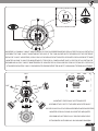
Fig_4
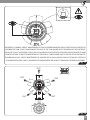
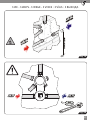
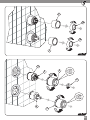
3 VIE 3 WAYS 3 WEGE 3VOIES 3 VÍAS 3
VERIFICARE LA POSIZIONE DELLE DUE FRECCE SULLA CARTUCCIA: DEVONO ESSERE ALLINEATE COME QUI MOSTRATO
CHECK THE POSITION OF THE TWO ARROWS ON THE CARTRIDGE: THE TWO ARROWS MUST BE ALIGNED LIKE HERE SHOWN
DIE STELLUNG DER ZWEI PFEILE AUF DER KARTUSCHE KONTROLLIEREN: DIE ZWEI PFEILE MÜSSEN WIE HIER GEZEIGT AUSGERICHTET WERDEN
VÉRIFIER LA POSITION DES DEUX FLÈCHES SUR LA CARTOUCHE: LES DEUX FLÈCHES DOIVENT ÊTRE ALIGNÉES COMME CIAPRÈS INDIQUÉ
VERIFICAR LA POSICIÓN DE LAS DOS FLECHAS SOBRE EL CARTUCHO: LAS DOS FLECHAS DEBEN ESTAR ALINEADAS COMO AQUÍ INDICADO
, ,

9
Fig_5
OUT
OUT
OUT
Fig_6
X2
MONTARE LA CAMMA “3 WAYS“ MANTENENDO IL FORO IN CORRISPONDENZA DELLA FRECCIA SULLA CARTUCCIA
ASSEMBLE THE CAM “3 WAYS” MAINTAINING THE HOLE OF THE CAM ALIGNED WITH THE ARROW OF THE CARTRIDGE
DIE NOCKE “3 WAYS“ MONTIEREN, SO DASS DAS LOCH DER NOCKE MIT DEM PFEIL DER KARTUSCHE AUSGERICHTET WIRD
MONTER LA CAME “3 WAYS” EN MAINTENANT LE TROU DE LA CAME ALIGNÉE AVEC LA FLÈCHE DE LA CARTOUCHE
ENSAMBLAR LA LEVA “3 WAYS” MANTENIENDO EL AGUJERO DE LA LEVA ALINEADA CON LA FLECHA DEL CARTUCHO
“3 WAYS“, ,
MONTARE I TAPPI SULLE USCITE INDICATE
ASSEMBLE THE CAPS TO THE HERE INDICATED WAYS
DIE VERSCHLÜSSE AUF DIE HIER ANGEGEBENEN WEGE MONTIEREN
MONTER LES BOUCHONS AUX SORTIES INDIQUÉES
ENSAMBLAR LAS TAPAS A LAS SALIDAS INDICADAS

10
Fig_7
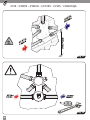
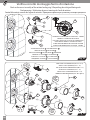
4 VIE 4 WAYS - 4 WEGE - 4 VOIES 4 VÍAS 4
VERIFICARE LA POSIZIONE DELLE DUE FRECCE SULLA CARTUCCIA: DEVONO ESSERE ALLINEATE COME QUI MOSTRATO
CHECK THE POSITION OF THE TWO ARROWS ON THE CARTRIDGE: THE TWO ARROWS MUST BE ALIGNED LIKE HERE SHOWN
DIE STELLUNG DER ZWEI PFEILE AUF DER KARTUSCHE KONTROLLIEREN: DIE ZWEI PFEILE MÜSSEN WIE HIER GEZEIGT AUSGERICHTET WERDEN
VÉRIFIER LA POSITION DES DEUX FLÈCHES SUR LA CARTOUCHE: LES DEUX FLÈCHES DOIVENT ÊTRE ALIGNÉES COMME CIAPRÈS INDIQUÉ
VERIFICAR LA POSICIÓN DE LAS DOS FLECHAS SOBRE EL CARTUCHO: LAS DOS FLECHAS DEBEN ESTAR ALINEADAS COMO AQUÍ INDICADO
, ,

11
Fig_8
OUT
OUT
OUT OUT
Fig_9
X1
MONTARE LA CAMMA “4 WAYS“ MANTENENDO IL FORO IN CORRISPONDENZA DELLA FRECCIA SULLA CARTUCCIA
ASSEMBLE THE CAM “4 WAYS” MAINTAINING THE HOLE OF THE CAM ALIGNED WITH THE ARROW OF THE CARTRIDGE
DIE NOCKE “4 WAYS“ MONTIEREN, SO DASS DAS LOCH DER NOCKE MIT DEM PFEIL DER KARTUSCHE AUSGERICHTET WIRD
MONTER LA CAME “4 WAYS” EN MAINTENANT LE TROU DE LA CAME ALIGNÉE AVEC LA FLÈCHE DE LA CARTOUCHE
ENSAMBLAR LA LEVA “4 WAYS” MANTENIENDO EL AGUJERO DE LA LEVA ALINEADA CON LA FLECHA DEL CARTUCHO
“4 WAYS“, ,
MONTARE IL TAPPO SULLA USCITA INDICATA
ASSEMBLE THE CAP TO THE HERE INDICATED WAY
DIE VERSCHLUSS AUF DEN HIER ANGEGEBENEN WEG MONTIEREN
MONTER LE BOUCHON À LA SORTIE INDIQUÉE
ENSAMBLAR LA TAPA A LA SALIDA INDICADA

12
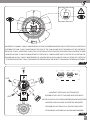
Fig_10
5 VIE 5 WAYS - 5 WEGE - 5 VOIES 5 VÍAS 5
VERIFICARE LA POSIZIONE DELLE DUE FRECCE SULLA CARTUCCIA: DEVONO ESSERE ALLINEATE COME QUI MOSTRATO
CHECK THE POSITION OF THE TWO ARROWS ON THE CARTRIDGE: THE TWO ARROWS MUST BE ALIGNED LIKE HERE SHOWN
DIE STELLUNG DER ZWEI PFEILE AUF DER KARTUSCHE KONTROLLIEREN: DIE ZWEI PFEILE MÜSSEN WIE HIER GEZEIGT AUSGERICHTET WERDEN
VÉRIFIER LA POSITION DES DEUX FLÈCHES SUR LA CARTOUCHE: LES DEUX FLÈCHES DOIVENT ÊTRE ALIGNÉES COMME CIAPRÈS INDIQUÉ
VERIFICAR LA POSICIÓN DE LAS DOS FLECHAS SOBRE EL CARTUCHO: LAS DOS FLECHAS DEBEN ESTAR ALINEADAS COMO AQUÍ INDICADO
, ,

13
Fig_11
OUT
OUT
OUT OUT
OUT
Fig_12
MONTARE LA CAMMA “5 WAYS“ MANTENENDO IL FORO IN CORRISPONDENZA DELLA FRECCIA SULLA CARTUCCIA
ASSEMBLE THE CAM “5 WAYS” MAINTAINING THE HOLE OF THE CAM ALIGNED WITH THE ARROW OF THE CARTRIDGE
DIE NOCKE “5 WAYS“ MONTIEREN, SO DASS DAS LOCH DER NOCKE MIT DEM PFEIL DER KARTUSCHE AUSGERICHTET WIRD
MONTER LA CAME “5 WAYS” EN MAINTENANT LE TROU DE LA CAME ALIGNÉE AVEC LA FLÈCHE DE LA CARTOUCHE
ENSAMBLAR LA LEVA “5 WAYS” MANTENIENDO EL AGUJERO DE LA LEVA ALINEADA CON LA FLECHA DEL CARTUCHO
“5 WAYS“, ,

Fig_13
Fig_14
SALVO DOVE DIVERSAMENTE SPECIFICATO, LE ILLUSTRAZIONI MOSTRANO IL MISCELATORE CONFIGURATO A 5 VIE
UNLESS DIFFERENTLY SPECIFIED, THE PICTURES SHOW THE 5-OUTLETS MIXER SET-UP
AUSGENOMMEN ANDERS BESTIMMT, ZEIGEN DIE ABBILDUNGEN DIE 5-AUSGÄNGE EINSTELLUNG
SAUF INDICATION CONTRAIRE, LES IMAGES MONTRENT LA CONFIGURATION DU MITIGEUR A 5 SORTIES
A MENOS QUE SE ESPECIFIQUE LO CONTRARIO, LAS IMÁGENES MUESTRAN LA CONFIGURACIÓN DEL MEZCLADOR DE 5 SALIDAS
, 5
14
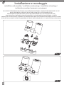
Installazione e montaggio
installation and assembly / installation und montage / installation et montage /
instalación y montaje /

Fig_15
Fig_16
15
1 0 1957
52 0 350
53 78
1100 1200
MAX
MIN
- Limite de tolerance pour la surface
exterieure du carrelage
- Limiti di tolleranza per la superficie
finita delle piastrelle
- Adjustm ent limits for nished tiles surfaces
- Toleranzgrenze der iesenoberache
- Límites de tolerancia para la supercie
acabada del azulejo
- Пределы допуска для поверхности
с финишной отделкой
supercie nita delle piastrelle
nished tiles surfaces
iesenoberache
surface exterieure du carrelage
supercie acabada del azulejo
поверхности с финишной отделкой

Fig_17
UA
ACQ
DD
FRE A
C UA Q A
ALD
CA
1100 1200
Fig_18
C UA Q A
ALD
CA
UA
ACQ
DD
FRE A
16
2 VIE - 2 WAYS - 2 WEGE - 2 VOIES 2 VÍAS 2
COLLEGAMENTO TUBI
Pipes connection / Verbindung der Rohren / Connexion des tuyaux /
Conexión de tuberiás /

Fig_19
UA
ACQ
DD
FRE A
C UA Q A
ALD
CA
1100 1200
Fig_20
C UA Q A
ALD
CA
UA
ACQ
DD
FRE A
17
3 VIE - 3 WAYS - 3 WEGE - 3 VOIES 3 VÍAS 3

Fig_21
UA
ACQ
DD
FRE A
C UA Q A
ALD
CA
1100 1200
Fig_22
C UA Q A
ALD
CA
UA
ACQ
DD
FRE A
18
4 VIE - 4 WAYS - 4 WEGE - 4 VOIES 4 VÍAS 4

Fig_23
UA
ACQ
DD
FRE A
C UA Q A
ALD
CA
1100 1200
Fig_24
C UA Q A
ALD
CA
UA
ACQ
DD
FRE A
5 VIE - 5 WAYS - 5 WEGE - 5 VOIES 5 VÍAS 5
19

Fig_23
Fig_25
Fig_23
Fig_26
Fig_23
Fig_27
20

Fig_23
Fig_28
5
10
510
21

9
11
12
13
14
2.5
12
9
11
14
12
13
13
Fig_29
2.5
Fig_29_A
22

Fig_23
Fig_30
23

24
INSTALLAZIONE E MONTAGGIO
1. Configurare il miscelatore monocomando in base alle vie (uscite) desiderate (fig. da 1 a 12)
2. Fissare la protezione in polistirolo superiore e quella inferiore con del nastro adesivo
(fig. 13 e 14)
3. Creare nel muro lo spazio necessario per l’alloggiamento del miscelatore completo con la
protezione in polistirolo. (fig. 15)
4. Rispettare le quote riportate in figura 16.
5. Alloggiare i tubi idraulici per l’alimentazione dell’acqua fredda nella parte inferiore destra
e dell’acqua calda nella parte inferiore sinistra. Nella parte superiore, alloggiare i tubi
idraulici per l’erogazione ai servizi secondo la configurazione. (fig. 17/19/21/23) (deviatore).
6. Per evitare che impurità o detriti possano giungere all’interno del miscelatore dando
origine a problemi di funzionamento, spurgare l’impianto prima di collegare i tubi di
alimentazione. É consigliabile installare all’ingresso dell’impianto un apposito filtro.
7. Sistemare il miscelatore monocomando completo con la protezione in polistirolo facendo
attenzione che la superfice del muro finito (con piastrelle) rientri nella tolleranza indicata
(min 53 mm, max 78 mm). (fig 16)
8. Completare i collegamenti come illustrato in figure 18/20/22/24, secondo la configurazione.
9. Testare l'impianto e verificare l'assenza di perdite.
10. Eseguire il rivestimento, vedi figura 25.
11. Ritagliare la protezione in polistirolo di copertura a filo piastrelle. (fig. 26)
12. Rimuovere eventuale sporco e/o impurità presenti sulle superfici del miscelatore e delle
piastrelle. (fig. 27)
13. Montare i due cannotti (5) ed avvitare le due ghiere di copertura (10). (fig. 28)
14. Rimuovere pellicola dalla spugna nella parte posteriore della piastra di copertura (9).
Inserire la piastra sui due cannotti sporgenti della parte incasso del rubinetto e spingerla
contro la parete (fig. 29 - fig. 29_A)
15. Inserire la maniglia deviatrice (11). Fissarla con l’apposito grano (12) ed inserire tappino
(13) (fig. 29). Per la maniglia in versione sagomata, rispettare l'orientamento indicato in
fig. 29_A.
16. Inserire la maniglia miscelatrice e di erogazione (14) tenendo il foro rivolto verso l'alto
come illustrato in figura 29. Fissarla con l’apposito grano (12) ed inserire tappino (13). Per
la maniglia in versione sagomata, rispettare l'orientamento indicato in fig. 29_A.
17. Pulire accuratamente i prodotti montati (Fig. 30).

25
INSTALLATION AND ASSEMBLY
1. Set up the single lever mixer according to the required ways (Fig. 1-12)
2. Fix the upper and lower protective polystyrene covers in place using adhesive tape (Fig. 13
and 14).
3. Create enough space in the wall to fit the mixer including polystyrene protective casing (Fig.
15).
4. Ensure compliance with the limits indicated in Figure 16.
5. Organise the cold water supply pipes in the lower right hand side and the hot water pipes in
the lower left. In the upper part, house the sanitary pipes for water supply according to the
mixer set-up (pictures 17/19/21/23) (diverter).
6. To prevent impurities or debris from entering the mixer and causing operating
problems, flush out the system before connecting the supply pipers. The
installation of a special inflow filter is recommended.
7. Mount the single lever mixer including polystyrene protective casing, ensuring that the
surface of the finished wall (including tiles) falls within the indicated clearance limits (min 53
mm, max 78 mm). (Fig 16).
8. Complete the connections as shown in pictures 18/20/22/24, according to the mixer set-up.
9. Check the plant and verify the absence of any leak
10. Clad the walls, see Fig. 25.
11. Cut away the polystyrene protection to the edge of the tiles (Fig. 26).
12. Remove any dirt and/or impurities found on the surface of the mixer and tiles (Fig. 27).
13. Assemble the two bushes (5) and screw the two cover rings (10). (Fig. 28)
14. Remove the film from the sponge in the posterior part of the cover plate (9). Insert the cover
plate on the headworks of the concealed part of the mixer and then push it against the wall
(fig. 29 - fig. 29_A)
15. Mount the diverter knob (11). Fix it in place with the grub screw (12) and insert the cap (13)
(Fig. 29). For the handle in shaped version, the positioning as shown in fig. 29_A must be
followed.
16. Insert the mixing and dispensing handle (14) by holding the hole facing up as shown in Figure
29. Attach it with the special grain (12) and insert the cap (13). For the handle in shaped
version, the positioning as shown in fig. 29_A must be followed.
17. Clean the mounted components with care (Fig. 30).

26
INSTALLATION UND MONTAGE
1. Den Einhebel Mischer gemäß den erforderlichen Wege aufstellen (Abb. 1-12)
2. Den oberen und unteren Polystyrol-Schutz mit Klebeband befestigen. (Abb. 13 und 14)
3. In der Wand genug Platz für die Unterbringung des Ein-Hebel Mischers samt Polystyrol-
Schutz schaffen. ( Abb. 15)
4. Die in Abbildung 16 dargestellte Höhe einhalten.
5. Den Kaltwasseranschluss unten rechts und den Warmwasseranschluss unten links
unterbringen. Im oberen Teil die Sanitärrohre für die Wasserversorgung nach der
Mischereinstellung einsetzen (Abbildungen 17/19/21/23) (Umsteller).
6. Um zu verhindern, dass Schmutz oder Ablagerungen in den Mischer gelangen
und zu Funktionsstörungen führen, muss die Rohrleitung vor dem Anschluss
sorgfältig gespült werden. Das Einbauen eines Filters am Eingang der Anlage
ist zu empfehlen.
7. Den Ein-Hebel Mischer mit Polystyrol-Schutz einsetzen, dabei darauf achten, dass die
Oberfläche der gefliesten Wand im angegebenen Bereich liegt (min. 53 mm, max. 78
mm). (Abb. 16)
8. Die Anschlüsse, wie in den Abbildungen 18/20/22/24 gezeichnet und nach der
Mischereinstellung, vervollständigen.
9. Die Anlage testen und Dichtheit überprüfen
10. Verputzen, siehe Abbbildung 25.
11. Den Polystyrol-Abdeckschutz mit den Fliesen abschließend wegschneiden (Abb. 26).
12. Eventuelle Verschmutzungen an der Oberfläche des Ein-Hebel Mischers und an den
Fliesen entfernen. (Abb. 27)
13. Die zwei Buchsen (5) montieren und die zwei Deckungsringe (10) einschrauben. (Abb.
28)
14. Die Folie hinten der Abdeckplatte (9) vom Schwamm entfernen. Die Abdeckplatte
auf den Oberteilen des Unterputz-Teils der Brausebatterie durchziehen und dann sie
gegen die Wand drucken (Abb. 29 - Abb. 29_A).
15. Bauen Sie den Umstellergriff (11) ein. Befestigen Sie ihn mit dem geeigneten Stift
(12) und bauen Sie den Griffstopfen (13) ein (Abb. 29). Für den Griff in profilierter
Ausführung, muss man die Richtung wie im Bild 29_A gezeigt folgen.
16. Den Mischen und aus-zu Hebel (14) einstecken und das Loch nach oben halten, wie in
Abbildung 29 gezeigt. Mit dem Sondergewindestift (12) ihn befestigen und den Deckel
(13) einsetzen. Für den Griff in profilierter Ausführung, muss man die Richtung wie im
Bild 29_A gezeigt folgen.
17. Die montierten Produkte sorgfältig reinigen. (Abb. 30)

27
INSTALLATION ET MONTAGE
1. Configurer le mitigeur monocommande selon les voies demandées (illustrations 1-12)
2. Fixer la protection supérieure en polystyrène et celle inférieure avec du ruban adhésif
(illustrations 13 et 14).
3. Creuser dans le mur un emplacement suffisamment grand pour y placer le mitigeur et
sa protection en polystyrène (illustration 15).
4. Veuillez respecter les mesures indiquées sur l’illustration 16.
5. Loger les tuyaux hydrauliques pour l’alimentation en eau froide dans la partie
inférieure droite et ceux pour l’alimentation en eau chaude dans la partie inférieure
gauche. Dans la partie supérieure, placer les tuyaux sanitaires pour l'alimentation en
eau selon la configuration du mitigeur (illustrations 17/19/21/23) (inverseur).
6. Pour éviter que des impuretés ou des saletés ne s’introduisent à l’intérieur
du mitigeur et n’entraînent des problèmes de fonctionnement, vidanger
l’installation avant de raccorder les tuyaux d’alimentation. Il est conseillé
d’installer, à l’entrée de l’installation, un filtre prévu à cet effet.
7. Installer le mitigeur monocommande avec sa protection en polystyrène en faisant
attention à ce que la surface du mur fini (avec carrelage) rentre dans la tolérance
indiquée (min 53 mm, max 78 mm) (illustration 16).
8. Compléter les raccordements selon les illustrations 18/20/22/24, en fonction de la
configuration du mitigeur.
9. Contrôler l’installation et vérifier l'absence de toute fuite
10. Réaliser le revêtement comme sur l’illustration 25.
11. Découper la protection de recouvrement en polystyrène au ras du carrelage.
(illustration 26)
12. Éliminer les éventuelles saletés et/ou impuretés présentes sur le mitigeur et le carrelage.
(illustration 27)
13. Monter les deux douilles (5) et visser les deux anneaux de couverture (10). (illustration
28)
14. Enlever le film de l'éponge dans la partie postérieure de la plaque de couverture (9).
Insérer la plaque sur les deux têtes de la partie encastrée du mitigeur, et puis pousser la
plaque contre le mur (illustration 29 - illustration 29_A)
15. Insérer la poignée de l’inverseur (11). La fixer à l’aide de la vis appropriée (12) puis
insérer le cache-vis (13) (illustration 29). Pour la poignée en version profilée, on doit
suivre le positionnement comme indiqué sur l’illustration 29_A.
16. Insérer la poignée de mélange et de distribution (14) en maintenant le trou vers le haut
comme indiqué sur la figure 29. Fixer-la avec le grain spécial (12) et insérer le bouchon
(13). Pour la poignée en version profilée, on doit suivre le positionnement comme
indiqué sur l’illustration 29_A.
17. Une fois montés, nettoyer soigneusement les produits. (illustration 30).

28
INSTALACIÓN Y MONTAJE
1. Configurar el mezclador monomando de acuerdo con las salidas requeridas (fig. 1-12)
2. Fije la protección de poliestireno superior e inferior con la cinta adhesiva (fig. 13 y 14).
3. Cree el espacio suficiente en la pared para instalar el mezclador provisto de la
protección de poliestireno. (fig. 15).
4. Respete las medidas que se muestren en la figura 16.
5. Instale los tubos hidráulicos para la alimentación del agua fría en la parte inferior
derecha y del agua caliente, en la parte inferior izquierda. En la parte superior, poner
las tuberías sanitarias para el suministro de agua de acuerdo con la configuración del
mezclador (ilustraciones 17/19/21/23) (desviador).
6. Para evitar que impurezas o residuos lleguen al interior del mezclador,
provocando problemas de funcionamiento, purgue la instalación antes de
conectar los tubos de alimentación. Se recomienda instalar un filtro adecuado
en la entrada de la instalación.
7. Coloque el mezclador monomando provisto de la protección de poliestireno,
prestando atención para que la superficie de la pared acabada (con azulejos) se ajuste
a las siguientes medidas: mín. 53 mm, máx. 78 mm. (fig. 16).
8. Completar las conexiones según las ilustraciónes 18/20/22/24, de acuerdo con la
configuración del mezclador.
9. Revisar la instalación y verificar la ausencia de cualquier pérdida
10. Realice el revestimiento, véase figura 25.
11. Corte la protección de poliestireno de cobertura al mismo nivel que los azulejos (fig.
26).
12. Elimine la posible suciedad y/o impurezas presentes en la superficie del mezclador y
en los azulejos (fig. 27).
13. Montar los dos casquillos (5) y atornillar los dos anillos de cubierta (10). (fig. 28)
14. Remover la película de la esponja en la parte posterior de la placa de cubierta (9).
Insertar la placa de cubierta en las monturas de la parte de emportado del mezclador
y empujarla contra la pared (fig. 29 - fig. 29_A)
15. Introduzca la manilla desviadora (11). Fíjela con el bulón correspondiente (12) e
introduzca el tapón (13) (fig. 29). Para la maneja en versión perfilada, debe seguirse el
posicionamiento como se muestra en la fig. 29_A
16. Insertar el mango de mezcla y distribución (14) manteniendo el agujero hacia arriba
como se muestra en la figura 29. Fijarlo con el grano especial (12) e insertar la tapa
(13). Para la maneja en versión perfilada, debe seguirse el posicionamiento como se
muestra en la fig. 29_A
17. Limpie minuciosamente los productos montado (fig. 30).

29
РАБОТЫ ПО МОНТАЖУ И УСТАНОВКЕ
1. ,
() (. 1 12)
2.
(. 13 14).
3. ,
. (. 15)
4. , . 16.
5.
.
.
(. 17/19/21/23) ().
6. Во избежание загрязнения и попадания мусора во внутрь смесителя,
которые могут привести к проблемам функционирования, выпустить
воду из труб, до подключения их к устройству. Рекомендуется
установить соответствующие фильтры на входе к смесителю.
7. ,
, ,
(. 53 , . 78 ). (.16)
8. ,
18/20/22/24, .
9. .
10. , . . 25.
11. (. 26).
12.
(. 27).
13. (5) (10). (. 28).
14. ,
(9). ,
(. 29 - . 29_A).
15. (11). (12)
(13) (. 29). ,
, . 29 .
16. (14) ,
, 29.
(12) (13). ,
, . 29 .
17. , (. 30).

2.5
11
14
13 12
12
2.5
30
Fig_31
9
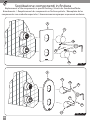
Sostituzione componenti in nitura
Replacement of the components in special nishing / Ersatz der Sonderoberäche-
Bauelemente / Remplacement des composants en nition spéciale / Reemplazo de los
componentes con acabados especiales /
11
14
13
12
12
9
Fig_31_A
13

Fig_33
Nuovi componenti in nitura
New components in special nishing
Neue Sonderoberäche-Bauelemente
Nouveaux composants en nition spéciale
Nuoevos componentes con acabado especial
RIPETERE A RITROSO I PASSAGGI INDICATI IN FIGURE 32 E 31
REPEAT BACKWARDS THE STEPS SHOWN IN FIGURES 32 AND 31
DIE SCHRITTE IN DEN BILDER 32 UND 31 RÜCKWÄRTS WIEDERHOLEN
RÉPÉTER EN SENS INVERSE LES ÉTAPES DES FIGURES 32 ET 31
REPETIR HACIA ATRÁS LOS PASOS MOSTRADOS EN LAS FIGURAS 32 Y 31
, 32 31
31
Fig_32
5
10
10
5

Sostituzione - manutenzione cartucce
Cartridge replacement - maintenance / Auswechseln - Wartung der Kartuschen
Substitution - entretien des cartouches / Sustitución y mantenimiento de los
cartuchos /
32
2.5
11
14
13 12
12
Fig_34
9
2.5
11
14
13
12
12
9
Fig_34_A
13

Fig_36
35
35
2
4
8
7
6
3
33
Fig_35
5
5
10
10

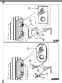
Verica corretto montaggio fermo di rotazione
Check on the correct assembly of the rotation locking ring / Überprüfung der richtigen Montage des
Drehsperrerings / Vérication du correct montage de l’arrêt de rotation
Control del montaje correcto del seguro de rotación /
ACCOPPIARE SPACCO A CON NERVATURA B
JOIN THE RECESS A TO THE RIB B
DIE AUSSPARUNG A MIT DER RIPPE B VERBINDEN
COUPLER LA CAVITÉ A À LA NERVURE B
ACOPLAR LA CAVIDAD A A LA NERVURA B
CORRETTO ACCOPPIAMENTO CARTUCCIA - FERMO
CORRECT CARTRIDGELOCK JOINT
RICHTIGE KARTUSCHEFESTSTELLERVERBINDUNG
COUPLEMENT CORRECT CARTOUCHEARRÊT
ACOPLAMENTO CORRECTO CARTUCHOSEGURO
2
Fig_37
3
3
3
A
A
B
B
2
35
35
12 Nm
12 Nm
8
5
2
4
Fig_38
VERIFICARE ALLINEAMENTO (FIG. DA 1 A 12)
VERIFY THE ALIGNMENT FIG. 112
DIE AUSRICHTUNG ÜBERPRÜFEN ABB. 112
VÉRIFIER L’ALIGNEMENT FIG. 112
VERIFICAR EL ALINEAMENTO FIG. 112
(. 1 12)
5
10
67
10
6
2
3
34

2.5
Fig_39
9
11
13
14
12
12
35
2.5
11
14
13
12
12
9
Fig_39_A
13

Fig_40
36

37
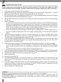
MANUTENZIONE E RIPARAZIONE
Premessa: L’uso continuo e prolungato nel tempo e le caratteristiche dell’acqua
erogata dalla rete idrica (calcare / impurità), possono causare una perdita di efficienza
della cartuccia. Pertanto può rendersi necessaria la sua manutenzione e pulizia o la
sostituzione.
Procedere come segue:
1. Chiudere tutte le alimentazioni idrauliche che forniscono acqua al miscelatore.
2. Rimuovere i tappini (13) e svitare i grani (12); sfilare la maniglia deviatrice (11), la maniglia
miscelatrice e di erogazione (14); togliere anche la piastra di copertura (9). (fig. 34 - fig.
34_A)
3. Svitare le ghiere di copertura (10) e sfilare i cannotti (5). È consigliabile proteggere il
contatto tra la chiave operatrice e le ghiere. (fig. 35)
4. Svitare la ghiera di serraggio cartuccia deviatore (4) e la ghiera di serraggio cartuccia
miscelatore (7). (fig. 36)
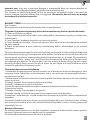
5. Cartuccia deviatore:
• nel caso di sola manutenzione slare il gruppo cartuccia deviatore (2), fermo di ro-
tazione (3), e piastrina di regolazione vie (8); per favorire il successivo inserimento con-
sigliamo di slare mantenendo tutto il gruppo assemblato. Togliere eventuali residui
o incrostazioni formatisi nell' alloggiamento della cartuccia. Immergere le cartucce in
acqua e aceto (50% + 50%) per 12 ore circa, favorendo in questo modo l'eliminazione
di calcare ed eventuali impurità, poi procedere dal punto n°6;
• nel caso si voglia sostituire la cartuccia con una nuova, verificare il corretto montaggio
del fermo di rotazione (3), esso deve essere assemblato e orientato sulla nuova cartuccia
come mostrato in fig. 37. Procedere dal punto n°6;
6. Inserire la cartuccia deviatore (2) con assemblato il fermo di rotazione (3), prestando molta
attenzione al piolo sporgente dalla sua base; esso deve entrare nella apposita sede (fig.
38). Avvitare la ghiera (4) e serrare applicando una coppia di 12 Nm.
7. Nel caso in cui la piastrina di regolazione vie (8) sia stata smontata, o nel caso di
sostituzione cartuccia con una nuova, verificare il corretto montaggio della piastrina; essa
deve rispettare l'orientamento indicato nelle fig. 1-2 / 4-5 / 7-8 / 10-11 a seconda della
configurazione.
8. Sfilare la cartuccia miscelatore (6) e togliere eventuali residui o incrostazioni formatisi nel
proprio alloggiamento:
• nel caso di sola manutenzione immergere le cartucce in acqua e aceto (50% + 50%) per
12 ore circa, favorendo in questo modo l'eliminazione di calcare ed eventuali impurità,
poi procedere dal punto n°9;
• nel caso si voglia sostituire la cartuccia con una nuova procedere dal punto n°9;
9. Inserire la cartuccia miscelatore (6); prestando molta attenzione ai due pioli sporgenti dalla
sua base; essi devono entrare nella apposita sede (fig. 38). Avvitare la ghiera (7) e serrare
applicando una coppia di 12 Nm.
10. Montare i due cannotti (5) ed avvitare le due ghiere di copertura (10).
11. Riaprire l'alimentazione acqua.
12. Posizionare la piastra di copertura (9).
13. Inserire la maniglia deviatrice (11). Fissarla con l’apposito grano (12) ed inserire tappino
(13). (fig. 39). Per la maniglia in versione sagomata, rispettare l'orientamento indicato in
fig. 39_A.
14. Inserire la maniglia miscelatrice e di erogazione (14) con il foro rivolto verso l'alto. Fissarla
con l’apposito grano (12) ed inserire tappino (13) (fig. 39). Per la maniglia in versione
sagomata, rispettare l'orientamento indicato in fig. 39_A.
15. Con un panno eseguire una accurata pulizia. (fig. 40)

38
PER LA PULIZIA
Per conservare il più a lungo possibile l’aspetto del materiale, è necessario osservare alcune
regole.
Per la pulizia parti metalliche: l’acqua contiene calcio che si deposita sulla superficie dei
prodotti e forma macchie sgradevoli. Per la normale pulizia del prodotto è sufficiente utilizzare
un panno umido con un po’ di sapone, sciacquare ed asciugare. E’ possibile quindi evitare la
formazione di macchie di calcare asciugandolo dopo ogni uso.
Nota importante: si consiglia di usare solamente detergenti a base di sapone. Non impiegare
mai detergenti o disinfettanti abrasivi o contenenti alcool, acido cloridrico o acido fosforico.
Caro cliente, le ricordiamo che la garanzia dei nostri prodotti non è valida se il materiale ha
subito un trattamento diverso da quello specificatamente indicato nelle presenti istruzioni.
La garanzia non copre danni causati da deposito di calcare o impurità.
CONDIZIONI DI GARANZIA
Gentile Cliente,
Ci complimentiamo con lei per aver scelto un prodotto Bossini e la ringraziamo per la fiducia
accordataci.
Il prodotto è garantito contro vizi o difetti di fabbricazione secondo quanto specificato
di seguito:
1) 5 anni per difetti di fusione o porosità;
2) 2 anni per difetti di cromatura (ad esclusione di difetti provocati da deterioramento per uso
di detersivi acidi o abrasivi)
3) 2 anni per cartucce (escluse guarnizioni e tenute)
4) 2 anni per elementi termostatici (la cui usura dipende dalla qualità dell’acqua)
5) La riparazione o la sostituzione di pezzi con difetti di fabbricazione, riconosciuti dal nostro
ufficio tecnico.
Le richieste di sostituzione in garanzia potranno essere avanzate solo presentando un
documento datato comprovante l’acquisto del prodotto. La garanzia si riferisce unicamente ai
difetti di fabbricazione e dà diritto esclusivamente alla fornitura gratuita del pezzo riconosciuto
difettoso. Il pezzo difettoso dovrà essere restituito a Bossini in porto franco, accompagnato
da un rapporto di descrizione del difetto. Bossini si riserva il diritto di ispezionare il pezzo
contestato per valutare l’applicabilità della garanzia.
La garanzia non copre i seguenti casi:
1- Deterioramento delle superfici cromate dovuto all`uso di prodotti per la pulizia contenenti
acidi o sostanze abrasive o comunque eseguita diversamente da quanto specificato nelle
nostre istruzioni di manutenzione e pulizia.
2- Deterioramento delle superfici con finiture diverse da quelle cromate. La loro durata è infatti
subordinata alla cura e alla delicatezza d`uso da parte dell’utente;
3- Danni alla rubinetteria imputabili ad installazione non corretta o ad errata concezione

39
dell’impianto;
4- Non corretto utilizzo della rubinetteria / Uso improprio della rubinetteria
5- Riparazioni e manutenzioni effettuate in modo non idoneo e senza preventiva autorizzazione
dell`Azienda;
6- Deterioramento dovuto alla normale usura;
7- Danni causati da deposito di calcare o impurità
8- Danni accidentali o conseguenti a smarrimenti e/o mancato utilizzo del prodotto
9- Costi di manodopera e/o danni, anche accidentali o conseguenti, occorsi durante
l’installazione, riparazione o sostituzione del prodotto.
Inoltre, se una volta accertato il guasto si renda necessario l’intervento a domicilio (su esplicita
richiesta del cliente), sono a carico del cliente tutti i costi di manodopera relativi ad eventuale
disintallazione e ripristino del prodotto, così come i relativi costi di trasferta
Decorrenza della garanzia:
La garanzia decorre dalla data di acquisto del prodotto, comprovata da documentazione
riscontrabile (fattura, scontrino fiscale) e non è rinnovabile.
Per ulteriori informazioni potete contattare Bossini o il rivenditore di zona.

40
MAINTENANCE AND REPAIRS
Premise: Continuous and extended use over time and the properties of the local water supply may lead to
a loss of efficiency of the cartridge. Therefore, maintenance, cleaning or replacement may be necessary.
1. Close every water inlet connections to the mixer.
2. Remove the small caps (13) and unscrew the threaded pins (12); extract the diverting handle (11) and the
diverting-mixing handle (14); remove the cover plate (9). (Fig. 34 - Fig. 34_A)
3. Unscrew the cover rings (10) and pull out the bushes (5). It is recommended to protect the contact between
the operating wrench and the threaded rings. (fig. 35)
4. Unscrew the clamping bush of the diverter cartridge (4) and the clamping bush of the mixing cartridge
(7). (fig. 36)
5. Diverter cartridge
• In case of sole maintenance, pull out the diverting cartridge assembly (2), the rotation locking ring (3),
and the ways-regulation plate (8); in order to ease the re-insertion, it is recommended also to pull out
the whole assembly without disassembling. Remove possible dirty and scale inside the seat of the car-
tridge. Put the cartridges in a 50%-50% water-vinegar solution for about 12 hours in order to remove
every trace of limestone and impurities, then proceed starting from point no. 6.
• In case of replacement of the cartridge, verify the right assembling of the rotation locking ring (3): it
must be assembled and oriented on the new cartridge according to fig. 37. Then proceed starting form
point 6.
6. Insert the diverting cartridge (2) with the rotation locking ring (3) already assembled, paying great
attention to the pin sticking out of the base: it must be entered into its specific seat (fig. 38). Screw the
threaded ring (4) and clamp applying a couple of 12 Nm.
7. In case the ways-regulation plate (8) has been removed or in case of replacement of the cartridge, always
verify the right assembling of the plate. It must respect the position shown in fig. 1-2 / 4-5 / 7-8 / 10-11
according to the set-up of the mixer.
8. Pull out the mixing cartridge (6) and remove possible dirty and scale inside the seat of the cartridge:
• in case of sole maintenance, put the cartridges in a 50%-50% water-vinegar solution for about 12
hours in order to remove every trace of limestone and impurities, then proceed starting from point
no. 9
• in case of replacement of the cartridge, proceed starting form point no. 9
9. Insert the mixing cartridge (6) paying great attention to the two pins sticking out of the base: they must be
entered in their specific seat (fig. 38). Screw the threaded ring (7) and clamp applying a couple of 12 Nm.
10. Assemble the two bushes (5) and screw the two cover rings (10).
11. Open the water inlet.
12. Position the cover plate (9).
13. Insert the diverting handle (11). Fasten the handle by its specific threaded pin (12) and insert the small
cap (13) (fig. 39).
For the handle in shaped version, the positioning as shown in fig. 39_A must be
followed.
14. Insert the mixing and on-off handle (14) with the hole pointing upwards. Fasten the handle by the
specific threaded pin (12) and insert the small cap (13) (fig. 39).
For the handle in shaped version, the
positioning as shown in fig. 39_A must be followed.
15. Clean carefully with a cloth (Fig. 40).
CLEANING
To keep the material’s appearance as long as possible, a few guidelines must be followed.
Cleaning metal parts: water contains calcium that deposits on surfaces and forms unpleasant spots. For
routine cleaning,simply use a damp cloth with a little soap, rinse and dry. Calcium spots can therefore be
avoided by drying after use.

41
Important note: Using only a soap-based detergent is recommended. Never use abrasive detergents or
disinfectants or those containing alcohol, hydrochloric acid or phosphoric acid.
Dear Customer, we would like to remind you that the warranty on our product’s surface is not valid if the
material undergoes treatment different than that suggested. The warranty does not cover any damage
due to deposits of calcium or impurities.
WARRANTY TERMS
Dear Customer,
We congratulate you and thank you for choosing a Bossini quality product
The product is guaranteed against any defects due to manufacturing faults as specified hereunder:
1) 5 Years casting defects or porosity
2) 2 Years chromium plated surfaces defects (not including defects / deterioration caused by use of abrasive or
acid detergents)
3) 2 years cartridges / headworks (except for seals and o-ring washers)
4) 2 years thermostatic cartridges / thermostatic elements (which wear and tear time depends on quality of
the water supplied)
5) Repair or replacement of parts evidencing manufacturing defects, acknowledged by our technical
department.
The request for replacement under the terms of this warranty must be made in a letter setting out the date and
place of purchase and giving a brief explanation of the problem. The letter must be received by us within the
warranty period and must be accompanied by proof of the purchase date (e.g. a receipt). The warranty only
covers production faults / defects and is strictly limited to the repair or free replacement of the parts which
are recognised to be defective. The defective parts have to be returned to Bossini carriage free with a report
describing the defect. Bossini reserves the right to inspect the part alleged to be faulty or defective and to
evaluate the applicability of the warranty terms.
The warranty does not cover the following:
1-Deterioration of chromium plated surfaces caused by use of disinfectants or abrasive detergents or those
containing alcohol, hydrochloric acid or phosphoric acid or, non observance of recommended cleaning /
maintenance instructions.
2-Deterioration of surface finishes other than chromium plated. Their lifetime depends on the care in handling
and use by the user.
3-Damages to faucets due to incorrect installation or plumbing
4-Incorrect / improper use or neglect of the faucets
5-Unsuitable repair and maintenance or repairs carried out without prior authorisation by Bossini
6-Normal wear and tear
7-Damages caused by limescale deposits or impurities
8-Damages whether accidental or consequent to missing parts or mis-use of the product
9-Labour costs and/or damages whether accidental or consequent to installation, repair or replacement of
the product
Furthermore, should a home service be necessary (specifically requested by user), to evaluate a claim, all labour
costs relating to the removal, disassembly and reinstallation of the product as well as travelling expenses will
be payable by the user.
Warranty effectiveness
The warranty period commences on the date the product is purchased, evidenced by the relevant purchase
document ( e.g.receipt, invoice, cash voucher) and it is unrenewable.
For further information please contact Bossini or its distributor.

42
WARTUNG UND REPARATUR
Vorbemerkung: Lang andauernder Gebrauch und die Eigenschaften des Wassers (Kalk/Verunreinigungen)
können zu einem Wirkungsverlust der Kartusche führen. Daher kann die Wartung und Reinigung
derselben oder ein Wechsel notwendig werden.
Wie folgt vorgehen:
1. Alle Wasserzulaufanschlüsse am Mischer absperren.
2. Die kleinen Kappen (13) entfernen und die Gewindestifte (12) abschrauben; den Umstellungsgriff (11)
und Misch- und Ein-Ausgriff (14) herausziehen; Die Abdeckplatte (9) entfernen. (Abb. 34 - Abb. 34_A)
3. Den Deckungsringe (10) ausschrauben und die Buchsen (5) herausziehen. Es wird empfohlen, den Kontakt
zwischen dem Betätigungsschlüssel und den Gewinderingen zu schützen. (Abb. 35)
4. Die Klemmbuchse der Umstellkartusche (4) und die Klemmbuchse der Mischkartusche (7) ausschrauben. (Abb. 36)
5. Umstellungskartusche
• Bei Wartung nur, die Umlstellungskartusche Einheit (2), den Drehsperrering (3), und die Wege-Verstel-
lungsplättchen (8) herausziehen; um das Wiedereinsetzen zu erleichtern, wird empfohlen, auch die
gesamte Einheit ohne Demontage herauszuziehen. Eventuelle Verschmutzungen und Kalkablagerun-
gen im Sitz der Kartusche entfernen. Die Kartuschen für etwa 12 Stunden in einer 50% -50% Essig-
Wasser Lösung legen, um jede Spur von Kalkstein und Verunreinigungen zu entfernen, und dann von
Punkt 6 vorangehen.
• Im Falle eines Austauschs der Kartusche, vergewissern, dass der Drehsperrering (3) richtig montiert ist:
er muss zusammengebaut und an der neuen Kartusche gemäß Abb. 37 gerichtet werden. Dann von
Punkt 6 vorangehen.
6. Die Umstellungskartusche (2) mit dem bereits montierten Drehsperrering (3) einsetzen, und dem aus
dem Sockel herausragten Stift achten: er muss in seinen entsprechenden Sitz einsteckt werden (Abb. 38).
Den Gewindering (4) einschrauben und mit einem 12 Nm Kraft festklemmen.
7. Im Fall die Wege-Verstellungsplättchen (8) entfernt wurde oder die Kartusche ausgewechselt wird, immer
die richtige Montage der Platte überprüfen. Sie muss die in Abb. 1-2 / 4-5 / 7-8 / 10-11 gezeigte Richtung
nach der Einstellung des Mischers folgen.
8. Die Mischkartusche (6) herausziehen und mögliche Verschmutzungen und Kalkablagerungen im Sitz der
Kartusche entfernen.
• Im Falle von Wartung nur, die Kartuschen in einer 50% -50% Wasser-Essig-Lösung für etwa 12
Stunden legen, um jede Spur von Kalkstein und Verunreinigungen zu entfernen, dann von Punkt Nr.
9 vorangehen.
• Im Falle des Austausches der Kartusche, von Punkt Nr. 9 vorangehen.
9. Die Mischkartusche (6) einsetzen und auf die beiden Stifte, die aus dem Sockel ragen, achten: sie müssen
in ihren entsprechenden Sitz (Abb. 38) einsteckt werden. Den Gewindering (7) schrauben und mit einer 12
Nm Kraft festklemmen.
10. Die zwei Buchsen (5) montieren und die zwei Deckungsringe (10) einschrauben.
11. Die Wassereingang öffnen.
12. Die Abdeckplatte (9) positionieren.
13. Den Umstellungshebel (11) einstecken. Den Griff mit seinem entsprechenden Gewindestift (12)
festklemmen und die kleine Kappe (13) einsetzen (Abb. 39). Für den Griff in profilierter Ausführung, muss
man die Richtung wie im Bild 39_A gezeigt folgen.
14. Den Misch- und Ein-Ausgriff (14) mit dem Lock nach oben einsetzen. Den Griff mit dem entsprechenden
Gewindestift (12) befestigen und die kleine Kappe (13) einsetzen (Abb. 39). Für den Griff in profilierter
Ausführung, muss man die Richtung wie im Bild 39_A gezeigt folgen.
15. Mit einem Tuch sorgfältig reinigen. (Abb. 40)
DIE REINIGUNG
Lieber Kunde, liebe Kundin,
Um die Materialien so gut wie möglich zu schützen, müssen einige grundlegende Regeln befolgtwerden.
Reinigung der Metallteile: Unser Wasser enthält Kalk, das sich auf der Oberfläche des Produktes absetzt
und unschöne Flecken bildet. Um die Brause einer normalen Reinigung zu unterziehen, reicht es aus, diese mit
einem feuchten Tuch und etwas Seife zu säubern, mit Wasser abzuspülen und abzutrocknen. Um die Bildung

43
von Kalkflecken zu vermeiden, genügtes also, die Brause nach jedem Gebrauch gut abzutrocknen.
Wichtige Anmerkung: Wir empfehlen, ausschließlich Reinigungsmittel auf Seifenbasis zu benutzen. Benutzen
Sie auf keinen Fall Reinigungs- oder Desinfektionsmittel, welche die Oberfläche zerkratzen bzw. Alkohol, Salz-
oder Phosphorsäureenthalten.
Lieber Kunde, liebe Kundin: Wir möchten Sie daran erinnern, dass die Garantie für die Oberflächen unserer
Produkte verfällt, wenn das Material einer anderen, als der von uns empfohlenen Behandlung unterzogen
wurde. Von der Garantie werden keine durch Kalkablagerungen oder Verunreinigungen verursachte
Schäden gedeckt.
GARANTIEBEDINGUNGEN
Lieber Kunde, liebe Kundin,
Wir beglückwünschen Sie zum Kauf eines Produkts der Firma Bossini und danken Ihnen für das uns
entgegengebrachte Vertrauen.
Im Fall von Herstellungsmängeln oder -fehlern bestehen folgende Garantieansprüche:
1) 5 Jahre auf Verschmelzungsfehler oder undichte Stellen;
2) 2 Jahre auf Verchromungsfehler (davon sind Fehler ausgenommen, die durch Beschädigungen infolge
des Einsatzes säurehaltiger oder scheuernder Reinigungsmittel verursacht wurden);
3) 2 Jahre auf Kartuschen (ausgenommen sind Dichtungen und O-Ringe);
4) 2 Jahre auf Thermostatelemente (deren Verschleiß von der Wasserqualität abhängt);
5) die Reparatur bzw. der Ersatz von Teilen mit Herstellungsfehlern, die von unserer QS-Abteilung bestätigt
wurden.
Forderungen auf Ersatz im Rahmen der Garantie können nur mit Vorlage eines datierten Dokuments
vorgebracht werden, das den Kauf des Produkts belegt. Die Garantie bezieht sich allein auf Herstellungsfehler
und berechtigt ausschließlich zur kostenlosen Lieferung des Ersatzteils, dessen Mängel anerkannt wurden. Das
fehlerhafte Teil ist mit Beilage einer Fehlerbeschreibung frei Werk an die Firma Bossini zurückzusenden. Bossini
behält sich das Recht vor, das beanstandete Teil zur Feststellung der Anwendbarkeit der Garantie zu prüfen.
Folgende Fälle werden nicht von der Garantie abgedeckt:
1- Beschädigungen der verchromten Flächen durch den Gebrauch von Reinigungsmitteln mit
säurehaltigen bzw. scheuernden Inhaltsstoffen, oder wenn die Reinigung anders als in unserer
Instandhaltungs- und Reinigungsanleitung angegeben durchgeführt wird;
2- Beschädigungen von Oberflächen in anderen Ausführungen als Chrom. Ihre Lebensdauer hängt von der
Pflege und der sorgsamen Behandlung des Benutzers ab;
3- Schäden an den Armaturen, die auf nicht korrekte Installation oder falsches Anbringen der Anlage
zurückzuführen sind;
4- falsche Benutzung der Armatur/unsachgemäße Verwendung der Armatur;
5- unangemessene Reparaturen und Wartungsarbeiten, die ohne die vorherige Ermächtigung durch die
Firma vorgenommen wurden;
6- Beschädigungen, die auf normalen Verschleiß zurückzuführen sind;
7- durch Kalkablagerungen oder Verunreinigungen verursachte Schäden;
8- Nebenschäden oder Folgeschäden aufgrund von Abhandenkommen und/oder Nichtverwendung des
Produkts;
9- Arbeitskosten und/oder Schäden, auch Neben- oder Folgeschäden, die während der Installation, der
Reparatur oder des Austauschs des Produkts bemerkt werden.
Falls nach Feststellen des Fehlers ein Eingriff am Wohnsitz (auf ausdrücklichen Wunsch des Kunden) erforderlich
ist, sind vom Kunden überdies alle Arbeitskosten im Zusammenhang mit dem eventuellen Ausbau und dem
Wiedereinsetzen des Produkts sowie die entsprechenden Fahrtkosten zu tragen.
Beginn der Garantiefrist:
Die Garantiefrist beginnt mit dem Kaufdatum des Produkts, das durch ein beweiskräftiges Dokument
(Rechnung, Kassenzettel) belegt wird, und ist nicht erneuerbar.
Für weitere Informationen wenden Sie sich bitte an die Firma Bossini oder an Ihren Fachhändler.
D

44
ENTRETIEN ET REPARATION
Observation préalable: une utilisation continue et prolongée ainsi que les caractéristiques de l’eau
provenant du réseau de distribution (calcaire/impuretés) peuvent entraîner une perte d’efficacité de la
cartouche . Il sera donc probablement nécessaire de procéder à son entretien, nettoyage ou remplacement.
Procéder comme suit :
1. Fermer toutes les entrées d'eau du mélangeur.
2. Enlever les petits capuchons (13) et dévisser les tigess filetées (12); extraire la poignée de déviation (11)
et la poignée de mélange et erogation (14); enlever la plaque de recouvrement (9). (illustration 34 -
illustration 34_A)
3. Dévisser les anneaux de couverture (10) et extraire les douilles (5). Il est recommandé de protéger le
contact entre la clé operatrice et les embouts filetés. (illustration 35)
4. Dévisser la douille de serrage de la cartouche d’inversion (4) et la douille de serrage de la cartouche de
mélange (7). (illustration 36)
5. Cartouche inverseur
• En cas d'entretien seulement, sortir l'ensemble de la cartouche de déviation (2), l’arrêt de rotation
(3), et la plaquette de réglage des voies (8); afin de faciliter la réinsertion, il est recommandé de sortir
l'ensemble sans le démonter. Enlever les saletés et les écailles eventuelles à l'intérieur du siège de la
cartouche. Mettre les cartouches dans une solution d'eau et de vinaigre à 50%-50% pendant environ
12 heures afin d'éliminer toute trace de calcaire et d'impuretés, puis continuer à partir du point no. 6
• En cas de remplacement de la cartouche, vérifier l'assemblage correct de l’arrêt de rotation (3): il doit
être assemblé et orienté sur la nouvelle cartouche selon la illustration 37. Ensuite, continuer à partir
du point 6.
6. Introduire la cartouche d’inversion (2) avec l’arrêt de rotation (3) déjà montée, en faisant très attention
à la tige sortante de la base: il doit être introduit dans son logement spécifique (illustration 38). Visser
l’embout fileté (4) et serrer en appliquant un couple de 12 Nm.
7. Dans le cas où la plaquette de réglage des voies (8) a été retirée ou en cas de remplacement de la
cartouche, vérifier toujours l’assemblage correct de la plaquette. Il doit respecter la position indiquée sur
la illustration 1-2 / 4-5 / 7-8 / 10-11 selon la configuration du mitigeur.
8. Retirer la cartouche de mélange (6) et enlever la saleté et le tartre à l'intérieur du siège de la cartouche:
• En cas seulement d'entretien, mettre les cartouches dans une solution d'eau et vinaigre à 50%-50%
pendant environ 12 heures afin d'éliminer toute trace de calcaire et d'impuretés, puis procéder à partir
du point no. 9
• En cas de remplacement de la cartouche, procéder à partir du point no. 9
9. Insérer la cartouche de mélange (6) en faisant très attention aux deux tiges dépassant es de la base:
elles doivent être insérées dans leur siège spécifique (illustration 38). Visser l’embout fileté (7) et serrer en
appliquant un couple de 12 Nm.
10. Monter les deux douilles (5) et visser les deux anneaux de couverture (10).
11. Ouvrir l'entrée d'eau.
12. Positionner la plaque de recouvrement (9).
13. Insérer la poignée de déviation (11). Fixer la poignée à l'aide de sa tige filetée spécifique (12) et insérer
le petit capuchon (13) (illustration 39).
Pour la poignée en version profilée, on doit suivre le
positionnement comme indiqué sur l’illustration 39_A.
14. Insérerz la poignée de mélange et d'ouverture (14) avec le trou dirigé vers le haut. Fixer la poignée par la
tige filetée spécifique (12) et insérer le petit capuchon (13) (illustration 39).
Pour la poignée en version
profilée, on doit suivre le positionnement comme indiqué sur l’illustration 39_A.
15. Nettoyez soigneusement avec un chiffon (illustration 40).

45
NETTOYAGE
Pour que le matériel conserve le plus longtemps possible son aspect d’origine, nous vous invitons à respecter
quelques règles simples.
Nettoyage des parties métalliques: l’eau contient du calcaire qui se dépose à la surface du produit et forme
des taches inesthétiques. Pour le nettoyage normal du produit, utiliser un chiffon humide avec un peu de savon,
rincer et sécher. Il estpossible d’éviter la formation de taches de calcaire en l’essuyant après chaque utilisation.
Remarque importante: il est recommandé d’utiliser uniquement des détergents à base de savon. Ne jamais
faire usage de détergents ou de désinfectants abrasifs ou contenant de l’alcool, de l’acide chlorhydrique ou de
l’acide phosphorique.
Cher client, nous vous rappelons que la garantie sur la surface de nos produits ne s’applique pas si le matériel
a subi un traitement autre que celui que nous recommandons. La garantie ne couvre pas les dommages
causés par les dépôts de calcaire ou de saletés.
CONDITIONS DE GARANTIE
Cher Client,
Nous vous félicitons et remercions d’avoir choisi un produit de qualité Bossini.
Le produit est garanti contre tout défaut de production conformément aux détails suivants:
1) 5 années pour défaut de fusion et porosités.
2) 2 années pour défaut des surfaces chromées (à l’exclusion de détérioration due à l’emploi de détergents
contenants des acides ou des substances abrasives);
3) 2 années pour les têtes (cartouches) (à l’exclusion de garnitures et joints)
4) 2 années pour les éléments thermostatiques (dont l’usure dépend de la qualité de l’eau)
5) Réparation ou remplacement de pièces avec défauts de fabrication reconnus par notre service technique.
Les demandes de remplacement en garantie doivent être accompagnée par un document daté témoignant
l’achat du produit. La garantie couvre seulement les défauts de fabrication et est strictement limitée à la
réparation ou remplacement du matériel reconnu défectueux. Le produit défectueux doit être retourné au
fabricant en franco de port, accompagné par une description du défaut. Bossini se réserve le droit d’examiner
la pièce. reçue pour valider l’application de la garantie.
La garantie n’est pas valable lorsque les cas suivants se vérifient :
1- Détérioration des surfaces chromées due à l’emploi de produits de nettoyage contenant des acides ou des
substances abrasives, en tout cas différents par ceux recommandés dans notre feuillet d’instructions.
2- Détérioration des surfaces avec des finitions différentes de celles chromées. En effet, leur durée est
subordonnée au soin et à la délicatesse d’utilisation de la part de l’usager
3- Dommages à la robinetterie pouvant être attribuée à une installation effectuée d`une manière non correcte
ou conception de l’installation de l’eau erronée;
4- Utilisation non conforme ou impropre de la robinetterie ;
5- Réparations et manutentions effectuées d’une manière non adéquate et sans autorisation préalable du
fabricant
6- Détérioration causée par l’usure;
7- Dommages causés par les dépôts de calcaire et impuretés
8- Dommages accidentels ou conséquents à perte de pièces et/ou non utilisation du produit
9- Coûts de main d’œuvre et/ou dommages même accidentels ou conséquents, arrivés lors de l’installation,
réparation ou remplacement du produit
En outre, après constatation du défaut, toute demande d’intervention à domicile reste à la charge de l’usager
(main d’œuvre concernant le démontage ou la réinstallation du produit, frais de déplacement, etc …. ).
Validité de la garantie :
La garantie est valable à compter de la date d’achat du produit, certifiée par un document d’achat (facture,
quittance) et n’est pas renouvelable.
Pour toute information complémentaire veuillez contacter Bossini ou vous adresser au distributeur.

46
MANTENIMIENTO Y REPARACIÓN
Introducción: El uso continuo y prolongado, así como las características del agua suministrada por la red
hidráulica (cal/impurezas), pueden provocar una pérdida de eficiencia del cartucho. Por ello, puede ser
necesario su mantenimiento, limpieza o sustitución.
Proceda como se indica a continuación:
1. Cerrar todas las entradas del agua al mezclador.
2. Remover las tapas (13) y desatornillar los pernos roscados (12); extraer la manija del desvío (11) y la
manija de mezcla y distribución (14); remover la placa de cubierta (9). (Fig. 34 - Fig. 34_A)
3. Desatornillar los anillos de cubierta (10) y extraer los casquillos (5). Se recomienda proteger el contacto
entre la llave de operación y los anillos roscados. (fig. 35)
4. Desatornillar el casquillo de ajuste del cartucho desviador (4) y el casquillo de ajuste del cartucho
mezclador (7). (fig. 36)
5. Cartucho del desviador
• En caso de mantenimiento sólo, extrair el conjunto del cartucho de desvío (2), el seguro de rotación (3), y
plaqueta de regulación de salidas (8); para facilitar la reinserción, se recomienda también extraer todo
el conjunto sin desmontarlo. Eliminar la posible suciedad y sedimentos dentro del asiento del cartucho.
Colocar los cartuchos en una solución de vinagre y agua al 50%-50% durante aproximadamente 12
horas para eliminar todo resto de caliza e impurezas, y después proceder a partir del punto no. 6.
• En caso de reemplazo del cartucho, verificar el correcto ensamblaje del seguro de rotación (3): el
seguro debe montarse y orientarse en el cartucho nuevo de acuerdo con la fig. 37. Luego proceder a
partir del punto 6.
6. Insertar el cartucho desviador (2) con el seguro de rotación (3) ya ensamblado, prestando especial
atención al perno que sobresale de la base: debe introducirse en su asiento específico (figura 38).
Atornillar el anillo roscado (4) y apretar aplicando una fuerza de 12 Nm.
7. En caso de que se haya desmontado la plaqueta de regulación de salidas (8) o en caso de reemplazo
del cartucho, verificar siempre el correcto ensamblaje de la plaqueta. Debe respetar la posición que se
muestra en la fig. 1-2 / 4-5 / 7-8 / 10-11 de acuerdo con la configuración del mezclador.
8. Quitar el cartucho de mezcla (6) y eliminar posibles suciedades y sarros dentro del asiento del cartucho:
• En caso de sólo mantenimiento, colocar los cartuchos en una solución de vinagre y agua al 50%-
50% durante aproximadamente 12 horas para eliminar toda traza de caliza e impurezas, y después
proceder a partir del punto no. 9
• en caso de reemplazo del cartucho, proceder del punto no. 9
9. Insertar el cartucho mezclador (6) prestando especial atención a los dos pernos que sobresalen de la base:
deben introducirse en su asiento específico (figura 38). Atornillar el anillo roscado (7) y apretar aplicando
una fuerza de 12 Nm.
10. Montar los dos casquillos (5) y atornillar los dos anillos de cubierta (10).
11. Abrir la entrada del agua.
12. Colocar la placa de cubierta (9).
13. Insertar la manija de desvío (11). Fijar la manija por su perno roscado específico (12) e insertar la tapa
(13) (fig. 39). Para la maneja en versión perfilada, debe seguirse el posicionamiento como se muestra en
la fig. 39_A.
14. Insertar la manija de mezcla y distribución (14) con el agijero apuntado hacia arriba. Fijar la manija por
el perno roscado específico (12) e insertar la tapa (13) (fig. 39). Para la maneja en versión perfilada, debe
seguirse el posicionamiento como se muestra en la fig. 39_A.
15. Limpie minuciosamente la zona con un paño. (fig. 40)
PARA LA LIMPIEZA
Para mantener a largo plazo el aspecto del material, es necesario observar algunas reglas.
Para la limpieza de las partes metálicas: el agua contiene calcio que se deposito en la superficie de los
productos y forma manchas desagradables. Para la limpieza normal del producto se debe utilizar un paño
húmedo con un poco de jabón, enjuagarlo y secarlo. Se puede evitar la formación de manchas de cal secando

47
el producto luego de cada uso.
Nota importante: se aconseja usar únicamente detergentes a base de jabón. No emplee detergentes o
desinfectantes abrasivos o que contengan alcohol, ácido clorhídrico o ácido fosfórico.
Estimado cliente, le recordamos que, la garantía sobre la superficie de nuestros productos pierde su validez si el
material ha sufrido un tratamiento distinto de aquel sugerido por nosotros. La garantía no cubre los daños
causados por la acumulación de cal o suciedad.
CONDICIONES DE GARANTÍA
Estimado Cliente,
Le felicitamos por haber elegido un producto Bossini y le agradecemos la confirnza depistada en nuestra firma.
El producto está garantizado contra cualquier vicio o defecto de fabricación según lo especificado a
continuación:
1) 5 años por defectos de fusión o porosidad
2) 2 años por defectos de cromado (excluyendo los defectos provocados por deterioro debido al uso de
detergentes ácidos o abrasivos)
3) 2 años para los cartuchos (excluídas juntas y O-ring)
4) 2 años àra elementos termostáticos (el uso del mismo depende de la calidad del agua)
5) La reparación o la sustitución de piezas con defectos de fabricación reconocidos por nuestra oficina
técnica
Los pedidos de sustitución en garantía podrán ser enviados solo si se presenta un documento que demuestre
la adquisición del producto. La garantía se refiere unicamente a los defectos de fabricación y da derecho
exclusivamente a la reparación o a la entrega gratuita de la pieza reconocido defectuoso. La pieza defectuosa
deberá entregarse a Bossini a portes pagados, acompañado de un rapor de descripción del defecto. Bossini se
reeserva el derecho de inspeccionar la pieza en cuestión para evaluar la aplicabilidad de la garantía.
La garantía no cubre los siguientes casos:
1- Deterioro de las superficies debido al usode productos para la limpieza que contengan ácido
o sustancias abrasivas o se aya actuado diversamente de cuanto viene especificado en nuestras
instrucciones de mantenimiento y limieza.
2- Deterioro de las superficies diversas a las cromadas. Su duración viene subordinada al cuidado y a la
delicadeza de uso por parte del usuario;
3- Daños a la grifería imputables a una instalación incorrecta o a erronea conexión de la instalación.
4- Uso no corresto de la grifería/uso impropio de la grifería
5- Reparación y mantenimiento indebido y sin autorización previa de la Empresa
6- Deterioro debido al uso normal
7- Daños causados por depósitos de cal o impurezas
8- Daños accidentales o a consecuencia de pérdia y/o falta de uso del producto
9- Costes de mano de obra y/o daños, aunque accidentales o consecuencia, ocurridos durante la
instalación, reparación o sustitución del producto.
A parte, si una vez aclarado el problema es necesario intervenir a domicilio (por específica petición del cliente),
irán a cargo del cliente todos los costes de mano de obra relativos a eventuales desmontajes y montaje del
prodcuto, así como los relativos costes de desplazamiento.
Fecha de inicio de la garantía:
La garantía cuenta a partir de la adquisición del producto, verificada la documentación de adquisición
(factura, albarán o dato fiscal) ) y no es renovable.
Para más información pueden contactar Bossini o el distribuidor de la zona.

48
ЭКСПЛУАТАЦИЯ И РЕМОНТ
Важно: длительное и регулярное использование изделия, а также качество водопроводной воды
(примеси/загрязнения), могут привести к снижению эффективности его работы, в связи с чем,
может возникнуть необходимость в его очистке или замене.
1. .
2. (13) (12); (11),
(14); (9). (. 34 - . 34_A)
3. (10) (5).
. (. 35)
4. (4) (7).
(.
36)
5. :
• , ,
(2), (3), (8); ,
. ,
.
(50%+50%) 12 , ,
6;
• , ,
(3), ,
. 37. 6.
6. (2) (3),
,
(. 38). (4) 12 .
7. , (8)
, ;
, . 1-2 / 4-5 / 7-8 / 10-11 .
8. (6)
:
• ,
(50%+50%) 12 , ,
9;
• , 9;
9. (6); ,
(. 38). (7)
12 .
10. (5) (10).
11.
12. (9).
13. (11). (12)
(13)(.39). , , . 39 .
14. (14) .
(12) (13) (. 39). ,
, . 39 .
15. (. 40)

49
ЧИСТКА
,
.
Уход за металлическими поверхностями: ,
. ,
, ;
. ,
.
Важно: .
, ,
.
, ,
, ,
. Гарантия не распространяется на повреждения,
возникшие из-за известковых отложений и загрязненности.
ГАРАНТИЙНЫЕ УСЛОВИЯ
Bossini
.
На данное изделие распространяется гарантия от производственных дефектов и
изъянов в следующем порядке;
1) 5 ;
2) 2 ( ,
,
).
3) 2 ( O.Ring).
4) 2 (
).
5) ,
.
, . ,
,
.
Bossini,
. Bossini
.

50
Гарантия не распространяется на следующие случаи:
1- , ,
,
.
2- («», «» .),
.
3-
.
4- .
5- , ,
.
6- .
7- , .
8- , .
9- , ,
.
, , ,
, ,
.
Сроки гарантии:
(-, ). .
Bossini
.

51

Made in Italy
Distribuito da / Distributed by
www.bossini.it
info@bossini.itt
2MXFI03450001
-
 1
1
-
 2
2
-
 3
3
-
 4
4
-
 5
5
-
 6
6
-
 7
7
-
 8
8
-
 9
9
-
 10
10
-
 11
11
-
 12
12
-
 13
13
-
 14
14
-
 15
15
-
 16
16
-
 17
17
-
 18
18
-
 19
19
-
 20
20
-
 21
21
-
 22
22
-
 23
23
-
 24
24
-
 25
25
-
 26
26
-
 27
27
-
 28
28
-
 29
29
-
 30
30
-
 31
31
-
 32
32
-
 33
33
-
 34
34
-
 35
35
-
 36
36
-
 37
37
-
 38
38
-
 39
39
-
 40
40
-
 41
41
-
 42
42
-
 43
43
-
 44
44
-
 45
45
-
 46
46
-
 47
47
-
 48
48
-
 49
49
-
 50
50
-
 51
51
-
 52
52


Bossini Z00501+Z00130 Instrucciones de operación
- Tipo
- Instrucciones de operación
- Este manual también es adecuado para
En otros idiomas
- français: Bossini Z00501+Z00130 Mode d'emploi
- italiano: Bossini Z00501+Z00130 Istruzioni per l'uso
- Deutsch: Bossini Z00501+Z00130 Bedienungsanleitung
Documentos relacionados
-
Bossini Z00500+Z00125 Instrucciones de operación
-
-
-
-
-
-
-
-
-