Craftsman 316.791930 El manual del propietario
- Categoría
- Podadoras de césped
- Tipo
- El manual del propietario
Este manual también es adecuado para

Operator's Manual
1411N
4-Cycle
GAS TRIMMER
Model No. 316.791930
INCREDI.PULL "
UNBELIEVABLE STARTING E A S E
with MAX FIREx4clGNITICIN M
* SAFETY
* ASSEMBLY
* OPERATION
* MAINTENANCE
* PARTS LIST
* ESPANOL, R 15
CAUTION: Before using this
product, read this manual and
follow all safety rules and
operating instructions.
FOR ANSWERS TO QUESTIONS ABOUT THIS PRODUCT, CALL 1=800=235=5878
Sears, Roebuck and Co., Hoffman Estates, IL 60179, U.S.A.
Visit our website: www.sears.com/craftsman
P/N 769=04470A P01 1/09

CALiFORNiAPROPOSiTiON65WARNING
THE ENGINE EXHAUST FROM THIS PRODUCT CONTAINS
CHEMICALS KNOWN TO THE STATE OF CALiFORNiA TO CAUSE
CANCER, BIRTH DEFECTS OR OTHER REPRODUCTIVE HARM.
TABLE OF CONTENTS
Safety Rules .......................................... 2
Warranty ............................................. 4
Know Your Unit ........................................ 4
Assembly instructions ................................... 4
Oil and Fuel information ................................. 5
Starting/Stopping instructions ............................ 5
Operating instructions ................................... 6
Maintenance and Repair instructions ....................... 7
Cleaning and Storage .................................. 10
Optional Equipment .................................... 10
Troubleshooting Chart .................................. 11
Specifications ........................................ 12
Parts List ............................................ 29
Service Numbers .............................. Back Cover
SPARK ARRESTOR NOTE
NOTE: For users on U.S. Forest Land and in the states of California,
Maine, Oregon and Washington. All U.S. Forest Land and the state of
California (Public Resources Codes 4442 and 4443), Oregon and
Washington require, by law that certain internal combustion engines
operated on forest brush and/or grass-covered areas be equipped with a
spark arrestor, maintained in effective working order, or the engine be
constructed, equipped and maintained for the prevention of fire. Check
with your state or local authorities for regulations pertaining to these
requirements. Failure to follow these requirements could subject you to
liability or a fine. This unit is factory equipped with a spark arrestor, if
it requires replacement, ask your LOCAL SERVICE DEALER to installthe
Accessory Part #753-05245 Muffler Assembly.
All information, illustrations, and specifications in this manual are based
on the latest product information available at the time of printing. We
reserve the right to make changes at any time without notice.
The purpose of safety symbols is to attract your attention to possible I
dangers. The safety symbols, and their explanations, deserve your I
careful attention and understanding. The safety warnings do not by I
themselves eliminate any danger. The instructions or warnings they I
give are not substitutes for proper accident prevention measures.
SYMBOL MEANING
SAFETY ALERT: indicates danger, warning or caution.
Attention is required in order to avoid serious personal
injury. May be used in conjunction with other symbols or
pictographs.
NOTE: Advises you of information or instructions vital to the
operation or maintenance of the equipment.
I _ I DANGER: Failure to obey a safety warning will result in
serious injury to yourself or to others. Always follow the
safety precautions to reduce the risk of fire, electric shock
and personal injury.
WARNING: Failureto obey asafety warning can result ininjury to yourself and others. Always follow the safety precautions
to reduce the risk of fire, electric shock and personal injury.
CAUTION: Failure to obey a safety warning may result in
property damage or personal injury to yourself or to others.
Always follow the safety precautions to reduce the risk of fire
electric shock and personal injury.
NOTE- THIS UNIT IS ELECTRIC START CAPABLE as an
alternate starting method. Refer to the Electric Starter
operator's manual for proper starting instructions
Read the Operator's Manual and follow all warnings and safety
instructions. Failure to do so can resultin serious injuryto the operator
and/or bystanders. FOR QUESTIONS, CALL 1-800-235-5878
,, IMPORTANT SAFETY INSTRUCTIONS ,,
READ ALL INSTRUCTIONS BEFORE OPERATING
= Read the instructions carefully. Be familiar with the controls and
proper use of the unit.
• Do not operate this unit when tired, ill, or under the influence of
alcohol, drugs, or medication.
Children and teens under the age of 15 must not use the unit,
except for teens guided by an adult.
All guards and safety attachments must be installed properly
before operating the unit.
inspect the unit before use. Replace damaged parts. Check for fuel
leaks. Make sure all fasteners are in place and secure. Replace parts
that are cracked, chipped, or damaged in any way. Do not operate the
unit with loose or damaged parts.
Carefully inspect the area before starting the unit. Remove all
debris and hard or sharp objects such as glass, wire, etc.
Clear the area of children, bystanders, and pets. At a minimum, keep all
children, bystanders, and pets outside a 50 feet (15 m.)radius; there
still may be a riskto bystanders from thrown objects. Bystanders
should be encouraged to wear eye protection, if you are approached,
stop the unit immediately.
Use only Craftsman Hassle-Free TM XTRA QUIET Spiral
Lineoriginal equipment manufacturer replacement line. Never use
metal-reinforced line, wire or rope. These can break off and become
dangerous projectiles.
Squeeze the throttle control and check that it returns automatically to
the idle position. Make all adjustments or repairs before using unit.
SAFETY WARNINGS FOR GAS UNITS
I A IWARNING: Gasoline is highly flammable and its vapors i
I _ I can explode if ignited. Take the following precautions:
i
Store fuel only in containers specifically designed and approved
for the storage of such materials.
Avoid creating asource of ignition for spilled fuel. Do not start the
engine until fuel vapors dissipate.
Always stop the engine and allow it to cool before filling the fuel tank.
Never remove the cap of the fuel tank, or add fuel, when the engine
is hot. Never operate the unit without the fuel cap securely in place.
Loosen the fuel tank cap slowly to relieve any pressure in the tank.
Add fuel in aclean, well-ventilated outdoor area where there are no
sparks or flames. Slowly remove the fuel cap only after stopping engine.
Do not smoke while fueling. Wipe up any spilled fuel from the unit
immediately.Always wipe unit dry before using.
Move the unit at least 30 feet (9.1m) from the fueling source and site
beforestarting the engine. Do not smoke or allow sparks and open
flames near the area whileadding fuel or operating the unit.
WHILE OPERATING
= Never start or run the unit inside a closed room or building. Breathing
exhaust fumes can kill. Operate this unit only in a well ventilated
outdoor area.
Be aware of the risk of injury to the head, hands and feet.
Wear safety glasses or goggles that are marked as meeting ANSI
Z87.1-1989 standards. Also wear ear/hearing protection when
operating this unit. Wear aface or dust mask if the operation isdusty.
Long sleeve shirts are recommended.

• Wearheavy,longpants,bootsandgloves.Donotwearloose • Ifyoustrikeorbecomeentangledwithaforeignobject,stoptheengine
clothing,jewelry,shortpants,sandalsorgobarefoot.Securehair
aboveshoulderlevel.
Thecuttingattachmentshieldmustalwaysbeinplacewhile
operatingtheunit.Donotoperateunitwithoutbothtrimminglines
extended,andtheproperlineinstalled.Donotextendthe
trimminglinebeyondthelengthoftheshield.
Thisunithasaclutch.Thecuttingattachmentremainsstationary
whentheengineisidling.Ifitdoesnot,havetheunitadjustedby
anauthorizedservicetechnician.
AdjusttheD-handletoyoursizetoprovidethebestgrip.
Besurethecuttingattachmentisnotincontactwithanything
beforestartingtheunit.
Usetheunitonlyindaylightorgoodartificiallight.
Avoidaccidentalstarting.Beinthestartingpositionwhenever
pullingthestarterrope.Theoperatorandunitmustbeinastable
positionwhilestarting.SeeStarting/StoppingInstructions.
Usetherighttool.Onlyusethistoolforthepurposeintended.
Donotoverreach.Alwayskeepproperfootingandbalance.
Alwaysholdtheunitwithbothhandswhenoperating.Keepafirm
griponboththefrontandrearhandleorgrips.
Keephands,face,andfeetatadistancefromallmovingparts.Do
nottouchortrytostopthecuttingattachmentwhenitisrotating.
Donottouchtheengineormuffler.Thesepartsgetextremelyhotfrom
operation.Theyremainhotforashorttimeafteryouturnofftheunit.
Donotoperatetheenginefasterthanthespeedneededtocut,trimor
edge.Donotruntheengineathighspeedwhenyouarenotcutting.
Alwaysstoptheenginewhencuttingisdelayedorwhenwalking
fromonecuttinglocationtoanother.
immediatelyandcheckfordamage.Donotoperatebeforerepairing
damage.Donotoperatetheunitwithlooseordamagedparts.
Stopandswitchtheenginetooffformaintenance,repair,orfor
changingthecuttingattachmentorotherattachments.
Useonlyoriginalequipmentmanufacturerreplacementpartsand
accessoriesforthisunit.TheseareavailablefromSearsorother
authorizedservicedealer.Useofanyunauthorizedpartsor
accessoriescouldleadtoseriousinjurytotheuser,ordamageto
theunit,andvoidyourwarranty.
Keepunitcleanofvegetationandothermaterials.Theymay
becomelodgedbetweenthecuttingattachmentandshield.
Toreducefirehazard,replacefaultymufflerandsparkarrestor.
Keeptheengineandmufflerfreefromgrass,leavesorother
debris.
OTHERSAFETYWARNINGS
Neverstoretheunit,withfuelinthetank,insideabuildingwhere
fumesmayreachanopenflameorspark.
Allowtheenginetocoolbeforestoringortransporting.Besureto
securetheunitwhiletransporting.
Storetheunitinadryarea,lockeduporuphightoprevent
unauthorizeduseordamage.Keepoutofthereachofchildren.
Neverdouseorsquirttheunitwithwateroranyotherliquid.Keep
handlesdry,cleanandfreefromdebris.Cleanaftereachuse.See
theCleaningandStorageinstructions.
Keeptheseinstructions.Referto them often and usethem to instruct other
users. Ifyou loan someone this unit, also loanthem theseinstructions.
SAVE THESE INSTRUCTIONS
" SAFETY & INTERNATIONAL SYMBOLS "
This operator's manual describes safety and international symbols and pictographs that may appear on this product. Read the operator's
manual for complete safety, assembly, operating and maintenance and repair information.
SYMBOL MEANING
bSAFETY ALERT SYMBOL
Indicates danger, warning or caution. May be used in
conjunction with other symbols or pictographs.
SYMBOL MEANING
,d L
Q
, WARNING - READ OPERATOR'S MANUAL
Read the operator's manual(s) and follow all warnings
and safety instructions. Failure to do so can result in
serious injury to the operator and/or bystanders.
" WEAR EYE AND HEARING PROTECTION
WARNING: Thrownobjects andloud noisecan cause
severeeyeinjuryand hearingloss.Weareye protection
meetingANSIZ87.1-1989standards andearprotection when
operatingthis unit. Usea fullface shieldwhen needed.
UNLEADED FUEL
Always use clean, fresh unleaded fuel
i bON/OFF STOP CONTROL
ON /START/RUN
bON/OFF STOP CONTROL
l''m
_1_ . or
OFF STOP
(_ ' DO NOT USE E85 FUEL IN THiS UNIT
WARNING: It has been proven that fuel containing
greater than 15% ethanol will likely damage this
engine and void the warranty.
_lT,_L •THROWN OBJECTS AND ROTATING CUTTER CAN
>/_-"_b _ CAUSE SEVERE INJURY
//_Y WARNING: Small 0bjectS Canbe ProPelled at high
-_f "_ speed, causing injury. Keep away from the rotating rotor.
_,,_ • KEEP BYSTANDERS AWAY
_r_5_ WARNING: Keep a!l bystanders, especially children
and pets, at least 50 feet (!5 m.)from the operating area,
WARNING _HOT SURFACE
Bonot toUCh ahot muffler or CYl!nder. You may get
burned. These parts get extremely hot from operationl
When turned off they remain hot for a short time:
,,OIL
t..,,,,! , Refer to operator s manual for the proper type of 0il.
,_PRIMER BULB
Push primer- bUlb, fu!!y and Slowly, 1o times:
_ ,,SHARP BLADE
-._ WARNING:sharp blade Ontrimmer attachment Shield.
_. To preventserious injury, dOnot touc h the !inecutting blade:
3

CRAFTSMAN FULL WAR RANTY
If this Craftsman product fails due to a defect in material or workmanship within two years from the date of purchase, return itto any Sears
store, Parts and Repair Service Center, or other Craftsman outlet in the United States for free repair (or replacement if repair proves impossible).
This warranty applies for only 90 days if this product is ever used for commercial or rental purposes.
This warranty covers ONLY defects in material and workmanship. Sears will NOT pay for:
• Expendable items that can wear out from normal use within the warranty period, such as cutting line, air cleaner or spark plug.
• Repairs necessary because of accident or failure to operate or maintain the product according to all supplied instructions.
• Preventive maintenance, or repairs necesary due to improper fuel mixture, contaminated or stale fuel.
This warranty gives you specific legal rights, and you may also have other rights which vary from state to state.
Sears, Roebuck and Co., Hoffman Estates, IL 60179
APPLICATIONS
As a trimmer:
• Cutting grass and light weeds.
• Edging Muffler
Decorative trimming around trees, fences, etc.
Spark Plug
On/Off Stop Control
D=Handle
Starter
Rope Grip_
Shaft Grip
Fuel Cap
Choke Lever
Attachment
Shaft
Throttle
Control
Cutting Head Shield
Air Filter
Cover
Primer Bulb
Line Cutting
Blade
®
Hassle FreeRPLUS Cutting Head
ADJUSTING THE D-HANDLE
1. Loosen the screws on the
D-handle (Fig. 1). Shaft Grip
2. While holding the unit in _-.,_TJ
the operating position
(Fig. 12), position the D-
handle to the location
that provides you the best
grip. ,v,,;,,in.U,,, _
3. Tighten the clamp screws
evenly, until the D-handle
Screws (4)
I_mndle
Bottom
Clamp
is secure.
Fig. 1
INSTALL LINE TRIMMER ATTACHMENT
NOTE: To make installation easier, place the unit on the ground or
on a workbench.
1. Turn knob counterclockwise to loosen coupler (Fig. 11).
2. While firmly holding attachment, push it straight into the coupler
until the release button snaps into the primary hole (Fig. 10).
NOTE: Aligning the release button with the guide recess (Fig. 9) will
help installation.
3. Turn the knob clockwise to tighten.
LINE TRIMMER APPLICATIONS
Cutting grass and light weeds; edging; and decorative trimming
around trees, fences, etc.

,_1 OVERFiLLiNG OiL CRANKCASE MAY
WARNING:
I CAUSE SERIOUS PERSONAL iNJURY. Check and maintain
I the proper oil level in the crankcase; it is important and
I cannot be overemphasized. Check the oil before each use
and change t as needed. See Chang ng the O.
RECOMMENDED OiL TYPE
Using the proper type and weight of oil in the crankcase isextremely
important. Check the oil before each use and change the oil regularly.
Failure to use the correct oil, or using dirty oil, can cause premature
engine wear and failure.
Use ahigh-quality SAE 30 weight oil of API (American Petroleum institute)
service chss SF,SG, SH.
ADDING OIL TO CRANKCASE: INITIAL USE
NOTE: This unit is shipped without oil. in order to avoid damage to
the unit, put oil in the crankcase before you attempt to start
the unit.
Your unit is supplied with one 3.04 fluid oz. (90 ml.) bottle of SAE 30
SF, SG, SH oil (Fig. 2).
NOTE: Save the bottle of oil.
it can be used to
measure the correct
amount during future
oil changes. See
Changing the Oil.
1. Unscrew the top of the
bottle of oil and remove
the paper seal covering
the opening. Replace the
top. Next, cut the tip off
the funnel spout (Fig. 2).
2. Place unit on a flat, level
surface.
Fig. 2
3. Remove the oil fill plug from
the crankcase (Fig.4).
4. Pour the entire bottle of oil
into the oil fill hole (Fig. 3).
NOTE: Never add oil to the
fuel or fuel tank.
Oil Fill Hole
5. Wipe up any oil that may Fig. 3
have spilled and reinstall
the oil fill plug. Oil Fill Plug
Check oil before each use and
change as needed. Refer to
Checking the Oil Level.
RECOMMENDED FUEL
TYPE O=Ring
Old fuel is the primary reason
for improper unit oil Fill
performance. Be sure to use Hole
fresh, clean, unleaded
gasoline. Fig. 4
NOTE: Dispose of the old gasoline in accordance to Federal, State
and Local regulations.
NOTE: This is a four cycle engine, in order to avoid damage to the
unit, do not mix oil with gasoline.
Definition of Blended Fuels
Today's fuels are often a blend of gasoline and oxygenates such as
ethanol, methanol or MTBE (ether). Alcohol-blended fuel absorbs
water. As little as 1% water in the fuel can make fuel and oil separate
or form acids when stored. Use fresh fuel (less than 60 days old),
when using alcohol-blended fuel.
Using Blended Fuels
WARNING: Gasoline is extremely flammable, ignited
vapors may explode. Always stop the engine and allow it
to cool before filling the fuel tank. Do not smoke while
filling the tank. Keep sparks and open flames at a distance
from the area.
_L_J ARNING: Add fuel in a clean, well ventilated outdoor
area. Wipe up any spilled fuel immediately. Avoid creating
a source of ignition for spilt fuel. Do not start the engine
until fuel vapors dissipate.
if you choose to use a blended fuel, or its use is unavoidable, follow
recommended precautions:
• Always use fresh unleaded gasoline
Use the fuel additive STA-BIL® or an equivalent
Drain tank and run the engine dry before storing unit
Using Fuel Additives
_[_ ARNING: Remove fuel cap slowly to avoid injury from
fuel spray. Never operate the unit without the fuel cap
securely in place.
The use of fuel additives, such as STA-BIL@ Gas Stabilizer or an
equivalent, will inhibit corrosion and minimize the formation of gum
deposits. Using a fuel additive can keep fuel from forming harmful
deposits inthe carburetor for up to six (6)months. Add 0.8 oz. (23 ml.) of
fuel additive per gallon of fuel according to the instructionson the fuel
additive container. NEVERadd fuel additives directly to the unit's gas tank.
FUELING THE UNIT
_ ARNING: DO NOT USE E85 FUEL IN THIS UNIT. It
has been proven that fuel containing greater than 15%
ethanol will likely damage this engine and void the warranty.
1. Remove the fuel cap (Fig. 5).
2. Place the gas container's
spout into the fill hole on
the fuel tank (Fig. 5) and
fill the tank.
NOTE: Do not overfill the
tank.
Gas Can Spout
3. Wipe up any gasoline
may have spilled.
4. Reinstall the fuel cap.
5. Move the unit at least 30 FueITank
ft. (9.1 m) from the fueling Fig. 5
source and site before starting the engine.
Fuel
Cap
5
_, ARNING: Operate this unit only in a well-ventilatedoutdoor area. Carbon monoxide exhaust fumes can be
lethal in a confined area.
,_ WARNING: Avoid accidental starting. Make sure you are
in the starting position when pulling the starter rope (Fig. 8).
Toavoid serious injury, the operator and unit must be
in a stable position while starting.
NOTE: This unit uses the Incredi=PulF Mstarting system, which
significantly reduces the effort required to start the engine.
There is no harsh resistance when pulling the starter rope. Be
aware that this starting method is vastly different from (and
much easier than) previous starting techniques.
Throttle Control
STARTING INSTRUCTIONS
1. Check the oil level in
the crankcase. Refer
to Checking the Oil
Level.
2. Fill the fuel tank with
fresh, clean unleaded
gasoline. Refer to
Fueling the Unit.
NOTE: There is no need
to turn the unit on. Fig. 6
The On/Off Stop
Control is in the ON (I)position at all times (Fig. 6).

IFCOLD...Forcoldweatherconditions(below40°F),flipthe
ColdWeatherStartLever(Fig.7)downtothe
start/closedpositionandcontinuetostep3.DONOT
flipthisleverdownifthetemperatureisabove40°R
3. Fullypressandreleasetheprimerbulb10times,slowly.Some
amountoffuelshouldbevisibleintheprimerbulb(Fig.7).Ifyou
can'tseefuelinthebulb,pressandreleasethebulbasmany
timesasittakesbeforeyoucanseefuelinit.
4. Withtheunitinthe
startingposition,do
notsqueezethe
throttlecontrol(Fig.
8).Pullthestarterrope
untilunitstarts.
IFCOLD...Forcold
weather
conditions
(below40°F),flip
theColdWeather
StartLeverback
uptothe
run/openposition
aftertheunithas
startedand
beforesqueezing
thethrottle
control.
IF...
Cold Weather Primer Bulb
Starter Lever
Run/Open
Close/Start
Fig. 7
Starting
Position
5. Squeeze the throttle
control to warm up
the engine for 30 to
60 seconds.
Fig. 8
The engine does
not start, go back to step 3.
IF... The engine stops while you are squeezing the throttle,
go back to step 4.
THE FOLLOWING iNSTRUCTiONS EXPLAIN HOW TO START
THE UNiT USING THE ELECTRIC STARTER ACCESSORY.
NOTE= THIS UNiT IS ELECTRIC START CAPABLE as an alternate
starting method. Please refer to the Electric Starter operator's
manual for proper installation and use of this feature.
7.
IF...
i.............IF...
STARTING iNSTRUCTiONS
1. Check the oil level in the crankcase. Refer to Checking
the Oil Level.
2. Fill the fuel tank with fresh, clean unleaded gasoline. Refer
to Fueling the Unit.
NOTE: There is no need to turn the unit on. The On/Off
Control is in the ON (I)position at all times (Fig. 6).
IF COLD... For cold weather conditions (below 40°F),
flip the Cold Weather Start Lever (Fig. 7) down to the
start/closed position and continue to step 3. DO NOT
flip this lever down if the temperature is above 40°R
Fully press and release the primer bulb 10 times, slowly.
Some amount of fuel should be visible in the primer bulb
(Fig. 7). If you can't see fuel in the bulb, press and release
the bulb as many times as it takes before you can see fuel
in it.
4. With the unit in the starting position (Fig. 8). Place the
electric starter into the back of the unit. Refer to Operation
section of the Electric Starter oeprator's manual.
5. Do Not squeeze the throttle control, press and hold the
electric starter ON (I) button for 2 second intervals until
unit starts.
IF COLD... For cold weather conditions (below 40°F),
flip the Cold Weather Start Lever back up to the
run/open position.
6. Once the unit starts, remove the electric starter from the
rear of the unit.
Squeeze and hold the throttle control to warm up the engine
for 30 to 60 seconds.
The engine does not start, go back to step 3.
The engine stops while you are squeezing the throttle,
go back to step 4.
STOPPING iNSTRUCTiONS
1. Release your hand from the throttle control. Allow the engine to
cool down by idling.
2. Press and hold the On/Off Control in the OFF (O) position until
the unit comes to a complete stop.
OPERATING THE CONVERTIBLE TM COUPLER SYSTEM
WARNING: Before you begin using any attachment, read I
and understand the manual that came with the attachment.
!Follow all safety information contained within.
CAUTION: These attachments are to be snapped into i
the primary hole only. Using the wrong hole could lead to
I
personal injury or damage to the unit.
The Convertible TM coupler system enables the use of these optional
attachments. For information about attachments, call 1=800=235=5878.
• Edger
Cultivator
Turbo Blower
Brushcutter
Pole Saw
Blade Pruner
Hedge Trimmer
Garden Attachment
REMOVING THE TRIMMER ATTACHMENT OR OTHER ATTACHMENT
WARNING: To avoid serious personal injury and
damage to the unit, shut the unit off before removing or
installing attachment.
1. Turn the knob Convertible TM Release Button
counterclockwise to Co_, ___
loosen (Fig. 11).
1 "_ w/F
2. Press and hold the J " _-_
release button (Fig. 9).
3. While firmly holding the
upper shaft, pull the
trimmer attachment or
other attachment straight Guide Recess
out of the Convertible TM Fig.9
coupler (Fig. 10).
iNSTALLING THE TRIMMER ATTACHMENT OR OTHER ATTACHMENT
6
_ AUTION: Before operating this unit, be sure that the
release button is fully snapped into the primary hole (Fig. 10),
and that the knob (Fig. 11) is securely tightened.
NOTE: To make installing or removing the attachment easier, place
1.
2.
the unit on the ground
or on a work bench. Primary Hole
Turn knob "f_"_-,-_ _.__,
counterclockwise to
loosen (Fig. 11).
While firmly holding the _ ,___
trimmer attachment or
other attachment, push it Upper Shaft
straight into the Attachment
Convertible TM coupler Shaft
until the release button Fig. 10
snaps firmly into the
primary hole (Fig. 10).

NOTE:Aligningtherelease
buttonwiththeguide
recesswillhelp
installation(Fig.9).
3. Turntheknobclockwise
totighten(Fig.11).
NOTE:Whenusingtheline
trimmerorother
attachmenttoedge,
locktheattachment
releasebuttoninto
the90°hole(Fig.11).
HOLDING THE TRIMMER
90° Edging Hole
(Trimmj__-_-._ Knob
Fig. 11
m
I A I WARNING: Always wear eye, hearing, foot and body
protection to reduce the risk of injury when operating this unit. j
Before operating the unit, stand in the
operating position (Fig. 12). Check for
the following:
• The operator is wearing eye
protection and proper clothing
With aslightly-bent right arm, the
operator's hand is holding the shaft grip
The operator's left arm is slightly
bent, the left hand holding the D-
handle
The unit is at waist level
The trimmer attachment is parallel to
the ground and easily contacts the
grass without the need to bend over _ ,_
TiPS FOR BEST TRiMMiNG RESULTS Fig. 12
• Keep the trimmer attachment parallel
to the ground.
Trim only when grass and weeds are dry.
The cutting head and shield are designzed to allow the unit to cut
in either direction, from right to left or left to right.
The life of your trimmer line is dependent upon:
- Following the trimming tips
- What vegetation is being cut _ _
- Where vegetation is being cut
DECORATIVE TRiMMiNG
Decorative trimming is accomplished by
removing all vegetation around trees, 30 _ _ _
posts, fences and more. Rotate the
whole unit so that the trimmer _ L_
attachment is at a 30° angle to the Fig. 13
ground (Fig. 13).
MAINTENANCE SCHEDULE
_IL[d_lL [ WARNING: T° prevent seri°us injury' never perf°rm 1
maintenance or repairs with unit running. Always service
and repair a cool unit.
Perform these required maintenance procedures at the frequency
stated in the table. These procedures should also be a part of any
seasonal tune-up.
NOTE: Some maintenance procedures may require special tools or
skills. Ifyou are unsure about these procedures take your unit to
Sears or other qualified service dealer. Call 1=800-235=5878for
more information.
NOTE: Maintenance, replacement, or repair of the emission
control devices and system may be performed by a Sears
or other qualified service dealer. Call 1-800-235-5878 for
more information.
FREQUENCY MAINTENANCE REQUIRED SEE
Before starting Fill fuel tank with fresh fuel p. 5
engine Check oil p. 8
Every 10 hours Clean air filter p. 8
Every 25 hours Change oil p. 8
Clean spark arrestor p. 10
Every 25 hours Check rocker arm to valve clearance p. 9
and adjust
Check spark plug condition and gap p. 10
HASSLE-FREE TM PLUS LiNE REPLACEMENT
Always use Craftsman Hassle-Free TM XTRA QUIET Spiral Line.
Choose the line size best suited for the job at hand. Red colored line
is designed for cutting grass and small weeds. Black colored line is
designed for cutting larger weeds and light brush.
NOTE: Before inserting new
line into the holes in
the cutting head, Glide Plate
identify the proper
holes. Follow
directions as shown
on the glide plate. Do
Not attempt to
remove the cutting Cutting -lead
head from the unit
when replacing line. Fig. 14
NOTE: Do not mix lines. Use
2 black or 2 red only. Large Holes
1. Remove the old line and _/\ (_
line glide plate from the
cutting head.
2. Clean entire surface of
cutting head.
3. Reinstall line glide plate
(Fig. 14). The glide plate is
a keyed item and will only Fig. 15
fit one way. If it does not PositioningTunnel
go into the cutting head
smoothly, DO NOT force it.
Rotate the glide plate until
it slides into the cutting
head easily.
NOTE: The glide plate must
be installed in the
cutting head before
inserting new line. Fig. 16
4. insert both ends of your line through the large holes in the side
of the cutting head (Fig. 15).
5. Push and/or pull the line so that the line issnug against the hub and
isfully extended through the positioning tunnels. (Fig. 16)
6. Correctly installed line will be the same length on both sides.
NOTE: Make sure that when installing new line, that the line is as close
to even as possible. Any variation in lengths may cause the unit
to vibrate excessively. Ifthis happens, stop the unit and make
sure the line is even.
7. Repeat steps 4 thru 6 to install the second trimmer line.
NOTE: Do not rest the Hassle-Free TM PLUS Cutting Head on the
ground while the unit is running.
Some line breakage will occur from:
Entanglement with foreign matter
Normal line fatigue
Attempting to cut thick, stalky weeds
Forcing the line into objects such as walls or fence posts
NOTE: During normal use the trimming linemay become worn unevenly
which may cause excessive vibrations in the unit. Ifthis becomes
uncomfortable or uncontrollable, stop the unit and replace the
line.Refer to the Line Replacement instructions above.

CHECKING THE OIL LEVEL
-- i[_ WARNING: To avoid serious personal injury, always turnyour unit off and allow it to cool before you clean or service it.
The importance of checking and maintaining the proper oil level in the
crankcase cannot be overemphasized. Check oil before each use:
1. Stop the engine and allow
oil to drain into the
crankcase.
2. Place the engine on a flat,
level surface with the
cutting head shield f
hanging off a work bench
or table to get a proper oil
level reading (Fig. 17).
3. Keep dirt, grass clippings
and other debris out of the
engine. Clean the area
around the oil fill plug
before removing it.
4. Remove the oil fill plug.
5. Look into the oil fill hole;
use a flashlight if needed.
The oil should be just
touching the inner most
thread (Fig. 18).
6. If the oil level is not
touching the inner most
thread on the oil fill hole,
add asmall amount of oil to
the oil fill hole and recheck
(Fig. 18). Repeat this
procedure until the oil level
reaches the innermost O=Ring
thread on the oil fill hole.
NOTE: Do not overfill the unit. Oil Fill
NOTE: Make sure the O-ring Hole
is in place on the oil fill
plug when checking
and changing the oil (Fig. 19).
CHANGING THE OIL
Fig. 17
Add 1.4=1.5Oz. Oil Fill Hole
Oil Full Line
Fig. 18
Oil Fill Plug
Fig. 19
-- j
L_ AUTION: Wear gloves to prevent injury when handling
the unit.
For a new engine, change the ?<:Z
oil after the first 10 hours of
operation. Change the oil
while the engine is still warm.
The oil will flow freely and
carry away more impurities.
1. Remove the oil fill plug.
2. Pour the oil out of the oil
fill hole and into a
container by tipping the Fig. 20
unit to a vertical position
(Fig. 20). Allow ample
time for complete
drainage.
3. Wipe up any oil residue
on the unit and clean up
any oil that may have
spilled. Dispose of the oil
according to Federal,
State and local Fig. 21
regulations.
4,
Refill the crankcase with 3.04 fluid ounce (90 ml) of SAE 30 SF,
SG, SH oil.
NOTE:
Use the bottle and
spout saved from
initial use to measure
the correct amount of
oil. The top of the FillLine
label on the bottle
measures
approximately 3.04
ounces (90 ml) (Fig.
22). Check the level, Fig. 22
See Checking the Oil
Level. If the level is low, add a small amount of oil and
recheck. Do not overfill (Fig. 21).
5. Replace the oil fill plug.
6. Reconnect the spark plug boot.
AIR FILTER MAINTENANCE
_ WARNING: To avoid serious personal injury, always turnthe unit off and allow it to cool before you clean or service it.
Cleaning the Air Filter Air Filter Cover
Clean and re-oil the air filter
every 10 hours of operation. It
is an important item to
maintain. Failure to maintain
the air filter properly can result
in poor performance or can
cause permanent damage to
the engine.
1. Open the air filter cover.
Push the tab on the under
side of the cover inward.
Then pull the air filter
cover out and up. (Fig. 23).
2. Remove the air filter
(Fig. 27).
3. Wash the filter in detergent
and water (Fig. 24). Rinse
the filter thoroughly and
allow it to dry.
4. Apply enough clean SAE
30 motor oil to lightly coat
the filter (Fig. 25).
5. Squeeze the filter to
spread and remove
excess oil (Fig. 26).
6. Replace the filter (Fig. 27).
NOTE: Ifthe unit is operated
without the air filter,
you will VOID the
warranty.
7. Reinstall the air filter
cover. Position the slots
on the top of the air filter
cover onto the tabs at the
top of the back plate
(Fig. 23).
8. Swing the cover down
until the tab on the air
filter backplate snaps into
place in the slot on the air
filter cover (Fig. 23).
Fig. 23
Air Filter
Tab
Fig. 24
Fig. 25
Fig. 26
Fig. 27

iDLE SPEED ADJUSTMENT
The idle speed of the engine is adjustable. An idle adjustment screw
is between the air filter cover and the engine starter housing (Fig. 28).
NOTE: Careless adjustments can seriously damage the unit. Aside
from idle speed, only a Sears or other qualified service
dealer should make carburetor adjustments.
First, Check Fuel
Old fuel is usually the reason for improper unit performance. Drain
and refill the tank with fresh fuel prior to making any adjustments.
Refer to Oil and Fuel Information.
Second, Clean Air Filter
The condition of the air filter is important to the operation of the unit.
A dirty air filter will restrict air flow. This is often mistaken for an out
of adjustment carburetor. Check the condition of the air filter before
adjusting the idle speed screw. Refer to Air Filter Maintenance.
Third, Adjust Idle Speed Screw
_WARNING: The cutting attachment may spin during idle
speed adjustments. Wear protective clothing and observe I
all safety instructions to prevent serious personal injury, j
If, after checking the fuel and Idle Adjustment
cleaning the air filter, the Screw
engine still will not idle, adjust
the idle speed screw as
follows:
1.
Start the engine and let it
run at a high idle for a
minute to warm up. Refer
to Starting/Stopping
Instructions.
Fig. 28
2. Release the throttle trigger and let the engine idle. If the engine
stops, insert a small phillips in between the Air Filter Cover and
the Engine Cover (Fig. 28). Turn the idle speed screw in,
clockwise, 1/8 of a turn at a time (as needed) until the engine
idles smoothly.
NOTE: The cutting attachment should not rotate when the engine
idles.
3. If the cutting attachment rotates when the engine idles, turn the
idle speed screw counterclockwise 1/8 of a turn at a time (as
needed), to reduce idle speed.
Checking the fuel, cleaning the air filter, and adjusting the idle speed
should solve most engine problems. Ifnot and any of the following are
true have the unit serviced by a Sears or other qualified service dealer:
• the engine will not idle
the engine hesitates or stalls on acceleration
there is a loss of engine power
ROCKER ARM CLEARANCE
WAR NING: To avoid serious personal injury,always turn your I
trimmer off and allow it to cool before you clean or maintain it. J
This requires disassembly of the engine. If you feel unsure or unqualified
to perform this, take the unit to a Sears or other qualified service dealer.
NOTE: inspect the valve to rocker arm clearance with a feeler
gauge after the first 10 hours of operation and every 25
hours of operation. View of the Rear Engine Cover
, The engine must be cold
when checking or adjusting
the valve clearance. Screws Screws
This task should be
performed inside, in a clean,
dust free area.
1. Remove the six (6)screws
on the back of the engine
cover with a Flat-head or
T-25 Torx screwdriver (Fig. 29).
2. Disconnect the spark plug wire.
Fig. 29
3. Clean dirt from around the spark plug. Remove the spark plug from
the cylinder head by turning a 5/8 in.socket counterclockwise.
4. Remove the engine cover (Fig. 29).
5. Clean dirt from around
the rocker arm cover.
Remove the screw
holding the rocker arm
cover with a large flat
blade screwdriver or Torx
T-25 bit (Fig. 30). Remove
the rocker arm cover and
gasket.
6. Pull the starter rope
slowly to bring the piston
to the top of its travel,
(known as top dead
center). Check that:
• The piston isat the top of its
travel. This should be done
by looking into the spark
plug hole. (Fig.30)
Both rocker arms move
freely, and both valves are
closed
If these statements are not
true, repeat step 6.
7. Slide the feeler gauge
between the rocker arm
and the valve return
spring. Measure the
clearance between the
valve stem and rocker
arm (Fig. 32). Measure
SC few ------_}B_
RockerArm
Cover
Spark
Plug Hole
Fig. 30
iNTAKE
Rocker
Arms
Adjusting Nuts
EXHAUST
Fig. 31
Exhaust Rocker Arm
Adjusting "-_---_J_ / Feeler
Nut _ Gauge
0.003-0.006 in__ _
(0.076-0.152 ram)
Valve Stem
Fig. 32
both the intake and exhaust valves.
The recommended clearance for both intake and exhaust is .003- .006 in.
(.076 - 0.152 mm). Usea standard automotive .005 in. (0.127 mm) feeler
gauge. The feeler gauge should slide between the rocker arm and valve
stem with a slight amount of resistance, without binding. See Figures 31
and 32.
8. If the clearance is not within specification:
a. Turn the adjusting nut using a 5/16 inch (8 mm) wrench or nut
driver (Fig. 32).
To increase clearance, turn the adjusting nut counterclockwise.
To decrease clearance, turn the adjusting nut clockwise.
b. Recheck both clearances, and adjust as necessary.
9. Reinstall the rocker arm cover using a new gasket. Torque the
screw to 20-30 in°lb (2.2-3.4 N,m).
10. Check the spark plug and reinstall. See Replacing the Spark Plug.
11. Replace the spark plug wire.
12. Reinstall the engine cover. Check alignment of the cover before
tightening the screws. Tighten screws.
9

REPLACING THE SPARK PLUG
Use a replacement Champion ®#RDZ19H spark plug. The correct
air gap is 0.025 in. (0.635 ram.}. Remove the plug after every 25
hours of operation and check its condition.
1. Stop the engine and allow it to cool. Remove the six (6) screws
on the back of the engine cover with a Flat-head or -I--25Torx
screwdriver (Fig. 29).
2. Grasp the plug wire firmly and pull the cap from the spark plug.
-- i_[_ ARNING: Do not sand blast, scrape or clean spark plugelectrodes. Grit in the engine could damage the cylinder.
3.
4.
Clean dirt from around
the spark plug. Remove
the spark plug from the
cylinder head by turning a
5/8 in. socket
counterclockwise.
Replace cracked, fouled
or dirty spark plug. Set
the air gap at 0.025 in.
(0.635 ram) using a feeler
gauge (Fig. 33).
0.025 in.
(0.635 ram)
t
Fig. 33
5. Install a correctly-gapped spark plug in the cylinder head. Turn
the 5/8 in. socket clockwise until snug.
If using a torque wrench torque to: 110-120 in.olb. (12.3-13.5 Nora}
Do not over-tighten.
SPARK ARRESTOR MAINTENANCE
1.
2.
Remove the rear engine cover. See Rocker Arm Clearance.
With a flat blade screwdriver or Torx -I--20bit and a T-25 bit,
remove the screws attaching the spark arrestor cover to the
muffler (Fig. 39). Muffler Spark Arrestor
3. Pull the tab on the spark
arrestor cover out of the
muffler. Remove the spark
arrestor cover.
4. Remove the spark
arrestor screen from the
spark arrestor cover.
5. Clean the spark arrestor
screen with a wire brush
or replace it.
Screen
Cover
Slot 1"=20Screw_ _
Fig. 39
6. Reinstall the spark arrestor screen, spark arrestor cover and
screws.
CLEANING
_ WARNING: To avoid serious personal injury, always |
i
turn the unit off and allow it to cool before you clean or
1
service it.
Use a small brush to clean off the outside of the unit. Do not use
strong detergents. Household cleaners that contain aromatic oils
such as pine and lemon, and solvents such as kerosene, can damage
plastic housing or handle. Wipe off any moisture with a soft cloth.
STORAGE
Never store the unit with fuel in the tank where fumes may reach
an open flame or spark.
Allow the engine to cool before storing.
Lock up the unit to prevent unauthorized use or damage.
Store the unit in a dry, well-ventilated area.
Store the unit out of the reach of children.
LONG TERM STORAGE
1. Drain all gasoline from the gas tank into a container. Do not use
gas that has been stored for more than 60 days. Dispose of the
old gasoline in accordance to Federal, State, and Local
regulations.
2. Start the engine and allow it to run until it stalls. This ensures
that all gasoline has been drained from the carburetor.
3. Allow the engine to cool. Remove the spark plug and put 5
drops of high quality motor oil into the cylinder. Pull the starter
rope slowly to distribute the oil. Reinstall the spark plug.
NOTE: Remove the spark plug and drain all of the oil from the
cylinder before attempting to start the trimmer after
storage.
4. Change the oil, referring to Changing the Oil. Dispose of the old
oil in accordance to Federal, State and Local regulations.
5. Thoroughly clean the unit and inspect for any loose or damaged
parts. Repair or replace damaged parts and tighten loose
screws, nuts or bolts. The unit is ready for storage.
TRANSPORTING
Allow the engine to cool before transporting.
Secure the unit while transporting.
Drain the gas tank before transporting.
Tighten gas cap before transporting.
ELECTRIC START FEATURE
This unit is designed to be started with an optional electric starter. If
choosing to start the unit using the electric start feature please refer to
the Electric Starter operator's manual for correct starting procedure. If
you have any question please call 1-800-235-5878.
Electric Start Feature
Item No. Description
316.85951 ......................................... Electric Starter
10

PROBLEM
Empty fuel tank
Old fuel
Plugged spark arrestor
Air filter is plugged
Improper idle speed
Old fuel
Cutting attachment bound with grass
Plugged spark arrestor
Old fuel
Fouled spark plug
SOLUTION
Fill fuel tank with fuel
Drain gas tank and add fresh fuel
Clean or replace spark arrestor
Replace or clean the air filter
Adjust according to the Idle Speed Adjustments section.
Drain gas tank and add fresh fuel
Stop the engine and clean the cutting attachment
Clean or replace spark arrestor
Drain gas tank and add fresh fuel
Replace or clean the spark plug
ELP?
11

Engine Type .................................................................................... Air-Cooled, 4-Cycle
Displacement ..................................................................................... 1.8 cu. in. (29 cc)
Operating RPM ......................................................................................... 6,800+ rpm
Idle Speed RPM .................................................................................. 2,800 - 3,600 rpm
Ignition Type ............................................................................................ Electronic
Ignition Switch ....................................................................................... Rocker Switch
Valve clearance ...................................................................... 0.003-0.006 in. (0.076-0.152 mm)
Spark Plug Gap ............................................................................... 0.025 inch (0.635 mm)
Lubrication ............................................................................................. SAE 30 Oil
Crankcase Oil Capacity ............................................................................... 3.04 oz (90 ml)
Fuel ................................................................................................... Unleaded
Carburetor ................................................................................... Diaphragm, All-Position
Starter ............................................................................................... Auto Rewind
Muffler .......................................................................................... Baffled with Guard
Throttle ....................................................................................... Manual Spring Return
Fuel Tank Capacity .................................................................................... 14 oz (414 ml)
Drive Shaft Housing ................................................................... Steel Tube (Convertible TM Coupler)
Throttle Control .................................................................................... Finger-Tip Trigger
Approximate Unit Weight (No fuel, with Hassle Free®, shield, and D-handle) ........................... 11.5 - 13.0 Ibs (5.2 - 5.9 kg)
Trimmer Mechanism ........................................................................ Hassle Free TM PLUS Head
Trimming Line Diameter ............................................................ Hassle Free TM XTRA QUIET Spiral Line
* All specifications are based on the latest product information available at the time of printing. We reserve the right to make changes at
any time without notice.
REPAIR PROTECTION AGREEMENTS
Congratulations on making a smart purchase. Your new Craftsman ° product is designed and manufactured for years of dependable
operation. But like all products, it may require repair from time to time. That's when having a Repair Protection Agreement can save you
money and aggravation.
Here is what the Repair Protection Plan Agreement includes:
[] Expert service by our 10,000 professional repair specialists
[] Unlimited service and no charge for parts and labor on all covered repairs
[] Product replacement up to $1500 if your covered product can not be fixed
[] Discount of 10% from regular price of service and related installed parts not covered by the agreement; also, 10% off regular price of
preventive maintenance checks
[] Fast help by phone - we call it Rapid Resolution - phone support from a Sears representative. Think of us as a "talking owner's manual."
Once you purchase the Agreement, a simple phone call is all that it takes for you to schedule service. You can call anytime day or night, or
schedule a service appointment online.
The Repair Protection Agreement is a risk-free purchase. If you cancel for any reason during the product warranty period, we will provide a full refund.
Or a prorated refund anytime after the product warranty period expires. Purchase you Repair Protection Agreement today[
Some limitations and exclusions apply. For prices and additional information in the U.S.A. call 1-800-827-6655.
*Coverage in Canada varies on some items. For full details call Sears Canada at 1-800-361-6665.
Sears Installation Service
For Sears professional installation of home appliances, garage door openers, water heaters, and other major home items, in the U.S.A. or
Canada call 1-800-4-MY-HOME ®.
12

Manual del Operador
4 Ciclos
RECORTADOR de GASOLINA
Modelo No. 316.791930
INCREDI.PULL) TM
UNBELIEVABLE STARTING EA S E
with MAX FIRE_._II3NITIO N _
,, SEGURIDAD
* MONTAJE
* FUNCIONAMIENTO
* MANTENIMIENTO
* LISTADO DE PIEZAS
PRECAUCION: Lea el manual
del operador y siga todas ias
advertencias e instrucciones
de seguridad.
PARA OBTENER INFORMACION SOBRE ESTE PRODUCTO, LLAME AL 1-800-235-5878
Sears, Roebuck and Co., Hoffman Estates, IL 60179, U.S.A.
Visite nuestro sitio web: www.sears.com/craftsman
P/N 769-04470A P01 1/09

PROPOSICION65DECALiFORNiA
LAS EMiSIONES DEL MOTOR DE ESTE PRODUCTO CONTIENEN
SUBSTANCIAS QUIMICAS QUE EL ESTADO DE CALiFORNiA
CONOCE COMO CAUSANTES DECANCER, DEFECTOS DE
NACIMIENTO U OTROS DANOS REPRODUCTIVOS.
INDICE DE CONTENIDOS
Normas para una operaci6n segura ....................... 14
Garantia ............................................. 16
Conozca su unidad .................................... 16
Instrucciones de ensamble .............................. 16
Informaci6n del aceite y del combustible ................... 17
Instrucciones de arranque y apagado ...................... 18
Instrucciones de operaci6n .............................. 18
Instrucciones de mantenimiento y reparaci6n ............... 19
Limpieza y almacenamiento ............................. 23
Accesrorio ©pcional ................................... 23
Resoluci6n de problemas ............................... 24
Especificaciones ...................................... 25
Lista de piezas ....................................... 29
Numeros de servicio ......................... Contraportada
PARAC HISPAS
NOTA: Para los usuarios en tierras forestales de los EE.UU. yen los
estados de California, Maine, Oregon y Washington. Todos los terrenos
forestales de los EE.UU. y el estado de California (C6digos de Recursos
Publicos 4442y4443),Oregony Washington,requierenpot decreto, quecJertos
motores decombustbn internaque sehaganfuncionar enzonas boscosas y/o
zonascubiertas por pastizales,estenequipados con unparachispas, quesean
mantenidosen buen estado de funcionamiento o que el motor seaconstruido,
esteequipado y seamantenido paraevitarincendios.Consultelos reglamentos
pertinentes a esos requisitos con las autoridades estatales o locales. El
incumplimiento de esos requisitos puede responsabilizarle o someterle a la
imposicbn de una multa. Esta unidad fue equipada en la f&brica con un
parachispas.Si requieresustitucbn, hay una PantallaParachispas disponible,
Pieza # 753=05245al contactar el departamento de servicio.
Toda la informaci6n,las ilustracionesy las especificaciones contenidas en
este manual se basan en la informaci6n mas reciente disponible en el
momento de impresi6ndel manual. Nos reservamos el derecho de hacer
cambios en cualquier momento sin aviso previo.
Los simbolos de seguridad se utilizan para Ilamar su atenci6n sobre I
posibles peligros. Los dmbolos de seguridad y sus explJcacionesmerecen I
toda su atenci6n y comprensbn. Los dmbolos de seguridad no eliminan I
ningun peligro porsi mismos. Las instruccioneso advertencias que ofrecen I
no substituyen las medidas adecuadas de prevencbn de accidentes. J
SIMBOLO SIGNIFICADO
ALERTA DE SEGURIDAD: Indicapeiigro, advertencia o
precaucbn. Debeprestar atencbn para evitarsufrir graves lesiones
personales.Puedeser utilizadojunto con otros simbolos ofiguras.
NOTA: Le ofrece informaci6n o instrucciones que son esenciales
para la operaci6n o mantenimiento del equipo.
PELIGRO: Elnoobedecer una advertenciade seguridadpuede
conducir aque usteduotraspersonassufrangraveslesiones.Siga
siemprelas precaucionesde seguridadparareducirel riesgode
incendio,descargaelectricay lesionespersonales.
ADVERTENOIA: El no seguJruna advertencia de seguridad
puede conducir a que usted u otras personas sufran lesiones.
Siga siempre las precauciones de seguridad para reducir el
rieego de incendio,descarga electrica y lesiones personales.
PRECAUCl0N: El no seguir una advertencia de
seguridad puede conducir a dafio patrimonial o a que usted
u otras personas sufran lesiones personales. Siga siempre
las precauciones de seguridad para reducir el riesgo de
incendio, descarga electrica y lesiones personales.
Lea el manual del operador y siga todas las advertencias e
instrucciones de seguridad. De no hacerlo, el operador y/o los
espectadores pueden sufrir graves lesiones. Sl TIENE
PREGUNTAS, LLAME AL 1-800-235-5878
= IMPORTANTE INFORMACION DE SEGURIDAD =
LEA TODAS LAS INSTRUCCIONES ANTES DE LA OPERACION
• Lea todas las instrucciones con cuidado. Conozca bien los
controles y el uso correcto de la unidad.
No opere esta unidad si esta cansado, enfermo, o bajo los
efectos del alcohol, drogas o medicamentos.
Los nifios y los adolescentes menores de 15 afios no deben operar
las unidades, excepto por los adolescentes guiados por un adulto.
Inspeccione la unidad antes de utilizarla. Cambie las partes
dafiadas. Verifique si existen perdidas de combustible. AsegQrese
de que los sujetadores esten bien colocados y asegurados.
Cambie las partes accesorias de corte que esten quebradas,
cascadas o dafiadas de cualquier forma. AsegQrese de que el
accesorio de corte esta bien instalado y ajustado con firmeza.
AsegQrese de que la protecci6n accesoria de corte este bien
conectada y colocada segQn se recomienda.
No use nunca linea reforzada con metal, alambre, cadena nisoga, etc.
Estas pueden desprenderse y convertirse en un proyectil peligroso.
Oprima el control del regulador y verifique que regrese
automaticamente a la posici6n de minima. Haga todos los
ajustes o reparaciones antes de usar la unidad.
Limpie el Areade corte antes de cada uso. Retiretodos los objetos como
rocas, vidrios rotos, clavos, alambre o cuerda los cuales pueden ser
despedidos o enredarse en el accesorio de corte. Alejeatodos los nifios,
espectadores y animales domesticos. Mantenga todos los nifios, espect-
adoresy animales domesticos a un radio de por Iomenos 15 m (50pies);
aunas[ puede existir un rJesgode objetos despedidos contra los
espectadores. Los espectadores deben usar protecci6n para sus ojos. Si
alguien sele acerca, pare elmotor y el accesorJode corte de inmediato.
Use solamente lineas de repuesto de fabricantes de equipos
originales de Lineas en Espiral Hassle-FreeTM X-FRAQUIET de
Craftsman. Nunca use lineas reforzadas con metal, alambre o soga.
Estas pueden desprenderse y convertirse en proyectiles peligrosos.
Optima el control del regulador y compruebe que regresa
automaticamente a la posici6n de marcha en vacio. Haga todos
los ajustes o reparaciones antes de usar la unidad.
ADVERTENCIAS DE SEGURIDAD PARA LOS RECORTADORES A
GASOUNA
A IADVERTENCIA: Lagasolinaesmuy infiamabley sus gases J
j_j puedenexp otars seencenden. Tome assgu entesprecaucones:J
J
Guarde el combustible en envases que hayan sido disefiados y
aprobados para el almacenamiento de dichos materiales.
Aleje la unidad a pot Io menos 9,1 m (30 pies), del lugar de carga
de combustible antes de arrancar el motor. No fume, mantenga
las chispas y las llamas abiertas lejos del Area mientras carga el
combustible u opera la unidad.
Cargue el combustible en un Area exterior bien ventJladadonde no
hayachispas ni llamas. Quite lentamente la tapa del combustible s61o
despues de apagar el motor. No fume mientras carga el combustible.
Limpie de inmediato todo el combustible que se haya derramado.
Antes de Ilenareltanque de combustible, apaguesiempre el motor y
espereque se enfrie. No retirenunca la tapa deltanque de combustible ni
cargue combustible mientrasel motor este caliente. No opere nunca la
unidad sinla tapa delcombustible colocada firmemente en su lugar.Afloje
latapa del combustible lentamente paradisJparla presi6ndel tanque.
Evite crear una fuente de encendido por combustible derramado.
No arranque el motor hasta que se hayan disipado los vapores
del combustible.
DURANTE LA OPERACION
No arranque niopere la unJdaden una sala o edJficiocerrado. Los
gases de escape de mon6xido de carbono pueden ser letales en un
Areacerrada. Opere esta unidad s61oen un Areaexterior bien ventilada.
Use lentes o gafas de protecci6n que cumplan con las normas
ANSI Z87.1-1989, y protecci6n para sus oidos/audici6n mientras
14

opereestaunidad.Usesiempreunamascarafacialopara
protegersecontraelpolvosilaoperaci6nlevantapolvo.
• Usepantaloneslargosygruesos,betas,guantesycamisademanga
larga.Nouseropaholgada,alhajas,pantalonescortes,sandaliasni
estedescalzo.Sostengaelcabellosobreelniveldeloshombres.
Laprotecci6naccesoriadecortedebeestarsiemprecolocadaen
sulugarmientrasoperelaunidad.Nooperelaunidadconlasdos
lineasdecorteextendidas,ylalineacorrectainstalada.No
extiendalalineadecortemasaliadelaIongituddelaprotecci6n.
Estaunidadcuentaconunembrague.Elaccesoriodecorte
permaneceestacionariocuandoelmotorestaenmarchalenta.Sino
Iohace,hagaajustarlaunidadperuntecnicodeservicioautorizado.
Ajustelamanijaasutamafiodemodequelebrindeelmejoragarre.
AsegQresedequeelaccesoriodecortenoestaencontactocon
ningQnobjetoantesdearrancarlaunidad.
UselaunidadQnicamenteconlaluzdeldiaoconbuenaluzartificial.
Evitearrancarlaunidadaccidentalmente.Col6queseenposici6n
deiniciosiemprequetiredelacuerdadearranque.Eloperadory
launidaddebenestarenunaposici6nestablealcomenzar.Lea
lasinstruccionesdeArranqueyApagado.
Uselaherramientaadecuada.Nouseestaunidadparaninguna
tareaparalacualnohasidedisefiada.
Noseestiredemasiado.Mantengasiempreunaposici6ny
equilibrioadecuados.
Sostengasiemprelaunidadconambasmanesmientrasesteen
funcionamiento.Sostengaconfirmezatantoelmangocomela
manijaauxiliar.
Mantengalasmanes,lacaraylospieslejosdetodaslaspartes
m6viles.Nointentetocarnidetenerelaccesoriodecortemientrasgira.
Notoqueelmotor,elbastidordelengranajenielsilenciador.
Estaspartessecalientanmuchoconlaoperaci6n.Luegode
apagarlaunidad,permanecencalientesduranteuntiempobreve.
Noopereelmotoraunavelocidadmayorquelanecesariapara
cortar,recortarorecortarlosbordes.Nohagafuncionarelmotor
aaltavelocidadmientrasnoestacortando.
Apaguesiempreelmotorcuandodemoreelcorteomientras
caminaentrezonasdecorte.
SigolpeaoseenredaconalgQnobjetoextrafio,apagueelmotor
deinmediatoyverifiquesihaydafios.Reparetodoslosdafios
antesdevolveraintentaroperarlaunidad.Nooperelaunidadsi
tienepiezasflojasodafiadas.
Apagueelmotorpararealizartodoelmantenimiento,repara-
clonesocambiodelaccesoriodecorteuotrosaccesorios.
Uses61opiezasyaccesoriosderepuestodelfabricantedel
equipooriginalparaestaunidad.Seencuentrandisponiblesen
Searsoenottodistribuidordeservicioautorizado.Elusede
piezasyaccesoriosquenosonequipoorigina;puedecausar
graveslesionesaloperadoroeldafiodesuunidad,yla
cancelaci6ndesugarantia.
Mantengalaunidadlibredevegetaci6nyotrosmateriales.
Puedenalojarseentreelaccesoriodecorteylaprotecci6n.
Parareducirelriesgodeincendio,cambielossilenciadoresy
amortiguadoresdechispasdefectuosos,mantengaelmotoryelsilenciador
libredepaste,hojas,grasaexcesivaoacumulacionesdecarbono.
OTRASADVERTENCIASDE SEGURIDAD
• No guarde nunca la unidad con combustible en el tanque en un edificio
donde los gases puedan Ilegar a una llama abierta o a una chispa.
Espere que el motor se enfrie antes de guardar o transportar la
unidad. AsegQrese de que la unidad este segura al transportarla.
Guarde la unidad bajo Ilave en un lugar adecuado y seco para
evitar que sea usada per personas no autorizadas y se dafie,
fuera del alcance de los nifios.
Nunca moje ni rode la unidad con agua ni con ningOnotto liquido.
Mantenga las manijas secas, limpias y sin residues. Limpie la unidad
luego de cada use, lealas instrucciones de Limpieza y AImacenamiento.
Guarde estas instrucciones. ConsQItelas con frecuencia y
utilicelas para ensefiar a otros usuarios. Si le presta esta unidad a
alguien, prestele tambien estas instrucciones.
CONSERVE ESTAS iNSTRUCCiONES
,,SIMBOLOS DE SEGURIDAD E INTERNACIONALES •
Este manual del operador describe los simbolos y figuras de seguridad e internacionales que pueden aparecer en este producto. Lea el
manual del operador para obtener informaci6n completa acerca de la seguridad, ensamble, operaci6n y mantenimiento y reparaci6n.
SIMBOLO SIGNIFICADO SIMBOLO SIGNIFICADO
, SIMBOLO DE ALERTA DE SEGURIDAD
!ndica peligro, advertencia o precauci6n. Puede ser
utilizado junto con otros sJmbolos o figurasl
, ADVERTENCIA: LEA EL MANUAL DEL OPERADOR
Leael manual del operadoiy siga tedas las advertencias
e instrucciones de seguddadl De no hacedo, el operador
y/o los espectadores pueden sufrir graves lesiones.
, USE PROTECCION OCULAR Y AUDJTWA
ADVERTENCIA: Losobjet0Sarrojad0s p0r la unidad Y
el ruidofuerte puedencausal graves !esiones0cularesy
p@didaauditiva.Uti!iceprotecci6n ocularque cumpla con las
normas ANS!Z87:! y prot_cbn auditivacuande opereesta
unidad. Use una careta completacuando la necesite.
"" U , COMBUSTIBLE SIN PLOMO
,CONTROLOEENCENO,OOA AGAOOENCENDIDO/ARRANQUE/MARCHA
,CONTROL APAGADOoDEENCENDIDOpARADO¥APAGADO
_INDICADOR DEACEITE
Consu!te elmanual del operador para obtener informaci6n
' acerca del tipo €0rrecto de aceite.
15
.17,_ _ • LOS OBJETOS DESPEDIDOSY LA CUCHILLA
/ _ ROTATWA PUEDEN CAUSAR GRAVES LESIONES
.7 ADVERTENCIA: No opere esta unidad si la
-/_,_ protecci6n plastica de linea no esta colocada en su lugar.
Mantengase alejado del accesorio de corte giratorio.
oMANTENGA ALEJADOS A LOS ESPECTADORES
ADVERTENOIA: Mantenga atodos los espectadores,
en especial a nifios y animales domesticos a per Io menos
50 pies(15 m) del Areade corte.
,,ADVERTENCIA DE CALIENTE
NOtoque un silenciador ni un cilindro caliente. Puede
, quemarse. Estas partes se calientan mucho con el
use. Luego de apagarse permanecen calientes
durante un corto tiempo.
(_ ' NO UTILICE COMBUSTIBLE E85 EN ESTA UNIDAD
ADVERTENCIA: Se ha demostrado que el Combustible
que contiene mas del 15% de etanol probablemente
ocasionara dafios al motor y anularAla garantia.
_i _BOMBILLA DEL CEBADOR
Oprima la bombilla del cebador completa y lentamente,
de 10 veces
_=_ _'CUCNJLLA AFILADA
_.__ ADVERTENCIA: La protecci6n del accesorio de
corte contiene una cuchilla afilada. Para prevenir
graves es ones, no toque a cuch a.

GARANTJA TOTAL DE CRAFTSMAN
Si este producto de Craftsman falla debido a un defecto en el material o en la mano de obra dentro de un periodo de dos a_os a partir de la
fecha de compra, devuelvalo a cualquier tienda o Centro de Servicio de Piezas y Reparaciones Sears u otto establecimiento de Craftsman
en los Estados Unidos para que sea reparado sin costo alguno (o ser reemplazado si resulta imposible repararlo).
Esta garantia se aplica solamente durante 90 dias si este producto en algQn momento se utiliza para fines comerciales o de alquiler.
Esta garant{a abarca SOLAMENTE los defectos en el material o en la mano de obra. Sears NO pagar_:
• Los articulos consumibles que se desgasten debido al uso normal dentro del periodo de garantia.
• Las reparaciones necesarias debidas a accidente asi como por no operar o no mantener el equipo de acuerdo con todas las instruccionesprovistas.
• Mantenimiento preventivo, afinaciones del producto, o limpiezas o ajustes de carburadores.
Esta garantia le concede a usted derechos legales especificos, y usted pudiera tener otros derechos que varian de un estado a otro.
Sears, Roebuck and Co., Hoffman Estates, IL 60179
APLICACIONES
Como recortador:
Corte de cesped y hierbas delgadas
Recorte de bordes
Recorte decorativo alrededor de arboles, cercos, etc.
Silenciador
\
Bujfa de
encendido
Manila de la cuerda
de arranque
Manjo del
eje
Control de encendido y apagado
Craftsman@ Convertible TM
acoplador
Manila en D
x
Tap6n del
aceite
Tapa del
combustible
Palanca azul
del obturador
Bastidor del eje
Gatillo del
regulador
Proteccibn accesoria de corte
Cubierta del
filtro de aire
Bornbilla del
cebador
Cuchilla de
corte de I{nea
Accesorio de corte Hassle Free ® PLUS
AJUSTE DE LA MANIJA EN D
1. Afloje los tornillos en la
manila en D (Fig. 1). Mango del eje
2. Mientras sostiene la unidad _-.._'/ vJ
en posici6n de operaci6n
(Fig. 12), coloque la manila
en Den la posici6n que le
brinde el mejor agarre.
3. Ajuste los tornillos de la
abrazadera en forma _ li
pareja hasta que la °
Tornillos (4)
'_nija
_---_Abrazadera
manila en D este firme, inferior
Fig. 1
16
INSTALACION DEL ACCESORIO RECORTADOR DE LJNEA
NOTA: Para hacer m_.s fb.cil la instalaci6n, coloque la unidad en el
suelo o sobre un banco de trabajo.
1. Gire la perilla en sentido antihorario para aflojar el acoplador (Fig. 11).
2. Mientras sostiene con firmeza el accesorio, empQjelo en linea
recta dentro del acoplador hasta que el bot6n de liberar se
trabe en el agujero primario (Fig. 10).
NOTA: Alinear el bot6n de liberar con la muesca de guia (Fig. 9)
facilitara la instalaci6n.
3. Gire la perilla en sentido horatio para apretarla.
APLICACIONES DEL RECORTADOR DE LJNEA
Cortar hierba y malezas ligeras; bordear; y recorte decorativo
alrededor de arboles, cercas, etc

_J ADVERTENClA: EL LLENAR DEMA- SIADO EL CARTER I
PUEDE CAUSAR LESIONES PERSONALES GRAVES No I
podemos exagerar la importancia del control y mantenimiento I
del nivel correcto de aceite en el cigQe_al. Verifique el aceite
antes de cada uso y camb e o cuando sea necesar o segQn se|
indica en la secci6n de Cambio del aceite.
]
TIPO DE ACEITE RECOMENDADO
El uso de un aceite del tipo y peso correctos en el cigQe_al es
extremadamente importante. Verifique el aceite antes de cada uso y
cambie el aceite con frecuencia. Si no usa el aceite correcto, o utiliza
aceite sucio, puede causar el desgaste y falla prematuros del motor.
Use un aceite de buena calidad SAE 30 de API (American Petroleum
Institute) clase de servicio SG, SF,SH.
CARGA DE ACEITE EN EL CARTER DEL CIGOE_iAL: USO INICIAL
NOTA: Esta unidad se envia sin carga de aceite. A fin de evitar el
dar_o de la unidad, cargue aceite en el carter del cigQer_al
antes de intentar arrancar la unidad.
Su unidad trae una botella de aceite SAE 30 SF,SG, SH de 90 ml
(3,04 onzas fluidas) (Fig. 2).
NOTA: Guarde la botella
para medir la
cantidad correcta de
aceite cuando deba
cambiarlo en el
futuro. Lea Cambio
de Aceite.
1. Desenrosque la tapa de la
botella de aceite y retire el
sello de papel que cubre
la apertura. Vuelva a
colocar la tapa. Corte la
punta de la boquilla del
embudo (Fig. 2).
2. Coloque la unidad sobre
una superficie plana.
3. Saque el tap6n de aceite/
varilla de medici6n del
cigQer_al (Fig. 4).
4. Vierta todo el contenido
de la botella de aceite en
el cigQer_al (Fig. 3).
NOTA: No agregue nunca
aceite al combustible
o al tanque de
combustible.
Fig. 2
Fig. 3
tap6n de.
aceite
5. Limpie todo el aceite que AniUo en
pueda haberse derramado
_O _
y vuelva a instalar el tap6n 4.
del aceite. Orificio de
Verifique el aceite antes de llenado de 5.
cada uso y cambielo cuando aceite
sea necesario segQn se indica Fig. 4
en la secci6n de Cambio del
aceite.
TIPO DE COMBUSTIBLE RECOMENDADO
El combustible viejo es la causa principal del mal funcionamiento
de la unidad. AsegOrese de usar combustible nuevo, limpio y sin
plomo. Elimine la gasolina vieja de acuerdo a los reglamentos
federales, estatales y locales.
NOTA: Este es un motor de cuatro ciclos. Para evitar da5ar su
unidad, no mezcle el aceite con la gasolina.
Definici6n de los combustibles de mezcla
Los combustibles actuales con frecuencia son una mezcla de gasolina
y uno o mas oxigenantes como el etano, el metanol o el MTBE (eter).
El combustible con mezcla de alcohol absorbe agua. Un porcentaje de
agua tan pequer_o como el 1% en el combustible puede hacer que el
combustible y el aceite se separen. Se forman acidos mientras esta
guardado. Cuando use combustible con mezcla de alcohol, use
combustible nuevo (almacenado durante menos de 60 dias).
Uso de los combustibles de rnezcla
ADVERTENCIA: La gasolina es muy inflamable. Los
gases pueden explotar si se encienden. Apague siempre el I
motor y espere que se enfrie antes de cargar el tanque de I
combustible. No fume mientras Ilena el tanque. Mantenga
as ch spas y as amas ejos de Area.
ADVERTENOIA: Cargue el com-bustible en un Area
exterior limpia y bien ventilada. Limpie de inmediato todo
combustible que se haya derramado. Evitecrear una fuente de
encendido con el combustible derramado. No arranque el motor
hasta que se hayan evaporado los gases del combustible.
Si decide usar un combustible de mezcla o si su uso es inevitable,
le recomendamos que tome las siguientes precauciones:
• Use siempre una mezcla fresca de combustible segOn Io indica su
manual del operador
• Use un aditivo de combustible estabilizador de gasolina
• Drene el tanque y haga funcionar el motor en seco antes de
guardar la unidad
Uso de aditivos en el combustible
_ DVERTENCIA: Saque la tapa del combustible
lentamente para evitar lesionarse con el rociado del
combustible. No opere nunca la unidad sin la tapa del
combustible firmemente colocada en su lugar.
El uso de un estabilizador de gasolina impedira la corrosi6n y
reducira al minimo la formaci6n de dep6sitos de resina. El uso de
aditivos puede evitar que se formen dep6sitos dar_inos en el
carburador por hasta sais (6) meses. Agregue 23 ml (0,8 de onza) de
aditivo pot gal6n de combustible de acuerdo a las instrucciones del
envase. No agregue NUNCA los aditivos directamente al tanque de
combustible de la unidad.
CARGA DE COMBUSTIBLE EN LA UNIDAD
_ DVERTENCIA: *NO UTILICE GASOLINA E85 EN
ESTA UNIDAD. Se ha demostrado que el combustible
que contiene mas de115% de etanol probablemente
ocasionara dar_os al motor y anulara la garantia.
1. Saque la tapa de la gasolina (Fig. 5).
2. Coloque el pico del recipiente de gasolina en el orificio de
Ilenado del tanque de gasolina (Fig. 5) y Ilene el tanque.
NOTA: No Ilene el tanque
demasiado.
inyector del envase del gas
3. Limpie toda la gasolina
que pueda haberse
derramado.
Vuelva a instalar la tapa
de la gasolina.
Mueva la unidad por Io
menos 9,1 m (30 pies) de Tanque de gasolina
la fuente y sitio de carga
antes de arrancar el Fig. 5
motor.
Tapa del
combustible
17

_, DVERTENClA: Use esta unidad s61o en un Area
exterior bien ventilada. Los gases de escape de mon6xido
de carbono pueden ser letales en un Area cerrada.
ADVERTENCIA: Evite los arranques accidentales.
Col6quese en posici6n de inicio cuando tire de la cuerda de
arranque (Fig. 23). El operador y la unidad deben estar en una
posici6n estable al arrancar la unidad para evitar graves
lesiones personales.
NOTA: Esta unidad utilizael sistema de arranque Incredi=PulF M,que
reduce notablemente el esfuerzo necesario para arrancar el motor.
No hay resistenciafuerte al tirar de la cuerda de arranque. Este
consciente de que este metodo de arranque es muy diferente (y
mucho mas facil)que los metodos de arranque anteriores.
INSTRUOOIONES DE ARRANQUE
1. Compruebe el nivel Apagado (O) Arranque (I)
de aceite en el carter.
Consulte el tema
C6mo comprobar el
nivel de aceite.
2. Llene el tanque de
combustible con
gasolina sin plomo
limpia y fresca.
Consulte C6mo
Ilenar la unidad de
combustible.
NOTA: No hay
necesidad de
arrancar la
unidad. El control
de Encendido/
Apagado esta en
la posici6n
ENCENDIDO (I)
en todo
momento (Fig. 6).
Sl ESTA FRJO... Para
funcionamiento en
tiempo de frio (por
debajo de 40°F),
gire la palanca de
arranque para
tiempo frio (Fig. 7)
hacia abajo hasta la
posici6n de
arranque/cerrada y
continOe al paso 3.
NO gire esta
palanca hacia abajo
si la temperatura
3.
5,
Sl...
Sl...
Control del regulador
Fig. 6
Palanca de Bornbilla del
Arranque en Frio cebador
Abierta
Cerrada
Fig. 7
Posici6n de
Arranque
Control del
regulador
Fig. 8
esta pot encima de 40°F.
Optima completamente y libere la pera del cebador 10
veces, lentamente. Debera verse alguna cantidad de
combustible en la pera del cebador (Fig. 7). Si no puede vet
combustible en la pera, optima y suelte la pera tantas veces
como sea necesario hasta que vea combustible en la misma.
4. Con la unidad en la posici6n de arranque, no optima el
control del regulador (Fig. 8). Tire de la cuerda de
arranque hasta que la unidad arranque.
Sl ESTA FRJO... Para funcionamiento en tiempo de frio (pot
debajo de 40°F), gire la palanca de arranque para tiempo
frio de nuevo hacia arriba a la posici6n de
funcionamiento/abierta despues de que la unidad haya
arrancado y antes de oprimir el control del regulador.
Oprima el control del regulador para calentar el motor
durante 30 a 60 segundos.
El motor no arranca, regrese al paso 3.
El motor se para mientras oprime el regulador, regrese al
paso 4
18
LASINSTRUCCIONES SIGUIENTES EXPUCAN COMO ARRANCAR LA
UNIDAD UTlUZANDO EL ACCESORIO DE ARRANQUE ELECTRICO.
NOTA: ESTA UNIDAD ES CAPAZ DE ARRANCAR CON
ELECTRICIDAD como metodo de arranque alterno. Remitase
al manual del operador del Arranque Electrico cuando vaya a
utilizar esta funci6n.
INSTRUCClONES DE ARRANQUE
1. Compruebe el nivel de aceite en el carter. Consulte el
tema C6mo comprobar el nivel de aceite.
2. Llene el tanque de combustible con gasolina sin plomo limpia
y fresca. Consulte C6mo Ilenar launidad de combustible.
NOTA: No hay necesidad de arrancar la unidad. El control de
Encendido/Apagado esta en la posici6n ENCENDIDO (I)
en todo momento (Fig. 6).
Sl ESTA FRJO... Para funcionamiento en tiempo de frio (pot
debajo de 40°F), gire la palanca de arranque para tiempo
frio (Fig. 7) hacia abajo hasta la posici6n de arranque/
cerrada y continQe al paso 3. NO gire esta palanca hacia
abajo si la temperatura esta por encima de 40°R
3. Oprima completamente y libere la pera del cebador 10
veces, lentamente. Debera verse alguna cantidad de
combustible en la pera del cebador (Fig. 7). Si no puede vet
combustible en la pera, optima y suelte la pera tantas veces
como sea necesario hasta que yea combustible en la misma.
4. Con la unidad en la posici6n de arranque (Fig. 8). Coloque
el arranque electrico en la parte posterior de la unidad.
Consulte la secci6n de Funcionamiento en el manual de
operaci6n del Arranque Electrico.
5. No oprima el control del regulador, oprima y sostenga oprimido
el bot6n de ENCENDIDO (ON) (I)del arranque ebctrico a
intervalosde 2 segundos hasta que la unidad arranque.
Sl ESTA FRJO... Para funcionamiento entiempo frio (por debajo
de 40°F),gJrela palanca de arranque paratiempo frb de
nuevo hacia arriba en la posici6n de funcionamiento/abierta.
6. Una vez que arranque la unidad, quite el arranque
electrico de la parte posterior de la unidad.
7. Oprima el control del regulador y deje que el motor se
caliente durante 30 a 60 segundos.
SL. Elmotor no arranca, regrese al paso 3.
Sl... El motor se para mientras oprime el regulador, regrese al
paso 4.
INSTRUCCIONES DE APAGADO
1. Saque la mano del control del regulador. Deje enfriar el motor
en marcha en vacio.
2. Coloque el control de encendido y apagado en posici6n de
APAGADO (O) (Fig. 9).
OPERACION DEL SISTEMA DEL ACOPLADOR CONVERTIBLE TM
_ ADVERTENCIA: Antes de comenzar a usar este accesorio,
leay comprenda elmanual que vJenecon el accesorio. Siga toda
la informaci6n de seguridad contenida en el mismo.
_[_ DVERTENOIA: Para evitar graves lesiones personales,apague la unidad antes de sacar o instalar accesorios.
El sistema del acoplador Convertible TM le permite el uso de estos
accesorios optativos. Para obtener informaci6n sobre los
accesorios, Ilame al 1-800-235=5878.
• Recortador de bordes de cesped
Cultivador
Turbo soplador
Cortamalezas
Sierra de poste
Podadora con cuchilla circular
Recortador de setos

COMOSACAREL ACCESORIO DE CORTE U OTRO ACCESORIO
ADVERTENClA: Para evitar graves lesiones personales_
apague la unidad antes de sacar o instalar accesorios. J
1. Gire la perilla en sentido Acoplador Bot6n de
antihorario para aflojarla ConvertibleTM\ desconexibn
(Fig. 11). 1 "_ -,_f-'T
2. Opimaysostenga el
bot6n de desconexi6n
(Fig. 9).
3. A la vez que sujeta lacaja
del eje superior, tire del
accesorio de corte o Hueco de gu{a
cualquier otto accesorio Fig. 9
recto hacia afuera del
acoplador Convertible TM (Fig. 10).
INSTALACION DEL ACCESORIO DE CORTE U OTROS ACCESORIOS
_ PRECAUCION: Antes de operar esta unidad, cerci6rese
de que el bot6n de liberaci6n este completamente encajado enI
el orificio principal (Fig. 10)y de que la perilla de ajuste (Fig. 11)I
este firmemente apretada. J
NOTA: Para facilitar la
instalaci6n o
remoci6n de los
accesorios, coloque
la unidad sobre el
suelo
o sobre un banco de
trabajo.
1. Gire la perilla en sentido
antihorario para aflojarla
(Fig. 11).
2. A la vez que sostiene
firmemente el accesorio de
corte u otto accesorio,
empOjelo derecho hacia el
interior del acoplador
Convertible TM hasta que el
bot6n de desconexi6n
encaje s61idamente en el
orificio principal (Fig. 10).
NOTA: La alineaci6n del
bot6n de desconexi6n
Orificio primario
Basfidor del
eje superior eje inferior
Fig. lO
Orificio lateral
90___ " _ PeriUa
Fig. 11
con el hueco de guia facilitara la instalaci6n (Fig. 9).
3. Gire laperlla en sentido horario para ajustarla (Fig.11).
Para realizar recortes decorativos con el accesorio de corte de cabezal
de linea u otto accesorio, trabe el bot6n de desconexi6n del accesorio
de corte u otro accesorio en el interior del agujero de 90° (Fig. 11).
COMO SOSTENER EL REOORTADOR
ADVERTENCIA" Siempre ojo eel desgaste, el oir, j
protecci6n del pie y del cuerpo para reducir el riesgo de
lesi6n al funcionar esta unidad.
Antes de operar esta unidad, parese en posici6n de operaci6n (Fig. 12).
Verifique Iosiguiente:
• El operador tiene protecci6n ocular y
ropa adecuada.
• El brazo derecho esta levemente
doblado, y la mano esta sosteniendo
el mango del eje.
• El brazo izquierdo esta recto y la
mano sostiene la manija en D.
• La unidad esta debajo del nivel de la
cintura.
• El accesorio de corte esta paralelo al
suelo y hace facil
contacto con la vegetaci6n que va a
ser cortada sin que el operador tenga _, ,_
que inclinarse. Fig. 12
CONSEJOS PARA OBTENER MEJORES RESULTADOS AL
RECORTAR
• El angulo correcto para ubicar el accesorio de corte es paralelo al
suelo.
Recorte Qnicamente cuando el pasto y las hierbas esten secas.
El cabezal de corte y el protector estan disedados de manera que
la unidad pueda cortar en cualquier direcciSn, de derecha a
izquierda o de izquierda a derecha.
La vida de su lineade corte depende de:
Seguir todas las tecnicas de corte indicadas anteriormente
El tipo de vegetaci6n que corte
El lugar donde se corta \
RECORTE DECORATIVO
El recorte decorativo se realiza
eliminando toda la vegetaci6n de >....
alrededor de los arboles, postes,
cercos, etc.
Gire toda la unidad a modo de que el
accesorio de corte se ubique a un angulo . L _
de 30° con el suelo (Fig. 13). Fig. 13
PROGRAMA DE MANTENIMIENTO
[_ DVERTENCIA: Paraevitar lesionespersonales graves,
nunca realicemanteni-miento ni reparaciones con la unidad
funcionando. Realicesiempre el mantenimiento y las reparaciones
con launidad Na. Desconecte el cable de la buj{ade encendido
para cerciorarsede que la unidad no arrancar&
Estos procedimientos requeridos para el mantenimiento deben ser
realizadoscon la frecuencia indicada en la tabla. Deben ser incluidos como
parte de toda puesta a punto de cada temporada.
NOTA: Es posible que algunos procedimientos de mantenimiento
requieran herramientas o habilidades especiales. Si no
esta seguro sobre estos procedimientos, Ileve la unidad a
Sears o a otto proveedor de servicio calificado. Para mas
informaci6n, Ilame al 1-800=235=5878.
NOTA: El mantenimiento, el reemplazo o la reparaci6n de los
dispositivos y del sistema de control de emisiones puede set
realizado per Sears o pot otra agencia de servicio calificada.
Para mas informaci6n, Ilame al 1=800=235=5878.
FRECUENCIA MANTENIMIENTO CONSULTE
REQUERIDO
Antes de Llene el tanque de combustible p. 17
arrancar el con combustible nuevo
motor Inspeccione el aceite p. 20
Cada 10 Limpie el filtro de aire p. 21
horass
Cada 25 Cambie el aceite p. 20
horass Limpie el amortiguador de chispas p. 22
Cada 25 Verifiquela separaci6nentre el p. 22
horass brazo oscilantey la valvula,y ajuste
Verifiquela condici6n y separaci6n p. 22
de la bujia de encendido
19

REEMPLAZO DE LA LINEA INSPECCION DEL NIVEL DE ACEITE
Utilice siempre la Linea en EspiralCraftsman Hassle-FreeTM XTRA QUIET.
Elija el tamafio de lalinea que mejor se ajuste al trabajo en cuesti6n. La
linea de color rojo estA concebida para el corte de hierba y el desyerbe de
hierbas malas pequefias. La linea de color negro estA concebida para el
desyerbe de hierbas malas mayores y arbustos pequefios.
NOTA: Antes de insertaruna
nueva Ifneaen los
orificios del cabezal de
corte, identifique
claramente el orificio
adecuado. Siga las
instrucciones que
aparecenen la placa
gufade la Ifnea.No trate
de quitar el cabezal de
corte de la unidad al
cambiar la Ifnea.
NOTA: No combine las
lineas. Use 2 negras
o 2 rojas solamente.
1. Quite la linea vieja y la
placa guia de la linea del
cabezal de corte.
2. Limpie completamente la
superficie del cabezal de
corte.
Desl{cese Plato
de corte
Fig. 14
Hoyosgrandes
3. Reinstalela placa gufa de la
Ifnea(Fig. 14).La placa gu{a
es unelemento con espiga y
ajustade una solaforma. Si
no entra en el cabezal de
corte facilmente, NO Io
fuerce. Gire la placa hasta
que se encaje facilmente en
el cabezal de corte.
NOTA: La placa guia de la
linea debe instalarse Fig. 16
en el cabezal de corte antes de insertar una nueva linea.
Fig. 15
T_nel que posiciona
4. Inserte ambos extremos de la linea en los orificios adecuados
ubicados al costado del cabezal de corte (Fig. 15).
5. Empuje y/o tire de la linea de modo que esta se ajuste al
cabezal central y quede completamente extendida a traves de
los tOneles de colocaci6n. (Fig. 16)
6. Si la linea se instala correctamente, tendra la misma Iongitud en
ambos lados.
NOTA: AI instalar la linea nueva, asegOrese de que la linea quede Io
mAs uniforme posible. Cualquier variaci6n en la Iongitud puede
ocasionar que la unidad vibre excesivamente. Si esto sucede,
pare la unidad y asegOrese de que la linea este pareja.
7. Repita los pasos del 4 al 6 para instalarla segunda Ifneadel recortador.
NOTA: No recueste el cabezal de corte Hassle-Free TM sobre la
tierra cuando la unidad este andando.
La linea puede romperse debido:
• A que se enrede con un objeto extrafio
A fatiga normal de la linea
AI intento de cortar hierbas gruesas y ler_osas
A que se fuercen con objetos tales como paredes o postes de cercas
NOTA: Durante el uso normal, la linea de corte puede desgastarse
disparejamente Io cual puede ocasionar exceso de
vibraciones en la unidad. Si esto se torna inc6modo o
incontrolable, pare la unidad y cambie la linea. Vea las
Instrucciones sobre Reemplazo de la Linea mAs arriba, de
la Linea mas arriba.
_ RECAUCION: Paraevitar un desgaste excesivo del motor
y el dafio de la unidad, mantenga siempre el nivel de aceite
correcto en el carter del cigOefial. No opere nunca la unidad con
e ace te debajo de extremo nferor de avar ade medc 6n.
No podemos exagerar la importancia de verificar y mantener el nivel
correcto de aceite en el carter del cigQer_al. Inspeccione el nivel de
aceite antes de cada uso:
1. Apague el motory
permita que el aceite
drene dentro del carter
del cigQer_al.
2. Coloque el motor sobre
una superficie plana y
nivelada, con el protector
de la cabeza de corte
colgando de un banco o
mesa de trabajo para
obtener una lectura
adecuada del nivel de
aceite (Fig. 17).
3. Mantenga la suciedad,
recortes de cesped, etc.,
fuera del motor. Limpie el
Area alrededor del tap6n
de Ilenado de aceite
antes de retirarlo.
Fig. 17
El Petr61eom_x Liena la Linea
4.
Retire el tap6n de aceite y
seque el aceite. Vuelva a
insertarlo completamente
hacia adentro.
Fig. 18
tap6n de
aceite
Fig. 19
5. La mirada en el petr61eo
Ilena hoyo, utiliza una
linterna si necesitado. El
petr61eo debe estar
tocando apenas las
interiores la mayoria de
los hilos (Fig. 18).
6. Si el nivel de aceite no
esta tocando la rosca
mas interior del agujero
Trou de
bougie
de Ilenar aceite, armadauna pequer_a cantidad al agujero de
Ilenar aceite y vuelva a comprobar (Fig. 18). Repita este
procedimiento hasta que el nivel de aceite alcance la rosca
mas interna del agujero de Ilenar aceite.
NOTA" No Ilene demasiado la unidad.
NOTA: Verifique que el anillo en O este en su lugar en el tap6n de
aceite cuando mida y cambie el aceite (Fig. 19).
CAMBIO DEL ACEITE
-- i
PRECAUClON: Use guantes para evitar sufrir lesiones
cuando maneje la unidad.
En un motor nuevo, cambie el aceite despues de las 10 primeras
horas de operaci6n. Cambie el aceite mientras el motor aOn esta
caliente. El aceite fluira con libertad y Ilevara mas impurezas.
1. Retire el tap6n de aceite.
2. Vierta el aceite fuera del
orificio de Ilenado de aceite
en un recipiente inclinando
la unidad hasta una
posici6n vertical (Fig. 20).
Deje suficiente tiempo
como para completar el
drenaje.
3. Seque todo el aceite Fig. 20
residual de la unidad y limpie todo el aceite que pueda haberse
derramado. Elimine todo el aceite de acuerdo con las normas
federales, estatales y locales.
4. Vuelva a cargar el carter del cigQefial con 90 ml (3,04 onzas
fluidas) de aceite SAE 30 SF, SG, SH.
20

NOTA:
Uselabotellayla
boquillaqueguard6
delusoinicialpara
medirlacantidad
correcta.Elnivelde
90ml(3,04onzas)esta
aproximadamenteen
lapartesuperiordela
etiquetadelabotella
(Fig.22).Midaelnivel
conlavarillade
medici6n.Sielnivel
estabajo,agregueuna
peque_acantidadde
aceiteyvuelvaamedir
(Fig.21).NoIoIlene
demasiado.
Nivel de
llenado
5. Vuelva a colocar el tap6n
de aceite.
Fig. 21
Fig. 22
6. Vuelva a conectar el
manguito de la bujia de encendido.
MANTENIMIENTO DEL FILTRO DE AIRE
_ADVERTENCIA: Para evitar lesiones
graves personales,
apague siempre su recortador y espere que se enfrie antes I
de limpiarlo o realizar todo tipo de mantenimiento. J
LJmpieza del filtro de aJre
Limpie y vuelva a aceitar el filtro de aire cada 10 horas de operaci6n.
Es una de las partes cuyo mantenimiento es importante. No mantener
debidamente su filtro de aire puede resultar en funcionamiento
inadecuado o puede causar dado permanente a su motor.
1. Abra la tapa del filtro de aire. Empuje hacia adentro la lengQeta
que esta en lado inferior de la tapa. Despues hale hacia afuera
y arriba la tapa del filtro
de aire. (Fig. 23). Cubierta deJ
fiJtro de aire
NOTA: Es posible que deba
retirar la tapa de
combustible para Filtro de aire
poder retirar por
completo la cubierta
del filtro de aire.
2. Retireel filtro de aire(Fig.27).
3. Lave el filtro con agua y
detergente (Fig. 24).
Enjuague bien el filtro y
dejelo secar.
4. Aplique suficiente aceite
limpio de motor SAE 30
para recubrir ligeramente
el filtro (Fig. 25).
5. Apriete el filtro para
esparcir y retirar el
exceso de aceite (Fig. 26).
6. Vuelva a colocar el filtro
(Fig. 27).
NOTA: Si opera la unidad sin
el filtro de aire, su
garantia sera
AN ULADA.
Fig. 23
Fig. 24
7.
Instale de nuevo la tapa
del filtro de aire. Haga
coincidir las ranuras que
hay en la parte superior
de la tapa del filtro de aire
con las lengQetas de la
parte superior de la placa
posterior (Fig. 23).
Fig. 25
8. Gire la tapa hacia abajo
hasta que la lengQeta de
la placa posterior del filtro
de aire se enganche en la
ranura de la tapa del filtro
de aire (Fig. 23).
AJUSTE DE LA VELOCIDAD
DE MARCHA EN VACJO
La velocidad minima del
motor puede set ajustada. Fig. 27
Puede tener acceso al tornillo de ajuste de minima a traves de un
orificio en la parte superior de la cubierta del motor (Fig. 28).
NOTA: Los ajustes descuidados pueden dadar su motor
seriamente. Aparte de la velocidad de marcha en vacio, los
ajustes al carburador deber&n ser hechos solamente por un
distribuidor Sears u otto distribuidor de servicio calificado.
Primero, Inspecci6n del Combustible
En general, el combustible viejo es el motivo principal para que la
unidad no funcione en forma adecuada. Drene y vuelva a Ilenar el
tanque con combustible nuevo, limpio y sin plomo antes de hacer
ning_n ajuste. Consulte la Informaci6n acerca del Aceite y
Combustible.
Segundo, Limpieza del Filtro de AJre
La condici6n del filtro de aire es importante para el funcionamiento
de la unidad. Un filtro de aire sucio limitara el flujo de aire y
cambiara la mezcla de aire y combustible. Con frecuencia esto se
confunde con un carburador fuera de ajuste. Inspeccione la
condici6n del filtro de aire antes de ajustar el tornillo de velocidad
minima. Consulte la secci6n de Mantenimiento del Filtro de Aire.
Tercero, Ajuste del Tornillo de Velocidad M{nima
_ DVERTENCIA: AI apagar la unidad, aseg_rese de
que el accesorio de corte se haya detenido antes de
apoyar la unidad para prevenir graves lesiones personales.
Si despues de inspeccionar el combustible y limpiar el filtro de aire
el motor alan no funciona en minima, ajuste el tornillo de velocidad
minima seg_n se indica a continuaci6n.
1. Arranque el motor y TornilJode ajuste
dejelo funcionar a una de minima
minima alta durante un
minuto para que se
caliente.
2. Suelte el gatillo del
regulador y deje que el
motor funcione en
minima. Si el motor se Fig. 28
para, inserte un
destornillador Phillips pequedo en el orificio de la cubierta del
motor (Fig. 28). Gire el tornillo de minima hacia adentro, en
sentido horatio, de a 1/8 de vuelta por vez (segQn sea
necesario) hasta que el motor funcione en minima suavemente.
NOTA: El accesorio de corte no debe girar cuando el motor esta
funcionando en minima.
3. Si el accesorio de corte gira cuando el motor esta funcionando
en minima, gire el tornillo de velocidad minima en sentido
antihorario de a 1/8 de vuelta por vez (segQn sea necesario)
para reducir la velocidad minima.
La inspecci6n del combustible, la limpieza del filtro de aire y el
ajuste del tornillo de velocidad minima debe resolver la mayoria de
los problemas del motor. En caso contrario, y si ninguna de las
condiciones siguientes se cumplen, pida que la unidad sea
inspeccionada por un tecnico calificado de Sears o de otro
distribuidor de servicio calificado:
• El motor no funciona en minima
El motor fluctQa o se ahoga al acelerarlo
Existe una perdida de fuerza motriz
Fig. 26
21

HUELGODELBRAZOOSCILANTE
L_J DVERTENCIA: AI apagar la unidad, asegQrese de
que el accesorio de corte se haya detenido antes de
apoyar a un dad para preven r graves es ones persona es.j
Esto requiere desarmar el motor. Si usted no esta seguro o no se
considera calificado para realizar esto, Ileve la unidad a Sears o a
otto centro de servicio calificado.
NOTA: Inspeccione el huelgo Vista superior del motor
de la valvula del brazo
oscilante con una
galga despues de las
primeras 10 horas de torniUos,
operaci6n y luego
cada 25 horas de
operaci6n en Io
sucesivo.
• El motor debe estar frio
cuando verifique o ajuste el
huelgo de la valvula.
Esta tarea debe set realizada
en interiores, en un area
limpia y libre de polvo.
1. Quite losdos (6)Torniflos de
encima de la tapa del motor
con un destornillador de
pala o Torx #25 (Fig. 29).
2. Desconecte el cable de la
bujia de encendido.
3. Limpie lasuciedad de
alrededor de la bujia de
encendido. Saque la bujia
de encendido de la
cabeza del cilindro
girando un casquillo de
16mm (5/8 pulgadas) en
sentido antihorario.
4.
5.
Saque la cubierta del
motor (Fig. 29).
Limpie lasuciedad de
alrededor de lacubierta del
brazo osciiante. Saque el
torniiIo que sostiene la
cubierta del brazo osciiante
con un destornillador
6.
Cubierta del
brazo
Bujfa de
encendido
Fig. 30
Tuercas de ajuste
ENTRADA
ESCAPE
Brazos i_
oscilantes
Fig. 31
Tuerca de Balancfn
ajuste _-_.... Galga
o,o76-o,152mm
(,003-,006 pulg.)
grande de vastago piano o V_stago de lav_lvula
con una broca Torx T-25 Fig. 32
(Fig.30). Saque lacubierta y lajunta del brazo oscilante.
Tire de la cuerda de arranque lentamente para Ilevar el pist6n a
la parte superior de su recorrido (conocido como punto muerto
superior). Compruebe que:
El pist6n este en la posici6n superior de su recorrido. Esto
debera hacerse mirando por el orificio de la bujia. (Fig. 30)
• Ambos balancines de valvulas se mueven libremente, y ambas
valvulas estan cerradas
7. Deslice la galga entre el brazo oscilante y el resorte de retorno
de la valvula. Mida el huelgo entre el vastago de la valvula y el
brazo oscilante (Fig. 32). Realice esto en las valvulas de entrada
y de escape.
El huelgo recomendado para las valvulas de entrada y de escape es
0,076- 0,152 mm (0,003- 0,006 pulgadas). Use un calibrador regular
de autom6vil de 0,127 mm (0,005 pulgadas). El calibrador debe
deslizarse entre el balancin y el vastago de la valvula con una ligera
cantidad de resistencia, sin doblarse (Fig. 31 y 32).
8. Si el huelgo no se encuentra dentro de las especificaciones:
a. Gire la tuerca de ajuste con una Ilave de 8 mm (5/16 pulgadas)
o una guia de tuercas (Fig. 32).
Para incrementar el huelgo, gire la tuerca de ajuste en sentido
antihorario.
Para reducir el huelgo, gire la tuerca de ajuste en sentido horario.
b. Vuelva a inspeccionar ambos huelgos, y ajuste si es necesario.
9. Vuelva a instalar la cubierta del brazo oscilante utilizando una
nueva junta. Ajuste el tornillo a 2,2-3,4 Nora (20-30
pulgadas_libra}.
10. Inspeccione la bujia de encendido y vuelva a instalar. Lea
Cambio de la Bujia de encendido.
11. Vuelva a colocar el cable de la bujia de encendido.
12. Vuelva a instalar la cubierta del motor. Verifique la alineaci6n de
la cubierta antes de ajustar los tornillos. Ajuste los tornillos.
REPLACING THE SPARK PLUG
Use una bujia de encendido Champion ®#RDZ19H. La separaci6n
correcta es de 0,635 mm (0,025 pulgadas}. Retire la bujia luego de
cada 25 horas de operaci6n e inspeccione su estado.
1. Apague el motor y espere que se enfrie. Retire los seis (6)
tornillos de la parte posterior de la tapa del motor con
destornillador de cabeza plana o Torx No. T-25 (Fig. 29).
2. Tome el alambre de la bujia con firmeza y saquelo de labujia de
encendido.
_ PRECAUOION: No limpie con chorro de arena, ni
raspe ni limpie los electrodos. El motor podria daSarse si
penetran pequeSas particulas en el cilindro.
3.
4.
Limpie alrededor de la
bujia de encendido.
Saque la bujia de
encendido de la cabeza
del cilindro girando una
Ilave de casquillo de 16
mm (5/8 de pulgada) en
sentido antihorario.
Cambie las bujias que
esten rajadas, sucias o
deterioradas. Fije la
0.635 mm
Io.o25in.) t
Fig.33
separaci6n de aire a 0,635 mm (0,025 pulgadas) utilizando un
calibrador (Fig. 33).
5. Instale una bujia de encendido con la separaci6n correcta en la
cabeza del cflindro. Ajuste girando laflave de casquiflo 16 mm (5/8de
pulgada) en sentido horario hasta que este ajustada sin huelgo.
Si usa una Ilave de torsi6n, ajuste a:
110=120 pulg.olibras (12.3-13.5 N=m)
No ajuste demasiado.
MANTENIMIENTO DEL AMORTIGUADOR DE CHISPAS
1.
2.
3.
Saque la cubierta del amortiguador de chispas. Lea Huelgo del
brazo oscilante.
Con un destornillador de
vastago piano o broca
Torx T20, saque el tornillo
que conecta la cubierta
del amortiguador de
chispas al silenciador
(Fig. 39).
Saque la orejeta de la
cubierta del amortiguador
de chispas fuera del
Silenciador Pantalla del amortiguador
"x,__ de chispas
Cobertura
Torniflo
Ranura _-----_
TorniHo
Fig. 3g
silenciador. Retire la cubierta del amortiguador de chispas.
4. Saque la pantalla del amortiguador de chispas de la cubierta
del amortiguador de chispas.
5. Limpie la pantalla del amortiguador de chispas con un cepillo
de alambre, o cambiela.
6. Vuelva a instalar la pantalla del amortiguador de chispas, la
cubierta del amortiguador de chispas y el tornillo.
22

LIMPIEZA
ADVERTENClA: Para evitar graves lesiones personales,
apague siempre su recortador y espere que se enfrie antes j
de mp aro o rea zar cua qu ert pc de manten m ento. j
use un cepillo pequefio para limpiar la parte exterior de la unidad. No
use detergentes fuertes. Los limpiadores domesticos que contienen
aceites aromaticos como pino y lim6n, y con solventes como el
queroseno pueden dafiar el bastidor de plastico y lamanija. Seque
toda la humedad con un patio suave.
ALMACENAMIENTO
= No guarde nunca la unidad con combustible en el tanque donde
los vapores puedan Ilegar a una llama o chispa.
• Espere que el motor se enfrie antes de guardar la unidad.
Guarde la unidad bajo Ilave para prevenir el uso por personas no
autorizadas y su dafio.
Guarde la unidad en un area seca y bien ventilada.
Guarde la unidad fuera del alcance de los nifios.
ALMACENAMIENTO POR LARGOS PERIODOS DE TIEMPO
Si debe guardar la unidad durante un largo periodo de tiempo:
1. Drene toda la gasolina del tanque en un recipiente. No use gasolina
que haya estado guardada durante mas de 60 dias. ElimJnela gasolina
viejade acuerdo con las normas federales, estatales y locales.
2. Arranque el motor y dejelo funcionar hasta que se ahogue. Esto
asegura que toda la gasolina se haya drenado del carburador.
3. Deje enfriar el motor. Saque la bujia de encendido y coloque 5
gotas de aceite de motor de buena calidad en el cilindro. Tire
de la cuerda de arranque lentamente para distribuir el aceite.
Vuelva a instalar la bujia de encendido.
NOTA: Saque la bujia de encendido y drene todo el aceite del
cilindro antes de intentar usar el recortador luego de haber
estado guardado.
4. Cambie el aceite. Lea Cambio del Aceite. Elimine el aceite viejo
de acuerdo con las normas federales, estatales y locales.
5. Limpie bien la unidad y verifique que no existan partes flojas ni
dafiadas. Repare o cambie las partes dafiadas y ajuste los
tornillos, las tuercas o los pernos que esten flojos. La unidad
esta lista para ser guardada.
TRANSPORTE
Deje enfriar el motor antes de transportar la unidad.
Asegure la unidad durante su transporte.
Drene el tanque de gasolina antes de transportar la unidad.
Ajuste la tapa de la gasolina antes de transportar la unidad
FUNCION DE ARRANQUE ELECTRICO
Esta unidad esta disefiada para arrancar con un arrancador electrico
opcional. Si usted opta pot arrancar la unidad utilizando la funci6n de
arranque electrico, remitase al manual del operador del Arranque
Electrico para informarse sobre el procedimiento de arranque correcto
a utilizar. Si tiene preguntas, Ilame al 1=800=235=5878.
Funci6n de Arranque El_ctrico
item No. Descripci6n
316.85951 ...........................................................................Arranque EI6ctrico
23

CAUSA
LabombilladecebadonofueoprimidaIosuficiente
Elcombustibleesviejooestamalmezclado
Parachispasobstruido
Latemperaturaexteriorespordebajode32°C(90°F)
Elcombustibleesviejooestamalmezclado
Elcombustibleesviejooestamalmezclado
Elaccesoriodecorteestaatascadodehierba
Parachispasobstruido
ACCION
Oprima la bombilla de cebado total de 10 veces
Drene el tanque de gasolina/Agregue mezcla de combustible nueva
Limpie o cambie el parachispas
Hale el cord6n de arranque hasta un maximo de 10-15 veces
Drene el tanque de gasolina/Agregue mezcla de combustible nueva
Drene el tanque de gasolina/Agregue mezcla de combustible nueva
Pare el motor y limpie el accesorio de corte
Limpie o cambie el parachispas
El combustible es viejo o esta mal mezclado
El filtro de aire esta sucio
Parachispas obstruido
Drene el tanque de gasolina/Agregue mezcla de combustible nueva
Limpie o cambie el filtro de aire
Limpie o cambie el parachispas
24

Tipodemotor............................................................................... Enfriadoporaire,4ciclos
Desplazamiento.......................................................................... 32cc(1,6pulgadascObicas)
R.RM.deoperaci6n.............................................................................. 6,800-9,300r.p.m.
R.RM.develocidadminima........................................................................ 2,800-3,600r.p.m.
Tipodeencendido...................................................................................... Electr6nico
Interruptordeencendido.......................................................................... Interruptoroscilante
Huelgodelavb.lvula................................................................. 0,076-0,152mm(0,003-0,006pulg)
Separaci6ndelabujiadeencendido............................................................... 0,635mm(0,025pulg)
Lubricaci6n.......................................................................................... AceiteSAE30
CapacidaddeaceitedelcarterdelcigQe_al............................................................. 90ml(3,04onzas)
Combustible............................................................................................ Sinplomo
Carburador................................................................................ Diafragma,multiposicional
Arranque...................................................................................... Bobinadoautomatico
Silenciador............................................................................... Amortiguadoconprotecci6n
Regulador................................................................................ Retornomanualdelresorte
Capacidaddeltanquedecombustible.................................................................... 22oz(532ml)
Bastidordelejeimpulsor............................................................................. Tubodealuminio
Controldelregulador.............................................................................. Gatilloparaeldedo
Pesodelaunidad(sincombustible,conlamanija,elprotectoryelHassleFree@)............................... 7,3kg(16libras)
Mecanismodecorte................................................................... CabezadeHassleFreeIVTM PLUS
Dia.metro de la bobina de linea ...................................................... Linea Espiral Hassle FreeTM XTRA QUIET
* Toda las especificaciones contenidas en este manual se basan en la informaci6n ma.s reciente disponible en el momento de impresi6n
del manual. Nos reservamos el derecho de hacer cambios en cualquier momento sin aviso previo.
CONVENIOS DE COBERTURA DE GASTOS PARA REPARACIONES
Felicidades por haber hecho una compra inteligente. Su nuevo producto Craftsman esta. diser_ado y fabricado para que opere de manera
confiable durante a_os. Pero como todos los productos, pudiera necesitar una reparaci6n cada cierto tiempo. Pot eso el tener un Convenio
de Cobertura de Gastos para Reparaciones puede ahorrarle dinero y disgustos.
Adquiera un Convenio de Cobertura de Gastos para Reparaciones ahora y protejase de problemas y gastos inesperados.
He aqui Io que incluye el Convenio:
[] Servicio proporcionado pot nuestros 12.000 especialistas expertos en reparaciones profesionales
[] Servicio ilimitado sin cargos pot piezas ni mano de obra, en todas las reparaciones cubiertas
[] Reemplazo del producto, si sus productos cubiertos no pueden arreglarse
[] Descuento del 10% del precio regular del servicio y de piezas relacionadas con el servicio no cubiertas pot el convenio; adema.s,
descuento de110% del precio regular de los chequeos de mantenimiento preventivo
[] Ayuda r_pida por tel_fono: apoyo telef6nico por parte de un tecnico de Sears en los productos que requieren reparaci6n en el hogar,
ademas de la programaci6n de la reparaci6n a una hora conveniente
Una vez que usted adquiera el Convenio, basta con una Ilamada telef6nica para programar el servicio. Usted puede Ilamar a cualquier hora
del dia o de la noche, o programar por Internet una cita para el servicio.
Sears tiene mas de 12.000 especialistas en reparaciones profesionales, que tienen acceso a mas de 4,5 millones de piezas y accesorios de
calidad. Ese es el tipo de profesionalismo con el que usted puede contar para ayudar a prolongar la vida Qtil de su nueva adquisici6n durante
ados. iAdquiera hoy mismo su Convenio de Cobertura de Gastos para Reparaciones!
Se aplican algunas limitaciones y exclusiones. Para precios e informaci6n adicional, Ilame al 1-800-827-6655.
Servicio de Instalaci6n de Sears
Para la instalaci6n pot parte de profesionales de Sears de efectos electrodomesticos; abridores de puertas de garaje, calentadores de agua
y dema.s articulos domesticos de mayor cuantia, en los EE.UU., Ilame al 1-800-4-MY-HOME ®.
25

26


REPLACEMENT PARTS - MODEL 316,791930
4-CYCLE GAS TRIMMER
\\
Jl
_J
29

REPLACEMENT PARTS - MODEL 316.791930
4-CYCLE GAS TRIMMER
item Part No. Description item Part No. Description
1 753-06113 Engine Cover Assembly (includes 2 & 3) 30 791-181751 O-Ring
2 753-04595 Cover Screw 31 753-05831 Air Cleaner Cover Assembly (includes 32)
3 791-181003 Screw 32 753-05254 Air Filter
4 753-05209 Rocker Cover 33 753-05253 Screw
5 753-05210 Rocker Cover O-Ring 34 753-05256 Fuel Tank Assembly w/Fuel Lines (includes 35)
6 753-05228 Cylinder Assembly (includes 3, 5 & 9) 35 753-1229 Fuel Cap
7 753-05229 Piston Ring Assembly 36 753-05259 Fuel Tank Pads
8 753-05230 Piston Assembly (includes 7) 37 753-05260 Push Nut
9 753-05232 Cylinder O-Ring 38 753-1202 Pressure Plate Screw
10 791-182379 Breather Hose 39 753-05074 Pressure Plate (includes 38)
11 753-05408 Oil Plug (includes 12) 40 753-05078 Spacer
12 791-182290 Oil Plug O-Ring 41 753-05832 Starter Assembly (includes 42)
13 753-06111 Crankcase Cover 42 791-613103 Rope
14 753-05238 Crankcase Cover O-ring 43 753-04286 Recoil Spring
15 753-06110 Crankcase Assembly (includes 9, 10 & 14) 44 753-05011 Handle
16 753-05240 Flywheel Assembly 45 791-611061 Rope Guide
17 753-05241 Cam Bracket Assembly (includes 18) 46 753-05833 Starter Housing Assembly (includes 3 & 37-45)
18 753-05242 Cam Bracket Screw 47 791-182396 Washer
19 753-05264 Lead Wires 48 753-1238 Clutch & Clutch Washer
20 753-05828 Module Assembly 49 791-153592 Clutch Drum
21 753-05244 Muffler Gasket 50 753-05263 Clutch Cover (includes 2)
22 753-05245 Muffler Assembly (includes 21 & 23) 51 791-182519 Anti-Rotation Screw
23 753-05246 Muffler Screw 52 753-04003 Clamp Screw
24 753-05255 Spark Plug 53 791-180217 Nut
25 753-05247 Insulator Gasket * 753-05297 Spark Arrestor Assembly
26 753-05248 Nut * 753-06114 Shortblock Assembly
27 753-05249 Insulator (includes 3-12, 14, 15, 17 &24)
28 753-05366 Carburetor Gasket
29 753-05830 Carburetor w/Primer
30

REPLACEMENT PARTS - MODEL 316.791930
4-CYCLE GAS TRIMMER
item Part No.
1 753-04234
2 753-04119
3 791-182690
4 791-182405
5 753-05266
6 753-05834
7 791-180869
8 791-181070
9 791-182167
10 791-182168
11 753-1190
12 791-181981
13 791-182057
14 791-181617
15 753-04386
16 753-05267
17 753-04504
18 791-182200
19 791-182193
20 791-182195
21 791-182519
22 753-05807
23 791-182189
24 753-05779
25 753-05780
26 791-182196
* 753-05038
Description
Throttle Housing Assembly (includes 2-4)
Throttle Trigger
Throttle Trigger Spring
Switch Assembly
Throttle Cable Assembly
Upper Shaft assembly
Deluxe D-Handle Assembly (includes 8-10)
Screw
D-Handle
D-Handle Base
Split Boom Coupler (includes 12-15)
Adjustment Knob (includes 15)
Screw
Bolt
Nut
Lower Flexible Drive Shaft
Lower Shaft Housing
Shield Mount Screw Assembly
Gearbox Assembly (includes 20 & 21)
Gearbox Screw
Anti-Rotation Screw
Blade Assembly
Shield Assembly (includes 22)
Cutting Head Assembly (includes 25)
Cutting Head Cap
Spacer
Tube of Line
* Items Not Shown
31

Your Home
For expert troubleshooting and home solutions advice:
www.managemyhome.com
For repair - in your home - of all major brand appliances,
lawn and garden equipment, or heating and cooling systems,
no matter who made it, no matter who sold it!
For the replacement parts, accesspries and
owner's manuals that you need to do-it-yourself.
For Sears professional installation of home appliances
and items like garage door openers and water heaters.
1-800-4-MY=HOME ® ( -8oo-469-4663)
Call anytime, day or night (U.S.A. and Canada)
WWW.Sears.ca
Our Home
For repair of carry-in items like vacuums, lawn equipment,
and electronics, call anytime for the location of your nearest
Sears Parts & Repair Service Center
1-800-488-1222 (U.S.A.)
www.sears.com
1-800-469-4663 (Canada)
www.sears.ca
To purchase a protection agreement on a product serviced by Sears:
1-800-827-6655 (U.S.A.) 1-800-361-6665 (Canada)
Para pedir servicio de reparaci6n Au Canada pour service en fran(_ais:
a domicilio, y para ordenar piezas: 1-800-LE-FOYER Mc
1-800-SU- HOGAR ® (1-800-533-6937)
(1-888-784-6427) www.sears.ca
SM
® Registered Trademark / TMTrademark / Service Mark of Sears Brands, LLC
® Marca Registrada / TMMarca de F&brica / SMMarca de Servicio de Sears Brands, LLC
MCMarque de commerce / MDMarque d6pos6e de Sears Brands, LLC © Sears Brands, LLC
-
 1
1
-
 2
2
-
 3
3
-
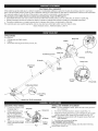 4
4
-
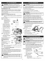 5
5
-
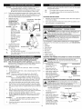 6
6
-
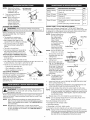 7
7
-
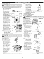 8
8
-
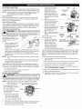 9
9
-
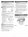 10
10
-
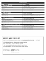 11
11
-
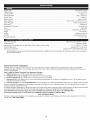 12
12
-
 13
13
-
 14
14
-
 15
15
-
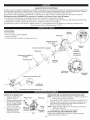 16
16
-
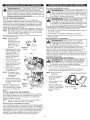 17
17
-
 18
18
-
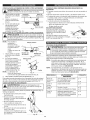 19
19
-
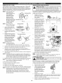 20
20
-
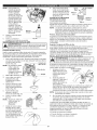 21
21
-
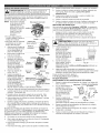 22
22
-
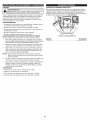 23
23
-
 24
24
-
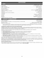 25
25
-
 26
26
-
 27
27
-
 28
28
-
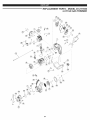 29
29
-
 30
30
-
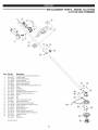 31
31
-
 32
32


Craftsman 316.791930 El manual del propietario
- Categoría
- Podadoras de césped
- Tipo
- El manual del propietario
- Este manual también es adecuado para
en otros idiomas
- English: Craftsman 316.791930 Owner's manual
Artículos relacionados
-
Craftsman 316791840 El manual del propietario
-
MTD 316791900 El manual del propietario
-
-
-
-
-
-
-
-