La página se está cargando ...

I0207 REV.1
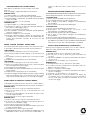
ISTRUZIONI MONTAGGIO SUPPORTO MOBILE
Il kit supporto mobile può essere montato sui modelli
SPIN 4-6.
Per il montaggio seguire attentamente le istruzioni:
BARRIERA SPIN 4:
1) Togliere il tappo rosso dall’estremità dell’asta.
2) Accorciare di circa 70 mm il profilo in gomma antiurto.
3) Inserire il piattino A all’interno dell’asta, quindi avvitare il
supporto mobile.
4) Rimettere il tappo rosso d’estremità.
BARRIERA SPIN 6:
1) Togliere il tappo rosso dall’estremità dell’asta.
2) Posizionare il supporto mobile all’estremità dell’asta e
tracciare i fori di fissaggio (fig.1.)
3) Forare con punta ø5.5 mm (fig.2.)
4) Inserire il piattino A all’interno dell’asta ,quindi avvitare il
supporto mobile (fig.3.).
5) Rimettere il tappo rosso d’estremità.
6) Regolare l’altezza tramite il tirante di regolazione (B),
ricordando che con asta in posizione orizzontale il supporto
mobile deve rimanere sollevato di circa 0.5 cm da
terra.(fig.4.)
MOBILE SUPPORT ASSEMBLY INSTRUCTIONS
The mobile support kit can be mounted on the Spin 4-6 models.
To assemble, carefully follow the instructions listed below:
SPIN 4 BARRIER:
1) Remove the red plug from the end of the beam.
2) Shorten the impact-resistant rubber section by about 70
mm.
3) Insert plate A inside the beam then screw inthe mobile
support.
4) Replace the red plug at the end of the beam.
SPIN6 BARRIER:
1) Remove the red plug from the end of the beam.
2) Place the mobilemsupport at the end of the beam and
trace the attachment holes (fig1).
3) Drill using a ø 5.5 mm bit (fig2).
4) Insert plate A inside the beam and then screw the mobile
support (fig3).
5) Replace the red plug at the end of the beam.
6) Adjust the height using the adjustement tie rod (B), recalling
that with thebeam in the horizontal position,the mobile
support must remain about 0.5 cm off the ground (fig4).
INSTRUCTIONS DE MONTAGE SUPPORT MOBILE
Le kit support mobile peut être monté sur les modéles SPIN 4-6.
Pour le montage, suivre attentivement les instructions suivantes:
BARRIÉRE SPIN 4:
1) Enlever le bouchon rouge de l’extrêmité de la lisse.
2) Raccourcir d’environ 70 mm. le profilé pare-choc en
caoutchouc.
3) Introduire le petitr plateau A à l’intérieur de la lisse, puis
visser le support mobile.
4) Remettre le bouchon rouge d’extrêmité.
BARRIÉRE SPIN 6:
1) Enlever le bouchon rouge de l’extrêmité de la lisse.
2) Positionner le support mobile à l’extrêmité de la lisse et
tracer les trous de fixation (fig1)
3) Percer avec pointe ø5.5 mm (fig 2)
4) Introduire le petit plateau A à l’intérieur de la lisse,puis visser
le support mobile (fig3).
5) Remettre le bouchon rouge d’extrêmité.
6) Régler la hauteur au moyen du tirant de réglage (B), en se
rappellant qu’avec la lisse en position horizzontale , le
support mobile doit rester soulevé à environ 0.5, du sol
(fig4).
MONTAGEANLEITUNGEN FÜR MOBILSTÜZE
Der Bausatz Mobilstüze kann auf die Modelle SPIN4-6 montiert werden.
Bei Montage aufmerksam die Anleitungen verfolgen:
SCHRANKE SPIN4:
1) Roten stopfen am balkenende antfernen
2) Anschlaggummiprofil um etwa 70 mm Kürzen.
3) Fuß A innen in den Balken einfügen und Mobilstütze
anschrauben.
4) Roten Stopfen wieder am Ende anbringen
SCHRANKE SPIN6:
1) Roten stopfen am balkenende antfernen
2) Mobilstütze an Balkenende positioner und
Befestigungslocher Markieren (abb1)
3) Mit ø5.5mm-Bohrspitze durchboren (abb2)
4) Fuß A innen in den Balken einfugen und Mobilstütze
anschrauben
5) Roten Stopfen wieder am Ende anbringen
6) Höhe mittels Regulierzugstab einstellen unter Beachtung
(B) ,daß bei horizontaler Position des Balkensdie Mobilstütze
etwa 0.5 mm vom Boden entfernt bleiben soll (abb3)
INSTRUCCIONES DE MONTAJE DEL SOPORTE MÓVIL
El kitsoporte móvil puede montarse en los modelos SPIN4-6.
Para el montaje siga atentamente las instrucciones:
BARRERA SPIN 4
1) Extraiga el tapon de rojo del extremo del màstil.
2) Recorte unos 70 mm el perfil de goma a pruebra de
choques.
3) Introduzca el platillo A en el interior del mástil y entornille el
soporte móvil.
4) Vuelva a colocar el tapón rojo en el extremo.
BARRERA SPIN 6
1) Extraiga el tapon de rojo del extremo del màstil.
2) Coloque el soporte móvil al extremo del mástil y trace los
agujeros de sujeción (fig1)
3) Perfore con punta ø 5.5 mm (fig2)
4) Introduzcael platillo A en el interior del mástil y entornille el
soporte móvil(fig3).
5) Vuelva a colocar el tapón rojo en el extremo.
6) Ajuste la altura por medio del tirante de ajuste (B)
,recordando que con el mástil en posición horizontal el
soporte móvil debe permanecer levantado de unos 0.5
cm del suelo (fig4).
Transcripción de documentos
ISTRUZIONI MONTAGGIO SUPPORTO MOBILE Il kit supporto mobile può essere montato sui modelli SPIN 4-6. Per il montaggio seguire attentamente le istruzioni: BARRIERA SPIN 4: 1) Togliere il tappo rosso dall’estremità dell’asta. 2) Accorciare di circa 70 mm il profilo in gomma antiurto. 3) Inserire il piattino A all’interno dell’asta, quindi avvitare il supporto mobile. 4) Rimettere il tappo rosso d’estremità. BARRIERA SPIN 6: 1) Togliere il tappo rosso dall’estremità dell’asta. 2) Posizionare il supporto mobile all’estremità dell’asta e tracciare i fori di fissaggio (fig.1.) 3) Forare con punta ø5.5 mm (fig.2.) 4) Inserire il piattino A all’interno dell’asta ,quindi avvitare il supporto mobile (fig.3.). 5) Rimettere il tappo rosso d’estremità. 6) Regolare l’altezza tramite il tirante di regolazione (B), ricordando che con asta in posizione orizzontale il supporto mobile deve rimanere sollevato di circa 0.5 cm da terra.(fig.4.) support mobile doit rester soulevé à environ 0.5, du sol (fig4). MONTAGEANLEITUNGEN FÜR MOBILSTÜZE Der Bausatz Mobilstüze kann auf die Modelle SPIN4-6 montiert werden. Bei Montage aufmerksam die Anleitungen verfolgen: SCHRANKE SPIN4: 1) Roten stopfen am balkenende antfernen 2) Anschlaggummiprofil um etwa 70 mm Kürzen. 3) Fuß A innen in den Balken einfügen und Mobilstütze anschrauben. 4) Roten Stopfen wieder am Ende anbringen SCHRANKE SPIN6: 1) Roten stopfen am balkenende antfernen 2) Mobilstütze an Balkenende positioner und Befestigungslocher Markieren (abb1) 3) Mit ø5.5mm-Bohrspitze durchboren (abb2) 4) Fuß A innen in den Balken einfugen und Mobilstütze anschrauben 5) Roten Stopfen wieder am Ende anbringen 6) Höhe mittels Regulierzugstab einstellen unter Beachtung (B) ,daß bei horizontaler Position des Balkensdie Mobilstütze etwa 0.5 mm vom Boden entfernt bleiben soll (abb3) MOBILE SUPPORT ASSEMBLY INSTRUCTIONS INSTRUCCIONES DE MONTAJE DEL SOPORTE MÓVIL The mobile support kit can be mounted on the Spin 4-6 models. To assemble, carefully follow the instructions listed below: SPIN 4 BARRIER: 1) Remove the red plug from the end of the beam. 2) Shorten the impact-resistant rubber section by about 70 mm. 3) Insert plate A inside the beam then screw inthe mobile support. 4) Replace the red plug at the end of the beam. SPIN6 BARRIER: 1) Remove the red plug from the end of the beam. 2) Place the mobilemsupport at the end of the beam and trace the attachment holes (fig1). 3) Drill using a ø 5.5 mm bit (fig2). 4) Insert plate A inside the beam and then screw the mobile support (fig3). 5) Replace the red plug at the end of the beam. 6) Adjust the height using the adjustement tie rod (B), recalling that with thebeam in the horizontal position,the mobile support must remain about 0.5 cm off the ground (fig4). El kitsoporte móvil puede montarse en los modelos SPIN4-6. Para el montaje siga atentamente las instrucciones: BARRERA SPIN 4 1) Extraiga el tapon de rojo del extremo del màstil. 2) Recorte unos 70 mm el perfil de goma a pruebra de choques. 3) Introduzca el platillo A en el interior del mástil y entornille el soporte móvil. 4) Vuelva a colocar el tapón rojo en el extremo. BARRERA SPIN 6 1) Extraiga el tapon de rojo del extremo del màstil. 2) Coloque el soporte móvil al extremo del mástil y trace los agujeros de sujeción (fig1) 3) Perfore con punta ø 5.5 mm (fig2) 4) Introduzcael platillo A en el interior del mástil y entornille el soporte móvil(fig3). 5) Vuelva a colocar el tapón rojo en el extremo. 6) Ajuste la altura por medio del tirante de ajuste (B) ,recordando que con el mástil en posición horizontal el soporte móvil debe permanecer levantado de unos 0.5 cm del suelo (fig4). INSTRUCTIONS DE MONTAGE SUPPORT MOBILE Le kit support mobile peut être monté sur les modéles SPIN 4-6. Pour le montage, suivre attentivement les instructions suivantes: BARRIÉRE SPIN 4: 1) Enlever le bouchon rouge de l’extrêmité de la lisse. 2) Raccourcir d’environ 70 mm. le profilé pare-choc en caoutchouc. 3) Introduire le petitr plateau A à l’intérieur de la lisse, puis visser le support mobile. 4) Remettre le bouchon rouge d’extrêmité. BARRIÉRE SPIN 6: 1) Enlever le bouchon rouge de l’extrêmité de la lisse. 2) Positionner le support mobile à l’extrêmité de la lisse et tracer les trous de fixation (fig1) 3) Percer avec pointe ø5.5 mm (fig 2) 4) Introduire le petit plateau A à l’intérieur de la lisse,puis visser le support mobile (fig3). 5) Remettre le bouchon rouge d’extrêmité. 6) Régler la hauteur au moyen du tirant de réglage (B), en se rappellant qu’avec la lisse en position horizzontale , le I0207 REV.1-
 1
1
-
 2
2


