Klein Tools KLEIN TOOLS Manual de usuario
- Tipo
- Manual de usuario

Dwg Name: VDV500-820E-1390411ART
Dwg No: 1390411 Rev: B
Pkg Dwg Ref: 1790 ECO No: 041011
Finish Coat Requirements: N/A
FRANÇAIS pg. 17
DEUTSCH pg. 9
ESPAÑOL pg. 25
INSTRUCTION MANUAL
ENGLISH
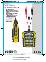
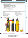
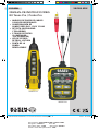
VDV500-820E
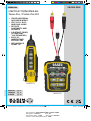
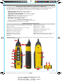
Toner-Pro / Probe-Pro Kit
• TRACE INDIVIDUAL
OR PAIRED WIRES
• TEST RJ11, RJ12
AND RJ45 JACKS
• DETECTS
CONTINUITY AND
POLARITY
• 5 DISTINCT TONES
(3 CONSTANT,
2 ALTERNATING)
• EASY-TO-
UNDERSTAND
STATUS LEDs
• REPLACEABLE
PROBE TIP
VDV500-063
VDV500-123
VDV500-820E-1390411ART - Pro Tone and Probe Kit - EUROPE.indd 1VDV500-820E-1390411ART - Pro Tone and Probe Kit - EUROPE.indd 1 8/2/21 10:04 AM8/2/21 10:04 AM

2
ENGLISH
Dwg Name: VDV500-820E-1390411ART
Dwg No: 1390411 Rev: B
Pkg Dwg Ref: 1790 ECO No: 041011
Finish Coat Requirements: N/A
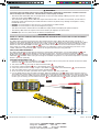
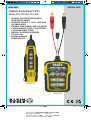
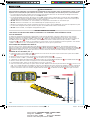
GENERAL SPECIFICATIONS - VDV500-063 TONER-PRO
The Klein Tools VDV500-063 Toner-Pro is a professional-series tone generator for wire identification, wire
tracing and wire pair identification on non-energised wires. It features several tone frequencies and a strong
power output for tracing wires.
• Operating Altitude: 6562' (2000 m) maximum
• Relative Humidity: 10% to 90%, non-condensing
• Operating Temp: 14° to 122°F (-10° to 50°C)
• Storage Temp: -4° to 140°F (-20° to 60°C)
• Dimensions: 2.5" x 5" x 1" (64 x 127 x 25 mm)
• Weight: 7.4 oz (210 g) including batteries
• Battery Type: 4 x 1.5V AAA Alkaline
• Battery Life: Active: 120 hours
Standby/Storage: 3 years
• Auto Power-Off: After 60 minutes of inactivity
• Tones: Constant: 800 Hz, 1000 Hz, 1500 Hz
Alternating: 800/1000 Hz, 1000/1500 Hz
• Tone Power: 8 dBm
• Continuity Indication: Less than 10kΩ
• Voltage Protection: Test Mode: 60 V
Tone Mode:
20 V through external 600 Ω
Specifications subject to change.
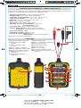
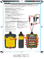
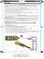
T1
TEST MODE Indicator
T9
Power On/Off Button
T2
‘NRM’ (Normal) Polarity Indicator
T10
TEST/TONE Button
T3
‘REV’ (Reverse) Polarity Indicator
T11
Battery Status Indicator
T4
‘CONT’ (Continuity) Indicator
T12
Lanyard Slot
T5
TONE MODE Indicator
T13
RJ11 Test Plug
T6
Tone Frequency Indicators
T14
ABN (Angled Bed-of-Nails) Test Clips
T7
Tone Mode Down selector button
T15
Battery Cover
T8
Tone Mode Up selector button
T16
Battery Cover Screw (No. 2 Phillips)
T1
T5
T7
T9
T8
T10
T13
T12
T14
T11
T2
T3
T4
T6
FEATURE DETAILS
T16
T15
VDV500-820E-1390411ART - Pro Tone and Probe Kit - EUROPE.indd 2VDV500-820E-1390411ART - Pro Tone and Probe Kit - EUROPE.indd 2 8/2/21 10:04 AM8/2/21 10:04 AM

3
Dwg Name: VDV500-820E-1390411ART
Dwg No: 1390411 Rev: B
Pkg Dwg Ref: 1790 ECO No: 041011
Finish Coat Requirements: N/A
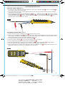
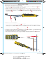
GENERAL SPECIFICATIONS - VDV500-123 PROBE-PRO
The Klein Tools VDV500-123 Probe-Pro is a professional-series tone tracer, featuring an inductive probe with a
speaker for amplification, and an LED light for use in dark spaces. It also features a headphone jack for use in
extreme noise environments.
• Operating Altitude: 6562’ (2000 m) maximum
• Relative Humidity: 10% to 90%, non-condensing
• Operating Temp: 14° to 122°F (-10° to 50°C)
• Storage Temp: -4° to 140°F (-20° to 60°C)
• Dimensions: 1.75" x 8.88" x 1.13" (44 x 226 x 29 mm)
• Weight: 5.7 oz (161.6 g) including batteries
• Battery Type: 4 x 1.5V AAA Alkaline
• Battery Life: Active: 25 hours
Standby/Storage: 3 years
• Auto Power-Off: After 10 minutes of inactivity
Specifications subject to change.
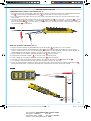
P1
Replaceable Inductive Polymer Tip (VDV999-068)
P10
Lanyard Slot
P2
Worklight
P11
"-" (Negative) Terminal
P3
Worklight On/Off Button
P12
"+" (Positive) Terminal
P4
Signal Strength Indicator
P13
Terminal Release Buttons
P5
Power On/Off Button
P14
Verification Indicator
P6
Volume Increase Button
P15
Battery Cover
P7
Volume Decrease Button
P16
Battery Cover Screw (No. 2 Phillips)
P8
Battery Status Indicator
P17
3.5 mm Headphone Jack*
P9
Speaker
P2
P17
P3
P4
P5
P6
P11 P12
P7
P9
P10
P8
P1
*CAUTION: Excessive volume can cause permanent hearing damage. Use as low a volume as possible.
P14
FEATURE DETAILS
P13
P15
P16
VDV500-820E-1390411ART - Pro Tone and Probe Kit - EUROPE.indd 3VDV500-820E-1390411ART - Pro Tone and Probe Kit - EUROPE.indd 3 8/2/21 10:04 AM8/2/21 10:04 AM

4
ENGLISH
Dwg Name: VDV500-820E-1390411ART
Dwg No: 1390411 Rev: B
Pkg Dwg Ref: 1790 ECO No: 041011
Finish Coat Requirements: N/A
WARNINGS
To ensure safe operations and service of the instruments, follow these instructions. Failure to observe
these warnings can result in re, electric shock, severe injury or death.
• The Toner-Pro and Probe-Pro are designed for use on extra-low voltage cabling systems (less than 60
volts) for testing when NOT energised.
• The maximum voltage across ABN Test Clips of the Toner-Pro is 60 volts in Test mode, and 20 volts in
Continuity mode. Connecting the Probe-Pro to live mains AC power may damage it and pose a safety
hazard for the user.
• DO NOT use instruments if they are wet, as it could pose a shock hazard.
• DO NOT use instruments if they are damaged in any way.
• Turn off instruments and disconnect all ABN Test Clips before attempting to replace batteries.
• The battery door must be in place and secure before you operate the instrument.
• DO NOT open the case, other than the battery compartment.
OPERATING INSTRUCTIONS
READ ALL INSTRUCTIONS BEFORE OPERATING AND RETAIN INSTRUCTIONS FOR FUTURE REFERENCE
CONTINUITY TEST
The Toner-Pro transmits frequencies on non-energised wires only. When the Toner-Pro is turned on, a
continuity test will be performed to determine if the 2 wires to be traced are in close proximity to each other,
without a conductive path between them. The ‘CONT’ Indicator
T4
will illuminate green to indicate a pass.
Attach the red and black ABN Test Clips
T14
to the wires to be tested. If the resistance of the circuit is less
than 10kΩ, the ‘CONT’ Indicator
T4
will illuminate red, indicating a short, and no toning can occur. If the
"CONT" Indicator is illuminated green, a tone can be generated and you may proceed.
SELECTING TONE FREQUENCY
The Toner-Pro defaults to the 800 Hz frequency setting when powered on. Use the Tone Mode Up
T8
and
Tone Mode Down
T7
selector buttons to change the frequency. The Tone Frequency Indicators
T6
will
display the frequency being transmitted. If an alternating tone is selected, the two respective Tone Frequency
Indicators
T6
will blink.
Tones will cycle through the available frequencies in a continuous loop when a selector
button is pressed repeatedly.
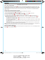
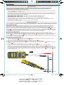
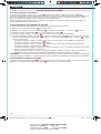
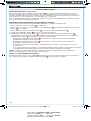
TRACING PAIRED WIRES (FIG. 1)
1. Connect the Toner-Pro’s red ABN Test Clip
T14
to one of the wires of the pair to be traced. Connect the black
ABN Test Clip
T14
to the other wire to be traced.
2. Turn Toner-Pro on by pressing the Power On/Off button
T9
.
3. Check the ‘CONT’ Indicator
T4
. If it is illuminated green, you may proceed.
4. Select the preferred tone setting using the
Tone Mode Up
T8
and/or
Tone Mode Down
T7
selector buttons.
5. Turn the Probe-Pro on by pressing the Power On/Off button
P5
.
6. At the far end of the cable, spread the wires apart at least 2" (51 mm), if possible.
7. Use the Probe-Pro to scan the cable’s wire pairs. Move the Probe-Pro's tip
P1
slowly across the wires (FIG. 1).
The Probe-Pro’s volume will increase as it approaches the toned pair. When the Probe-Pro’s volume is high over
the first wire, low in the middle (between) the two wires, and high over the second wire, you have located the pair
of wires you are tracing. Use the
Volume Increase
P6
and
Volume Decrease
P7
buttons to adjust the volume.
2"
(51 mm)
FIG. 1
VDV500-820E-1390411ART - Pro Tone and Probe Kit - EUROPE.indd 4VDV500-820E-1390411ART - Pro Tone and Probe Kit - EUROPE.indd 4 8/2/21 10:04 AM8/2/21 10:04 AM

5
Dwg Name: VDV500-820E-1390411ART
Dwg No: 1390411 Rev: B
Pkg Dwg Ref: 1790 ECO No: 041011
Finish Coat Requirements: N/A
OPERATING INSTRUCTIONS
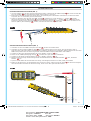
VERIFYING TONED PAIRS (FIG. 2)
1. To verify you have found the toned pair, connect the Toner-Pro's ABN Test Clips
T14
or RJ11 Test Plug
T13
to
one end of the cable and initiate a tone.
2. On the other end of the cable, remove approximately 2 mm (3/32") of the outer jacket of each of the wires
believed to be the toned pair.
3. Insert the wire connected to the red ABN Test Clip
T14
to the
"+" (Positive) Terminal
P12
,
and the wire curently
in the black ABN Test Clip
T14
to the
"-" (Negative) Terminal
P11
. To access the terminals, press their respective
Terminal Release buttons
P13
, insert the wire(s) and release (FIG. 2). The
Verification Indicator
P14
will
illuminate when the correct pair is inserted.
TRACING NON-PAIRED WIRES (FIG. 3)
1. Connect the Toner-Pro’s red ABN Test Clip
T14
to the wire to be traced.
2. Connect the black ABN Test Clip
T14
to another wire in the cable, but preferably not in the same pair (connect
to the ground, if available). When tracing a shielded cable, connect the red ABN Test Clip to the outer shield,
and the black ABN Test Clip to the center conductor or ground.
3. Turn Toner-Pro on by pressing the Power On/Off button
T9
.
4. Check the ‘CONT’ Indicator
T4
. If it is illuminated green, you may proceed.
5. Turn the Probe-Pro on by pressing the Power On/Off button
P5
.
6. Select the preferred tone setting using the
Tone Mode Up
T8
or
Tone Mode Down
T7
selector buttons.
7. At the far end of the cable, spread the wires at least 2" (51 mm) apart, if possible.
8. Use the Probe-Pro to scan the cable’s wire pairs. Move the Probe-Pro's tip
P1
slowly across the wires. The
Probe-Pro’s volume will increase as it approaches the toned wire.
2"
(51 mm)
FIG. 3
FIG. 2
Press
2 mm
(3/32")
VDV500-820E-1390411ART - Pro Tone and Probe Kit - EUROPE.indd 5VDV500-820E-1390411ART - Pro Tone and Probe Kit - EUROPE.indd 5 8/2/21 10:04 AM8/2/21 10:04 AM

6
ENGLISH
Dwg Name: VDV500-820E-1390411ART
Dwg No: 1390411 Rev: B
Pkg Dwg Ref: 1790 ECO No: 041011
Finish Coat Requirements: N/A
OPERATING INSTRUCTIONS
RJ11 / RJ12 / RJ45 TESTING
The Toner-Pro has an RJ11 Test Plug
T13
that can be used in place of the ABN clips to transmit the tone. The
RJ11 plug works with RJ11, RJ12 or RJ45 jacks. The red and black ABN contacts are replaced by the 2 center
conductors of the inserted plug, i.e. Pins 2 and 3 for RJ11, Pins 3 and 4 for RJ12, and Pins 4 and 5 for RJ45.
Use the Probe-Pro to locate the toned wires at the far end of the cable, as described in the TRACING PAIRED
WIRES section.
POLARITY AND VOLTAGE PRESENCE TESTING
The Toner-Pro may be used to test the polarity and type of voltage that is present.
1. Press the
Power On/Off button
T9
on the Toner-Pro.
2. Press the
TEST/TONE Select button
button
T10
. The ‘TEST MODE’ indicator
T1
will illuminate.
3. Connect the
ABN Test Clips
T14
, or insert the
RJ11 Test Plug
T13
.
4. Check the ‘CONT’ Indicator
T4
. If it is illuminated green, you may proceed.
5. The
‘NRM’ (Normal) Polarity Indicator
T2
will illuminate if the red
ABN Test Clip
T14
is connected to the
POTS (Plain Old Telephone Service) in the proper orientation. The
‘REV’ (Reverse) Polarity Indicator
T3
will
illuminate if the wires are reversed.
• The
‘NRM’ (Normal) Polarity Indicator
T2
will illuminate
when the black ABN Test Clip detects a higher
voltage than the red ABN Test Clip.
• The
‘REV’ (Reverse) Polarity Indicator
T3
w
ill illuminate
when the red ABN Test Clip detects a higher voltage
than the black ABN Test Clip.
• The
‘NRM’ (Normal) Polarity Indicator and ‘REV’ (Reverse) Polarity Indicator will both illuminate when an
AC
voltage is present.
• When the
RJ11 Test Plug
is used, the
‘NRM’ (Normal) Polarity Indicator will illuminate on
a correctly wired
and powered POTS (Plain Old Telephone Service) phone jack.
NOTE: The POTS (Plain Old Telephone Service) colour code convention (black/positive, red/negative) is
the opposite of the multimeter colour code convention (red/positive, black/negative).
USING THE PROBE'S WORKLIGHT
The Probe-Pro has a worklight
P2
to aid in illuminating dark or low-light work areas. Press the Worklight On/Off
Button
P3
to turn the light on and off.
VDV500-820E-1390411ART - Pro Tone and Probe Kit - EUROPE.indd 6VDV500-820E-1390411ART - Pro Tone and Probe Kit - EUROPE.indd 6 8/2/21 10:04 AM8/2/21 10:04 AM

7
Dwg Name: VDV500-820E-1390411ART
Dwg No: 1390411 Rev: B
Pkg Dwg Ref: 1790 ECO No: 041011
Finish Coat Requirements: N/A
CUSTOMER SERVICE
KLEIN TOOLS, INC.
450 Bond Street
Lincolnshire, IL 60069
800-553-4676
www.kleintools.com
CLEANING
Be sure instrument is turned off and wipe with a clean, dry lint-free cloth.
Do not use abrasive
cleaners or solvents.
STORAGE
Remove the batteries when
instrument
is not in use for a prolonged period of time. Do not expose to high
temperatures or humidity. After a period of storage in extreme conditions exceeding the limits mentioned in the
GENERAL SPECIFICATIONS section, allow the equipment to return to normal operating conditions before using.
WARRANTY
www.kleintools.com/warranty
DISPOSAL RECYCLE
Do not place equipment and its accessories in the trash. Items must be properly disposed of in
accordance with local regulations. Prior to disposal of this product, please contact Klein Tools for
proper disposal options.
MAINTENANCE
BATTERY REPLACEMENT
When the Low Battery Indicator
P11
or
P8
blinks, the batteries must be replaced.
1. Turn off instrument(s) before attempting to replace the batteries.
2. Loosen screw
T16
,
P16
on the battery cover
T15
,
P15
.
3. Remove and properly dispose of four 1.5V AAA batteries.
4. Install new batteries (note the proper polarity).
5. Replace battery cover and fasten securely with the screw.
PROBE-PRO TIP REPLACEMENT (KLEIN CAT. NO. VDV999-068)
The tip
P1
of the Probe-Pro is replaceable if damaged. To remove and replace tip:
1. Turn tip 1/4 turn and pull gently to remove.
2. Insert new tip with key in the proper orientation and push gently.
3. Rotate 1/4 turn to lock into place.
To avoid risk of electric shock, do not operate while battery door is removed.
VDV500-820E-1390411ART - Pro Tone and Probe Kit - EUROPE.indd 7VDV500-820E-1390411ART - Pro Tone and Probe Kit - EUROPE.indd 7 8/2/21 10:04 AM8/2/21 10:04 AM

8
ENGLISH
Dwg Name: VDV500-820E-1390411ART
Dwg No: 1390411 Rev: B
Pkg Dwg Ref: 1790 ECO No: 041011
Finish Coat Requirements: N/A
NOTES
VDV500-820E-1390411ART - Pro Tone and Probe Kit - EUROPE.indd 8VDV500-820E-1390411ART - Pro Tone and Probe Kit - EUROPE.indd 8 8/2/21 10:04 AM8/2/21 10:04 AM

Dwg Name: VDV500-820E-1390411ART
Dwg No: 1390411 Rev: B
Pkg Dwg Ref: 1790 ECO No: 041011
Finish Coat Requirements: N/A
GEBRAUCHSANLEITUNG
DEUTSCH
VDV500-820E
Toner-Pro-/Probe-Pro-Kit
• ORTUNG VON EINZELNEN KABELN
ODER KABELPAAREN
• PRÜFUNG VON RJ11-, RJ12- UND RJ45-
DATENBUCHSEN
• ERKENNT DURCHGANG UND POLARITÄT
• 5 VERSCHIEDENE TÖNE (3 DAUERTÖNE,
2 ALTERNIERENDE TÖNE)
• EINFACH ZU IDENTIFIZIERENDE
STATUS-LEDs
• AUSTAUSCHBARE
SONDENSPITZE
VDV500-063
VDV500-123
VDV500-820E-1390411ART - Pro Tone and Probe Kit - EUROPE.indd 9VDV500-820E-1390411ART - Pro Tone and Probe Kit - EUROPE.indd 9 8/2/21 10:04 AM8/2/21 10:04 AM

10
DEUTSCH
Dwg Name: VDV500-820E-1390411ART
Dwg No: 1390411 Rev: B
Pkg Dwg Ref: 1790 ECO No: 041011
Finish Coat Requirements: N/A
ALLGEMEINE TECHNISCHE DATEN – VDV500-063 TONER-PRO
Bei diesem VDV500-063 Toner-Pro von Klein Tools handelt es sich um einen professionellen Tongenerator zur
Kabelidentifikation, Kabelortung und Kabelpaaridentifikation bei nicht unter Spannung stehenden Kabeln. Das
Gerät verfügt über mehrere Tonfrequenzen und eine hohe Ausgangsleistung zur Ortung von Kabeln.
• Betriebshöhe: max. 2000m (6562 Fuß)
• Relative Luftfeuchtigkeit: 10 bis 90%, nicht kondensierend
• Betriebstemperatur: -10 °C bis 50 °C (14 °F bis 122 °F)
• Lagertemperatur: -20 °C bis 60 °C (-4 °F bis 140 °F)
• Abmessungen: 64 x 127 x 25 mm (2,5 x 5 x 1Zoll)
• Gewicht: 210 g (7,4 oz) einschließlich Batterien
• Batterietyp: 4 x 1,5V AAA Alkalibatterien
• Batterienutzungsdauer: Aktiver Betrieb: 120Stunden
Standby/Lagerung: 3Jahre
• Automatische Abschaltung: Nach 60 Minuten Inaktivität
• Töne: Dauertöne: 800 Hz, 1.000 Hz, 1.500 Hz
Alternierende Töne: 800Hz/1.000Hz, 1.000Hz/1.500Hz
• Tonleistung: 8dBm
• Durchgangsanzeige: Weniger als 10kΩ
• Spannungsschutz: Prüfmodus: 60V
Tonmodus:
20Volt durch externen 600 Ω
Änderungen der technischen Daten vorbehalten.
T1
T2
T3
T4
T5
T6
T7
T8
„TEST MODE“(PRÜFMODUS)-
Anzeige
Anzeige für „NRM“ (normale) Polarität
Anzeige für „REV“ (umgekehrte)
Polarität
„CONT“(Durchgang)-Anzeige
„TONE MODE“(TONMODUS)-Anzeige
Tonfrequenz-Anzeigen
Auswahltaste für „Tonmodus Abwärts“
Auswahltaste für „Tonmodus Aufwärts“
T9
T10
T11
T12
T13
T14
T15
T16
Taste „On/Off“ („Ein/Aus“)
Taste „TEST/TONE“ („TONPRÜFUNG“)
Batteriestatus-Anzeige
Schlitz für Trageschlaufe
RJ11-Teststecker
ABN(Angled Bed of Nails)-Testclips
Batterieabdeckung
Schraube der Batterieabdeckung
(Nr. 2 Phillips)
FUNKTIONSDETAILS
T1
T5
T7
T9
T8
T10
T13
T12
T14
T11
T2 T3
T4
T6
T16
T15
VDV500-820E-1390411ART - Pro Tone and Probe Kit - EUROPE.indd 10VDV500-820E-1390411ART - Pro Tone and Probe Kit - EUROPE.indd 10 8/2/21 10:04 AM8/2/21 10:04 AM

11
Dwg Name: VDV500-820E-1390411ART
Dwg No: 1390411 Rev: B
Pkg Dwg Ref: 1790 ECO No: 041011
Finish Coat Requirements: N/A
ALLGEMEINE TECHNISCHE DATEN – VDV500-123 PROBE-PRO
Bei der VDV500-123 Probe-Pro von Klein Tools handelt es sich um eine professionelle Tonortungssonde. Die
induktive Sonde verfügt über einen Lautsprecher zur Verstärkung und eine LED-Lampe für den Einsatz in dunklen
Räumen. Mit der integrierten Kopfhörerbuchse ist eine Nutzung auch in extrem lauten Umgebungen möglich.
• Betriebshöhe: max. 2000m (6562 Fuß)
• Relative Luftfeuchtigkeit: 10 bis 90%, nicht kondensierend
• Betriebstemperatur: -10 °C bis 50 °C (14 °F bis 122 °F)
• Lagertemperatur: -20 °C bis 60 °C (-4 °F bis 140 °F)
• Abmessungen: 44 x 226 x 29mm (1,75 x 8,88 x 1,13Zoll)
• Gewicht: 161,6 g (5,7 oz) einschließlich Batterien
• Batterietyp: 4 x 1,5V AAA Alkalibatterien
• Batterienutzungsdauer: Aktiver Betrieb: 25Stunden
Standby/Lagerung: 3Jahre
• Automatische Abschaltung: Nach 10 Minuten Inaktivität
Änderungen der technischen Daten vorbehalten.
P1
P2
P3
P4
P5
P6
P7
P8
P9
Austauschbare induktive Polymer-Spitze (VDV999-068)
Arbeitslicht
Ein-/Ausschalttaste für das Arbeitslicht
Signalstärken-Anzeige
Taste „On/Off“ („Ein/Aus“)
„Lauter“-Taste
„Leiser“-Taste
Batteriestatus-Anzeige
Lautsprecher
P10
P11
P12
P13
P14
P15
P16
P17
Schlitz für Trageschlaufe
Anschluss „-“ (negativ)
Anschluss „+“ (positiv)
Anschlussentriegelungstasten
Prüfanzeige
Batterieabdeckung
Schraube der Batterieabdeckung
(Nr.2Phillips)
3,5-mm-Kopfhörerbuchse*
*VORSICHT: Eine übermäßige Lautstärke kann zu dauerhaften Gehörschäden führen. Verwenden Sie eine
möglichst niedrige Lautstärke.
FUNKTIONSDETAILS
P2
P17
P3
P4
P5
P6
P11 P12
P7
P9
P10
P8
P1
P14
P13
P15
P16
VDV500-820E-1390411ART - Pro Tone and Probe Kit - EUROPE.indd 11VDV500-820E-1390411ART - Pro Tone and Probe Kit - EUROPE.indd 11 8/2/21 10:04 AM8/2/21 10:04 AM

12
DEUTSCH
Dwg Name: VDV500-820E-1390411ART
Dwg No: 1390411 Rev: B
Pkg Dwg Ref: 1790 ECO No: 041011
Finish Coat Requirements: N/A
WARNUNGEN
Beachten Sie die folgenden Anweisungen, um einen sicheren Betrieb und eine sichere Wartung der Geräte
zu gewährleisten. Bei Nichtbeachtung dieser Warnungen können Brände, Stromschläge und schwere bis
lebensgefährliche Verletzungen verursacht werden.
• Toner-Pro und Probe-Pro sind zum Testen von Kabelsystemen mit Kleinspannungen (weniger als 60Volt) ausgelegt,
wenn diese NICHT unter Spannung stehen.
• Die maximale Spannung der ABN-Testclips des Toner-Pro beträgt 60V im Prüfmodus und 20V im Durchgangsmodus.
Der Anschluss des Probe-Pro an spannungsführende Wechselstromleitungen kann zur Beschädigung des Gerätes
führen und die Sicherheit des Benutzers gefährden.
• VERWENDEN SIE DIE GERÄTE NICHT, wenn diese nass sind, da Stromschlaggefahr besteht.
• VERWENDEN SIE DIE GERÄTE NICHT, wenn diese in irgendeiner Weise beschädigt sind.
• Schalten Sie die Geräte ab und entfernen Sie alle ABN-Testclips, bevor Sie die Batterien austauschen.
• Die Batterieabdeckung muss vor dem Betrieb des Geräts an ihrem vorgesehenen Platz sein und gesichert werden.
• ÖFFNEN SIE DAS GEHÄUSE NICHT an anderen Stellen als dem Batteriefach.
BETRIEBSANLEITUNG
BITTE LESEN SIE VOR DEM BETRIEB DIE ANLEITUNG UND BEWAHREN SIE DIESE ZUM SPÄTEREN NACHSCHLAGEN AUF.
DURCHGANGSPRÜFUNG
Der Toner-Pro übermittelt ausschließlich Frequenzen von nicht unter Spannung stehenden Kabeln. Ist der Toner-Pro
eingeschaltet, wird eine Durchgangsprüfung durchgeführt, um festzustellen, ob die beiden zu ortenden Kabel ohne
dazwischen liegende Leiterbahn nahe beieinander positioniert sind. Die „CONT“(Durchgang)-Anzeige
T4
leuchtet
grün auf, um eine bestandene Prüfung anzuzeigen. Befestigen Sie die roten und schwarzen ABN-Testclips
T14
an den zu
überprüfenden Kabeln. Wenn der Widerstand des Stromkreises geringer als 10kΩ ist, leuchtet die „CONT“(Durchgang)-
Anzeige
T4
rot auf, was auf einen Kurzschluss hinweist, und es kann keine Tonortung durchgeführt werden. Leuchtet die
„CONT“(Durchgang)-Anzeige grün, kann ein Ton generiert werden und Sie können fortfahren.
AUSWAHL DER TONFREQUENZ
Der Toner-Pro ist beim Einschalten standardmäßig auf eine Frequenz von 800 Hz eingestellt. Verwenden Sie die
Auswahltasten für „Tonmodus Aufwärts“
T8
und „Tonmodus Abwärts“
T7
, um die Frequenz zu ändern. Die Tonfrequenz-
Anzeigen
T6
zeigen die Frequenz an, die übermittelt wird. Bei Auswahl eines alternierenden Tons blinken die beiden
entsprechenden Tonfrequenz-Anzeigen
T6
.
Die Töne wechseln zwischen den verfügbaren Frequenzen in Dauerschleife, wenn
eine Auswahltaste mehrmals gedrückt wird.
ORTUNG VON KABELPAAREN (ABB. 1)
1. Verbinden Sie den roten ABN-Testclip des Toner-Pro
T14
mit einem der beiden zu ortenden Kabel. Verbinden Sie den
schwarzen ABN-Testclip
T14
mit dem anderen zu ortenden Kabel.
2. Schalten Sie den Toner-Pro durch Drücken der Taste „On/Off“ („Ein/Aus“)
T9
ein.
3. Prüfen Sie die „CONT“(Durchgang)-Anzeige
T4
. Leuchtet diese grün, können Sie fortfahren.
4. Wählen Sie die bevorzugte Toneinstellung mithilfe der Auswahltasten für
„Tonmodus Aufwärts“
T8
und/oder
„Tonmodus
Abwärts“
T7
aus.
5. Schalten Sie die Probe-Pro durch Drücken der Taste „On/Off“ („Ein/Aus“)
P5
ein.
6. Spreizen Sie die Kabel am hinteren Ende der Leitung, wenn möglich, mindestens 51 mm (2 Zoll) auseinander.
7. Nutzen Sie die Probe-Pro, um die Kabelpaare der Leitung zu scannen. Fahren Sie mit der Spitze
P1
der Probe-Pro
langsam über die Kabel (ABB. 1). Die Lautstärke der Probe-Pro steigt, wenn sie sich dem georteten Paar nähert. Wenn die
Lautstärke der Probe-Pro über dem ersten Kabel hoch, in der Mitte der beiden Kabel niedrig und über dem zweiten Kabel
hoch ist, haben Sie das Kabelpaar gefunden, das Sie orten. Verwenden Sie die Tasten
„Lauter“
P6
und
„Leiser“
P7
, um die
Lautstärke anzupassen.
51 mm
(2 Zoll)
ABB. 1
VDV500-820E-1390411ART - Pro Tone and Probe Kit - EUROPE.indd 12VDV500-820E-1390411ART - Pro Tone and Probe Kit - EUROPE.indd 12 8/2/21 10:04 AM8/2/21 10:04 AM

13
Dwg Name: VDV500-820E-1390411ART
Dwg No: 1390411 Rev: B
Pkg Dwg Ref: 1790 ECO No: 041011
Finish Coat Requirements: N/A
BETRIEBSANLEITUNG
PRÜFUNG VON GEORTETEN PAAREN (ABB. 2)
1. Um zu bestätigen, dass Sie das geortete Paar gefunden haben, verbinden Sie die ABN-Testclips
T14
des Toner-Pro oder den
RJ11-Teststecker
T13
mit einem Ende des Kabels und erzeugen Sie einen Ton.
2. Entfernen Sie am anderen Ende der Leitung etwa 2mm (3/32 Zoll) des Außenmantels jedes Kabels, bei denen Sie davon
ausgehen, dass es sich um das geortete Paar handelt.
3. Führen Sie das Kabel, das mit dem roten ABN-Testclip
T14
verbunden ist, in den
Anschluss „+“ (positiv)
P12
und das
aktuell mit dem schwarzen ABN-Testclip
T14
verbundene Kabel in den
Anschluss „-“ (negativ)
P11
ein. Zum Zugriff auf die
Anschlüsse drücken Sie die entsprechenden
Anschlussentriegelungstasten
P13
, führen Sie das/die Kabel ein und lassen Sie
dann los (ABB. 2). Die
Prüfanzeige
P14
leuchtet, wenn das korrekte Paar eingeführt wurde.
ORTUNG VON UNGEPAARTEN KABELN (ABB. 3)
1. Verbinden Sie den roten ABN-Testclip des Toner-Pro
T14
mit dem zu ortenden Kabel.
2. Verbinden Sie den schwarzen ABN Test Clip
T14
mit einem anderen Kabel in der Leitung, aber vorzugsweise nicht in
demselben Paar (mit dem Erdleiter verbinden, wenn verfügbar). Bei Ortung von geschirmten Kabeln verbinden Sie den roten
ABN-Testclip mit der äußeren Schirmung und den schwarzen ABN-Testclip mit dem Mittel- oder Erdleiter.
3. Schalten Sie den Toner-Pro durch Drücken der Taste „On/Off“ („Ein/Aus“)
T9
ein.
4. Prüfen Sie die „CONT“(Durchgang)-Anzeige
T4
. Leuchtet diese grün, können Sie fortfahren.
5. Schalten Sie die Probe-Pro durch Drücken der Taste „On/Off“ („Ein/Aus“)
P5
ein.
6. Wählen Sie die bevorzugte Toneinstellung mithilfe der Auswahltasten für
„Tonmodus Aufwärts“
T8
oder
„Tonmodus
Abwärts“
T7
aus.
7. Spreizen Sie die Kabel am hinteren Ende der Leitung, wenn möglich, mindestens 51 mm (2 Zoll) auseinander.
8. Nutzen Sie die Probe-Pro, um die Kabelpaare der Leitung zu scannen. Fahren Sie mit der Spitze
P1
der Probe-Pro langsam
über die Kabel. Die Lautstärke der Probe-Pro steigt, wenn sie sich dem georteten Kabel nähert.
51 mm
(2 Zoll)
ABB. 3
ABB. 2
Drücken
2 mm
(3/32 Zoll)
VDV500-820E-1390411ART - Pro Tone and Probe Kit - EUROPE.indd 13VDV500-820E-1390411ART - Pro Tone and Probe Kit - EUROPE.indd 13 8/2/21 10:05 AM8/2/21 10:05 AM

14
DEUTSCH
Dwg Name: VDV500-820E-1390411ART
Dwg No: 1390411 Rev: B
Pkg Dwg Ref: 1790 ECO No: 041011
Finish Coat Requirements: N/A
BETRIEBSANLEITUNG
RJ11-/RJ12-/RJ45-TESTS
Der Toner-Pro verfügt über einen RJ11-Teststecker
T13
, der anstelle der ABN-Clips zur Tonübertragung
verwendet werden kann. Der RJ11-Stecker ist mit RJ11- RJ12- oder RJ45-Datenbuchsen kompatibel. Die
roten und schwarzen ABN-Kontakte werden durch die 2 Mittelleiter des eingesteckten Steckers ersetzt, d.h.
Kontaktstifte 2 und 3 für RJ11, Kontaktstifte 3 und 4 für RJ12 und Kontaktstifte 4 und 5 für RJ45.
Verwenden Sie Probe-Pro zum Erkennen der georteten Kabel am hinteren Ende der Leitung (wie im Abschnitt
ORTUNG VON KABELPAAREN beschrieben).
PRÜFUNG DER POLARITÄT UND DES ANLIEGENS VON SPANNUNG
Der Toner-Pro kann zur Prüfung der Polarität und der Art der anliegenden Spannung verwendet werden.
1. Drücken Sie die
„On/Off“ („Ein/Aus“)
T9
auf dem Toner-Pro.
2. Drücken Sie die
Taste „TEST/TONE“ („TONPRÜFUNG“)
T10
.Die „TEST MODE“(PRÜFMODUS)-Anzeige
T1
leuchtet auf.
3. Verbinden Sie die
ABN-Testclips
T14
oder stecken Sie den
RJ11-Teststecker
T13
ein.
4. Prüfen Sie die „CONT“(Durchgang)-Anzeige
T4
. Leuchtet diese grün, können Sie fortfahren.
5. Die
Anzeige für „NRM“ (normale) Polarität
T2
leuchtet, wenn der rote
ABN-Testclip
T14
mit dem analogen
Telefondienst in korrekter Ausrichtung verbunden ist. Die
Anzeige für „REV“ (umgekehrte) Polarität
T3
leuchtet,
wenn die Kabel eine umgekehrte Polung aufweisen.
• Die
Anzeige für „NRM“ (normale) Polarität
T2
leuchtet
, wenn der schwarze ABN-Testclip eine höhere
Spannung als der rote ABN-Testclip feststellt.
• Die
Anzeige für „REV“ (umgekehrte) Polarität
T3
leuchtet
, wenn der rote ABN-Testclip eine höhere
Spannung als der schwarze ABN-Testclip feststellt.
• Die
Anzeigen für „NRM“ (normale) Polarität und „REV“ (umgekehrte) Polarität leuchten beide auf, wenn
Wechselspannung vorliegt.
• Bei Verwendung des
RJ11-Teststeckers
leuchtet die
Anzeige für „NRM“ (normale) Polarität
bei einem
ordnungsgemäß verdrahteten und gespeisten Telefon des analogen Telefondienstes.
HINWEIS: Die Festlegungen des analogen Telefondienstes zum Farbcode (schwarz/positiv, rot/negativ)
stehen im Gegensatz zu den Festlegungen des Farbcodes für Multimeter (rot/positiv, schwarz/negativ).
VERWENDUNG DES ARBEITSLICHTS DER SONDE
Die Probe-Pro verfügt über ein Arbeitslicht
P2
zur Unterstützung in dunklen Räumen oder bei schlechter
Beleuchtung. Drücken Sie die Ein-/Ausschalttaste für das Arbeitslicht
P3
, um das Licht ein- und auszuschalten.
VDV500-820E-1390411ART - Pro Tone and Probe Kit - EUROPE.indd 14VDV500-820E-1390411ART - Pro Tone and Probe Kit - EUROPE.indd 14 8/2/21 10:05 AM8/2/21 10:05 AM

15
Dwg Name: VDV500-820E-1390411ART
Dwg No: 1390411 Rev: B
Pkg Dwg Ref: 1790 ECO No: 041011
Finish Coat Requirements: N/A
KUNDENSERVICE
NetPeppers
Perchastr. 8e
82319 Starnberg
+49-89-219097300
www.netpeppers.com
REINIGUNG
Stellen Sie sicher, dass das Gerät ausgeschaltet ist, und wischen Sie es mit einem sauberen, trockenen
und faserfreien Tuch ab.
Verwenden Sie keine Scheuer- oder Lösungsmittel.
LAGERUNG
Entnehmen Sie die Batterien, wenn das
Gerät
über einen längeren Zeitraum nicht verwendet wird. Setzen
Sie das Gerät keinen hohen Temperaturen oder Luftfeuchtigkeiten aus. Wurde das Gerät einige Zeit unter
extremen Bedingungen außerhalb der in den ALLGEMEINEN TECHNISCHEN DATEN angegebenen Grenzwerte
aufbewahrt, stellen Sie zunächst wieder normale Betriebsbedingungen her, bevor Sie es verwenden.
GARANTIE
www.kleintools.com/warranty
ENTSORGUNG/RECYCLING
Entsorgen Sie das Gerät und sein Zubehör nicht über den Hausmüll. Gerät und Zubehör müssen den
lokalen Vorschriften entsprechend entsorgt werden. Weitere Informationen finden Sie unter
www.stiftung-ear.de oder www.bmlfuw.gv.at.
WARTUNG
BATTERIEWECHSEL
Wenn die Anzeige niedriger Batterieladestand
P11
oder
P8
blinkt, müssen die Batterien ausgetauscht werden.
1. Schalten Sie das Gerät/die Geräte aus, bevor Sie die Batterien austauschen.
2. Lösen Sie die Schraube
T16
,
P16
an der Batterieabdeckung
T15
,
P15
.
3. Entnehmen Sie die vier 1,5-Volt-Batterien des Typs AAA und entsorgen Sie diese ordnungsgemäß.
4. Setzen Sie neue Batterien ein (achten Sie dabei auf die richtige Polarität).
5. Bringen Sie die Batterieabdeckung wieder an und befestigen Sie sie mit der Schraube.
AUSTAUSCH DER PROBE-PRO SPITZE (KLEIN KAT.-NR. VDV999-068)
Sollte die Spitze
P1
der Probe-Pro beschädigt werden, kann diese ausgetauscht werden. Entfernen und
Austauschen der Spitze:
1. Drehen Sie die Spitze zum Entfernen um eine Vierteldrehung und ziehen Sie leicht daran.
2. Führen Sie die neue Spitze mit dem Schlüssel in korrekter Ausrichtung ein und drücken Sie vorsichtig.
3. Drehen Sie sie zum Einrasten um eine Vierteldrehung.
Benutzen Sie das Gerät nicht mit geöffneter Batterieabdeckung, um eine Stromschlaggefahr
zu vermeiden.
WEEE Reg. -Nr. DE24330012.
VDV500-820E-1390411ART - Pro Tone and Probe Kit - EUROPE.indd 15VDV500-820E-1390411ART - Pro Tone and Probe Kit - EUROPE.indd 15 8/2/21 10:05 AM8/2/21 10:05 AM

16
DEUTSCH
Dwg Name: VDV500-820E-1390411ART
Dwg No: 1390411 Rev: B
Pkg Dwg Ref: 1790 ECO No: 041011
Finish Coat Requirements: N/A
NOTIZEN
VDV500-820E-1390411ART - Pro Tone and Probe Kit - EUROPE.indd 16VDV500-820E-1390411ART - Pro Tone and Probe Kit - EUROPE.indd 16 8/2/21 10:05 AM8/2/21 10:05 AM

Dwg Name: VDV500-820E-1390411ART
Dwg No: 1390411 Rev: B
Pkg Dwg Ref: 1790 ECO No: 041011
Finish Coat Requirements: N/A
MODE D’EMPLOI
FRANÇAIS
VDV500-820E
Kit Toner-Pro/Probe-Pro
• REPÉRAGE DE FILS
INDIVIDUELS OU APPARIÉS
• PRISES DE TEST RJ11, RJ12
ET RJ45
• DÉTECTION DE CONTINUITÉ
ETDE POLARITÉ
• 5 TONALITÉS DISTINCTES
(3MONO-FRÉQUENCE,
2 BI-FRÉQUENCE)
• LED D'ÉTAT FACILES
À COMPRENDRE
• POINTE DE SONDE
REMPLAÇABLE
VDV500-063
VDV500-123
VDV500-820E-1390411ART - Pro Tone and Probe Kit - EUROPE.indd 17VDV500-820E-1390411ART - Pro Tone and Probe Kit - EUROPE.indd 17 8/2/21 10:05 AM8/2/21 10:05 AM

18
FRANÇAIS
Dwg Name: VDV500-820E-1390411ART
Dwg No: 1390411 Rev: B
Pkg Dwg Ref: 1790 ECO No: 041011
Finish Coat Requirements: N/A
CARACTÉRISTIQUES GÉNÉRALES - TONER-PRO VDV500-063
Le Toner-Pro VDV500-063 de Klein Tools est un générateur de tonalité de calibre professionnel permettant la
localisation et l’identification de fils individuels ou appariés non alimentés. Il dispose de plusieurs fréquences
de tonalité et d'une forte puissance de sortie pour le repérage des fils.
• Altitude de fonctionnement: 2000m maximum (6562pi)
• Humidité relative: 10% à 90% sans condensation
• Température de fonctionnement: -10° à 50°C (14° à 122°F)
• Température de stockage: -20° à 60°C (-4° à 140°F)
• Dimensions: 64×127×25 mm (2,5×5×1po)
• Poids: 210 g (7,4 oz) avec les piles
• Type de piles: 4piles alcalines AAA de 1,5V
• Autonomie des piles: En fonctionnement: 120heures
En veille/stockage: 3ans
• Arrêt automatique: Après 60minutes d’inactivité
• Tonalités: Mono-fréquence: 800Hz, 1000Hz, 1500Hz
Bi-fréquence: 800Hz/1000Hz, 1000Hz/1500Hz
• Puissance de tonalité: 8dBm
• Indication de continuité: Moins de 10kΩ
• Protection de tension: Mode test: 60V
Mode tonalité:
20V à travers 600Ωexterne
Spécifications sujettes à modification.
T1
T2
T3
T4
T5
T6
T7
T8
Témoin TEST MODE (mode test)
Témoin de polarité «NRM»
(normale)
Témoin de polarité «REV»
(inversée)
Témoin «CONT» (continuité)
Témoin TONE MODE (mode tonalité)
Témoins de fréquence de tonalité
Touche de sélection du mode
tonalité/Bas
Touche de sélection Mode
TonalitéHaut
T9
T10
T11
T12
T13
T14
T15
T16
Touche Marche/Arrêt
Touche «TEST/TONE» (test/tonalité)
Témoin d'état de la pile
Encoche pour dragonne
Fiche de test RJ11
Pinces de test (ABN)
Couvercle du logement des piles
Vis du couvercle du logement des piles
(cruciforme)
FONCTIONS
T1
T5
T7
T9
T8
T10
T13
T12
T14
T11
T2 T3
T4
T6
T16
T15
VDV500-820E-1390411ART - Pro Tone and Probe Kit - EUROPE.indd 18VDV500-820E-1390411ART - Pro Tone and Probe Kit - EUROPE.indd 18 8/2/21 10:05 AM8/2/21 10:05 AM

19
Dwg Name: VDV500-820E-1390411ART
Dwg No: 1390411 Rev: B
Pkg Dwg Ref: 1790 ECO No: 041011
Finish Coat Requirements: N/A
CARACTÉRISTIQUES GÉNÉRALES - PROBE-PRO VDV500-123
Le Probe-Pro VDV500-123 de Klein Tools est un instrument de repérage par tonalité professionnel doté
d'une sonde inductive avec haut-parleur pour l'amplification et d'un témoin LED pour une utilisation
dans les emplacements sombres. Il dispose également d'une prise casque pour une utilisation dans des
environnements extrêmement bruyants.
• Altitude de fonctionnement: 2000m maximum (6562pi)
• Humidité relative: 10% à 90% sans condensation
• Température de fonctionnement: -10° à 50°C (14° à 122°F)
• Température de stockage: -20° à 60°C (-4° à 140°F)
• Dimensions: 44×226×29 mm (1,75×8,88×1,13po)
• Poids: 161,6 g (5,7 oz) avec les piles
• Type de piles: 4piles alcalines AAA de 1,5V
• Autonomie des piles: En fonctionnement: 25 heures
En veille/stockage: 3ans
• Arrêt automatique: après 10minutes d’inactivité
Spécifications sujettes à modification.
P1
P2
P3
P4
P5
P6
P7
P8
P9
Pointe en polymère inductif remplaçable (VDV999-068)
Lampe
Touche Marche/Arrêt de la lampe
Témoin de force du signal
Touche Marche/Arrêt
Touche d'augmentation du volume
Touche de réduction du volume
Témoin d'état des piles
Haut-parleur
P10
P11
P12
P13
P14
P15
P16
P17
Encoche pour dragonne
Borne «-» (négative)
Borne «+» (positive)
Boutons de libération de borne
Témoin de vérification
Couvercle du logement des piles
Vis du couvercle du logement des piles
(cruciforme)
Prise casque 3,5 mm*
*MISE EN GARDE: Un volume excessif peut occasionner des dommages auditifs permanents. Utiliser un
volume aussi faible que possible.
FONCTIONS
P2
P17
P3
P4
P5
P6
P11 P12
P7
P9
P10
P8
P1
P14
P13
P15
P16
VDV500-820E-1390411ART - Pro Tone and Probe Kit - EUROPE.indd 19VDV500-820E-1390411ART - Pro Tone and Probe Kit - EUROPE.indd 19 8/2/21 10:05 AM8/2/21 10:05 AM

20
FRANÇAIS
Dwg Name: VDV500-820E-1390411ART
Dwg No: 1390411 Rev: B
Pkg Dwg Ref: 1790 ECO No: 041011
Finish Coat Requirements: N/A
AVERTISSEMENTS
Pour garantir une utilisation et un entretien des instruments en toute sécurité, suivre les instructions ci-après. Le fait
d'ignorer ces avertissements peut entraîner un incendie, un choc électrique, des blessures graves, voire mortelles.
• Les instruments Toner-Pro et Probe-Pro sont conçus pour effectuer des tests sur des circuits de câblage à très basse
tension (inférieure à 60volts) lorsqu'ils ne sont PAS alimentés.
• La tension maximale aux bornes des pinces de test ABN du Toner-Pro est de 60volts en mode de Test (TEST MODE)
et de 20volts en mode de continuité (CONT). Le fait de connecter le Probe-Pro à une ligne secteur sous tension peut
endommager l'instrument et présente un risque pour l'utilisateur.
• NE PAS utiliser les instruments s'ils sont mouillés, car ils pourraient occasionner un choc électrique.
• NE PAS utiliser les instruments s'ils sont endommagés de quelque façon que ce soit.
• Mettre les instruments hors tension et déconnecter toutes les pinces de test ABN avant d'essayer de remplacer les piles.
• Le couvercle du logement des piles doit être en place et verrouillé avant d'utiliser l'instrument.
• NE PAS ouvrir le boîtier, à l'exception du logement des piles.
INSTRUCTIONS D’UTILISATION
LIRE TOUTES LES INSTRUCTIONS AVANT UTILISATION ET LES CONSERVER POUR RÉFÉRENCE FUTURE
TEST DE CONTINUITÉ
Le Toner-Pro transmet les fréquences uniquement sur des fils non alimentés. Lorsque le Toner-Pro est sous tension,
un test de continuité est effectué pour déterminer si les 2 fils à repérer sont à proximité l'un de l'autre, sans chemin
conducteur entre eux. Le témoin «CONT» (continuité)
T4
s'allume en vert pour indiquer la réussite. Fixer les pinces de
test ABN rouge et noire
T14
sur les fils à tester. Si la résistance du circuit est inférieure à 10kΩ, le témoin «CONT»
(continuité)
T4
s'allume en rouge, ce qui indique un court-circuit, et aucune tonalité ne peut être générée. Si le témoin
«CONT» est allumé en vert, une tonalité peut être générée et le test peut se poursuivre.
SÉLECTION D'UNE FRÉQUENCE DE TONALITÉ
À la mise sous tension, le Toner-Pro utilise par défaut le réglage de fréquence de 800Hz. Pour changer la fréquence,
utiliser les touches de sélection Mode Tonalité Haut
T8
et Mode Tonalité Bas
T7
. Les témoins de fréquence de tonalité
T6
indiquent la fréquence transmise. Si une tonalité bi-fréquence est sélectionnée, les deux témoins de fréquence de tonalité
T6
respectifs clignotent.
Si l'on appuie plusieurs fois sur une touche de sélection, la tonalité change de façon cyclique.
REPÉRAGE DE FILS APPARIÉS (FIG. 1)
1. Connecter la pince de test ABN rouge
T14
du Toner-Pro à l'un des fils de la paire à repérer. Connecter la pince de test ABN
noire
T14
du Toner-Pro à l'autre fil à repérer.
2. Mettre le Toner-Pro sous tension en appuyant sur la touche Marche/Arrêt
T9
.
3. Vérifier le témoin «CONT»
(continuité)
T4
. S'il est allumé en vert, poursuivre l'opération.
4. Sélectionner le réglage de tonalité préféré à l'aide des touches de sélection
Mode Tonalité Haut
T8
et/ou
Mode Tonalité Bas
T7
.
5. Mettre le Probe-Pro sous tension en appuyant sur la touche Marche/Arrêt
P5
.
6. À l'extrémité du câble, écarter les fils d'au moins 51 mm (2") si possible.
7. Utiliser le Probe-Pro pour balayer les paires de fils du câble. Déplacer lentement la pointe du Probe-Pro
P1
à travers les fils
(FIG. 1). Le volume du Probe-Pro augmente à mesure qu'il approche de la paire porteuse de tonalité. Lorsque le volume du
Probe-Pro est élevé au-dessus du premier fil, faible entre les deux fils et élevé au-dessus du deuxième fil, la paire de fils à
repérer est localisée. Utiliser les touches
Augmentation du volume
P6
et
Réduction du volume
P7
pour régler le volume.
51mm
(2")
FIG. 1
VDV500-820E-1390411ART - Pro Tone and Probe Kit - EUROPE.indd 20VDV500-820E-1390411ART - Pro Tone and Probe Kit - EUROPE.indd 20 8/2/21 10:05 AM8/2/21 10:05 AM

21
Dwg Name: VDV500-820E-1390411ART
Dwg No: 1390411 Rev: B
Pkg Dwg Ref: 1790 ECO No: 041011
Finish Coat Requirements: N/A
INSTRUCTIONS D’UTILISATION
VÉRIFICATION DE PAIRES PORTEUSES DE TONALITÉ (FIG. 2)
1. Pour vérifier que la paire porteuse de la tonalité a été détectée, connecter les pinces de test ABN du Toner-Pro
T14
ou une
fiche de test RJ11
T13
à une extrémité du câble et lancer une tonalité.
2. À l'autre extrémité du câble, retirer environ 2 mm (3/32") de la gaine externe de chacun des fils supposés porteurs de la
tonalité.
3. Insérer le fil connecté à la pince de test ABN rouge
T14
dans la
borne «+» (positive)
P12
,
et le fil actuellement dans la pince
de test ABN noire
T14
dans la
borne «-» (négative)
P11
. Pour accéder aux bornes, appuyer sur leurs
boutons de libération
de borne respectifs
P13
, insérer le ou les fils et relâcher (FIG. 2). Le
témoin de vérification
P14
s'allume lorsque la paire
correcte est insérée.
REPÉRAGE DE FILS NON APPARIÉS (FIG. 3)
1. Connecter la pince de test ABN rouge du Toner-Pro
T14
au fil à repérer.
2. Connecter la pince de test ABN noire
T14
à un autre fil du câble, mais de préférence n'appartenant pas à la même paire
(connecter à la terre, si disponible). Pour le repérage d'un câble blindé, connecter la pince de test ABN rouge au blindage
externe et la pince de test ABN noire au conducteur central ou à la terre.
3. Mettre le Toner-Pro sous tension en appuyant sur la touche Marche/Arrêt
T9
.
4. Vérifier le témoin «CONT»
(continuité)
T4
. S'il est allumé en vert, poursuivre l'opération.
5. Mettre le Probe-Pro sous tension en appuyant sur la touche Marche/Arrêt
P5
.
6. Sélectionner le réglage de tonalité préféré à l'aide des touches de sélection
Mode Tonalité Haut
T8
ou
Mode Tonalité Bas
T7
.
7. À l'extrémité du câble, écarter les fils d'au moins 51 mm (2") si possible.
8. Utiliser le Probe-Pro pour balayer les paires de fils du câble. Déplacer lentement la pointe du Probe-Pro
P1
à travers les
fils. Le volume du Probe-Pro augmente à mesure qu'il approche du fil porteur de tonalité.
51mm
(2")
FIG. 3
FIG. 2
Appuyer
2 mm
(3/32")
VDV500-820E-1390411ART - Pro Tone and Probe Kit - EUROPE.indd 21VDV500-820E-1390411ART - Pro Tone and Probe Kit - EUROPE.indd 21 8/2/21 10:05 AM8/2/21 10:05 AM

22
FRANÇAIS
Dwg Name: VDV500-820E-1390411ART
Dwg No: 1390411 Rev: B
Pkg Dwg Ref: 1790 ECO No: 041011
Finish Coat Requirements: N/A
INSTRUCTIONS D’UTILISATION
TEST AVEC PRISES RJ11/RJ12/RJ45
Le Toner-Pro possède une fiche de test RJ11
T13
qui peut être utilisée à la place des pinces ABN pour
transmettre la tonalité. La fiche RJ11 fonctionne avec les prises RJ11, RJ12 ou RJ45. Les contacts ABN rouge
et noir sont remplacés par les 2 conducteurs centraux de la fiche insérée, à savoir les broches 2 et 3 pour
RJ11, les broches 3 et 4 pour RJ12 et les broches 4 et 5 pour RJ45.
Utiliser le Probe-Pro pour localiser les fils porteurs de tonalité à l'extrémité du câble, comme décrit dans la
section REPÉRAGE DE FILS APPARIÉS.
TEST DE POLARITÉ ET DE PRÉSENCE DE TENSION
Le Toner-Pro peut être utilisé pour tester la polarité et le type de tension présente.
1. Appuyer sur la
touche Marche/Arrêt
T9
sur le Toner-Pro.
2. Appuyer sur la
touche de sélection TEST/TONE
T10
. Le témoin «TEST MODE» (mode test)
T1
s'allume.
3. Connecter les
pinces de test ABN
T14
, ou insérer la
fiche de test RJ11
T13
.
4. Vérifier le témoin «CONT»
(continuité)
T4
. S'il est allumé en vert, poursuivre l'opération.
5. Le témoin de polarité
«NRM» (normale)
T2
s'allume si la
pince de test ABN
T14
rouge est connectée au POTS
(ancien service téléphonique ordinaire) dans le bon sens. Le témoin de polarité
«REV» (inversée)
T3
s'allume
si les fils sont inversés.
• Le témoin de polarité
«NRM» (normale)
T2
s'allume
lorsque la pince de test ABN noire détecte une
tension plus élevée que la pince de test ABN rouge.
• Le témoin de polarité
«REV» (inversée)
T3
s'allume
lorsque la pince de test ABN rouge détecte une
tension plus élevée que la pince de test ABN noire.
• Le témoin de polarité
«NRM» (normale) et le témoin de polarité «REV» (inversée) s'allument tous les deux
lorsqu'une
tension alternative est présente.
• Quand la
fiche de test RJ11
est utilisée, le témoin de polarité
«NRM» (normale) s'allume sur
une prise
téléphonique POTS (ancien service téléphonique ordinaire) correctement câblée et alimentée.
REMARQUE: La convention de code de couleur POTS (ancien service téléphonique ordinaire) (noir/positif,
rouge/négatif) est l'opposé de la convention du code de couleur de l'instrument (rouge/positif, noir/négatif).
UTILISATION DE LA LAMPE DE LA SONDE
Le Probe-Pro est muni d'une lampe
P2
pour aider à éclairer les zones de travail sombres ou faiblement éclairées.
Appuyer sur le bouton Marche/Arrêt de la lampe
P3
pour allumer ou éteindre la lampe.
VDV500-820E-1390411ART - Pro Tone and Probe Kit - EUROPE.indd 22VDV500-820E-1390411ART - Pro Tone and Probe Kit - EUROPE.indd 22 8/2/21 10:05 AM8/2/21 10:05 AM

23
Dwg Name: VDV500-820E-1390411ART
Dwg No: 1390411 Rev: B
Pkg Dwg Ref: 1790 ECO No: 041011
Finish Coat Requirements: N/A
SERVICE CLIENT
KLEIN TOOLS, INC.
450 Bond Street
Lincolnshire, IL 60069 - États-Unis
1 800 553-4676
www.kleintools.com
NETTOYAGE
Vérifier que le l'instrument est hors tension et l'essuyer à l’aide d’un chiffon non pelucheux propre et
sec.
N’utiliser aucun nettoyant ou solvant abrasif.
STOCKAGE
Retirer les piles lorsque l'
instrument
n'est pas utilisé pendant une période prolongée. Éviter l’exposition aux
températures élevées ou à l’humidité. Après un stockage prolongé dans des conditions extrêmes, au-delà
des limites mentionnées dans la section CARACTÉRISTIQUES GÉNÉRALES, attendre que les conditions
ambiantes soient celles d'un fonctionnement normal de l'instrument avant d’utiliser ce dernier.
GARANTIE
www.kleintools.com/warranty
DISPOSAL RECYCLE
Ne pas jeter l’équipement et ses accessoires avec les ordures ménagères. Respecter la réglementation
locale en matière de mise au rebut. Avant de mettre au rebut ce produit, contacter Klein Tools pour savoir
comment procéder.
ENTRETIEN
REMPLACEMENT DES PILES
Lorsque le témoin de batterie faible
P11
ou
P8
clignote, les piles doivent être remplacées.
1. Mettre le ou les instrument(s) hors tension avant d'essayer de remplacer les piles.
2. Dévisser la vis
T16
,
P16
sur le couvercle du logement des piles
T15
,
P15
.
3. Retirer les quatre piles AAA 1,5V et les mettre au rebut de façon appropriée.
4. Mettre en place des pilesneuves (en respectant la polarité).
5. Remettre en place le couvercle du logement des piles et verrouiller en serrant la vis.
REMPLACEMENT DE LA POINTE DU PROBE-PRO (RÉFÉRENCE KLEIN VDV999-068)
La pointe
P1
du Probe-Pro peut être remplacée si elle est endommagée. Pour retirer et remplacer la pointe:
1. Tourner la pointe d'un quart de tour et tirer doucement pour la retirer.
2. Insérer la pointe neuve en orientant correctement l'ergot, puis pousser sans forcer.
3. La faire tourner d'un quart de tour pour la verrouiller.
Pour éviter les risques de choc électrique, ne pas utiliser lorsque le couvercle du logement des piles
est retiré.
VDV500-820E-1390411ART - Pro Tone and Probe Kit - EUROPE.indd 23VDV500-820E-1390411ART - Pro Tone and Probe Kit - EUROPE.indd 23 8/2/21 10:05 AM8/2/21 10:05 AM

24
FRANÇAIS
Dwg Name: VDV500-820E-1390411ART
Dwg No: 1390411 Rev: B
Pkg Dwg Ref: 1790 ECO No: 041011
Finish Coat Requirements: N/A
REMARQUES
VDV500-820E-1390411ART - Pro Tone and Probe Kit - EUROPE.indd 24VDV500-820E-1390411ART - Pro Tone and Probe Kit - EUROPE.indd 24 8/2/21 10:05 AM8/2/21 10:05 AM

Dwg Name: VDV500-820E-1390411ART
Dwg No: 1390411 Rev: B
Pkg Dwg Ref: 1790 ECO No: 041011
Finish Coat Requirements: N/A
MANUAL DE INSTRUCCIONES
ESPAÑOL
VDV500-820E
Kit Toner-Pro / Probe-Pro
• ANÁLISIS DE PARES DE CABLES
O CABLES INDIVIDUALES
• COMPROBACIÓN DE
CONECTORES RJ11, RJ12 Y RJ45
• DETECTA CONTINUIDAD
YPOLARIDAD
• 5 TONOS DISTINTOS
(3CONTINUOS,
2 ALTERNANTES)
• LED DE ESTADO
DE FÁCIL LECTURA
• PUNTA DE LA
SONDA
REMPLAZABLE
VDV500-063
VDV500-123
VDV500-820E-1390411ART - Pro Tone and Probe Kit - EUROPE.indd 25VDV500-820E-1390411ART - Pro Tone and Probe Kit - EUROPE.indd 25 8/2/21 10:05 AM8/2/21 10:05 AM

26
ESPAÑOL
Dwg Name: VDV500-820E-1390411ART
Dwg No: 1390411 Rev: B
Pkg Dwg Ref: 1790 ECO No: 041011
Finish Coat Requirements: N/A
ESPECIFICACIONES GENERALES: VDV500-063 TONER-PRO
El dispositivo Klein Tools VDV500-063 Toner-Pro es un generador de tonos profesional para la identificación
y detección de cables y pares de cables en cableado no energizado. Tiene varias frecuencias de tono y una
elevada potenciade salida para facilitar el análisis de los cables.
• Altitud de funcionamiento: Máx. 2000 m (9842 pies)
• Humedad relativa: 10 - 90 % sin condensación
• Temperatura de funcionamiento: -10 - 50 °C (14 - 122 °F)
• Temperatura de almacenamiento: -20 - 60 °C (-4 - 140 °F)
• Dimensiones: 64 x 127 x 25 mm (2,5" x 5" x 1")
• Peso: 210 g (7,4 oz.) incluidas las pilas
• Tipo de pila: 4 pilas alcalinas AAA de 1,5V
• Duración de la pila: Activo: 120 horas
En espera / almacenado: 3 años
• Apagado automático: después de 60minutos de inactividad
• Tonos: Continuos: 800 Hz, 1000 Hz, 1500 Hz
Alternos: 800 Hz / 1000 Hz, 1000 Hz / 1500 Hz
• Potencia del tono: 8 dBm
• Indicación de continuidad: inferior a 10 kΩ
• Protección de tensión: Modo de prueba: 60 V
Modo de tonos:
20 V por externo 600 Ω
Las especificaciones están sujetas a cambios.
T1
T2
T3
T4
T5
T6
T7
T8
Indicador de MODO DE PRUEBA
(TEST MODE)
Indicador de polaridad "NRM"
(Normal)
Indicador de polaridad inversa
("REV")
Indicador de continuidad ("CONT")
Indicador de MODO DE TONO
(TONE MODE)
Indicadores de frecuencia de tono
Botón de flecha abajo de selector
de modo de tono
Botón de flecha arriba de selector
de modo de tono
T9
T10
T11
T12
T13
T14
T15
T16
Botón de encendido y apagado
Botón de prueba (TEST)
Indicador de carga de las pilas
Ranura para cordón
Conector de prueba RJ11
Pinzas de prueba angulares ABN
Tapa de las pilas
Tornillo de la tapa de las pilas
(Phillips n.º 2)
CARACTERÍSTICAS DETALLADAS
T1
T5
T7
T9
T8
T10
T13
T12
T14
T11
T2 T3
T4
T6
T16
T15
VDV500-820E-1390411ART - Pro Tone and Probe Kit - EUROPE.indd 26VDV500-820E-1390411ART - Pro Tone and Probe Kit - EUROPE.indd 26 8/2/21 10:05 AM8/2/21 10:05 AM

27
Dwg Name: VDV500-820E-1390411ART
Dwg No: 1390411 Rev: B
Pkg Dwg Ref: 1790 ECO No: 041011
Finish Coat Requirements: N/A
ESPECIFICACIONES GENERALES: VDV500-123 PROBE-PRO
El dispositivo Klein Tools VDV500-123 Probe-Pro es un analizador de tonos de gama profesional que incluye
una sonda inductiva con altavoz para amplificación e iluminación LED para su uso en espacios oscuros.
También dispone de una conexión para auriculares, para su uso en entornos de mucho ruido.
• Altitud de funcionamiento: Máx. 2000 m (9842 pies)
• Humedad relativa: 10 - 90 % sin condensación
• Temperatura de funcionamiento: -10 - 50 °C (14 - 122 °F)
• Temperatura de almacenamiento: -20 - 60 °C (-4 - 140 °F)
• Dimensiones: 44 x 226 x 29 mm (1,75" x 8,88" x 1,13")
• Peso: 161,6 g (5,7 oz.) incluidas las pilas
• Tipo de pila: 4 pilas alcalinas AAA de 1,5V
• Duración de la pila: Activo: 25 horas
En espera / almacenado: 3 años
• Apagado automático: después de 10minutos de inactividad
Las especificaciones están sujetas a cambios.
P1
Punta de polímero inductivo reemplazable (VDV999-068)
P10
Ranura para cordón
P2
Luz de trabajo
P11
Terminal "-" (negativo)
P3
Botón de encendido y apagado de la luz de trabajo
P12
Terminal "+" (positivo)
P4
Indicador de intensidad de la señal
P13
Botones de liberación del terminal
P5
Botón de encendido y apagado
P14
Indicador de verificación
P6
Botón para subir el volumen
P15
Tapa de las pilas
P7
Botón para bajar el volumen
P16
Tornillo de la tapa de las pilas (Phillips n.º 2)
P8
Indicador de carga de las pilas
P17
Conector para auriculares de 3,5 mm*
P9
Altavoz
*PRECAUCIÓN: Un volumen excesivamente alto puede ocasionar daños auditivos permanentes. Utilice un
volumen lo más bajo posible.
CARACTERÍSTICAS DETALLADAS
P2
P17
P3
P4
P5
P6
P11 P12
P7
P9
P10
P8
P1
P14
P13
P15
P16
VDV500-820E-1390411ART - Pro Tone and Probe Kit - EUROPE.indd 27VDV500-820E-1390411ART - Pro Tone and Probe Kit - EUROPE.indd 27 8/2/21 10:05 AM8/2/21 10:05 AM

28
ESPAÑOL
Dwg Name: VDV500-820E-1390411ART
Dwg No: 1390411 Rev: B
Pkg Dwg Ref: 1790 ECO No: 041011
Finish Coat Requirements: N/A
ADVERTENCIAS
Para garantizar la seguridad de la utilización y el funcionamiento de los instrumentos, siga estas instrucciones.
Sino se tienen en cuenta estas advertencias, se pueden provocar incendios, descarga eléctrica, lesiones graves
olamuerte.
• Los dispositivos Toner-Pro y Probe-Pro han sido diseñados para realizar pruebas en sistemas de cableado con un
voltaje extremadamente bajo (inferior a 60 voltios) que NO ESTÉN energizados.
• El voltaje máximo que puede pasar a través de las pinzas angulares de prueba del Toner-Pro es de 60 voltios en modo
de prueba y 20 voltios en modo de continuidad. Si el Toner-Pro se conecta a sistemas de cableado con tensión de CA,
puede resultar dañado y suponer un peligro para la seguridad del usuario.
• NO utilice los instrumentos si están mojados, ya que existe un riesgo de descarga eléctrica.
• NO utilice los instrumentos si presentan algún tipo de daño.
• Antes de intentar sustituir las pilas, apague los instrumentos y desconecte todas las pinzas angulares de comprobación.
• Antes de utilizar el instrumento, la tapa de las pilas debe estar correctamente colocada y fijada.
• NO abra nada que no sea el compartimiento de las pilas.
INSTRUCCIONES DE USO
LEA TODAS LAS INSTRUCCIONES ANTES DE UTILIZARLO Y GUÁRDELAS PARA PODER CONSULTARLAS EN EL FUTURO.
PRUEBA DE CONTINUIDAD
El Toner-Pro solo transmite frecuencias en cables no energizados. Al encender el Toner-Pro, se realizará una prueba de
continuidad para determinar si los 2 cables que se van a analizar se encuentran muy cerca uno del otro, sin que exista una
vía conductora entre ellos. El indicador de continuidad "CONT"
T4
se encenderá en verde para indicar que se ha superado
la prueba. Conecte las pinzas angulares de comprobación roja y negra
T14
a los cables que se vayan a probar. Sila
resistencia del circuito es inferior a 10 kΩ, el indicador "CONT"
T4
se iluminará en rojo para indicar discontinuidad y no se
emitirá ningún sonido. Si se ilumina en verde, se podrá generar un tono y podrá continuar.
SELECCIONAR LA FRECUENCIA DEL TONO
La frecuencia predeterminada al encender el Toner-Pro es de 800 Hz. Utilice los botones de flecha arriba
T8
y flecha
abajo
T7
del selector de modo de tono para cambiar la frecuencia. Los indicadores de frecuencia de tono
T6
mostraránlafrecuencia que se está transmitiendo. Si se selecciona una frecuencia alternante, los dos respectivos
indicadores
T6
parpadearán.
Los tonos alternarán entre las frecuencias disponibles en un bucle continuo al pulsar
repetidamente un botón selector.
ANÁLISIS DE PARES DE CABLES (FIG. 1)
1. Conecte la pinza angular de comprobación roja del Toner-Pro
T14
a uno de los cables del par que se va a analizar. Conecte
la pinza angular de comprobación negra
T14
al otro cable que se va a analizar.
2. Pulse el botón de encendido / apagado del Toner-Pro
T9
para encenderlo.
3. Compruebe el indicador “CONT”
T4
. Si está en verde, puede continuar.
4. Seleccione el tono que prefiera con los botones del selector
de flecha arriba
T8
y
flecha abajo
T7
.
5. Pulse el botón de encendido / apagado del Probe-Pro
P5
para encenderlo.
6. Si es posible, separe los hilos del otro extremo del cable al menos 51 mm (2").
7. Utilice el Probe-Pro para analizar los pares de hilos del cable. Mueva lentamente la punta del Probe-Pro
P1
por encima de
los hilos (FIG. 1). El volumen del Probe-Pro aumentará al acercarse al par con sonido. Si el volumen del Probe-Pro es alto al
pasar sobre el primer hilo, bajo en el medio de los dos (entre ellos) y alto sobre el segundo, habrá encontrado los hilos que
busca. Ajuste el volumen con los botones para
subir
P6
y
bajar
P7
el volumen.
51 mm
(2")
FIG. 1
VDV500-820E-1390411ART - Pro Tone and Probe Kit - EUROPE.indd 28VDV500-820E-1390411ART - Pro Tone and Probe Kit - EUROPE.indd 28 8/2/21 10:05 AM8/2/21 10:05 AM

29
Dwg Name: VDV500-820E-1390411ART
Dwg No: 1390411 Rev: B
Pkg Dwg Ref: 1790 ECO No: 041011
Finish Coat Requirements: N/A
INSTRUCCIONES DE USO
COMPROBACIÓN DE PARES CON SONIDO (FIG. 2)
1. Para verificar que ha encontrado el par con sonido, conecte las pinzas angulares de comprobación del Toner-
Pro
T14
o el conector de comprobación RJ11
T13
a un extremo del cable y genere un tono.
2. En el otro extremo del cable, pele unos 2 mm (3/32") cada uno de los hilos que crea que constituyen el par
con sonido.
3. Inserte el hilo conectado a la pinza angular de comprobación roja
T14
en el
terminal "+" (positivo)
P12
,
y el hilo
de la pinza negra
T14
en el
terminal "-" (negativo)
P11
. Para acceder a los terminales, pulse los respectivos
botones de liberación
P13
, inserte los hilos, y suéltelos (FIG. 2). Cuando se inserte el par correcto, el
indicador
de verificación
P14
se encenderá.
ANÁLISIS DE HILOS SIN PARES (FIG. 3)
1. Conecte la pinza angular de comprobación roja del Toner-Pro
T14
al cable que se va a analizar.
2. Conecte la pinza angular de comprobación negra
T14
al otro hilo del cable, preferiblemente a uno que no
esté en el mismo par (a tierra, si está disponible). Al analizar un cable blindado, conecte la pinza angular de
comprobación roja al blindaje exterior y la negra al conductor central o a tierra.
3. Pulse el botón de encendido / apagado del Toner-Pro
T9
para encenderlo.
4. Compruebe el indicador “CONT”
T4
. Si está en verde, puede continuar.
5. Pulse el botón de encendido / apagado del Probe-Pro
P5
para encenderlo.
6. Seleccione el tono que prefiera con los botones del selector
de flecha arriba
T8
y
flecha abajo
T7
.
7. Si es posible, separe los hilos del otro extremo del cable al menos 51 mm (2").
8. Utilice el Probe-Pro para analizar los pares de hilos del cable. Mueva lentamente la punta del Probe-Pro
P1
por encima de los hilos. El volumen del Probe-Pro aumentará al acercarse al hilo con sonido.
51 mm
(2")
FIG. 3
FIG. 2
Pulsar
2 mm
(3/32")
VDV500-820E-1390411ART - Pro Tone and Probe Kit - EUROPE.indd 29VDV500-820E-1390411ART - Pro Tone and Probe Kit - EUROPE.indd 29 8/2/21 10:05 AM8/2/21 10:05 AM

30
ESPAÑOL
Dwg Name: VDV500-820E-1390411ART
Dwg No: 1390411 Rev: B
Pkg Dwg Ref: 1790 ECO No: 041011
Finish Coat Requirements: N/A
INSTRUCCIONES DE USO
COMPROBACIÓN DE RJ11 / RJ12 / RJ45
El Toner-Pro dispone de un conector de prueba RJ11
T13
que se puede utilizar para transmitir el tono, en
lugar de las pinzas angulares. El conector RJ11 sirve para terminales RJ11, RJ12 y RJ45. Los contactos de
las pinzas angulares roja y negra se sustituyen por los 2 conductores centrales del terminal que se inserte, es
decir, los pines 2 y 3 del terminal RJ11, 3 y 4 del RJ12, y 4 y 5 del RJ45.
Utilice el Probe-Pro para localizar los cables con sonido en el extremo más alejado del cable, como se describe
en la sección ANÁLISIS DE PARES DE CABLES.
COMPROBACIÓN DE LA POLARIDAD Y LA PRESENCIA DE TENSIÓN
El Toner-Pro se puede utilizar para comprobar la polaridad y el tipo de tensión presente.
1. Pulse el
botón de encendido / apagado
T9
del Toner-Pro.
2. Pulse el botón
de selección de comprobación / tono (TEST/TONE)
T10
. El indicador de modo de prueba ("TEST
MODE")
T1
se encenderá.
3. Conecte las
pinzas angulares de comprobación
T14
, o inserte el
conector de prueba RJ11
T13
.
4. Compruebe el indicador “CONT”
T4
. Si está en verde, puede continuar.
5. El
indicador de polaridad normal ("NRM")
T2
se encenderá si la
pinza angular de comprobación roja
T14
está conectada al conector POTS (Plain Old Telephone Service) con la orientación correcta. El
indicador de
polaridad inversa ("REV")
T3
se encenderá si los cables están invertidos.
• El
indicador de polaridad normal ("NRM")
T2
se encenderá
si se detecta más tensión en la pinza de
comprobación angular negra que en la roja.
• El
indicador de polaridad inversa ("REV")
T3
se encenderá
si se detecta más tensión en la pinza de
comprobación angular roja que en la negra.
• El
indicador de polaridad normal ("NRM") y el de polaridad inversa ("REV") se encenderán a la vez
si hay
tensión de CA.
• Si se utiliza el
conector de prueba RJ11
, el
indicador de polaridad normal ("NRM") se encenderá
si el terminal
de teléfono POTS (Plain Old Telephone Service) está correctamente cableado y alimentado.
NOTA: El código de color POTS (Plain Old Telephone Service) (negro/positivo, rojo/negativo) es
opuesto al del multímetro (rojo/positivo, negro/negativo).
USO DE LA LUZ DE TRABAJO DE LA SONDA
El Probe-Pro dispone de una luz de trabajo
P2
para ayudar a iluminar zonas de trabajo oscuras o con poca luz.
Pulse el botón de encendido / apagado de la luz de trabajo
P3
para encenderla y apagarla.
VDV500-820E-1390411ART - Pro Tone and Probe Kit - EUROPE.indd 30VDV500-820E-1390411ART - Pro Tone and Probe Kit - EUROPE.indd 30 8/2/21 10:05 AM8/2/21 10:05 AM

31
Dwg Name: VDV500-820E-1390411ART
Dwg No: 1390411 Rev: B
Pkg Dwg Ref: 1790 ECO No: 041011
Finish Coat Requirements: N/A
ATENCIÓN AL CLIENTE
KLEIN TOOLS, INC.
450 Bond Street
Lincolnshire, IL 60069, EE. UU.
+1 800-553-4676
www.kleintools.com
LIMPIEZA
Asegúrese de que el instrumento esté apagado y límpielo con un paño limpio, seco y sin pelusas.
Noutilice disolventes ni productos de limpieza abrasivos.
ALMACENAMIENTO
Retire las pilas si no se va a utilizar el
instrumento
en un largo período de tiempo. No lo exponga a humedad
ni altas temperaturas. Tras un periodo de almacenamiento en condiciones extremas que sobrepasen
los límites mencionados en la sección ESPECIFICACIONES GENERALES, deje que el equipo vuelva a las
condiciones de funcionamiento normales antes de utilizarlo.
GARANTÍA
www.kleintools.com/warranty
DESECHO/RECICLAJE
No tire el equipo ni sus accesorios a la basura. Los productos se deben desechar correctamente de
acuerdo con la normativa local. Antes de desechar este producto, póngase en contacto con Klein Tools
para obtener información sobre las opciones de desecho adecuadas.
MANTENIMIENTO
CAMBIO DE LAS PILAS
Cuando el indicador de carga de las pilas
P11
o
P8
parpadee, será necesario reemplazarlas.
1. Antes de intentar reemplazar las pilas, apague los instrumentos.
2. Afloje el tornillo
T16
,
P16
de la tapa de las pilas
T15
,
P15
.
3. Retire y deseche adecuadamente las cuatro pilas de 1,5 V AAA.
4. Instale las pilas nuevas, observando la polaridad.
5. Vuelva a colocar la tapa de las pilas y apriete el tornillo.
REEMPLAZO DE LA PUNTA DEL PROBE-PRO (KLEIN CAT. N.º. VDV999-068)
Es posible reemplazar la punta
P1
del Probe-Pro si resulta dañada. Para retirar y reemplazar la punta:
1. Gírela 1/4 de vuelta y tire suavemente para retirarla.
2. Inserte la punta nueva con la guía en la orientación correcta y empuje suavemente.
3. Gírela 1/4 de vuelta para fijarla en su posición.
Para evitar riesgo de descarga eléctrica, no utilice el dispositivo sin colocar la tapa del
compartimento de las pilas.
VDV500-820E-1390411ART - Pro Tone and Probe Kit - EUROPE.indd 31VDV500-820E-1390411ART - Pro Tone and Probe Kit - EUROPE.indd 31 8/2/21 10:05 AM8/2/21 10:05 AM

Dwg Name: VDV500-820E-1390411ART
Dwg No: 1390411 Rev: B
Pkg Dwg Ref: 1790 ECO No: 041011
Finish Coat Requirements: N/A
1390411 Rev 08/21 B
KLEINTOOLS, INC.
www.kleintools.com
VDV500-820E-1390411ART - Pro Tone and Probe Kit - EUROPE.indd 32VDV500-820E-1390411ART - Pro Tone and Probe Kit - EUROPE.indd 32 8/2/21 10:05 AM8/2/21 10:05 AM
-
 1
1
-
 2
2
-
 3
3
-
 4
4
-
 5
5
-
 6
6
-
 7
7
-
 8
8
-
 9
9
-
 10
10
-
 11
11
-
 12
12
-
 13
13
-
 14
14
-
 15
15
-
 16
16
-
 17
17
-
 18
18
-
 19
19
-
 20
20
-
 21
21
-
 22
22
-
 23
23
-
 24
24
-
 25
25
-
 26
26
-
 27
27
-
 28
28
-
 29
29
-
 30
30
-
 31
31
-
 32
32


Klein Tools KLEIN TOOLS Manual de usuario
- Tipo
- Manual de usuario
en otros idiomas
Artículos relacionados
-
Klein Tools VDV500-920 Manual de usuario
-
Klein Tools VDV500-063 Toner-Pro Manual de usuario
-
Klein Tools VDV500-063 Manual de usuario
-
Klein Tools VDV500-705 Instrucciones de operación
-
-
-
-
Klein Tools VDV526-200 Manual de usuario
-
Klein Tools VDV501-222 Manual de usuario
-