
Manuale d’uso e manutenzione
modello
Chronos
Zeus
Ercole
Ermes

Prefazione
Gentile Cliente, la ringraziamo per la preferenza accordataci scegliendo un nostro inserto.
La invitiamo a leggere attentamente questo manuale prima di accingersi alla sua installazione e al suo utilizzo, al ne di poterne
sfruttare al meglio e in totale sicurezza tutte le caratteristiche. In esso sono contenuti tutte le informazioni necessarie per una corretta
installazione, messa in funzione, modalità di utilizzo, pulizia, manutenzione, ecc.
Conservare il presente manuale in luogo idoneo, non mettere da parte questo manuale senza averlo letto.
Installazioni scorrette, manutenzioni non eettuate correttamente, uso improprio del prodotto sollevano il Costruttore da ogni
eventuale danno derivante dall’uso dell’ inserto.
Per ulteriori chiarimenti o necessità contatti il suo Centro di Assistenza Tecnica Autorizzata da Ravelli.
Tutti i diritti sono riservati. Nessuna parte di questo manuale d’istruzioni potrà essere riprodotta o trasmessa con qualsiasi mezzo
elettronico o meccanico, incluso fotocopia, registrazione o qualsiasi altro sistema di memorizzazione, per altri propositi che non siano
l’uso esclusivamente personale dell’acquirente, senza espresso permesso scritto del Costruttore.

Manuale uso e manutenzione Chronos, Zeus, Ercole e Ermes
Pag.3
Rev.1 12/12/2019
Sommario
Prefazione .......................................................................................................................................................................................2
IDENTIFICAZIONE .........................................................................................................................................4
Identificazione dell’inserto.....................................................................................................................................................................4
Identificazione del costruttore...............................................................................................................................................................4
Targa di identicazione ..................................................................................................................................................................4
Norme di riferimento ......................................................................................................................................................................4
GARANZIA .................................................................................................................................................... 14
Certicato di garanzia ..................................................................................................................................................................14
Condizioni di garanzia .................................................................................................................................................................14
Info e problemi ..............................................................................................................................................................................14
INFORMAZIONI GENERALI .........................................................................................................................15
Fornitura e conservazione ..........................................................................................................................................................15
Lingua ...........................................................................................................................................................................................15
Simbologia utilizzata all’interno del manuale ...........................................................................................................................15
SICUREZZE ................................................................................................................................................................................15
Avvertenze generali di sicurezza ...............................................................................................................................................15
Rischi residui ...............................................................................................................................................................................16
Uso scorretto ragionevolmente prevedibile .............................................................................................................................16
Obblighi .........................................................................................................................................................................................17
Divieti ............................................................................................................................................................................................17
DESCRIZIONE Dell’inserto ...........................................................................................................................18
Componenti principali ..................................................................................................................................................................18
Uso previsto .................................................................................................................................................................................18
CARATTERISTICHE TECNICHE ...................................................................................................................19
Dimensioni ............................................................................................................................................................................................19
Tavola tecnica Ercole
.....................................................................................................................................................................
20
Tavola tecnica Ermes
.....................................................................................................................................................................
21
Tavola tecnica Chronos
.................................................................................................................................................................
22
Tavola tecnica Zeus
.......................................................................................................................................................................
23
Combustibili non ammessi
............................................................................................................................................................
24
TRASPORTO E INSTALLAZIONE ................................................................................................................. 24
Avvertenze di sicurezza per il trasporto e l’installazione ........................................................................................................24
Imballo ..........................................................................................................................................................................................25
Predisposizioni per il sistema evacuazione fumi .....................................................................................................................25
Canna fumaria ..............................................................................................................................................................................25
Comignolo ....................................................................................................................................................................................26
Installazione .................................................................................................................................................................................26
Requisiti del locale di installazione ...........................................................................................................................................26
Collegamenti ................................................................................................................................................................................30
Collegamento canna fumaria .....................................................................................................................................................30
Presa d’aria esterna .....................................................................................................................................................................30
Collaudo e messa in servizio .....................................................................................................................................................40
Collegamento del raccordo fumi .................................................................................................................................................40
PROCEDURE DI UTILIZZO ....................................................................................................................................................41
Veriche prima dell’accensione .................................................................................................................................................41
Funzionamento in diverse condizioni metereologiche .............................................................................................................43
condizioni del vento. ....................................................................................................................................................................43
Spegnimento inserto ...................................................................................................................................................................43
MANUTENZIONE ......................................................................................................................................................................43
Avvertenze di sicurezza per la manutenzione....................................................................................................................................43
Pulizia della camera di combustione .........................................................................................................................................44
Pulizia ....................................................................................................................................................................................................44
Pulizia del vetro ...........................................................................................................................................................................45
Manutenzione straordinaria.................................................................................................................................................................45
STOCCAGGIO E SMALTIMENTO .........................................................................................................................................46
Messa a riposo (ne stagione) ...................................................................................................................................................46
Smaltimento .................................................................................................................................................................................46
CASISTICA GUASTI ......................................................................................................................................46
L’inserto non funziona .................................................................................................................................................................46
Accensione dicoltosa ...............................................................................................................................................................46
Perdita di fumo .............................................................................................................................................................................46
Il vetro si sporca facilmente ........................................................................................................................................................46

Manuale uso e manutenzione Chronos, Zeus, Ercole e Ermes
Pag.4
Rev.1 12/12/2019
IDENTIFICAZIONE
Identificazione dell’inserto
Tipologia di prodotto INSERTO A LEGNA
Modello Chronos, Zeus, Ercole e Ermes
Identificazione del costruttore
Costruttore AICO S.p.A.
Via Kupfer, 31 - 25036 Palazzolo sull’Oglio (BS) ITALY
Tel. +39 030 7402939
Fax +39 030 7301758
www.ravelligroup.it
Targa di identicazione
Sull’inserto è installata una targa di identicazione sulla quale sono incisi i dati dello stesso.
Norme di riferimento
Gli inserti Chronos, Zeus, Ercole e Ermes oggetto del presente manuale, sono conformi al regolamento:
305/2011 REGOLAMENTO PRODOTTI DA COSTRUZIONE
E rispettano la seguente norma armonizzata:
EN 13229
Tutti i regolamenti locali, inclusi quelli riferiti alle Norme nazionali ed europee devono essere rispettati nell’installazione dell’apparecchio.
Ercole 20 Ermes 20
Chronos 20 Zeus 20
243CPR13.07
241CPR13.07 242CPR13.07
244CPR13.07

Manuale uso e manutenzione Chronos, Zeus, Ercole e Ermes
Pag.5
Rev.1 12/12/2019
DICHIARAZIONE DI PRESTAZIONE
Dichiarazione di prestazione in accordo con il Regolamento (UE) 305/2011
n. : 243CPR13.07
1. Codice di identificazione unico del prodotto-tipo:
D0001DC00, apparecchio per il riscaldamento domestico alimentato a combustibile solido
EN 13227:2001/A2:2004/AC:2007
2. Modello, lotto, serie o qualsiasi altro elemento che consenta l'identificazione del prodotto da costruzione ai sensi dell'articolo 11, paragrafo 4:
CHRONOS
3. Uso o usi previsti del prodotto da costruzione, conformemente alla relativa specifica tecnica armonizzata, come previsto dal fabbricante: Apparecchio
per il riscaldamento domestico alimentato a combustibile solido
4. Nome, denominazione commerciale registrata o marchio registrato e indirizzo del fabbricante ai sensi dell'art. 11, par. 5:
Ravelli
Aico S.p.A.
Via A. Kupfer, 31
25036 Palazzolo s/O (Bs) Italia
5. Se opportuno, nome e indirizzo del mandatario il cui mandato copre i compiti di cui all’Articolo 12, paragrafo 2:
---
6. Sistema o sistemi di valutazione e verifica della costanza della prestazione del prodotto da costruzione di cui all'allegato V:
Sistema 3, Sistema 4
7. Nel caso di una dichiarazione di prestazione relativa ad un prodotto da costruzione che rientra nell'ambito di applicazione di una norma armonizzata:
L'organismo notificato Danish TI (NB 1235) ha determinato il prodotto-tipo in base a prove di tipo secondo il sistema 3 ed ha rilasciato
il rapporto di prova 300-ELAB-2326-IT rev.1
8. Prestazioni dichiarate
Specifica tecnica armonizzata:
EN 13227:2001/A2:2004/AC:2007
Caratteristiche Essenziali
Prestazione
Sicurezza antincendio
Reazione al fuoco
A1
Distanza da materiali combustibili
Minime distanze (mm):
posteriore = --
lati = --
frontale = 1500
soffitto = --
pavimento = 420
Rischio di fuoriuscita di braci incandescenti
Conforme
Emissione di prodotti della combustione
(al 13% di O2)
Potenza termica nominale
CO 0,057 % - 708 mg/Nm3
NOx 105 mg/Nm3
OGC 28 mg/Nm3
PM 19 mg/Nm
3
Temperatura superficiale
Conforme
Sicurezza elettrica
Conforme
Pulizia
Conforme
Pressione massima di esercizio
--
Temperatura fumi a potenza termica nominale
184 °C
Resistenza meccanica (per sopportare un camino/una canna fumaria)
NPD
Potenza termica nominale
6,5 kW
Potenza termica resa in ambiente
6,5 kW
Potenza termica ceduta all’acqua
--
Rendimento Ƞ 86 % Alla potenza termica nominale
9. La prestazione del prodotto di cui ai punti 1 e 2 è conforme alla prestazione dichiarata di cui al punto 8. Si rilascia la presente dichiarazione di
prestazione sotto la responsabilità esclusiva del fabbricante di cui al punto 4.
Firmato a nome e per conto del fabbricante da Claudio Mezzalira, Operations Manager
Luogo Palazzolo sull'Oglio Data 30/09/2019 Firma _______________

Manuale uso e manutenzione Chronos, Zeus, Ercole e Ermes
Pag.6
Rev.1 12/12/2019
DICHIARAZIONE DI PRESTAZIONE
Dichiarazione di prestazione in accordo con il Regolamento (UE) 305/2011
n. : 241CPR13.07
1. Codice di identificazione unico del prodotto-tipo:
D0003BC00, apparecchio per il riscaldamento domestico alimentato a combustibile solido
EN 13227:2001/A2:2004/AC:2007
2. Modello, lotto, serie o qualsiasi altro elemento che consenta l'identificazione del prodotto da costruzione ai sensi dell'articolo 11, paragrafo 4:
3. ERCOLE
4. Uso o usi previsti del prodotto da costruzione, conformemente alla relativa specifica tecnica armonizzata, come previsto dal fabbricante: Apparecchio
per il riscaldamento domestico alimentato a combustibile solido
5. Nome, denominazione commerciale registrata o marchio registrato e indirizzo del fabbricante ai sensi dell'art. 11, par. 5:
Ravelli
Aico S.p.A.
Via A. Kupfer, 31
25036 Palazzolo s/O (Bs) Italia
6. Se opportuno, nome e indirizzo del mandatario il cui mandato copre i compiti di cui all’Articolo 12, paragrafo 2:
---
7. Sistema o sistemi di valutazione e verifica della costanza della prestazione del prodotto da costruzione di cui all'allegato V:
Sistema 3, Sistema 4
8. Nel caso di una dichiarazione di prestazione relativa ad un prodotto da costruzione che rientra nell'ambito di applicazione di una norma armonizzata:
L'organismo notificato Danish TI (NB 1235) ha determinato il prodotto-tipo in base a prove di tipo secondo il sistema 3 ed ha rilasciato
il rapporto di prova 300-ELAB-2382-IT
9. Prestazioni dichiarate
Specifica tecnica armonizzata:
EN 13227:2001/A2:2004/AC:2007
Caratteristiche Essenziali
Prestazione
Sicurezza antincendio
Reazione al fuoco
A1
Distanza da materiali combustibili
Minime distanze (mm):
posteriore = --
lati = --
frontale = 1500
soffitto = --
pavimento = 465
Rischio di fuoriuscita di braci incandescenti
Conforme
Emissione di prodotti della combustione
(al 13% di O2)
Potenza termica nominale
CO 0,088 % - 1096 mg/Nm3
NOx 83 mg/Nm3
OGC 65 mg/Nm3
PM 29 mg/Nm
3
Temperatura superficiale
Conforme
Sicurezza elettrica
Conforme
Pulizia
Conforme
Pressione massima di esercizio
--
Temperatura fumi a potenza termica nominale
187 °C
Resistenza meccanica (per sopportare un camino/una canna fumaria)
NPD
Potenza termica nominale
8,0 kW
Potenza termica resa in ambiente
8,0 kW
Potenza termica ceduta all’acqua
--
Rendimento Ƞ 86 % Alla potenza termica nominale
9. La prestazione del prodotto di cui ai punti 1 e 2 è conforme alla prestazione dichiarata di cui al punto 8. Si rilascia la presente dichiarazione di
prestazione sotto la responsabilità esclusiva del fabbricante di cui al punto 4.
Firmato a nome e per conto del fabbricante da Claudio Mezzalira, Operations Manager
Luogo Palazzolo sull'Oglio Data 30/09/2019 Firma _______________

Manuale uso e manutenzione Chronos, Zeus, Ercole e Ermes
Pag.7
Rev.1 12/12/2019
DICHIARAZIONE DI PRESTAZIONE
Dichiarazione di prestazione in accordo con il Regolamento (UE) 305/2011
n. : 242CPR13.07
1. Codice di identificazione unico del prodotto-tipo:
D0004CCC00, apparecchio per il riscaldamento domestico alimentato a combustibile solido
EN 13227:2001/A2:2004/AC:2007
2. Modello, lotto, serie o qualsiasi altro elemento che consenta l'identificazione del prodotto da costruzione ai sensi dell'articolo 11, paragrafo 4:
ERMES
3. Uso o usi previsti del prodotto da costruzione, conformemente alla relativa specifica tecnica armonizzata, come previsto dal fabbricante:
Apparecchio per il riscaldamento domestico alimentato a combustibile solido
4. Nome, denominazione commerciale registrata o marchio registrato e indirizzo del fabbricante ai sensi dell'art. 11, par. 5:
Ravelli
Aico S.p.A.
Via A. Kupfer, 31
25036 Palazzolo s/O (Bs) Italia
5. Se opportuno, nome e indirizzo del mandatario il cui mandato copre i compiti di cui all’Articolo 12, paragrafo 2:
---
6. Sistema o sistemi di valutazione e verifica della costanza della prestazione del prodotto da costruzione di cui all'allegato V:
Sistema 3, Sistema 4
7. Nel caso di una dichiarazione di prestazione relativa ad un prodotto da costruzione che rientra nell'ambito di applicazione di una norma armonizzata:
L'organismo notificato Danish TI (NB 1235) ha determinato il prodotto-tipo in base a prove di tipo secondo il sistema 3 ed ha rilasciato
il rapporto di prova 300-ELAB-2382-IT
8. Prestazioni dichiarate
Specifica tecnica armonizzata:
EN 13227:2001/A2:2004/AC:2007
Caratteristiche Essenziali
Prestazione
Sicurezza antincendio
Reazione al fuoco
A1
Distanza da materiali combustibili
Minime distanze (mm):
posteriore = --
lati = --
frontale = 1500
soffitto = --
pavimento = 465
Rischio di fuoriuscita di braci incandescenti
Conforme
Emissione di prodotti della combustione
(al 13% di O2)
Potenza termica nominale
CO 0,088 % - 1096 mg/Nm3
NOx 83 mg/Nm3
OGC 65 mg/Nm3
PM 29 mg/Nm
3
Temperatura superficiale
Conforme
Sicurezza elettrica
Conforme
Pulizia
Conforme
Pressione massima di esercizio
--
Temperatura fumi a potenza termica nominale
187 °C
Resistenza meccanica (per sopportare un camino/una canna fumaria)
NPD
Potenza termica nominale
9,0 kW
Potenza termica resa in ambiente
9,0 kW
Potenza termica ceduta all’acqua
--
Rendimento Ƞ 86 % Alla potenza termica nominale
9. La prestazione del prodotto di cui ai punti 1 e 2 è conforme alla prestazione dichiarata di cui al punto 8. Si rilascia la presente dichiarazione di
prestazione sotto la responsabilità esclusiva del fabbricante di cui al punto 4.
Firmato a nome e per conto del fabbricante da Claudio Mezzalira, Operations Manager
Luogo Palazzolo sull'Oglio Data 30/09/2019 Firma _______________

Manuale uso e manutenzione Chronos, Zeus, Ercole e Ermes
Pag.8
Rev.1 12/12/2019
DICHIARAZIONE DI PRESTAZIONE
Dichiarazione di prestazione in accordo con il Regolamento (UE) 305/2011
n. : 244CPR13.07
1. Codice di identificazione unico del prodotto-tipo:
D0002EC00, apparecchio per il riscaldamento domestico alimentato a combustibile solido
EN 13227:2001/A2:2004/AC:2007
2. Modello, lotto, serie o qualsiasi altro elemento che consenta l'identificazione del prodotto da costruzione ai sensi dell'articolo 11, paragrafo 4:
ZEUS
3. Uso o usi previsti del prodotto da costruzione, conformemente alla relativa specifica tecnica armonizzata, come previsto dal fabbricante: Apparecchio
per il riscaldamento domestico alimentato a combustibile solido
4. Nome, denominazione commerciale registrata o marchio registrato e indirizzo del fabbricante ai sensi dell'art. 11, par. 5:
Ravelli
Aico S.p.A.
Via A. Kupfer, 31
25036 Palazzolo s/O (Bs) Italia
5. Se opportuno, nome e indirizzo del mandatario il cui mandato copre i compiti di cui all’Articolo 12, paragrafo 2:
---
6. Sistema o sistemi di valutazione e verifica della costanza della prestazione del prodotto da costruzione di cui all'allegato V:
Sistema 3, Sistema 4
7. Nel caso di una dichiarazione di prestazione relativa ad un prodotto da costruzione che rientra nell'ambito di applicazione di una norma armonizzata:
L'organismo notificato Danish TI (NB 1235) ha determinato il prodotto-tipo in base a prove di tipo secondo il sistema 3 ed ha rilasciato
il rapporto di prova 300-ELAB-2326-IT rev.1
8. Prestazioni dichiarate
Specifica tecnica armonizzata:
EN 13227:2001/A2:2004/AC:2007
Caratteristiche Essenziali
Prestazione
Sicurezza antincendio
Reazione al fuoco
A1
Distanza da materiali combustibili
Minime distanze (mm):
posteriore = --
lati = --
frontale = 1500
soffitto = --
pavimento = 420
Rischio di fuoriuscita di braci incandescenti
Conforme
Emissione di prodotti della combustione
(al 13% di O2)
Potenza termica nominale
CO 0,057 % - 708 mg/Nm3
NOx 105 mg/Nm3
OGC 28 mg/Nm3
PM 19 mg/Nm
3
Temperatura superficiale
Conforme
Sicurezza elettrica
Conforme
Pulizia
Conforme
Pressione massima di esercizio
--
Temperatura fumi a potenza termica nominale
184 °C
Resistenza meccanica (per sopportare un camino/una canna fumaria)
NPD
Potenza termica nominale
7,0 kW
Potenza termica resa in ambiente
7,0 kW
Potenza termica ceduta all’acqua
--
Rendimento Ƞ 86 % Alla potenza termica nominale
9. La prestazione del prodotto di cui ai punti 1 e 2 è conforme alla prestazione dichiarata di cui al punto 8. Si rilascia la presente dichiarazione di
prestazione sotto la responsabilità esclusiva del fabbricante di cui al punto 4.
Firmato a nome e per conto del fabbricante da Claudio Mezzalira, Operations Manager
Luogo Palazzolo sull'Oglio Data 30/09/2019 Firma _______________

Manuale uso e manutenzione Chronos, Zeus, Ercole e Ermes
Pag.9
Rev.1 12/12/2019
SCHEDA PRODOTTO
PRODUCT DATASHEET
FICHE DE PRODUIT
PRODUCTKAART
PRODUKTDATENBLATT
FICHA DEL PRODUTO
EU 2015/1186
Marca / Trademark / Marque / Merk / Marke / Marca Ravelli
Modello / Model / Modèle / Model / Modell / Modelo CHRONOS
Classe di efficienza energetica / Energy Efficiency class /Classe d’Efficacité Énergétique /
Energie-efficiëntieklasse / Energieeffizienzklasse / Clase de eficiencia energética A+
Potenza termica diretta / Direct thermal power / Puissance thermique directe / Directe
warmteafgifte / Direkte Wärmeleistung / Potencia calorífica directa 6,5 kW
Potenza termica indiretta / Indirect thermal power / Puissance thermique indirecte /
Indirecte warmteafgifte / Indirekte Wärmeleistung / Potencia calorífica indirecta --
Indice di efficienza energetica /Energy Efficiency Index / Indice de eficiencia energética /
Energie-efficiëntie-index / Energieeffizienzindex / Índice de eficiencia energética 115
Efficienza utile (Potenza nominale) / Useful efficiency (Nominal power) / Rendement utile
(puissance nominale) / Nuttig rendement (bij nominale) / Brennstoff-Energieeffizienz
(Nennwärmeleistung) / Eficiencia energética útil (potencia nominal)
86 %
Efficienza utile (Potenza ridotta) / Useful efficiency (Reduced power) / Rendement utile
(puissance minimale) / Nuttig rendement (bij minimale) / Brennstoff-Energieeffizienz
(Mindestlast) / Eficiencia energética útil (potencia minima)
-- %
Rispettare le avvertenze e le indicazioni di installazione e manutenzione periodica riportate nel manuale di
istruzioni. / Comply with the warnings and instructions concerning installation and routine maintenance provided in
the instruction manual. / Respecter les avertissements et les indications sur l’installation et l’entretien périodique
fournis dans le manuel d’instructions. / Neem de waarschuwingen en instructies voor installatie en periodiek
onderhoud in acht zoals aangegeven in de hoofdstukken van de gebruiksaanwijzing. / Beachten Sie die Warnungen
und Hinweise betreffend die Installation und regelmäßige Wartung in der Bedienungsanleitung. / Respete las
advertencias y las indicaciones de instalación y mantenimiento periódico, detalladas en los capítulos del manual de
instrucciones.
6,5
CHRONOS
PRODUCT DATASHEET
FICHA DO PRODUTO
ΔΕΛΤΙΟ ΠΡΟΪΟΝΤΟΣ
PRODUKTBLAD
KARTA PRODUKTU
PODATKOVNI LIST IZDELKA
EU 2015/1186
Trademark / Marca / Μάρκα / Mærke / Marka / Blagovna znamka Ravelli
Model / Modelo / Μοντέλο / Model / Model / Model CHRONOS
Energy Efficiency class / Classe de Eficiência Energética / Κατηγορία ενεργειακής απόδοσης /
Energiklasse / Klasa efektywności energetycznej / Razred energetske učinkovitosti A+
Direct thermal power / Potência calorífica direta / Άμεση θερμική ισχύς / Direkte
varmeydelse / Bezpośrednia moc produktu / Neposredna izhodna toplotna moč 6,5 kW
Indirect thermal power / Potência calorífica indireta / Έμμεση θερμική ισχύς / Indirekte
varmeydelse / Pośrednia moc produktu / Posredna izhodna toplotna moč --
Energy Efficiency Index / Índice de eficiência energética / Δείκτης ενεργειακής απόδοσης /
Indeks energieffektivitet / Wskaźnik efektywności energetycznej / Kazalo energetske
učinkovitosti
115
Useful efficiency (Nominal power) / Eficiência energética útil (potência nominal) / Ωφέλιμη
ενεργειακή απόδοση (ονομαστική ισχύ) / Virkningsgrad (nominel varmeydelse) / Sprawność
użytkowa (nominalnej mocy) / izkoristek energije (nazivni izhodni moči)
86 %
Useful efficiency (Reduced power) / Eficiência energética útil (potência mínima) / Ωφέλιμη
ενεργειακή απόδοση (ελάχιστο ισχύ) / Virkningsgrad (mindste varmeydelse) / Sprawność
użytkowa (minimalnym mocy) / izkoristek energije (nazivni izhodni moči)
-- %
Comply with the warnings and instructions concerning installation and routine maintenance provided in the
instruction manual. / Respeitar as advertências e as indicações de instalação e manutenção periódica referidas nos
capítulos do manual de instruções. / Τηρείτε τις προειδοποιήσεις και τις οδηγίες εγκατάστασης και περιοδικής
συντήρησης που αναφέρονται στα κεφάλαια του εγχειριδίου των οδηγιών. / Overhold advarslerne og angivelserne
for installation og vedligeholdelse, som angivet i kapitel i brugsvejledningen. / Należy przestrzegać ostrzeżeń i
wskazówek dotyczących instalacji i okresowej konserwacji podanych w rozdziałach w instrukcji obsługi. /
Upoštevajte opozorila in navodila za namestitev in redno vzdrževanje, navedena v poglavjih priročnika z navodili.
CHRONOS
6,5

Manuale uso e manutenzione Chronos, Zeus, Ercole e Ermes
Pag.10
Rev.1 12/12/2019
SCHEDA PRODOTTO
PRODUCT DATASHEET
FICHE DE PRODUIT
PRODUCTKAART
PRODUKTDATENBLATT
FICHA DEL PRODUTO
EU 2015/1186
Marca / Trademark / Marque / Merk / Marke / Marca Ravelli
Modello / Model / Modèle / Model / Modell / Modelo ERCOLE
Classe di efficienza energetica / Energy Efficiency class /Classe d’Efficacité Énergétique /
Energie-efficiëntieklasse / Energieeffizienzklasse / Clase de eficiencia energética A+
Potenza termica diretta / Direct thermal power / Puissance thermique directe / Directe
warmteafgifte / Direkte Wärmeleistung / Potencia calorífica directa 8,0 kW
Potenza termica indiretta / Indirect thermal power / Puissance thermique indirecte /
Indirecte warmteafgifte / Indirekte Wärmeleistung / Potencia calorífica indirecta --
Indice di efficienza energetica /Energy Efficiency Index / Indice de eficiencia energética /
Energie-efficiëntie-index / Energieeffizienzindex / Índice de eficiencia energética 115
Efficienza utile (Potenza nominale) / Useful efficiency (Nominal power) / Rendement utile
(puissance nominale) / Nuttig rendement (bij nominale) / Brennstoff-Energieeffizienz
(Nennwärmeleistung) / Eficiencia energética útil (potencia nominal)
86 %
Efficienza utile (Potenza ridotta) / Useful efficiency (Reduced power) / Rendement utile
(puissance minimale) / Nuttig rendement (bij minimale) / Brennstoff-Energieeffizienz
(Mindestlast) / Eficiencia energética útil (potencia minima)
-- %
Rispettare le avvertenze e le indicazioni di installazione e manutenzione periodica riportate nel manuale di
istruzioni. / Comply with the warnings and instructions concerning installation and routine maintenance provided in
the instruction manual. / Respecter les avertissements et les indications sur l’installation et l’entretien périodique
fournis dans le manuel d’instructions. / Neem de waarschuwingen en instructies voor installatie en periodiek
onderhoud in acht zoals aangegeven in de hoofdstukken van de gebruiksaanwijzing. / Beachten Sie die Warnungen
und Hinweise betreffend die Installation und regelmäßige Wartung in der Bedienungsanleitung. / Respete las
advertencias y las indicaciones de instalación y mantenimiento periódico, detalladas en los capítulos del manual de
instrucciones.
8,0
ERCOLE
PRODUCT DATASHEET
FICHA DO PRODUTO
ΔΕΛΤΙΟ ΠΡΟΪΟΝΤΟΣ
PRODUKTBLAD
KARTA PRODUKTU
PODATKOVNI LIST IZDELKA
EU 2015/1186
Trademark / Marca / Μάρκα / Mærke / Marka / Blagovna znamka Ravelli
Model / Modelo / Μοντέλο / Model / Model / Model ERCOLE
Energy Efficiency class / Classe de Eficiência Energética / Κατηγορία ενεργειακής απόδοσης /
Energiklasse / Klasa efektywności energetycznej / Razred energetske učinkovitosti A+
Direct thermal power / Potência calorífica direta / Άμεση θερμική ισχύς / Direkte
varmeydelse / Bezpośrednia moc produktu / Neposredna izhodna toplotna moč 8,0 kW
Indirect thermal power / Potência calorífica indireta / Έμμεση θερμική ισχύς / Indirekte
varmeydelse / Pośrednia moc produktu / Posredna izhodna toplotna moč --
Energy Efficiency Index / Índice de eficiência energética / Δείκτης ενεργειακής απόδοσης /
Indeks energieffektivitet / Wskaźnik efektywności energetycznej / Kazalo energetske
učinkovitosti
115
Useful efficiency (Nominal power) / Eficiência energética útil (potência nominal) / Ωφέλιμη
ενεργειακή απόδοση (ονομαστική ισχύ) / Virkningsgrad (nominel varmeydelse) / Sprawność
użytkowa (nominalnej mocy) / izkoristek energije (nazivni izhodni moči)
86 %
Useful efficiency (Reduced power) / Eficiência energética útil (potência mínima) / Ωφέλιμη
ενεργειακή απόδοση (ελάχιστο ισχύ) / Virkningsgrad (mindste varmeydelse) / Sprawność
użytkowa (minimalnym mocy) / izkoristek energije (nazivni izhodni moči)
-- %
Comply with the warnings and instructions concerning installation and routine maintenance provided in the
instruction manual. / Respeitar as advertências e as indicações de instalação e manutenção periódica referidas nos
capítulos do manual de instruções. / Τηρείτε τις προειδοποιήσεις και τις οδηγίες εγκατάστασης και περιοδικής
συντήρησης που αναφέρονται στα κεφάλαια του εγχειριδίου των οδηγιών. / Overhold advarslerne og angivelserne
for installation og vedligeholdelse, som angivet i kapitel i brugsvejledningen. / Należy przestrzegać ostrzeżeń i
wskazówek dotyczących instalacji i okresowej konserwacji podanych w rozdziałach w instrukcji obsługi. /
Upoštevajte opozorila in navodila za namestitev in redno vzdrževanje, navedena v poglavjih priročnika z navodili.
ERCOLE
8,0

Manuale uso e manutenzione Chronos, Zeus, Ercole e Ermes
Pag.11
Rev.1 12/12/2019
SCHEDA PRODOTTO
PRODUCT DATASHEET
FICHE DE PRODUIT
PRODUCTKAART
PRODUKTDATENBLATT
FICHA DEL PRODUTO
EU 2015/1186
Marca / Trademark / Marque / Merk / Marke / Marca Ravelli
Modello / Model / Modèle / Model / Modell / Modelo ERMES
Classe di efficienza energetica / Energy Efficiency class /Classe d’Efficacité Énergétique /
Energie-efficiëntieklasse / Energieeffizienzklasse / Clase de eficiencia energética A+
Potenza termica diretta / Direct thermal power / Puissance thermique directe / Directe
warmteafgifte / Direkte Wärmeleistung / Potencia calorífica directa 9,0 kW
Potenza termica indiretta / Indirect thermal power / Puissance thermique indirecte /
Indirecte warmteafgifte / Indirekte Wärmeleistung / Potencia calorífica indirecta --
Indice di efficienza energetica /Energy Efficiency Index / Indice de eficiencia energética /
Energie-efficiëntie-index / Energieeffizienzindex / Índice de eficiencia energética 115
Efficienza utile (Potenza nominale) / Useful efficiency (Nominal power) / Rendement utile
(puissance nominale) / Nuttig rendement (bij nominale) / Brennstoff-Energieeffizienz
(Nennwärmeleistung) / Eficiencia energética útil (potencia nominal)
86 %
Efficienza utile (Potenza ridotta) / Useful efficiency (Reduced power) / Rendement utile
(puissance minimale) / Nuttig rendement (bij minimale) / Brennstoff-Energieeffizienz
(Mindestlast) / Eficiencia energética útil (potencia minima)
-- %
Rispettare le avvertenze e le indicazioni di installazione e manutenzione periodica riportate nel manuale di
istruzioni. / Comply with the warnings and instructions concerning installation and routine maintenance provided in
the instruction manual. / Respecter les avertissements et les indications sur l’installation et l’entretien périodique
fournis dans le manuel d’instructions. / Neem de waarschuwingen en instructies voor installatie en periodiek
onderhoud in acht zoals aangegeven in de hoofdstukken van de gebruiksaanwijzing. / Beachten Sie die Warnungen
und Hinweise betreffend die Installation und regelmäßige Wartung in der Bedienungsanleitung. / Respete las
advertencias y las indicaciones de instalación y mantenimiento periódico, detalladas en los capítulos del manual de
instrucciones.
9,0
ERMES
PRODUCT DATASHEET
FICHA DO PRODUTO
ΔΕΛΤΙΟ ΠΡΟΪΟΝΤΟΣ
PRODUKTBLAD
KARTA PRODUKTU
PODATKOVNI LIST IZDELKA
EU 2015/1186
Trademark / Marca / Μάρκα / Mærke / Marka / Blagovna znamka Ravelli
Model / Modelo / Μοντέλο / Model / Model / Model ERMES
Energy Efficiency class / Classe de Eficiência Energética / Κατηγορία ενεργειακής απόδοσης /
Energiklasse / Klasa efektywności energetycznej / Razred energetske učinkovitosti A+
Direct thermal power / Potência calorífica direta / Άμεση θερμική ισχύς / Direkte
varmeydelse / Bezpośrednia moc produktu / Neposredna izhodna toplotna moč 9,0 kW
Indirect thermal power / Potência calorífica indireta / Έμμεση θερμική ισχύς / Indirekte
varmeydelse / Pośrednia moc produktu / Posredna izhodna toplotna moč --
Energy Efficiency Index / Índice de eficiência energética / Δείκτης ενεργειακής απόδοσης /
Indeks energieffektivitet / Wskaźnik efektywności energetycznej / Kazalo energetske
učinkovitosti
115
Useful efficiency (Nominal power) / Eficiência energética útil (potência nominal) / Ωφέλιμη
ενεργειακή απόδοση (ονομαστική ισχύ) / Virkningsgrad (nominel varmeydelse) / Sprawność
użytkowa (nominalnej mocy) / izkoristek energije (nazivni izhodni moči)
86 %
Useful efficiency (Reduced power) / Eficiência energética útil (potência mínima) / Ωφέλιμη
ενεργειακή απόδοση (ελάχιστο ισχύ) / Virkningsgrad (mindste varmeydelse) / Sprawność
użytkowa (minimalnym mocy) / izkoristek energije (nazivni izhodni moči)
-- %
Comply with the warnings and instructions concerning installation and routine maintenance provided in the
instruction manual. / Respeitar as advertências e as indicações de instalação e manutenção periódica referidas nos
capítulos do manual de instruções. / Τηρείτε τις προειδοποιήσεις και τις οδηγίες εγκατάστασης και περιοδικής
συντήρησης που αναφέρονται στα κεφάλαια του εγχειριδίου των οδηγιών. / Overhold advarslerne og angivelserne
for installation og vedligeholdelse, som angivet i kapitel i brugsvejledningen. / Należy przestrzegać ostrzeżeń i
wskazówek dotyczących instalacji i okresowej konserwacji podanych w rozdziałach w instrukcji obsługi. /
Upoštevajte opozorila in navodila za namestitev in redno vzdrževanje, navedena v poglavjih priročnika z navodili.
ERMES
9,0

Manuale uso e manutenzione Chronos, Zeus, Ercole e Ermes
Pag.12
Rev.1 12/12/2019
SCHEDA PRODOTTO
PRODUCT DATASHEET
FICHE DE PRODUIT
PRODUCTKAART
PRODUKTDATENBLATT
FICHA DEL PRODUTO
EU 2015/1186
Marca / Trademark / Marque / Merk / Marke / Marca Ravelli
Modello / Model / Modèle / Model / Modell / Modelo ZEUS
Classe di efficienza energetica / Energy Efficiency class /Classe d’Efficacité Énergétique /
Energie-efficiëntieklasse / Energieeffizienzklasse / Clase de eficiencia energética A+
Potenza termica diretta / Direct thermal power / Puissance thermique directe / Directe
warmteafgifte / Direkte Wärmeleistung / Potencia calorífica directa 7,0 kW
Potenza termica indiretta / Indirect thermal power / Puissance thermique indirecte /
Indirecte warmteafgifte / Indirekte Wärmeleistung / Potencia calorífica indirecta --
Indice di efficienza energetica /Energy Efficiency Index / Indice de eficiencia energética /
Energie-efficiëntie-index / Energieeffizienzindex / Índice de eficiencia energética 115
Efficienza utile (Potenza nominale) / Useful efficiency (Nominal power) / Rendement utile
(puissance nominale) / Nuttig rendement (bij nominale) / Brennstoff-Energieeffizienz
(Nennwärmeleistung) / Eficiencia energética útil (potencia nominal)
86 %
Efficienza utile (Potenza ridotta) / Useful efficiency (Reduced power) / Rendement utile
(puissance minimale) / Nuttig rendement (bij minimale) / Brennstoff-Energieeffizienz
(Mindestlast) / Eficiencia energética útil (potencia minima)
-- %
Rispettare le avvertenze e le indicazioni di installazione e manutenzione periodica riportate nel manuale di
istruzioni. / Comply with the warnings and instructions concerning installation and routine maintenance provided in
the instruction manual. / Respecter les avertissements et les indications sur l’installation et l’entretien périodique
fournis dans le manuel d’instructions. / Neem de waarschuwingen en instructies voor installatie en periodiek
onderhoud in acht zoals aangegeven in de hoofdstukken van de gebruiksaanwijzing. / Beachten Sie die Warnungen
und Hinweise betreffend die Installation und regelmäßige Wartung in der Bedienungsanleitung. / Respete las
advertencias y las indicaciones de instalación y mantenimiento periódico, detalladas en los capítulos del manual de
instrucciones.
7,0
ZEUS
PRODUCT DATASHEET
FICHA DO PRODUTO
ΔΕΛΤΙΟ ΠΡΟΪΟΝΤΟΣ
PRODUKTBLAD
KARTA PRODUKTU
PODATKOVNI LIST IZDELKA
EU 2015/1186
Trademark / Marca / Μάρκα / Mærke / Marka / Blagovna znamka Ravelli
Model / Modelo / Μοντέλο / Model / Model / Model ZEUS
Energy Efficiency class / Classe de Eficiência Energética / Κατηγορία ενεργειακής απόδοσης /
Energiklasse / Klasa efektywności energetycznej / Razred energetske učinkovitosti A+
Direct thermal power / Potência calorífica direta / Άμεση θερμική ισχύς / Direkte
varmeydelse / Bezpośrednia moc produktu / Neposredna izhodna toplotna moč 7,0 kW
Indirect thermal power / Potência calorífica indireta / Έμμεση θερμική ισχύς / Indirekte
varmeydelse / Pośrednia moc produktu / Posredna izhodna toplotna moč --
Energy Efficiency Index / Índice de eficiência energética / Δείκτης ενεργειακής απόδοσης /
Indeks energieffektivitet / Wskaźnik efektywności energetycznej / Kazalo energetske
učinkovitosti
115
Useful efficiency (Nominal power) / Eficiência energética útil (potência nominal) / Ωφέλιμη
ενεργειακή απόδοση (ονομαστική ισχύ) / Virkningsgrad (nominel varmeydelse) / Sprawność
użytkowa (nominalnej mocy) / izkoristek energije (nazivni izhodni moči)
86 %
Useful efficiency (Reduced power) / Eficiência energética útil (potência mínima) / Ωφέλιμη
ενεργειακή απόδοση (ελάχιστο ισχύ) / Virkningsgrad (mindste varmeydelse) / Sprawność
użytkowa (minimalnym mocy) / izkoristek energije (nazivni izhodni moči)
-- %
Comply with the warnings and instructions concerning installation and routine maintenance provided in the
instruction manual. / Respeitar as advertências e as indicações de instalação e manutenção periódica referidas nos
capítulos do manual de instruções. / Τηρείτε τις προειδοποιήσεις και τις οδηγίες εγκατάστασης και περιοδικής
συντήρησης που αναφέρονται στα κεφάλαια του εγχειριδίου των οδηγιών. / Overhold advarslerne og angivelserne
for installation og vedligeholdelse, som angivet i kapitel i brugsvejledningen. / Należy przestrzegać ostrzeżeń i
wskazówek dotyczących instalacji i okresowej konserwacji podanych w rozdziałach w instrukcji obsługi. /
Upoštevajte opozorila in navodila za namestitev in redno vzdrževanje, navedena v poglavjih priročnika z navodili.
ZEUS
7,0

Manuale uso e manutenzione Chronos, Zeus, Ercole e Ermes
Pag.13
Rev.1 12/12/2019
ATTESTATO DEL PRODUTTORE
Rilasciato ai sensi della legge n.449 del 27/12/97 e della Circolare Ministero delle Finanze n.57/E del 24/02/98
(riguardanti le agevolazioni fiscali su interventi di recupero del patrimonio edilizio); prorogato dalla legge n.488
del 23/12/99 e dalla Finanziaria 2001.
Aico S.p.A. attesta che i prodotti
Chronos, Zeus, Ercole e Ermes
rientrano tra le tipologie di opere finalizzate al risparmio energetico (a norma della Legge 10/91 e D.P.R. 26/08/93
n.412) ammesse ad usufruire dei benefici fiscali connessi al contenimento dei consumi energetici negli edifici, ai
sensi dell’art.1 comma g del Decreto Ministeriale 15/02/92 (Gazzetta Ufficiale del 09/05/92 n. 107).
I prodotti in oggetto rientrano infatti tra i generatori di calore che utilizzano come fonte energetica prodotti vegetali
e che in condizione di regime presentano un rendimento, misurato con metodo diretto, non inferiore al 70%.
Aico S.p.A.
Aico S.p.A. | Via Kupfer, 31 | 25036 Palazzolo S/Oglio (BS) | www.ravelligroup.it | [email protected]

Manuale uso e manutenzione Chronos, Zeus, Ercole e Ermes
Pag.14
Rev.1 12/12/2019
GARANZIA
Certicato di garanzia
Ravelli ringrazia per la fiducia accordata con l’acquisto di un suo prodotto ed invita l’acquirente a:
• prendere visione delle istruzioni per l’installazione, utilizzo e manutenzione del prodotto.
• prendere visione delle condizioni di garanzia sotto riportate.
Condizioni di garanzia
La garanzia al Cliente viene riconosciuta dal Rivenditore secondo i termini di legge. Il tagliando di garanzia deve essere compilato in
tutte le sue parti. Il Cliente ha la responsabilità di verificare l’avvenuta compilazione e spedizione da parte del Rivenditore (o occuparsi
direttamente della spedizione) del tagliando di garanzia e della copia dello scontrino fiscale/fattura entro 8 giorni dall’acquisto.
Il tagliando di garanzia e la copia dello scontrino fiscale /fattura devono essere spediti al seguente indirizzo:
Producer Scan A/S
Damsbovej 1
5492 Vissenbjerg (Denmark)
Il Rivenditore riconosce la garanzia solamente nel caso in cui non ci siano state manomissioni del prodotto e solo se l’installazione sia stata
fatta a norma e secondo le prescrizioni del Costruttore.
La garanzia limitata copre i difetti dei materiali di fabbricazione, purché il prodotto non abbia subito rotture causate da un uso non corretto,
incuria, errato allacciamento, manomissioni, errori di installazione.
La garanzia decade se anche una sola prescrizione riportata in questo manuale non viene rispettata.
Non sono coperti da garanzia:
• i refrattari della camera di combustione;
• il vetro della porta;
• le guarnizioni;
• la verniciatura;
• la griglia di combustione in acciaio inossidabile o in ghisa;
• le maioliche a colo;
• eventuali danni arrecati da una inadeguata installazione e/o utilizzo del prodotto e/o mancanze del consumatore.
L’impiego di legna di qualità scadente o di qualsiasi altro combustibile non autorizzato potrebbe danneggiare componenti del prodotto
determinando la cessazione della garanzia su di essi e l’annessa responsabilità del produttore.
Pertanto si consiglia l’utilizzo di legna di buona qualità che risponde ai requisiti elencati nel capitolo dedicato.
Tutti i danni causati dal trasporto non sono riconosciuti, per questo motivo si raccomanda di controllare accuratamente la merce al
ricevimento, avvisando immediatamente il Rivenditore di ogni eventuale danno.
Info e problemi
I Rivenditori autorizzati Ravelli fruiscono di una rete di Centri di Assistenza Tecnica addestrati per soddisfare le esigenze dei Clienti. Per
qualsiasi informazione o richiesta di assistenza, preghiamo il Cliente di contattare il proprio Rivenditore o Centro Assistenza Tecnica.

Manuale uso e manutenzione Chronos, Zeus, Ercole e Ermes
Pag.15
Rev.1 12/12/2019
INFORMAZIONI GENERALI
Fornitura e conservazione
Il manuale è fornito in formato cartaceo.
Conservare il presente manuale a corredo dell’inserto, in modo da poter essere facilmente consultato dall’utente.
Il manuale è parte integrante ai ni della sicurezza, pertanto:
• deve essere conservato integro (in tutte le sue parti). Qualora fosse smarrito o risultasse rovinato occorre richiederne
immediatamente una copia;
• deve seguire l’inserto no alla demolizione (anche in caso di spostamenti, vendita, noleggio, atto, ecc....).
La Ditta Costruttrice declina ogni responsabilità per uso improprio dell’inserto e/o per danni causati in seguito ad operazioni non
contemplate nella documentazione tecnica.
Lingua
Il manuale originale è stato redatto in lingua italiana.
Eventuali traduzioni in lingue aggiuntive devono essere eettuate partendo dalle istruzioni originali.
Il Costruttore si ritiene responsabile per le informazioni contenute nelle istruzioni originali; le traduzioni in lingue diverse non possono
essere completamente vericate, per cui se viene rilevata un’incongruenza è necessario attenersi al testo in lingua originale o
contattare il nostro Ucio Documentazione Tecnica.
Simbologia utilizzata all’interno del manuale
simbolo denizione
! IMPORTANTE Simbolo utilizzato per identicare informazioni di particolare importanza all’interno del
manuale. Le informazioni riguardano anche la sicurezza degli utenti coinvolti nell’utilizzo
dell’inserto.
Simbolo utilizzato per identicare avvertenze importanti per la sicurezza dell’utente e/o
dell’inserto.
SICUREZZE
Avvertenze generali di sicurezza
! IMPORTANTE Leggere attentamente il presente manuale
di istruzioni prima dell’installazione e
dell’utilizzo dell’inserto. Il mancato rispetto di
quanto prescritto nel presente manuale può
comportare il decadimento della garanzia e/o
provocare danni a cose e/o persone.
Non utilizzare l’inserto come inceneritore o in qualsiasi
altro modo diverso da quello per cui è stato concepito.
Non utilizzare combustibile diverso da legna da ardere.
È severamente vietato l’utilizzo di combustibili liquidi.
È vietato far funzionare l’inserto con la porta o cassetto
ceneri aperti o con il vetro rotto. È consentito aprire la
porta solo durante l’accensione e le operazioni di ricarica.
Non toccare le superci calde dell’inserto senza gli
adeguati mezzi di protezione, in modo da evitare
scottature. Quando è in funzione, le superci esterne
raggiungono temperature elevate al tatto.
È vietato apportare modiche non autorizzate all’inserto.

Manuale uso e manutenzione Chronos, Zeus, Ercole e Ermes
Pag.16
Rev.1 12/12/2019
L’installazione, la verifica dell’impianto, la verifica del
funzionamento e la taratura iniziale dell’inserto devono
essere eseguite esclusivamente da personale qualicato
ed autorizzato.
L’inserto deve essere collegato ad una canna fumaria
singola che garantisca il tiraggio dichiarato dal Costruttore
e che rispetti le norme di installazione previste nel luogo
di installazione.
Il locale dove è installato l’inserto deve essere dotato di
presa d’aria.
Prima di utilizzare l’inserto occorre conoscere la posizione
e la funzione dei comandi.
In caso di incendio della canna fumaria chiamare i Vigili
del Fuoco.
Utilizzare solo parti di ricambio originali. Qualsiasi
manomissione e/o sostituzione non autorizzata da Ravelli
può causare pericoli per l’incolumità dell’utente.
Rischi residui
La progettazione dell’inserto è stata eseguita in modo da garantire
i requisiti essenziali di sicurezza per l’utente.
La sicurezza, per quanto possibile, è stata integrata nel progetto e
nella costruzione dell’inserto.
Per ogni rischio residuo viene fornita una descrizione del rischio
e della zona o parte oggetto del rischio residuo (a meno che non
si tratti di un rischio valido per tutta l’inserto). Vengono anche
fornite informazioni procedurali su come poter evitare il rischio e
sul corretto utilizzo dei dispositivi di protezione individuale previsti
e prescritti dal Costruttore.
rischio
residuo descrizione ed informazioni procedurali
Rischio di
ustione Quando l’inserto è in funzione può raggiungere
temperature elevate al tatto, specialmente nelle superci
esterne. Prestare attenzione per evitare scottature ed
eventualmente utilizzare gli appositi attrezzi. Usare il
guanto fornito per aprire la porta per le operazioni di
ricarica e per regolare l’aria primaria.
Uso scorretto ragionevolmente prevedibile
L’uso scorretto ragionevolmente prevedibile, viene di seguito
elencato:
• utilizzo dell’inserto come inceneritore;

Manuale uso e manutenzione Chronos, Zeus, Ercole e Ermes
Pag.17
Rev.1 12/12/2019
• utilizzo dell’inserto con combustibile dierente da legna da
ardere;
• utilizzo dell’inserto con combustibili liquidi;
• utilizzo dell’inserto con porta aperta cassetto ceneri estratto.
Qualsiasi altro impiego dell’apparecchiatura rispetto a quello
previsto deve essere preventivamente autorizzato per iscritto dal
Costruttore. In mancanza di tale autorizzazione scritta, l’impiego è
da considerare “uso improprio”. È esclusa qualsiasi responsabilità
contrattuale ed extracontrattuale del Costruttore per danni causati
a persone, animali o cose, da errori di installazione, di regolazione,
di manutenzione e da usi impropri.
Obblighi e divieti
Obblighi
L’utente deve:
• leggere il presente manuale di istruzioni prima di compiere
qualsiasi operazione sull’inserto;
• l’apparecchio può essere utilizzato da bambini di età non inferiore
a 8 anni e da persone con ridotte capacità siche, sensoriali o
mentali, o prive di esperienza o della necessaria conoscenza,
purchè sotto sorveglianza;
• tenere ad opportuna distanza di sicurezza oggetti non resistenti
al calore e/o inammabili;
• alimentare l’inserto solo ed esclusivamente con legna aventi le
caratteristiche descritte nel presente manuale;
• collegare l’inserto ad una canna fumaria a norma;
• collegare l’inserto all’aspirazione tramite un tubo o garantire la
presenza di una presa d’aria dall’esterno;
• eettuare gli interventi di manutenzione sempre a inserto spento
e freddo;
• eseguire le operazioni di pulizia con la frequenza indicata nel
presente manuale;
• utilizzare ricambi originali consigliati dal Costruttore.
Divieti
L’utente non deve:
• rimuovere o modicare senza autorizzazione i dispositivi di
sicurezza;
• utilizzare l’inserto in modo improprio, cioè per usi diversi da quelli
indicati nel paragrafo “USO PREVISTO”;
• utilizzare combustibili liquidi inammabili per l’accensione;
• compiere di propria iniziativa operazioni o manovre che non
sono di sua competenza ovvero che possono compromettere la
sicurezza propria o di altre persone;
• utilizzare combustibili diversi da legna da ardere e da quelli
indicati per l’accensione

Manuale uso e manutenzione Chronos, Zeus, Ercole e Ermes
Pag.18
Rev.1 12/12/2019
1Uscita fumi
2Leva regolazione aria primaria
3
Porta
4Maniglia apertura porta
5Leva regolazione aria secondaria
2
• utilizzare l’inserto come inceneritore;
• utilizzare sostanze inammabili o esplosive nelle vicinanze
dell’inserto durante il suo funzionamento;
• utilizzare l’inserto con la porta aperta e/o vetro rovinato o rotto;
• chiudere in alcun caso le aperture di ingresso aria comburente e
uscita fumi;
• utilizzare l’inserto per asciugare biancheria;
• sostituire o modicare alcuni componenti dell’inserto.
DESCRIZIONE DELL’INSERTO
Componenti principali
Uso previsto
L’apparecchiatura in oggetto è destinata a:
operazione combustibile consentito non consentita ambiente
Riscaldamento per
irraggiamento e per
convezione, mediante la
combustione di:
Legna da ardere in ciocchi Qualsiasi altro combustibile
diverso da quello consentito.
Domestico o Commerciale
Gli inserti a legna Ravelli Chronos, Zeus, Ercole e Ermes sono apparecchi per il riscaldamento a combustione intermittente alimentate
con legna da ardere. Sono apparecchi adatti per essere utilizzati come sistema di riscaldamento secondario o di supporto al sistema
di riscaldamento principale.
La camera di combustione, cioè la zona dell’inserto dove è il fuoco, è rivestita con materiale refrattario che garantisce una combustione
ottimale, cioè pulita e con basse emissioni. La porta (3) è provvista di un vetro ceramico che permette la visione della amma, oltre che
il controllo della combustione e un maggiore irraggiamento frontale. Il vetro viene mantenuto pulito dall’aria di combustione.
Questi inserti sono progettati per funzionare con la porta chiusa. Per la ricarica del combustibile, la porta della camera di combustione
può essere aperta utilizzando la maniglia di apertura(4); dato che la maniglia può scaldarsi durante il funzionamento.
La potenza dell’inserto dipende dalla quantità di legna caricata e dalla portata di aria primaria. La portata dell’aria primaria è regolata
mediante la leva di regolazione dell’aria (2). Più aria primaria viene fornita, più potenza termica viene generata. Per ottenere le
massime prestazioni ed evitare il surriscaldamento dell’inserto, si raccomanda di seguire le indicazioni riportate nel capitolo specico
di questo manuale.
A
NAVN:
STI:
DIMENSION:
MATERIALE: DATO: SIGN:
Krog Iversen & Co A/S
DK-5492 Vissenbjerg©
TG.NR:EMNE:
C:\Working Folder\Designs\Scan 1003\91003012.idw
91003012
Justering af låge
22-10-2018 ken
Scan 1003
VÆGT:
AREAL:
N/A
N/A
1
3
4
5

Manuale uso e manutenzione Chronos, Zeus, Ercole e Ermes
Pag.19
Rev.1 12/12/2019
L’inserto è progettato e costruito per lavorare in sicurezza se:
• viene installata seguendo le norme speciche da personale qualicato;
• viene impiegata entro i limiti dichiarati sul contratto e sul presente manuale;
• vengono seguite le procedure del manuale d’uso;
• viene eettuata la manutenzione ordinaria nei tempi e nei modi indicati;
• viene fatta eseguire tempestivamente la manutenzione straordinaria in caso di necessità;
• non vengono rimossi e/o elusi dispositivi di sicurezza.
! IMPORTANTE L’inserto deve essere destinato all’uso per il quale è stato espressamente realizzato.
CARATTERISTICHE TECNICHE
caratteristiche tecniche delgli inserti Chronos, Zeus, Ercole e Ermes
Ercole Ermes Chronos Zeus U
Ø diametro interno tubo uscita fumi 148 148 148 148 mm
Ø diametro esterno tubo uscita fumi 148 148 148 148 mm
Volume max. di riscaldamento 190 215 156 168 m3
Potenza nominale 8 -9,3 9-10,4 6,5-7,5 7-8,1 kW
Consumo orario 2,32 2,32 1,96 1,96 kg/h
Intervallo di ricarica 50 50 50 50 min
Rendimento Rid. - Nom. 86 86 86 86 %
NOx 13% O283 83 105 105 mg/m3
PM 13% O229 29 19 19 mg/m3
OGC 13% O265 65 28 28 mg/m3
CO al 13% di O21096 1096 708 708 mg/m3
CO al 13% di O20,08 0,08 0,07 0,07 %
Portata fumi 6,9 6,9 5,9 5,9 g/s
Tiraggio minimo 10,0 - 0,1 10,0 - 0,1 10,0 - 0,1 10,0 - 0,1 Pa - mbar
Temperatura dei fumi 187 187 184 184 °C
Classe di qualità ambientale (secondo il
Decreto n°186 del 7/11/2017 ) 4 4 4 4
⋆⋆⋆⋆⋆
A+ A+ A+ A+ A+
Ecienza energetica stagionale 76 76 76 76 %
Tipo di controllo della temperatura
ambiente
Potenza termica a fase unica senza controllo della temperatura
ambiente
Altre opzioni di controllo N/A
I dati riportati sono indicativi e non impegnativi e possono variare a seconda del tipo e della qualità della legna utilizzato. Ravelli si
riserva la facoltà di apportare qualsiasi modica allo scopo di migliorare le prestazioni dei prodotti.
Dimensioni
Ercole Ermes Chronos Zeus Unità di
misura
Altezza 570 570 470 470 mm
Larghezza 688 838 688 838 mm
Profondità 623 623 438 438 mm
Peso a vuoto 124 129 113 132 kg

Manuale uso e manutenzione Chronos, Zeus, Ercole e Ermes
Pag.20
Rev.1 12/12/2019
Tavola tecnica Ercole
I dati sopra riportati sono indicativi e non impegnativi e possono variare a seconda del tipo di legna utilizzata. Ravelli si riserva la facoltà di apportare qualsiasi modica
allo scopo di migliorare le prestazioni dei prodotti
NAVN:
STI:
DIMENSION:
MATERIALE: DATO: SIGN:
Krog Iversen & Co A/S
DK-5492 Vissenbjerg©
TG.NR:EMNE:
C:\Working Folder\Designs\Chronos\99967001.idw
99967001
Dimensional drawing
20-01-2020 SR
Chronos
VÆGT:
AREAL:
N/A
N/A
Min 590
Min 670
Min
450
92
566
438
106
325
105
623
688
125
130
650
570
563
489
333

Manuale uso e manutenzione Chronos, Zeus, Ercole e Ermes
Pag.21
Rev.1 12/12/2019
I dati sopra riportati sono indicativi e non impegnativi e possono variare a seconda del tipo di legna utilizzata. Ravelli si riserva la facoltà di apportare qualsiasi modica
allo scopo di migliorare le prestazioni dei prodotti
Tavola tecnica Ermes
NAVN:
STI:
DIMENSION:
MATERIALE: DATO: SIGN:
Krog Iversen & Co A/S
DK-5492 Vissenbjerg©
TG.NR:EMNE:
C:\Working Folder\Designs\Zeus\99968001.idw
99968001
Dimensional drawing
21-01-2020 SR
Zeus
VÆGT:
AREAL:
N/A
N/A
Min 590
Min
450
Min 820
104
400
623
838
200
130
800
489
563
570
92
566
106
334
438

Manuale uso e manutenzione Chronos, Zeus, Ercole e Ermes
Pag.22
Rev.1 12/12/2019
Tavola tecnica Chronos
I dati sopra riportati sono indicativi e non impegnativi e possono variare a seconda del tipo di legna utilizzata. Ravelli si riserva la facoltà di apportare qualsiasi modica
allo scopo di migliorare le prestazioni dei prodotti
NAVN:
STI:
M3 NR.:
MATERIALE: DATO: SIGN:
DK-5492 Vissenbjerg©
TG.NR:EMNE:
C:\Working Folder\Designs\Ercole\99969001.idw
99969001
Dimension drawing
21-01-2020 SR
Ercole
VÆGT:
AREAL:
N/A
N/A
DIM.: Scan A/S
523
688
325
105
466
106
438
650
470
389
470
463
92
125
130
333
Min 490
Min 670
Min
450

Manuale uso e manutenzione Chronos, Zeus, Ercole e Ermes
Pag.23
Rev.1 12/12/2019
Tavola tecnica Zeus
I dati sopra riportati sono indicativi e non impegnativi e possono variare a seconda del tipo di legna utilizzata. Ravelli si riserva la facoltà di apportare qualsiasi modica
allo scopo di migliorare le prestazioni dei prodotti
NAVN:
STI:
M3 NR.:
MATERIALE: DATO: SIGN:
DK-5492 Vissenbjerg©
TG.NR:EMNE:
C:\Working Folder\Designs\Ermes\99970001.idw
99970001
Målskitse
21-01-2020 sr
Ermes
VÆGT:
AREAL:
N/A
N/A
DIM.: Scan A/S
463
389
105
400
523
838
800
200
130
438
106
470
466
92
333
Min 820
Min 490
Min
450
470

Manuale uso e manutenzione Chronos, Zeus, Ercole e Ermes
Pag.24
Rev.1 12/12/2019
Caratteristiche del combustibile
Bruciare solo legna naturale non trattata, con umidità massima del 20%.
Il legno appena tagliato può contenere no al 60 % di acqua e quindi è poco adatto alla combustione.
L’essiccazione ideale della legna è di circa 2 anni. Anche la legna troppo vecchia non è adatta alla combustione.
La legna deve essere conservata ed essiccata in luogo ben ventilato, se all’aperto deve essere protetta dalla pioggia, se in luogo
chiuso assicurarsi che sia ben arieggiato.
Conservare la legna già tagliata alla dimensione di utilizzo in modo che possa essiccarsi più facilmente.
La legna può essere conservata in cataste, avendo cura di tenerle sollevate dal pavimento, con una supercie di appoggio che
permetta il passaggio di aria usando ad esempio delle assi o un bancale per favorire l’essiccazione ed evitare la formazione di
marciume e mua. Per lo stesso motivo è bene lasciare qualche centimetro di spazio tra la catasta e le pareti.
Nel caso in cui venga utilizzata legna non stagionata e con alta percentuale di umidità si possono vericare con più facilità fenomeni
di condensa nel condotto fumi, con conseguente alterazione del tiraggio e deposito di fuliggine nel focolare, sul vetro e sulla canna
fumaria con conseguente rischio di incendio della stessa. Ovviamente il rendimento dell’inserto risulterà più basso.
Nell’inserto a legna devono essere usati ciocchi di legna di lunghezza massima pari a 50 cm (Chronos, Ercole) o 65 cm (Zeus,
Ermes).
Combustibili non ammessi
Si raccomanda di non utilizzare come combustibile i seguenti materiali:
• legna troppo umida
• legna trattata (legno verniciato, laccato, incollato, ecc.);
• segatura o trucioli di legno
• combustibili liquidi
• carbone o altri combustibili fossili
• plastica e derivati
• carta e cartone trattati
• riuti
• combustibili che possano sprigionare sostanze tossiche o inquinanti
L’utilizzo di questi combustibili, oltre che vietato perché provoca l’emissione di sostanze inquinanti e nocive, causa un deterioramento
più rapido dell’inserto ed un accumulo di sporco nell’inserto e nel sistema di evacuazione dei fumi con conseguente decadimento
delle prestazioni e della sicurezza.
I gas prodotti da questi combustibili sono pericolosi per l’ambiente e per la vostra salute!
L’utilizzo di combustibile non conforme a quanto sopra specificato fa decadere la garanzia.
TRASPORTO E INSTALLAZIONE
Avvertenze di sicurezza per il trasporto e l’installazione
! IMPORTANTE L’installazione dell’inserto deve essere eseguita da un tecnico qualicato, il quale dovrà
rilasciare all’acquirente una dichiarazione di conformità dell’impianto e si assumerà
l’intera responsabilità dell’installazione e del corretto funzionamento dell’inserto.
! IMPORTANTE Il luogo di installazione dell’inserto deve essere scelto in modo che il calore generato
possa diondersi uniformemente negli ambienti che si vogliono scaldare.
L’inserto deve essere collegato ad una canna fumaria singola che garantisca il tiraggio dichiarato dal Costruttore
e che rispetti le norme di installazione previste nel luogo di installazione.
Il locale dove è installata l’inserto deve essere dotato di presa d’aria.
Il Costruttore declina ogni responsabilità in caso d’installazioni non conformi alle leggi in vigore, di un ricambio aria locali non corretto
e di un uso non appropriato dell’apparecchio.
In particolare è necessario che:
• l’apparecchio sia collegato ad un sistema di evacuazione dei fumi dimensionato opportunamente per garantire il tiraggio
dichiarato dal Costruttore, che sia a tenuta e che rispetti le distanze da materiali inammabili;
• ci sia un’adeguata presa d’aria comburente conforme alla tipologia di prodotto installato;
• altri apparecchi a combustione o dispositivi installati non mettano in depressione il locale di installazione dell’inserto;
• siano rispettate le distanze di sicurezza da materiali inammabili.
La verica di compatibilità dell’impianto precede ogni altra operazione di montaggio o posa in opera.

Manuale uso e manutenzione Chronos, Zeus, Ercole e Ermes
Pag.25
Rev.1 12/12/2019
! IMPORTANTE Regolamenti amministrativi locali, prescrizioni particolari delle autorità che riguardano
l’installazione di apparecchi a combustione, la presa aria e l’impianto di evacuazione fumi
possono variare in base alla regione o alla nazione. Vericare presso le autorità locali se
esistono delle prescrizioni di legge più restrittive di quanto qui riportato.
Imballo
Una volta ricevuto l’inserto e controllare che:
• corrisponda al modello acquistato;
• non presenti danneggiamenti dovuti al trasporto.
Eventuali reclami devono essere comunicati al trasportatore, (anche sul documento di accompagnamento) al momento del ricevimento.
Vericare la portata del pavimento prima di movimentare e posizionare l’inserto.
Per la movimentazione dell’inserto con imballo, seguire la procedura sotto descritta:
1 Posizionare le forche del transpallet nelle apposite sedi sotto al bancale di legno.
2 Sollevare lentamente.
3 Portare l’inserto vicino al luogo prescelto per l’installazione.
L’inserto deve essere sempre movimentato in posizione verticale. Si deve porre particolare attenzione anché la
porta e il suo vetro siano preservati da urti meccanici che ne compromettono l’integrità
! IMPORTANTE Lo smaltimento dell’imballo è a cura dell’utente nale, in conformità con leggi vigenti nel
paese d’installazione.
Predisposizioni per il sistema evacuazione fumi
Prestare attenzione alla realizzazione del sistema di evacuazione fumi e rispettare le normative vigenti nel paese
di installazione dell’inserto.
! IMPORTANTE Il Costruttore declina ogni responsabilità se imputabili ad un sistema di evacuazione fumi
mal dimensionato e non a norma.
Canali da fumo e raccordi
Con il termine canali da fumo si indicano le tubazioni che collegano l’apparecchio a combustione con la canna fumaria.
Dovranno essere applicate le seguenti prescrizioni:
• rispettare la norma di prodotto EN 1856-2;
• i tratti orizzontali devono avere una pendenza minima del 3% verso l’alto;
• la lunghezza del tratto orizzontale deve essere la minima possibile e la sua proiezione in pianta non superiore a 2 metri;
• i cambi di direzione non devono avere angolo inferiore di 90°(consigliate curve da 45°);
• il numero di cambi di direzione compreso quello per l’introduzione nella canna fumaria, non deve essere superiore a 3;
• la sezione deve essere di diametro costante e uguale dall’uscita del focolare no al raccordo nella canna fumaria;
• è vietato l’uso di tubi metallici essibili ed in brocemento;
• i canali da fumo non devono attraversare locali nei quali è vietata l’installazione di apparecchi a combustione.
In ogni caso i canali da fumo devono essere a tenuta prodotti della combustione e condense, nonché coibentati se passano all’ester-
no del locale d’installazione.
Non è ammesso il montaggio di dispositivi di regolazione manuale del tiraggio.
! IMPORTANTE E’ obbligatorio realizzare un primo tratto verticale di canale da fumo di almeno 1 m per
garantire la corretta espulsione dei fumi.
Canna fumaria
La canna fumaria è un elemento di particolare importanza per il corretto funzionamento dell’inserto.
La canna fumaria deve essere dimensionata in modo tale da garantire il tiraggio dichiarato dal Costruttore.
Non collegare l’inserto ad una canna fumaria collettiva.
.
Nella realizzazione della canna fumaria dovranno essere applicate le seguenti prescrizioni:
• rispettare la norma di prodotto EN 1856-1;
• deve essere realizzata con materiali idonei per garantire la resistenza alle normali sollecitazioni meccaniche, chimiche, termiche

Manuale uso e manutenzione Chronos, Zeus, Ercole e Ermes
Pag.26
Rev.1 12/12/2019
ed avere un’adeguata coibentazione termica al ne di limitare la formazione di condensa;
• avere andamento prevalentemente verticale ed essere priva di strozzature lungo la sua lunghezza;
• essere correttamente distanziata mediante intercapedine d’aria e isolata da materiali inammabili;
• i cambiamenti di direzione devono essere al massimo 2 e di angolo non superiore a 45°;
• la canna fumaria interna all’abitazione deve essere comunque coibentata e può essere inserita in un cavedio purché rispetti le
normative relative all’intubatura;
• il canale da fumo va collegato alla canna fumaria mediante un raccordo a “T” avente una camera di raccolta ispezionabile per il
residuo di combustione e soprattutto per la raccolta della condensa.
! IMPORTANTE Si raccomanda di verificare nei dati targa della canna fumaria le distanze di sicurezza che
devono essere rispettate in presenza di materiali combustibili e la tipologia di materiale
isolante da utilizzare.
Utilizzare tubazioni a tenuta stagna con guarnizioni siliconiche.
È vietato utilizzare lo scarico diretto a parete o verso spazi chiusi e qualsiasi altra forma di scarico non prevista
dalla normativa vigente nel paese di installazione (Nota Bene: in Italia è consentito solo lo scarico a tetto).
Comignolo
Il comignolo, cioè la parte terminale della canna fumaria, deve soddisfare le seguenti caratteristiche:
• la sezione di uscita fumi deve essere almeno il doppio della sezione interna del camino;
• impedire la penetrazione di acqua o neve;
• assicurare l’uscita dei fumi anche in caso di vento (comignolo anti vento);
• la quota di sbocco deve essere al di fuori della zona di reusso (fare riferimento alle normative nazionali e locali per individuare
la zona di reusso);
• essere costruito sempre a distanza da antenne o parabole, non deve essere mai usato come supporto.
Installazione
Per l’installazione e l’uso dell’apparecchio è necessario rispettare tutte le leggi e i regolamenti locali, nazionali
ed europei.
L’installazione dell’inserto e la predisposizione delle opere murarie deve rispettare la normativa vigente nel paese
d’installazione (ITALIA = UNI 10683).
! IMPORTANTE Le operazioni di installazione devono essere eseguite da un tecnico qualicato e/o
autorizzato dal Costruttore. Il personale incaricato dell’installazione dovrà rilasciare
all’acquirente una dichiarazione di conformità dell’impianto, il quale si assumerà l’intera
responsabilità dell’installazione denitiva e del conseguente buon funzionamento del
prodotto installato.
Non vi sarà responsabilità da parte di Ravelli in caso di mancato rispetto di tali precauzioni.
Requisiti del locale di installazione
Il locale di installazione dell’inserto deve essere sucientemente ventilato. Per soddisfare questo requisito è necessario dotare il
locale con una presa d’aria comunicante con l’esterno.
! IMPORTANTE Il locale di installazione deve essere munito di presa d’aria con sezione libera di almeno
100 cm2.
! IMPORTANTE In caso di installazione in presenza di altri apparecchi di combustione o di impianto di
VMC è necessario vericare il corretto funzionamento dell’apparecchio.
L’inserto deve essere collocato all’interno di ambienti abitativi. Non deve mai essere installata all’esterno. Il volume del locale
d’installazione deve essere adeguato alla potenza dell’apparecchio e comunque maggiore di 15 m3.
ATTENZIONE!
I ventilatori di estrazione (esempio: cappe di aspirazione) quando utilizzati nella stessa stanza o spazio dell’inserto,
possono causare problemi al funzionamento dell’inserto.
L’inserto deve essere installato su un pavimento di adeguata capacità di carico. Se la posizione esistente non
soddisfa questo requisito, occorre prendere misure appropriate (ad esempio utilizzando una piastra per la
distribuzione del carico).
ATTENZIONE!
prevedere un adeguato isolamento nel caso il piano sia costituito da materiale infiammabile.

Manuale uso e manutenzione Chronos, Zeus, Ercole e Ermes
Pag.27
Rev.1 12/12/2019
NAVN:
STI:
DIMENSION:
MATERIALE: DATO: SIGN:
Krog Iversen & Co A/S
DK-5492 Vissenbjerg©
TG.NR:EMNE:
C:\Working Folder\Designs\Scan 1003\91003022.idw
91003022
Uisoleret skorsten
27-02-2019 KEN
Scan 1003/1004 CS HE
VÆGT:
AREAL:
N/A
N/A
500
465
NAVN:
STI:
DIMENSION:
MATERIALE: DATO: SIGN:
Krog Iversen & Co A/S
DK-5492 Vissenbjerg©
TG.NR:EMNE:
C:\Working Folder\Designs\Scan 1003\91003021.idw
91003021
Uisoleret røgrør
27-02-2019 KEN
Scan 1003/1004 CS HE
VÆGT:
AREAL:
N/A
N/A
175
75
500
200
1500
800
Min. 350 cm2
Min. 500 cm2
NAVN:
STI:
DIMENSION:
MATERIALE: DATO: SIGN:
Krog Iversen & Co A/S
DK-5492 Vissenbjerg©
TG.NR:
EMNE:
C:\Working Folder\Designs\Scan 1001\91001029.idw
91001029
Lille glasgulvplade
02-05-12 BC
Scan 1001
VÆGT:
AREAL:
N/A
N/A
* *
*
NAVN:
STI:
DIMENSION:
MATERIALE: DATO: SIGN:
Krog Iversen & Co A/S
DK-5492 Vissenbjerg©
TG.NR:EMNE:
C:\Working Folder\Designs\Scan 1005\91005029.idw
91005029
Uisoleret røgrør
23-01-2019 KEN
Scan 1005
VÆGT:
AREAL:
N/A
N/A
175
100
75
15
450
200
1500
800
Foro di
convezione
superiore
Foro di
convezione
inferiore
Inserimento dell’inserto in materiali inammabili con protezione
Installazione con raccordo curvo non isolato
Queste piastre di copertura devono essere
rimosse quando si esegue l'installazione
dentro a materiale inammabile protetto da
isolamento
Pedana per
pavimento
Materiali inammabili
Distanza da mobili dal vetro
Materiale inammabile
Fire wall, ad esempio: 50 mm Jøtul Firewall, 110 mm di
mattoni o altro materiale con resistenza al fuoco
simile e capacità di isolamento
Canna fumaria
Sono tutte distanze minime
Tutte le distanze sono distanze minime
* Si applica a tutte le installazioni
Pavimento
Sotto
1500*
Si consiglia di coprire
il sotto con lastre
resistenti al fuoco
IMPORTANTE:
Rispettare
la distanza
indicata dalla
marcatura CE
della canna
fumaria!

Manuale uso e manutenzione Chronos, Zeus, Ercole e Ermes
Pag.28
Rev.1 12/12/2019
Presa d’aria esterna
Se l’innesto alla canna fumaria è
orizzontale, bisogna evitare di inserire
troppo profondamente l’ultimo tratto di
tubo, in modo da evitare strozzature dei
fumi. L’eventuale spessore libero tra il foro
nella canna esistente ed il tubo del canale
da fumo va accuratamente sigillato.
NO
SI
Esempi di installazione
Il sistema di evacuazione fumi è fondamentale per il corretto funzionamento dell’inserto. Vericare che la canna fumaria installata
disponga di almeno una botola d’ispezione situata in un punto facilmente raggiungibile per agevolare la pulizia.
Canne fumarie fatiscenti possono essere utilizzate solo introducendo al loro interno una canna fumaria a norma (vedi norme per
intubamento).
Tubo coibentato
Protezione dalla pioggia
Raccordo a T per
condensa coibentato
Canna fumaria
coibentata
Presa d’aria esterna
Presa d’aria esterna
MAX 2m
pendenza min 3%
Presa d’aria
esterna
MIN 1 m MIN 1 m
MIN 1 m MIN 1 m

Manuale uso e manutenzione Chronos, Zeus, Ercole e Ermes
Pag.29
Rev.1 12/12/2019
NAVN:
STI:
DIMENSION:
MATERIALE: DATO: SIGN:
Krog Iversen & Co A/S
DK-5492 Vissenbjerg©
TG.NR:
EMNE:
C:\Working Folder\Designs\Scan 1001\91001003.idw
91001003
Afmontage låge
28-03-12 BC
Scan 1001
VÆGT:
AREAL:
N/A
N/A
NAVN:
STI:
DIMENSION:
MATERIALE: DATO: SIGN:
Krog Iversen & Co A/S
DK-5492 Vissenbjerg©
TG.NR:
EMNE:
C:\Working Folder\Designs\Scan 1001\91001003.idw
91001003
Afmontage låge
28-03-12 BC
Scan 1001
VÆGT:
AREAL:
N/A
N/A
GRANO/ VITE A
Rimozione dell’imballo
Prima di installare il camino vericare che non sia danneggiato.
Viene consegnato ssato al pallet. Si raccomanda di rimuovere lo sportello e togliere tutte le parti sfuse
dalla camera di combustione prima di svitare l’inserto dal pallet; in questo modo sarà più semplice montare
l'inserto. Per togliere lo sportello: Allentare il grano/ la vite A, rimuovere la vite e la molla e togliere lo sportello
sollevandolo (1). Smontare la presa d'aria di combustione. Questa presa d'aria è necessaria solo se l'inserto deve essere collegato
a un'alimentazione aria esterna)
VITE E
MOLLA
PRESA D'ARIA DI COMBUSTIONE
Rimozione dell’imballo
Smontare il raccordo:
La piastra del deettore viene rimossa dall’inserto prima che il raccordo venga rimosso.
Allentare (non smontare) i dadi angiati che ssano il raccordo all’interno dell’inserto. Spingere il raccordo nella direzione della frec-
cia e rimuoverlo. (2)
Sollevare l’inserto liberandolo dai fori di ssaggio ed estrarlo dalla cassetta. (3)
NAVN:
STI:
DIMENSION:
MATERIALE: DATO: SIGN:
Krog Iversen & Co A/S
DK-5492 Vissenbjerg©
TG.NR:EMNE:
C:\Working Folder\Designs\Scan 1001\91001007.idw
91001007
Afmontage røgstuds
17-04-12 BC
Scan 1001
VÆGT:
AREAL:
N/A
N/A
NAVN:
STI:
DIMENSION:
MATERIALE: DATO: SIGN:
Krog Iversen & Co A/S
DK-5492 Vissenbjerg©
TG.NR:EMNE:
C:\Working Folder\Designs\Scan 1003\91003003.idw
91003003
Brændkammerforing, eksploderet
12-10-2018 KEN
Scan 1003
VÆGT:
AREAL:
N/A
N/A
Piastra deettore fumi
NAVN:
STI:
DIMENSION:
MATERIALE: DATO: SIGN:
Krog Iversen & Co A/S
DK-5492 Vissenbjerg©
TG.NR:EMNE:
C:\Working Folder\Designs\Scan 1001\91001008.idw
91001008
Afmontage ovn fra svøb
17-04-2012 BC
Scan 1001
VÆGT:
AREAL:
N/A
N/A
1
2
3

Manuale uso e manutenzione Chronos, Zeus, Ercole e Ermes
Pag.30
Rev.1 12/12/2019
Collegamenti
! IMPORTANTE I collegamenti devono essere eseguiti da un tecnico qualicato e/o autorizzato dal
Costruttore.
Collegamento canna fumaria
La canna fumaria deve essere dimensionata in modo tale da garantire il tiraggio dichiarato dal Costruttore.
Presa d’aria esterna
In un’abitazione con un buon isolamento è necessario reintegrare l’aria utilizzata dalla combustione. Questo soprattutto per le case
con ventilazione meccanica. Vi sono diversi modi per garantire il ricambio dell’aria. La cosa più importante è garantire che vi sia
un’alimentazione d’aria all’ambiente in cui è ubicato l’inserto a legna. La presa d’aria esterna deve essere sistemata il più vicino
possibile all’inserto a legna e deve poter essere chiusa quando non è in funzione.
Attenersi alle norme edilizie nazionali e locali per quanto riguarda il collegamento a una presa d’aria esterna.
Nota: i prodotti con ingresso d’aria diretta (combustione chiusa) devono avere un ingresso d’aria non ustruito
e l’eventuale valvola deve rimanre sempre aperta.
Sistema di combustione chiuso
Si consiglia di utilizzare il sistema di combustione chiuso per l’inserto a legna se si abita in una casa di nuova costruzione a tenuta
d’aria. L’aria comburente esterna è collegata a mezzo di un tubo di approvvigionamento aria attraverso la parete o il pavimento.
Si consiglia di posizionare una valvola nel tubo di sato per evitare la formazione di condensa nell’ inserto e nel sistema di
tubazioni quando l’inserto non è in uso. Deve essere possibile chiudere il tubo di sato mediante valvola. Potrebbe anche essere
vantaggioso isolare il tubo per il collegamento dell’aria esterna.
Tubo di approvvigionamento aria con diametro minimo Ø100, lunghezza massima: 6 metri al massimo con 3 curva. Si consiglia di
utilizzare tubi lisci in acciaio.
Montaggio dell’alimentazione aria esterna
Per smontare le piastre di copertura per il manicotto Ø100 mm, usare un normale cacciavite come in gura. Fare leva con il cacciavite
per allentare le piastre di protezione.
Montaggio alimentazione aria esterna sul lato posteriore della cassetta
NAVN:
STI:
DIMENSION:
MATERIALE: DATO: SIGN:
Scan A/S
DK-5492 Vissenbjerg©
TG.NR:
EMNE:
C:\Working Folder\Designs\Scan 1001\11001900-Manual.iam
11001900-Manual
27-03-12 BC
VÆGT:
AREAL:
N/A
N/A
NAVN:
STI:
DIMENSION:
MATERIALE: DATO: SIGN:
Scan A/S
DK-5492 Vissenbjerg©
TG.NR:
EMNE:
C:\Working Folder\Designs\Scan 1001\11001900-Manual.iam
11001900-Manual
27-03-12 BC
VÆGT:
AREAL:
N/A
N/A
Togliere le due viti che ssano la cassetta al pallet
4
NAVN:
STI:
DIMENSION:
MATERIALE: DATO: SIGN:
Krog Iversen & Co A/S
DK-5492 Vissenbjerg©
TG.NR:EMNE:
C:\Working Folder\Designs\Scan 1001\91001020.idw
91001020
Kassette
24-04-12 BC
Scan 1001
VÆGT:
AREAL:
N/A
N/A
Aria di combustione esterna
sul lato posteriore della cassetta
Aria di combustione esterna tramite pavimento

Manuale uso e manutenzione Chronos, Zeus, Ercole e Ermes
Pag.31
Rev.1 12/12/2019
NAVN:
STI:
DIMENSION:
MATERIALE: DATO: SIGN:
Krog Iversen & Co A/S
DK-5492 Vissenbjerg©
TG.NR:EMNE:
C:\Working Folder\Designs\Scan 1001\91001037.idw
91001037
Ekstern forbrænding bag på svøb
15-05-12 BC
Scan 1001
VÆGT:
AREAL:
N/A
N/A
NAVN:
STI:
DIMENSION:
MATERIALE: DATO: SIGN:
Krog Iversen & Co A/S
DK-5492 Vissenbjerg©
TG.NR:EMNE:
C:\Working Folder\Designs\Scan 1001\91001038.idw
91001038
Montage forbrændingsluftkasse
15-05-12 BC
Scan 1001
VÆGT:
AREAL:
N/A
N/A
NAVN:
STI:
DIMENSION:
MATERIALE: DATO: SIGN:
Krog Iversen & Co A/S
DK-5492 Vissenbjerg©
TG.NR:EMNE:
C:\Working Folder\Designs\Scan 1001\91001032.idw
91001032
Frisklufttilførsel bund af ovn
07-05-2012 BC
Scan 1001
VÆGT:
AREAL:
N/A
N/A
4 x viti autolettanti 4,2 x 6,5 mm
Montare il manicotto Ø100
Agganciare la presa d'aria di combustione alla
piastra posteriore della cassetta.
Questa presa d'aria deve essere sempre
montata quando si collega l'inserto con
l'alimentazione aria esterna.
IMPORTANTE: usarlo esclusivamente per
la connessione al tubo alimentazione all’aria
esterna
Montare l'inserto nella cassetta.
A
NAVN:
STI:
DIMENSION:
MATERIALE: DATO: SIGN:
Krog Iversen & Co A/S
DK-5492 Vissenbjerg©
TG.NR:EMNE:
C:\Working Folder\Designs\Scan 1001\91001033.idw
91001033
Pakning friskluft bund
08-05-2012 BC
Scan 1001
VÆGT:
AREAL:
N/A
N/A
NAVN:
STI:
DIMENSION:
MATERIALE: DATO: SIGN:
Krog Iversen & Co A/S
DK-5492 Vissenbjerg©
TG.NR:
EMNE:
C:\Working Folder\Designs\Scan 1001\91001034.idw
91001034
Friskluftdæksel under ovn
08-05-2012 BC
Scan 1001
VÆGT:
AREAL:
N/A
N/A
NAVN:
STI:
DIMENSION:
MATERIALE: DATO: SIGN:
Krog Iversen & Co A/S
DK-5492 Vissenbjerg©
TG.NR:
EMNE:
C:\Working Folder\Designs\Scan 1001\91001034.idw
91001034
Friskluftdæksel under ovn
08-05-2012 BC
Scan 1001
VÆGT:
AREAL:
N/A
N/A
Montare la guarnizione da 0,5 m attorno alla
angia del manicotto Ø 100 mm
Capovolgere l'inserto e rimuovere la piastra di copertura sul
lato inferiore.
Montare l'inserto nella cassetta.
Piastra di
copertura

Manuale uso e manutenzione Chronos, Zeus, Ercole e Ermes
Pag.32
Rev.1 12/12/2019
NAVN:
STI:
DIMENSION:
MATERIALE: DATO: SIGN:
Krog Iversen & Co A/S
DK-5492 Vissenbjerg©
TG.NR:
EMNE:
C:\Working Folder\Designs\Scan 1001\91001046.idw
91001046
Afmontage dækplader i topplade
30-10-12 BC
Scan 1001
VÆGT:
AREAL:
N/A
N/A
NAVN:
STI:
DIMENSION:
MATERIALE: DATO: SIGN:
Krog Iversen & Co A/S
DK-5492 Vissenbjerg©
TG.NR:
EMNE:
C:\Working Folder\Designs\Scan 1001\91001047.idw
91001047
Konvektionshuller i topplade
30-10-12 BC
Scan 1001
VÆGT:
AREAL:
N/A
N/A
NAVN:
STI:
DIMENSION:
MATERIALE: DATO: SIGN:
Krog Iversen & Co A/S
DK-5492 Vissenbjerg©
TG.NR:
EMNE:
C:\Working Folder\Designs\Scan 1001\91001046.idw
91001046
Afmontage dækplader i topplade
30-10-12 BC
Scan 1001
VÆGT:
AREAL:
N/A
N/A
Cassetta senza piastre di copertura
nella piastra superiore
Montaggio senza elementi di collegamento per la convezione
Le piastre di copertura sulla piastra superiore possono essere rimosse per ridurre la temperatura sulla parete sopra l’inserto. Se
l’inserto è integrato in un caminetto esistente, le piastre di copertura non devono essere rimosse.
Per smontare le piastre di copertura per la convezione dell’aria, usare un cacciavite a taglio come in gura. Fare leva con il cacciavite
verso il basso per allentare le piastre di protezione. Montare e serrare la cassetta, vedere “Montaggio della cassetta”.

Manuale uso e manutenzione Chronos, Zeus, Ercole e Ermes
Pag.33
Rev.1 12/12/2019
NAVN:
STI:
DIMENSION:
MATERIALE: DATO: SIGN:
Krog Iversen & Co A/S
DK-5492 Vissenbjerg©
TG.NR:
EMNE:
C:\Working Folder\Designs\Scan 1001\91001014.idw
91001014
Isætning cassette
23-04-12 BC
Scan 1001
VÆGT:
AREAL:
N/A
N/A
A
B
NAVN:
STI:
DIMENSION:
MATERIALE: DATO: SIGN:
Krog Iversen & Co A/S
DK-5492 Vissenbjerg©
TG.NR:
EMNE:
C:\Working Folder\Designs\Scan 1001\91001030.idw
91001030
Punkter på cassette
02-05-12 BC
Scan 1001
VÆGT:
AREAL:
N/A
N/A
A
B
NAVN:
STI:
DIMENSION:
MATERIALE: DATO: SIGN:
Krog Iversen & Co A/S
DK-5492 Vissenbjerg©
TG.NR:
EMNE:
C:\Working Folder\Designs\Scan 1001\91001030.idw
91001030
Punkter på cassette
02-05-12 BC
Scan 1001
VÆGT:
AREAL:
N/A
N/A
NAVN:
STI:
DIMENSION:
MATERIALE: DATO: SIGN:
Krog Iversen & Co A/S
DK-5492 Vissenbjerg©
TG.NR:
EMNE:
C:\Working Folder\Designs\Scan 1001\91001015.idw
91001015
Justering i vatter
23-04-12 BC
Scan 1001
VÆGT:
AREAL:
N/A
N/A
NAVN:
STI:
DIMENSION:
MATERIALE: DATO: SIGN:
Krog Iversen & Co A/S
DK-5492 Vissenbjerg©
TG.NR:
EMNE:
C:\Working Folder\Designs\Scan 1001\91001015.idw
91001015
Justering i vatter
23-04-12 BC
Scan 1001
VÆGT:
AREAL:
N/A
N/A
Mettere la cassetta nel foro/nella struttura
I punti di regolazione ai
quattro angoli della cassetta
devono essere a lo con il
lato anteriore della struttura
Per assicurarsi che la cassetta sia in piano, è
possibile regolare le viti di regolazione con una
chiave.
Montaggio della cassetta

Manuale uso e manutenzione Chronos, Zeus, Ercole e Ermes
Pag.34
Rev.1 12/12/2019
NAVN:
STI:
DIMENSION:
MATERIALE: DATO: SIGN:
Krog Iversen & Co A/S
DK-5492 Vissenbjerg©
TG.NR:
EMNE:
C:\Working Folder\Designs\Scan 1001\91001016.idw
91001016
Fastspænding kassette
24-04-12 BC
Scan 1001
VÆGT:
AREAL:
N/A
N/A
NAVN:
STI:
DIMENSION:
MATERIALE: DATO: SIGN:
Krog Iversen & Co A/S
DK-5492 Vissenbjerg©
TG.NR:EMNE:
I:\Udvikling\TEGNING\DSA 11\90084018.idw
90084018
Fastspænding kassette
15-09-2009 BC
Scan DSA 11
VÆGT:
AREAL:
N/A
N/A
NAVN:
STI:
DIMENSION:
MATERIALE: DATO: SIGN:
Krog Iversen & Co A/S
DK-5492 Vissenbjerg©
TG.NR:
EMNE:
C:\Working Folder\Designs\Scan 1001\91001016.idw
91001016
Fastspænding kassette
24-04-12 BC
Scan 1001
VÆGT:
AREAL:
N/A
N/A
NAVN:
STI:
DIMENSION:
MATERIALE: DATO: SIGN:
Krog Iversen & Co A/S
DK-5492 Vissenbjerg©
TG.NR:
EMNE:
C:\Working Folder\Designs\Scan 1001\91001013.idw
91001013
Forboring af huller for kassette
23-04-12 BC
Scan 1001
VÆGT:
AREAL:
N/A
N/A
NAVN:
STI:
DIMENSION:
MATERIALE: DATO: SIGN:
Krog Iversen & Co A/S
DK-5492 Vissenbjerg©
TG.NR:
EMNE:
C:\Working Folder\Designs\Scan 1001\91001013.idw
91001013
Forboring af huller for kassette
23-04-12 BC
Scan 1001
VÆGT:
AREAL:
N/A
N/A
4 x tasselli a espansione 10 x 50
4 x rondelle Ø6,5 / Ø16 x 1,1
4 x viti Torx 6 x 50
Montare i tasselli, le viti e le rondelle. Accertarsi
che la cassetta sia in piano prima di serrare.
Per serrare l'inserto, è possibile usare
la chiave Torx in dotazione, che si trova
nel sacchetto all'interno della camera di
combustione
Per ssare la cassetta, preforare i 4 fori con punta da trapano di 10 mm

Manuale uso e manutenzione Chronos, Zeus, Ercole e Ermes
Pag.35
Rev.1 12/12/2019
B
NAVN:
STI:
DIMENSION:
MATERIALE: DATO: SIGN:
Krog Iversen & Co A/S
DK-5492 Vissenbjerg©
TG.NR:
EMNE:
C:\Working Folder\Designs\Scan 1001\91001018.idw
91001018
Afmontage topplade i kassette
24-04-12 BC
Scan 1001
VÆGT:
AREAL:
N/A
N/A
NAVN:
STI:
DIMENSION:
MATERIALE: DATO: SIGN:
Krog Iversen & Co A/S
DK-5492 Vissenbjerg©
TG.NR:
EMNE:
C:\Working Folder\Designs\Scan 1001\91001019.idw
91001019
Afmontage topplade i kassette
24-04-12 BC
Scan 1001
VÆGT:
AREAL:
N/A
N/A
B
NAVN:
STI:
DIMENSION:
MATERIALE: DATO: SIGN:
Krog Iversen & Co A/S
DK-5492 Vissenbjerg©
TG.NR:
EMNE:
C:\Working Folder\Designs\Scan 1001\91001018.idw
91001018
Afmontage topplade i kassette
24-04-12 BC
Scan 1001
VÆGT:
AREAL:
N/A
N/A
NAVN:
STI:
DIMENSION:
MATERIALE: DATO: SIGN:
Krog Iversen & Co A/S
DK-5492 Vissenbjerg©
TG.NR:
EMNE:
C:\Working Folder\Designs\Scan 1001\91001039.idw
91001039
Kassette
15-05-12 BC
Scan 1001
VÆGT:
AREAL:
N/A
N/A
La piastra superiore della cassetta può essere
smontata una volta ssata la cassetta. Questo può
agevolare il montaggio dell'inserto
Piastra superiore della
cassetta
Smontare le due viti della cassetta
Rimuovere la piastra superiore della cassetta.

Manuale uso e manutenzione Chronos, Zeus, Ercole e Ermes
Pag.36
Rev.1 12/12/2019
NAVN:
STI:
DIMENSION:
MATERIALE: DATO: SIGN:
Krog Iversen & Co A/S
DK-5492 Vissenbjerg©
TG.NR:EMNE:
C:\Working Folder\Designs\Scan 1001\91001027.idw
91001027
Montage ovn
26-04-2012 BC
Scan 1001
VÆGT:
AREAL:
N/A
N/A
NAVN:
STI:
DIMENSION:
MATERIALE: DATO: SIGN:
Krog Iversen & Co A/S
DK-5492 Vissenbjerg©
TG.NR:
EMNE:
C:\Working Folder\Designs\Scan 1001\91001017.idw
91001017
Styretapper og fanghuller
24-04-12 BC
Scan 1001
VÆGT:
AREAL:
N/A
N/A
NAVN:
STI:
DIMENSION:
MATERIALE: DATO: SIGN:
Krog Iversen & Co A/S
DK-5492 Vissenbjerg©
TG.NR:
EMNE:
C:\Working Folder\Designs\Scan 1001\91001017.idw
91001017
Styretapper og fanghuller
24-04-12 BC
Scan 1001
VÆGT:
AREAL:
N/A
N/A
NAVN:
STI:
DIMENSION:
MATERIALE: DATO: SIGN:
Krog Iversen & Co A/S
DK-5492 Vissenbjerg©
TG.NR:
EMNE:
C:\Working Folder\Designs\Scan 1001\91001017.idw
91001017
Styretapper og fanghuller
24-04-12 BC
Scan 1001
VÆGT:
AREAL:
N/A
N/A
I perni a snodo dell’inserto devono adattarsi perfettamente ai fori della cassetta in modo da garantire un ssaggio saldo
dell’inserto
Fori di tenuta per
i perni guida
Perni guida sull'inserto
Inserto visto dal lato
Parte inferiore della cassetta

Manuale uso e manutenzione Chronos, Zeus, Ercole e Ermes
Pag.37
Rev.1 12/12/2019
NAVN:
STI:
DIMENSION:
MATERIALE: DATO: SIGN:
Krog Iversen & Co A/S
DK-5492 Vissenbjerg©
TG.NR:EMNE:
C:\Working Folder\Designs\Scan 1001\91001031.idw
91001031
Korrekt monteret ovn i svøb
03-05-2012 BC
Scan 1001
VÆGT:
AREAL:
N/A
N/A
NAVN:
STI:
DIMENSION:
MATERIALE: DATO: SIGN:
Krog Iversen & Co A/S
DK-5492 Vissenbjerg©
TG.NR:EMNE:
C:\Working Folder\Designs\Scan 1001\91001031.idw
91001031
Korrekt monteret ovn i svøb
03-05-2012 BC
Scan 1001
VÆGT:
AREAL:
N/A
N/A
NAVN:
STI:
DIMENSION:
MATERIALE: DATO: SIGN:
Krog Iversen & Co A/S
DK-5492 Vissenbjerg©
TG.NR:EMNE:
C:\Working Folder\Designs\Scan 1001\91001031.idw
91001031
Korrekt monteret ovn i svøb
03-05-2012 BC
Scan 1001
VÆGT:
AREAL:
N/A
N/A
C
NAVN:
STI:
DIMENSION:
MATERIALE: DATO: SIGN:
Krog Iversen & Co A/S
DK-5492 Vissenbjerg©
TG.NR:
EMNE:
C:\Working Folder\Designs\Scan 1001\91001042.idw
91001042
Kantafdækning
16-05-12 BC
Scan 1001
VÆGT:
AREAL:
N/A
N/A
C
NAVN:
STI:
DIMENSION:
MATERIALE: DATO: SIGN:
Krog Iversen & Co A/S
DK-5492 Vissenbjerg©
TG.NR:
EMNE:
C:\Working Folder\Designs\Scan 1001\91001042.idw
91001042
Kantafdækning
16-05-12 BC
Scan 1001
VÆGT:
AREAL:
N/A
N/A
C
NAVN:
STI:
DIMENSION:
MATERIALE: DATO: SIGN:
Krog Iversen & Co A/S
DK-5492 Vissenbjerg©
TG.NR:EMNE:
C:\Working Folder\Designs\Scan 1001\91001042.idw
91001042
Kantafdækning
16-05-2012 BC
Scan 1001
VÆGT:
AREAL:
N/A
N/A
C
NAVN:
STI:
DIMENSION:
MATERIALE: DATO: SIGN:
Krog Iversen & Co A/S
DK-5492 Vissenbjerg©
TG.NR:
EMNE:
C:\Working Folder\Designs\Scan 1001\91001042.idw
91001042
Kantafdækning
16-05-12 BC
Scan 1001
VÆGT:
AREAL:
N/A
N/A
La parte inferiore della cassetta sos-
tiene l'inserto
Perni guida
Bloccaggio della cassetta
Rimontare la piastra superiore della cassetta e lo sportello
Montaggio dell’inserto
Perché l’inserto sia montato correttamente, deve “cadere” nei fori di tenuta della cassetta in modo che l’inserto resti in piedi sulla
parte inferiore della cassetta
Montaggio della nitura
Si consiglia di non montare la nitura nché l’inserto non sarà stato approvato dallo spazzacamino, in quanto questi potrà chiedere
di visionare la targhetta dati situata sulla piastra superiore della cassetta (per smontare la piastra superiore)
Montare i perni guida della nitura nei dispositivi di bloccaggio della cassetta.

Manuale uso e manutenzione Chronos, Zeus, Ercole e Ermes
Pag.38
Rev.1 12/12/2019
NAVN:
STI:
DIMENSION:
MATERIALE: DATO: SIGN:
Krog Iversen & Co A/S
DK-5492 Vissenbjerg©
TG.NR:EMNE:
C:\Working Folder\Designs\Scan 1003\91003010.idw
91003010
Montering af kævlefang
05-12-2018 ken
Scan 1003
VÆGT:
AREAL:
N/A
N/A
3
NAVN:
STI:
DIMENSION:
MATERIALE: DATO: SIGN:
Krog Iversen & Co A/S
DK-5492 Vissenbjerg©
TG.NR:EMNE:
C:\Working Folder\Designs\Scan 1003\91003011.idw
91003011
Montering af røgvenderplade
05-12-2018 ken
Scan 1003
VÆGT:
AREAL:
N/A
N/A
NAVN:
STI:
DIMENSION:
MATERIALE: DATO: SIGN:
Krog Iversen & Co A/S
DK-5492 Vissenbjerg©
TG.NR:EMNE:
C:\Working Folder\Designs\Scan 1003\91003011.idw
91003011
Montering af røgvenderplade
05-12-2018 ken
Scan 1003
VÆGT:
AREAL:
N/A
N/A
NAVN:
STI:
DIMENSION:
MATERIALE: DATO: SIGN:
Krog Iversen & Co A/S
DK-5492 Vissenbjerg©
TG.NR:EMNE:
C:\Working Folder\Designs\Scan 1003\91003007.idw
91003007
Montering af brændkammerbeklædning
04-12-2018 ken
Scan 1003
VÆGT:
AREAL:
N/A
N/A
NAVN:
STI:
DIMENSION:
MATERIALE: DATO: SIGN:
Krog Iversen & Co A/S
DK-5492 Vissenbjerg©
TG.NR:EMNE:
C:\Working Folder\Designs\Scan 1003\91003008.idw
91003008
Montering af brændkammerbeklædning
04-12-2018 ken
Scan 1003
VÆGT:
AREAL:
N/A
N/A
NAVN:
STI:
DIMENSION:
MATERIALE: DATO: SIGN:
Krog Iversen & Co A/S
DK-5492 Vissenbjerg©
TG.NR:EMNE:
C:\Working Folder\Designs\Scan 1003\91003009.idw
91003009
Montering af brændkammersten
05-12-2018 ken
Scan 1003
VÆGT:
AREAL:
N/A
N/A
Tenere presente che il deettore fumi è fatto di materiale poroso che può rompersi facilmente.
Occorre quindi prestare la massima attenzione nel manipolarlo
Montare le vermiculiti nell’ordine indicato
Montare le vermiculiti posteriori
Collocare in posizione la piastra deettore fumi posteriore nella parte superiore dell’inserto. È importante che la piastra sia in posizione
corretta
Montare la vermiculite sinistra della camera di combustione
Collocare la protezione per ceppi sulla parte anteriore
dell'inserto
Collocare le vermiculti del lato inferiore con il lato inclinato
rivolto in basso e verso il retro
Piastra deettore fumi superiore
Montaggio della camera di combustione
12
34
56

Manuale uso e manutenzione Chronos, Zeus, Ercole e Ermes
Pag.39
Rev.1 12/12/2019
NAVN:
STI:
DIMENSION:
MATERIALE: DATO: SIGN:
Krog Iversen & Co A/S
DK-5492 Vissenbjerg©
TG.NR:EMNE:
C:\Working Folder\Designs\Scan 1003\91003006.idw
91003006
Montering af brændkammerbeklædning
04-12-2018 ken
Scan 1003
VÆGT:
AREAL:
N/A
N/A
NAVN:
STI:
DIMENSION:
MATERIALE: DATO: SIGN:
Krog Iversen & Co A/S
DK-5492 Vissenbjerg©
TG.NR:EMNE:
C:\Working Folder\Designs\Scan 1003\91003005.idw
91003005
Montering af brændkammerbeklædning
04-12-2018 ken
Scan 1003
VÆGT:
AREAL:
N/A
N/A
D
E
NAVN:
STI:
DIMENSION:
MATERIALE: DATO: SIGN:
Krog Iversen & Co A/S
DK-5492 Vissenbjerg©
TG.NR:EMNE:
C:\Working Folder\Designs\Scan 1003\91003004.idw
91003004
Montering af nederste røgvenderplade
19-10-2018 ken
Scan 1003
VÆGT:
AREAL:
N/A
N/A
D
E
NAVN:
STI:
DIMENSION:
MATERIALE: DATO: SIGN:
Krog Iversen & Co A/S
DK-5492 Vissenbjerg©
TG.NR:EMNE:
C:\Working Folder\Designs\Scan 1003\91003004.idw
91003004
Montering af nederste røgvenderplade
19-10-2018 ken
Scan 1003
VÆGT:
AREAL:
N/A
N/A
D
E
NAVN:
STI:
DIMENSION:
MATERIALE: DATO: SIGN:
Krog Iversen & Co A/S
DK-5492 Vissenbjerg©
TG.NR:EMNE:
C:\Working Folder\Designs\Scan 1003\91003004.idw
91003004
Montering af nederste røgvenderplade
19-10-2018 ken
Scan 1003
VÆGT:
AREAL:
N/A
N/A
D
E
NAVN:
STI:
DIMENSION:
MATERIALE: DATO: SIGN:
Krog Iversen & Co A/S
DK-5492 Vissenbjerg©
TG.NR:EMNE:
C:\Working Folder\Designs\Scan 1003\91003004.idw
91003004
Montering af nederste røgvenderplade
19-10-2018 ken
Scan 1003
VÆGT:
AREAL:
N/A
N/A
Montare la piastra destra della camera di combustione Le piastre posteriori della camera di combustione
devono essere montate in modo che i fori delle piastre
siano precisamente in posizione sopra i fori terziari
dell'inserto
Montare la piastra deettore fumi inferiore. La piastra deettore deve essere sostenuta dalle piastre posteriori.
Montare i perni e mettere in posizione il deettore fumi
78
9

Manuale uso e manutenzione Chronos, Zeus, Ercole e Ermes
Pag.40
Rev.1 12/12/2019
A
NAVN:
STI:
DIMENSION:
MATERIALE: DATO: SIGN:
Krog Iversen & Co A/S
DK-5492 Vissenbjerg©
TG.NR:EMNE:
C:\Working Folder\Designs\Scan 1003\91003012.idw
91003012
Justering af låge
22-10-2018 ken
Scan 1003
VÆGT:
AREAL:
N/A
N/A
A
NAVN:
STI:
DIMENSION:
MATERIALE: DATO: SIGN:
Krog Iversen & Co A/S
DK-5492 Vissenbjerg©
TG.NR:EMNE:
C:\Working Folder\Designs\Scan 1005\91005032.idw
91005032
Justering af låge
22-05-2018 ken
Scan 1005
VÆGT:
AREAL:
N/A
N/A
Regolazione dello sportello
Lo sportello può allentarsi leggermente nel corso del tempo. Questo problema può essere risolto regolando la vite di regolazione
dello sportello verso l’alto, con una chiave inglese da 8 mm. La vite di regolazione è posta nella parte superiore della cerniera, come
illustrato sotto.
Collaudo e messa in servizio
La messa in esercizio dell’inserto deve essere preceduta dal collaudo che prevede la verica di funzionamento dei seguenti elementi:
• collegamento al sistema di evacuazione fumi;
• controllo che tutti i materiali per la costruzione del canale da fumo, canna fumaria, comignolo, siano a norma ed idonei all’uso.
Il collaudo è positivo solo quando tutte le fasi di funzionamento saranno completate senza che siano state rilevate anomalie.
Collegamento del raccordo fumi
L’inserto è predisposto in fabbrica per un’uscita fumi superiore. Montare il raccordo sull’inserto, una volta collocato nella cassetta.
Se la piastra di radiazione è stata rimossa prima del montaggio, ricordarsi di rimetterla in posizione prima di reinserire la camera di
combustione nella cassetta.
NAVN:
STI:
DIMENSION:
MATERIALE: DATO: SIGN:
Krog Iversen & Co A/S
DK-5492 Vissenbjerg©
TG.NR:EMNE:
C:\Working Folder\Designs\Scan 1003\91003014.idw
91003014
Montage røgstuds
16-11-2018 KEN
Scan 1003
VÆGT:
AREAL:
N/A
N/A
NAVN:
STI:
DIMENSION:
MATERIALE: DATO: SIGN:
Krog Iversen & Co A/S
DK-5492 Vissenbjerg©
TG.NR:EMNE:
C:\Working Folder\Designs\Scan 1003\91003014.idw
91003014
Montage røgstuds
16-11-2018 KEN
Scan 1003
VÆGT:
AREAL:
N/A
N/A
Piastra di radiazione
NAVN:
STI:
DIMENSION:
MATERIALE: DATO: SIGN:
Krog Iversen & Co A/S
DK-5492 Vissenbjerg©
TG.NR:EMNE:
C:\Working Folder\Designs\Scan 1003\91003014.idw
91003014
Montage røgstuds
16-11-2018 KEN
Scan 1003
VÆGT:
AREAL:
N/A
N/A
NAVN:
STI:
DIMENSION:
MATERIALE: DATO: SIGN:
Krog Iversen & Co A/S
DK-5492 Vissenbjerg©
TG.NR:EMNE:
C:\Working Folder\Designs\Scan 1003\91003014.idw
91003014
Montage røgstuds
16-11-2018 KEN
Scan 1003
VÆGT:
AREAL:
N/A
N/A
4 x dadi angia M6
Montare la guarnizione da 3 x 8 mm sul bordo della angia del raccordo. Fissare il raccordo con i dadi angiati.
NB: Il camino deve essere montato con il tubo rigido da 1 m in dotazione.
La guarnizione

Manuale uso e manutenzione Chronos, Zeus, Ercole e Ermes
Pag.41
Rev.1 12/12/2019
PROCEDURE DI UTILIZZO
In caso di incendio della canna fumaria, chiamare immediatamente i Vigili del Fuoco.
Veriche prima dell’accensione
Assicurarsi di avere letto e compreso perfettamente il contenuto di questo libretto istruzioni.
Prima di eseguire l’accensione dell’inserto, occorre assicurarsi che:
• la camera di combustione sia pulita;
• siano stati rimossi tutti gli elementi che potrebbero bruciare (istruzioni, etichette adesive varie).
! IMPORTANTE Durante le prime ore di utilizzo è possibile che le vernici utilizzate per rinire l’inserto
possano emanare un odore sgradevole. Inoltre è possibile sentire l’odore tipico delle
parti metalliche sottoposte a alte temperature. Assicurarsi che sia garantito un suciente
ricambio d’aria nella stanza. Questi inevitabili sconvenienti spariranno dopo le prime
ore di funzionamento. Per ridurre i disagi al minimo, tenere accesa l’inserto per qualche
ora a bassa potenza e nel periodo iniziale non sovraccaricare evitando cicli gravosi di
riscaldamento rareddamento.
! IMPORTANTE Durante l’accensione iniziale, la vernice completa la sua essiccazione e si indurisce.
Pertanto, per non rovinarle è sconsigliato toccare le superci verniciate dell’inserto in
questa fase.
! IMPORTANTE Dopo periodi di inattività prolungati, controllare i percorsi del fumo per eventuali blocchi
prima di riaccenderli.
Non collocare materiale combustibile nella zona di radiazione dell’inserto.
Utilizzo dello sportello
2Chiudere lo sportello spingendo con forza,
come per la portiera di un'auto. Aerrare la
maniglia (tenendola in posizione orizzontale)
e chiudere lo sportello con forza
1Spingere la maniglia verso il basso per aprire
lo sportello
Tecnologia CB (COMBUSTIONE PULITA)
L’inserto è dotata di tecnologia CB. Per garantire una combustione ottimale dei gas rilasciati durante la combustione, l’aria
passa attraverso un apposito sistema di canali. L’aria riscaldata viene condotta nella camera di combustione attraverso i fori nel
rivestimento posteriore della camera di combustione e i deettori. Questo usso d’aria è controllato dalla velocità di
combustione e non può quindi essere regolato.
NB: La legna non deve superare i fori dell’aria terziaria posizionati sulla schiena della camera di combustione (Tranne che per
l’avviamento a freddo).
Deettore
Il deettore si trova nella parte superiore della camera di combustione. Il deettore trattiene il fumo, facendo in modo che rimanga
all’interno della camera di combustione per un tempo più lungo prima di uscire attraverso la canna fumaria. In questo modo si riduce
la temperatura dei fumi in quanto i gas hanno più tempo per dissipare il calore prodotto dall’inserto.
Il deettore deve essere rimosso quando si pulisce la canna fumaria; vedere “Manutenzione”. Tenere presente che il deettore
è realizzato in materiale poroso che può rompersi facilmente. Occorre quindi prestare la massima attenzione nel
manipolarlo.

Manuale uso e manutenzione Chronos, Zeus, Ercole e Ermes
Pag.42
Rev.1 12/12/2019
Il deettore è un componente soggetto ad usura e non coperto dalla garanzia.
Aria primaria
La regolazione dell‘aria primaria viene eettuata durante l‘accensione del fuoco oppure per ravvivare il fuoco stesso quando si
aggiunge della legna. In caso di fuoco continuo con legna dura, ad esempio quercia e faggio, l‘aria primaria può essere aperta no
al 0-60%. In caso di fuoco con legna dolce, ad esempio betulla e pino, l‘aria primaria può essere chiusa.
Regolazione in condizioni di carico normale: 0 - 60%
Aria secondaria
L‘aria secondaria viene preriscaldata e convogliata direttamente sul fuoco. L‘aria secondaria pulisce inoltre il vetro per evitare la
formazione di fuliggine. La chiusura eccessiva dell‘aria secondaria può provocare la formazione di fuliggine sul vetro. L‘aria
secondaria determina la potenza termica dell’inserto caminetto.Regolazione in condizioni di carico normale: 40 - 70%
Accensione “Top Down”
É il tipo di accensione che meglio rispetta l’ambiente e aiuta a mantenere il vetro il più pulito possibile.
Utilizzare quanto consigliato per una corretta combustione dall’alto:
• 4 tronchetti di legna di circa 25-40 cm di lunghezza e un peso approssimativo di 0,6-0,8 kg ciacuno
• 15 tronchetti di legna sottili per un peso totale di circa 0,8-1,0 kg
• 3-4 accendifuoco dalla forma di sacchetto o cubetto
1 Mettere ceppi, bastoncini e accendifuoco nella camera di combustione, come mostrato di seguito.
2 Regolare l’aria primaria e secondaria al massimo nella fase di accensione. Nel caso che il fuco sia troppo forte diminuire
l’aria primaria spostando la leva (a sinistra).
La legna non deve superare i fori dell’aria terziaria posizionati sulla schiena della camera di combustione
(Non si applica all’avviamento a freddo) oppure lo spegnimento del fuoco quando si chiude la porta.
A
NAVN:
STI:
DIMENSION:
MATERIALE: DATO: SIGN:
Krog Iversen & Co A/S
DK-5492 Vissenbjerg©
TG.NR:EMNE:
C:\Working Folder\Designs\Scan 1003\91003002.idw
91003002
Tertiærkasse, luftindikator
12-10-2018 BC
Scan 1003
VÆGT:
AREAL:
N/A
N/A
0%-100%0%-100%
B
NAVN:
STI:
DIMENSION:
MATERIALE: DATO: SIGN:
Krog Iversen & Co A/S
DK-5492 Vissenbjerg©
TG.NR:EMNE:
C:\Working Folder\Designs\Scan 1005\91005014.idw
91005014
Tertiærkasse, luftindikator
19-03-2018 KEN
Scan 1005
VÆGT:
AREAL:
N/A
N/A
Regolazione alimentazione aria,
valvola di tiraggio primaria e secondaria
Aria primariaTecnologia a
combustione
pulita CB Aria primaria Aria secondaria
Posizionare l'attizzatore di amma
tra i bastoncini superiori
fori dell'aria terziaria

Manuale uso e manutenzione Chronos, Zeus, Ercole e Ermes
Pag.43
Rev.1 12/12/2019
Fouco continuo
È necessario raggiungere la massima temperatura possibile all’interno della camera di combustione. In questo modo, l’inserto e il combu-
stibile vengono sfruttati al meglio e si assicura una combustione ecologica. Ciò impedisce inoltre la formazione di fuliggine sulle pareti della
camera di combustione e sul vetro. Durante la combustione, il fumo non dovrebbe essere chiaramente visibile, ma appena percettibile
come movimento nell’aria che indica che la combustione è in corso.
• Una volta che, dopo la fase di accensione, si sarà formato un buono strato di brace all’interno dell’inserto, sarà possibile passare alla
fase operativa vera e propria.
• Aggiungere di volta in volta 2 tronchetti di legna di circa 1 kg e circa 25-40 cm di lunghezza La legna deve prendere fuoco molto ve-
locemente; si consiglia pertanto di regolare l‘aria primaria alla potenza massima. Una combustione a una temperatura troppo bassa e
con scarsa aria primaria può provocare lo scoppio dei gas, con conseguente danneggiamento dell’inserto.
• Per aggiungere legna è necessario aprire lo sportello di vetro con cautela per impedire la fuoriuscita di fumo. Tenere la porta chiusa
durante tutta la fase di combustione
• Non aggiungere mai legna finché la legna già presente nell’inserto brucia ancora in modo soddisfacente
Nel test EN 13229 l’inserto è stato fatto funzionare con tre pezzi di legna di carica totale di 2 kg per Ercole e Ermes e 1,5 kg per Chronos
e Zeus L’aria primaria aperta al 50% - l’aria secondaria aperta al 60%.
Attenzione non sovvracaricare
Se l’inserto brucia continuamente una quantità di legna superiore a quella raccomandata e/o con troppa aria potrebbe penetrare calore
eccessivo, che può danneggiare l’inserto e le pareti circostanti. Raccomandiamo pertanto di controllare sempre la quantità di legna con-
sigliata per la combustione.
Funzionamento in diverse condizioni metereologiche
L‘azione del vento sulla canna fumaria può influenzare notevolmente la reazione dell’inserto. Per ottenere una combustione ottimale
potrebbe pertanto essere necessario regolare la portata d’aria. Può essere inoltre opportuno montare una valvola di tiraggio nel tubo dello
scarico fumi per regolare il tiraggio della canna fumaria nelle diverse condizioni del vento.
Anche la nebbia può influenzare significativamente il tiraggio della canna fumaria. Per ottenere una buona combustione, potrebbe pertanto
essere necessario regolare diversamente l’aria comburente.
Accensioni in primavera e autunno
In primavera e autunno, quando il fabbisogno di riscaldamento è contenuto, si consiglia una sola accensione dall’alto in basso, magari
aggiungendo solo due tronchetti di legna come sopra per assicurarsi che il rivestimento interno della camera di combustione sia di nuovo
chiaro.
Indicazioni generali
• Non versare mai la cenere in un contenitore infiammabile. Anche una volta terminata la combustione, la brace può per manere a lungo
nella cenere.
• Quando l’inserto non è in funzione, le valvole di tiraggio possono essere chiuse, in modo da evitare che si creino correnti d’aria tramite
l’inserto.
• Se l’inserto non è stato utilizzato per lunghi periodi, prima di procedere all’accensione è opportuno verificare che non vi siano ostruzioni
nei condotti del fumo.
• Ti consigliamo di non utilizzare l’inserto durante la notte. L’inserto non è adatto a questo scopo.
• Alcuni componenti dell’inserto a legna, in particolare le superfici esterne, diventano molto calde durante il funzionamento. Procedere
pertanto con la necessaria cautela.
• Non mettere mai materiale infiammabile vicino all’inserto.
Spegnimento inserto
Per spegnere l’inserto, procedere come descritto di seguito:
1Attendere che la amma e le braci siano completamente spente.
2 Quando la fiamma è spenta e il letto di braci non irradia più calore chiudere completamente l’aria primaria.
MANUTENZIONE
Avvertenze di sicurezza per la manutenzione
La manutenzione dell’inserto deve essere eettuata almeno una volta all’anno, e programmata per tempo con il
Servizio di Assistenza Tecnica.
In alcune condizioni, come accensione, spegnimento o utilizzo inappropriato, i prodotti della combustione
possono contenere piccole particelle di fuliggine che si accumulano nel sistema di evacuazione fumi. Ciò può
ridurre la sezione di passaggio dei fumi e comportare un rischio di incendio.
Il sistema di evacuazione fumi deve essere ispezionato e pulito almeno una volta all’anno.
Le operazioni di manutenzione devono essere eseguite a inserto freddo.
Utilizzare solo parti di ricambio originali.
Prima di eettuare qualsiasi operazione di manutenzione, adottare le seguenti precauzioni:
• Accertarsi che tutte le parti dell’inserto siano fredde.
• Accertarsi che le ceneri siano completamente fredde.

Manuale uso e manutenzione Chronos, Zeus, Ercole e Ermes
Pag.44
Rev.1 12/12/2019
• Operare sempre con attrezzature appropriate per la manutenzione.
• Terminata la manutenzione reinstallare tutte le parti rimosse prima di rimetterla in servizio.
! IMPORTANTE La qualità della legna, le modalità di utilizzo dell’inserto e la regolazione della combustione
possono inuenzare la frequenza degli interventi di manutenzione.
Pulizia
! IMPORTANTE Eseguire le operazioni di pulizia in modo da garantire il corretto funzionamento
dell’inserto. Nella seguente tabella vengono elencati gli interventi di pulizia necessari per
il corretto funzionamento dell’inserto.
Manutenzione dell’inserto a legna
Devono essere rispettate le normative europee, nazionali e locali per lo spazzacamino. Si consiglia di far pulire l‘inserto dallo
spazzacamino contemporaneamente allo pulizia della canna fumaria.
Prima di iniziare la pulizia dell’inserto e la pulizia della canna fumaria e del camino, si consiglia di rimuovere le piastre del deettore.
(Le istruzioni sono disponibili in questo manuale).
Tutti gli interventi di manutenzione e riparazione devono essere eseguiti su una inserto fredda.
Controllo dell’ inserto
Ravelli consiglia di controllare accuratamente l’inserto dopo averla spazzata / pulita. Controllare tutte le superci visibili per individuare
eventuali crepe. Inoltre, vericare che tutti i giunti siano ben serrati e che le guarnizioni siano posizionate correttamente. Le guarnizioni
usurate o deformate devono essere sostituite.
PARTI / FREQUENZA 1 GIORNO 2-3 GIORNI 60-90 GIORNI
Camera di combustione
•
Vetro
•
Pulizia della camera di combustione
Aspirare i residui presenti in camera di combustione con un aspiracenere apposito, assicurandosi che le ceneri siano completamente
spente.
Questi prodotti Ravelli hanno la camera di combustione rivestita con mattonelle in vermiculite. La vermiculite non necessita di
particolare manutenzione, deve essere solamente spolverata con un pennello se si vuole rimuovere la cenere eventualmente
depositatasi durante la combustione. Controllare il materiale di isolamento termico.
Le vermiculiti possono presentare piccole crepe a causa dell’umidità o di eccessivo riscaldamento / raffreddamento. Queste crepe
non hanno alcun effetto sull’effetto o sulla durata dell’inserto. Tuttavia, se iniziano a sgretolarsi e cadere, devono essere cambiate.
NOTA: il rivestimento del camino non è coperto da garanzia.E’ sconsigliato utilizzare spugne abrasive per pulire le scorie più resistenti
in quanto si potrebbe graffiare la superficie.
Prestare la massima attenzione quando si smontano le piastre deettore fumi dall’inserto.
1 Sollevare la piastra deettore fumi inferiore, togliere i perni ed estrarre la piastra
2Sollevare la piastra deettore fumi superiore dal retro della camera di combustione e rimuoverla
3 Sollevare le piastre laterali della camera di combustione dalle pietre del lato inferiore ed estrarle. Notare che i lati sos-
tengono le piastre posteriori e che queste potranno cadere, una volta estratti i lati
4 Estrarre le piastre posteriori
D
D
NAVN:
STI:
DIMENSION:
MATERIALE: DATO: SIGN:
Krog Iversen & Co A/S
DK-5492 Vissenbjerg©
TG.NR:EMNE:
C:\Working Folder\Designs\Scan 1003\91003013.idw
91003013
Snit igennem ovn
02-11-2018 KEN
Scan 1003
VÆGT:
AREAL:
N/A
N/A
Piastra
deettore
fumi superioree
Piastra
deettore
fumi inferiore

Manuale uso e manutenzione Chronos, Zeus, Ercole e Ermes
Pag.45
Rev.1 12/12/2019
Pulizia del vetro
A inserto freddo, pulire il vetro con uno straccio ed un detergente per vetri.
Nota: in commercio si trovano appositi detergenti per i vetri delgli inserti.
! IMPORTANTE Prestare attenzione che il detergente per vetri non venga a contatto con le superfici
verniciate o guarnizioni, in quanto il camino può danneggiarsi.
NAVN:
STI:
DIMENSION:
MATERIALE: DATO: SIGN:
Krog Iversen & Co A/S
DK-5492 Vissenbjerg©
TG.NR:EMNE:
C:\Working Folder\Designs\Scan 1003\91003003.idw
91003003
Brændkammerforing, eksploderet
12-10-2018 KEN
Scan 1003
VÆGT:
AREAL:
N/A
N/A
Piastra deettore
fumi in acciaio
Piastra deettore
fumi in
pietra ceramica
3 perni per
la piastra deettore
fumi inferiore
Attacco per
piastra deettore fumi
Manutenzione straordinaria
Le operazioni di manutenzione straordinaria devono essere eseguite da personale del Centro di Assistenza
Autorizzato.
Non attendere che i componenti siano logorati dall’uso prima di procedere alla loro sostituzione. Sostituire
un componente usurato prima che sia completamente rotto per prevenire eventuali danni causati dalla rottura
improvvisa dei componenti.
PARTI/ FREQUENZA 60- 90 GIORNI 1 STAGIONE
Pulizia approfondita camera di combustione
•
Guarnizione porta
•
Canna fumaria
•
Programmare con il Centro di Assistenza Autorizzato gli interventi di manutenzione straordinaria sopra indicati.
La manutenzione straordinaria deve includere:
-Lubricazione delle cerniere usando grasso ramato
-Controllo di guarnizioni, eventualmente sostituendole
-Controllo delle griglie di combustione e del rivestimento
-Controllo dei materiali isolanti
-Controllo del sistema di chiusura
Pulizia condotto fumi
! IMPORTANTE Questa operazione deve essere svolta da un Centro Assistenza Ravelli.
Programmare con il Centro Assistenza Ravelli questo tipo di pulizia.
La pulizia del condotto fumi deve essere eettuata ogni 3 mesi.

Manuale uso e manutenzione Chronos, Zeus, Ercole e Ermes
Pag.46
Rev.1 12/12/2019
STOCCAGGIO E SMALTIMENTO
Messa a riposo (ne stagione)
A ne di ogni stagione si consiglia di aspirare eventuali residui di cenere e polveri al suo interno.
Smaltimento
La demolizione e lo smaltimento dell’inserto è ad esclusivo carico e responsabilità del proprietario che dovrà agire in osservanza
delle leggi vigenti nel proprio Paese in materia di sicurezza, rispetto e tutela dell’ambiente.
Alla ne della sua vita utile, il prodotto non deve essere smaltito insieme ai riuti urbani. Può essere consegnato presso gli appositi
centri di raccolta dierenziata predisposti dalle amministrazioni comunali, oppure presso i rivenditori che forniscono questo servizio.
Smaltire in modo dierenziato il prodotto consente di evitare possibili conseguenze negative per l’ambiente e per la salute derivanti
da un suo smaltimento inadeguato e permette di recuperare i materiali di cui è composto al ne di ottenere un importante risparmio
di energia e di risorse.
CASISTICA GUASTI
L’inserto non funziona
• seguire attentamente quello che è riportato nel capitolo dedicato di questo manuale.
• utilizzare legna stagionata e con basso contenuto di umidità;
• controllare che il condotto di ingresso dell’aria non sia ostruito;
• controllare che il sistema di evacuazione fumi sia pulito e non ostruito;
• controllare che la canna fumaria sia adeguata alla potenza dell’inserto;
• controllare che la presa d’aria nella stanza sia libera da ostruzioni e che non ci siano altri apparecchi a combustione o cappe di
aspirazione che mettano in depressione la stanza;
Accensione dicoltosa
• seguire attentamente quello che è riportato nel capitolo dedicato di questo manuale;
• aprire completamente la leva dell’aria primaria;
• la legna caricata per l’accensione non è suciente;
• utilizzare legna stagionata e con basso contenuto di umidità;
• controllare che il condotto di ingresso dell’aria non sia ostruito;
• controllare che il sistema di evacuazione fumi sia pulito e non ostruito;
• controllare che la canna fumaria sia adeguata alla potenza dell’inserto.
• controllare che la presa d’aria nella stanza sia libera da ostruzioni e che non ci siano altri apparecchi a combustione o cappe di
aspirazione non mettano in depressione la stanza.
Perdita di fumo
• Controllare il tiraggio della canna fumaria .
• Controllare che le guarnizioni sulla porta, sul cassetto e del sistema di evacuazione fumi siano integre.
• Controllare che la cenere non ostruisca la griglia di passaggio aria primaria .
Il vetro si sporca facilmente
• Utilizzare solo combustibili raccomandati.
• Utilizzare legna stagionata e con basso contenuto di umidità.
• Regolare l’aria primaria come spiegato nel capitolo dedicato.
• Troppo combustibile caricato in camera di combustione.
• Camera di combustione troppo fredda per procedura di accensione non corretta o funzionamento a potenza troppo bassa.
• Controllare il tiraggio della canna fumaria .

Preface
Dear Customer, We would like to thank you for choosing one of our chimneys.
We invite you to read this manual carefully, before starting installation and use, so that you are able to benet from all of its
characteristics better and in full safety. It contains all necessary information for correct installation, start-up, operation, cleaning,
maintenance, etc.
Keep this manual in a suitable location, do not discard it without reading it.
Incorrect installation, maintenance and improper use of the product relieve the Manufacturer of all liability deriving from use of the
chimney.
For further information and requirements contact your Ravelli-authorised Technical Assistance Centre.
All rights reserved. No part of this instructions manual can be reproduced or transmitted through any electronic or mechanical means,
including photocopies, recordings or any other storage system, for other purposes that are not exclusively use by the buyer’s sta,
without the express written consent of the Manufacturer.

Use and maintenance manual Chronos, Zeus, Ercole e Ermes
Page 48
Rev.1 12/12/2019
Preface...........................................................................................................................................................................................47
IDENTIFICATION .........................................................................................................................................49
Chimney identification
...................................................................................................................................................................
49
Manufacturer identification
............................................................................................................................................................
49
Identication plate ........................................................................................................................................................................49
Reference standards ....................................................................................................................................................................49
WARRANTY ..................................................................................................................................................51
Certicate of warranty..................................................................................................................................................................51
Warranty conditions .....................................................................................................................................................................51
Info and problems ........................................................................................................................................................................51
GENERAL INFORMATION ............................................................................................................................ 52
Supply and safe-keeping ............................................................................................................................................................52
Language ......................................................................................................................................................................................52
Symbols used in the manual ......................................................................................................................................................52
SAFETY MEASURES ...............................................................................................................................................................52
General safety warnings .............................................................................................................................................................52
Residual risks ..............................................................................................................................................................................53
Reasonably foreseeable incorrect use ......................................................................................................................................53
Obligations and forbidden actions
................................................................................................................................................
54
Obligations ....................................................................................................................................................................................54
Forbidden actions .......................................................................................................................................................................54
DESCRIPTION OF THE Chimney ..................................................................................................................55
Main parts......................................................................................................................................................................................55
Intended use ................................................................................................................................................................................55
TECHNICAL CHARACTERISTICS ................................................................................................................56
Measurements
................................................................................................................................................................................
56
Ercole technical diagram
...............................................................................................................................................................
57
Ermes technical diagram
...............................................................................................................................................................
58
Chronos technical diagram
...........................................................................................................................................................
59
Zeus technical diagram
,................................................................................................................................................................
60
Non-permitted fuels
.......................................................................................................................................................................
61
SHIPPING AND INSTALLATION ..................................................................................................................61
Safety warnings for transportation and installation ................................................................................................................61
Packaging .....................................................................................................................................................................................62
Set-ups for the smoke evacuation system ................................................................................................................................62
Chimney .......................................................................................................................................................................................62
Chimney pot .................................................................................................................................................................................63
Installation ....................................................................................................................................................................................63
Requirements for the installation premises ..............................................................................................................................63
Connections .................................................................................................................................................................................67
Chimney connection ...................................................................................................................................................................67
PROCEDURES FOR USE ........................................................................................................................................................78
Checks prior to start-up ..............................................................................................................................................................78
“Top down” lighting ....................................................................................................................................................................79
Continuous operation ..................................................................................................................................................................79
Firing in the spring or autumn ...................................................................................................................................................80
Turning the chimney o ..............................................................................................................................................................80
MAINTENANCE .........................................................................................................................................................................80
Safety warnings for maintenance
.................................................................................................................................................
80
Cleaning
..........................................................................................................................................................................................
81
Extraordinary maintenance
............................................................................................................................................................
82
Smoke conduit cleaning .............................................................................................................................................................82
STORAGE AND DISPOSAL ....................................................................................................................................................83
Downtime (end of season) ..........................................................................................................................................................83
Disposal ........................................................................................................................................................................................83
TROUBLESHOOTING ....................................................................................................................................83
The chimney does not work ........................................................................................................................................................83
Dicult lighting ............................................................................................................................................................................83
Smoke leakage..............................................................................................................................................................................83
The glass gets dirty easily ...........................................................................................................................................................83

Use and maintenance manual Chronos, Zeus, Ercole e Ermes
Page 49
Rev.1 12/12/2019
IDENTIFICATION
Chimney identification
Type of product WOOD Chimney
Model Chronos, Zeus, Ercole and Ermes
Manufacturer identification
Manufacturer AICO S.p.A.
Via Kupfer, 31 - 25036 Palazzolo sull’Oglio (BS) ITALY
Tel. +39 030 7402939
Fax +39 030 7301758
www.ravelligroup.it
Identication plate
The chimney has an identication plate installed on it with its data.
Reference standards
The Chronos, Zeus, Ercole and Ermes chimneys that this manual refers to are compliant with the regulation:
305/2011 CONSTRUCTION PRODUCT REGULATION
And observe the following harmonised standard:
EN 13240
All local laws, including national and European standards, must be followed for the installation of the appliance.
Ercole 20 Ermes 20
Chronos 20 Zeus 20
243CPR13.07
241CPR13.07 242CPR13.07
244CPR13.07

Use and maintenance manual Chronos, Zeus, Ercole e Ermes
Page 50
Rev.1 12/12/2019
MANUFACTURER CERTIFICATE
Released according to It. law No. 449 of 27/12/97 and It. Finance Ministry Circular No.57/E of 24/02/98
(pertaining to tax benefits on recovery of the historical buildings); extended by It. law No. 488 of 23/12/99 and It.
Financial Law 2001.
Aico S.p.A. certifies that the product
Ercole- Ermes
is among the types of energy-saving works (pursuant to It. Law 10/91 and It. Pres. Decr. 26/08/93 no.412)
authorised to benefit from the tax benefits associated with reduced energy consumption in buildings, pursuant to
Art. 1 paragraph g of It. Ministerial Decree of 15/02/92 (Official Gazette of 09/05/92, no. 107).
The product object of this is in fact among the heat generators that use vegetable products as an energy source
and that, in operating condition, represent a yield, measured with the direct method, that is not less than 70%.
Aico S.p.A.
Aico S.p.A. | Via Kupfer, 31 | 25036 Palazzolo S/Oglio (BS) | www.ravelligroup.it | [email protected]

Use and maintenance manual Chronos, Zeus, Ercole e Ermes
Page 51
Rev.1 12/12/2019
WARRANTY
Certicate of warranty
Ravelli thanks you for the trust granted with the purchase of one of its products and invites the purchaser to:
• read the installation, use and maintenance instructions for the product;
• read the warranty conditions contained below.
Warranty conditions
The warranty for the Customer is acknowledged by the Dealer under the terms of law. The warranty certificate must be completed in all
of its parts. The Customer is responsible for ensuring that the Dealer completes and sends (or sends itself) the warranty certificate and a
copy of the tax receipt/invoice within 8 days from date of purchase.
The warranty certificate and copy of the tax receipt/invoice must be sent to the following address:
Producer Scan A/S
Damsbovej 1
5492 Vissenbjerg (Denmark)
The Dealer acknowledges the warranty only if the product has not been tampered with and only if it has been installed in accordance with
the Manufacturer’s instructions.
The limited warranty covers manufacturing material defects, as long as the product has not broken sue to an incorrect use, negligence,
incorrect connection, tampering, installation errors.
The warranty becomes null and void even if only one requirement in this manual is not complied with.
The following are not covered by warranty:
• the combustion chamber refractory stones;
• the door glass;
• the gaskets;
• the paint job;
• the stainless steel or cast iron combustion grille;
• the Majolica cladding;
• any damages caused by unsuitable installation and/or use of the product and/or shortcomings on the part of the customer.
The use of poor quality wood or any other unauthorised fuel may damage the product’s components, cause its warranty to be voided and
as a result eliminate the connected manufacturer liability.
It is therefore recommended to use good quality wood that fulfils the requirements listed in the dedicated chapter.
All damages caused by transportation are not recognised, for this reason it is recommended to carefully check goods upon receipt,
immediately warning the reseller of any damage.
Info and problems
Dealers authorised by Ravelli use a trained Technical Service Centre network to meet the Customer’s requirements. For any information
or request for assistance, please contact your Dealer or the Technical Service Centre.

Use and maintenance manual Chronos, Zeus, Ercole e Ermes
Page 52
Rev.1 12/12/2019
GENERAL INFORMATION
Supply and safe-keeping
The manual is supplied in printed format.
Keep this manual safe, with the chimney, so that the user can consult it easily.
The manual is an integral part, for safety reasons, therefore:
• it must be kept intact (in full). If it gets lost or ruined it is necessary to immediately ask for a new copy:
• it must be kept with the chimney until demolition (including relocation, sale, rental, lease, etc....).
The Manufacturer will not be held liable for improper use of the chimney and/or damage caused by operations that are not set forth
in the technical documentation.
Language
The original manual was written in Italian.
Any translations into additional languages must be carried out based on the original instructions.
The Manufacturer is liable for the information contained in the original instructions; the translations into dierent languages cannot be
fully veried therefore if any inconsistency arises it will be necessary to follow the text in the original language or contact our Technical
Documentation Oce.
Symbols used in the manual
symbol denition
! IMPORTANT This symbol is used to identify particularly important information in the manual. This
information also concerns the safety of users involved in using the chimney.
This symbol is used to identify important warnings for the safety of the user and/or the
chimney.
SAFETY MEASURES
General safety warnings
! IMPORTANT Read this instructions manual carefully
before chimney installation and use. Failure
to observe the instructions set forth herein
can void the warranty and/or cause damage
to property and/or people.
The chimney must not be used as an incinerator or
dierently from its purpose.
Do not use any fuel other than re wood. It is strictly
forbidden to use liquid fuels.
It is prohibited to use the chimney with the door or ash
drawer open or the glass broken. It is only allowed to
open the door for lighting or to put more wood in.
Do not touch the hot surfaces of the chimney without
suitable protective equipment, to avoid getting burned.
When it is running, the outer surfaces reach hot
temperatures to the touch.
It is forbidden to make unauthorised changes to the
chimney.

Use and maintenance manual Chronos, Zeus, Ercole e Ermes
Page 53
Rev.1 12/12/2019
Chimney installation, system verification, operation
verification and initial calibration must be carried out
exclusively by qualied and authorised sta.
The chimney needs to be connected to a single chimney
that guarantees the draught declared by the Manufacturer
and observes the installation regulations that apply to
the installation site.
The room where the chimney is installed must have an
air intake.
Before using the chimney it is necessary to know the
position and function of the controls.
If the chimney catches re you must call the re brigade.
Only use original spare parts. Any tampering and/or
replacements that have not been authorised by Ravelli
can pose a danger to the user’s safety.
Residual risks
The chimney was designed so as to guarantee the user’s essential
safety requirements.
Safety was integrated into the chimney’s design and construction
as much as possible.
For every residual risk there is a description of the risk and the
zone or part that is applies to (unless the risk applies to the entire
chimney overall). Procedure-related information is also provided
on how to avoid the risk and on the correct use of the personal pro-
tective equipment required by and made compulsory by the Man-
ufacturer.
residual
risk
description procedure-related information
Risk of
burns
When the chimney is running, it may reach high
temperatures to the touch, especially on its external
surfaces. Take care to avoid burns and use the specic
tools if necessary.
Use the supplied glove to open the door for loading
operations and to adjust the primary air ow.
Reasonably foreseeable incorrect use
Reasonably foreseeable incorrect use is listed below:
• using the chimney as an incinerator;
• using the chimney with fuel other than rewood;
• using the chimney with liquid fuels;
• using the chimney with the door open and the ash drawer out.

Use and maintenance manual Chronos, Zeus, Ercole e Ermes
Page 54
Rev.1 12/12/2019
Any use of the appliance other than intended must be preventively
authorised in writing by the Manufacturer. Without said written
authorisation, the use is considered “improper”. Any contractual
and non-contractual liability of the manufacturer is excluded for
damages to persons, animals or property due to installation and
maintenance adjustment errors and improper use.
Obligations and forbidden actions
Obligations
The user must:
• read this instructions manual before performing any operation
on the chimney;
• the appliance must not be used by children under the age of 8 or
by people with reduced physical, sensorial or mental capacities
or without experience or without the necessary knowledge, and
always with supervision;
• do not use the chimney improperly, i.e. for uses other than those
described in the “INTENDED USE” paragraph;
• it is strictly forbidden to use liquid fuels;
• keep objects that are not heat and/or ame-resistant at a safe
distance;
• only and exclusively load the chimney with wood with the
characteristics described herein;
• connect the chimney to a regulation chimney;
• connect the chimney to the extraction system by a pipe or outdoor
air intake;
• always perform maintenance with the chimney o and cold;
• perform cleaning activities at the frequency stated herein;
• use original parts recommended by the Manufacturer.
Forbidden actions
The user must never:
• remove or change the safety devices without authorisation;
• perform operations or manoeuvres of his/her own initiative that
are not part of his/her job description, meaning that he/she might
jeopardise his/her own safety and that of others;
• use fuels other than re wood and those allowed for lighting;
• use the chimney as an incinerator;
• use ammable or explosive substances near the chimney during
operation;
• use the chimney with the door open and/or with the glass ruined
or broken;
• close the combustion air and smoke outlet openings, whatsoever;
• use the chimney to dry laundry;
• replace or change some of the chimney parts.

Use and maintenance manual Chronos, Zeus, Ercole e Ermes
Page 55
Rev.1 12/12/2019
DESCRIPTION OF THE Chimney
Main parts
Intended use
The appliance in question is intended for:
operation allowed fuel forbidden setting
Radiant and convection
heating, by burning:
Fire wood in logs Any fuel other than the
permitted ones.
Residential or Commercial
Ravelli Chronos, Zeus, Ercole and Ermes wood chimneys are appliances for intermittent combustion heating, than run on re wood.
They are suitable for use as secondary heating systems or to support the main heating system.
The combustion chamber, namely the area of the chimney where the re is, is lined with refractory material that guarantees excellent
combustion, therefore clean and with low emissions. The door (3) features ceramic glass so you can see the ame, as well as control
combustion and oer greater front radiation. The combustion air keeps the glass clean.
These chimneys are designed to operate with the door closed. To load in the fuel, the door of the combustion chamber can be opened
from the opening handle (4); since the handle can get hot during operation we recommend using the protective glove supplied with
the chimney.
Chimney power depends on how much wood is loaded in and on the primary air ow rate. The primary air ow rate is adjusted by
the air control lever (2). The more primary air, the more thermal power is generated. To obtain maximum performance and prevent the
chimney from overheating, we recommend following the directions provided in the specic chapter herein.
The chimney is designed and built to work safely if:
• it is installed by qualied sta according to the specic standards;
• it is used within the limits declared in the contract and herein;
• the operating manual procedures are followed;
• routine maintenance is carried out according to the times and methods set forth;
• extraordinary maintenance is promptly carried out when needed;
• safety devices are not removed and/or bypassed.
! IMPORTANT This chimney must be intended for the use it was specically designed for.
1Smoke outlet
2Primary air control lever
3
Door
4Door opening handle
5Secondary air control lever
2
A
NAVN:
STI:
DIMENSION:
MATERIALE: DATO: SIGN:
Krog Iversen & Co A/S
DK-5492 Vissenbjerg©
TG.NR:EMNE:
C:\Working Folder\Designs\Scan 1003\91003012.idw
91003012
Justering af låge
22-10-2018 ken
Scan 1003
VÆGT:
AREAL:
N/A
N/A
1
3
4
5

Use and maintenance manual Chronos, Zeus, Ercole e Ermes
Page 56
Rev.1 12/12/2019
TECHNICAL CHARACTERISTICS
technical characteristics of Chronos, Zeus, Ercole and Ermes chimneys
Ercole Ermes Chronos Zeus U
Ø internal diameter of smoke outlet pipe 148 148 148 148 mm
Ø outer diameter of smoke outlet pipe 148 148 148 148 mm
Max. heating volume 190 215 156 168 m3
Rated power 8 -9,3 9-10,4 6,5-7,5 7-8,1 kW
Hourly consumption 2,32 2,32 1,96 1,96 kg/h
Loading interval 50 50 50 50 min
Red. - Nom. Yield 86 86 86 86 %
NOx 13% O283 83 105 105 mg/m3
PM 13% O229 29 19 19 mg/m3
OGC 13% O265 65 28 28 mg/m3
CO al 13% di O21096 1096 708 708 mg/m3
CO al 13% di O20,08 0,08 0,07 0,07 %
Smoke ow 6,9 6,9 5,9 5,9 g/s
Minimum draft 10,0 - 0,1 10,0 - 0,1 10,0 - 0,1 10,0 - 0,1 Pa - mbar
Smoke temperature 187 187 184 184 °C
Energy efficiency class A+ A+ A+ A+ A+
Seasonal space heating energy eciency 76 76 76 76 %
Type of room temperature control Single phase heat output without room temperature control
Other control options N/A
The data shown here is provided as a guideline and is not binding, and may change based on what type and quality of wood is used.
Ravelli reserves the right to make any changes in order to improve product performance.
Measurements
Ercole Ermes Chronos Zeus Unit of
measurement
Height 570 570 470 470 mm
Width 688 838 688 838 mm
Depth 623 623 438 438 mm
Empty weight 124 129 113 132 kg

Use and maintenance manual Chronos, Zeus, Ercole e Ermes
Page 57
Rev.1 12/12/2019
Ercole technical diagram
NAVN:
STI:
DIMENSION:
MATERIALE: DATO: SIGN:
Krog Iversen & Co A/S
DK-5492 Vissenbjerg©
TG.NR:EMNE:
C:\Working Folder\Designs\Chronos\99967001.idw
99967001
Dimensional drawing
20-01-2020 SR
Chronos
VÆGT:
AREAL:
N/A
N/A
Min 590
Min 670
Min
450
92
566
438
106
325
105
623
688
125
130
650
570
563
489
333
The data shown below is provided as a guideline and is not binding, and may change based on what type of wood is used. Ravelli reserves the right to make any changes
in order to improve product performance.

Use and maintenance manual Chronos, Zeus, Ercole e Ermes
Page 58
Rev.1 12/12/2019
NAVN:
STI:
DIMENSION:
MATERIALE: DATO: SIGN:
Krog Iversen & Co A/S
DK-5492 Vissenbjerg©
TG.NR:EMNE:
C:\Working Folder\Designs\Zeus\99968001.idw
99968001
Dimensional drawing
21-01-2020 SR
Zeus
VÆGT:
AREAL:
N/A
N/A
Min 590
Min
450
Min 820
104
400
623
838
200
130
800
489
563
570
92
566
106
334
438
Ermes technical diagram
The data shown below is provided as a guideline and is not binding, and may change based on what type of wood is used. Ravelli reserves the right to make any changes
in order to improve product performance.

Use and maintenance manual Chronos, Zeus, Ercole e Ermes
Page 59
Rev.1 12/12/2019
Chronos technical diagram
The data shown below is provided as a guideline and is not binding, and may change based on what type of wood is used. Ravelli reserves the right to make any changes
in order to improve product performance.
NAVN:
STI:
M3 NR.:
MATERIALE: DATO: SIGN:
DK-5492 Vissenbjerg©
TG.NR:EMNE:
C:\Working Folder\Designs\Ercole\99969001.idw
99969001
Dimension drawing
21-01-2020 SR
Ercole
VÆGT:
AREAL:
N/A
N/A
DIM.: Scan A/S
523
688
325
105
466
106
438
650
470
389
470
463
92
125
130
333
Min 490
Min 670
Min
450

Use and maintenance manual Chronos, Zeus, Ercole e Ermes
Page 60
Rev.1 12/12/2019
Zeus technical diagram
The data shown below is provided as a guideline and is not binding, and may change based on what type of wood is used. Ravelli reserves the right to make any changes
in order to improve product performance.
NAVN:
STI:
M3 NR.:
MATERIALE: DATO: SIGN:
DK-5492 Vissenbjerg©
TG.NR:EMNE:
C:\Working Folder\Designs\Ermes\99970001.idw
99970001
Målskitse
21-01-2020 sr
Ermes
VÆGT:
AREAL:
N/A
N/A
DIM.: Scan A/S
463
389
105
400
523
838
800
200
130
438
106
470
466
92
333
Min 820
Min 490
Min
450
470

Use and maintenance manual Chronos, Zeus, Ercole e Ermes
Page 61
Rev.1 12/12/2019
Characteristics of the fuel
Only burn natural, untreated wood with maximum 20% humidity.
Freshly cut wood can contain up to 60% water and is therefore not suitable for burning.
Wood is ideally dried for approximately 2 years. Wood that is too old is also unsuitable for burning.
The wood must be kept and dried in a well-ventilated place, and if it is outdoors it needs to be protected against the rain, if it is indoors
there needs to be good air circulation.
Store the wood already cut to size for use so that it can dry easily.
The wood can be kept in stacks, being careful to keep it raised o the ground, with a supporting surface that allows air to pass, such
as, for example, boards or pallets that help it dry and avoid the formation of rot and damp. For the same reason it is a good idea to
leave a few centimetres of space between stack and wall.
If unseasoned wood is used with a high percentage of humidity, this may create condensation in the smoke ducts, thereby altering
the draught and causing soot to deposit in the rebox, on the glass and in the chimney with the risk of it catching re. Obviously the
chimney will yield less.
Wood logs with a maximum length of 50 cm (Chronos, Hercules) or 65 cm (Zeus, Hermes) must be used in the wood insert.
Non-permitted fuels
We recommend not using the following materials as fuel:
• excessively humid wood
• treated wood (painted, lacquered, glued wood etc.);
• sawdust or chips
• liquid fuel
• coal or other fossil fuels
• plastic and derivatives
• treated paper and cardboard
• waste
• fuels that release toxic or polluting substances
Using these fuels, on top of being forbidden due to the emission of polluting and harmful substances, causes the chimney to deteriorate
more rapidly and debris to accumulate in the chimney and in the smoke evacuation system, thereby reducing performance and safety.
The gases produced by these fuels are dangerous for the environment and for your health!
Using fuel that is not compliant with the above will void the warranty.
SHIPPING AND INSTALLATION
Safety warnings for transportation and installation
! IMPORTANT The chimney must be installed by a qualied technician, who must issue a declaration
of conformity of the system to the purchaser, taking full responsibility for chimney
installation and correct operation.
! IMPORTANT The chimney installation site must be chosen so that the generated heat can spread evenly
throughout the rooms that you wish to heat.
The chimney needs to be connected to a single chimney that guarantees the draught declared by the Manufactur-
er and observes the installation regulations that apply to the installation site.
The room where the chimney is installed must have an air intake.
The Manufacturer will not be held liable for installation that is not compliant with the laws in force, incorrect air circulation in the rooms
and inappropriate use of the appliance.
In particular, it is necessary:
• that the appliance be connected to a smoke evacuation system duly sized to guarantee the draught declared by the Manufacturer,
that is tight and observes the distances from ammable materials;
• that there is a suitable combustion air intake in compliance with the type of installed product;
• that other installed combustion appliances or devices do not create a vacuum in the room where the chimney is installed;
• that the safety distances from ammable materials are observed.
Verication of system compatibility has a priority over any other assembly or installation operation.
! IMPORTANT Local administrative regulations and particular requirements of the authorities pertaining
to the installation of combustion appliances, the air intake and the smoke evacuation
system, may vary based on region or nation. Check with your local authorities if there are
stricter laws than set forth herein.

Use and maintenance manual Chronos, Zeus, Ercole e Ermes
Page 62
Rev.1 12/12/2019
Packaging
When the chimney arrives, check:
• that it is the model you ordered;
• that it has not been damaged during shipping.
Any complaints must be reported to the deliveryman (also on the delivery note) upon receival.
Check the capacity of the oor before handling and positioning the chimney.
To handle the chimney in its packaging, follow the procedure below:
1 Position the pallet truck forks in the slots under the wooden pallet.
2 Lift slowly.
3 Place the chimney near the chosen location for installation.
The chimney always needs to be handled vertically. Take extra care to protect the door and its glass against
mechanical impact that could jeopardise their integrity
! IMPORTANT The end user is responsible for disposing of the packaging in accordance with the laws in
force in the country of installation.
Set-ups for the smoke evacuation system
Be careful when building the smoke evacuation system and observe the regulations in force in the country where
the chimney is installed.
! IMPORTANT The Manufacturer will not be held liable for incorrectly sized and non-regulation smoke
evacuation systems.
Smoke ducts and ttings
The term smoke duct indicates all ducts that connect the combustion equipment to the chimney.
The following requirements need to be applied:
• observe product standard EN 1856-2;
• the horizontal sections must have a minimum slope of 3% upwards;
• the length of the horizontal section must be as minimum as possible, and its projection on the horizontal plane must not exceed
2 metres;
• changes in direction must not have an angle of more than 90° (45° bends are recommended);
• the number of direction changes, including the one necessary for insertion into the chimney, must not exceed 3;
• the cross section must have a constant diameter, the same from where it exits the rebox up to the tting into the chimney;
• it is forbidden to use exible metal and bre cement pipes;
• smoke ducts must not cross rooms where the installation of combustion equipment is prohibited.
In any case, the smoke ducts must be sealed against combustion products and condensation, as well as insulated if they lead outside
of the installation room.
Installing manual draught adjustment devices is not allowed.
! IMPORTANT Creating an initial straight vertical smoke duct section of at least 1 m to ensure proper
smoke ejection is mandatory.
Chimney
The chimney is a particularly important element for correct chimney operation.
The chimney must be sized so as to guarantee the draught declared by the Manufacturer.
Do not connect the chimney to a collective chimney.
.
The chimney must be built applying the following regulations:
• it must observe product standard EN 1856-1;
• it must be made of materials that are suitable to guarantee resistance against normal mechanical, chemical and thermal stress
and be correctly thermally insulated to limit the formation of condensation;
• it must be mainly vertical and not feature any bottlenecks along its entire length;
• it must be correctly spaced with an air gap and insulated from ammable materials;
• there must be a maximum of 2 changes in direction and angles must not exceed 45°;

Use and maintenance manual Chronos, Zeus, Ercole e Ermes
Page 63
Rev.1 12/12/2019
• the chimney inside the home, however, must be insulated and can be inserted into a skylight shaft, as long as it respects
standards regarding placing inside a tube;
• the smoke conduit must be connected to the chimney using a "T" tting with an inspection collection chamber for combustion
residue and especially for collecting condensation.
! IMPORTANT It is necessary to check the safety distances that need to be observed when there are
flammable materials and the type of insulating material that needs to be used is on the
chimney data plate.
Use watertight pipes with silicone seals.
It is forbidden to use the discharge mounted directly on the wall or directed towards indoor spaces and any other
type of discharge that is not set forth by the regulation in force in the country of installation (Note: in Italy only
roof-discharge is allowed).
Chimney pot
The chimney pot, i.e. the top end of the chimney, must full the following characteristics:
• the cross-section of the smoke outlet must be at least twice the internal cross-section of the chimney;
• it must stop water or snow from getting in;
• make sure the smoke is taken away even when there is wind (wind resistant chimney pot);
• the outlet height must be outside of the reux zone (refer to national and local regulations to calculate the reux zone);
• it must always be built at a distance from antennas or dishes, it must never be used as support.
Installation
For appliance installation and use it is necessary to observe all of the local, national and European laws and
regulations.
Chimney installation and the preparation of the building work must observe the regulation in force in the country
of installation (ITALY = UNI 10683).
! IMPORTANT The installation activities must be carried out by a technician that is qualied and/or
authorised by the Manufacturer. The sta in charge of installation must issue a declaration
of conformity of the system to the buyer, whereby they take full responsibility for the nal
installation and good operation of the installed product.
Ravelli shall not be held liable if these precautions are not followed.
Requirements for the installation premises
The chimney installation room must be suciently ventilated. To full this requisite it is necessary to equip the room with an air
intake connected to the outdoors.
! IMPORTANT The installation room must have an air intake with a free cross-section of at least 100
cm2.
! IMPORTANT For installation in the presence of other combustion appliances or VMC system it is
necessary to check the appliance for correct operation.
The chimney must be placed inside living quarters. It must never be installed outdoors. The volume of the room where it is installed
must be suitable for the power of the appliance and, in any case, greater than 15 m3.
ATTENTION!
When extraction fans (example: extraction hoods) are used in the same room or space as the chimney, this can
cause problems to chimney operation.
The chimney must be installed on a floor with suitable load capacity. If the existing position does not fulfil this
requirement, it is necessary to take due measures (for example, using a load distribution plate).
ATTENTION!
provide due insulation if the surface is made of flammable material.

Use and maintenance manual Chronos, Zeus, Ercole e Ermes
Page 64
Rev.1 12/12/2019
NAVN:
STI:
DIMENSION:
MATERIALE: DATO: SIGN:
Krog Iversen & Co A/S
DK-5492 Vissenbjerg©
TG.NR:EMNE:
C:\Working Folder\Designs\Scan 1003\91003022.idw
91003022
Uisoleret skorsten
27-02-2019 KEN
Scan 1003/1004 CS HE
VÆGT:
AREAL:
N/A
N/A
500
465
NAVN:
STI:
DIMENSION:
MATERIALE: DATO: SIGN:
Krog Iversen & Co A/S
DK-5492 Vissenbjerg©
TG.NR:EMNE:
C:\Working Folder\Designs\Scan 1003\91003021.idw
91003021
Uisoleret røgrør
27-02-2019 KEN
Scan 1003/1004 CS HE
VÆGT:
AREAL:
N/A
N/A
175
75
500
200
1500
800
Min. 350 cm2
Min. 500 cm2
NAVN:
STI:
DIMENSION:
MATERIALE: DATO: SIGN:
Krog Iversen & Co A/S
DK-5492 Vissenbjerg©
TG.NR:
EMNE:
C:\Working Folder\Designs\Scan 1001\91001029.idw
91001029
Lille glasgulvplade
02-05-12 BC
Scan 1001
VÆGT:
AREAL:
N/A
N/A
* *
*
NAVN:
STI:
DIMENSION:
MATERIALE: DATO: SIGN:
Krog Iversen & Co A/S
DK-5492 Vissenbjerg©
TG.NR:EMNE:
C:\Working Folder\Designs\Scan 1005\91005029.idw
91005029
Uisoleret røgrør
23-01-2019 KEN
Scan 1005
VÆGT:
AREAL:
N/A
N/A
175
100
75
15
450
200
1500
800
Installation with an un-insulated elbow pipe
Lower
convection
opening
Upper
convection
opening
These cover plates must be
removed when installing into
ammable material protected
by insulation
Flammable materials
Floor plate
Distance to
furniture from
glass
Floor
Ceiling
Flammable material
Fire wall, for instance:110 mm brick or other mate-
rial with corresponding reproof and insulating
abilities
All distances are in mm.
All distances are minimum distances
* Applies for all installations
Chimney
1500*
We recommend
that the ceiling
be covered with re-
resistant sheets
NOTE: The
ue pipe's
CE-marked
distance must
be observed!
Building into ammable material with protection

Use and maintenance manual Chronos, Zeus, Ercole e Ermes
Page 65
Rev.1 12/12/2019
External air intake
If the tting to the chimney is horizontal, it
is necessary to not insert the last section of
pipe too far, to avoid throttling the smoke.
Any free thickness between the hole in the
existing chimney and the smoke duct pipe
must be duly sealed.
NO
YES
Installation examples
The smoke evacuation system is essential for correct chimney operation. Make sure that the installed chimney has at least one
inspection hatch located in an easily accessible point to aid cleaning.
Chimneys in poor conditions can only be used by inserting a regulation smoke duct inside them (see standards on ducting).
Insulated pipe
Insulated T tting for
condensation
Insulated chimney
External air intake
External air intake
MAX 2m
slope min 3%
External air intake
MIN 1 m MIN 1 m
MIN 1 m
Protection from rain
MIN 1 m

Use and maintenance manual Chronos, Zeus, Ercole e Ermes
Page 66
Rev.1 12/12/2019
NAVN:
STI:
DIMENSION:
MATERIALE: DATO: SIGN:
Krog Iversen & Co A/S
DK-5492 Vissenbjerg©
TG.NR:
EMNE:
C:\Working Folder\Designs\Scan 1001\91001003.idw
91001003
Afmontage låge
28-03-12 BC
Scan 1001
VÆGT:
AREAL:
N/A
N/A
NAVN:
STI:
DIMENSION:
MATERIALE: DATO: SIGN:
Krog Iversen & Co A/S
DK-5492 Vissenbjerg©
TG.NR:
EMNE:
C:\Working Folder\Designs\Scan 1001\91001003.idw
91001003
Afmontage låge
28-03-12 BC
Scan 1001
VÆGT:
AREAL:
N/A
N/A
1
Combustion air box
Pointed screw
Screw
and
spring
To remove the door:
Loosen the pointed screw,
remove the screw and the
spring and lift o the door
NAVN:
STI:
DIMENSION:
MATERIALE: DATO: SIGN:
Krog Iversen & Co A/S
DK-5492 Vissenbjerg©
TG.NR:EMNE:
C:\Working Folder\Designs\Scan 1001\91001007.idw
91001007
Afmontage røgstuds
17-04-12 BC
Scan 1001
VÆGT:
AREAL:
N/A
N/A
NAVN:
STI:
DIMENSION:
MATERIALE: DATO: SIGN:
Krog Iversen & Co A/S
DK-5492 Vissenbjerg©
TG.NR:EMNE:
C:\Working Folder\Designs\Scan 1001\91001008.idw
91001008
Afmontage ovn fra svøb
17-04-2012 BC
Scan 1001
VÆGT:
AREAL:
N/A
N/A
23
NAVN:
STI:
DIMENSION:
MATERIALE: DATO: SIGN:
Krog Iversen & Co A/S
DK-5492 Vissenbjerg©
TG.NR:EMNE:
C:\Working Folder\Designs\Scan 1003\91003003.idw
91003003
Brændkammerforing, eksploderet
12-10-2018 KEN
Scan 1003
VÆGT:
AREAL:
N/A
N/A
Remove packaging
Dismount the connecting piece: Remove the bae plate from the chimney before the connecting piece is removed. Loosen (not
dismount) the ange nuts holding the connecting piece inside the chimney. Push the connecting piece in the direction of the arrow
and remove it.
Lift the insert free from the grip holes in the front and pull it out of the cassette
Bae plate
Remove packaging
Check that the built-in chimney is not damaged before installing it.
Scan 1003/1004 is delivered secured to the pallet. It is recommended that you remove the door and take all loose parts out of the
combustion chamber before unscrewing the chimney from the pallet; this will facilitate the mounting of the insert.
Dismount the combustion air box. This box is only needed, if the insert is to be connected with external air supply, see page 19.
NAVN:
STI:
DIMENSION:
MATERIALE: DATO: SIGN:
Krog Iversen & Co A/S
DK-5492 Vissenbjerg©
TG.NR:EMNE:
C:\Working Folder\Designs\Scan 1001\91001032.idw
91001032
Frisklufttilførsel bund af ovn
07-05-2012 BC
Scan 1001
VÆGT:
AREAL:
N/A
N/A
4 x self-tapping screws 4.2 x 6.5 mm

Use and maintenance manual Chronos, Zeus, Ercole e Ermes
Page 67
Rev.1 12/12/2019
Connections
! IMPORTANT The connections must be set up by a technician that is qualied and/or authorised by the
Manufacturer.
Chimney connection
The chimney must be sized so as to guarantee the draught declared by the Manufacturer.
Fresh air intake
In a well-insulated house, the air used up by the burning process has to be replaced. This particularly applies to houses with
mechanical ventilation. There are dierent ways of making sure that an air exchange takes place. The most important thing is to
ensure that there is a supply of air to the room where the wood chimney is located. The external wall vent must be located as close
to the wood chimney as possible, and you must be able to close it when you are not using the wood chimney.
National and local building regulations must be followed with regard to the connection of fresh-air intake.
Closed combustion system
You should use the closed combustion system for the wood-burning chimney if you live in a newly-built, airtight home.
External combustion air is connected through a ventilation pipe via the wall or oor.
We recommend mounting a valve in the ventilation pipe in order to avoid condensate in the chimney and the pipe system, which
can be closed when the oven is not in use. It can also be an advantage to insulate the ventilation pipe.
Minimum Ø 100 mm ventilation pipe, maximum length: 6 metres with a maximum of 3 bends. We recommend smooth steel pipes.
Mounting of external air supply
To dismount the cover plates for the Ø100 mm sleeve, use an ordinary screwdriver as shown below. Tilt the screwdriver and loosen
the cover plates.
NAVN:
STI:
DIMENSION:
MATERIALE: DATO: SIGN:
Scan A/S
DK-5492 Vissenbjerg©
TG.NR:
EMNE:
C:\Working Folder\Designs\Scan 1001\11001900-Manual.iam
11001900-Manual
27-03-12 BC
VÆGT:
AREAL:
N/A
N/A
4
NAVN:
STI:
DIMENSION:
MATERIALE: DATO: SIGN:
Scan A/S
DK-5492 Vissenbjerg©
TG.NR:
EMNE:
C:\Working Folder\Designs\Scan 1001\11001900-Manual.iam
11001900-Manual
27-03-12 BC
VÆGT:
AREAL:
N/A
N/A
Remove the two screws securing the cassette to the pallet
NAVN:
STI:
DIMENSION:
MATERIALE: DATO: SIGN:
Krog Iversen & Co A/S
DK-5492 Vissenbjerg©
TG.NR:EMNE:
C:\Working Folder\Designs\Scan 1001\91001020.idw
91001020
Kassette
24-04-12 BC
Scan 1001
VÆGT:
AREAL:
N/A
N/A
External air supply on
the rear of the cassette
External combustion air on
the bottom of the cassette
4 x self-tapping screws 4.2 x 6.5 mm

Use and maintenance manual Chronos, Zeus, Ercole e Ermes
Page 68
Rev.1 12/12/2019
NAVN:
STI:
DIMENSION:
MATERIALE: DATO: SIGN:
Krog Iversen & Co A/S
DK-5492 Vissenbjerg©
TG.NR:EMNE:
C:\Working Folder\Designs\Scan 1001\91001037.idw
91001037
Ekstern forbrænding bag på svøb
15-05-12 BC
Scan 1001
VÆGT:
AREAL:
N/A
N/A
NAVN:
STI:
DIMENSION:
MATERIALE: DATO: SIGN:
Krog Iversen & Co A/S
DK-5492 Vissenbjerg©
TG.NR:EMNE:
C:\Working Folder\Designs\Scan 1001\91001038.idw
91001038
Montage forbrændingsluftkasse
15-05-12 BC
Scan 1001
VÆGT:
AREAL:
N/A
N/A
1
2
Mount the Ø100 sleeve
Hitch the combustion air box on the
rear plate of the cassette.
This box must always be mounted
when connecting the insert with
external air supply.
IMPORTANT: Only use for connection
with external air supply!
A
NAVN:
STI:
DIMENSION:
MATERIALE: DATO: SIGN:
Krog Iversen & Co A/S
DK-5492 Vissenbjerg©
TG.NR:EMNE:
C:\Working Folder\Designs\Scan 1001\91001033.idw
91001033
Pakning friskluft bund
08-05-2012 BC
Scan 1001
VÆGT:
AREAL:
N/A
N/A
NAVN:
STI:
DIMENSION:
MATERIALE: DATO: SIGN:
Krog Iversen & Co A/S
DK-5492 Vissenbjerg©
TG.NR:
EMNE:
C:\Working Folder\Designs\Scan 1001\91001034.idw
91001034
Friskluftdæksel under ovn
08-05-2012 BC
Scan 1001
VÆGT:
AREAL:
N/A
N/A
NAVN:
STI:
DIMENSION:
MATERIALE: DATO: SIGN:
Krog Iversen & Co A/S
DK-5492 Vissenbjerg©
TG.NR:
EMNE:
C:\Working Folder\Designs\Scan 1001\91001034.idw
91001034
Friskluftdæksel under ovn
08-05-2012 BC
Scan 1001
VÆGT:
AREAL:
N/A
N/A
3
4
Mount 0.5 m gasket round the
ange of the sleeve Ø 100 mm
Turn the insert over and remove the cover plate at the bottom.
Mount the insert in the cassette
Cover plate

Use and maintenance manual Chronos, Zeus, Ercole e Ermes
Page 69
Rev.1 12/12/2019
NAVN:
STI:
DIMENSION:
MATERIALE: DATO: SIGN:
Krog Iversen & Co A/S
DK-5492 Vissenbjerg©
TG.NR:
EMNE:
C:\Working Folder\Designs\Scan 1001\91001046.idw
91001046
Afmontage dækplader i topplade
30-10-12 BC
Scan 1001
VÆGT:
AREAL:
N/A
N/A
NAVN:
STI:
DIMENSION:
MATERIALE: DATO: SIGN:
Krog Iversen & Co A/S
DK-5492 Vissenbjerg©
TG.NR:
EMNE:
C:\Working Folder\Designs\Scan 1001\91001047.idw
91001047
Konvektionshuller i topplade
30-10-12 BC
Scan 1001
VÆGT:
AREAL:
N/A
N/A
NAVN:
STI:
DIMENSION:
MATERIALE: DATO: SIGN:
Krog Iversen & Co A/S
DK-5492 Vissenbjerg©
TG.NR:
EMNE:
C:\Working Folder\Designs\Scan 1001\91001046.idw
91001046
Afmontage dækplader i topplade
30-10-12 BC
Scan 1001
VÆGT:
AREAL:
N/A
N/A
Cassette without cover plates
in the top plate
Fitting without the convection connection pieces
The cover plates in the top plate can be removed in order to reduce the temperature on the wall above the insert. If the insert is
built into an existing replace the cover plates are not to be removed.
To dismount the cover plates for the convection air, use a slotted screwdriver as illustrated below. Tilt the screwdriver downwards
and loosen the cover plate. Fit and tighten the cassette, see "Fitting the cassette"

Use and maintenance manual Chronos, Zeus, Ercole e Ermes
Page 70
Rev.1 12/12/2019
NAVN:
STI:
DIMENSION:
MATERIALE: DATO: SIGN:
Krog Iversen & Co A/S
DK-5492 Vissenbjerg©
TG.NR:
EMNE:
C:\Working Folder\Designs\Scan 1001\91001014.idw
91001014
Isætning cassette
23-04-12 BC
Scan 1001
VÆGT:
AREAL:
N/A
N/A
A
B
NAVN:
STI:
DIMENSION:
MATERIALE: DATO: SIGN:
Krog Iversen & Co A/S
DK-5492 Vissenbjerg©
TG.NR:
EMNE:
C:\Working Folder\Designs\Scan 1001\91001030.idw
91001030
Punkter på cassette
02-05-12 BC
Scan 1001
VÆGT:
AREAL:
N/A
N/A
A
B
NAVN:
STI:
DIMENSION:
MATERIALE: DATO: SIGN:
Krog Iversen & Co A/S
DK-5492 Vissenbjerg©
TG.NR:
EMNE:
C:\Working Folder\Designs\Scan 1001\91001030.idw
91001030
Punkter på cassette
02-05-12 BC
Scan 1001
VÆGT:
AREAL:
N/A
N/A
NAVN:
STI:
DIMENSION:
MATERIALE: DATO: SIGN:
Krog Iversen & Co A/S
DK-5492 Vissenbjerg©
TG.NR:
EMNE:
C:\Working Folder\Designs\Scan 1001\91001015.idw
91001015
Justering i vatter
23-04-12 BC
Scan 1001
VÆGT:
AREAL:
N/A
N/A
NAVN:
STI:
DIMENSION:
MATERIALE: DATO: SIGN:
Krog Iversen & Co A/S
DK-5492 Vissenbjerg©
TG.NR:
EMNE:
C:\Working Folder\Designs\Scan 1001\91001015.idw
91001015
Justering i vatter
23-04-12 BC
Scan 1001
VÆGT:
AREAL:
N/A
N/A
Place the cassette in the hole/surround
The adjustment points
in the four corners of
the cassette must be
ush with the front of
the surround.
To ensure that the cassette is level, you can adjust the
adjustment screws with an spanner
Fitting the cassette

Use and maintenance manual Chronos, Zeus, Ercole e Ermes
Page 71
Rev.1 12/12/2019
NAVN:
STI:
DIMENSION:
MATERIALE: DATO: SIGN:
Krog Iversen & Co A/S
DK-5492 Vissenbjerg©
TG.NR:
EMNE:
C:\Working Folder\Designs\Scan 1001\91001016.idw
91001016
Fastspænding kassette
24-04-12 BC
Scan 1001
VÆGT:
AREAL:
N/A
N/A
NAVN:
STI:
DIMENSION:
MATERIALE: DATO: SIGN:
Krog Iversen & Co A/S
DK-5492 Vissenbjerg©
TG.NR:EMNE:
I:\Udvikling\TEGNING\DSA 11\90084018.idw
90084018
Fastspænding kassette
15-09-2009 BC
Scan DSA 11
VÆGT:
AREAL:
N/A
N/A
NAVN:
STI:
DIMENSION:
MATERIALE: DATO: SIGN:
Krog Iversen & Co A/S
DK-5492 Vissenbjerg©
TG.NR:
EMNE:
C:\Working Folder\Designs\Scan 1001\91001016.idw
91001016
Fastspænding kassette
24-04-12 BC
Scan 1001
VÆGT:
AREAL:
N/A
N/A
NAVN:
STI:
DIMENSION:
MATERIALE: DATO: SIGN:
Krog Iversen & Co A/S
DK-5492 Vissenbjerg©
TG.NR:
EMNE:
C:\Working Folder\Designs\Scan 1001\91001013.idw
91001013
Forboring af huller for kassette
23-04-12 BC
Scan 1001
VÆGT:
AREAL:
N/A
N/A
NAVN:
STI:
DIMENSION:
MATERIALE: DATO: SIGN:
Krog Iversen & Co A/S
DK-5492 Vissenbjerg©
TG.NR:
EMNE:
C:\Working Folder\Designs\Scan 1001\91001013.idw
91001013
Forboring af huller for kassette
23-04-12 BC
Scan 1001
VÆGT:
AREAL:
N/A
N/A
4 x Rawl plugs 10 x 50
4 x Washers Ø6,5 / Ø16 x 1,1
4 x Torx screws 6 x 50
Mount the rawl plugs, screws and discs.
Make sure that the cassette is level before
fastening it.
In order to fasten the insert, you can use the
delivered torx key that you will nd
in the bag in the combustion chamber
To secure the cassette, pre-drill the 4 holes with a 10 mm drill bit

Use and maintenance manual Chronos, Zeus, Ercole e Ermes
Page 72
Rev.1 12/12/2019
B
NAVN:
STI:
DIMENSION:
MATERIALE: DATO: SIGN:
Krog Iversen & Co A/S
DK-5492 Vissenbjerg©
TG.NR:
EMNE:
C:\Working Folder\Designs\Scan 1001\91001018.idw
91001018
Afmontage topplade i kassette
24-04-12 BC
Scan 1001
VÆGT:
AREAL:
N/A
N/A
NAVN:
STI:
DIMENSION:
MATERIALE: DATO: SIGN:
Krog Iversen & Co A/S
DK-5492 Vissenbjerg©
TG.NR:
EMNE:
C:\Working Folder\Designs\Scan 1001\91001019.idw
91001019
Afmontage topplade i kassette
24-04-12 BC
Scan 1001
VÆGT:
AREAL:
N/A
N/A
B
NAVN:
STI:
DIMENSION:
MATERIALE: DATO: SIGN:
Krog Iversen & Co A/S
DK-5492 Vissenbjerg©
TG.NR:
EMNE:
C:\Working Folder\Designs\Scan 1001\91001018.idw
91001018
Afmontage topplade i kassette
24-04-12 BC
Scan 1001
VÆGT:
AREAL:
N/A
N/A
NAVN:
STI:
DIMENSION:
MATERIALE: DATO: SIGN:
Krog Iversen & Co A/S
DK-5492 Vissenbjerg©
TG.NR:
EMNE:
C:\Working Folder\Designs\Scan 1001\91001039.idw
91001039
Kassette
15-05-12 BC
Scan 1001
VÆGT:
AREAL:
N/A
N/A
The top plate of the cassette can be dismounted,
after the cassette has been fastened. This can
help facilitating the mounting of the insert
Top plate of the cassette
Dismount two screws in the cassette
Remove the top plate of the cassette

Use and maintenance manual Chronos, Zeus, Ercole e Ermes
Page 73
Rev.1 12/12/2019
NAVN:
STI:
DIMENSION:
MATERIALE: DATO: SIGN:
Krog Iversen & Co A/S
DK-5492 Vissenbjerg©
TG.NR:EMNE:
C:\Working Folder\Designs\Scan 1001\91001027.idw
91001027
Montage ovn
26-04-2012 BC
Scan 1001
VÆGT:
AREAL:
N/A
N/A
NAVN:
STI:
DIMENSION:
MATERIALE: DATO: SIGN:
Krog Iversen & Co A/S
DK-5492 Vissenbjerg©
TG.NR:
EMNE:
C:\Working Folder\Designs\Scan 1001\91001017.idw
91001017
Styretapper og fanghuller
24-04-12 BC
Scan 1001
VÆGT:
AREAL:
N/A
N/A
NAVN:
STI:
DIMENSION:
MATERIALE: DATO: SIGN:
Krog Iversen & Co A/S
DK-5492 Vissenbjerg©
TG.NR:
EMNE:
C:\Working Folder\Designs\Scan 1001\91001017.idw
91001017
Styretapper og fanghuller
24-04-12 BC
Scan 1001
VÆGT:
AREAL:
N/A
N/A
NAVN:
STI:
DIMENSION:
MATERIALE: DATO: SIGN:
Krog Iversen & Co A/S
DK-5492 Vissenbjerg©
TG.NR:
EMNE:
C:\Working Folder\Designs\Scan 1001\91001017.idw
91001017
Styretapper og fanghuller
24-04-12 BC
Scan 1001
VÆGT:
AREAL:
N/A
N/A
The chimney’s pivot pins must t snugly in the holes in the cassette so that the chimney is secured tightly
Grip holes for
pivot pins
Pivot pins on the insert
Insert seen from the side
Bottom of the cassette

Use and maintenance manual Chronos, Zeus, Ercole e Ermes
Page 74
Rev.1 12/12/2019
NAVN:
STI:
DIMENSION:
MATERIALE: DATO: SIGN:
Krog Iversen & Co A/S
DK-5492 Vissenbjerg©
TG.NR:EMNE:
C:\Working Folder\Designs\Scan 1001\91001031.idw
91001031
Korrekt monteret ovn i svøb
03-05-2012 BC
Scan 1001
VÆGT:
AREAL:
N/A
N/A
NAVN:
STI:
DIMENSION:
MATERIALE: DATO: SIGN:
Krog Iversen & Co A/S
DK-5492 Vissenbjerg©
TG.NR:EMNE:
C:\Working Folder\Designs\Scan 1001\91001031.idw
91001031
Korrekt monteret ovn i svøb
03-05-2012 BC
Scan 1001
VÆGT:
AREAL:
N/A
N/A
NAVN:
STI:
DIMENSION:
MATERIALE: DATO: SIGN:
Krog Iversen & Co A/S
DK-5492 Vissenbjerg©
TG.NR:EMNE:
C:\Working Folder\Designs\Scan 1001\91001031.idw
91001031
Korrekt monteret ovn i svøb
03-05-2012 BC
Scan 1001
VÆGT:
AREAL:
N/A
N/A
C
NAVN:
STI:
DIMENSION:
MATERIALE: DATO: SIGN:
Krog Iversen & Co A/S
DK-5492 Vissenbjerg©
TG.NR:
EMNE:
C:\Working Folder\Designs\Scan 1001\91001042.idw
91001042
Kantafdækning
16-05-12 BC
Scan 1001
VÆGT:
AREAL:
N/A
N/A
C
NAVN:
STI:
DIMENSION:
MATERIALE: DATO: SIGN:
Krog Iversen & Co A/S
DK-5492 Vissenbjerg©
TG.NR:
EMNE:
C:\Working Folder\Designs\Scan 1001\91001042.idw
91001042
Kantafdækning
16-05-12 BC
Scan 1001
VÆGT:
AREAL:
N/A
N/A
C
NAVN:
STI:
DIMENSION:
MATERIALE: DATO: SIGN:
Krog Iversen & Co A/S
DK-5492 Vissenbjerg©
TG.NR:EMNE:
C:\Working Folder\Designs\Scan 1001\91001042.idw
91001042
Kantafdækning
16-05-2012 BC
Scan 1001
VÆGT:
AREAL:
N/A
N/A
C
NAVN:
STI:
DIMENSION:
MATERIALE: DATO: SIGN:
Krog Iversen & Co A/S
DK-5492 Vissenbjerg©
TG.NR:
EMNE:
C:\Working Folder\Designs\Scan 1001\91001042.idw
91001042
Kantafdækning
16-05-12 BC
Scan 1001
VÆGT:
AREAL:
N/A
N/A
In order for the insert to be mounted correctly, it must ”fall down” into the grip holes of the cassette, so that the insert stands on the
bottom of the cassette
The bottom of the cassette
supports the insert
Guide pins
Locking devices
Remount the top plate of the cassette and the door
Mount the insert in the cassette
Mounting of the trim
We recommend that you do not mount the trim, until the insert has been approved by the chimney sweep, as he may demand to see
the type plate which is situated on the top plate of the cassette (to dismount the top plate, see page 24).
Mount the guide pins of the trim into the locking devices of the cassette.

Use and maintenance manual Chronos, Zeus, Ercole e Ermes
Page 75
Rev.1 12/12/2019
NAVN:
STI:
DIMENSION:
MATERIALE: DATO: SIGN:
Krog Iversen & Co A/S
DK-5492 Vissenbjerg©
TG.NR:EMNE:
C:\Working Folder\Designs\Scan 1003\91003010.idw
91003010
Montering af kævlefang
05-12-2018 ken
Scan 1003
VÆGT:
AREAL:
N/A
N/A
NAVN:
STI:
DIMENSION:
MATERIALE: DATO: SIGN:
Krog Iversen & Co A/S
DK-5492 Vissenbjerg©
TG.NR:EMNE:
C:\Working Folder\Designs\Scan 1003\91003011.idw
91003011
Montering af røgvenderplade
05-12-2018 ken
Scan 1003
VÆGT:
AREAL:
N/A
N/A
NAVN:
STI:
DIMENSION:
MATERIALE: DATO: SIGN:
Krog Iversen & Co A/S
DK-5492 Vissenbjerg©
TG.NR:EMNE:
C:\Working Folder\Designs\Scan 1003\91003011.idw
91003011
Montering af røgvenderplade
05-12-2018 ken
Scan 1003
VÆGT:
AREAL:
N/A
N/A
NAVN:
STI:
DIMENSION:
MATERIALE: DATO: SIGN:
Krog Iversen & Co A/S
DK-5492 Vissenbjerg©
TG.NR:EMNE:
C:\Working Folder\Designs\Scan 1003\91003007.idw
91003007
Montering af brændkammerbeklædning
04-12-2018 ken
Scan 1003
VÆGT:
AREAL:
N/A
N/A
NAVN:
STI:
DIMENSION:
MATERIALE: DATO: SIGN:
Krog Iversen & Co A/S
DK-5492 Vissenbjerg©
TG.NR:EMNE:
C:\Working Folder\Designs\Scan 1003\91003008.idw
91003008
Montering af brændkammerbeklædning
04-12-2018 ken
Scan 1003
VÆGT:
AREAL:
N/A
N/A
NAVN:
STI:
DIMENSION:
MATERIALE: DATO: SIGN:
Krog Iversen & Co A/S
DK-5492 Vissenbjerg©
TG.NR:EMNE:
C:\Working Folder\Designs\Scan 1003\91003009.idw
91003009
Montering af brændkammersten
05-12-2018 ken
Scan 1003
VÆGT:
AREAL:
N/A
N/A
Note that the bae plates are made of porous, ceramic material, and can break.
Exercise care when working
Mount the left rear plate
Place the upper bae plate in the top of the chimney. It is important that the plate is placed correctly
Mount the left burn chamber plate
Place the log guard against the front of the insert Place the bottom stones with the inclined edge turning
to the rear and downwards
Upper bae plate
Mounting of combustion chamber

Use and maintenance manual Chronos, Zeus, Ercole e Ermes
Page 76
Rev.1 12/12/2019
NAVN:
STI:
DIMENSION:
MATERIALE: DATO: SIGN:
Krog Iversen & Co A/S
DK-5492 Vissenbjerg©
TG.NR:EMNE:
C:\Working Folder\Designs\Scan 1003\91003006.idw
91003006
Montering af brændkammerbeklædning
04-12-2018 ken
Scan 1003
VÆGT:
AREAL:
N/A
N/A
NAVN:
STI:
DIMENSION:
MATERIALE: DATO: SIGN:
Krog Iversen & Co A/S
DK-5492 Vissenbjerg©
TG.NR:EMNE:
C:\Working Folder\Designs\Scan 1003\91003005.idw
91003005
Montering af brændkammerbeklædning
04-12-2018 ken
Scan 1003
VÆGT:
AREAL:
N/A
N/A
D
E
NAVN:
STI:
DIMENSION:
MATERIALE: DATO: SIGN:
Krog Iversen & Co A/S
DK-5492 Vissenbjerg©
TG.NR:EMNE:
C:\Working Folder\Designs\Scan 1003\91003004.idw
91003004
Montering af nederste røgvenderplade
19-10-2018 ken
Scan 1003
VÆGT:
AREAL:
N/A
N/A
D
E
NAVN:
STI:
DIMENSION:
MATERIALE: DATO: SIGN:
Krog Iversen & Co A/S
DK-5492 Vissenbjerg©
TG.NR:EMNE:
C:\Working Folder\Designs\Scan 1003\91003004.idw
91003004
Montering af nederste røgvenderplade
19-10-2018 ken
Scan 1003
VÆGT:
AREAL:
N/A
N/A
D
E
NAVN:
STI:
DIMENSION:
MATERIALE: DATO: SIGN:
Krog Iversen & Co A/S
DK-5492 Vissenbjerg©
TG.NR:EMNE:
C:\Working Folder\Designs\Scan 1003\91003004.idw
91003004
Montering af nederste røgvenderplade
19-10-2018 ken
Scan 1003
VÆGT:
AREAL:
N/A
N/A
D
E
NAVN:
STI:
DIMENSION:
MATERIALE: DATO: SIGN:
Krog Iversen & Co A/S
DK-5492 Vissenbjerg©
TG.NR:EMNE:
C:\Working Folder\Designs\Scan 1003\91003004.idw
91003004
Montering af nederste røgvenderplade
19-10-2018 ken
Scan 1003
VÆGT:
AREAL:
N/A
N/A
Mount the right burn chamber plate Mount the right rear plate. The rear burn chamber
plates must be mounted so that the holes of the plates
are placed precisely over the tertiary holes of the insert
Mount the lower bae plate. The bae plate must be supported by the rear plates.
Mount the pins and put the plate in place

Use and maintenance manual Chronos, Zeus, Ercole e Ermes
Page 77
Rev.1 12/12/2019
Adjustment of the door
The door may "hang" a little over time. This can be solved by adjusting the adjustment screw of the door upwards using an 8 mm
open-end spanner. The adjustment screw is placed at the top of the hinge as shown below.
A
NAVN:
STI:
DIMENSION:
MATERIALE: DATO: SIGN:
Krog Iversen & Co A/S
DK-5492 Vissenbjerg©
TG.NR:EMNE:
C:\Working Folder\Designs\Scan 1003\91003012.idw
91003012
Justering af låge
22-10-2018 ken
Scan 1003
VÆGT:
AREAL:
N/A
N/A
A
NAVN:
STI:
DIMENSION:
MATERIALE: DATO: SIGN:
Krog Iversen & Co A/S
DK-5492 Vissenbjerg©
TG.NR:EMNE:
C:\Working Folder\Designs\Scan 1005\91005032.idw
91005032
Justering af låge
22-05-2018 ken
Scan 1005
VÆGT:
AREAL:
N/A
N/A
Testing and commissioning
The insert must be put into service before it is put into service, and the following elements must be tested for operation:
connection to the smoke evacuation system; check that all materials for the construction of the smoke duct, ue, chimney, are compli-
ant and suitable for use.
The test is positive only when all the operating phases are completed without any anomalies being detected.
Connection of the smoke connection
The insert is factory set for a superior smoke outlet. Mount the tting on the insert, once placed in the cassette.
If the radiation plate was removed before installation, remember to put it back in place before putting the combustion chamber back
into the cassette.
NAVN:
STI:
DIMENSION:
MATERIALE: DATO: SIGN:
Krog Iversen & Co A/S
DK-5492 Vissenbjerg©
TG.NR:EMNE:
C:\Working Folder\Designs\Scan 1003\91003014.idw
91003014
Montage røgstuds
16-11-2018 KEN
Scan 1003
VÆGT:
AREAL:
N/A
N/A
NAVN:
STI:
DIMENSION:
MATERIALE: DATO: SIGN:
Krog Iversen & Co A/S
DK-5492 Vissenbjerg©
TG.NR:EMNE:
C:\Working Folder\Designs\Scan 1003\91003014.idw
91003014
Montage røgstuds
16-11-2018 KEN
Scan 1003
VÆGT:
AREAL:
N/A
N/A
Radiation plate
NAVN:
STI:
DIMENSION:
MATERIALE: DATO: SIGN:
Krog Iversen & Co A/S
DK-5492 Vissenbjerg©
TG.NR:EMNE:
C:\Working Folder\Designs\Scan 1003\91003014.idw
91003014
Montage røgstuds
16-11-2018 KEN
Scan 1003
VÆGT:
AREAL:
N/A
N/A
NAVN:
STI:
DIMENSION:
MATERIALE: DATO: SIGN:
Krog Iversen & Co A/S
DK-5492 Vissenbjerg©
TG.NR:EMNE:
C:\Working Folder\Designs\Scan 1003\91003014.idw
91003014
Montage røgstuds
16-11-2018 KEN
Scan 1003
VÆGT:
AREAL:
N/A
N/A
4 x ange nuts M6
Mount the 3 x 8 mm gasket on the edge of the ange of the tting. Secure the tting with the ange nuts.
NB: The chimney must be mounted with the 1 m rigid pipe supplied.
The gasket

Use and maintenance manual Chronos, Zeus, Ercole e Ermes
Page 78
Rev.1 12/12/2019
PROCEDURES FOR USE
If the chimney catches re you must call the re brigade immediately.
Checks prior to start-up
You have read and perfectly understood the contents of this instructions manual.
Before lighting the chimney, you must ensure that:
• the combustion chamber is clean;
• every element that could burn has been removed (instructions, various stickers).
! IMPORTANT During the rst hours of use the paints used for the chimney nish may release an
unpleasant odour. You might also smell the typical odour of metal parts subject to high
temperatures. Make sure sucient air circulation is guaranteed in the room. These
unavoidable inconveniences will disappear after the rst hours of operation. To reduce
your discomfort to a minimum, keep the chimney on for a few hours on low power and in
the beginning, do not overload it, avoiding intense heating-cooling cycles.
! IMPORTANT During initial ignition, the paint completes its drying and hardens.
Therefore, in order not to spoil them, it is not recommended to touch the painted surfaces
of the insert in this phase.
! IMPORTANT After prolonged periods of inactivity, check smoke paths for possible blockages
before you turn them back on again. Do not place combustible material in the radiation
zone of the insert.
Operating the door
Bae plate
The bae plate is located in the upper part of the combustion chamber. The plate holds back smoke, making sure it stays inside the
combustion chamber for a longer time before escaping through the chimney. This reduces the ue gas temperature as the gases
have more time to dissipate heat to the chimney.
The bae plate must be removed for sweeping; see “Maintenance”. Note that the bae plate is made of porous, ceramic material,
and is liable to break easily. You should therefore handle it with care.
2The door should be banged shut, as on a car.
Grip the handle (hold in a horizontal position)
and bang the door shut
1Push down the handle and the door will open
CB-Technology (clean burn)
The chimney is equipped with CB technology. In order to ensure optimal combustion of gases released during the combustion pro-
cess, air passes through a specially developed system of channels. The heated air is conducted into the combustion chamber through
the holes in the rear lining of the combustion chamber and at the bae plates. This airow is controlled by the rate of combustion and
cannot therefore be regulated.
NOTE: The wood must never be placed higher than the tertiary holes at the rear of the burn chamber (This does not apply at a cold
start).

Use and maintenance manual Chronos, Zeus, Ercole e Ermes
Page 79
Rev.1 12/12/2019
The bae plate is subject to wear and tear and not covered by the warranty.
Primary air
The primary air regulation mechanism is used for lighting the re, or to boost the burning process when you put wood on. The pri-
mary air vent can be 0 - 60% open if you use hard wood fuel such as oak and beech. You can close the primary air vent if you use
soft wood such as birch or pine for fuel.
Settings for normal load: 0 - 60%
Secondary air
Secondary air is pre-heated and fed indirectly to the re. At the same time, the secondary airow cleans the glass pane to avoid
soot build-up. If you over-restrict the secondary airow, soot can build up on the glass pane. The secondary airow determines the
heat output from your wood chimney.
Settings for normal load: 40 - 70%
“Top down” lighting
Top down” lighting is a more environmentally friendly way of lighting the re and helps to keep the glass area as clean as possible.
Do as follows for a correct ”top down” lighting:
• 4 pieces of wood approx. 25-40 cm long with a weight of approx. 0.6-0.8 kg per piece
• 15 thin pieces of rewood, with a total weight of approx. 0.8-1.0 kg
• 3-4 re lighters
1Place the pieces of wood, rewood and re lighters in the combustion chamber as shown below
2Set the primary and secondary air controls to maximum in the lighting phase. If the re is too strong, you may throttle
down
the primary air damper (at the left)
The wood must never be placed higher than the tertiary holes at the rear of the burn chamber
(This does not apply at a cold start).
Continuous operation
The maximum possible temperature inside the combustion chamber must be reached. In this way, the insert and the fuel
are used to their best advantage and ecological combustion is ensured. This also prevents the formation of soot on the walls of the
combustion chamber and on the glass. During combustion, the smoke should not be clearly visible, but barely perceptible.
as movement in the air indicating that combustion is in progress.
A
NAVN:
STI:
DIMENSION:
MATERIALE: DATO: SIGN:
Krog Iversen & Co A/S
DK-5492 Vissenbjerg©
TG.NR:EMNE:
C:\Working Folder\Designs\Scan 1003\91003002.idw
91003002
Tertiærkasse, luftindikator
12-10-2018 BC
Scan 1003
VÆGT:
AREAL:
N/A
N/A
0%-100%0%-100%
B
NAVN:
STI:
DIMENSION:
MATERIALE: DATO: SIGN:
Krog Iversen & Co A/S
DK-5492 Vissenbjerg©
TG.NR:EMNE:
C:\Working Folder\Designs\Scan 1005\91005014.idw
91005014
Tertiærkasse, luftindikator
19-03-2018 KEN
Scan 1005
VÆGT:
AREAL:
N/A
N/A
Adjustment of air supply,
primary and secondary damper
Aria primariaCB-technique
Primary air Secondary air
Place the re lighters
between the upper sticks

Use and maintenance manual Chronos, Zeus, Ercole e Ermes
Page 80
Rev.1 12/12/2019
- Once, after the ignition phase, a good layer of embers has formed inside the insert, it will be possible to switch to the actual
operational phase.
- Add 2 logs of approx. 1 kg and approx. 25-40 cm in length from time to time The wood must catch re very quickly;
It is therefore advisable to adjust the primary air to the maximum power. Combustion at too low a temperature and with poor
primary air can cause the gases to burst, resulting in damage to the insert.
- To add wood, the glass door must be opened carefully to prevent smoke from escaping. Keep the door closed throughout the
combustion phase
- Never add wood while the wood already in the insert still burns satisfactorily.
In the EN 13229 test the insert was operated with three pieces of wood with a total charge of 2 kg for Hercules and Hermes and 1.5
kg for Chronos and Zeus Primary air open at 50% - secondary air open at 60%.
Warning about overring
If the chimney is continiously red with larger amounts of wood than recommended and/or receives too much air, this can cause
a heavy heat development liable to damage both chimney and the surrounding walls. We therefore recommend that you always
observe the max. recommended amount of fuel (See under ”Technical Data”).
Using the chimney in various conditions
The way the wind aects the chimney can have a big impact on how your chimney reacts under various wind loads; you may need
to
adjust the airow to achieve good combustion. Fitting a damper in the ue pipe may also help, as it will allow you to regulate the
draught under changing wind loads.
Fog and mist can also have a big impact on chimney draught; you may need to use other settings for the combustion air to achieve
good combustion.
Firing in the spring or autumn
In the spring/autumn transition period, where there is less need for heating, we recommend you light the chimney “top down” once,
perhaps adding just two pieces of wood to ensure that the combustion chamber lining burns clean again.
General notes
Never pour ash into a ammable container. Even after combustion is complete, the embers can be used for long periods of time.
in the ashes.
- When the insert is not in operation, the draught valves can be closed in order to prevent draughts from being created through ì the
insert.
- If the insert has not been used for a long period of time, check that there are no obstructions before starting the ignition.
in the smoke ducts.
- We advise you not to use the insert during the night. The insert is not suitable for this purpose.
- Some components of the wood insert, in particular the outer surfaces, become very hot during operation. Proceed to therefore
with the necessary caution.
- Never place ammable material near the insert.
Turning the chimney o
To turn the chimney o, proceed as described below:
1Wait for the ame and embers to be completely extinguished.
2 When there is no flame and the bed of embers no longer releases heat, close the primary air completely.
MAINTENANCE
Safety warnings for maintenance
Maintenance of the chimney must be performed at least once a year and should be planned in advance with the
Technical Assistance Service.
In some conditions, such as turning the chimney on and o or inappropriate use, the combustion products can
contain small soot particles that build up in the smoke evacuation system. This can reduce the cross-section of
the smoke duct and pose a re risk.
The smoke evacuation system must be inspected and cleaned at least once a year.
The maintenance operations must be carried out when the chimney is cold and with the electrical power supply
disconnected.
Before completing any maintenance operation, adopt the following precautions:
• Make sure that all chimney parts are cold.
• Make sure that the ashes are completely cold.
• Always operate with equipment that is appropriate for maintenance.
• When maintenance is nished, re-install all of the dis-assembled parts before restarting operation.
! IMPORTANT The quality of the wood, the chimney operating mode and combustion control can aect
maintenance activity frequency.

Use and maintenance manual Chronos, Zeus, Ercole e Ermes
Page 81
Rev.1 12/12/2019
Cleaning
! IMPORTANT Perform the cleaning operations so as to guarantee correct chimney operation. The table
below lists the necessary cleaning operations required for correct chimney operation.
Maintenance of the wood insert
European, national and local regulations for chimney sweeps must be respected. It is recommended to have the insert cleaned by
the chimney sweep at the same time as cleaning the chimney.
Before you start cleaning the insert and cleaning the chimney and chimney, we recommend removing the deector plates.
(Instructions are available in this manual). All maintenance and repair work must be carried out on a cold insert.
PARTS / FREQUENCY 1 DAY 2-3 DAYS 60-90 DAYS
Combustion chamber
•
Glass
•
Cleaning the combustion chamber
Vacuum the residues present in the combustion chamber with a suitable ashtray, making sure that the ashes are completely o.
These Ravelli products have the combustion chamber lined with vermiculite tiles. Vermiculite does not require particular maintenance,
it must only be dusted with a brush if you want to remove the ash eventually deposited during combustion. Check the thermal
insulation material.
Vermiculite may have small cracks due to moisture or excessive heating/cooling. These cracks have no eect on the eect or duration
of the insert. However, if they begin to crumble and fall, they must be changed.
NOTE: the chimney cladding is not covered by warranty; it is not recommended to use abrasive sponges to clean the most resistant
slag. because you could scratch the surface.
Be careful when removing the smoke bae plates from the insert.
1Lift the lower smoke deector plate, remove the pins and pull out the plate.
D
D
NAVN:
STI:
DIMENSION:
MATERIALE: DATO: SIGN:
Krog Iversen & Co A/S
DK-5492 Vissenbjerg©
TG.NR:EMNE:
C:\Working Folder\Designs\Scan 1003\91003013.idw
91003013
Snit igennem ovn
02-11-2018 KEN
Scan 1003
VÆGT:
AREAL:
N/A
N/A
Plate
deector
superior fumes
Plate
deector
lower fumes
NAVN:
STI:
DIMENSION:
MATERIALE: DATO: SIGN:
Krog Iversen & Co A/S
DK-5492 Vissenbjerg©
TG.NR:EMNE:
C:\Working Folder\Designs\Scan 1003\91003003.idw
91003003
Brændkammerforing, eksploderet
12-10-2018 KEN
Scan 1003
VÆGT:
AREAL:
N/A
N/A
Deector plate
steel fumes
Deector plate
fumes in
ceramic stone
3 pins for
the deector plate
lower fumes
Attachment for
ue gas deector plate

Use and maintenance manual Chronos, Zeus, Ercole e Ermes
Page 82
Rev.1 12/12/2019
Glass cleaning
When cold, clean the glass with a cloth and glass cleaner.
Note: There are special cleaning agents available on the market for the glass inserts.
! IMPORTANT Make sure that the glass cleaner does not come into contact with painted surfaces or
seals, as the chimney may be damaged.
Extraordinary maintenance
Extraordinary maintenance activities must be carried out by sta from the Authorised Assistance Centre.
Do not wait for components to be deteriorated by use before proceeding with their replacement. Replace a worn
component before it is completely broken to prevent any damage caused by sudden component breakage.
PARTS / FREQUENCY 60- 90 DAYS 1 SEASON
Deep combustion chamber cleaning
•
Door gasket
•
Chimney
•
Plan with the Authorized Service Center the above mentioned extraordinary maintenance operations.
Extraordinary maintenance must include:
-Lubrication of the hinges using copper-plated grease
-Check the seals, replacing them if necessary.
-Control of combustion grilles and cladding
-Control of insulating materials
-Control of the locking system
Smoke conduit cleaning
! IMPORTANT This operation must be carried out by a Ravelli Assistance Centre.
Schedule this type of cleaning with the Ravelli Assistance Centre.
The smoke conduit must be cleaned every 3 months.

Use and maintenance manual Chronos, Zeus, Ercole e Ermes
Page 83
Rev.1 12/12/2019
STORAGE AND DISPOSAL
Downtime (end of season)
At the end of every season we recommend vacuuming out any ash and dust that may still be inside.
Disposal
Demolition and disposal of the chimney is under the exclusive liability and responsibility of the owner who must do so in accordance
with the laws in force in the country of installation pertaining to safety, respect and protection of the environment.
At the end of its service life, the product must not be disposed of as household waste. It can be taken to designated separate waste
collection centres run by local administrations or to dealers who oer this service.
Disposing of the product as sorted waste avoids any negative consequences on the environment and health deriving from unsuitable
disposal and it recovers the materials that the chimney is composed of in order to save considerable energy and resources.
TROUBLESHOOTING
The chimney does not work
• closely follow the directions in the dedicated chapter of this manual.
• use seasoned wood with a low humidity content;
• make sure that the air intake duct is not obstructed;
• make sure that the smoke evacuation system is clean and not obstructed;
• make sure the chimney is sized for the chimney power;
• make sure that the air intake in the room is clear of any obstructions and that there are no other combustion appliances or
extraction hoods that create a vacuum in the room;
Dicult lighting
• closely follow the directions in the dedicated chapter of this manual;
• open the primary air lever all the way;
• not enough wood has been loaded for lighting;
• use seasoned wood with a low humidity content;
• make sure that the air intake duct is not obstructed;
• make sure that the smoke evacuation system is clean and not obstructed;
• make sure the chimney is sized for the chimney power.
• make sure that the air intake in the room is clear of any obstructions and that there are no other combustion appliances or
extraction hoods creating a vacuum in the room.
Smoke leakage
• Check the draught of the chimney.
• Check whether the seals on the door, drawer and smoke evacuation system are intact.
• Make sure there is no ash obstructing the primary air ow grille.
The glass gets dirty easily
• Only use recommended fuels.
• Use seasoned wood with a low humidity content.
• Adjust the primary air as explained in the dedicated chapter.
• There is too much fuel loaded into the combustion chamber.
• The combustion chamber is too cold to proceed with correct lighting or it is running at excessively low power.
• Check the draught of the chimney.

Manuel d’utilisation et d’entretien Chronos, Zeus, Ercole e Ermes
Page 84
Rev.1 12/12/2019
Avant-propos
Cher Client, nous vous remercions pour la conance que vous nous avez accordée en achetant l’un de nos cheminées.
Nous vous invitons à lire attentivement ce manuel avant de procéder à l’installation et à l’utilisation de l’appareil, an de pourvoir
exploiter l’ensemble de ses caractéristiques en toute sécurité et de manière optimale. Il contient toutes les informations nécessaires
pour eectuer correctement l’installation, la mise en marche, l’utilisation, le nettoyage, l’entretien, etc.
Conserver ce manuel dans un endroit approprié ; ne pas mettre ce manuel de côté sans l’avoir lu.
Les installations incorrectes, les entretiens eectués incorrectement ainsi que l’usage impropre du produit dégagent le Fabricant de
toute responsabilité issue de l’usage du cheminée.
Pour tout complément d’information ou en cas de besoin, veuillez contacter votre Centre d’Assistance Technique agréé par Ravelli.
Tous droits réservés. Aucune partie de ce manuel d’instructions ne peut être reproduite ou transmise avec n’importe quel moyen
électronique ou mécanique, dont la photocopie, l’enregistrement, ou tout autre système de stockage, à d'autres ns que l'usage
exclusivement personnel de l'acheteur, sans l’autorisation écrite expresse du Fabricant.

Manuel d’utilisation et d’entretien Chronos, Zeus, Ercole e Ermes
Page 85
Rev.1 12/12/2019
Avant-propos ................................................................................................................................................................................84
IDENTIFICATION .........................................................................................................................................86
Identification du cheminée
............................................................................................................................................................
86
Identification du Fabricant
.............................................................................................................................................................
86
Normes de référence ....................................................................................................................................................................86
GARANTIE ....................................................................................................................................................88
Certicat de garantie ....................................................................................................................................................................88
Conditions de garantie .................................................................................................................................................................88
Informations et problèmes ..........................................................................................................................................................88
INFORMATIONS GÉNÉRALES .....................................................................................................................89
Fourniture et conservation .........................................................................................................................................................89
Langue ..........................................................................................................................................................................................89
Symbologie utilisée dans le manuel ..........................................................................................................................................89
SÉCURITÉS ................................................................................................................................................................................89
Mises en garde générales de sécurité .......................................................................................................................................89
Risques résiduels ........................................................................................................................................................................90
Usage incorrect raisonnablement prévisible ............................................................................................................................91
Obligations et interdictions
...........................................................................................................................................................
91
Obligations ....................................................................................................................................................................................91
Interdictions .................................................................................................................................................................................91
Composants principaux ...............................................................................................................................................................92
Usage prévu .................................................................................................................................................................................92
CARACTÉRISTIQUES TECHNIQUES ...........................................................................................................93
Dimensions
....................................................................................................................................................................................
93
Schéma technique Ercole
.............................................................................................................................................................
94
Schéma technique Ermes
.............................................................................................................................................................
95
Schéma technique Chronos
..........................................................................................................................................................
96
Schéma technique zeus
.................................................................................................................................................................
97
Combustibles interdits
...................................................................................................................................................................
98
TRANSPORT ET INSTALLATION .................................................................................................................98
Mises en garde de sécurité pour le transport et l’installation .................................................................................................98
Emballage .....................................................................................................................................................................................99
Préparations pour le système d’évacuation des fumées ........................................................................................................99
Sortie de toit .................................................................................................................................................................................99
Terminal de cheminée ...............................................................................................................................................................100
Installation ..................................................................................................................................................................................100
Pré-requis du local prévu pour l’installation ..........................................................................................................................100
Installation de la pièce de raccordement du conduit ..............................................................................114
PROCÉDURES D’UTILISATION ..........................................................................................................................................115
Vérications avant l’allumage ..................................................................................................................................................115
Allumage du cheminée ..............................................................................................................................................................115
Réglage de la combustion .........................................................................................................................................................115
Utilisation dans dièrentes conditions atmosphèriques .......................................................................................................117
Entretien extraordinaire
.............................................................................................................................................................
...119
Nettoyage du conduit de fumée ...............................................................................................................................................119
STOCKAGE ET ÉLIMINATION ............................................................................................................................................120
Mise au repos (en n de saison) ..............................................................................................................................................120
Élimination .................................................................................................................................................................................120
ÉTUDE DES CAS DES PANNES ..................................................................................................................120
Le cheminée ne fonctionne pas ...............................................................................................................................................120
Allumage dicile ........................................................................................................................................................................120
Fuite de fumée ............................................................................................................................................................................120
La vitre se salit facilement. ........................................................................................................................................................120

Manuel d’utilisation et d’entretien Chronos, Zeus, Ercole e Ermes
Page 86
Rev.1 12/12/2019
IDENTIFICATION
Identification du cheminée
Type de produit CHEMINÉE À BOIS
Modèle Chronos, Zeus, Ercole et Ermes
Identification du Fabricant
Fabricant
Scan A/S
Damsbovej 1 5492 Vissenbjerg (Denmark)
Normes de référence
Les cheminées Chronos, Zeus, Ercole et Ermes visés dans ce manuel sont conformes au règlement
305/2011 RÈGLEMENT DES PRODUITS DE CONSTRUCTION
et respectent la norme harmonisée suivante:
EN 13229
Toutes les règlementations locales, y compris celles référées aux normes nationales et européennes doivent être respectées en
installant l’appareil.

Manuel d’utilisation et d’entretien Chronos, Zeus, Ercole e Ermes
Page 87
Rev.1 12/12/2019
ATTESTATION DU FABRICANT
Délivrée en vertu de la loi n° 449 du 27/12/97 et de la circulaire du ministère des Finances n° 57/E du 24/02/98
(concernant les allégements fiscaux sur les interventions de restauration des biens immobiliers) ; prorogée par
la loi n°488 du 23/12/99 et par la Loi sur les Finances 2001.
Scan A/S certifie que le produit
Chronos, Zeus, Ercole et Ermes
fait partie des types de travaux finalisés à des économies d'énergie (conformément à la loi 10/91 et au Décret
Présidentiel 26/08/93 n° 412) admis à bénéficier des avantages fiscaux liés à la limitation des consommations
d'énergie dans les bâtiments, en vertu de l'article 1, alinéa g du décret ministériel 15/02/92 (Journal officiel du
09/05/92 n° 107).
En effet, le produit en question fait partie des générateurs de chaleur qui utilisent des produits végétaux comme
source d’énergie et qui, lorsqu’ils fonctionnent à plein régime, ont un rendement, mesuré par une méthode directe,
égal ou supérieur à 70 %.
Scan A/S
Scan A/S Damsbovej 1 5492 Vissenbjerg (Denmark)

Manuel d’utilisation et d’entretien Chronos, Zeus, Ercole e Ermes
Page 88
Rev.1 12/12/2019
GARANTIE
Certicat de garantie
La société Ravelli vous remercie de la confiance que vous lui avez accordée en achetant l’un de ses produis et elle invite l’acheteur à :
• consulter les instructions pour l’installation, l’utilisation et l’entretien du produit ;
• consulter les conditions de garantie reportées cpoele-après.
Conditions de garantie
La garantie au Client est reconnues par le Revendeur selon les termes de la loi. Le coupon de garantie doit être rempli entièrement.
Le Client est tenu de vérifier la compilation de la garantie et l’expédition de la part du Revendeur (ou bien il doit s’occuper lui-même de
l’expédition) du coupon de garantie et de la copie du ticket de caisse/facture dans les 8 jours à compter de la date d’achat.
Le coupon de garantie et la copie du ticket de caisse/ facture doivent être envoyés à l’adresse suivante :
Producer Scan A/S
Damsbovej 1
5492 Vissenbjerg (Denmark)
Le Revendeur reconnaît la garantie à condition qu’il n’y ait eu aucune manipulation du produit et uniquement si l’installation a été effectuée
conformément à la règlementation et en suivant les prescriptions du Fabricant.
La garantie limitée couvre les défauts des matériaux de fabrication à condition que le produit n’ait pas subi de ruptures causées par un
usage incorrect, la négligence, un branchement incorrect, des manipulations frauduleuses, des erreurs d’installation.
La garantie est annulée même si une seule prescription reportée dans ce manuel n’est pas respectée.
Ne sont pas couverts par la garantie :
• les réfractaires de la chambre de combustion ;
• la vitre de la porte ;
• les joints ;
• la peinture ;
• la grille de combustion en acier inoxydable ou en fonte ;
• les majoliques en couleurs ;
• tout dommage causé par une installation et/ou une utilisation incorrecte du cheminée et/ou des négligences de la part du consom-
mateur.
L’utilisation de bois de mauvaise qualité ou de tout autre combustible non autorisé risque d’endommager des composants du produit en
entraînant la cessation de la garantie sur ceux-ci et la responsabilité annexée du Fabricant.
Il est donc conseillé d'utiliser du bois de bonne qualité conforme aux exigences énumérées dans le chapitre dédié.
Tous les dommages dus au transport ne sont pas reconnus ; il est donc conseillé de vérifier soigneusement la marchandise à la réception
et de prévenir immédiatement le Revendeur de tout dommage.
Informations et problèmes
Les Revendeurs agréés Ravelli bénéficient d’un réseau de Centres d’Assistance Technique formés afin de satisfaire les besoins de
leurs Clients. Pour toute information ou demande d’assistance, le Client doit contacter son propre Revendeur ou un Centre d’Assistance
Technique.

Manuel d’utilisation et d’entretien Chronos, Zeus, Ercole e Ermes
Page 89
Rev.1 12/12/2019
INFORMATIONS GÉNÉRALES
Fourniture et conservation
Le manuel est fourni au format papier.
Conserver ce manuel fourni avec le cheminée de manière à ce que l’utilisateur puisse facilement le consulter.
Le manuel est une partie intégrante à des ns de sécurité, ainsi :
• il doit être conservé intact (dans toutes ses parties). En cas de perte ou d’endommagement, il faut immédiatement en demander
un autre exemplaire.
• il doit accompagner le cheminée jusqu’à sa démolition (même en cas de déplacements, de vente, de location, de bail, etc.).
Le Fabricant décline toute responsabilité en cas d’usage impropre du cheminée et/ou de dommages causés suite à des opérations
qui ne sont pas visées dans la documentation technique.
Langue
Le manuel original a été rédigé en italien.
Toute traduction dans des langues supplémentaires doit être eectuée à partir des instructions originales.
Le Fabricant est responsable des informations contenues dans les instructions originales ; les traductions dans d’autres langues ne
pouvant pas être complètement vériées, en cas d’incohérence il faut respecter le texte rédigé dans la langue originale ou contacter
notre Service documentation technique.
Symbologie utilisée dans le manuel
symbole dénition
! IMPORTANT Symbole utilisé pour identier des informations particulièrement importantes dans le
manuel. Les informations concernent aussi la sécurité des utilisateurs concernés par
l’utilisation du cheminée.
Symbole utilisé pour identier des mises en garde importantes pour la sécurité de
l’utilisateur et/ou du cheminée.
SÉCURITÉS
Mises en garde générales de sécurité
! IMPORTANT Lire attentivement ce manuel d’instructions
avant d’installer et d’utiliser le cheminée. Le
non-respect des prescriptions de ce manuel
peut entraîner la déchéance de la garantie et/
ou entraîner des dommages matériels et/ou
personnels.
Ne pas utiliser l’appareil comme si c’était un incinérateur
ou d’une manière autre que celle pour laquelle il a été
conçu.
Ne pas utiliser de combustible autre que du bois à brûler.
Il est strictement interdit d’utiliser des combustibles
liquides.
Il est interdit de faire fonctionner le cheminée si la porte
ou le tiroir à cendre est ouvert ou si la vitre est cassée. Il
n’est autorisé d’ouvrir la porte que pendant l’allumage et
les opérations de rechargement.
Ne pas toucher les surfaces chaudes du cheminée sans
porter les moyens de protection adéquats, de manière à
éviter les brûlures. Quand il est en marche, les surfaces
extérieures atteignent des températures élevées au
toucher.

Manuel d’utilisation et d’entretien Chronos, Zeus, Ercole e Ermes
Page 90
Rev.1 12/12/2019
Il est interdit d’apporter des modications non autorisées
au cheminée.
L’installation, l’inspection de l’installation, la vérification
du fonctionnement et l’étalonnage initial du cheminée ne
doivent être effectuées que par un personnel qualié et
autorisé.
Le cheminée doit être raccordé à une sortie de toit
individuelle qui puisse garantir le tirage déclaré par le
Fabricant et respecter les normes d’installation prévues
dans le lieu d’installation.
Le local où le cheminée est installé doit être doté d’une
prise d’air.
Avant d’utiliser le cheminée, il faut connaître l’emplacement
et la fonction des commandes.
En cas d’incendie de la sortie de toit, appeler les Sapeurs
Pompiers.
N’utiliser que des pièces de rechange originales. Toute
altération frauduleuse et/ou toute substitution non
autorisée par Ravelli peut entraîner des dangers pour
l’intégrité corporelle de l’utilisateur.
Risques résiduels
La conception du cheminée a été eectué de manière à garantir
les exigences essentielles de sécurité pour l’opérateur.
La sécurité, autant que possible, a été intégrée dans la conception
et la construction du cheminée.
Le manuel fournit une description du risque et de la zone ou de la
partie soumise au risque résiduel (à moins qu’il ne s’agisse d’un
risque qui concerne l’ensemble du cheminée). Il fournit aussi des
informations procédurales concernant la façon d’éviter le risque et
l’usage correct des équipements de protection individuelle prévus
et prescrits par le Fabricant.
risque
résiduel description et informations procédurales
Risque de
brûlure Lorsque le cheminée est en marche, il peut atteindre
des températures élevées au toucher, surtout sur
les surfaces extérieures. Prêter attention pour éviter
toute brûlure et utiliser éventuellement les outils
spéciques.Porter le gant fourni pour ouvrir la porte
an d’eectuer le rechargement du cheminée et de
régler l’air primaire.

Manuel d’utilisation et d’entretien Chronos, Zeus, Ercole e Ermes
Page 91
Rev.1 12/12/2019
Usage incorrect raisonnablement prévisible
L’usage incorrect raisonnablement prévisible est énuméré ci-après
• l’utilisation du cheminée comme si c’était un incinérateur ;
• l’utilisation du cheminée avec un combustible autre que du bois
à brûler ;
• l’utilisation du cheminée avec des combustibles liquides ;
• l’utilisation du cheminée avec la porte ouverte ou sans le tiroir à
cendre.
Tout autre usage de l’appareil par rapport à ce qui prévu doit être
préalablement autorisé par écrit par le Fabricant. En l’absence
de cette autorisation écrite, l’usage doit être considéré comme
un « usage impropre ». Le Fabricant décline toute responsabilité
contractuelle et extra-contractuelle en cas de dommages corporels
ou matériels découlant d’erreurs d’installation, de réglage,
d’entretien et d’usages impropres.
Obligations et interdictions
Obligations
L’utilisateur doit :
• lire ce manuel d’instructions avant d’accomplir toute opération
sur le cheminée ;
• l’appareil peut être utilisé par des enfants de plus de 8 ans et par
des personnes ayant des capacités physiques, sensorielles ou
mentales réduites ou n’ayant pas l’expérience ou les connais-
sances nécessaires, à condition qu’ils soient surveillés ;
• laisser les objets qui ne résistent pas à la chaleur et/ou inam-
mables à une distance de sécurité opportune ;
• n’alimenter le cheminée qu’avec du bois ayant les caractéristiques
décrites dans ce manue;
• raccorder le cheminée à une sortie de toit conforme aux normes;
• raccorder le cheminée à l’aspiration à l’aide d’un tuyau ou d’une
prise d’air de l’extérieur;
• il faut toujours eectuer les interventions d’entretien lorsque le
cheminée est éteint et froid;
• eectuer les opérations de nettoyage en suivant la fréquence
indiquée dans ce manuel;
• utiliser les pièces de rechange originales conseillées par le
Fabricant.
Interdictions
L’utilisateur ne doit:
• ôter ou modier les dispositifs de sécurité sans autorisation;
• accomplir de sa propre initiative des opérations ou des manœuvres
qui ne relèvent pas de ses compétences ou susceptibles de

Manuel d’utilisation et d’entretien Chronos, Zeus, Ercole e Ermes
Page 92
Rev.1 12/12/2019
compromettre sa sécurité ou celle d’autrui;
• utiliser des combustibles autres que du bois à brûler et que ceux
indiqués pour l’allumage;
• utiliser le cheminée comme si c’était un incinérateur;
• utiliser des substances inammables ou explosives à proximité
du cheminée, pendant qu’il fonctionne;
• utiliser le cheminée avec la porte ouverte et/ou la vitre
endommagée ou cassée;
• fermer en aucun cas les ouvertures d’entrée de l’air comburant
et de sortie des fumées;
• utiliser le cheminée pour faire sécher du linge;
• remplacer ou modier certains composants du cheminée.
• ne pas utiliser le cheminée de manière impropre, c’est-à-dire
pour des usages autres que ceux indiqués au paragraphe «
USAGE PRÉVU » ;
• il est strictement interdit d’utiliser des combustibles liquides in-
ammables pour l’allumage ;
DESCRIPTION DU CHEMINÉE
Composants principaux
Usage prévu
L’appareil en question est prévu pour :
opération combustible admissible combustible interdit environnement
Chauage par irradiation
et par convection, par la
combustion de :
bois à brûler en bûches Tout autre combustible autre
que celui admissible.
Domestique ou commercial
Les cheminées à bois Ravelli Chronos, Zeus, Ercole et Ermes sont des appareils de chauage à combustion intermittente alimentés
avec du bois à brûler. Ces appareils conviennent pour être utilisés en tant que système de chauage secondaire ou de support au
système de chauage principal.
La chambre de combustion, c’est-à-dire l’endroit du cheminée où il y a le feu, est revêtue d’un matériau réfractaire qui garantit une
combustion optimale, à savoir propre et avec de faibles émissions. La porte (3) est dotée d’une vitre céramique qui permet non
seulement de voir la amme mais aussi de contrôler la combustion et une plus grande irradiation frontale. La vitre reste propre grâce
à l’air de combustion.
2
A
NAVN:
STI:
DIMENSION:
MATERIALE: DATO: SIGN:
Krog Iversen & Co A/S
DK-5492 Vissenbjerg©
TG.NR:EMNE:
C:\Working Folder\Designs\Scan 1003\91003012.idw
91003012
Justering af låge
22-10-2018 ken
Scan 1003
VÆGT:
AREAL:
N/A
N/A
1
3
4
5
1Sortie des fumées
2Levier de régulation de l’air primaire
3
Porte
4Poignée d’ouverture de la porte
5Levier de régulation de l’air secondaire

Manuel d’utilisation et d’entretien Chronos, Zeus, Ercole e Ermes
Page 93
Rev.1 12/12/2019
Ces cheminées sont conçus pour fonctionner avec la porte fermée. Pour recharger le combustible, la porte de la chambre de
combustion peut être ouverte en utilisant la poignée d’ouverture (4) ; vu que la poignée peut devenir chaude pendant le fonctionnement,
il est conseillé de porter le gant de protection fourni avec le cheminée.
La puissance du cheminée dépend de la quantité de bois chargée et du débit de l’air primaire. Le débit de l’air primaire se règle
à l’aide du levier de régulation de l’air (2). Plus d’air primaire est fourni et plus de puissance thermique est générée. Pour obtenir
les meilleures performances du cheminée et éviter la surchaue de l’appareil, il est conseillé de suivre les indications reportées au
chapitre spécique de ce manuel.
Le cheminée est conçu et construit pour travailler en toute sécurité si:
• il est employé dans les limites déclarées sur le contrat et sur ce manuel;
• les procédures du mode d’emploi sont respectées;
• l’entretien ordinaire est eectué dans les délais et selon les procédures indiqués;
• l’entretien extraordinaire est réalisé au bon moment, en cas de besoin;
• les dispositifs de sécurité ne sont pas ôtés et/ou contournés.
! IMPORTANT Ce cheminée doit être destiné à l’usage pour lequel il a été expressément réalisé.
CARACTÉRISTIQUES TECHNIQUES
caractéristiques techniques des cheminées Chronos, Zeus, Ercole et Ermes
Ercole Ermes Chronos Zeus U
Ø tuyau de sortie des fumées externe 148 148 148 148 mm
Ø tuyau de sortie des fumées interne 148 148 148 148 mm
Volume max. de chauage 190 215 156 168 m3
Puissance nominale 8 -9,3 9-10,4 6,5-7,5 7-8,1 kW
Consommation horaire 2,32 2,32 1,96 1,96 kg/h
Intervalle de rechargement 50 50 50 50 min
Rendement - réd. / nom. 86 86 86 86 %
NOx 13% O283 83 105 105 mg/m3
PM 13% O229 29 19 19 mg/m3
OGC 13% O265 65 28 28 mg/m3
CO al 13% di O21096 1096 708 708 mg/m3
CO al 13% di O20,08 0,08 0,07 0,07 %
Débit des fumées 6,9 6,9 5,9 5,9 g/s
Tirage minimum 10,0 - 0,1 10,0 - 0,1 10,0 - 0,1 10,0 - 0,1 Pa - mbar
Température des fumées 187 187 184 184 °C
A+ A+ A+ A+ A+
Efficacité énergétique saisonnière 76 76 76 76 %
Type de contrôle de la température
ambiante
Production de chaleur monophasée sans contrôle de la température
ambiante
Autres options de contrôle N/A
Les données ci-dessus sont indicatives et non contraignantes et peuvent varier selon le type et la qualité du bois utilisé. La société
Ravelli se réserve le droit d’apporter toute modication visant à améliorer les performances des produits.
Dimensions
Ercole Ermes Chronos Zeus Unità di
misura
Hauteur 570 570 470 470 mm
Largeur 688 838 688 838 mm
Profondeur 623 623 438 438 mm
Poids à vide 124 129 113 132 kg

Manuel d’utilisation et d’entretien Chronos, Zeus, Ercole e Ermes
Page 94
Rev.1 12/12/2019
SCHÉMA TECHNIQUE ERCOLE
NAVN:
STI:
DIMENSION:
MATERIALE: DATO: SIGN:
Krog Iversen & Co A/S
DK-5492 Vissenbjerg©
TG.NR:EMNE:
C:\Working Folder\Designs\Chronos\99967001.idw
99967001
Dimensional drawing
20-01-2020 SR
Chronos
VÆGT:
AREAL:
N/A
N/A
Min 590
Min 670
Min
450
92
566
438
106
325
105
623
688
125
130
650
570
563
489
333

Manuel d’utilisation et d’entretien Chronos, Zeus, Ercole e Ermes
Page 95
Rev.1 12/12/2019
SCHÉMA TECHNIQUE ERMES
NAVN:
STI:
DIMENSION:
MATERIALE: DATO: SIGN:
Krog Iversen & Co A/S
DK-5492 Vissenbjerg©
TG.NR:EMNE:
C:\Working Folder\Designs\Zeus\99968001.idw
99968001
Dimensional drawing
21-01-2020 SR
Zeus
VÆGT:
AREAL:
N/A
N/A
Min 590
Min
450
Min 820
104
400
623
838
200
130
800
489
563
570
92
566
106
334
438

Manuel d’utilisation et d’entretien Chronos, Zeus, Ercole e Ermes
Page 96
Rev.1 12/12/2019
SCHÉMA TECHNIQUE CHRONOS
NAVN:
STI:
M3 NR.:
MATERIALE: DATO: SIGN:
DK-5492 Vissenbjerg©
TG.NR:EMNE:
C:\Working Folder\Designs\Ercole\99969001.idw
99969001
Dimension drawing
21-01-2020 SR
Ercole
VÆGT:
AREAL:
N/A
N/A
DIM.: Scan A/S
523
688
325
105
466
106
438
650
470
389
470
463
92
125
130
333
Min 490
Min 670
Min
450

Manuel d’utilisation et d’entretien Chronos, Zeus, Ercole e Ermes
Page 97
Rev.1 12/12/2019
SCHÉMA TECHNIQUE ZEUS
NAVN:
STI:
M3 NR.:
MATERIALE: DATO: SIGN:
DK-5492 Vissenbjerg©
TG.NR:EMNE:
C:\Working Folder\Designs\Ermes\99970001.idw
99970001
Målskitse
21-01-2020 sr
Ermes
VÆGT:
AREAL:
N/A
N/A
DIM.: Scan A/S
463
389
105
400
523
838
800
200
130
438
106
470
466
92
333
Min 820
Min 490
Min
450
470

Manuel d’utilisation et d’entretien Chronos, Zeus, Ercole e Ermes
Page 98
Rev.1 12/12/2019
Caractéristiques du combustible
Ne brûler que du bois naturel non traité, avec une humidité maximale de 20 %.
Le bois qui vient d’être coupé peut contenir jusqu’à 60 % d’eau ; il ne convient donc pas bien à la combustion.
Pour le bien, le bois doit sécher environ deux ans. Mais le bois trop vieux non plus ne convient pas à la combustion.
Le bois doit être conservé et fait sécher dans un endroit bien ventilé ; si c’est en plein air, il doit être protégé de la pluie ; si c’est dans
un local fermé, veiller à ce qu’il soit bien aéré.
Conservez le bois déjà coupé à la taille à laquelle vous l’utilisez de manière à ce qu’il puisse sécher plus facilement.
Le bois peut être conservé empilé en prenant soin de le soulever du sol, sur une surface de support qui permette à l’air de passer en
utilisant par exemples des planches ou une palette an de faciliter le séchage et éviter la formation de pourriture et de moisissure.
C’est pour la même raison qu’il est bon de laisser quelques centimètres d’espace entre la pile et les parois.
Si vous utilisez du bois qui n’est pas sec et contenant un pourcentage élevé d’humidité, il se peut qu’il y ait plus facilement des
phénomènes de condensation dans le conduit des fumées, ce qui entraîne l’altération du tirage et le dépôt de suie dans le foyer, sur
la vitre et sur la sortie de toit ainsi qu’un risque d’incendie de ce dernier. Le rendement du cheminée résultera évidemment plus faible.
Dans le cheminée à bois, il faut utiliser des bûches de bois de 50 cm (Chronos, Ercole) o 65 cm (Zeus, Ermes) de long maximum.
Combustibles interdits
Il est conseillé de ne pas utiliser les matériaux suivants :
• du bois trop humide
• du bois traité (bois peint, laqué, collé, etc.)
• de la sciure et des copeaux de bois
• des combustibles liquides
• du charbon ou d’autres combustibles fossiles
• du plastique et produits dérivés
• du papier et du carton traités
• des déchets
• des combustibles pouvant dégager des substances toxiques ou polluantes.
L’utilisation de ces combustibles est non seulement interdite parce qu’elle entraîne l’émission de substances nocives et polluantes,
mais elle cause aussi une détérioration plus rapide du cheminée et une accumulation de saleté dans le cheminée et dans le système
d’évacuation des fumées, ce qui entraîne une baisse des performances et de la sécurité de l’appareil.
Les gaz produits par ces combustibles sont dangereux pour l’environnement et pour votre santé !
L’utilisation de combustible non conforme aux indications susmentionnées fait déchoir la garantie.
TRANSPORT ET INSTALLATION
Mises en garde de sécurité pour le transport et l’installation
! IMPORTANT L’installation du cheminée doit être eectuée par un technicien qualié, tenu de délivrer
une déclaration de conformité de l’équipement à l’acheteur, en assumant l’entière
responsabilité de l’installation nale et du fonctionnement correct du cheminée.
! IMPORTANT Le lieu d’installation du cheminée doit être choisi de manière à ce que la chaleur générée
puisse se répandre uniformément dans les pièces que vous voulez chauer.
Le cheminée doit être raccordé à une sortie de toit individuelle qui puisse garantir le tirage déclaré par le Fabri-
cant et respecter les normes d’installation prévues dans le lieu d’installation.
Le local où le cheminée est installé doit être doté d’une prise d’air.
Le Fabricant décline toute responsabilité en cas d’installation non conforme aux lois en vigueur, de renouvèlement incorrect de l’air
dans les locaux et d’usage impropre de l’appareil.
Il faut notamment que :
• l’appareil soit raccordé à un système d’évacuation des fumées opportunément dimensionné an de garantir le tirage déclaré par
le Fabricant, étanche et qui respecte les distances des matières inammables ;
• il y ait une prise d’air comburant conforme au type de produit installé ;
• aucun appareil à combustion ou dispositif installé ne mettre le local d’installation du cheminée en dépression ;
• les distances de sécurité des matériaux inammables soient respectées.
La vérication de la compatibilité de l’installation doit précéder toute autre opération de montage ou de pose.

Manuel d’utilisation et d’entretien Chronos, Zeus, Ercole e Ermes
Page 99
Rev.1 12/12/2019
! IMPORTANT Il se peut que les règlements administratifs locaux, les prescriptions particulières des
autorités qui concernent l’installation d’appareils à combustion, la prise d’air et le dispositif
d’évacuation des fumées changent en fonction de la région ou du pays. Vérier auprès
des autorités locales s’il existe des prescriptions de loi plus strictes que les indications
du manuel.
Emballage
Après avoir reçu le cheminée, contrôler qu’il
• corresponde au modèle acheté et ;
• qu’il n’ait pas d’endommagements dus au transport.
Toute réclamation doit être communiquée au transporteur (même sur le document d’accompagnement) au moment de la réception.
Vérier la capacité portante du plancher avant de manutentionner et de mettre le cheminée en place.
Pour la manutention du cheminée emballé, suivre la procédure suivante :
1 Placer les fourches du transpalette dans les logements spécifiques sous la palette en bois.
2 Soulever lentement.
3 Amener le cheminée près de l’endroit préchoisi pour l’installation.
Le cheminée doit toujours être manutentionné à la verticale. Il faut faire particulièrement attention an que la porte
et sa vitre soient protégées des collisions mécaniques qui compromettent leur intégrité.
.
! IMPORTANT C’est le client nal qui est chargé de l’élimination de l’emballage, conformément aux lois
en vigueur dans le pays d’installation.
Préparations pour le système d’évacuation des fumées
Prêter attention à la réalisation du système d’évacuation des fumées et respecter les normes en vigueur dans le
pays d’installation du cheminée.
! IMPORTANT Le Fabricant décline toutes les responsabilités si elles sont attribuables à un système
d’évacuation des fumées mal dimensionné et qui n’est pas conforme aux normes.
Canal de fumée et raccords
Les « canaux de fumée » sont les tuyaux qui relient l’appareil à combustion à la sortie de toit.
Il faut appliquer les prescriptions suivantes :
• respecter la norme du produit EN 1856-2 ;
• les sections horizontales doivent avoir une pente minimum de 3 % vers le haut ;
• la longueur de la section horizontale doit être minimale et sa projection dans le plan ne pas dépasser 2 mètres ;
• les changements de direction ne doivent pas avoir d’angle supérieur à 90° (courbes recommandées de 45°) ;
• le nombre de changements de direction dont celui pour l’introduction dans la sortie de toit ne doit pas être supérieur à 3 ;
• la section doit avoir un diamètre constant et identique de la sortie du foyer jusqu’au raccord dans la sortie de toit ;
• il est interdit d’utiliser des tuyaux métalliques exibles et en brociment ;
• les canaux de fumée ne doivent pas traverser de pièces où l'installation d’appareils à combustion est interdite.
Dans tous les cas, les canaux de fumée doivent être étanches aux produits de la combustion et des condensations, ainsi qu’isolés
s'ils passent à l'extérieur de la pièce où ils sont installés.
Le montage de dispositifs de réglage manuel du tirage est interdit.
! IMPORTANT Il faut obligatoirement réaliser une première section verticale du conduit de fumée d’au
moins 1 m pour assurer la bonne expulsion des fumées.
Sortie de toit
La sortie de toit est un élément particulièrement important pour le fonctionnement correct du cheminée.
La sortie de toit doit être dimensionnée de manière à assurer le tirage déclaré par le Fabricant.
Ne pas raccorder le cheminée à une sortie de toit collective.
Pendant la réalisation de la sortie de toit, il faut appliquer les prescriptions suivantes :
• respecter la norme du produit EN 1856-1 ;

Manuel d’utilisation et d’entretien Chronos, Zeus, Ercole e Ermes
Page 100
Rev.1 12/12/2019
• il doit être réalisé avec des matériaux appropriés pour garantir la résistance aux contraintes mécaniques, chimiques et thermiques
ordinaires et il doit être bien isolé an de limiter la formation de condensation ;
• il doit avoir un développement principalement vertical et sans aucun étranglement sur toute sa longueur ;
• il doit être correctement espacé à l’aide d’une gaine d’air et isolé des matériaux inammables ;
• les changements de direction doivent être au maximum 2 et leur angle ne doit pas dépasser 45° ;
• la sortie de toit à l’intérieur de l’habitation doit, de manière générale, être isolée et elle peut être insérée dans une cour, à
condition qu’elle respecte les normes relatives au tubage ;
• le conduit de fumée doit être raccordé à la sortie de toit à l’aide d’un raccord en « T » ayant une chambre de récupération qu’il
est possible d’inspecter pour les résidus de la combustion et surtout pour la récupération de la condensation.
! IMPORTANT Il est conseillé de vérifier, sur les données nominales de la sortie de toit, les distances de
sécurité qu’il faut respecter en présence de matériaux combustibles et le type de matériau
isolant à utiliser.
Utiliser des tuyaux étanches avec des joints étanches.
Il est interdit d’utiliser l’évacuation au mur ou vers des espaces fermés et toute autre forme d’évacuation non
prévue par les normes en vigueur dans le pays d’installation (N.B : en Italie, seule l’évacuation par le toit est
autorisée).
Terminal de cheminée
Le terminal de cheminée, c’est-à-dire la partie nale de la sortie de toit, doit satisfaire aux caractéristiques suivantes:
• la section de sortie des fumées doit être au moins le double de la section intérieure de la cheminée;
• éviter la pénétration de l’eau ou de la neige ;
• xer la sortie des fumées même en cas de vent (terminal de cheminée anti-vent);
• la hauteur de sortie doit se trouver en dehors de la zone de reux (consulter les normes nationales et locales pour identier la
zone de reux) ;
• être toujours construit loin des antennes ou des paraboles, il ne doit jamais être utilisé comme support.
Installation
Pour installer et utiliser l’appareil, il faut respecter toutes les lois et les règlements locaux, nationaux et européens.
L’installation du cheminée et la préparation des travaux de maçonnerie doivent respecter les normes en vigueur
dans le pays d’installation (ITALIE = UNI 10683).
! IMPORTANT Les opérations d’installation doivent être eectuées par un technicien qualié et/
ou autorisé par le Fabricant. Le personnel chargé de l’installation est tenu de délivrer
une déclaration de conformité de l’équipement à l’acheteur, en assumant l’entière
responsabilité de l’installation dénitive et du bon fonctionnement qui s’ensuit du produit
installé.
Ravelli n’assume aucune responsabilité en cas de non-respects de ces précautions.
Pré-requis du local prévu pour l’installation
Le local d’installation du cheminée doit être susamment ventilé. Pour satisfaire à ce pré-requis, il faut équiper le local d’une prise
d’air qui communique avec l’extérieur.
! IMPORTANT Le local d’installation doit être muni d’une prise d’air ayant une section libre d’au moins
100 cm2.
! IMPORTANT En cas d’installation en présence d’autres appareils de combustion ou d’un appareil de
VMC, il faut vérier le fonctionnement correct de l’appareil.
Le cheminée doit être placé à l’intérieur de pièces habitatives. Il ne doit jamais être installé à l’extérieur. Le volume du local
d’installation doit être adapté à la puissance de l’appareil et en règle générale, il doit être supérieur à 15 m3.
ATTENTION !
Lorsqu’ils sont utilisés dans la même pièce ou le même espace que le cheminée, les ventilateurs d’extraction
comme les hottes d’aspiration peuvent causer des problèmes de fonctionnement du cheminée.
Le cheminée doit être installé sur un plancher ayant une capacité portante adéquate. Si la position actuelle n’est
pas conforme à ce pré-requis, il faut prendre des mesures appropriées en utilisant, par exemple, une plaque de
répartition de la charge).
ATTENTION !
Il faut prévoir une isolation adéquate si la surface est constituée d’un matériau inflammable.

Manuel d’utilisation et d’entretien Chronos, Zeus, Ercole e Ermes
Page 101
Rev.1 12/12/2019
NAVN:
STI:
DIMENSION:
MATERIALE: DATO: SIGN:
Krog Iversen & Co A/S
DK-5492 Vissenbjerg©
TG.NR:EMNE:
C:\Working Folder\Designs\Scan 1003\91003022.idw
91003022
Uisoleret skorsten
27-02-2019 KEN
Scan 1003/1004 CS HE
VÆGT:
AREAL:
N/A
N/A
500
465
NAVN:
STI:
DIMENSION:
MATERIALE: DATO: SIGN:
Krog Iversen & Co A/S
DK-5492 Vissenbjerg©
TG.NR:EMNE:
C:\Working Folder\Designs\Scan 1003\91003021.idw
91003021
Uisoleret røgrør
27-02-2019 KEN
Scan 1003/1004 CS HE
VÆGT:
AREAL:
N/A
N/A
175
75
500
200
1500
800
Min. 350 cm2
Min. 500 cm2
NAVN:
STI:
DIMENSION:
MATERIALE: DATO: SIGN:
Krog Iversen & Co A/S
DK-5492 Vissenbjerg©
TG.NR:
EMNE:
C:\Working Folder\Designs\Scan 1001\91001029.idw
91001029
Lille glasgulvplade
02-05-12 BC
Scan 1001
VÆGT:
AREAL:
N/A
N/A
* *
*
NAVN:
STI:
DIMENSION:
MATERIALE: DATO: SIGN:
Krog Iversen & Co A/S
DK-5492 Vissenbjerg©
TG.NR:EMNE:
C:\Working Folder\Designs\Scan 1005\91005029.idw
91005029
Uisoleret røgrør
23-01-2019 KEN
Scan 1005
VÆGT:
AREAL:
N/A
N/A
175
100
75
15
450
200
1500
800
Ouverture
supérieure de
convection
Ouverture
inférieure de
convection
Conguration avec conduit coudé non isolé
En cas d’encastrement dans un matériau inam-
mable protégé par une isolation, ces plaques de
couverture doivent être démontées Plaque de sol
Matériau inammable
Distance par rapport aux meubles au verre
Matériau inammable
Cloison pare-feu, par ex. briques réfractaires de
110 mm ou autre matériau avec des capacités
ignifuges et isolantes similaires
Cheminée
Toutes les distances sont en mm.
Toutes les distances sont des distances minimales
* S'applique à toutes les installations
Sol
Plafond
1500*
Encastrement du cheminées dans des matèriaux

Manuel d’utilisation et d’entretien Chronos, Zeus, Ercole e Ermes
Page 102
Rev.1 12/12/2019
Prise d'air à
l’extérieur
Si l’accouplement à la sortie de toit est
horizontal, il faut éviter d’insérer la dernière
section du tuyau trop profondément an
d’éviter tout étranglement des fumées.
L’éventuelle épaisseur libre entre le trou
dans la sortie de toit actuelle et le tuyau du
conduit de fumée doit être soigneusement
bouchée.
NON
OUI
Exemples d’installation
Le système d’évacuation de la fumée est fondamental pour le fonctionnement correct du cheminée. Vérier que la sortie de fumée
installée dispose d’au moins une trappe d’inspection installée à un endroit facile d’accès pour faciliter le nettoyage.
Les sorties de toit précaires ne peuvent être utilisées qu’en introduisant une sortie de toit conforme à l’intérieur (cf. les normes de
tubage).
Protection contre la pluie
Raccord en T isolé
pour la condensation
Tuyau isolé
Sortie de toit isolée
MAX 2m
pente min. 3 %
MIN 1 m MIN 1 m
MIN 1 m MIN 1 m
Prise d'air à
l’extérieur
Prise d'air à
l’extérieur
Prise d'air à
l’extérieur

Manuel d’utilisation et d’entretien Chronos, Zeus, Ercole e Ermes
Page 103
Rev.1 12/12/2019
NAVN:
STI:
DIMENSION:
MATERIALE: DATO: SIGN:
Krog Iversen & Co A/S
DK-5492 Vissenbjerg©
TG.NR:
EMNE:
C:\Working Folder\Designs\Scan 1001\91001003.idw
91001003
Afmontage låge
28-03-12 BC
Scan 1001
VÆGT:
AREAL:
N/A
N/A
NAVN:
STI:
DIMENSION:
MATERIALE: DATO: SIGN:
Krog Iversen & Co A/S
DK-5492 Vissenbjerg©
TG.NR:
EMNE:
C:\Working Folder\Designs\Scan 1001\91001003.idw
91001003
Afmontage låge
28-03-12 BC
Scan 1001
VÆGT:
AREAL:
N/A
N/A
VIS A
Démontage de l’emballage
Vérier que le poêle n’est pas endommagé avant de commencer l’installation. Est livré xé sur une palette. Il est recommandé
de démonter la porte et de retirer toutes les pièces détachées qui se trouvent dans la chambre de combustion avant de dévisser
l’insert de la palette. Cela permet de faciliter l’encastrement de l’insert.Démonter le boîtier d’air de combustion. Ce boîtier n’est
utilisé que pour alimenter l’insert en air extérieur de combustion, voir.
Démontage de la porte : Desserrer la vis A, démonter la vis et le ressort et retirer le couvercle en le soulevant.
VIS ET
RESSORT
BOÎTIER D’AIR DE COMBUSTION
Démonter la pièce de raccordement:
Le déecteur de fumée est retiré du poêle avant de pièce de raccordement.
Desserrer (sans les démonter) les écrous à bride qui maintiennent la pièce de raccordement à l’intérieur de l’insert. Pousser la
pièce de raccordement dans le sens de la èche ce qui permet de le libérer et de le sortir (2). Soulever l’insert au niveau des
poignées à l’avant et le sortir de la cassette (3).
NAVN:
STI:
DIMENSION:
MATERIALE: DATO: SIGN:
Krog Iversen & Co A/S
DK-5492 Vissenbjerg©
TG.NR:EMNE:
C:\Working Folder\Designs\Scan 1001\91001007.idw
91001007
Afmontage røgstuds
17-04-12 BC
Scan 1001
VÆGT:
AREAL:
N/A
N/A
NAVN:
STI:
DIMENSION:
MATERIALE: DATO: SIGN:
Krog Iversen & Co A/S
DK-5492 Vissenbjerg©
TG.NR:EMNE:
C:\Working Folder\Designs\Scan 1003\91003003.idw
91003003
Brændkammerforing, eksploderet
12-10-2018 KEN
Scan 1003
VÆGT:
AREAL:
N/A
N/A
Déecteur de fumée
NAVN:
STI:
DIMENSION:
MATERIALE: DATO: SIGN:
Krog Iversen & Co A/S
DK-5492 Vissenbjerg©
TG.NR:EMNE:
C:\Working Folder\Designs\Scan 1001\91001008.idw
91001008
Afmontage ovn fra svøb
17-04-2012 BC
Scan 1001
VÆGT:
AREAL:
N/A
N/A
1
2
3

Manuel d’utilisation et d’entretien Chronos, Zeus, Ercole e Ermes
Page 104
Rev.1 12/12/2019
Raccordements
! IMPORTANT Les raccordements doivent être effectués par un technicien qualifié et / ou autorisé par
le Fabricant.
Raccordement à la sortie de toit
La sortie de toit doit être dimensionnée de manière à assurer le tirage déclaré par le Fabricant.
Prise d’air extérieur
Dans une maison bien isolée, l’air utilisé pour la combustion doit être renouvelé. Cela est particulièrement important dans une maison
avec ventilation mécanique. Plusieurs méthodes sont possibles. Le plus important est de faire arriver l’air dans la pièce où le poêle
est installé. Le clapet de mur extérieur doit être placé le plus près possible du poêle et doit pouvoir se fermer lorsque le poêle n'est
pas utilisé.
Il convient de se conformer à la réglementation locale et nationale du bâtiment concernant la prise d’air extérieur.
Système de combustion fermée
Il convient d'utiliser le système de combustion fermé du poêle dans les habitations de construction récente, étanches à l'air. L'air
extérieur de combustion est raccordé par l'intermédiaire d'un tuyau d'aération via le mur ou le sol.
Nous recommandons de monter une vanne dans le tuyau de ventilation an d’éviter la condensation dans le poêle et dans le
système de tuyaux, lorsque le poêle n’est pas utilisé. Il doit être possible de fermer l’arrivée d’air frais à l’aide d’un clapet lorsque
le poêle n’est pas utilisé. Il peut également être avantageux d’isoler le tuyau de ventilation. Tuyau d’aération Ø100 mm minimum,
longueur max. 6 m avec au max. 3 coude. Nous recommandons des conduits en acier lisses.
IMPORTANT: Si le poêle dispose d’un raccordement direct en air de combustion (circuit fermé), le tuyau d’alimentation
en air doit être systématiquement ouvert lors du fonctionnement.
Préparation pour arrivée d’air extérieur de combustion
Libérer et retirer la plaque de couverture à l’arrière de la cassette ou la plaque de couverture du fond à l’aide d’un tournevis droit.
Raccordement d’air extérieur de combustion par l’intermédiaire de la sortie arrière de la cassette
NAVN:
STI:
DIMENSION:
MATERIALE: DATO: SIGN:
Scan A/S
DK-5492 Vissenbjerg©
TG.NR:
EMNE:
C:\Working Folder\Designs\Scan 1001\11001900-Manual.iam
11001900-Manual
27-03-12 BC
VÆGT:
AREAL:
N/A
N/A
NAVN:
STI:
DIMENSION:
MATERIALE: DATO: SIGN:
Scan A/S
DK-5492 Vissenbjerg©
TG.NR:
EMNE:
C:\Working Folder\Designs\Scan 1001\11001900-Manual.iam
11001900-Manual
27-03-12 BC
VÆGT:
AREAL:
N/A
N/A
Démonter les deux vis qui maintiennent la cassette sur la palette
4
NAVN:
STI:
DIMENSION:
MATERIALE: DATO: SIGN:
Krog Iversen & Co A/S
DK-5492 Vissenbjerg©
TG.NR:EMNE:
C:\Working Folder\Designs\Scan 1001\91001020.idw
91001020
Kassette
24-04-12 BC
Scan 1001
VÆGT:
AREAL:
N/A
N/A
Air extérieur de combustion à l’arrière de la cassette
Air extérieur de combustion via le sol

Manuel d’utilisation et d’entretien Chronos, Zeus, Ercole e Ermes
Page 105
Rev.1 12/12/2019
NAVN:
STI:
DIMENSION:
MATERIALE: DATO: SIGN:
Krog Iversen & Co A/S
DK-5492 Vissenbjerg©
TG.NR:EMNE:
C:\Working Folder\Designs\Scan 1001\91001037.idw
91001037
Ekstern forbrænding bag på svøb
15-05-12 BC
Scan 1001
VÆGT:
AREAL:
N/A
N/A
NAVN:
STI:
DIMENSION:
MATERIALE: DATO: SIGN:
Krog Iversen & Co A/S
DK-5492 Vissenbjerg©
TG.NR:EMNE:
C:\Working Folder\Designs\Scan 1001\91001038.idw
91001038
Montage forbrændingsluftkasse
15-05-12 BC
Scan 1001
VÆGT:
AREAL:
N/A
N/A
NAVN:
STI:
DIMENSION:
MATERIALE: DATO: SIGN:
Krog Iversen & Co A/S
DK-5492 Vissenbjerg©
TG.NR:EMNE:
C:\Working Folder\Designs\Scan 1001\91001032.idw
91001032
Frisklufttilførsel bund af ovn
07-05-2012 BC
Scan 1001
VÆGT:
AREAL:
N/A
N/A
4 vis autotaraudeuses 4,2 x 6,5 mm
Installer le manchon Ø100
Accrocher le boîtier d’air de combustion à la
plaque arrière de la cassette.
Ce boîtier doit toujours être installé en cas de
raccordement d’air extérieur de combustion.
IMPORTANT : utilisez-le exclusivement pour
le raccordement au tuyau d’alimentation en
air externe
Installer l’insert dans la cassette.
A
NAVN:
STI:
DIMENSION:
MATERIALE: DATO: SIGN:
Krog Iversen & Co A/S
DK-5492 Vissenbjerg©
TG.NR:EMNE:
C:\Working Folder\Designs\Scan 1001\91001033.idw
91001033
Pakning friskluft bund
08-05-2012 BC
Scan 1001
VÆGT:
AREAL:
N/A
N/A
NAVN:
STI:
DIMENSION:
MATERIALE: DATO: SIGN:
Krog Iversen & Co A/S
DK-5492 Vissenbjerg©
TG.NR:
EMNE:
C:\Working Folder\Designs\Scan 1001\91001034.idw
91001034
Friskluftdæksel under ovn
08-05-2012 BC
Scan 1001
VÆGT:
AREAL:
N/A
N/A
NAVN:
STI:
DIMENSION:
MATERIALE: DATO: SIGN:
Krog Iversen & Co A/S
DK-5492 Vissenbjerg©
TG.NR:
EMNE:
C:\Working Folder\Designs\Scan 1001\91001034.idw
91001034
Friskluftdæksel under ovn
08-05-2012 BC
Scan 1001
VÆGT:
AREAL:
N/A
N/A
Installer le joint de 0,5 m autour de la bride
du manchon Ø100
Coucher l’insert et retirer la plaque de couverture du fond.
Installer l’insert dans la cassette, voir page 22
Les
plaques de
couverture

Manuel d’utilisation et d’entretien Chronos, Zeus, Ercole e Ermes
Page 106
Rev.1 12/12/2019
NAVN:
STI:
DIMENSION:
MATERIALE: DATO: SIGN:
Krog Iversen & Co A/S
DK-5492 Vissenbjerg©
TG.NR:
EMNE:
C:\Working Folder\Designs\Scan 1001\91001046.idw
91001046
Afmontage dækplader i topplade
30-10-12 BC
Scan 1001
VÆGT:
AREAL:
N/A
N/A
NAVN:
STI:
DIMENSION:
MATERIALE: DATO: SIGN:
Krog Iversen & Co A/S
DK-5492 Vissenbjerg©
TG.NR:
EMNE:
C:\Working Folder\Designs\Scan 1001\91001047.idw
91001047
Konvektionshuller i topplade
30-10-12 BC
Scan 1001
VÆGT:
AREAL:
N/A
N/A
NAVN:
STI:
DIMENSION:
MATERIALE: DATO: SIGN:
Krog Iversen & Co A/S
DK-5492 Vissenbjerg©
TG.NR:
EMNE:
C:\Working Folder\Designs\Scan 1001\91001046.idw
91001046
Afmontage dækplader i topplade
30-10-12 BC
Scan 1001
VÆGT:
AREAL:
N/A
N/A
Cassette sans plaques de
couverture
dans la plaque supérieure
Montage sans éléments de liaison pour la convection
Les plaques de couverture de la plaque supérieure peuvent être retirées pour réduire la température au niveau du mur au-dessus
de l’insert. Si l’insert est installé dans un foyer existant, les plaques de couverture ne doivent pas être retirées.
Libérer et retirer les plaques de couverture situées dans la plaque supérieure de la cassette à l’aide d’un tournevis droit.
Monter et xer la cassette (voir « Montage de la cassette »).

Manuel d’utilisation et d’entretien Chronos, Zeus, Ercole e Ermes
Page 107
Rev.1 12/12/2019
NAVN:
STI:
DIMENSION:
MATERIALE: DATO: SIGN:
Krog Iversen & Co A/S
DK-5492 Vissenbjerg©
TG.NR:
EMNE:
C:\Working Folder\Designs\Scan 1001\91001014.idw
91001014
Isætning cassette
23-04-12 BC
Scan 1001
VÆGT:
AREAL:
N/A
N/A
A
B
NAVN:
STI:
DIMENSION:
MATERIALE: DATO: SIGN:
Krog Iversen & Co A/S
DK-5492 Vissenbjerg©
TG.NR:
EMNE:
C:\Working Folder\Designs\Scan 1001\91001030.idw
91001030
Punkter på cassette
02-05-12 BC
Scan 1001
VÆGT:
AREAL:
N/A
N/A
A
B
NAVN:
STI:
DIMENSION:
MATERIALE: DATO: SIGN:
Krog Iversen & Co A/S
DK-5492 Vissenbjerg©
TG.NR:
EMNE:
C:\Working Folder\Designs\Scan 1001\91001030.idw
91001030
Punkter på cassette
02-05-12 BC
Scan 1001
VÆGT:
AREAL:
N/A
N/A
NAVN:
STI:
DIMENSION:
MATERIALE: DATO: SIGN:
Krog Iversen & Co A/S
DK-5492 Vissenbjerg©
TG.NR:
EMNE:
C:\Working Folder\Designs\Scan 1001\91001015.idw
91001015
Justering i vatter
23-04-12 BC
Scan 1001
VÆGT:
AREAL:
N/A
N/A
NAVN:
STI:
DIMENSION:
MATERIALE: DATO: SIGN:
Krog Iversen & Co A/S
DK-5492 Vissenbjerg©
TG.NR:
EMNE:
C:\Working Folder\Designs\Scan 1001\91001015.idw
91001015
Justering i vatter
23-04-12 BC
Scan 1001
VÆGT:
AREAL:
N/A
N/A
Placer la cassette dans l’ouverture/l’encadrement
Les points de réglage aux
4 angles de la cassette
doivent être de niveau avec
la façade de l’encadrement
An de mettre à niveau la cassette, régler les
vis d’ajustage à l’aide d’une clé à fourche
Montage de la cassette

Manuel d’utilisation et d’entretien Chronos, Zeus, Ercole e Ermes
Page 108
Rev.1 12/12/2019
NAVN:
STI:
DIMENSION:
MATERIALE: DATO: SIGN:
Krog Iversen & Co A/S
DK-5492 Vissenbjerg©
TG.NR:
EMNE:
C:\Working Folder\Designs\Scan 1001\91001016.idw
91001016
Fastspænding kassette
24-04-12 BC
Scan 1001
VÆGT:
AREAL:
N/A
N/A
NAVN:
STI:
DIMENSION:
MATERIALE: DATO: SIGN:
Krog Iversen & Co A/S
DK-5492 Vissenbjerg©
TG.NR:EMNE:
I:\Udvikling\TEGNING\DSA 11\90084018.idw
90084018
Fastspænding kassette
15-09-2009 BC
Scan DSA 11
VÆGT:
AREAL:
N/A
N/A
NAVN:
STI:
DIMENSION:
MATERIALE: DATO: SIGN:
Krog Iversen & Co A/S
DK-5492 Vissenbjerg©
TG.NR:
EMNE:
C:\Working Folder\Designs\Scan 1001\91001016.idw
91001016
Fastspænding kassette
24-04-12 BC
Scan 1001
VÆGT:
AREAL:
N/A
N/A
NAVN:
STI:
DIMENSION:
MATERIALE: DATO: SIGN:
Krog Iversen & Co A/S
DK-5492 Vissenbjerg©
TG.NR:
EMNE:
C:\Working Folder\Designs\Scan 1001\91001013.idw
91001013
Forboring af huller for kassette
23-04-12 BC
Scan 1001
VÆGT:
AREAL:
N/A
N/A
NAVN:
STI:
DIMENSION:
MATERIALE: DATO: SIGN:
Krog Iversen & Co A/S
DK-5492 Vissenbjerg©
TG.NR:
EMNE:
C:\Working Folder\Designs\Scan 1001\91001013.idw
91001013
Forboring af huller for kassette
23-04-12 BC
Scan 1001
VÆGT:
AREAL:
N/A
N/A
4 chevilles 10 x 50
4 rondelles Ø6,5 / Ø16 x 1,1
4 vis torx 6 x 50
Mettre en place les chevilles, vis et rondelles.
Vérier que la cassette est de niveau avant de
serrer.
Pour le serrage, il est également possible
d’utiliser la clé torx fournie dans le sachet
de pièces détachées qui se trouve dans la
chambre de combustion de l’insert
Pour la xation de la cassette, percer les 4 trous avec une mèche à béton de Ø10

Manuel d’utilisation et d’entretien Chronos, Zeus, Ercole e Ermes
Page 109
Rev.1 12/12/2019
B
NAVN:
STI:
DIMENSION:
MATERIALE: DATO: SIGN:
Krog Iversen & Co A/S
DK-5492 Vissenbjerg©
TG.NR:
EMNE:
C:\Working Folder\Designs\Scan 1001\91001018.idw
91001018
Afmontage topplade i kassette
24-04-12 BC
Scan 1001
VÆGT:
AREAL:
N/A
N/A
NAVN:
STI:
DIMENSION:
MATERIALE: DATO: SIGN:
Krog Iversen & Co A/S
DK-5492 Vissenbjerg©
TG.NR:
EMNE:
C:\Working Folder\Designs\Scan 1001\91001019.idw
91001019
Afmontage topplade i kassette
24-04-12 BC
Scan 1001
VÆGT:
AREAL:
N/A
N/A
B
NAVN:
STI:
DIMENSION:
MATERIALE: DATO: SIGN:
Krog Iversen & Co A/S
DK-5492 Vissenbjerg©
TG.NR:
EMNE:
C:\Working Folder\Designs\Scan 1001\91001018.idw
91001018
Afmontage topplade i kassette
24-04-12 BC
Scan 1001
VÆGT:
AREAL:
N/A
N/A
NAVN:
STI:
DIMENSION:
MATERIALE: DATO: SIGN:
Krog Iversen & Co A/S
DK-5492 Vissenbjerg©
TG.NR:
EMNE:
C:\Working Folder\Designs\Scan 1001\91001039.idw
91001039
Kassette
15-05-12 BC
Scan 1001
VÆGT:
AREAL:
N/A
N/A
La plaque supérieure de la cassette peut
être démontée lorsque la cassette est xée.
Cela facilite installation de l’insert
Plaque supérieure de la cassette
Démonter 2 vis de la cassette
Retirer la plaque supérieure de la cassette.

Manuel d’utilisation et d’entretien Chronos, Zeus, Ercole e Ermes
Page 110
Rev.1 12/12/2019
NAVN:
STI:
DIMENSION:
MATERIALE: DATO: SIGN:
Krog Iversen & Co A/S
DK-5492 Vissenbjerg©
TG.NR:EMNE:
C:\Working Folder\Designs\Scan 1001\91001027.idw
91001027
Montage ovn
26-04-2012 BC
Scan 1001
VÆGT:
AREAL:
N/A
N/A
NAVN:
STI:
DIMENSION:
MATERIALE: DATO: SIGN:
Krog Iversen & Co A/S
DK-5492 Vissenbjerg©
TG.NR:
EMNE:
C:\Working Folder\Designs\Scan 1001\91001017.idw
91001017
Styretapper og fanghuller
24-04-12 BC
Scan 1001
VÆGT:
AREAL:
N/A
N/A
NAVN:
STI:
DIMENSION:
MATERIALE: DATO: SIGN:
Krog Iversen & Co A/S
DK-5492 Vissenbjerg©
TG.NR:
EMNE:
C:\Working Folder\Designs\Scan 1001\91001017.idw
91001017
Styretapper og fanghuller
24-04-12 BC
Scan 1001
VÆGT:
AREAL:
N/A
N/A
NAVN:
STI:
DIMENSION:
MATERIALE: DATO: SIGN:
Krog Iversen & Co A/S
DK-5492 Vissenbjerg©
TG.NR:
EMNE:
C:\Working Folder\Designs\Scan 1001\91001017.idw
91001017
Styretapper og fanghuller
24-04-12 BC
Scan 1001
VÆGT:
AREAL:
N/A
N/A
Les tiges de guidage de l’insert doivent correspondre avec les ouvertures de préhension dans la cassette de manière à immo-
biliser l'insert
Ouvertures de
préhension des
tiges de guidage
Tiges de guidage de l’insert
Insert vu de côté
Fond de la cassette

Manuel d’utilisation et d’entretien Chronos, Zeus, Ercole e Ermes
Page 111
Rev.1 12/12/2019
NAVN:
STI:
DIMENSION:
MATERIALE: DATO: SIGN:
Krog Iversen & Co A/S
DK-5492 Vissenbjerg©
TG.NR:EMNE:
C:\Working Folder\Designs\Scan 1001\91001031.idw
91001031
Korrekt monteret ovn i svøb
03-05-2012 BC
Scan 1001
VÆGT:
AREAL:
N/A
N/A
NAVN:
STI:
DIMENSION:
MATERIALE: DATO: SIGN:
Krog Iversen & Co A/S
DK-5492 Vissenbjerg©
TG.NR:EMNE:
C:\Working Folder\Designs\Scan 1001\91001031.idw
91001031
Korrekt monteret ovn i svøb
03-05-2012 BC
Scan 1001
VÆGT:
AREAL:
N/A
N/A
NAVN:
STI:
DIMENSION:
MATERIALE: DATO: SIGN:
Krog Iversen & Co A/S
DK-5492 Vissenbjerg©
TG.NR:EMNE:
C:\Working Folder\Designs\Scan 1001\91001031.idw
91001031
Korrekt monteret ovn i svøb
03-05-2012 BC
Scan 1001
VÆGT:
AREAL:
N/A
N/A
C
NAVN:
STI:
DIMENSION:
MATERIALE: DATO: SIGN:
Krog Iversen & Co A/S
DK-5492 Vissenbjerg©
TG.NR:
EMNE:
C:\Working Folder\Designs\Scan 1001\91001042.idw
91001042
Kantafdækning
16-05-12 BC
Scan 1001
VÆGT:
AREAL:
N/A
N/A
C
NAVN:
STI:
DIMENSION:
MATERIALE: DATO: SIGN:
Krog Iversen & Co A/S
DK-5492 Vissenbjerg©
TG.NR:
EMNE:
C:\Working Folder\Designs\Scan 1001\91001042.idw
91001042
Kantafdækning
16-05-12 BC
Scan 1001
VÆGT:
AREAL:
N/A
N/A
C
NAVN:
STI:
DIMENSION:
MATERIALE: DATO: SIGN:
Krog Iversen & Co A/S
DK-5492 Vissenbjerg©
TG.NR:EMNE:
C:\Working Folder\Designs\Scan 1001\91001042.idw
91001042
Kantafdækning
16-05-2012 BC
Scan 1001
VÆGT:
AREAL:
N/A
N/A
C
NAVN:
STI:
DIMENSION:
MATERIALE: DATO: SIGN:
Krog Iversen & Co A/S
DK-5492 Vissenbjerg©
TG.NR:
EMNE:
C:\Working Folder\Designs\Scan 1001\91001042.idw
91001042
Kantafdækning
16-05-12 BC
Scan 1001
VÆGT:
AREAL:
N/A
N/A
Lorsque l'insert est correctement installé, il doit « descendre » dans les ouvertures de préhension de la cassette de façon à ce
que l'insert s'appuie contre le fond de la cassette
L’insert s’appuie contre le fond de la cassette
Les ergots du couverture
de cadre
Les dispositifs de
verrouillage
Remonter la plaque supérieure de la cassette et la porte
Installer l’insert
Montage de la couverture de cadre
Il est recommandé de n'installer la couverture de cadre qu'après l'homologation par le ramoneur du montage de l'insert car il peut
exiger de voir la plaque signalétique située sur la plaque supérieure de la cassette (démontage de la plaque supérieure, voir page 24).
Introduire les ergots la couverture de cadre dans les dispositifs de verrouillage de la cassette.

Manuel d’utilisation et d’entretien Chronos, Zeus, Ercole e Ermes
Page 112
Rev.1 12/12/2019
NAVN:
STI:
DIMENSION:
MATERIALE: DATO: SIGN:
Krog Iversen & Co A/S
DK-5492 Vissenbjerg©
TG.NR:EMNE:
C:\Working Folder\Designs\Scan 1003\91003010.idw
91003010
Montering af kævlefang
05-12-2018 ken
Scan 1003
VÆGT:
AREAL:
N/A
N/A
1
NAVN:
STI:
DIMENSION:
MATERIALE: DATO: SIGN:
Krog Iversen & Co A/S
DK-5492 Vissenbjerg©
TG.NR:EMNE:
C:\Working Folder\Designs\Scan 1003\91003011.idw
91003011
Montering af røgvenderplade
05-12-2018 ken
Scan 1003
VÆGT:
AREAL:
N/A
N/A
NAVN:
STI:
DIMENSION:
MATERIALE: DATO: SIGN:
Krog Iversen & Co A/S
DK-5492 Vissenbjerg©
TG.NR:EMNE:
C:\Working Folder\Designs\Scan 1003\91003011.idw
91003011
Montering af røgvenderplade
05-12-2018 ken
Scan 1003
VÆGT:
AREAL:
N/A
N/A
NAVN:
STI:
DIMENSION:
MATERIALE: DATO: SIGN:
Krog Iversen & Co A/S
DK-5492 Vissenbjerg©
TG.NR:EMNE:
C:\Working Folder\Designs\Scan 1003\91003007.idw
91003007
Montering af brændkammerbeklædning
04-12-2018 ken
Scan 1003
VÆGT:
AREAL:
N/A
N/A
NAVN:
STI:
DIMENSION:
MATERIALE: DATO: SIGN:
Krog Iversen & Co A/S
DK-5492 Vissenbjerg©
TG.NR:EMNE:
C:\Working Folder\Designs\Scan 1003\91003008.idw
91003008
Montering af brændkammerbeklædning
04-12-2018 ken
Scan 1003
VÆGT:
AREAL:
N/A
N/A
NAVN:
STI:
DIMENSION:
MATERIALE: DATO: SIGN:
Krog Iversen & Co A/S
DK-5492 Vissenbjerg©
TG.NR:EMNE:
C:\Working Folder\Designs\Scan 1003\91003009.idw
91003009
Montering af brændkammersten
05-12-2018 ken
Scan 1003
VÆGT:
AREAL:
N/A
N/A
Les déecteurs de fumées sont fabriqués en un matériau céramique poreux fragile.
Il convient de les manipuler avec précaution
monter la vermiculite dans l’ordre indiqué
Mettre en place le doublage arrière
Mettre en place le déecteur de fumée supérieur en haut de l’insert. Il est important de placer le déecteur correctement
Installer l'habillage latéral gauche
Placer le pare-bûches vers l’avant contre le bord avant Placer les pierres de fond avec le bord biaisé vers
l’arrière et vers le bas
Déecteur de fumée supérieur
Montage de la chambre de combustion
2
34
56

Manuel d’utilisation et d’entretien Chronos, Zeus, Ercole e Ermes
Page 113
Rev.1 12/12/2019
NAVN:
STI:
DIMENSION:
MATERIALE: DATO: SIGN:
Krog Iversen & Co A/S
DK-5492 Vissenbjerg©
TG.NR:EMNE:
C:\Working Folder\Designs\Scan 1003\91003006.idw
91003006
Montering af brændkammerbeklædning
04-12-2018 ken
Scan 1003
VÆGT:
AREAL:
N/A
N/A
NAVN:
STI:
DIMENSION:
MATERIALE: DATO: SIGN:
Krog Iversen & Co A/S
DK-5492 Vissenbjerg©
TG.NR:EMNE:
C:\Working Folder\Designs\Scan 1003\91003005.idw
91003005
Montering af brændkammerbeklædning
04-12-2018 ken
Scan 1003
VÆGT:
AREAL:
N/A
N/A
D
E
NAVN:
STI:
DIMENSION:
MATERIALE: DATO: SIGN:
Krog Iversen & Co A/S
DK-5492 Vissenbjerg©
TG.NR:EMNE:
C:\Working Folder\Designs\Scan 1003\91003004.idw
91003004
Montering af nederste røgvenderplade
19-10-2018 ken
Scan 1003
VÆGT:
AREAL:
N/A
N/A
D
E
NAVN:
STI:
DIMENSION:
MATERIALE: DATO: SIGN:
Krog Iversen & Co A/S
DK-5492 Vissenbjerg©
TG.NR:EMNE:
C:\Working Folder\Designs\Scan 1003\91003004.idw
91003004
Montering af nederste røgvenderplade
19-10-2018 ken
Scan 1003
VÆGT:
AREAL:
N/A
N/A
D
E
NAVN:
STI:
DIMENSION:
MATERIALE: DATO: SIGN:
Krog Iversen & Co A/S
DK-5492 Vissenbjerg©
TG.NR:EMNE:
C:\Working Folder\Designs\Scan 1003\91003004.idw
91003004
Montering af nederste røgvenderplade
19-10-2018 ken
Scan 1003
VÆGT:
AREAL:
N/A
N/A
D
E
NAVN:
STI:
DIMENSION:
MATERIALE: DATO: SIGN:
Krog Iversen & Co A/S
DK-5492 Vissenbjerg©
TG.NR:EMNE:
C:\Working Folder\Designs\Scan 1003\91003004.idw
91003004
Montering af nederste røgvenderplade
19-10-2018 ken
Scan 1003
VÆGT:
AREAL:
N/A
N/A
Installer le côté droit de la même manière Installer le doublage arrière du foyer de manière à ce que
les ouvertures du doublage se trouvent exactement sur
les ouvertures tertiaires de l'insert
Installer le déecteur de fumée inférieur. Le déecteur de fumée inférieur doit prendre appui sur le doublage arrière. Installer les
goupilles et mettre en place le déecteur de fumée
78
Montage de la chambre de combustion
9

Manuel d’utilisation et d’entretien Chronos, Zeus, Ercole e Ermes
Page 114
Rev.1 12/12/2019
Ajustement de la porte
Avec le temps, la porte peut présenter du jeu. Pour y remédier, régler la vis d’ajustement de la porte vers le haut à l’aide d’une clé
plate de 8 mm. La vis d’ajustement se situe sur le haut de la charnière, comme illustré ci-dessous.
A
NAVN:
STI:
DIMENSION:
MATERIALE: DATO: SIGN:
Krog Iversen & Co A/S
DK-5492 Vissenbjerg©
TG.NR:EMNE:
C:\Working Folder\Designs\Scan 1003\91003012.idw
91003012
Justering af låge
22-10-2018 ken
Scan 1003
VÆGT:
AREAL:
N/A
N/A
A
NAVN:
STI:
DIMENSION:
MATERIALE: DATO: SIGN:
Krog Iversen & Co A/S
DK-5492 Vissenbjerg©
TG.NR:EMNE:
C:\Working Folder\Designs\Scan 1005\91005032.idw
91005032
Justering af låge
22-05-2018 ken
Scan 1005
VÆGT:
AREAL:
N/A
N/A
Test d’essai et mise en service
La mise en service doit être précédée d’un test qui prévoit la vérication du fonctionnement des éléments suivants:
• raccordement au système d’évacuation des fumées;
• vérication que tous les matériaux pour la construction du conduit de fumée, de la sortie de toit et du terminal de cheminée soient
conformes et appropriés à l’utilisation.
Le test d’essai n’est réussi que lorsque toutes les phases de fonctionnement s’achèvent sans relever d’anomalies.
Installation de la pièce de raccordement du conduit
Le fabricant livre l’insert préparé pour une sortie par le haut. Montare il raccordo sull’inserto, una volta collocato nella cassetta.
Installer la pièce de raccordement sur l’insert lorsque celui-ci est placé dans la cassette. Si la plaque de radiation a été retirée avant
le montage, pensez à la remettre en place avant de remettre la chambre de combustion dans la cassette.
NAVN:
STI:
DIMENSION:
MATERIALE: DATO: SIGN:
Krog Iversen & Co A/S
DK-5492 Vissenbjerg©
TG.NR:EMNE:
C:\Working Folder\Designs\Scan 1003\91003014.idw
91003014
Montage røgstuds
16-11-2018 KEN
Scan 1003
VÆGT:
AREAL:
N/A
N/A
NAVN:
STI:
DIMENSION:
MATERIALE: DATO: SIGN:
Krog Iversen & Co A/S
DK-5492 Vissenbjerg©
TG.NR:EMNE:
C:\Working Folder\Designs\Scan 1003\91003014.idw
91003014
Montage røgstuds
16-11-2018 KEN
Scan 1003
VÆGT:
AREAL:
N/A
N/A
Plaque de radiation
NAVN:
STI:
DIMENSION:
MATERIALE: DATO: SIGN:
Krog Iversen & Co A/S
DK-5492 Vissenbjerg©
TG.NR:EMNE:
C:\Working Folder\Designs\Scan 1003\91003014.idw
91003014
Montage røgstuds
16-11-2018 KEN
Scan 1003
VÆGT:
AREAL:
N/A
N/A
NAVN:
STI:
DIMENSION:
MATERIALE: DATO: SIGN:
Krog Iversen & Co A/S
DK-5492 Vissenbjerg©
TG.NR:EMNE:
C:\Working Folder\Designs\Scan 1003\91003014.idw
91003014
Montage røgstuds
16-11-2018 KEN
Scan 1003
VÆGT:
AREAL:
N/A
N/A
4 x écrous à bride
M6
Installer le joint 3 x 8 mm contre le bord de la bride de la pièce de raccordement.
Fixer la pièce de raccordement avec des écrous à bride
La cheminée doit être montée avec le tube rigide de 1 m fourni.
Joint

Manuel d’utilisation et d’entretien Chronos, Zeus, Ercole e Ermes
Page 115
Rev.1 12/12/2019
PROCÉDURES D’UTILISATION
En cas d’incendie de la sortie de toit, appeler immédiatement les Sapeurs Pompiers.
Vérications avant l’allumage
Le contenu de ce manuel d’instructions ait été lu et parfaitement bien compris ;
Avant d’allumer le cheminée, il faut veiller à ce que :
• la chambre de combustion soit propre ;
• tous les éléments susceptibles de brûler (manuel d’instructions, étiquettes adhésives diverses) aient été éliminés.
! IMPORTANT Pendant les premières heures d’utilisation, il se peut que les peintures utilisées pour
la nition du cheminée dégagent une odeur désagréable. Il se peut que vous sentiez
aussi l’odeur typique des pièces métalliques soumises aux températures élevées.
Veiller à ce qu’un renouvèlement d’air susant soit garanti dans la pièce. Inévitables,
ces désagréments vont disparaître après les premières heures de fonctionnement.
Pour minimiser ces désagréments, laisser le cheminée allumé quelques heures à basse
puissance et au début, ne pas surcharger en évitant les cycles lourds de chauage-
refroidissement.
! IMPORTANT Pendant l’allumage initial, la peinture termine son séchage et se durcit. Ainsi, pour ne pas
les endommager, il est déconseillé de toucher les surfaces peintes du cheminée.
Utilisation de la porte
2Claquer la porte pour la fermer, comme sur
une voiture. Saisir la poignée (la maintenir à
l’horizontale) et claquer la porte
1Appuyer la poignée vers le bas pour ouvrir la
porte
Notice d’utilisation
TECHNIQUE CB (CLEAN BURN/COMBUSTION PROPRE)
Le poêle est doté de la technique CB. An d’assurer une combustion optimale des gaz libérés lors du processus de combustion,
de l’air passe par un système de canalisations spécialement mis au point. Cet air préchaué est dirigé vers le foyer à travers les
ouvertures dans le doublage arrière du foyer et à côté des déecteurs de fumées. Ce volume d’air, commandé par la vitesse de
combustion, n’est pas réglable.
! IMPORTANT Le bois ne peut couvrir intégralement en hauteur les trous d’air tertiaire (Ceci ne s’applique
pas lors de démarrage à froid).
Deecteur de fumée
Le déecteur de fumée est placé dans la partie supérieure de la chambre de combustion . Le déecteur freine la fumée pour que la
chaleur reste plus longtemps dans le foyer avant de monter par le conduit de cheminée. La température des gaz de fumée diminue du
fait que la fumée a plus de temps pour restituer la chaleur au poêle.

Manuel d’utilisation et d’entretien Chronos, Zeus, Ercole e Ermes
Page 116
Rev.1 12/12/2019
Lors du ramonage, le déecteur de fumée doit être retiré, voir « Maintenance ». Attention : le déecteur de fumée est réalisé dans une
matière céramique poreuse qui risque de casser. Par conséquent, il faut prendre des précautions en le manipulant.
Le déecteur de fumée est une pièce d’usure et n’ouvre pas droit à réclamation.
Air primaire
La régulation de l‘air primaire est utilisée lors de l‘allumage du feu ou pour en accroître la vigueur lors de la réalimentation en bois.
En présence d‘une alimentation continue avec du bois dur tel que hêtre et chêne, l‘arrivée d‘air primaire peut être ouverte jusqu’à 60
%. Pour une alimentation en bois tendre tel que bouleau ou sapin, l‘arrivée d‘air primaire peut être fermée.
Réglage en présence d‘une charge normale: 0 - 60%
Air secondaire
L‘air secondaire est amené, préchauffé, directement au foyer. L‘air secondaire balaye en outre la vitre et empêche ainsi la suie de se
coller dessus. Si l‘arrivée d‘air secondaire est trop fortement réduite, il peut se former une couche de suie sur la vitre. C‘est l‘air secondaire
qui détermine la puissance de chauffage du poêle.
Réglage en présence d‘une charge normale: 40 - 70%
Allumage de haut en bas (“Top down“)
L’allumage “Top down” est plus respectueux de l’environnement et contribue à maintenir la propreté optimale de la vitre.
Voici la méthode pour réaliser l’allumage “top-down”:
- 4 bûches d’env. 25-40 cm de longueur et d’un poids d’env. 0,6-0,8 kg la bûche
- 15 morceaux de petit bois et d’un poids total d’env. 0,8-1,0 kg
- 3 à 4 sachets/cubes d’allumage
1 Placer les bûches, le petit bois et les sachets/cubes d’allumage dans le foyer comme montré ci-dessous
2
Ouvrez les entrées d’air primaires et secondaires au maximum lors de la phase d’allumage. Si le feu est trop fort, vous pouvez
réduire la commande d’air primaire (sur la gauche)
! IMPORTANT Le bois ne peut couvrir intégralement en hauteur les trous d’air tertiaire (Ceci ne s’applique
pas lors de démarrage à froid).
A
NAVN:
STI:
DIMENSION:
MATERIALE: DATO: SIGN:
Krog Iversen & Co A/S
DK-5492 Vissenbjerg©
TG.NR:EMNE:
C:\Working Folder\Designs\Scan 1003\91003002.idw
91003002
Tertiærkasse, luftindikator
12-10-2018 BC
Scan 1003
VÆGT:
AREAL:
N/A
N/A
0%-100%0%-100%
B
NAVN:
STI:
DIMENSION:
MATERIALE: DATO: SIGN:
Krog Iversen & Co A/S
DK-5492 Vissenbjerg©
TG.NR:EMNE:
C:\Working Folder\Designs\Scan 1005\91005014.idw
91005014
Tertiærkasse, luftindikator
19-03-2018 KEN
Scan 1005
VÆGT:
AREAL:
N/A
N/A
Réglage de l’arrivée d’air
registres primaire et secondaire
Air primaire
Technique CB Air primaire Air secondaire
Placer les sachets / cubes d’allumage
entre le petit bois disposé sur le de sus
Trous d’air tertiaire

Manuel d’utilisation et d’entretien Chronos, Zeus, Ercole e Ermes
Page 117
Rev.1 12/12/2019
Chauffage continu
Il est important d’obtenir une température aussi élevée que possible dans le chambre de combustion. Cela permet d’exploiter au mieux le
poêle et le combustible et d’obtenir une combustion propre. Ainsi est-il possible d’éviter le dépôt de suie sur les doublages du foyer et la
vitre. Lors du chauffage, la fumée ne doit pas être visible à la sortie du conduit, seulement perceptible comme un mouvement dans l’air.
• Après avoir obtenu une bonne couche de braises après la phase d’allumage, le chauffage à proprement parler peut commencer.
• Mettre 3 morceaux de bois d’env. 0,6-0,8 kg et d’env. 25-40 cm de long à la fois
• Pour remettre du bois, ouvrir la porte vitrée avec précaution afin d’éviter le refoulement de fumée. Gardez la porte fermée pendant
toute la phase de combustion
• Ne jamais remettre de bois tant que la combustion est bonne et en présence de flammes
Dans le test EN 13229, l’insert a été utilisé avec trois morceaux de bois d’une charge totale de 2 kg pour Hercule et Hermès et de
1,5 kg pour Chronos et Zeus L’air primaire est ouvert à 50% - l’air secondaire est ouvert à 60%.
Il est important que le bois s’enflamme rapidement, raison pour laquelle il est recommandé d’ouvrir l’air d’allumage
complètement. Le chauffage à température trop basse avec trop peu d’air d’allumage peut, dans le pire des cas,
entraîner l’inflammation de gaz au risque d’endommager le poêle.
Precautions contre le surchauffes
Si vous faites fonctionner le poêle avec une charge de bois supérieure aux recommandations et/ou avec plus d’air que préconisé, vous
risquez de proviquer une chaleur excessive qui va dégrader l’appareil et son environnement. Nous vous recommandons de respecter
scrupuleusement les conseils d’utilisation.
Utilisation dans dièrentes conditions atmosphèriques
L’influence du vent sur la cheminée peut fortement influencer la manière dont le poêle réagit par rapport aux changements de vent et il
peut donc être nécessaire d’ajuster l’arrivée d’air afin d’obtenir une bonne combustion. Il peut également être astucieux d’avoir installé un
régulateur dans le conduit de fumée permettant de réguler le tirage dans le conduit de cheminée en fonction des changements de vent.
Le brouillard et le brume peuvent également avoir une forte influence sur le tirage dans le conduit de cheminée et il peut donc être nécess-
aire d’utiliser d’autres réglages de l’air de combustion afin d’obtenir une bonne combustion.
Chauage au printemps et à l’automne
Pendant la période de transition au printemps/à l’automne où le besoin en chauffage est moins grand, il est recommandé de faire un allu-
mage par le haut, suivi éventuellement d’un seul remplissage afin que la combustion nettoie à nouveau l’intérieur du foyer.
Instructions gènèrales
• Ne videz jamais de cendre dans un récipient en matériau combustible. Bien longtemps après la combustion, la cendre peut encore
contenir des braises
• Quand le poêle-cheminée ne fonctionne pas, le clapet peut être fermé afin d’éviter un courant d’air à travers le poêle
• Après des arrêts d’utilisation prolongés, vérifier que les voies d’évacuation de la fumée sont bien dégagées avant de rallumer
• le poêle.
• Nous vous conseillons de ne pas utiliser l’insert pendant la nuit. L’insert n’est pas adapté à cette fin
• Ne jamais mettre des matériaux inammables dans la zone de rayonnement du poêle!
Extinction du poêle
Pour éteindre le poêle, procéder comme décrit ci-après:
1Attendre que les ammes et les braises soient complètement éteintes
2 Lorsque la flamme est éteinte et que le lit de braises n’irradie plus de chaleur, fermer complètement l’air primaire.
ENTRETIEN
Mises en garde de sécurité pour l’entretien
L’entretien du poêle doit être effectué au moins une fois par an et programmé, à temps, avec le service d’assistance
technique.
In alcune condizioni, come accensione, spegnimento o utilizzo inappropriato, i prodotti della combustione
possono contenere piccole particelle di fuliggine che si accumulano nel sistema di evacuazione fumi. Ciò può
ridurre la sezione di passaggio dei fumi e comportare un rischio di incendio.
Il sistema di evacuazione fumi deve essere ispezionato e pulito almeno una volta all’anno.
Les opérations d’entretien doivent être effectuées lorsque le poêle est froid et le courant débranché.

Manuel d’utilisation et d’entretien Chronos, Zeus, Ercole e Ermes
Page 118
Rev.1 12/12/2019
Nettoyage
! IMPORTANT Effectuer les opérations de nettoyage de manière à garantir le fonctionnement correct
du poêle. Le tableau suivant énumère les interventions de nettoyage nécessaires pour le
fonctionnement correct du poêle.
Entretien de l’insert en bois
Les réglementations européennes, nationales et locales relatives aux ramoneurs doivent être respectées. Il est conseillé de faire
nettoyer l’encart par le ramonage en même temps que le nettoyage de la cheminée.
Avant de commencer le nettoyage de l’insert et le ramonage de la cheminée, nous vous recommandons de retirer les plaques
déectrices. (Les instructions sont disponibles dans ce manuel).
Tous les travaux d’entretien et de réparation doivent être eectués sur un insert froid.
Contrôle de la cheminée
Ravelli recommande de vérier soigneusement l’insert après l’avoir balayé / nettoyé. Vériez toutes les surfaces visibles pour
des ssures. En outre, vériez que tous les joints sont bien serrés et que les joints sont correctement positionnés. Les joints
usées ou déformées doivent être remplacées.
PARTI / FREQUENZA 1 GIORNO 2-3 GIORNI 60-90 GIORNI
Camera di combustione
•
Matériau isolant
•
Vetro
•
Pulizia della camera di combustione
Nettoyage de la chambre de combustion
Aspirer les résidus dans la chambre de combustion avec un aspirateur à cendre spécifique, en veillant à ce que la cendre soit
complètement éteinte.
La chambre de combustion de ces produits Ravelli est revêtue avec des briques en pierre réfractaire. La pierre réfractaire ne nécessite
pas d’entretien particulier ; il faut juste la dépoussiérer avec un pinceau si l’on souhaite éliminer la cendre qui s’est éventuellement
déposée pendant la combustion.
Il est déconseillé d’utiliser des éponges abrasives pour nettoyer les déchets les plus résistants car cela pourrait griffer la surface.
Plaques de doublage
Les plaques de doublage peuvent présenter de petites fissures en raison de l’humidité ou d’un chauffage/refroidissement trop
rapides. Ces fissures n’ont pas d’importance pour l’efficacité ou la résistance du poêle. En revanche, si des plaques de doublage
commencent à s’effriter et à tomber, il faut les remplacer.
Les plaques de doublage de la chambre de combustion ne sont pas couvertes par le droit de réclamation.
Retrait des dèflecteurs de fumèe et doublure de foyer
Il faut faire très attention en retirant les déecteurs de fumées du poêle
1Soulever le déecteur de fumée inférieur, retirer les goupilles et faire sortir le déecteur
2 Soulever le déflecteur de fumée supérieur à l’arrière du foyer et le faire sortir
3Soulever les parois latérales de la doublure de foyer pour les libérer des pierres de fond et les faire sortir. Attention: les
parois latérales de la doublure de foyer maintiennent la doublure arrière qui risque de tomber lors du démontage des
parois latérales
4 Faire sortir la doublure arrière
D
D
NAVN:
STI:
DIMENSION:
MATERIALE: DATO: SIGN:
Krog Iversen & Co A/S
DK-5492 Vissenbjerg©
TG.NR:EMNE:
C:\Working Folder\Designs\Scan 1003\91003013.idw
91003013
Snit igennem ovn
02-11-2018 KEN
Scan 1003
VÆGT:
AREAL:
N/A
N/A
Déecteur
de fumée
supérieur
Déecteur
de fumée
inférieur

Manuel d’utilisation et d’entretien Chronos, Zeus, Ercole e Ermes
Page 119
Rev.1 12/12/2019
Nettoyage de la vitre
Lorsque le poêle est froid, nettoyer la vitre avec un chion et un détergent pour vitres.
Remarque: dans le commerce, on vend des détergents spéciques pour les vitres des poêles.
! IMPORTANT Veillez à ce que le nettoyant pour vitres n’entre pas en contact avec des surfaces peintes
ou des joints, car la cheminée pourrait être endommagée.
NAVN:
STI:
DIMENSION:
MATERIALE: DATO: SIGN:
Krog Iversen & Co A/S
DK-5492 Vissenbjerg©
TG.NR:EMNE:
C:\Working Folder\Designs\Scan 1003\91003003.idw
91003003
Brændkammerforing, eksploderet
12-10-2018 KEN
Scan 1003
VÆGT:
AREAL:
N/A
N/A
Déecteur de fumée
en acier
Déecteur de fumée
enpierre céramique/
vermiculite
3 goupilles pour
le déecteur de
fumée inférieur
Fixation pour déecteur
Entretien extraordinaire
Les opérations d’entretien extraordinaire doivent être eectuées par un personnel du Centre d’assistance agréé.
Ne pas attendre que les composants soient usés avant de les remplacer. Remplacer un composant usé avant qu'il
ne soit complètement cassé pour éviter tout dommage causé par la rupture soudaine des composants.
PIÈCE / FRÉQUENCE 60 - 90 JOURS 1 SAISON
Nettoyage en profondeur de la chambre de combustion
•
Joint de porte
•
Sortie de toit
•
Programmer les interventions de maintenance extraordinaire susmentionnés avec le Centre d’assistance agréé.
Les aliments extraordinaires doivent comprendre :
-Lubrication des charnières à l’aide de graisse cuivrée
-Vérier les sceaux, les remplacer si nécessaire.
-Contrôle des grilles de combustion et des revêtements
-Contrôle des matériaux isolants
-Contrôle du système de fermeture
Nettoyage du conduit de fumée
! IMPORTANT Cette opération doit être eectuée par un Centre d’assistance Ravelli.
Programmer ce type de nettoyage avec le Centre d’assistance Ravelli.
Le nettoyage du conduit de fumée doit être eectué tous les trois mois.

Manuel d’utilisation et d’entretien Chronos, Zeus, Ercole e Ermes
Page 120
Rev.1 12/12/2019
STOCKAGE ET ÉLIMINATION
Mise au repos (en n de saison)
À la n de saison, il est conseillé d’aspirer tout résidu de cendre et de poussière à l’intérieur.
Élimination
Le propriétaire est le seul responsable de la démolition et de l’élimination du cheminée qui doit procéder en respectant les lois en
vigueur dans son pays en matière de sécurité, de respect et de protection de l’environnement.
À la n de sa vie utile, le produit ne doit pas être éliminé avec les déchets urbains. Il peut être remis à des centres de collecte
diérenciée autorisés par les administrations communales ou chez les revendeurs qui fournissent ce service.
Éliminer le produit de manière diérenciée permet d’éviter toute conséquence négative pour l’environnement et la santé issue d’une
élimination inadéquate et permet de récupérer les matériaux dont il est composé an d’eectuer d’importantes économies d’énergie
et de ressources.
ÉTUDE DES CAS DES PANNES
Le cheminée ne fonctionne pas
• suivre attentivement les indications du chapitre dédié de ce manuel ;
• utiliser du bois sec et à faible teneur en humidité ;
• contrôler que le conduit d’entrée de l’air ne soit pas bouché ;
• contrôler que le système d’évacuation des fumées soit propre et non pas obstrué ;
• contrôler que la sortie de toit soit adaptés à la puissance du cheminée ;
• contrôler que la prise d’air dans la pièce soit débarrassée de toute obstruction et qu’il n’y ait pas d’autres appareils à combustion
ou de hottes d’aspiration qui mettent la pièce en dépression ;
Allumage dicile
• suivre attentivement les indications du chapitre dédié de ce manuel ;
• ouvrir à fond le levier de l’air primaire ;
• le bois chargé pour l’allumage ne sut pas ;
• utiliser du bois sec et à faible teneur en humidité ;
• contrôler que le conduit d’entrée de l’air ne soit pas bouché ;
• contrôler que le système d’évacuation des fumées soit propre et non pas obstrué ;
• contrôler que la sortie de toit soit adaptée à la puissance du cheminée;
• contrôler que la prise d’air dans la pièce soit débarrassée de toute obstruction et qu’il n’y ait pas d’autres appareils à combustion
ou de hottes d’aspiration qui mettent la pièce en dépression.
Fuite de fumée
• Contrôler le tirage de la sortie de toit.
• Contrôler que les joints sur la porte, sur le tiroir et du système d’évacuation des fumées soient intacts.
• Contrôler que la cendre n’obstrue pas la grille de passage de l’air primaire.
La vitre se salit facilement.
• N’utiliser que les combustibles conseillés.
• utiliser du bois sec et à faible teneur en humidité.
• Régler l’air primaire comme expliqué au chapitre dédié.
• Trop de combustible chargé dans la chambre de combustion.
• Chambre de combustion trop froide due à la procédure incorrecte d’allumage ou du fonctionnement à trop faible puissance.
• Contrôler le tirage de la sortie de toit.

Bedienungs- und Wartungsanleitung Chronos, Zeus, Ercole e Ermes
S.121
Rev.1 12/12/2019
Vorwort
Sehr geehrter Kunde, vielen Dank, dass Sie sich für unseren Ofen entschieden haben.
Bitte lesen Sie diese Anleitung sorgfältig durch, bevor Sie sie installieren und benutzen, um alle Funktionen bestmöglichst und in
absoluter Sicherheit nutzen zu können. Sie enthält alle Informationen, die für eine ordnungsgemäße Installation, Inbetriebnahme,
Gebrauch, Reinigung, Wartung usw. erforderlich sind.
Bewahren Sie diese Anleitung, nachdem sie sie aufmerksam gelesen haben, gribereit auf.
Im Falle von fehlerhafter Installation und Wartung sowie unsachgemäßem Gebrauch des Produkts übernimmt der Hersteller keinerlei
Verantwortung für Schäden, die durch die Verwendung des Ofens verursacht werden können.
Für weitere Informationen wenden Sie sich bitte an den autorisierten Kundendienst von Ravelli.
Alle Rechte vorbehalten. Kein Teil dieser Bedienungsanleitung darf ohne ausdrückliche schriftliche Genehmigung des Herstellers
durch elektronische oder mechanische Mittel, einschließlich Fotokopien, Registrierungen oder andere Speichersysteme, zu anderen
Zwecken als dem persönlichen Gebrauch des Käufers reproduziert oder übertragen werden.

Bedienungs- und Wartungshandbuch Chronos, Zeus, Ercole e Ermes
S.122
Rev.1 12/12/2019
Vorwort ........................................................................................................................................................................................121
IDENTIFIZIERUNG .....................................................................................................................................123
Identifizierung des Ofens
.............................................................................................................................................................
123
Identifizierung des Herstellers
.....................................................................................................................................................
123
Typenschild .................................................................................................................................................................................123
Bezugsnormen ............................................................................................................................................................................123
GARANTIE ..................................................................................................................................................125
Garantiezertikat ........................................................................................................................................................................125
Garantiebedingungen ................................................................................................................................................................125
Info und Probleme ......................................................................................................................................................................125
ALLGEMEINE INFORMATIONEN ...............................................................................................................126
Lieferung und Aufbewahrung ..................................................................................................................................................126
Sprache ......................................................................................................................................................................................126
Im Handbuch verwendete Symbole .........................................................................................................................................126
SICHERHEIT ............................................................................................................................................................................126
Allgemeine sicherheitshinweise ..............................................................................................................................................126
Restrisiken .................................................................................................................................................................................127
Vernünftigerweise vorhersehbare Fehlanwendung ...............................................................................................................128
Pflichten und Verbote
..................................................................................................................................................................
128
Pichten ......................................................................................................................................................................................128
Verbote .......................................................................................................................................................................................129
BESCHREIBUNG DES OFENS .....................................................................................................................129
Hauptbauteile ..............................................................................................................................................................................129
Vorgesehener Gebrauch ...........................................................................................................................................................129
TECHNISCHE MERKMALE ........................................................................................................................130
Abmessungen
..............................................................................................................................................................................
130
Technische Tafel Ercole
...............................................................................................................................................................
131
Technische Tafel Ermes
...............................................................................................................................................................
132
Technische Tafel Chronos
...........................................................................................................................................................
133
Technische Tafel Zeus
.................................................................................................................................................................
134
Nicht zulässige Brennstoffe
.........................................................................................................................................................
135
TRANSPORT UND INSTALLATION ............................................................................................................135
Sicherheitshinweise für Transport und Installation ...............................................................................................................135
Verpackung ................................................................................................................................................................................136
Vorbereitungen für das Rauchabzugssystem ........................................................................................................................136
Schornstein ................................................................................................................................................................................136
Schornstein ................................................................................................................................................................................137
Installation ..................................................................................................................................................................................137
Lokale Anforderungen für die Installation ..............................................................................................................................137
Anschlüsse ................................................................................................................................................................................142
Verbindung Rauchfang .............................................................................................................................................................142
Testlauf und Inbetriebnahme ....................................................................................................................................................151
VERWENDUNGSVERFAHREN ............................................................................................................................................152
Prüfungen vor der Inbetriebnahme ..........................................................................................................................................152
Ausschalten des ofens .............................................................................................................................................................154
WARTUNG ................................................................................................................................................................................154
Sicherheitshinweise für die Wartung
..........................................................................................................................................154
Reinigung
.....................................................................................................................................................................................
155
Außerordentliche Wartung
...........................................................................................................................................................
156
LAGERUNG UD ENTSORGUNG .........................................................................................................................................157
Stilllegung (Ende der Saison) ...................................................................................................................................................157
Entsorgung ................................................................................................................................................................................157
FALLSTUDIE STÖRUNGEN ......................................................................................................................... 157
Der Ofen funktioniert nicht ........................................................................................................................................................157
Schwieriges Anzünden ..............................................................................................................................................................157
Rauchgasleck .............................................................................................................................................................................157
Das Fenster wird leicht schmutzig. ..........................................................................................................................................157

Bedienungs- und Wartungsanleitung Chronos, Zeus, Ercole e Ermes
S.123
Rev.1 12/12/2019
IDENTIFIZIERUNG
Identifizierung des Ofens
Produkttypologie HOLZOFEN
Modell Chronos, Zeus, Ercole und Ermes
Identifizierung des Herstellers
Hersteller
Scan A/S
Damsbovej 1 5492 Vissenbjerg (Denmark)
Typenschild
Am Ofen ist ein Typenschild installiert, auf dem die Maschinendaten graviert sind.
Bezugsnormen
Die Öfen Chronos, Zeus, Ercole und Ermes die Gegenstand dieser Anleitung sind, sind konform mit den folgenden Verordnungen:
305/2011 VERORDNUNG BAUPRODUKTE
Und entsprechen der folgenden harmonisierten Norm:
EN 13240
Alle lokalen Verordnungen, einschließlich derer, die sich auf die nationalen und europäischen beziehenden, müssen bei der
Installation des Geräts eingehalten werden.

Bedienungs- und Wartungshandbuch Chronos, Zeus, Ercole e Ermes
S.124
Rev.1 12/12/2019
ZERTIFIKAT DES HERSTELLERS
Ausgestellt im Rahmen des Gesetzes Nr.449 vom 27.12.97 und des Rundschreibens des Finanzministeriums
Nr. 57/E vom 24.02.1998 (bezüglich Steuervergünstigungen für die Sanierung von Immobilien); verlängert durch
Gesetz Nr.488 vom 23.12.99 und Haushaltsgesetz 2001.
Scan A/S bescheinigt, dass das Produkt
Chronos, Zeus, Ercole und Ermes
zu den Arten von energiesparenden Bauten (gemäß Gesetz 10/91 und DPR vom 26.08.93, Nr. 412) gehört, die
für Steuervorteile im Zusammenhang mit der Eindämmung des Energieverbrauchs in Gebäuden in Betracht
kommen , gemäß Artikel 1 Absatz g des Ministerialerlasses vom 15.02.92 (Amtsblatt vom 09.05.92 Nr. 107).
In der Tat gehört das betreffende Produkt zu den Wärmeerzeugern, die als Energiequelle Pflanzenerzeugnisse
verwenden und die während des Betriebs, direkt gemessen, eine Ausbeute nicht unter 70% aufweisen.
Scan A/S

Bedienungs- und Wartungsanleitung Chronos, Zeus, Ercole e Ermes
S.125
Rev.1 12/12/2019
GARANTIE
Garantiezertikat
Ravelli dankt Ihnen für Ihr Vertrauen eines seiner Produkte erstanden zu haben und lädt den Käufer dazu ein:
• die Anweisungen für Installation, Gebrauch und Wartung des Produkts zu lesen;
• sich die unten aufgeführten Garantiebedingungen anzusehen.
Garantiebedingungen
Die Garantie wird dem Kunden vom Händler gemäß den gesetzlichen Bestimmungen zuerkannt. Das Garantiezertifikat muss in allen
seinen Teilen ausgefüllt werden. Der Kunde muss sicherstellen, dass der Händler die Garantiekarte ausgefüllt und zusammen mit der
Kopie des / der Kassenzettels / Rechnung innerhalb von 8 Tagen nach dem Kauf eingesendet hat (oder er muss dies selbst erledigen).
Die Garantiekarte und die Kopie des Kassenzettels / der Rechnung müssen an die folgende Adresse gesendet werden:
Producer Scan A/S
Damsbovej 1
5492 Vissenbjerg (Denmark)
Der Händler erkennt die Garantie nur an, wenn das Produkt nicht manipuliert und die Installation normgerecht und gemäß den Anweisungen
des Herstellers ausgeführt wurde.
Die eingeschränkte Garantie deckt Mängel an Fertigungsmaterialien, sofern das Produkt nicht durch unsachgemäßen Gebrauch,
Vernachlässigung, unsachgemäße Handhabung, falsche Verbindung, Manipulation und Installationsfehler beschädigt wurde.
Die Garantie erlischt ebenfalls, wenn auch nur eine in diesem Handbuch aufgeführte Vorschrift nicht eingehalten wird.
Von der Garantie ausgeschlossen sind:
• die feuerfesten Steine der Brennkammer;
• das Fenster der Tür;
• die Dichtungen;
• die Lackierung;
• das Brenngitter aus rostfreiem Stahl oder Gusseisen;
• die gegossenen Majolika;
• eventuelle Beschädigungen infolge von fehlerhafter Installation und/oder Verwendung des Produktes und/oder Nachlässigkeit des
Verbrauchers.
Die Verwendung von Holz von schlechter Qualität oder eines anderen nicht zugelassenen Brennstoffs kann Produktbestandteile
beschädigen, was zum Verfall des Garantieanspruchs für sie führt.ü und den Hersteller seiner Verantwortung enthebt.
Es wird daher empfohlen, Holz von guter Qualität zu verwenden, das den in den entsprechenden Kapiteln beschriebenen Merkmalen
entspricht.
Alle Schäden durch den Transport sind nicht von der Garantie gedeckt. Daher wird empfohlen, die Ware beim Empfang sorgfältig zu prüfen
und den Händler unverzüglich über eventuelle Schäden zu informieren.
Info und Probleme
Die von Ravelli autorisierten Händler verfügen über ein Netz von Kundendienstzentren, die dazu ausgebildet sind, die Kundenbedürfnisse
zu erfüllen. Für eventuelle Informationen bzw. Kundendienstanfragen bitten wird den Kunden, den eigenen Händler oder den technischen
Kundendienst zu kontaktieren.

Bedienungs- und Wartungshandbuch Chronos, Zeus, Ercole e Ermes
S.126
Rev.1 12/12/2019
ALLGEMEINE INFORMATIONEN
Lieferung und Aufbewahrung
Die Bedienungsanleitung wird in Papierform mitgeliefert.
Diese mit dem Ofen mitgelieferte Bedienungsanleitung muss aufbewahrt werden, damit es vom Benutzer problemlos konsultiert
werden kann.
Die Anleitung ist integrierender Bestandteil für die Sicherheit und muss folglich:
• in gutem Zustand aufbewahrt werden (in allen seinen Teilen). Sollte es verloren gehen oder beschädigt werden, ist unverzüglich
eine Kopie angefordert werden;
• sie muss den Ofen bis zur Verschrottung begleiten (auch im Falle von Verstellungen, Verkauf, Verleih, Vermietung, usw.).
Der Hersteller übernimmt keine Verantwortung für den unsachgemäßen Gebrauch des Ofens und / oder Schäden, die durch Eingrie
verursacht werden, die nicht in der technischen Dokumentation behandelt werden.
Sprache
Die originale Bedienungsanleitung wurde in italienischer Sprache verfasst.
Für eventuelle Übersetzungen in andere Sprachen muss die Original als Ausgangssprache verwendet werden.
Der Hersteller ist für die in den Originalanweisungen enthaltenen Informationen verantwortlich; die Übersetzungen in andere Sprachen
können nicht vollständig geprüft werden. Wenn also eine Inkongruenz festgestellt wird, muss der Originaltext als Bezug verwendet
werden bzw. das technische Dokumentationsbüro des Herstellers kontaktiert werden.
Im Handbuch verwendete Symbole
Symbol Denition
! WICHTIG Verwendetes Symbol, um besonders wichtige Informationen im Handbuch hervorzuheben.
Die Informationen betreen auch die Sicherheit der Benutzer, die an der Nutzung des
Ofens beteiligt sind.
Verwendetes Symbol für die Identizierung wichtiger Hinweise für die Sicherheit des
Benutzers und/oder des Ofens.
SICHERHEIT
Allgemeine sicherheitshinweise
! WICHTIG Dieses Handbuch muss vor der Installation
und der Nutzung des Ofens aufmerksam
gelesen werden. Die Nichtbeachtung der in
dieser Anleitung aufgeführten Vorschriften
kann zum Verfall der Garantie führen und/oder
Personen- und Sachschäden verursachen.
Den Ofen nicht als Verbrennungsanlage oder auf eine
beliebige andere Art benutzen als diejenige, für die es
entwickelt wurde.
Nur Brennholz als Brennsto verwenden. Es ist strikt
verboten, üssigen Brennsto zu verwenden.
Es ist verboten, den Ofen in Betrieb zu nehmen,
wenn die Tür oder der Aschekasten geönet bzw. das
Fenster beschädigt sind. Die Tür darf nur während der
Einschaltung und für das Nachfüllen geönet werden.
Die warmen Oberächen des Ofens niemals ohne
entsprechende Schutzausrüstungen berühren, um
Verbrennungen zu vermeiden. Wenn der Ofen in Betrieb
ist, erreichen die Außenoberächen bei Berührung sehr
hohe Temperaturen.

Bedienungs- und Wartungsanleitung Chronos, Zeus, Ercole e Ermes
S.127
Rev.1 12/12/2019
Es ist verboten, nicht autorisierte Änderungen am Ofen
vorzunehmen.
Die Installation, die Prüfung der Anlage, die Prüfung des
Betriebs und die erste Eichung des Ofens dürfen nur
vom qualizierten und autorisierten Personal ausgeführt
werden.
Der Ofen muss an einem einzelnen Rauchfang
angeschlossen werden, der den vom Hersteller erklärten
Zug garantiert und der die im Nutzerland vorgeschriebenen
Installationsnormen erfüllt.
Der Raum, in dem der Ofen installiert ist, muss mit einem
Lufteinlass ausgestattet sein.
Vor dem Gebrauch des Ofens muss man die Position und
Funktion der Steuerungen genau kennen.
Wenn der Rauchfang Feuer fängt, die Feuerwehr rufen.
Nur originale Ersatzteile verwenden. Jede Beschädigung
und/oder das nicht von Ravelli autorisierte Auswechseln
kann zu Gefahren für den Benutzer führen.
Restrisiken
Der Ofen wurde derart konzipiert, dass die grundlegenden
Sicherheitsanforderungen für den Benutzer garantiert sind.
Die Sicherheit wurde so weit wie möglich in die Konstruktion und
den Aufbau des Ofens integriert.
Für jedes Restrisiko wird eine Beschreibung des Risikos und der
Zone oder des Teils, der Gegenstand des Restrisikos ist, abgegeben
(es sei denn, es handelt sich um ein Restrisiko, das den gesamten
Ofen betrit). Es werden auch verfahrensbezogene Informationen
zur Verfügung gestellt, wie das Risiko vermieden werden kann
und über die ordnungsgemäße Verwendung der vom Hersteller
vorgegebenen und vorgeschriebenen Schutzausrüstungen.
Restrisiko Beschreibung und verfahrensbezogene
Informationen
Verbren-
nungsge-
fahr
Wenn der Ofen in Betrieb ist kann er, vor allem
an den Außenächen, bei Berührung sehr hohe
Temperaturen annehmen. Daher vorsichtig vorgehen,
um Verbrennungen zu verhindern und eventuell
entsprechende Schutzausrüstungen verwenden.
Zum Önen der Tür für das Nachfüllen und für
die Einstellung der Primärluft den mitgelieferten
Handschuh verwenden.

Bedienungs- und Wartungshandbuch Chronos, Zeus, Ercole e Ermes
S.128
Rev.1 12/12/2019
Vernünftigerweise vorhersehbare Fehlanwendung
Die vernünftigerweise vorhersehbare Fehlanwendung wird im
Folgenden aufgeführt:
• Gebrauch des Ofens als Verbrennungsanlage;
• Gebrauch des Ofens mit einem anderen Brennsto aus Holz;
• Gebrauch des Ofens mit üssigen Brennstoen;
• Gebrauch des Ofens mit oener Tür und herausgezogenem
Aschenkasten.
Jeder Gebrauch des Gerätes, der vom vorgesehenen abweicht,
muss zuvor vom Hersteller schriftlich genehmigt werden. Wenn
eine solche schriftliche Genehmigung fehlt, ist die Verwendung
als „unsachgemäßer Gebrauch“ zu betrachten. Die vertragliche
und außervertragliche Haftung des Herstellers ist für Schäden an
Personen, Tieren oder Sachen, die durch fehlerhafte Installation,
Einstellung, Wartung und unsachgemäßen Gebrauch entstanden
sind, ausgeschlossen.
Pflichten und Verbote
Pichten
Pichten des Benutzers:
• diese Bedienungsanleitung muss vor Eingrien am Ofen gelesen
werden;
• das Gerät kann von Kindern ab 8 Jahren und Personen mit
eingeschränkten physischen, sensorischen oder geistigen
Fähigkeiten bzw. ohne Erfahrung oder notwendiges Wissen
verwendet werden, vorausgesetzt, dass sie überwacht werden;
• der Ofen muss auf sachgemäße Weise verwendet werdebn,
d.h. nur für die im Abschnitt “VORGESEHENER GEBRAUCH“
aufgeführten Anwendungen;
• es ist strikt verboten, für die Zündung üssigen entammbaren
Brennsto zu verwenden;
• nicht hitzebeständige und/oder entammbare Gegenstände
müssen in ausreichendem Sicherheitsabstand gehalten werden;
• der Ofen darf einzig und allein mit Holz gespeist werden, das die
in der vorliegenden Anleitung angegebenen Merkmale besitzt;
• der Ofen muss an einem Rauchfang angeschlossen werden, der
den Normen entspricht;
• der Ofen muss über einen Schlauch oder Lufteinlass von außen
an den Abzug angeschlossen werden;
• die Wartungseingrie müssen immer bei ausgeschaltetem Ofen
ausgeführt werden;
• die Reinigungseingrie müssen mit den in der Anleitung
angegebenen Fristen ausgeführt werden;
• es müssen die originalen Ersatzteile des Herstellers verwendet
werden.

Bedienungs- und Wartungsanleitung Chronos, Zeus, Ercole e Ermes
S.129
Rev.1 12/12/2019
Verbote
Der Benutzer darf nicht:
• ohne Autorisierung die Sicherheitsvorrichtungen entfernen oder
verändern;
• aus eigener Initiative Eingrie oder Manöver ausführen, die nicht
in seinen Kompetenzbereich fallen bzw. die die eigene Sicherheit
oder die anderer Personen gefährden;
• andere Brennstoe als Brennholz oder die für die Zündung
empfohlenen verwenden,
• den Ofen als Verbrennungsanlage verwenden;
• während des Betriebs entammbare oder explosive Stoe in der
Nähe des Ofens verwenden;
• den Ofen mit oener Tür und/oder beschädigtem Fenster
verwenden;
• die Önungen für den Verbrennungslufteinlass und den
Rauchauslass verschließen;
• den Ofen zum Trocknen von Wäsche verwenden;
• einige Bauteile des Ofens auswechseln oder verändern.
BESCHREIBUNG DES OFENS
Hauptbauteile
Vorgesehener Gebrauch
Das betreende Gerät ist bestimmt für:
Tärigkeit Zulässiger Brennsto nicht zulässig Umgebung
Heizen durch Strahlung
und Konvektion, durch die
Verbrennung von:
Scheitholz Jeder andere als der zulässige
Brennsto
Privat oder kommerziell
Die Holzöfen Ravelli Chronos, Zeus, Ercole und Ermes sind intermittierende Verbrennungsheizgeräte, die mit Brennholz gespeist
werden. Sie eignen sich als Sekundärwärmesystem oder zur Unterstützung der Hauptheizung.
Die Brennkammer, d.h. der Bereich des Ofens, in dem sich das Feuer bendet, ist mit feuerfestem Material verkleidet, das eine optimale
Verbrennung garantiert, d.h. eine saubere Verbrennung mit geringen Emissionen. Die Tür (3) ist mit einem Glaskeramikfenster
ausgestattet, das, außer der Kontrolle der Verbrennung und einer höhere Frontausstrahlung, die Flammensicht gestattet. Das Fenster
1Rauchgasaustritt
2Regelhebel Primärluft
3
Tür
4Gri Önen Tür
5Sekundärluft-Bedienungshebel
2
A
NAVN:
STI:
DIMENSION:
MATERIALE: DATO: SIGN:
Krog Iversen & Co A/S
DK-5492 Vissenbjerg©
TG.NR:EMNE:
C:\Working Folder\Designs\Scan 1003\91003012.idw
91003012
Justering af låge
22-10-2018 ken
Scan 1003
VÆGT:
AREAL:
N/A
N/A
1
3
4
5

Bedienungs- und Wartungshandbuch Chronos, Zeus, Ercole e Ermes
S.130
Rev.1 12/12/2019
wird durch die Verbrennungsluft sauber gehalten.
Diese Öfen wurden dazu entworfen, um bei geschlossener Tür betrieben zu werden. Zum Nachfüllen von Brennsto kann die
Brennkammertür mit dem Önungsgri (4) geönet werden.
Die Leistung des Ofens hängt von der geladenen Holzmenge und der Primärluftmenge ab. Die Primärluftmenge wird über den
Lufteinstellhebel (2) eingestellt. Je mehr Primärluft zugeführt wird, desto mehr Wärmeleistung wird erzeugt. Um maximale Leistung
zu erzielen und eine Überhitzung des Ofens zu vermeiden, wird empfohlen, die Anweisungen im jeweiligen Kapitel dieses Handbuchs
zu befolgen.
Der Ofen ist so entworfen und gebaut, dass er sicher funktioniert, wenn:
• er nach den spezischen Regeln von qualiziertem Personal installiert wird;
• innerhalb der im Vertrag und in diesem Handbuch angegebenen Grenzen verwendet wird;
• die Prozeduren der Bedienungsanleitung befolgt werden;
• die ordentliche Wartung innerhalb der angegebenen Zeiten und in der angegebenen Weise ausgeführt wird;
• die außerordentliche Wartung im Bedarfsfall unverzüglich durchgeführt wird;
• keine Sicherheitsvorrichtungen entfernt und / oder ausgeschlossen werden.
! WICHTIG Der Ofen muss für den Gebrauch eingesetzt werden, für den er spezisch entworfen
wurde.
TECHNISCHE MERKMALE
Technische Merkmale der Öfen Chronos, Zeus, Ercole und Ermes
Ercole Ermes Chronos Zeus U
Ø Innendurchmesser des Rauchabzugsrohrs 148 148 148 148 mm
Ø Außendurchmesser des Rauchabzugsrohrs 148 148 148 148 mm
Max. Heizvolumen 190 215 156 168 m3
Nennleistung 8 -9,3 9-10,4 6,5-7,5 7-8,1 kW
Stündlicher Verbrauch 2,32 2,32 1,96 1,96 kg/h
Ladeintervall 50 50 50 50 min
Ausbeute Red. - Nenn. 86 86 86 86 %
NOx 13% O283 83 105 105 mg/m3
PM 13% O229 29 19 19 mg/m3
OGC 13% O265 65 28 28 mg/m3
CO al 13% di O21096 1096 708 708 mg/m3
CO al 13% di O20,08 0,08 0,07 0,07 %
Rauchgasdurchsatz 6,9 6,9 5,9 5,9 g/s
Min. Zug 10,0 - 0,1 10,0 - 0,1 10,0 - 0,1 10,0 - 0,1 Pa - mbar
Temperatur der Rauchgase 187 187 184 184 °C
Energie-Klasse A+ A+ A+ A+
Saisonale Energieeffizienz 76 76 76 76 %
Art der Raumtemperaturregelung Einphasige Heizleistung ohne Raumtemperaturregelung
Andere Kontrollmöglichkeiten N/A
Die angegebenen Daten sind indikativ und nicht verbindlich und können je nach Art und Qualität des verwendeten Holzes variieren.
Ravelli behält sich das Recht vor, Änderungen vorzunehmen, um die Leistung der Produkte zu verbessern.
Abmessungen
Ercole Ermes Chronos Zeus Maßeinheit
Höhe 570 570 470 470 mm
Breite 688 838 688 838 mm
Tiefe 623 623 438 438 mm
Leergewicht 124 129 113 132 kg

Bedienungs- und Wartungsanleitung Chronos, Zeus, Ercole e Ermes
S.131
Rev.1 12/12/2019
Technische Tafel Ercole
Die oben angegebenen Daten sind indikativ und nicht verbindlich und können je nach Art des verwendeten Holzes variieren. Ravelli behält sich das Recht vor, Änderungen
vorzunehmen, um die Leistung der Produkte zu verbessern.
NAVN:
STI:
DIMENSION:
MATERIALE: DATO: SIGN:
Krog Iversen & Co A/S
DK-5492 Vissenbjerg©
TG.NR:EMNE:
C:\Working Folder\Designs\Chronos\99967001.idw
99967001
Dimensional drawing
20-01-2020 SR
Chronos
VÆGT:
AREAL:
N/A
N/A
Min 590
Min 670
Min
450
92
566
438
106
325
105
623
688
125
130
650
570
563
489
333

Bedienungs- und Wartungshandbuch Chronos, Zeus, Ercole e Ermes
S.132
Rev.1 12/12/2019
Technische Tafel Ermes
Die oben angegebenen Daten sind indikativ und nicht verbindlich und können je nach Art des verwendeten Holzes variieren. Ravelli behält sich das Recht vor, Änderungen
vorzunehmen, um die Leistung der Produkte zu verbessern.
NAVN:
STI:
DIMENSION:
MATERIALE: DATO: SIGN:
Krog Iversen & Co A/S
DK-5492 Vissenbjerg©
TG.NR:EMNE:
C:\Working Folder\Designs\Zeus\99968001.idw
99968001
Dimensional drawing
21-01-2020 SR
Zeus
VÆGT:
AREAL:
N/A
N/A
Min 590
Min
450
Min 820
104
400
623
838
200
130
800
489
563
570
92
566
106
334
438

Bedienungs- und Wartungsanleitung Chronos, Zeus, Ercole e Ermes
S.133
Rev.1 12/12/2019
Technische Tafel Chronos
Die oben angegebenen Daten sind indikativ und nicht verbindlich und können je nach Art des verwendeten Holzes variieren. Ravelli behält sich das Recht vor, Änderungen
vorzunehmen, um die Leistung der Produkte zu verbessern.
NAVN:
STI:
M3 NR.:
MATERIALE: DATO: SIGN:
DK-5492 Vissenbjerg©
TG.NR:EMNE:
C:\Working Folder\Designs\Ercole\99969001.idw
99969001
Dimension drawing
21-01-2020 SR
Ercole
VÆGT:
AREAL:
N/A
N/A
DIM.: Scan A/S
523
688
325
105
466
106
438
650
470
389
470
463
92
125
130
333
Min 490
Min 670
Min
450

Bedienungs- und Wartungshandbuch Chronos, Zeus, Ercole e Ermes
S.134
Rev.1 12/12/2019
Technische Tafel Zeus
Die oben angegebenen Daten sind indikativ und nicht verbindlich und können je nach Art des verwendeten Holzes variieren. Ravelli behält sich das Recht vor, Änderungen
vorzunehmen, um die Leistung der Produkte zu verbessern.
NAVN:
STI:
M3 NR.:
MATERIALE: DATO: SIGN:
DK-5492 Vissenbjerg©
TG.NR:EMNE:
C:\Working Folder\Designs\Ermes\99970001.idw
99970001
Målskitse
21-01-2020 sr
Ermes
VÆGT:
AREAL:
N/A
N/A
DIM.: Scan A/S
463
389
105
400
523
838
800
200
130
438
106
470
466
92
333
Min 820
Min 490
Min
450
470

Bedienungs- und Wartungsanleitung Chronos, Zeus, Ercole e Ermes
S.135
Rev.1 12/12/2019
Eigenschaften des Brennstos
Nur unbehandeltes Naturholz mit einer maximalen Feuchtigkeit von 20% verwenden.
Frisch geschnittenes Holz kann bis zu 60% Wasser enthalten und ist daher nicht besonders für die Verbrennung geeignet.
Die ideale Trocknung des Holzes beträgt ca. 2 Jahre. Auch zu altes Holz ist nicht für die Verbrennung geeignet.
Das Holz sollte an einem gut belüfteten Ort gelagert und getrocknet werden, wenn es im Freien gelagert wird, muss es vor Regen
geschützt werden, wenn es in einem geschlossenen Raum gelagert wird, muss dieser gut gelüftet sein.
Das Holz bereits auf die Größe für den Gebrauch geschnitten lagern, damit es leichter austrocknen kann.
Das Holz kann in Stapeln gelagert werden, wobei darauf geachtet werden muss, dass sie vom Boden angehoben sind und dass
die Auageäche Luft durchlässt, zum Beispiel unter Verwendung von Brettern oder einer Paletten, um das Trocknen zu erleichtern
und Fäulnis und Schimmelbildung zu vermeiden. Aus dem gleichen Grund sollten zwischen dem Stapel und den Wänden einige
Zentimeter Abstand freigelassen werden.
Wenn nicht abgelagertes Holz mit einem sehr hohen Feuchtigkeitsgehalt verwendet wird, können eher Kondensationserscheinungen
in der Rauchgasleitung auftreten, was zu einer Veränderung des Zuges und der Ablagerung von Ruß in der Feuerstätte, am Fenster
und am Rauchfang mit daraus resultierender Brandgefahr führt. Natürlich wird die Heizleistung niedriger sein.
Für den Holzeinsatz müssen Holzstämme mit einer maximalen Länge von 50 cm (Chronos, Herkules) oder 65 cm (Zeus) verwendet
werden, Hermes).
Nicht zulässige Brennstoffe
Es wird empfohlen, folgende Materialien nicht als Brennsto zu verwenden:
• zu feuchtes Holz;
• behandeltes Holz (lackiert, gestrichen, geklebt usw.);
• Sägemehl oder Holzspäne;
• üssige Brennstoe;
• Kohle oder andere fossile Brennstoe;
• Kunststo und Derivate;
• behandeltes Papier und Pappe;
• Abfall;
• Kraftstoe, die giftige oder umweltschädliche Stoe freisetzen können.
Die Verwendung dieser Brennstoe ist verboten, da dadurch Schadstoe freigesetzt werden, was zu einer schnelleren Beschädigung
des Ofens und zu einer Ansammlung von Schmutz im Ofen und im Rauchgasabzug führt, was wiederum Leistungsabfall und
Sicherheitsverlust mit sich bringt.
Die von diesen Brennstoffen produzierten Gase sind für die Umwelt und für Ihre Gesundheit gefährlich!
Die Verwendung von Brennstoff, der nicht den obigen Anforderungen entspricht, führt zum Verfall der Garantie.
TRANSPORT UND INSTALLATION
Sicherheitshinweise für Transport und Installation
! WICHTIG Die Installation des Ofens muss von einem qualizierten Techniker durchgeführt
werden, der dem Käufer eine Anlagenkonformitätserklärung ausstellen muss und die
volle Verantwortung für die Installation und den ordnungsgemäßen Betrieb des Ofens
übernimmt.
! WICHTIG Der Installationsort des Ofens sollte so gewählt werden, dass sich die erzeugte Wärme
gleichmäßig in den Umgebungen, die geheizt werden sollen, ausbreiten kann.
Der Ofen muss an einem einzelnen Rauchfang angeschlossen werden, der den vom Hersteller erklärten Zug
garantiert und der die im Nutzerland vorgeschriebenen Installationsnormen erfüllt.
Der Raum, in dem der Ofen installiert ist, muss mit einem Lufteinlass ausgestattet sein.
Der Hersteller lehnt jegliche Haftung für Installationen ab, die nicht nach den geltenden Gesetzen ausgeführt wurden, deren
Luftaustausch in den Räumen nicht korrekt ist und im Falle einer unsachgemäßen Verwendung des Geräts.
Insbesondere ist es notwendig, dass:
• das Gerät an ein ausreichend dimensioniertes Rauchabzugssystem angeschlossen ist, um sicherzustellen, dass der vom
Hersteller angegebene Zug garantiert ist, dass er dicht ist und dass die Sicherheitsabstände von den entammbaren Materialien
eingehalten werden;
• ein angemessener Verbrennungsluftaustritt in Übereinstimmung mit der Art des installierten Produkts gegeben ist;
• andere Verbrennungsgeräte oder installierte Geräte im Installationsraum des Ofens keinen Unterdruck erzeugen;
• der Sicherheitsabstand zu brennbaren Materialien eingehalten wird.

Bedienungs- und Wartungshandbuch Chronos, Zeus, Ercole e Ermes
S.136
Rev.1 12/12/2019
Der Anlagenkompatibilitätsprüfung muss vor allen anderen Montage- oder Installationsarbeiten ausgeführt werden.
! WICHTIG Lokale Verwaltungsvorschriften, besondere Vorschriften der Behörden bezüglich der
Installation von Verbrennungsgeräten, die Luftzufuhr und das Evakuierungssystem
können je nach Aufstellungsort/Nutzerland variieren. Bei den lokalen Behörden anfragen,
ob es restriktivere rechtliche Anforderungen gibt, die hier nicht vorgesehen sind.
Verpackung
Nach Empfang des Ofens prüfen, ob:
• er dem gekauften Modell entspricht;
• er Transportschäden aufweist.
Etwaige Beanstandungen müssen den Spediteur bei Erhalt der Ware mitgeteilt werden (auch auf dem Begleitdokument).
Vor dem Handling und der Aufstellung des Ofens die Tragkraft des Bodens überprüfen.
Für das Handling des Ofens mit Verpackung wie folgt vorgehen:
1 Die Gabeln des Hubstaplers an den vorgesehenen Sitzen unter der Holzpalette positionieren.
2 Langsam anheben.
3 Den Ofen in die Nähe des ausgewählten Aufstellungsortes bringen.
Der Ofen muss immer vertikal bewegt werden. Es muss besonders darauf geachtet werden, dass die Tür und das
Fenster an ihr keinen mechanischen Stößen ausgesetzt werden, die die Integrität beeinträchtigen könnten.
! WICHTIG Die Entsorgung der Verpackung erfolgt durch den Endverbraucher gemäß den im
Nutzerland geltenden Gesetzen.
Vorbereitungen für das Rauchabzugssystem
Das Rauchabzugssystem muss korrekt realisiert werden und die im Nutzerland des Ofens geltenden Vorschriften
müssen befolgt werden.
! WICHTIG Der Hersteller übernimmt keinerlei Haftung im Falle eines falsch dimensionierten
Rauchgasabzugsystems, dass nicht der Norm entspricht.
Rauchgaskanäle und Fittings
Unter dem Begri Rauchkanäle versteht man die Rohre, die das Verbrennungsgerät mit dem Rauchfang verbinden.
Es sind folgende Vorschriften anzuwenden:
• Produktnorm EN 1856-2;
• die horizontalen Abschnitte müssen eine Mindestneigung von 3% nach oben aufweisen;
• die Länge des horizontalen Abschnitts muss so niedrig wie möglich sein und seine Projektion in der Draufsicht darf 2 Meter nicht
überschreiten;
• Richtungsänderungen dürfen keinen Winkel kleiner als 90 ° haben (empfohlen 45 ° -Kurven);
• die Anzahl der Richtungsänderungen, einschließlich der für die Einführung in den Rauchfang, darf 3 nicht überschreiten;
• der Abschnitt muss einen konstanten Durchmesser haben und gleich dem Auslass des Ofens bis zum Anschluss am Rauchfang
sein;
• die Verwendung von Schläuchen aus Metall oder Faserzement ist verboten;
• die Rauchkanäle dürfen nicht durch Räume geführt werden, in denen der Einbau von Verbrennungsgeräten verboten ist.
In jedem Fall müssen die Rauchkanäle dicht gegenüber von Verbrennungsprodukten und Kondensat sein, und isoliert, wenn sie
außerhalb des Aufstellraums geführt werden.
Die Installation von manuellen Vorrichtungen für die Einstellung des Zugs ist nicht zulässig.
! WICHTIG Es ist zwingend erforderlich, einen ersten vertikalen Rohrabschnitt von mindestens 1 m
zu realisieren, um einen korrekten Rauchgasauslass zu garantieren.
Schornstein
Der Rauchfang ist ein besonders wichtiges Element für den ordnungsgemäßen Betrieb des Ofens.
Der Rauchfang muss so dimensioniert sein, dass der vom Hersteller angegebene Zug gewährleistet ist.
Den Ofen niemals an einen kollektiven Rauchfang anschließen.
Bei der Realisierung des Rauchfangs müssen folgende Anforderungen erfüllt werden:
• Produktnorm EN 1856-1;

Bedienungs- und Wartungsanleitung Chronos, Zeus, Ercole e Ermes
S.137
Rev.1 12/12/2019
• er muss aus geeigneten Werkstoen hergestellt sein, um die Widerstandsfähigkeit gegen normale mechanische, chemische
und thermische Beanspruchungen sicherzustellen und eine ausreichende Wärmedämmung haben, um die Bildung von
Kondenswasser zu begrenzen;
• er muss eine überwiegend vertikale Bewegung haben und frei von Engpässen entlang seines Verlaufs sein;
• er muss durch einen Luftspalt korrekt distanziert und von brennbarem Material isoliert sein;
• die Richtungsänderungen dürfen max. 2 sein und einen Winkel kleiner als 45 ° haben;
• der Rauchfang im Inneren des Gebäudes muss auf alle Fälle isoliert sein und kann in einen Innenhof führen, vorausgesetzt, dass
die Normen für die Verlegung der Leitungen korrekt eingehalten wurden;
• der Rauchkanal muss über ein "T"-förmiges Fitting am Rauchfang angeschlossen werden, mit einer Sammelkammer, die auf die
Verbrennungsrückstände überprüft werden kann und das Kondensatwasser sammelt.
! WICHTIG Es wird empfohlen, auf dem Typenschild des Rauchfangs die Sicherheitsabstände zu
kontrollieren, die in Präsenz von brennbaren Materialien eingehalten werden müssen,
sowie den Typ des zu verwendenden Isoliermaterials .
Mit Silikondichtungen abgedichtete Rohre verwenden.
Der direkte wandseitige Auslass bzw. in geschlossene Räume und jede andere Art von Auslass, der nicht durch
die im Nutzerland geltenden Vorschriften abgedeckt ist, ist verboten (Hinweis: In Italien ist nur der dachseitige
Auslass zugelassen).
Schornstein
Der Schornstein ist das Ende des Rauchfangs und muss folgende Anforderungen erfüllen:
• der Querschnitt des Rauchauslasses muss mindestens doppelt so groß sein wie der innere Querschnitt des Schornsteins;
• das Eintreten von Wasser oder Schnee verhindern;
• den Rauchauslass auch bei Wind garantieren (winddichter Schornstein);
• der Auslassabschnitt sollte außerhalb der Rückusszone liegen (siehe nationale und lokale Vorschriften zur Lokalisierung der
Rückusszone);
• immer in einem Abstand von Antennen oder Parabeln gebaut und darf nie als Träger verwendet werden.
Installation
Für die Installation und Verwendung des Geräts müssen alle örtlichen sowie nationalen und europäischen
Gesetze und Vorschriften müssen beachtet werden.
Die Installation des Ofens und die Vorbereitung der Maurerarbeiten müssen den im Nutzerland geltenden
Vorschriften entsprechen (ITALIEN = UNI 10683).
! WICHTIG Die Installationsarbeiten müssen von einem qualizierten Techniker und / oder vom
Hersteller autorisierten durchgeführt werden. Das für die Installation beauftragte
Personal muss dem Käufer eine Anlagenkonformitätserklärung ausstellen, und die
volle Verantwortung für die Installation und den ordnungsgemäßen Betrieb des Ofens
übernehmen.
Ravelli übernimmt keinerlei Verantwortung im Falle der Nichteinhaltung dieser
Vorsichtsmaßnahmen.
Lokale Anforderungen für die Installation
Der Installationsraum des Ofens muss ausreichend gelüftet sein. Um dieser Anforderung gerecht zu werden, muss der Aufstellungsort
über Lufteinlässe nach außen ausgestattet sein.
! WICHTIG Der Aufstellungsort muss über einen Lufteinlass mit einem Querschnitt von mindestens
100 cm2 ausgestattet sein.
! WICHTIG Bei einer Installation in der Nähe von anderen Verbrennungsgeräten oder VMC-Anlagen
ist es notwendig, den korrekten Betrieb des Geräts zu überprüfen.
Der Ofen muss in einem Wohngebäude ausgestellt werden. Er darf niemals im Freien aufgestellt werden. Das Volumen des
Aufstellungsraums muss der Leistung des Geräts entsprechen und in jedem Fall größer als 15 m3 sein.
Die Absaugventilatoren (z. B. Absaughauben) können, wenn sie im gleichen Aufstellungsort des Ofens verwendet
werden, Probleme beim Betrieb des Ofens verursachen.
Der Ofen muss auf einem Boden mit ausreichender Tragkraft installiert werden. Wenn die vorgesehene Position
diese Anforderung nicht erfüllt, müssen geeignete Maßnahmen ergriffen werden (z. B. Verwendung einer
Lastverteilungsplatte).
Eine ausreichende Isolierung vorbereiten, falls der Boden aus brennbarem Material besteht.

Bedienungs- und Wartungshandbuch Chronos, Zeus, Ercole e Ermes
S.138
Rev.1 12/12/2019
NAVN:
STI:
DIMENSION:
MATERIALE: DATO: SIGN:
Krog Iversen & Co A/S
DK-5492 Vissenbjerg©
TG.NR:EMNE:
C:\Working Folder\Designs\Scan 1003\91003022.idw
91003022
Uisoleret skorsten
27-02-2019 KEN
Scan 1003/1004 CS HE
VÆGT:
AREAL:
N/A
N/A
500
465
NAVN:
STI:
DIMENSION:
MATERIALE: DATO: SIGN:
Krog Iversen & Co A/S
DK-5492 Vissenbjerg©
TG.NR:EMNE:
C:\Working Folder\Designs\Scan 1003\91003021.idw
91003021
Uisoleret røgrør
27-02-2019 KEN
Scan 1003/1004 CS HE
VÆGT:
AREAL:
N/A
N/A
175
75
500
200
1500
800
Min. 350 cm2
Min. 500 cm2
NAVN:
STI:
DIMENSION:
MATERIALE: DATO: SIGN:
Krog Iversen & Co A/S
DK-5492 Vissenbjerg©
TG.NR:
EMNE:
C:\Working Folder\Designs\Scan 1001\91001029.idw
91001029
Lille glasgulvplade
02-05-12 BC
Scan 1001
VÆGT:
AREAL:
N/A
N/A
* *
*
NAVN:
STI:
DIMENSION:
MATERIALE: DATO: SIGN:
Krog Iversen & Co A/S
DK-5492 Vissenbjerg©
TG.NR:EMNE:
C:\Working Folder\Designs\Scan 1005\91005029.idw
91005029
Uisoleret røgrør
23-01-2019 KEN
Scan 1005
VÆGT:
AREAL:
N/A
N/A
175
100
75
15
450
200
1500
800
Aufstellung mit unisoliertem Bogenrohr
Obere
Konvektions-
önung
Untere
Konvektions-
önung
Diese Abdeckplatten
müssen beim Einbau in
brennbarem Material mit
Isolierung entfernt werden
Vorlegeplatte
Brennbares Material
Abstand zu Möbeln aus Glas Fußboden
Decke
Brennbares Material
Brennmauer, z.B. 50 mm Jøtul Firewall, 110 mm
Ziegel oder anderes Material mit ähnlichen
feuerfesten und isolierenden Eigenschaften
Alle Maaße sind in mm
Alle Abstände sind Minimumabstände
* Gilt bei allen Aufstellungen
Schornstein
1500*
Einbau in brennbarem material mit brennmauer

Bedienungs- und Wartungsanleitung Chronos, Zeus, Ercole e Ermes
S.139
Rev.1 12/12/2019
Installationsbeispiele
Das Rauchabzugssystem ist für den ordnungsgemäßen Betrieb des Ofens unbedingt erforderlich. Sicherstellen, dass der installierte
Schornstein mindestens eine Inspektionskalppe an einer leicht zugänglichen Stelle hat, um die Reinigung zu erleichtern.
Baufällige Rauchfänge dürfen nur verwendet werden, wenn in sie ein normgerechter Rauchfang eingeführt wird (siehe Normen für
Verlegung der Leitungen).
MIN 1 m MIN 1 m
MIN 1 m MIN 1 m
Lufteinlass extern
Isoliertes Rohr
Schutz vor Regen
Isoliertes T-förmiges
Fitting für Kondensat
Isolierter Rauchfang
Lufteinlass extern
Lufteinlass extern
Wenn die Verbindung mit dem Rauchfang
horizontal ausgeführt ist, muss vermieden
werden, dass der letzte Rohrabschnitt
zu tief eingesetzt wird, um Drosselstellen
der Rauchgase zu vermeiden. Der
mögliche Freiraum zwischen der Bohrung
im vorhandenen Rauchfang und dem
Rauchkanalrohr sollte sorgfältig abgedichtet
werden.
NEIN
JA
Lufteinlass extern
MAX 2m
Neigung min. 3%

Bedienungs- und Wartungshandbuch Chronos, Zeus, Ercole e Ermes
S.140
Rev.1 12/12/2019
NAVN:
STI:
DIMENSION:
MATERIALE: DATO: SIGN:
Krog Iversen & Co A/S
DK-5492 Vissenbjerg©
TG.NR:
EMNE:
C:\Working Folder\Designs\Scan 1001\91001003.idw
91001003
Afmontage låge
28-03-12 BC
Scan 1001
VÆGT:
AREAL:
N/A
N/A
NAVN:
STI:
DIMENSION:
MATERIALE: DATO: SIGN:
Krog Iversen & Co A/S
DK-5492 Vissenbjerg©
TG.NR:
EMNE:
C:\Working Folder\Designs\Scan 1001\91001003.idw
91001003
Afmontage låge
28-03-12 BC
Scan 1001
VÆGT:
AREAL:
N/A
N/A
Verbrennungsluftbox
Gewindestift
Schraube
und Feder
Abnahme der Tür:
Gewindestift lösen,
Schraube und Feder
entfernen und die Tür
herausheben
Demontage der verpackung
Vor der Montage, bitte kontrollieren, dass der Kaminofen nicht beschädigt ist.
Der Scan 1003/1004 wird auf der Palette befestigt ausgeliefert. Wir empfehlen, die Tür zu entfernen und alle losen Teile aus der
Brennkammer zu nehmen, bevor der Kaminofen von der Palette abgeschraubt wird. Dies erleichtert die Aufstellung des Einsatzes.
Die Verbrennungsluftbox abnehmen. Diese Box wird nur benötigt, wenn der Einsatz an eine externe Luftversorgung angeschlossen
werden soll.
NAVN:
STI:
DIMENSION:
MATERIALE: DATO: SIGN:
Krog Iversen & Co A/S
DK-5492 Vissenbjerg©
TG.NR:EMNE:
C:\Working Folder\Designs\Scan 1001\91001007.idw
91001007
Afmontage røgstuds
17-04-12 BC
Scan 1001
VÆGT:
AREAL:
N/A
N/A
NAVN:
STI:
DIMENSION:
MATERIALE: DATO: SIGN:
Krog Iversen & Co A/S
DK-5492 Vissenbjerg©
TG.NR:EMNE:
C:\Working Folder\Designs\Scan 1001\91001008.idw
91001008
Afmontage ovn fra svøb
17-04-2012 BC
Scan 1001
VÆGT:
AREAL:
N/A
N/A
NAVN:
STI:
DIMENSION:
MATERIALE: DATO: SIGN:
Krog Iversen & Co A/S
DK-5492 Vissenbjerg©
TG.NR:EMNE:
C:\Working Folder\Designs\Scan 1003\91003003.idw
91003003
Brændkammerforing, eksploderet
12-10-2018 KEN
Scan 1003
VÆGT:
AREAL:
N/A
N/A
Anschlusstutzen demontieren:
Die Rauchumlenkplatte wird vom Ofen entfernt, bevor die Anschlusstutzen entfernt wird. Die Flanschmuttern, die den Anschlussstutzen
im Kaminofen halten, lösen (nicht abnehmen). Den Anschlussstutzen in Pfeilrichtung ziehen und abnehmen.
Den Einsatz aus den Fanglöchern vorne ziehen und aus der Kassette herausziehen
Rauchumlenkplatte

Bedienungs- und Wartungsanleitung Chronos, Zeus, Ercole e Ermes
S.141
Rev.1 12/12/2019
NAVN:
STI:
DIMENSION:
MATERIALE: DATO: SIGN:
Scan A/S
DK-5492 Vissenbjerg©
TG.NR:
EMNE:
C:\Working Folder\Designs\Scan 1001\11001900-Manual.iam
11001900-Manual
27-03-12 BC
VÆGT:
AREAL:
N/A
N/A
NAVN:
STI:
DIMENSION:
MATERIALE: DATO: SIGN:
Scan A/S
DK-5492 Vissenbjerg©
TG.NR:
EMNE:
C:\Working Folder\Designs\Scan 1001\11001900-Manual.iam
11001900-Manual
27-03-12 BC
VÆGT:
AREAL:
N/A
N/A
Die Befestigungsschrauben des Kamineinsatzen an der Palette entfernen

Bedienungs- und Wartungshandbuch Chronos, Zeus, Ercole e Ermes
S.142
Rev.1 12/12/2019
Anschlüsse
! WICHTIG Die Verbindungen müssen von einem qualizierten und / oder vom Hersteller autorisierten
Techniker durchgeführt werden.
Verbindung Rauchfang
Der Rauchfang muss so dimensioniert sein, dass der vom Hersteller angegebene Zug gewährleistet ist.
Frischlufteinlass
In gut isolierten Häusern muss die im Verbrennungsprozess verbrauchte Luft ersetzt werden. Dies ist besonders bei Häusern mit
mechanischer Lüftung wichtig. Es gibt unterschiedliche Verfahren zur Sicherstellung, dass ein Luftaustausch stattndet. Am wichtigs-
ten ist es, darauf zu achten, dass die Luftversorgung des Raums, in dem sich der Kaminofen bendet, gewährleistet ist. Die externe
Luftversorgung in der Wand muss sich so nahe wie möglich am Kamineinsatz benden und bei Nichtgebrauch des Kamineinsatzes
verschließbar sein.
Beim Anschluss eines Frischlufteinlasses müssen die nationalen und örtlichen Bauvorschriften befolgt werden.
Externes Verbrennungsluftsystem
Wenn Sie in einem gut isolierten Neubau wohnen, sollten Sie das externe Verbrennungsluftsystem des Kamineinsatzes benutzen.
Schließen Sie die externe Luftversorgung mit einem Belüftungsrohr durch die Wand bzw. den Boden an.
Wir empfehlen die Montage einer Klappe im Belüftungsrohr, um Kondensat im Ofen und im Rohrsystem zu vermeiden, die
geschlossen werden kann, wenn der Ofen nicht benutzt wird. Es kann auch von Vorteil sein, das Belüftungsrohr zu isolieren.
Minimum Ø 100 mm Belüftungsrohr mit einer maximalen Länge von 6 Metern (max. 3 Biegung!). Wir empfehlen glatte Stahlrohre.
WICHTIG: Wenn eine Absperrklappe im Frischluftrohr montiert ist, muss diese während der Feuerung oen sein.
Die Klappe kann wieder geschlossen werden, wenn der Kamineinsatz abgekühlt ist.
Montage der externen Luftversorgung
Um die Abdeckplatten für die Ø100-mm-Hülse zu entfernen, verwenden Sie einen Standard-Schraubendreher wie in der Abbildung
gezeigt. Hebelwirkung mit dem Schraubendreher um die Schutzplatten zu lösen.
Montage der externen Luftversorgung
Die Führungsstifte der Verkleidung in die Arretierungen der Kassette setzen.
NAVN:
STI:
DIMENSION:
MATERIALE: DATO: SIGN:
Krog Iversen & Co A/S
DK-5492 Vissenbjerg©
TG.NR:EMNE:
C:\Working Folder\Designs\Scan 1001\91001020.idw
91001020
Kassette
24-04-12 BC
Scan 1001
VÆGT:
AREAL:
N/A
N/A
Externe Luftversorgung
hinten in der Kassette
Externe Luftversorgung
durch den Boden
NAVN:
STI:
DIMENSION:
MATERIALE: DATO: SIGN:
Krog Iversen & Co A/S
DK-5492 Vissenbjerg©
TG.NR:EMNE:
C:\Working Folder\Designs\Scan 1001\91001037.idw
91001037
Ekstern forbrænding bag på svøb
15-05-12 BC
Scan 1001
VÆGT:
AREAL:
N/A
N/A
NAVN:
STI:
DIMENSION:
MATERIALE: DATO: SIGN:
Krog Iversen & Co A/S
DK-5492 Vissenbjerg©
TG.NR:EMNE:
C:\Working Folder\Designs\Scan 1001\91001032.idw
91001032
Frisklufttilførsel bund af ovn
07-05-2012 BC
Scan 1001
VÆGT:
AREAL:
N/A
N/A
4 x selbstschneidende Schrauben
4,2 x 6,5 mm

Bedienungs- und Wartungsanleitung Chronos, Zeus, Ercole e Ermes
S.143
Rev.1 12/12/2019
NAVN:
STI:
DIMENSION:
MATERIALE: DATO: SIGN:
Krog Iversen & Co A/S
DK-5492 Vissenbjerg©
TG.NR:EMNE:
C:\Working Folder\Designs\Scan 1001\91001038.idw
91001038
Montage forbrændingsluftkasse
15-05-12 BC
Scan 1001
VÆGT:
AREAL:
N/A
N/A
Den Verbrennungsluftkasten auf die
Rückplatte der Kassette einhaken.
Dieser Kasten muss stets montiert
werden, wenn der Einsatz an externe
Luftversorgung angeschlossen wird.
WICHTIG: nur bei externer
Luftversorgung verwenden!
Den Einsatz in der Kassette montieren
Die Mue (Ø 100) montieren
A
NAVN:
STI:
DIMENSION:
MATERIALE: DATO: SIGN:
Krog Iversen & Co A/S
DK-5492 Vissenbjerg©
TG.NR:EMNE:
C:\Working Folder\Designs\Scan 1001\91001033.idw
91001033
Pakning friskluft bund
08-05-2012 BC
Scan 1001
VÆGT:
AREAL:
N/A
N/A
NAVN:
STI:
DIMENSION:
MATERIALE: DATO: SIGN:
Krog Iversen & Co A/S
DK-5492 Vissenbjerg©
TG.NR:
EMNE:
C:\Working Folder\Designs\Scan 1001\91001034.idw
91001034
Friskluftdæksel under ovn
08-05-2012 BC
Scan 1001
VÆGT:
AREAL:
N/A
N/A
NAVN:
STI:
DIMENSION:
MATERIALE: DATO: SIGN:
Krog Iversen & Co A/S
DK-5492 Vissenbjerg©
TG.NR:
EMNE:
C:\Working Folder\Designs\Scan 1001\91001034.idw
91001034
Friskluftdæksel under ovn
08-05-2012 BC
Scan 1001
VÆGT:
AREAL:
N/A
N/A
0,5 m Dichtung um den Flansch der
Mue (Ø 100 mm) montieren
Den Einsatz kippen und die Abdeckplatte am Boden entfernen.
Den Einsatz in der Kassette montieren
Abdeckplatte
NAVN:
STI:
DIMENSION:
MATERIALE: DATO: SIGN:
Krog Iversen & Co A/S
DK-5492 Vissenbjerg©
TG.NR:
EMNE:
C:\Working Folder\Designs\Scan 1001\91001046.idw
91001046
Afmontage dækplader i topplade
30-10-12 BC
Scan 1001
VÆGT:
AREAL:
N/A
N/A
NAVN:
STI:
DIMENSION:
MATERIALE: DATO: SIGN:
Krog Iversen & Co A/S
DK-5492 Vissenbjerg©
TG.NR:
EMNE:
C:\Working Folder\Designs\Scan 1001\91001047.idw
91001047
Konvektionshuller i topplade
30-10-12 BC
Scan 1001
VÆGT:
AREAL:
N/A
N/A
NAVN:
STI:
DIMENSION:
MATERIALE: DATO: SIGN:
Krog Iversen & Co A/S
DK-5492 Vissenbjerg©
TG.NR:
EMNE:
C:\Working Folder\Designs\Scan 1001\91001046.idw
91001046
Afmontage dækplader i topplade
30-10-12 BC
Scan 1001
VÆGT:
AREAL:
N/A
N/A
Kassette ohne Abdeckplatten
in der oberen Platte
Montage ohne Konvektionsstutzen
Die Abdeckplatten oben können entfernt werden, um die Temperatur der Wand über dem Einsatz zu reduzieren. Wenn der Einsatz in eine
bestehende Kaminönung eingebaut wird, dürfen die Abdeckplatten nicht entfernt werden.
Zur Demontage der Abdeckplatten für die Konvektionsluft einen Schlitzschraubendreher verwenden (s. u.). Den Schraubendreher nach unten
drücken und die Abdeckplatte loshebeln. Für Montage und Festspannung der Kassette, siehe “Einbau des Kamineinsatzes”.

Bedienungs- und Wartungshandbuch Chronos, Zeus, Ercole e Ermes
S.144
Rev.1 12/12/2019
NAVN:
STI:
DIMENSION:
MATERIALE: DATO: SIGN:
Krog Iversen & Co A/S
DK-5492 Vissenbjerg©
TG.NR:
EMNE:
C:\Working Folder\Designs\Scan 1001\91001014.idw
91001014
Isætning cassette
23-04-12 BC
Scan 1001
VÆGT:
AREAL:
N/A
N/A
A
B
NAVN:
STI:
DIMENSION:
MATERIALE: DATO: SIGN:
Krog Iversen & Co A/S
DK-5492 Vissenbjerg©
TG.NR:
EMNE:
C:\Working Folder\Designs\Scan 1001\91001030.idw
91001030
Punkter på cassette
02-05-12 BC
Scan 1001
VÆGT:
AREAL:
N/A
N/A
A
B
NAVN:
STI:
DIMENSION:
MATERIALE: DATO: SIGN:
Krog Iversen & Co A/S
DK-5492 Vissenbjerg©
TG.NR:
EMNE:
C:\Working Folder\Designs\Scan 1001\91001030.idw
91001030
Punkter på cassette
02-05-12 BC
Scan 1001
VÆGT:
AREAL:
N/A
N/A
NAVN:
STI:
DIMENSION:
MATERIALE: DATO: SIGN:
Krog Iversen & Co A/S
DK-5492 Vissenbjerg©
TG.NR:
EMNE:
C:\Working Folder\Designs\Scan 1001\91001015.idw
91001015
Justering i vatter
23-04-12 BC
Scan 1001
VÆGT:
AREAL:
N/A
N/A
NAVN:
STI:
DIMENSION:
MATERIALE: DATO: SIGN:
Krog Iversen & Co A/S
DK-5492 Vissenbjerg©
TG.NR:
EMNE:
C:\Working Folder\Designs\Scan 1001\91001015.idw
91001015
Justering i vatter
23-04-12 BC
Scan 1001
VÆGT:
AREAL:
N/A
N/A
Die Kassette in die Önung/Umrahmung setzen
Die Einstellpunkte in
den vier Ecken der
Kassette müssen
bündig zur Vorderseite
der Umrahmung sein
Die Kassette evtl. an den Einstellschrauben mit
einem Gabelschlüssel waagerecht ausrichten
Einbau des Kamineinsatzes

Bedienungs- und Wartungsanleitung Chronos, Zeus, Ercole e Ermes
S.145
Rev.1 12/12/2019
NAVN:
STI:
DIMENSION:
MATERIALE: DATO: SIGN:
Krog Iversen & Co A/S
DK-5492 Vissenbjerg©
TG.NR:
EMNE:
C:\Working Folder\Designs\Scan 1001\91001016.idw
91001016
Fastspænding kassette
24-04-12 BC
Scan 1001
VÆGT:
AREAL:
N/A
N/A
NAVN:
STI:
DIMENSION:
MATERIALE: DATO: SIGN:
Krog Iversen & Co A/S
DK-5492 Vissenbjerg©
TG.NR:EMNE:
I:\Udvikling\TEGNING\DSA 11\90084018.idw
90084018
Fastspænding kassette
15-09-2009 BC
Scan DSA 11
VÆGT:
AREAL:
N/A
N/A
NAVN:
STI:
DIMENSION:
MATERIALE: DATO: SIGN:
Krog Iversen & Co A/S
DK-5492 Vissenbjerg©
TG.NR:
EMNE:
C:\Working Folder\Designs\Scan 1001\91001016.idw
91001016
Fastspænding kassette
24-04-12 BC
Scan 1001
VÆGT:
AREAL:
N/A
N/A
NAVN:
STI:
DIMENSION:
MATERIALE: DATO: SIGN:
Krog Iversen & Co A/S
DK-5492 Vissenbjerg©
TG.NR:
EMNE:
C:\Working Folder\Designs\Scan 1001\91001013.idw
91001013
Forboring af huller for kassette
23-04-12 BC
Scan 1001
VÆGT:
AREAL:
N/A
N/A
NAVN:
STI:
DIMENSION:
MATERIALE: DATO: SIGN:
Krog Iversen & Co A/S
DK-5492 Vissenbjerg©
TG.NR:
EMNE:
C:\Working Folder\Designs\Scan 1001\91001013.idw
91001013
Forboring af huller for kassette
23-04-12 BC
Scan 1001
VÆGT:
AREAL:
N/A
N/A
4 x Dübel 10
x 50
4 x Scheiben Ø6,5 / Ø16 x 1,1
4 x Schrauben 6
x 50
Dübel, Schrauben und Scheiben montie-
ren. Vor dem Befestigen der Kassette auf
waagerechten Sitz achten.
Zur Befestigung des Einsatzes eignet sich
der mitgelieferte Torx-Schlüssel (siehe Beu-
tel in der Brennkammer)
Um die Kassette zu befestigen, müssen die 4 Löcher mit einem Ø 10 mm Mauerbohrer vorgebohrt werden
Einbau des Kamineinsatzes

Bedienungs- und Wartungshandbuch Chronos, Zeus, Ercole e Ermes
S.146
Rev.1 12/12/2019
B
NAVN:
STI:
DIMENSION:
MATERIALE: DATO: SIGN:
Krog Iversen & Co A/S
DK-5492 Vissenbjerg©
TG.NR:
EMNE:
C:\Working Folder\Designs\Scan 1001\91001018.idw
91001018
Afmontage topplade i kassette
24-04-12 BC
Scan 1001
VÆGT:
AREAL:
N/A
N/A
NAVN:
STI:
DIMENSION:
MATERIALE: DATO: SIGN:
Krog Iversen & Co A/S
DK-5492 Vissenbjerg©
TG.NR:
EMNE:
C:\Working Folder\Designs\Scan 1001\91001019.idw
91001019
Afmontage topplade i kassette
24-04-12 BC
Scan 1001
VÆGT:
AREAL:
N/A
N/A
B
NAVN:
STI:
DIMENSION:
MATERIALE: DATO: SIGN:
Krog Iversen & Co A/S
DK-5492 Vissenbjerg©
TG.NR:
EMNE:
C:\Working Folder\Designs\Scan 1001\91001018.idw
91001018
Afmontage topplade i kassette
24-04-12 BC
Scan 1001
VÆGT:
AREAL:
N/A
N/A
NAVN:
STI:
DIMENSION:
MATERIALE: DATO: SIGN:
Krog Iversen & Co A/S
DK-5492 Vissenbjerg©
TG.NR:
EMNE:
C:\Working Folder\Designs\Scan 1001\91001039.idw
91001039
Kassette
15-05-12 BC
Scan 1001
VÆGT:
AREAL:
N/A
N/A
Die Abdeckung der Kassette kann nach der
Befestigung der Kassette abgenommen
werden. Dies kann die Montage des Ein-
satzes erleichtern
Abdeckung der Kassette
Zwei Schrauben aus der Kassette drehen
Abdeckung der Kassette entfernen.
Einbau des Kamineinsatzes

Bedienungs- und Wartungsanleitung Chronos, Zeus, Ercole e Ermes
S.147
Rev.1 12/12/2019
NAVN:
STI:
DIMENSION:
MATERIALE: DATO: SIGN:
Krog Iversen & Co A/S
DK-5492 Vissenbjerg©
TG.NR:EMNE:
C:\Working Folder\Designs\Scan 1001\91001027.idw
91001027
Montage ovn
26-04-2012 BC
Scan 1001
VÆGT:
AREAL:
N/A
N/A
NAVN:
STI:
DIMENSION:
MATERIALE: DATO: SIGN:
Krog Iversen & Co A/S
DK-5492 Vissenbjerg©
TG.NR:
EMNE:
C:\Working Folder\Designs\Scan 1001\91001017.idw
91001017
Styretapper og fanghuller
24-04-12 BC
Scan 1001
VÆGT:
AREAL:
N/A
N/A
NAVN:
STI:
DIMENSION:
MATERIALE: DATO: SIGN:
Krog Iversen & Co A/S
DK-5492 Vissenbjerg©
TG.NR:
EMNE:
C:\Working Folder\Designs\Scan 1001\91001017.idw
91001017
Styretapper og fanghuller
24-04-12 BC
Scan 1001
VÆGT:
AREAL:
N/A
N/A
NAVN:
STI:
DIMENSION:
MATERIALE: DATO: SIGN:
Krog Iversen & Co A/S
DK-5492 Vissenbjerg©
TG.NR:
EMNE:
C:\Working Folder\Designs\Scan 1001\91001017.idw
91001017
Styretapper og fanghuller
24-04-12 BC
Scan 1001
VÆGT:
AREAL:
N/A
N/A
Die Führungszapfen des Einsatzes müssen die Fanglöcher in der Kassette treen, damit der Einsatz fest sitzt
Aufnahmeönungen
für Führungsstifte
Führungsstifte im Einsatz
Seitliche Ansicht des Einsatzes
Boden der Kassette
Installation des Kamineinsatzes

Bedienungs- und Wartungshandbuch Chronos, Zeus, Ercole e Ermes
S.148
Rev.1 12/12/2019
NAVN:
STI:
DIMENSION:
MATERIALE: DATO: SIGN:
Krog Iversen & Co A/S
DK-5492 Vissenbjerg©
TG.NR:EMNE:
C:\Working Folder\Designs\Scan 1001\91001031.idw
91001031
Korrekt monteret ovn i svøb
03-05-2012 BC
Scan 1001
VÆGT:
AREAL:
N/A
N/A
NAVN:
STI:
DIMENSION:
MATERIALE: DATO: SIGN:
Krog Iversen & Co A/S
DK-5492 Vissenbjerg©
TG.NR:EMNE:
C:\Working Folder\Designs\Scan 1001\91001031.idw
91001031
Korrekt monteret ovn i svøb
03-05-2012 BC
Scan 1001
VÆGT:
AREAL:
N/A
N/A
NAVN:
STI:
DIMENSION:
MATERIALE: DATO: SIGN:
Krog Iversen & Co A/S
DK-5492 Vissenbjerg©
TG.NR:EMNE:
C:\Working Folder\Designs\Scan 1001\91001031.idw
91001031
Korrekt monteret ovn i svøb
03-05-2012 BC
Scan 1001
VÆGT:
AREAL:
N/A
N/A
C
NAVN:
STI:
DIMENSION:
MATERIALE: DATO: SIGN:
Krog Iversen & Co A/S
DK-5492 Vissenbjerg©
TG.NR:
EMNE:
C:\Working Folder\Designs\Scan 1001\91001042.idw
91001042
Kantafdækning
16-05-12 BC
Scan 1001
VÆGT:
AREAL:
N/A
N/A
C
NAVN:
STI:
DIMENSION:
MATERIALE: DATO: SIGN:
Krog Iversen & Co A/S
DK-5492 Vissenbjerg©
TG.NR:
EMNE:
C:\Working Folder\Designs\Scan 1001\91001042.idw
91001042
Kantafdækning
16-05-12 BC
Scan 1001
VÆGT:
AREAL:
N/A
N/A
C
NAVN:
STI:
DIMENSION:
MATERIALE: DATO: SIGN:
Krog Iversen & Co A/S
DK-5492 Vissenbjerg©
TG.NR:EMNE:
C:\Working Folder\Designs\Scan 1001\91001042.idw
91001042
Kantafdækning
16-05-2012 BC
Scan 1001
VÆGT:
AREAL:
N/A
N/A
C
NAVN:
STI:
DIMENSION:
MATERIALE: DATO: SIGN:
Krog Iversen & Co A/S
DK-5492 Vissenbjerg©
TG.NR:
EMNE:
C:\Working Folder\Designs\Scan 1001\91001042.idw
91001042
Kantafdækning
16-05-12 BC
Scan 1001
VÆGT:
AREAL:
N/A
N/A
Der Einsatz ist korrekt montiert, wenn er so in die Aufnahmeönungen der Kassette „fällt“, dass er auf dem Boden der Kassette
steht
Der Boden der Kassette hält den Einsatz
Führungsstifte
Arretierungen
Topplatte der Kassette und Tür wieder montieren
Installation des Kamineinsatzes
Montage der Verkleidung
Wir empfehlen, die Verkleidung erst nach Abnahme des Einsatzes durch den Schornsteinfeger zu montieren, weil dieser evtl. das
Typenschild auf der Abdeckung der Kassette sehen möchte (zur Demontage der Abdeckplatte).
Die Führungsstifte der Verkleidung in die Arretierungen der Kassette setzen.

Bedienungs- und Wartungsanleitung Chronos, Zeus, Ercole e Ermes
S.149
Rev.1 12/12/2019
NAVN:
STI:
DIMENSION:
MATERIALE: DATO: SIGN:
Krog Iversen & Co A/S
DK-5492 Vissenbjerg©
TG.NR:EMNE:
C:\Working Folder\Designs\Scan 1003\91003010.idw
91003010
Montering af kævlefang
05-12-2018 ken
Scan 1003
VÆGT:
AREAL:
N/A
N/A
NAVN:
STI:
DIMENSION:
MATERIALE: DATO: SIGN:
Krog Iversen & Co A/S
DK-5492 Vissenbjerg©
TG.NR:EMNE:
C:\Working Folder\Designs\Scan 1003\91003011.idw
91003011
Montering af røgvenderplade
05-12-2018 ken
Scan 1003
VÆGT:
AREAL:
N/A
N/A
NAVN:
STI:
DIMENSION:
MATERIALE: DATO: SIGN:
Krog Iversen & Co A/S
DK-5492 Vissenbjerg©
TG.NR:EMNE:
C:\Working Folder\Designs\Scan 1003\91003011.idw
91003011
Montering af røgvenderplade
05-12-2018 ken
Scan 1003
VÆGT:
AREAL:
N/A
N/A
NAVN:
STI:
DIMENSION:
MATERIALE: DATO: SIGN:
Krog Iversen & Co A/S
DK-5492 Vissenbjerg©
TG.NR:EMNE:
C:\Working Folder\Designs\Scan 1003\91003007.idw
91003007
Montering af brændkammerbeklædning
04-12-2018 ken
Scan 1003
VÆGT:
AREAL:
N/A
N/A
NAVN:
STI:
DIMENSION:
MATERIALE: DATO: SIGN:
Krog Iversen & Co A/S
DK-5492 Vissenbjerg©
TG.NR:EMNE:
C:\Working Folder\Designs\Scan 1003\91003008.idw
91003008
Montering af brændkammerbeklædning
04-12-2018 ken
Scan 1003
VÆGT:
AREAL:
N/A
N/A
NAVN:
STI:
DIMENSION:
MATERIALE: DATO: SIGN:
Krog Iversen & Co A/S
DK-5492 Vissenbjerg©
TG.NR:EMNE:
C:\Working Folder\Designs\Scan 1003\91003009.idw
91003009
Montering af brændkammersten
05-12-2018 ken
Scan 1003
VÆGT:
AREAL:
N/A
N/A
Die Rauchumlenkplatten sind aus einem porösen keramischen Material gefertigt, das zerbrechen kann.
Seien Sie deshalb bei der Arbeit mit ihnen vorsichtig
Bei Montage der Bodenplatten folgen Sie den Punkten 2 und 3 - ansonsten fahren Sie mit Punkt 4 fort
Die linke Rückplatte montieren
Die obere Rauchumlenkplatte oben in den Kamineinsatz platzieren. Es ist wichtig, die Platte richtig einzusetzen
Die linke Brennkammerplatte montieren
Den Holzfang gegen die vordere Kante des Einsatzes
platzieren
Die Bodenplatten so einsetzen, dass die abgeschrägte
Kante nach hinten und abwärts kehrt.
Obere Rauchumlenkplatte
Montage der Brennkammerplatten

Bedienungs- und Wartungshandbuch Chronos, Zeus, Ercole e Ermes
S.150
Rev.1 12/12/2019
NAVN:
STI:
DIMENSION:
MATERIALE: DATO: SIGN:
Krog Iversen & Co A/S
DK-5492 Vissenbjerg©
TG.NR:EMNE:
C:\Working Folder\Designs\Scan 1003\91003006.idw
91003006
Montering af brændkammerbeklædning
04-12-2018 ken
Scan 1003
VÆGT:
AREAL:
N/A
N/A
NAVN:
STI:
DIMENSION:
MATERIALE: DATO: SIGN:
Krog Iversen & Co A/S
DK-5492 Vissenbjerg©
TG.NR:EMNE:
C:\Working Folder\Designs\Scan 1003\91003005.idw
91003005
Montering af brændkammerbeklædning
04-12-2018 ken
Scan 1003
VÆGT:
AREAL:
N/A
N/A
D
E
NAVN:
STI:
DIMENSION:
MATERIALE: DATO: SIGN:
Krog Iversen & Co A/S
DK-5492 Vissenbjerg©
TG.NR:EMNE:
C:\Working Folder\Designs\Scan 1003\91003004.idw
91003004
Montering af nederste røgvenderplade
19-10-2018 ken
Scan 1003
VÆGT:
AREAL:
N/A
N/A
D
E
NAVN:
STI:
DIMENSION:
MATERIALE: DATO: SIGN:
Krog Iversen & Co A/S
DK-5492 Vissenbjerg©
TG.NR:EMNE:
C:\Working Folder\Designs\Scan 1003\91003004.idw
91003004
Montering af nederste røgvenderplade
19-10-2018 ken
Scan 1003
VÆGT:
AREAL:
N/A
N/A
D
E
NAVN:
STI:
DIMENSION:
MATERIALE: DATO: SIGN:
Krog Iversen & Co A/S
DK-5492 Vissenbjerg©
TG.NR:EMNE:
C:\Working Folder\Designs\Scan 1003\91003004.idw
91003004
Montering af nederste røgvenderplade
19-10-2018 ken
Scan 1003
VÆGT:
AREAL:
N/A
N/A
D
E
NAVN:
STI:
DIMENSION:
MATERIALE: DATO: SIGN:
Krog Iversen & Co A/S
DK-5492 Vissenbjerg©
TG.NR:EMNE:
C:\Working Folder\Designs\Scan 1003\91003004.idw
91003004
Montering af nederste røgvenderplade
19-10-2018 ken
Scan 1003
VÆGT:
AREAL:
N/A
N/A
Die rechte Brennkammerplatte montieren Die rechte Rückplatte montieren. Die hinteren
Brennkammerplatten müssen so montiert werden, dass
die Önungen in den Platten exakt über den Tertiärö-
nungen des Einsatzes sitzen
Die untere Rauchumlenkplatte montieren. Die Rauchumlenkplatte muss von den Rückplatten gestützt werden.
Die Stifte montieren und die Rauchumlenkplatte einsetzen
Montage der Brennkammerplatten

Bedienungs- und Wartungsanleitung Chronos, Zeus, Ercole e Ermes
S.151
Rev.1 12/12/2019
Justierung der Tür
Im Laufe der Zeit kann die Tür ein bisschen «hängen». Dies kann dadurch behoben werden, dass man die Justierschraube der Tür
mittels eines 8 mm Gabelschlüssels nach oben justiert. Die Justierschraube bendet sich oben in der Scharnierseite wie gezeigt.
A
NAVN:
STI:
DIMENSION:
MATERIALE: DATO: SIGN:
Krog Iversen & Co A/S
DK-5492 Vissenbjerg©
TG.NR:EMNE:
C:\Working Folder\Designs\Scan 1003\91003012.idw
91003012
Justering af låge
22-10-2018 ken
Scan 1003
VÆGT:
AREAL:
N/A
N/A
A
NAVN:
STI:
DIMENSION:
MATERIALE: DATO: SIGN:
Krog Iversen & Co A/S
DK-5492 Vissenbjerg©
TG.NR:EMNE:
C:\Working Folder\Designs\Scan 1005\91005032.idw
91005032
Justering af låge
22-05-2018 ken
Scan 1005
VÆGT:
AREAL:
N/A
N/A
Testlauf und Inbetriebnahme
Der Inbetriebnahme muss ein Test vorausgehen, der die Überprüfung der Funktionsweise der folgenden Elemente umfasst:
- Anschluss an das Rauchabzugssystem;
- Überprüfung, ob alle Materialien für die Konstruktion des Schornsteins, des Dachauslasses und des Schornsteinabschlusses
konform und für den Gebrauch geeignet.
Der Test ist nur dann erfolgreich, wenn alle Betriebsphasen fehlerfrei abgeschlossen sind.
Installation des Kanalstutzens
Der Hersteller liefert den Einsatz für den oberen Ausgang vorbereitet. Montare il raccordo sull’inserto, una volta collocato nella casset-
ta. Installieren Sie das Verbindungsstück auf dem Einsatz, wenn der Einsatz in die Kassette eingelegt wird. Wenn die Strahlungsplatte
vor dem Zusammenbau entfernt wurde, denken Sie daran, sie vor dem Wiedereinsetzen der Brennkammer in die Kassette zu er-
setzen.
NAVN:
STI:
DIMENSION:
MATERIALE: DATO: SIGN:
Krog Iversen & Co A/S
DK-5492 Vissenbjerg©
TG.NR:EMNE:
C:\Working Folder\Designs\Scan 1003\91003014.idw
91003014
Montage røgstuds
16-11-2018 KEN
Scan 1003
VÆGT:
AREAL:
N/A
N/A
NAVN:
STI:
DIMENSION:
MATERIALE: DATO: SIGN:
Krog Iversen & Co A/S
DK-5492 Vissenbjerg©
TG.NR:EMNE:
C:\Working Folder\Designs\Scan 1003\91003014.idw
91003014
Montage røgstuds
16-11-2018 KEN
Scan 1003
VÆGT:
AREAL:
N/A
N/A
Strahlungsplatte
NAVN:
STI:
DIMENSION:
MATERIALE: DATO: SIGN:
Krog Iversen & Co A/S
DK-5492 Vissenbjerg©
TG.NR:EMNE:
C:\Working Folder\Designs\Scan 1003\91003014.idw
91003014
Montage røgstuds
16-11-2018 KEN
Scan 1003
VÆGT:
AREAL:
N/A
N/A
NAVN:
STI:
DIMENSION:
MATERIALE: DATO: SIGN:
Krog Iversen & Co A/S
DK-5492 Vissenbjerg©
TG.NR:EMNE:
C:\Working Folder\Designs\Scan 1003\91003014.idw
91003014
Montage røgstuds
16-11-2018 KEN
Scan 1003
VÆGT:
AREAL:
N/A
N/A
4 x M6-Flanschmuttern
Installieren Sie die 3 x 8 mm Dichtung gegen die Kante des Flansches des Verbindungsstücks.
Befestigen Sie den Stutzen mit Flanschmuttern.
Der Schornstein muss mit dem mitgelieferten 1 m langen starren Rohr montiert werden.
Gemeinsame

Bedienungs- und Wartungshandbuch Chronos, Zeus, Ercole e Ermes
S.152
Rev.1 12/12/2019
VERWENDUNGSVERFAHREN
Wenn der Rauchfang Feuer fängt, unverzüglich die Feuerwehr rufen.
Prüfungen vor der Inbetriebnahme
dass der Inhalt dieser Anleitung aufmerksam gelesen und verstanden wurde;
Vor dem Einschalten des Ofens muss sichergestellt werden:
• dass die Brennkammer sauber ist;
• dass alle Elemente, die Feuer fangen könnten, entfernt wurden (Anleitungen, verschiedene Aufkleber).
! WICHTIG Während der ersten Betriebsstunden könnte es dazu kommen, dass die Farben, die für
das Finish des Ofens verwendet wurden, unangenehme Gerüche verbreiten. Außerdem
könnte der typische Geruch der Metallteile, die hohen Temperaturen ausgesetzt sind,
wahrgenommen werden Sicherstellen, dass ein ausreichender Luftaustausch im Raum
garantiert ist. Diese unvermeidlichen Unannehmlichkeiten werden nach den ersten
Betriebsstunden nicht mehr wahrgenommen. Um die Unannehmlichkeiten zu minimieren,
muss der Ofen einige Stunden lang bei niedriger Leistung eingeschaltet, in der
Anfangsphase nicht überlastet und heftige Heiz-Kühl-Zyklen vermeiden werden.
! WICHTIG Während der ersten Inbetriebnahme vollendet die Farbe ihre Trocknung und wird härter. Es
ist daher ratsam, die lackierten Oberächen des Ofens in dieser Phase nicht zu berühren,
um sie nicht zu beschädigen.
2Die Tür muss ähnlich wie eine Autotür zugeschlagen
werden. Den Gri (in horizontaler Position) greifen
und die Tür zuschlagen
1Die Tür önet beim Herunterdrücken des Gris
Türbetätigung
Cb- technik (clean burn)
Der Kaminofen ist mit einer CB-Technik ausgestattet. Um eine optimale Verbrennung der freigegebenen Gase während des
Verbrennungsprozesses zu sichern, wird Luft durch ein speziell entwickeltes System geleitet. Die vorgewärmte Luft wird durch die
Löcher in der hinteren Verkleidung der Brennkammer eingeleitet. Diese Luftmenge wird durch die Verbrennungsgeschwindigkeit
gesteuert und kann daher nicht reguliert werden.
Das Holz darf den ganzen Boden nicht bedecken und darf nie höher als bis zur Clean-Burn Schiene in der Rückwand platziert
werden. (Dies gilt nicht bei einem kalten Start)!
Rauchumlenkplatte
Die Rauchumlenkplatte bendet sich im oberen Bereich der Brennkammer. Die Platte hält den Rauch zurück und stellt sicher,
dass er längere Zeit in der Brennkammer verbleibt, bevor er in den Schornstein entweicht. Dies reduziert die Temperatur der

Bedienungs- und Wartungsanleitung Chronos, Zeus, Ercole e Ermes
S.153
Rev.1 12/12/2019
Rauchgase, weil die Wärmeabgabe im Ofen länger dauert.
Die Rauchumlenkplatte muss zum Schornsteinkehren bei Reinigung entfernt werden, siehe “Wartung”. Beachten Sie, dass die
Rauchumlenkplatte aus porösem Keramikmaterial besteht und leicht bricht. Sie muss deshalb vorsichtig behandelt werden.
Die Rauchumlenkplatte ist ein Verschleißteil und ist nicht durch die Garantie gedeckt.
Primarluft
Die Primärluft wird bei der Anzündung verwendet und kann nach 10-20 Minuten geschlossen werden, wenn das Feuer gut brennt.
Die Primäluft kann auch bei der Verbrennung von sehr harten Holzsorten dauernd verwendet werden.
Einstellung bei normaler Belastung: 0 - 60%
Sekundarluft
Die Sekundärluft wird vorgewärmt und dem Feuer indirekt zugeführt. Außerdem spült die Sekundärluft die Glasscheibe, um eine
Rußbildung zu vermeiden. (Wird die Sekundärluft zu sehr gedrosselt, kann sich Ruß an der Glasscheibe bilden.)
Einstellung bei normaler Belastung: 40 - 70%
“Top down”-Anzünden
“Top down”-Anzünden ist eine umweltfreundliche Weise, den Kamineinsatz anzuzünden und bedeutet auch, dass die Glasscheibe
optimal sauber bleibt.
Verwenden Sie Folgendes für ein korrektes ”Top down”-Anzünden:
- 4 Holzscheite ca. 25-40 cm lang und ungefähr 0,4-0,5 kg pro Stück
- 15 dünne Holzstücke mit einem Gesamtgewicht von ca. 0,8-1,0 kg
- 3-4 Anzünder
1
Die Holzscheite, die Holzstücke und die Anzünder in die Brennkammer wie unten gezeigt platzieren
2
Die Primär- und die Sekundärluftregelungen während der Anheizphase auf Maximum stellen. Wenn der Ofen zu kräftig
brennt, kann man evtl. die Primärluft (Schieber links) nach unten drosseln
Das Holz darf nie höher als die Löcher für die Tertiärluft hinten in der Brennkammer platziert werden!
(Dies gilt nicht bei einem kalten Start)!
A
NAVN:
STI:
DIMENSION:
MATERIALE: DATO: SIGN:
Krog Iversen & Co A/S
DK-5492 Vissenbjerg©
TG.NR:EMNE:
C:\Working Folder\Designs\Scan 1003\91003002.idw
91003002
Tertiærkasse, luftindikator
12-10-2018 BC
Scan 1003
VÆGT:
AREAL:
N/A
N/A
0%-100%0%-100%
B
NAVN:
STI:
DIMENSION:
MATERIALE: DATO: SIGN:
Krog Iversen & Co A/S
DK-5492 Vissenbjerg©
TG.NR:EMNE:
C:\Working Folder\Designs\Scan 1005\91005014.idw
91005014
Tertiærkasse, luftindikator
19-03-2018 KEN
Scan 1005
VÆGT:
AREAL:
N/A
N/A
Regulierung der Luftzufuhr,
Primär- und Sekundär-Zugventil
PrimärluftTechnik a
Verbrennung
sauberer CB Primärluft Sekundärluft
Tertiärluft
Den Anzünder zwischen
die oberen Holzscheite legen

Bedienungs- und Wartungshandbuch Chronos, Zeus, Ercole e Ermes
S.154
Rev.1 12/12/2019
Dauerbetrieb
Es ist wichtig, in der Brennkammer eine möglichst hohe Temperatur zu erzielen. Dies führt zu einer optimalen Nutzung des
Kamineinsatzes und Brennstos sowie zu einer sauberen Verbrennung. Sie vermeiden so die Ablagerung von Ruß an der
Brennkammerverkleidung und Glasscheibe. Im Betrieb darf sich kein Rauch zeigen, nur eine Luftbewegung, die die laufende
Verbrennung anzeigt.
• Sobald sich nach der Zündphase eine gute Glutschicht im Inneren des Einsatzes gebildet hat, kann mit der eigentlichen
Betriebsphase begonnen werden.
• Fügen Sie von Zeit zu Zeit 2 Holzscheite von ca. 1 kg und ca. 25-40 cm Länge hinzu. Das Holz muss sehr schnell Feuer fangen;
es ist daher ratsam, die Primärluft auf die maximale Leistung einzustellen. Die Verbrennung bei zu niedriger Temperatur und mit
zu wenig Primärluft kann zum Bersten der Gase führen, wodurch der Einsatz beschädigt werden kann.
• Um Holz hinzuzufügen, muss die Glastür vorsichtig geönet werden, um das Entweichen von Rauch zu verhindern. Halten Sie
die Tür während der gesamten Verbrennungsphase geschlossen.
• Fügen Sie niemals Holz hinzu, solange das bereits im Einsatz bendliche Holz noch zufriedenstellend brennt.
Im EN 13229-Test wurde der Einsatz mit drei Holzstücken mit einer Gesamtladung von 2 kg für Herkules und Hermes und 1,5 kg für
Chronos und Zeus betrieben. Die Primärluft war zu 50% oen - die Sekundärluft zu 60%.
Warnung vor Überfeuerung
Wenn der Kamineinsatz dauernd mit größeren Holzmengen als angegeben befeuert wird, oder wenn er zu viel Luft bekommt, kann
dies eine kräftige Wärmeentwicklung mit sich führen, die sowohl den Kamineinsatz als die umgebenden Wände beschädigen kann.
Wir empfehlen deshalb, dass Sie immer die maximale Befeuerungsmenge einhalten.
Benutzung unter verschiedenen wetterbedingungen
Der Einuss des Windes auf den Schornstein kann eine starke Wirkung auf die Reaktion des Kamineinsatzes unter verschiedenen
Windlasten haben. Für eine gute Verbrennung kann es nötig sein, die Luftzufuhr zu regeln. Es kann auch helfen, eine Klappe in das
Rauchrohr einzusetzen, mit dem Sie den Zug unter verschiedenen Windlasten regeln können.
Nebel und Dunst können ebenfalls einen großen Einuss auf den Schornsteinzug haben. Es können dann andere
Verbrennungslufteinstellungen nötig sein, um eine gute Verbrennung zu erreichen.
Betriebes des kamineinsatzes im fruhjahr oder herbst
In der Übergangszeit mit geringerem Heizbedarf empfehlen wir, den Kamineinsatz einmal “von oben nach unten” anzuzünden und
hierbei evtl. zwei Holzscheite wie oben einzulegen, um sicherzustellen, dass die Verkleidung wieder freibrennt.
Allgemeine hinweise
WICHTIG: Bitte beachten! Teile des Kamineinsatzes, besonders die Außenächen, können im Gebrauch heiß werden. Seien Sie
vorsichtig.
• Geben Sie Asche nie in brennbare Behälter. Asche kann auch noch lange nach dem Betrieb des Kamineinsatzes Glut enthalten
• Wenn der Kamineinsatz nicht benutzt wird, können Sie die Klappen schließen, um Zugluft durch den Kamineinsatz zu
vermeide.
• Wenn der Kamineinsatz längere Zeit nicht benutzt wurde, müssen Sie die Rauchkanäle vor dem erneuten Anzünden auf freien
Durchgang prüfen.
• Wir raten kräftig davon, den Einsatz über Nacht zu verwenden, da er hierfür nicht geeignet ist!
WICHTIG: Platzieren Sie NIE brennbare Materialien im Strahlungsbereich des Ofens!
Ausschalten des ofens
Um den Ofen auszuschalten, wie folgt vorgehen:
1 Warten Sie, bis die Flamme und die Glut vollständig gelöscht sind.
2 Wenn die Flamme gelöscht ist und das Glutbett keine Wärme mehr abstrahlt, muss die Primärluft vollständig geschlos-
sen werden.
WARTUNG
Sicherheitshinweise für die Wartung
Die Wartung des Ofens muss mindestens einmal im Jahr erfolgen und rechtzeitig mit dem technischen
Kundendienst programmiert werden.
Unter bestimmten Bedingungen, wie z. B. Zündung, Abschaltung oder unsachgemäße Verwendung, können die
Verbrennungsprodukte kleine Rußpartikel enthalten, die sich im Rauchgasabzugsystem ansammeln. Dies kann
den Querschnitt des Rauchgasdurchgangs reduzieren und eine Brandgefahr verursachen.
Das Rauchgasabzugsystem muss mindestens einmal im Jahr geprüft und gereinigt werden.
Die Wartungsarbeiten müssen bei kaltem Ofen und elektrisch abgetrenntem Netzteil durchgeführt werden.
Bevor Wartungsarbeiten durchgeführt werden, müssen die folgenden Vorsichtsmaßnahmen getroen werden:
• Sicherstellen, dass alle Bauteile des Ofens kalt sind.
• Sicherstellen, dass die Asche vollständig abgekühlt ist.
• Immer mit der entsprechenden Ausrüstung für die Wartung arbeiten.
• Nachdem die Wartung abgeschlossen ist, alle zuvor entfernten Teile wieder montieren, bevor der Ofen wieder in Betrieb genom-
men wird.

Bedienungs- und Wartungsanleitung Chronos, Zeus, Ercole e Ermes
S.155
Rev.1 12/12/2019
! WICHTIG Holzqualität, Ofennutzungsmodi und Verbrennungsregelung können die Häugkeit von
Wartungseingrie beeinussen.
Reinigung
! WICHTIG Die Reinigungsvorgänge derart ausführen, dass der korrekte Betrieb des Ofens
sichergestellt ist. In der folgenden Tabelle werden die Reinigungseingrie aufgeführt, die
für den korrekten Betrieb des Ofens erforderlich sind.
Wartung der Holzeinlage
Europäische, nationale und lokale Vorschriften für Schornsteinfeger müssen eingehalten werden. Es ist ratsam, den Einsatz durch
die Schornsteinfeger zur gleichen Zeit wie die Reinigung des Schornsteins.
Bevor Sie mit der Reinigung des Einsatzes und der Reinigung des Schornsteins und des Schornsteins beginnen, empfehlen wir, die
Ablenkplatten zu entfernen. (Anweisungen sind in diesem Handbuch verfügbar).
Alle Wartungs- und Reparaturarbeiten müssen an einer kalten Einlage durchgeführt werden.
Prüfen der Einlage
Ravelli empehlt, den Einsatz nach dem Fegen / Reinigen sorgfältig zu überprüfen. Prüfen Sie alle sichtbaren Oberächen auf
irgendwelche Risse. Prüfen Sie außerdem, ob alle Verbindungen richtig angezogen sind und die Dichtungen richtig positioniert sind.
Die Dichtungen verschlissen oder verzogen muss ersetzt werden.
BAUTEILE/FREQUENZ 1 TAG 2-3 TAGE
Brennkammer
•
Glas
•
Reinigung der Brennkammer
Die in der Brennkammer vorhandenen Rückstände mit einem geeigneten Aschenbecher absaugen, wobei darauf zu achten ist, dass
die Asche vollständig aus.
Bei diesen Ravelli-Produkten ist die Brennkammer mit Vermiculitiesen ausgekleidet. Vermiculit erfordert keine besondere Pege,
es darf nur mit einer Bürste abgestaubt werden, wenn Sie die Asche eventuell entfernen wollen bei der Verbrennung abgelagert.
Überprüfen Sie das Wärmedämmmaterial.
Vermiculit kann aufgrund von Feuchtigkeit oder übermäßiger Erwärmung/Abkühlung kleine Risse aufweisen. Diese Risse haben
keinen Einuss auf die Wirkung oder die Dauer der Einfügung. Wenn sie jedoch zu bröckeln und zu fallen beginnen, müssen sie
verändert werden.
HINWEIS: Die Schornsteinverkleidung ist nicht von der Garantie abgedeckt; es wird nicht empfohlen, Scheuerschwämme zu
verwenden, um die widerstandsfähigste Schlacke zu reinigen.
weil man an der Oberäche kratzen könnte.
Seien Sie vorsichtig, wenn Sie die Rauchschutzbleche aus dem Einsatz entfernen.
1 Heben Sie die untere Rauchschutzblechplatte an, entfernen Sie die Stifte und ziehen Sie die Platte heraus.
2 Heben Sie die obere Rauchgasleitplatte von der Rückseite der Brennkammer an und entfernen Sie sie.
3Heben Sie die Seitenplatten der Brennkammer von den Steinen an der Unterseite ab und entfernen Sie diese. Beachten Sie,
dass die Seiten die Rückenplatten und dass sie beim Herausziehen der Seiten herunterfallen können.
4 Ziehen Sie die hinteren Platten heraus
D
D
NAVN:
STI:
DIMENSION:
MATERIALE: DATO: SIGN:
Krog Iversen & Co A/S
DK-5492 Vissenbjerg©
TG.NR:EMNE:
C:\Working Folder\Designs\Scan 1003\91003013.idw
91003013
Snit igennem ovn
02-11-2018 KEN
Scan 1003
VÆGT:
AREAL:
N/A
N/A
Oberer Rauchabweiser
Unterer Rauchabweiser

Bedienungs- und Wartungshandbuch Chronos, Zeus, Ercole e Ermes
S.156
Rev.1 12/12/2019
Reinigung des Glases
Wenn der Ofen kalt ist, reinigen Sie das Glas mit einem Tuch und Glasreiniger.
Hinweis: Spezielle Glasreiniger sind im Handel erhältlich. Achten Sie darauf, dass der Glasreiniger nicht mit lackierten
Oberächen oder Dichtungen in Berührung kommt, da der Schornstein beschädigt werden könnte.
! WICHTIG Achten Sie darauf, dass der Glasreiniger nicht mit lackierten Oberflächen oder Dichtungen
in Berührung kommt, da der Schornstein beschädigt werden könnte.
Außerordentliche Wartung
Die außerordentlichen Wartungseingrie müssen vom Personal des autorisierten technischen Kundendienstes
ausgeführt werden.
Nicht abwarten, bis die Komponenten verschlissen sind, bevor man sie ersetzt. Ein abgenutztes Bauteil muss
ersetzt werden, bevor es vollständig verschlissen ist, um eventuelle Schäden durch plötzlichen Bruch der Bauteile
zu vermeiden.
BAUTEILE/FREQUENZ 60- 90 TAGE 1 SAISON
Gründliche Reinigung der Brennkammer
•
Dichtungen Tür
•
Rauchfang
•
Zusammen mit dem autorisierten Kundendienstzentrum die oben erwähnten außerordentlichen Wartungseingrie programmieren.
! WICHTIG Dieser Vorgang muss von einem Ravelli-Kundendienstzentrum ausgeführt werden.
Diese Reinigung zusammen mit dem Ravelli-Kundendienstzentrum planen.
Die Reinigung der Rauchgasleitung muss alle 3 Monate ausgeführt werden.
Außerordentliche Wartungsarbeiten müssen enthalten:
-Schmierung der Scharniere mit verkupfertem Fett
-Prüfen Sie die Dichtungen und ersetzen Sie sie gegebenenfalls.
-Steuerung von Verbrennungsgittern und -verkleidung
-Kontrolle von Isoliermaterialien
-Steuerung der Schließanlage
NAVN:
STI:
DIMENSION:
MATERIALE: DATO: SIGN:
Krog Iversen & Co A/S
DK-5492 Vissenbjerg©
TG.NR:EMNE:
C:\Working Folder\Designs\Scan 1003\91003003.idw
91003003
Brændkammerforing, eksploderet
12-10-2018 KEN
Scan 1003
VÆGT:
AREAL:
N/A
N/A
Rauchumlenkplatte
aus Stahl
Rauchumlenkplatte
aus Keramischer
Stein/ Vermiculit
3 stifte für
die untere
Rauchumlenkplatte
Halterung für Umlenkung

Bedienungs- und Wartungsanleitung Chronos, Zeus, Ercole e Ermes
S.157
Rev.1 12/12/2019
LAGERUNG UD ENTSORGUNG
Stilllegung (Ende der Saison)
Am Ende jeder Jahreszeit ist es ratsam, Asche- und Staubrückstände im Inneren abzusaugen.
Entsorgung
Die Verschrottung und die Entsorgung des Ofens fallen in den Komptenz- und Verantwortungsbereich des Eigentümers, der in
Übereinstimmung mit den im Nutzerland geltenden Gesetzen bezüglich Sicherheit und Umweltschutz vorgehen muss.
Am Ende seiner Lebensdauer darf das Gerät nicht zusammen mit Hausmüll entsorgt werden. Es kann an die entsprechenden
Abfallsammelstellen, die von den Gemeindebehörden organisiert werden oder an die Einzelhändler, die diese Dienstleistung
anbieten, weitergeleitet werden.
Dank der getrennten Entsorgung des Gerätes können mögliche negative Folgen für die Umwelt und die Gesundheit, die bei einer
unangemessenen Entsorgung entstehen, vermieden werden, und es können dabei die Materialien rückgewonnen werden, aus
denen es besteht, um erhebliche Energie- und Ressourceneinsparungen zu erzielen.
FALLSTUDIE STÖRUNGEN
Der Ofen funktioniert nicht
• Aufmerksam die Anweisungen in dem speziellen Kapitel in diesem Handbuch befolgen.
• Abgelagertes Holz mit einem geringen Feuchtigkeitsgehalt verwenden.
• Sicherstellen, dass der Lufteinlasskanal nicht verstopft ist.
• Sicherstellen, dass das Rauchabzugssystem sauber und nicht verstopft ist.
• Sicherstellen, dass der Rauchfang für die Leistung des Ofens geeignet ist.
• Sicherstellen, dass der Luftaustausch im Raum frei und ohne Hindernisse erfolgt und dass eine anderen Verbrennungsgeräte
oder Absaughauben vorhanden sind, die Unterdruck im Raum erzeugen.
Schwieriges Anzünden
• Aufmerksam die Anweisungen in dem speziellen Kapitel in diesem Handbuch befolgen.
• Den Primärlufthebel vollständig önen.
• Das für die Zündung geladene Holz ist nicht ausreichend.
• Abgelagertes Holz mit einem geringen Feuchtigkeitsgehalt verwenden.
• Sicherstellen, dass der Lufteinlasskanal nicht verstopft ist.
• Sicherstellen, dass das Rauchabzugssystem sauber und nicht verstopft ist.
• Sicherstellen, dass der Rauchfang für die Leistung des Ofens geeignet ist.
• Sicherstellen, dass der Luftaustausch im Raum frei und ohne Hindernisse erfolgt und dass eine anderen Verbrennungsgeräte
oder Absaughauben vorhanden sind, die Unterdruck im Raum erzeugen.
Rauchgasleck
• Den Zug des Rauchfangs kontrollieren:
• Sicherstellen, dass die Dichtungen an der Tür, am Kasten und des Rauchabzugssystem in einwandfreiem Zustand sind.
• Sicherstellen, dass die Asche nicht das Primärluftdurchgangsgitter verstopft.
Das Fenster wird leicht schmutzig.
• Nur die empfohlenen Brennstoe verwenden.
• Abgelagertes Holz mit einem geringen Feuchtigkeitsgehalt verwenden.
• Die Primärluft wie im entsprechenden Kapitel beschrieben einstellen.
• Zu viel Brennsto in der Brennkammer
• Brennkammer zu kalt für Zündvorgang nicht korrekt oder Betrieb bei zu niedriger Leistung.
• Den Zug des Rauchfangs kontrollieren:

Manuale uso e manutenzione Chronos, Zeus, Ercole e Ermes
Pag.158
Rev.1 12/12/2019
Prefacio
Estimado cliente, le damos las gracias por la preferencia que nos ha otorgado al elegir una de nuestras estufas.
Le invitamos a leer con atención este manual antes de proceder con la instalación y el uso, con el n de poder aprovechar lo
mejor posible y en total seguridad, todas las características. Éste contiene todas las informaciones necesarias para una correcta
instalación, puesta en funcionamiento, modalidad de uso, limpieza, mantenimiento, etc.
Conserve este manual en un lugar idóneo; no lo guarde sin haberlo leído.
Las instalaciones incorrectas, los mantenimientos no efectuados correctamente y el uso impropio del producto eximen al Fabricante
de cualquier daño que derive del uso de la estufa.
Para ulteriores aclaraciones o peticiones, contacte con su Centro de asistencia técnica autorizada por Ravelli.
Todos los derechos están reservados. No podrá reproducirse o transmitirse ninguna parte de este manual de instrucciones con
ningún medio electrónico o mecánico, incluido la fotocopia, la grabación o cualquier otro sistema de memorización, para otros nes
que no sean el uso exclusivamente personal del comprador, sin el permiso expreso por escrito del Fabricante.

Manual de uso y mantenimiento Chronos, Zeus, Ercole e Ermes
Pág. 159
Rev.1 12/12/2019
Prefacio .......................................................................................................................................................................................158
IDENTIFICACIÓN ....................................................................................................................................... 160
Identificación de la estufa
............................................................................................................................................................
160
Identificación del fabricante
.........................................................................................................................................................
160
Normas de referencia .................................................................................................................................................................160
GARANTÍA .................................................................................................................................................. 162
Certicado de garantía...............................................................................................................................................................162
Condiciones de la garantía ........................................................................................................................................................162
Información y problemas ...........................................................................................................................................................162
INFORMACIONES GENERALES ................................................................................................................. 163
Suministro y conservación .......................................................................................................................................................163
Idioma .........................................................................................................................................................................................163
Simbología utilizada en el manual ...........................................................................................................................................163
DISPOSITIVOS DE SEGURIDAD ........................................................................................................................................163
Advertencias generales de seguridad .....................................................................................................................................163
Riesgos residuales ....................................................................................................................................................................164
DESCRIPCIÓN DE LA Estufa ......................................................................................................................166
Componentes principales..........................................................................................................................................................166
Uso previsto ...............................................................................................................................................................................166
Combustibles no admitidos
.........................................................................................................................................................
172
TRANSPORTE E INSTALACIÓN .................................................................................................................172
Advertencias de seguridad para el transporte y la instalación ............................................................................................172
Embalaje .....................................................................................................................................................................................173
Predisposiciones para el sistema de evacuación de humos ................................................................................................173
Tubo de humos ..........................................................................................................................................................................173
Sombrerete .................................................................................................................................................................................174
Instalación ..................................................................................................................................................................................174
Requisitos del local de instalación ..........................................................................................................................................174
Uso incorrecto razonablemente previsible .............................................................................................................................165
Obligaciones y prohibiciones
......................................................................................................................................................
165
Obligaciones ...............................................................................................................................................................................165
Prohibiciones .............................................................................................................................................................................165
CARACTERÍSTICAS TÉCNICAS .................................................................................................................167
Dimensiones
................................................................................................................................................................................
167
Tabla técnica Ercole
....................................................................................................................................................................
168
Tabla técnica Ermes
....................................................................................................................................................................
169
Tabla técnica Chronos
................................................................................................................................................................
170
Tabla técnica Zeus
......................................................................................................................................................................
171
Conexiones ................................................................................................................................................................................178
Conexión del tubo de humos ...................................................................................................................................................178
Prueba y puesta en marcha ......................................................................................................................................................188
PROCEDIMIENTOS PARA EL USO ....................................................................................................................................189
Comprobaciones antes del encendido ....................................................................................................................................189
Technologìa cb (quemado limpio) ............................................................................................................................................189
Funcìon continua ........................................................................................................................................................................191
Econguraciones para el aire de combustión que permitan obtener una buena combustión. ..........................................191
Funciòn de la estufa durante la primavera o el otoño ............................................................................................................191
Apagado de la estufa ...............................................................................................................................................................191
Para apagar la estufa, proceda como se describe a continuación: .....................................................................................191
MANTENIMIENTO ..................................................................................................................................................................191
Advertencias de seguridad para el mantenimiento
....................................................................................................................
191
Limpieza
.......................................................................................................................................................................................
192
Limpieza del vidrio ....................................................................................................................................................................193
Mantenimiento extraordinario
......................................................................................................................................................
193
Limpieza del conducto de humos ............................................................................................................................................193
Limpieza minuciosa de la cámara de combustión .................................................................................................................193
ALMACENAMIENTO Y ELIMINACIÓN ..............................................................................................................................194
Puesta en reposo (n de la estación) ......................................................................................................................................194
Eliminación ................................................................................................................................................................................194
CASUÍSTICA DE AVERÍAS ..........................................................................................................................194
La estufa no funciona ................................................................................................................................................................194
Encendido dicultoso ................................................................................................................................................................194
Pérdida de humo ........................................................................................................................................................................194
El vidrio se ensucia fácilmente .................................................................................................................................................194

Manual de uso y mantenimiento Chronos, Zeus, Ercole e Ermes
Pág. 160
Rev.1 12/12/2019
IDENTIFICACIÓN
Identificación de la estufa
Tipología de producto Estufa DE LEÑA
Modelo Chronos, Zeus, Ercole y Ermes
Identificación del fabricante
Fabricante
Scan A/S
Damsbovej 1 5492 Vissenbjerg (Denmark)
Normas de referencia
Las estufas Chronos, Zeus, Ercole y Ermes objeto de este manual, son conformes con el reglamento:
305/2011 REGLAMENTO DE PRODUCTOS DE CONSTRUCCIÓN
Y respetan la siguiente norma armonizada:
EN 13240
Deben respetarse todos los reglamentos locales, incluidos los referidos a las normativas nacionales y europeas, en la instalación
del aparato.

Manual de uso y mantenimiento Chronos, Zeus, Ercole e Ermes
Pág. 161
Rev.1 12/12/2019
CERTIFICADO DEL FABRICANTE
Otorgado en virtud de la ley italiana n.º 449 del 27/12/97 y de la circular del Ministerio de Finanzas Italiano
n.º 57/E del 24/02/98 (relativas a los beneficios fiscales para intervenciones de recuperación del patrimonio
inmobiliario); prorrogado por la ley italiana n.º 488 del 23/12/99 y la ley financiera italiana de 2001.
Scan A/S certifica que el producto
Chronos, Zeus, Ercole y Ermes
forma parte de los tipos de obras que sirven para ahorro energético (según norma 10/91 y D.P.R. italiano 26/08/93
n.412) admitidas para obtener los beneficios fiscales relacionados con la reducción de consumo energético en
los edificios, en base al art.1 apartado g del Decreto Ministerial 15/02/92 (Boletín Oficial del 09/05/92 n. 107).
El producto en cuestión forma parte por tanto de los generadores de calor que usan como fuente de energía,
productos vegetales y que en régimen de funcionamiento, tienen un rendimiento medido con método directo, no
inferior al 70%.
Scan A/S

Manual de uso y mantenimiento Chronos, Zeus, Ercole e Ermes
Pág. 162
Rev.1 12/12/2019
GARANTÍA
Certicado de garantía
Ravelli le agradece la confianza otorgada al comprar uno de sus productos y le invita a:
• leer las instrucciones de instalación, uso y mantenimiento del producto.
• leer las condiciones de la garantía que figuran abajo.
Condiciones de la garantía
La garantía del Cliente es reconocida por el Revendedor según los términos de ley. La tarjeta de la garantía debe compilarse en todas sus
partes. El Cliente tiene la responsabilidad de comprobar la compilación y envío por parte del Revendedor (u ocuparse directamente del
envío) de la tarjeta de la garantía y de la copia del recibo fiscal/factura, en un plazo de 8 días a partir de la compra.
La tarjeta de la garantía y la copia del recibo fiscal/factura deben enviarse a la dirección siguiente:
Producer Scan A/S
Damsbovej 1
5492 Vissenbjerg (Denmark)
El Revendedor reconoce la garantía solamente en caso de que el producto no se haya manipulado y únicamente si la instalación se ha
realizado a norma y según las disposiciones del Fabricante.
La garantía limitada cubre los defectos de los materiales de fabricación, siempre que el producto no haya sufrido roturas causadas por un
uso incorrecto, incuria, conexión errónea, manipulaciones, errores de instalación.
La garantía se anula también si no se respeta una sola de las disposiciones detalladas en este manual.
La garantía no cubre
• los refractarios de la cámara de combustión;
• el vidrio de la puerta;
• las juntas;
• la pintura;
• la rejilla de combustión de acero inoxidable o de fundición;
• las mayólicas coladas;
• las posibles averías causadas por la instalación incorrecta y/o uso del producto y/o errores por parte del consumidor.
El uso de leña de baja calidad o de cualquier otro combustible no autorizado, puede dañar los componentes del producto y provocar la
pérdida de la garantía y la responsabilidad del fabricante.
Por lo tanto, se recomienda utilizar leña de buena calidad que cumpla con los requisitos indicados en el capítulo específico.
Todos los daños provocados por el transporte no están reconocidos, por lo tanto, se recomienda controlar los productos en el momento
de la entrega y, en caso de daños, avisar inmediatamente al revendedor.
Información y problemas
Los revendedores autorizados Ravelli se benefician de una red de Centros de Asistencia Técnica instruidos para satisfacer las exigencias
del Cliente. Para cualquier información o solicitud de asistencia, el Cliente debe contactar con su Revendedor o Centro de Asistencia
Técnica.

Manual de uso y mantenimiento Chronos, Zeus, Ercole e Ermes
Pág. 163
Rev.1 12/12/2019
INFORMACIONES GENERALES
Suministro y conservación
El manual se suministra en formato de papel.
Conserve este manual junto con la estufa, para que el usuario pueda consultarlo con facilidad.
El manual es parte integrante para determinar la seguridad, por tanto:
• debe conservarse íntegro (en todas sus partes). Si se pierde o se estropea, hay que solicitar inmediatamente una copia;
• debe acompañar a la estufa hasta la demolición (incluso en caso de desplazamientos, venta, arrendamiento, alquiler, etc.).
La empresa Fabricante declina cualquier responsabilidad por el uso impropio de la estufa y/o por los daños causados tras operaciones
no contempladas en la documentación técnica.
Idioma
El manual original ha sido redactado en italiano.
Las traducciones en otros idiomas deben realizarse a partir de las instrucciones originales.
El Fabricante se considera responsable de las informaciones contenidas en las instrucciones originales; las traducciones en otros
idiomas diferentes no pueden comprobarse completamente, por lo que si se detectan incongruencias hay que atenerse al texto en
el idioma original o contactar con nuestro Departamento de Documentación Técnica.
Simbología utilizada en el manual
símbolo denición
! IMPORTANTE Símbolo utilizado para identicar informaciones de particular importancia en el manual.
Las informaciones se reeren también a la seguridad de los usuarios implicados en el
uso de la estufa.
Símbolo utilizado para identicar advertencias importantes para la seguridad del usuario
y/o de la estufa.
DISPOSITIVOS DE SEGURIDAD
Advertencias generales de seguridad
! IMPORTANTE Lea atentamente este manual de instrucciones antes de la instalación y del uso de la
estufa. El incumplimiento de lo dispuesto en este manual puede comportar el vencimiento
de la garantía y/o provocar daños a cosas y/o personas.
No utilice la estufa como incinerador o de cualquier otro
modo diferente de aquél para el que ha sido diseñado.
No utilice un combustible diferente de la leña para
combustión. Está prohibido terminantemente el uso de
combustibles líquidos.
Está prohibido poner en funcionamiento la estufa con
la puerta o el cajón de cenizas abiertos o con el vidrio
roto. Está permitido abrir la puerta solamente durante el
encendido y las operaciones de carga.
No toque las supercies calientes de la estufa sin
los equipos de protección adecuados, para evitar
quemaduras. Cuando está en funcionamiento, las
supercies externas alcanzan temperaturas elevadas al
tacto.
Está prohibido aportar modicaciones no autorizadas a
la estufa.

Manual de uso y mantenimiento Chronos, Zeus, Ercole e Ermes
Pág. 164
Rev.1 12/12/2019
La instalación, la comprobación de la instalación, la
comprobación del funcionamiento y el calibrado inicial
de la estufa, deben realizarse exclusivamente por
personal cualicado y autorizado.
La estufa debe conectarse a un tubo de humos individual
que garantice el tiro declarado por el Fabricante y que
respete las normas de instalación previstas en el lugar
de la instalación.
El local donde se instala la estufa debe disponer de toma
de aire.
Antes de utilizar la estufa hay que conocer la posición y
la función de los mandos.
En caso de incendio del tubo de humos, llame a los
bomberos.
Utilice exclusivamente piezas de repuesto originales.
Cualquier manipulación y/o sustitución no autorizada
por Ravelli puede causar peligros para la incolumidad
del usuario.
Riesgos residuales
El diseño de la estufa se ha realizado de manera que se garanticen
los requisitos esenciales de seguridad para el usuario.
La seguridad, por cuanto sea posible, se ha integrado en el diseño
y en la fabricación de la estufa.
Para cada riesgo residual se proporciona una descripción del
mismo y de la zona o parte objeto del riesgo residual (a no ser
que se trate de un riesgo válido para toda la estufa). Además, se
proporcionan informaciones de procedimiento para evitar el riesgo
y sobre el uso correcto de los equipos de protección individual
previstos y dispuestos por el Fabricante.
riesgo
residual descripción e informaciones de procedimiento
Riesgo de
quemadura
Durante el funcionamiento de la estufa, la misma
puede alcanzar temperaturas elevadas al tacto,
especialmente en las supercies externas. Preste
atención para evitar quemaduras y si es necesario,
utilice los equipos especícos.
Utilice el guante suministrado para abrir la puerta para
realizar las operaciones de recarga y para regular el
aire primario.

Manual de uso y mantenimiento Chronos, Zeus, Ercole e Ermes
Pág. 165
Rev.1 12/12/2019
Uso incorrecto razonablemente previsible
• uso de la estufa como incinerador;
• uso de la estufa con un combustible diferente de leña para
combustión;
• uso de la estufa con combustibles líquidos;
• uso de la estufa con la puerta abierta y el cajón de cenizas
extraído.
Cualquier otro uso del equipo respecto al previsto, debe ser
previamente autorizado por escrito por el Fabricante. En ausencia
de esta autorización escrita, el uso se considera “uso impropio”.
Queda excluida toda responsabilidad contractual y extra-contractual
del Fabricante, por daños causados a personas, animales o cosas,
debido a errores de instalación, de regulación, de mantenimiento y
de usos impropios.
Obligaciones y prohibiciones
Obligaciones
El usuario debe:
• lea este manual de instrucciones antes de llevar a cabo cualquier
operación en la estufa;
• el aparato puede ser utilizado por niños con una edad no inferior
a los 8 años y por personas con capacidades físicas, sensoriales
o mentales reducidas, o sin experiencia o el conocimiento
necesario, siempre que estén bajo vigilancia;
• no utilice la estufa de manera impropia, es decir, para usos
diferentes de los indicados en el apartado “USO PREVISTO”;
• está prohibido terminantemente utilizar combustibles líquidos
inamables para el encendido;
• mantenga a una distancia de seguridad oportuna los objetos no
resistentes al calor y/o inamables;
• alimente la estufa solo y exclusivamente con leña que tenga las
características descritas en este manual;
• conecte la estufa a un tubo de humos conforme a la norma;
• conecte la estufa a la aspiración mediante un tubo o toma de
aire del exterior;
• efectúe las intervenciones de manteamiento siempre con la
estufa apagada yrealice las operaciones de limpieza con la
frecuencia que se indica en este manual;
• utilice los repuestos originales recomendados por el Fabricante.
Prohibiciones
El usuario no debe:
• retirar o modicar sin autorización los dispositivos de seguridad;
• realizar por iniciativa propia operaciones o maniobras que no
sean de su competencia es decir, que puedan comprometer su
propia seguridad o la de otras personas;

Manual de uso y mantenimiento Chronos, Zeus, Ercole e Ermes
Pág. 166
Rev.1 12/12/2019
1Salida de humos
2Palanca de regulación del aire primario
3
Puerta
4Manija apertura puerta
5Ajuste del guacamayo secundario
DESCRIPCIÓN DE LA ESTUFA
Componentes principales
Uso previsto
El equipo en objeto está destinado para:
operación combustible permitido no permitido ambiente
Calefacción por irradiación y
por convección, mediante la
combustión de:
Leña para combustión en
trozas
Cualquier otro combustible
diferente del permitido.
Doméstica o comercial
• utilizar combustibles diferentes de la leña para combustión y de
los indicados para el encendido;
• utilizar la estufa como incinerador;
• utilizar sustancias inamables o explosivas en proximidad de la
estufa durante su funcionamiento;
• utilizar la estufa con la puerta abierta y/o el vidrio estropeado o
roto;
• cerrar en ningún caso las aperturas de entrada de aire comburente
y la salida de humos;
• utilizar la estufa para secar la ropa;
sustituir o modicar algunos componentes de la estufa.
2
A
NAVN:
STI:
DIMENSION:
MATERIALE: DATO: SIGN:
Krog Iversen & Co A/S
DK-5492 Vissenbjerg©
TG.NR:EMNE:
C:\Working Folder\Designs\Scan 1003\91003012.idw
91003012
Justering af låge
22-10-2018 ken
Scan 1003
VÆGT:
AREAL:
N/A
N/A
1
3
4
5
Las estufas de leña Ravelli Chronos, Zeus, Ercole y Ermes son aparatos para la calefacción por combustión intermitente, alimentadas
con leña para combustión. Son aparatos adecuados para ser utilizados como sistema de calefacción secundario o de soporte al
sistema de calefacción principal.
La cámara de combustión, es decir la zona de la estufa donde se encuentra el fuego, está revestida con material refractario que
garantiza una combustión óptima, es decir limpia y con bajas emisiones. La puerta (3) está provista de un vidrio cerámico que
permite la visión de la llama, además de controlar la combustión y una mayor irradiación frontal. El vidrio se mantiene limpio por el
aire de combustión.
Estas estufas han sido diseñadas para funcionar con la puerta cerrada. Para cargar el combustible, la puerta de la cámara de
combustión puede abrirse utilizando la manija de apertura (4);
La potencia de la estufa depende de la cantidad de leña cargada y del caudal de aire primario. El caudal de aire primario se regula
con la palanca de regulación del aire (2). Más aire primario se suministra, más potencia térmica se genera. Para obtener las máximas
prestaciones y evitar el sobrecalentamiento de la estufa, se recomienda seguir las indicaciones detalladas en el capítulo especíco
de este manual.

Manual de uso y mantenimiento Chronos, Zeus, Ercole e Ermes
Pág. 167
Rev.1 12/12/2019
La estufa ha sido diseñada y fabricada para trabajar en seguridad si:
• se instala siguiendo las normas especícas por personal cualicado;
• se utiliza dentro de los límites declarados en el contrato y en el presente manual;
• se respetan los procedimientos del manual de uso;
• se efectúa el mantenimiento ordinario en los tiempos y en los modos indicados;
• se realiza tempestivamente el mantenimiento extraordinario en caso de necesidad;
• no se retiran y/o se eluden los dispositivos de seguridad.
! IMPORTANTE La estufa debe destinarse al uso para el cual ha sido expresamente realizada.
•
CARACTERÍSTICAS TÉCNICAS
características técnicas de las estufas Chronos, Zeus, Ercole y Ermes
Ercole Ermes Chronos Zeus U
Ø diámetro interno del tubo de salida de
humos
148 148 148 148 mm
Ø diámetro externo del tubo de salida de
humos
148 148 148 148 mm
Volumen máx. de calentamiento 190 215 156 168 m3
Potencia nominal 8 -9,3 9-10,4 6,5-7,5 7-8,1 kW
Consumo horario 2,32 2,32 1,96 1,96 kg/h
Intervalo de carga 50 50 50 50 min
Rendimiento Red. - Nom. 86 86 86 86 %
NOx 13% O283 83 105 105 mg/m3
PM 13% O229 29 19 19 mg/m3
OGC 13% O265 65 28 28 mg/m3
CO al 13% di O21096 1096 708 708 mg/m3
CO al 13% di O20,08 0,08 0,07 0,07 %
Caudal de humos 6,9 6,9 5,9 5,9 g/s
Tiro mínimo 10,0 - 0,1 10,0 - 0,1 10,0 - 0,1 10,0 - 0,1 Pa - mbar
Temperatura de humos 187 187 184 184 °C
Clase de eficiencia energètica A+ A+ A+ A+
Eciencia energètica estacional 76 76 76 76 %
Tipo de control de la temperatura
ambiente
Salida de calor monofásica sin control de la temperatura ambiente
Otras opciones de control N/A
Los datos indicados son aproximados, no obligatorios y pueden variar según el tipo y la calidad de la leña utilizada. Ravelli se reserva
el derecho de realizar cualquier modicación con el n de mejorar las prestaciones de los productos.
Dimensiones
Ercole Ermes Chronos Zeus Unidad de
medida
Altura 570 570 470 470 mm
Ancho 688 838 688 838 mm
Profundidad 623 623 438 438 mm
Peso en vacío 124 129 113 132 kg

Manual de uso y mantenimiento Chronos, Zeus, Ercole e Ermes
Pág. 168
Rev.1 12/12/2019
Tabla técnica Ercole
Los datos indicados arriba son aproximados, no obligatorios y pueden variar según el tipo de leña utilizado. Ravelli se reserva el derecho de realizar cualquier modicación
con el n de mejorar las prestaciones de los productos.
NAVN:
STI:
DIMENSION:
MATERIALE: DATO: SIGN:
Krog Iversen & Co A/S
DK-5492 Vissenbjerg©
TG.NR:EMNE:
C:\Working Folder\Designs\Chronos\99967001.idw
99967001
Dimensional drawing
20-01-2020 SR
Chronos
VÆGT:
AREAL:
N/A
N/A
Min 590
Min 670
Min
450
92
566
438
106
325
105
623
688
125
130
650
570
563
489
333

Manual de uso y mantenimiento Chronos, Zeus, Ercole e Ermes
Pág. 169
Rev.1 12/12/2019
Tabla técnica Ermes
Los datos indicados arriba son aproximados, no obligatorios y pueden variar según el tipo de leña utilizado. Ravelli se reserva el derecho de realizar cualquier modicación
con el n de mejorar las prestaciones de los productos.
NAVN:
STI:
DIMENSION:
MATERIALE: DATO: SIGN:
Krog Iversen & Co A/S
DK-5492 Vissenbjerg©
TG.NR:EMNE:
C:\Working Folder\Designs\Zeus\99968001.idw
99968001
Dimensional drawing
21-01-2020 SR
Zeus
VÆGT:
AREAL:
N/A
N/A
Min 590
Min
450
Min 820
104
400
623
838
200
130
800
489
563
570
92
566
106
334
438

Manual de uso y mantenimiento Chronos, Zeus, Ercole e Ermes
Pág. 170
Rev.1 12/12/2019
NAVN:
STI:
M3 NR.:
MATERIALE: DATO: SIGN:
DK-5492 Vissenbjerg©
TG.NR:EMNE:
C:\Working Folder\Designs\Ercole\99969001.idw
99969001
Dimension drawing
21-01-2020 SR
Ercole
VÆGT:
AREAL:
N/A
N/A
DIM.: Scan A/S
523
688
325
105
466
106
438
650
470
389
470
463
92
125
130
333
Min 490
Min 670
Min
450
Tabla técnica Chronos
Los datos indicados arriba son aproximados, no obligatorios y pueden variar según el tipo de leña utilizado. Ravelli se reserva el derecho de realizar cualquier modicación
con el n de mejorar las prestaciones de los productos.

Manual de uso y mantenimiento Chronos, Zeus, Ercole e Ermes
Pág. 171
Rev.1 12/12/2019
Tabla técnica Zeus
NAVN:
STI:
M3 NR.:
MATERIALE: DATO: SIGN:
DK-5492 Vissenbjerg©
TG.NR:EMNE:
C:\Working Folder\Designs\Ermes\99970001.idw
99970001
Målskitse
21-01-2020 sr
Ermes
VÆGT:
AREAL:
N/A
N/A
DIM.: Scan A/S
463
389
105
400
523
838
800
200
130
438
106
470
466
92
333
Min 820
Min 490
Min
450
470
Los datos indicados arriba son aproximados, no obligatorios y pueden variar según el tipo de leña utilizado. Ravelli se reserva el derecho de realizar cualquier modicación
con el n de mejorar las prestaciones de los productos.

Manual de uso y mantenimiento Chronos, Zeus, Ercole e Ermes
Pág. 172
Rev.1 12/12/2019
Características del combustible
Queme solamente leña natural no tratada, con una humedad máxima del 20%.
La leña a penas cortada puede contener hasta el 60% de agua y por tanto, es poco adecuada para la combustión.
El secado ideal de la leña es de aproximadamente 2 años. La leña demasiado vieja tampoco es adecuada para la combustión.
La leña debe conservarse y secarse en un lugar que esté bien ventilado; si es al aire libre, debe estar protegida de la lluvia y si es
en un lugar cerrado, asegúrese de que esté bien aireado.
Conserve la leña ya cortada en la dimensión de uso, de manera que pueda secarse más fácilmente.
La leña puede conservarse en pilas, teniendo cuidado de mantenerlas elevadas del suelo con una supercie de apoyo que permita
el paso del aire utilizando por ejemplo, tablas o una paleta para favorecer el secado y evitar la formación de podredumbre y mohos.
Por el mismo motivo, se recomienda dejar unos centímetros de espacio entre la pila y las paredes.
Si se utiliza leña no madurada y con un porcentaje alto de humedad, pueden vericarse con más facilidad fenómenos de condensación
en el conducto de humos, con la alteración consecuente del tiro y el depósito de hollín en el hogar, en el vidrio y en el tubo de humos,
con el riesgo consecuente de que se incendie la misma. Obviamente, el rendimiento de la estufa será más bajo.
En la estufa de leña hay que utilizar trozas de leña con una longitud máxima de 25 cm.
Combustibles no admitidos
Se recomienda no utilizar como combustible los materiales siguientes:
• leña demasiado húmeda
• leña tratada (leña pintada, lacada, encolada, etc.);
• serrín o virutas de madera
• combustibles líquidos
• carbón u otros combustibles fósiles
• plástico y derivados
• papel y cartón tratados
• residuos
• combustibles que puedan liberar sustancias tóxicas o contaminantes
El uso de estos combustibles, además de prohibido porque provoca la emisión de sustancias contaminantes y nocivas, causa un
deterioro más rápido de la estufa y una acumulación de suciedad en la misma y en el sistema de evacuación de humos, con la
disminución consecuente de las prestaciones y de la seguridad.
¡Los gases producidos por estos combustibles son peligrosos para el medio ambiente y para vuestra salud!
El uso de combustible de manera no conforme a lo especificado anteriormente, anula la garantía.
TRANSPORTE E INSTALACIÓN
Advertencias de seguridad para el transporte y la instalación
! IMPORTANTE La instalación de la estufa debe efectuarse por un técnico cualicado, que deberá entregar
al comprador una declaración de conformidad de la instalación y se asumirá la completa
responsabilidad de la instalación y del funcionamiento correcto de la estufa.
! IMPORTANTE El lugar de instalación de la estufa debe elegirse de manera que el calor generado pueda
difundirse uniformemente en los ambientes que se quieren calentar.
La estufa debe conectarse a un tubo de humos individual que garantice el tiro declarado por el Fabricante y que
respete las normas de instalación previstas en el lugar de la instalación.
El local donde se instala la estufa debe disponer de toma de aire.
El Fabricante declina cualquier responsabilidad en caso de instalaciones no conformes con las leyes en vigor, de un recambio de
aire incorrecto de los locales y de un uso no apropiado del aparato.
En particular, es necesario que:
• el aparato esté conectado a un sistema de evacuación de humos dimensionado de manera adecuada para garantizar el tiro
declarado por el Fabricante, que sea estanco y que respete las distancias con materiales inamables;
• haya una adecuada toma de aire comburente conforme con el tipo de producto instalado;
• otros aparatos de combustión o dispositivos instalados, no pongan bajo presión el local de instalación de la estufa;
• se respeten las distancias de seguridad con materiales inamables.
La vericación de compatibilidad de la instalación debe realizarse antes que cualquier otra operación de montaje o puesta en
funcionamiento.

Manual de uso y mantenimiento Chronos, Zeus, Ercole e Ermes
Pág. 173
Rev.1 12/12/2019
! IMPORTANTE Los reglamentos administrativos locales, las disposiciones especiales de las autoridades
relativas a la instalación de aparatos de combustión, la toma de aire y el sistema de
evacuación de humos, pueden variar en función de la región o del país. Compruebe en las
autoridades locales si existen disposiciones de ley más restrictivas de lo que se indica
aquí.
Embalaje
Una vez recibida la estufa controle que:
• corresponda con el modelo comprado;
• no presente daños causados por el transporte.
Las reclamaciones deben comunicarse al transportista (también en el documento de acompañamiento) en el momento de la
recepción.
Compruebe la capacidad del pavimento antes de desplazar y posicionar la estufa.
Para el desplazamiento de la estufa con embalaje, siga el procedimiento que se describe a continuación:
1 Coloque las horquillas de la transpaleta en el lugar correspondiente debajo de la tarima de madera.
2 Levante lentamente.
3 Lleve la estufa cerca del lugar elegido para la instalación.
La estufa debe desplazarse siempre en posición vertical. Hay que prestar una atención especial para preservar la
puerta y su vidrio de golpes mecánicos que comprometan su integridad
! IMPORTANTE La eliminación del embalaje corre a cargo del usuario nal, en conformidad con las leyes
vigentes en el país de instalación.
Predisposiciones para el sistema de evacuación de humos
Preste atención a la realización del sistema de evacuación de humos y respete las normativas vigentes en el país
de instalación de la estufa.
! IMPORTANTE El Fabricante declina cualquier responsabilidad imputable a un sistema de evacuación de
humos mal dimensionado y no conforme a la norma.
Canales de humo y racores
Con el término de conductos de humo, se indican las tuberías que conectan el aparato de combustión con el tubo de humos.
Deberán aplicarse las disposiciones siguientes:
• respete la norma de producto EN 1856-2;
• los tramos horizontales deben tener una inclinación mínima hacia arriba del 3%;
• la longitud del tramo horizontal debe ser mínima y debe proyectarse en plano no superior a los 2 metros;
• los cambios de dirección no deben tener un ángulo superior a los 90°(recomendadas curvas de 45°);
• el número de cambios de dirección, incluido el de introducción en el tubo de humos, no debe ser superior de 3;
• la sección debe tener un diámetro constante e igual a la salida del hogar hasta el racor del tubo de humos;
• está prohibido el uso de tubos metálicos exibles y de brocemento;
• los canales de humo no deben atravesar locales en los cuales se prohíbe la instalación de aparatos de combustión.
De todas formas, los canales de humo deben ser estancos para que no pasen productos de la combustión y de las condensaciones,
así como deben estar aislados, si pasan por el exterior del local donde están instalados.
No se permite el montaje de dispositivos de regulación manual del tiro.
! IMPORTANTE Es obligatorio realizar un primer tramo vertical de canal de humo de 1 m como mín., para
asegurar la expulsión correcta de los humos.
Tubo de humos
El tubo de humos es un elemento especialmente importante para que la estufa funcione correctamente.
El tubo de humos debe dimensionarse de manera que garantice el tiro declarado por el Fabricante.
No conecte la estufa a un tubo de humos colectivo.
.
Al realizar el tubo de humos deberán aplicarse las disposiciones siguientes:
• respete la norma de producto EN 1856-1;

Manual de uso y mantenimiento Chronos, Zeus, Ercole e Ermes
Pág. 174
Rev.1 12/12/2019
• debe realizarse con materiales idóneos para garantizar la resistencia a las solicitaciones mecánicas, químicas y térmicas
normales y debe tener un aislamiento adecuado para limitar la formación de condensación;
• debe tener un desarrollo vertical principalmente, y no debe tener estrangulamientos a lo largo de todo el recorrido;
• debe estar alejado adecuadamente mediante una cámara de aire y aislado de los materiales inamables;
• los cambios de dirección deben ser 2 como máximo y de ángulo no superior a los 45°;
• el tubo de humos interno del local también debe estar aislado y puede colocarse dentro de un canal, siempre que respete las
normas relativas a la tubería;
• el conducto de humos se conecta en el tubo de humos mediante un racor en "T", que posee una cámara de recogida con
inspección para el residuo de combustión y principalmente, para la recogida de la condensación.
! IMPORTANTE Se recomienda comprobar en los datos de la placa del tubo de humos, las distancias de
seguridad que deben respetarse en presencia de materiales combustibles y del tipo de
material aislante que hay que utilizar.
Utilice tuberías estancas con juntas de silicona.
Está prohibido utilizar la descarga directa en pared o hacia espacios cerrados y cualquier otra forma de descarga
no prevista por la normativa vigente en el país de instalación (Importante: en Italia se permite solamente la
descarga en techo).
Sombrerete
El sombrerete, es decir, la parte terminal del tubo de humos, debe presentar las características siguientes:
• la sección de salida de humos debe ser al menos el doble de la sección interna de la chimenea;
• debe impedir la penetración de agua o nieve;
• debe garantizar la salida de los humos incluso en caso de viento (sombrerete anti-viento);
• la cota de salida debe estar por encima de la zona de reujo (consulte las normativas nacionales y locales para localizar la zona
de reujo);
• debe construirse siempre alejado de antenas de televisión o de antenas parabólicas, y no debe utilizarse nunca come soporte;
Instalación
Para la instalación y el uso del aparato hay que respetar todas las leyes y los reglamentos locales, nacionales y
europeos.
La instalación de la estufa y la predisposición de las obras de Ercoleñilería deben respetar la normativa vigente
en el país de instalación (ITALIA = UNI 10683).
! IMPORTANTE Las operaciones de instalación deben realizarse por un técnico cualicado y/o autorizado
por el Fabricante. El personal encargado de la instalación deberá entregar al comprador
una declaración de conformidad de la instalación, asumiendo además la completa
responsabilidad de la instalación denitiva y del sucesivo buen funcionamiento del
producto instalado.
Ravelli no se asume ninguna responsabilidad en caso de que no se respeten tales
indicaciones.
Requisitos del local de instalación
El local de instalación de la estufa debe estar sucientemente ventilado. Para respetar este requisito, hay que proveer el local con
una toma de aire que comunique con el exterior.
! IMPORTANTE El local de instalación debe estar provisto de toma de aire con una sección libre de al
menos 100 cm2.
! IMPORTANTE En caso de instalación en presencia de otros aparatos de combustión o de instalación
de VMC, hay que comprobar el funcionamiento correcto del aparato.
La estufa debe colocarse dentro de ambientes habitacionales. Nunca debe colocarse en el exterior. El volumen del local de instalación
debe ser adecuado a la potencia del aparato y siempre mayor de 15 m3.
¡ATENCIÓN!
Los ventiladores de extracción (ejemplo: campanas de aspiración), cuando se utilizan en la misma habitación o
espacio de la estufa, pueden causar problemas en el funcionamiento de la estufa.
La estufa debe instalarse sobre un pavimento con una capacidad de carga adecuada. Si la posición existente
no respeta este requisito, hay que tomar las medidas apropiadas (por ejemplo, utilizando una plancha para la
distribución de la carga).
¡ATENCIÓN!
prevea una aislamiento adecuado en caso de que la superficie esté constituida por material inflamable.

Manual de uso y mantenimiento Chronos, Zeus, Ercole e Ermes
Pág. 175
Rev.1 12/12/2019
Instalación interna de material inamable protegido por aislamiento
NAVN:
STI:
DIMENSION:
MATERIALE: DATO: SIGN:
Krog Iversen & Co A/S
DK-5492 Vissenbjerg©
TG.NR:EMNE:
C:\Working Folder\Designs\Scan 1003\91003022.idw
91003022
Uisoleret skorsten
27-02-2019 KEN
Scan 1003/1004 CS HE
VÆGT:
AREAL:
N/A
N/A
500
465
NAVN:
STI:
DIMENSION:
MATERIALE: DATO: SIGN:
Krog Iversen & Co A/S
DK-5492 Vissenbjerg©
TG.NR:EMNE:
C:\Working Folder\Designs\Scan 1003\91003021.idw
91003021
Uisoleret røgrør
27-02-2019 KEN
Scan 1003/1004 CS HE
VÆGT:
AREAL:
N/A
N/A
175
75
500
200
1500
800
Min. 350 cm2
Min. 500 cm2
NAVN:
STI:
DIMENSION:
MATERIALE: DATO: SIGN:
Krog Iversen & Co A/S
DK-5492 Vissenbjerg©
TG.NR:
EMNE:
C:\Working Folder\Designs\Scan 1001\91001029.idw
91001029
Lille glasgulvplade
02-05-12 BC
Scan 1001
VÆGT:
AREAL:
N/A
N/A
* *
*
NAVN:
STI:
DIMENSION:
MATERIALE: DATO: SIGN:
Krog Iversen & Co A/S
DK-5492 Vissenbjerg©
TG.NR:EMNE:
C:\Working Folder\Designs\Scan 1005\91005029.idw
91005029
Uisoleret røgrør
23-01-2019 KEN
Scan 1005
VÆGT:
AREAL:
N/A
N/A
175
100
75
15
450
200
1500
800
Abertura de
convección
superior
Abertura de
convección
inferior
Instalación con tubo no aislado con codo
Estas placas de la cubierta deben
retirarse cuando se realice la
instalación de material inamable
protegido por aislamiento
Plancha de suelo
Materiales inamables
Distancia a muebles
Material inamable
Muro cortafuegos, por ejemplo el muro cortafuegos
Jøtul de 50 mm, de ladrillo de 110 mm u otro material
con las características ignífugas y aislantes adecua-
Chimenea
Todas las distancias están en mm.
Todas las distancias son distancias minimas
* Válido para todas las instalaciones
Suelo
Techo
1500*

Manual de uso y mantenimiento Chronos, Zeus, Ercole e Ermes
Pág. 176
Rev.1 12/12/2019
Toma de aire externa
Si el acoplamiento con el tubo de humos
es horizontal, no hay que introducir
demasiado en profundidad el último tramo
de tubo, para evitar estrangulamientos de
los humos. El espesor libre que pueda
haber entre el oricio del tubo existente y el
conducto del canal de humo, debe sellarse
minuciosamente.
NO
SÍ
Ejemplos de instalación
El sistema de evacuación de humos es fundamental para el funcionamiento correcto de la estufa. Compruebe que el tubo de humos
instalado disponga al menos de una escotilla de inspección situada en un punto fácil de alcanzar para facilitar la limpieza.
Los tubos de humos en mal estado pueden utilizarse solamente introduciendo en su interior un tubo de humos conforme a la norma
(consulte las normas para la intubación).
Tubo aislado
Protección contra la lluvia
Racor en T para
condensación
aislado
Tubo de humos
aislado
Toma de aire externa
Toma de aire externa
MÁX 2 m
inclinación mín.
del 3%
Toma de aire externa
MIN 1 m MIN 1 m
MIN 1 m MIN 1 m

Manual de uso y mantenimiento Chronos, Zeus, Ercole e Ermes
Pág. 177
Rev.1 12/12/2019
NAVN:
STI:
DIMENSION:
MATERIALE: DATO: SIGN:
Krog Iversen & Co A/S
DK-5492 Vissenbjerg©
TG.NR:
EMNE:
C:\Working Folder\Designs\Scan 1001\91001003.idw
91001003
Afmontage låge
28-03-12 BC
Scan 1001
VÆGT:
AREAL:
N/A
N/A
NAVN:
STI:
DIMENSION:
MATERIALE: DATO: SIGN:
Krog Iversen & Co A/S
DK-5492 Vissenbjerg©
TG.NR:
EMNE:
C:\Working Folder\Designs\Scan 1001\91001003.idw
91001003
Afmontage låge
28-03-12 BC
Scan 1001
VÆGT:
AREAL:
N/A
N/A
1
Caja de aire de combustión
Tornillo de punta
Tornillo y
muelle
Para retirar la puerta:
Aoje el tornillo de punta,
quite el tornillo y el muelle
y extraiga la puerta
levantándola
Desmontaje
Compruebe que la estufa no esté dañada antes de instalarla.
Antes de desatornillar la estufa del palé, se recomienda que retire la puerta y saque todas las piezas sueltas de la cámara de com-
bustión. Así será más fácil montar el inserto.
Desmonte la caja de aire de combustión. Esta caja sólo hace falta si va a conectarse el inserto con un suministro de aire externo.
NAVN:
STI:
DIMENSION:
MATERIALE: DATO: SIGN:
Krog Iversen & Co A/S
DK-5492 Vissenbjerg©
TG.NR:EMNE:
C:\Working Folder\Designs\Scan 1001\91001007.idw
91001007
Afmontage røgstuds
17-04-12 BC
Scan 1001
VÆGT:
AREAL:
N/A
N/A
NAVN:
STI:
DIMENSION:
MATERIALE: DATO: SIGN:
Krog Iversen & Co A/S
DK-5492 Vissenbjerg©
TG.NR:EMNE:
C:\Working Folder\Designs\Scan 1001\91001008.idw
91001008
Afmontage ovn fra svøb
17-04-2012 BC
Scan 1001
VÆGT:
AREAL:
N/A
N/A
NAVN:
STI:
DIMENSION:
MATERIALE: DATO: SIGN:
Krog Iversen & Co A/S
DK-5492 Vissenbjerg©
TG.NR:EMNE:
C:\Working Folder\Designs\Scan 1003\91003003.idw
91003003
Brændkammerforing, eksploderet
12-10-2018 KEN
Scan 1003
VÆGT:
AREAL:
N/A
N/A
Desmonte la pieza de conexión:
La placa de deectora de humo se retira de la estufa antes de quitar la pieza de conexión. Aoje (no desmonte) las tuercas de
pestaña que sujetan la pieza de conexión en el interior de la estufa. Empuje la pieza de conexión en el sentido de la echa y retírela
Levante el inserto para liberarlo de los oricios de
sujeción de la parte frontal y sáquelo de la cassette
Placa deectora de humo

Manual de uso y mantenimiento Chronos, Zeus, Ercole e Ermes
Pág. 178
Rev.1 12/12/2019
Conexiones
! IMPORTANTE Las conexiones deben realizarse por un técnico cualicado y/o autorizado por el
Fabricante.
Conexión del tubo de humos
El tubo de humos debe dimensionarse de manera que garantice el tiro declarado por el Fabricante.
Entrada de aire fresco
En un hogar bien aislado, se debe renovar el aire utilizado para el proceso de combustión. Esto es particularmente importante en
hogares con ventilación mecánica. Existen varias formas de asegurar la renovación del aire. Lo más importante es comprobar que
entre aire suciente a la habitación donde se encuentra la estufa. El respiradero de la pared externa debe estar situado lo más cerca
posible de la estufa, y debería poder cerrarlo cuando no la esté utilizando. Deben observarse las normativas locales y nacionales
sobre construcción relativas a la conexión de tomas de aire fresco.
Sistema de combustiòn cerrada
Debe utilizar el sistema de combustión cerrada de la estufa si vive en una casa de reciente construcción y hermética. El aire exterior
de combustión se conecta mediante un tubo de ventilación que pasa por la pared o el suelo.
Recomendamos colocar una válvula en la tubería de ventilación para evitar la condensación en el horno y el sistema de tuberías
cuando el horno no está en uso. Debe ser posible cerrar el tubo de ventilación con una válvula cuando no se emplea la estufa.
También puede ser una ventaja aislar el tubo de ventilación.
Un tubo de ventilación de mínimo Ø100 mm, longitud máxima 6 metros con 3 curva como máximo. Recomendamos tubos de acero
lisos.
Montaje del suministro de aire externo
Para desmontar las placas de cubierta de la carcasa de Ø100 mm, use un destornillador normal como se muestra a continuación.
Incline el destornillador y libere las placas de cubierta.
NAVN:
STI:
DIMENSION:
MATERIALE: DATO: SIGN:
Scan A/S
DK-5492 Vissenbjerg©
TG.NR:
EMNE:
C:\Working Folder\Designs\Scan 1001\11001900-Manual.iam
11001900-Manual
27-03-12 BC
VÆGT:
AREAL:
N/A
N/A
NAVN:
STI:
DIMENSION:
MATERIALE: DATO: SIGN:
Scan A/S
DK-5492 Vissenbjerg©
TG.NR:
EMNE:
C:\Working Folder\Designs\Scan 1001\11001900-Manual.iam
11001900-Manual
27-03-12 BC
VÆGT:
AREAL:
N/A
N/A
Retire los dos tornillos que jan
la cassette al palet
NAVN:
STI:
DIMENSION:
MATERIALE: DATO: SIGN:
Krog Iversen & Co A/S
DK-5492 Vissenbjerg©
TG.NR:EMNE:
C:\Working Folder\Designs\Scan 1001\91001020.idw
91001020
Kassette
24-04-12 BC
Scan 1001
VÆGT:
AREAL:
N/A
N/A
Aire de combustíon externo
en la parte trasera de la cassette
Aire de combustión externo por el suelo

Manual de uso y mantenimiento Chronos, Zeus, Ercole e Ermes
Pág. 179
Rev.1 12/12/2019
NAVN:
STI:
DIMENSION:
MATERIALE: DATO: SIGN:
Krog Iversen & Co A/S
DK-5492 Vissenbjerg©
TG.NR:EMNE:
C:\Working Folder\Designs\Scan 1001\91001037.idw
91001037
Ekstern forbrænding bag på svøb
15-05-12 BC
Scan 1001
VÆGT:
AREAL:
N/A
N/A
NAVN:
STI:
DIMENSION:
MATERIALE: DATO: SIGN:
Krog Iversen & Co A/S
DK-5492 Vissenbjerg©
TG.NR:EMNE:
C:\Working Folder\Designs\Scan 1001\91001038.idw
91001038
Montage forbrændingsluftkasse
15-05-12 BC
Scan 1001
VÆGT:
AREAL:
N/A
N/A
NAVN:
STI:
DIMENSION:
MATERIALE: DATO: SIGN:
Krog Iversen & Co A/S
DK-5492 Vissenbjerg©
TG.NR:EMNE:
C:\Working Folder\Designs\Scan 1001\91001032.idw
91001032
Frisklufttilførsel bund af ovn
07-05-2012 BC
Scan 1001
VÆGT:
AREAL:
N/A
N/A
4 tornillos autorroscantes de 4,2 x 6,5 mm
Coloque la carcasa de Ø100
Enganche la caja de aire de combustión que hay en la placa
trasera de la cassette.
Esta caja siempre debe montarse al conectar el inserto con
suministro de aire externo.
IMPORTANTE: Usar únicamente para
conexión con aire del exterior!
Monte el inserto en la cassette
Montaje del suministro de aire externo en la parte trasera de la cassette
A
NAVN:
STI:
DIMENSION:
MATERIALE: DATO: SIGN:
Krog Iversen & Co A/S
DK-5492 Vissenbjerg©
TG.NR:EMNE:
C:\Working Folder\Designs\Scan 1001\91001033.idw
91001033
Pakning friskluft bund
08-05-2012 BC
Scan 1001
VÆGT:
AREAL:
N/A
N/A
NAVN:
STI:
DIMENSION:
MATERIALE: DATO: SIGN:
Krog Iversen & Co A/S
DK-5492 Vissenbjerg©
TG.NR:
EMNE:
C:\Working Folder\Designs\Scan 1001\91001034.idw
91001034
Friskluftdæksel under ovn
08-05-2012 BC
Scan 1001
VÆGT:
AREAL:
N/A
N/A
NAVN:
STI:
DIMENSION:
MATERIALE: DATO: SIGN:
Krog Iversen & Co A/S
DK-5492 Vissenbjerg©
TG.NR:
EMNE:
C:\Working Folder\Designs\Scan 1001\91001034.idw
91001034
Friskluftdæksel under ovn
08-05-2012 BC
Scan 1001
VÆGT:
AREAL:
N/A
N/A
Coloque la junta de 0,5 m alrededor de
la pestaña de la carcasa de Ø 100 mm
Dé la vuelta al inserto y retire la cubierta de placa que hay en la parte inferior.
Monte el inserto en la cassette
Placa de cubierta

Manual de uso y mantenimiento Chronos, Zeus, Ercole e Ermes
Pág. 180
Rev.1 12/12/2019
NAVN:
STI:
DIMENSION:
MATERIALE: DATO: SIGN:
Krog Iversen & Co A/S
DK-5492 Vissenbjerg©
TG.NR:
EMNE:
C:\Working Folder\Designs\Scan 1001\91001046.idw
91001046
Afmontage dækplader i topplade
30-10-12 BC
Scan 1001
VÆGT:
AREAL:
N/A
N/A
NAVN:
STI:
DIMENSION:
MATERIALE: DATO: SIGN:
Krog Iversen & Co A/S
DK-5492 Vissenbjerg©
TG.NR:
EMNE:
C:\Working Folder\Designs\Scan 1001\91001047.idw
91001047
Konvektionshuller i topplade
30-10-12 BC
Scan 1001
VÆGT:
AREAL:
N/A
N/A
NAVN:
STI:
DIMENSION:
MATERIALE: DATO: SIGN:
Krog Iversen & Co A/S
DK-5492 Vissenbjerg©
TG.NR:
EMNE:
C:\Working Folder\Designs\Scan 1001\91001046.idw
91001046
Afmontage dækplader i topplade
30-10-12 BC
Scan 1001
VÆGT:
AREAL:
N/A
N/A
Cassette sin placas de cubierta
en la placa superior
Montaje sin las piezas de conexión de convección
Las placas de cubierta de la placa superior se pueden retirar para reducir la temperatura de la pared de encima del inserto. Si el
inserto se va a montar dentro de una chimenea ya existente, las placas de cubierta no deben retirarse.
Para desmontar las placas de cubierta para el aire de convección, use un destornillador plano como se muestra a continuación.
Incline el destornillador hacia abajo y libere la placa de cubierta. Encontrará más información sobre la instalación y el apriete de la
cassette en el apartado “Acoplamiento de la cassette”.

Manual de uso y mantenimiento Chronos, Zeus, Ercole e Ermes
Pág. 181
Rev.1 12/12/2019
NAVN:
STI:
DIMENSION:
MATERIALE: DATO: SIGN:
Krog Iversen & Co A/S
DK-5492 Vissenbjerg©
TG.NR:
EMNE:
C:\Working Folder\Designs\Scan 1001\91001014.idw
91001014
Isætning cassette
23-04-12 BC
Scan 1001
VÆGT:
AREAL:
N/A
N/A
A
B
NAVN:
STI:
DIMENSION:
MATERIALE: DATO: SIGN:
Krog Iversen & Co A/S
DK-5492 Vissenbjerg©
TG.NR:
EMNE:
C:\Working Folder\Designs\Scan 1001\91001030.idw
91001030
Punkter på cassette
02-05-12 BC
Scan 1001
VÆGT:
AREAL:
N/A
N/A
A
B
NAVN:
STI:
DIMENSION:
MATERIALE: DATO: SIGN:
Krog Iversen & Co A/S
DK-5492 Vissenbjerg©
TG.NR:
EMNE:
C:\Working Folder\Designs\Scan 1001\91001030.idw
91001030
Punkter på cassette
02-05-12 BC
Scan 1001
VÆGT:
AREAL:
N/A
N/A
NAVN:
STI:
DIMENSION:
MATERIALE: DATO: SIGN:
Krog Iversen & Co A/S
DK-5492 Vissenbjerg©
TG.NR:
EMNE:
C:\Working Folder\Designs\Scan 1001\91001015.idw
91001015
Justering i vatter
23-04-12 BC
Scan 1001
VÆGT:
AREAL:
N/A
N/A
NAVN:
STI:
DIMENSION:
MATERIALE: DATO: SIGN:
Krog Iversen & Co A/S
DK-5492 Vissenbjerg©
TG.NR:
EMNE:
C:\Working Folder\Designs\Scan 1001\91001015.idw
91001015
Justering i vatter
23-04-12 BC
Scan 1001
VÆGT:
AREAL:
N/A
N/A
Coloque la cassette en el agujero/cerco
Los puntos de ajuste de
las cuatro esquinas de
la cassette deben estar
a nivel con la parte
delantera del cerco
Para asegurarse de que la cassette quede
nivelada, puede regular los tornillos de
ajuste con una llave de boca
Acoplamiento de la cassette

Manual de uso y mantenimiento Chronos, Zeus, Ercole e Ermes
Pág. 182
Rev.1 12/12/2019
NAVN:
STI:
DIMENSION:
MATERIALE: DATO: SIGN:
Krog Iversen & Co A/S
DK-5492 Vissenbjerg©
TG.NR:
EMNE:
C:\Working Folder\Designs\Scan 1001\91001016.idw
91001016
Fastspænding kassette
24-04-12 BC
Scan 1001
VÆGT:
AREAL:
N/A
N/A
NAVN:
STI:
DIMENSION:
MATERIALE: DATO: SIGN:
Krog Iversen & Co A/S
DK-5492 Vissenbjerg©
TG.NR:EMNE:
I:\Udvikling\TEGNING\DSA 11\90084018.idw
90084018
Fastspænding kassette
15-09-2009 BC
Scan DSA 11
VÆGT:
AREAL:
N/A
N/A
NAVN:
STI:
DIMENSION:
MATERIALE: DATO: SIGN:
Krog Iversen & Co A/S
DK-5492 Vissenbjerg©
TG.NR:
EMNE:
C:\Working Folder\Designs\Scan 1001\91001016.idw
91001016
Fastspænding kassette
24-04-12 BC
Scan 1001
VÆGT:
AREAL:
N/A
N/A
NAVN:
STI:
DIMENSION:
MATERIALE: DATO: SIGN:
Krog Iversen & Co A/S
DK-5492 Vissenbjerg©
TG.NR:
EMNE:
C:\Working Folder\Designs\Scan 1001\91001013.idw
91001013
Forboring af huller for kassette
23-04-12 BC
Scan 1001
VÆGT:
AREAL:
N/A
N/A
NAVN:
STI:
DIMENSION:
MATERIALE: DATO: SIGN:
Krog Iversen & Co A/S
DK-5492 Vissenbjerg©
TG.NR:
EMNE:
C:\Working Folder\Designs\Scan 1001\91001013.idw
91001013
Forboring af huller for kassette
23-04-12 BC
Scan 1001
VÆGT:
AREAL:
N/A
N/A
4 x tacos de plástico 10 x 50
4 x Skiver Ø6,5 / Ø16 x 1,1
4 x tornillos Torx 6 x 50
Monte los tacos de plástico, los tornillos y
los discos. Asegúrese de que la cassette
esté nivelada antes de jarla.
Para sujetar el inserto, puede utilizar la llave
Torx de la bolsa que hay en la cámara de
combustión
Para jar la cassette, taladre previamente los 4 agujeros con una broca de 10 mm

Manual de uso y mantenimiento Chronos, Zeus, Ercole e Ermes
Pág. 183
Rev.1 12/12/2019
B
NAVN:
STI:
DIMENSION:
MATERIALE: DATO: SIGN:
Krog Iversen & Co A/S
DK-5492 Vissenbjerg©
TG.NR:
EMNE:
C:\Working Folder\Designs\Scan 1001\91001018.idw
91001018
Afmontage topplade i kassette
24-04-12 BC
Scan 1001
VÆGT:
AREAL:
N/A
N/A
NAVN:
STI:
DIMENSION:
MATERIALE: DATO: SIGN:
Krog Iversen & Co A/S
DK-5492 Vissenbjerg©
TG.NR:
EMNE:
C:\Working Folder\Designs\Scan 1001\91001019.idw
91001019
Afmontage topplade i kassette
24-04-12 BC
Scan 1001
VÆGT:
AREAL:
N/A
N/A
B
NAVN:
STI:
DIMENSION:
MATERIALE: DATO: SIGN:
Krog Iversen & Co A/S
DK-5492 Vissenbjerg©
TG.NR:
EMNE:
C:\Working Folder\Designs\Scan 1001\91001018.idw
91001018
Afmontage topplade i kassette
24-04-12 BC
Scan 1001
VÆGT:
AREAL:
N/A
N/A
NAVN:
STI:
DIMENSION:
MATERIALE: DATO: SIGN:
Krog Iversen & Co A/S
DK-5492 Vissenbjerg©
TG.NR:
EMNE:
C:\Working Folder\Designs\Scan 1001\91001039.idw
91001039
Kassette
15-05-12 BC
Scan 1001
VÆGT:
AREAL:
N/A
N/A
La placa superior de la cassette puede
desmontarse una vez sujeta la cas-
sette. Esto puede facilitar el montaje del
inserto
Placa superior de la cassette
Quite los tornillos de la cassette
Retire la placa superior de la cassette.

Manual de uso y mantenimiento Chronos, Zeus, Ercole e Ermes
Pág. 184
Rev.1 12/12/2019
NAVN:
STI:
DIMENSION:
MATERIALE: DATO: SIGN:
Krog Iversen & Co A/S
DK-5492 Vissenbjerg©
TG.NR:EMNE:
C:\Working Folder\Designs\Scan 1001\91001027.idw
91001027
Montage ovn
26-04-2012 BC
Scan 1001
VÆGT:
AREAL:
N/A
N/A
NAVN:
STI:
DIMENSION:
MATERIALE: DATO: SIGN:
Krog Iversen & Co A/S
DK-5492 Vissenbjerg©
TG.NR:
EMNE:
C:\Working Folder\Designs\Scan 1001\91001017.idw
91001017
Styretapper og fanghuller
24-04-12 BC
Scan 1001
VÆGT:
AREAL:
N/A
N/A
NAVN:
STI:
DIMENSION:
MATERIALE: DATO: SIGN:
Krog Iversen & Co A/S
DK-5492 Vissenbjerg©
TG.NR:
EMNE:
C:\Working Folder\Designs\Scan 1001\91001017.idw
91001017
Styretapper og fanghuller
24-04-12 BC
Scan 1001
VÆGT:
AREAL:
N/A
N/A
NAVN:
STI:
DIMENSION:
MATERIALE: DATO: SIGN:
Krog Iversen & Co A/S
DK-5492 Vissenbjerg©
TG.NR:
EMNE:
C:\Working Folder\Designs\Scan 1001\91001017.idw
91001017
Styretapper og fanghuller
24-04-12 BC
Scan 1001
VÆGT:
AREAL:
N/A
N/A
Los pasadores guía de la estufa deben ajustarse bien en los oricios de agarre de la cassette, de modo que la estufa quede
rmemente jada
Oricios de agarre
para pasadores guía
Pasadores guía del inserto
Inserto visto desde el lado
Parte inferior de la cassette
Acoplamiento el inserto

Manual de uso y mantenimiento Chronos, Zeus, Ercole e Ermes
Pág. 185
Rev.1 12/12/2019
NAVN:
STI:
DIMENSION:
MATERIALE: DATO: SIGN:
Krog Iversen & Co A/S
DK-5492 Vissenbjerg©
TG.NR:EMNE:
C:\Working Folder\Designs\Scan 1001\91001031.idw
91001031
Korrekt monteret ovn i svøb
03-05-2012 BC
Scan 1001
VÆGT:
AREAL:
N/A
N/A
NAVN:
STI:
DIMENSION:
MATERIALE: DATO: SIGN:
Krog Iversen & Co A/S
DK-5492 Vissenbjerg©
TG.NR:EMNE:
C:\Working Folder\Designs\Scan 1001\91001031.idw
91001031
Korrekt monteret ovn i svøb
03-05-2012 BC
Scan 1001
VÆGT:
AREAL:
N/A
N/A
NAVN:
STI:
DIMENSION:
MATERIALE: DATO: SIGN:
Krog Iversen & Co A/S
DK-5492 Vissenbjerg©
TG.NR:EMNE:
C:\Working Folder\Designs\Scan 1001\91001031.idw
91001031
Korrekt monteret ovn i svøb
03-05-2012 BC
Scan 1001
VÆGT:
AREAL:
N/A
N/A
C
NAVN:
STI:
DIMENSION:
MATERIALE: DATO: SIGN:
Krog Iversen & Co A/S
DK-5492 Vissenbjerg©
TG.NR:
EMNE:
C:\Working Folder\Designs\Scan 1001\91001042.idw
91001042
Kantafdækning
16-05-12 BC
Scan 1001
VÆGT:
AREAL:
N/A
N/A
C
NAVN:
STI:
DIMENSION:
MATERIALE: DATO: SIGN:
Krog Iversen & Co A/S
DK-5492 Vissenbjerg©
TG.NR:
EMNE:
C:\Working Folder\Designs\Scan 1001\91001042.idw
91001042
Kantafdækning
16-05-12 BC
Scan 1001
VÆGT:
AREAL:
N/A
N/A
C
NAVN:
STI:
DIMENSION:
MATERIALE: DATO: SIGN:
Krog Iversen & Co A/S
DK-5492 Vissenbjerg©
TG.NR:EMNE:
C:\Working Folder\Designs\Scan 1001\91001042.idw
91001042
Kantafdækning
16-05-2012 BC
Scan 1001
VÆGT:
AREAL:
N/A
N/A
C
NAVN:
STI:
DIMENSION:
MATERIALE: DATO: SIGN:
Krog Iversen & Co A/S
DK-5492 Vissenbjerg©
TG.NR:
EMNE:
C:\Working Folder\Designs\Scan 1001\91001042.idw
91001042
Kantafdækning
16-05-12 BC
Scan 1001
VÆGT:
AREAL:
N/A
N/A
Para montar correctamente el inserto, debe “caer” en los oricios de agarre de la cassette de modo que permanezca en la parte
inferior de ésta
La parte inferior de la cassette
sustenta el inserto
Pasadores guía
Mecanismos de bloqueo
Vuelva a montar la placa superior de la cassette y la puerta
Montaje del acabado
Recomendamos que no monte el acabado hasta que el inserto haya sido aprobado por el deshollinador, ya que es posible que
exija ver el tipo de placa que va sobre la placa superior de la cassette (para desmontar la placa superior).
Coloque los pasadores guía del acabado en los mecanismos de bloqueo de la cassette.

Manual de uso y mantenimiento Chronos, Zeus, Ercole e Ermes
Pág. 186
Rev.1 12/12/2019
NAVN:
STI:
DIMENSION:
MATERIALE: DATO: SIGN:
Krog Iversen & Co A/S
DK-5492 Vissenbjerg©
TG.NR:EMNE:
C:\Working Folder\Designs\Scan 1003\91003010.idw
91003010
Montering af kævlefang
05-12-2018 ken
Scan 1003
VÆGT:
AREAL:
N/A
N/A
NAVN:
STI:
DIMENSION:
MATERIALE: DATO: SIGN:
Krog Iversen & Co A/S
DK-5492 Vissenbjerg©
TG.NR:EMNE:
C:\Working Folder\Designs\Scan 1003\91003011.idw
91003011
Montering af røgvenderplade
05-12-2018 ken
Scan 1003
VÆGT:
AREAL:
N/A
N/A
NAVN:
STI:
DIMENSION:
MATERIALE: DATO: SIGN:
Krog Iversen & Co A/S
DK-5492 Vissenbjerg©
TG.NR:EMNE:
C:\Working Folder\Designs\Scan 1003\91003011.idw
91003011
Montering af røgvenderplade
05-12-2018 ken
Scan 1003
VÆGT:
AREAL:
N/A
N/A
NAVN:
STI:
DIMENSION:
MATERIALE: DATO: SIGN:
Krog Iversen & Co A/S
DK-5492 Vissenbjerg©
TG.NR:EMNE:
C:\Working Folder\Designs\Scan 1003\91003007.idw
91003007
Montering af brændkammerbeklædning
04-12-2018 ken
Scan 1003
VÆGT:
AREAL:
N/A
N/A
NAVN:
STI:
DIMENSION:
MATERIALE: DATO: SIGN:
Krog Iversen & Co A/S
DK-5492 Vissenbjerg©
TG.NR:EMNE:
C:\Working Folder\Designs\Scan 1003\91003008.idw
91003008
Montering af brændkammerbeklædning
04-12-2018 ken
Scan 1003
VÆGT:
AREAL:
N/A
N/A
NAVN:
STI:
DIMENSION:
MATERIALE: DATO: SIGN:
Krog Iversen & Co A/S
DK-5492 Vissenbjerg©
TG.NR:EMNE:
C:\Working Folder\Designs\Scan 1003\91003009.idw
91003009
Montering af brændkammersten
05-12-2018 ken
Scan 1003
VÆGT:
AREAL:
N/A
N/A
Tenga presente que las placas deectoras de humos se han fabricado de un material cerámico poroso que puede romperse.
Por este motivo, tenga cuidado a la hora de trabajar con las placas deectoras
Monte las placas traseras
Coloque la placa deectora de humo superior en la parte superior de la estufa. Es importante que la placa que bien colocada
Monte la placa izquierda de la cámara de quemado
Coloque el protector de troncos contra la parte
delantera del inserto
Coloque las piedras inferiores con el borde inclinado
vuelto hacia atrás y hacia abajo
Placa deectora de humos superior
Montaje de la cámara de combustión

Manual de uso y mantenimiento Chronos, Zeus, Ercole e Ermes
Pág. 187
Rev.1 12/12/2019
NAVN:
STI:
DIMENSION:
MATERIALE: DATO: SIGN:
Krog Iversen & Co A/S
DK-5492 Vissenbjerg©
TG.NR:EMNE:
C:\Working Folder\Designs\Scan 1003\91003006.idw
91003006
Montering af brændkammerbeklædning
04-12-2018 ken
Scan 1003
VÆGT:
AREAL:
N/A
N/A
NAVN:
STI:
DIMENSION:
MATERIALE: DATO: SIGN:
Krog Iversen & Co A/S
DK-5492 Vissenbjerg©
TG.NR:EMNE:
C:\Working Folder\Designs\Scan 1003\91003005.idw
91003005
Montering af brændkammerbeklædning
04-12-2018 ken
Scan 1003
VÆGT:
AREAL:
N/A
N/A
D
E
NAVN:
STI:
DIMENSION:
MATERIALE: DATO: SIGN:
Krog Iversen & Co A/S
DK-5492 Vissenbjerg©
TG.NR:EMNE:
C:\Working Folder\Designs\Scan 1003\91003004.idw
91003004
Montering af nederste røgvenderplade
19-10-2018 ken
Scan 1003
VÆGT:
AREAL:
N/A
N/A
D
E
NAVN:
STI:
DIMENSION:
MATERIALE: DATO: SIGN:
Krog Iversen & Co A/S
DK-5492 Vissenbjerg©
TG.NR:EMNE:
C:\Working Folder\Designs\Scan 1003\91003004.idw
91003004
Montering af nederste røgvenderplade
19-10-2018 ken
Scan 1003
VÆGT:
AREAL:
N/A
N/A
D
E
NAVN:
STI:
DIMENSION:
MATERIALE: DATO: SIGN:
Krog Iversen & Co A/S
DK-5492 Vissenbjerg©
TG.NR:EMNE:
C:\Working Folder\Designs\Scan 1003\91003004.idw
91003004
Montering af nederste røgvenderplade
19-10-2018 ken
Scan 1003
VÆGT:
AREAL:
N/A
N/A
D
E
NAVN:
STI:
DIMENSION:
MATERIALE: DATO: SIGN:
Krog Iversen & Co A/S
DK-5492 Vissenbjerg©
TG.NR:EMNE:
C:\Working Folder\Designs\Scan 1003\91003004.idw
91003004
Montering af nederste røgvenderplade
19-10-2018 ken
Scan 1003
VÆGT:
AREAL:
N/A
N/A
Monte la placa derecha de la cámara de quemado Las placas traseras de la cámara de quemado deben
montarse de modo que los oricios de éstas queden
justo sobre los oricios terciarios del inserto
Monte la placa deectora de humo inferior. La placa deectora debe quedar sujeta por las placas traseras.
Coloque los pasadores y ponga el deector de humo en su sitio

Manual de uso y mantenimiento Chronos, Zeus, Ercole e Ermes
Pág. 188
Rev.1 12/12/2019
Ajuste de la puerta
Es posible que la puerta «se caiga» un poco con el paso del tiempo. Puede resolverlo ajustando hacia arriba el tornillo de ajuste
de la puerta con una llave ja de 8 mm. El tornillo de ajuste se encuentra en la parte superior de la bisagra, como puede verse
abajo.
A
NAVN:
STI:
DIMENSION:
MATERIALE: DATO: SIGN:
Krog Iversen & Co A/S
DK-5492 Vissenbjerg©
TG.NR:EMNE:
C:\Working Folder\Designs\Scan 1003\91003012.idw
91003012
Justering af låge
22-10-2018 ken
Scan 1003
VÆGT:
AREAL:
N/A
N/A
A
NAVN:
STI:
DIMENSION:
MATERIALE: DATO: SIGN:
Krog Iversen & Co A/S
DK-5492 Vissenbjerg©
TG.NR:EMNE:
C:\Working Folder\Designs\Scan 1005\91005032.idw
91005032
Justering af låge
22-05-2018 ken
Scan 1005
VÆGT:
AREAL:
N/A
N/A
Prueba y puesta en marcha
Antes de la puesta en funcionamiento de la estufa, debe realizarse una prueba que prevé la comprobación del funcionamiento de los
siguientes elementos:
• conexión al sistema de evacuación de humos;
• control de que todos los materiales de fabricación del canal de humo, el tubo de humos, el sombrerete, cumplan con la norma y
sean idóneos para el uso.
La prueba es positiva solo cuando se hayan completado todas las fases de funcionamiento, sin que se hayan detectado anomalías.
Conectando la conexión de humo
El inserto está ajustado de fábrica para una salida de humo superior. Montar el accesorio en el inserto, una vez colocado en el
cassette. Si la placa de radiación ha sido removida antes de la instalación, recuerde ponerla de nuevo en su lugar antes de volver a
insertar la quema de cassettes
NAVN:
STI:
DIMENSION:
MATERIALE: DATO: SIGN:
Krog Iversen & Co A/S
DK-5492 Vissenbjerg©
TG.NR:EMNE:
C:\Working Folder\Designs\Scan 1003\91003014.idw
91003014
Montage røgstuds
16-11-2018 KEN
Scan 1003
VÆGT:
AREAL:
N/A
N/A
NAVN:
STI:
DIMENSION:
MATERIALE: DATO: SIGN:
Krog Iversen & Co A/S
DK-5492 Vissenbjerg©
TG.NR:EMNE:
C:\Working Folder\Designs\Scan 1003\91003014.idw
91003014
Montage røgstuds
16-11-2018 KEN
Scan 1003
VÆGT:
AREAL:
N/A
N/A
Placa de radiación
NAVN:
STI:
DIMENSION:
MATERIALE: DATO: SIGN:
Krog Iversen & Co A/S
DK-5492 Vissenbjerg©
TG.NR:EMNE:
C:\Working Folder\Designs\Scan 1003\91003014.idw
91003014
Montage røgstuds
16-11-2018 KEN
Scan 1003
VÆGT:
AREAL:
N/A
N/A
NAVN:
STI:
DIMENSION:
MATERIALE: DATO: SIGN:
Krog Iversen & Co A/S
DK-5492 Vissenbjerg©
TG.NR:EMNE:
C:\Working Folder\Designs\Scan 1003\91003014.idw
91003014
Montage røgstuds
16-11-2018 KEN
Scan 1003
VÆGT:
AREAL:
N/A
N/A
4 x M6-Tuercas con
reborde
Instale la junta de 3 x 8 mm en el borde de la brida del accesorio. Asegure el accesorio con las tuercas con brida.
NB: La chimenea debe ser montada con el tubo rígido de 1 m suministrado.
Joint

Manual de uso y mantenimiento Chronos, Zeus, Ercole e Ermes
Pág. 189
Rev.1 12/12/2019
PROCEDIMIENTOS PARA EL USO
En caso de incendio del tubo de humos, llame inmediatamente a los bomberos.
Comprobaciones antes del encendido
Haber leído y comprendido perfectamente el contenido de este manual de instrucciones.
Antes de encender la estufa, hay que asegurarse de:
• Que la cámara de combustión esté limpia;
• Que se hayan retirado todos los elementos que pueden quemarse (instrucciones, etiquetas adhesivas, etc.).
! IMPORTANTE Durante las primeras horas de uso, es posible que las pinturas utilizadas para acabar la
estufa, emanen un olor desagradable. Además, puede sentirse el olor típico de las partes
metálicas sometidas a altas temperaturas. Asegúrese de que se garantice un recambio
de aire suciente en la habitación. Estos inevitables inconvenientes desaparecerán una
vez pasadas las primeras horas de funcionamiento. Para reducir las molestias al mínimo,
mantenga la estufa encendida unas horas a baja potencia y en el período inicial no la
sobrecargue, evitando ciclos pesados de calentamiento-enfriamiento.
! IMPORTANTE Durante el encendido inicial, la pintura completa su secado y se endurece. Por tanto, para
no estropearla se recomienda no tocar las supercies pintadas de la estufa en esta fase.
Funcionamiento de la puerta
Technologìa cb (quemado limpio)
La estufa está equipada con la tecnología CB. Con el n de garantizar una combustión óptima de los gases producidos durante
el proceso de combustión, el aire pasa por un sistema de canales especialmente diseñado. El aire calentado es dirigido hacia la
cámara de combustión a través de los agujeros situados en el revestimiento interior de la cámara de combustión y en las placas
deectoras. Este ujo de aire está controlado por la tasa de combustión, por lo que no puede ser regulado.
¡ATENCIÓN! La leña no debe cubrir de los agujeros terciarios (Esto no es válido para arranques en frío).
Placas deectoras de humos
La placa deectora está situada en la parte superior de la cámara de combustión. La placa aísla el humo, garantizando su permanencia
en la cámara de combustión durante más tiempo antes de escapar a través de la chimenea. Esto reduce la temperatura de los gases
de la chimenea, ya que disponen de más tiempo para disipar el calor hacia la estufa.
Debe retirar la placa deectora para el deshollinado; véase “Mantenimiento”. Tenga en cuenta que la placa deectora está hecha de
un material cerámico y poroso, y por lo tanto se puede romper con facilidad. Por esta razón, debe manipularla con cuidado.
La placa deectora se desgasta con el tiempo y no está cubierta por la garantía.
Aire pimario
La regulación del aire primario se utiliza a la hora de encender el fuego o bien para que el fuego coja más fuerza al añadir leña. En
2La puerta se cierra de golpe, como en un
coche.
Sujete el tirador (manténgalo en posición
horizontal)
y cierre la puerta de golpe
1Para abrir la puerta, empuje el tirador hacia abajo

Manual de uso y mantenimiento Chronos, Zeus, Ercole e Ermes
Pág. 190
Rev.1 12/12/2019
el caso de combustión continua de madera dura, como roble o haya, el aire primario puede estar abierto un 0-60%. En el caso de
combustión con madera blanda, como abedul o pino, el aire primario puede estar cerrado.
Ajuste para carga normal: 0 - 60%
Aire secundario
El aire secundario se precalienta y alimenta indirectamente al fuego. Además, el aire secundario barre la luna de vidrio para evitar
la formación de hollín sobre la misma. Si se estrangula excesivamente el aire secundario, puede formarse hollín en la luna de vidrio.
El aire secundario determina la potencia de calefactado de la estufa de leña.
Ajuste para carga normal: 40 - 70%
A
NAVN:
STI:
DIMENSION:
MATERIALE: DATO: SIGN:
Krog Iversen & Co A/S
DK-5492 Vissenbjerg©
TG.NR:EMNE:
C:\Working Folder\Designs\Scan 1003\91003002.idw
91003002
Tertiærkasse, luftindikator
12-10-2018 BC
Scan 1003
VÆGT:
AREAL:
N/A
N/A
0%-100%0%-100%
B
NAVN:
STI:
DIMENSION:
MATERIALE: DATO: SIGN:
Krog Iversen & Co A/S
DK-5492 Vissenbjerg©
TG.NR:EMNE:
C:\Working Folder\Designs\Scan 1005\91005014.idw
91005014
Tertiærkasse, luftindikator
19-03-2018 KEN
Scan 1005
VÆGT:
AREAL:
N/A
N/A
Ajuste del suministro de aire,
regulador de primario y secundario
Aire primarioTecnología CB
Aire primario Aire secundario
Coloque el material de encendido
entre los palos superiores
Agujeros terciarios
Encendido “top down”(de arriba a abajo)
El encendido “Top down” es más ecológico y ayuda a mantener el área de cristal más limpia.
Siga estas instrucciones para un correcto encendido “top down”:
- 4 troncos de aprox. 25-40 cm de longitud con un peso aproximado de 0,6-0,8 kg por unidad
- 15 piezas nas de leña, con un peso aproximado de 0,8-1,0 kg
- 3-4 encendedores de fuego
1 Coloque los troncos, la leña y los encendedores de fuego en la cámara de combustión somo se muestra abajo
2 Regule los controles de aire primario y secundario al máximo durante el encendido. Si el fuego es demasiado fuerte, pue
de bajar la admisión de aire primario (a la izquierda)
La leña no debe cubrir de los agujeros terciarios (Esto no es válido para arranques en frío).

Manual de uso y mantenimiento Chronos, Zeus, Ercole e Ermes
Pág. 191
Rev.1 12/12/2019
Funcìon continua
Es importante obtener la temperatura más alta posible en la cámara de combustión. Esto permite realizar el mejor uso posible
de la estufa y del combustible, además de conseguir una combustión limpia. De este modo, podrá evitar la acumulación de hollín
en el revestimiento de la cámara de combustión y en el panel de cristal. Durante el funcionamiento, no debe observarse humo,
simplemente un movimiento en el aire que indique que la combustión está en marcha.
• Después de completar la fase de encendido, debería haber una buena capa de ascuas en la estufa; ahora podrá iniciar el
funcionamiento correctamente
• Añada 3 troncos de una sola vez: deben tener un peso aproximado de 0,6-0,8 kg y una longitud de unos 25-40 cm
N.B.: La leña debe prender rápidamente, por lo que recomendamos abrir completamente el ujo de aire primario. Si la estufa
• funciona a una temperatura demasiado baja con el aire primario muy cerrado, se podría producir la ignición de los gases y
dañarse.Cuando añada más leña, abra siempre la puerta de cristal con cuidado para evitar que se escape el humo
• No añada nunca leña si el fuego arde con fuerza
En la prueba EN 13229 el inserto fue operado con tres piezas de madera con una carga total de 2 kg para Hércules y Hermes y 1,5
kg para Chronos y Zeus 50% de aire primario abierto - 60% de aire secundario abierto
Advertencia de sobre calientamiento
Si la estufa se utiliza de manera continuada con cargas de leña superiores a las recomendadas y/o con exceso de entrada de aire,
puede generar sobrecalentamiento con el consiguiente daño a la estufa y las paredes circundantes. Por ello se recomienda respetar
las cargas máximas de combustible recomendadas (Vea la cha de “Datos Técnicos”).
Còmo utilizar la estufa en diferentes condicines meteorològicas
La forma en que afecta el viento a la chimenea puede tener un gran impacto en las reacciones de la estufa bajo condiciones de
viento inestable; por lo tanto, puede que necesite ajustar el ujo de aire para conseguir una combustión adecuada. La instalación
de un regulador en el tubo de la chimenea también puede resultar de utilidad, ya que le permitirá regular el tiro bajo condiciones
variables de viento.
La niebla y la bruma también pueden tener un gran impacto en el tiro de la chimenea y es posible que necesite usar otras
conguraciones para el aire de combustión que permitan obtener una buena combustión.
Funciòn de la estufa durante la primavera o el otoño
En el periodo de transición primavera/otoño, cuando es menos necesaria la calefacción, recomendamos realizar un único encendido
“de arriba a abajo”, añadiendo dos troncos para que el revestimiento de la cámara de combustión vuelva a quemar de forma limpia.
Comentarios generales
• Nunca vierta cenizas en un contenedor inamable. Incluso después de que la combustión se haya completado, las brasas
pueden ser usadas por largos períodos de tiempo en las cenizas
• Cuando el inserto no está en funcionamiento, las válvulas de tiro pueden cerrarse para evitar que se creen corrientes de aire a
través de la inserción.
• Si el inserto no se ha utilizado durante un largo período de tiempo, compruebe que no haya obstrucciones antes de iniciar la
ignición en los conductos de humo.
• Le aconsejamos que no use la inserción durante la noche. El inserto no es adecuado para este propósito.
• Algunos componentes del inserto de madera, en particular las supercies exteriores, se calientan mucho durante el
funcionamiento. Proceda a por lo tanto, con la precaución necesaria.
• Nunca coloque material inamable cerca de la inserción.
Apagado de la estufa
Para apagar la estufa, proceda como se describe a continuación:
1 Espere que la llama y las brasas estén completamente apagadas.
2 Cuando la llama esté apagada y el lecho de brasas no irradie más calor, cierre completamente el aire primario.
MANTENIMIENTO
Advertencias de seguridad para el mantenimiento
El mantenimiento de la estufa debe realizarse al menos una vez al año, y se debe programar con anticipación con
el servicio de asistencia técnica.
En algunas condiciones, como el encendido, apagado o uso inapropiado, los productos de la combustión pueden
contener pequeñas partículas de hollín que se acumulan en el sistema de evacuación de humos. Esto puede
reducir la sección de paso de los humos y comportar un riesgo de incendio.
El sistema de evacuación de humos debe inspeccionarse y limpiarse al menos una vez al año.
Las operaciones de mantenimiento deben realizarse con la estufa fría y con la alimentación eléctrica desconectada.
Antes de realizar cualquier operación de mantenimiento, adopte las siguientes precauciones:
• Asegúrese de que todas las partes de la estufa estén frías.
• Asegúrese de que las cenizas estén completamente frías.
• Trabaje siempre con herramientas adecuadas para el mantenimiento.
• Una vez terminado el mantenimiento, vuelva a instalar todos los elementos que había quitado, antes de volver a ponerla en
servicio.

Manual de uso y mantenimiento Chronos, Zeus, Ercole e Ermes
Pág. 192
Rev.1 12/12/2019
! IMPORTANTE La calidad de la leña, las modalidades de uso de la estufa y la regulación de la combustión
pueden inuir en la frecuencia de las intervenciones de mantenimiento.
Limpieza
! IMPORTANTE Realice las operaciones de limpieza para garantizar el funcionamiento correcto de la
estufa. En la tabla siguiente, se indican las intervenciones de limpieza necesarias para
que la estufa funcione correctamente.
El mantenimiento de la inserción de madera
Las regulaciones europeas, nacionales y locales para los deshollinadores deben ser respetadas. Es aconsejable que la inserción
sea limpiada por el deshollinador al mismo tiempo que se limpia la chimenea.
Antes de empezar a limpiar el inserto y a limpiar la chimenea y la chimenea, recomendamos quitar las placas deectoras.
(Las instrucciones están disponibles en este manual).
Todos los trabajos de mantenimiento y reparación deben realizarse en un inserto frío.
Comprobando de la chimenea
Ravelli recomienda revisar cuidadosamente la inserción después de barrerla / limpiarla. Revise todas las supercies visibles para
cualquier grieta. Además, comprueba que todas las juntas estén bien apretadas y que los sellos estén correctamente colocados.
Las juntas desgastado o deformado debe ser reemplazado.
PARTES / FRECUENCIA 1 DÍA 2-3 DÍAS 60-90 DÍAS
Cámara de combustión
•
Vidrio
•
Limpiar la cámara de combustión
Aspirar los residuos presentes en la cámara de combustión con un cenicero adecuado, asegurándose de que las cenizas están
completamente de la que no se puede prescindir.
Estos productos Ravelli tienen la cámara de combustión revestida con baldosas de vermiculita. La vermiculita no requiere
mantenimiento particular, sólo debe ser desempolvado con un cepillo si se quiere quitar la ceniza eventualmente depositados
durante la combustión. Revise el material de aislamiento térmico.
La vermiculita puede tener pequeñas grietas debido a la humedad o al excesivo calentamiento/enfriamiento. Estas grietas no
tienen ningún efecto sobre el efecto o la duración de la inserción. Sin embargo, si empiezan a desmoronarse y caer, deben ser
cambiados.
NOTA: el revestimiento de la chimenea no está cubierto por la garantía; no se recomienda utilizar esponjas abrasivas para limpiar
la escoria más resistente porque podrías arañar la supercie.
Tenga cuidado al retirar las placas de humo de la inserción.
1 Levante la placa deectora de humo inferior, quite los pasadores y saque la placa.
2 Levante la placa superior del deector de gases de combustión de la parte trasera de la cámara de combustión y retírela.
3 Levante las placas laterales de la cámara de combustión de las piedras de la parte inferior y retírelas. Note que los lados
soportan las placas traseras y que pueden caerse una vez que los lados se sacan.
4 Saque las placas traseras
D
D
NAVN:
STI:
DIMENSION:
MATERIALE: DATO: SIGN:
Krog Iversen & Co A/S
DK-5492 Vissenbjerg©
TG.NR:EMNE:
C:\Working Folder\Designs\Scan 1003\91003013.idw
91003013
Snit igennem ovn
02-11-2018 KEN
Scan 1003
VÆGT:
AREAL:
N/A
N/A
Placa
deectora
de humos
superior
Placa
deectora
de humos
inferior

Manual de uso y mantenimiento Chronos, Zeus, Ercole e Ermes
Pág. 193
Rev.1 12/12/2019
Limpieza del vidrio
Con la estufa fría, limpie el vidrio con un trapo y un detergente para vidrios.
Nota: en comercio se encuentran detergentes específicos para vidrios de estufas.
! IMPORTANTE Asegúrate de que el limpiador de vidrios no entre en contacto con las supercies.
pintadas o juntas, ya que la chimenea puede ser dañada.
Mantenimiento extraordinario
Las operaciones de mantenimiento extraordinario deben realizarse por personal del centro de asistencia
autorizado.
No espere a que los componentes se deterioren debido al uso, para cambiarlos. Sustituya los componentes
desgastados antes de que se rompan completamente, para prevenir posibles daños causados por la rotura
repentina de los mismos.
ELEMENTOS / FRECUENCIA 60 - 90 DÍAS 1 ESTACIÓN
Limpieza minuciosa de la cámara de combustión
•
Junta de la puerta
•
Tubo de humos
•
Programe con el centro de asistencia autorizado las intervenciones de mantenimiento extraordinario antes indicadas.
Para quitar los azulejos de refractario, siga los pasos siguientes.
El mantenimiento extraordinario debe incluir:
• Lubricación de las bisagras con grasa de cobre
• Revisa los sellos, reemplazándolos si es necesario.
• Control de las rejillas de combustión y el revestimiento
• Control de los materiales aislantes
• Control del sistema de cierre
Limpieza del conducto de humos
! IMPORTANTE Esta operación debe realizarse por un centro de asistencia Ravelli.
Programe con el centro de asistencia Ravelli este tipo de limpieza.
La limpieza del conducto de humos debe realizarse cada 3 meses.
NAVN:
STI:
DIMENSION:
MATERIALE: DATO: SIGN:
Krog Iversen & Co A/S
DK-5492 Vissenbjerg©
TG.NR:EMNE:
C:\Working Folder\Designs\Scan 1003\91003003.idw
91003003
Brændkammerforing, eksploderet
12-10-2018 KEN
Scan 1003
VÆGT:
AREAL:
N/A
N/A
Placa deectora
de humo de acero
Placa deectora
de humo de
piedra ceramica
3 pasadores para
la placa deectora
de humos inferior
Soporte para
la placa deectora

Manual de uso y mantenimiento Chronos, Zeus, Ercole e Ermes
Pág. 194
Rev.1 12/12/2019
ALMACENAMIENTO Y ELIMINACIÓN
Puesta en reposo (n de la estación)
Al nal de cada estación, se recomienda aspirar los residuos de ceniza y polvo que pueda haber en su interior.
Eliminación
La demolición y eliminación de la estufa corre a cargo exclusivamente del propietario, que deberá intervenir respetando las leyes
vigentes de su país, relativas a la seguridad, el respeto y la tutela del medio ambiente.
Al nal de su vida útil, el producto no debe eliminarse con los residuos urbanos. Puede entregarse en los centros especícos de
recogida selectiva predispuestos por las administraciones municipales, o bien en los revendedores que ofrecen este servicio.
La eliminación del producto de manera selectiva, permite evitar posibles consecuencias negativas para el medio ambiente y para
la salud, causadas por una eliminación inadecuada, y permite recuperar los materiales que lo componen, obteniendo un ahorro
importante de energía y de recursos.
CASUÍSTICA DE AVERÍAS
La estufa no funciona
• siga atentamente lo que se indica en el capítulo dedicado de este manual.
• utilice leña madurada y con un bajo contenido de humedad;
• controle que el conducto de entrada del aire no esté obstruido;
• controle que el sistema de evacuación de humos esté limpio y no obstruido;
• controle que el tubo de humos sea adecuado a la potencia de la estufa;
• controle que la toma de aire de la habitación esté libre de obstrucciones y que no haya otros aparatos de combustión o
campanas de aspiración que pongan la habitación en depresión;
Encendido dicultoso
• siga atentamente lo que se indica en el capítulo dedicado de este manual;
• abra completamente la palanca del aire primario;
• la leña cargada para el encendido no es suciente;
• utilice leña madurada y con un bajo contenido de humedad;
• controle que el conducto de entrada del aire no esté obstruido;
• controle que el sistema de evacuación de humos esté limpio y no obstruido;
• controle que el tubo de humos sea adecuado a la potencia de la estufa;
• controle que la toma de aire de la habitación esté libre de obstrucciones y que no haya otros aparatos de combustión o
campanas de aspiración que pongan la habitación en depresión.
Pérdida de humo
• Controle el tiro del tubo de humos.
• Controle que las juntas de la puerta, del cajón y del sistema de evacuación de humos, estén íntegras.
• Controle que la ceniza no obstruya la rejilla de paso del aire primario.
El vidrio se ensucia fácilmente
• Utilice solamente combustibles recomendados.
• Utilice leña madurada y con un bajo contenido de humedad.
• Regule el aire primario como se explica en el capítulo dedicado.
• Demasiado combustible cargado en la cámara de combustión.
• Cámara de combustión demasiado fría por procedimiento de encendido incorrecto o funcionamiento con una potencia demasiado
baja.
• Controle el tiro del tubo de humos.


La Ditta Ravelli non si assume alcuna responsabilità per eventuali errori
del presente opuscolo e si ritiene libera di variare senza preavviso le
caratteristiche dei propri prodotti.
Ravelli does not assume any responsibility for any errors in this booklet
and considers itself free to make any variations to the features of its
products without notice.
La Société Ravelli ne s’assume aucune responsabilité pour
d’éventuelles erreurs du présent opuscule, et se retient libre de changer
sans préavis les caractéristiques de ses propres produits.
Ravelli übernimmt keinerlei Haftung für Fehler in dieser Broschüre und
behält sich vor, die Merkmale seiner Produkte ohne Vorankündigung
zu ändern.
La sociedad Ravelli no se asume responsabilidad alguna por posibles
errores en el presente folleto y se considera libre de modificar sin
preaviso las características de sus productos.
Scan A/S
Via Kupfer, 31 - 25036 Palazzolo sull’Oglio / BS - ИТАЛИЯ
Тел. +39.030.7402939
Факс +39.030.7301758
Интернет : www.ravelligroup.it
E-mail : [email protected]
Rev.0 991223 11/09/2018
-
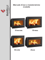 1
1
-
 2
2
-
 3
3
-
 4
4
-
 5
5
-
 6
6
-
 7
7
-
 8
8
-
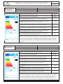 9
9
-
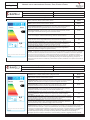 10
10
-
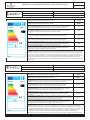 11
11
-
 12
12
-
 13
13
-
 14
14
-
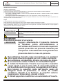 15
15
-
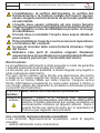 16
16
-
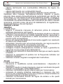 17
17
-
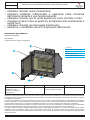 18
18
-
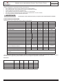 19
19
-
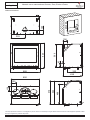 20
20
-
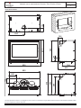 21
21
-
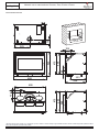 22
22
-
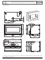 23
23
-
 24
24
-
 25
25
-
 26
26
-
 27
27
-
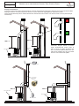 28
28
-
 29
29
-
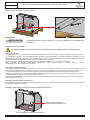 30
30
-
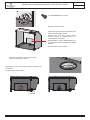 31
31
-
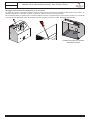 32
32
-
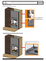 33
33
-
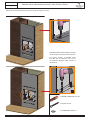 34
34
-
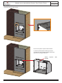 35
35
-
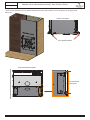 36
36
-
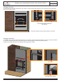 37
37
-
 38
38
-
 39
39
-
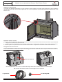 40
40
-
 41
41
-
 42
42
-
 43
43
-
 44
44
-
 45
45
-
 46
46
-
 47
47
-
 48
48
-
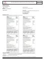 49
49
-
 50
50
-
 51
51
-
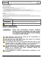 52
52
-
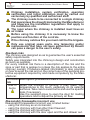 53
53
-
 54
54
-
 55
55
-
 56
56
-
 57
57
-
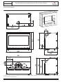 58
58
-
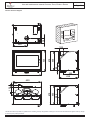 59
59
-
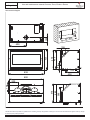 60
60
-
 61
61
-
 62
62
-
 63
63
-
 64
64
-
 65
65
-
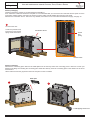 66
66
-
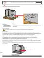 67
67
-
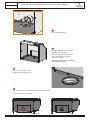 68
68
-
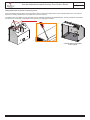 69
69
-
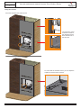 70
70
-
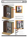 71
71
-
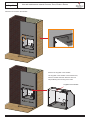 72
72
-
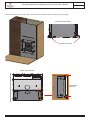 73
73
-
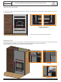 74
74
-
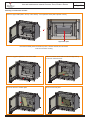 75
75
-
 76
76
-
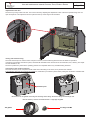 77
77
-
 78
78
-
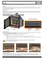 79
79
-
 80
80
-
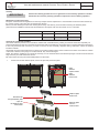 81
81
-
 82
82
-
 83
83
-
 84
84
-
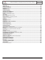 85
85
-
 86
86
-
 87
87
-
 88
88
-
 89
89
-
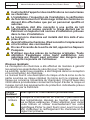 90
90
-
 91
91
-
 92
92
-
 93
93
-
 94
94
-
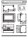 95
95
-
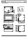 96
96
-
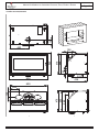 97
97
-
 98
98
-
 99
99
-
 100
100
-
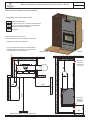 101
101
-
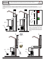 102
102
-
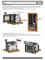 103
103
-
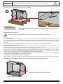 104
104
-
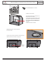 105
105
-
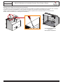 106
106
-
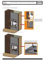 107
107
-
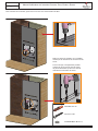 108
108
-
 109
109
-
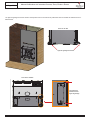 110
110
-
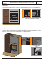 111
111
-
 112
112
-
 113
113
-
 114
114
-
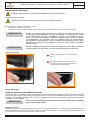 115
115
-
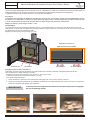 116
116
-
 117
117
-
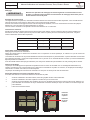 118
118
-
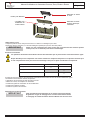 119
119
-
 120
120
-
 121
121
-
 122
122
-
 123
123
-
 124
124
-
 125
125
-
 126
126
-
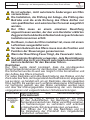 127
127
-
 128
128
-
 129
129
-
 130
130
-
 131
131
-
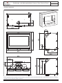 132
132
-
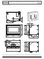 133
133
-
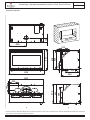 134
134
-
 135
135
-
 136
136
-
 137
137
-
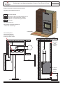 138
138
-
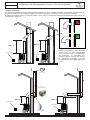 139
139
-
 140
140
-
 141
141
-
 142
142
-
 143
143
-
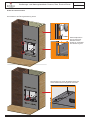 144
144
-
 145
145
-
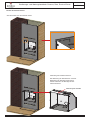 146
146
-
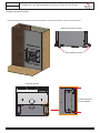 147
147
-
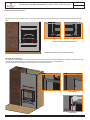 148
148
-
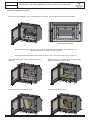 149
149
-
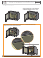 150
150
-
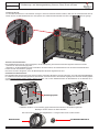 151
151
-
 152
152
-
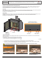 153
153
-
 154
154
-
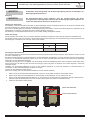 155
155
-
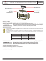 156
156
-
 157
157
-
 158
158
-
 159
159
-
 160
160
-
 161
161
-
 162
162
-
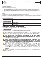 163
163
-
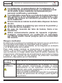 164
164
-
 165
165
-
 166
166
-
 167
167
-
 168
168
-
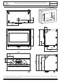 169
169
-
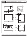 170
170
-
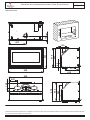 171
171
-
 172
172
-
 173
173
-
 174
174
-
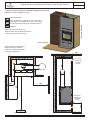 175
175
-
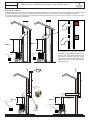 176
176
-
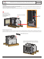 177
177
-
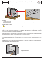 178
178
-
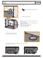 179
179
-
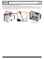 180
180
-
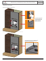 181
181
-
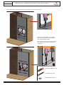 182
182
-
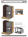 183
183
-
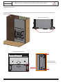 184
184
-
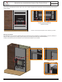 185
185
-
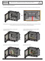 186
186
-
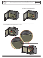 187
187
-
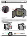 188
188
-
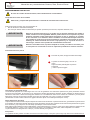 189
189
-
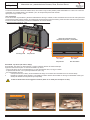 190
190
-
 191
191
-
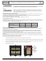 192
192
-
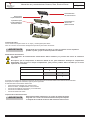 193
193
-
 194
194
-
 195
195
-
 196
196


Ravelli Ercole Use and Maintenance Manual
- Tipo
- Use and Maintenance Manual
- Este manual también es adecuado para
en otros idiomas
- français: Ravelli Ercole
- italiano: Ravelli Ercole
- Deutsch: Ravelli Ercole
Artículos relacionados
-
Ravelli Dual 9 Super Use and Maintenance Manual
-
-
-
-
-
-
-
-
-