
LIVI-ASLIVIMN-B-N LIVIPR
ITALY
MADE IN
W
A
R
R
A
N
T
Y
•
G
A
R
A
N
T
I
E
•
G
A
R
A
N
Z
I
A
•
G
A
R
A
N
T
I
A
•
G
A
R
A
N
T
I
E
•
G
A
R
A
N
T
I
E
•
Y
E
A
R
S
•
A
N
S
•
A
N
N
I
•
A
Ñ
O
S
•
A
N
O
•
J
A
H
R
E
•
3
English
Français
Italiano
Español
Português
Deutsch
Türk
VIDEO ENTRY KIT
LIVISTAR-B-N
INSTALLATION MANUAL
FG00902M07 - ver. 1 - 07/2017
English - Manual code FG00902M07 - ver. 1 07/2017 - The data and information shown in this manual are to be considered subject to change at any time and without the need for any advance warning.

2
1
A
B
C
212
161
29
60
83,5
83,5
B
A
C
Page 2 - Manual code FG00902M07 - ver. 1 07/2017 - The data and information shown in this manual are to be considered subject to change at any time and without the need for any advance warning.
Page 3 - Manual code FG00902M07 - ver. 1 07/2017 - The data and information shown in this manual are to be considered subject to change at any time and without the need for any advance warning.
General Notes
• Read the instructions carefully before beginning the installa-
tion and carry out the actions as specified by the manufacturer.
• The installation, programming, commissioning and maintenance
of the product must only be carried out by qualified technicians,
properly trained in compliance with the regulations in force, inclu-
ding health and safety measures and the disposal of packaging.
• The installer must ensure that the information for the user,
where there is any, is provided and delivered.
• Before carrying out any cleaning or maintenance operation,
disconnect the devices from the power supply.
• The equipment must only be used for the purpose for which
it was expressly designed.
• The manufacturer declines all liability for any damage as a
result of improper, incorrect or unreasonable use.
This product complies with the relevant directives in force.
Decommissioning and disposal. Dispose of the packaging
and the device at the end of its life cycle responsibly, in com-
pliance with the laws in force in the country where the product
is used. The recyclable components are marked with a symbol
and the material's ID marker.
THE DATA AND INFORMATION SHOWN IN THIS MANUAL ARE TO
BE CONSIDERED AS SUBJECT TO CHANGE AT ANY TIME AND
WITHOUT THE NEED FOR ANY ADVANCE WARNING. MEASURE-
MENTS, UNLESS OTHERWISE INDICATED, ARE IN MILLIMETRES.
LIVIMN-B-N
Wall-mounted installation
Unfasten the equipment from the metal support by letting it run
smoothly along it after you have pressed the plastic catch A.
Fix the metal support to the round Ø 60 mm back-box BA
or the rectangular 503 back-box BB BC using the screws
provided and paying attention to the (TOP) direction indication.
The box must be installed at an appropriate height for the user.
Avoid tightening the screws too much.
Once the connections are made, hook the video terminal onto the
metal support CD.To unhook the unit from the metal support
press the plastic catch and lift the terminal E.
For recessed installation refer to the recessing kit manual.

1
D E
F
G
LOCAL
BUS
LOCAL
BUS
A
B
CL.RES
M/S
LOCAL
SW1 SW3
SW4
M1
BUS
A
HCL.RES CL.RES CL.RES
XDV/304
1 2 3
IMASTER SLAVE
M/S M/S
Page 2 - Manual code FG00902M07 - ver. 1 07/2017 - The data and information shown in this manual are to be considered subject to change at any time and without the need for any advance warning.
Page 3 - Manual code FG00902M07 - ver. 1 07/2017 - The data and information shown in this manual are to be considered subject to change at any time and without the need for any advance warning.
Technical Features
Type
LIVIMN-B-N
Power supply by BUS (VDC)
15÷20
Consumption (mA max)
410
Consumption in stand by (mA)
<1
Local power supply (VDC)
16÷18
Consumption (mA max)
370
Consumption of single LED (mA)
(panic, disabling ring)
1
Storage temperature (°C)
-25 ÷ +70
Operating temperature (°C)
0 ÷ +35
IP Rating
20
Video standard
PAL/NTSC
Display colour TFT LCD (pollici)
7
Features
Terminal board FA
+Local power supply
–
BBUS line input
+Doorbell
–
AL Alarm Input
Selection of source of power supply (BUS/LOCAL) G
Separate power supply A
Power supply by BUS B
Selection of last receiver on the line (CL.RES) H
Master/slave selection (M/S) I
In the event of a call, the caller’s picture is displayed only on
those receivers configured as “MASTER”s.

Page 4 - Manual code FG00902M07 - ver. 1 07/2017 - The data and information shown in this manual are to be considered subject to change at any time and without the need for any advance warning.
Page 5 - Manual code FG00902M07 - ver. 1 07/2017 - The data and information shown in this manual are to be considered subject to change at any time and without the need for any advance warning.
Setting melodies
☞ All the programming stages described below must be carried out in sequence:
1- Going into Programming.
Press button 5 times in 5 secs.
A short beep confirms that you have entered programming mode.
2- Programming the melody associated with a call from the entry panel.
To listen to the melodies in sequence, press key .
To select the melody and exit programming, press key .
To select the melody and continue with programming, press key .
3- Programming the melody associated with a call from the front door.
To listen to the melodies in sequence, press key .
To select the melody and exit programming, press key .
To select the melody and continue with programming, press key .
4- Programming the number of rings for the call.
Press key as many times as you want it to ring (from 1 to 6 rings). Three seconds after the last press of the key the call selected for
the chosen number of rings will be played back.
To exit programming, press key .
☞ See the entry panel documentation for call programming.

A
43,5
45
7,5 57
70
106
A
B
64,5
70
145
43,5
45
7,5 57
70
106
A
B
64,5
70
145
M2M1
+–
AB
Page 4 - Manual code FG00902M07 - ver. 1 07/2017 - The data and information shown in this manual are to be considered subject to change at any time and without the need for any advance warning.
Page 5 - Manual code FG00902M07 - ver. 1 07/2017 - The data and information shown in this manual are to be considered subject to change at any time and without the need for any advance warning.
LIVI-AS
Installation
The power supplier must ALWAYS be installed horizontally. The
device can be installed on a DIN rail (EN 50022) in an appropriate
electric panel.
NOTE. Proper ventilation is required if the power supplier is in-
stalled in a metal container.
Technical features
Type
LIVI-AS
Power supply [V AC] 230
Max current demand [A AC]
0,2
Max energy dissipation [W] 10
Nominal power supply [V DC] 18
Nominal current demand [A DC]
1 for 1’
Nominal current demand [A DC] 0.5 for 3’
Storage temperature [°C] -25 ÷ +70
Operating temperature [°C]
0 ÷ +35
IP Rating [IP] 30
Features A
Terminal board A
~Mains
~
Terminal board B
–
+Power supply 18 VDC (*)
(*) The appliance is electronically protected against overloads
and short circuits.

A
C
500 mm
1080 mm
77¡
94¡
800 mm
500 mm
163,5 mm
43,5 mm
500 mm
1080 mm
77¡
94¡
800 mm
500 mm
163,5 mm
43,5 mm
B
D
135
99 30
3.5
6.5
243
207
135
99 30
3.5
6.5
243
207
Page 6 - Manual code FG00902M07 - ver. 1 07/2017 - The data and information shown in this manual are to be considered subject to change at any time and without the need for any advance warning.
Page 7 - Manual code FG00902M07 - ver. 1 07/2017 - The data and information shown in this manual are to be considered subject to change at any time and without the need for any advance warning.
LIVIPR
Wall Mounting
With the Allen wrench unscrew the blocking screws and remove
the plate A. Fix the given plugs and screw the entry panel B
at the desired height considering the position of the lens of the
camera C. Run the hose with the system conductors B.
Extract the plastic terminal cover and wire the connections D.
Once all the connections have been made, re-insert the terminal
covers.
For the installation of the accessories refer to the chapter “Button
module installation”. Perform the programming and adjustment
operations of the entry panel as described to the chapter “Pro-
gramming”. Install the front plate A.
Recessed Installation (optional)
Install the recessed box at the desired height considering the
position of the lens of the camera C, but in advance, run the
hose with the system conductors through one of the breaking
points F A.
H= 165 cm
(RECOMMENDED
HEIGHT)

G
I
F
1
2
A
B
A
B
J
H
E
Page 6 - Manual code FG00902M07 - ver. 1 07/2017 - The data and information shown in this manual are to be considered subject to change at any time and without the need for any advance warning.
Page 7 - Manual code FG00902M07 - ver. 1 07/2017 - The data and information shown in this manual are to be considered subject to change at any time and without the need for any advance warning.
During installation of the recessed box use the provided spacer to
prevent deformation F B. With the Allen wrench unscrew the
blocking screws and remove the entry panel plate A. Introduce
the cable connections in the special hole B and fix the entry
panel on the frame as shown in figure G; extract the plastic
terminal cover and wire the connections D.
Once the connections have been made and re-insert the terminal
covers. For the installation of the accessories refer to the chapter
“Button module installation”.
Perform the programming and adjustment operations of the entry
panel as described to the chapter “Programming”. Install the front
plate A.
Button module installation
Insert the button module as highlighted H paying special atten-
tion to the top to bottom orientation J.
Remove the glass and write the user names I, paying special
attention to the orientation of the glass J.

K
1
4
3
B
M1
BOUT
M2
SW3
PROG RESET
LED PROG
M1
BOUT
M2
SW3
PROG RESET
PROG
4
A3
B
E
L
Page 8 - Manual code FG00902M07 - ver. 1 07/2017 - The data and information shown in this manual are to be considered subject to change at any time and without the need for any advance warning.
Page 9 - Manual code FG00902M07 - ver. 1 07/2017 - The data and information shown in this manual are to be considered subject to change at any time and without the need for any advance warning.
Accessories K
LIVIPR-PS single button A,
LIVIPR-TP Wall roof B,
Recessed box LIVIPR-SI 3,
Recessed frame LIVIPR-CI d.
Technical features
Type LIVIPR
Power supply [V AC] 16-18
Consumption [mA] 250
Consumption in stand by [mA] 100
Storage temperature [°C] -25 ÷ +70
Operating temperature [°C) -15 ÷ +50
IP Rating [IP] 54
Standard video PAL/NTSC
Resolution [pixel]
680x512
Minimum lighting [LUX] 1
Features L
Terminal board A
BOUT Riser
+Power supply 16-18 VDC
–
Terminal board B
–Earth
Door lock release button (NA)
Solenoid lock
12 V 1 A max
–
PROG key C and PROG LED d
Programming key and LED (see 'Programming' paragraph).
The PROG LED can take on the following states:
O
On
Slow flashing
Quick flashing
Adjustments E
loudspeaker audio
microphone audio
Solenoid lock 1-10 s. (default 1 s)
Personalized labels, dimensions
53x13x0,3 mm 53x33x0,3 mm

SW3
PROG RESET
PROG
SW3
PROG RESET
PROG
>3’’
<6’’
B
4
5
SW3
PROG RESET
PROG
M1
BOUT
PROG
M2
M1
BOUT
PROG
M2
33 A
6
beep
A
7SW3
PROG RESET
PROG
<1’’
Page 8 - Manual code FG00902M07 - ver. 1 07/2017 - The data and information shown in this manual are to be considered subject to change at any time and without the need for any advance warning.
Page 9 - Manual code FG00902M07 - ver. 1 07/2017 - The data and information shown in this manual are to be considered subject to change at any time and without the need for any advance warning.
Programming
The kit is pre-configured to manage a single call originating from a single entry panel. One or more receivers answering the same call
can be added, by following the below “Call button programming” procedure.
Initial programming
Accessing programming. Press the PROG button A for at least 3 seconds and re-
lease it (within 6 seconds) as soon as the PROG LED comes on and the backlighting on
the buttons flashes as shown in figure B.
Programming button type. Press the first button on the entry panel in the position
marked 3/3A until the backlit LEDS stop flashing 4 and remain lit.
Programming the call keys. Press the door lock release and AUX2 5 buttons.
On the entry panel, press the call key to associate with the internal extension F: an
acoustic signal will confirm that the setting was stored. Hang up the receiver again.
Repeat the same operations for the other extensions.
Exiting programming. Briefly press the PROG button: the PROG LED goes o.
N.B. If no action is performed, the procedure will automatically end after 30 minutes.

5
2
SW3
PROG RESET
PROG
SW3
PROG RESET
PROG
<1’’
M1
BOUT
PROG
M2
SW3
PROG RESET
PROG
>3’’
<6’’
I
SW3
PROG RESET
PROG
>3’’
<6’’
A
6
34
beep
SW3
PROG RESET
PROG
G
M1
BOUT
PROG
M2
8
Page 10 - Manual code FG00902M07 - ver. 1 07/2017 - The data and information shown in this manual are to be considered subject to change at any time and without the need for any advance warning.
Page 11 - Manual code FG00902M07 - ver. 1 07/2017 - The data and information shown in this manual are to be considered subject to change at any time and without the need for any advance warning.
Reprogramming procedure
Accessing programming. Press the PROG button A for at least 3 seconds and re-
lease it (within 6 seconds) as soon as the PROG LED flashes and the backlighting on
the buttons comes on as shown in figure B.
Programming the call keys. Press the door lock release and AUX2 3 buttons.
On the entry panel, press the call key to associate with the internal extension 4: an
acoustic signal will confirm that the setting was stored. Hang up the receiver again.
Repeat the same operations for the other extensions.
Exiting programming. Briefly press the PROG button E: the PROG LED goes o. N.B.
If no action is performed, the procedure will automatically end after 30 minutes.
Programming button type. At the “Programming Call Buttons” stage, press the PROG
button F for at least 3 seconds and release it (within 6 seconds) as soon as the PROG
LED comes on and the backlighting on the buttons flashes as shown in figure G ,
entring the “Programming button type” procedure.
Press the first button on the entry panel in the position marked H until the backlit LEDS
stop flashing I and remain lit.
At the end, to exit programming, briefly press the PROG button E : the PROG LED goes
o. If no action is performed, the procedure will automatically end after 30 minutes.

SW3
PROG RESET
PROG
>8’’
<11’’
A
SW3
PROG RESET
PROG
M1
BOUT
SW3
PROG RESET
PROG
M2
2
3
4
3 beep
<1’’
M1
BOUT
SW3
PROG
RESET
PROG
M2
M1
BOUT
SW3
PROG
RESET
PROG
M2
1
2
Page 10 - Manual code FG00902M07 - ver. 1 07/2017 - The data and information shown in this manual are to be considered subject to change at any time and without the need for any advance warning.
Page 11 - Manual code FG00902M07 - ver. 1 07/2017 - The data and information shown in this manual are to be considered subject to change at any time and without the need for any advance warning.
Programming an intercom group
y Programming an intercommunicating group must be carried out AFTER assigning the call key to all of the receivers.
Assigning intercommunicating groups
With the SW3 jumper inserted, press the PROG key for at least 8 seconds and release
it (within 11 seconds) 1 as soon as the PROG LED flashes and the key back lighting
comes on 2.
To enable the intercom function, go to the receiver that you want to programme, and
press the intercom call key you want to call from: a beep will sound to show that
programming has taken place 3. Repeat for all receivers to be included in the inter-
communicating group.
At the end, briefly press the PROG key 4.
NOTE: If no action is performed, the procedure will end automatically after 30
minutes.
y Once a receiver has been included in an intercommunicating group by as-
signing the intercom call button, it cannot be excluded from this group. If you
want to change the intercom call button on a receiver which has already been
programmed as an intercommunicating receiver, or you want to add new receiv-
ers to the group, repeat the operations detailed under “Programming an inter-
communicating group”.
Disabling the intercom function
To deactivate the intercom function, you simply have to disconnect the SW3 jumper 1;
by doing this, programming of the intercom system is also inhibited.
To reactivate this function you must restore factory settings.

001CS2PLCO
+
BOUT
-
-
-
M1
+
–
M2
M2
A
001DC01LUXO
CL.RESM/S
001DC002AC
+
BOUT
-
+
-
M1
LOCAL
BUS
001DC002AC
2
2
2
2
2
2
2
2
001DC002AC
2
001DC002AC
2
2
2
001DC011AC
4
4
10
11
7
2
–
–
+
001DC011AC
CAME GATE
LIVIMN-B-N
LIVIPR
LIVI-AS
Page 12 - Manual code FG00902M07 - ver. 1 07/2017 - The data and information shown in this manual are to be considered subject to change at any time and without the need for any advance warning.
Page 13 - Manual code FG00902M07 - ver. 1 07/2017 - The data and information shown in this manual are to be considered subject to change at any time and without the need for any advance warning.
Connection examples

001CS2PLCO
+
BOUT
-
-
-
M2
+
–
M2
M1
001DC002AC
A
001DC01LUXO
CL.RESM/S
+
BOUT
-
+
-
M1
LOCAL
BUS
001DC01LUXO
CL.RESM/S
+
BOUT
-
+
-
M1
LOCAL
BUS
001DC01LUXO
CL.RESM/S
+
BOUT
-
+
-
M1
LOCAL
BUS
LIVIPR
LIVIMN-B-N
LIVIMN-B-N
LIVIMN-B-N
LIVI-AS
001DC002AC
2
2
2
2
2
2
2
2
001DC002AC
2
001DC002AC
2
2
2
001DC011AC
4
4
10
11
7
2
–
–
+
001DC011AC
CAME GATE
Page 12 - Manual code FG00902M07 - ver. 1 07/2017 - The data and information shown in this manual are to be considered subject to change at any time and without the need for any advance warning.
Page 13 - Manual code FG00902M07 - ver. 1 07/2017 - The data and information shown in this manual are to be considered subject to change at any time and without the need for any advance warning.

VCM/1D UTP CAT5
N° Master 1 1
N° Slave 4 1
VCM/1D UTP/CAT 5 2 x 2,5 mm2
La ≤100 m ≤30 m –
Lb ≤25 m – ≤60 m
La
La
N° Master N° Slave
Lb
LIVIPR
LIVI-AS
Page 14 - Manual code FG00902M07 - ver. 1 07/2017 - The data and information shown in this manual are to be considered subject to change at any time and without the need for any advance warning.
Page 15 - Manual code FG00902M07 - ver. 1 07/2017 - The data and information shown in this manual are to be considered subject to change at any time and without the need for any advance warning.
Distances

Page 14 - Manual code FG00902M07 - ver. 1 07/2017 - The data and information shown in this manual are to be considered subject to change at any time and without the need for any advance warning.
Page 15 - Manual code FG00902M07 - ver. 1 07/2017 - The data and information shown in this manual are to be considered subject to change at any time and without the need for any advance warning.

www.motostar-smarthome.com
contact@motostar-smarthome.com
è un marchio registrato di
Label Habitat SaS - 10 rue Léo Lagrange - 27950 Saint Marcel - France
English - Manual code FG00902M07 - ver. 1 07/2017 - The data and information shown in this manual are to be considered subject to change at any time and without the need for any advance warning.

LIVI-ASLIVIMN-B-N LIVIPR
ITALY
MADE IN
W
A
R
R
A
N
T
Y
•
G
A
R
A
N
T
I
E
•
G
A
R
A
N
Z
I
A
•
G
A
R
A
N
T
I
A
•
G
A
R
A
N
T
I
E
•
G
A
R
A
N
T
I
E
•
Y
E
A
R
S
•
A
N
S
•
A
N
N
I
•
A
Ñ
O
S
•
A
N
O
•
J
A
H
R
E
•
3
English
Français
Italiano
Español
Português
Deutsch
Türk
VIDEO KIT
LIVISTAR-B-N
MANUEL D'INSTALLATION
FG00902M07 - ver. 1 - 07/2017
Français - Code manuel FG00902M07 - vers. 1 07/2017 - Le contenu de ce manuel est susceptible de subir des modifications à tout moment et sans aucun préavis.

2
1
A
B
C
212
161
29
60
83,5
83,5
B
A
C
Page 2 - Code manuel FG00902M07 - vers. 1 07/2017 - Le contenu de ce manuel est susceptible de subir des modifications à tout moment et sans aucun préavis.
Instructions générales
• Lire attentivement les instructions, avant de commencer l'instal-
lation et eectuer les interventions comme indiqué par le fabricant.
• L'installation, la programmation, la mise en service et l'entre-
tien du produit ne doivent être eectués que par un personnel
technique qualifié et convenablement formé, conformément
aux normes en vigueur, y compris les dispositions concernant
la prévention des accidents et l'élimination des emballages.
• L’installateur doit veiller à ce que les informations pour l'usa-
ger, si prévues, soient présentes et remises.
• Avant d'eectuer toute opération de nettoyage ou d'entretien,
mettre les dispositifs hors tension.
• Les appareils doivent être utilisés uniquement aux fins pour
lesquels ils ont été conçus.
• Le fabricant ne saurait être tenu pour responsable des évent-
uels dommages dérivant d'une utilisation inadéquate, erronée
ou déraisonnable.
Le produit est conforme aux directives de référence en vigueur.
Démantèlement et élimination. Ne pas jeter les emballages et
l'appareil dans la nature à la fin du cycle de vie, mais veuillez les
éliminer conformément à la réglementation en vigueur dans le Pays
d'utilisation du produit. Les composants recyclables portent le sym-
bole et le sigle du matériau.
LES DONNÉES ET INFORMATIONS DE CE MANUEL SONT CONSI-
DÉRÉES COMME SUSCEPTIBLES DE MODIFICATIONS À TOUT MO-
MENT ET SANS PRÉAVIS. LES MESURES, SAUF AUTRES INDICA-
TIONS, SONT EXPRIMÉES EN MILLIMÈTRES.
LIVIMN-B-N
Installation murale
Décrocher l’appareil du support métallique, en le faisant glisser
sur lui-même après avoir appuyé sur la touche en plastique A.
Fixer le support métallique au boîtier à encastrer rond Ø 60 mm
BA ou au boîtier rectangulaire 503 BB BC à l’aide des
vis fournies et en respectant l’indication (TOP) . Le boîtier doit
être installé à une hauteur adéquate pour l’usager. Éviter de trop
serrer les vis. Après avoir eectué les branchements, fixer le ter-
minal vidéo au support métallique CD.
Pour décrocher l’appareil du support métallique, appuyer sur le
crochet en plastique et soulever le terminal E.

1
D E
F
G
LOCAL
BUS
LOCAL
BUS
A
B
CL.RES
M/S
LOCAL
SW1 SW3
SW4
M1
BUS
A
HCL.RES CL.RES CL.RES
XDV/304
1 2 3
IMASTER SLAVE
M/S M/S
Page 2 - Code manuel FG00902M07 - vers. 1 07/2017 - Le contenu de ce manuel est susceptible de subir des modifications à tout moment et sans aucun préavis.
Page 3 - Code manuel FG00902M07 - vers. 1 07/2017 - Le contenu de ce manuel est susceptible de subir des modifications à tout moment et sans aucun préavis.
Pour l’installation par encastrement, consulter la notice du kit
à encastrer.
Caractéristiques techniques
Type
LIVIMN-B-N
Alimentation : via BUS (VDC)
15÷20
Absorption (mA max)
410
Absorption en veille (mA)
<1
Alimentation locale (VDC)
16÷18
Absorption (mA max)
370
Absorption simple LED (mA)
(panique, désactivation sonnerie)
1
Température de stockage (°C)
-25 ÷ +70
Température de fonctionnement (°C)
0 ÷ +35
Indice IP
20
Standard vidéo
PAL/NTSC
Écran LCD TFT à couleurs (pouces)
7
Fonctions
Bornier FA
+Alimentation locale
–
BEntrée ligne BUS
+Appel palier
–
AL Entrée alarme
Sélection de la source d’alimentation (BUS/LOCAL) G
Alimentation séparée A
Alimentation : via BUS B
Sélection du dernier poste sur la ligne (CL.RES) H
Sélection Master/slave I
En cas d’appel, l’image de l’appelant ne s’ache que sur les
appareils dérivés configurés comme «MASTER».

Page 4 - Code manuel FG00902M07 - vers. 1 07/2017 - Le contenu de ce manuel est susceptible de subir des modifications à tout moment et sans aucun préavis.
Configuration des mélodies
☞ Eectuer, l’une après l’autre, toutes les phases de programmation décrites ci-après :
1- Entrée en mode programmation.
Appuyer 5 fois sur le bouton en 5 s.
Un signal sonore bref confirme l’entrée en mode programmation.
2- Programmation de la mélodie associée à l’appel provenant du poste externe.
Pour écouter les mélodies l’une après l’autre, appuyer sur la touche .
Pour sélectionner la mélodie et sortir de la programmation, appuyer sur la touche .
Pour sélectionner la mélodie et poursuivre la programmation, appuyer sur la touche .
3- Programmation de la mélodie associée à l’appel provenant du palier.
Pour écouter les mélodies l’une après l’autre, appuyer sur la touche .
Pour sélectionner la mélodie et sortir de la programmation, appuyer sur la touche .
Pour sélectionner la mélodie et poursuivre la programmation, appuyer sur la touche .
4- Programmation du nombre de sonneries de l’appel.
Appuyer sur la touche autant de fois que le nombre de sonneries souhaité (de 1 à 6 sonneries). Au bout de 3 secondes à compter
du dernier enfoncement de la touche, l’appel sélectionné sera reproduit selon le nombre de sonneries choisi.
Pour sortir du menu de programmation, appuyer sur la touche .
☞ Pour la programmation de l’appel, voir la documentation des postes externes.

A
43,5
45
7,5 57
70
106
A
B
64,5
70
145
43,5
45
7,5 57
70
106
A
B
64,5
70
145
M2M1
+–
AB
Page 4 - Code manuel FG00902M07 - vers. 1 07/2017 - Le contenu de ce manuel est susceptible de subir des modifications à tout moment et sans aucun préavis.
Page 5 - Code manuel FG00902M07 - vers. 1 07/2017 - Le contenu de ce manuel est susceptible de subir des modifications à tout moment et sans aucun préavis.
LIVI-AS
Installation
L’alimentateur doit TOUJOURS être installé à l’horizontale. L’ap-
pareil peut être installé sur rail DIN (EN 50022) dans un tableau
électrique prévu à cet eet.
NOTE. Pourvoir à une correcte aération au cas où l’alimentateur
serait installé dans un boîtier métallique.
Caractéristiques techniques
Type
LIVI-AS
Alimentation [V AC] 230
Courant absorbé max [A CA]
0,2
Puissance dissipée max [W] 10
Alimentation nominale [V CC] 18
Courant nominal absorbé [A CC]
1 pendant 1'
Courant nominal absorbé [A CC] 0,5 pendant 3'
Température de stockage [°C] -25 ÷ +70
Température de fonctionnement [°C]
0 ÷ +35
Indice IP [IP] 30
Fonctions A
Borniers A
~Secteur
~
Borniers B
–
+Alimentation 18 VDC (*)
(*) L’appareil est protégé électroniquement contre les surchar-
ges et les courts-circuits.

A
C
500 mm
1080 mm
77¡
94¡
800 mm
500 mm
163,5 mm
43,5 mm
500 mm
1080 mm
77¡
94¡
800 mm
500 mm
163,5 mm
43,5 mm
B
D
135
99 30
3.5
6.5
243
207
135
99 30
3.5
6.5
243
207
Page 6 - Code manuel FG00902M07 - vers. 1 07/2017 - Le contenu de ce manuel est susceptible de subir des modifications à tout moment et sans aucun préavis.
LIVIPR
Installation murale
À l’aide de la clé à six pans, dévisser les vis de blocage et retirer
la plaque A. Fixer les chevilles fournies et visser le poste exté-
rieur B à la hauteur souhaitée en tenant compte du positionne-
ment de l’objectif de la caméra C. Faire passer la canalisation
avec les conducteurs de l’installation B. Extraire le cache-borne
en plastique et eectuer les branchements D. Une fois les bran-
chement terminés, réinsérer les cache-bornes.
Pour le montage des accessoires, se référer au chapitre “Mon-
tage des modules bouton”.
Eectuer les opérations de programmation et les réglages du
poste extérieur comme décrit au chapitre “Programmation”.
Monter la plaque frontale A.
Installation à encastrer (en option)
Murer le boîtier à encastrer à la hauteur souhaitée en tenant
compte du positionnement de l’objectif de la caméra C et en
faisant préalablement passer la canalisation avec les conduc-
teurs de l’installation à travers un des points de rupture FA.
H= 165 cm
(HAUTEUR
CONSEILLÉE)

G
I
F
1
2
A
B
A
B
J
H
E
Page 6 - Code manuel FG00902M07 - vers. 1 07/2017 - Le contenu de ce manuel est susceptible de subir des modifications à tout moment et sans aucun préavis.
Page 7 - Code manuel FG00902M07 - vers. 1 07/2017 - Le contenu de ce manuel est susceptible de subir des modifications à tout moment et sans aucun préavis.
Lors de la mise en place du boîtier à encastrer, éviter de pos-
sibles déformations en utilisant la douille fournie et prévue à cet
eet FB.
À l’aide de la clé à six pans, dévisser les vis de blocage et retirer
la plaque du poste extérieur A.
Introduire les câbles de branchement dans le trou prévu à cet ef-
fet B, fixer le poste extérieur sur le cadre G; extraire le cache-
borne en plastique et eectuer les branchements D. Une fois
terminés les branchements et réinsérer les cache-bornes.
Pour le montage des accessoires, se référer au chapitre “Mon-
tage des modules bouton”. Eectuer les opérations de program-
mation et les réglages du poste extérieur comme décrit au cha-
pitre “Programmation”. Monter la plaque frontale A.
Montage des modules bouton
Insérer le module bouton H en faisant particulièrement attention
à l’orientation du haut vers le bas J.
Retirer la vitre et écrire les noms des usagers I, en faisant
particulièrement attention au sens d’application de la vitre J.

K
1
4
3
B
M1
BOUT
M2
SW3
PROG RESET
LED PROG
M1
BOUT
M2
SW3
PROG RESET
PROG
4
A3
B
E
L
Page 8 - Code manuel FG00902M07 - vers. 1 07/2017 - Le contenu de ce manuel est susceptible de subir des modifications à tout moment et sans aucun préavis.
Accessoires K
Bouton simple A LIVIPR-PS,
Visière de protection murale LIVIPR-TP B,
Boîtier à encastrer LIVIPR-SI 3,
Cadre pour encastrement LIVIPR-CI D.
53x13x0,3 mm 53x33x0,3 mm
Dimensions ètiquettes personnalisées
Caractéristiques techniques
Type LIVIPR
Alimentation [V AC] 16-18
Absorption [mA] 250
Absorption en veille [mA] 100
Température de stockage [°C] -25 ÷ +70
Température de fonctionnement [°C] -15 ÷ +50
Indice IP [IP] 54
Standard vidéo PAL/NTSC
Résolution [pixel]
680x512
Éclairage minimal [LUX] 1
Fonctions L
Borniers A
BOUT Montant
+Alimentation 16-18 VDC
–
Borniers B
–Masse
Bouton ouvre-porte (NO)
Gâche électrique
12 V 1 A max
–
Touche PROG C et LED PROG D
Touche et LED de programmation (voir paragraphe ‘Programma-
tion’).
La LED PROG peut prendre les états suivants :
Éteint
Allumé
Clignotement lent
Clignotement rapide
Réglages E
audio haut-parleur
audio micro
Gâche électrique 1÷10 s. (défaut 1 s)

SW3
PROG RESET
PROG
SW3
PROG RESET
PROG
>3’’
<6’’
B
4
5
SW3
PROG RESET
PROG
M1
BOUT
PROG
M2
M1
BOUT
PROG
M2
33 A
6
beep
A
7SW3
PROG RESET
PROG
<1’’
Page 9 - Code manuel FG00902M07 - vers. 1 07/2017 - Le contenu de ce manuel est susceptible de subir des modifications à tout moment et sans aucun préavis.
Page 8 - Code manuel FG00902M07 - vers. 1 07/2017 - Le contenu de ce manuel est susceptible de subir des modifications à tout moment et sans aucun préavis.
Programmation
Le kit est pré-configuré pour traiter un seul appel en provenance d’un seul poste externe. Il est possible d’ajouter un ou
plusieurs postes internes qui répondent au même appel à l’aide de la procédure “Programmation des touches d’appel”
au-dessous.
Première programmation
Entrée en Programmation. Appuyer pendant au moins 3 secondes sur la touche
PROG A et la relâcher (dans les 6 secondes) dès que la led PROG s’allume et que le
rétroéclairage des touches clignote comme illustré à la figure B.
Programmation du Type des touches. Appuyer sur la première touche du poste exté-
rieur dans la position indiquée 3/3A jusqu’à ce que les leds du rétroéclairage cessent
de clignoter 4 et restent allumées en permanence.
Programmation des touches d’appel. Appuyer sur les boutons ouvre-porte et
AUX2 5. Appuyer sur le poste extérieur sur la touche d’appel à associer au poste
intérieur F: suivra une indication sonore de mémorisation eectuée. Continuer en ré-
pétant les mêmes opérations pour tous les autres postes.
Sortie de la Programmation. Appuyer brièvement sur la touche PROG : la led PROG
est éteinte.
Emarque : en cas d’absence de toute manœuvre, la procédure s’arrête automatique-
ment après 30 minutes.

5
2
SW3
PROG RESET
PROG
SW3
PROG RESET
PROG
<1’’
M1
BOUT
PROG
M2
SW3
PROG RESET
PROG
>3’’
<6’’
I
SW3
PROG RESET
PROG
>3’’
<6’’
A
6
34
beep
SW3
PROG RESET
PROG
G
M1
BOUT
PROG
M2
8
Page 10 - Code manuel FG00902M07 - vers. 1 07/2017 - Le contenu de ce manuel est susceptible de subir des modifications à tout moment et sans aucun préavis.
Procédure de Reprogrammation
Entrée en Programmation. Appuyer pendant au moins 3 secondes sur la touche
PROG A et la relâcher (dans les 6 secondes) dès que la led PROG clignote et que le
rétroéclairage des touches s’allume comme illustré à la figure B.
Programmation des touches d’appel. Appuyer sur les boutons ouvre-porte et
AUX2 3. Appuyer sur le poste extérieur sur la touche d’appel à associer au poste
intérieur D: suivra une indication sonore de mémorisation eectuée. Continuer en ré-
pétant les mêmes opérations pour tous les autres postes.
Sortie de la Programmation. Appuyer brièvement sur la touche PROG E: la led PROG
est éteinte. Emarque : en cas d’absence de toute manœuvre, la procédure s’arrête
automatiquement après 30 minutes.
Programmation du Type des Touches. En phase de “Programmation des Touches
d’Appel”, appuyer pendant au moins 3 secondes sur la touche PROG F et la relâcher
(dans les 6 secondes) dès que la led PROG s’allume et que le rétroéclairage des touches
clignote comme illustré à la figure G, en entrant dans la procédure “Programmation
du Type des Touches”.
Appuyer sur la première touche du poste extérieur dans la position indiquée H jusqu’à
ce que les leds du rétroéclairage cessent de clignoter I et restent allumées en perma-
nence. À la fin, pour sortir de la programmation, appuyer de façon brève sur la touche
PROG E : la led PROG s’éteint.
En cas d’absence de toute manœuvre, la procédure s’arrête automatiquement après
30 minutes.

SW3
PROG RESET
PROG
>8’’
<11’’
A
SW3
PROG RESET
PROG
M1
BOUT
SW3
PROG RESET
PROG
M2
2
3
4
3 beep
<1’’
M1
BOUT
SW3
PROG
RESET
PROG
M2
M1
BOUT
SW3
PROG
RESET
PROG
M2
1
2
Page 11 - Code manuel FG00902M07 - vers. 1 07/2017 - Le contenu de ce manuel est susceptible de subir des modifications à tout moment et sans aucun préavis.
Programmation d’un groupe d’intercommunication
y La programmation du groupe intercommunicant doit être eectuée PAR LA SUITE à l’attribution de la touche d’appel à
tous les postes internes.
Attribution des groupes intercommunicants
Avec le cavalier SW3 activé, appuyer pendant au moins 8 s sur la touche PROG et la
relâcher (dans les 11 s) 1 dès que la led PROG clignote et que le rétroéclairage des
touches s’allume 2.
Pour activer le fonctionnement intercommunicant, se positionner sur le poste interne à
programmer et appuyer sur le bouton d’appel intercommunicant avec lequel l’appeler
: un signal sonore confirmera la programmation eective 3. Répéter ces mêmes opé-
rations pour tous les autres postes internes à inclure dans le groupe intercommunicant.
Au terme de ces opérations, appuyer brièvement sur la touche PROG 4.
REMARQUE. À défaut de toute autre action, la procédure termine automatique-
ment au bout de 30 minutes.
y Après avoir inclus un poste interne dans un groupe intercommunicant par
l’attribution de la touche d’appel intercommunicant, il n’est plus possible de l’ex-
clure du groupe en question. Pour modifier la touche d’appel intercommunicant
d’un poste interne déjà programmé comme intercommunicant, à savoir pour
ajouter au groupe de nouveaux postes internes, il sut de répéter la séquence
d’opérations décrite pour la « Programmation d’un groupe intercommunicant ».
Désactivation des groupes intercommunicants
Pour désactiver la fonction d’intercommunication, il sut de désactiver le cavalier SW3
1 pour pouvoir désactiver également la programmation du groupe intercommunicant.
Pour rétablir cette fonction, il sut de réinitialiser les paramètres d’usine.

001CS2PLCO
+
BOUT
-
-
-
M1
+
–
M2
M2
A
001DC01LUXO
CL.RESM/S
001DC002AC
+
BOUT
-
+
-
M1
LOCAL
BUS
001DC002AC
2
2
2
2
2
2
2
2
001DC002AC
2
001DC002AC
2
2
2
001DC011AC
4
4
10
11
7
2
–
–
+
001DC011AC
CAME GATE
LIVIMN-B-N
LIVIPR
LIVI-AS
Page 12 - Code manuel FG00902M07 - vers. 1 07/2017 - Le contenu de ce manuel est susceptible de subir des modifications à tout moment et sans aucun préavis.
Exemples de raccordement

001CS2PLCO
+
BOUT
-
-
-
M2
+
–
M2
M1
001DC002AC
A
001DC01LUXO
CL.RESM/S
+
BOUT
-
+
-
M1
LOCAL
BUS
001DC01LUXO
CL.RESM/S
+
BOUT
-
+
-
M1
LOCAL
BUS
001DC01LUXO
CL.RESM/S
+
BOUT
-
+
-
M1
LOCAL
BUS
LIVIPR
LIVIMN-B-N
LIVIMN-B-N
LIVIMN-B-N
LIVI-AS
001DC002AC
2
2
2
2
2
2
2
2
001DC002AC
2
001DC002AC
2
2
2
001DC011AC
4
4
10
11
7
2
–
–
+
001DC011AC
CAME GATE
Page 12 - Code manuel FG00902M07 - vers. 1 07/2017 - Le contenu de ce manuel est susceptible de subir des modifications à tout moment et sans aucun préavis.
Page 13 - Code manuel FG00902M07 - vers. 1 07/2017 - Le contenu de ce manuel est susceptible de subir des modifications à tout moment et sans aucun préavis.

VCM/1D UTP CAT5
N° Master 1 1
N° Slave 4 1
VCM/1D UTP/CAT 5 2 x 2,5 mm2
La ≤100 m ≤30 m –
Lb ≤25 m – ≤60 m
La
La
N° Master N° Slave
Lb
LIVIPR
LIVI-AS
Page 14 - Code manuel FG00902M07 - vers. 1 07/2017 - Le contenu de ce manuel est susceptible de subir des modifications à tout moment et sans aucun préavis.
Distances

Page 14 - Code manuel FG00902M07 - vers. 1 07/2017 - Le contenu de ce manuel est susceptible de subir des modifications à tout moment et sans aucun préavis.
Page 15 - Code manuel FG00902M07 - vers. 1 07/2017 - Le contenu de ce manuel est susceptible de subir des modifications à tout moment et sans aucun préavis.

www.motostar-smarthome.com
contact@motostar-smarthome.com
è un marchio registrato di
Label Habitat SaS - 10 rue Léo Lagrange - 27950 Saint Marcel - France
Français - Code manuel FG00902M07 - vers. 1 07/2017 - Le contenu de ce manuel est susceptible de subir des modifications à tout moment et sans aucun préavis.

LIVI-ASLIVIMN-B-N LIVIPR
ITALY
MADE IN
W
A
R
R
A
N
T
Y
•
G
A
R
A
N
T
I
E
•
G
A
R
A
N
Z
I
A
•
G
A
R
A
N
T
I
A
•
G
A
R
A
N
T
I
E
•
G
A
R
A
N
T
I
E
•
Y
E
A
R
S
•
A
N
S
•
A
N
N
I
•
A
Ñ
O
S
•
A
N
O
•
J
A
H
R
E
•
3
English
Français
Italiano
Español
Português
Deutsch
Türk
KIT VIDEOCITOFONICO
LIVISTAR-B-N
MANUALE DI INSTALLAZIONE
FG00902M07 - ver. 1 - 07/2017
Pag. 1 - Manuale FG00902M07 - ver. 1 - 07/2017 - I contenuti del manuale sono da ritenersi suscettibili di modifica in qualsiasi momento senza obbligo di preavviso.

2
1
A
B
C
212
161
29
60
83,5
83,5
B
A
C
Pag. 2 - Manuale FG00902M07 - ver. 1 - 07/2017 - I contenuti del manuale sono da ritenersi suscettibili di modifica in qualsiasi momento senza obbligo di preavviso.
Pag. 3 - Manuale FG00902M07 - ver. 1 - 07/2017 - I contenuti del manuale sono da ritenersi suscettibili di modifica in qualsiasi momento senza obbligo di preavviso.
Avvertenze generali
• Leggere attentamente le istruzioni prima di iniziare l’installazione
ed eseguire gli interventi come specificato dal costruttore,
• L’installazione, la programmazione, la messa in servizio e la ma-
nutenzione del prodotto deve essere eettuata soltanto da perso-
nale tecnico qualificato ed opportunamente addestrato nel rispetto
delle normative vigenti ivi comprese le osservanze sulla prevenzione
infortuni e lo smaltimento imballaggi,
• L’installatore deve assicurarsi che le informazioni per l’utente,
dove previste, siano presenti e vengano consegnate,
• Prima di eettuare qualunque operazione di pulizia o di manuten-
zione, togliere l’alimentazione ai dispositivi,
• Gli apparecchi dovranno essere destinati unicamente all’uso per
il quali sono stati espressamente concepiti,
• Il costruttore non può comunque essere considerato responsabile
per eventuali danni derivanti da usi impropri, erronei ed irragionevoli.
Il prodotto è conforme alle direttive di riferimento vigenti.
Dismissione e smaltimento. Non disperdere nell’ambiente l’im-
ballaggio e il dispositivo alla fine del ciclo di vita, ma smaltirli se-
guendo le norme vigenti nel paese di utilizzo del prodotto. I compo-
nenti riciclabili riportano simbolo e sigla del materiale.
I DATI E LE INFORMAZIONI INDICATE IN QUESTO MANUALE SONO
DA RITENERSI SUSCETTIBILI DI MODIFICA IN QUALSIASI MOMENTO
E SENZA OBBLIGO DI PREAVVISO. LE MISURE, SE NON DIVERSA-
MENTE INDICATO, SONO IN MILLIMETRI.
LIVIMN-B-N
Installazione a parete
Sganciare l’apparecchio dal supporto metallico, facendolo scor-
rere su di esso dopo aver premuto il pulsante plastico A.
Fissare il supporto metallico alla scatola d’incasso tonda Ø 60
mm BA oppure alla scatola rettangolare 503 BB BC uti-
lizzando le viti in dotazione e rispettando l’indicazione (TOP) .
La scatola deve essere installata ad un’altezza adeguata all’u-
tente. Evitare il serraggio eccessivo delle viti.
Eettuati i collegamenti, agganciare il videoterminale al supporto
metallico CD. Per sganciare l’apparecchio dal supporto metal-
lico premere il gancio plastico e sollevare il terminale E.
Per l’installazione da incasso fare riferimento al manuale del kit
da incasso.

1
D E
F
G
LOCAL
BUS
LOCAL
BUS
A
B
CL.RES
M/S
LOCAL
SW1 SW3
SW4
M1
BUS
A
HCL.RES CL.RES CL.RES
XDV/304
1 2 3
IMASTER SLAVE
M/S M/S
Pag. 2 - Manuale FG00902M07 - ver. 1 - 07/2017 - I contenuti del manuale sono da ritenersi suscettibili di modifica in qualsiasi momento senza obbligo di preavviso.
Pag. 3 - Manuale FG00902M07 - ver. 1 - 07/2017 - I contenuti del manuale sono da ritenersi suscettibili di modifica in qualsiasi momento senza obbligo di preavviso.
Caratteristiche tecniche
Tipo
LIVIMN-B-N
Alimentazione da BUS (VDC) 15÷20
Assorbimento (mA max)
410
Assorbimento in stand by (mA)
<1
Alimentazione locale (VDC) 16÷18
Assorbimento (mA max)
370
Assorbimento singolo LED (mA)
(panico, esclusione suoneria) 1
Temperatura di stoccaggio (°C) -25 ÷ +70
Temperatura di funzionamento (°C) 0 ÷ +35
Grado IP 20
Standard video
PAL/NTSC
Display LCD TFT a colori (pollici)
7
Funzioni
Morsettiera FA
+Alimentazione locale
–
BIngresso linea BUS
+Chiamata pianerottolo
–
AL Ingresso allarme
Selezione della sorgente di alimentazione (BUS/LOCAL) G
Alimentazione separata A
Alimentazione da BUS B
Selezione dell’ultimo derivato sulla linea (CL.RES) H
Selezione master/slave (M/S) I
In caso di chiamata, l’immagine del chiamante viene visualizzata
solo nei derivati configurati come “MASTER”.

Pag. 4 - Manuale FG00902M07 - ver. 1 - 07/2017 - I contenuti del manuale sono da ritenersi suscettibili di modifica in qualsiasi momento senza obbligo di preavviso.
Pag. 5 - Manuale FG00902M07 - ver. 1 - 07/2017 - I contenuti del manuale sono da ritenersi suscettibili di modifica in qualsiasi momento senza obbligo di preavviso.
Configurazione melodie
☞ Bisogna eseguire, in successione, tutte le fasi di programmazione descritte di seguito:
1- Ingresso in Programmazione.
Premere per 5 volte il pulsante entro 5 s.
Un breve segnale acustico conferma l’ingresso in programmazione.
2- Programmazione della melodia associata alla chiamata dal posto esterno.
Per ascoltare in sequenza le melodie premere il tasto .
Per selezionare la melodia ed uscire dalla programmazione premere il tasto .
Per selezionare la melodia e proseguire con la programmazione premere il tasto .
3- Programmazione della melodia associata alla chiamata dal pianerottolo.
Per ascoltare in sequenza le melodie premere il tasto .
Per selezionare la melodia ed uscire dalla programmazione premere il tasto
Per selezionare la melodia e proseguire con la programmazione premere il tasto .
4- Programmazione del numero di squilli di chiamata.
Premere il tasto tante volte quanti sono gli squilli desiderati (da 1 a 6 squilli). Dopo 3 secondi dall’ultima pressione del tasto verrà
riprodotta la chiamata selezionata per il numero di squilli prescelto.
Per uscire dalla programmazione premere il tasto .
☞ Per la programmazione della chiamata, vedere la documentazione dei posti esterni.

A
43,5
45
7,5 57
70
106
A
B
64,5
70
145
43,5
45
7,5 57
70
106
A
B
64,5
70
145
M2M1
+–
AB
Pag. 4 - Manuale FG00902M07 - ver. 1 - 07/2017 - I contenuti del manuale sono da ritenersi suscettibili di modifica in qualsiasi momento senza obbligo di preavviso.
Pag. 5 - Manuale FG00902M07 - ver. 1 - 07/2017 - I contenuti del manuale sono da ritenersi suscettibili di modifica in qualsiasi momento senza obbligo di preavviso.
LIVI-AS
Installazione
L’alimentatore deve essere installato SEMPRE in orizzontale.
L’apparecchio è installabile su guida DIN (EN 50022) in un appo-
sito quadro elettrico.
NOTA. Provvedere ad una corretta areazione nel caso l’alimenta-
tore venga installato in un contenitore metallico.
Caratteristiche tecniche
Tipo
LIVI-AS
Alimentazione [V AC] 230
Corrente assorbita max [A AC] 0,2
Potenza dissipata max [W]
10
Alimentazione nominale [V DC] 18
Corrente assorbita nominale [A DC] 1 per 1’
Corrente assorbita nominale [A DC]
0,5 per 3’
Temperatura di stoccaggio [°C] -25 ÷ +70
Temperatura di funzionamento [°C] 0 ÷ +35
Grado di protezione [IP]
30
Funzioni A
Morsettiera A
~Rete
~
Morsettiera B
–
+Alimentazione 18 VDC *
(*) L’apparecchio è protetto elettronicamente contro sovracca-
richi e cortocircuiti.

A
C
500 mm
1080 mm
77¡
94¡
800 mm
500 mm
163,5 mm
43,5 mm
500 mm
1080 mm
77¡
94¡
800 mm
500 mm
163,5 mm
43,5 mm
B
D
135
99 30
3.5
6.5
243
207
135
99 30
3.5
6.5
243
207
Pag. 6 - Manuale FG00902M07 - ver. 1 - 07/2017 - I contenuti del manuale sono da ritenersi suscettibili di modifica in qualsiasi momento senza obbligo di preavviso.
Pag. 7 - Manuale FG00902M07 - ver. 1 - 07/2017 - I contenuti del manuale sono da ritenersi suscettibili di modifica in qualsiasi momento senza obbligo di preavviso.
LIVIPR
Montaggio da parete
Tramite la chiave a brugola svitare le viti di bloccaggio e togliere
la placca A. Fissare i tasselli in dotazione e avvitare il posto
esterno B all’altezza desiderata tenendo conto del posiziona-
mento dell’obiettivo della telecamera C. Far passare la tubazio-
ne con i conduttori d’impianto B.
Estrarre il coprimorsetto in plastica ed eettuare i collegamenti
D. Una volta terminati i collegamenti reinserire i coprimorset-
ti. Per il montaggio degli accessori fare riferimento al capitolo
“Montaggio moduli pulsante”.
Eettuare le operazioni di programmazione e regolazioni del po-
sto esterno secondo quanto descritto al capitolo “Programmazio-
ne “. Montare la placca frontale A.
Installazione da incasso (opzionale)
Murare la scatola d’incasso all’altezza desiderata tenendo conto
del posizionamento dell’obiettivo della telecamera C, facendo
preventivamente passare la tubazione con i conduttori d’impianto
attraverso uno dei punti a rottura F A.
H= 165 cm
(ALTEZZA
CONSIGLIATA)

G
I
F
1
2
A
B
A
B
J
H
E
Pag. 6 - Manuale FG00902M07 - ver. 1 - 07/2017 - I contenuti del manuale sono da ritenersi suscettibili di modifica in qualsiasi momento senza obbligo di preavviso.
Pag. 7 - Manuale FG00902M07 - ver. 1 - 07/2017 - I contenuti del manuale sono da ritenersi suscettibili di modifica in qualsiasi momento senza obbligo di preavviso.
Nella messa in opera della scatola d’incasso si potranno evitare
possibili deformazioni utilizzando l’apposito distanziale in dota-
zione F B.
Tramite la chiave a brugola svitare le viti di bloccaggio e togliere
la placca del posto esterno A.
Introdurre i cavi di collegamento nell’apposito foro B e fissare il
posto esterno sulla cornice G; estrarre il coprimorsetto in plasti-
ca ed eettuare i collegamenti D. Una volta terminati i collega-
menti reinserire i coprimorsetti.
Per il montaggio degli accessori fare riferimento al capitolo
“Montaggio moduli pulsante”.
Eettuare le operazioni di programmazione e regolazioni del po-
sto esterno secondo quanto descritto nel capitolo “Programma-
zione”. Montare la placca frontale A.
Montaggio moduli pulsante
Inserire il modulo pulsante H facendo particolare attenzione
all’orientamento dall’alto verso al basso J.
Rimuovere il vetrino e scrivere i nominativi degli utenti come in-
dicato in figura I, facendo particolare attenzione al verso di
inserimento del vetrino J.

K
1
4
3
B
M1
BOUT
M2
SW3
PROG RESET
LED PROG
M1
BOUT
M2
SW3
PROG RESET
PROG
4
A3
B
E
L
Pag. 8 - Manuale FG00902M07 - ver. 1 - 07/2017 - I contenuti del manuale sono da ritenersi suscettibili di modifica in qualsiasi momento senza obbligo di preavviso.
Pag. 9 - Manuale FG00902M07 - ver. 1 - 07/2017 - I contenuti del manuale sono da ritenersi suscettibili di modifica in qualsiasi momento senza obbligo di preavviso.
Accessori K
Pulsante singolo LIVIPR-PS A,
Tettuccio da parete LIVIPR-TP B,
Scatola d’incasso LIVIPR-SI C,
Cornice da incasso LIVIPR-CI 4.
53x13x0,3 mm 53x33x0,3 mm
Dimensioni cartellini porta nome
Caratteristiche tecniche
Tipo LIVIPR
Alimentazione [V AC] 16-18
Assorbimento [mA] 250
Assorbimento in stand-by [mA] 100
Temperatura di stoccaggio [°C] -25 ÷ +70
Temperatura di funzionamento [°C) -15 ÷ +50
Grado di protezione [IP] 54
Standard video PAL/NTSC
Risoluzione [pixel]
680x512
Illuminazione minima [LUX] 1
Funzioni L
Morsettiera A
BOUT Montante
+Alimentazione 16-18 VDC
–
Morsettiera 2
–Massa
Pulsante apriporta (NA)
Elettroserratura
12 V 1 A max
–
Tasto PROG 3 e LED PROG 4
Tasto e LED di programmazione (vedi paragrafo ‘Programmazio-
ne’). Il LED PROG può assumere i seguenti stati:
Spento
Acceso
Lampeggio lento
Lampeggio veloce
Regolazioni 5
Audio altoparlante
audio microfono
elettroserratura 1÷10 s. (default 1 s)

SW3
PROG RESET
PROG
SW3
PROG RESET
PROG
>3’’
<6’’
B
4
5
SW3
PROG RESET
PROG
M1
BOUT
PROG
M2
M1
BOUT
PROG
M2
33 A
6
beep
A
7SW3
PROG RESET
PROG
<1’’
Pag. 8 - Manuale FG00902M07 - ver. 1 - 07/2017 - I contenuti del manuale sono da ritenersi suscettibili di modifica in qualsiasi momento senza obbligo di preavviso.
Pag. 9 - Manuale FG00902M07 - ver. 1 - 07/2017 - I contenuti del manuale sono da ritenersi suscettibili di modifica in qualsiasi momento senza obbligo di preavviso.
Programmazione
Il kit è pre-configurato per gestire una sola chiamata proveniente da un posto esterno. È possibile aggiungere uno o più
derivati interni che rispondono alla medesima chiamata seguendo la procedura “Programmazione dei tasti di chiamata”
di seguito descritta.
Prima Programmazione
Ingresso in Programmazione. Premere per almeno 3 secondi il tasto PROG A e
rilasciarlo (entro 6 secondi) non appena il LED PROG si accende e la retroilluminazione
dei tasti lampeggia come illustrato in figura B.
Programmazione del Tipo dei Tasti. Premere il primo tasto del posto esterno nella
posizione indicata 3/3A finchè i LED della retroilluminazione smetteranno di lampeg-
giare 4 rimanendo accesi.
Programmazione dei tasti chiamata. Premere i pulsanti apriporta ed AUX2
5. Premere sul posto esterno il tasto di chiamata da associare al derivato interno F:
seguirà un’indicazione acustica di avvenuta memorizzazione. Proseguire ripetendo le
stesse operazioni per tutti gli altri derivati.
Uscita dalla Programmazione. Premere brevemente il tasto PROG: il LED PROG si
spegne.
NOTA. In assenza di qualsiasi manovra, la procedura termina automaticamente dopo
30 minuti.

5
2
SW3
PROG RESET
PROG
SW3
PROG RESET
PROG
<1’’
M1
BOUT
PROG
M2
SW3
PROG RESET
PROG
>3’’
<6’’
I
SW3
PROG RESET
PROG
>3’’
<6’’
A
6
34
beep
SW3
PROG RESET
PROG
G
M1
BOUT
PROG
M2
8
Pag. 10 - Manuale FG00902M07 - ver. 1 - 07/2017 - I contenuti del manuale sono da ritenersi suscettibili di modifica in qualsiasi momento senza obbligo di preavviso.
Pag. 11 - Manuale FG00902M07 - ver. 1 - 07/2017 - I contenuti del manuale sono da ritenersi suscettibili di modifica in qualsiasi momento senza obbligo di preavviso.
Procedura di Riprogrammazione
Ingresso in Programmazione. Premere per almeno 3 secondi il tasto PROG A e
rilasciarlo (entro 6 secondi) non appena il LED PROG lampeggia e la retroilluminazione
dei tasti si accende come illustrato in figura B.
Programmazione dei tasti chiamata. Premere i pulsanti apriporta ed AUX2
3. Premere sul posto esterno il tasto di chiamata da associare al derivato interno 4:
seguirà un’indicazione acustica di avvenuta memorizzazione. Proseguire ripetendo le
stesse operazioni per tutti gli altri derivati.
Uscita dalla Programmazione. Premere brevemente il tasto PROG 5: il LED PROG si
spegne. NOTA. In assenza di qualsiasi manovra, la procedura termina automaticamente
dopo 30 minuti.
Programmazione del Tipo dei Tasti. In fase di “Programmazione dei Tasti di Chia-
mata”, premere per almeno 3 secondi il tasto PROG 6 e rilasciarlo (entro 6 secondi)
non appena il LED PROG si accende e la retroilluminazione dei tasti lampeggia come
illustrato in figura G, entrando nella procedura “Programmazione del Tipo dei Tasti”.
Premere il primo tasto del posto esterno nella posizione indicata H finchè i LED della
retroilluminazione smetteranno di lampeggiare I rimanendo accesi.
Al termine, per uscire dalla programmazione, premere brevemente il tasto PROG E: il
LED PROG si spegne. In assenza di qualsiasi manovra, la procedura termina automati-
camente dopo 30 minuti.

SW3
PROG RESET
PROG
>8’’
<11’’
A
SW3
PROG RESET
PROG
M1
BOUT
SW3
PROG RESET
PROG
M2
2
3
4
3 beep
<1’’
M1
BOUT
SW3
PROG
RESET
PROG
M2
M1
BOUT
SW3
PROG
RESET
PROG
M2
1
2
Pag. 10 - Manuale FG00902M07 - ver. 1 - 07/2017 - I contenuti del manuale sono da ritenersi suscettibili di modifica in qualsiasi momento senza obbligo di preavviso.
Pag. 11 - Manuale FG00902M07 - ver. 1 - 07/2017 - I contenuti del manuale sono da ritenersi suscettibili di modifica in qualsiasi momento senza obbligo di preavviso.
Programmazione di un gruppo intercomunicante
y La programmazione del gruppo intercomunicante deve essere eettuata SUCCESSIVAMENTE all’assegnazione a tutti i
derivati interni del tasto di chiamata.
Assegnazione dei gruppi intercomunicanti
Con il jumper SW3 inserito, premere per almeno 8 s il tasto PROG e rilasciarlo (entro 11
s) 1 non appena il led PROG lampeggia e la retroilluminazione dei tasti si accende 2.
Per abilitare il funzionamento intercomunicante posizionarsi sul derivato interno che si
vuole programmare e premere il pulsante di chiamata intercomunicante, con il quale lo
si desidera chiamare: seguirà un’indicazione acustica di avvenuta programmazione 3.
Proseguire ripetendo le stesse operazioni per tutti gli altri derivati interni da includere
nel gruppo intercomunicante.
Al termine, premere brevemente il tasto PROG 4.
NOTA. In assenza di qualsiasi manovra, la procedura termina automaticamente
dopo 30 minuti.
y Una volta che un derivato interno è stato incluso in un gruppo intercomuni-
cante mediante l’assegnazione del tasto di chiamata intercomunicante, non è
più possibile escluderlo dal gruppo medesimo. Qualora invece si voglia cambiare
il tasto di chiamata intercomunicante di un derivato interno già programmato
come intercomunicante ovvero aggiungere al gruppo nuovi derivati interni, è
suciente ripetere la sequenza di operazioni descritta per “Programmazione di
un gruppo intercomunicante”.
Disabilitazione dei gruppi intercomunicanti
Per disabilitare la funzione intercomunicante è suciente disinserire il jumper SW3
1; in questo modo si inibisce anche la programmazione del gruppo intercomunicante.
Per riabilitare la funzione medesima è necessario ripristinare il default di fabbrica.

001CS2PLCO
+
BOUT
-
-
-
M1
+
–
M2
M2
A
001DC01LUXO
CL.RESM/S
001DC002AC
+
BOUT
-
+
-
M1
LOCAL
BUS
001DC002AC
2
2
2
2
2
2
2
2
001DC002AC
2
001DC002AC
2
2
2
001DC011AC
4
4
10
11
7
2
–
–
+
001DC011AC
CAME GATE
LIVIMN-B-N
LIVIPR
LIVI-AS
Pag. 12 - Manuale FG00902M07 - ver. 1 - 07/2017 - I contenuti del manuale sono da ritenersi suscettibili di modifica in qualsiasi momento senza obbligo di preavviso.
Pag. 13 - Manuale FG00902M07 - ver. 1 - 07/2017 - I contenuti del manuale sono da ritenersi suscettibili di modifica in qualsiasi momento senza obbligo di preavviso.
Esempi di collegamento

001CS2PLCO
+
BOUT
-
-
-
M2
+
–
M2
M1
001DC002AC
A
001DC01LUXO
CL.RESM/S
+
BOUT
-
+
-
M1
LOCAL
BUS
001DC01LUXO
CL.RESM/S
+
BOUT
-
+
-
M1
LOCAL
BUS
001DC01LUXO
CL.RESM/S
+
BOUT
-
+
-
M1
LOCAL
BUS
LIVIPR
LIVIMN-B-N
LIVIMN-B-N
LIVIMN-B-N
LIVI-AS
001DC002AC
2
2
2
2
2
2
2
2
001DC002AC
2
001DC002AC
2
2
2
001DC011AC
4
4
10
11
7
2
–
–
+
001DC011AC
CAME GATE
Pag. 12 - Manuale FG00902M07 - ver. 1 - 07/2017 - I contenuti del manuale sono da ritenersi suscettibili di modifica in qualsiasi momento senza obbligo di preavviso.
Pag. 13 - Manuale FG00902M07 - ver. 1 - 07/2017 - I contenuti del manuale sono da ritenersi suscettibili di modifica in qualsiasi momento senza obbligo di preavviso.

VCM/1D UTP CAT5
N° Master 1 1
N° Slave 4 1
VCM/1D UTP/CAT 5 2 x 2,5 mm2
La ≤100 m ≤30 m –
Lb ≤25 m – ≤60 m
La
La
N° Master N° Slave
Lb
LIVIPR
LIVI-AS
Pag. 14 - Manuale FG00902M07 - ver. 1 - 07/2017 - I contenuti del manuale sono da ritenersi suscettibili di modifica in qualsiasi momento senza obbligo di preavviso.
Pag. 15 - Manuale FG00902M07 - ver. 1 - 07/2017 - I contenuti del manuale sono da ritenersi suscettibili di modifica in qualsiasi momento senza obbligo di preavviso.
Distanze

Pag. 14 - Manuale FG00902M07 - ver. 1 - 07/2017 - I contenuti del manuale sono da ritenersi suscettibili di modifica in qualsiasi momento senza obbligo di preavviso.
Pag. 15 - Manuale FG00902M07 - ver. 1 - 07/2017 - I contenuti del manuale sono da ritenersi suscettibili di modifica in qualsiasi momento senza obbligo di preavviso.

www.motostar-smarthome.com
contact@motostar-smarthome.com
è un marchio registrato di
Label Habitat SaS - 10 rue Léo Lagrange - 27950 Saint Marcel - France
Pag. 16 - Manuale FG00902M07 - ver. 1 - 07/2017 - I contenuti del manuale sono da ritenersi suscettibili di modifica in qualsiasi momento senza obbligo di preavviso.

LIVI-ASLIVIMN-B-N LIVIPR
ITALY
MADE IN
W
A
R
R
A
N
T
Y
•
G
A
R
A
N
T
I
E
•
G
A
R
A
N
Z
I
A
•
G
A
R
A
N
T
I
A
•
G
A
R
A
N
T
I
E
•
G
A
R
A
N
T
I
E
•
Y
E
A
R
S
•
A
N
S
•
A
N
N
I
•
A
Ñ
O
S
•
A
N
O
•
J
A
H
R
E
•
3
English
Français
Italiano
Español
Português
Deutsch
Türk
KIT DE VIDEO
LIVISTAR-B-N
MANUAL DE INSTALACIÓN
FG00902M07- ver. 1 - 07/2017
Pag. 1 -Codigo manual FG00902M07 - ver. 1 - 07/2017- Los contenidos del manual son susceptibles de modificación en cualquier momento y sin obligación de previo aviso.

2
1
A
B
C
212
161
29
60
83,5
83,5
B
A
C
Pag. 2 -Codigo manual FG00902M07 - ver. 1 - 07/2017- Los contenidos del manual son susceptibles de modificación en cualquier momento y sin obligación de previo aviso.
Advertencias generales
• Lea detenidamente las instrucciones antes de comenzar la
instalación y lleve a cabo las operaciones de la manera especi-
ficada por el fabricante.
• La instalación, la programación, la puesta en servicio y el man-
tenimiento del producto deben ser realizados únicamente por
personal técnico cualificado y debidamente formado de acuerdo
con las normas vigentes, incluidas las medidas de prevención de
accidentes y la eliminación del material de embalaje.
• El instalador debe asegurarse de que la información desti-
nada al usuario, cuando esté prevista, venga incluida y se en-
tregue al usuario.
• Antes de llevar a cabo cualquier tarea de limpieza o manteni-
miento, corte la alimentación de los dispositivos.
• Los aparatos deberán destinarse únicamente al uso para el
que están expresamente concebidos.
• En cualquier caso, el fabricante no podrá ser considerado re-
sponsable de posibles daños ocasionados por usos indebidos,
incorrectos y no razonables.
El producto es conforme a las directivas de referencia vigentes.
Desecho y eliminación. No libere al medio ambiente el embalaje
ni el dispositivo al final de su vida útil; elimínelos con arreglo a las
normas vigentes en el país de uso del producto. En los componen-
tes reciclables figuran el símbolo y la sigla del material.
LOS DATOS Y LA INFORMACIÓN QUE SE EXPONEN EN ESTE MA-
NUAL DEBEN CONSIDERARSE SUSCEPTIBLES DE MODIFICACIÓN
EN CUALQUIER MOMENTO Y SIN PREVIO AVISO. LAS MEDIDAS
ESTÁN EN MILÍMETROS SALVO QUE SE INDIQUE LO CONTRARIO.
LIVIMN-B-N
Instalación en superficie
Desenganche el aparato del soporte metálico, haciendo que se
deslice sobre él después de presionar el pulsador de plástico A.
Fije el soporte metálico a la caja de empotrar redonda Ø 60 mm
BA o a la caja rectangular 503 BB BC utilizando los tor-
nillos incluidos y respetando la indicación (TOP) . La caja debe
instalarse a una altura adecuada para el usuario. No apriete
demasiado los tornillos.
Una vez realizadas las conexiones, enganche el terminal de vídeo
al soporte metálico CD. Para desenganchar el aparato del so-

1
D E
F
G
LOCAL
BUS
LOCAL
BUS
A
B
CL.RES
M/S
LOCAL
SW1 SW3
SW4
M1
BUS
A
HCL.RES CL.RES CL.RES
XDV/304
1 2 3
IMASTER SLAVE
M/S M/S
Pag. 3 -Codigo manual FG00902M07 - ver. 1 - 07/2017- Los contenidos del manual son susceptibles de modificación en cualquier momento y sin obligación de previo aviso.
porte metálico, presione sobre el gancho de plástico y levante el
terminal E. Para la instalación empotrada, consulte el manual
del kit de empotrar.
Características técnicas
Tipo
LIVIMN-B-N
Alimentación por BUS (VCC)
15÷20
Absorción (mA máx.)
410
Absorción en stand-by (mA)
<1
Alimentación local (VCC)
16÷18
Absorción (mA máx.)
370
Absorción de cada LED (mA)
(pánico, deshabilitación del timbre)
1
Temperatura de almacenamiento (°C)
-25 ÷ +70
Temperatura de funcionamiento (°C)
0 ÷ +35
Grado IP
20
Estándar de vídeo
PAL/NTSC
Display LCD TFT en color (pulgadas)
7
Funciones
Bornera FA
+Alimentación local
–
BEntrada de línea BUS
+Llamada desde el rellano
–
AL Entrada de alarma
Selección de la fuente de alimentación (BUS/LOCAL) G
Alimentación separada (LOCAL) A
Alimentación por BUS B
Selección del último receptor de la línea (CL.RES) H
Selección master/slave (M/S) I
En caso de llamada, la imagen del llamante aparece solo en los
receptores configurados como “MASTER”.

Pag. 4 -Codigo manual FG00902M07 - ver. 1 - 07/2017- Los contenidos del manual son susceptibles de modificación en cualquier momento y sin obligación de previo aviso.
Configuración de las melodía
☞ Es necesario efectuar, en secuencia, todas las fases de programación que se describen a continuación:
1- Entrada en Programación.
Pulsar 5 veces el botón dentro de 5 s.
Una breve señal sonora confirma que se ha entrado en programación.
2 - Programación de la melodía asociada a la llamada desde la placa de calle.
Para escuchar, en secuencia, las melodías pulsar el botón .
Para seleccionar la melodía y salir de la programación pulsar el botón .
Para seleccionar la melodía y seguir adelante con la programación pulsar el botón .
3 - Programación de la melodía asociada a la llamada desde el rellano.
Para escuchar, en secuencia, las melodías pulsar el botón .
Para seleccionar la melodía y salir de la programación pulsar el botón .
Para seleccionar la melodía y seguir adelante con la programación pulsar el botón .
4 - Programación del número de timbres de llamada.
Pulsar el botón tantas veces cuantas son las repeticiones de timbre que se desea (entre 1 y 6 timbres). Transcurridos 3 segundos
desde la última presión del botón, es reproducida la llamada seleccionada el número de timbres que se han seleccionado.
Para salir de la programación, pulsar .
☞ Para la programación de la llamada, véase la documentación de las placas de calle.

A
43,5
45
7,5 57
70
106
A
B
64,5
70
145
43,5
45
7,5 57
70
106
A
B
64,5
70
145
M2M1
+–
AB
Pag. 5 -Codigo manual FG00902M07 - ver. 1 - 07/2017- Los contenidos del manual son susceptibles de modificación en cualquier momento y sin obligación de previo aviso.
LIVI-AS
Instalación
El alimentador debe instalarse SIEMPRE en horizontal. El aparato
puede instalarse en guía DIN (EN 50022) dentro de un cuadro
eléctrico adecuado.
NOTA. Garantice una correcta ventilación si se instala el alimen-
tador en una caja metálica.
Características técnicas
Tipo
LIVI-AS
Alimentación [V AC] 230
Máx. corriente absorbida [A CA] 0,2
Máx. potencia disipada [W] 10
Alimentación nominal [V DC] 18
Corriente absorbida nominal [A CC] 1 durante 1’
Corriente absorbida nominal [A CC] 0,5 durante 3’
Temperatura de almacena [°C] -25 ÷ +70
Temperatura de funcionamiento [°C] 0 ÷ +35
Grado de protección [IP] 30
Funciones A
Borneras A
~Red
~
Borneras B
–
+Alimentación 18 VCC (*)
(*) El aparato incluye protección electrónica contra sobrecargas
y cortocircuitos.

A
C
500 mm
1080 mm
77¡
94¡
800 mm
500 mm
163,5 mm
43,5 mm
500 mm
1080 mm
77¡
94¡
800 mm
500 mm
163,5 mm
43,5 mm
B
D
135
99 30
3.5
6.5
243
207
135
99 30
3.5
6.5
243
207
Pag. 6 -Codigo manual FG00902M07 - ver. 1 - 07/2017- Los contenidos del manual son susceptibles de modificación en cualquier momento y sin obligación de previo aviso.
LIVIPR
Instalación sobre pared
Usando la llave Allen, desenrosque los tornillos de fijación y quite
la placa A. Fije los tacos suministrados y atornille la placa ex-
terna B a la altura deseada, teniendo en cuenta la colocación
del objetivo de la cámara C. Pase el tubo con los conductores
de la instalación B.
Extraiga el cubreborne de plástico y realice las conexiones D.
Una vez concluidas las conexiones, vuelva a colocar los cubre-
bornes. Para el montaje de los accesorios, consulte el capítulo
“Montaje de los módulos de botón”.
Efectúe las operaciones de programación y ajustes de la placa
externa según se describe en el capítulo “Programación”. Monte
la placa frontal A.
Instalación empotrada (opcional)
Empotre la caja a la altura deseada teniendo en cuenta la colo-
cación del objetivo de la cámaraC, tras pasar el tubo con los
conductores de la instalación a través de uno de los orificios
precortados F A.
H= 165 cm
ALTURA
ACONSEJADA)

G
I
F
1
2
A
B
A
B
J
H
E
Pag. 7 -Codigo manual FG00902M07 - ver. 1 - 07/2017- Los contenidos del manual son susceptibles de modificación en cualquier momento y sin obligación de previo aviso.
Durante la instalación de la caja empotrable se podrán evitar po-
sibles deformaciones utilizando el distanciador suministrado F
B. Usando la llave Allen, desenrosque los tornillos de fijación y
quite la placa de la placa externa A.
Introduzca los cables de conexión por el orificio correspondiente
B y fíjela la placa externa contra el marco G; quite el cubrebor-
ne de plástico y efectúe las conexiones D.
Una vez concluidas las conexiones y vuelva a colocar los cubre-
bornes. Para el montaje de los accesorios, consulte el capítulo
“Montaje de los módulos de botón”.
Efectúe las operaciones de programación y ajustes de la placa
externa según se describe en el capítulo “Programación”. Monte
la placa frontal A.
Montaje de los módulos de botón
Introduzca el módulo de botón H, poniendo especial cuidado en
la orientación desde arriba hacia abajo J.
Extraiga el vidrio y escriba los nombres de los usuariosI, po-
niendo especial cuidado en el sentido de introducción del vidrio
J.

K
1
4
3
B
M1
BOUT
M2
SW3
PROG RESET
LED PROG
M1
BOUT
M2
SW3
PROG RESET
PROG
4
A3
B
E
L
Pag. 8 -Codigo manual FG00902M07 - ver. 1 - 07/2017- Los contenidos del manual son susceptibles de modificación en cualquier momento y sin obligación de previo aviso.
Accesorios K
Botón único A LIVIPR-PS,
Visera de superficie LIVIPR-TP B,
Caja empotrable LIVIPR-SI 3,
Marco empotrable LIVIPR-CI 4.
Características técnicas
Tipo LIVIPR
Alimentación [V AC] 16-18
Absorción [mA] 250
Absorción en stand-by [mA] 100
Temperatura de almacena [°C] -25 ÷ +70
Temperatura de funcionamiento [°C] -15 ÷ +50
Grado de protección [IP]
54
Standard video PAL/NTSC
Resolución [pixel]
680x512
Iluminación mínima [LUX] 1
Funciones L
Borneras A
BOUT Bajante
+Alimentación 16-18 VCC
–
Borneras B
–Masa
Botón abrepuerta (NA)
Cerradura eléctrica
12 V 1 A max
–
Tecla PROG C y LED PROG 4
Tecla y LED de programación (véase el apartado ‘Programación’).
El LED PROG puede asumir los siguientes estados:
Apagado
Encendido
Parpadeo lento
Parpadeo rápido
Regulaciones E
audio altavoz
audio micrófono
Cerradura eléctrica 1÷10 s. (por defecto1 s)
53x13x0,3 mm 53x33x0,3 mm
Letreros personalizados: Dimensiones

SW3
PROG RESET
PROG
SW3
PROG RESET
PROG
>3’’
<6’’
B
4
5
SW3
PROG RESET
PROG
M1
BOUT
PROG
M2
M1
BOUT
PROG
M2
33 A
6
beep
A
7SW3
PROG RESET
PROG
<1’’
Pag. 9 -Codigo manual FG00902M07 - ver. 1 - 07/2017- Los contenidos del manual son susceptibles de modificación en cualquier momento y sin obligación de previo aviso.
Programación
El kit viene preconfigurado para gestionar una sola llamada procedente de una única placa de calle. Pueden añadirse uno o varios re-
ceptores que responden a la misma llamada, siguiendo el procedimiento “Programación de las teclas de llamada” descrito después.
Primera programación
Entrada en la modalidad de Programación. Pulse durante al menos 3 s el botón
PROG A y suéltelo (antes de 6 s) en cuanto se encienda el led PROG y parpadee la
retroiluminación de los botones, tal y como se muestra en la figura B.
Programación del Tipo de los Botones. Pulse el primer botón de la placa exterior en
la posición indicada 3/3A hasta que los leds de la retroiluminación dejen de parpa-
dear 4 y permanezcan encendidos.
Programación de los botones de llamada. Pulse los botones abrepuerta y AUX2
5. Pulse en la placa exterior el botón de llamada que se desea asociar al derivado
interno F: seguirá una indicación acústica para confirmar la memorización. Repita las
mismas operaciones para todos los demás derivados.
Salida de la modalidad de Programación. Pulse brevemente el botón PROG: el led
PROG apagado. NOTA. Si no se efectúa ninguna operación, el proceso concluye auto-
máticamente tras 30 minutos.

5
2
SW3
PROG RESET
PROG
SW3
PROG RESET
PROG
<1’’
M1
BOUT
PROG
M2
SW3
PROG RESET
PROG
>3’’
<6’’
I
SW3
PROG RESET
PROG
>3’’
<6’’
A
6
34
beep
SW3
PROG RESET
PROG
G
M1
BOUT
PROG
M2
8
Pag. 10 -Codigo manual FG00902M07 - ver. 1 - 07/2017- Los contenidos del manual son susceptibles de modificación en cualquier momento y sin obligación de previo aviso.
Procedimiento de Reprogramación
Entrada en la modalidad de Programación. Pulse durante al menos 3 s el botón
PROG A y suéltelo (antes de 6 s) en cuanto parpadee el led PROG y se encienda la
retroiluminación de los botones, tal y como se muestra en la figura B.
Programación de los botones de llamada. Pulse los botones abrepuerta y AUX2
3. Pulse en la placa exterior el botón de llamada que se desea asociar al derivado
interno d: seguirá una indicación acústica para confirmar la memorización. Repita las
mismas operaciones para todos los demás derivados.
Salida de la modalidad de Programación. Pulse brevemente el botón PROG E: el
led PROG apagado. NOTA. Si no se efectúa ninguna operación, el proceso concluye
automáticamente tras 30 minutos.
Programación del Tipo de los Botones. En la fase de “Programación de los Botones
de Llamada”, pulse durante al menos 3 s el botón PROG F y suéltelo (antes de 6 s)
en cuanto se encienda el led PROG y parpadee la retroiluminación de los botones, tal y
como se muestra en la figura G; entrará en el proceso de “Programación del Tipo de
los Botones”. Pulse el primer botón de la placa exterior en la posición indicada H hasta
que los leds de la retroiluminación dejen de parpadear I permanezcan encendidos.
Al concluir, para salir de la modalidad de programación, pulse brevemente el botón
PROG E: led PROG apagado. Si no se efectúa ninguna operación, el proceso concluye
automáticamente tras 30 minutos.

SW3
PROG RESET
PROG
>8’’
<11’’
A
SW3
PROG RESET
PROG
M1
BOUT
SW3
PROG RESET
PROG
M2
2
3
4
3 beep
<1’’
M1
BOUT
SW3
PROG
RESET
PROG
M2
M1
BOUT
SW3
PROG
RESET
PROG
M2
1
2
Pag. 11 -Codigo manual FG00902M07 - ver. 1 - 07/2017- Los contenidos del manual son susceptibles de modificación en cualquier momento y sin obligación de previo aviso.
Programación de un grupo intercomunicante
y La programación del grupo intercomunicador se debe efectuar DESPUÉS de atribuir el pulsador de Llamada a todos los
receptores internos.
Atribución de los grupos intercomunicadores
Con el puente SW3 puesto, presionar durante por lo menos 8 s el pulsador PROG 1 y
soltarlo (dentro de 11 s) tan pronto parpadea el LED PROG y se enciende la retroilumi-
nación de los pulsadores, 2.
Para habilitar la intercomunicación, ir al receptor interno que se desea programar y
presionar el pulsador de Llamada de intercomunicación, con el cual lo se desea llamar:
una indicación sonora indica que la programación ha sido efectuada 3. Proseguir re-
pitiendo las mismas operaciones con todos los receptores internos que se desea incluir
en el grupo de intercomunicación.
Al final, pulsar brevemente el pulsador PROG 4.
NOTA: A falta de cualquier actividad, el proceso termina automáticamente trans-
curridos 30 minutos.
y Cuando un receptor interno ha sido incluido en un grupo intercomunicador,
por medio de la atribución del pulsador de Llamada intercomunicante, no se
puede excluirlo del grupo. Si en cambio se desea cambiar el pulsador de Llama-
da intercomunicante de un receptor interno ya programado como intercomuni-
cador o bien se desea añadir al grupo nuevos receptores internos, basta repetir
la secuencia de operaciones recién descritas para la "Programación de un grupo
intercomunicador".
Deshabilitación de la función intercomunicante
Para desactivar la función de intercomunicación es suficiente quitar el puente SW3 1;
de esta forma también se impide la programación del grupo intercomunicador.
Para reactivar la función es necesario restaurar los valores por defecto de fábrica.

001CS2PLCO
+
BOUT
-
-
-
M1
+
–
M2
M2
A
001DC01LUXO
CL.RESM/S
001DC002AC
+
BOUT
-
+
-
M1
LOCAL
BUS
001DC002AC
2
2
2
2
2
2
2
2
001DC002AC
2
001DC002AC
2
2
2
001DC011AC
4
4
10
11
7
2
–
–
+
001DC011AC
CAME GATE
LIVIMN-B-N
LIVIPR
LIVI-AS
Pag. 12 -Codigo manual FG00902M07 - ver. 1 - 07/2017- Los contenidos del manual son susceptibles de modificación en cualquier momento y sin obligación de previo aviso.
Ejemplos de conexión

001CS2PLCO
+
BOUT
-
-
-
M2
+
–
M2
M1
001DC002AC
A
001DC01LUXO
CL.RESM/S
+
BOUT
-
+
-
M1
LOCAL
BUS
001DC01LUXO
CL.RESM/S
+
BOUT
-
+
-
M1
LOCAL
BUS
001DC01LUXO
CL.RESM/S
+
BOUT
-
+
-
M1
LOCAL
BUS
LIVIPR
LIVIMN-B-N
LIVIMN-B-N
LIVIMN-B-N
LIVI-AS
001DC002AC
2
2
2
2
2
2
2
2
001DC002AC
2
001DC002AC
2
2
2
001DC011AC
4
4
10
11
7
2
–
–
+
001DC011AC
CAME GATE
Pag. 13 -Codigo manual FG00902M07 - ver. 1 - 07/2017- Los contenidos del manual son susceptibles de modificación en cualquier momento y sin obligación de previo aviso.

VCM/1D UTP CAT5
N° Master 1 1
N° Slave 4 1
VCM/1D UTP/CAT 5 2 x 2,5 mm2
La ≤100 m ≤30 m –
Lb ≤25 m – ≤60 m
La
La
N° Master N° Slave
Lb
LIVIPR
LIVI-AS
Pag. 14 -Codigo manual FG00902M07 - ver. 1 - 07/2017- Los contenidos del manual son susceptibles de modificación en cualquier momento y sin obligación de previo aviso.
Distancias

Pag. 15 -Codigo manual FG00902M07 - ver. 1 - 07/2017- Los contenidos del manual son susceptibles de modificación en cualquier momento y sin obligación de previo aviso.

www.motostar-smarthome.com
contact@motostar-smarthome.com
è un marchio registrato di
Label Habitat SaS - 10 rue Léo Lagrange - 27950 Saint Marcel - France
Pag. 16 -Codigo manual FG00902M07 - ver. 1 - 07/2017- Los contenidos del manual son susceptibles de modificación en cualquier momento y sin obligación de previo aviso.

LIVI-ASLIVIMN-B-N LIVIPR
ITALY
MADE IN
W
A
R
R
A
N
T
Y
•
G
A
R
A
N
T
I
E
•
G
A
R
A
N
Z
I
A
•
G
A
R
A
N
T
I
A
•
G
A
R
A
N
T
I
E
•
G
A
R
A
N
T
I
E
•
Y
E
A
R
S
•
A
N
S
•
A
N
N
I
•
A
Ñ
O
S
•
A
N
O
•
J
A
H
R
E
•
3
English
Français
Italiano
Español
Português
Deutsch
Türk
KIT VIDEO
LIVISTAR-B-N
MANUAL DE INSTALAÇÃO
FG00902M07- ver. 1 - 07/2017
Pag. 1-Código manual FG00902M07 - ver. 1 - 07/2017- O conteúdo deste manual deve ser considerado suscetível de alterações a qualquer momento e sem obrigação de aviso prévio.

2
1
A
B
C
212
161
29
60
83,5
83,5
B
A
C
Pag. 2-Código manual FG00902M07 - ver. 1 - 07/2017 - O conteúdo deste manual deve ser considerado suscetível de alterações a qualquer momento e sem obrigação de aviso prévio.
Avisos gerais
• Leia com atenção as instruções antes de iniciar a instalação
e realize as operações conforme o especificado pelo fabricante.
• A instalação, a programação, a colocação em serviço e a ma-
nutenção do produto devem ser realizadas apenas por pessoal
técnico qualificado e com formação adequada, cumprindo a
legislação aplicável inclusive as normas sobre a prevenção de
acidentes e a eliminação das embalagens.
• O instalador deve certificar-se de que as informações para o
utilizador, se previstas, estão presentes e são entregues.
• Antes de realizar qualquer operação de limpeza ou de manu-
tenção, desligue os aparelhos da rede de alimentação.
• Os aparelhos devem ser destinados unicamente ao uso para
o qual foram expressamente concebidos.
• O fabricante não pode, em caso algum, ser considerado
responsável por eventuais danos decorrentes de usos im-
próprios, errados e irracionais.
O produto está em conformidade com as diretivas de referência
em vigor.
Eliminação e desmantelamento. Não abandone a embala-
gem e o dispositivo no meio ambiente no fim do seu ciclo de
vida, mas elimine-os de acordo com as normas aplicáveis no
país em que o produto é utilizado. Os componentes recicláveis
apresentam símbolo e sigla do material.
OS DADOS E AS INFORMAÇÕES INDICADOS NESTE MANUAL
DEVEM SER CONSIDERADOS SUSCETÍVEIS DE ALTERAÇÃO, A
QUALQUER MOMENTO E SEM OBRIGAÇÃO DE AVISO PRÉVIO.
LIVIMN-B-N
Instalação de parede
Desencaixe o aparelho do suporte metálico, fazendo-o deslizar
sobre o mesmo após ter premido o botão de plástico A.
Fixe o suporte metálico na caixa de embutir redonda Ø 60 mm
BA ou na caixa retangular 503 BB BC, utilizando os pa-
rafusos fornecidos e respeitando a indicação (TOP) . A caixa
tem de ser instalada a uma altura adequada para o utilizador.
Evite apertar os parafusos excessivamente.
Após ter realizado as ligações, encaixe o terminal de vídeo no su-
porte metálico CD. Para soltar o aparelho do suporte metálico,

1
D E
F
G
LOCAL
BUS
LOCAL
BUS
A
B
CL.RES
M/S
LOCAL
SW1 SW3
SW4
M1
BUS
A
HCL.RES CL.RES CL.RES
XDV/304
1 2 3
IMASTER SLAVE
M/S M/S
Pag. 3-Código manual FG00902M07 - ver. 1 - 07/2017 - O conteúdo deste manual deve ser considerado suscetível de alterações a qualquer momento e sem obrigação de aviso prévio.
carregue no gancho plástico e levante o terminal E.
Para a instalação de embutir, consulte o manual do kit de em-
butir.
Características técnicas
Tipo
LIVIMN-B-N
Alimentação com BUS (VDC)
de 15 a 20
Consumo (mA máx.)
410
Consumo em stand by (mA)
<1
Alimentação local (VDC)
de 16 a 18
Consumo (mA máx.)
370
Consumo individual LED (mA)
(pânico, desativação dispositivo de som)
1
Temperatura de armazenagem (°C)
de -25 a +70
Temperatura de funcionamento (°C)
de 0 a +35
Grau IP
20
Standard vídeo
PAL/NTSC
Ecrã LCD TFT a cores (polegadas)
7
Funções
Régua de bornes FA
+Alimentação local
–
BEntrada linha BUS
+Chamada do patamar
–
AL Entrada alarme
Selecionar a fonte de alimentação (BUS/LOCAL) G
Alimentação separada A
Alimentação com BUS B
Selecionar o último derivado da linha (CL.RES) H
Selecionar o master/slave (M/S) I
Em caso de chamada, a imagem do chamador só é mostrada
nos derivados configurados como “MASTER”.

Pag. 4-Código manual FG00902M07 - ver. 1 - 07/2017 - O conteúdo deste manual deve ser considerado suscetível de alterações a qualquer momento e sem obrigação de aviso prévio.
Configuração de melodias
☞ É preciso executar uma após a outra, todas as fases de programação descritas a seguir:
1- Entrada na programação.
Prema 5 vezes o botão dentro de 5 s.
Um breve aviso sonoro confirma a entrada na programação.
2- Programação da melodia associada à chamada da placa botoneira.
Para escutar em sequência as melodias, prema a tecla .
Para selecionar a melodia e sair da programação, prema a tecla .
Para selecionar a melodia e continuar a programação, prema a tecla .
3- Programação da melodia associada à chamada do patamar.
Para escutar em sequência as melodias, prema a tecla .
Para selecionar a melodia e sair da programação, prema a tecla .
Para selecionar a melodia e continuar a programação, prema a tecla .
4- Programação do número de toques de chamada.
Prema a tecla de acordo com o número de toques desejados (de 1 a 6 toques). Após 3 segundos da última pressão da tecla será
reproduzida a chamada selecionada pelo número de toques escolhido.
Para sair da programação prema a tecla .
☞ Para programar a chamada, consulte a documentação das placas botoeira.

A
43,5
45
7,5 57
70
106
A
B
64,5
70
145
43,5
45
7,5 57
70
106
A
B
64,5
70
145
M2M1
+–
AB
Pag. 5-Código manual FG00902M07 - ver. 1 - 07/2017 - O conteúdo deste manual deve ser considerado suscetível de alterações a qualquer momento e sem obrigação de aviso prévio.
LIVI-AS
Instalação
O alimentador deve ser instalado SEMPRE na horizontal. O apa-
relho pode ser instalado na guia DIN (EN 50022), num quadro
eléctrico específico.
NOTA. Providencie uma ventilação adequada se o aparelho for
instalado numa caixa metálica.
Características técnicas
Tipo
LIVI-AS
Alimentação [V AC] 230
Corrente consumida máx. [A AC]
0,2
Potência dissipada máx. [W] 10
Alimentação nominal [V DC] 18
Corrente consumida nominal [A DC]
1 por 1’
Corrente consumida nominal [A DC] 0,5 por 3’
Temperatura de armazenagem [°C] -25 ÷ +70
Temperatura de funcionamento [°C]
0 ÷ +35
Grau IP [IP] 30
Funções A
Réguas de bornes A
~Rede
~
Réguas de bornes B
–
+Alimentação 18 VDC (*)
(*) O aparelho está protegido electronicamente contra sobre-
cargas e curtos-circuitos.

A
C
500 mm
1080 mm
77¡
94¡
800 mm
500 mm
163,5 mm
43,5 mm
500 mm
1080 mm
77¡
94¡
800 mm
500 mm
163,5 mm
43,5 mm
B
D
135
99 30
3.5
6.5
243
207
135
99 30
3.5
6.5
243
207
Pag. 6-Código manual FG00902M07 - ver. 1 - 07/2017 - O conteúdo deste manual deve ser considerado suscetível de alterações a qualquer momento e sem obrigação de aviso prévio.
LIVIPR
Instalação de parede
Com a chave allen desaperte os parafusos de fixação e extraia
a placa A.
Fixe as buchas fornecidas e aparafuse a placa botoneira B à al-
tura desejada tendo em conta a posição da objectiva da câmara
de vídeo C. Passe o tubo com os condutores da instalaçãoB.
Extraia a tampa do borne de plástico e faça as ligações D. Após
ter terminado as ligações reinsira as tampas dos bornes.
Para a montagem dos acessórios consulte o capítulo “Montagem
dos módulos botão”.
H= 165 cm
(ALTURA
RECOMENDADA)
Efectue as operações de programação e regulações da placa
botoneira segundo o descrito o capítulo “Programação”. Monte
a placa frontal A.
Instalação de embutir (opcional)
Monte a caixa de embutir na parede à altura desejada tendo em
conta a posição da objectiva da câmara de vídeo C e passando
previamente o tubo com os condutores de instalação através de
um dos pontos de ruptura F A.

G
I
F
1
2
A
B
A
B
J
H
E
Pag. 7-Código manual FG00902M07 - ver. 1 - 07/2017 - O conteúdo deste manual deve ser considerado suscetível de alterações a qualquer momento e sem obrigação de aviso prévio.
Ao instalar a caixa de embutir podem-se evitar possíveis defor-
mações utilizando o específico espaçador fornecido F B.
Com a chave allen desaperte os parafusos de fixação e extraia a
placa da placa botoneira A.
Introduzir os cabos de ligação no furo apropriado B e correção
a placa botoneira externa na moldura G; extrair a cobertura do
borne em plástico e efectuar as ligações D.
Após ter terminado as ligações e reinsira as tampas dos bornes.
Para a montagem dos acessórios consulte o capítulo “Montagem
dos módulos botão”.
Efectue as operações de programação e regulações da placa
botoneira segundo o descrito o capítulo “Programação”. Monte
a placa frontal A.
Montagem dos módulos botão
Insira o módulo botão H prestando particular atenção para o
orientar de cima para baixo J.
Remova o vidro e escreva os nomes dos utilizadores I, pres-
tando particular atenção à direcção de introdução do vidro J.

K
1
4
3
B
M1
BOUT
M2
SW3
PROG RESET
LED PROG
M1
BOUT
M2
SW3
PROG RESET
PROG
4
A3
B
E
L
Pag. 8-Código manual FG00902M07 - ver. 1 - 07/2017 - O conteúdo deste manual deve ser considerado suscetível de alterações a qualquer momento e sem obrigação de aviso prévio.
Acessórios K
Botão simples A LIVIPR-PS,
Tecto de parede LIVIPR-TP B,
Caixa de embutir LIVIPR-SI 3,
Moldura de embutir LIVIPR-CI 4.
Características técnicas
Tipo LIVIPR
Alimentação [V AC] 16-18
Consumo [mA] 250
Consumo em stand by [mA] 100
Temperatura de armazenagem [°C] -25 ÷ +70
Temperatura de funcionamento [°C) -15 ÷ +50
Grau IP [IP] 54
Standard vídeo
PAL/NTSC
Resolução [pixel] 680x512
Iluminação mínima [LUX] 1
Funções L
Réguas de bornes A
BOUT Coluna
+Alimentação 16-18 VDC
–
Réguas de bornes B
–Massa
Botão de abertura da porta (NA)
Fechadura eléctrica
12 V 1 A max
–
Tecla PROG C e LED PROG 4
Tecla e LED de programação (ver parágrafo ‘Programação’).
O LED PROG pode assumir os seguintes estados:
Apagado
Aceso
Intermitente lento
Intermitente rápido
Regulações E
áudio altifalante
áudio microfone
Fechadura eléctrica de 1 a 10 seg. (default 1 seg.)

SW3
PROG RESET
PROG
SW3
PROG RESET
PROG
>3’’
<6’’
B
4
5
SW3
PROG RESET
PROG
M1
BOUT
PROG
M2
M1
BOUT
PROG
M2
33 A
6
beep
A
7SW3
PROG RESET
PROG
<1’’
Pag. 9-Código manual FG00902M07 - ver. 1 - 07/2017 - O conteúdo deste manual deve ser considerado suscetível de alterações a qualquer momento e sem obrigação de aviso prévio.
Programação
O kit foi pré-configurado para gerir uma única chamada proveniente de uma única placa botoneira. É possível acrescentar
um ou mais derivados internos que respondam à mesma chamada seguindo o processo “Programação das teclas de
chamada” depois descrita.
Primeira programação
Entrada em Programação. Prima durante pelo menos 3 seg. a tecla PROG A e solte-
-a (dentro de 6 seg.) assim que o led PROG se acender e a retroiluminação das teclas
piscar, como ilustrado na figura B.
Programação do Tipo de Teclas. Prima a primeira tecla da placa botoneira na posição
indicada 3/3A até os leds da retroiluminação deixarem de piscar 4 ficando acesos.
Programação das teclas de chamada. Pulse prima os botões de abertura da porta
e AUX2 5. Prima na placa botoneira a tecla de chamada a associar ao derivado
interno F: segue uma indicação acústica de memorização efectuada. Repetindo as
mesmas operações para todos os outros derivados.
Sair da Programação. Prima brevemente a tecla PROG: o led PROG fora. NOTA. Na
ausência de qualquer operação, o processo termina automaticamente após 30 minutos.

5
2
SW3
PROG RESET
PROG
SW3
PROG RESET
PROG
<1’’
M1
BOUT
PROG
M2
SW3
PROG RESET
PROG
>3’’
<6’’
I
SW3
PROG RESET
PROG
>3’’
<6’’
A
6
34
beep
SW3
PROG RESET
PROG
G
M1
BOUT
PROG
M2
8
Pag. 10-Código manual FG00902M07 - ver. 1 - 07/2017 - O conteúdo deste manual deve ser considerado suscetível de alterações a qualquer momento e sem obrigação de aviso prévio.
Processo de Reprogramação
Entrada em Programação. Prima durante pelo menos 3 seg. a tecla PROG A e
solte-a (dentro de 6 seg.) assim que o led PROG piscar e a retroiluminação das teclas
se acender, como ilustrado na figura B.
Programação das teclas de chamada. Pulse prima os botões de abertura da porta
e AUX2 3. Prima na placa botoneira a tecla de chamada a associar ao derivado
interno 4: segue uma indicação acústica de memorização efectuada. Repetindo as
mesmas operações para todos os outros derivados.
Sair da Programação. Prima brevemente a tecla PROG E: o led PROG fora. NOTA. Na
ausência de qualquer operação, o processo termina automaticamente após 30 minutos.
Programação do Tipo de Teclas. Na fase de “Programação das teclas de Chamada”,
prima durante pelo menos 3 seg. a tecla PROG F e solte-a (dentro de 6 seg.) assim
que o led PROG se acender e a retroiluminação das teclas piscar, como ilustrado na
figura G, entrando deste modo no processo de “Programação do Tipo de Teclas”. Prima
a primeira tecla da placa botoneira na posição indicada H até os leds da retroilumina-
ção deixarem de piscar I ficando acesos.
No fim, para sair da programação, prima brevemente a tecla PROG E: led PROG apa-
gado. Na ausência de qualquer operação, o processo termina automaticamente após
30 minutos.

SW3
PROG RESET
PROG
>8’’
<11’’
A
SW3
PROG RESET
PROG
M1
BOUT
SW3
PROG RESET
PROG
M2
2
3
4
3 beep
<1’’
M1
BOUT
SW3
PROG
RESET
PROG
M2
M1
BOUT
SW3
PROG
RESET
PROG
M2
1
2
Pag. 11-Código manual FG00902M07 - ver. 1 - 07/2017 - O conteúdo deste manual deve ser considerado suscetível de alterações a qualquer momento e sem obrigação de aviso prévio.
Programação de um grupo de intercomunicação
y A programação do grupo intercomunicante deve ser feita DEPOIS da atribuição a todos os derivados internos da tecla
de chamada.
Atribuição dos grupos intercomunicantes
Com o jumper SW3 inserido, prema por ao menos 8 seg. a tecla PROG e solte-a
(dentro de 11 seg.) 1 assim que o LED PROG lampejar e a retroiluminação das teclas
acender 2.
Para habilitar o funcionamento intercomunicante, coloque-se no derivado interno que
queira programar e prema o botão de chamada intercomunicante, com o qual o deseja
chamar: um aviso sonoro indicará que a programação foi efetuada 3. Continue a re-
petir as mesmas operações para todos os demais derivados internos a serem incluídos
no grupo intercomunicável.
Ao terminar, prema brevemente a tecla PROG 4.
NOTA. Se nada for feito, o procedimento termina automaticamente depois de
30 minutos.
y Depois que um derivado interno foi incluído num grupo intercomunicante
com a atribuição da tecla de chamada intercomunicante, não será mais possível
excluí-lo desse mesmo grupo. Se desejar mudar o botão de chamada de um
derivado interno já programado como intercomunicante, ou seja, adicionar ao
grupo novos derivados internos, é suficiente repetir a sequência de operações
descrita para “Programação de um grupo intercomunicante”.
Desabilitação da função intercomunicável
Para desabilitar a função intercomunicante basta desligar o jumper SW3 1; deste
modo é inibida também a programação do grupo intercomunicante.
Para habilitar novamente esta mesma função é preciso retomar os padrões predefinidos
em fábrica.

001CS2PLCO
+
BOUT
-
-
-
M1
+
–
M2
M2
A
001DC01LUXO
CL.RESM/S
001DC002AC
+
BOUT
-
+
-
M1
LOCAL
BUS
001DC002AC
2
2
2
2
2
2
2
2
001DC002AC
2
001DC002AC
2
2
2
001DC011AC
4
4
10
11
7
2
–
–
+
001DC011AC
CAME GATE
LIVIMN-B-N
LIVIPR
LIVI-AS
Pag. 12-Código manual FG00902M07 - ver. 1 - 07/2017 - O conteúdo deste manual deve ser considerado suscetível de alterações a qualquer momento e sem obrigação de aviso prévio.
Exemplos de ligação

001CS2PLCO
+
BOUT
-
-
-
M2
+
–
M2
M1
001DC002AC
A
001DC01LUXO
CL.RESM/S
+
BOUT
-
+
-
M1
LOCAL
BUS
001DC01LUXO
CL.RESM/S
+
BOUT
-
+
-
M1
LOCAL
BUS
001DC01LUXO
CL.RESM/S
+
BOUT
-
+
-
M1
LOCAL
BUS
LIVIPR
LIVIMN-B-N
LIVIMN-B-N
LIVIMN-B-N
LIVI-AS
001DC002AC
2
2
2
2
2
2
2
2
001DC002AC
2
001DC002AC
2
2
2
001DC011AC
4
4
10
11
7
2
–
–
+
001DC011AC
CAME GATE
Pag. 13-Código manual FG00902M07 - ver. 1 - 07/2017 - O conteúdo deste manual deve ser considerado suscetível de alterações a qualquer momento e sem obrigação de aviso prévio.

VCM/1D UTP CAT5
N° Master 1 1
N° Slave 4 1
VCM/1D UTP/CAT 5 2 x 2,5 mm2
La ≤100 m ≤30 m –
Lb ≤25 m – ≤60 m
La
La
N° Master N° Slave
Lb
LIVIPR
LIVI-AS
Pag. 14-Código manual FG00902M07 - ver. 1 - 07/2017 - O conteúdo deste manual deve ser considerado suscetível de alterações a qualquer momento e sem obrigação de aviso prévio.
Distâncias

Pag. 15-Código manual FG00902M07 - ver. 1 - 07/2017 - O conteúdo deste manual deve ser considerado suscetível de alterações a qualquer momento e sem obrigação de aviso prévio.

www.motostar-smarthome.com
contact@motostar-smarthome.com
è un marchio registrato di
Label Habitat SaS - 10 rue Léo Lagrange - 27950 Saint Marcel - France
Pag. 16-Código manual FG00902M07 - ver. 1 - 07/2017- O conteúdo deste manual deve ser considerado suscetível de alterações a qualquer momento e sem obrigação de aviso prévio.

LIVI-ASLIVIMN-B-N LIVIPR
ITALY
MADE IN
W
A
R
R
A
N
T
Y
•
G
A
R
A
N
T
I
E
•
G
A
R
A
N
Z
I
A
•
G
A
R
A
N
T
I
A
•
G
A
R
A
N
T
I
E
•
G
A
R
A
N
T
I
E
•
Y
E
A
R
S
•
A
N
S
•
A
N
N
I
•
A
Ñ
O
S
•
A
N
O
•
J
A
H
R
E
•
3
English
Français
Italiano
Español
Português
Deutsch
Türk
VIDEO KIT
LIVISTAR-B-N
INSTALLATIONSANLEITUNG
FG00902M07- ver. 1 - 07/2017
Pag. 1 - Anleitung FG00902M07 - ver. 1 - 07/2017- Der Inhalt der Anleitung kann jederzeit ohne Vorankündigung geändert werden.

2
1
A
B
C
212
161
29
60
83,5
83,5
B
A
C
Pag. 2 - Anleitung FG00902M07 - ver. 1 - 07/2017- Der Inhalt der Anleitung kann jederzeit ohne Vorankündigung geändert werden.
Allgemeine Hinweise
• Lesen Sie aufmerksam die Anweisungen, bevor Sie mit dem
Einbau beginnen, und führen Sie die vom Hersteller genannten
Arbeiten aus.
• Die Installation, Programmierung, Inbetriebnahme und War-
tung des Produktes dürfen ausschließlich von qualifiziertem
und entsprechend geschultem Fachpersonal unter Einhaltung
der geltenden Normen, einschließlich der Unfallverhütungs-
und Abfallentsorgungsvorschriften, durchgeführt werden.
• Der Installateur muss sich vergewissern, dass die Informa-
tionen für den Nutzer, wo vorgesehen, vorhanden sind und
übergeben werden.
• Bevor Sie jegliche Reinigungs- oder Wartungsarbeiten vorneh-
men, trennen Sie die Geräte immer erst von der Stromversorgung.
• Die Geräte dürfen ausschließlich für den Zweck verwendet
werden, für den sie ausdrücklich konzipiert wurden.
• Der Hersteller übernimmt keinerlei Haftung für eventuelle
Schäden, die sich aus einem unsachgemäßen, falschen und/
oder unvernünftigen Gebrauch ergeben.
Das Produkt ist mit den geltenden Bezugsrichtlinien konform.
Stilllegung und Entsorgung. Das Verpackungsmaterial und
das Gerät müssen am Ende ihrer Lebensdauer gemäß den
Vorschriften des Bestimmungslandes ordnungsgemäß und
umweltgerecht entsorgt werden. Die wiederverwertbaren Ge-
räteteile sind mit einem Materialsymbol und -zeichen versehen.
DIE IN DIESER ANLEITUNG ENTHALTENEN DATEN UND INFOR-
MATIONEN KÖNNEN JEDERZEIT UND OHNE VORHERIGE AN-
KÜNDIGUNG GEÄNDERT WERDEN. DIE MASSANGABEN SIND,
WENN NICHT ANDERS ANGEGEBEN, IN MILLIMETERN.
LIVIMN-B-N
Wandmontage
Lösen Sie das Gerät von der Metallhalterung, indem Sie den
Kunststoknopf A drücken und es dann von der Halterung gleiten
lassen. Befestigen Sie die Metallhalterung am runden Unterputz-
gehäuse Ø 60mm B A oder am rechteckigen Gehäuse 503 B
B B C mithilfe der mitgelieferten Schrauben und unter Berück-
sichtigung der Angabe (TOP) . Das Wandgehäuse muss auf einer
für den Nutzer angemessenen Höhe montiert werden.
Ziehen Sie die Schrauben nicht zu fest an. Nach Anschluss

1
D E
F
G
LOCAL
BUS
LOCAL
BUS
A
B
CL.RES
M/S
LOCAL
SW1 SW3
SW4
M1
BUS
A
HCL.RES CL.RES CL.RES
XDV/304
1 2 3
IMASTER SLAVE
M/S M/S
Pag. 3 - Anleitung FG00902M07 - ver. 1 - 07/2017- Der Inhalt der Anleitung kann jederzeit ohne Vorankündigung geändert werden.
können Sie das Videoterminal in die
Metallhalterung einhängen
CD
. Um das Gerät aus der Metallhalterung zu entfernen, drücken
Sie auf den Kunststohaken und heben Sie das Terminal an
E
.
Für die Unterputzmontage siehe die Anleitung des Kits für die Un-
terputzmontage.
Technische Eigenschaften
Typ
LIVIMN-B-N
Versorgung über BUS (VDC)
15÷20
Stromaufnahme (mA max)
410
Stromaufnahme im Standby (mA)
<1
Lokale Versorgung (VDC)
16÷18
Stromaufnahme (mA max)
370
Spannungsversorgung einzelne LED (mA)
(Panik, Stummschaltung)
1
Lagertemperatur (°C)
-25 ÷ +70
Betriebstemperatur (°C)
0 ÷ +35
IP-Schutzgrad
20
Standard-Video
PAL/NTSC
TFT-Monitor mit LCD-Farbdisplay (Zoll)
7
Klemmleiste FA
+Lokale Spannungsversorgung
–
BEingang BUS-Leitung
+Treppenhaus-Anruf
–
AL Alarmeingang
Auswahl der Versorgungsquelle (BUS/LOCAL) G
Getrennte Stromversorgung A
Versorgung über BUS B
Auswahl der letzten Innensprechstelle (CL.RES) H
Auswahl Master/Slave (M/S) I
Bei einem Anruf wird das Bild des Anrufenden nur an den In-
nensprechstellen gezeigt, die als „MASTER“ konfiguriert sind.

Pag. 4 - Anleitung FG00902M07 - ver. 1 - 07/2017- Der Inhalt der Anleitung kann jederzeit ohne Vorankündigung geändert werden.
Klingeltöne einstellen
☞ Alle im Folgenden beschriebenen Schritte nacheinander durchführen:
1- Eingang im Programmiermodus.
Innerhalb von 5 Sek. 5 Mal die Taste drücken .
Ein kurzer Piepton bestätigt, dass der Eingang auf Programmiermodus geschaltet wurde.
2 - Programmierung des der anrufenden Außenstation zugeordneten Klingeltons.
Um die Melodien hintereinander abzuspielen, die Taste drücken.
Um die Melodie auszuwählen und aus dem Programmiermodus auszusteigen, die Taste drücken.
Um die Melodie auszuwählen und weitere Programmierungen vorzunehmen, die Taste drücken.
3- Programmierung des Klingeltons, der einen Anruf von der Etage anzeigt.
Um die Melodien hintereinander abzuspielen, die Taste drücken.
Um die Melodie auszuwählen und aus dem Programmiermodus auszusteigen, die Taste drücken.
Um die Melodie auszuwählen und weitere Programmierungen vorzunehmen, die Taste .
4- Programmierung der Anzahl der Klingelzeichen der Anrufe.
Die Taste so oft drücken, wie die Klingel läuten soll (1 bis 6 Klingelzeichen). 3 Sekunden nach dem letzten Druck der Taste wird der
Anruf mit der gewählten Anzahl von Klingelzeichen abgespielt.
Um aus dem Programmiermodus auszusteigen, die Taste drücken.
☞ Für die Anrufprogrammierung, siehe die Unterlagen der Außenstationen.

A
43,5
45
7,5 57
70
106
A
B
64,5
70
145
43,5
45
7,5 57
70
106
A
B
64,5
70
145
M2M1
+–
AB
Pag. 5 - Anleitung FG00902M07 - ver. 1 - 07/2017- Der Inhalt der Anleitung kann jederzeit ohne Vorankündigung geändert werden.
LIVI-AS
Installation
Das Netzgerät muss IMMER horizontal installiert werden. Das
Netzgerät kann auf einer DIN-Schiene (EN 50022) in einem se-
paraten Schaltschrank montiert werden.
HINWEIS: Falls das Netzgerät in einem Metallgehäuse installiert
wird, für ausreichende Belüftung sorgen.
Technische Daten
Typ
LIVI-AS
Spannungsversorgung [V AC] 230
Max. Stromaufnahme [A AC] 0,2
Max. Leistung [W] 10
Spannungsversorgung [V DC] 18
Nennstromaufnahme [A DC] 1 für 1’
Nennstromaufnahme [A DC] 0,5 für 3’
Lagertemperatur [°C] -25 ÷ +70
Betriebstemperatur [°C] 0 ÷ +35
IP-Schutzgrad [IP] 30
Funktionen A
Klemmleisten A
~Netz
~
Klemmleisten B
–
+Versorgung 18 VDC (*)
(*) Das Gerät ist vor Überlastungen und Kurzschlüssen elekt-
ronisch geschützt.

A
C
500 mm
1080 mm
77¡
94¡
800 mm
500 mm
163,5 mm
43,5 mm
500 mm
1080 mm
77¡
94¡
800 mm
500 mm
163,5 mm
43,5 mm
B
D
135
99 30
3.5
6.5
243
207
135
99 30
3.5
6.5
243
207
Pag. 6 - Anleitung FG00902M07 - ver. 1 - 07/2017- Der Inhalt der Anleitung kann jederzeit ohne Vorankündigung geändert werden.
LIVIPR
Montage Aufputzgehäuse
Mit dem Inbusschlüssel die Befestigungsschrauben herausdre-
hen und die Frontplatte abnehmen A. Die beiliegenden Dübel
befestigen und die Außenstation, unter Berücksichtigung der
Objektivstellung der Kamera B, in der gewünschter Höhe an-
schrauben C. Wie in B dargestellt, das Leerrohr mit den An-
schlussleitungen durchführen.
Die Kunststo-Klemmenabdeckung entfernen und die Anschlüs-
se ausführen D.
Nach Abschluss der Anschlussarbeiten die Klemmenabdeckun-
gen wieder einsetzen. Für die Montage des Zubehörs, siehe
“Montage Tastenmodule". Die Außenstation, wie im Abschnitt
“Programmierung” beschrieben, programmieren und einstellen.
Die Frontplatte montieren A.
Unterputzmontage (optional)
Den Unterputzkasten, unter Berücksichtigung der Objektivstel-
lung der Kamera C, in der gewünschten Höhe einbauen, zuvor
das Leerrohr mit den Anschlussleitungen durch einen der Aus-
brechpunkte F A ziehen.
H= 165
(EMPFOHLENE
HÖHE)

G
I
F
1
2
A
B
A
B
J
H
E
Pag. 7 - Anleitung FG00902M07 - ver. 1 - 07/2017- Der Inhalt der Anleitung kann jederzeit ohne Vorankündigung geändert werden.
Beim Einsetzen des Unterputzkastens können Verformungen ver-
mieden werden, wenn man den beiliegenden Abstandshalter F
B benutzt.
Mit dem Inbusschlüssel die Befestigungsschrauben herausdre-
hen und die Frontplatte der Außenstation abnehmen A. Die
Anschlusskabel durch die Aussparung ziehen B und die Außen-
station, wie in G dargestellt, auf dem Abdeckrahmen befesti-
gen; die Klemmenabdeckung aus Kunststo herausziehen und
die Anschlüsse ausführen D.
Nach dem Anschluss, die Klemmenabdeckungen wieder einset-
zen.
Für die Montage des Zubehörs im Abschnitt “Montage Tasten-
module” nachlesen. Die Außenstation, wie im Abschnitt “Pro-
grammierung” beschrieben, programmieren und einstellen. Die
Frontplatte montieren A.
Montage Tastenmodule
Wie in H dargestellt, das Tastenmodul einsetzen, dabei beson-
ders auf die Ausrichtung von oben nach unten achten J.
Die Glasabdeckung entfernen und, wie in I dargestellt, die
Namen der Benutzer eintragen, auf die Einsteckrichtung der Gla-
sabdeckung achten J.

K
1
4
3
B
M1
BOUT
M2
SW3
PROG RESET
LED PROG
M1
BOUT
M2
SW3
PROG RESET
PROG
4
A3
B
E
L
Pag. 8 - Anleitung FG00902M07 - ver. 1 - 07/2017- Der Inhalt der Anleitung kann jederzeit ohne Vorankündigung geändert werden.
Zubehör K
Einzeltaste A LIVIPR-PS,
Regenschutz, Wandmontage LIVIPR-TP B,
Unterputzkasten LIVIPR-SI 3,
Unterputzrahmen LIVIPR-CI 4.
Technische Daten
Typ LIVIPR
Spannungsversorgung [V AC] 16-18
Stromaufnahme [mA] 250
Stromaufnahme im Standby [mA] 100
Lagertemperatur [°C] -25 ÷ +70
Betriebstemperatur [°C) -15 ÷ +50
IP-Schutzgrad [IP] 54
Videostandard PAL/NTSC
Auflösung [Pixel]
680x512
Mindestbeleuchtung [LUX] 1
Funktionen L
Klemmleisten A
BOUT BUS-Leitung
+Stromversorgung 16-18 VDC
–
Klemmleisten B
–Masse
Türönertaste (NO)
Elektroschloss
12 V 1 A max
–
Taste PROG C und PROG 4
Programmier-Taste und LED (siehe Abschnitt „Programmierung“).
Die LED PROG kann folgenden Status annehmen:
Aus
An
Langsames Blinken
Schnelles Blinken
Einstellungen E
Audio Lautsprecher
Audio Mikrofon
Elektroschloss 1÷10 Sek. (Werkseinstellung 1 Sek.)
53x13x0,3 mm 53x33x0,3 mm
Individuelle Namensschilder: Abmessungen

SW3
PROG RESET
PROG
SW3
PROG RESET
PROG
>3’’
<6’’
B
4
5
SW3
PROG RESET
PROG
M1
BOUT
PROG
M2
M1
BOUT
PROG
M2
33 A
6
beep
A
7SW3
PROG RESET
PROG
<1’’
Pag. 9 - Anleitung FG00902M07 - ver. 1 - 07/2017- Der Inhalt der Anleitung kann jederzeit ohne Vorankündigung geändert werden.
Programmierung
Das Kit ist so vorkonfiguriert, dass es nur einen Anruf von nur einer Außenstation verwaltet. Es ist möglich, eine oder
mehrere Innensprechstellen für die Beantwortung von ein und demselben Anruf hinzuzufügen. Gehen Sie, wie unter “Pro-
grammierung der Anruftasten” beschrieben, vor.
Erstprogrammierung
Zugang zur Programmierung. Die Taste PROG A mindestens 3 Sek. gedrückt halten
und loslassen (innerhalb von 6 Sek.), sobald die LED-Anzeige PROG aufleuchtet und die
Hintergrundbeleuchtung der Tasten wie in Abbildung B dargestellt blinkt.
Programmierung des Tastentyps. Die erste Taste der Außenstation in der dargestell-
ten Stellung drücken 3 / 3 A bis die LEDs der Hintergrundbeleuchtung nicht mehr
blinken 4 und eingeschaltet bleiben.
Programmierung der Ruftasten. Drücken Sie die Tasten Türöner und AUX2
5. An der Außenstation die Ruftaste drücken, die mit der Innensprechstelle F ver-
knüpft werden soll: die Einspeicherung wird durch ein akustisches Signal bestätigt. Für
alle anderen Sprechstellen ebenso vorgehen.
Ausstieg aus der Programmierung. Die Taste PROG des Netzgeräts kurz drücken: die
LEDs PROG und die LEDs der Außenstationen schalten sich aus. HINWEIS. Falls keine
Eingabe erfolgt, endet der Vorgang automatisch nach 30 Minuten.

5
2
SW3
PROG RESET
PROG
SW3
PROG RESET
PROG
<1’’
M1
BOUT
PROG
M2
SW3
PROG RESET
PROG
>3’’
<6’’
I
SW3
PROG RESET
PROG
>3’’
<6’’
A
6
34
beep
SW3
PROG RESET
PROG
G
M1
BOUT
PROG
M2
8
Pag. 10 - Anleitung FG00902M07 - ver. 1 - 07/2017- Der Inhalt der Anleitung kann jederzeit ohne Vorankündigung geändert werden.
Neuprogrammierung
Zugang zur Programmierung. Die Taste PROG A mindestens 3 Sek. gedrückt halten
und loslassen (innerhalb von 6 Sek.), sobald die Led-Anzeige PROG blinkt und die Hin-
tergrundbeleuchtung der Tasten wie in Abbildung B dargestellt aufleuchtet.
Programmierung der Ruftasten. Drücken Sie die Tasten Türöner und AUX2
3. An der Außenstation die Ruftaste drücken, die mit der Innensprechstelle 4 ver-
knüpft werden soll: die Einspeicherung wird durch ein akustisches Signal bestätigt.
Für alle anderen Sprechstellen ebenso vorgehen.
Ausstieg aus der Programmierung. Kurz die Taste PROG drücken: die LEDs PROG
E gehen aus. HINWEIS: Falls keine Eingabe erfolgt, endet der Vorgang automatisch
nach 30 Minuten.
Programmierung der Tastenart. In der Phase “Programmierung der Ruftasten”, die
Taste PROG F mindestens 3 Sek. gedrückt halten und loslassen (innerhalb von 6
Sek.), sobald die LED-Anzeige PROG aufleuchtet und die Hintergrundbeleuchtung der
Tasten wie in Abbildung G dargestellt blinkt, wobei die Prozedur “Programmierung der
Ruftasten” aktiviert wird. Die erste Taste der Außenstation in der dargestellten Stellung
drücken H bis die LEDs der Hintergrundbeleuchtung nicht mehr blinken I und ein-
geschaltet bleiben.
Am Ende zum Ausstieg aus der Programmierung kurz die Taste PROG E drücken: Die
LED PROG geht aus. Falls keine Eingabe erfolgt, endet der Vorgang automatisch nach
30 Minuten.

SW3
PROG RESET
PROG
>8’’
<11’’
A
SW3
PROG RESET
PROG
M1
BOUT
SW3
PROG RESET
PROG
M2
2
3
4
3 beep
<1’’
M1
BOUT
SW3
PROG
RESET
PROG
M2
M1
BOUT
SW3
PROG
RESET
PROG
M2
1
2
Pag. 11 - Anleitung FG00902M07 - ver. 1 - 07/2017- Der Inhalt der Anleitung kann jederzeit ohne Vorankündigung geändert werden.
Programmierung einer Intercom-Gruppe
y Die Programmierung der Intercom-Gruppe erfolgt NACHDEM allen Innenstationen eine Ruftaste zugeordnet wurde.
Zuordnung der Intercom-Gruppen
Bei eingeschaltetem Jumper SW3 mindestens 8 Sek. lang die PROG-Taste drücken und
(innerhalb von 11 Sek.) loslassen, 1 sobald die PROG-LED blinkt und die Hintergrund-
beleuchtung der Tasten angeht 2.
Um die Intercom-Funktion zu aktivieren, zur Innenstation, die programmiert werden
soll, gehen und die Intercom-Ruftaste, mit der die Innenstation angerufen werden soll,
drücken: die Programmierung wird durch ein akustisches Signal bestätigt 3. Bei allen
weiteren Innenstationen, die der Intercom-Gruppe hinzugefügt werden sollen, ebenso
verfahren.
Zum Schluss kurz die PROG-Taste drücken 4.
HINWEIS. Falls keine Eingabe erfolgt, endet der Vorgang automatisch nach 30
Minuten.
y Sobald eine Innenstation durch die Zuordnung einer Intercom-Ruftaste einer
Intercom-Gruppe hinzugefügt wurde, kann sie nicht mehr aus der Gruppe au-
sgeschlossen werden. Wenn die Intercom-Ruftaste einer schon programmierten
Innenstation geändert werden soll oder wenn der Intercom-Gruppe neue Innen-
stationen hinzugefügt werden sollen, einfach die im Abschnitt "Programmierung
einer Intercom-Gruppe" beschriebene Prozedur wiederholen.
Ausschalten der Intercom-Funktion
Um die Intercom-Funktion auszuschalten, den Jumper SW3 herausziehen 1; auf diese
Weise wird auch die Programmierung der Intercom-Gruppe unterdrückt.
Um die Funktion wiederherzustellen, müssen die Werkseinstellungen zurückgesetzt
werden.

001CS2PLCO
+
BOUT
-
-
-
M1
+
–
M2
M2
A
001DC01LUXO
CL.RESM/S
001DC002AC
+
BOUT
-
+
-
M1
LOCAL
BUS
001DC002AC
2
2
2
2
2
2
2
2
001DC002AC
2
001DC002AC
2
2
2
001DC011AC
4
4
10
11
7
2
–
–
+
001DC011AC
CAME GATE
LIVIMN-B-N
LIVIPR
LIVI-AS
Pag. 12 - Anleitung FG00902M07 - ver. 1 - 07/2017- Der Inhalt der Anleitung kann jederzeit ohne Vorankündigung geändert werden.
Anschlussbeispiele

001CS2PLCO
+
BOUT
-
-
-
M2
+
–
M2
M1
001DC002AC
A
001DC01LUXO
CL.RESM/S
+
BOUT
-
+
-
M1
LOCAL
BUS
001DC01LUXO
CL.RESM/S
+
BOUT
-
+
-
M1
LOCAL
BUS
001DC01LUXO
CL.RESM/S
+
BOUT
-
+
-
M1
LOCAL
BUS
LIVIPR
LIVIMN-B-N
LIVIMN-B-N
LIVIMN-B-N
LIVI-AS
001DC002AC
2
2
2
2
2
2
2
2
001DC002AC
2
001DC002AC
2
2
2
001DC011AC
4
4
10
11
7
2
–
–
+
001DC011AC
CAME GATE
Pag. 13 - Anleitung FG00902M07 - ver. 1 - 07/2017- Der Inhalt der Anleitung kann jederzeit ohne Vorankündigung geändert werden.

VCM/1D UTP CAT5
N° Master 1 1
N° Slave 4 1
VCM/1D UTP/CAT 5 2 x 2,5 mm2
La ≤100 m ≤30 m –
Lb ≤25 m – ≤60 m
La
La
N° Master N° Slave
Lb
LIVIPR
LIVI-AS
Pag. 14 - Anleitung FG00902M07 - ver. 1 - 07/2017- Der Inhalt der Anleitung kann jederzeit ohne Vorankündigung geändert werden.
Abstände

Pag. 15 - Anleitung FG00902M07 - ver. 1 - 07/2017- Der Inhalt der Anleitung kann jederzeit ohne Vorankündigung geändert werden.

www.motostar-smarthome.com
contact@motostar-smarthome.com
è un marchio registrato di
Label Habitat SaS - 10 rue Léo Lagrange - 27950 Saint Marcel - France
Pag. 16 - Anleitung FG00902M07 - ver. 1 - 07/2017- Der Inhalt der Anleitung kann jederzeit ohne Vorankündigung geändert werden.

LIVI-ASLIVIMN-B-N LIVIPR
ITALY
MADE IN
W
A
R
R
A
N
T
Y
•
G
A
R
A
N
T
I
E
•
G
A
R
A
N
Z
I
A
•
G
A
R
A
N
T
I
A
•
G
A
R
A
N
T
I
E
•
G
A
R
A
N
T
I
E
•
Y
E
A
R
S
•
A
N
S
•
A
N
N
I
•
A
Ñ
O
S
•
A
N
O
•
J
A
H
R
E
•
3
English
Français
Italiano
Español
Português
Deutsch
Türkçe
GÖRÜNTÜLÜ DİAFON KİTİ
TEK BİR AİLE İÇİN
LIVISTAR-B-N
KURULUM KILAVUZU
FG00902M07 - ver. 1 - 07/2017
Say. 1 - Kılavuz FG00902M07 - ver. 1 - 07/2017 - Kılavuz içeriklerinin haber verilmeksizin herhangi bir zamanda değişikliğe uğrayabileceği varsayılmaktadır.

2
1
A
B
C
212
161
29
60
83,5
83,5
B
A
C
Say. 2 - Kılavuz FG00902M07 - ver. 1 - 07/2017 - Kılavuz içeriklerinin haber verilmeksizin herhangi bir zamanda değişikliğe uğrayabileceği varsayılmaktadır.
Say. 3 - Kılavuz FG00902M07 - ver. 1 - 07/2017 - Kılavuz içeriklerinin haber verilmeksizin herhangi bir zamanda değişikliğe uğrayabileceği varsayılmaktadır.
Genel Uyarılar
• Montaja başlamadan önce talimatları dikkatle okuyunuz ve işlem-
leri üretici tarafından belirtilen şekilde yapınız.
• Ürünün montajı, programlaması, devreye alınması ve bakımı yal-
nızca iş kazalarını önleme kuralları ve ambalajların bertaraf edilmesi
dahil olmak üzere yürürlükteki kurallara uymak konusunda uygun
eğitimi almış kalifiye teknisyen tarafından yapılmalıdır,
• Kurulumu yapacak kişi, öngörülen yerde kullanıcı için hazırlanan
bilgilerin var olduğundan ve kullanıcıya teslim edildiğinden emin
olmalıdır,
• Herhangi bir temizlik veya bakım işleminden önce cihazların
elektrik bağlantısını kesiniz,
• Cihazlar yalnızca özel olarak tasarlanmış olduğu amaç için hazır-
lanmış olmalıdır,
• Üretici, her halükarda uygun olmayan, hatalı ve mantık dışı kulla-
nım sonucu ortaya çıkan olası zararlardan sorumlu tutulamaz.
Ürün, yürürlükteki referans yönetmeliklere uygundur.
Servis dışı bırakma ve bertaraf etme Ambalaj malzemesini ve
ömrü sonunda cihazı çevreye atmayınız, ürünün kullanıldığı ülkedeki
yürürlükteki mevzuatlara göre bertaraf ediniz. Geri dönüştürülebilir
bileşenlerde malzemenin sembolü ve işareti gösterilmektedir.
BU KILAVUZDA YER ALAN VERİ VE BİLGİLERİN HABER VERİLMEK-
SİZİN HERHANGİ BİR ZAMANDA DEĞİŞİKLİĞE UĞRAYABİLECEĞİ
VARSAYILMAKTADIR. ÖLÇÜLER, AKSİ SÖYLENMEDİKÇE MİLİMETRE
CİNSİNDENDİR.
LIVIMN-B-N
Duvara montaj
Cihazı, plastik butona A bastırdıktan sonra üzerinden kaydırarak
metalik desteğinden çıkarınız.
Metalik desteği Ø 60 mm yuvarlak gömme kutuya BA veya
dikdörtgen kutuya 503 BB BC verilen vidaları kullanarak ve
işarete (YUKARI) uyarak sabitleyiniz. Kutu, kullanıcı için uygun
bir yüksekliğe monte edilmelidir. Vidaların aşırı sıkılmasından
kaçınınız.
Bağlantılar yapıldıktan sonra diafon terminalini metalik desteğe
CD bağlayınız. Cihazı metalik destekten sökmek için plastik
kancayı bastırınız ve terminali E yukarı kaldırınız.
Gömme kutulu kurulum için gömme kurulum kiti kılavuzuna ba-
kınız.

1
D E
F
G
LOCAL
BUS
LOCAL
BUS
A
B
CL.RES
M/S
LOCAL
SW1 SW3
SW4
M1
BUS
A
HCL.RES CL.RES CL.RES
XDV/304
1 2 3
IMASTER SLAVE
M/S M/S
Say. 2 - Kılavuz FG00902M07 - ver. 1 - 07/2017 - Kılavuz içeriklerinin haber verilmeksizin herhangi bir zamanda değişikliğe uğrayabileceği varsayılmaktadır.
Say. 3 - Kılavuz FG00902M07 - ver. 1 - 07/2017 - Kılavuz içeriklerinin haber verilmeksizin herhangi bir zamanda değişikliğe uğrayabileceği varsayılmaktadır.
Teknik Özellikler
Tip
LIVIMN-B-N
BUS’dan besleme (VDC) 15-20
Emilim (mA max)
410
Beklemedeki emilim (mA)
<1
Yerel besleme (VDC) 16-18
Emilim (mA max)
370
Tek LED emilim (mA)
(panik, zilin devre dışı bırakılması) 1
Depolama sıcaklığı (°C) -25 - +70
Çalışma sıcaklığı (°C) 0 - +35
IP Derecesi 20
Standart video
PAL/NTSC
RenkliLCD TFT monitör (inç)
7
İşlevleri
Klemens bloğu FA
+Yerel besleme
–
BBUS hattı girişi
+Merdiven boşluğu çağrı
–
AL Alarm girişi
Besleme kaynağının seçimi (BUS/YEREL) G
Ayrı besleme A
BUS’dan besleme B
Hatta son daire içi cihazın seçimi (CL.RES) H
Master/slave (M/S) seçimi I
Çağrı durumunda arayanın görüntüsü sadece “MASTER” olarak
yapılandırılmış cihazlarda görüntülenir.

Say. 4 - Kılavuz FG00902M07 - ver. 1 - 07/2017 - Kılavuz içeriklerinin haber verilmeksizin herhangi bir zamanda değişikliğe uğrayabileceği varsayılmaktadır.
Say. 5 - Kılavuz FG00902M07 - ver. 1 - 07/2017 - Kılavuz içeriklerinin haber verilmeksizin herhangi bir zamanda değişikliğe uğrayabileceği varsayılmaktadır.
Melodi konfigürasyonu
☞ Aşağıda açıklandığı gibi ard arda tüm programlama adımlarını yapmak gerekir:
1- Programlamaya Giriş
5 saniye içinde 5 kez tuşuna basınız
Kısa bir akustik sinyal programlamaya girişi onaylar.
2- Dış mekandan gelen çağrı ile ilişkilendirilen melodinin programlanması.
Melodileri sıralı olarak dinlemek için tuşuna basınız.
Melodi seçmek ve programlamadan çıkmak için tuşuna basınız.
Melodi seçmek ve programlamaya devam etmek için tuşuna basınız.
3- Merdiven boşluğundan gelen çağrı ile ilişkilendirilen melodinin programlanması.
Melodileri sıralı olarak dinlemek için tuşuna basınız.
Melodi seçmek ve programlamadan çıkmak için tuşuna basınız.
Melodi seçmek ve programlamaya devam etmek için tuşuna basınız.
4-Çağrı zili çalma sayısının programlanması.
İstenilen zil çalma sayısı (1 ila 6) kadar tuşuna basınız. Tuşa en son basmadan 3 saniye önceden seçilen zil çalma sayısı kadar seçilen
çağrı gerçekleşecektir.
Programlamadan çıkmak için kısaca tuşuna basınız.
☞ Çağrı programlama için harici yerler dokümantasyonuna bakınız.

A
43,5
45
7,5 57
70
106
A
B
64,5
70
145
43,5
45
7,5 57
70
106
A
B
64,5
70
145
M2M1
+–
AB
Say. 4 - Kılavuz FG00902M07 - ver. 1 - 07/2017 - Kılavuz içeriklerinin haber verilmeksizin herhangi bir zamanda değişikliğe uğrayabileceği varsayılmaktadır.
Say. 5 - Kılavuz FG00902M07 - ver. 1 - 07/2017 - Kılavuz içeriklerinin haber verilmeksizin herhangi bir zamanda değişikliğe uğrayabileceği varsayılmaktadır.
LIVI-AS
Kurulum
Güç kaynağı DAİMA yatay monte edilmelidir. Cihaz, uygun bir
elektrik panelinde bir DIN (EN 50022) kılavuzuna monte edilir.
NOT. Güç kaynağının metal bir kasa içine monte edilmesi duru-
munda doğru bir havalandırma sağlanmalıdır.
Teknik Özellikler
Tip
LIVI-AS
Besleme [V AC] 230
Maks. emilen akım [A AC] 0,2
Maks. güç dağılımı [W]
10
Nominal besleme [V DC] 18
Nominal emilen akım [A DC] 1 için 1’
Nominal emilen akım [A DC]
0,5 için 3’
Depolama sıcaklığı [°C] -25 - +70
Çalışma sıcaklığı [°C] 0 - +35
Koruma derecesi [IP]
30
İşlevler A
Klemens bloğu A
~Şebeke
~
Klemens bloğu B
–
+Besleme 18 VDC *
(*) Cihaz, elektronik olarak aşırıyük ve kısa devrelere karşı ko-
rumalıdır.

A
C
500 mm
1080 mm
77¡
94¡
800 mm
500 mm
163,5 mm
43,5 mm
500 mm
1080 mm
77¡
94¡
800 mm
500 mm
163,5 mm
43,5 mm
B
D
135
99 30
3.5
6.5
243
207
135
99 30
3.5
6.5
243
207
Say. 6 - Kılavuz FG00902M07 - ver. 1 - 07/2017 - Kılavuz içeriklerinin haber verilmeksizin herhangi bir zamanda değişikliğe uğrayabileceği varsayılmaktadır.
Say. 7 - Kılavuz FG00902M07 - ver. 1 - 07/2017 - Kılavuz içeriklerinin haber verilmeksizin herhangi bir zamanda değişikliğe uğrayabileceği varsayılmaktadır.
H= 165 cm
(ÖNERİLEN
YÜKSEKLİK)
“Programlama” bölümünde açıklandığı gibi dış mekan ünitesinin
programlama ve ayar işlemlerini gerçekleştiriniz. Ön plakayı A
monte ediniz.
Gömme kutu ile montaj (opsiyonel)
Kameranın C lens pozisyonunu göz önünde bulundurarak, ön-
cesinde kırılma noktalarından biri F A vasıtasıyla tesisat ilet-
kenleri ile boruları geçirerek, gömme kutuyu istenilen yükseklikte
duvara monte ediniz.
LIVIPR
Duvara montaj
Bir alyen anahtarı ile sabitleme vidalarını gevşetiniz ve plakayı
A çıkarınız. Verilen dübelleri sabitleyiniz ve kameranın C lens
pozisyonunu göz önünde bulundurarak dış mekan ünitesini B
istenilen yükseklikte vidalayınız. Tesisat iletkenleri B ile boruları
geçiriniz.
Plastik klemens koruma kapağını çıkarınız ve bağlantıları D ya-
pınız. Bağlantılar tamamlandıktan sonra koruma kapağını tekrar
yerine takınız. Aksesuarların montajı için “Tuş modülleri montajı”
bölümüne bakınız.

G
I
F
1
2
A
B
A
B
J
H
E
Say. 6 - Kılavuz FG00902M07 - ver. 1 - 07/2017 - Kılavuz içeriklerinin haber verilmeksizin herhangi bir zamanda değişikliğe uğrayabileceği varsayılmaktadır.
Say. 7 - Kılavuz FG00902M07 - ver. 1 - 07/2017 - Kılavuz içeriklerinin haber verilmeksizin herhangi bir zamanda değişikliğe uğrayabileceği varsayılmaktadır.
Gömme kutunun devreye alınmasında verilen özel ara parça F
B kullanılarak deformasyonu önlemek mümkündür.
Alyen anahtarı ile sabitleme vidalarını gevşetiniz ve dış plakayı
A çıkarınız.
Bağlantı kablolarını özel deliğinden B geçiriniz ve dış mekan üni-
tesini çerçeveye G sabitleyiniz; plastik klemens koruma kapağını
çıkarınız ve bağlantıları D yapınız. Bağlantılar tamamlandıktan
sonra koruma kapağını tekrar yerine takınız.
Aksesuarların montajı için “Tuş modülleri montajı” bölümüne
bakınız.
“Programlama” bölümünde açıklandığı gibi dış mekan ünitesinin
programlama ve ayar işlemlerini gerçekleştiriniz. Ön plakayı A
monte ediniz.
Tuş modülleri montajı
Yönünün özellikle yukarıdan aşağıya J doğru olmasına dikkat
ederek H butonu modülünü takınız.
Koruma camını çıkarınız ve özellikle camın takılma yönüne J
dikkat ederek kullanıcı isimlerini şekil I’de gösterildiği gibi ya-
zınız.

K
1
4
3
B
M1
BOUT
M2
SW3
PROG RESET
LED PROG
M1
BOUT
M2
SW3
PROG RESET
PROG
4
A3
B
E
L
Say. 8 - Kılavuz FG00902M07 - ver. 1 - 07/2017 - Kılavuz içeriklerinin haber verilmeksizin herhangi bir zamanda değişikliğe uğrayabileceği varsayılmaktadır.
Say. 9 - Kılavuz FG00902M07 - ver. 1 - 07/2017 - Kılavuz içeriklerinin haber verilmeksizin herhangi bir zamanda değişikliğe uğrayabileceği varsayılmaktadır.
Teknik Özellikler
Tip LIVIPR
Besleme [V AC] 16-18
Emilim [mA] 250
Beklemedeki emilim (mA) 100
Depolama sıcaklığı [°C] -25 - +70
Çalışma sıcaklığı (°C) -15 - +50
Koruma derecesi [IP] 54
Standart video PAL/NTSC
Çözünürlük [piksel]
680x512
Minimum aydınlatma [LUX] 1
İşlevler L
Klemens bloğu A
BOUT Kolon
+Besleme 16-18 VDC
–
Klemens bloğu 2
–Topraklama
Kapı açma tuşu (NA)
Elektrikli kilit
12 V 1 A maks.
–
PROG Tuşu 3 ve PROG LED 4
Programlama Tuşu ve LED’i (“Programlama” paragrafına bakınız).
PROG LED aşağıdaki durumlarda olabilir:
Sönük
Yanıyor
Yavaş yanıp sönen
Hızlı yanıp sönen
Ayarlar 5
Hoparlör
Mikrofon
Elektrikli kilit 1 - 10 sn. (1 sn. varsayılan)
İsimlik kartlarının ebatları
53x33x0,3 mm
53x13x0,3 mm
Aksesuarlar K
Tek tuş LIVIPR-PS A,
Duvar çatısı LIVIPR-TP B,
Gömme kutu LIVIPR-SI C,
Gömme çerçeve/kasa LIVIPR-CI 4.

SW3
PROG RESET
PROG
SW3
PROG RESET
PROG
>3’’
<6’’
B
4
5
SW3
PROG RESET
PROG
M1
BOUT
PROG
M2
M1
BOUT
PROG
M2
33 A
6
beep
A
7SW3
PROG RESET
PROG
<1’’
Say. 8 - Kılavuz FG00902M07 - ver. 1 - 07/2017 - Kılavuz içeriklerinin haber verilmeksizin herhangi bir zamanda değişikliğe uğrayabileceği varsayılmaktadır.
Say. 9 - Kılavuz FG00902M07 - ver. 1 - 07/2017 - Kılavuz içeriklerinin haber verilmeksizin herhangi bir zamanda değişikliğe uğrayabileceği varsayılmaktadır.
Programlamadan çıkış. Sona erdiğinde kısaca PROG tuşuna basınız: PROG LED’i sö-
ner.
NOT. Herhangi bir işlem olmadığında 30 dakika sonra prosedür otomatik olarak sona
erer.
Çağrı tuşlarının programlanması. Kapı açma ve Yardımcı 2 (AUX2) 5 tuşlarına
basınız. Dış mekan cihazının daire içi ile eşleştirilecek F çağrı tuşuna basınız: hafızaya
alma işlemi gerçekleştiğinde akustik bir sinyal duyulacaktır. Diğer tüm daire içi eşleştir-
meler için aynı işlemleri tekrar ederek devam ediniz.
Programlamaya Giriş PROG A tuşuna en az 3 saniye basınız ve şekil B’de gösteril-
diği gibi PROG LED’i yanar yanmaz ve tuşların arka ışıklandırması yanıp sönmeye başlar
başlamaz (6 saniye içinde) tuşu bırakınız.
Tuş Tiplerinin Programlanması. Gösterilen pozisyondaki gibi 3/3A arka ışıklandır-
ma LED’lerinin yanıp sönmesi durana ve sürekli yanar hale geçene kadar birinci dış
mekan tuşuna 4 basınız.
Programlama
Kit, dış mekandan gelen tek bir çağrıyı yönetmek üzere önceden konfigüre edilmiştir. Aşağıda açıklanan “Çağrı Tuşlarının
Programlanması” prosedürünü izleyerek aynı çağrıya cevap veren daire içi bir cihaz veya birden fazla cihaz ilave etmek
mümkündür.
İlk Programlama

5
2
SW3
PROG RESET
PROG
SW3
PROG RESET
PROG
<1’’
M1
BOUT
PROG
M2
SW3
PROG RESET
PROG
>3’’
<6’’
I
SW3
PROG RESET
PROG
>3’’
<6’’
A
6
34
beep
SW3
PROG RESET
PROG
G
M1
BOUT
PROG
M2
8
Say. 10 - Kılavuz FG00902M07 - ver. 1 - 07/2017 - Kılavuz içeriklerinin haber verilmeksizin herhangi bir zamanda değişikliğe uğrayabileceği varsayılmaktadır.
Say. 11 - Kılavuz FG00902M07 - ver. 1 - 07/2017 - Kılavuz içeriklerinin haber verilmeksizin herhangi bir zamanda değişikliğe uğrayabileceği varsayılmaktadır.
Programlamadan çıkış. Sona erdiğinde kısaca PROG 5 tuşuna basınız: PROG LED’i
söner. NOT. Herhangi bir işlem olmadığında 30 dakika sonra prosedür otomatik olarak
sona erer.
Tuş Tiplerinin Programlanması. “Çağrı Tuşlarının Programlanması” aşamasında
PROG 6 tuşuna en az 3 saniye basınız ve PROG LED yanar yanmaz ve “Tuş Tiplerinin
Programlanması” prosedürüne girerek şekil G’de gösterildiği gibi tuşların arka ışıklan-
dırması yanıp sönmeye başlar başlamaz (6 saniye içinde) tuşu bırakınız.
Gösterilen pozisyondaki gibi H arka ışıklandırma LED’lerinin yanıp sönmesi durana ve
sürekli yanar hale geçene kadar birinci dış mekan tuşuna I basınız.
Sona erdiğinde programlamadan çıkmak için kısaca PROG E tuşuna basınız: PROG
LED’i söner. Herhangi bir işlem olmadığında 30 dakika sonra prosedür otomatik olarak
sona erer.
Çağrı tuşlarının programlanması. Kapı açma ve Yardımcı 2 (AUX2) 3 tuşlarına
aynı anda basınız. Dış mekan cihazının daire içi ile eşleştirilecek 4 çağrı tuşuna basınız:
hafızaya alma işlemi gerçekleştiğinde akustik bir sinyal duyulacaktır. Diğer tüm daire içi
eşleştirmeler için aynı işlemleri tekrar ederek devam ediniz.
Programlamaya Giriş PROG Atuşuna en az 3 saniye basınız ve şekil B’de gösterildi-
ği gibi PROG LED’i yanıp sönmeye başlar başlamaz ve tuşların arka ışıklandırması yanar
yanmaz (6 saniye içinde) tuşu bırakınız.
Tekrar Programlama Prosedürü

SW3
PROG RESET
PROG
>8’’
<11’’
A
SW3
PROG RESET
PROG
M1
BOUT
SW3
PROG RESET
PROG
M2
2
3
4
3 beep
<1’’
M1
BOUT
SW3
PROG
RESET
PROG
M2
M1
BOUT
SW3
PROG
RESET
PROG
M2
1
2
Say. 10 - Kılavuz FG00902M07 - ver. 1 - 07/2017 - Kılavuz içeriklerinin haber verilmeksizin herhangi bir zamanda değişikliğe uğrayabileceği varsayılmaktadır.
Say. 11 - Kılavuz FG00902M07 - ver. 1 - 07/2017 - Kılavuz içeriklerinin haber verilmeksizin herhangi bir zamanda değişikliğe uğrayabileceği varsayılmaktadır.
İnterkom işlevini devre dışı bırakmak için jumper (atlayıcı) SW3’ün 1 çıkarılması yeter-
lidir; bu şekilde interkom grubunun programlaması da engellenecektir.
Aynı işlevi yeniden etkinleştirmek için fabrika ayarlarının geri yüklenmesi gerekir 2.
İnterkom gruplarının devre dışı bırakılması
Jumper (atlatıcı) SW3 devrede iken en az 8 saniye boyunca PROG tuşuna basınız ve
PROG led’i yanıp sönmeye başlar başlamaz 1 ve tuşların arka ışıklandırması yanar
yanmaz 2 (11 saniye içinde) tuşu bırakınız.
İnterkom işlevini etkinleştirmek için programlanması istenen daire içi cihazına yerleşti-
riniz ve aranması istenen interkom çağrı tuşuna basınız: programlama gerçekleştiğinde
akustik bir sinyal duyulacaktır 3. İnterkom grubuna dahil edilecek diğer tüm daire içi
eşleştirmeler için aynı işlemleri tekrar ederek devam ediniz.
Sona erdiğinde kısaca PROG 4 tuşuna basınız.
NOT. Herhangi bir işlem olmadığında 30 dakika sonra prosedür otomatik olarak
sona erer.
y Bir daire içi cihazı interkom çağrı tuşu eşlemesi vasıtasıyla interkom grubuna
dahil edildikten sonra bu gruptan çıkarılması bir daha mümkün değildir. Ancak,
interkom olarak hali hazırda programlanmış bir daire içi cihazın interkom çağrı
tuşu değiştirilmek istenirse veya yeni daire içi cihazları gruba dahil edilmek iste-
nirse “Bir interkom grubunun programlanması” paragrafında açıklanan işlemle-
rin sırayla tekrar edilmesi yeterlidir.
Bir interkom grubunun programlanması
y İnterkom grubu programlaması, çağrı tuşunun tüm daire içi eşleştirmeleri tamamlandıktan SONRA gerçekleştirilmelidir.
İnterkom gruplarının eşleştirilmesi

001CS2PLCO
+
BOUT
-
-
-
M1
+
–
M2
M2
A
001DC01LUXO
CL.RESM/S
001DC002AC
+
BOUT
-
+
-
M1
LOCAL
BUS
001DC002AC
2
2
2
2
2
2
2
2
001DC002AC
2
001DC002AC
2
2
2
001DC011AC
4
4
10
11
7
2
–
–
+
001DC011AC
CAME GATE
LIVIMN-B-N
LIVIPR
LIVI-AS
Say. 12 - Kılavuz FG00902M07 - ver. 1 - 07/2017 - Kılavuz içeriklerinin haber verilmeksizin herhangi bir zamanda değişikliğe uğrayabileceği varsayılmaktadır.
Say. 13 - Kılavuz FG00902M07 - ver. 1 - 07/2017 - Kılavuz içeriklerinin haber verilmeksizin herhangi bir zamanda değişikliğe uğrayabileceği varsayılmaktadır.
Bağlantı örnekleri

001CS2PLCO
+
BOUT
-
-
-
M2
+
–
M2
M1
001DC002AC
A
001DC01LUXO
CL.RESM/S
+
BOUT
-
+
-
M1
LOCAL
BUS
001DC01LUXO
CL.RESM/S
+
BOUT
-
+
-
M1
LOCAL
BUS
001DC01LUXO
CL.RESM/S
+
BOUT
-
+
-
M1
LOCAL
BUS
LIVIPR
LIVIMN-B-N
LIVIMN-B-N
LIVIMN-B-N
LIVI-AS
001DC002AC
2
2
2
2
2
2
2
2
001DC002AC
2
001DC002AC
2
2
2
001DC011AC
4
4
10
11
7
2
–
–
+
001DC011AC
CAME GATE
Say. 12 - Kılavuz FG00902M07 - ver. 1 - 07/2017 - Kılavuz içeriklerinin haber verilmeksizin herhangi bir zamanda değişikliğe uğrayabileceği varsayılmaktadır.
Say. 13 - Kılavuz FG00902M07 - ver. 1 - 07/2017 - Kılavuz içeriklerinin haber verilmeksizin herhangi bir zamanda değişikliğe uğrayabileceği varsayılmaktadır.

VCM/1D UTP CAT5
N° Master 1 1
N° Slave 4 1
VCM/1D UTP/CAT 5 2 x 2,5 mm2
La ≤100 m ≤30 m –
Lb ≤25 m – ≤60 m
La
La
N° Master N° Slave
Lb
LIVIPR
LIVI-AS
Say. 14 - Kılavuz FG00902M07 - ver. 1 - 07/2017 - Kılavuz içeriklerinin haber verilmeksizin herhangi bir zamanda değişikliğe uğrayabileceği varsayılmaktadır.
Say. 15 - Kılavuz FG00902M07 - ver. 1 - 07/2017 - Kılavuz içeriklerinin haber verilmeksizin herhangi bir zamanda değişikliğe uğrayabileceği varsayılmaktadır.
Mesafeler

Say. 14 - Kılavuz FG00902M07 - ver. 1 - 07/2017 - Kılavuz içeriklerinin haber verilmeksizin herhangi bir zamanda değişikliğe uğrayabileceği varsayılmaktadır.
Say. 15 - Kılavuz FG00902M07 - ver. 1 - 07/2017 - Kılavuz içeriklerinin haber verilmeksizin herhangi bir zamanda değişikliğe uğrayabileceği varsayılmaktadır.

www.motostar-smarthome.com
contact@motostar-smarthome.com
è un marchio registrato di
Label Habitat SaS - 10 rue Léo Lagrange - 27950 Saint Marcel - France
Say. 16 - Kılavuz FG00902M07 - ver. 1 - 07/2017 - Kılavuz içeriklerinin haber verilmeksizin herhangi bir zamanda değişikliğe uğrayabileceği varsayılmaktadır.
-
 1
1
-
 2
2
-
 3
3
-
 4
4
-
 5
5
-
 6
6
-
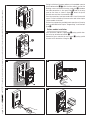 7
7
-
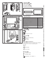 8
8
-
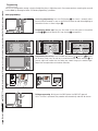 9
9
-
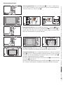 10
10
-
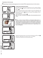 11
11
-
 12
12
-
 13
13
-
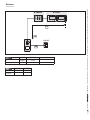 14
14
-
 15
15
-
 16
16
-
 17
17
-
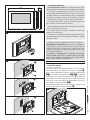 18
18
-
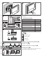 19
19
-
 20
20
-
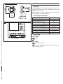 21
21
-
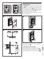 22
22
-
 23
23
-
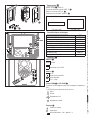 24
24
-
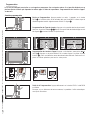 25
25
-
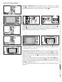 26
26
-
 27
27
-
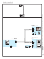 28
28
-
 29
29
-
 30
30
-
 31
31
-
 32
32
-
 33
33
-
 34
34
-
 35
35
-
 36
36
-
 37
37
-
 38
38
-
 39
39
-
 40
40
-
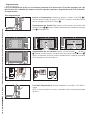 41
41
-
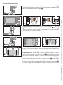 42
42
-
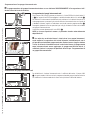 43
43
-
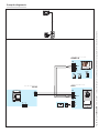 44
44
-
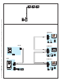 45
45
-
 46
46
-
 47
47
-
 48
48
-
 49
49
-
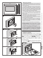 50
50
-
 51
51
-
 52
52
-
 53
53
-
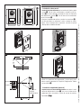 54
54
-
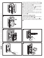 55
55
-
 56
56
-
 57
57
-
 58
58
-
 59
59
-
 60
60
-
 61
61
-
 62
62
-
 63
63
-
 64
64
-
 65
65
-
 66
66
-
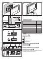 67
67
-
 68
68
-
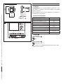 69
69
-
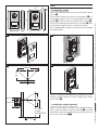 70
70
-
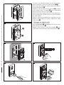 71
71
-
 72
72
-
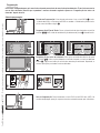 73
73
-
 74
74
-
 75
75
-
 76
76
-
 77
77
-
 78
78
-
 79
79
-
 80
80
-
 81
81
-
 82
82
-
 83
83
-
 84
84
-
 85
85
-
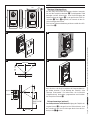 86
86
-
 87
87
-
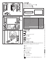 88
88
-
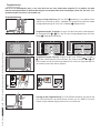 89
89
-
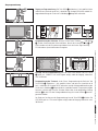 90
90
-
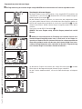 91
91
-
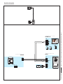 92
92
-
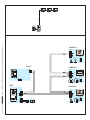 93
93
-
 94
94
-
 95
95
-
 96
96
-
 97
97
-
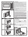 98
98
-
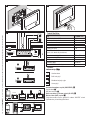 99
99
-
 100
100
-
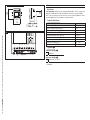 101
101
-
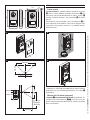 102
102
-
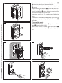 103
103
-
 104
104
-
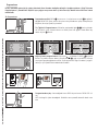 105
105
-
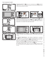 106
106
-
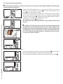 107
107
-
 108
108
-
 109
109
-
 110
110
-
 111
111
-
 112
112


en otros idiomas
- italiano: CAME Futura Guida d'installazione
- português: CAME Futura Guia de instalação
- Türkçe: CAME Futura Yükleme Rehberi
Artículos relacionados
-
CAME PERLA, PLACO Guía de instalación
-
-
-
-
-
-
-
-
-


