Danby DR202WGLP El manual del propietario
- Tipo
- El manual del propietario

DANBY PRODUCTS LIMITED, ONTARIO, CANADA N1H 6Z9
DANBY PRODUCTS INC., FINDLAY, OHIO, USA 45840
OWNER’S MANUAL
MANUEL DU PROPRIÉTAIRE
www.Danby.com
2018.08.13
COMPACT GAS RANGE
Owner’s Manual.............................1 - 26
ESTUFAS DE GAS COMPACTAS
Manuel du propriétaire.................27 - 52
MODEL * MODÈLE
DR202WGLP
DR202BGLP

1
Welcome
Welcome to the Danby family. We are proud of our quality products and we believe in
dependable service. We suggest that you read this owner’s manual before plugging in your new
appliance as it contains important operation information, safety information, troubleshooting and
maintenance tips to ensure the reliability and longevity of your appliance.
Visit www.Danby.com to access self service tools, FAQs and much more. For additional assistance
call 1-800-263-2629.
Note the information below; you will need this information to obtain service under warranty.
You must provide the original purchase receipt to validate your warranty and receive service.
Model Number: _________________________________________________
Serial Number: _________________________________________________
Date of Purchase: _______________________________________________
Need Help?
Before you call for service, here are a few things you can do to help us serve you better.
Read this owner’s manual:
It contains instructions to help you use and maintain your appliance properly.
If you receive a damaged appliance:
Immediately contact the retailer or builder that sold you the appliance.
Save time and money:
Check the troubleshooting section at the end of this manual before calling. This section
will help you solve common problems that may occur.
1-800-26- Danby
(1-800-263-2629)

2
Important Safety Information
READ AND FOLLOW ALL SAFETY INSTRUCTIONS
SAVE THESE INSTRUCTIONS!
ANTI-TIP BRACKET
To reduce the risk of the appliance tipping over, an
anti-tip bracket is provided that must be installed
before operating the appliance. See installation
instructions shipped with the bracket for complete
details.
1. Anti-tip bracket
2. Right side panel
3. Rear wall
4. Anti-tip bracket
5. Anti-tip arm
3
1
4
2
5
WARNING - TIP OVER HAZARD
• A child or adult can tip the appliance and be
killed.
• Verify the anti-tip bracket has been properly
installed and engaged to the fl oor or wall.
• Ensure the anti-tip bracket is re-engaged when
the range is moved by sliding the anti-tip arm
under the bracket.
• Do not operate the range without the anti-tip
bracket in place and engaged.
• Failure to follow these instructions can result in
death or serious burns to children or adults.
To check if the bracket is installed and engaged
properly, look underneath the range to see that
the anti-tip arm attached to the right side panel
is engaged on the bracket. On some models, the
storage drawer or kick panel can be removed for
easier inspection.
If visual inspection is not possible, slide the range
forward, confi rm the anti-tip bracket is securely
attached to the fl oor or wall and slide the range
back so the anti-tip arm slides under the anti-tip
bracket. If the range is pulled from the wall for
any reason, always repeat this procedure to verify
that the range is properly secured by the anti-tip
bracket.
WARNING - If the information in this
manual is not followed exactly, a fi re or
explosion may result, causing property
damage, personal injury or death.
• Do not store or use gasoline or other
fl ammable vapors and liquids in the
vicinity of this or any other appliance.
• Installation and service must be
performed by a qualifi ed installer,
service agency or the gas supplier.
WHAT TO DO IF YOU SMELL GAS
• Do not try to light any appliance.
• Do not touch any electrical switch.
• Do not use any phone in the building.
• Immediately call your gas supplier from
a neighbor’s phone. Follow the gas
supplier’s instructions.
• If you cannot reach your gas supplier,
call the fi re department.
WARNING - CARBON MONOXIDE
It is highly recommended to install a carbon
monoxide detector in your home.
Check local and national regulations concerning
installing and maintaining carbon monoxide
detectors.
IN THE COMMONWEALTH OF
MASSACHUSETTS
• This product must be installed by a licensed
plumber or gas fi tter.
• When using ball-type gas shut-off valves, they
shall be the T-handle type.
• A fl exible gas connector, when used, must not
exceed 3 feet in length.

3
Important Safety Information
READ AND FOLLOW ALL SAFETY INSTRUCTIONS
SAVE THESE INSTRUCTIONS!
GENERAL SAFETY REQUIREMENTS
Use this appliance for its intended purpose as
described in this Owner’s Manual.
Have your range installed and properly grounded
by a qualifi ed installer in accordance with the
provided installation instructions. Any adjustment
and service should be performed only by a qualifi ed
gas range installer or service technicians. Do not
attempt to repair or replace any part of your range
unless it is specifi cally recommended in this guide.
Your range is shipped from the factory set for use
with natural gas. It can be converted for use with LP
gas. If required, these adjustments must be made
by a qualifi ed technician in accordance with the
installation instructions and local codes. The agency
performing this work assumes responsibility for the
conversion.
Have the installer show you the location of the
range gas shut-off valve and how to turn it off if
necessary.
Plug your range into a 120-volt grounded outlet
only. Do not remove the round grounding prong
from the plug. If in doubt about the grounding of the
home electrical system, it is your responsibility and
obligation to have an ungrounded outlet replaced
with a properly grounded, three prong outlet in
accordance with the National Electrical Code. Do
not use an extension cord with this appliance.
Before performing any service, unplug the range
or disconnect the power supply at the household
distribution panel by removing the fuse or switching
off the circuit breaker.
Be sure all packing materials are removed from the
range before operating to prevent ignition of these
materials.
WARNING
NEVER use this appliance as a space heater to
heat or warm the room. Doing so may result in
carbon monoxide poisoning and overheating of
the oven.
Avoid scratching or impacting glass doors, the
cooktop or control panel. Doing so may lead to
glass breakage. Do not cook on a product with
broken glass. Shock, fi re or cuts may occur.
Do not leave children alone or unattended in an
area where an appliance is in use. They should
never be allowed to climb, sit or stand on any part
of the appliance.
Do not store items of interest to children above a
range or on the backguard of a range - children
climbing on the range to reach items could be
seriously injured.
Do not allow anyone to climb, stand or hang on the
oven door, drawer or cooktop. They could damage
the range or tip it over causing severe injury or
death.
Never block the vents (air openings) of the range.
They provide the air inlets and outlets that are
necessary for the range to operate properly with
correct combustion. Air openings are located at the
rear of the cooktop, at the top and bottom of the
oven door, and at the bottom of the range under the
warming drawer, lower oven drawer or kick panel.
Use only dry pot holders—moist or damp pot
holders on hot surfaces may result in burns from
steam. Do not let pot holders touch surface burners,
burner grates, or oven heating elements. Do not use
a towel or other bulky cloth in place of pot holders.
Be careful not to touch hot surfaces of the range.
Potentially hot surfaces include burners, grates,
cooktop, backguard, oven and door interior and
crevices around the oven door.
Do not heat unopened food containers. Pressure
could build up and the container could burst,
causing an injury.
Cook meat and poultry thoroughly - meat to at least
an internal temperature of 160°F and poultry to
at least an internal temperature of 180°F. Cooking
to these temperatures usually protects against
foodborne illness.

4
Important Safety Information
READ AND FOLLOW ALL SAFETY INSTRUCTIONS
SAVE THESE INSTRUCTIONS!
COOKTOP SAFETY INSTRUCTIONS
Never leave the range unattended while a surface
burner is ON. Foods, especially oily foods,
may ignite resulting in fi re that could spread to
surrounding cabinets.
Never leave oil unattended while frying. If allowed
to heat beyond its smoking point, oil may ignite
resulting in fi re that may spread to surrounding
cabinets. Use a deep fat thermometer whenever
possible to monitor oil temperature.
To avoid oil spillover and fi re, use a minimum
amount of oil when shallow pan-frying and avoid
cooking frozen foods with excessive amounts of ice.
Use proper pan size and avoid pans that are
unstable or easily tipped. Select cookware that is
matched to the size of the burner. Burner fl ames
should be adjusted so that they do not extend
beyond the bottom of the pan. Excessive fl ames may
be hazardous.
Always use the LITE position when igniting the top
burners and make sure the burners have ignited.
When using glass or ceramic cookware, make sure
it is suitable for cooktop service; others may break
because of sudden changes in temperature.
To minimize the possibility of burns, ignition of
fl ammable materials and spillage, the handle of a
container should be turned toward the center of the
range without extending over nearby burners.
When preparing fl aming foods under a hood, turn
the fan on.
Do not use a wok with a round metal support ring.
The ring may trap heat and block air to the burner
resulting in a carbon monoxide hazard.
Do not attempt to lift the cooktop if your range has
sealed surface burners. Doing so may damage the
gas tubing to the surface burners resulting in a gas
leak and risk of fi re.
Do not use aluminum foil to cover the grates or
line any part of the cooktop. Doing so may result
in carbon monoxide poisoning, overheating of the
cooktop surfaces, or a potential fi re hazard.
WARNING - FLAMMABLE MATERIALS
Do not store or use fl ammable materials in an oven
or near the cooktop, including paper, plastic, pot
holders, linens, wall coverings, curtains, drapes and
gasoline or other fl ammable vapors and liquids.
Never wear loose-fi tting or hanging garments while
using the appliance. Avoid storing commonly used
items in cabinets above the range and be careful
when reaching over the range. Clothing in close
proximity to burners or hot surfaces may ignite
causing severe burns.
Do not let cooking grease or other fl ammable
materials accumulate in or near the range. Grease
in the oven or on the cooktop may ignite.
Clean ventilating hoods frequently. Grease should
not be allowed to accumulate on the hood or fi lter.
WARNING - IN CASE OF FIRE
In the event of a fi re, never pick up a fl aming pot
or pan. Turn the burner off if it is safe to do so.
Extinguish the fi re with a dry chemical or foam-type
extinguisher.
Do not use water on grease fi res. Water will spread
the grease and will not extinguish the fi re. Smother
the fi re with a tight fi tting pot lid, cookie sheet or fl at
tray or use dry chemical or foam-type extinguisher.
If there is a fi re in the oven during baking, smother
the fi re by closing the oven door and turning
the oven off or use dry chemical or foam-type
extinguisher.

Important Safety Information
READ AND FOLLOW ALL SAFETY INSTRUCTIONS
5
SAVE THESE INSTRUCTIONS!
WARNING
NEVER cover any slots, holes or passages in
the oven bottom or cover and entire rack with
materials such as aluminum foil. Doing so blocks
air fl ow through the oven and may cause carbon
monoxide poisoning. Aluminum foil linings may
also trap heat, causing a fi re hazard.
OVEN SAFETY INSTRUCTIONS
Stand away from the range when opening the oven
door. Hot air or steam which escapes can cause
burns to hands, face and/or eyes.
Keep the oven free from grease build-up. Grease in
the oven may ignite.
Place oven racks in desired location while oven is
cool. If rack must be moved while oven is hot, do
not let potholder contact the hot heating element in
the oven.
Place oven racks in desired location while oven is
cool. If rack must be moved while oven is hot, be
careful to avoid touching hot surfaces.
Pull the oven rack to the stop-lock position when
loading and unloading food from the oven. This
helps prevent burns from touching hot surfaces of
the door and oven walls.
Do not leave items such as paper, cooking utensils
or food in the oven when not in use. Items stored in
an oven can ignite.
Do not leave items on the cooktop near the oven
vent which is in the center of the backguard. Items
may overheat resulting in a risk of fi re or burns.
When using cooking or roasting bags in the oven,
follow the manufacturer’s directions.
Never broil with door open. Open-door broiling is
not permitted due to overheating of control knobs.
LOWER OVEN DRAWER SAFETY
INSTRUCTIONS
The purpose of the warming drawer is to hold hot
cooked foods at serving temperature. Bacteria will
grow very rapidly in food that is between 40 and
140°F. Do not put cold food in the warming drawer.
Do not keep food in the warming drawer for more
than 2 hours. Failure to follow these instructions
may result in foodborne illness.
Do not leave paper products, plastics, canned food
or combustible materials in the drawer. They may
ignite.
Do not touch the heating element or the interior
surface of the drawer. These surfaces may be hot
enough to cause burns.
Use care when opening the drawer. Open the
drawer a crack and let hot air or steam escape
before removing or replacing food. Hot air or steam
that escapes can cause burns to hands, face and/
or eyes.
Do not use aluminum foil to line the warming
drawer. Foil is an excellent heat insulator and will
trap heat beneath it. This will upset the performance
of the drawer and potentially cause a fi re hazard.
WARNING
Read all safety instructions before using the
product. Failure to follow these instructions may
result in fi re, electric shock, serious injury or
death.

INSTALLATION INSTRUCTIONS
6
REQUIRED TOOLS
1. Phillips screwdriver
2. Flat blade screwdriver
3. Pencil and ruler
4. Pipe wrench
5. Open end or adjustable wrench
6. Level
7. Drill, awl or nail
FOR YOU SAFETY
Do not store or use combustible materials, gasoline
or other fl ammable vapors and liquids in the vicinity
of this or any other appliance.
If you smell gas:
1. Open windows.
2. Do not touch electrical switches.
3. Extinguish any open fl ame.
4. Immediately call your gas supplier.
1
2
3
4
5
6
7
MATERIALS YOU WILL NEED
1. Gas-line shut-off valve.
2. Pipe joint sealant or UL-approved pipe thread
tape with Tefl on* that resists action of natural
and LP gases.
3. Flexible metal appliance connector (1/2” I.D.)
A 5 foot length is recommended for ease of
installation but other lengths are acceptable.
Never use an old connector when installing a
new range.
4. Flare union adapter for connection to gas supply
line (3/4” or 1/2” NPT x 1/2” I.D.)
5. Liquid leak detector or soapy water.
6. Lag bolt or 1/2” O.D. sleeve anchor (for
concrete fl oors only).
*Tefl on is a registered trademark of DuPont.

INSTALLATION INSTRUCTIONS
7
INSTALLATION SAFETY INSTRUCTIONS
Read these instructions completely and carefully.
Failure to follow these instructions can result in
electrical shock, fi re, serious injury, or death.
Improper installation, adjustment, alteration, service
or maintenance can cause injury or property
damage. Refer to this manual. For assistance or
additional information, consult a qualifi ed installer,
service agency, manufacturer (dealer) or the gas
supplier.
Never reuse old fl exible connectors. The use of
old fl exible connectors can cause gas leaks and
personal injury. Always use new fl exible connectors
when installing a gas appliance.
Leak testing of the appliance shall be conducted
according to the manufacturer instructions.
Remove all packing material and literature from
oven before connecting gas and electrical supply to
range.
Do not attempt to operate the oven of this range
during a power failure.
Have your range installed by a qualifi ed installer.
Your range must be electrically grounded in
accordance with local codes or, in the absence
of local codes, in accordance with the National
Electrical Code, ANSI/NFPA 70, latest edition.
Your range must conform with local gas codes or, in
the absence of local codes, in accordance with the
National Fuel Gas Code, ANSI Z223.1/NFPA 54.
Appliances designed for manufactured mobile home
installtion must conform with the Manufactured
Home Construction and Safety Standard, Title 24
CFR, Part 3280, [formerly the Federal Standard
for Mobile Home Construction and Safety, Title
24, HUD (part 280)] or with local codes where
applicable.
Appliances designed for Recreational Park Trailers
must conform with the state or other codes or, in
the absence of such codes, with the Standard for
Recreational Park Trailers, ANSI A1 19.5.
Before installing your range on linoleum or any
other synthetic fl oor covering, make sure the fl oor
covering can withstand 180° F without shrinking,
warping or discoloring. Do not install the range
over carpeting unless a sheet of 1/4” thick plywood
or similar insulator is placed between the range and
carpeting.
Make sure the cabinets, fl oor, and wall coverings
around the range can withstand heat generated by
the range up to 200° F.
Avoid placing cabinets above the range. To reduce
the hazard caused by reaching over the open
fl ames of operating burners, install a ventilation
hood over the range that projects forward at least
5” beyond the front of the cabinets.
The ventilating hood must be constructed of sheet
metal not less than 0.0122” thick. Install above
the cooktop with a clearance of not less than
1/4” between the hood and the underside of the
combustible material or metal cabinet. The hood
must be at least as wide as the appliance and
centered over the appliance. Clearance between the
cooking surface and the ventilation hood surface
must never be less than 24”. Exception: Installation
of a listed microwave oven or cooking appliance
over the cooktop shall conform to the installation
instructions packed with that appliance.
If cabinets are placed above the range, allow a
minimum clearance of 30 “ between the cooking
surface and the bottom of unprotected cabinets.
If a 30” clearance between cooking surface and
overhead combustible material or metal cabinets
cannot be maintained, protect the underside of
the cabinets above the cooktop with not less than
1/4” insulating miliboard covered with sheet metal
not less than 0.0122” thick. Clearance between
the cooking surface and protected cabinets MUST
NEVER BE LESS THAN 24”.
The vertical distance from the plane of the cooking
surface to the bottom of adjacent overhead cabinets
extending closer than 1” to the plane of the range
sides must not be less than 18”. (See the Dimensions
and Clearances Illustration in this section).

INSTALLATION INSTRUCTIONS
8
DIMENSIONS AND CLEARANCES
Provide adequate clearances between the
range and adjacent combustible surfaces. These
dimensions must be met for safe use of the range.
The placement of the power outlet and the opening
of the piping can be adjusted to comply with the
specifi c requirements.
The range may be placed with 0” clearance below
the cooktop and at the back wall.
Minimum
E
36”
¾ ± ¼”
LOCATION
Do not locate the range where it may be subject
to strong drafts. Any openings in the fl oor or wall
behind the range should be sealed. Make sure the
openings around the base of the range that supply
fresh air for combustion and ventilation are not
obstructed by carpeting or woodwork.
Your range, like many other household items,
is heavy and can settle into soft fl oor coverings
such as cushioned vinyl or carpeting. Use care
when moving the range on this type of fl ooring.
It is recommended that the following simple and
inexpensive instructions be followed to protect your
fl oor.
The range should be installed on a sheet of plywood
or similar material. When the fl oor covering ends at
the front of the range, the area that the range will
rest on should be built up with plywood to the same
level or higher than the fl oor covering.
This will allow the range to be moved for cleaning
or servicing. Also,make sure your fl oor covering will
withstand 180° F.
Make sure the cabinets and wall coverings around
your range can withstand the heat generated (up to
200° F) by the range.
IMPORTANT
Remove all tape and packaging.
Make sure the burners are properly seated and
level.
Take the accessory pack out of the oven or drawer.
Check to be sure that no range parts have come
loose during shipping.
A: 19 3/4”
B: 19 3/4”
C: 2”
D: 44 3/8”
E: 41 3/4”

INSTALLATION INSTRUCTIONS
9
Remove the wire cover on the lower back of the
range by removing its top center screw. Do not
discard this screw.
Remove the knockout ring located on the bracket
directly below the terminal block. To remove the
knockout, use a pair of pliers to bend the knockout
ring away from the bracket and twist until the ring is
removed.
1. Terminal block
2. Knockout ring in bracket
3. Knockout ring removed
1
2
3
POWER CORD AND STRAIN RELIEF INSTALLATION
For power cord installations
Assemble the strain relief in the hole of the bracket.
If tabs are present at the end of the winged strain
relief they can be removed for a better fi t.
Insert the power cord through the strain relief and
tighten. Allow enough slack to easily attach the cord
terminals to the terminal block.
Do not install the power cord without a strain relief.
The strain relief bracket should be installed before
reinstalling the rear range wiring cover.
1. Terminal block
2. Strain relief
3. Bracket
4. Power cord
2
1
3
4
For conduit installations
Purchase a squeeze connector matching the
diameter of your conduit and assemble it in the
hole of the bracket. Insert the conduit through the
squeeze connector and tighten. Allow enough slack
to easily attach the wires to the terminal block.
Do not install the conduit without a squeeze
connector. The squeeze connector should be
installed before reinstalling the rear range wiring
cover.
1. Terminal block
2. Squeeze connector
3. Bracket
4. Conduit
1
2
3
4

INSTALLATION INSTRUCTIONS
10
1
2
3
4
5
3 WIRE POWER CORD INSTALLATION
The neutral or ground wire of the power cord must
be connected to the neutral terminal located in the
center of the terminal block. The power leads must
be connected to the lower left and the lower right
terminals of the terminal block.
1. Remove the three lower terminal screws from the
terminal block.
2. Insert the three terminal screws through each
power cord terminal ring and into the lower
terminals of the terminal block.
3. Be certain that the center wire is connected to
the center lower position of the terminal block.
4. Tighten screws securely into the terminal block.
5. Do not remove the ground strap connection.
1. Terminal block
2. Neutral terminal
3. Ground strap
4. Power cord
5. Ground plate

INSTALLATION INSTRUCTIONS
11
4 WIRE POWER CORD INSTALLATION
The neutral wire of the supply circuit must be
connected to the neutral terminal located in the
lower center of the terminal block. The power
leads must be connected to the lower left and the
lower right terminals of the terminal block. The 4th
grounding lead must be connected to the frame of
the range with the ground plate and the ground
screw.
1. Remove the three lower terminal screws from the
terminal block.
2. Remove the ground screw and ground plate and
retain them.
3. Cut and discard the ground strap. Do not
discard any screws.
4. Insert the one ground screw into the power cord
ground wire terminal ring, through the ground
plate and into the frame of the range.
5. Insert the three terminal screws that were
removed earlier through each power cord
terminal right and into the lower terminals of the
terminal block.
6. Be certain that the center wire is connected to
the center lower position of the terminal block.
7. Tighten the screws securely into the terminal
block.
After
1. Terminal block
2. Neutral terminal
3. Ground plate (grounding to range)
4. Ground screw
or
1
2
3
4
1
2
3
4
Before
1. Terminal block
2. Ground strap
3. Neutral terminal
4. Cut and discard the ground strap

INSTALLATION INSTRUCTIONS
12
To reduce the risk of the appliance tipping, the anti-
tip bracket must be installed before operation.
Note: The installation of the anti-tip bracket must
meet all local codes for securing the appliance.
The anti-tip bracket must be secured to either the
rear wall or the fl oor and must be positioned in such
a way that it will overhang the anti-tip arm on the
rear of the appliance.
Rear wall installation
Use the two screws provided to secure the bracket
to the rear wall. The screws must enter a wood sill
plate. If the wall contains any metal studs or similar
materials, or if the back of the appliance cannot
reach the rear wall, the fl oor installation should be
used.
Floor installation
Wood fl oor: Use the two screws provided to secure
the bracket to the fl oor.
Concrete fl oor:
1. Mark the location where the screws need to be
installed.
2. Use a power drill and a concrete bit to drill a
5/32” pilot hole 2” deep into the concrete at the
center of each of the marked locations.
3. Use the two screws provided to secure the
bracket to the fl oor.
Double check the installation
After installing the bracket, slide the appliance into
its fi nal location. Look underneath the appliance
and ensure that the anti-tip arm attached to the side
panel of the appliance is engaging the bracket.
ANTI-TIP BRACKET INSTALLATION
1. Anti-tip arm on the back of the appliance
2. Anti-tip bracket
3. Screw must enter wood or concrete
4. Wall sill plate
5. Screw must enter wood
1
2
3
4
5
ELECTRICAL CONNECTIONS
Electrical requirements:
120 volt, 60 hertz, properly grounded dedicated
circuit protected by a 15 amp or 20 amp circuit
breaker or time delay fuse.
NOTE: Use of automatic, wireless, or wired external
switches that shut off power to the appliance are not
recommended for this product.
WARNING SHOCK HAZARD: This appliance must
be properly grounded. Failure to do so can result in
electric shock.
The power cord of this appliance is equipped with
a three prong (grounding) plug which mates with
a standard three-prong grounding wall receptacle
to minimize the possibility of electric shock hazard
from this appliance.
The customer should have the wall receptacle and
circuit checked by a qualifi ed electrician to make
sure the receptacle is properly grounded.
Where a standard two-prong wall receptacle is
encountered, it is the personal responsibility and
obligation of the customer to have it replaced with a
properly grounded three-prong wall receptacle.
DO NOT, UNDER ANY CIRCUMSTANCES, CUT OR
REMOVE THE THIRD (GROUND) PRONG FROM
THE POWER CORD.
DO NOT USE AN ADAPTER.
DO NOT USE AN EXTENSION CORD.
A word about GFCIs - GFCIs are not required or
recommended for gas range receptacles.
Ground Fault Circuit Interrupters (GFCIs) are
devices that sense leakage of current in a circuit and
automatically switch off power when a threshold
leakage level is detected. These devices must be
manually reset by the consumer. The National
Electrical Code requires the use of GFCIs in kitchen
receptacles installed to serve countertop surfaces.
Performance of the range will not be affected if
operated on a GFCI-protected circuit but occasional
nuisance tripping of the GFCI breaker is possible.

INSTALLATION INSTRUCTIONS
13
INSTALL THE RANGE
1. Provide adequate gas supply
Your range is designed to operate at a pressure of
5” of water column on natural gas or, if desired for
LP gas (propane or butane), 10” of water column.
Make sure you are supplying your range with the
type of gas for which it is designed.
This range is convertible for use on natural or
propane gas. If you decide to use this range on LP
gas, conversion must be made by a qualifi ed LP
installer before attempting to operate the range on
that gas.
For proper operation, the pressure of natural gas
supplied to the regulator must be between 6” and
13” of water column.
For LP gas, the pressure supplied must be between
11” and 13” of water column.
When checking for proper operation of the
regulator, the inlet pressure must be at least 1”
greater than the operating (manifold) pressure as
given above.
The pressure regulator located at the inlet of the
range must remain in the supply line regardless of
whether natural or LP gas is being used.
A fl exible metal appliance connector used to
connect the range to the gas supply line should have
an I.D. of 1/2” and be 5 feet in length for ease of
installation. In Canada, fl exible connectors must be
single wall metal connectors no longer than 6 feet in
length.
INSTALL THE RANGE
2. Connect the range to gas
Shut off the main gas supply valve before
disconnecting the old range and leave it off until the
new hook-up has been completed. Don’t forget to
relight the pilot on other gas appliances when you
turn the gas back on.
Because hard piping restricts movement of the
range, the use of a CSA International-certifi ed
fl exible metal appliance connector is recommended
unless local codes require a hard-piped connection.
Never use an old connector when installing a new
range. If the hard piping method is used, you must
carefully align the pipe, the range cannot be moved
after the connection is made.
To prevent gas leaks, put pipe joint compound on,
or wrap pipe thread tape with Tefl on around all
male (external) pipe threads.
Installation steps:
1. Install a manual gas line shut-off valve in the gas
line in an easily accessed location outside of the
range. Make sure everyone operating the range
knows where and how to shut off the gas supply
to the range.
2. Install male 1/2” fl are union adapter to the
1/2” NPT internal thread at inlet of regulator.
Use a backup wrench on the regulator fi tting
to avoid damage. When installing the range
from the front, remove the 90° elbow for easier
installation.
3. Install male 1/2” or 3/4” fl are union adapter
to the NPT internal thread of the manual shut-off
valve to keep it from turning.
4. Connect fl exible metal appliance connector to
the adapter on the range. Position range to
permit connection at the shut-off valve.
5. When all connections have been made, make
sure all range controls are in the off position and
turn on the main gas supply valve. Use a liquid
leak detector at all joints and connections to
check for leaks in the system.

1
2
14
INSTALLATION INSTRUCTIONS
WARNING
Fire hazard: Do not use a fl ame to check for gas leaks.
Recommended gas and electric supply location
When using test pressures greater than 1/2 psig to pressure test the gas supply system of the residence,
disconnect the range and individual shut-off valve from the gas supply piping. When using test pressures
of 1/2 psig or less to test the gas supply system, simply isolate the range from the gas supply system by
closing the individual shut-off valve.
Note: Recommended gas hook-up locations behind the range. Gas and shut-off valve should not protrude
more than 2” from the wall to allow the range to rest against the wall.
Check local codes before making connections.
1. Electrical connection area
2. Gas hook-up area
A. 20 3/8”
B. (minimum distance to
walls above the cooktop
on each side): 2”
C. 2”
D. 2 1/2”

15
INSTALLATION INSTRUCTIONS
FLEXIBLE CONNECTOR HOOKUP EXAMPLE
To the installer: Inform the consumer of the location
of the gas shut-off valve and leave these instructions
with the consumer for future use.
Note: The arrow indicates the direction of gas fl ow
into the range.
1. Pressure regulator
2. Adapter
3. Flex connector (4 1/2 feet maximum)
4. Adapter
5. Gas shut off valve
6. 1/2” or 3/4” gas pipe
1
2
3
4
5
6
RIGID CONNECTOR HOOKUP EXAMPLE
To the installer: Inform the consumer of the location
of the gas shut-off valve and leave these instructions
with the consumer for future use.
Note: The arrow indicates the direction of gas fl ow
into the range.
1. Pressure regulator
2. Black iron pipe 4 1/2”
3. 90° elbow
4. Nipple (may not be required)
5. 90° elbow
6. Black iron pipe
7. Union
8. Nipple
9. Gas shut off valve
10. 1/2” or 3/4” gas pipe
1
2
4
5
6
7
8
9
10
3
INSTALL THE RANGE
3. Seal the openings
Seal any openings in the wall behind the range
and in the fl oor under the range when hookups are
completed.

INSTALLATION INSTRUCTIONS
16
INSTALL THE RANGE
4. Electric ignition
There are separate ignition devices for the left and
right hand surface burners. Both of these ignition
devices are ON when any knob is turned to the LITE
setting. The ignition devices will spark as long as
any of the top burner knobs are at the LITE setting.
In the event of an electrical power failure, the top
knobs can still be used. To light a burner, hold a lit
kitchen match adjacent to the top burner to be used
and turn the valve knob to LITE.
USE EXTREME CAUTION WHEN LIGHTING A
BURNER THIS WAY.
5. Adjust the oven burner air shutter
For Natural Gas: The oven burner fl ame should
be a clean, blue fl ame with distinct inner cones
approximately 1/2” long. A soft, lazy fl ame with
indistinct cones means too much gas or not enough
air. A noisy lifting fl ame means too much air.
INSTALL THE RANGE
If burner adjustment is necessary:
Loosen the lock screw located at the top of the air
shutter, then rotate the air shutter to the correct
position and retighten the screw.
1. Air shutter
2. Lock screw
For LP gas: The fl ame should have approximately
1-inch blue cones. After 30 seconds of burner
operation, check for fl ames lifting off the burner
ports. If lifting is observed, gradually reduce the air
shutter opening until fl ames are stabilized. Some
yellow tipping may be normal for LP gas.
1
2
The oven burner fl ame can be checked as follows
(without burner baffl e in place):
• To correct a yellow fl ame, increase size of air
shutter opening.
• To correct a lifting, but distinct, blue fl ame,
decrease size of air shutter opening.
The air shutter should be set approximately 2/3
open for natural gas, and approximately full open
for LP gas.

INSTALLATION INSTRUCTIONS
17
INSTALL THE RANGE
6. Quality of fl ames
The combustion quality of burner fl ames needs to be
determined visually.
A: Yellow fl ames; call for service
B: Yellow tips on outer cones; normal for LP gas
C: Soft blue fl ames; normal for natural gas
A
B
C
7. Replace the oven parts
Once all adjustments are completed, ensure all
oven parts are installed correctly such as the bottom
drawer, the oven shelves and the oven door.
INSTALL THE RANGE
8. Level the range
Check that the appliance is level using a spirit level
or a clear measuring cup partially fi lled with water.
Ensuring that the oven is level will ensure even
cooking.
Use an open end or adjustable wrench to adjust
the leveling legs. Turn the leg clockwise to raise the
range. Turn the leveling leg counterclockwise to
lower the range.
INSTALLATION CHECK LIST
• Make sure all controls are in the OFF position.
• Make sure the fl ow of combustion and
ventilation air to the range is unobstructed.
• Make sure all oven parts are installed correctly.
• Double check that the anti-tip bracket is installed
and working correctly.
CONVERT TO LP GAS
This range leaves the factory set for use with natural
gas. The conversion to LP gas must be performed by
a qualifi ed LP gas installer.
The conversion instructions and LP orifi ces can be
found attached to the back of the range.

18
OPERATING INSTRUCTIONS
USING GAS SURFACE BURNERS
Before lighting a gas burner:
• Make sure all burners are in place.
• Make sure all grates on the range are properly
places before using any burner.
After lighting a gas burner:
• Do not operate the burner for an extended
period of time without cookware on the grate.
The fi nish on the grate may discolor or chip
without cookware to absorb the heat.
• Be sure the burners and grates are cool before
you place your hand, a pot holder, cleaning
cloths or other materials on them.
How to light a gas surface burner:
• Make sure all the surface burners are placed in
their respective positions.
• Push the control knob in and turn it to the LITE
position.
• You will hear a clicking noise, this is the sound
of the electric spark igniting the burner.
• Turn the knob to adjust the fl ame size. If the
knob stays at LITE, it will continue to click.
• When one burner is turned to LITE, all the
burners spark. Do not attempt to disassemble or
clean around any burner while another burner
is on. An electric shock may result, which could
cause you to knock over hot cookware.
• Watch the fl ame, not the knob, as you adjust
heat. When fast heating is desired, the fl ame
size on a gas burner should match the cookware
you are using.
• Flames larger than the bottom of the cookware
will not result in faster heating and may be
hazardous.
ACCEPTABLE COOKWARE
Aluminum: Medium-weight cookware is
recommended because it heats quickly and evenly.
Most foods brown evenly in an aluminum skillet.
Use saucepans with tight-fi tting lids when cooking
with minimum amounts of water.
Cast-Iron: If heated slowly, most skillets will give
satisfactory results.
Enamelware: Under some conditions, the enamel
of some cookware may melt. Follow cookware
manufacturer’s recommendations for cooking
methods.
Glass: There are two types of glass cookware—
those for oven use only and those for top-of-range
cooking (saucepans, coffee and teapots). Glass
conducts heat very slowly.
Heatproof Glass Ceramic: Can be used for either
surface or oven cooking. It conducts heat very
slowly and cools very slowly. Check cookware
manufacturer’s directions to be sure it can be used
on gas ranges.
Stainless Steel: This metal alone has poor heating
properties and is usually combined with copper,
aluminum or other metals for improved heat
distribution. Combination metal skillets usually work
satisfactorily if they are used with medium heat as
the manufacturer recommends.
IN CASE OF POWER FAILURE
In case of a power failure, you can light the surface
burners on your range with a match. Hold a lit
match to the burner ports, then slowly turn the
control knob to the LITE position. Use extreme
caution when lighting burners this way.
Surface burners in use when an electrical power
failure occurs will continue to operate normally.
WARNING
Flames that are not covered by cookware
may present a risk of burns or clothing
ignition. Never let fl ames extend beyond the
sides of the cookware.

19
OPERATING INSTRUCTIONS
USING THE OVEN
Oven controls
The oven is controlled by the oven temp knob. It can
take up to 90 seconds before the fl ame comes on.
After the oven reaches the selected temperature, the
oven burner maintains the selected temperature.
IN CASE OF POWER FAILURE
The oven or broiler cannot be lit during a power
failure.
If the oven is in use when a power failure occurs,
the oven burner shuts off. This is because the fl ow
of gas is automatically stopped and will not resume
until power is restored.
UPPER OVEN VENT
Your oven is vented through ducts at the rear of the
range. Do not block these ducts when cooking in
the oven - it is important that the fl ow of hot air
from the oven and fresh air to the oven burner be
uninterrupted. Avoid touching the vent openings or
nearby surfaces during oven or broiler operations -
they may become hot.
Handles of pots and pans on the cooktop may
become hot if left too close to the vent.
Do not leave plastic or fl ammable items on the
cooktop - they may melt or ignite if left too close to
the vent.
Do not leave closed containers of the cooktop. The
pressure in closed containers may increase, which
may cause them to burst.
Metal items will become very hot if they are left on
the cooktop, and could cause burns.
OVEN SHELVES
The oven shelves are designed with stop-locks so
that when they are placed correctly on the shelf
supports, they will stop before coming completely
out of the oven and will not tilt when food is being
removed or added.
To remove the shelves from the oven, pull the shelf
outward, tilt the front end upward and pull it out.
To replace the shelves, place the shelf on the support
with the stop locks facing up and toward the back of
the oven. Tilt up the front and push the shelf toward
the back of the oven until it goes past the bump on
the shelf support, then lower the front of the shelf
and push it all the way into the oven.
The oven has four different shelf support positions to
accommodate different cooking requirements.
SHELF POSITIONS
• Most baking is done on the second or third shelf
position from the bottom of the oven.
• When baking multiple items, use two shelves
positioned on the second and fourth shelf
supports from the bottom of the oven.
• Roasting is usually done on the bottom shelf
position.
• As a general rule, place most foods in the
middle of the oven on the second or third shelf.
• Pans should not touch each other or the walls
of the oven. Allow 1 to 1 1/2 inches of space
between pans as well as from the back of the
oven, the door and the sides. If you need to
use two shelves stagger the pans so one is not
directly above the other.

OPERATING INSTRUCTIONS
OVEN BROILING
Broiling is cooking food by direct heat from above
the food. Most fi sh and tender cuts of meat can be
broiled. The range has a compartment below the
oven for broiling. A specially designed broiler pan
allows dripping fat to drain away from the food.
Both the oven door and broiler compartment drawer
should be closed during broiling.
1. Preheating the boiler drawer is not necessary
and can produce poor results.
2. If the meat has fat or gristle around the edge,
cut vertical slashes through both about 2” apart.
If desired, fat may be trimmed, leaving a layer
about 1/8” thick.
3. Place the meat on a broiler grid in a broiler pan
designed for broiling. Always use the grid so
the fat drips into the broiler pan; otherwise the
juices may become hot enough to catch fi re.
4. Place the food in the broiler and close the door.
5. Turn the oven temperature knob to BROIL.
6. Food can be turned during broiling if necessary.
Be cautious of hot air or steam when opening
the oven door.
7. Make sure to turn the oven temperature knob to
OFF once broiling is complete.
BROILING TIPS
• Always use the broiler pan and grid that comes
with your range. It is designed to minimize
smoking and spattering by trapping juices in the
shielded lower part of the pan.
• For steaks and chops, slash fat evenly around
the outside edges of the meat. Use tongs to turn
the meat over to prevent piercing the meat and
losing juices.
• If desired, marinate meats before broiling, or
brush with barbecue sauce in the last 5-10
minutes only.
• When arranging the food on the pan, do not
let fatty edges hang over the sides because
dripping fat could soil the oven.
• Frozen steaks can be broiled by positioning
the rack at the next lowest rack position and
increasing the cooking time 1 1/2 times per
side.
• Aluminum foil can be used to line the broiler
pan and grid, however, it must be molded tightly
to the grid and slits must be cut in the foil so that
fat and juices can leak through into the lower
part of the pan.
20
OVEN BAKING AND ROASTING
1. Position the shelves in the oven. If cooking on
two shelves at the same time, stagger the pans
for the best heat circulation.
2. Place the food on the center of the oven shelf.
Allow at least 2 inches between the end of the
pan and the oven wall or any adjacent pans.
3. Turn oven temperature knob to the desired
temperature.
4. Check the food regularly. Remove once done
and ensure the oven is turned off.
BAKING AND ROASTING TIPS
• Follow a tested recipe and measure the
ingredients carefully. If you are using a package
mix, follow label directions.
• Do not open the oven door while baking or
roasting. Heat will be lost and the cook time
might need to be extended. If you must open the
door, open it partially and close it as quickly as
possible.
• Roasting is cooking by dry heat. Tender meat
or poultry can be roasted uncovered. Roasting
temperatures, which should be low and steady,
keep spattering to a minimum. When roasting,
it is not necessary to sear, baste, cover, or add
water to the meat.
• Frozen roasts of meat can be cooked without
thawing, but allow 10 to 25 minutes of
additional time per pound of meat (10 minutes
per pound for roasts under 5 pounds, more time
for larger roasts).
• Thaw frozen poultry before roasting to ensure
even cooking. Some commercial frozen poultry
can be cooked successfully without thawing.
Follow directions given on package label.
SAFE COOKING
The USDA recommends the following minimum safe
internal temperatures:
• Raw beef, pork, lamb and veal steaks or chops:
145°F as measured with a food thermometer
before removing meat from the heat source. For
safety and quality, allow meat to rest for at least
three minutes before carving or consuming.
• Raw ground beef, pork, lamb or veal: 160°F as
measured with a food thermometer.
• Poultry: 165°F as measured with a food
thermometer.
• For more information, visit: www.isitdoneyet.gov
or call toll free to the USDA meat and poultry
hotline at 1-888-674-6854.

OPERATING INSTRUCTIONS
21
ADJUST THE OVEN THERMOSTAT
You may fi nd that the new oven cooks differently
than the one it replaced. Use the new oven for a
few weeks to become familiar with it. If you still fi nd
the oven is too hot or too cold, you can adjust the
thermostat.
Do not use thermometers, such as those found in
grocery stores to check the temperature of the oven.
They are not calibrated for high temperatures and
can vary from 20 - 40 degrees.
This adjustment will not affect the broiling
temperatures. The adjustment will be retained after
a power failure.
1. Pull the oven temperature knob off the
range and look at the back of it. To make an
adjustment, loosen by one turn the two screws
on the back of the knob. Do not completely
remove the screws.
2. With the back of the knob facing you, hold the
outer edge of the knob with one hand and turn
the front of the knob with the other hand.
3. To increase the oven temperature, move the top
screw toward the right.
4. To decrease the oven temperature, move the top
screw toward the left.
5. You will hear a click for each notch you move
the knob. Each click will change the oven
temperature approximately 10°F. The range is
plus or minus 60°F from the arrow. We suggest
that you adjust the temperature by one click and
then test the oven performance before adjusting
further.
6. After the adjustment is made, retighten the
screws so they are snug. Be careful not to over-
tighten.
7. Replace the knob, matching the fl at area of the
knob to the shaft.
L
O
O
S
E
N
R
E
S
C
W
T
S
R
O
O
T
E
A
T
K
E
O
M
A
C
E
O
L
R
K
M
A
E
T
H
O
T
E
R
ALUMINUM FOIL
Do not use aluminum foil to line the bottom of
the oven. The foil will trap heat below and upset
the performance of the oven. Foil can melt and
permanently damage the bottom of the oven.
Damage from improper use of aluminum foil is not
covered by the product warranty.
Foil may be used to catch spills by placing a sheet
on a lower rack, several inches below the food. Do
not use more foil than necessary and never entirely
cover an oven rack with aluminum foil. Keep foil at
least 1 to 1 1/2 inches from oven walls to prevent
poor heat circulation.
OVEN MOISTURE
As the oven heats up, the temperature change of the
air in the oven may cause water droplets to form on
the door glass. These droplets are harmless and will
evaporate as the oven continues to heat up.
OVEN AIR VENTS
Never block the air vents. They provide the air
inlet and outlet that are necessary for the range to
operate properly with correct combustion.
Air openings are located at the rear of the cooktop,
at the top and bottom of the oven door, and at the
bottom of the range.
Vent appearance and location may vary.

22
CARE & MAINTENANCE
BURNER GRATES
The range has two or three professional-style
double grates. These grates are position specifi c.
For maximum stability, these grates should only
be used in their proper position; they cannot be
interchanged left to right or front to back.
For convenience, the undersides of the left and
right grates are marked “LEFT FRONT” and “RIGHT
FRONT”. Make sure the front portion of both grates
is in front. The middle grate has a bow in front.
Make sure the bowed portion is toward the front of
the range. In addition, the middle grate is supported
by the left and right grates and must be installed last
for stability.
Cleaning burner grates
Lift out when cool. Grates should be washed
regularly and, of course, after spillovers. Wash
them in hot, soapy water and rinse with clean
water. When replacing the grates, be sure they are
positioned securely over the burners.
Replace the grates so that continuous arcs are
formed with the center ribs of all three grates.
Do not operate a burner for an extended period of
time without cookware on the grate. The fi nish on
the grate may chip without cookware to absorb the
heat.
To get rid of burned-on food, place the grates in a
covered container. Add 1/4 cup ammonia and let
soak several hours or overnight. Wash, rinse well
and dry.
Although they are durable, the grates will gradually
lose their shine, regardless of the best care you can
give them. This is due to their continual exposure to
high temperatures. You will notice this sooner with
lighter color grates.
CLEANING
Cooktop surface
To avoid damaging the porcelain-enamel surface of
the cooktop and to prevent it from becoming dull,
clean up spills right away. Foods with a lot of acid
or foods with high sugar content could cause a dull
spot if allowed to set.
When the surface has cooled, wash and rinse. For
other spills such as fat spattering, wash with soap
and water once the surface has cooled. Then rinse
and polish with a dry cloth.
Control panel and knobs
It is a good idea to wipe the control panel after
each use of the oven. Use a damp cloth to clean or
rinse. For cleaning, use mild soap and water or a
50/50 solution of vinegar and water. For rinsing,
use clean water. Polish dry with a soft cloth.
Do not use abrasive cleansers, strong liquid
cleaners, plastic scouring pads or oven cleaners on
the control panel as they will damage the fi nish.
Do not try to bend knobs by pulling them up or
down or by hanging a towel or other such loads.
This can damage the gas valve shaft.
The control knobs may be removed for easier
cleaning. Make sure the knobs are in the OFF
positions and pull them straight off the stems for
cleaning. The knobs can be cleaned in a dishwasher
or they may also be washed with soap and water.
Make sure the insides of the knobs are dry before
replacing.
Replace the knobs in the OFF position to ensure
proper placement. Note that knobs are not
interchangeable. Be sure to reinstall the knobs to the
original location.
Metal parts can be cleaned with soap and water.
Do not use steel wool, abrasives, ammonia, acids or
commercial oven cleaners. Dry with a soft cloth.

CARE & MAINTENANCE
23
Removable oven bottom
On some models the bottom panel of the oven is
removable and can be washed separately.
To remove the oven bottom:
1. Remove the knurled screw in the front of the
oven bottom.
2. Grasp each side of the oven bottom and push
back.
3. Lift the front up and pull it out of the oven.
To replace the oven bottom:
1. Grasp each side of the oven bottom and guide
its rear tabs into the slots in the back of the oven.
2. Lower the oven bottom and pull it forward until it
is secure under the front oven fl oor edge.
3. On models so equipped, replace the knurled
screw in the front of the oven bottom.
NOTE: If the oven bottom is replaced incorrectly, it
may warp and cause undesirable baking results.
Broiler compartment
The broiler pan is held in place in the broiler rack.
To remove the broiler pan:
1. Gently pull forward on the drop down broiler
door.
2. Pull the broiler rack with pan forward until the
rack stops.
3. Grasp the broiler pan and remove it from the
broiler rack.
To replace the broiler pan:
1. Slide the broiler pan onto the rack and push
both the broiler pan and the rack all the way
into the broiler compartment.
2. Close the broiler door.
If a spillover occurs in the broiler compartment,
allow the compartment to cool fi rst. You can clean
the compartment with soap and water, a mild
abrasive cleanser, soap-fi lled scouring pads or an
oven cleaner following package directions.
Oven shelves and broiler rack
The shelves and broiler rack can be cleaned by
hand using soap and water or with an abrasive
cleaner or steel wool. After cleaning, rinse the
shelves and broiler rack with clean water and dry
with a clean cloth.
After cleaning, grease all oven rack edges with a
light coating of vegetable oil. This will help maintain
the ease of sliding the racks in and out of the oven.
Porcelain oven interior
With proper care, the porcelain enamel interior will
retain its fi nish for many years.
Soap and water can be used to clean the interior.
Heavy splattering or spills may require cleaning
with a mild abrasive cleaner.
Do not allow spills with high acid content such as
milk, tomatoes, fruit juices or pie fi lling, to remain
on the surface. They may cause dull spots even after
cleaning.
Household ammonia may make cleaning easier.
Place 1/2 cup of ammonia in a shallow glass pan
and leave in a cold oven over night. The ammonia
fumes will help loosen burned on grease and food.
Cautions about using spray-on oven cleaners
Do not spray oven cleaner on the electrical controls
and switches as it could cause a short circuit and
result in sparking or fi re.
Do not allow a fi lm from the oven cleaner to remain
on the temperature sensor as it could cause the oven
to heat improperly. The sensor is located on the top
of the oven. Carefully wipe the bulb clean after each
oven cleaning, being careful not to move the sensor
since a change in its position could affect how the
oven bakes.
Do not spray oven cleaner on the outside of the
oven door, handles or any exterior surface of the
oven, cabinet or painted surfaces. The cleaner can
damage these surfaces.

CARE & MAINTENANCE
24
Broiler pan and guard
After broiling, remove the broiler pan from the
oven. Remove the grid from the pan. Carefully pour
out grease from the pan into a proper container.
Wash and rinse the broiler pan and grid in hot
water with a soap-fi lled or plastic scouring pad.
If food has burned on, sprinkle the grid with
detergent while hot and cover with wet paper towels
or a dishcloth. Soaking the pan will remove burned
on foods.
Do not store a soiled broiler pan and grid anywhere
in the range.
Removable oven door
The oven door is removable but it is heavy. It
is recommended that at least two people work
together to remove it.
To remove the door:
1. Open the door to the full open position.
2. Pull the hinge locks up over the hinge hooks on
both sides.
3. Grasp the door fi rmly on both sides, lift slightly
and pull it straight out and away from the oven.
To replace the door:
1. Firmly grasp both sides of the door at the top.
2. Insert and seat the upper and lower hinge arms
into the oven slots.
3. Push the hinge locks down from the hinge hooks.
4. Close the oven door and make sure it is working
properly. If it seems uneven or does not close
completely, remove it again and repeat the steps
to replace it.
Note: Do not attempt to close the door until it is
properly installed. The hinges could be damaged.
Glass door window
To clean the outside of the glass door window, use a
glass cleaner. Rinse and polish with a dry cloth.
Avoid scratching or impacting the glass window.
Doing so may cause the glass to break.
OVEN LIGHT REPLACEMENT
Important: Before replacing the oven light bulb,
make sure the electrical power is disconnected from
the appliance. Failure to do so may result in electric
shock or burn.
Be sure to let the light cover and bulb cool
completely before replacing.
Removing the oven door can make this process
easier.
To remove the light cover:
1. Twist the lens counterclockwise roughly 1/4 turn
to remove. Do not remove any screws to remove
the light cover.
2. Do not touch the light bulb with a wet cloth.
Replace the light bulb with a 40 watt appliance
light bulb.
To replace the light cover:
1. Line up the tabs of the lens with the tabs on the
light housing and rotate clockwise by roughly
1/4 turn to install.

PROBLEM POSSIBLE CAUSE
No power • A fuse may be blown or the circuit breaker tripped
• Plug not fully inserted into the wall outlet
Surface elements not working properly • Burner holes on the side or around the top of the burner
may be clogged.
• Burners may not be fi tted correctly onto the mounting
brackets.
Burners have yellow or yellow-tipped
fl ames
• The combustion quality of burner fl ames needs to be
determined visually. See the “Quality of fl ames” section of
the installation instructions for more information.
Burner fl ames very large or yellow • LP gas is improperly connected.
• The thermostat capillary bulb must be clean and
unobstructed.
• The oven vent is blocked.
• Oven control improperly set.
• Improper size of cookware is being used.
Strong odor • Improper air to gas ratio in the oven.
• An odor from the insulation around the oven liner is
normal the fi rst few times the oven is used.
Surface burners light but oven does not • The oven gas shut off valve may have been accidentally
moved during cleaning or moving. Raise the cook top
and look for the gas shut off lever in the left rear corner.
Ensure the lever is in the open position.
Oven light does not work • Light bulb is loose
• Light switch is not operating correctly
TROUBLESHOOTING
Danby Consumer Care: 1-800-263-2629
Hours of operation:
Monday to Thursday 8:30 am - 6:00 pm Eastern Standard Time
Friday 8:30 am - 4:00 pm Eastern Standard Time
Information in this manual is subject to change without notice.
25

LIMITED IN-HOME APPLIANCE WARRANTY
This quality product is warranted to be free from manufacturer’s defects in material and workmanship, provided that the unit is used under the normal operating
conditions intended by the manufacturer.
This warranty is available only to the person to whom the unit was originally sold by Danby Products Limited (Canada) or Danby Products Inc. (U.S.A.) (hereafter
“Danby”) or by an authorized distributor of Danby, and is non-transferable.
TERMS OF WARRANTY
Plastic parts, are warranted for thirty (30) days only from purchase date, with no extensions provided.
First Year
During the rst twelve (12) months, any functional parts of this product found to be defective, will be repaired or replaced, at warrantor’s
option, at no charge to the ORIGINAL purchaser.
To obtain
Danby reserves the right to limit the boundaries of “In Home Service” to the proximity of an Authorized Service Depot. Any app liance
Service
requiring service outside the limited boundaries of “In Home Service” , it will be the consumer’s responsibility to transport the appliance (at
their own expense) to the original retailer (point of purchase) or a service depot for repair. See “Boundaries of In Home Serv ice” below.
Contact your dealer from whom your unit was purchased, or contact your nearest authorized Danby service depot, where service
must be performed by a qualied service technician.
If service is performed on the units by anyone other than an authorized service depot, or the unit is used for commercial appli cation, all
obligations of Danby under this warranty shall be void.
Boundaries of
If the appliance is installed in a location that is 100 kilometers (62 miles) or more from the nearest service center your unit must be
In Home Service
delivered to the nearest authorized Danby Service Depot, as service must only be performed by a technician qualied and certif ied for
warranty service by Danby. Transportation charges to and from the service location are not protected by this warranty and are t he
responsibility of the purchaser.
Nothing within this warranty shall imply that Danby will be responsible or liable for any spoilage or damage to food or other c ontents of this appliance, whether due
to any defect of the appliance, or its use, whether proper or improper.
EXCLUSIONS
Save as herein provided, Danby, there are no other warranties, conditions, representations or guarantees, express or implied, m ade or intended by Danby or its
authorized distributors and all other warranties, conditions, representations or guarantees, including any warranties, conditio ns, representations or guarantees
under any Sale of Goods Act or like legislation or statue is hereby expressly excluded. Save as herein provided, Danby shall no t be responsible for any damages
to persons or property, including the unit itself, howsoever caused or any consequential damages arising from the malfunction o f the unit and by the purchase of
the unit, the purchaser does hereby agree to indemnify and hold harmless Danby from any claim for damages to persons or propert y caused by the unit.
GENERAL PROVISIONS
No warranty or insurance herein contained or set out shall apply when damage or repair is caused by any of the following:
1) Power failure.
2) Damage in transit or when moving the appliance.
3) Improper power supply such as low voltage, defective house wiring or inadequate fuses.
4) Accident, alteration, abuse or misuse of the appliance such as inadequate air circulation in the room or abnormal operating con ditions
(extremely high or low room temperature).
5) Use for commercial or industrial purposes (ie. If the appliance is not installed in a domestic residence).
6) Fire, water damage, theft, war, riot, hostility, acts of God such as hurricanes, oods etc.
7) Service calls resulting in customer education.
8) Improper Installation (ie. Building-in of a free standing appliance or using an appliance outdoors that is not approved for out door application).
Proof of purchase date will be required for warranty claims; so, please retain bills of sale. In the event warranty service is required, present this document to our
AUTHORIZED SERVICE DEPOT.
Danby Products Limited
PO Box 1778, Guelph, Ontario, Canada N1H 6Z9
Telephone: (519) 837-0920 FAX: (519) 837-0449
Danby Products Inc.
PO Box 669, Findlay, Ohio, U.S.A. 45840
Telephone: (419) 425-8627 FAX: (419) 425-8629
04/09
1-800-263-2629
Warranty Service
In-home
Danby reserves the right to limit the boundaries of “In Home Service” to the proximity of an authorized service
depot. Any appliance requiring service outside the limited boundaries of “In Home Service”, will be the consumer’s
responsibility to transport at their own expense to the original point of purchase or a service depot for repair. If the
appliance is installed in a location that is 100 kilometers (62 miles) or more from the nearest service center, it must
be delivered to the nearest authorized Danby Service Depot by the purchaser.
Transportation charges to and from the service location are not protected by this warranty and are the
responsibility of the purchaser.
During the first twelve (12) months, any functional parts of this product found to be defective, will be repaired or
replaced, at warrantor’s option, at no charge to the original purchaser.
Contact the dealer where the unit was purchased, or contact the nearest authorized Danby service depot, where
service must be performed by a qualified service technician. If service is performed on the unit by anyone other
than an authorized service depot, all obligations of Danby under this warranty shall be void.
First 12 months
To obtain service
Boundaries of
in-home service
LIMITED “IN HOME” WARRANTY
This quality product is warranted to be free from manufacturer’s defects in material and workmanship, provided that the unit is used
under the normal operating conditions intended by the manufacturer.
This warranty is available only to the person to whom the unit was originally sold by Danby Products Limited (Canada) or Danby
Products Inc. (U.S.A.) (hereafter “Danby”) or by an authorized distributor of Danby, and is non-transferable.
TERMS OF WARRANTY
Plastic parts are warranted for thirty (30) days from the date of purchase, with no extensions provided.
Nothing within this warranty shall imply that Danby will be responsible or liable for any spoilage or damage to food or other
contents of this appliance, whether due to any defect of the appliance, or its use, whether proper or improper.
EXCLUSIONS
Save as herein provided, by Danby, there are no other warranties, conditions, representations or guarantees, express or implied, made
or intended by Danby or its authorized distributors and all other warranties, conditions, representations or guarantees, including any
warranties, conditions, representations or guarantees under any Sale of Goods Act or like legislation or statute is hereby expressly
excluded. Save as herein provided, Danby shall not be responsible for any damages to persons or property, including the unit itself,
howsoever caused or any consequential damages arising from the malfunction of the unit and by the purchase of the unit, the
purchaser does hereby agree to indemnify and hold harmless Danby from any claim for damages to persons or property caused by
the unit.
GENERAL PROVISIONS
No warranty or insurance herein contained or set out shall apply when damage or repair is caused by any of the following:
1) Power failure.
2) Damage in transit or when moving the appliance.
3) Improper power supply such as low voltage, defective house wiring or inadequate fuses.
4) Accident, alteration, abuse or misuse of the appliance such as inadequate air circulation in the room or abnormal operating
conditions (ie. extremely high or low room temperature).
5) Use for commercial or industrial purposes (ie. If the appliance is not installed in a domestic residence).
6) Fire, water damage, theft, war, riot, hostility, acts of God such as hurricanes, floods etc.
7) Service calls resulting in customer education.
8) Improper Installation (ie. Building-in of a free standing appliance or using an appliance outdoors that is not approved for outdoor
application, including but not limited to: garages, patios, porches or anywhere that is not properly insulated or climate controlled).
Proof of purchase date will be required for warranty claims; retain bills of sale. In the event that warranty service is required, present
the proof of purchase to our authorized service depot.
Warranty Service
In Home
Danby Products Limited
PO Box 1778, Guelph, Ontario, Canada N1H 6Z9
Telephone: (519) 837-0920 FAX: (519) 837-0449
Danby Products Inc.
PO Box 669, Findlay, Ohio, U.S.A. 45840
Telephone: (419) 425-8627 FAX: (419) 425-8629
1-800-263-2629
04/17

27
1-800-26- Danby
(1-800-263-2629)
Bienvenido
Bienvenido a la familia Danby. Estamos orgullosos de nuestros productos de calidad y creemos en
un servicio confi able. Sugerimos que lea este manual del propietario antes de conectar el nuevo
aparato ya que contiene información importante sobre la operación, información de seguridad,
solución de problemas y consejos de mantenimiento para garantizar la fi abilidad y longevidad de
su electrodoméstico.
Visite www.Danby.com para acceder a herramientas de autoservicio, preguntas frecuentes y
mucho más. Para asistencia adicional, llame al 1-800-263-2629.
Tenga en cuenta la información siguiente; Necesitará esta información para obtener un servicio
bajo garantía.
Debe proporcionar el recibo de compra original para validar su garantía y recibir servicio.
Número de modelo: _____________________________________________
Número de serie: _______________________________________________
Fecha de compra: _______________________________________________
Necesitas ayuda?
Antes de llamar al servicio, aquí hay algunas cosas que puede hacer para ayudarnos a
servirle mejor.
Lea este manual del propietario:
Contiene instrucciones para ayudarle a usar y mantener su aparato correctamente.
Si recibe un aparato dañado:
Inmediatamente póngase en contacto con el minorista o el constructor que le vendió el
aparato.
Ahorre tiempo y dinero:
Consulte la sección de solución de problemas al fi nal de este manual antes de llamar. Esta
sección le ayudará a resolver problemas comunes que pueden ocurrir.

28
SOPORTE ANTI-VOLCADURAS
Para reducir el riesgo de vuelco del dispositivo,
se proporciona un soporte antivuelco que debe
instalarse antes de operar el aparato. Consulte las
instrucciones de instalación enviadas con el soporte
para obtener detalles completos.
1. Soporte antivuelco
2. Panel lateral derecho
3. Pared posterior
4. Soporte antivuelco
5. Brazo antivuelco
ADVERTENCIA - PELIGRO DE VUELCO
• Un niño o adulto puede inclinar el aparato y
morir.
• Verifi que que el soporte antivuelco se haya
instalado y enganchado correctamente al piso
o la pared.
• Asegúrese de volver a acoplar el soporte
antivuelco cuando se mueve el rango
deslizando el brazo antivuelco debajo del
soporte.
• No opere el rango sin el soporte antivuelco en
su lugar y enganchado.
• El incumplimiento de estas instrucciones puede
ocasionar la muerte o quemaduras graves a
niños o adultos.
Para verifi car si el soporte está instalado y
enganchado correctamente, mire debajo del rango
para ver que el brazo antivuelco unido al panel
lateral derecho esté enganchado en el soporte. En
algunos modelos, el cajón de almacenamiento o el
panel de protección se puede quitar para facilitar la
inspección.
Si no es posible la inspección visual, deslice el
rango hacia adelante, confi rme que el soporte
antivuelco esté fi rmemente sujeto al piso o la pared
y deslice el rango hacia atrás para que el brazo
antivuelco se deslice debajo del soporte antivuelco.
Si el alcance se tira de la pared por alguna razón,
siempre repita este procedimiento para verifi car
que el rango esté correctamente asegurado por el
soporte antivuelco.
Importantes Instrucciones de Seguridad
LEA Y SIGA TODAS LAS INSTRUCCIONES DE SEGURIDAD
¡GUARDE ESTAS INSTRUCCIONES!
3
1
4
2
5
ADVERTENCIA - Si no se sigue
exactamente la información de este
manual, se puede producir un incendio o
una explosión que puede causar daños
a la propiedad, lesiones personales o la
muerte.
• No almacene ni use gasolina u otros
vapores y líquidos infl amables cerca de
este o cualquier otro electrodoméstico.
• La instalación y el servicio deben ser
realizados por un instalador califi cado,
una agencia de servicio o el proveedor
de gas.
QUÉ HACER SI HUELE GAS
• No trate de encender ningún aparato.
• No toque ningún interruptor eléctrico.
• No use ningún teléfono en el edifi cio.
• Llame inmediatamente a su proveedor
de gas desde el teléfono de un vecino.
Siga las instrucciones del proveedor de
gas.
• Si no puede comunicarse con
su proveedor de gas, llame al
departamento de bomberos.
ADVERTENCIA - MONÓXIDO DE
CARBONO
Se recomienda encarecidamente instalar un
detector de monóxido de carbono en su hogar.
Verifi que las regulaciones locales y nacionales
sobre la instalación y el mantenimiento de
detectores de monóxido de carbono.
EN EL COMMONWEALTH DE
MASSACHUSETTS
• Este producto debe ser instalado por un
fontanero o instalador de gas con licencia.
• Al usar válvulas de cierre de gas tipo bola,
deberán ser del tipo de mango en T.
• Un conector de gas fl exible, cuando se usa, no
debe exceder los 3 pies de largo.

29
Importantes Instrucciones de Seguridad
LEA Y SIGA TODAS LAS INSTRUCCIONES DE SEGURIDAD
¡GUARDE ESTAS INSTRUCCIONES!
REQUISITOS GENERALES DE SEGURIDAD
Use este electrodoméstico para su propósito previsto
como se describe en este Manual del propietario.
Haga que un instalador califi cado instale y ponga
a tierra su estufa de acuerdo con las instrucciones
de instalación provistas. Cualquier ajuste y
servicio debe ser realizado solo por un instalador
de rango de gas califi cado o por técnicos de
servicio. No intente reparar o reemplazar ninguna
parte de su rango a menos que se lo recomiende
específi camente en esta guía.
Su gama se envía desde fábrica para su uso con
gas natural. Se puede convertir para usar con
gas LP. Si es necesario, estos ajustes deben ser
realizados por un técnico califi cado de acuerdo
con las instrucciones de instalación y los códigos
locales. La agencia que realiza este trabajo asume
la responsabilidad de la conversión.
Haga que el instalador le muestre la ubicación de la
válvula de cierre del gas de rango y cómo apagarla
si es necesario.
Conecte su rango a una toma de corriente
de 120 voltios a tierra solamente. No retire
la punta redonda de conexión a tierra del
enchufe. Si tiene dudas sobre la conexión a
tierra del sistema eléctrico del hogar, es su
responsabilidad y obligación hacer que se
reemplace un tomacorriente sin conexión a tierra
con un tomacorriente de tres patas, debidamente
conectado a tierra, de acuerdo con el Código
Eléctrico Nacional. No use un cable de extensión
con este aparato.
Antes de realizar cualquier servicio, desconecte el
rango o desconecte la fuente de alimentación en el
panel de distribución del hogar quitando el fusible
o apagando el disyuntor.
Asegúrese de que todos los materiales de empaque
se retiren del rango antes de operar para evitar la
ignición de estos materiales.
ADVERTENCIA
NUNCA use este aparato como un calentador de
espacio para calentar o calentar la habitación.
Hacerlo puede provocar intoxicación por
monóxido de carbono y recalentamiento del
horno.
Evite arañar o golpear las puertas de vidrio, la
cubierta o el panel de control. Si lo hace, puede
romperse el vidrio. No cocine en un producto
con vidrios rotos. Choque, fuego o cortes pueden
ocurrir.
No deje a los niños solos o sin supervisión en un
área donde se usa un electrodoméstico. Nunca
se les debe permitir trepar, sentarse o pararse en
ninguna parte del artefacto.
No guarde artículos de interés para niños que se
encuentren por encima del rango o en la parte
posterior de un rango: los niños que suban en el
alcance para alcanzar los artículos podrían sufrir
lesiones graves.
No permita que nadie trepe, se pare o cuelgue
la puerta del horno, el cajón o la superfi cie de
cocción. Podrían dañar el alcance o volcarlo y
causar lesiones graves o la muerte.
Nunca bloquee los respiraderos (aberturas de aire)
del rango. Proporcionan las entradas y salidas
de aire que son necesarias para que el rango
funcione correctamente con la combustión correcta.
Las aberturas de aire están ubicadas en la parte
posterior de la cubierta, en la parte superior e
inferior de la puerta del horno, y en la parte inferior
de la estufa, debajo del cajón calentador, el cajón
inferior del horno o el panel de tiro.
Utilice únicamente soportes para ollas secos:
los soportes para ollas húmedos o húmedos en
superfi cies calientes pueden provocar quemaduras
por vapor. No permita que los agarraderos toquen
los quemadores de la superfi cie, las rejillas del
quemador ni los elementos calefactores del horno.
No use una toalla u otra tela voluminosa en lugar
de agarraderas.
Tenga cuidado de no tocar las superfi cies calientes
del rango. Las superfi cies potencialmente calientes
incluyen quemadores, rejillas, estufa, respaldo,
horno y el interior de la puerta y grietas alrededor
de la puerta del horno.
No caliente los recipientes de comida sin abrir. La
presión podría acumularse y el contenedor podría
explotar, causando una lesión.
Cocine bien la carne y las aves de corral: carne
a una temperatura interna de al menos 160 °
F y carne de ave a una temperatura interna de
al menos 180 ° F. Cocinar a estas temperaturas
generalmente protege contra las enfermedades
transmitidas por los alimentos.

30
Importantes Instrucciones de Seguridad
LEA Y SIGA TODAS LAS INSTRUCCIONES DE SEGURIDAD
¡GUARDE ESTAS INSTRUCCIONES!
INSTRUCCIONES DE SEGURIDAD DE LA COCINA
Nunca deje el rango desatendido mientras el
quemador de superfi cie esté encendido. Los
alimentos, especialmente los alimentos grasos,
pueden encenderse y provocar incendios que
pueden propagarse a los gabinetes circundantes.
Nunca deje el aceite desatendido mientras fríe. Si
se le permite calentar más allá de su punto de fumo,
el aceite puede encenderse y provocar un incendio
que puede extenderse a los gabinetes circundantes.
Use un termómetro de grasa profunda siempre
que sea posible para controlar la temperatura del
aceite.
Para evitar derrames de aceite e incendios, use una
cantidad mínima de aceite cuando fríe en sartén
poco profundo y evite cocinar alimentos congelados
con cantidades excesivas de hielo.
Use un tamaño de recipiente adecuado y evite
las bandejas que son inestables o se vuelcan
fácilmente. Seleccione utensilios de cocina que
coincidan con el tamaño del quemador. Las llamas
de los quemadores deben ajustarse para que no
se extiendan más allá del fondo de la sartén. Las
llamas excesivas pueden ser peligrosas.
Siempre use la posición LITE cuando encienda los
quemadores superiores y asegúrese de que los
quemadores se hayan encendido.
Al usar utensilios de cocina de vidrio o cerámica,
asegúrese de que sea adecuado para el servicio de
la estufa; otros pueden romperse debido a cambios
repentinos en la temperatura.
Para minimizar la posibilidad de quemaduras,
ignición de materiales infl amables y derrames,
el mango de un contenedor debe girarse hacia
el centro del rango sin extenderse sobre los
quemadores cercanos.
Cuando prepare alimentos fl ameantes debajo de
una campana, encienda el ventilador.
No use un wok con un anillo de soporte de
metal redondo. El anillo puede atrapar el calor y
bloquear el aire al quemador lo que resulta en un
peligro de monóxido de carbono.
No intente levantar la superfi cie de cocción si su
cocina tiene quemadores de superfi cie sellados.
Si lo hace, puede dañar la tubería de gas a los
quemadores de la superfi cie y provocar una fuga
de gas y riesgo de incendio.
No use papel de aluminio para cubrir las parrillas
ni forrar ninguna parte de la cubierta. Hacerlo
puede provocar intoxicación por monóxido de
carbono, sobrecalentamiento de las superfi cies de
la estufa o un posible riesgo de incendio.
ADVERTENCIA - MATERIALES INFLAMABLES
No almacene ni use materiales infl amables en un
horno o cerca de la estufa, incluidos papel, plástico,
agarraderas, ropa de cama, cortinas, cortinas y
gasolina u otros vapores y líquidos infl amables.
Nunca use prendas sueltas o colgantes mientras usa
el aparato. Evite almacenar artículos de uso común
en gabinetes que estén por encima del rango y
tenga cuidado al alcanzar el rango. La ropa que
se encuentra cerca de quemadores o superfi cies
calientes puede encenderse y causar quemaduras
graves.
No permita que la grasa para cocinar u otros
materiales infl amables se acumule dentro o cerca
del rango. La grasa en el horno o en la superfi cie
de cocción puede encenderse.
Limpie las campanas de ventilación con frecuencia.
No se debe permitir que la grasa se acumule en la
campana o el fi ltro.
ADVERTENCIA - EN CASO DE INCENDIO
En caso de incendio, nunca levante una olla o
sartén llameante. Apague el quemador si es seguro
hacerlo. Apague el fuego con un químico seco o un
extinguidor de espuma.
No use agua en incendios de grasa. El agua
extenderá la grasa y no extinguirá el fuego.
Apague el fuego con una tapa de olla ajustada,
bandeja para hornear galletas o bandeja plana o
use un químico seco o un extinguidor de espuma.
Si hay un incendio en el horno durante la cocción,
sofoque el fuego cerrando la puerta del horno y
apagándolo o use un químico seco o un extinguidor
de espuma.

31
ADVERTENCIA
NUNCA cubra ninguna ranura, orifi cio o pasaje
en la parte inferior o cubierta del horno y toda la
parrilla con materiales como papel de aluminio.
Hacerlo bloquea el fl ujo de aire a través del horno
y puede causar envenenamiento por monóxido de
carbono. Los revestimientos de papel de aluminio
también pueden atrapar el calor y provocar un
riesgo de incendio.
INSTRUCCIONES DE SEGURIDAD DEL HORNO
Aléjese de la estufa cuando abra la puerta del
horno. El aire caliente o vapor que se escapa puede
causar quemaduras en las manos, la cara y / o los
ojos.
Mantenga el horno libre de acumulación de grasa.
La grasa en el horno puede encenderse.
Coloque las rejillas del horno en la ubicación
deseada mientras el horno esté frío. Si se debe
mover la rejilla mientras el horno está caliente, no
permita que la agarradera entre en contacto con el
elemento calefactor caliente en el horno.
Coloque las rejillas del horno en la ubicación
deseada mientras el horno esté frío. Si se debe
mover la rejilla mientras el horno está caliente,
tenga cuidado de evitar tocar las superfi cies
calientes.
Tire de la parrilla del horno a la posición de
bloqueo de parada cuando cargue y descargue
alimentos del horno. Esto ayuda a evitar que las
quemaduras toquen las superfi cies calientes de la
puerta y las paredes del horno.
No deje artículos como papel, utensilios de cocina o
comida en el horno cuando no los use. Los artículos
almacenados en un horno pueden encenderse.
No deje objetos en la cubierta cerca de la
ventilación del horno que se encuentra en el centro
del respaldo. Los artículos pueden sobrecalentarse,
lo que puede ocasionar incendios o quemaduras.
Cuando use bolsas para cocinar o asar en el horno,
siga las instrucciones del fabricante.
Nunca asar con la puerta abierta. No se
permite asar en la puerta abierta debido al
sobrecalentamiento de las perillas de control.
INSTRUCCIONES DE SEGURIDAD DEL
CAJÓN BAJO DEL HORNO
El propósito del cajón calentador es mantener los
alimentos cocinados calientes a la temperatura de
servir. Las bacterias crecerán muy rápidamente en
alimentos que estén entre 40 y 140 ° F. No coloque
alimentos fríos en el cajón calentador. No guarde
la comida en el cajón calentador por más de 2
horas. El incumplimiento de estas instrucciones
puede provocar enfermedades transmitidas por los
alimentos.
No deje productos de papel, plásticos, alimentos
enlatados o materiales combustibles en el cajón.
Pueden encenderse.
No toque el elemento calefactor ni la superfi cie
interior del cajón. Estas superfi cies pueden estar
lo sufi cientemente calientes como para causar
quemaduras.
Tenga cuidado al abrir el cajón. Abra el cajón y
deje escapar el aire caliente o el vapor antes de
quitar o reemplazar los alimentos. El aire caliente o
vapor que se escapa puede causar quemaduras en
las manos, la cara y / o los ojos.
No use papel de aluminio para revestir el cajón
calentador. La lámina es un excelente aislante
térmico y atrapará el calor debajo de ella. Esto
alterará el rendimiento del cajón y posiblemente
cause un riesgo de incendio.
ADVERTENCIA
Lea todas las instrucciones de seguridad antes
de usar el producto. El incumplimiento de
estas instrucciones puede provocar incendios,
descargas eléctricas, lesiones graves o la muerte.
Importantes Instrucciones de Seguridad
LEA Y SIGA TODAS LAS INSTRUCCIONES DE SEGURIDAD
¡GUARDE ESTAS INSTRUCCIONES!

32
INSTRUCCIONES DE INSTALACIÓN
HERRAMIENTAS REQUERIDAS
1. Destornillador Phillips
2. Destornillador de punta plana
3. Lápiz y regla
4. Llave de tubo
5. Extremo abierto o llave ajustable
6. Nivel
7. Taladrar, punzar o clavar
PARA TU SEGURIDAD
No almacene ni use materiales combustibles,
gasolina u otros vapores y líquidos infl amables
cerca de este o cualquier otro electrodoméstico.
Si hueles a gas:
1. Ventanas abiertas.
2. No toque interruptores eléctricos.
3. Apaga cualquier llama abierta.
4. Llame inmediatamente a su proveedor de gas.
1
2
3
4
5
6
7
MATERIALES QUE NECESITARÁ
1. Válvula de cierre de la línea de gas.
2. Sellador de junta de tubería o cinta de rosca de
tubería aprobada por UL con Tefl ón* que resiste
la acción de los gases LP y naturales.
3. Conector para electrodomésticos de metal
fl exible (1/2“ I.D.) Se recomienda una longitud
de 5 pies para facilitar la instalación, pero se
aceptan otras longitudes. Nunca use un conector
viejo cuando instale un nuevo rango.
4. Adaptador de unión abocardada para conexión
a la línea de suministro de gas (3/4“ o 1/2”
NPT x 1/2“ I.D.)
5. Detector de fugas de líquido o agua jabonosa.
6. Lag perno o 1/2“ O.D. anclaje de manga (solo
para pisos de concreto).
* Tefl on es una marca registrada de DuPont.

33
INSTRUCCIONES DE INSTALACIÓN
Lea estas instrucciones completa y cuidadosamente.
El incumplimiento de estas instrucciones puede
provocar descargas eléctricas, incendios, lesiones
graves o la muerte.
La instalación, ajuste, alteración, servicio o
mantenimiento incorrectos pueden causar lesiones
o daños a la propiedad. Consulte este manual.
Para asistencia o información adicional, consulte
a un instalador califi cado, agencia de servicio,
fabricante (distribuidor) o proveedor de gas.
Nunca reutilice los conectores fl exibles viejos. El uso
de conectores fl exibles viejos puede causar fugas de
gas y lesiones personales. Siempre use conectores
fl exibles nuevos cuando instale un artefacto de gas.
La prueba de fugas del artefacto se realizará de
acuerdo con las instrucciones del fabricante.
Retire todo el material de embalaje y la literatura
del horno antes de conectar el suministro de gas y
electricidad al rango.
No intente operar el horno de este rango durante
un corte de energía.
Haga que su rango sea instalado por un instalador
califi cado.
Su rango debe estar conectado a tierra
eléctricamente de acuerdo con los códigos locales
o, en ausencia de códigos locales, de acuerdo con
el Código Eléctrico Nacional, ANSI / NFPA 70,
última edición.
Su rango debe cumplir con los códigos locales de
gas o, en ausencia de códigos locales, de acuerdo
con el Código Nacional de Gas Combustible, ANSI
Z223.1 / NFPA 54.
Los dispositivos diseñados para instalación
de casas móviles fabricadas deben cumplir
con la Norma de seguridad y construcción de
viviendas prefabricadas, Título 24 CFR, Parte
3280, [anteriormente el Estándar Federal para
Construcción y Seguridad de Casas Móviles, Título
24, HUD (parte 280)] o con códigos locales donde
corresponda.
Los artefactos diseñados para Remolques de
parques recreativos deben cumplir con el código
estatal o de otro tipo o, en ausencia de tales
códigos, con el Estándar para Remolques de
parques recreativos, ANSI A1 19.5.
Antes de instalar su estufa en linóleo o cualquier
otro revestimiento de piso sintético, asegúrese de
que el revestimiento del piso pueda soportar 180°F
sin encogerse, combarse o decolorarse. No instale
el rango sobre alfombras a menos que se coloque
una hoja de madera contrachapada de 1/4“ de
espesor o un aislante similar entre la estufa y la
alfombra.
Asegúrese de que los gabinetes, el piso y los
revestimientos de paredes alrededor del rango
puedan soportar el calor generado por el rango de
hasta 200°F.
Evite colocar gabinetes sobre el rango. Para reducir
el peligro causado por alcanzar las llamas abiertas
de los quemadores en funcionamiento, instale
una campana de ventilación sobre el rango que
sobresale al menos 5“ más allá de la parte frontal
de los gabinetes.
La campana de ventilación debe estar construida
de chapa metálica con un espesor no menor
de 0.0122“. Instale sobre la superfi cie de
cocción con una separación de no menos de
1/4“ entre la campana y la parte inferior del
material combustible o el gabinete metálico. La
campana debe ser al menos tan ancha como el
electrodoméstico y centrada sobre el aparato.
La separación entre la superfi cie de cocción y la
superfi cie de la campana de ventilación nunca
debe ser inferior a 24“. Excepción: la instalación
de un horno de microondas o un artefacto de
cocina enumerado sobre la superfi cie de cocción
debe cumplir con las instrucciones de instalación
incluidas con ese electrodoméstico.
Si los gabinetes se colocan por encima del rango,
deje una separación mínima de 30“ entre la
superfi cie de cocción y la parte inferior de los
gabinetes desprotegidos.
Si no se puede mantener un espacio libre de
30“ entre la superfi cie de cocción y el material
combustible o gabinetes metálicos, proteja la parte
inferior de los gabinetes sobre la cubierta con no
menos de 1/4” de miliboard aislante cubierto
con chapa de no menos de 0.0122“ de grosor.
La separación entre la superfi cie de cocción y los
gabinetes protegidos NUNCA DEBE SER MENOS
DE 24“.
La distancia vertical desde el plano de la superfi cie
de cocción hasta la parte inferior de los armarios
aéreos adyacentes que se extienden más cerca
de 1“ del plano de los lados de la cocina no
debe ser menor a 18”. (Consulte la Ilustración de
dimensiones y espacios libres en esta sección).
INSTRUCCIONES DE SEGURIDAD DE INSTALACIÓN

34
INSTRUCCIONES DE INSTALACIÓN
DIMENSIONES Y ESPACIOS
Proporcione distancias adecuadas entre el rango
y las superfi cies combustibles adyacentes. Estas
dimensiones deben cumplirse para un uso seguro
del rango. La colocación de la toma de corriente
y la apertura de la tubería pueden ajustarse para
cumplir con los requisitos específi cos.
El rango puede colocarse con un espacio libre de 0
“debajo de la cubierta y en la pared posterior.
Minimum
E
36”
¾ ± ¼”
UBICACIÓN
No ubique el rango donde pueda estar sujeto a
fuertes corrientes de aire. Cualquier abertura en
el piso o pared detrás de la estufa debe sellarse.
Asegúrese de que las aberturas alrededor de la
base del rango que suministran aire fresco para la
combustión y la ventilación no estén obstruidas por
alfombras o carpintería.
Su rango, al igual que muchos otros artículos
para el hogar, es pesado y puede instalarse en
revestimientos de suelo blando, como vinilos
acolchados o alfombras. Tenga cuidado al mover el
rango en este tipo de pisos. Se recomienda seguir
las siguientes instrucciones sencillas y económicas
para proteger su piso.
El rango debe instalarse en una hoja de madera
contrachapada o material similar. Cuando el
revestimiento del piso termina en la parte delantera
del rango, el área en la que se apoyará la estufa
debe construirse con madera contrachapada al
mismo nivel o más alto que el revestimiento del
piso.
Esto permitirá mover el rango para limpieza
o servicio. Además, asegúrese de que su
revestimiento del piso aguante 180 ° F.
Asegúrese de que los gabinetes y revestimientos de
paredes alrededor de su estufa puedan soportar el
calor generado (hasta 200 ° F) según el rango.
IMPORTANTE
Retire toda la cinta y el embalaje.
Asegúrese de que los quemadores estén
correctamente asentados y nivelados.
Saque el paquete de accesorios del horno o del
cajón.
Verifi que para asegurarse de que ninguna parte del
rango se haya afl ojado durante el envío.
A: 19 3/4”
B: 19 3/4”
C: 2”
D: 44 3/8”
E: 41 3/4”

35
INSTRUCCIONES DE INSTALACIÓN
Retire la cubierta del cable en la parte inferior
trasera del rango quitando el tornillo central
superior. No descartar este tornillo.
Retire el anillo obturador ubicado en el soporte
directamente debajo del bloque de terminales. Para
quitar el orifi cio ciego, use un par de alicates para
doblar el anillo obturador lejos del soporte y gírelo
hasta que se quite el anillo.
1. Bloque de terminales
2. Anillo extraíble en el soporte
3. Anillo extraíble eliminado
1
2
3
INSTALACIÓN DEL CORDÓN DE ALIMENTACIÓN Y ALIVIO DE LA TENSIÓN
Para instalaciones de cable de alimentación
Ensamble el alivio de tensión en el orifi cio del
soporte. Si las pestañas están presentes al fi nal del
alivio de tensión con alas, se pueden quitar para un
mejor ajuste.
Inserte el cable de alimentación a través del alivio
de tensión y apriételo. Permita sufi ciente holgura
para unir fácilmente los terminales del cable al
bloque de terminales.
No instale el cable de alimentación sin un alivio
de tensión. El soporte de alivio de tensión debe
instalarse antes de volver a instalar la cubierta de
cableado del rango posterior.
1. Bloque de terminales
2. Alivio de tensión
3. Soporte
4. Cable de alimentación
2
1
3
4
Para instalaciones de conductos
Compre un conector de compresión que coincida
con el diámetro de su conducto y arme en el
orifi cio del soporte. Inserte el conducto a través
del conector de compresión y apriételo. Permita
sufi ciente holgura para conectar fácilmente los
cables al bloque de terminales.
No instale el conducto sin un conector de
compresión. El conector de compresión debe
instalarse antes de volver a instalar la cubierta de
cableado del rango posterior.
1. Bloque de terminales
2. Conector de compresión
3. Soporte
4. Conducto
1
2
3
4

1
2
3
4
5
INSTALACIÓN DEL CABLE DE
ALIMENTACIÓN DE 3 CABLES
El cable neutro o de tierra del cable de alimentación
debe estar conectado al terminal neutral ubicado
en el centro del bloque de terminales. Los cables
de alimentación deben estar conectados a los
terminales inferior izquierdo e inferior derecho del
bloque de terminales.
1. Retire los tres tornillos terminales inferiores del
bloque de terminales.
2. Inserte los tres tornillos del terminal a través
de cada anillo de terminal del cable de
alimentación y en los terminales inferiores del
bloque de terminales.
3. Asegúrese de que el cable central esté
conectado a la posición inferior central del
bloque de terminales.
4. Apriete los tornillos de forma segura en el
bloque de terminales.
5. No quite la conexión de la correa de tierra.
1. Bloque de terminales
2. Terminal neutro
3. Cinta de tierra
4. Cable de alimentación
5. Placa de tierra
36
INSTRUCCIONES DE INSTALACIÓN

37
INSTRUCCIONES DE INSTALACIÓN
INSTALACIÓN DEL CABLE DE
ALIMENTACIÓN DE 4 CABLES
El cable neutro del circuito de alimentación debe
conectarse al terminal neutral ubicado en el centro
inferior del bloque de terminales. Los cables
de alimentación deben estar conectados a los
terminales inferior izquierdo e inferior derecho del
bloque de terminales. El cuarto cable de tierra debe
estar conectado al marco del rango con la placa de
tierra y el tornillo de tierra.
1. Retire los tres tornillos terminales inferiores del
bloque de terminales.
2. Retire el tornillo de tierra y la placa de tierra y
consérvelos.
3. Corta y descarta la correa de tierra. No
descartar ningún tornillo.
4. Inserte el tornillo de conexión a tierra en el
anillo terminal del cable de alimentación, a
través de la placa de conexión a tierra y en el
marco del rango.
5. Inserte los tres tornillos del terminal que se
quitaron anteriormente a través de cada
terminal del cable de alimentación a la derecha
y en los terminales inferiores del bloque de
terminales.
6. Asegúrese de que el cable central esté
conectado a la posición inferior central del
bloque de terminales.
7. Apriete los tornillos de forma segura en el
bloque de terminales.
Después
1. Bloque de terminales
2. Terminal neutro
3. Placa de tierra (conexión a tierra al rango)
4. Tornillo de tierra
or
1
2
3
4
1
2
3
4
Antes
1. Bloque de terminales
2. Cinta de tierra
3. Terminal neutro
4. Corta y descarta la correa de tierra

38
CONEXIONES ELÉCTRICAS
Requisitos eléctricos:
Circuito dedicado de 120 voltios, 60 hertzios,
debidamente conectado a tierra, protegido por
un disyuntor de 15 amperios o 20 amperios o un
fusible de retardo de tiempo.
NOTA: No se recomienda el uso de interruptores
externos automáticos, inalámbricos o por cable que
desconectan la alimentación del dispositivo.
ADVERTENCIA PELIGRO DE CHOQUE: Este
electrodoméstico debe estar debidamente
conectado a tierra. De lo contrario, puede provocar
una descarga eléctrica.
El cable de alimentación de este electrodoméstico
está equipado con un enchufe de tres patas
(conexión a tierra) que se acopla con un
tomacorriente de pared de tres patas estándar para
minimizar la posibilidad de riesgo de descarga
eléctrica de este artefacto.
El cliente debe hacer que el tomacorriente de pared
y el circuito sean revisados por un electricista
califi cado para asegurarse de que el receptáculo
esté correctamente conectado a tierra.
Cuando se encuentre un receptáculo de pared de
dos puntas estándar, es responsabilidad personal
y obligación del cliente reemplazarlo con un
receptáculo de pared de tres patas debidamente
conectado a tierra.
NO, EN NINGUNA CIRCUNSTANCIA, CORTE O
QUITE LA TERCERA PIEZA (TIERRA) DEL CABLE DE
ALIMENTACIÓN.
NO USE UN ADAPTADOR.
NO UTILICE UN CABLE DE EXTENSIÓN.
Una palabra sobre los GFCI: no se requieren ni
se recomiendan los GFCI para receptáculos de
rango de gas. Los Interruptores de circuito de
falla a tierra (GFCI) son dispositivos que detectan
fugas de corriente en un circuito y desconectan
automáticamente la alimentación cuando se detecta
un nivel de fuga de umbral. Estos dispositivos deben
ser reiniciados manualmente por el consumidor. El
Código Eléctrico Nacional requiere el uso de GFCI
en receptáculos de cocina instalados para servir
a las superfi cies de la encimera. El rendimiento
del rango no se verá afectado si se opera en un
circuito protegido por GFCI, pero es posible que
se produzca un disparo molesto ocasional del
interruptor GFCI.
INSTRUCCIONES DE INSTALACIÓN
Para reducir el riesgo de que el aparato se vuelque,
el soporte antivuelco debe instalarse antes de la
operación.
Nota: La instalación del soporte antivuelco debe
cumplir con todos los códigos locales para asegurar
el aparato.
El soporte antivuelco debe fi jarse a la pared
posterior o al piso y debe colocarse de manera
que sobresalga del brazo antivuelco en la parte
posterior del artefacto.
Instalación de pared trasera
Use los dos tornillos provistos para asegurar
el soporte a la pared posterior. Los tornillos
deben ingresar a una placa de umbral de
madera. Si la pared contiene pernos metálicos
o materiales similares, o si la parte posterior del
electrodoméstico no puede alcanzar la pared
posterior, se debe usar la instalación del piso.
Instalación de piso
Piso de madera: Use los dos tornillos provistos para
asegurar el soporte al piso.
Piso de concreto:
1. Marque la ubicación donde los tornillos deben
ser instalados.
2. Use un taladro eléctrico y una broca de
hormigón para perforar un orifi cio piloto
de 5/32 pulgadas a una profundidad de 2
pulgadas en el concreto en el centro de cada
una de las ubicaciones marcadas.
3. Use los dos tornillos provistos para asegurar el
soporte al piso.
Verifi ca la instalación
Después de instalar el soporte, deslice el
dispositivo a su ubicación fi nal. Mire debajo
del electrodoméstico y asegúrese de que el
brazo antivuelco conectado al panel lateral del
electrodoméstico esté enganchado al soporte.
INSTALACIÓN DEL SOPORTE ANTIVUELCO
1. Brazo antivuelco en la parte posterior del
dispositivo
2. Soporte antivuelco
3. El tornillo debe ingresar a madera u hormigón
4. Placa de umbral de pared
5. El tornillo debe ingresar a la madera
1
2
3
4
5

39
INSTALAR LA ESTUFA
1. Proporcionar suministro de gas
adecuado
Su rango está diseñado para operar a una presión
de 5“ de columna de agua con gas natural o, si
lo desea, para gas LP (propano o butano), 10” de
columna de agua.
Asegúrese de que está suministrando su rango con
el tipo de gas para el que está diseñado.
Este rango es convertible para usar en gas natural
o propano. Si decide usar este rango en gas LP,
la conversión debe realizarla un instalador LP
califi cado antes de intentar operar el rango en ese
gas.
Para una operación adecuada, la presión del gas
natural suministrado al regulador debe estar entre
6“ y 13” de columna de agua.
Para gas LP, la presión suministrada debe estar
entre 11“ y 13” de columna de agua.
Al verifi car el funcionamiento correcto del
regulador, la presión de entrada debe ser al
menos 1“ mayor que la presión de funcionamiento
(colector) como se indicó anteriormente.
El regulador de presión ubicado en la entrada del
rango debe permanecer en la línea de suministro
independientemente de si se está utilizando gas
natural o LP.
Un conector de dispositivo de metal fl exible
utilizado para conectar el rango a la línea de
suministro de gas debe tener un ID. de 1/2“
y 5 pies de largo para facilitar la instalación.
En Canadá, los conectores fl exibles deben ser
conectores metálicos de una sola pared que no
midan más de 6 pies de largo.
INSTALAR LA ESTUFA
2. Conecte la estufa al gas
Apague la válvula de suministro de gas principal
antes de desconectar el rango anterior y déjelo
apagado hasta que se complete la nueva conexión.
No olvide volver a encender el piloto en otros
aparatos de gas cuando vuelva a encender el gas.
Debido a que las tuberías duras restringen el
movimiento del rango, se recomienda el uso de un
conector de dispositivo metálico fl exible certifi cado
por CSA International a menos que los códigos
locales requieran una conexión de tubería dura.
Nunca use un conector viejo cuando instale un
nuevo rango. Si se utiliza el método de tubería
dura, debe alinear cuidadosamente la tubería, el
rango no se puede mover después de realizar la
conexión.
Para evitar fugas de gas, coloque el compuesto de
la junta de la tubería, o envuelva la cinta del hilo de
la tubería con tefl ón alrededor de todas las roscas
de la tubería macho (externa).
Pasos de instalación:
1. Instale una válvula de cierre de línea de gas
manual en la línea de gas en una ubicación de
fácil acceso fuera del rango. Asegúrese de que
todos los que operan el rango conozcan dónde
y cómo cerrar el suministro de gas al rango.
2. Instale un adaptador de unión de abocardado
macho de 1/2“ a la rosca interna de 1/2” NPT
en la entrada del regulador. Use una llave de
repuesto en el accesorio del regulador para
evitar daños. Al instalar el rango desde la
parte delantera, retire el codo de 90° para una
instalación más sencilla.
3. Instale un adaptador de unión macho de 1/2“
o 3/4” a la rosca interna NPT de la válvula de
cierre manual para evitar que gire.
4. Conecte el conector de dispositivo de metal
fl exible al adaptador en el rango. Rango de
posición para permitir la conexión en la válvula
de cierre.
5. Cuando se hayan realizado todas las
conexiones, asegúrese de que todos los
controles de rango estén en la posición de
apagado y encienda la válvula de suministro
de gas principal. Use un detector de fugas de
líquido en todas las uniones y conexiones para
verifi car si hay fugas en el sistema.
INSTRUCCIONES DE INSTALACIÓN

40
1
2
ADVERTENCIA
Peligro de incendio: No use una llama para verifi car si
hay fugas de gas.
Ubicación de suministro de gas y electricidad recomendada
Al usar presiones de prueba superiores a 1/2 psig para probar la presión del sistema de suministro de
gas de la residencia, desconecte el rango y la válvula de cierre individual de la tubería de suministro
de gas. Al usar presiones de prueba de 1/2 psig o menos para probar el sistema de suministro de gas,
simplemente aísle el rango del sistema de suministro de gas cerrando la válvula de cierre individual.
Nota: ubicaciones recomendadas de conexión de gas detrás de la estufa. La válvula de gas y de cierre no
debe sobresalir más de 2“ de la pared para permitir que la estufa se apoye contra la pared.
Verifi que los códigos locales antes de hacer las conexiones.
1. Área de conexión eléctrica
2. Área de conexión de gas
A. 20 3/8“
B. (distancia mínima a las
paredes sobre la cubierta
a cada lado): 2“
C. 2“
D. 2 1/2“
INSTRUCCIONES DE INSTALACIÓN

41
CONEXIÓN FLEXIBLE CONEXIÓN EJEMPLO
Para el instalador: Informe al consumidor de la
ubicación de la válvula de cierre de gas y deje estas
instrucciones al consumidor para uso futuro.
Nota: La fl echa indica la dirección del fl ujo de gas
en el rango.
1. Regulador de presión
2. Adaptador
3. Conector fl exible (4 1/2 pies como máximo)
4. Adaptador
5. Válvula de cierre de gas
6. Tubería de gas de 1/2“ o 3/4”
1
2
3
4
5
6
CONEXIÓN DE CONECTOR RÍGIDO EJEMPLO
Para el instalador: Informe al consumidor de la
ubicación de la válvula de cierre de gas y deje estas
instrucciones al consumidor para uso futuro.
Nota: La fl echa indica la dirección del fl ujo de gas
en el rango.
1. Regulador de presión
2. Tubería de hierro negro 4 1/2“
3. Codo de 90°
4. Pezón (puede no ser necesario)
5. Codo de 90°
6. Tubería de hierro negro
7. Unión
8. Pezón
9. Válvula de cierre de gas
10. Tubería de gas de 1/2“ o 3/4”
1
2
4
5
6
7
8
9
10
3
INSTALAR LA ESTUFA
3. Sellar las aberturas
Selle las aberturas en la pared detrás del rango y
en el piso debajo del rango cuando se completen
las conexiones.
INSTRUCCIONES DE INSTALACIÓN

42
INSTALAR LA ESTUFA
4. Encendido eléctrico
Hay dispositivos de ignición separados para los
quemadores de la superfi cie derecha e izquierda.
Ambos de estos dispositivos de encendido están
encendidos cuando cualquier perilla se gira a la
confi guración LITE. Los dispositivos de ignición se
encenderán mientras que cualquiera de los mandos
superiores del quemador estén en la confi guración
LITE.
En el caso de una falla de energía eléctrica, las
perillas superiores todavía se pueden usar. Para
encender un quemador, sostenga un fósforo de
cocina iluminado junto al quemador superior que se
utilizará y gire el botón de la válvula hacia LITE.
USE EXTREMA PRECAUCIÓN AL ENCENDER UN
QUEMADOR DE ESTA MANERA.
5. Ajuste el obturador de aire del
quemador del horno
Para el gas natural: La llama del quemador del
horno debe ser una llama azul limpia con distintos
conos internos de aproximadamente 1/2 “de largo.
Una llama suave y perezosa con conos indistintos
signifi ca demasiado gas o aire insufi ciente. Una
llama de elevación ruidosa signifi ca demasiado
aire.
INSTALAR LA ESTUFA
Si el ajuste del quemador es necesario:
Afl oje el tornillo de bloqueo ubicado en la parte
superior del obturador de aire, luego gire el
obturador de aire a la posición correcta y vuelva a
apretar el tornillo.
1. Obturador de aire
2. Tornillo de bloqueo
Para gas LP: La llama debe tener conos azules
de aproximadamente 1 pulgada. Después de
30 segundos de funcionamiento del quemador,
verifi que si las llamas se levantan de los puertos del
quemador. Si se observan levantamientos, reduzca
gradualmente la abertura del obturador de aire
hasta que las llamas se estabilicen. Algunos vertidos
de amarillo pueden ser normales para el gas LP.
1
2
La llama del quemador del horno se puede verifi car
de la siguiente manera (sin defl ector del quemador
en su lugar):
• Para corregir una llama amarilla, aumente el
tamaño de la apertura del obturador de aire.
• Para corregir una elevación, pero una llama
azul distinta, disminuya el tamaño de la
abertura del obturador de aire.
El obturador de aire se debe confi gurar
aproximadamente 2/3 abierto para gas natural, y
aproximadamente abierto por completo para gas
LP.
INSTRUCCIONES DE INSTALACIÓN

INSTALAR LA ESTUFA
6. Calidad de llamas
La calidad de combustión de las llamas del
quemador debe determinarse visualmente.
A: llamas amarillas; llame al servicio
B: puntas amarillas en los conos externos; normal
para el gas LP
C: llamas azules suaves; normal para el gas natural
A
B
C
7. Reemplace las partes del horno
Una vez que se hayan completado todos los ajustes,
asegúrese de que todas las piezas del horno estén
instaladas correctamente, como el cajón inferior, los
estantes del horno y la puerta del horno.
INSTALAR LA ESTUFA
8. Nivelar el rango
Verifi que que el electrodoméstico esté nivelado
utilizando un nivel de burbuja o una taza
medidora transparente parcialmente llena de
agua. Asegurarse de que el horno esté nivelado
garantizará una cocción pareja.
Use un extremo abierto o una llave ajustable para
ajustar las patas de nivelación. Gire la pierna en el
sentido de las agujas del reloj para elevar el rango.
Gire la pata de nivelación en el sentido contrario a
las agujas del reloj para bajar el rango.
LISTA DE VERIFICACIÓN DE INSTALACIÓN
• Asegúrese de que todos los controles estén en la
posición OFF.
• Asegúrese de que el fl ujo de aire de combustión
y ventilación al rango no esté obstruido.
• Asegúrese de que todas las partes del horno
estén instaladas correctamente.
• Verifi que que el soporte antivuelco esté instalado
y funcione correctamente.
CONVERTIR EN LP (PROPANO LÍQUIDO) GAS
Este rango deja la fábrica confi gurada para usar
con gas natural. La conversión a gas LP debe ser
realizada por un instalador de gas LP califi cado.
Las instrucciones de conversión y los orifi cios LP se
pueden encontrar adjuntos a la parte posterior del
rango.
INSTRUCCIONES DE INSTALACIÓN
43

USO DE QUEMADORES DE SUPERFICIE DE GAS
Antes de encender un quemador de gas:
• Asegúrese de que todos los quemadores estén
en su lugar.
• Asegúrese de que todas las rejillas en el rango
estén ubicadas correctamente antes de usar
cualquier quemador.
Después de encender un quemador de gas:
• No opere el quemador por un período
prolongado de tiempo sin utensilios de cocina
en la parrilla. El acabado en la parrilla puede
decolorarse o rodar sin utensilios para absorber
el calor.
• Asegúrese de que los quemadores y las parrillas
estén fríos antes de colocar la mano, un soporte
para ollas, paños de limpieza u otros materiales
sobre ellos.
Cómo encender un quemador de superfi cie de
gas:
• Asegúrese de que todos los quemadores de
superfi cie estén colocados en sus posiciones
respectivas.
• Presione la perilla de control y gírela a la
posición LITE.
• Escuchará un clic, este es el sonido de la chispa
eléctrica que enciende el quemador.
• Gire la perilla para ajustar el tamaño de
la llama. Si la perilla permanece en LITE,
continuará haciendo clic.
• Cuando un quemador se gira a LITE, todos los
quemadores se disparan. No intente desmontar
ni limpiar alrededor de ningún quemador
mientras otro quemador esté encendido. Puede
provocar una descarga eléctrica, lo que podría
ocasionar que golpee los utensilios de cocina
calientes.
• Observe la llama, no la perilla, mientras ajusta
el calor. Cuando se desea un calentamiento
rápido, el tamaño de la llama en un quemador
de gas debe coincidir con el utensilio de cocina
que está utilizando.
• Llamas más grandes que la parte inferior
de los utensilios de cocina no provocarán
un calentamiento más rápido y pueden ser
peligrosos.
UTENSILIOS DE COCINA ACEPTABLE
Aluminio: Se recomienda el utensilio de cocina de
peso medio porque se calienta de manera rápida
y uniforme. La mayoría de los alimentos se doran
uniformemente en una sartén de aluminio. Use ollas
con tapas ajustadas cuando cocine con cantidades
mínimas de agua.
Hierro fundido: Si se calienta lentamente,
la mayoría de las sartenes darán resultados
satisfactorios.
Enamelware: Bajo ciertas condiciones, el esmalte
de algunos utensilios de cocina puede derretirse.
Siga las recomendaciones del fabricante de
utensilios de cocina para los métodos de cocción.
Vaso: Hay dos tipos de utensilios de cocina de
vidrio: los que se usan solo en el horno y los que
se usan para cocinar de la mejor calidad (ollas,
cafeteras y teteras). El vidrio conduce el calor muy
lentamente.
Cerámica de vidrio a prueba de calor: Se puede
usar para cocinar en la superfi cie o en el horno.
Conduce el calor muy lentamente y se enfría muy
lentamente. Verifi que las instrucciones del fabricante
de los utensilios de cocina para asegurarse de que
se puedan usar en los rangos de gas.
Acero inoxidable: Este metal solo tiene pobres
propiedades de calentamiento y generalmente
se combina con cobre, aluminio u otros metales
para una mejor distribución del calor. Las sartenes
combinadas de metal generalmente funcionan
satisfactoriamente si se usan a fuego medio, como
recomienda el fabricante.
EN CASO DE FALLA DE ENERGÍA
En caso de una falla de energía, puede encender
los quemadores de superfi cie en su rango con una
cerilla. Mantenga una cerilla encendida en los
puertos del quemador, luego lentamente gire la
perilla de control a la posición LITE. Tenga extrema
precaución al encender los quemadores de esta
manera.
Los quemadores de superfi cie en uso cuando
ocurre una falla de energía eléctrica continuarán
funcionando normalmente.
ADVERTENCIA
Las llamas que no están cubiertas por los
utensilios de cocina pueden presentar riesgo
de quemaduras o ignición de la ropa. Nunca
permita que las llamas se extiendan más allá
de los lados del utensilio de cocina.
INSTRUCCIONES DE OPERACIÓN
44

UTILIZANDO EL HORNO
Controles del horno
El horno está controlado por la perilla de
temperatura del horno. Puede pasar hasta 90
segundos antes de que se encienda la llama.
Una vez que el horno alcanza la temperatura
seleccionada, el quemador del horno mantiene la
temperatura seleccionada.
EN CASO DE FALLA DE ENERGÍA
El horno o la parrilla no pueden encenderse
durante un corte de energía.
Si el horno está en uso cuando ocurre un corte
de energía, el quemador del horno se apaga.
Esto se debe a que el fl ujo de gas se detiene
automáticamente y no se reanudará hasta que se
restablezca la energía.
VENTILACIÓN SUPERIOR DEL HORNO
Su horno se ventila a través de conductos en la
parte posterior de la cocina. No bloquee estos
conductos cuando cocine en el horno: es importante
que el fl ujo de aire caliente del horno y aire fresco
al quemador del horno no se interrumpa. Evite
tocar las aberturas de ventilación o las superfi cies
cercanas durante las operaciones del horno o de la
parrilla: pueden calentarse.
Las manijas de ollas y sartenes sobre la superfi cie
de cocción pueden calentarse si se dejan
demasiado cerca de la ventilación.
No deje artículos de plástico o infl amables en la
superfi cie de cocción, ya que pueden derretirse
o encenderse si se dejan demasiado cerca de la
ventilación.
No deje contenedores cerrados de la estufa. La
presión en contenedores cerrados puede aumentar,
lo que puede hacer que exploten.
Los artículos de metal se calentarán mucho si se
dejan sobre la superfi cie de cocción y podrían
causar quemaduras.
ESTANTES DEL HORNO
Las repisas del horno están diseñadas con
cierres de parada para que cuando se coloquen
correctamente en los soportes de la repisa, se
detengan antes de salir por completo del horno
y no se inclinen cuando se quitan o agregan
alimentos.
Para quitar los estantes del horno, tire del estante
hacia afuera, incline el extremo frontal hacia arriba
y sáquelo.
Para reemplazar los estantes, coloque el estante en
el soporte con los seguros de parada hacia arriba
y hacia la parte posterior del horno. Incline la parte
delantera hacia adelante y empuje la repisa hacia
la parte posterior del horno hasta que pase el tope
en el soporte del estante, luego baje la parte frontal
del estante y empújelo hasta el fondo del horno.
El horno tiene cuatro diferentes posiciones de
soporte de estante para adaptarse a los diferentes
requisitos de cocción.
POSICIONES DE ESTANTE
• La mayoría de la cocción se realiza en la
segunda o tercera posición desde el fondo del
horno.
• Cuando hornee múltiples artículos, use dos
estantes colocados en el segundo y cuarto
soportes de estantes desde la parte inferior del
horno.
• El tostado generalmente se realiza en la
posición inferior de la plataforma.
• Como regla general, coloque la mayoría de los
alimentos en el medio del horno en el segundo o
tercer estante.
• Las sartenes no deben tocarse entre sí ni en las
paredes del horno. Deje 1 a 1 1/2 pulgadas
de espacio entre las bandejas, así como desde
la parte posterior del horno, la puerta y los
laterales. Si necesita usar dos estantes, escalone
las bandejas para que una no esté directamente
encima de la otra.
INSTRUCCIONES DE OPERACIÓN
45

ASADO DE HORNO
Asar es cocinar los alimentos por calor directo
desde arriba de la comida. La mayoría de los
pescados y cortes tiernos de carne se pueden asar
a la parrilla. La gama tiene un compartimento
debajo del horno para asar a la parrilla. Una
bandeja de asar especialmente diseñada permite
que la grasa que gotea se escurra de la comida.
Tanto la puerta del horno como el compartimento
del compartimento de la parrilla deben estar
cerrados durante la cocción.
1. El precalentamiento del cajón de la caldera
no es necesario y puede producir resultados
pobres.
2. Si la carne tiene grasa o cartílago alrededor
del borde, corte las barras verticales a una
distancia de aproximadamente 2 “. Si lo desea,
puede recortar la grasa, dejando una capa de
aproximadamente 1/8 “de espesor.
3. Coloque la carne en una rejilla para asar en
una asadera diseñada para asar. Siempre use
la rejilla para que la grasa gotee en la asadera;
de lo contrario, los jugos pueden calentarse lo
sufi ciente como para prenderse fuego.
4. Coloque la comida en el asador y cierre la
puerta.
5. Gire la perilla de temperatura del horno a
BROIL.
6. La comida se puede cambiar durante la cocción
si es necesario. Tenga cuidado con el aire
caliente o el vapor al abrir la puerta del horno.
7. Asegúrese de poner la perilla de temperatura
del horno en OFF una vez que haya terminado
de asar.
CONSEJOS DE ASADO
• Siempre use el asador y la parrilla que viene
con su estufa. Está diseñado para minimizar el
humo y las salpicaduras al atrapar los jugos en
la parte inferior blindada de la sartén.
• Para fi letes y chuletas, corte grasa
uniformemente alrededor de los bordes
exteriores de la carne. Use pinzas para voltear
la carne para evitar perforar la carne y perder
jugos.
• Si lo desea, marinar las carnes antes de asar, o
cepillar con salsa barbacoa en los últimos 5-10
minutos solamente.
• Cuando organice la comida en la sartén, no
deje que los bordes grasos cuelguen por los
lados porque el goteo de grasa podría ensuciar
el horno.
• Los fi letes congelados se pueden asar
colocándolos en la siguiente posición más baja
de la parrilla e incrementando el tiempo de
cocción 1 1/2 veces por cada lado.
• El papel de aluminio se puede usar para revestir
el asador y la parrilla, sin embargo, debe
moldearse herméticamente en la rejilla y las
hendiduras deben cortarse en papel de aluminio
para que la grasa y los jugos puedan fi ltrarse a
la parte inferior de la sartén.
HORNEAR Y ASAR
1. Coloque los estantes en el horno. Si cocina
en dos estantes al mismo tiempo, escalone las
bandejas para obtener la mejor circulación de
calor.
2. Coloque la comida en el centro del estante
del horno. Deje al menos 2 pulgadas entre el
extremo de la bandeja y la pared del horno o
cualquier bandeja adyacente.
3. Gire la perilla de temperatura del horno a la
temperatura deseada.
4. Revisa la comida regularmente. Retire una
vez hecho y asegúrese de que el horno esté
apagado.
CONSEJOS PARA HORNEAR Y TOSTAR
• Siga una receta probada y mida los
ingredientes cuidadosamente. Si está utilizando
una mezcla de paquete, siga las instrucciones
de la etiqueta.
• No abra la puerta del horno mientras hornea o
asa. Se perderá calor y es posible que se deba
extender el tiempo de cocción. Si debe abrir la
puerta, ábrala parcialmente y ciérrela lo más
rápido posible.
• El asado se cocina con calor seco. La carne
tierna o las aves de corral se pueden tostar
sin cubrir. Las temperaturas de tostado, que
deben ser bajas y constantes, mantienen las
salpicaduras al mínimo. Cuando se tuesta, no es
necesario quemar, rociar, cubrir o agregar agua
a la carne.
• Los asados congelados de carne se pueden
cocinar sin descongelar, pero permiten de 10
a 25 minutos de tiempo adicional por libra de
carne (10 minutos por libra para asados de
menos de 5 libras, más tiempo para asados más
grandes).
• Descongele las aves de corral congeladas antes
de asarlas para asegurar una cocción pareja.
Algunas aves de corral congeladas comerciales
se pueden cocinar con éxito sin descongelarlas.
Siga las instrucciones dadas en la etiqueta del
paquete.
COCINA SEGURA
El USDA recomienda las siguientes temperaturas
internas seguras mínimas:
• Filetes o chuletas crudas de res, cerdo, cordero
y ternera: 145 ° F, medido con un termómetro
para alimentos, antes de retirar la carne de la
fuente de calor. Por seguridad y calidad, deje
reposar la carne durante al menos tres minutos
antes de trinchar o consumir.
• Carne molida cruda, cerdo, cordero o ternera:
160 ° F, medida con un termómetro para
alimentos.
• Aves: 165 ° F medido con un termómetro para
alimentos.
• Para obtener más información, visite: www.
isitdoneyet.gov o llame gratis a la línea directa
de carnes y aves de USDA al 1-888-674-6854.
INSTRUCCIONES DE OPERACIÓN
46

PAPEL DE ALUMINIO
No use papel de aluminio para revestir el fondo
del horno. La lámina atrapará el calor por debajo
y alterará el rendimiento del horno. La lámina
puede derretirse y dañar permanentemente el fondo
del horno. La garantía del producto no cubre los
daños causados por el uso inadecuado de papel de
aluminio.
La lámina se puede usar para atrapar los derrames
colocando una hoja en una rejilla inferior, varias
pulgadas debajo de la comida. No use más
papel de aluminio de lo necesario y nunca cubra
completamente una rejilla del horno con papel de
aluminio. Mantenga la lámina al menos 1 a 1 1/2
pulgadas de las paredes del horno para evitar una
mala circulación de calor.
HUMEDAD DEL HORNO
A medida que el horno se calienta, el cambio de
temperatura del aire en el horno puede hacer
que se formen gotas de agua sobre el vidrio
de la puerta. Estas gotitas son inofensivas y se
evaporarán a medida que el horno continúe
calentándose.
SALIDAS DE AIRE DEL HORNO
Nunca bloquee las salidas de aire. Proporcionan
la entrada y salida de aire que son necesarias
para que el rango funcione correctamente con la
combustión correcta.
Las aberturas de aire están ubicadas en la parte
posterior de la estufa, en la parte superior e inferior
de la puerta del horno y en la parte inferior del
estufa.
La apariencia y la ubicación del respiradero
pueden variar.
INSTRUCCIONES DE OPERACIÓN
AJUSTE EL TERMOSTATO DEL HORNO
Es posible que el nuevo horno se cocine de forma
diferente a la que reemplazó. Use el horno nuevo
por unas semanas para familiarizarse con él. Si
aún encuentra que el horno está demasiado caliente
o demasiado frío, puede ajustar el termostato.
No use termómetros, como los que se encuentran
en las tiendas de comestibles para verifi car la
temperatura del horno. No están calibrados para
altas temperaturas y pueden variar de 20 a 40
grados.
Este ajuste no afectará las temperaturas de asado.
El ajuste se mantendrá después de un corte de
energía.
1. Saque la perilla de temperatura del horno fuera
del alcance y mire la parte trasera. Para hacer
un ajuste, afl oje en una vuelta los dos tornillos
en la parte posterior de la perilla. No quite
completamente los tornillos.
2. Con la parte posterior de la perilla hacia usted,
sostenga el borde exterior de la perilla con una
mano y gire la parte delantera de la perilla con
la otra mano.
3. Para aumentar la temperatura del horno, mueva
el tornillo superior hacia la derecha.
4. Para disminuir la temperatura del horno, mueva
el tornillo superior hacia la izquierda.
5. Escuchará un clic por cada muesca que mueva
la perilla. Cada clic cambiará la temperatura
del horno aproximadamente 10 ° F. El rango es
más o menos 60 ° F desde la fl echa. Sugerimos
que ajuste la temperatura con un clic y luego
pruebe el rendimiento del horno antes de
ajustarlo más.
6. Después de realizar el ajuste, vuelva a apretar
los tornillos para que queden ajustados. Tenga
cuidado de no apretar demasiado.
7. Reemplace la perilla, haciendo coincidir el área
plana de la perilla con el eje.
L
O
O
S
E
N
R
E
S
C
W
T
S
R
O
O
T
E
A
T
K
E
O
M
A
C
E
O
L
R
K
M
A
E
T
H
O
T
E
R
47

REJILLAS DE QUEMADOR
La gama tiene dos o tres rejillas dobles de estilo
profesional. Estas rejas son específi cas de la
posición. Para una máxima estabilidad, estas
parrillas solo deben usarse en su posición correcta;
no se pueden intercambiar de izquierda a derecha
o de adelante hacia atrás.
Para mayor comodidad, la parte inferior de las
rejillas izquierda y derecha está marcada como
“FRONT LEFT” y “FRONT RIGHT”. Asegúrese
de que la parte frontal de ambas rejillas esté al
frente. La rejilla del medio tiene un arco en frente.
Asegúrese de que la porción arqueada esté hacia
el frente del rango. Además, la rejilla del medio es
compatible con las rejillas izquierda y derecha, y
debe instalarse por último para la estabilidad.
Limpieza de las parrillas del quemador
Levante cuando esté frío. Las rejillas deben lavarse
regularmente y, por supuesto, después de los
derrames. Lávelos en agua caliente con jabón y
enjuague con agua limpia. Cuando reemplace las
rejillas, asegúrese de que estén bien colocadas
sobre los quemadores.
Reemplace las rejillas para que se formen arcos
continuos con las nervaduras centrales de las tres
rejillas.
No opere un quemador por un período prolongado
sin utensilios de cocina en la parrilla. El acabado
en la parrilla puede romper sin utensilios para
absorber el calor.
Para deshacerse de los alimentos quemados,
coloque las parrillas en un recipiente tapado.
Agregue 1/4 de taza de amoníaco y deje remojar
varias horas o toda la noche. Lavar, enjuagar bien
y secar.
Aunque son duraderas, las rejillas perderán
gradualmente su brillo, independientemente de la
mejor atención que pueda brindarles. Esto se debe
a su exposición continua a altas temperaturas.
Notarás esto antes con rejillas de color más claro.
LIMPIEZA
Superfi cie de la estufa
Para evitar dañar la superfi cie de porcelana
esmaltada de la estufa y evitar que se opaque,
limpie los derrames de inmediato. Los alimentos
con mucho ácido o alimentos con alto contenido de
azúcar pueden causar una mancha opaca si se les
permite establecerlos.
Cuando la superfi cie se haya enfriado, lavar
y enjuagar. Para otros derrames, como las
salpicaduras de grasa, lave con agua y jabón
una vez que la superfi cie se haya enfriado. Luego
enjuague y pula con un paño seco.
Panel de control y perillas
Es una buena idea limpiar el panel de control
después de cada uso del horno. Use un paño
húmedo para limpiar o enjuagar. Para la limpieza,
use jabón suave y agua o una solución al 50/50
de vinagre y agua. Para enjuagar, use agua limpia.
Pulir en seco con un paño suave.
No use limpiadores abrasivos, limpiadores líquidos
fuertes, estropajos de plástico o limpiadores para
hornos en el panel de control ya que dañarán el
acabado.
No intente doblar las perillas tirando de ellas hacia
arriba o hacia abajo o colgando una toalla u otras
cargas. Esto puede dañar el eje de la válvula de
gas.
Las perillas de control se pueden quitar para
facilitar la limpieza. Asegúrese de que las perillas
estén en las posiciones de apagado y tire de
ellas hacia afuera de los tallos para limpiarlas.
Las perillas se pueden limpiar en un lavavajillas
o también se pueden lavar con agua y jabón.
Asegúrese de que el interior de las perillas esté seco
antes de volver a colocarlo.
Reemplace las perillas en la posición de apagado
para asegurar una colocación correcta. Tenga en
cuenta que las perillas no son intercambiables.
Asegúrese de volver a instalar las perillas en la
ubicación original.
Las partes metálicas se pueden limpiar con agua y
jabón. No use lana de acero, abrasivos, amoníaco,
ácidos o limpiadores comerciales para hornos.
Seque con un paño suave.
CUIDADO Y MANTENIMIENTO
48

Parte inferior extraíble del horno
En algunos modelos, el panel inferior del horno es
extraíble y se puede lavar por separado.
Para quitar el fondo del horno:
1. Retire el tornillo moleteado en la parte frontal
del horno.
2. Agarre cada lado del fondo del horno y empuje
hacia atrás.
3. Levante el frente hacia arriba y sáquelo del
horno.
Para reemplazar la parte inferior del horno:
1. Sujete cada lado de la parte inferior del horno
y guíe sus pestañas traseras en las ranuras de la
parte posterior del horno.
2. Baje la parte inferior del horno y tire de ella
hacia adelante hasta que esté segura debajo del
borde del piso delantero del horno.
3. En los modelos equipados, reemplace el tornillo
moleteado en la parte frontal del horno.
NOTA: Si la parte inferior del horno se reemplaza
incorrectamente, puede deformarse y causar
resultados de horneado indeseables.
Compartimiento de la broiler
La bandeja de asar se mantiene en su lugar en la
parrilla de asar.
Para quitar la asadera:
1. Tire suavemente hacia adelante en la puerta del
asador desplegable.
2. Tire de la parrilla con la bandeja hacia adelante
hasta que la parrilla se detenga.
3. Sujete la bandeja de asar y retírela de la
parrilla de asar.
Para reemplazar la asadera:
1. Deslice la bandeja de asar en la rejilla y empuje
la bandeja de asar y la rejilla hasta el fondo en
el compartimento de la parrilla.
2. Cierre la puerta del asador.
Si se produce un derrame en el compartimento de
la parrilla, deje que el compartimiento se enfríe
primero. Puede limpiar el compartimiento con agua
y jabón, un limpiador abrasivo suave, estropajos
llenos de jabón o un limpiador de hornos siguiendo
las instrucciones del paquete.
Estantes de horno y parrilla
Los estantes y el estante para parrilla se pueden
limpiar a mano con agua y jabón o con un
limpiador abrasivo o lana de acero. Después de la
limpieza, enjuague los estantes y la rejilla para asar
con agua limpia y seque con un paño limpio.
Después de la limpieza, engrase todos los bordes
de la parrilla del horno con una capa ligera de
aceite vegetal. Esto ayudará a mantener la facilidad
de deslizar los bastidores dentro y fuera del horno.
Interior del horno de porcelana
Con el cuidado adecuado, el interior de esmalte
de porcelana conservará su acabado por muchos
años.
Se puede usar jabón y agua para limpiar el interior.
Las salpicaduras o derrames intensos pueden
requerir limpieza con un limpiador abrasivo suave.
No permita que los derrames con alto contenido
de ácido, como leche, tomates, jugos de frutas o
relleno de pastel, permanezcan en la superfi cie.
Pueden causar manchas opacas incluso después de
la limpieza.
El amoníaco doméstico puede facilitar la limpieza.
Coloque 1/2 taza de amoníaco en un recipiente
de vidrio poco profundo y déjelo en un horno
frío durante la noche. Los humos de amoníaco
ayudarán a afl ojar la grasa y los alimentos
quemados.
Precauciones sobre el uso de limpiadores de horno
rociadores
No rocíe el limpiador del horno sobre los controles
eléctricos y los interruptores ya que podría provocar
un cortocircuito y provocar chispas o incendios.
No permita que una película del limpiador del
horno permanezca en el sensor de temperatura,
ya que podría causar que el horno se caliente de
manera incorrecta. El sensor está ubicado en la
parte superior del horno. Limpie cuidadosamente
la bombilla después de cada limpieza del horno,
teniendo cuidado de no mover el sensor, ya que un
cambio en su posición podría afectar la forma en
que hornea el horno.
No rocíe el limpiador del horno en la parte exterior
de la puerta del horno, las manijas o cualquier
superfi cie exterior del horno, el gabinete o las
superfi cies pintadas. El limpiador puede dañar
estas superfi cies.
CUIDADO Y MANTENIMIENTO
49

Asadera y guardia
Después de asar, retire la asadera del horno. Retire
la rejilla de la sartén. Con cuidado vierta la grasa
de la sartén en un recipiente adecuado. Lave y
enjuague la asadera y la rejilla en agua caliente
con una esponja de plástico llena de jabón.
Si la comida se ha quemado, espolvoree la rejilla
con detergente mientras está caliente y cúbrala
con toallas de papel mojadas o un paño de
cocina. Remojar la sartén eliminará los alimentos
quemados.
No guarde una parrilla ni una parrilla sucias en
ningún lugar dentro del rango.
PUERTA DE HORNO EXTRAÍBLE
La puerta del horno es extraíble pero es pesada. Se
recomienda que al menos dos personas trabajen
juntas para eliminarlo.
Para quitar la puerta:
1. Abra la puerta a la posición completamente
abierta.
2. Tire de los bloqueos de la bisagra hacia arriba
sobre los ganchos de la bisagra en ambos
lados.
3. Sujete fi rmemente la puerta por ambos lados,
levántela levemente y tire de ella hacia afuera y
lejos del horno.
Para reemplazar la puerta:
1. Sujete fi rmemente ambos lados de la puerta en
la parte superior.
2. Inserte y coloque los brazos de la bisagra
superior e inferior en las ranuras del horno.
3. Empuje los cierres de la bisagra hacia abajo
desde los ganchos de la bisagra.
4. Cierre la puerta del horno y asegúrese de que
esté funcionando correctamente. Si parece
desigual o no se cierra completamente, quítelo
de nuevo y repita los pasos para reemplazarlo.
Nota: No intente cerrar la puerta hasta que esté
instalada correctamente. Las bisagras podrían
dañarse.
Ventana de la puerta de vidrio
Para limpiar el exterior de la ventana de la puerta
de vidrio, use un limpiador de vidrio. Enjuague y
pula con un paño seco.
Evite rayar o golpear la ventana de vidrio. Hacerlo
puede hacer que el vidrio se rompa.
CUIDADO Y MANTENIMIENTO
REEMPLAZO DE LA LUZ DEL HORNO
Importante: Antes de reemplazar la bombilla
del horno, asegúrese de que la electricidad esté
desconectada del artefacto. De lo contrario, puede
provocar una descarga eléctrica o quemaduras.
Asegúrese de dejar que la cubierta de la luz y la
bombilla se enfríen por completo antes de volver a
colocarla.
Quitar la puerta del horno puede facilitar este
proceso.
Para quitar la cubierta de luz:
1. Gire la lente hacia la izquierda
aproximadamente 1/4 de vuelta para quitarla.
No quite ningún tornillo para quitar la cubierta
de la luz.
2. No toque la bombilla con un paño mojado.
Reemplace la bombilla con una bombilla de luz
de 40 vatios.
Para reemplazar la cubierta de luz:
1. Alinee las pestañas de la lente con las pestañas
en la carcasa de la luz y gírelas en el sentido de
las agujas del reloj aproximadamente 1/4 de
vuelta para instalarlas.
50

51
PROBLEMA CAUSA POSIBLE
Ninguna energía • Se puede fundir un fusible o se disparó el disyuntor
• El enchufe no está completamente insertado en el
tomacorriente de la pared
Los elementos de la superfi cie no
funcionan correctamente
• Los agujeros del quemador en el costado o alrededor de
la parte superior del quemador pueden estar obstruidos.
• Es posible que los quemadores no estén colocados
correctamente en los soportes de montaje.
Los quemadores tienen llamas de punta
amarilla o amarilla
• La calidad de combustión de las llamas del quemador
debe determinarse visualmente. Consulte la sección
“Calidad de las llamas” de las instrucciones de
instalación para obtener más información.
Llamas del quemador muy grandes o
amarillas
• El gas LP está mal conectado.
• El bulbo capilar del termostato debe estar limpio y sin
obstrucciones.
• La ventilación del horno está bloqueada.
• Control del horno confi gurado incorrectamente.
• Se está utilizando un tamaño incorrecto de utensilios de
cocina.
Fuerte olor • Relación inadecuada de aire a gas en el horno.
• El olor del aislamiento alrededor del forro del horno es
normal las primeras veces que se usa el horno.
Los quemadores de superfi cie se
encienden pero el horno no
• La válvula de cierre del gas del horno puede haber
sido movida accidentalmente durante la limpieza o el
movimiento. Levante la parte superior de la cocina y
busque la palanca de corte de gas en la esquina trasera
izquierda. Asegúrese de que la palanca esté en la
posición abierta.
La luz del horno no funciona • La bombilla está suelta
• El interruptor de luz no funciona correctamente
SOLUCIÓN DE PROBLEMAS
Danby cuidado del consumidor: 1-800-263-2629
Horas de operación:
Lunes a Jueves 8:30 am - 6:00 pm Hora estándar del este
Viernes 8:30 am - 4:00 pm Hora estándar del este
La información de este manual está sujeta a cambios sin previo aviso.

LIMITED IN-HOME APPLIANCE WARRANTY
This quality product is warranted to be free from manufacturer’s defects in material and workmanship, provided that the unit is used under the normal operating
conditions intended by the manufacturer.
This warranty is available only to the person to whom the unit was originally sold by Danby Products Limited (Canada) or Danby Products Inc. (U.S.A.) (hereafter
“Danby”) or by an authorized distributor of Danby, and is non-transferable.
TERMS OF WARRANTY
Plastic parts, are warranted for thirty (30) days only from purchase date, with no extensions provided.
First Year
During the rst twelve (12) months, any functional parts of this product found to be defective, will be repaired or replaced, at warrantor’s
option, at no charge to the ORIGINAL purchaser.
To obtain
Danby reserves the right to limit the boundaries of “In Home Service” to the proximity of an Authorized Service Depot. Any app liance
Service
requiring service outside the limited boundaries of “In Home Service” , it will be the consumer’s responsibility to transport the appliance (at
their own expense) to the original retailer (point of purchase) or a service depot for repair. See “Boundaries of In Home Serv ice” below.
Contact your dealer from whom your unit was purchased, or contact your nearest authorized Danby service depot, where service
must be performed by a qualied service technician.
If service is performed on the units by anyone other than an authorized service depot, or the unit is used for commercial appli cation, all
obligations of Danby under this warranty shall be void.
Boundaries of
If the appliance is installed in a location that is 100 kilometers (62 miles) or more from the nearest service center your unit must be
In Home Service
delivered to the nearest authorized Danby Service Depot, as service must only be performed by a technician qualied and certif ied for
warranty service by Danby. Transportation charges to and from the service location are not protected by this warranty and are t he
responsibility of the purchaser.
Nothing within this warranty shall imply that Danby will be responsible or liable for any spoilage or damage to food or other c ontents of this appliance, whether due
to any defect of the appliance, or its use, whether proper or improper.
EXCLUSIONS
Save as herein provided, Danby, there are no other warranties, conditions, representations or guarantees, express or implied, m ade or intended by Danby or its
authorized distributors and all other warranties, conditions, representations or guarantees, including any warranties, conditio ns, representations or guarantees
under any Sale of Goods Act or like legislation or statue is hereby expressly excluded. Save as herein provided, Danby shall no t be responsible for any damages
to persons or property, including the unit itself, howsoever caused or any consequential damages arising from the malfunction o f the unit and by the purchase of
the unit, the purchaser does hereby agree to indemnify and hold harmless Danby from any claim for damages to persons or propert y caused by the unit.
GENERAL PROVISIONS
No warranty or insurance herein contained or set out shall apply when damage or repair is caused by any of the following:
1) Power failure.
2) Damage in transit or when moving the appliance.
3) Improper power supply such as low voltage, defective house wiring or inadequate fuses.
4) Accident, alteration, abuse or misuse of the appliance such as inadequate air circulation in the room or abnormal operating con ditions
(extremely high or low room temperature).
5) Use for commercial or industrial purposes (ie. If the appliance is not installed in a domestic residence).
6) Fire, water damage, theft, war, riot, hostility, acts of God such as hurricanes, oods etc.
7) Service calls resulting in customer education.
8) Improper Installation (ie. Building-in of a free standing appliance or using an appliance outdoors that is not approved for out door application).
Proof of purchase date will be required for warranty claims; so, please retain bills of sale. In the event warranty service is required, present this document to our
AUTHORIZED SERVICE DEPOT.
Danby Products Limited
PO Box 1778, Guelph, Ontario, Canada N1H 6Z9
Telephone: (519) 837-0920 FAX: (519) 837-0449
Danby Products Inc.
PO Box 669, Findlay, Ohio, U.S.A. 45840
Telephone: (419) 425-8627 FAX: (419) 425-8629
04/09
1-800-263-2629
Warranty Service
In-home
Durante los primeros doce (12) meses, cualquier parte en buen estado de este producto que resulte defectuosa,
incluyendo cualquier sistema sellado, será reparado o reemplazado, a opción del
fabricante, sin cargo para el comprador ORIGINAL.
Danby se reserva el derecho de limitar la cobertura de "Servicio en Domicilio" sujeto a la proximidad de un
Taller de Servicio Autorizado. Para todo artefacto que requiera servicio fuera del área limitada de "Servicio en
Domicilio", el cliente será responsable por transportar dicho artefacto hasta el Taller de Servicio Autorizado
mas cercano. Si el electrodoméstico está instalado en un lugar que se encuentra a 100 kilómetros (62 millas)
o más del centro de servicios más cercano, se debe llevar la unidad al Centro de servicios Danby autorizado
más cercano, ya que dicho servicio sólo puede realizarlo un técnico calificado y certificado por Danby para
prestar servicios de garantía.
Los cargos por transporte desde y hacia el lugar en que se efectúe el servicio técnico no están cubiertos por
esta garantía y son de responsabilidad del comprador.
Primeros 12 meses
Para obtener
servicio
Límites del servicio
técnico a domicilio
GARANTÍA LIMITADA “A DOMICILIO”
Este producto de calidad está garantizado contra defectos de fabricación, incluyendo partes y mano de obra, siempre y
cuando la unidad se utilice bajo las condiciones normales de funcionamiento para las que fue diseñado.
Esta garantía está solamente disponible para la persona que haya comprado originalmente esta unidad directamente de Danby
Products Limited (Canada) o Danby Products Inc. (U.S.A.) (en adelante “Danby”) o uno de sus distribuidores
autorizados, y no es transferible.
CONDICIONES DE LA GARANTÍA
Las piezas plásticas, se autorizan por treinta (30) días solamente a partir de la fecha de la compra, sin las extensiones
proporcionadas.
Nada dentro de esta garantía implica que Danby será responsable por cualquier daño que hayan sufrido los alimentos u otros
contenidos de este aparato, ya sea debido a un defecto del aparato, o su uso, adecuado o inadecuado.
EXCLUSIONES
Salvo lo aquí indicado por Danby, no existen otras garantías, condiciones o representaciones, explícitas o implícitas, concretas o
intencionales por parte de Danby o sus distribuidores autorizados y todas las demás garantías, condiciones o representaciones,
incluyendo cualquier garantía, condiciones o representaciones bajo cualquier Acta de Venta de Productos o legislación o estatuto
similar, quedan de esta forma expresamente excluidas. Salvo lo aquí indicado, Danby no serán responsables por ningún daño a
personas o bienes, incluyendo la propia unidad, sin importar su causa, o de ningún daño indirecto causado por el desperfecto de la
unidad, y al comprar esta unidad, el comprador acepta por la presente, indemnizar y proteger a Danby contra cualquier reclamo
por daños a personas o bienes causados por la unidad.
CONDICIONES GENERALES
No se considerará ninguna de estas garantías o seguros cuando el daño o la necesidad de reparación sea el producto de los
siguientes casos:
1) Falla del suministro eléctrico.
2) Daños en tránsito o durante el transporte de la unidad.
3) Alimentación incorrecta, como bajo voltaje, instalación eléctrica defectuosa o fusibles inadecuados.
4) Accidente, modificación, abuso o uso incorrecto del artefacto, tal como insuficiente ventilación del ambiente o condiciones de
operación anormales (temperatura ambiente extremadamente alta o baja).
5) Utilización comercial o industrial (v.g., si el electrodoméstico no está instalado en una vivienda particular).
6) Incendio, daños por agua, robo, guerra, disturbios, hostilidades, actos de fuerza mayor como huracanes, inundaciones, etc.
7) Pedidos de servicio debido a desinformación del usuario.
8) Instalación inadecuada (v.g., instalación empotrada de un electrodoméstico diseñado como unidad independiente o uso de un
electrodoméstico al aire libre que no esté aprobado para dicho fin, incluyendo pero no limitado a: garajes, patios, porches o en
cualquier lugar que no esté bien aislado o controlado por el clima).
Se requerirá una prueba de la fecha de compra para reclamaciones de garantía; Retener las facturas de venta. En el caso de que se
requiera servicio de garantía, presente el comprobante de compra a nuestro depósito de servicio autorizado.
Servicio de Garantía
Servicio en Domicilio
Danby Products Limited
PO Box 1778, Guelph, Ontario, Canada N1H 6Z9
Telephone: (519) 837-0920 FAX: (519) 837-0449
Danby Products Inc.
PO Box 669, Findlay, Ohio, U.S.A. 45840
Telephone: (419) 425-8627 FAX: (419) 425-8629
1-800-263-2629
04/17
Comuníquese con el distribuidor donde haya comprado la unidad, o llame al Taller de Servicio Autorizado más
cercano, donde debe ser reparada por un técnico calificado. Si esta unidad es reparada en otro lugar que no
sea un Taller de Servicio Autorizado, o si la unidad se utiliza para aplicaciones comerciales, Danby no se hará
responsable de ninguna forma y la garantía será anulada.

MODEL • MODÈLE
Printed in China
Imprimé en Chine
Impreso en China
Danby Products Limited, Guelph, ON, Canada N1H 6Z9
Danby Products Inc., Findlay, Ohio, USA 45840
DR202WGLP
DR202BGLP
-
 1
1
-
 2
2
-
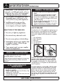 3
3
-
 4
4
-
 5
5
-
 6
6
-
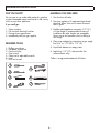 7
7
-
 8
8
-
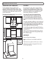 9
9
-
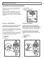 10
10
-
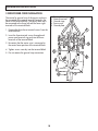 11
11
-
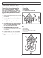 12
12
-
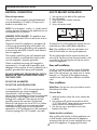 13
13
-
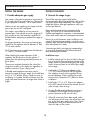 14
14
-
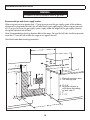 15
15
-
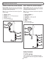 16
16
-
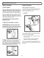 17
17
-
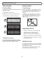 18
18
-
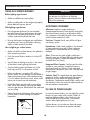 19
19
-
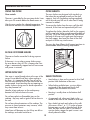 20
20
-
 21
21
-
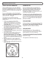 22
22
-
 23
23
-
 24
24
-
 25
25
-
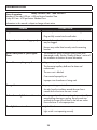 26
26
-
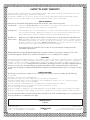 27
27
-
 28
28
-
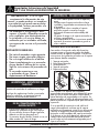 29
29
-
 30
30
-
 31
31
-
 32
32
-
 33
33
-
 34
34
-
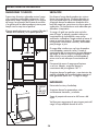 35
35
-
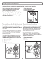 36
36
-
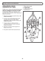 37
37
-
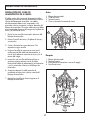 38
38
-
 39
39
-
 40
40
-
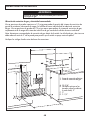 41
41
-
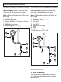 42
42
-
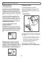 43
43
-
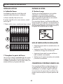 44
44
-
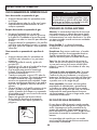 45
45
-
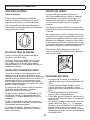 46
46
-
 47
47
-
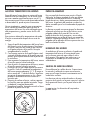 48
48
-
 49
49
-
 50
50
-
 51
51
-
 52
52
-
 53
53
-
 54
54


Danby DR202WGLP El manual del propietario
- Tipo
- El manual del propietario
en otros idiomas
- English: Danby DR202WGLP Owner's manual
Artículos relacionados
-
Danby DR240WGLPC El manual del propietario
-
Danby DER202BSS Manual de usuario
-
Danby DER202W El manual del propietario
-
-
Danby DR240WGLP El manual del propietario
-
Danby DR201BSSGLP Guía de instalación
-
Danby DERM240WC El manual del propietario
-
-
-
Unbranded DBTO0412BBSS El manual del propietario