
MULTI-HEAD PEX CRIMP TOOL KIT
#865896
INSTRUCTION GUIDE
CA865869INSTv3
DISTRIBUTED BY
RELIANCE WORLDWIDE CORPORATION 2727
Paces Ferry Road SE, Building II, Suite 1800,
A
tlanta, GA 30339 | T +1 877 700 4242
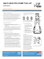
ADJUSTMENT PROCEDURE
CONNECTION ASSEMBLY
WARRANTY
CHECK ALL CRIMPS WITH GO/NO-GO GAGE
GAGING PROCEDURE
Cut the tube so that a clean, straight end is provided. Slide the crimp
ring over the tube end. Insert the tting into the tubing until the
shoulder of the tting contacts the tubing end. Position the crimp ring
1/8" to 1/4" (3.2 to 6.4 mm) from the cut end of the tubing.
Place the opened jaws of the PEX Crimp Tool around the crimp
ring. Check to be sure that the crimp ring is still properly positioned.
Compress the tool handles to complete the assembly.
1. Check tool calibration daily. It
is recommended that at least
the rst and last crimps of the
day are tested.
2. Never exceed the specied
handle distance when
adjusting your crimp tool.
Premature wear will result.
3. Lubricate linkages on a regular
basis to maximize tool life.
When properly maintained and used
as intended, the PEX Crimp Ring Tool
is warranted against materials and
manufacturing defects for a period
of 1 year from date of purchase.
This Warranty does not cover defects
or damage arising from improper
installation, lack of or improper
maintenance, improper storage or
handling, ordinary wear and tear,
misuse, abuse or accident,
or use with unauthorized tool or
parts. Liability is limited to repair or
replacement of tool or component
parts which are determined defective
as covered by this Warranty.
3/8", 1/2" AND 3/4" PEX INSERTS
(TOOL WITHOUT DIE SET CRIMPS 1")
1. Determine proper size of tubing: 3/8", 1/2", 3/4" or 1"
2. If GO cavity ts over crimped ring and NO-GO does not, tool is
crimping properly.
3. If GO cavity does not t then handle distance must be increased.
4. If GO ts—check NO-GO. If NO-GO ts over crimped ring,
the ring is over-crimped, decrease handle distance. Recheck.
NOTE: Over-crimped and under-crimped rings must be removed from
tubing. Crimp with a new copper ring.
1. Close tool handles until pre-load is reached (this is the point at
which jaws touch). Tool should not be completely closed.
2. Measure the distance between dots on the handle ends as shown.
8"– 8 3/4" is the correct distance. If the distance is not 8" – 8 3/4"
the tool must be adjusted.
3. To change the handle ends distance, remove the #6-32 eccentric
lock screw with an Allen wrench and push up eccentric from
back. Rotate eccentric counter-clockwise to increase the handle
distance and clockwise to decrease handle distance. Move
eccentric until hand distance is between 8" – 8 3/4". Push down
eccentric and re-install the #6-32 lock screw in the appropriate
hole which most closely yields the desired handle distance.
4. Recheck the set distance after making three crimps. The distance
should be 8" – 8 3/4" between the “dots” on the handles.
5. Check the crimps with the go/no-go gauge provided. If satisfactory
crimps do not result, the tool is likely worn and should be replaced.
United States: Oetiker, Inc. | 6317 Euclid Street
Marlette, Michigan 48453 | T +1 800 959 0398
Info.us.marlette@oetiker.com
www.oetiker.com
8"– 8 3/4"
HANDLE PRE-LOAD
“DOTS”
To insert/remove dies open tool fully
and push up plunger pin from back
side of tool.
TOOL MAINTENANCE
Eccentric
Lock
Screw
Gage all crimps as shown.
CRIMPS CONFORM TO ASTM F 1807

KIT DE ENGARZADORA PARA PEX
CON CABEZALES MÚLTIPLES
N. ̊ 865896
GUÍA DE INSTRUCCIONES
CA865869INSTv3
DISTRIBUIDO POR
RELIANCE WORLWIDE CORPORATION 2727
Pac
es Ferry Road SE, Building II, Suite 1800,
Atlanta, GA 30339 | T +1 877 700 4242
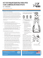
PROCEDIMIENTO DE AJUSTE
MONTAJE DE CONEXIONES
GARANTÍA
VERIFIQUE TODOS LOS ENGARCES CON UN CALIBRE DEL TIPO
PASA/NO PASA
PROCEDIMIENTO DE CALIBRACIÓN
Corte el tubo para que el extremo quede limpio y recto. Deslice el anillo de
engarce sobre el extremo del tubo. Inserte el accesorio dentro del tubo hasta que
el reborde del accesorio haga contacto con el extremo del tubo. Coloque el anillo
de engarce de 1/8" a 1/4" (3,2 a 6,4 mm) desde el extremo cortado del tubo.
Ubique las mordazas abiertas de la engarzadora para PEX alrededor del anillo de
engarce. Asegúrese de vericar que el anillo de engarce aún esté en la posición
correcta. Apriete el mango de la herramienta para completar el montaje.
1. Verique todos los días que la
herramienta esté calibrada. Se
recomienda someter a prueba
por lo menos el primer y último
engarce del día.
2. Al ajustar su engarzadora, nunca
exceda la distancia del mango
especicada. Si lo hace, provocará
un desgaste prematuro.
3. Lubrique periódicamente las
uniones para prolongar la vida útil
de la herramienta.
Siempre que se mantenga y utilice de la
forma prevista, la engarzadora para PEX
cuenta con una garantía de 1 año contra
defectos de fábrica y de los materiales,
a partir de la fecha de adquisición. Esta
garantía no cubre defectos ni daños
causados por instalación inadecuada,
falta de mantenimiento o mantenimiento
inapropiado, almacenamiento o manipulación
inadecuados, deterioro por uso normal,
uso indebido o abusivo, accidentes ni uso
con productos o piezas no autorizadas. La
responsabilidad se limita a la reparación o
reemplazo de la herramienta o de piezas
que la componen y determinadas como
defectuosas, según se cubran en esta garantía.
INSERTOS DE PEX DE 3/8", 1/2" Y 3/4"
(HERRAMIENTA SIN JUEGO DE TROQUELES
CON ENGARCES DE 1")
1. Determine el tamaño adecuado del tubo: 3/8", 1/2", 3/4" o 1"
2. Si el oricio del tipo PASA encaja en el anillo de engarce y el del tipo NO
PASA no, la herramienta está engarzando correctamente.
3. Si el oricio del tipo PASA no encaja, se debe aumentar la distancia del mango.
4. Si el oricio del tipo PASA encaja, verique el del tipo NO PASA. Si el
oricio del tipo NO PASA encaja en el anillo de engarce, está demasiado
engarzado. Reduzca la distancia del mango. Vuelva a vericar.
NOTA: Los anillos demasiado engarzados o los que no estén sucientemente
engarzados deben retirarse del tubo. Engarce con un anillo de cobre nuevo.
1. Cierre el mango de la herramienta hasta alcanzar el estado previo a la
carga (es el punto en el que se tocan las mordazas). La herramienta no
debe cerrarse por completo.
2. Mida la distancia entre los puntos que se encuentran en los extremos del
mango, como se muestra en la imagen. La distancia correcta es de 8" a
8 3/4". Si la distancia no es de 8 a 8 3/4", se debe ajustar la herramienta.
3. Para cambiar la distancia de los extremos del mango, retire el tornillo
de bloqueo del excéntrico N. ̊ 6-32 con una llave Allen y levante el
excéntrico desde atrás. Gire el excéntrico hacia la izquierda para
aumentar la distancia del mango y hacia la derecha para reducirla.
Mueva el excéntrico hasta que la distancia del mango esté entre 8 y 8
3/4". Empuje el excéntrico hacia abajo y vuelva a instalar el tonillo de
bloqueo N. ̊ 6-32 en el oricio adecuado que genere la distancia del
mango que más se acerque a la deseada.
4. Vuelva a vericar la distancia congurada luego de realizar tres
engarces. La distancia debería ser de 8 a 8 3/4" entre los “puntos”
que se encuentran en los mangos.
5. Verique los engarces con el calibre del tipo pasa/no pasa que se
incluye. Si los engarces obtenidos no son satisfactorios, es probable
que la herramienta esté desgastada y deba reemplazarse.
United States: Oetiker, Inc. | 6317 Euclid Street
Marlette, Michigan 48453 | T +1 800 959 0398
Info.us.marlette@oetiker.com
www.oetiker.com
8"– 8 3/4"
MANGO PREVIO A LA CARGA
“PUNTOS”
Para insertar o retirar los troqueles, abra la
herramienta del todo y levante el pasador
del émbolo desde atrás de la herramienta.
MANTENIMIENTO DE
LA HERRAMIENTA
Excéntrico
Traba
Tornillo
Calibre todos los engarces
como se muestra en la imagen.
LAS ENGARZADORAS CUMPLEN CON LAS ESPECIFICACIONES DE ASTM F 1807
-
 1
1
-
 2
2


en otros idiomas
- English: SharkBite 24693Z User manual
Artículos relacionados
Otros documentos
-
Viega PureFlow 1119 Product Instructions
-
Greenlee HK12ID Dieless Crimping Tool Manual de usuario
-
ABB Smart Tool + Manual de usuario
-
Greenlee 52087647 REV0 Manual de usuario
-
-
Milwaukee M18 FORCE LOGIC 2877-20 Manual de usuario
-
IAM Design EF7X705/50 Guía de instalación