Remington REM-140T-KFA-O Manual de usuario
- Tipo
- Manual de usuario

MODEL NUMBERS:
REM-45-KFA-O / REM-80T-KFA-O / REM-140T-KFA-O / REM-190T-KFA-O / REM-215T-KFA-O
CONSUMER: READ AND SAVE THESE INSTRUCTIONS
GENERAL HAZARD WARNING: READ AND UNDERSTAND
ALL OF THE INSTRUCTIONS IN THIS MANUAL BEFORE
ASSEMBLING, STARTING, OR SERVICING THE HEATER. Be
sure to comply with the instructions and warnings provided with this heater. Failure to
comply can result in re or explosion that can cause property loss, bodily injury, or loss
of life. Only persons who can follow and understand these instructions should operate or
service this heater. If you need heater info; such as an operating manual, labels, etcetera,
contact Pinnacle Climate Technologies at 866-676-1989.
DANGER
NOT FOR USE IN RESIDENTIAL LIVING AREAS OR IN
ENCLOSED SPACES WITHOUT ADEQUATE VENTILATION.
FOR OUTDOOR USE. INDOOR USE PERMITTED ONLY
FOR: THE TEMPORARY HEATING OF ADEQUATELY VENTILATED BUILDINGS OR
STRUCTURES UNDER CONSTRUCTION, ALTERATION OR REPAIR. This is an unvented
portable heater that uses air (Oxygen) from within the area in which it is used. Failure
to provide adequate combustion and ventilation air will result in asphyxiation, carbon
monoxide poisoning, bodily injury or death. Refer to “Ventilation” on Page 6.
FACTORY ID: 001
DANGER
1 Industrial Blvd #101, Sauk Rapids, MN 56379 USA • Toll Free (866) 676-1989
Fax: 320-251-2922 • Web: www.remingtonheater.com • Email: [email protected]
© 2018 Pinnacle Climate Technologies, Inc.
RGKI-403
User’s Manual &
Operating Instructions
KEROSENE FORCED AIR HEATER
Locating Your Serial Number:
Your serial number can be found on a white label on the right side cover of your heater. For Exam-
ple: 150812779. Have your Serial Number ready before calling customer service at 866-676-1989.

NEVER LEAVE HEATER UNATTENDED WHILE BURNING
OR WHILE CONNECTED TO A POWER SOURCE
© 2018 Pinnacle Climate Technologies, Inc. Kerosene Forced Air Heater User’s Manual
2
MASSACHUSETTS RESIDENTS: Massachusetts state law prohibits the use of this heater
in any building which is used in whole or in part for human habitation. Use of this heating
device in Massachusetts requires local re department permit (M.G.L.C. 148, Section 10A).
NEW YORK CITY RESIDENTS: The New York City Fire Code prohibits the storage, handling
and use of kerosene fueled heaters for space heating. Any person violating that provision
may be punished by a ne up to $10,000 and a term of imprisonment of up to 6 months.
Look for this icon throughout the manual for helpful tips on how to assemble, use
and clean your KFA Heater.
THE INSTALLATION OF THE EQUIPMENT SHALL BE IN ACCORDANCE WITH THE
REGULATION OF AUTHORITIES HAVING JURISDICTION AND CSA STANDARD B139.
This product contains chemicals, including lead, which are known to the
State of California to cause cancer and birth defects or other reproductive
harm. For more information go to www.P65Warnings.ca.gov.
DO NOT START THE HEATER WHEN EXCESS OIL HAS ACCUMU-
LATED.
DO NOT START THE HEATER WHEN THE CHAMBER IS HOT.
WARNING
WARNING
WARNING
FIRE, BURN, INHALATION AND EXPLOSION HAZARD. Keep
combustibles such as; building materials, paper or cardboard a safe
distance away from the heater as recommended by these instruc-
tions. Never use the heater in spaces which contain products such as; gasoline, solvents, paint
thinners, dust particles, volatile or airborne combustibles or any unknown chemicals. This is
an unvented portable heater. It uses air (Oxygen) from the area in which it is used. Adequate
combustion and ventilation air must be provided. Refer to “Ventilation” on page 6. Bulk fuel
storage should be a minimum of 25 feet (7.6 m) from heater.
WARNING
DO NOT OPERATE THIS HEATER UNTIL YOU HAVE READ
AND THOROUGHLY UNDERSTAND THESE SAFETY AND OP-
ERATING INSTRUCTIONS.
Failure to comply with the precautions and instructions provided with
this heater can result in death, serious bodily injury, property loss or damage from the hazards of
re, soot production, explosions, burns, asphyxiation or carbon monoxide poisoning. Only per-
sons who can read and understand these instructions should use or service this heater.
WARNING
SAFETY INFORMATION
Safety Information............................................2-3
What’s in the Box................................................4
Specications......................................................5
Features..
...........................................................
5
Assembly Instructions.........................................5
Opeation...........................................................6-7
Maintenance.....................................................8-9
Wiring Diagrams................................................10
Troubleshooting Guide......................................11
Exploded View
............................................
...
.
.12
Parts List............................................................13
Limited Warranty...............................................14
TABLE OF CONTENTS

NEVER LEAVE HEATER UNATTENDED WHILE BURNING
OR WHILE CONNECTED TO A POWER SOURCE
© 2018 Pinnacle Climate Technologies, Inc. Kerosene Forced Air Heater User’s Manual
3
SAFETY INFORMATION (CONT.)
ALWAYS use only the electrical power (voltage and
frequency) specied on the model plate of the heater.
ALWAYS use only three-prong, grounded outlet and
extension cord.
ALWAYS use only 14 AWG or better extension cord.
ALWAYS unplug the heater when not in use.
ALWAYS install the heater so that it is not directly
exposed to water spray, rain, dripping water, or
wind.
NEVER use fuels such as gasoline, benzine, paint
thinners or other oil compounds in this heater.
NEVER rell the heater’s fuel tank while the heater is
operating or still hot. This heater is EXTREMELY HOT
while in operation.
NEVER block air inlet (rear) or air outlet (front).
NEVER use duct work in front or rear of heater.
NEVER move or handle heater while still hot.
NEVER transport heater with fuel in tank.
NEVER use with an external fuel tank.
Keep all combustible materials away from this heater.
Minimum Clearance From Combustibles
45-190T-KFA 215T-KFA
Top
4 ft. (125 cm) 4 ft. (125 cm)
Sides
4 ft. (125 cm) 4 ft. (125 cm)
Front
8 ft. (250 cm) 10 ft. (305 cm)
ALWAYS locate heater on a stable and level surface.
If your heater is equipped with a thermostat, once
it is plugged in, it can start at anytime in accordance
with the thermostat setting.
RISK OF BURNS,
FIRE AND
EXPLOSION!
RISK OF ELECTRIC
SHOCK!
WARNING
WARNING
CAUTION! HOT
WHILE IN OPERA-
TION. DO NOT
TOUCH. KEEP CHILDREN, ANIMALS,
CLOTHING AND COMBUSTIBLES AWAY
FROM HEATER.
WARNING
The products described in this manual are
kerosene direct-red, forced air heaters.
Kerosene forced air heaters are primarily
intended for use for temporary heating of
buildings under construction, alteration or repair.
Direct-red means that all of the combustion
products of the heater enter the heated space.
This appliance is rated at 98% combustion
efciency, but does produce small amounts of
carbon monoxide.
Carbon monoxide is toxic. Humans can tolerate
only small amounts of carbon monoxide and so
precautions should be taken to provide proper
ventilation. Failure to provide proper ventilation in
accordance with the instructions in this manual can
result in death. People with breathing problems
should consult a physician before using this
heater. Early signs of carbon monoxide poisoning
resemble the u. Symptoms of improper
ventilation/carbon monoxide poisoning are:
Headache • Dizziness • Nausea • Dry Mouth
Sore Throat • Burning of Nose and Eyes
If you experience any of these symptoms:
GET FRESH AIR AT ONCE! Have your heater
serviced and check for proper ventilation. Some
people are more affected by carbon monoxide than
others. These include: pregnant women, those with
heart or lung problems, anemia or those under the
inuence of alcohol or at high altitudes.
FOR OUTDOOR USE. INDOOR USE
PERMITTED ONLY FOR: The temporary
heating of adequately ventilated buildings
or structures under construction, alteration
or repair. Provide at least a three square
foot (2,800 sq cm) opening of outside air for
every 100,000 Btu/Hr (29 kW) heater rating.
Refer to “Ventilation” on page 6 for further
instructions.
RISK OF INDOOR
AIR POLLUTION!
WARNING
CARBON
MONOXIDE
POISONING MAY
LEAD TO DEATH!
DANGER

NEVER LEAVE HEATER UNATTENDED WHILE BURNING
OR WHILE CONNECTED TO A POWER SOURCE
© 2018 Pinnacle Climate Technologies, Inc. Kerosene Forced Air Heater User’s Manual
4
WHAT’S IN THE BOX (45-KFA / 80T-KFA)
- Remove the heater and all packaging materials
from the shipping carton
Note: Save the box and packaging materials
for future storage.
Shown With Optional Cord
Wraps
Cord Wraps (Optional)
Carry Handle (1)
10 mm Screws (2)
WHAT’S IN THE BOX (140T-KFA / 175T-KFA / 215T-KFA)
Tip: Be sure to remove the axle from the side of
the Styrofoam packaging.
Front Handle
Axle
Rear Handle
Bottom Skid
Wheels (2)
Axle Nuts (2)
Spacers (2)
Heater (1)
Heater (1)
Axle Supports
15 mm Screws (2)

NEVER LEAVE HEATER UNATTENDED WHILE BURNING
OR WHILE CONNECTED TO A POWER SOURCE
© 2018 Pinnacle Climate Technologies, Inc. Kerosene Forced Air Heater User’s Manual
5
ASSEMBLY INSTRUCTIONS (140T-KFA / 175T-KFA / 190T-KFA / 215T-KFA)
1. Tilt the heater tank backward and attach the bot-
tom skid by inserting the skid into the button
spring clips at the front of the bottom support
frame.
2. Attach the axle supports by inserting them into
the button spring clips at the rear of the bottom
support frame.
3. Insert the axle through the holes in the axle sup-
ports.
4. Slide the spacers onto the axle.
5. Slide the wheels onto the axle and secure with the
axle nuts.
6. Attach the front handle by inserting the handle
into the button spring clips at the front of the top
support frame.
7. Attach the rear handle by inserting the handle
into the button spring clips at the rear of the top
support frame.
8. Check all parts to ensure they are secure before
operating the heater.
SPECIFICATIONS
Model # 45-KFA 80T-KFA
140T-KFA 190T-KFA 215T-KFA
Rating: Btu/Hr 45,000 80,000 140,000 190,000 215,000
Fuel Consumption: Gal/Hr 0.35 0.63/2.38 1.1/4.16 1.42 1.63
Fuel Tank Capacity: Gallons
5 5 10 13 13
Pump Pressure: psi 3.0 3.8 6.6 8.5 9.0
Volts: AC/Hz
120VAC / 60Hz 120VAC / 60Hz 120VAC / 60Hz 120VAC / 60Hz 120VAC / 60Hz
Amps 1.4 1.5 2.4 2.7 2.8
Phase Single Single Single Single Single
Specications subject to change without notice.
FEATURES
Hot Air Outlet
Upper Shell
Handle
Extension Cord Wrap
Fan Guard
Pressure Gauge
Fuel Gauge
Fuel Cap
Power Cord
Fuel Tank
Power/Reset Switch
Thermostat Knob
(80T KFA Only)
Lamp
Lower Shell
Upper Shell
Power
Cord
Drain Bolt
Fuel Tank
Pressure
Gauge
Fan Guard
Rear Handle
Digital Tempera-
ture Display
Lamp
Thermostat Knob
Fuel Cap
Fuel Gauge
Lower Shell
Hot Air
Outlet
Front
Handle
Figure 1
Axle
Axle Nut
Spacer
Tire
Axle Support

NEVER LEAVE HEATER UNATTENDED WHILE BURNING
OR WHILE CONNECTED TO A POWER SOURCE
© 2018 Pinnacle Climate Technologies, Inc. Kerosene Forced Air Heater User’s Manual
6
Fueling The Heater:
Kerosene (K-1)
For optimal performance of this heater, it is
strongly suggested that K-1 kerosene be used,
especially in temperatures lower than 26°F
(-3°C). K-1 kerosene has been rened to virtually
eliminate contaminants, such as sulfur, which can
cause a rotten egg odor during the operation
of the heater. Using diesel fuel can cause excess
soot production. Do not use Bio-Diesel as this
fuel will damage your heater’s seals and lter.
- CSA certified for use with K-1 kerosene, no.
1 & no. 2 diesel, JP8/Jet A Fuel, no. 1 and no.
2 fuel oil.
DO NOT use any fuel that is not approved
above.
- NEVER use fuel such as, benzene, alcohol, white
glass, camp stove fuel, paint thinners, or other oil
compounds in this heater. THESE ARE VOLATILE
FUELS THAT CAN CAUSE A FIRE OR EXPLOSION.
- NEVER store kerosene in the living space. Kerosene
should be stored in a well ventilated area outside
the living area.
- NEVER store kerosene in direct sunlight or near a
source of heat.
- NEVER use kerosene that has been stored from
one season to the next. Kerosene deteriorates
over time. OLD KEROSENE WILL NOT BURN
PROPERLY IN THIS HEATER.
NOTE: Kerosene should only be stored in a blue
container that is clearly marked “Kerosene.”
Never store kerosene in a red container. Red is
associated with gasoline.
Ventilation:
- Risk of indoor air pollution and Carbon
Monoxide Poisoning. Use heater only in well
ventilated areas.
- Refer to Safety Information on page 3 for
information about Carbon Monoxide
Poisoning.
- ALWAYS provide a fresh air opening in the heated
space of at least three square feet (2,800 sq. cm)
for each 100,000 Btu / Hr. (29 kW) of heater
output. Provide a larger opening if more heaters
are being used.
Minimum Ventilation Opening Needed
45-KFA 80T-KFA 140T-KFA
1.4 ft.² 2.4 ft.² 4.2 ft.²
1250 cm² 2230 cm² 3902 cm²
Minimum Ventilation Opening Needed
190T-KFA 215T-KFA
5.7 ft.
2
6.5 ft.²
5290 cm
2
5990 cm²
OPERATION
NEVER FILL
THE FUEL TANK
INDOORS. AL-
WAYS FILL THE TANK OUTDOORS. BE
SURE THAT THE HEATER IS ON LEVEL
GROUND WHEN FUELING, AND NEVER
OVERFILL THE TANK.
CAUTION
CARBON MONOXIDE POISONING MAY
LEAD TO DEATH!
DANGER
DO NOT USE
GASOLINE OR
CRANKCASE
DRAININGS.
WARNING
NEVER REFUEL
THIS HEATER
WHILE IT IS HOT
OR OPERATING. FIRE OR EXPLOSION
COULD RESULT.
DANGER

NEVER LEAVE HEATER UNATTENDED WHILE BURNING
OR WHILE CONNECTED TO A POWER SOURCE
© 2018 Pinnacle Climate Technologies, Inc. Kerosene Forced Air Heater User’s Manual
7
OPERATION (CONT.)
Starting the Heater: (Ignition)
1. Fill the tank with kerosene or other approved
fuel until needle on fuel gauge points to “F”.
2. Replace fuel cap and tighten rmly.
3. Connect the heater to a three prong
(grounded) power source. You must use a
three prong (grounded) extension cord that
is at least 6 feet long and is a minimum of 14
AWG rating.
Model 45-KFA:
1. Complete steps 1-3 above.
2. Move power switch to “On” position. The
power indicator light will illuminate and the
heater will ignite.
Stopping / Restarting Heater:
- To stop the heater, move the power switch to the
“Off” position and unplug the power cord.
- To restart the heater; wait 10 seconds and follow
ignition steps.
Models 80T-KFA - 215T-KFA:
1. Complete “starting heater ignition” steps 1-3
above
2. Turn thermostat control knob to desired
temperature setting. The thermostat set range
is from 40 ºF to 110 ºF.
3. Move power switch to “On” position. The
power indicator light and room temperature
display will illuminate and heater will ignite.
NOTE: 45-80T-KFA models do not have a room
temperature display feature.
The room temperature display will indicate the
following:
- When the temperature is less than 0 ºF the
display says “LO”.
- When the temperature is more that 99 ºF the
display says “HI”.
- Between 0 F and 99 F the display shows actual
temperature.
Stopping / Restarting Heater:
- To stop the heater, move the power switch to the
“Off” position and unplug the power cord.
- To restart the heater; wait 10 seconds and follow
ignition steps.
Long Term Storage:
Models 45-KFA - 80T-KFA:
1. Use an approved siphon to drain fuel through the
fuel cap opening.
Models 140T-KFA - 215T-KFA:
1. Drain fuel through the drain bolt in the bottom
of the fuel tank.
2. To remove the drain bolt, unscrew
counterclockwise.
3. Using a small amount of kerosene, rinse and
swirl the kerosene inside of the fuel tank,
empty the tank fully.
4. To replace the drain bolt; push the drain head
fully into the drain hole and screw clockwise.
IMPORTANT: Never store leftover kerosene
between seasons, using old fuel can damage
heater.
TIP: If the heater does not ignite; move
switch to “Off” position, check steps 1-3
above and then move switch to “On” position.
TIP: If the heater does not ignite, the
thermostat may be set too low. Turn the
control knob to a higher setting until the heater
ignites. If the heater does not ignite; move switch
to “Off” position, check steps 1-3 above and then
move switch to “On” position.

NEVER LEAVE HEATER UNATTENDED WHILE BURNING
OR WHILE CONNECTED TO A POWER SOURCE
© 2018 Pinnacle Climate Technologies, Inc. Kerosene Forced Air Heater User’s Manual
8
MAINTENANCE
Service:
DO NOT TAMPER WITH THE UNIT. HAVE
A COMPETENT SERVICEMAN MAKE ANY
NECESSARY ADJUSTMENT OR REPAIRS.
Use only original equipment parts. The use of
alternate or third party components can cause
unsafe operating conditions and will void your
warranty.
We suggest following a maintenance schedule as follows:
FUEL / FUEL TANK:
Flush tank every 200 hours of operation or as needed.
DO NOT ush with water; use fresh K-1 kerosene only.
AIR FILTERS:
The air intake lter should be replaced or washed
with soap and water and dried thoroughly every 500
hours of operation or less depending on conditions.
The output and lint lters should be replaced
every 500 hours of operation or less depending on
conditions (See Figure 3).
NOTE: Use of diesel fuel may require additional
maintenance
FAN BLADES:
Blades should be cleaned at least once per
heating season, depending on conditions.
Remove all accumulated dust and dirt with a
damp cloth, taking care not to bend any of the
fan blades. Be sure the blades are dry before
re-starting the heater.
FUEL FILTER:
The fuel filter should be cleaned at least twice
per heating season. Clean the filter by rinsing it in
clean K-1 Kerosene. Contaminated fuel could make
cleaning the fuel filter necessary immediately.
NOTE: To remove the filter from models 45 -
80T-KFA turn filter 90º clockwise. To remove the
filter from models 140T - 215T-KFA turn filter
90º counter-clockwise. See Figure 2.
THERMISTER PLACEMENT:
Ensure the thermister wire is in the proper place.
The wire should be lying on the bottom shell
inside the heater with the plastic end placed
under the motor support/motor and away from
fan blade.
ROTOR:
The rotor with carbon vanes should be evaluated
every heating season. The rotor is behind the air
filters. The vanes should be inspected for damage
or wear. The rotor should be inspected for
damage, chips, wear, cracks.
Check rotor gap: Remove the rear cover. Loosen
the two pump ring screws. Lift the pump ring
upwards. Insert a 0.1 mm feeler gauge and
apply slight downward pressure, enough to offer
resistance when attempting to remove gauge.
Hand-tighten the two pump ring screws. Re-install
the End Pump Cover and the plastic End Filter
Cover. Start the heater and adjust to the proper
pump pressure.
Air Output Filter
Intake Filter
Lint Filter End Filter
Figure 3
Never service
heater while it is
plugged in or hot!
WARNING
Figure 2
Fuel Filter
Fuel Line
Side Cover

NEVER LEAVE HEATER UNATTENDED WHILE BURNING
OR WHILE CONNECTED TO A POWER SOURCE
© 2018 Pinnacle Climate Technologies, Inc. Kerosene Forced Air Heater User’s Manual
9
X
X
MAINTENANCE (CONT.)
Service (Continued):
SPARK PLUG:
Clean and re-gap every 600 hours of operation, or
replace as needed. After removing the spark plug,
clean the terminals with a wire brush. Re-gap the
terminals to 0.140” (3.5mm). See Figure 4.
PHOTOCELL:
The photocell should be cleaned using a cotton
swab dipped in alcohol or water at least once per
heating season, or more depending on conditions.
See Figure 5.
PUMP PRESSURE:
While heater is operating, turn adjusting screw
clockwise to increase, counter-clockwise to
decrease pressure. Correct pump pressure is as
follows:
Model Number Pump Pressure
45-KFA 3.0 PSI (0.21 BAR)
80T-KFA 3.8 PSI (0.26 BAR)
140T-KFA 6.6 PSI (0.46 BAR)
190T-KFA 8.5 PSI (0.59 BAR)
215T-KFA 9.0 PSI (0.62 BAR)
Tolerance ± 10%
NOZZLES:
Nozzles should be cleaned or replaced at least
once per heating season. Contaminated fuel could
make this necessary immediately. To clean dirt
from nozzle, blow compressed air through nozzle
front. It may be necessary to soak the nozzle in K-1
kerosene to loosen any dirt particles.
Figure 4
Ignitor Wire
Spark Plug
Gap
Burner Head
Figure 5
Photocell
Photocell lens
Photocell
Wire
Figure 6
Adjusting Screw
Pressure Valve
Figure 7
Nozzle
Nozzle Face
Burner Head

NEVER LEAVE HEATER UNATTENDED WHILE BURNING
OR WHILE CONNECTED TO A POWER SOURCE
© 2018 Pinnacle Climate Technologies, Inc. Kerosene Forced Air Heater User’s Manual
10
WIRING DIAGRAMS
(80T-KFA)
(140T-KFA)
(175T-KFA / 190T-KFA / 215T-KFA)
Models
140T/175T/190T/215T-KFA have
a digital display.
80T-KFA
140T-KFA / 175T-KFA / 190T-KFA
45-KFA
80T - 215T-
KFA

NEVER LEAVE HEATER UNATTENDED WHILE BURNING
OR WHILE CONNECTED TO A POWER SOURCE
© 2018 Pinnacle Climate Technologies, Inc. Kerosene Forced Air Heater User’s Manual
11
TROUBLESHOOTING GUIDE
Problem Possible Cause Solution
Heater Ignites, but main PCB shuts
off after a short period of time.
Lamp ickers and LED display
shows “E1”.
1. Incorrect pump pressure.
2. Dirty input, output or lint lter.
3. Dirty fuel lter.
4. Nozzle is dirty.
5. Photocell lens is dirty.
6. Photocell not installed properly.
7. Photocell is defective.
8. Improper electrical connection
between main PCB and photocell.
9. Improper location of thermister
sensor (does not apply to 45-KFA
model)
10. Improper electrical connection within
the temperature limit switch
1. Adjust pump pressure.
2. Clean / replace air or lint lter.
3. Clean / replace fuel lter.
4. Clean / replace Nozzle.
5. Clean / replace photocell.
6. Adjust photocell position
7. Replace photocell
8. Check wiring connections
(see wiring diagrams on page 10).
9. Check thermister placement
10. Replace temperature limit switch
Heater will not operate or motor
runs for a short time.
Lamp ickers and LED display
shows “E1”.
1. No kerosene in the fuel tank.
2. Incorrect pump pressure.
3. Corroded spark plug or incorrect
plug gap.
4. Dirty fuel lter.
5. Dirty nozzle.
6. Moisture in fuel tank.
7. Improper electrical connection
between transformer and circuit
board.
8. Ignitor wire not connected to
spark plug.
9. Defective ignitor.
10. Improper spacing with rotor
1. Fill tank with fresh kerosene.
2. Adjust pump pressure.
3. Clean / replace spark plug.
4. Clean / replace fuel lter.
5. Clean / replace nozzle.
6. Rinse fuel tank with clean, fresh
kerosene.
7. Inspect all electrical connections
(see wiring diagrams on page 10).
8. Re-attach ignitor wire to spark
plug.
9. Replace ignitor.
10. Adjust rotor
Fan does not operate when heater is
plugged in and power switch is in the
“ON” position. The lamp is ickering or
and LED display shows “E1” or “E2”.
1. Thermostat is set too low (does
not apply to 45-KFA model).
2. Broken electrical connection
between main PCB and motor.
1. Rotate thermostat to a higher
setting
2. Inspect all electrical connections
(see wiring diagrams on page 10).
Lamp is ickering and LED display
shows “E3”.
1. Thermostat switch has failed. 1. Replace thermostat switch (see
Wiring diagrams on page 10).
Poor combustion and / or excess
soot production.
1. Dirty input, output or lint lter.
2. Dirty fuel lter.
3. Poor quality of fuel.
4. PSI is too high or too low.
5. Dirty nozzle
1. Clean / replace air or lint lter.
2. Clean / replace fuel lter.
3. Flush fuel tank and refuel heater.
4. Use proper pressure.
5. Clean / replace nozzle
Heater does not turn on and the
lamp is not lit.
1. Temperature limit sensor has
overheated.
2. No electrical power.
3. Fuse is blown.
4. Improper electrical connection
between temperature limit sensor
and circuit board.
1. Push power switch to “OFF and
allow heater to cool for 10 minutes.
Restart heater.
2. Check power cords for proper
connection and test the power supply.
3. Check / replace the fuse.
4. Inspect all electrical connections
(see wiring diagrams on page 10).

NEVER LEAVE HEATER UNATTENDED WHILE BURNING
OR WHILE CONNECTED TO A POWER SOURCE
© 2018 Pinnacle Climate Technologies, Inc. Kerosene Forced Air Heater User’s Manual
12
13
10
12
8
11
9
29
25
3
15
2
4
6
1**
7
21
23
16
17
18
20
30
19
14
40**
32*
34**
35**
28
27
5
31
30
24
26
37**
36**
38**
33**
41
22
42**
43**
EXPLODED VIEW
* 45-KFA - 80T-KFA Only
** 140T-KFA - 215T-KFA Only

NEVER LEAVE HEATER UNATTENDED WHILE BURNING
OR WHILE CONNECTED TO A POWER SOURCE
© 2018 Pinnacle Climate Technologies, Inc. Kerosene Forced Air Heater User’s Manual
13
PARTS LIST
#
Description 45-KFA 80T-KFA 140T-KFA 190T-KFA 215T-KFA
1
Drain Bolt
–
–
70-002-0115 70-002-0115 70-002-0115
2
Fuel Gauge
70-007-0110 70-007-0110 70-007-0215 70-007-0215 70-007-0215
3
Fuel Filter
70-003-0100 70-003-0100 70-003-0200 70-003-0200 70-003-0200
4
Fuel Cap - Large Plastic
70-006-0140 70-006-0140 70-006-0140 70-006-0140 70-006-0140
5
Power Cord
70-034-0100 70-034-0100 70-034-0205 70-034-0205 70-034-0205
6
Power Switch
70-038-0100 70-038-0100 70-038-0100 70-038-0100 70-038-0100
7
Thermostat Control Knob
– 70-031-0100 70-031-0100 70-031-0100 70-031-0100
8
Air Line
70-035-0100 70-035-0200 70-035-0300 70-035-0400 70-035-0500
9
Thermostat Limit Control
70-019-0100 70-019-0100 70-019-0100 70-019-0100 70-019-0200
10 Photocell Bracket
70-010-0101 70-010-0101 70-010-0101 70-010-0101 70-010-0101
11 Fuel Line
70-036-1010 70-036-1010 70-036-1020 70-036-1030 70-036-1040
12 Photocell
70-016-0100 70-016-0100 70-016-0100 70-016-0100 70-016-0100
13 Burner Head Assembly
70-014-0101 70-014-0101 70-014-0301 70-014-0301 70-014-0301
14 Nozzle Kit
70-015-0100 70-015-0205 70-015-0310 70-015-0410 70-015-0500
15 Spark Plug Kit
70-052-0100 70-052-0100 70-052-0200 70-052-0200 70-052-0200
16 Motor
70-021-0500 70-021-0500 70-021-0510 70-021-0520 70-021-0520
17 Pump Body
70-020-0101 70-020-0101 70-020-0101 70-020-0401 70-020-0401
18
Rotor Kit
70-022-0100 70-022-0100 70-022-0100 70-022-0200 70-022-0200
19
End Pump Cover
70-020-0102 70-020-0102 70-020-0102 70-020-0102 70-020-0102
20
Filter Kit
70-054-0100 70-054-0100 70-054-0100 70-054-0100 70-054-0100
21
End Filter Cover
70-020-0103 70-020-0103 70-020-0103 70-020-0103 70-020-0103
22
Pump Adjustment Kit
70-055-0100 70-055-0100 70-055-0100 70-055-0100 70-055-0100
23
Capacitor
70-020-0125 70-020-0125 70-020-0200 70-020-0201 70-020-0201
24
Fan
70-024-0100 70-024-0200 70-024-0300 70-024-0400 70-024-0400
25
Ignitor
70-037-0350 70-037-0350 70-037-0350 70-037-0350 70-037-0350
26
Fan Guard
70-016-0700 70-016-0700 70-016-0200 70-016-0200 70-016-0200
27
Main PCB Assembly
70-027-0100 70-027-0200 70-027-0300 70-027-0300 70-027-0300
28
Fuse
70-027-0101 70-027-0101 70-027-0101 70-027-0101 70-027-0101
29
Clip Nut
70-001-0106 70-001-0106 70-001-0106 70-001-0106 70-001-0106
30
Air Pressure Gauge
– 70-025-0100 70-025-0100 70-025-0100 70-025-0100
31
Cord Bushing
70-033-0100 70-033-0100 70-033-0200 70-033-0200 70-033-0200
32
Handle
70-001-0103 70-001-0103 – – –
33
Front Handle
– – 70-042-0810 70-042-0815 70-042-0815
34
Rear Handle
– – 70-043-0110 70-043-0600 70-043-0600
35
Wheel Support Frame
– – 70-041-0725 70-041-0740 70-041-0740
36
Wheel Axle
– – 70-041-0115 70-041-0205 70-041-0205
37
Wheel
– – 70-041-1400 70-041-1400 70-041-1400
38
Wheel Nut
– – 70-041-0550 70-041-0550 70-041-0550
39
Hardware Kit (not pictured)
70-056-0100 70-056-0100 70-056-0210 70-056-0210 70-056-0210
40
Cord Wrap
70-032-0100 70-032-0100 70-032-0200 70-032-0200 70-032-0200
41
Motor Supporter
70-020-0600 70-020-0600 70-020-0610 70-020-0610 70-020-0610
42
Axle Frame - Left
– – 70-041-0730 70-041-0745 70-041-0745
43
Axle Frame - Right
– – 70-041-0735 70-041-0750 70-041-0750

NEVER LEAVE HEATER UNATTENDED WHILE BURNING
OR WHILE CONNECTED TO A POWER SOURCE
© 2018 Pinnacle Climate Technologies, Inc. Kerosene Forced Air Heater User’s Manual
14
LIMITED WARRANTY
Pinnacle Climate Technologies, Inc. warrants this heater to
the original retail purchaser only, to be free from defects in
material and workmanship for a period of one (1) year from
the date of initial purchase. This product must be properly
installed, maintained and operated in accordance with the
instructions provided.
Pinnacle Climate Technologies, Inc. requires reasonable
proof of your date of purchase from an authorized retailer
or distributor. Therefore, you should keep your sales slip,
invoice or cancelled check from the original purchase.
This Limited Warranty shall be limited to the repair or
replacement of parts, which prove defective under normal
use and service within the warranty period, and which
Pinnacle Climate Technologies, Inc. shall determine at its
reasonable discretion.
This warranty does not apply to products purchased for
rental use.
This Limited Warranty does not cover any failures or
operating difculties due to normal wear and tear,
accident, abuse, misuse, alteration, misapplication,
improper installation or improper maintenance and service
by you or any third party. Failure to perform normal and
routine maintenance on the heater, shipping damage,
damage related to insects, birds or animals of any kind, and
damage due to weather conditions are also not covered.
In addition, the Limited Warranty does not cover damage
to the nish, such as scratches, dents, discoloration, rust or
other weather damage, after purchase.
All transportation costs for the return of damaged product
or parts will be the responsibility of the purchaser. Upon
receipt of damaged item, Pinnacle Climate Technologies,
Inc. will examine the item and determine if defective.
Pinnacle Climate Technologies, Inc. will repair or replace
and return the item, freight pre-paid.
If Pinnacle Climate Technologies, Inc. nds the item to be
in normal operating condition, or not defective the item
will be returned freight collect. This Limited Warranty is
in lieu of all other express warranties. Pinnacle Climate
Technologies, Inc. disclaims all warranties for products that
are purchased from sellers other than authorized dealers or
distributors.
AFTER THE PERIOD OF THE ONE (1) YEAR EXPRESS
WARRANTY EXPIRES, Pinnacle Climate Technologies,
Inc. DISCLAIMS ANY AND ALL IMPLIED WARRANTIES,
INCLUDING WITHOUT LIMITATION THE IMPLIED
WARRANTIES OF MERCHANTABILITY AND FITNESS
FOR A PARTICULAR APPLICATION. FURTHER, Pinnacle
Climate Technologies, Inc. SHALL HAVE NO LIABILITY
WHATSOEVER TO PURCHASER OR ANY THIRD PARTY
FOR ANY SPECIAL, INDIRECT, PUNITIVE INCIDENTAL,
OR CONSEQUENTIAL DAMAGES. Pinnacle Climate
Technologies, Inc. assumes no responsibility for any
defects caused by third parties. This Limited Warranty
gives the purchaser specic legal rights; a purchaser may
have other rights depending upon where he or she lives.
Some states do not allow the exclusion or limitation of
special, incidental or consequential damages, or limitations
on how long a warranty lasts, so the above exclusion and
limitations may not apply to you.
Pinnacle Climate Technologies, Inc. does not authorize
any person or company to assume for it any other
obligation or liability in connection with the sale,
installation, use, removal, return or replacement of its
equipment, and no such representations are binding on
Pinnacle Climate Technologies, Inc.
Always be sure to specify the model number and serial
number when making any claim with Pinnacle Climate
Technologies, Inc. For your convenience, use the space
provided below to list this information.
Model #:________________________________
Serial #:________________________________
Date of Purchase: ________________________
Locating Your Serial Number:
Your serial number can be found on a white label on the right side cover of your heater. It will be a
series of 9 digits. For Example: 131234956. Have your Serial Number ready befor
e calling customer
service at 866-676-1989.
Serial Number Label
XX-X-XXXXXX

MODELOS N.°
REM-45-KFA-O / REM-80T-KFA-O / REM-140T-KFA-O / REM-190T-KFA-O / REM-215T-KFA-O
CONSUMIDOR: LEA Y CONSERVE ESTAS INSTRUCCIONES
ADVERTENCIA GENERAL DE PELIGRO: LEA Y COMPRENDA
TODAS LAS INSTRUCCIONES EN ESTE MANUAL ANTES DE
ARMAR, ENCENDER O DAR SERVICIO AL CALENTADOR.
Asegúrese de seguir las instrucciones y advertencias provistas con este calentador. No seguirlas
puede provocar un incendio o explosión que pueden causar pérdidas materiales, lesiones físicas
o muerte. Solamente personas que puedan seguir y comprender estas instrucciones deben operar
o dar servicio a este calentador. Si necesita información sobre el calentador, como un manual de
operación, etiquetas, etc. comuníquese con Pinnacle Climate Technologies al 866-676-1989.
PELIGRO
ID DE FÁBRICA: 001
NO DEBE USARSE EN ÁREAS HABITABLES RESIDENCIALES NI
EN ESPACIOS CERRADOS CON VENTILACIÓN INADECUADA.
PARA USO EN EXTERIORES. EL USO EN INTERIORES SÓLO SE
PERMITE PARA: CALEFACCIÓN TEMPORAL DE EDIFICIOS ADECUADAMENTE VENTILADOS
O ESTRUCTURAS EN CONSTRUCCIÓN, MODIFICACIÓN O REPARACIÓN. Este es un
calentador portátil sin ventilación que utiliza aire (oxígeno) del área en la que se usa. Si no se
suministra aire de combustión y ventilación adecuados se puede causar asxia o envenenamiento
por monóxido de carbono, lesiones físicas o la muerte. Consulte “Ventilación” en la página 6.
PELIGRO
1 Industrial Blvd #101, Sauk Rapids, MN 56379, EE. UU. • Llamada sin costo: (866) 676-1989
Fax: 320-251-2922 • Web: www.remingtonheater.com • Correo electrónico: [email protected]
© 2018 Pinnacle Climate Technologies, Inc.
RGKI-403
Manual del usuario
e instrucciones de operación
CALENTADOR DE AIRE FORZADO
DE QUEROSENO
Cómo localizar su número de serie:
El número de serie lo puede encontrar en una etiqueta blanca en el lado derecho de la cubierta de
su calentador. Por ejemplo: 150812779. Tenga su número de serie a la mano antes de llamar al servicio
al cliente al 866-676-1989.

2
NUNCA DEJE DESATENDIDO EL CALENTADOR MIENTRAS ESTÉ ENCENDIDO
O MIENTRAS ESTÉ CONECTADO A UNA FUENTE DE ALIMENTACIÓN
© 2018 Pinnacle Climate Technologies, Inc. Manual del usuario del calentador
de aire forzado de queroseno
RESIDENTES DE MASSACHUSETTS: La ley del Estado de Massachusetts prohíbe el uso de
este calentador en cualquier edicio que se utilice total o parcialmente para habitación de seres
humanos. El uso de este dispositivo de calefacción en Massachusetts requiere la autorización del
departamento de bomberos de la localidad (M.G.L.C. 148, Sección 10A).
RESIDENTES DE LA CIUDAD DE NUEVA YORK: El Código de Incendios de la ciudad de Nueva
York prohíbe el almacenamiento, la manipulación y el uso de calentadores de queroseno para
calentar espacios. Toda persona que infrinja esa disposición estará sujeta a una multa de hasta
10,000 dólares y una sentencia de prisión de hasta 6 meses.
Busque este símbolo en el manual para encontrar consejos útiles sobre cómo armar, usar
y limpiar su calentador KFA.
LA INSTALACIÓN DEL EQUIPO DEBERÁ SER DE ACUERDO CON LOS REGLAMENTOS DE
LAS AUTORIDADES QUE TENGAN JURISDICCIÓN Y LA NORMA CSA B139.
NO ENCIENDA EL CALENTADOR CUANDO SE HAYA ACUMULADO
UN EXCESO DE ACEITE.
Este producto contiene sustancias químicas, incluyendo plomo, conocidas
en el estado de California como causantes de cáncer y defectos de nacimiento
u otros daños reproductivos. Si desea más información, visite
www.P65Warnings.ca.gov.
NO ENCIENDA EL CALENTADOR CUANDO LA CÁMARA ESTÁ CALIENTE.
PELIGRO DE INCENDIO, QUEMADURAS, INHALACIÓN Y EXPLOSIÓN.
Mantenga los combustibles como materiales de construcción, papel o
cartón, a una distancia prudente del calentador según lo recomiendan estas
instrucciones. Nunca use el calentador en espacios que contengan productos como gasolina, disolventes,
solventes de pintura, partículas de polvo, combustibles volátiles o suspendidos en el aire o sustancias
químicas desconocidas. Este es un calentador portátil sin ventilación. La unidad utiliza el aire (oxígeno)
del espacio donde se usa. Será necesario suministrar suciente aire para la combustión y la ventilación.
Consulte “Ventilación” en la página 6. El almacenamiento de combustible a granel debe estar a un mínimo
de 25 pies (7.6 m) del calentador.
NO USE ESTE CALENTADOR HASTA HABER LEÍDO Y COMPRENDIDO
TOTALMENTE ESTAS INSTRUCCIONES DE SEGURIDAD Y OPERACIÓN.
El no cumplir con las precauciones e instrucciones proporcionadas con este
calentador puede causar muertes, lesiones graves, pérdidas o daños materiales por el peligro de incendio,
producción de hollín, explosiones, quemaduras, asxia o envenenamiento por monóxido de carbono. Solamente
personas que puedan leer y comprender estas instrucciones deben usar o dar servicio a este calentador.
INFORMACIÓN DE SEGURIDAD
Información de seguridad ...................................... 2-3
Qué hay en la caja ..................................................... 4
Especicaciones ........................................................ 5
Características ........................................................... 5
Instrucciones de armado ........................................... 5
Funcionamiento ..................................................... 6-7
Mantenimiento ....................................................... 8-9
Diagramas eléctricos ............................................... 10
Guía para la solución de problemas ....................... 11
Vista detallada
........................................................
12
Lista de piezas ........................................................ 13
Garantía limitada ..................................................... 14
ÍNDICE

3
NUNCA DEJE DESATENDIDO EL CALENTADOR MIENTRAS ESTÉ ENCENDIDO
O MIENTRAS ESTÉ CONECTADO A UNA FUENTE DE ALIMENTACIÓN
© 2018 Pinnacle Climate Technologies, Inc. Manual del usuario del calentador
de aire forzado de queroseno
INFORMACIÓN DE SEGURIDAD (CONTINÚA)
SIEMPRE utilice la energía eléctrica (voltaje y frecuencia)
que se indica en la placa de modelo del calentador.
SIEMPRE use solamente tomacorrientes con conexión
a tierra y cable de extensión de tres puntas.
SIEMPRE utilice únicamente un cable de extensión
de calibre 14 AWG o superior.
SIEMPRE desconecte el calentador cuando no lo use.
SIEMPRE instale el calentador de modo que no esté
expuesto directamente a rocío de agua, lluvia, goteo de
agua o viento.
NUNCA use combustibles como gasolina, bencina,
solventes de pintura u otros compuestos de aceite en
este calentador.
NUNCA rellene el tanque de combustible del calentador
mientras esté en encendido o caliente. Este calentador
genera CALOR EXTREMO cuando está encendido.
NUNCA bloquee la entrada de aire (atrás) o la salida de
aire (al frente).
NUNCA use conductos en la parte frontal o posterior
del calentador.
NUNCA mueva ni manipule el calentador mientras esté
caliente.
NUNCA transporte el calentador con combustible
en el tanque.
NUNCA lo use con un tanque de combustible externo.
Mantenga todos los materiales combustibles lejos
de este calentador.
Separación mínima entre el calentador
y materiales combustibles
45-190T-KFA 215T-KFA
Superior
4 pies (125 cm) 4 pies (125 cm)
Lados
4 pies (125 cm) 4 pies (125 cm)
Frente
8 pies (250 cm) 10 pies (305 cm)
Colóquelo SIEMPRE sobre una supercie estable
y nivelada.
Si su calentador tiene un termostato, una vez que se
enchufe, puede encenderse en cualquier momento
según la conguración del termostato.
¡RIESGO DE
DESCARGA
ELÉCTRICA!
PRECAUCIÓN
CALIENTE
MIENTRAS ESTÉ EN
FUNCIONAMIENTO. NO LO TOQUE. MANTENGA
A NIÑOS, ANIMALES, ROPA Y COMBUSTIBLES
LEJOS DEL CALENTADOR.
Los productos descritos en este manual son
calentadores de aire forzado de fuego directo
de queroseno. Los calentadores de aire forzado
de queroseno están hechos expresamente para
calefacción temporal de edicios en construcción,
modicación o reparación. Fuego directo signica
que todos los productos de combustión del
calentador ingresan en el espacio calentado. Este
aparato tiene una clasicación de 98% de eciencia
de combustión, pero produce pequeñas cantidades
de monóxido de carbono.
El monóxido de carbono es tóxico. Los seres
humanos solo pueden tolerar pequeñas cantidades
de monóxido de carbono, así que deben tomarse las
medidas de precaución necesarias para suministrar
una ventilación adecuada. No proporcionar la
ventilación adecuada de acuerdo con este manual
puede ocasionar la muerte. Las personas con
problemas respiratorios deben consultar con un
médico antes de usar el calentador. Los primeros
síntomas de envenenamiento por monóxido de
carbono se parecen a los de la gripe. Los síntomas
de ventilación inadecuada o envenenamiento por
monóxido de carbono son:
Dolor de cabeza • Mareo • Náusea • Boca seca
Dolor de garganta • Irritación de la nariz y los ojos
Si tiene alguno de estos síntomas:
¡SALGA AL AIRE LIBRE DE INMEDIATO! Haga
revisar su calentador y compruebe que la ventilación
sea la adecuada. Algunas personas se ven más
afectadas que otras por el monóxido de carbono.
Por ejemplo: mujeres embarazadas, personas con
problemas pulmonares o cardíacos, anemia o bajo
la inuencia del alcohol o en grandes altitudes.
PARA USO EN EXTERIORES. EL USO EN
INTERIORES SÓLO SE PERMITE PARA:
Calefacción temporal de edificios adecuadamente
ventilados o estructuras en construcción,
modificación o reparación. Proporcione una
abertura de al menos tres pies cuadrados
(0.28 metros cuadrados) al aire exterior por cada
100,000 BTU/h (29 kWh) que genere el calentador.
Consulte “Ventilación” en la página 6 para obtener
más instrucciones.
¡RIESGO DE
CONTAMINACIÓN
DEL AIRE INTERIOR!
¡LA INTOXICACIÓN
POR MONÓXIDO
DE CARBONO
PUEDE CONDUCIR A LA MUERTE!
PELIGRO
¡RIESGO DE
QUEMADURAS,
INCENDIO Y
EXPLOSIÓN!

4
NUNCA DEJE DESATENDIDO EL CALENTADOR MIENTRAS ESTÉ ENCENDIDO
O MIENTRAS ESTÉ CONECTADO A UNA FUENTE DE ALIMENTACIÓN
© 2018 Pinnacle Climate Technologies, Inc. Manual del usuario del calentador
de aire forzado de queroseno
QUÉ HAY EN LA CAJA (45-KFA / 80T-KFA)
- Retire el calentador y los materiales de
empaque de la caja de envío
Nota: Guarde la caja y los materiales
de empaque para cuando guarde la
unidad posteriormente.
Ilustrado con enrolladores de
cable opcionales
Enrolladores de cable
(Opcional)
Asa (1)
Tornillos de 10 mm (2)
QUÉ HAY EN LA CAJA (140T-KFA / 175T-KFA / 215T-KFA)
Consejo: Asegúrese de retirar el eje del lateral
del empaque de espuma de poliestireno.
Asa delantera
Eje
Asa trasera
Patín inferior
Ruedas (2)
Tuercas del eje (2)
Separadores (2)
Calentador (1)
Calentador (1)
Soportes del eje
Tornillos de 15 mm (2)

5
NUNCA DEJE DESATENDIDO EL CALENTADOR MIENTRAS ESTÉ ENCENDIDO
O MIENTRAS ESTÉ CONECTADO A UNA FUENTE DE ALIMENTACIÓN
© 2018 Pinnacle Climate Technologies, Inc. Manual del usuario del calentador
de aire forzado de queroseno
INSTRUCCIONES DE ARMADO (140T-KFA / 175T-KFA / 190T-KFA / 215T-KFA)
1. Incline el tanque del calentador hacia atrás y je
el patín inferior insertándolo en los sujetadores
de resorte de botón al frente del marco de
soporte inferior.
2. Fije los soportes del eje insertándolos en los
sujetadores de resorte de botón en la parte
trasera del marco de soporte inferior.
3. Inserte el eje a través de los oricios en los
soportes del eje.
4. Deslice los separadores en el eje.
5. Deslice las ruedas en el eje y asegúrelas con las
tuercas del eje.
6. Fije el asa delantera insertándola en los
sujetadores de resorte de botón en el frente del
marco de soporte inferior.
7. Fije el asa trasera insertándola en los sujetadores
de resorte de botón en la parte trasera del marco
de soporte superior.
8. Verique todas las piezas para asegurar
que estén bien rmes antes de hacer funcionar
el calentador.
ESPECIFICACIONES
N.° de modelo 45-KFA 80T-KFA
140T-KFA 190T-KFA 215T-KFA
Capacidad nominal: Btu/H
45,000 80,000 140,000 190,000 215,000
Consumo de combustible: Gal/H
0.35 0.63/2.38 1.1/4.16 1.42 1.63
Capacidad del tanque: Galones
5 5 10 13 13
Presión de la bomba: psi
3.0 3.8 6.6 8.5 9.0
Voltaje: CA/Hz
120 VCA / 60 Hz 120 VCA / 60 Hz 120 VCA / 60 Hz 120 VCA / 60 Hz 120 VCA / 60 Hz
Amperaje
1.4 1.5 2.4 2.7 2.8
Fase
Monofásico Monofásico Monofásico Monofásico Monofásico
Las especicaciones pueden cambiar sin previo aviso.
CARACTERÍSTICAS
Salida de aire
caliente
Coraza superior
Asa
Enrollador de la extensión
Protección del
ventilador
Manómetro
Indicador de
combustible
Tapa de combustible
Cable eléctrico
Tanque de
combustible
Interruptor de
encendido/reinicio
Perilla del
termostato
(solo 80T KFA)
Luz
Coraza
inferior
Coraza superior
Cable eléctrico
Perno de drenaje
Tanque de
combustible
Manómetro
Protección
del ventilador
Asa trasera
Pantalla digital
de temperatura
Luz
Perilla del termostato
Tapa de
combustible
Indicador de
combustible
Coraza
inferior
Salida
de aire
caliente
Asa delantera
Figura 1
Eje
Tuerca
del eje
Separador
Llanta
Soporte del eje

6
NUNCA DEJE DESATENDIDO EL CALENTADOR MIENTRAS ESTÉ ENCENDIDO
O MIENTRAS ESTÉ CONECTADO A UNA FUENTE DE ALIMENTACIÓN
© 2018 Pinnacle Climate Technologies, Inc. Manual del usuario del calentador
de aire forzado de queroseno
Llenar de combustible el calentador:
Queroseno (K-1)
Para obtener un desempeño óptimo de este
calentador, se sugiere enfáticamente que se use
queroseno K-1, en especial a temperaturas por
debajo de 26 °F (-3 °C). El queroseno K-1 se ha
renado para eliminar virtualmente todos los
contaminantes, como el azufre, que pueden causar
un olor a huevos podridos durante el funcionamiento
del calentador. Usar combustible diésel puede
causar producción excesiva de hollín. No use Bio-
diésel pues dañará los sellos y el ltro del calentador.
- Certificado por CSA para uso con queroseno
K-1 y diésel N.º 1 y 2, combustible JP8/Jet A,
combustóleo N.º 1 y 2.
NO use ningún combustible que no se indique como
aprobado arriba.
- NUNCA use un combustible como bencina, alcohol,
gasolina blanca, combustible para hornos de
campamento, solventes de pintura u otros compuestos
de aceite en este calentador. ESTOS SON
COMBUSTIBLES VOLÁTILES QUE PUEDEN CAUSAR
INCENDIOS O EXPLOSIONES.
- NUNCA almacene queroseno en el área habitable.
El queroseno debe almacenarse en un área bien
ventilada, fuera del espacio habitable.
- NUNCA almacene el queroseno expuesto directamente
a la luz solar ni cerca de una fuente de calor.
- NUNCA utilice queroseno que haya estado almacenado
de una temporada a la siguiente. El queroseno se
deteriora con el tiempo. EL QUEROSENO VIEJO
NO SE QUEMARÁ ADECUADAMENTE EN
ESTE CALENTADOR.
NOTA: El queroseno debe almacenarse únicamente en
un contenedor azul que esté claramente identificado
con la palabra “queroseno”. Nunca almacene queroseno
en un contenedor rojo. El color rojo se asocia con
la gasolina.
Ventilación:
- Riesgo de contaminación del aire interior y de
envenenamiento por monóxido de carbono.
Utilice el calentador sólo en áreas bien ventiladas.
- Consulte la Información de seguridad en la página 3
acerca del envenenamiento por monóxido de
carbono.
- SIEMPRE provea una abertura para aire fresco en el
espacio que caliente por lo menos de tres pies
cuadrados (0.28 metros cuadrados) por cada
100,000 BTU/h (29 kWh) de emisión del calentador.
Si utiliza más calentadores, provea una abertura
más grande.
Abertura de ventilación mínima necesaria
45-KFA 80T-KFA 140T-KFA
1.4 pies² 2.4 pies² 4.2 pies²
1250 cm² 2230 cm² 3902 cm²
Abertura de ventilación mínima necesaria
190T-KFA 215T-KFA
5.7 pies
2
6.5 pies²
5290 cm
2
5990 cm²
FUNCIONAMIENTO
NUNCA LLENE
EL TANQUE DE
COMBUSTIBLE
EN UN LUGAR INTERIOR. SIEMPRE LLENE
EL TANQUE EN EXTERIORES. ASEGÚRESE
DE QUE EL CALENTADOR ESTÉ EN UN
SUELO NIVELADO CUANDO LLENE
DE COMBUSTIBLE, Y NUNCA LLENE
DEMASIADO EL TANQUE DE COMBUSTIBLE.
PRECAUCIÓN
¡LA INTOXICACIÓN POR MONÓXIDO DE
CARBONO PUEDE CONDUCIR A LA MUERTE!
PELIGRO
NO USE
GASOLINA O
ESCURRIMIENTOS
DEL CÁRTER
NUNCA LLENE
DE COMBUSTIBLE
ESTE
CALENTADOR MIENTRAS ESTÉ CALIENTE O EN
FUNCIONAMIENTO. ESO PUEDE OCASIONAR
UN INCENDIO O UNA EXPLOSIÓN.
PELIGRO

7
NUNCA DEJE DESATENDIDO EL CALENTADOR MIENTRAS ESTÉ ENCENDIDO
O MIENTRAS ESTÉ CONECTADO A UNA FUENTE DE ALIMENTACIÓN
© 2018 Pinnacle Climate Technologies, Inc. Manual del usuario del calentador
de aire forzado de queroseno
FUNCIONAMIENTO (CONTINÚA)
Encendido del calentador: (Ignición)
1. Llene el tanque de queroseno u otro combustible
aprobado hasta que el indicador de combustible
indique “F”.
2. Coloque la tapa de combustible y ajuste rmemente.
3. Conecte el calentador a una fuente de
alimentación de tres puntas (con conexión a
tierra). Debe usar un cable de extensión con tres
puntas (conectado a tierra) que tenga al menos
6 pies (1.8 m) de largo y clasicación mínima de
14 AWG.
Modelo 45-KFA:
1. Complete los pasos 1 a 3 descritos arriba.
2. Mueva el interruptor a la posición de encendido
(ON). La luz indicadora de energía se iluminará
y se encenderá el calentador.
Apagado / Reencendido del calentador:
-
Para apagar el calentador, mueva el interruptor
a la posición OFF (apagado) y desenchufe el
cable eléctrico.
- Para reencender el calentador, espere 10 segundos
y siga los pasos de ignición.
Modelos 80T-KFA / 215T-KFA:
1. Siga los pasos 1 a 3 de “Encendido del
calentador”.
2. Gire la perilla de control del termostato a la
temperatura deseada. El termostato varía entre
40 ºF y 110 ºF.
3. Mueva el interruptor a la posición de encendido
(ON). La luz indicadora de energía y la pantalla
de temperatura ambiente se iluminarán y se
encenderá el calentador.
NOTA: Los modelos 45-80T-KFA no tienen pantalla
de temperatura ambiente.
La pantalla de temperatura ambiente indicará
lo siguiente:
- Cuando la temperatura es inferior a 0 ºF (-18 ºC)
la pantalla mostrará “LO” (Baja).
- Cuando la temperatura es superior a 99 ºF (37 ºC)
la pantalla mostrará “HI” (Alta).
- Entre 0 °F (-18º C) y 99 °F (37 ºC) la pantalla mostrará
la temperatura real.
Apagado / Reencendido del calentador:
- Para apagar el calentador, mueva el interruptor
a la posición OFF (apagado) y desenchufe el
cable eléctrico.
- Para reencender el calentador, espere 10 segundos
y siga los pasos de ignición.
Almacenamiento a largo plazo:
Modelos 45-KFA / 80T-KFA:
1. Use un sifón aprobado para drenar el combustible
a través de la apertura de tapa de combustible.
Modelos 140T-KFA / 215T-KFA:
1. Drene el combustible a través del perno de
drenaje que está en la parte inferior del tanque
de combustible.
2. Para quitar el perno de drenaje, desatorníllelo
dando vuelta a la izquierda.
3. Con una pequeña cantidad de queroseno,
enjuague y haga girar el queroseno dentro del
tanque de combustible. Vacíe completamente
el tanque.
4. Para volver a instalar el perno de drenaje,
empuje el cabezal de drenaje totalmente en el
oricio de drenaje y atornille hacia la derecha.
IMPORTANTE: Nunca almacene el queroseno
sobrante entre temporadas. El uso de combustible
viejo puede dañar su calentador.
CONSEJO: Si el calentador no se
enciende, mueva el interruptor a la
posición de apagado (OFF), revise los pasos
1 a 3 anteriores y luego mueva el interruptor
a la posición de encendido (ON).
CONSEJO: Si el calentador no se enciende,
el termostato podría estar ajustado
demasiado bajo. Mueva la perilla de control a un
ajuste más alto hasta que encienda el calentador.
Si el calentador no se enciende, mueva el
interruptor a la posición de apagado (OFF),
revise los pasos 1 a 3 anteriores y luego mueva
el interruptor a la posición de encendido (ON).

8
NUNCA DEJE DESATENDIDO EL CALENTADOR MIENTRAS ESTÉ ENCENDIDO
O MIENTRAS ESTÉ CONECTADO A UNA FUENTE DE ALIMENTACIÓN
© 2018 Pinnacle Climate Technologies, Inc. Manual del usuario del calentador
de aire forzado de queroseno
MANTENIMIENTO
Servicio:
NO ALTERE LA UNIDAD. PIDA A UN TÉCNICO
COMPETENTE QUE HAGA LAS REPARACIONES
O AJUSTES NECESARIOS.
Utilice únicamente piezas de repuesto originales.
El uso de componentes alternativos o de terceros
puede causar condiciones peligrosas y anulará
su garantía.
Le sugerimos seguir un programa de mantenimiento
como el siguiente:
COMBUSTIBLE Y TANQUE DE COMBUSTIBLE:
Purgue el tanque después de cada 200 horas de
funcionamiento o según sea necesario. NO use agua
para purgar el tanque. Utilice únicamente queroseno
K-1 nuevo.
FILTROS DE AIRE:
El ltro de entrada de aire debe reemplazarse
o lavarse con agua y jabón y secarse completamente
cada 500 horas de funcionamiento o menos,
dependiendo de las condiciones.
Los ltros de salida y de pelusa deben reemplazarse
después de cada 500 horas de funcionamiento
o menos, dependiendo de las condiciones. (Vea
la Figura 3).
NOTA: Es posible que se necesite mantenimiento
adicional si se usa combustible diésel.
ASPAS DEL VENTILADOR:
Las aspas deben limpiarse al menos una vez por
cada temporada de calefacción, dependiendo de
sus condiciones. Limpie todas las acumulaciones de
polvo y suciedad con un trapo húmedo, teniendo
cuidado de no doblar ninguna de las aspas
del ventilador. Asegúrese de que las aspas del
ventilador estén secas antes de volver a encender
el calentador.
FILTRO DE COMBUSTIBLE:
El filtro de combustible debe limpiarse al menos dos
veces por cada temporada de calefacción. Enjuague
el filtro con queroseno K-1 limpio. El combustible
contaminado podría hacer que sea necesario limpiar
el filtro de combustible de inmediato.
NOTA: Para extraer el filtro de los modelos
45 - 80T-KFA, gire el filtro 90º
hacia la
derecha. Para extraer el filtro de los modelos
140T - 215T-KFA, gire el filtro 90º
hacia la
izquierda. Vea la Figura 2.
COLOCACIÓN DEL TERMISTOR:
Asegúrese de que el cable del termistor esté en el
lugar adecuado. El cable debe estar apoyado en la
parte inferior de la coraza dentro del calentador, con
el extremo de plástico colocado debajo del soporte
del motor/motor y alejado del aspa del ventilador.
ROTOR:
Evalúe el estado del rotor con álabes de carbono
cada temporada de calefacción. El rotor está detrás
de los filtros de aire. Inspeccione que los álabes no
estén dañados ni desgastados. Inspeccione que el
rotor no esté dañado, desportillado, desgastado,
ni agrietado.
Revise el espacio del rotor: Retire la cubierta
trasera. Afloje los dos tornillos del anillo de la
bomba. Levante el anillo de la bomba hacia arriba.
Inserte una lámina de ajuste de 0.1 mm y aplique
una ligera presión hacia abajo, lo suficiente para que
ofrezca resistencia al tratar de sacar la lámina.
Apriete con la mano los dos tornillos del anillo de la
bomba. Vuelva a instalar la cubierta de la bomba y la
cubierta de plástico del filtro. Encienda el calentador
y ajuste a la presión adecuada de la bomba.
Filtro de salida
de aire
Filtro de entrada
Filtro de pelusa Filtro del extremo
Figura 3
¡Nunca dé servicio al
calentador mientras
esté conectado
o caliente!
Figura 2
Filtro de combustible
Tubería de combustible
Cubierta
lateral

9
NUNCA DEJE DESATENDIDO EL CALENTADOR MIENTRAS ESTÉ ENCENDIDO
O MIENTRAS ESTÉ CONECTADO A UNA FUENTE DE ALIMENTACIÓN
© 2018 Pinnacle Climate Technologies, Inc. Manual del usuario del calentador
de aire forzado de queroseno
MANTENIMIENTO (CONT.)
Servicio (Continuación):
BUJÍA:
Límpiela y reajuste la separación entre los
electrodos de la bujía después de cada 600 horas de
funcionamiento o reemplácela según sea necesario.
Después de extraer la bujía, limpie las terminales
con un cepillo de alambre. Reajuste la separación de
las terminales a 0.140 pulg. (3.5mm). Vea la Figura 4.
FOTOCÉLULA:
La fotocélula debe limpiarse con un hisopo de
algodón remojado en agua o alcohol al menos
una vez por cada temporada de calefacción o más,
según las condiciones en que esté. Vea la Figura 5.
PRESIÓN DE LA BOMBA:
Mientras el calentador está funcionando, gire la
válvula de seguridad hacia la derecha para aumentar
la presión o hacia la izquierda para disminuirla.
A continuación se muestra la presión correcta de
la bomba:
Modelo N.° Presión de la bomba
45-KFA 3.0 PSI (0.21 bares)
80T-KFA 3.8 PSI (0.26 bares)
140T-KFA 6.6 PSI (0.46 bares)
190T-KFA 8.5 PSI (0.59 bares)
215T-KFA 9.0 PSI (0.62 bares)
Tolerancia ± 10%
BOQUILLAS:
Las boquillas deben limpiarse o reemplazarse al
menos una vez por cada temporada de calefacción.
El combustible contaminado podría hacer que esto
sea necesario de inmediato. Para limpiar la boquilla,
sople aire comprimido a través del frente de la
boquilla. Es posible que sea necesario remojar la
boquilla en queroseno K-1 para que se aflojen las
partículas de suciedad.
Figura 4
Cable del encendedor
Bujía
Separación
Cabeza del
quemador
X
X
Figura 5
Fotocélula
Lente de
la fotocélula
Cable de
la fotocélula
Figura 6
Tornillo de ajuste
Válvula de presión
Figura 7
Boquilla
Cara de la
boquilla
Cabeza del
quemador

10
NUNCA DEJE DESATENDIDO EL CALENTADOR MIENTRAS ESTÉ ENCENDIDO
O MIENTRAS ESTÉ CONECTADO A UNA FUENTE DE ALIMENTACIÓN
© 2018 Pinnacle Climate Technologies, Inc. Manual del usuario del calentador
de aire forzado de queroseno
DIAGRAMAS ELÉCTRICOS
PCI DE CONTROL
CA 120V
60 HZ
FOTOCÉLULA:
TIERRA
TIERRA
VERDE
NEGRO
BLANCO
AMARILLO
BLANCO
BLANCO
VENTILADOR 1
VENTILADOR 2
BLANCO
NEGRO
NEGRO
NEGRO
NEGRO
ROJO
ROJO
NARANJA
ROSA
ENCEN-
DEDOR
BUJÍA
MOTOR
DE LA
BOMBA
NEGRO
NEGRO
VERDE
ENCHUFE DE
ALIMENTACIÓN
INTERRUPTOR
DE ENCENDIDO
CONTROL
DE LÍMITE
FUSIBLE
8A/125AVC
LUZ (LED)
PCI DE CONTROL
LUZ (LED)
TERMOSTATO
(CONTROL DE TEMP.)
FOTOCÉLULA:
SENSOR
DE
AMBIENTE
NEGRO
NEGRO
NEGRO
NEGRO
NEGRO
NEGRO
NEGRO
NEGRO
NEGRO
TIERRA
TIERRA
VERDE
VERDE
BLANCO
BLANCO
BLANCO
ROJO:
AZUL:
NEGRO:
NOTA:
Los modelos 140T/175T/
190T/215T-KFA tienen una
pantalla digital
BLANCO
ROJO
ROJO
NARANJA
ROSA
ENCEN-
DEDOR
MOTOR
DE LA
BOMBA
BUJÍA
CA 120V
60 HZ
ENCHUFE DE
ALIMENTACIÓN
INTERRUPTOR
DE ENCENDIDO
CONTROL
DE LÍMITE
FUSIBLE
8A/125AVC
AMARILLO
80T-KFA
140T-KFA / 175T-KFA / 190T-KFA
(80T-KFA)
(140T-KFA)
(175T-KFA / 190T-KFA / 215T-KFA)
45-KFA
80T - 215T-
KFA

11
NUNCA DEJE DESATENDIDO EL CALENTADOR MIENTRAS ESTÉ ENCENDIDO
O MIENTRAS ESTÉ CONECTADO A UNA FUENTE DE ALIMENTACIÓN
© 2018 Pinnacle Climate Technologies, Inc. Manual del usuario del calentador
de aire forzado de queroseno
GUÍA PARA LA SOLUCIÓN DE PROBLEMAS
Problema Posible causa Solución
El calentador se enciende, pero la
placa de circuitos impresos principal
se apaga después de poco tiempo.
La lámpara parpadea y la pantalla
LED muestra “E1”.
1. Presión de la bomba incorrecta.
2. Filtro de entrada, de salida o de
pelusas sucio.
3. Filtro de combustible sucio.
4. Boquilla sucia.
5. Lente de la fotocélula sucia.
6. Fotocélula mal instalada.
7. Fotocélula defectuosa.
8. Mala conexión eléctrica entre la placa
de circuitos impresos principal
y la fotocélula.
9. Ubicación incorrecta del sensor de
termistor (no se aplica al modelo 45-KFA).
10. Conexión eléctrica incorrecta dentro del
interruptor de límite de temperatura.
1. Ajuste la presión de la bomba.
2. Limpie o reemplace el ltro de aire
o el ltro de pelusa.
3. Limpie o reemplace el ltro de
combustible.
4. Limpie o reemplace la boquilla.
5. Limpie o reemplace la fotocélula.
6. Ajuste la posición de la fotocélula.
7. Reemplace la fotocélula.
8. Revise las conexiones eléctricas (consulte
los diagramas eléctricos en la página 10).
9. Revise la ubicación del termistor.
10. Reemplace el interruptor de límite de
temperatura.
El calentador no funciona o el motor
funciona por poco tiempo.
La lámpara parpadea y la pantalla
LED muestra “E1”.
1. No hay queroseno en el tanque
de combustible.
2. Presión de la bomba incorrecta.
3. Bujía oxidada o separación incorrecta
entre los electrodos de la bujía.
4. Filtro de combustible sucio.
5. Boquilla sucia.
6. Humedad en el tanque de combustible.
7. Mala conexión eléctrica entre el
transformador y la placa de circuitos.
8. Cables del encendedor no conectados
a la bujía.
9. Encendedor defectuoso.
10. Espaciado inadecuado con el rotor.
1. Llene el tanque con queroseno nuevo.
2. Ajuste la presión de la bomba.
3. Limpie o reemplace la bujía.
4. Limpie o reemplace el ltro de combustible.
5. Limpie o reemplace la boquilla.
6. Enjuague el interior del tanque con
queroseno nuevo y limpio
7. Inspeccione todas las conexiones
eléctricas (consulte los diagramas
eléctricos en la página 10).
8. Reconecte los cables del encendedor
a la bujía.
9. Reemplace el encendedor.
10. Ajuste el rotor.
El ventilador no funciona cuando
el calentador está enchufado y
el interruptor está en la posición
de encendido (ON). La lámpara
parpadea o está encendida y la
pantalla LED muestra “E1” o “E2”.
1. El termostato está jado a una
temperatura demasiado baja (no se
aplica al modelo 45-KFA).
2. Conexión eléctrica interrumpida entre
la placa de circuitos impresos principal
y el motor.
1. Gire el termostato a un nivel más alto.
2. Inspeccione todas las conexiones
eléctricas (consulte los diagramas
eléctricos en la página 10).
La lámpara parpadea y la pantalla
LED muestra “E3”.
1. El interruptor del termostato
no funciona.
1. Reemplace el interruptor del termostato
(consulte los diagramas eléctricos en la
página 10).
Mala combustión o producción
excesiva de hollín.
1. Filtro de entrada, de salida o de
pelusas sucio.
2. Filtro de combustible sucio.
3. Mala calidad de combustible.
4. Presión demasiado alta o demasiado baja.
5. Boquilla sucia.
1. Limpie o reemplace el ltro de aire
o el ltro de pelusa.
2. Limpie o reemplace el ltro de combustible.
3. Enjuague el tanque de combustible
y llene de combustible el calentador.
4. Use la presión adecuada.
5. Limpie o reemplace la boquilla.
El calentador no se enciende
y la luz está apagada.
1. El sensor de límite de temperatura se ha
calentado demasiado.
2. No hay energía eléctrica.
3. Fusible quemado.
4. Mala conexión eléctrica entre el sensor
de límite de temperatura y la placa
de circuitos.
1. Ponga el interruptor en la posición de
apagado (OFF) y deje que el calentador
se enfríe durante 10 minutos. Vuelva a
encender el calentador.
2. Revise los cables eléctricos para
asegurarse de que haya una buena
conexión eléctrica.
3. Revise / reemplace el fusible.
4. Inspeccione todas las conexiones
eléctricas (consulte los diagramas
eléctricos en la página 10).

12
NUNCA DEJE DESATENDIDO EL CALENTADOR MIENTRAS ESTÉ ENCENDIDO
O MIENTRAS ESTÉ CONECTADO A UNA FUENTE DE ALIMENTACIÓN
© 2018 Pinnacle Climate Technologies, Inc. Manual del usuario del calentador
de aire forzado de queroseno
13
10
12
8
11
9
29
25
3
15
2
4
6
1**
7
21
23
16
17
18
20
30
19
14
40**
32*
34**
35**
28
27
5
31
30
24
26
37**
36**
38**
33**
41
22
42**
43**
VISTA DETALLADA
* Sólo 45-KFA - 80T-KFA
** Sólo 140T-KFA - 215T-KFA

13
NUNCA DEJE DESATENDIDO EL CALENTADOR MIENTRAS ESTÉ ENCENDIDO
O MIENTRAS ESTÉ CONECTADO A UNA FUENTE DE ALIMENTACIÓN
© 2018 Pinnacle Climate Technologies, Inc. Manual del usuario del calentador
de aire forzado de queroseno
LISTA DE PIEZAS
CONSEJO: Para pedir piezas llame al 866-676-1989
#
Descripción 45-KFA 80T-KFA 140T-KFA 190T-KFA 215T-KFA
1
Perno de drenaje
–
–
70-002-0115 70-002-0115 70-002-0115
2
Indicador de combustible
70-007-0110 70-007-0110 70-007-0215 70-007-0215 70-007-0215
3
Filtro de combustible
70-003-0100 70-003-0100 70-003-0200 70-003-0200 70-003-0200
4
Tapa del tanque de combustible -
plástico, grande
70-006-0140 70-006-0140 70-006-0140 70-006-0140 70-006-0140
5
Cable eléctrico
70-034-0100 70-034-0100 70-034-0205 70-034-0205 70-034-0205
6
Interruptor de encendido
70-038-0100 70-038-0100 70-038-0100 70-038-0100 70-038-0100
7
Perilla de control del termostato
– 70-031-0100 70-031-0100 70-031-0100 70-031-0100
8
Tubo de aire
70-035-0100 70-035-0200 70-035-0300 70-035-0400 70-035-0500
9
Control de límite del termostato
70-019-0100 70-019-0100 70-019-0100 70-019-0100 70-019-0200
10 Soporte de la fotocélula
70-010-0101 70-010-0101 70-010-0101 70-010-0101 70-010-0101
11 Tubería de combustible
70-036-1010 70-036-1010 70-036-1020 70-036-1030 70-036-1040
12 Fotocélula
70-016-0100 70-016-0100 70-016-0100 70-016-0100 70-016-0100
13 Conjunto del cabezal del quemador
70-014-0101 70-014-0101 70-014-0301 70-014-0301 70-014-0301
14 Juego de boquilla
70-015-0100 70-015-0205 70-015-0310 70-015-0410 70-015-0500
15 Juego de bujía
70-052-0100 70-052-0100 70-052-0200 70-052-0200 70-052-0200
16 Motor
70-021-0500 70-021-0500 70-021-0510 70-021-0520 70-021-0520
17 Cuerpo de la bomba
70-020-0101 70-020-0101 70-020-0101 70-020-0401 70-020-0401
18
Juego de rotor
70-022-0100 70-022-0100 70-022-0100 70-022-0200 70-022-0200
19
Cubierta de la bomba
70-020-0102 70-020-0102 70-020-0102 70-020-0102 70-020-0102
20
Conjunto de filtro
70-054-0100 70-054-0100 70-054-0100 70-054-0100 70-054-0100
21
Cubierta del filtro del extremo
70-020-0103 70-020-0103 70-020-0103 70-020-0103 70-020-0103
22
Juego de ajuste de la bomba
70-055-0100 70-055-0100 70-055-0100 70-055-0100 70-055-0100
23
Capacitor
70-020-0125 70-020-0125 70-020-0200 70-020-0201 70-020-0201
24
Ventilador
70-024-0100 70-024-0200 70-024-0300 70-024-0400 70-024-0400
25
Encendedor
70-037-0350 70-037-0350 70-037-0350 70-037-0350 70-037-0350
26
Protección del ventilador
70-016-0700 70-016-0700 70-016-0200 70-016-0200 70-016-0200
27
Conjunto de la placa de circuitos
impresos principal
70-027-0100 70-027-0200 70-027-0300 70-027-0300 70-027-0300
28
Fusible
70-027-0101 70-027-0101 70-027-0101 70-027-0101 70-027-0101
29
Tuerca de enganche
70-001-0106 70-001-0106 70-001-0106 70-001-0106 70-001-0106
30
Manómetro
– 70-025-0100 70-025-0100 70-025-0100 70-025-0100
31
Buje del cable
70-033-0100 70-033-0100 70-033-0200 70-033-0200 70-033-0200
32
Asa
70-001-0103 70-001-0103 – – –
33
Asa delantera
– – 70-042-0810 70-042-0815 70-042-0815
34
Asa trasera
– – 70-043-0110 70-043-0600 70-043-0600
35
Bastidor de soporte de las ruedas
– – 70-041-0725 70-041-0740 70-041-0740
36
Eje de las ruedas
– – 70-041-0115 70-041-0205 70-041-0205
37
Rueda
– – 70-041-1400 70-041-1400 70-041-1400
38
Tuerca de la rueda
– – 70-041-0550 70-041-0550 70-041-0550
39
Juego de herrajes (no se muestra)
70-056-0100 70-056-0100 70-056-0210 70-056-0210 70-056-0210
40
Enrollador del cable
70-032-0100 70-032-0100 70-032-0200 70-032-0200 70-032-0200
41
Soporte del motor
70-020-0600 70-020-0600 70-020-0610 70-020-0610 70-020-0610
42
Marco del eje - Izquierdo
– – 70-041-0730 70-041-0745 70-041-0745
43
Marco del eje - Derecho
– – 70-041-0735 70-041-0750 70-041-0750

14
NUNCA DEJE DESATENDIDO EL CALENTADOR MIENTRAS ESTÉ ENCENDIDO
O MIENTRAS ESTÉ CONECTADO A UNA FUENTE DE ALIMENTACIÓN
© 2018 Pinnacle Climate Technologies, Inc. Manual del usuario del calentador
de aire forzado de queroseno
GARANTÍA LIMITADA
Pinnacle Climate Technologies, Inc. garantiza este
calentador únicamente al comprador minorista original,
como libre de defectos en materiales y mano de obra
por un periodo de un (1) año a partir de la fecha de
la compra inicial. Este producto debe instalarse,
mantenerse y usarse correctamente de acuerdo
con las instrucciones suministradas.
Pinnacle Climate Technologies, Inc. requiere un
comprobante razonable de su fecha de compra a un
minorista o distribuidor autorizado. Por lo tanto, debe
conservar su recibo de venta, factura o cheque cancelado
de la compra original. Esta Garantía Limitada se limitará
a la reparación o reemplazo de piezas que resulten
defectuosas durante el uso y servicio normales dentro
del periodo de la garantía, lo cual determinará Pinnacle
Climate Technologies, Inc. a su criterio razonable.
Esta garantía no se aplica a los productos comprados
para uso en alquiler.
Esta Garantía Limitada no cubre fallas o dicultades
de funcionamiento debidas a uso y desgaste normales,
accidente, abuso, uso inadecuado, modicación, mala
aplicación, instalación inadecuada o mantenimiento y
servicio inadecuados por usted o algún tercero. Tampoco
cubre el daño por falta de mantenimiento normal y de
rutina al calentador, el daño en el envío, daño relacionado
con insectos, aves o animales de cualquier tipo y daños
causados por condiciones climáticas.
Además, la Garantía Limitada no cubre daños en el
acabado como rayones, abolladuras, decoloración,
corrosión u otros daños causados por el clima después
de la compra.
Todos los costos de transporte para devolver un
producto o piezas dañadas serán responsabilidad del
comprador. Al recibir el artículo dañado, Pinnacle Climate
Technologies, Inc. lo examinará y determinará si está
defectuoso. Pinnacle Climate Technologies, Inc. reparará
o reemplazará y devolverá el artículo, con el ete pagado
por adelantado. Si Pinnacle Climate Technologies, Inc.
descubre que el artículo está en condiciones normales de
funcionamiento o que no está defectuoso, se devolverá
el artículo con el ete por cobrar. Esta Garantía Limitada
reemplaza a todas las demás garantías expresas. Pinnacle
Climate Technologies, Inc. se desiste de todas las
garantías de productos que se compren a vendedores
que no sean distribuidores o concesionarios autorizados.
DESPUÉS DEL PERIODO DE UN (1) AÑO DE LA
GARANTÍA EXPRESA, Pinnacle Climate Technologies,
Inc. SE DESISTE DE TODAS Y CADA UNA DE
LAS GARANTÍAS IMPLÍCITAS, INCLUIDAS, SIN
LIMITACIONES, LAS GARANTÍAS IMPLÍCITAS
DE COMERCIALIZACIÓN Y APTITUD PARA
UNA APLICACIÓN EN PARTICULAR. ADEMÁS,
Pinnacle Climate Technologies, Inc., NO TENDRÁ
RESPONSABILIDAD ALGUNA ANTE EL COMPRADOR
O CUALQUIER TERCERO POR DAÑOS ESPECIALES,
INDIRECTOS, PUNITIVOS, INCIDENTALES O
EMERGENTES. Pinnacle Climate Technologies, Inc.
no asume responsabilidad alguna por cualquier defecto
ocasionado por terceros. Esta Garantía Limitada otorga
al comprador derechos legales especícos; el comprador
podría tener otros derechos, dependiendo de dónde viva.
Algunos estados no permiten la exclusión o limitación
de daños especiales, incidentales o emergentes o
limitaciones a la duración de una garantía, así que la
exclusión y las limitaciones anteriores podrían no aplicarse
en su caso.
Pinnacle Climate Technologies, Inc. no autoriza a
persona o compañía alguna a asumir en su nombre alguna
otra obligación o responsabilidad relacionada con la
venta, instalación, uso, retiro, devolución o reemplazo
de su equipo, y ninguna declaración en ese sentido es
vinculante para Pinnacle Climate Technologies, Inc.
Asegúrese siempre de especicar el número de modelo
y número de serie cuando haga algún reclamo a Pinnacle
Climate Technologies, Inc. Para su comodidad, use el
espacio provisto abajo para indicar esta información.
N.° de modelo: ___________________________
N.° de serie: _____________________________
Fecha de compra: ________________________
Cómo localizar su número de serie:
El número de serie lo puede encontrar en una etiqueta blanca en el lado derecho de la cubierta de su
calentador. Es una serie de 9 dígitos. Por ejemplo: 131234956. Tenga su número de serie a la mano antes
de llamar al servicio al cliente al 866-676-1989.
XX-X-XXXXXX
Etiqueta con el
número de serie
-
 1
1
-
 2
2
-
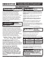 3
3
-
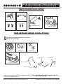 4
4
-
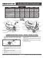 5
5
-
 6
6
-
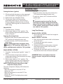 7
7
-
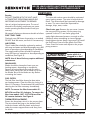 8
8
-
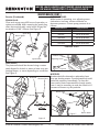 9
9
-
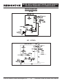 10
10
-
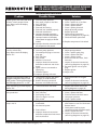 11
11
-
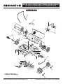 12
12
-
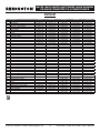 13
13
-
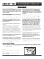 14
14
-
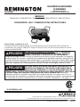 15
15
-
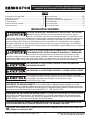 16
16
-
 17
17
-
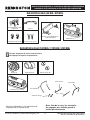 18
18
-
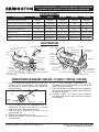 19
19
-
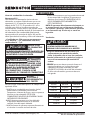 20
20
-
 21
21
-
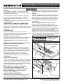 22
22
-
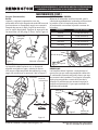 23
23
-
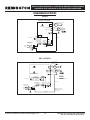 24
24
-
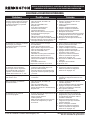 25
25
-
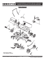 26
26
-
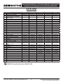 27
27
-
 28
28


Remington REM-140T-KFA-O Manual de usuario
- Tipo
- Manual de usuario
en otros idiomas
- English: Remington REM-140T-KFA-O User manual
Artículos relacionados
Otros documentos
-
 Heat Stream HS-70T-KFA Guía del usuario
-
ProTemp PT-75T-KFA User's Manual & Operating Instructions
-
ProTemp PT-80-OFR Manual de usuario
-
Master MH-80-OFR Manual de usuario
-
Sharper Image Deluxe Foot Heater El manual del propietario
-
-
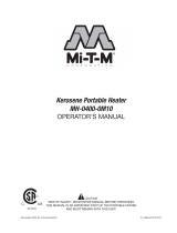 Mi-T-M Kerosene Portable Heaters Manual de usuario
-
Mi-T-M MH-0125-0M10 Manual de usuario
-
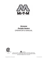 Mi-T-M Kerosene Portable Heaters Manual de usuario
-
 Thermoheat RMC-KFA75TL User's Manual And Operating Instructions


