EcoSmart ECOS 12 Manual de usuario
- Categoría
- Calentadores de agua
- Tipo
- Manual de usuario

USE & CARE MANUAL
MANUAL DE USO Y CUIDADO
Do not destroy this manual. Please read carefully and keep in a safe place for future reference.
No destruya este manual. Por favor, léalo atentamente y guárdelo en un lugar seguro para futuras consultas.
Note: This Use & Care Manual covers EcoSmart® branded tankless electric water heaters.
Nota: Este Manual de Uso y Cuidado cubre los calentadores de agua eléctricos sin tanque de las marcas EcoSmart®.
TANKLESS ELECTRIC WATER HEATERS
CALENTADOR DE AGUA ELÉCTRICO SIN TANQUE
12KW 18KW 27KW
ECOS 12 ECOS 18 ECOS 27

2
When installing or using any high voltage electrical appliance, basic safety precautions should
always be followed. Under no circumstance should you attempt to clean, install, inspect, repair,
disassemble or otherwise service this water heater, without rst shutting off all power to the
unit directly at the circuit breaker box. SERIOUS BODILY INJURY OR DEATH COULD OCCUR
IF YOU IGNORE THIS WARNING.
THIS PRODUCT SHOULD BE INSTALLED BY A QUALIFIED ELECTRICIAN AND A
QUALIFIED PLUMBER IN ACCORDANCE WITH ALL NATIONAL, STATE, PROVINCIAL
AND LOCAL ELECTRICAL & PLUMBING CODES.
PLEASE READ THESE INSTRUCTIONS THOROUGHLY AND COMPLETELY PRIOR TO
INSTALLATION & USE. FAILURE TO DO SO COULD CAUSE PROPERTY DAMAGE,
SERIOUS INJURY, OR DEATH.
This manual should be given to the homeowner after installation and should be retained for
future reference.
Tested and Certied by the Water Quality
Association against NSF/ANSI/CAN 372 for
lead free compliance.
IMPORTANT SAFETY INFORMATION
READ ALL INSTRUCTIONS BEFORE USING
Product Registration is required to obtain warranty service. Incomplete Warranty Registrations will not be
accepted. Product Warranties are void without receipt of Warranty Registration information within 30 days of
receipt and installation of Product
HOW TO REGISTER YOUR PRODUCT
Warranty requires product registration. To register, complete the registration form by
scanning the QR Code. For additional support contact:
EcoSmart 877-474-6473
cETLus (Intertek) certied to UL499
CONTENTS
SIZING GUIDE ........................................................................ 3
SAFETY ................................................................................... 4
BEFORE INSTALLATION ........................................................ 5
SELECTING AN INSTALL LOCATION .................................... 6
MOUNTING YOUR WATER HEATER ..................................... 6
PLUMBING INSTALLATION.................................................... 7
ELECTRICAL REQUIREMENTS .............................................. 8
ELECTRICAL INSTALLATION ................................................. 9
GENERAL OPERATING INSTRUCTIONS ............................... 10
USER INTERFACE ................................................................... 10-11
MAINTENANCE .................................................................... 12-13
TROUBLESHOOTING GUIDE ................................................ 14-15
SPARE PARTS ......................................................................... 15
WARRANTY ........................................................................... 16-17
© 2022 Rheem Manufacturing Company. EcoSmart® trademark is owned by Rheem Manufacturing Company.

3
SIZING GUIDE
Please use the chart below to see how many gallons per minute your tankless water heater can
produce with your incoming water temperature. The gallons per minute is calculated assuming
105°F outlet temperature.
To ensure the optimal temperature output and overall performance of your tankless water heater
you may require a ow regulator. These ow regulators are installed on the outlet connection of
your tankless water heater and limit the maximum volume coming out of your unit to a specied
ow rate to prevent the exit temperature from becoming too cool. To learn more about ow
regulators or nd out how to purchase one for your tankless water heater visit
parts.eemax.com, use the ow regulator part number from the table below.
FLOW REGULATOR – OPTIONAL
INLET WATER TEMPERATURE — F°
37° 42° 47° 52° 57° 62° 67° 72° 77°
kW Region A Region B Region C Region D Region E Region F Region G Region H Region I
12 1.2 1.3 1.4 1.5 1.7 1.9 2.2 2.5 2.9
18 1.8 2.0 2.1 2.3 2.6 2.9 3.2 3.7 4.4
27 2.7 2.9 3.2 3.5 3.8 4.3 4.9 5.6 6.6
Gallons Per Minute To Achieve 105°F Outlet temp
INLET WATER TEMPERATURE
A B C D E F G H I
12 kW IFR 1-2
Silver IFR 1-2
Dark Green IFR 1-2
Purple IFR 1-2
Purple
18 kW IFR 3-4
Purple IFR 3-4
Purple IFR 3-4
Purple IFR 3-4
Red
27 kW IFR 3-4
Purple IFR 3-4
Light Green IFR 3-4
Black IFR 3-4
Black
Steps for Choosing a Flow Regulator
1. Find your model in the chart on the right.
2. Choose the column with the inlet water
temperature closest to your geographical
location.
3. Take the letter matching your zone and model
number and match it with the corresponding
ow regulator on the right.
*Selection based on inlet temperature above and outlet temperature of 105°F
A
B
C
D
E
F
G
H
I
37°FA 42°FB47°FC 52°FD 57°FE
62°F
F67°F
G72°F
H77°F
I
A
B
C
D
E
F
G
H
I
37°FA 42°FB47°FC 52°FD 57°FE
62°F
F67°F
G72°F
H77°F
I
Average Ground Water Temperatures
of the United States*
*Source: US Environmental Protection Agency

4
!DANGER!
WATER TEMPERATURE SAFETY SETTING
Safety and energy conservation are factors to be considered
when selecting the water temperature setting of water heater’s
thermostat. Water temperatures above the 125°F can cause
severe burns or death from scalding. Be sure to read and follow
the warnings outlined on the label pictured below. This label
is also located on the water heater near the thermostat access
panel.
Water temperature over 125 °F
can cause severe burns instantly
or death from scalds.
Children, disabled and elderly are
at highest risk of being scalded.
See instruction manual before set-
ting temperature at water heater.
Feel water before bathing or
showering.
Temperature limiting valves are
available, see manual.
Notice: To protect against injury, you
should install a mixing valve in the water
system. This valve will reduce point of
discharge temperature by mixing cold
and hot water in branch supply lines.
Such valves are available from your local
plumbing supplier.
DANGER: Households with small
children, disabled, or elderly persons may
require a 120°F or lower thermostat setting to
prevent contact with “HOT” water. The tem-
perature of the water in the heater is regulated
by the electronic control on the front of the
water heater. To comply with safety regulations,
the thermostat was set at 120°F/49°C before the
water heater was shipped from the factory.
Temperature Time to Produce a Serious Burn
120 °F More than 5 minutes
125 °F 1 ½ to 2 minutes
130 °F About 30 seconds
135 °F About 10 seconds
140 °F Less than 5 seconds
145 °F Less than 3 seconds
150 °F About 1½ seconds
155 °F About 1 second
The chart shown above may be used as a guide in de-
termining the proper water temperature for your home.
Table courtesy of Shriners Burn Institute
!
SAFETY

5
BEFORE INSTALLATION
PLEASE READ THESE INSTRUCTIONS THOROUGHLY AND COMPLETELY PRIOR TO
INSTALLATION & USE. FAILURE TO FOLLOW INSTRUCTIONS COULD CAUSE PROPERTY
DAMAGE, SERIOUS PERSONAL INJURY, OR DEATH.
By installing this product, you acknowledge the terms of the manufacturer’s warranty. Once the
heater is installed, do not return product to the place of purchase. If you have any questions
regarding the warranty or product return policies, please contact:
Electric drill for
pre-drilling holes
Phillips and Flat head
screwdrivers
Tape measure/ruler
½” dielectric unions - 12 kW
¾” dielectric unions - 18/27 kW
½” shut off valves - 12 kW
¾” shut off valves - 18/27 kW
Adjustable wrench
Pipe cutter
(may be benecial)
Pencil
Level
12 kW 18 kW 27 kW
REQUIRED TOOL LIST:
12 kW 18 kW 27 kW
ELECTRICAL
Power (kW) 12 kW 18 kW 27 kW
Voltage (V) 240V 240V 240V
Total Current (Amps) 50 75 112.5
Required Wire Size
(CU) 75ºC (AWG) 8 8 8
Required minimum breaker size
(per NEC-Intermittent Duty) 1x50 2x40 3x40
TEMPERATURE
Temperature Adjustment Range (F) 60-140 60-140 60-140
PLUMBING
Turn-On Flow Rate (GPM) 0.3 0.3 0.3
Inlet & Outlet Fittings ½” NPT ¾” NPT ¾” NPT
PRODUCT INFORMATION
Product Height (in) 16.25 19 19
Product Width (in) 7.25 9.25 9.25
Product Depth (in) 3.5 4.25 4.25
Product weight (lb) 5 9.3 10.9
PRODUCT SPECIFICATIONS:
Manual Warranty Card
(inside manual)
Inspect all components.
The contents of your box should include one of the following units:
BRAND CALL EMAIL
EcoSmart®877-474-6473 [email protected]

6
SELECTING AN INSTALL LOCATION
MOUNTING YOUR WATER HEATER
This product is designed to be installed indoors only. You may install your unit in an outdoor lo-
cation so long as it is mounted in a suitable enclosure that protects it from rain, splashed water,
direct sunlight, debris, and insects.
DO NOT install this product in a location where it may be subjected to freezing
temperatures. If the water inside your tankless water heater freezes, it can cause
severe and permanent damage that is not covered under your warranty.
DO NOT locate the water heater in a location that is difcult to access.
Make sure that the water heater and hot water outlet pipe are out of reach of children, so they
are unable to tamper with the temperature controls or injure themselves by touching the hot
water outlet pipe. The outlet water pipe can get very hot.
This product does NOT require venting.
Avoid installing your tankless water heater in a location prone to excessive humidity, moisture, or
dust, or in an area where it may be splashed with water or other liquids.
DO NOT install under water pipes or air conditioning lines that might leak or
condense moisture that could then drip onto the heater.
DO NOT install above electrical boxes or junctions.
CAUTION: The water heater should not be located in an area where leakage will result
in damage to the area adjacent to it or to lower oors of the structure. Where such areas
cannot be avoided, it is recommended that a suitable catch pan, adequately drained, be
installed under the water heater.
Your tankless water heater should be secured to the mounting surface with 4 screws (minimum
1-inch long) using the built-in mounting brackets on each side of the heater. Make sure that
the mounting surface is solid and secure and ensure that the unit is level prior to securing the
screws. For ease of installation and servicing, we recommend that this product be installed in an
upright position with the inlet and outlet water connections at the bottom of the unit.
18 i n
15 i n
9. 4 in
6. 9 in
1 .9 in
15 i n
10 .4 in
7. 1 in
5. 1 in
3. 6 in
4 in
0. 9 in
0. 2 in
4-
0. 2 in
4-
18 i n
15 i n
9. 4 in
6. 9 in
1 .9 in
15 i n
10 .4 in
7. 1 in
5. 1 in
3. 6 in
4 in
0. 9 in
0. 2 in
4-
0. 2 in
4-
Required Clearances:
12kW - 7 inches top and
bottom
18kW - 12 inches top only
27kW - 14 inches top only
CAUTION: Combustible
materials should be kept
at least 24 inches away
from your water heater
and the hot water outlet
pipe.
18/27kW
12kW

7
Please follow all plumbing instructions carefully. We recommend that this product be installed by
a licensed and qualied plumber in accordance with all applicable national, state, provincial, and
local plumbing codes.
INSTALLATION INSTRUCTIONS
STEP 1: Make sure the inlet lter screen is present in the inlet tting and the inlet and outlet
pipes are correctly aligned with the heater connections to minimize stress on the heater.
STEP 2: Connect the plumbing to your water heater. The rule of thumb for installing tapered
threaded ttings is nger tight plus ½ to 1 turn with a wrench. Do not tighten more than 2 turns
past nger tight. Use 1 ½ turns of Teon tape going clockwise around the thread, leaving the
rst 2 threads un-covered to avoid contaminating the water ow into the heater.
STEP 3: Fully open the inlet and outlet ball valves. Test with ow and without. Check the system
for water leaks at all plumbing connections. If a leak is present at the NPT threads, slowly tighten
the female NPT tting up to 2 turns past nger tight. If still leaking, remove female NPT to check
for damage or contamination. Replace Teon tape before threading NPT back on.
1. Do not solder any pipes with unit connected to pipes – heat from soldering may
damage the ow sensor. Doing so will void the warranty.
2. This automatic tankless water heater is equipped with both computer-controlled and
electro- mechanical auto resetting thermostat switches for high-limited temperature
protection. Since this product does not use a storage tank, the use of a temperature
pressure relief valve (T&P) is not required for most installations. UL Standard 499
does NOT require that a pressure relief valve be used. However, a T&P valve may be
required to meet installation codes in your area. If one is required, install the pressure
relief valve in accordance with local codes and ensure that it operates correctly and
that air is purged from the valve prior to installing the water heater. When connecting
to Flex or High Temperature CPVC pipe, we recommend that a T&P valve be used
for added safety. Please note: Installations in the Commonwealth of Massachu-
setts and State of Kentucky require a pressure relief valve. Please check your
local installation codes for any special requirements.
3. The maximum operating water pressure is 150 PSI. If the water pressure is higher, a
pressure reducing valve must be installed on the main incoming water supply line
prior to installing the electric tankless water heater.
4. Flexible water heater hoses are recommended to be used with your water heater as
part of the installation. When connecting the inlet water pipe to the unit, make sure
to use a wrench to hold the unit’s connection, and another wrench to tighten, so
that the ow sensor on the unit will not be loosened or damaged. Serious internal
damage to the water heater can occur if the inlet or outlet connections are over
tightened or if solder connections were made.
5. We recommend that a manual shut-off valve (ball valve) is installed on the inlet and
outlet of the water heater so that there is a convenient shut-off point available in the
event that future maintenance or servicing is required. It is extremely important to
ush the lines to eliminate all plumbing paste or residue in the lines caused by any
welding or soldering before connecting pipes to the water heater.
PLUMBING INSTALLATION
PLUMBING REQUIREMENTS: INSTALLATION REQUIREMENTS:
Minimum turn on ow rate 0.3 GPM Use ½” and ¾” NPT ttings for install
Minimum working pressure 30-150 PSI 12kW units have ½” ttings
Optimal operating pressure 35-80 PSI 18kW & 27kW units have ¾” ttings
Boiler drains (may be benecial)
CAUTION: Do not over-tighten plastic ttings.

8
Model Voltage kW Total
Amps Required Wire Size
(CU) 75° C Required minimum breaker
size (per NEC - Intermittent Duty)
12 kW 240 12 50 8 AWG 1x50
18 kW 240 18 75 8 AWG 2x40
27 kW 240 27 112.5 8 AWG 3x40
A ground terminal (or a wire connector marked “G”, “GR”, “Ground”, or “GROUNDING”)
is provided within the enclosure. To reduce the risk of electric shock, connect this terminal or
connector to the grounding terminal of the electric service or supply panel with a continuous
copper wire in accordance with your local electrical code.
12 kW requires 1 double pole
breaker and 1 set of wires
18 kW requires 2 sets of double pole breakers and wires
27 kW requires 3 sets of double pole breakers and wires
WIRING DIAGRAM
ELECTRICAL REQUIREMENTS
L1
(Black) L1
(Black) L1
(Black)
L2
(Red) L2
(Red) L2
(Red)

9
Manufacturer recommends that this product
be installed by a licensed and qualied electri-
cian in accordance with all applicable national,
state, provincial, and local electrical codes. As
with all electrical appliances, under no circum-
stances should you attempt to install, repair
or disassemble this water heater without rst
shutting off all power to the unit directly at the
fuse or breaker box. Make sure to shut off
all breakers. SERIOUS BODILY INJURY OR
DEATH COULD OCCUR IF YOU IGNORE
THIS WARNING.
All wiring (wire gauge) and circuit protection
(breakers) must comply with the U.S. National
Electrical Code (NEC) in the USA, or the
Canadian Electrical Code (CEC) in Canada.
Failure to do so could result in property
damage and/or personal injury, and void
your warranty. Note: The Canadian Electrical
Code generally requires that all supply wires
and corresponding circuit protection used
for domestic hot water heating and hydronic
heating applications be sized to a minimum
of 125% of the maximum current rating of the
heater (see model specications below for
details).
Before installing this product, ensure that the
home has sufcient electrical power available
to handle the maximum amperage load of the
applicable model.
ELECTRICAL INSTALLATION
Please see electrical specications by model and wiring diagram on the next page for additional
electrical information.
Each set of wires must be connected to its own individual double pole breaker.
STEP 1: Take each wire pair and connect them
to one breaker (see wiring diagram). Make
sure that each breaker is connected with one
black wire and one red wire
STEP 2: Using a suitable wire gauge that
meets all applicable electrical codes for the
size of the breakers used, run the correct sets
of wire from the home’s main breaker panel to
the tankless water heater.
STEP 3: A separate ground conductor for
each incoming circuit is required.
STEP 4: DOUBLE CHECK the electrical
connections to make sure they are correct and
that all wire connections are tight and secure.
Also conrm that the correct breaker size and
wire gauge has been used and conrm that
the unit has been connected to a ground in
accordance with applicable codes.
STEP 5: Conrm that all the air has been
purged from the water lines prior to turning
on power to the unit. Refer to STEP 2 in the
plumbing installation section.
INSTALLATION INSTRUCTIONS
CAUTION: Ensure that you have made the correct connections. You must follow the wire
connection as shown to ensure proper operation of the unit. If you mix up one set of wires
with another, the unit will not operate correctly even though it turns on and otherwise
appears to function properly.
The water heater is now installed and ready to use! Follow the General Operating
Instructions to complete the setup. We highly recommend that this is done with the homeowner
present.
IMPORTANT NOTES:
Model 12 kW requires 1 set of wire and ground (see wiring diagram)
Model 18 kW requires 2 sets of wire and ground (see wiring diagram)
Model 27 kW require 3 sets of wire and ground (see wiring diagram)

10
CAUTION: Removing the cover to change the temperature set point exposes
electrical shock and burn hazards, which can cause INJURY or DEATH.
Adjustment should only be done by a licensed plumber or electrician.
DANGER: Hotter water increases the potential for Hot Water SCALDS.
*CAUTION* BEFORE SWITCHING THE ELECTRICAL BREAKER “ON”, VERIFY
THE INLET AND OUTLET BALL VALVES ARE FULLY OPEN AND WATER IS
FLOWING THROUGH THE HOT WATER FAUCET FOR A MINUTE OR TWO
UNTIL THE FLOW IS CONTINUOUS AND FREE FROM AIR POCKETS. DO
NOT SWITCH THE BREAKER “ON” IF THERE IS A POSSIBILITY THE WATER
IN THE HEATER IS FROZEN.
COMMISSION HEATER
Upon power on, the software revision screen is displayed,
then the power selection screen (12, 18, 27 kW).
The next screen represents the SAFE title, then “-1.5”G is
displayed. This is a counter that represents the volume of
water in gallons remaining to pass through the unit before
the unit is considered commissioned.
At this point, water needs to be turned on.
After the counter reaches “0.0”, the temperature setpoint
screen is displayed. At this point, the unit is commissioned
and will heat water upon demand.
Temperature adjustable range: 60 °F – 140 °F
(Continued on next page)
GENERAL OPERATING INSTRUCTIONS
USER INTERFACE
SELECT BUTTON
INCREASE
TEMPERATURE
BUTTON
DECREASE
TEMPERATURE
BUTTON
Operating your new tankless water heater is similar to using any
traditional water heating system. However, it is very important that you
carefully read all of the setup procedures and operating instructions and
tips to ensure the maximum performance and energy savings from your
new water heater. We recommend that all members of the household
read these General Operating Instructions.
How your new water heater works: Your tankless water heater does
not store hot water like a traditional tank-type water heater. It contains
high powered heating elements that are capable of heating water
on-demand. As soon as you turn on a hot water faucet, a sophisticated
ow sensor recognizes that you have turned on the water. This sensor
measures ow rate while another sensor measures the incoming water
temperature. This information is transmitted continually to the computer
logic controls which decide how much power to send to the heating
elements to heat the water to your desired temperature. Once the water
faucet is turned off your water heater will turn off as well.
OUTLET INLET

11
— BUTTON + BUTTON
— BUTTON + BUTTON
— BUTTON + BUTTON
— BUTTON + BUTTON
— BUTTON + BUTTON
— BUTTON + BUTTON
— BUTTON + BUTTON
CHANGING SETPOINT TEMPERATURE
To INCREASE temperature, tap the “ ” button repeatedly, or hold the “ ” down
to INCREASE the temperature quickly.
To DECREASE temperature, tap the “ ” button repeatedly, or hold the “ ” down
to DECREASE the temperature quickly.
Hold “ ” pressed for 3 seconds to access the Settings menu.
To return to home screen press “ ” and hold for 3 seconds (will automatically return to home
screen after 60 seconds of inactivity).
USER INTERFACE CONT.
INITIAL STARTUP SCREEN FLOW
Software revision Flow rate in GPM
or LPM
Water temperature
leaving unit
Water temperature
entering unit
Power factor/demand
(F) Or (C)
Rated power displayed,
for 18kW unit. Could
be P012 or P027 based
on unit
Software revision
Unit beyond heating
capacity and ≥ 5°F
below set point
Software version
Rated power for 18kW
unit. Could be P012 or
P027 based on unit
Safestart™ initiated
Safestart™ ow volume
countdown to 0
Home screen: Default
temperature setting
Hold 3 seconds
Hold 3 seconds
Use the + or — to set unit
Power Selector 1 or 2
Hold 3 seconds
Use the + or — to set Power Method
— BUTTON + BUTTON

12
MAINTENANCE
FLUSHING THE WATER HEATER
Flushing the heat exchanger is a complicated procedure that should only be performed by a
qualied service technician.
NOTE:
Improper maintenance WILL VOID water heater warranty.
1. Disconnect electrical power to the water heater.
2. Close the shutoff valves on both hot water outlet and cold water inlet lines (V1 and V2).
See Figure 1.
3. Connect one hose (D1, Figure 1) to the valve (V3) and place the free end in a bucket.
Connect one of the hoses (D3) to the circulation pump outlet and the cold water inlet
line to valve V4. Connect the other hose (D2) to the circulation pump inlet and place the
free end in the bucket.
To ensure maximum performance of your water heater and to reduce the risk of a water
leak, we recommend the following maintenance:
Inspect the connections on the inlet and outlet of the water heater at least on an annual basis
for any signs of damage or failure. Any signs of damage, cracks, leakage or weakness should be
addressed. Take care not to over tighten the connections. Serious internal damage to your water
heater can occur if you over tighten the water heater connections at the unit.
IMPORTANT NOTES:
As with all electrical appliances, under no circumstances should you attempt to install, repair or disas-
semble this water heater without rst shutting off all power to the unit directly at the fuse or breaker box.
SERIOUS BODILY INJURY OR DEATH COULD OCCUR IF YOU IGNORE THIS WARNING.
When any maintenance is performed on the water heater or the home’s plumbing system that may
introduce air into the plumbing pipes, it is important to turn the power off to the water heater and purge
the air out of the lines before allowing the unit to power up. FAILURE TO DO SO COULD CAUSE PER-
MANENT DAMAGE TO THE HEATING ELEMENT AND VOID YOUR WARRANTY.
If you have a water supply with a high level of mineralization (hard water), you should increase the
frequency of your maintenance.
V1
V2
V3 V4
D1
D2
D3
Figure 1 – Flushing the Water Heater

13
4. Pour tankless water heater cleaning solution into the bucket. Ensure the cleaning
solution is approved for potable water systems. Place the drain hose (D1) and hose D2
to the pump inlet in the cleaning solution.
5. Open service valves (V3 and V4) on the hot water outlet and cold water inlet lines.
6. Turn on the circulation pump. Operate the pump and allow the cleaning solution to
circulate through the water heater for at least 1 hour at a rate of 4 gallons per minute.
This will remove any possible harmful scale deposits.
7. Rinse the cleaning solution from the combination water heater as follows:
a. Remove the free end of drain hose D1 from the bucket.
b. Close service valve V4 and open shutoff valve V2.
c. Do not open shutoff valve V1.
d. Allow water to ow through the water heater for 5 minutes.
e. Close shutoff valve V2.
8. Disconnect all hoses.
9. Remove the cold water inlet lter from the water heater and clean out any residues.
10. Reinsert the lter and ensure the lter cap is securely tightened.
11. Open a hot water faucet. Run the water heater continuously for ve minutes to ensure all
cleaning solution is purged from the system. Check for leaks and ensure the water heater
is operating properly.
12. Connect electrical power to the water heater.

14
PROBLEM
Water heater is not heating
at all (water is owing but
the unit is not heating - the
outgoing water temperature
is the same as the cold water
supply) - the digital display
does NOT light up.
Water heater is not heating
at all (water is owing but
the unit is not heating - the
outgoing water temperature
is the same as the cold water
supply) The digital display
DOES light up.
Water heater is
heating, but the water tem-
perature is not hot enough.
The water temperature
at the faucet is less than the
temperature setting
of my water heater
POSSIBLE CAUSE
No power or incor-
rect wiring.
Flow rate is too low
/ water pressure is
too low.
Internal part failure.
User temperature
setting too low.
Flow rate is too high
Crossed wires.
Voltage less than
240 volts.
Mixing too much
cold water.
Voltage less than
208 volts.
Anti-Scald pressure/
balancing valve or
tempering valve.
Thermal loss due to
long pipe run
SOLUTIONS
Make sure the breakers at main electrical panel are ON. You may have a
faulty breaker or unit may be wired incorrectly.
Your water heater has an activation ow rate of approximately 0.3 GPM.
If your water ow rate is less than this level, your unit will not activate.
Increase the ow rate.
Please call us for technical assistance.
Turn up the temperature setting on the unit.
Depending on your incoming water temperature and the power output of
your model, your water ow rate may exceed the physical heating capacity
of your water heater. Reduce the ow rate by installing an EcoSmart Flow
Regulator. Use the chart in section 6 to nd out which ow regulator
works best for your particular model.
If it’s a new installation, have your electrician double check the wiring. Is
possible that the wiring is incorrect.
The heating elements on your water heater are design for 240 volts. When
used with a lower voltage, they produce less heating power. You may
need to upgrade to a larger model.
You do not need to mix as much cold water with your tankless water
heater compared to when you use a conventional water heater. You may
also have an anti-scald feature on your faucet that is mixing cold water.
These types of faucets can usually be adjusted to reduce the amount of
cold water mixed.
The computer chips in your tankless water heater are programmed with
the expectation that your incoming line voltage is 240 volts. If you have
less than 240 volts, it may affect the reading on your water heater’s digital
display and cause it to read slightly higher than the actual output tempera-
ture. To compensate for this, increase the setting on your water heater if
you need / want hotter water.
Your faucet may have an anti-scald feature or a tempering valve that automat-
ically mixes cold water even when you turn your control lever or handle to
full hot. These devices are usually adjustable so you can turn off the cold mix
completely. You can compensate for this by increasing the setting on your
water heater if you need/want hotter water.
As the hot water from the heater runs through the hot water delivery system
to your faucet, some heat will be lost especially if it has long distance to
travel or the pipes are cold. This is normal. You can compensate for this by
increasing the setting on your water heater if you need/want hotter water.
The following table represents some of the most common technical support questions.
TROUBLESHOOTING GUIDE
Please call or email our customer experience and technical support team for any help you may need.
BRAND CALL EMAIL
EcoSmart®877-474-6473 [email protected]

15
DISPLAYED
NOTIFICATION
MESSAGE DESCRIPTION CAUSE UNIT BEHAVIOR
A70 Outlet Temperature
too high
Outlet temperature is >
(setpoint + 20°F)
Unit turns off power to the heating element until outlet
temperature is less than setpoint. This notication is
disabled if c05 or b10 notications are present
A74 Intel or outlet tempera-
ture below freezing
Inlet or outlet temperature
< 35°F
Unit turns off power to the heating element until both
inlet and outlet temperature > 35°F
b00 Inlet thermistor
disconnected Inlet temperature < 0°F Unit keeps heating with assumed 65°F inlet temperature
b10 Both thermistors
disconnected
Inlet and outlet
temperature < 0°F
Unit keeps heating with assumed 65°F inlet
temperature, ow and latest self-calibration
c05 Outlet thermistor
Disconnected Outlet temperature < 0°FUnit keeps heating with assumed 65°F inlet
temperature, ow and latest self-calibration
d85 Flow too high, inlet
temperature too low
Power demand > 100%
or unit capacity
Unit continues to operate, however set temperature
will not be reached
ITEM NO. PART NAME (TOP LEVEL) EEMAX PART NUMBER
1Inlet manifold sub-assembly 12kw EX78033-00
2Outlet manifold sub-assembly for 12kW EX78034-00
3Inlet manifold w/ sensors & owmeter sub-assembly for 18/27kW EX78033-01
4Outlet manifold w/ sensors sub-assembly for 18/27kW EX78034-01
5Gaskets pack for 12kW EX78035-00
6Gaskets pack for 18/27 kW EX78035-01
7Heat Element replacement kit for 12kW EX78038-00
8Heat Element replacement kit for 18kW EX78038-01
9Heat Element replacement kit for 27kW EX78038-02
10 Thermistors kit for 12kW EX78039-00
11 Thermistors kit for 18/27kW EX78039-01
12 Flowmeter & sensor replacement kit for 12kW EX78040-00
13 Flowmeter & sensor replacement kit for 18/27kW EX78040-01
14 Kit for 12kW EX78041-00
15 Kit for 18kW EX78041-01
16 Kit for 27kW EX78041-02
17 Triac Kit with yellow plug wiring for 12kW EX08001-03A
18 Triac Kit with red plug wiring for 12kW EX08001-03B
19 Triac kit with yellow plug & wiring for 18kW EX08001-04A
20 Triac kit with red plug & wiring for 18kW EX08001-04B
21 Triac kit with yellow plug & wiring for 27kW EX08001-05A
22 Triac kit with red plug & wiring for 27kW EX08001-05B
23 Triac kit with blue plug & wiring for 27kW EX08001-05C
24 Spare PCBA for 12kW EX09100-350
25 Spare PCBA for 18kW EX09100-356
26 Spare PCBA for 27kW EX09100-357
27 Transformer for 12 kW EX08209-03
28 Transformer for 18/27kW EX08209-04
TROUBLE SHOOTING GUIDE CONT.
SPARE PARTS
ERROR CODES

16
Subject to the terms and conditions set forth in
this limited warranty, each Tankless Water Heater is
warranted to the original owner (“Owner”) against
(i) mechanical or electrical failure of any component
solely due to defects in materials or Manufacturer’s
workmanship for a period of one year from the
date of original purchase and (ii) leaks solely
due to defects in materials or Manufacturer’s
workmanship for the later of (x) ve years from the
date of original purchase or (y) the date of Owner’s
occupancy of a new dwelling in which the Tankless
Water Heater is installed. However, if Owner
cannot document the original date of purchase
with the original sales receipt, then the limited
warranty period begins on the date the Tankless
Water Heater was manufactured. As Owner’s
sole and exclusive remedy, Manufacturer shall,
at Manufacturer’s sole election, either repair or
replace the Tankless Water Heater or the defective
portion of such product. Manufacturer is not liable
for any costs incurred by Owner, including, without
limitation, the cost of any labor. Manufacturer’s
maximum liability is limited to the value of the
water heater. This limited warranty shall be
governed by the laws of the United States.
THE LIMITED WARRANTY SHALL BE
THE EXCLUSIVE WARRANTY MADE BY
MANUFACTURER AND IS MADE IN LIEU
OF ALL OTHER WARRANTIES, STATUTORY,
EXPRESSED OR IMPLIED (WHETHER WRITTEN
OR ORAL), INCLUDING, BUT NOT LIMITED
TO, WARRANTIES OR MERCHANTABILITIES
AND FITNESS FOR A PARTICULAR PURPOSE.
MANUFACTURER EXPRESSLY DISCLAIMS THE
IMPLIED WARRANTIES OF MERCHANTABILITY
AND FITNESS FOR A PARTICULAR PURPOSE,
AS WELL AS ALL OTHER EXPRESS OR IMPLIED
WARRANTIES NOT EXPRESSLY PROVIDED
HEREIN. OWNER’S SOLE AND EXCLUSIVE
REMEDY IS PRODUCT REPAIR OR REPLACED,
AS PROVIDED IN THIS LIMITED WARRANTY,
AND ALL OTHER CLAIMS FOR DAMAGES ARE
EXPRESSLY EXCLUDED.
THE REMEDIES SET FORTH IN THIS LIMITED
WARRANTY ARE THE ONLY REMEDIES
AVAILABLE TO OWNER OR ANY PERSON
FOR BREACH OF ANY COVENANT,
DUTY OR OBLIGATION ON THE PART OF
MANUFACTURER. MANUFACTURER IS NOT
LIABLE TO OWNER OR ANY THIRD PARTY FOR
ANY LOSS, PERSONAL INJURY OR PROPERTY
DAMAGE, DIRECTLY OR INDIRECTLY, ARISING
FROM THE TANKLESS WATER HEATER. UNDER
NO CIRCUMSTANCES IS MANUFACTURER
LIABLE TO OWNER OR ANY THIRD PARTY
FOR INCIDENTAL, CONSEQUENTIAL, SPECIAL,
CONTINGENT, OR PUNITIVE DAMAGES OF ANY
DESCRIPTION, WHETHER ANY SUCH CLAIM
BE BASED UPON WARRANTY, CONTRACT,
NEGLIGENCE, STRICT LIABILITY, OR OTHER
TORT, OR OTHERWISE.
Some states do not allow the exclusion or limitation
of incidental or consequential damages, so the
above limitation or exclusion may not apply to
Owner. In such cases, the warranty shall be limited
to one year from the original date of purchase or
date of manufacture, as provided in this limited
warranty, or the shortest period allowed by law.
This warranty gives Owner specic legal rights and
Owner may also have other rights which may vary
from state to state.
EXCLUSIONS OF COVERAGE FROM THIS
LIMITED WARRANTY
1) Manufacturer is not liable for any water
damage or other damages arising, directly
or indirectly, from any defect in the Tankless
Water Heater component part(s) or from its
use.
2) Manufacturer is not liable under this limited
warranty or otherwise if:
(a) | The water heater or any of its component
parts have been subject to misuse, abuse,
alteration, neglect or accident; or
LIMITED WARRANTY INFORMATION -
TANKLESS ELECTRIC WATER HEATERS
For EcoSmart® Tankless Electric Water Heaters

17
(b) The rating plate(s) or serial number(s) are
altered or removed; or
(c) The water heater has not been installed
in accordance with the applicable local
plumbing and/or building code(s) and/or
regulation(s); or
(d) The water heater has not been installed
or maintained in accordance with
Manufacturer’s printed instructions,
or installed with improper orientation,
improper fastening, improper use of pipe
dope/ plumbers putty or with the use of
any non-Manufacturer-approved sealant;
or
(e) The water heater has not been
continuously supplied with potable water
or the water’s inlet temperature is above
Manufacturer’s recommended maximum
temperature; or
(f) The water heater experiences any water
pressure or ow interruptions, normal inlet
water pressure is outside of the published
specication for the heater; is exposed to
any condition that causes the heater to
turn on before the air is purged from the
heater, also known as a dry re; or
(g) The water heater has been exposed
to conditions resulting from oods,
earthquakes, winds, re, freezing,
lightning, or circumstances beyond the
Manufacturer’s control; or
(h) The water heater has been removed from
its original installation location; or
(i) The water heater has been used for other
than the intended purpose.
3) Owner, and not Manufacturer or its agent/
representative, is liable for and shall pay for
all eld charges for labor or other expenses
incurred in the removal and/or repair of the
water heater or any expense incurred by
Owner in order to repair the water heater.
Subject to the terms and conditions set forth
in this limited warranty, if the Tankless Water
Heater fails or leaks because of defects in
materials or Manufacturer’s workmanship during
the applicable warranty period set forth above,
Owner should contact Manufacturer for a
Returned Merchandise Authorization (RMA). No
returns will be accepted by Manufacturer without
an RMA number and Manufacturer assumes
no responsibility for a water heater returned
without an RMA number. Water heaters should
be wrapped and packaged securely to avoid
shipping damage. All shipments of parts from the
Manufacturer to the Owner to replace defective
components shall be made via normal ground
transportation. If expedited shipment is required,
it will be provided at Owner’s additional cost.
Manufacturer’s National Service Department | 400 Captain Neville Dr. Waterbury, CT 06705
EcoSmart 877-474-6473

18
Cuando se instala o usa un artefacto eléctrico de alto voltaje, siempre se deben tener en cuenta
precauciones de seguridad básicas. Bajo ninguna circunstancia debe intentar limpiar, instalar,
inspeccionar, reparar, desmontar o realizar cualquier otro tipo de mantenimiento de este
calentador de agua, sin cortar primero todo el suministro eléctrico de la unidad directamente
en la caja del disyuntor. SI SE IGNORA ESTA ADVERTENCIA PUEDEN PRODUCIRSE
LESIONES CORPORALES GRAVES O LA MUERTE.
ESTE PRODUCTO DEBE SER INSTALADO POR UN ELECTRICISTA Y UN PLOMERO
CALIFICADOS DE ACUERDO CON TODOS LOS CÓDIGOS ELÉCTRICOS
Y DE FONTANERÍA NACIONALES, ESTATALES, PROVINCIALES Y LOCALES.
LEA ESTAS INSTRUCCIONES METICULOSAMENTE Y EN SU TOTALIDAD ANTES DE
LA INSTALACIÓN Y EL USO. DE NO HACERLO, SE PODRÍAN PRODUCIR DAÑOS
MATERIALES, LESIONES GRAVES O LA MUERTE.
Este manual se debe entregar al propietario después de la instalación y se debe conservar para
futuras consultas.
Probado y certicado por Water Quality Association
según la norma NSF/ANSI/CAN 372 para el
cumplimiento de la ausencia de plomo.
INFORMACIÓN IMPORTANTE DE SEGURIDAD
LEA TODAS LAS INSTRUCCIONES ANTES DE USAR
El registro del producto es necesario para obtener el servicio de garantía. No se aceptarán registros de
garantía incompletos. Las garantías de los productos son nulas si no se recibe la información de registro de
la garantía en los 30 días siguientes a la recepción e instalación del producto
CÓMO REGISTRAR SU PRODUCTO
La garantía requiere el registro del producto. Para inscribirse, complete el formulario de
inscripción escaneando el código QR. Para soporte adicional contacte:
EcoSmart 877-474-6473
cETLus (Intertek) con
certicación UL499
CONTENIDO
GUÍA DE TAMAÑOS .............................................................. 19
SEGURIDAD ........................................................................... 20
ANTES DE LA INSTALACIÓN ................................................ 21
SELECCIÓN DEL LUGAR PARA LA INSTALACIÓN ................ 22
MONTAJE DEL CALENTADOR DE AGUA ............................ 22
INSTALACIÓN DE PLOMERÍA .............................................. 23
REQUISITOS ELÉCTRICOS ..................................................... 24
INSTALACIÓN ELÉCTRICA .................................................... 25
INSTRUCCIONES GENERALES DE FUNCIONAMIENTO ...... 26
INTERFAZ DEL USUARIO ....................................................... 26-27
MANTENIMIENTO ................................................................ 28-29
GUÍA PARA LA RESOLUCIÓN DE PROBLEMAS .................... 30-31
PIEZAS DE REPUESTO .......................................................... 31
GARANTÍA ............................................................................ 32-33
© 2022 Rheem Manufacturing Company. Las marcas comerciales EcoSmart® es propiedad de Rheem Manufacturing Company.

19
GUÍA DE TAMAÑOS
Por favor, utilice la siguiente tabla para ver cuántos litros por minuto puede producir su
calentador de agua sin tanque con la temperatura del agua entrante. Los litros por minuto se
calculan suponiendo una temperatura de salida de 40°C.
Para garantizar la salida de temperatura óptima y el rendimiento general de su calentador de agua sin
tanque puede necesitar un regulador de caudal. Estos reguladores de caudal se instalan en la conexión
de salida de su calentador de agua sin tanque y limitan el volumen máximo que sale de su unidad
a una velocidad de caudal determinada para evitar que la temperatura de salida sea demasiado
fría. Para obtener más información sobre los reguladores de caudal o saber cómo adquirir uno
para su calentador de agua sin tanque, visite parts.eemax.com, utilice el número de pieza del
regulador de caudal de la tabla siguiente.
REGULADOR DE CAUDAL - OPCIONAL
A B C D E F G H I
12kW IFR 1-2
Plateado IFR 1-2
Verde Oscuro IFR 1-2
Morado IFR 1-2
Morado
18kW IFR 3-4
Morado IFR 3-4
Morado IFR 3-4
Morado IFR 3-4
Rojo
27kW IFR 3-4
Morado IFR 3-4
Verde Claro IFR 3-4
Negro IFR 3-4
Negro
Pasos para elegir un regulador de caudal
1. Encuentre su modelo en la tabla de la derecha.
2. Elija la columna con la temperatura del agua de
entrada más cercana a su ubicación geográca.
3. Tome la letra que coincida con su zona y número
de modelo y únala con el correspondiente regu-
lador de caudal a la derecha
TEMPERATURA DEL AGUA DE ENTRADA
*Selección basada en la temperatura de entrada de arriba y la temperatura de salida de 40 °C
A
B
C
D
E
F
G
H
I
37°FA 42°FB47°FC 52°FD 57°FE
62°F
F67°F
G72°F
H77°F
I
A
B
C
D
E
F
G
H
I
37°F
A
42°F
B
47°F
C
52°F
D
57°F
E
62°F
F
67°F
G
72°F
H
77°F
3°C 6°C 8°C 11°C 14°C
17°C 19°C 22°C 25°CI
Temperaturas medias de las aguas subterráneas
de Estados Unidos*
*Fuente: Agencia de Protección Ambiental de Estados Unidos
TEMPERATURA DEL AGUA DE ENTRADA — C°
3° 6° 8° 11° 14° 17° 19° 22° 25°
kW Región A Región B Región C Región D Región E Región F Región G Región H Región I
12 4.5 4.9 5.3 5.7 6.4 7.2 8.3 9.5 11.0
18 6.8 7.6 8.0 8.7 9.8 11.0 12.1 14.0 16.7
27 10.2 11.0 12.1 13.2 14.4 16.3 18.5 21.2 22.7
Litros por minuto para lograr una temperatura de salida de 40°C
cETLus (Intertek) con
certicación UL499

20
¡PELIGRO!
AJUSTE DE SEGURIDAD DE LA TEMPERATURA DEL AGUA
La seguridad y el ahorro de energía son factores a tener en
cuenta a la hora de seleccionar el ajuste de la temperatura del
agua del termostato del calentador de agua. La temperatura
del agua por encima de 52 °C puede causar quemaduras graves
o la muerte por quemaduras. Asegúrese de leer y observar las
advertencias indicadas en la etiqueta que se ve en la imagen de
abajo. Esta etiqueta también se encuentra en el calentador de
agua, cerca del panel de acceso al termostato.
La temperatura del agua por encima
de 52 °C puede causar quemaduras
graves al instante o la muerte por
quemaduras.
Los niños, las personas con
discapacidades y los ancianos tienen
alto riesgo de sufrir quemaduras.
Consulte el manual de instrucciones
antes de ajustar la temperatura en el
calentador de agua.
Toque el agua antes de bañarse o
ducharse.
Existen válvulas limitadoras de
temperatura, vea el manual.
Aviso: Para evitar lesiones, debe instalar
una válvula mezcladora en el sistema de
agua. Esta válvula reducirá la temperatura
del punto de descarga mezclando el agua
fría y caliente en las líneas de suministro
de los ramales. Este tipo de válvulas están
disponibles en su proveedor local de
plomería.
PELIGRO: Los hogares con niños
pequeños, discapacitados o personas mayores
pueden requerir un ajuste de termostato de
49 °C o inferior para evitar el contacto con el
agua "CALIENTE". La temperatura del agua
en el calentador se regula mediante el control
electrónico situado en la parte delantera del
calentador de agua. Para cumplir con las normas
de seguridad, el termostato fue ajustado a
120 °F/49 °C antes de que el calentador de agua
fuera enviado desde la fábrica.
Temperatura Hora de producir una
quemadura grave
49 °C Más de 5 minutos
52 °C 1 ½ a 2 minutos
54 °C Alrededor de 30 segundos
57 °C Alrededor de 10 segundos
60 °C Menos de 5 segundos
63 °C Menos de 3 segundos
65 °C Alrededor de 1½ segundos
68 °C Alrededor de 1 segundo
El cuadro que aparece arriba se puede usar como guía
para determinar la temperatura del agua adecuada
para su hogar.
Tabla cortesía de Shriners Burn Institute
SEGURIDAD

21
ANTES DE LA INSTALACIÓN
LEA ESTAS INSTRUCCIONES METICULOSAMENTE Y EN SU TOTALIDAD ANTES DE
LA INSTALACIÓN Y EL USO. SI NO SE RESPETAN LAS INSTRUCCIONES SE PODRÍAN
PRODUCIR DAÑOS MATERIALES, LESIONES PERSONALES GRAVES O LA MUERTE.
Al instalar este producto usted reconoce los términos de la garantía del fabricante. Después
de instalado el calentador no devuelva el producto al lugar de compra. Si tiene alguna
pregunta sobre la garantía o las políticas de devolución de productos, póngase en contacto
c:Inspeccione todos los componentes.
El contenido de la caja debe incluir una de las siguientes unidades:
Taladro eléctrico para
preperforar agujeros
Destornilladores de cabeza
plana y de estrella
Cinta métrica/regla
Uniones dieléctricas de ½"- 12 kW
Uniones dieléctricas de ¾”- 18/27 kW
Válvulas de cierre de ½” - 12 kW
Válvulas de cierre de ¾" - 18/27 kW
Llave ajustable
Cortatubos
(puede ser benecioso)
Lápiz
Nivel
12kW 18kW 27kW
LISTA DE HERRAMIENTAS
NECESARIAS:
12kW 18kW 27kW
ELECTRICIDAD
Potencia (kW) 12kW 18kW 27kW
Voltaje (V) 240V 240V 240V
Corriente total (amperios) 50 75 112.5
Tamaño de cable requerido
(CU) 75ºC (AWG) 8 8 8
Tamaño mínimo requerido del interruptor
(según NEC-servicio intermitente) 1x50 2x40 3x40
TEMPERATURA
Rango de ajuste de la temperatura (F) 60-140 60-140 60-140
PLOMERÍA
Velocidad de caudal de encendido (LPM) 1.14 1.14 1.14
Accesorios de entrada y salida ½" NPT ¾" NPT ¾" NPT
INFORMACIÓN SOBRE EL PRODUCTO
Altura del producto (cm) 41 48 48
Ancho del producto (cm) 18 23 23
Profundidad del producto (cm) 9 11 11
Peso del producto (kg) 2.27 4.2 5
ESPECIFICACIONES DEL PRODUCTO:
Manual Tarjeta de garantía
(dentro del manual)
MARCA LLAMAR EMAIL
EcoSmart®877-474-6473 [email protected]

22
SELECCIÓN DEL LUGAR PARA LA INSTALACIÓN
MONTAJE DEL CALENTADOR DE AGUA
Este producto únicamente se puede instalar en interiores. Puede instalar su unidad en un lugar
exterior siempre que esté montada en un cerramiento adecuado que la proteja de la lluvia, las
salpicaduras de agua, la luz solar directa, los residuos y los insectos.
NO instale este producto en un lugar donde pueda estar sujeto a temperaturas de congelación.
Si el agua dentro de su calentador de agua sin tanque se congela, puede causar un daño severo y
permanente que no está cubierto por su garantía.
NO coloque el calentador de agua en un lugar de difícil acceso.
Asegúrese de que el calentador de agua y el tubo de salida de agua caliente están fuera del
alcance de los niños, para que no puedan manipular los controles de temperatura o hacerse daño
tocando el tubo de salida de agua caliente. La tubería de salida de agua puede calentarse mucho.
Este producto NO requiere ventilación.
Evite instalar su calentador de agua sin tanque en un lugar propenso a la humedad excesiva, la
humedad o el polvo, o en un área donde pueda ser salpicado con agua u otros líquidos.
NO lo instale debajo de tuberías de agua o de aire acondicionado que puedan tener fugas o
condensar humedad que luego podría gotear sobre el calentador.
NO lo instale encima de cajas o empalmes eléctricos.
PRECAUCIÓN: El calentador de agua no debe situarse en una zona en la que las fugas
provoquen daños en la zona adyacente o en los pisos inferiores de la estructura. Cuando
no se pueda evitar este tipo de zonas, se recomienda instalar una bandeja de goteo
adecuada, con un drenaje apropiado, debajo del calentador de agua.
Su calentador de agua sin tanque debe ser asegurado a la supercie de montaje con 4 tornillos
(mínimo de 1 pulgada de largo) usando los soportes de montaje incorporados en cada lado
del calentador. Asegúrese de que la supercie de montaje sea sólida y rme y que la unidad
quede nivelada antes de sujetar los tornillos. Para facilitar la instalación y el mantenimiento,
recomendamos que este producto se instale en posición vertical con las conexiones de entrada
y salida de agua en la parte inferior de la unidad.
457 mm
381 mm
381 mm
264 mm
48 mm
4-
4-
175 mm
238 mm
129 mm23 mm
180 mm
5 mm
5 mm
101 mm
91 mm
457 mm
381 mm
381 mm
264 mm
48 mm
4-
4-
175 mm
238 mm
129 mm23 mm
180 mm
5 mm
5 mm
101 mm
91 mm
Distancias requeridas:
12kW - 7 pulgadas en la
parte superior e
inferior
18kW - 12 pulgadas solo
en la parte superior
27kW - 14 pulgadas solo
en la parte superior
PRECAUCIÓN: Los
materiales combustibles
deben mantenerse al menos
a 24 pulgadas de distancia
de su calentador de agua
y de la tubería de salida de
agua caliente.
18/27kW
12kW

23
Por favor, siga todas las instrucciones de plomería con atención. Recomendamos que este producto
sea instalado por un plomero autorizado y calicado de acuerdo con todos los códigos de plomería
nacionales, estatales, provinciales y locales aplicables.
INSTRUCCIONES DE INSTALACIÓN
PASO 1: Asegúrese de que la malla del ltro de entrada esté presente en el accesorio de entrada y que
los tubos de entrada y salida estén correctamente alineados con las conexiones del calentador para
minimizar la tensión en el calentador.
PASO 2: Conecte las tuberías a su calentador de agua. La regla general para la instalación de accesorios
roscados cónicos es apretarlos con los dedos más ½ a 1 vuelta con una llave. No apriete más de 2 vueltas
más allá del ajuste con los dedos. Utilice 1 ½ vueltas de cinta de teón en el sentido de las agujas del reloj
alrededor de la rosca, dejando las 2 primeras roscas sin cubrir para evitar contaminar el caudal de agua
hacia el calentador.
PASO 3: Abra completamente las válvulas esféricas de entrada y salida. Pruebe con caudal y sin caudal.
Compruebe que no haya fugas de agua en todas las conexiones de plomería. Si hay una fuga en las
roscas NPT, apriete lentamente el accesorio NPT hembra hasta 2 vueltas más allá del ajuste con los
dedos. Si sigue habiendo fugas, retire el NPT hembra para comprobar si hay daños o contaminación.
Vuelva a colocar la cinta de teón antes de enroscar el NPT.
1. No suelde ningún tubo con la unidad conectada a las tuberías, el calor de la soldadura puede
dañar el sensor de caudal. Si lo hace, se anulará la garantía.
2. Este calentador de agua automático sin tanque está equipado con interruptores de
termostato controlados por ordenador y electromecánicos de restablecimiento automático
para la protección de la temperatura de alto límite. Como este producto no usa un tanque
de almacenamiento en la mayoría de las instalaciones no se necesita una válvula de alivio
de presión y temperatura (T&P). La norma UL 499 NO exige el uso de una válvula de alivio
de presión. Sin embargo, tal vez sea necesario instalar una válvula T&P para cumplir con los
códigos de su área. Si es así, instale la válvula de alivio de presión de acuerdo con los códigos
locales y asegúrese de que funcione correctamente y que el aire se purgue de la válvula antes
de instalar el calentador de agua. Cuando se conecte a una tubería de CPVC exible o de
alta temperatura, recomendamos que se utilice una válvula T&P para mayor seguridad. Tenga
en cuenta: Las instalaciones en el Estado de Massachusetts y el Estado de Kentucky
requieren una válvula de alivio de presión. Consulte los códigos de instalación locales
para cualquier requisito especial.
3. La presión máxima de agua en funcionamiento es de 150 PSI. Si la presión del agua es más alta,
debe instalarse una válvula reductora de presión en la línea principal de suministro de agua
entrante antes de instalar el calentador de agua eléctrico sin tanque.
4. Se recomienda utilizar mangueras exibles para el calentador de agua como parte de la
instalación. Cuando conecte la tubería de entrada de agua a la unidad, asegúrese de utilizar una
llave para sujetar la conexión de la unidad y otra llave para apretarla, de modo que el sensor
de caudal de la unidad no se aoje ni se dañe. Se pueden producir daños internos graves en el
calentador de agua si las conexiones de entrada o salida se aprietan en exceso o si se realizan
conexiones de soldadura.
5. Recomendamos que se instale una válvula de cierre manual (válvula esférica) en la entrada y
la salida del calentador de agua para que haya un punto de cierre conveniente disponible en
el caso de que se requiera un futuro mantenimiento o revisión. Es muy importante lavar las
tuberías para eliminar toda la pasta de plomería o los residuos en las tuberías causados por
cualquier soldadura antes de conectar las tuberías al calentador de agua.
INSTALACIÓN DE PLOMERÍA
REQUISITOS DE PLOMERÍA: REQUISITOS DE INSTALACIÓN:
Velocidad de caudal mínimo de encendido 1.14 LPM Utilice accesorios NPT de ½” y ¾” mm para la
instalación
Presión mínima de trabajo de 30-150 PSI Las unidades de 12kW tienen accesorios de
½”
Presión óptima de funcionamiento de 35-80 PSI Las unidades de 18kW y 27kW tienen
accesorios de ¾”
Drenaje de la caldera (puede ser benecioso)
PRECAUCIÓN: No apriete demasiado los accesorios de plástico.

24
Modelo Voltaje kW Total de
amperios Tamaño de cable
requerido (CU) 75° C
Tamaño mínimo requerido
del interruptor
(según NEC-servicio intermitente)
12kW 240 12 50 8 AWG 1x50
18kW 240 18 75 8 AWG 2x40
27kW 240 27 112.5 8 AWG 3x40
Dentro de la caja hay un terminal de puesta a tierra (o un conector de cable marcado con "G",
"GR", "Ground" o "GROUNDING"). Para reducir el riesgo de descarga eléctrica, conecte este
terminal o conector al terminal de puesta a tierra del panel de servicio o suministro eléctrico
con un cable de cobre continuo de acuerdo con su código eléctrico local.
12kW requiere 1 disyuntor
bipolar y 1 juego de cables
18kW requiere 2 juegos de cables y disyuntores
bipolares
27kW requiere 3 juegos de cables y disyuntores bipolares
DIAGRAMA DE CABLEADO
REQUISITOS ELÉCTRICOS
L1
(Negro) L1
(Negro) L1
(Negro)
L2
(Rojo) L2
(Rojo) L2
(Rojo)

25
EcoSmart recomienda que este producto
sea instalado por un electricista autorizado y
calicado de acuerdo con todos los códigos
eléctricos nacionales, estatales, provinciales
y locales aplicables. Como sucede con todos
los artefactos eléctricos, en ningún caso debe
intentar instalar, reparar ni desarmar este
calentador de agua sin antes desconectar todo
el suministro eléctrico de la unidad directamente
en la caja de fusibles o disyuntores. Asegúrese
de desconectar todos los disyuntores. SI
SE IGNORA ESTA ADVERTENCIA PUEDEN
PRODUCIRSE LESIONES CORPORALES
GRAVES O LA MUERTE.
Todo el cableado (calibre de los cables) y la
protección de los circuitos (disyuntores) deben
cumplir con el Código Eléctrico Nacional de los
Estados Unidos (NEC) en los EE.UU., o el
Código Eléctrico Canadiense (CEC) en Canadá.
Si no lo hace, podría provocar daños materiales
y/o personales, y anular su garantía. Nota: El
Código Eléctrico Canadiense generalmente
requiere que todos los cables de suministro y la
protección del circuito correspondiente utilizados
para el suministro de agua caliente doméstica y
las aplicaciones de calefacción hidrónica estén
dimensionados a un mínimo del 125 % de la
corriente nominal máxima del calentador (ver las
especicaciones del modelo a continuación para
más detalles).
Antes de instalar este producto, asegúrese de
que el hogar tenga suciente energía eléctrica
disponible para manejar la carga de amperaje
máxima del modelo aplicable.
INSTALACIÓN ELÉCTRICA
Por favor, vea las especicaciones eléctricas por modelo y diagrama de cableado en la página
siguiente para consultar información eléctrica adicional.
Cada juego de cables se debe conectar con su propio disyuntor de doble polo individual.
PASO 1: Tome cada par de cables y conéctelos
a un disyuntor (vea el diagrama de cableado).
Asegúrese de que cada disyuntor está conectado
con un cable negro y un cable rojo
PASO 2: Utilizando un calibre de cable adecuado
que cumpla con todos los códigos eléctricos
aplicables para el tamaño de los disyuntores
utilizados, lleve los juegos de cables correctos
desde el panel principal de disyuntores de la casa
hasta el calentador de agua sin tanque.
PASO 3: Se requiere un conductor de tierra
separado para cada circuito de entrada.
PASO 4: VERIFIQUE DOS VECES las conexiones
eléctricas para asegurarse de que son correctas
y que todas las conexiones de los cables están
ajustadas y seguras. También conrme que se
haya utilizado el tamaño de disyuntor y el calibre
de cable correctos y que la unidad se haya
conectado a tierra de acuerdo con los códigos
aplicables.
PASO 5: Conrme que se ha purgado todo el
aire de los conductos de agua antes de conectar
el suministro eléctrico de la unidad. Consulte el
PASO 2 en la sección de instalación de plomería.
INSTRUCCIONES DE INSTALACIÓN
PRECAUCIÓN: Asegúrese de haber realizado las conexiones correctas. Debe seguir la
conexión de cables tal como se muestra para asegurar el funcionamiento adecuado de la
unidad. Si confunde un juego de cables con otro, la unidad no funcionará correctamente
aunque se encienda y todo lo demás parezca funcionar adecuadamente.
¡El calentador de agua ya está instalado y listo para usar! Siga las instrucciones
generales de funcionamiento para completar la conguración. Recomendamos enfáticamente
que esto se realice en presencia del propietario.
NOTAS IMPORTANTES:
El modelo 12kW requiere 1 juego de cables y toma a tierra (ver diagrama de cableado)
El modelo 18kW requiere 2 juegos de cables y una toma a tierra (ver el diagrama de cableado)
El modelo 27kW requiere 3 juegos de cables y una toma a tierra (ver el diagrama de cableado)

26
INSTRUCCIONES GENERALES DE FUNCIONAMIENTO
INTERFAZ DEL USUARIO
PELIGRO: Al retirar la tapa para cambiar el punto de temperatura jado
se genera una situación de exposición a peligros de descarga eléctrica y
quemaduras que pueden causar LESIONES o la MUERTE.
El ajuste solo debe ser realizado por un plomero o electricista autorizado.
PELIGRO: El agua más caliente aumenta el potencial de QUEMADURAS por
agua caliente.
*PRECAUCIÓN* ANTES DE COLOCAR EL DISYUNTOR ELÉCTRICO EN
"ENCENDIDO", VERIFIQUE QUE LAS VÁLVULAS ESFÉRICAS DE ENTRADA
Y SALIDA ESTÉN COMPLETAMENTE ABIERTAS Y QUE EL AGUA FLUYA A
TRAVÉS DEL GRIFO DE AGUA CALIENTE DURANTE UNO O DOS MINUTOS
HASTA QUE EL CAUDAL SEA CONTINUO Y SIN BOLSAS DE AIRE. NO
"ENCIENDA" EL DISYUNTOR SI EXISTE LA POSIBILIDAD DE QUE EL AGUA
DEL CALENTADOR ESTÉ CONGELADA.
CALENTADOR DE COMISIÓN
Al encender el suministro eléctrico, aparece la pantalla de revisión del
software y, a continuación, la pantalla de selección de potencia (12, 18, 27 kW).
La siguiente pantalla representa el título SEGURIDAD, luego
se muestra "-1.5"G. Este es un contador que representa el volumen de
agua en galones restantes para pasar a través de la unidad antes la unidad
se considera comisionada.
En este punto, es necesario abrir el agua.
Cuando el contador llega a "0.0", se muestra la pantalla de punto
de referencia de temperatura. En este momento, la unidad entra
en funcionamiento y calienta el agua cuando se le pide.
Rango de temperatura ajustable: 60 °F – 140 °F (16 °C – 60 °C)
(Continúe en la página siguiente)
BOTÓN PARA
SELECCIONAR
BOTÓN PARA
AUMENTO DE
TEMPERATURA
BOTÓN PARA
DISMINUCIÓN DE
LA TEMPERATURA
El funcionamiento de su nuevo calentador de agua sin tanque es
similar al de cualquier sistema tradicional de calentamiento de
agua. Sin embargo, es muy importante que lea con atención todos
los procedimientos de instalación y las instrucciones operativas
y sugerencias para asegurar el rendimiento máximo y ahorro de
energía con su nuevo calentador de agua. Recomendamos que
todos los miembros del hogar lean estas instrucciones generales de
funcionamiento.
Cómo funciona su nuevo calentador de agua: Su calentador de agua
sin tanque no almacena agua caliente como un calentador de agua tipo
tanque tradicional. Contiene elementos calefactores de alta potencia
que son capaces de calentar el agua cuando se le pide. Apenas abre
un grifo de agua caliente, un sosticado sensor de caudal reconoce
que usted ha abierto el agua. Este sensor mide la velocidad de caudal
mientras otro sensor mide la temperatura del agua de entrada. Esta
información se transmite continuamente a los controles lógicos
computarizados, que deciden cuánta potencia enviar a las resistencias
para calentar el agua a la temperatura deseada. Apenas se cierra el
grifo también se apaga el calentador de agua.
SALIDA ENTRADA

27
— BOTÓN + BOTÓN
— BOTÓN + BOTÓN
— BOTÓN + BOTÓN
— BOTÓN + BOTÓN
— BOTÓN + BOTÓN
— BOTÓN + BOTÓN
— BOTÓN + BOTÓN
— BOTÓN + BOTÓN
MODIFICACIÓN DEL PUNTO DE REFERENCIA DE LA TEMPERATURA
Para AUMENTAR la temperatura, pulse el botón “ ” repetidamente, o mantenga pulsado el
botón “ ” para AUMENTAR la temperatura rápidamente.
Para DISMINUIR la temperatura, pulse el botón “ ” repetidamente, o mantenga pulsado el
botón “ ” para DISMINUIR la temperatura rápidamente.
Mantenga pulsado “ “ durante 3 segundos para acceder al menú de conguración.
Para volver a la pantalla de inicio pulse “ “ y manténgalo pulsado durante 3 segundos
(volverá automáticamente a la pantalla de inicio tras 60 segundos de inactividad).
INTERFAZ DEL USUARIO CONT.
FLUJO DE LA PANTALLA DE ARRANQUE INICIAL
Revisión del software Tasa de ujo en
GPM o LPM
Temperatura del
agua que sale de
la unidad
Temperatura del
agua que entra en
la unidad
Factor/demanda
de potencia
(F) O (C)
Selector de potencia 1 o 2
Potencia nominal visualizada,
para unidad de 18kW. Podría
ser P012 o P027 basado en
la unidad
Revisión del software
Unidad más allá
de la capacidad de
calefacción y ≥ 5°F
por debajo del punto
de ajuste
Versión del software
Potencia nominal para
unidad de 18kW. Podría
ser P012 o P027 basado
en la unidad
Safestart
™
iniciado
Cuenta regresiva del
volumen de ujo
Safestart
™
a 0
Pantalla de inicio: Ajuste
de la temperatura por
defecto
Mantenga por 3 segundos
Mantenga “ “ 3 segundos
Use el + or — para configurar
el método de potencia
Mantenga “ “ 3 segundos
Use el + or — para
configurar la unidad

28
MANTENIMIENTO
Para asegurar el máximo rendimiento de su calentador de agua y para reducir el riesgo de
pérdida de agua, recomendamos el siguiente mantenimiento:
Inspeccione las conexiones en la entrada y salida del calentador de agua al menos de forma
anual para vericar cualquier indicio de daño o falla. Se debe resolver cualquier señal de daño,
grietas, pérdida o debilidad. Preste atención para no ajustar demasiado las conexiones. Si se
ajustan en exceso las conexiones del calentador de agua se pueden producir daños internos
graves en la unidad.
NOTAS IMPORTANTES:
Como sucede con todos los artefactos eléctricos, en ningún caso debe intentar instalar,
reparar ni desarmar este calentador de agua sin antes desconectar todo el suministro
eléctrico de la unidad directamente en la caja de fusibles o disyuntores. SI SE IGNORA
ESTA ADVERTENCIA PUEDEN PRODUCIRSE LESIONES CORPORALES GRAVES O LA
MUERTE.
Cuando se realiza cualquier mantenimiento en el calentador de agua o en el sistema de
plomería de la casa que pueda introducir aire en las tuberías, es importante desconectar el
suministro eléctrico del calentador de agua y purgar el aire de las líneas antes de permitir que
la unidad se encienda. SI NO LO HACE, PODRÍA CAUSAR DAÑOS PERMANENTES EN EL
ELEMENTO CALEFACTOR Y ANULAR LA GARANTÍA.
Si tiene un suministro de agua con un alto nivel de mineralización (agua dura), debe aumentar
la frecuencia del mantenimiento.
LAVADO DEL CALENTADOR DE AGUA
El lavado del intercambiador de calor es un procedimiento complicado que solo debe ser
realizado por un técnico cualicado.
NOTA:
Un mantenimiento inadecuado ANULARÁ la garantía del calentador de agua.
1. Desconecte la energía eléctrica del calentador de agua.
2. Cierre las válvulas de cierre de las líneas de salida de agua caliente y de entrada de agua
fría (V1 y V2). Véase la gura 57.
V1
V2
V3 V4
D1
D2
D3
Figura 1 – Lavado del calentador de agua

29
3. Conecte una manguera (D1, Figura 57) a la válvula (V3) y coloque el extremo libre en
una cubeta. Conecte una de las mangueras (D3) a la salida de la bomba de circulación
y la línea de entrada de agua fría a la válvula V4. Conecte la otra manguera (D2) a la
entrada de la bomba de circulación y coloque el extremo libre en una cubeta.
4. Vierta la solución de limpieza del calentador de agua sin tanque en la cubeta. Asegúrese
de que la solución de limpieza esté aprobada para los sistemas de agua potable.
Coloque la manguera de drenaje (D1) y la manguera D2 a la entrada de la bomba en la
solución de limpieza
5. Abra las válvulas de servicio (V3 y V4) en las líneas de salida de agua caliente y entrada
de agua fría.
6. Encienda la bomba de circulación. Accione la bomba y deje que la solución de limpieza
circule por el calentador de agua durante al menos 1 hora a un ritmo de 4 galones por
minuto. Esto eliminará los posibles depósitos calcáreos perjudiciales.
7. Enjuague la solución de limpieza del calentador de agua combinado de la siguiente
manera:
a. Retire el extremo libre de la manguera de drenaje D1 de la cubeta.
b. Cierre la válvula de servicio V4 y abra la válvula de cierre V2.
c. No abra la válvula de cierre V1.
d. Deje que el agua uya a través del calentador de agua durante 5 minutos.
e. Cierre la válvula de cierre V2.
8. Desconecte todas las mangueras.
9. Retire el ltro de entrada de agua fría del calentador de agua y limpie los residuos.
10. Vuelva a colocar el ltro y asegúrese de que la tapa del ltro esté bien apretada.
11. Conecte la energía eléctrica al calentador de agua.
12. Abra un grifo de agua caliente. Haga funcionar el calentador de agua de forma
continua durante cinco minutos para asegurarse de que toda la solución de limpieza
sea eliminada del sistema. Compruebe si hay fugas y asegúrese de que el calentador
de agua funcione correctamente.

3030
PROBLEMA
El calentador de agua no
calienta en absoluto (el agua
uye pero la unidad no
calienta - la temperatura del
agua de salida es la misma
que la del suministro de agua
fría) - la pantalla digital NO se
ilumina.
El calentador de agua no
calienta en absoluto (el agua
uye pero la unidad no
calienta - la temperatura del
agua de salida es la misma
que la del suministro de agua
fría) - la pantalla digital SE
ilumina.
El calentador de agua se
calienta, pero la temperatura
del agua no es lo
sucientemente caliente.
La temperatura del agua en
el grifo es inferior a la del
calentador de agua
CAUSA POSIBLE
No hay suministro
eléctrico o el cableado es
incorrecto.
La velocidad del caudal
es demasiado baja/
la presión del agua es
demasiado baja.
Falla de piezas internas.
La graduación de
temperatura del usuario
es demasiado baja.
La velocidad del caudal
es demasiado alta
Cables cruzados.
Voltaje inferior a 240
voltios.
Mezcla demasiada
agua fría.
Voltaje inferior a 208
voltios.
Válvula de
presión/equilibrio
antiquemaduras o
válvula de templado.
Pérdida térmica debido a
la extensión de la cañería
SOLUCIONES
Asegúrese de que los disyuntores del tablero eléctrico principal estén ENCENDIDOS. Puede
tratarse de un defecto en el disyuntor o que el cableado de la unidad sea incorrecto.
Su calentador de agua tiene una velocidad de caudal de activación de aproximadamente
1.14 LPM. Si su velocidad de caudal de agua es inferior a este nivel, la unidad no se
activará. Aumente la velocidad de caudal.
Por favor, llámenos para solicitar asistencia técnica.
Aumente la graduación de temperatura en la unidad.
Dependiendo de la temperatura del agua entrante y de la potencia de salida de
su modelo, la velocidad de caudal de agua puede superar la capacidad física de
calentamiento de su calentador de agua. Reduzca la velocidad de caudal instalando un
regulador de caudal EcoSmart. Use el cuadro de la sección 6 para averiguar qué regulador
de caudal funciona mejor para su modelo particular.
Si es una instalación nueva, haga que su electricista vuelva a revisar el cableado.
Es posible que el cableado sea incorrecto.
Las resistencias de su calentador de agua están diseñadas para 240 voltios. Cuando se
usan con un voltaje inferior, producen menos potencia de calentamiento. Tal vez necesite
cambiar a un modelo más grande.
No necesita mezclar tanta agua fría con su calentador de agua sin tanque en comparación
a cuando utiliza un calentador de agua convencional. También es posible que su grifo
tenga un dispositivo antiquemaduras que mezcla el agua fría. Estos tipos de grifos
habitualmente se pueden ajustar para reducir la cantidad de agua fría que se mezcla.
Los chips informáticos de su calentador de agua sin tanque están programados con la
expectativa de que su voltaje de línea entrante sea de 240 voltios. Si tiene menos de 240
voltios, puede afectar a la lectura en la pantalla digital de su calentador de agua y hacer
que se lea ligeramente más alta que la temperatura de salida real. Para compensar esto,
aumente el ajuste de su calentador de agua si necesita/quiere agua más caliente.
Su grifo puede tener un dispositivo antiquemaduras o válvula de templado que
automáticamente mezcla agua fría aun cuando usted gira la palanca o manija de control
para completamente caliente. Estos dispositivos suelen ser ajustables, por lo que se puede
desactivar completamente la mezcla de frío. Puede compensar esto aumentando el nivel de
su calentador de agua si necesita/quiere agua más caliente.
A medida que el agua caliente del calentador recorre el sistema de suministro de agua
caliente hasta su grifo, se perderá algo de calor, especialmente si tiene que recorrer una
larga distancia o las tuberías están frías. Es normal. Puede compensar esto aumentando el
nivel de su calentador de agua si necesita/quiere agua más caliente.
La siguiente tabla representa algunas de las preguntas de soporte técnico más comunes.
GUÍA PARA LA RESOLUCIÓN DE PROBLEMAS
Llame o envíe un correo electrónico a nuestro equipo de experiencia del cliente y soporte
técnico para cualquier ayuda que pueda necesitar.
MARCA LLAMAR EMAIL
EcoSmart®877-474-6473 [email protected]

3131
MENSAJE DE
NOTIFICACIÓN
MOSTRADO DESCRIPCIÓN CAUSA COMPORTAMIENTO DE LA UNIDAD
A70 Temperatura de salida
demasiado alta
La temperatura de salida
es mayor que (punto de
referencia + 20° F (-6° C))
La unidad corta la alimentación al elemento calefactor
hasta que la temperatura de salida sea inferior al punto
de referencia. Esta noticación está deshabilitada si las
noticaciones c05 o b10 están presentes
A74 Temperatura de entrada
o salida por debajo del
punto de congelación
Temperatura de entrada
o salida inferior a 35° F
(1.7° C)
La unidad apaga la energía del elemento calefactor hasta que la
temperatura de entrada y salida supere los 35° F (1.7° C)
b00 Termistor de entrada
desconectado
Temperatura de entrada
inferior a 0° F (-18° C)
La unidad sigue calentando con una supuesta temperatura de
entrada de 65° F (18° C)
b10 Ambos termistores
desconectados
Temperatura de entrada y
salida de 0° F (-18° C)
La unidad mantiene la calefacción con la temperatura de entrada
asumida de 65° F (18° C), el caudal y la última autocalibración
c05 Termistor de salida
desconectado
Temperatura de salida
inferior a 0° F (-18° C)
La unidad mantiene la calefacción en función de la temperatura de
entrada, el caudal y el último factor de autocalibración
d85 Caudal demasiado alto,
temperatura de entrada
demasiado baja
la demanda de energía
es superior al 100% o la
capacidad de la unidad
La unidad continúa funcionando, sin embargo, la temperatura
establecida no se alcanzará
GUÍA PARA LA RESOLUCIÓN DE PROBLEMAS CONT.
PIEZAS DE REPUESTO
CÓDIGOS DE ERROR
NÚMERO DE
ARTÍCULO NOMBRE DE LA PIEZA (NIVEL SUPERIOR)
NÚMERO DE LA PIEZA DE
EEMAX
1Subconjunto del colector de entrada 12kw EX78033-00
2Subconjunto del colector de salida para 12kW EX78034-00
3Colector de entrada c/ subconjunto de sensores y caudalímetro para 18/27kW EX78033-01
4Colector de salida c/ subconjunto de sensores para 18/27kW EX78034-01
5Paquete de juntas para 12kW EX78035-00
6Paquete de juntas para 18/27 kW EX78035-01
7Kit de sustitución del elemento calefactor para 12kW EX78038-00
8Kit de sustitución del elemento calefactor para 18kW EX78038-01
9Kit de sustitución del elemento calefactor para 27kW EX78038-02
10 Kit de termistores para 12kW EX78039-00
11 Kit de termistores para 18/27kW EX78039-01
12 Kit de sustitución del caudalímetro y sensor para 12kW EX78040-00
13 Kit de sustitución del caudalímetro y sensor para 18/27kW EX78040-01
14 Kit para 12kW EX78041-00
15 Kit para 18kW EX78041-01
16 Kit para 27 kW EX78041-02
17 Kit Triac con cableado de enchufe amarillo para 12kW EX08001-03A
18 Kit Triac con cableado de enchufe rojo para 12kW EX08001-03B
19 Kit Triac con enchufe amarillo y cableado para 18kW EX08001-04A
20 Kit Triac con enchufe rojo y cableado para 18kW EX08001-04B
21 Kit Triac con enchufe amarillo y cableado para 27kW EX08001-05A
22 Kit Triac con enchufe rojo & cableado para 27kW EX08001-05B
23 Kit Triac con enchufe azul y cableado para 27kW EX08001-05C
24 PCBA de repuesto para 12kW EX09100-350
25 PCBA de repuesto para 18kW EX09100-356
26 PCBA de repuesto para 27kW EX09100-357
27 Transformador para 12 kW EX08209-03
28 Transformador para 18/27kW EX08209-04

32
Sujeto a los términos y condiciones establecidos
en esta garantía limitada, cada calentador de agua
sin tanque está garantizado para el propietario
original (“Propietario”) contra (i) fallas mecánicas
o eléctricas de cualquier componente debido
únicamente a defectos en los materiales o en la
mano de obra del fabricante durante un período
de un año a partir de la fecha de compra original
y (ii) fugas debido únicamente a defectos en los
materiales o en la mano de obra del fabricante
durante lo que ocurra más tarde (x) cinco años a
partir de la fecha de compra original o (y) la fecha
de ocupación por parte del Propietario de una
nueva vivienda en la que se instale el calentador
de agua sin tanque. Sin embargo, si el Propietario
no puede documentar la fecha original de compra
con el recibo de venta original, entonces el período
de garantía limitada comienza en la fecha de
fabricación del calentador de agua sin tanque.
Como único y exclusivo recurso del Propietario,
el Fabricante deberá, a elección del Fabricante,
reparar o reemplazar el calentador de agua sin
tanque o la parte defectuosa de dicho producto.
El Fabricante no se hará responsable de costo
alguno en el que incurra el Propietario, incluyendo,
sin limitación, el costo de trabajo alguno. La
responsabilidad máxima del fabricante se limita al
valor del calentador de agua. Esta garantía limitada
deberá regirse por las leyes de Estados Unidos.
LA GARANTÍA LIMITADA SERÁ LA ÚNICA
GARANTÍA OFRECIDA POR EL FABRICANTE Y
SUSTITUYE A TODAS LAS DEMÁS GARANTÍAS,
LEGALES, EXPRESAS O IMPLÍCITAS (YA
SEAN ESCRITAS U ORALES), INCLUIDAS,
ENTRE OTRAS, LAS GARANTÍAS DE
COMERCIABILIDAD E IDONEIDAD PARA UN
FIN DETERMINADO. EL FABRICANTE RECHAZA
EXPRESAMENTE LAS GARANTÍAS IMPLÍCITAS
DE COMERCIABILIDAD E IDONEIDAD PARA
UN FIN DETERMINADO, ASÍ COMO TODAS
LAS DEMÁS GARANTÍAS EXPRESAS O
IMPLÍCITAS NO PREVISTAS EXPRESAMENTE
EN EL PRESENTE DOCUMENTO. EL ÚNICO Y
EXCLUSIVO RECURSO DEL PROPIETARIO ES LA
REPARACIÓN O SUSTITUCIÓN DEL PRODUCTO,
TAL Y COMO SE ESTABLECE EN ESTA
GARANTÍA LIMITADA, Y TODAS LAS DEMÁS
RECLAMACIONES POR DAÑOS QUEDAN
EXPRESAMENTE EXCLUIDAS.
LOS RECURSOS EXPUESTOS EN ESTA
GARANTÍA LIMITADA SON LOS ÚNICOS
RECURSOS DISPONIBLES PARA EL
PROPIETARIO O CUALQUIER OTRA PERSONA
POR INCUMPLIMIENTO DE CUALQUIER
PACTO, DEBER U OBLIGACIÓN POR PARTE
DEL FABRICANTE. EL FABRICANTE NO SE
RESPONSABILIZA ANTE EL PROPIETARIO NI
ANTE TERCEROS DE NINGUNA PÉRDIDA,
LESIÓN PERSONAL O DAÑO A LA PROPIEDAD,
DIRECTA O INDIRECTAMENTE, QUE SE
DERIVE DEL CALENTADOR DE AGUA SIN
TANQUE. BAJO NINGUNA CIRCUNSTANCIA
EL FABRICANTE SERÁ RESPONSABLE ANTE
EL PROPIETARIO O TERCERA PARTE ALGUNA
POR DAÑOS INCIDENTALES, CONSECUENTES,
ESPECIALES, CONTINGENTES O PUNITIVOS
DE CUALQUIER TIPO AUNQUE CUALQUIER
RECLAMACIÓN DE ESTA CLASE ESTÉ BASADA
EN GARANTÍA, CONTRATO, RESPONSABILIDAD
DIRECTA, ACTOS ILÍCITOS U OTROS.
Algunos estados no permiten la exclusión o
limitación de daños incidentales o consecuentes,
de modo que es posible que la limitación o
exclusión anterior no sea válida para el Propietario.
En estos casos, la garantía se limitará al plazo de
un año a partir de la fecha original de compra o la
fecha de fabricación, tal como se dispone en esta
garantía limitada, o el período más corto que la ley
permita. Esta garantía proporciona al Propietario
derechos legales especícos y este posiblemente
tenga otros derechos que pueden variar entre los
estados.
INFORMACIÓN SOBRE LA GARANTÍA LIMITADA:
CALENTADORES DE AGUA ELÉCTRICOS SIN TANQUE
Para calentadores de agua eléctricos sin tanque EcoSmart®

33
EXCLUSIONES DE LA COBERTURA DE ESTA
GARANTÍA LIMITADA
1) ) El fabricante no se responsabiliza de los
daños causados por el agua u otros daños
que se deriven, directa o indirectamente, de
cualquier defecto en los componentes del
calentador de agua sin tanque o de su uso.
2) El fabricante no es responsable bajo esta
garantía limitada o de otra manera si:
(a) El calentador de agua o cualquiera de
sus componentes ha sido objeto de un
mal uso, abuso, alteración, negligencia
o accidente; o
(b) La(s) placa(s) de características o el(los)
número(s) de serie están alterados o
han sido retirados; o
(c) El calentador de agua no se ha
instalado de acuerdo con los códigos
locales de plomería y/o de construcción
y/o con la normativa vigente; o
(d) El calentador de agua no se ha
instalado ni se mantiene de acuerdo
con las instrucciones impresas del
fabricante, ni se ha instalado con una
orientación inadecuada, una jación
incorrecta, un uso inadecuado de la
masilla para tuberías/plomeros o con el
uso de cualquier sellador no aprobado
por el fabricante; o
(e) El calentador de agua no ha sido
suministrado continuamente con
agua potable o la temperatura de
entrada del agua es superior a la
temperatura máxima recomendada por
el fabricante; o
(f) El calentador de agua experimenta
cualquier interrupción de la presión
del agua o del ujo, la presión normal
del agua de entrada está fuera de
la especicación publicada para el
calentador; está expuesto a cualquier
condición que hace que el calentador
se encienda antes de que se purgue el
aire del calentador, también conocido
como fuego seco; o
(g) El calentador de agua ha sido
expuesto a condiciones resultantes
de inundaciones, terremotos,
vientos, fuego, congelación, rayos o
circunstancias más allá del control del
Fabricante; o
(h) El calentador de agua ha sido retirado
de su lugar de instalación original; o
(i) El calentador de agua se ha utilizado
para un n distinto al previsto.
3) El propietario, y no el fabricante o su
agente/representante, es responsable y
deberá pagar todos los cargos de campo
por la mano de obra u otros gastos
incurridos en la remoción y/o la reparación
del calentador de agua o cualquier gasto
incurrido por el propietario para reparar el
calentador de agua.
Sujeto a los términos y condiciones establecidos
en esta garantía limitada, si el calentador de
agua sin tanque falla o tiene fugas debido a
defectos en los materiales o en la mano de
obra del fabricante durante el período de
garantía aplicable establecido anteriormente,
el propietario debe ponerse en contacto con
el fabricante para obtener una autorización de
devolución de mercancía (RMA). El Fabricante
no aceptará devolución alguna sin un número de
RMA, y el Fabricante no asumirá responsabilidad
alguna por un calentador de agua devuelto sin
un número de RMA. Los calentadores de agua
deberán envolverse y empaquetarse de forma
segura para evitar daños durante el transporte.
Todos los envíos de piezas al Propietario por
parte del Fabricante para la sustitución de
componentes defectuosos deberán hacerse por
transporte terrestre normal. Si se solicita el envío
urgente, el Propietario deberá pagar su costo.
Departamento de Servicio Nacional del Fabricante | 400 Captain Neville Dr. Waterbury, CT 06705
EcoSmart 877-474-6473

Manufacturer’s National Service Department
Departamento de Servicio Nacional del Fabricante
400 Captain Neville Drive
Waterbury, CT 06705
TANKLESS ELECTRIC WATER HEATERS
CALENTADOR DE AGUA ELÉCTRICO SIN TANQUE
12KW 18KW 27KW
ECOS 12 ECOS 18 ECOS 27
EX07200-137 REV A_052023

Sr.
Sra.
Srta.
Srta.
Nombre
Apellido
Dirección
Dpto. n.º
Ciudad
Estado
Mes
Día
Año
Teléfono
-
-
Ventajas del registro
El registro de su producto nos permitirá ponernos en contacto con usted
en el improbable caso de que se requiera una notificación de seguridad.
Confirmación de la propiedad. En caso de pérdida del seguro, como un
incendio, una inundación o un robo, esto podría servir como prueba de
compra.
Rellenar este formulario le ayudará a obtener un servicio de garantía más
eficaz.
Marca
* Proporcione una dirección de correo electrónico para recibir ofertas especiales y comunicaciones importantes de EcoSmart®. EcoSmart® no venderá su información.
Registro de la propiedad del producto
Número de modelo
Número de serie
Dirección de
correo
electrónico*
Fecha de
compra
Comprado
en
¿Por qué
compró esta
unidad?
Fecha de
compra
Fecha de
compra
Código
postal
La garantía requiere el registro del producto
.
Para registrarse, complete el formulario de registro
escaneando el código QR. Para obtener ayuda adicional,
póngase en contacto
:
EcoSmart 877-474-6473
Mr.
Mrs.
Ms.
Miss
First
Last
Name
Name
Street
Address
E-mail
Apt. #
Address*
City
State
Zip
Purchased
Purchased
Purchased
Month
Day
Year
Phone
-
-
Purchased
Why did you
From
buy this unit?
Benefits of Registration
Registering your product will allow us to contact you in the unlikely
event a safety notification is required.
Filling out this form will help you obtain more efficient warranty service.
Confirmation of Ownership. In case of an insurance loss
such as fire, flood, or theft, this could serve as your proof of purchase.
Brand
Provide an email address to receive special offers and important communications from EcoSmart®. EcoSmart® will not sell your information.
Product Ownership Registration
Model Number
Serial Number
Warranty requires product registration.
To register complete the registration form by scanning
the QR Code. For additional support, contact:
EcoSmart 877-474-6473

Place
Postage
Here
Attn: Warranty Registration Dept.
Manufacturer’s National Service Department
400 Captain Neville Drive
Waterbury, CT 06705
Place
Postage
Here
Attn: Warranty Registration Dept.
Manufacturer’s National Service Department
400 Captain Neville Drive
Waterbury, CT 06705
-
 1
1
-
 2
2
-
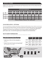 3
3
-
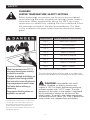 4
4
-
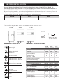 5
5
-
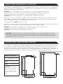 6
6
-
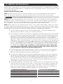 7
7
-
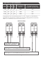 8
8
-
 9
9
-
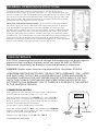 10
10
-
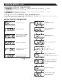 11
11
-
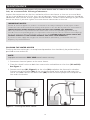 12
12
-
 13
13
-
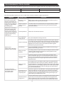 14
14
-
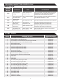 15
15
-
 16
16
-
 17
17
-
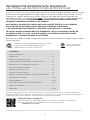 18
18
-
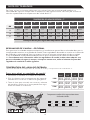 19
19
-
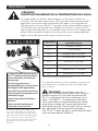 20
20
-
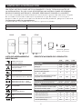 21
21
-
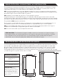 22
22
-
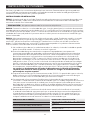 23
23
-
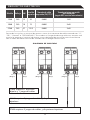 24
24
-
 25
25
-
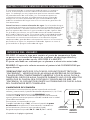 26
26
-
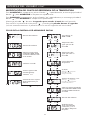 27
27
-
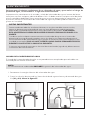 28
28
-
 29
29
-
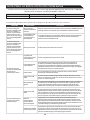 30
30
-
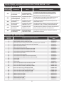 31
31
-
 32
32
-
 33
33
-
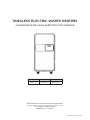 34
34
-
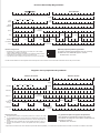 35
35
-
 36
36


EcoSmart ECOS 12 Manual de usuario
- Categoría
- Calentadores de agua
- Tipo
- Manual de usuario
en otros idiomas
- English: EcoSmart ECOS 12 User manual
Artículos relacionados
Otros documentos
-
Rheem RETEX-13 Manual de usuario
-
Ariston AURES PRO 27 240V US Manual de usuario
-
Craftsman CM-XTEPA0024 Manual de usuario
-
BLACK+DECKER BD-07-DWH Manual de usuario
-
ATMOR AT-912-29TP Manual de usuario
-
Bradley Keltech SNA Series Guía de instalación
-
Rheem RETEX-04 Manual de usuario
-