LG ATNQ30GPLA4 Guía de instalación
- Categoría
- Barbacoas
- Tipo
- Guía de instalación
Este manual también es adecuado para

INSTALLATION MANUAL
CEILING CASSETTE
AIR
CONDITIONER
www.lg.com
Please read this installation manual completely before installing the product.
Installation work must be performed in accordance with the national wiring
standards by authorized personnel only.
Please retain this installation manual for future reference after reading it
thoroughly.
P/NO.: MFL70520306
REV.00_190413
Copyright © 2016 - 2019 LG Electronics Inc. All Rights Reserved.
ENGLISH
ESPAÑOL

• Do not cool excessively indoors. This may be harmful for your health and may consume more
electricity.
• Block sunlight with blinds or curtains while you are operating the air conditioner.
• Keep doors or windows closed tightly while you are operating the air conditioner.
• Adjust the direction of the air flow vertically or horizontally to circulate indoor air.
• Speed up the fan to cool or warm indoor air quickly, in a short period of time.
• Open windows regularly for ventilation as the indoor air quality may deteriorate if the air conditioner
is used for many hours.
• Clean the air filter once every 2 weeks. Dust and impurities collected in the air filter may block the
air flow or weaken the cooling / dehumidifying functions.
For your records
Staple your receipt to this page in case you need it to prove the date of purchase or for warranty
purposes. Write the model number and the serial number here:
Model number :
Serial number :
You can find them on a label on the side of each unit.
Dealer’s name :
Date of purchase :
Here are some tips that will help you minimize the power consumption when you use the air
conditioner. You can use your air conditioner more efficiently by referring to the instructions
below:
TIPS FOR SAVING ENERGY
ENGLISH
TIPS FOR SAVING ENERGY
2

3
IMPORTANT SAFETY INSTRUCTIONS
READ ALL INSTRUCTIONS BEFORE USING THE APPLIANCE.
Always comply with the following precautions to avoid dangerous situations and ensure peak
performance of your product.
WARNING
It can result in serious injury or death when the directions are ignored.
CAUTION
It can result in minor injury or product damage when the directions are ignored.
WARNING
• Installation or repairs made by unqualified persons can result in hazards to you and others.
• Installation MUST conform with local building codes or, in the absence of local codes, with
the Nation Electrical Code NFPA 70/ANSI C1-1003 or current edition and Canadian Electrical
Code Part1 CSA C.22.1.
• The information contained in the manual is intended for use by a qualified service technician
familiar with safety procedures and equipped with the proper tools and test instruments.
• Failure to carefully read and follow all instructions in this manual can result in equipment
malfunction, property damage, personal injury and/or death.
Installation
• Always perform grounding.
- Otherwise, it may cause electrical shock.
• Don’t use a power cable, a plug or a loose socket which is damaged.
- Otherwise, it may cause a fire or electrical shock.
• For installation of the product, always contact the service center or a professional installation
agency.
- Otherwise, it may cause a fire, electrical shock, explosion or injury.
• Securely attach the electrical part cover to the indoor unit and the service panel to the outdoor unit.
- If the electrical part cover of the indoor unit and the service panel of the outdoor unit are not
attached securely, it could result in a fire or electric shock due to dust, water, etc.
• Always install an air leakage breaker and a dedicated switching board.
- No installation may cause a fire and electrical shock.
• Do not keep or use flammable gases or combustibles near the air conditioner.
- Otherwise, it may cause a fire or the failure of product.
• Ensure that an installation frame of the outdoor unit is not damaged due to use for a long time.
- It may cause injury or an accident.
• Do not disassemble or repair the product randomly.
- It will cause a fire or electrical shock.
• Do not install the product at a place that there is concern of falling down.
- Otherwise, it may result in personal injury.
• Use caution when unpacking and installing.
- Sharp edges may cause injury.
Operation
• Do not share the outlet with other appliances.
- It will cause an electric shock or a fire due to heat generation.
• Do not use the damaged power cable.
- Otherwise, it may cause a fire or electrical shock.
• Do not modify or extend the power cable randomly.
- Otherwise, it may cause a fire or electrical shock.
!
!
!
ENGLISH
IMPORTANT SAFETY INSTRUCTIONS

• Take care so that the power cable may not be pulled during operation.
- Otherwise, it may cause a fire or electrical shock.
• Unplug the unit if strange sounds, smell, or smoke comes from it.
- Otherwise, it may cause electrical shock or a fire.
• Keep the flames away.
- Otherwise, it may cause a fire.
• Take the power plug out if necessary, holding the head of the plug and do not touch it with wet
hands.
- Otherwise, it may cause a fire or electrical shock.
• Do not use the power cable near the heating tools.
- Otherwise, it may cause a fire and electrical shock.
• Do not open the suction inlet of the indoor/outdoor unit during operation.
- Otherwise, it may electrical shock and failure.
• Do not allow water to run into electrical parts.
- Otherwise, it may cause the failure of machine or electrical shock.
• Hold the plug by the head when taking it out.
- It may cause electric shock and damage.
• Never touch the metal parts of the unit when removing the filter.
- They are sharp and may cause injury.
• Do not step on the indoor/outdoor unit and do not put anything on it.
- It may cause an injury through dropping of the unit or falling down.
• Do not place a heavy object on the power cable.
- Otherwise, it may cause a fire or electrical shock.
• When the product is submerged into water, always contact the service center.
- Otherwise, it may cause a fire or electrical shock.
• Take care so that children may not step on the outdoor unit.
- Otherwise, children may be seriously injured due to falling down.
CAUTION
Installation
• Install the drain hose to ensure that drain can be securely done.
- Otherwise, it may cause water leakage.
• Install the product so that the noise or hot wind from the outdoor unit may not cause any damage to
the neighbors.
- Otherwise, it may cause dispute with the neighbors.
• Always inspect gas leakage after the installation and repair of product.
- Otherwise, it may cause the failure of product.
• Keep level parallel in installing the product.
- Otherwise, it may cause vibration or water leakage.
• Means for disconnection must be incorporated in the fixed wiring in accordance with the wiring
rules.
Operation
• Avoid excessive cooling and perform ventilation sometimes.
- Otherwise, it may do harm to your health.
• Use a soft cloth to clean. Do not use wax, thinner, or a strong detergent.
- The appearance of the air conditioner may deteriorate, change color, or develop surface flaws.
• Do not use an appliance for special purposes such as preserving animals vegetables, precision
machine, or art articles.
- Otherwise, it may damage your properties.
• Do not place obstacles around the flow inlet or outlet.
- Otherwise, it may cause the failure of appliance or an accident.
!
ENGLISH
IMPORTANT SAFETY INSTRUCTIONS
4

ENGLISH
5
2 TIPS FOR SAVING ENERGY
3 IMPORTANT SAFETY INSTRUCTIONS
6 INSTALLATION PLACES
7 THE INDOOR UNIT INSTALLATION
8 Indoor Unit Drain Piping
9 Wiring Connection
11 OPERATING INSTRUCTION
11 How to insert the Batteries
11 Wireless Remote Controller Maintenance
11 Operating Method
12 INSTALLATION OF DECORATIVE PANEL(ACCESSORY)
14 TEST RUNNING
15 INSTALLATION INSTRUCTIONS
15 Installer Setting - Setting Address of Central Control
15 Installer Setting - Checking Address of Central Control
16 Installer Setting -How to enter installer setting mode
17 Installer Setting - Installer Setting Code Table
TABLE OF CONTENTS
TABLE OF CONTENTS

6
ENGLISH
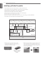
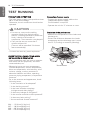
INSTALLATION PLACES
INSTALLATION PLACES
- There should not be any heat source or steam near the unit.
- There should not be any obstacles to prevent the air circulation.
- A place where air circulation in the room will be good.
- A place where drainage can be easily obtained.
- A place where noise prevention is taken into consideration.
- Do not install the unit near the door way.
- Ensure the spaces indicated by arrows from the wall, ceiling, or other obstacles.
- The indoor unit must keep the maintenance space.
Unit : mm
Ceiling
Ceiling Board
Ceiling Board
At least 10
800 or less
At least 1 800
3 600 or less (TP)
4 200 or less (TM/TN)
1 000
or more
500 or
more
500 or
more
300 or less
Floor
* Please use an annexed sheet or the
corrugated cardboard on the bottom of
packing as installation sheet.
* When using the bottom sheet, please use it
after separating the installation sheet from
packing of the product floor by using a knife
etc as a picture below.
Annexed sheet
Or
Packing corrugated
cardboard on the
bottom

ENGLISH
7
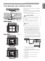
THE INDOOR UNIT INSTALLATION
Level gauge
Ceiling
Ceiling board
875(Ceiling opening)
787
684
671
875(Ceiling opening)
840
840
Panel size : 950 X 950 mm
Panel size : 700 X 700 mm
585~660(Ceiling opening)
517
461
517
585~660(Ceiling opening)
523
570
570
319
Panel size : 620 X 620 mm
600(Ceiling opening)
517
461
517
600(Ceiling opening)
523
570
570
319
CAUTION
!
• This air-conditioner uses a drain pump.
• Install the unit horizontally using a level
gauge.
• During the installation, care should be
taken not to damage electric wires.
- Select and mark the position for fixing bolts
and piping hole.
- Decide the position for fixing bolts slightly
tilted to the drain direction after considering
the direction of drain hose.
- Drill the hole for anchor bolt on the wall.
NOTE
!
Avoid the following installation location.
1 Such places as restaurants and kitchen
where considerable amount of oil steam
and flour is generated. These may cause
heat exchange efficiency reduction, or
water drops, drain pump mal-function. In
these cases, take the following actions;
- Make sure that ventilation fan is enough
to cover all noxious gases from this place.
- Ensure enough distance from the cooking
room to install the air conditioner in such
a place where it may not suck oily steam.
2 Avoid installng air conditioner in such
places where cooking oil or iron powder is
generated.
3 Avoid places where inflammable gas is
generated.
4 Avoid place where noxious gas is
generated.
5 Avoid places near high frequency
generators.
Cooking table
Air conditioner
Take enough
distance
Use the ventilation fan for smoke-collecting
hood with sufficient capacity.
THE INDOOR UNIT INSTALLATION
[TM/TN/TP Chassis] (Unit:mm)
[TQ/TR Chassis] (Unit:mm)

8
ENGLISH
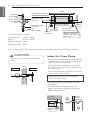
THE INDOOR UNIT INSTALLATION
Set screw of
paper model (4 pieces)
Paper model
for installation
Ceiling
board
150 mm
Ceiling board
Ceiling
Flat washer for M10
(accessory)
Keep the length of the bolt
from the bracket to 40 mm
Open the ceiling board
along the outer edge of the
paper model
Flat washer for M10
(accessory)
Hanging bolt
(W 3/8 or M10)
Nut
(W 3/8 or M10)
Nut
(W 3/8 or M10)
Spring washer
(M10)
Air Conditioner body
Keep the length of 15~18 mm
between the air conditioner
bottom surface and the ceiling
surface
Adjust the
same height
The following parts is option.
① Hanging Bolt - W 3/8 or M10
② Nut - W 3/8 or M10
③ Spring Washer - M10
④ Plate Washer - M10
Drill the piping hole on the wall slightly tilted to the outdoor side using a Ø 70 hole-core drill.
Wall
Indoor
Outdoor
5~7 mm
CAUTION
!
Tighten the nut and bolt to prevent unit
falling.
Maintenance
drain port
Upward
routing
not allowed
Pipe clamp
Indoor unit
300 mm or less
Indoor Unit Drain Piping
- Drain piping must have down-slope (1/50 to
1/100): be sure not to provide up-and-down
slope to prevent reversal flow.
- During drain piping connection, be careful
not to exert extra force on the drain port on
the indoor unit.
- The outside diameter of the drain connection
on the indoor unit is 32 mm.
- Be sure to execute heat insulation on the
drain piping.
- Install the drain raising pipes at a right
angle to the indoor unit and no more than
300 mm from the unit.
Piping material: Polyvinyl chloride pipe
VP-25 and pipe fittings

ENGLISH
9
THE INDOOR UNIT INSTALLATION
700 or less
1 -1.5 m
Clamp metal(attached) Drain hose(attached)
Drain raising pipe
300 mm or less300 mm or less300 mm or less
Heat insulation material: Polyethylene
foam with thickness more than 8 mm.
Drain test
The air conditioner uses a drain pump to drain
water.
Use the following procedure to test the drain
pump operation:
- Connect the main drain pipe to the exterior
and leave it provisionally until the test comes
to an end.
- Feed water to the flexible drain hose and
check the piping for leakage.
- Be sure to check the drain pump for normal
operating and noise when electrical wiring is
complete.
- When the test is complete, connect the
flexible drain hose to the drain port on the
indoor unit.
Feed
water
Drain Pump
Drain pan
Flexible drain hose
(accessory)
Main
drain pipe
Glue the joint
Drain
port
Drain hose connection
Use the clip (accessory)
HEAT INSULATION
- Use the heat insulation material for the
refrigerant piping which has an excellent
heat-resistance (over 120 °C).
- Precautions in high humidity circumstance:
This air conditioner has been tested
according to the "KS Standard Conditions
with Mist" and confirmed that there is not
any default. However, if it is operated for a
long time in high humid atmosphere (dew
point temperature: more than 23 °C), water
drops are liable to fall. In this case, add heat
insulation material according to the following
procedure:
- Heat insulation material to be prepared...
Adiabatic EPDM or NBR with thickness 10 to
20 mm.
- Stick glass wool on all air conditioners that
are located in ceiling atmosphere.
Indoor
unit
Thermal insulator
(accessory)
Fastening band
(accessory)
Refrigerant
piping
Wiring Connection
- Open the control box cover and connect the
Remote controller cable and Indoor power
wires.
- Remove the control box cover for electrical
connection between the indoor and outdoor
unit. (Remove screws
①
)
- Use the cord clamper to fix the cord.
Remote
controller
cable
1
1
Connection
cord
between the
indoor unit and
the outdoor
unit
Control box cover
(On which the
Electric Wiring
Connection is put)
CAUTION
!
The supplied flexible drain hose should not
be curved, neither screwed. The curved or
screwed hose may cause a leakage of
water.
1/50~1/100 slope
Hanger
distance
Hanger Bracket
Max 700 mm
Flexible drain hose
Insulation
Metal
clamp
Max 300 mm
1~15 m

10
ENGLISH
THE INDOOR UNIT INSTALLATION
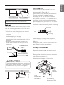
Precautions when laying power
wiring
Use round pressure terminals for connections
to the power terminal block.
When none are available, follow the
instructions below.
- Do not connect wiring of different
thicknesses to the power terminal block.
(Slack in the power wiring may cause
abnormal heat.)
- When connecting wiring which is the same
thickness, do as shown in the figure below.
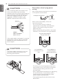
CAUTION
!
The connecting cable connected to the
indoor and outdoor unit should be
complied with the following specifications
(This equipment shall be provided with a
cable set complying with the national
regulation). (Rubber insulation, type
H05RN-F approved by HAR or SAA).
CAUTION
!
The Power cable connected to the unit
should be selected according to the
following specifications.
If the supply cable is damaged, it must be
replaced by a special cable or assembly
available from the manufacturer of its
service agent.
NORMAL
CROSS-SECTIONAL
AREA 0.75 mm
2
20 mm
35±5 mm
GN/YL
10±3 mm
Power wirer
Round pressure terminal
Connect same thickness
wiring to both sides.
It is forbidden to
connect two to one
side.
It is forbidden to
connect wiring of
different thicknesses.
- For wiring, use the designated power wire
and connect firmly, then secure to prevent
outside pressure being exerted on the
terminal block.
- Use an appropriate screwdriver for tightening
the terinal screws. A screwdriver with a
small head will strip the head and make
proper tighterning impossible.
- Over-tightening the terminal screws may
break them.

ENGLISH
11
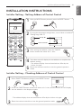
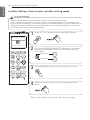
OPERATING INSTRUCTION
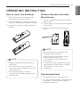
How to insert the Batteries
1 Remove the battery cover by pulling it
according to the arrow direction.
2 Insert new batteries making sure that the
(+) and (-) of battery are installed correctly.
3 Reattach the cover by sliding it back into
position.
Wireless Remote Controller
Maintenance
1 Choose a suitable place where its safe &
easy to reach.
2 Fix the holder to wall etc with the supplied
screws firmly.
3 Slide the remote controller inside the
holder.
Operating Method
1 The signal receiver is inside the unit.
2 Aim the remote controller towards the unit
to operate it. There should not be any
blockage in between.
NOTE
!
• Always use/replace both batteries of
same type.
• If the system is not to be used for a
long time, remove the batteries to save
their working life.
• If the display screen of remote
controller starts, fading replace both of
the batteries.
NOTE
!
• Remote controller should never be
exposed to direct sunlight.
• Signal transmitter & receiver should
always be clean for proper
communication. Use a soft cloth to
clean them.
• In case some other appliances also get
operated with remote control, change
their position or consult your
serviceman.
OPERATING INSTRUCTION

12
ENGLISH
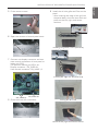
INSTALLATION OF DECORATIVE PANEL(ACCESSORY)
INSTALLATION OF DECORATIVE PANEL(ACCESSORY)
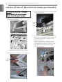
The decorative panel has its installation
direction.
Before installing the decorative panel,
always remove the paper template.
1 Remove the packing and take out air inlet
grille from front panel.
4 Insert two screws on diagonal corners of
panel. Do not tighten the bolts completely.
(The fixing screws are included in the
indoor unit box.)
Check the alignment of panel with the
ceiling. Height can be adjusted using
hanging bolts as shown in picture. Insert
the other two screws and tighten all
screws completely.
Separate the link from the front grill
Coner
cover
Hook
clip
Hook
2 Remove the Corner covers of the panel.
3 Fit the panel on the unit by inserting hooks
as shown in picture.

ENGLISH
INSTALLATION OF DECORATIVE PANEL(ACCESSORY)
5 Fit the corner covers.
Screw
Installing the grill link on the panel body
Inserting the edge into the panel body
Closing the door lock
Check the left, right and central sections
CN_VANE 1,2
CN_DISPLAY
6 Open two screws of control panel cover.
7 Connect one display connector and two
vane control connectors of front panel to
indoor unit PCB.
The position marking on PCB is as:
Display connector : CN_DISPLAY
Vane control connector: CN_VANE 1,2
8 Close the cover for control box.
9 Install the air inlet grille and Filter on the
panel.
- After inserting the edge of the grill into
the panel body, close the door lock and
press on the left, right, and center
sections.

14
ENGLISH
TEST RUNNING
PRECAUTIONS IN TEST RUN
- The initial power supply must provide at least
90 % of the rated voltage.
Otherwise, the air conditioner should not be
operated.
Connection of power supply
- Connect the power supply cable to the
independent power supply.
Circuit breaker is required.
- Operate the unit for 15 minutes or more.
CHECK THE FOLLOWING ITEMS WHEN
INSTALLATION IS COMPLETED
- After completing work, be sure to measure
and record trial run properties, and store
measured data, etc.
- Measuring items are room temperature,
outside temperature, suction temperature,
blow out temperature, wind velocity, wind
volume, voltage, current, presence of
abnormal vibration and noise, operating
pressure, piping temperature, compressive
pressure.
- As to the structure and appearance, check
following items.
* Is the circulation of air adequate?
* Is the draining smooth?
* Is the heat insulation complete
(refrigerant and drain piping)?
* Is there any leakage of refrigerant?
* Is the remote controller switch operated?
* Is there any faulty wiring?
* Are not terminal screws loosened?
M4......118 N·cm{12 kgf·cm}
M5......196 N·cm{20 kgf·cm}
M6......245 N·cm{25 kgf·cm}
M8......588 N·cm{60 kgf·cm}
- To cancel the test run, press any button.
CAUTION
!
• For test run, carry out the cooling
operation firstly even during heating
season. If heating operation is carried out
firstly, it leads to the trouble of
compressor. Then attention must be paid.
• Carry out the test run more than 5
minutes without fail.
(Test run will be cancelled 18 minutes
later automatically)
Evaluation of the performance
- Measure the temperature of the intake and
discharge air.
- Ensure the difference between the intake
temperature and the discharge one is more
than 8 °C (Cooling) or reversely (Heating).
Thermometer
TEST RUNNING

INSTALLATION INSTRUCTIONS
ENGLISH
15
Installer Setting - Checking Address of Central Control
(3 s)
˚C / ˚F (5 s)
With the MODE button pressed, press the RESET button.
1
By using the temperature setting button, set the indoor unit address.
- Setting range : 00 ~ FF
2
After setting the address, press the ON/OFF
button toward the indoor unit 1 time.
3
The indoor unit will display the set address to complete the
address setting.
- The address display time and method can differ by the
indoor uint type.
Reset the remote controller to use the general operation
mode.
4
5
Group No.
Indoor Unit No.
When FUNCTION button pressed, press RESET button
1
Press the ON/OFF button toward the indoor unit 1 time, and the indoor unit will display
the set address in the display window.
- The address display time and method can differ by the indoor unit type.
2
Reset the remote controller to use the general operation mode.
3
INSTALLATION INSTRUCTIONS
Installer Setting - Setting Address of Central Control

Installer Setting -How to enter installer setting mode
CAUTION
!
Installer setting mode is to set the detail function of the remote controller.
If the installer setting mode is not set correctly, it can cause problems to the product, user
injury or property damage. This must be set by an certificated installer, and any installation or
change that is carried out by a non-certificated person should be responsible for the results.
In this case, free service cannot be provided.
(3 s)
˚C / ˚F (5 s)
When JET COOL button pressed, press RESET button
1
By using the TEMPERATURE SETTING button, set function
code and setting value. (Please refer the Installer Setting
Code Table.)
2
Function Code
Setting Code
Press the ON/OFF button toward the indoor unit 1 time.
3
Reset the remote controller to use the general operation
mode.
* Refer to the Installer Setting Code Table on the next page.
4
ENGLISH
INSTALLATION INSTRUCTIONS
16

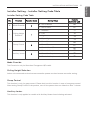
Installer Setting - Installer Setting Code Table
Installer Setting Code Table
No. Function Function Code Setting Value
Remote
Controller LCD
0 Mode Override
0
0 : Set to Master
00
1 : Set to Slave
01
1
Ceiling Height
Selection
1
1 : Standard
11
2 : Low
12
3 : High
13
4 : Super High
14
2
Group Control
2
0 : Set to Master
20
1 : Set to Slave
21
2 : Check Master/Slave
22
Auxiliary heater
2
3 : Set to Auxiliary heater
23
4 : Cancel Auxiliary heater
24
2 : Check Auxiliary heater Installation
25
Mode Override
This Function is only for Non-Auto Changeover H/P model.
Ceiling Height Selection
Indoor unit connected to wired remote controller operate as wired remote controller setting.
Group Control
This function is only for group control. Please don’t set this function in case of non-group control.
After setting Group Control of the product, turn off the power then turn it back on after 1 minute.
Auxiliary heater
This function is only applied to models with Auxiliary Heater function being activated.
17
ENGLISH
INSTALLATION INSTRUCTIONS

18
ENGLISH

MANUAL DE INSTALACIÓN
AIRE
ACONDICIONADO
www.lg.com
Asegúrese de leer las precauciones de seguridad antes de la instalación y uso, y
utilícelo correctamente.
Se ha diseñado para proteger la seguridad del instalador y el usuario y evitar daños
materiales, etc.
Tras leer el manual de usuario, guárdelo en un lugar donde pueda consultarlo en
cualquier momento.
Favor leer este manual de instalacion completamente antes de instalar el producto.
La instalacion debe ser realizada de acuerdo a los codigos electricos locales
solamente por personall autorizado.
Por favor guardar este manual despues de leerlo para futuras referencias.
CASSETTE
Copyright © 2016 - 2019 LG Electronics Inc. Todos los derechos reservados.
ESPAÑOL

• No enfríe excesivamente los espacios. Puede ser nocivo para su salud y consumirá más
electricidad.
• Evite el paso de la luz solar con persianas o cortinas cuando esté utilizando el aire acondicionado.
• Mantenga las puertas y ventanas bien cerradas mientras tenga en funcionamiento el aire
acondicionado.
• Ajuste la dirección del flujo de aire vertical u horizontalmente para que circule el aire en el interior.
• Aumente la velocidad del ventilador para enfriar o calentar el aire interior con rapidez y en un
periodo corto de tiempo.
• Abra las ventanas con regularidad para ventilar, porque la calidad del aire interior puede
deteriorarse si se utiliza el aire acondicionado durante muchas horas.
• Limpie el filtro del aire una vez cada dos semanas. El polvo y las impurezas recogidas en el filtro
de aire puede bloquear el flujo de aire o debilitar las funciones de refrigeración /
deshumidificación.
Como referencia
Engrape la factura de compra en esta página, ya que será su prueba de compra para la garantía.
Escriba aquí el número de modelo y el número de serie:
Número de modelo:
Número de serie:
Los encontrará en una etiqueta en el lateral de cada unidad.
Nombre del distribuidor:
Fecha de compra:
Estos consejos le ayudarán a reducir el consumo de energía cuando utilice el aire acondicionado.
Podrá utilizar el aparato de aire acondicionado de forma eficiente siguiendo estas instrucciones:
CONSEJOS PARA AHORRAR ENERGÍA
ESPAÑOL
CONSEJOS PARA AHORRAR ENERGÍA
2

3
INSTRUCCIONES DE SEGURIDAD IMPORTANTES
LEA TODAS LAS INSTRUCCIONES ANTES DE UTILIZAR EL PRODUCTO
Cumpla con las siguientes precauciones para evitar situaciones de peligro y garantizar un funcionamiento
óptimo de su producto.
ADVERTENCIA
Puede sufrir lesiones de gravedad o mortales si ignora las instrucciones.
PRECAUCIÓN
Puede sufrir lesiones menores o dañar el producto si ignora las instrucciones.
ADVERTENCIA
• Las instalaciones o reparaciones realizadas por personas no cualificadas pueden dar lugar a peligros para
usted y otras personas.
• La instalación DEBE cumplir con los códigos de construcción locales o, a falta de ellos, con el Código
Nacional Eléctrico NFPA 70/ANSI C1-1003 o la edición actual del Código Eléctrico Canadiense Parte 1
CSA C.22.1.
• La información de este manual está dirigida a personal técnico cualificado, familiarizado con los
procedimientos de seguridad y equipado con las herramientas e instrumentos de prueba adecuados.
• Lea detenidamente y cumpla con todas las instrucciones de este manual. De lo contrario, el aparato
podría no funcionar correctamente, o producirse lesiones graves o mortales y daños materiales.
Instalación
• Realice siempre la conexión de la toma de tierra.
- Si no lo hace, podría producirse una descarga eléctrica.
• No utilice un cable de alimentación, un conector o un enchufe flojo que estén dañados.
- Si lo hace, podría producirse un incendio o descarga eléctrica.
• Para la instalación del producto, póngase siempre en contacto con el centro de servicio técnico o con una
empresa de instalaciones especializada.
- De lo contrario, podría producirse un incendio, descarga eléctrica, explosión o daños.
• Ajuste firmemente la cubierta de la parte eléctrica en la unidad interior y el panel de servicio en la unidad
exterior.
- Si la cubierta de la parte eléctrica de la unidad interior y el panel de servicio de la unidad exterior no están
ajustados firmemente, podría producirse un incendio o descarga eléctrica debido al polvo, agua, etc.
• Instale siempre un disyuntor electrico dedicado en el panel electrico.
- Si no lo instala, podría producirse un incendio y una descarga eléctrica.
• No almacene ni utilice gases inflamables o combustibles cerca del aire acondicionado.
- De lo contrario, podría producirse un incendio o una avería del aparato.
• Asegúrese de que el bastidor de instalación de la unidad exterior no está dañado debido a un uso prolongado.
- Podría producir daños o un accidente.
• No desarme ni repare los productos sin causa justificada.
- Podría producirse un incendio o una descarga eléctrica.
• No instale el aparato en un lugar donde pueda caerse.
- De lo contrario, podrían producirse daños personales.
• Tenga cuidado cuando lo desempaque e instale.
- Los bordes afilados pueden producir daños.
• No encienda el disyuntor ni la alimentación en caso de que el panel frontal, el gabinete, la cubierta superior o la
cubierta de la caja de control se hayan extraído o abierto.
- De lo contrario, podría producirse un incendio, una descarga eléctrica, una explosión o incluso la muerte.
Funcionamiento
• No comparta el enchufe con otros aparatos.
- Podría producirse una descarga eléctrica o incendio debido a la generación de calor.
!
!
!
INSTRUCCIONES DE SEGURIDAD IMPORTANTES
ESPAÑOL

• No utilice un cable de alimentación dañado.
- Si lo hace, podría producirse un incendio o una descarga eléctrica.
• No modifique ni alargue el cable de alimentación sin causa justificada.
- Si lo hace, podría producirse un incendio o una descarga eléctrica.
• Tenga cuidado de no estirar el cable de alimentación durante el funcionamiento.
- Si lo hace, podría producirse un incendio o una descarga eléctrica.
• Desenchufe la unidad si emite un sonido extraño, olores o humo.
- Si no lo hace, podría producirse una descarga eléctrica o un incendio.
• Manténgala alejada de llamas.
- De lo contrario, podría producirse un incendio.
• Si es necesario desenchufar el cable de alimentación, hágalo sujetando la cabeza de la clavija y no lo toque con
las manos húmedas.
- De lo contrario, podría producirse un incendio o una descarga eléctrica.
• No utilice el cable de alimentacion cerca de generadores de calor.
- Si lo hace, podría producirse un incendio o una descarga eléctrica.
• No abra la entrada de aire de la unidad interior/exterior durante el funcionamiento.
- Si lo hace, podría producirse una descarga eléctrica y una avería.
• No permita que entre agua en las partes eléctricas.
- De lo contrario, podría producirse una avería en la unidad o una descarga eléctrica.
• Sujete la clavija por la cabeza cuando la saque.
- Podría producirse una descarga eléctrica y daños.
• No toque nunca las partes metálicas de la unidad cuando retire el filtro.
- Son afiladas y pueden producir lesiones.
• No se suba sobre la unidad interior/exterior ni coloque nada sobre ellas.
- Podrían producirse daños debido al desplome o caída de la unidad.
• No coloque ningún objeto pesado sobre el cable de alimentación.
- Si lo hace, podría producirse un incendio o una descarga eléctrica.
• Si el aparato se ha sumergido en agua, póngase siempre en contacto con el centro de servicio técnico.
- De lo contrario, podría producirse un incendio o una descarga eléctrica.
• Vigile que los niños no se suban a la unidad exterior.
- Si lo hacen, podrían resultar gravemente lesionados debido a una caída.
PRECAUCIÓN
Instalación
• Instale la manguera de drenaje para asegurar que el drenaje pueda realizarse correctamente.
- De lo contrario, podrían producirse fugas de agua.
• Instale el aparato de modo que el ruido o el aire caliente procedente de la unidad exterior no cause molestias a
los vecinos.
- De lo contrario, podrían producirse disputas con los vecinos.
• Compruebe siempre si existen pérdidas de gas después de instalar o reparar la unidad.
- Si no lo hace, podría producirse una avería en la unidad.
• Instale la unidad bien nivelada.
- Si no lo hace, podrían producirse vibraciones o fugas de agua.
• Los medios para la desconexión deben ser incorporados en el cableado fijo de acuerdo con las reglas de
cableado.
Funcionamiento
• Evite un enfriamiento excesivo y ventile frecuentemente.
- De lo contrario, podría perjudicar su salud.
• Utilice un paño suave para limpiar la unidad. No utilice cera, disolvente ni un detergente fuerte.
- Podría deteriorarse el aspecto del aire acondicionado, cambiar el color o producirse desperfectos en su
superficie.
• No utilice el aparato para una finalidad especial como el acondicionamiento para animales o vegetales,
máquinas de precisión o la conservación de artículos de arte.
- Si lo hace, podrían producirse daños en sus propiedades.
• No coloque ningún obstáculo alrededor de las entradas o salidas de aire.
- Si lo hace, podría producirse una avería en el aparato o un accidente.
!
ESPAÑOL
INSTRUCCIONES DE SEGURIDAD IMPORTANTES
4

5
2 CONSEJOS PARA AHORRAR ENERGÍA
3 INSTRUCCIONES DE SEGURIDAD IMPORTANTES
6 ELECCIÓN DE LA MEJOR UBICACIÓN
7 INSTALACIÓN DE LA UNIDAD INTERIOR
8 Tubería de drenaje de la unidad interior
9 Conexión de cableado
11 INSTRUCCIONES DE FUNCIONAMIENTO
11 Inserción de pilas
11 Mantenimiento del control remoto
11 Método de operación
12 INSTALACIÓN DEL PANEL DECORATIVO (ACCESORIOS)
14 PRUEBA DE FUNCIONAMIENTO
15 INSTRUCCIONES DE INSTALACIÓN
15 Configuración del instalador - Ajuste de direcciones de control central
15 Configuración del instalador - Comprobación de la dirección del control central
16 Configuración del instalador - Entrar en el modo de configuración de instalador
17 Configuración del instalador - Tabla de códigos de ajuste de instalador
ÍNDICE
ÍNDICE
ESPAÑOL

6
ESPAÑOL
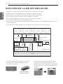
ELECCIÓN DE LA MEJOR UBICACIÓN
ELECCIÓN DE LA MEJOR UBICACIÓN
- Cerca de la unidad no debe existir ninguna fuente de calor o de vapor.
- No debe existir ningún obstáculo que impida la circulación del aire.
- Elija un lugar de la habitación donde haya buena circulación de aire.
- Elija un lugar donde se facilite un buen desagüe a la unidad.
- Elija un lugar teniendo en cuenta el ruido que produce el aparato.
- No instale la unidad cerca de una puerta de paso.
- Asegúrese de que existen los espacios libres indicados por las flechas desde la pared, el techo
u otros obstáculos.
- La unidad interior debe disponer de un espacio suficiente para su mantenimiento.
Unidad : mm
Techo
Placa de techo
Placa de techo
Más de 10
800 o menos
Más de 1 800
3 600 o menos (TP)
4 200o menos (TM/TN)
1 000
o más
500
o más
500
o más
300 o menos
Suelo
* Utilice la lámina que se adjunta o el cartón
ondulado del fondo del embalaje como
lámina de instalación.
* Cuando utilice la lámina del fondo, hágalo
tras separar la lámina de instalación del
embalaje de la base del producto cortándola
con un cuchillo, etc. como se muestra en la
imagen.
Lámina incluida
O
Cartón de embalaje
ondulado del fondo

7
ESPAÑOL
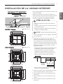
INSTALACIÓN DE LA UNIDAD INTERIOR
Indicador
de nivel
Techo
Panel del techo
875(Abertura en techo)
787
684
671
875(Abertura en techo)
840
840
Tamaño del panel : 950 X 950 mm
Tamaño del panel : 700 X 700 mm
585~660(Abertura en techo)
517
461
517
585~660(Abertura en techo)
523
570
570
319
Tamaño del panel : 620 X 620 mm
600(Abertura en techo)
517
461
517
600(Abertura en techo)
523
570
570
319
PRECAUCIÓN
!
• Este aire acondicionado utiliza una bomba de
drenaje.
• Instale la unidad en posición horizontal utilizando
un indicador de nivel.
• Durante la instalación, deberá tener cuidado de
no dañar los cables eléctricos.
- Elija y marque la posición de los pernos de fijación y del
orificio de entubado.
- Determine la posición de los pernos de fijación con
ligera inclinación hacia la dirección de drenaje, teniendo
en cuenta la dirección de la manguera de drenaje.
- Perfore en la pared el orificio del perno de fijación.
NOTA
!
Evite la instalación en los lugares indicados
a continuación.
1 Restaurantes y cocinas en los que exista una
cantidad considerable de vapor de grasa y en los
que se genere polvo. Estas circunstancias pueden
disminuir la eficacia de intercambio de calor, goteo
de agua o provocar el funcionamiento incorrecto de
la bomba de drenaje. En estos casos, tome las
siguientes medidas:
- Asegúrese de que el aparato de ventilación tiene
la capacidad suficiente para todos los gases
tóxicos generados en este tipo de lugares.
- Asegúrese de que la distancia a la cocina es
suficiente e instale el aire acondicionado en un
lugar en el que no aspire vapor con grasas.
2 Intente no instalar el aire acondicionado en lugares
en los se generen grasas o polvo de hierro.
3 Evite los lugares en los que se produzcan gases
inflamables.
4 Evite los lugares en los que se produzcan gases
nocivos.
5 Evite los lugares cercanos a generadores de alta
frecuencia.
Tabla de Cocina
Aire acondicionado
Mantenga la
distancia
suficiente
Utilice el aparato de ventilación para extracción
de humos con capacidad suficiente.
INSTALACIÓN DE LA UNIDAD INTERIOR
[TM/TN/TP Chassis] (Unidad :mm)
[TQ/TR Chassis] (Unidad :mm)

8
ESPAÑOL
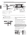
INSTALACIÓN DE LA UNIDAD INTERIOR
Tornillo de fijación del
modelo de papel
(4 unidades)
Modelo de papel
para la instalación
Placa
de techo
150 mm
Placa de techo
Techo
Arandela plana
para M10
(accesorio)
Mantenga la longitud del perno
desde la abrazadera de 40 mm
Abra la placa del techo a
lo largo del borde exterior
del modelo de papel.
Arandela plana para
M10 (accesorio)
Perno de
suspensión
(W 3/8 o M10)
Tuerca
(W 3/8 o M10)
Tuerca
(W 3/8 o M10)
Arandela de
resorte (M10)
Air Conditioner
body
Mantenga la longitud de
15-18 mm entre la superficie
inferior del aparato de aire
acondicionado y la
superficie del techo.
Ajuste la
misma altura
Las piezas siguientes son opcionales:
① Perno de suspensión - W 3/8 o M10
② Tuerca - W 3/8 o M10
③ Arandela de resorte - M10
④ Arandela plana - M10
Taladre en la pared el orificio de la tubería ligeramente inclinado hacia el exterior utilizando una
broca Ø 70.
Pared
Interior
Exterior
5~7 mm
PRECAUCIÓN
!
Apriete la tuerca y el perno para evitar el
desprendimiento de la unidad.
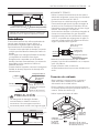
Acceso para
mantenimiento
de drenaje
Recorrido
ascendente
no permitido
Abrazadera de tubo
Unidad interior
300 mm o menos
Tubería de drenaje de la unidad
interior
- La tubería de drenaje debe estar inclinada hacia
abajo (1/50 a 1/100): para evitar la inversión del
flujo, asegúrese de que no existe una
inclinación hacia arriba y hacia abajo.
- Durante la conexión de la tubería de drenaje,
tenga cuidado de no ejercer demasiada fuerza
en el puerto de drenaje de la unidad interior.
- El diámetro exterior de la conexión de drenaje
en la unidad interior es 32 mm.
- Asegúrese de realizar el aislamiento térmico en
la tubería de drenaje.
- Instale los tubos de elevación del desagüe en
un ángulo recto con respecto a la unidad
interior y a una distancia de la unidad no
superior a los 300 mm.
Material de la tubería: Tubo de cloruro de
polivinilo VP-25 y adaptadores del tubo.

9
ESPAÑOL
INSTALACIÓN DE LA UNIDAD INTERIOR
700 o menos
1 -1,5 m
Abrazadera metálica (montada) Manguera de desagüe (montada)
Tubería ascendente de desagüe
300 mm o menos300 mm o menos300 mm o menos
Material del aislamiento térmico: espuma de
polietileno con un espesor superior a 8 mm.
Prueba de Drenaje
El acondicionador de aire utiliza una bomba de
drenaje para desaguar el agua. Utilice el
procedimiento siguiente para comprobar el
funcionamiento de la bomba de drenaje:
- Conecte el tubo principal de drenaje al exterior
y déjelo provisionalmente hasta que finalice la
prueba.
- Vierta agua en la manguera flexible de drenaje
y compruebe si la tubería tiene fugas.
- Asegúrese de comprobar que la bomba de
drenaje funciona correctamente y la existencia
de posibles ruidos cuando se finalice el
cableado eléctrico.
- Cuando finalice la prueba, conecte la manguera
flexible de drenaje al puerto de drenaje de la
unidad interior.
Agua
Bomba de drenaje
Bandeja de drenaje
Manguera flexible de
drenaje (accesorio)
Tubo principal
de drenaje
Pegue la unió
Puerto de
drenaje
Conexión de la manguera
de drenaje
Utilice el clip (accesorio)
AISLAMIENTO TÉRMICO
- Utilice el material de aislamiento térmico para la
tubería del refrigerante ya que tiene una excelente
resistencia térmica (más de 120 °C).
- Precauciones en condiciones de gran humedad:
Este acondicionador de aire ha sido ensayado de
acuerdo con las Condiciones Estándares KS con
Humedad y se ha confirmado que no tiene ningún
defecto. Sin embargo, si se pone en
funcionamiento durante un periodo prolongado de
tiempo en una atmósfera con gran humedad
(temperatura del punto de condensación superior
a 23 °C), es posible que caigan gotas de agua. En
este caso, añada material de aislamiento térmico
según el procedimiento siguiente:
- Material de aislamiento térmico que se debe
preparar: Lana de vidrio adiabático con un espesor
entre 10 y 20 mm.
- Pegue la lana de vidrio en todos los
acondicionadores de aire que estén ubicados en el
techo.
Conexión de cableado
- Abra la tapa de la caja de control y conecte el
cable del mando a distancia y los cables de
alimentación de la unidad interior.
- Retire la tapa de la caja de control para posibilitar
la conexión eléctrica entre la unidad de interior y la
exterior. (Quitar los tornillos ①)
- Utilice la pinza de fijación del cable
.
Unidad
Interior
Aislamiento térmico
(accesorio)
Cinta de sujeción
(accesorio)
Tubería del
refrigerante
Cable del
mando a
distancia
1
1
Cable de
conexión entre
la unidad
interior y
la exterior.
Tapa de la caja de control
(En cuál se coloca la conexión
del cableado eléctrico)
PRECAUCIÓN
!
La manguera de desagüe flexible
suministrada no debería torcerse ni
enroscarse. Una manguera torcida o
enroscada puede causar una fuga de agua.
Distancia al
colgador
Soporte del colgador
con inclinación
1/50 - 1/100
Max 700 mm
Manguera de desagüe flexible
Aislamiento
AbrazaderaAbrazadera
metálicametálica
Abrazadera
metálica
Max 300 mm
1~15 m

10
ESPAÑOL
INSTALACIÓN DE LA UNIDAD INTERIOR
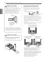
Precauciones de colocación del
cableado de corriente eléctrica
Utilice terminales de presión redondos para
las conexiones al bloque del terminal de
corriente.
Cuando no estén disponibles, sigua las
instrucciones que se exponen a continuación.
- No conecte cableado eléctrico con diferentes
grosores al bloque de terminales de corriente
eléctrica. (Las holguras en el cableado
eléctrico pueden ocasionar un calentamiento
anormal.)
- Al conectar un cableado eléctrico del mismo
grosor, siga estas instrucciones:
PRECAUCIÓN
!
El cable de conexión conectado a las
unidades interior y exterior deben cumplir
las siguientes especificaciones (Este
equipo debe suministrarse con un set de
cables que cumplan la normativa
nacional.) (Aislamiento de goma, tipo
H05RN-F aprobado por HAR o SAA)
PRECAUCIÓN
!
El cable de alimentación conectado a la
unidad debería seleccionarse según las
siguientes especificaciones.
Si el cable de alimentación está dañado,
debe ser sustituido por un cable especial
o por un conjunto que se puede conseguir
en el fabricante o en su servicio oficial.
ÁREA NORMAL
DE LA SECCIÓN
TRANSVERSAL
0,75 mm
2
20 mm
35±5 mm
GN/YL
10±3 mm
Cable de
corriente eléctrica
Terminal de presión redondo
Se prohíbe conectar
dos cables a la misma
extremidad.
Se prohíbe conectar
cableados de
diferente espesor.
Conecte un cableado del
mismo espesor a ambas
extremidades.
- Para el cableado, use el cable de alimentación
designado y conéctelo firmemente, a
continuación, fíjelo para evitar que la presión
exterior afecte al bloque de terminales.
- Use un destornillador adecuado para apretar los
tornillos del terminal. Un destornillador con una
punta pequeña dañaría la cabeza y haría
imposible un apretado adecuado.
- Apretar demasiado los tornillos de los
terminales podría romperlos.

11
ESPAÑOL
INSTRUCCIONES DE FUNCIONAMIENTO
Inserción de pilas
1 Desmonte la tapa de la batería tirando de
ella en la dirección de la flecha.
2 Inserte las nuevas pilas asegurándose de
que los signos (+) y (-) de la pila están
instalados correctamente.
3 Monte de nuevo la tapa deslizándola
nuevamente a su posición.
Mantenimiento del control
remoto
1 Seleccione una ubicación segura y de fácil
acceso para éste.
2 Fije el soporte a la pared mediante los
tornillos incluidos.
3 Deslice el mando a distancia en su
soporte.
Método de operación
1 El receptor de señal está dentro de la
unidad.
2 Apunte con el mando a distancia hacia la
unidad para operarla. No debe haber
obstáculos en la línea de visión.
NOTA
!
• Utilice/Sustituya siempre ambas pilas
por otras del mismo tipo.
• Si no piensa utilizar el sistema durante
un largo período de tiempo, retire las
pilas a fin de extender su vida útil.
• Si la información en la pantalla del
mando a distancia comenzara a
desvanecerse, sustituya ambas pilas.
NOTA
!
• El mando a distancia nunca debe ser
expuesto a la luz directa del sol.
• Debe mantener siempre limpio el
transmisor/receptor de señal a fin de
asegurar una correcta comunicación.
Emplee un paño suave para limpiarlo.
• Si el mando a distancia opera además
otros equipos, cambie su posición o
consulte al técnico de servicio.
INSTRUCCIONES DE FUNCIONAMIENTO

12
Separe el eslabón de la rejilla frontal
Cubre
esquinas
Clip de
enganche
Gancho
ESPAÑOL
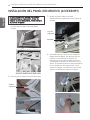
INSTALACIÓN DEL PANEL DECORATIVO (ACCESSORY)
INSTALACIÓN DEL PANEL DECORATIVO (ACCESSORY)
El panel decorativo incluye sus propias
instrucciones de instalación. Antes de
instalar el panel decorativo, retire siempre
la plantilla de papel.
2 Desmonte los cubre-esquinas del panel.
3 Ajuste el panel sobre la unidad
introduciendo los ganchos como ilustra la
imagen.
4 Introduzca dos tornillos en las esquinas
diagonales del panel. No apriete aún los
tornillos. (Los tornillos de fijación se
incluyen en la caja de la unidad interior).
Compruebe la alineación del panel con el
techo. Es posible ajustar la altura mediante
el uso de pernos de suspensión, como
ilustra la imagen. Introduzca los otros dos
tornillos y apriételos todos al máximo.
1 Retire el material de embalaje y desmonte
la rejilla de entrada de aire del panel
frontal.
ESPAÑOL

13
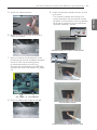
Screw
Instalación del eslabón de la rejilla en el cuerpo del panel
Inserción del borde en el cuerpo del panel
Cierre del pestillo de la puerta
Compruebe las secciones izquierda, derecha y central
CN_VANE 1,2
CN_DISPLAY
ESPAÑOL
INSTALACIÓN DEL PANEL DECORATIVO (ACCESSORY)
5 Ajuste los cubre-esquinas..
6 Retire los dos tornillos de control de la
cubierta del panel.
7 Una un conector de visualización y dos
conectores de control de álabes del panel
frontal a la PCI de la unidad interior.
La marca de posición en la PCI es:
Conector de visualización: CN_DISPLAY
Conector de control de álabes: CN_VANE
1,2
8 Cierre la cubierta de la caja de control.
9 Instale la rejilla de entrada de aire y el filtro
en el panel.
- Tras insertar el borde de la rejilla en el
cuerpo del panel, fije la cuerda al cuerpo
del panel. A continuación, cierre el pestillo
de la puerta y presione en las secciones
izquierda, derecha y central.
ESPAÑOL

14
ESPAÑOL
PRUEBA DE FUNCIONAMIENTO
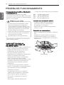
PRECAUCIONES DURANTE LA PRUEBA DE
FUNCIONAMIENTO
- La alimentación eléctrica inicial debe
suministrar como mínimo el 90 % del voltaje
nominal. En caso contrario, el acondicionador
de aire no funcionará.
* Están flojos del tornillos de los terminales?
M4......118 N·cm{12 kgf·cm}
M5......196 N·cm{20 kgf·cm}
M6......245 N·cm{25 kgf·cm}
M8......588 N·cm{60 kgf·cm}
Conexión de la alimentación eléctric
- Conecte el cable de alimentación al
suministro eléctrico independiente
Es necesario un disyuntor.
- Haga funcionar la unidad durante quince
minutos o más.
Evaluación del funcionamiento
- Mida la temperatura de entrada y salida del
aire.
- Asegúrese de que la diferencia entre la
temperatura de entrada y la de salida es
superior a 8 °C (refrigeración) o al contrario
(calefacción).
CUANDO ESTÉ FINALIZADA LA
INSTALACIÓN, COMPRUEBE LOS
SIGUIENTES PUNTOS
- Una vez finalizado el trabajo, asegúrese de
medir y registrar las condiciones de la
prueba de funcionamiento y los datos
almacenados de las mediciones.
- Los elementos de medición son:
temperatura de la habitación, temperatura
exterior, temperatura de succión,
temperatura de soplado, velocidad del
viento, volumen de viento, voltaje,
corriente, presencia de vibraciones y ruidos
anormales, presión de funcionamiento,
temperatura de las tuberías y presión
compresiva.
- En relación con la estructura y aspecto
exterior, compruebe los siguientes puntos.
* La circulación de aire es adecuada?
* El drenaje es suave?
* El aislamiento térmico es completo?
(tuberías del refrigerante y de drenaje)
* Existe alguna fuga de refrigerante?
* Funciona el interruptor del mando a
distancia?
* Existe algún cableado defectuoso?
- Para cancelar la prueba de funcionamiento,
pulse cualquier botón.
PRECAUCIÓN
!
• Para la prueba de funcionamiento, realice
primero una operación de refrigeración,
incluso durante una estación calurosa. Si se
realiza primero una operación de calefacción,
pueden surgir problemas con el compresor.
Se debe prestar mucha atención.
• Realice la prueba de funcionamiento durante
más de 5 minutos sin fallos. (La prueba de
funcionamiento se cancelará
automáticamente 18 minutos después)
Termómetro
PRUEBA DE FUNCIONAMIENTO

INSTRUCCIONES DE INSTALACIÓN
15
ESPAÑOL
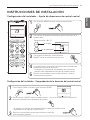
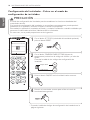
Configuración del instalador - Comprobación de la dirección del control central
(3 s)
˚C / ˚F (5 s)
Con el botón MODE pulsado, pulse el botón Reset.
1
Con el botón de ajuste de temperatura, ajuste la dirección de la
unidad interior.
- Rango de ajuste : 00 ~ FF
2
Tras ajustar la dirección, pulse el botón
ON/OFF hacia la unidad interior una vez.
3
La unidad interior mostrará la dirección seleccionada para
completar el ajuste de dirección.
- El tiempo y el método de visualización de la dirección
pueden variar dependiendo del tipo de unidad interior.
Reinicie el controlador remoto para utilizar el modo de
funcionamiento general.
4
5
N.º de grupo
N.º de unidad interior
Con el botón FUNC. pulsado, pulse el botón RESET.
1
Pulse el botón ON/OFF hacia la unidad interior 1 vez, y la unidad interior mostrará la
dirección ajustada en la ventana de la pantalla.
- El tiempo y el método de visualización de la dirección pueden variar
dependiendo del tipo de unidad interior.
2
Reinicie el controlador remoto para utilizar el modo de
funcionamiento general.
3
INSTRUCCIONES DE INSTALACIÓN
Configuración del instalador - Ajuste de direcciones de control central

Configuración del instalador - Entrar en el modo de
configuración de instalador
PRECAUCIÓN
!
El modo de configuración del instalador permite establecer las funciones detalladas del
controlador remoto.
Si el modo de configuración del instalador no se configura correctamente, puede producir
problemas en el producto, lesiones al usuario o daños a la propiedad.
Este trabajo lo realizará un instalador calificado, y cualquier instalación o cambio realizados por
personas no calificadas eximirán al fabricante de los resultados.
En este caso, no se podrá proporcionar servicio gratuito.
(3 s)
˚C / ˚F (5 s)
Con el botón JET COOL (velocidad del ventilador pulsado),
pulse el botón RESET.
1
Con el botón TEMPERATURE SETTING (ajuste de
temperatura), seleccione el código de función y el valor de
ajuste.
Consulte la tabla de los códigos de configuración de
instalador.
2
Código de función
Código de ajuste
Pulse el botón ON/OFF hacia la unidad interior una vez.
3
Reinicie el controlador remoto para utilizar el modo de
funcionamiento general.
* Consulte la tabla de códigos de configuración de instalador en la
página siguiente.
4
INSTRUCCIONES DE INSTALACIÓN
16
ESPAÑOL

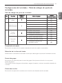
Configuración del instalador - Tabla de códigos de ajuste de
instalador
Tabla de códigos de ajuste de instalador
No. Función
Código de
función
Valor de ajuste
LCD del
controlador remoto
0
Cancelación de
modo
0
0 : Ajusta como principal
00
1 : Ajustar como esclavo
01
1
Selección de la
altura del techo
1
1 : Estándar
11
2 : Bajo
12
3 : Alta
13
4 : Súper alta
14
2
Control
de grupo
2
0 : Ajusta como principal
20
1 : Ajustar como esclavo
21
2 : Comprobar principal/esclavo
22
Calentador
auxiliar
2
3 : Ajuste a calentador auxiliar
23
4 : Cancelar calentador auxiliar
24
5 : Comprobar instalación de
calentador auxiliar
25
Cancelación de modo
Esta función se aplica sólo al modelo de bomba de calor de cambio no automático.
Selección de la altura del techo
Unidad interior conectada al controlador remoto por cable según el ajuste del controlador remoto.
Control de grupo
Esta función se utiliza sólo para el control de grupos. No ajuste esta función si no es para el
control de grupos.
Tras ajustar el control de grupo del producto, apague el aparato y vuelva a encenderlo después de
1 minuto.
Calentador auxiliar
Esta función se aplica sólo a modelos con la función de calentador auxiliar activada.
17
INSTRUCCIONES DE INSTALACIÓN
ESPAÑOL

-
 1
1
-
 2
2
-
 3
3
-
 4
4
-
 5
5
-
 6
6
-
 7
7
-
 8
8
-
 9
9
-
 10
10
-
 11
11
-
 12
12
-
 13
13
-
 14
14
-
 15
15
-
 16
16
-
 17
17
-
 18
18
-
 19
19
-
 20
20
-
 21
21
-
 22
22
-
 23
23
-
 24
24
-
 25
25
-
 26
26
-
 27
27
-
 28
28
-
 29
29
-
 30
30
-
 31
31
-
 32
32
-
 33
33
-
 34
34
-
 35
35
-
 36
36


LG ATNQ30GPLA4 Guía de instalación
- Categoría
- Barbacoas
- Tipo
- Guía de instalación
- Este manual también es adecuado para
en otros idiomas
- English: LG ATNQ30GPLA4 Installation guide
Artículos relacionados
-
LG ATNQ24GNLT0.ANWBLCB Guía de instalación
-
-
-
-
LG AVNQ60GM2A0.ANWTLPS Guía de instalación
-
-
-
-