
P/NO : MFL67791202
INSTALLATION MANUAL
AIR
CONDITIONER
www.lg.com
Please read this installation manual completely before install-
ing the product.
Installation work must be performed in accordance with the
national wiring standards by authorized personnel only.
Please retain this installation manual for future reference
after reading it thoroughly.
Ceiling suspended air conditioner
ESPAÑOL
MFL67791202
ENGLISH

2
TIPS FOR SAVING ENERGY
• Do not cool excessively indoors. This may be harmful for your health and may consume more
electricity.
• Block sunlight with blinds or curtains while you are operating the air conditioner.
• Keep doors or windows closed tightly while you are operating the air conditioner.
• Adjust the direction of the air flow vertically or horizontally to circulate indoor air.
• Speed up the fan to cool or warm indoor air quickly, in a short period of time.
• Open windows regularly for ventilation as the indoor air quality may deteriorate if the air condition-
er is used for many hours.
• Clean the air filter once every 2 weeks. Dust and impurities collected in the air filter may block the
air flow or weaken the cooling / dehumidifying functions.
For your records
Staple your receipt to this page in case you need it to prove the date of purchase or for warranty pur-
poses. Write the model number and the serial number here:
Model number :
Serial number :
You can find them on a label on the side of each unit.
Dealer’s name :
Date of purchase :
Here are some tips that will help you minimize the power consumption when you use the air con-
ditioner. You can use your air conditioner more efficiently by referring to the instructions below:
TIPS FOR SAVING ENERGY
ENGLISH

IMPORTANT SAFETY INSTRUCTIONS
3
ENGLISH
IMPORTANT SAFETY INSTRUCTIONS
READ ALL INSTRUCTIONS BEFORE USING THE APPLIANCE.
Always comply with the following precautions to avoid dangerous situations and ensure peak
performance of your product
WARNING
It can result in serious injury or death when the directions are ignored
CAUTION
It can result in minor injury or product damage when the directions are ignored
WARNING
• Installation or repairs made by unqualified persons can result in hazards to you and others.
• The information contained in the manual is intended for use by a qualified service technician
familiar with safety procedures and equipped with the proper tools and test instruments.
• Failure to carefully read and follow all instructions in this manual can result in equipment mal-
function, property damage, personal injury and/or death.
Installation
• Don’t use a power cord, a plug or a loose socket which is damaged.
- Otherwise, it may cause a fire or electrical shock.
• For electrical work, contact the dealer, seller, a qualified electrician, or an Authorized Service
Center.
- Do not disassemble or repair the product. There is risk of fire or electric shock.
• Always ground the product.
- There is risk of fire or electric shock.
• Install the panel and the cover of control box securely.
- There is risk of fire or electric shock.
• Always install a dedicated circuit and breaker.
- Improper wiring or installation may cause fire or electric shock.
• Use the correctly rated breaker or fuse.
- There is risk of fire or electric shock.
• Do not modify or extend the power cable.
- There is risk of fire or electric shock.
• Do not let the air conditioner run for a long time when the humidity is very high and a door or
a window is left open.
- Moisture may condense and wet or damage furniture.
• Be cautious when unpacking and installing the product.
- Sharp edges could cause injury. Be especially careful of the case edges and the fins on the
condenser and evaporator.
• For installation, always contact the dealer or an Authorized Service Center.
- There is risk of fire, electric shock, explosion, or injury.
!
!
!
ENGLISH

4
IMPORTANT SAFETY INSTRUCTIONS
ENGLISH
• Do not install the product on a defective installation stand.
- It may cause injury, accident, or damage to the product.
• Be sure the installation area does not deteriorate with age.
- If the base collapses, the air conditioner could fall with it, causing property damage, product
failure, and personal injury.
• Do not turn on the breaker or power under condition that front panel, cabinet, top cover, con-
trol box cover are removed or opened.
- Otherwise, it may cause fire, electric shock, explosion or death.
Operation
• Do not store or use flammable gas or combustibles near the product.
- There is risk of fire or failure of product.
CAUTION
Installation
• Always check for gas (refrigerant) leakage after installation or repair of product.
- Low refrigerant levels may cause failure of product.
• Install the drain hose to ensure that water is drained away properly.
- A bad connection may cause water leakage.
• Keep level even when installing the product.
- To avoid vibration or water leakage.
• Do not install the product where the noise or hot air from the outdoor unit could damage the neigh-
borhoods.
- It may cause a problem for your neighbors.
• Use two or more people to lift and transport the product.
- Avoid personal injury.
• Do not install the product where it will be exposed to sea wind (salt spray) directly.
- It may cause corrosion on the product. Corrosion, particularly on the condenser and evaporator
fins, could cause product malfunction or inefficient operation
!
Batteries :
Do not burn, do not try to open it, do not dispose in ordinary trash. Preserve
environment and your health.
After use, batteries must be delivered to the merchant or service authorized
network (Conama number 401 dated 11/2008).
ENGLISH

TABLE OF CONTENTS
5
ENGLISH
2 TIPS FOR SAVING ENER-
GY
3 IMPORTANT SAFETY
INSTRUCTIONS
6 INSTALLATION PLACES
7 THE INDOOR UNIT
INSTALLATION
8 Open side-cover
9 Mounting the anchor nut and bolt
11 Indoor unit drain piping
11 Drain piping
11 Drain test
12 Heat insulation
12 Connecting cables to the indoor unit
12 Wiring connection
14 TEST RUNNING
14 Precautions in test running
14 Check the following items when installa-
tion is complete
14 Connection of power supply
14 Evaluation of the performance
15 Hand over
16 INSTALLATION INSTRUC-
TIONS
16 Installer setting - how to enter installer
setting mode
17 Installer setting - installer setting code
table
17 Installer setting code table
18 Installer setting - setting address of cen-
tral control
18 Installer setting - checking address of
central control
TABLE OF CONTENTS
ENGLISH

6
INSTALLATION PLACES
ENGLISH
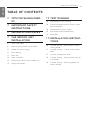
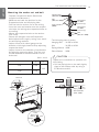
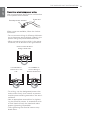
INSTALLATION PLACES
Indoor unit
Ceiling suspended type
- There should not be any heat source or steam near the unit.
- There should not be any obstacles to prevent the air circulation.
- A place where air circulation in the room will be good.
- A place where drainage can be easily obtained.
- A place where noise prevention is taken into consideration.
- Do not install the unit near the door way.
- Ensure the spaces indicated by arrows from the wall, ceiling, or other obstacles.
- The indoor unit must keep the maintenance space.
700(27 – 9/16) or more 700(27 – 9/16) or more
2500 (98 – 3/7)
or more
Floor
10 (13/32)
or more
300 (11 – 13/16)
or more
Unit: mm(inch)
ENGLISH

THE INDOOR UNIT INSTALLATION
7
ENGLISH
THE INDOOR UNIT INSTALLATION
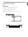
Use the ventilation fan
for smoke-collecting
hood with sufficient
capacity.
Cooking table
Air conditioner
Take enough
distance
• Install the unit horizontally using a level
gauge.
• During the installation, care should be
taken not to damage electric wires.
• Select and mark the position for fixing
bolts and piping hole.
• Decide the position for fixing bolts
slightly tilted to the drain direction after
considering the direction of drain hose.
• Drill the hole for anchor bolt on the ceil-
ing.
CAUTION
!
NOTE
!
• Avoid the following installation location.
1. Such places as restaurants and kitchen
where considerable amount of oil
steam and flour is generated.
These may cause heat exchange effi-
ciency reduction, or water drops, drain
pump mal-function.
In these cases, take the following ac-
tions;
• Make sure that ventilation fan is enough
to cover all noxious gases from this
place.
• Ensure enough distance from the cook-
ing room to install the air conditioner in
such a place where it may not suck oily
steam.
2. Avoid installng air conditioner in such
places where cooking oil or iron pow-
der is generated.
3. Avoid places where inflammable gas is
generated.
4. Avoid place where noxious gas is gen-
erated.
5. Avoid places near high frequency gen-
erators.
ENGLISH

8
THE INDOOR UNIT INSTALLATION
ENGLISH
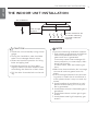
Open side-cover
Step 1
Backside
Right side cover
Backside
Left side
cover
Step 2
Step 5
- Remove two screws from side-cover.
Step 3
S
Step 4
- Remove bracket from side-panel.
- Remove paper bracket from side-cover.
- Unlock side-cover from side-panel slightly
(Tap the side-cover with your palm on the
backside)
- Knock out the pipe hole from the left side-
cover with nipper/plier.
Hold the side-cover with other hand while
tapping to prevent it to fall down.
CAUTION
!
ENGLISH

THE INDOOR UNIT INSTALLATION
9
ENGLISH
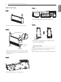
Mounting the anchor nut and bolt
- Prepare 4 suspension bolts. (Each bolts
length should be same.)
- Measure and mark the position for the
Suspension bolts and the piping hole.
- Drill the hole for anchor nut on the ceiling.
- Insert the nuts and washer onto the suspen-
sion bolts for locking the suspension bolts on
the ceiling.
- Mount the suspension bolts to the anchor-
nuts firmly.
- Secure the hangers onto the Suspension
bolts (adjust level roughly.) using nuts, wash-
ers and spring washers.
- Adjust a level with a level gauge on the
direction of left-right, back-forth by adjusting
suspension bolts.
- Adjust a level on the direction of top-bottom
by adjusting supension bolts. Then the unit
will be declined to the bottomside so as to
drain well.
- The following parts is option.
Hanging Bolt - W 3/8 or M10
Nut - W 3/8 or M10
Spring Washer - M10
Plate Washer - M10
(Unit : mm)
Suspension bolt
B
A
Nut
Ceiling
Anchor nut
Washer
Washer
Washer
Suspension
Suspension
bolts
bolts
Suspension
bolts
Spring
washer
Max.
12mm
Nut
Suspension
bolts
Hanger
Washer
Hanging bolt
(W3/8 or M10)
Nut
(W3/8 or M10)
Spring washer
(M10)
Flat washer
for M10
(accessory)
Flat washer
for M10
(accessory)
Nut
(W3/8 or M10)
Wall
Indoor
Outdoor
Slope gradient for
drain Should be
1/50 ~ 1/100
Tighten the nut and bolt to prevent unit
from falling
• Drill the piping hole on the wall slightly
tilted to the outdoor side by using a
Ø 70 hole-core drill.
CAUTION
!
A B
1018
355
1418
VM1
VM2
ENGLISH

10
THE INDOOR UNIT INSTALLATION
ENGLISH
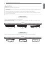
Installation information for declination
- Install declination of the indoor unit is very important for the drain of the convertible type air
conditioner.
- Minimum thickness of the insulation for the connecting pipe shall be 10 mm.
- If the Installation Plates are fixed to horizontal line, the indoor unit after installing will be de-
clined to the bottomside.
CAUTION
!
Front of view
- The unit must be horizontal or inclined at angle.
- The inclination should be less than or equal to 1° or in between 10 to 20 mm inclined in drain
direction as shown in fig.
Ceiling
10~20 mm
Side of view
- The unit must be inclined to the bottomside of the unit when finished installation.
Ceiling
5~10 mm
ENGLISH

THE INDOOR UNIT INSTALLATION
11
ENGLISH
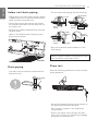
Indoor unit drain piping
- Drain piping must have down-slope (1/50 to
1/100): be sure not to provide up-and-down
slope to prevent reversal flow.
- During drain piping connection, be careful
not to exert extra force on the drain port on
the indoor unit.
- Remove the rubber stopple before connect-
ing drain hose.
- Hook on the bracket after connecting the
drain hose as below.
- Be sure to execute heat insulation on the
drain piping.
Heat insulation material: Polyethylene foam
with thickness more than 8 mm.
Drain piping
- The drain hose should point downward for
easy drain flow.
- Do not make drain piping like the following.
Drain test
Use the following procedure to test the drain
pump operation:
- Set the air direction louvers up-and-down to
the position(horizontally) by hand.
- Pour a glass of water on the evaporator
using a kettle.
- Ensure the water flows through the drain
hose of the indoor unit without any leakage
and goes out the drain exit.
Drain hoseDrain hoseDrain hose
Bracket
Do not raise
Accumulated
drain water
Air
Waving
Water
leakage
Water
leakage
Ditch
Less than
50 mm gap
Water
leakage
Tip of drain
hose dipped
in water
Downward
slope
ENGLISH

12
THE INDOOR UNIT INSTALLATION
ENGLISH
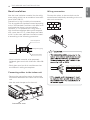
Wiring connection
Connecting cables to the indoor unit
Heat insulation
Use the heat insulation material for the refrig-
erant piping which has an excellent heat-resis-
tance (over 120 °C).
Precautions in high humidity circumstance:
This air conditioner has been tested according
to the "KS Standard Conditions with Mist" and
confirmed that there is not any default.
However, if it is operated for a long time in
high humid atmosphere (dew point tempera-
ture: more than 23 °C), water drops are liable
to fall. In this case, add heat insulation materi-
al according to the following procedure:
- Heat insulation material to be prepared...
Adiabatic glass wool with thickness 10 to 20
mm.
- Stick glass wool on all air conditioners that
are located in ceiling atmosphere.
- Remove the control box cover for electrical
connection between the indoor and out door
unit
- Use the cord clamper to fix the cord.
Connect the wires to the terminals on the
control board individually according to the out-
door unit connection.
Indoor unit
Thermal insulator
Fastening band
Refrigerant piping
Control box cover
1(L) 2(N) 3
1(L) 2(N) 3
The connecting cable
/YL
C
!
Model Phase(Ø) Area(mm
2
)
1 0.75
3 1.00
AVNW36GM1S0
AVNW60LM2S0
NORMAL CROSS-SECTIONAL AREA
ENGLISH

THE INDOOR UNIT INSTALLATION
13
ENGLISH
Precautions when laying power wiring
Use round pressure terminals for connections
to the power terminal block.
When none are available, follow the below
instruction
- Do not connect wiring of different thickness-
es to the power terminal block. (Slack in the
power wiring may cause abnormal heat.)
- When connecting wiring which is the same
thickness, do as shown in the figure below.
- For wiring, use the designated power wire
and connect firmly, then secure to prevent
outside pressure being exerted on the termi-
nal block.
- Use an appropriate screwdriver for tighten-
ing the terminal screws. A screwdriver with
a small head will strip the head and make
proper tighterning impossible.
- Over-tightening the terminal screws may
break them.
Round pressure terminal
Power wire
Connect same thickness
wiring to both sides.
It is forbidden to
connect two to one
side.
It is forbidden to
connect wiring of
different thicknesses.
ENGLISH

14
TEST RUNNING
ENGLISH
Connection of power supply
Check the following items when
installation is complete
Precautions in test running
TEST RUNNING
- The initial power supply must provide at
least 90 % of the rated voltage.
Otherwise, the air conditioner should not be
operated.
Connect the power supply cord to the inde-
pendent power supply.
- Circuit breaker is required.
Operate the unit for 15 minutes or more.
Evaluation of the performance
Measure the temperature of the intake and
discharge air.
Ensure the difference between the intake
temperature and the discharge one is more
than 8 °C (Cooling) or reversely (Heating).
Thermometer
After completing work, be sure to measure
and record trial run properties, and store
measured data, etc.
Measuring items are room temperature, out-
side temperature, suction temperature, blow
out temperature, wind velocity, wind volume,
voltage, current, presence of abnormal vibra-
tion and noise, operating pressure, piping
temperature, compressive pressure.
As to the structure and appearance, check fol-
lowing items.
- Is the circulation of air adequate?
- Is the draining smooth?
- Is the heat insulation completed
(refrigerant and drain piping)?
- Is there any leakage of refrigerant?
- Is the remote controller switch operated?
- Is there any faulty wiring?
- Are not terminal screws loosened?
M4......118 N.cm {12 kgf.cm}
M5......196 N.cm {20 kgf.cm}
M6......245 N.cm {25 kgf.cm}
M8......588 N.cm {60 kgf.cm}
- To cancel the test run, press any button.
• For test run, carry out the cooling oper-
ation firstly even during heating season.
If heating operation is carried out firstly,
it leads to the trouble of compressor.
Then attention must be paid.
• Carry out the test run more than 5 min-
utes without fail.
(Test run will be cancelled 18 minutes
later automatically)
CAUTION
!
ENGLISH

TEST RUNNING
15
ENGLISH
Hand over
Teach the customer the operation and mainte-
nance procedures, using the operation manual
(air filter cleaning, temperature control, etc.).
After the confirmation of the above condi-
tions, prepare the wiring as follows:
• Never fail to have an individual power
specialized for the air conditioner. As
for the method of wiring, be guided by
the circuit diagram pasted on the inside
of control box cover.
• Provide a circuit breaker switch be-
tween power source and the unit.
• The screw which fasten the wiring in
the casing of electrical fittings are liable
to come loose from vibrations to which
the unit is subjected during the course
of transportation. Check them and
make sure that they are all tightly fas-
tened. (If they are loose, it could give
rise to burnout of the wires.)
• Specification of power source.
• Confirm that electrical capacity is suffi-
cient.
• Be sure that the starting voltage is
maintained at more than 90 percent of
the rated voltage marked on the name
plate.
• Confirm that the cable thickness is as
specified in the power sources specifi-
cation.
(Particularly note the relation between
cable length and thickness.)
• Never fail to equip a leakage breaker
where it is wet or moist.
• The following troubles would be caused
by voltage drop-down.
- Vibration of a magnetic switch, dam-
age on the contact point there of, fuse
breaking, disturbance to the normal
function of a overload protection de-
vice.
- Proper starting power is not given to
the compressor.
• Use only 1 remote-controller contained
in indoor unit, when you combine to
use both ceiling suspended type indoor
unit and different Indoor units combina-
tions.
CAUTION
!
ENGLISH

16
INSTALLATION INSTRUCTIONS
ENGLISH
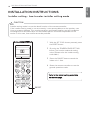
1 With the JET COOL button pressed, press
the RESET button.
2 By using the TEMPERATURE SETTING
button, set function code and setting
value. (Please refer the Intaller setting
code table.)
3 Press the ON/OFF button toward the
indoor unit 1 time.
4 Reset the remote controller to use the
general operation mode.
CAUTION
Installer setting mode is to set the detail function of the remote controller.
If the installer setting mode is not set correctly, it can cause problems to the product, user
injury or property damage. This must be set by an certificated installer, and any installation
or change that is carried out by a non-certificated person should be responsible for the
results. In this case, free service cannot be provided.
!
RESET
R
Refer to the Intaller setting code table
on the next page.
INSTALLATION INSTRUCTIONS
Installer setting - how to enter installer setting mode
ENGLISH

INSTALLATION INSTRUCTIONS
17
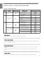
Mode override
This function is only for Non-Auto changeover H/P model.
Ceiling height selection
Indoor unit connected to wired remote controller operate as wired remote controller setting.
only for ceiling cassette type.
Group control (optional)
This function is only for group control. Please don’t set this function in case of non-group
control.
After setting group control of the product, turn off the power then turn it back on after 1
minute.
Auxiliary heater
This function is only applied to models with auxiliary heater function being activated.
No. Function Function code Setting value Remote controller LCD
0 Mode override
0
0 : Set to master
1 : Set to slave
1
Ceiling height
Selection
1
1 : Standard
2 : Low
3 : High
4 : Super high
2
Group control
2
0 : Set to master
1 : Set to slave
2 : Check master/slave
Auxiliary heater
2
3 : Set to auxiliary heater
4 : Cancel auxiliary heater
5 :
Check auxiliary heater Installation
Installer setting code table
Installer setting - installer setting code table
ENGLISH

18
INSTALLATION INSTRUCTIONS
ENGLISH
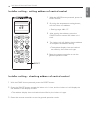
1 With the MODE button pressed, press the
RESET button.
2 By using the temperature setting button,
set the indoor unit address.
• Setting range : 00 ~ FF
3 After setting the address, press the
ON/OFF button toward the indoor unit 1
time.
4 The indoor unit will display the set address
to complete the address setting.
• The address display time and method
can differ by the indoor unit type.
5. Reset the remote controller to use the
general operation mode.
Installer setting - setting address of central control
Installer setting - checking address of central control
1 With the FUNC. button pressed, press the RESET button.
2 Press the ON/OFF button toward the indoor unit 1 time, and the indoor unit will display the
set address in the display window.
• The address display time and method can differ by the indoor unit type.
3 Reset the remote controller to use the general operation mode.
RESET
ENGLISH

MANUAL DE INSTALACIÓN
AIRE
ACONDICIONADO
www.lg.com
Lea completamente este manual de instalación antes de instalar el
producto.
El trabajo de instalación debe realizarse de acuerdo con la Norma-
tiva eléctrica nacional y solamente por personal autorizado.
Por favor, una vez haya leído el manual atentamente, guárdelo para
futuras consultas.
Aire acondicionado de techo
ESPAÑOL

2
CONSEJOS PARA AHORRAR ENERGÍA
ESPAÑOL
CONSEJOS PARA AHORRAR ENERGÍA
• No enfríe excesivamente los espacios. Puede ser nocivo para su salud y consumirá más electrici-
dad.
• Evite el paso de la luz solar con persianas o cortinas cuando esté utilizando el aire acondicionado.
• Mantenga las puertas y ventanas bien cerradas mientras tenga en funcionamiento el aire acondi-
cionado.
• Ajuste la dirección del flujo de aire vertical u horizontalmente para que circule el aire en el interior.
• Aumente la velocidad del ventilador para enfriar o calentar el aire interior con rapidez y en periodo
corto de tiempo.
• Abra las ventanas con regularidad para ventilar, porque la calidad del aire interior puede deteriorar-
se si se utiliza el aire acondicionado durante muchas horas.
• Limpie el filtro del aire cada dos semanas. El polvo y las impurezas recogidas en el filtro de aire
puede bloquear el flujo de aire o debilitar las funciones de refrigeración / deshumidificación.
Como referencia
Grape el justificante de compra en esta página, ya que será su prueba de compra para la garantía.
Escriba aquí el número de modelo y el número de serie:
Número de modelo
Número de serie
Puede encontrarlos en la etiqueta situada en el lateral de cada unidad.
Nombre del distribuidor
Fecha de la compra
Estos consejos le ayudarán a reducir el consumo de energía cuando utilice el aire acondicionado.
Podrá utilizar el aparato de aire acondicionado de forma eficiente siguiendo estas instrucciones:
ESPAÑOL

INSTRUCCIONES DE SEGURIDAD IMPORTANTES
3
ESPAÑOL
INSTRUCCIONES DE SEGURIDAD IMPORTAN-
TES
LEA TODAS LAS INSTRUCCIONES ANTES DE UTILIZAR EL APARATO
Cumpla con las siguientes precauciones para evitar situaciones de peligro y garantizar un funcio-
namiento óptimo de su producto.
ADVERTENCIA
Puede sufrir lesiones de gravedad o mortales si ignora las instrucciones
PRECAUCIÓN
Puede sufrir lesiones leves o dañar el producto si ignora las instrucciones
ADVERTENCIA
• Las instalaciones o reparaciones realizadas por personas no cualificadas pueden dar lugar a
peligros para usted y otras personas.
• La información de este manual está dirigida a personal técnico cualificado, familiarizado con
los procedimientos de seguridad y equipado con las herramientas e instrumentos de prueba
adecuados.
• Lea detenidamente y cumpla con todas las instrucciones de este manual. De lo contrario, el
aparato podría no funcionar correctamente, o producirse lesiones graves o mortales y daños
materiales.
Instalación
• No utilice un cable de alimentación eléctrica, un enchufe o una toma que estén dañados.
- De lo contrario, podría producirse un incendio o descargas eléctricas.
• Para los trabajos eléctricos, póngase en contacto con el distribuidor, el vendedor, un electricis-
ta cualificado o un Servicio técnico autorizado.
- No desmonte ni repare el producto. Existe el riesgo de incendio o descargas eléctricas.
• Conecte el aparato a una toma de tierra.
- Existe el riesgo de incendio o descargas eléctricas.
• Instale el panel y la cubierta de la caja de control con seguridad.
- Existe el riesgo de incendio o descargas eléctricas.
• Instale siempre un circuito y un interruptor específico.
- Un cableado o instalación inadecuados pueden causar incendios o descargas eléctricas
• Utilice un disyuntor o un fusible con la clasificación adecuada.
- Existe el riesgo de incendio o descargas eléctricas.
• No modifique ni alargue el cable de alimentación.
- Existe el riesgo de incendio o descargas eléctricas.
• Evite que el aire acondicionado funcione durante un largo periodo de tiempo cuando la hume-
dad sea alta y se haya dejado abierta una ventana o puerta.
- La humedad puede condensarse y mojar o dañar los muebles.
• Tenga cuidado al desembalar e instalar el producto.
- Los bordes afilados podrían causar heridas. Tenga un cuidado especial con los bordes de la
caja y las aletas del condensador y el evaporador.
!
!
!
ESPAÑOL

4
INSTRUCCIONES DE SEGURIDAD IMPORTANTES
ESPAÑOL
• Para la instalación, retirada o reinstalación, póngase en contacto con el distribuidor o un centro
de servicio técnico autorizado.
- Existe el riesgo de incendio, descargas eléctricas, explosión o heridas.
• No instale el producto en una base de instalación defectuosa.
- Esto podría causar lesiones, accidentes o daños al producto.
• Asegúrese de que el soporte de instalación no se deteriora con el tiempo.
- Si el soporte cae, el aparato de aire acondicionado podría caer con él, causando daños mate-
riales, averías en el aparato, o lesiones personales.
• No encienda el disyuntor ni la alimentación en caso de que el panel frontal, el gabinete, la
cubierta superior o la cubierta de la caja de control se hayan extraído o abierto.
- De lo contrario, podría producirse un incendio, una descarga eléctrica, una explosión o inclu-
so la muerte.
Funcionamiento
• No guarde ni use, ni siquiera permita que haya gas inflamable o combustibles cerca del pro-
ducto.
- Existe riesgo de incendio o averías en el producto.
PRECAUCIÓN
Instalación
• Compruebe que no haya fugas de gas (refrigerante) tras instalar o reparar el producto.
- Unos niveles bajos de refrigerante podrían causar averías en el producto.
• Instale la manguera de drenaje de modo que el agua se vacíe correctamente.
- Una conexión defectuosa podría causar fugas de agua.
• Mantenga el equipo nivelado mientras lo instala.
- Para evitar las vibraciones o fugas de agua.
• No instale el aparato donde el ruido o el aire caliente de la unidad exterior puedan molestar a los
vecinos.
- Podría tener problemas con los vecinos.
• Para mover y transportar el producto son necesarias dos personas.
- Evitará daños personales.
• No instale el producto en un lugar donde pueda estar expuesto al viento marino (viento salado) direc-
tamente.
- Podría causar corrosión en el producto. La corrosión, en particular en las aletas del condensador y
el evaporador, podrían causar averías en el producto o un funcionamiento ineficaz.
!
Baterías :
No las queme ni intente abrirlas, no las elimine con los residuos domésticos.
Proteja el medio ambiente y salud. Una vez agotadas, las se devolverán al
comercio donde se han comprado o un punto de recogida autorizado
(Conama numero 401 de 11/2008).
ESPAÑOL

ÍNDICE
5
ESPAÑOL
2 CONSEJOS PARA AHO-
RRAR ENERGÍA
3 INSTRUCCIONES DE
SEGURIDAD IMPORTAN-
TES
6 LUGARES DE INSTALA-
CIÓN
7 INSTALACIÓN DE LA
UNIDAD INTERIOR
8 Tapa lateral abierta
9 Montaje de la tuerca y tornillo de anclaje
11 Tubo de desagüe de unidad interior
11 Tubería de desagüe
11 Prueba de desagüe
12 Aislamiento del calor
12 Conexión de los cables a la unidad inte-
rior
12 Conexión eléctrica
14 FUNCIONAMIENTO DE
PRUEBA
14 Precauciones durante la prueba de fun-
cionamiento
14 Compruebe lo siguiente cuando haya
finalizado la instalación
14 Conexión de la alimentación eléctrica
14 Evaluación del rendimiento
15 Entrega
16 INSTRUCCIONES DE INS-
TALACIÓN
16 Configuración del instalador - entrar en
el modo de configuración de instalador
17 Configuración del instalador - tabla de
códigos de ajuste de instalador
17 Tabla de códigos de ajuste de instalador
18 Configuración del instalador - ajuste de
direcciones de control central
18 Configuración del instalador - compro-
bación de la dirección del control central
ÍNDICE
ESPAÑOL

6
LUGARES DE INSTALACIÓN
ESPAÑOL
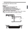
LUGARES DE INSTALACIÓN
700(27 – 9/16) o más 700(27 – 9/16) o más
2500 (98 – 3/7)
o más
Suelo
10 (13/32)
o más
300 (11 – 13/16)
o más
Unidad: mm(inch)
ESPAÑOL

INSTALACIÓN DE LA UNIDAD INTERIOR
7
ESPAÑOL
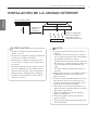
INSTALACIÓN DE LA UNIDAD INTERIOR
Utilice el ventilador
para una campana
extractora con la
capacidad suficiente.
Placa de cocina
Aire acondicionado
Calcule una
distancia
suficiente
• Instale la unidad horizontalmente utili-
zando un nivel.
• Durante la instalación, tenga cuidado de
no dañar los cables eléctricos.
• Seleccione y marque la posición para
los tornillos de fijación y el orificio para
los tubos.
• Decida la posición para la fijación de los
tornillos ligeramente inclinada hacia la
dirección de drenaje, tras considerar la
dirección de la manguera de desagüe.
• Taladre el orificio para el tornillo de an-
claje en el techo.
PRECAUCIÓN
!
NOTA
!
• Evite las siguientes ubicaciones de ins-
talación.
1. Lugares como restaurantes y cocinas
en los que se generen altas cantidades
de vapores de aceite y harina.
Puede reducir la eficiencia del intercam-
bio térmico, o gotas de agua y fallos de
funcionamiento de la bomba de dre-
naje.
En estos casos, proceda del modo si-
guiente:
• Asegúrese de que el ventilador tenga la
capacidad suficiente para todos los
gases nocivos.
• Coloque el aire acondicionado a una dis-
tancia de la cocina que evite que los
humos con aceite se introduzcan en el
aparato de aire acondicionado.
2. No instale el aire acondicionado en lu-
gares donde se genere polvo de aceite
de cocina o de hierro.
3. Evite los lugares donde se generen
gases inflamables.
4. Evite los lugares donde se generen
gases tóxicos.
5. Evite lugares cerca de generadores de
alta frecuencia.
ESPAÑOL

8
INSTALACIÓN DE LA UNIDAD INTERIOR
ESPAÑOL
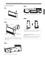
Tapa lateral abierta
Paso 1.
Lado trasero
Lado trasero
Lado trasero
Tapa del
lado izquierdo
P
Paso 2.
- Afloje los dos tornillos de la tapa lateral.
- Separe ligeramente la tapa del panel lateral
Golpee el lado trasero de la tapa con la palma
de la mano
Sujete la tapa con la otra mano al tiempo
que golpea, para evitar que se caiga.
PRECAUCIÓN
!
Paso 3.
- Retire el soporte del panel lateral
P
Paso 5.
P
Paso 4.
- Retire el soporte de papel de la tapa lateral
- Abra el orificio del tubo desde la tapa lateral
izquierda utilizando un alicate o tenaza.
ESPAÑOL

INSTALACIÓN DE LA UNIDAD INTERIOR
9
ESPAÑOL
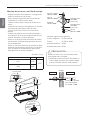
Montaje de la tuerca y tornillo de anclaje
- Prepare 4 tornillos de suspensión. (La longitud de
todos los tornillos será la misma.)
- Mida y marque la posición para los tornillos de
suspensión y el orificio de los tubos
- Taladre el orificio para la tuerca de anclaje en el
techo.
- Introduzca las tuercas y la arandela en los tornillos
de suspensión para fijarlos sobre el techo.
- Fije los tornillos con fuerza en las tuercas de
anclaje.
- Coloque los ganchos en los tornillos de suspen-
sión (ajuste el nivel de forma aproximada) con las
tuercas, arandelas y muelles elásticos.
- Utilice un nivel para nivelar la dirección de izquier-
da a derecha, y adelante-atrás ajustando los torni-
llos de suspensión.
- Ajuste el nivel en la dirección de arriba hacia abajo
ajustando los tornillos de suspensión. A continua-
ción, la unidad se inclinará hacia el lado inferior
para garantizar un correcto desagüe.
- La pieza siguiente es opcional.
Tornillo colgante - W 3/8 o M10
Tuerca - W 3/8 or M10
Arandela elástica - M10
Arandela de placa - M10
(Unidad : mm)
Tornillo de suspensión
B
A
Tuerca
Techo
Tuerca de anclaje
Arandela
Arandela
Tornillo de
Tornillo de
suspensión
suspensión
Tornillo de
suspensión
Arandela
elástica
Máx
12mm
Tuerca
Tornillo de
suspensión
Gancho
Arandela
Tornillo colgante
(W3/8 or M10)
Tuerca
(W3/8 or M10)
Arandela
elástica (M10)
Arandela plana
para M10
(accesorio)
Arandela plana
para M10
(accesorio)
Tuerca
(W3/8 or M10)
Pared
Interior
Exterior
La inclinación del talud
para el drenaje debe
ser de 1/50 ~ 1/100
Apriete la tuerca y el tornillo para evitar
que pueda caer la unidad.
• Utilizando una broca de Ø 70, taladre el
orificio para los tubos en la pared ligera-
mente inclinado hacia el lado exterior.
PRECAUCIÓN
!
A B
1018
355
1418
VM1
VM2
ESPAÑOL

10
INSTALACIÓN DE LA UNIDAD INTERIOR
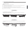
Información de instalación para la inclinación
- La inclinación de la unidad interior es muy importante para el desagüe del aparato de aire
acondicionado de tipo de conducto.
- El grosor mínimo del aislamiento para el tubo de conexión será de 10 mm.
- Si las placas de instalación se fijan en línea horizontal, la unidad interior se inclinará hacia el
lado inferior tras la instalación.
PRECAUCIÓN
!
Vista frontal
- La unidad debe estar horizontal o inclinada.
- La inclinación será inferior o igual a 1° o entre 10 y 20 mm de inclinación en la dirección de
desagüe, como se muestra en la fig.
10~20 mm
Techo
Vista lateral
- La unidad debe quedar inclinada hacia el lado inferior de la unidad cuando se haya finalizado la
instalación.
5~10 mm
Techo
ESPAÑOL

INSTALACIÓN DE LA UNIDAD INTERIOR
11
ESPAÑOL
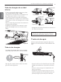
Tubo de desagüe de unidad
interior
- El tubo de desagüe debe tener una inclina-
ción descendente (1/50 a 1/100):
asegúrese de no disponer la inclinación arri-
ba y abajo para evitar un flujo inverso.
- Durante la conexión del tubo de desagüe,
tenga cuidado de no aplicar una fuerza exce-
siva sobre el orificio de desagüe de la unidad
interior.
- Retire el tope de goma antes de conectar la
manguera de desagüe.
- Enganche el soporte tras conectar la man-
guera de desagüe como se muestra más
abajo.
- Asegúrese de colocar aislamiento térmico en
los tubos de desagüe.
Material de aislamiento térmico: espuma
de polietileno de grosor superior a 8 mm.
Tubería de desagüe
- La tubería de drenaje debe estar colocada
hacia abajo para facilitar el flujo de drenaje.
- No haga la conexión de los tubos de desa-
güe del modo siguiente.
Prueba de desagüe
Utilice el procedimiento siguiente para com-
probar el funcionamiento de la bomba de dre-
naje:
- Ajuste las difusor de dirección de aire arriba
y abajo manualmente a la posición (horizon-
tal).
- Vierta un vaso de agua en evaporador utili-
zando una tetera.
- Asegúrese de que el agua fluye por el con-
ducto de drenaje de la unidad de interior sin
que haya fugas y que sale por el drenaje.
MangueraManguera
de desagüede desagüe
Manguera
de desagüe
Soporte
No elevar
Agua de desagüe
acumulada
Aire
Arrugas
Fuga de agua
Fuga de agua
Ditch
Separación
de menos
de 50 mm
Fuga de agua
La punta de la
manguera de
desagüe entra
en el agua
Inclinación
hacia abajo
ESPAÑOL

12
INSTALACIÓN DE LA UNIDAD INTERIOR
ESPAÑOL
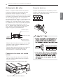
Conexión eléctrica
Conexión de los cables a la unidad
interior
Aislamiento del calor
Utilice un material aislante del calor para el
conducto refrigerante que tenga una gran
resistencia al calor (superior a 120°C).
Precauciones para situaciones del alto nivel de
humedad. Este aparato de aire acondicionado
ha sido evaluado según las “Condiciones
estándar del KS con vapor” y se ha comproba-
do que no presenta ningún defecto. Sin
embargo, si funciona durante mucho tiempo
en ambientes con mucha humedad (tempera-
tura de punto de condensación: más de
23 °C), pueden caer gotas de agua. En este
caso, añada el material aislante del calor
según el siguiente procedimiento:
- Material de aislamiento térmico que se debe
preparar. Lana de vidrio adiabática con un
grosor de 10 a 20mm.
- Pegue todas las lanas de vidrio en todos los
aparatos de aire acondicionado que se
encuentren en un ambiente techado.
- Retire la tapa del caja de control cubierta
para la conexión eléctrica entre la unidad
interior y exterior.
- Utilice la pinza para la fijación del cable.
Conecte individualmente los cables a los ter-
minales de la placa de control, según las cone-
xiones de la unidad de exterior.
Unidad de
interior
Aislante térmico
Banda de fijación
Tubería de refriger
Tapa de caja de control cubierta
1(L) 2(N) 3
1(L) 2(N) 3
/YL
C UCI
!
Modelo Phase(Ø) Area(mm
2
)
1 0,75
3 1,00
AVNW36GM1S0
AVNW60LM2S0
ESPAÑOL

INSTALACIÓN DE LA UNIDAD INTERIOR
13
ESPAÑOL
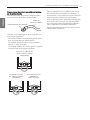
Precauciones durante la conexión del cablea-
do de alimentación
Utilice terminales de presión redondos para
las conexiones al bloque de terminales.
Cuando no se disponga de ellos, siga las ins-
trucciones siguientes.
- No conecte cables de diferente grosor al blo-
que de terminales de alimentación.
Los cables de alimentación flojos pueden
causar un calor anómalo.
- Al conectar cables del mismo grosor, siga las
instrucciones de la figura siguiente.
- Para el cableado, use el cable de alimenta-
ción designado y conéctelo firmemente, a
continuación, fíjelo para evitar que la presión
exterior afecte al bloque de terminales.
- Use un destornillador adecuado para apretar
los tornillos del terminal. Un destornillador
con una punta pequeña dañaría la cabeza y
haría imposible un apretado adecuado.
- Apretar demasiado los tornillos de los termi-
nales podría romperlos.
Terminal de presión redondo
Cable de
corriente eléctrica
Conecte un cableado del
mismo espesor a ambas
extremidades.
Se prohíbe conectar
dos cables a la misma
extremidad.
Se prohíbe conectar
cableados de
diferente espesor.
ESPAÑOL

14
FUNCIONAMIENTO DE PRUEBA
ESPAÑOL
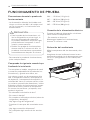
FUNCIONAMIENTO DE PRUEBA
Conexión de la alimentación eléctrica
Compruebe lo siguiente cuando haya
finalizado la instalación
Precauciones durante la prueba de
funcionamiento
- La alimentación eléctrica inicial debe sumi-
nistrar un mínimo del 90 % del voltaje nomi-
nal. De lo contrario, no funcionará el aire
acondicionado.
Conecte el cable de alimentación a la alimen-
tación eléctrica independiente.
- Se necesita un disyuntor.
Mantenga el aparato en funcionamiento
durante 15 minutos o más.
Evaluación del rendimiento
Mida la temperatura del aire de entrada y des-
carga.
Asegúrese de que la diferencia entre la tem-
peratura de entrada y la de descarga sea supe-
rior a 8 ºC (refrigeración) o a la inversa (cale-
facción).
Termómetro
Tras completar el trabajo, asegúrese de medir
y anotar las propiedades de la prueba de fun-
cionamiento, y guarde esos datos, etc.
Los valores a medir son la temperatura de la
sala, la temperatura exterior, la temperatura
de aspiración, la temperatura de expulsión, la
velocidad del viento, el volumen de aire, volta-
je, corriente, presencia de vibraciones y ruidos
anómalos, presión de funcionamiento, tempe-
ratura de los tubos, presión de compresión.
En cuanto a la estructura y el aspecto, com-
pruebe lo siguiente.
- Es adecuada la circulación de aire?
- Es suave el drenaje?
- Es completo el aislamiento térmico (tubos de
refrigerante y desagüe)?
- Hay alguna fuga de refrigerante?
- Funciona el interruptor del controlador remo-
to?
- Hay alguna conexión defectuosa?
- Se ha aflojado algún tornillo de los termina-
les?
M4......118 N.cm {12 kgf.cm}
M5......196 N.cm {20 kgf.cm}
M6......245 N.cm {25 kgf.cm}
M8......588 N.cm {60 kgf.cm}
- Para cancelar la prueba de funcionamiento,
pulse cualquier botón.
• Para la prueba de funcionamiento, uti-
lice la refrigeración en primer lugar, in-
cluso en temporada de calefacción.
Si prueba la calefacción en primer lugar,
puede dañarse el compresor. A conti-
nuación, preste atención.
• Realice una prueba de funcionamiento
durante más de 5 minutos sin fallo. La
prueba de funcionamiento se cancelará
automáticamente después 18 minutos
PRECAUCIÓN
!
ESPAÑOL

FUNCIONAMIENTO DE PRUEBA
15
ESPAÑOL
ENTREGA
Enseñe al cliente los procedimientos de uso y
mantenimiento, ayudándose del manual de
instrucciones (limpieza del fitro de aire, control
de temperatura, etc.).
Tras la confirmación de estas condicio-
nes, prepare el cableado del modo si-
guiente.
• No olvide que debe disponerse un cir-
cuito de alimentación eléctrica indivi-
dual para el aparato de aire
acondicionado. Como método de cable-
ado, guíese por el diagrama del circuito
que se encuentra en el interior de la cu-
bierta de control.
• Disponga un disyuntor entre la alimen-
tación eléctrica y la unidad.
• Los tornillos que fijan el cableado en la
caja de conexiones eléctricas puede
aflojarse con las vibraciones durante el
transporte.
Compruébelos y asegúrese de que
están firmemente apretados. Si están
sueltos, podrían quemarse los cables.
• Especificación de la fuente de alimenta-
ción.
• Confirme que la capacidad eléctrica es
suficiente.
• Asegúrese de que se mantiene la ten-
sión inicial a más de un 90% de la ten-
sión nominal marcada en la placa de
identificación.
• Confirme que el grosor del cable es tal
y como se indica en las especificacio-
nes de fuente de alimentación.
En particular, tenga en cuenta la rela-
ción entre la longitud y el grosor del
cable.
• No olvide colocar un disyuntor de fugas
donde haya agua o humedad.
• Las causas siguientes podrían causar
una caída de voltaje.
- Las vibraciones del interruptor magné-
tico, daños en el punto de contacto,
rotura del fusible y alteración de la
función normal del dispositivo de pro-
tección contra sobrecargas.
- Energía inadecuada suministrada al
compresor.
• Utilice sólo el controlador remoto in-
cluido con la unidad interior, cuando
combine la utilización de la unidad inte-
rior de tipo de techo suspendido y dife-
rentes combinaciones de unidades
interiores, como se muestra más ade-
lante.
PRECAUCIÓN
!
ESPAÑOL

16
INSTALLATION INSTRUCTIONS
ESPAÑOL
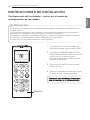
1 Con el botón JET COOL (velocidad del
ventilador pulsado), pulse el botón RESET.
2 Con el botón TEMPERATURE SETTING
(ajuste de temperatura), seleccione el códi-
go de función y el valor de ajuste.
Consulte la tabla de los códigos de confi-
guración de instalador.
3 Pulse el botón ON/OFF hacia la unidad
interior una vez.
4 Reinicie el controlador remoto para utilizar
el modo de funcionamiento general.
PRECAUCIÓN
El modo de configuración del instalador permite establecer las funciones detalladas del con-
trolador remoto.
Si el modo de configuración del instalador no se configura correctamente, puede producir
problemas en el producto, lesiones al usuario o daños a la propiedad.
Este trabajo lo realizará un instalador cualificado, y cualquier instalación o cambio realizados
por personas no cualificadas eximirán al fabricante de los resultados.
En este caso, no se podrá proporcionar servicio gratuito.
!
REINICIO
C
Consulte la tabla de códigos de configura-
ción de instalador en la página siguiente.
INSTRUCCIONES DE INSTALACIÓN
Configuración del instalador - entrar en el modo de
configuración de instalador
ESPAÑOL

INSTALLATION INSTRUCTIONS
17
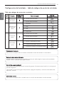
Cancelación de modo
Esta función se aplica sólo al modelo de bomba de calor de cambio no automático.
Selección de la altura del techo
Unidad interior conectada al controlador remoto por cable según el ajuste del controlador
remoto. Sólo al cassette de acople al techo
Control de grupo (opcional)
Esta función se utiliza sólo para el control de grupos. No ajuste esta función si no es para el
control de grupos.
Tras ajustar el control de grupo del producto, apague el aparato y vuelva a encenderlo des-
pués de 1 minuto.
Calentador auxiliar
Esta función se aplica sólo a modelos con la función de calentador auxiliar activada.
Nº Función
Código de
función
Valor de ajuste
LCD del
controlador remoto
0
Cancelación
de modo
0
0 : Ajusta como principal
1 : Ajustar como esclavo
1
Selección de
la altura del
techo
1
1 : Estándar
2 : Bajo
3 : Alta
4 : Súper alta
2
Control de
grupo
2
0 : Ajusta como principal
1 : Ajustar como esclavo
2 : Comprobar principal/esclavo
Calentador
auxiliar
2
3 : Ajuste a calentador auxiliar
4 : Cancelar calentador auxiliar
5 :
Comprobar instalación de calentador auxiliar
Tabla de códigos de ajuste de instalador
Configuración del instalador - tabla de códigos de ajuste de instalador
ESPAÑOL

18
INSTALLATION INSTRUCTIONS
ESPAÑOL
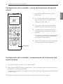
1 Con el botón MODE pulsado, pulse el
botón Reset.
2 Con el botón de ajuste de temperatura,
ajuste la dirección de la unidad interior.
• Rango de ajuste : 00 ~ FF
3 Tras ajustar la dirección, pulse el botón
ON/OFF hacia la unidad interior una vez.
4 La unidad interior mostrará la dirección
seleccionada para completar el ajuste de
dirección.
• El tiempo y el método de visualización de
la dirección pueden variar dependiendo
del tipo de unidad interior.
5 Reinicie el controlador remoto para utilizar
el modo de funcionamiento general.
Configuración del instalador - ajuste de direcciones de control
central
Configuración del instalador - comprobación de la dirección del
control central
1 Con el botón FUNC. pulsado, pulse el botón RESET.
2 Pulse el botón ON/OFF hacia la unidad interior 1 vez, y la unidad interior mostrará la dirección
ajustada en la ventana de la pantalla.
• El tiempo y el método de visualización de la dirección pueden variar dependiendo del tipo de
unidad interior.
3 Reinicie el controlador remoto para utilizar el modo de funcionamiento general.
REINICIO
ESPAÑOL

-
 1
1
-
 2
2
-
 3
3
-
 4
4
-
 5
5
-
 6
6
-
 7
7
-
 8
8
-
 9
9
-
 10
10
-
 11
11
-
 12
12
-
 13
13
-
 14
14
-
 15
15
-
 16
16
-
 17
17
-
 18
18
-
 19
19
-
 20
20
-
 21
21
-
 22
22
-
 23
23
-
 24
24
-
 25
25
-
 26
26
-
 27
27
-
 28
28
-
 29
29
-
 30
30
-
 31
31
-
 32
32
-
 33
33
-
 34
34
-
 35
35
-
 36
36
-
 37
37


LG AVNW36GM1S0.ANWTLAR Guía de instalación
- Tipo
- Guía de instalación
- Este manual también es adecuado para
En otros idiomas
Documentos relacionados
-
LG AVNQ60GM2A0.ANWTLAT Guía de instalación
-
LG AVNQ60GM2A0.ANWTLPS Guía de instalación
-
-
-
-
-
LG CV18.NJ2R0 Manual de usuario
-
LG UV36H.NL1 Manual de usuario
-
LG UV42.NLD Manual de usuario
-
LG ATNQ30GPLA4 Guía de instalación