Alpine RSE-K100TN El manual del propietario
- Categoría
- Cofres de almacenamiento
- Tipo
- El manual del propietario
La página se está cargando...

1)
2)
4)
3)
5A
10A
5) 6) 7) 8)
12)
10)9)
D
D
GB
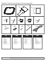
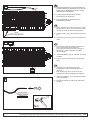
Pos. Bezeichnung Anzahl
1. Rahmen 1x
2. Halterung 1x
3. Schnittschablone 1x
4. Schraube 4,2x16 2x
5. Niete 4,0x21,3 2x
6. Sicherung 5A 1x
7. Sicherung 10A 1x
8. Crimpflachstecker 2x
9. Ringkabelschuh 1x
10. Parallelverbinder 1x
11. Quetschverbinder 4x
12. Kabelbinder 5x
13. Kabelbaum (Verlängerung) 1x
Item Description Quantity
1. Frame 1x
2. Mount 1x
3. Cutting template 1x
4. Screw 4,2x16 2x
5. Rivet 4,0x21,3 2x
6. Fuse 5A 1x
7. Fuse 10A 1x
8. Crimp flat connection 2x
9. Ring connector 1x
10. Quick slide connector 1x
11. Butt connector 4x
12. Cable tie 5x
13. Harness (extension) 1x
11)
Stückliste / Parts list/ Liste de pièces/ Lista de componentes
13)
FR
Item Description Quantité
1. Garniture 1x
2. Entretoise 1x
3. Gabarit de découpage 1x
4. Vis 4,2x16 2x
5. Rivet 4,0x21,3 2x
6. Fusible 5A 1x
7. Fusible 10A 1x
8. Cosse plate 2x
9. Cosse annulaire 1x
10. Clip rapide 1x
11. Cosse 4x
12. Collier 5x
13. Faisceau (extension) 1x
Copyright MS Design - Autotuning GmbH
C
2/12
ES
Item Descripción Cantidad
1. Marco 1x
2. Soporte 1x
3. Plantilla 1x
4. Tornillo 4,2x16 2x
5. Remache 4,0x21,3 2x
6. Fusible 5A 1x
7. Fusible 10A 1x
8. Conector plano de presión 2x
9. Terminal de anilla 1x
10. Conector rápido de presión 1x
11. Conector de empalme 4x
12. Brida de plá stico 5x
13. Cableado (prolongación) 1x
Montageanleitung/ Mounting instructions/ Instructions de montage/ Instrucciones de montaje

a)
b)
D
D
GB
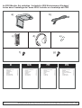
Pos. Bezeichnung Anzahl
a) DVD-Deckenmonitor 1x
b) Kabelbaum 1x
c) Fernbedienung 1x
d) Kopfhörer 1x
e) Batterien 4x
f) Schraube TB 3x8 6x
g) Schraube CM 4x8 4x
Item Description Quantity
a) DVD Overhead Monitor 1x
b) Harness 1x
c) Remote Control 1x
d) Headphone 1x
e) Batteries 4x
f) Screw TB 3x8 6x
g) Screw CM 4x8 4x
Im PKG Monitor Set enthalten / Included in PKG Entertainment Package/
d)
e)
f)
g)
c)
Inclus dans l'emballage de l'écran PKG/ Incluido en el embalaje del PKG
FR
Item Description Quantité
a) Moniteur DVD plafonnier 1x
b) Faisceau 1x
c) Télécommande 1x
d) Casque 1x
e) Piles 4x
f) Vis TB 3x8 6x
g) Vis CM 4x8 4x
Copyright MS Design - Autotuning GmbH
C
3/12
ES
Item Descripción Cantidad
a) Monitor de techo DVD 1x
b) Cableado 1x
c) Mando a distancia 1x
d) Auriculares inalámbricos 1x
e) Pilas 4x
f) Tornillo TB 3x8 6x
g) Tornillo CM 4x8 4x
Montageanleitung/ Mounting instructions/ Instructions de montage/ Instrucciones de montaje

5mm
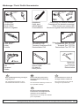
Werkzeuge / Tools/ Outils/ Herramientas
Crimpzange/
Crimping tool/
Pince à sertir/
Alicate de engastar
Kreppband/
Crepe tape/
Adhésif papier/
Cinta adhesiva
Bohrmaschine/
Drill/
Perceuse/
Taladro
Cutter-messer/
Cutter knife/
Cutter/
Cuchilla
Schraubendreher torx T27;T30/
Screwdrivers torx T27;T30/
Tournevis Torx T27;T30/
Destornillado Torx T27;T30
Schraubendreher PH2/
Screwdriver PH2/
Tournevis Cruciforme PH2/
Destornillador PH2
Schraubenschlüssel SW8/
Wrench WS8/
Clé plate 8/
Llave ja de 8
Crimpzange für isolierte verbinder/
Crimping tool for isolated connectors/
Pince à sertir pour cosses ISO/
Alicate de engastar terminales aislados
iso
Nietzange/
Rivet gun/
Pince à rivets/
Remachadora
Copyright MS Design - Autotuning GmbH
C
4/12
D GB F
Bitte die Montageanleitung vor Beginn
sorgfältig lesen.
Wir empfehlen die Montage in einer
Fachwerkstatt durchführen zu lassen.
Please read fitting instructions
thoroughly before commencing
installation.
We recommend that fitting is carried out
by a specialist workshop.
Lire attentivement la notice de
montage avant de commencer.
Nous recommandons de confier le
montage à un professionnel.
ES
Por favor lea minuciosamente las
instrucciones de montaje antes de
comenzar con la instalación.
Sugerimos que el montaje sea realizado
por un especialista.
Montageanleitung/ Mounting instructions/ Instructions de montage/ Instrucciones de montaje

2
D
GB
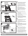
1. Die mitgelieferte Schablone (3) ausschneiden,
am Himmel positionieren und mit Kreppband
fixieren. Nach dem Fixieren nochmals
nachmessen, ob die Schablone mittig sitzt.
2. Wie im Bild gezeigt, den inneren Bereich mit
einem geeigneten Messer ausschneiden.
Darauf achten, dass die Dachhaut oder am
Himmel angeklebte Leitungen nicht beschädigt
werden.
3. Obere Konsole ausbauen
Zuerst die vordere Innenraumleuchten-
abdeckung ausclipsen, die beiden Torx-
Schrauben entfernen und die Lampeneinheit
herausnehmen. Anschließend alle Fächer der
Konsole öffnen und die 6 Torxschrauben
entfernen.
Die Konsole kann jetzt ausgebaut werden.
1
3
1. Cut out the provided template (3). Fix the
template with crepe tape. After that check the
right position again.
2. As shown in the picture, cut out the inner area
with a suitable knife.
Be careful not to damage the roofing or the cable
affixed in the roof's interior.
3. Dismounting the upper console
At first unclip the front covering of the interior
lamp. Remove both torx screws and dismantle
the interior lamp. Open all compartments and
remove the remaining 6 torx screws. After that,
the console can be removed.
FR
1. Caler le gabarit de découpage (3). Le fixer à
l'aide de l'adhésif dans le but de vérifier le bon
positionnement de celui-ci.
2. Comme indiqué dans le schéma découper
délicatement la garniture du toit, attention à ne
pas endommager d'éventuels câbles ou autres
composants.
3. Démontage de la console
En premier lieu dé-clipper le capot de la lampe
intérieure. Retirer les deux vis torx puis démonter
le plafonnier. Ouvrir tous les compartiments puis
retirer les 6 autres vis torx. Après cela toute la
console peut être retirée.
Copyright MS Design - Autotuning GmbH
C
5/12
ES
1. Cortar la plantilla suministrada (3). Fijar la
plantilla con la cinta adhesiva. Después de ello,
comprobar nuevamente la correcta posición.
2. Como indica la gura, cortar el área interior
con una cuchilla. Tener cuidado de no dañar
El techo o los cables jados en su interior.
3. Desmontar la consola superior. En primer lugar
retirar la tapa frontal de la lámpara interio. Soltar
ámbos tornillos torx y desmonte la lámpara
interior. Abra todos los compartimentos y suelte
los 6 tornillos torx restantes.
Después de ello, la consola puede ser retirada.
Montageanleitung/ Mounting instructions/ Instructions de montage/ Instrucciones de montaje

5
6
D
GB
4
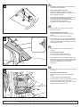
4. Die beiden Torx-Schrauben in der Verstärkung
unter der Konsole entfernen.
5.
Den kleinen Deckel ausclipsen und die
Schrauben dahinter entfernen. Die Abdeckung
kann ausgeclipst werden.
6. Zuerst die seitliche Abdeckung ausclipsen und
den Deckel des Ablagefachs entfernen.
Die im Bild gezeigten Schrauben entfernen und
die große Abdeckung abnehmen.
Die Stecker am Lichtschalter entriegeln.
Abdeckung A-Säule ausbauen
4. Remove both torx-screws from the bracing
behind the console.
5.
Unclip the small cap and remove the screw
behind.
The covering of A-pillar can be uncliped.
6. At first unclip the side cover and dismantle the
cover of the lower console. Remove the screws
shown in the illustration and dismount the panel.
Unplug the light switch.
Dismounting A-pillar covering
FR
4. Retirer les deux vis torx situées derrière la
console.
5.
Retirer le cache puis dévisser la vis.
Le montant peut ensuite être dé-clippé.
6. En premier lieu, retirer le panneau latéral, puis
démonter de couvercle de la partie inférieure de
la console. Retirer les vis comme indiqué dans
l'illustration et débrancher le connecteur
d'éclairage.
Démontage du montant.
Copyright MS Design - Autotuning GmbH
C
6/12
ES
4. Soltar los dos tornillos torx del refuerzo detrás de
la consola.
5.
Retirar un pequeño tapón y soltar el tornillo
oculto.
La tapa del pilar-A puede desgraparse.
6. En primer lugar desgrape la tapa lateral y la tapa
de la consola inferior. Retire los tornillos
mostrados en la ilustración y desmonte el panel.
Desconecte el interruptor de luz.
Desmontar la tapa del pilar-A.
Montageanleitung/ Mounting instructions/ Instructions de montage/ Instrucciones de montaje

door/ green
Tür/ grün
puerta/ verde
porte/ vert
9
D
GB
7
1
2
3
44
3
1
2
1: Gelb/ yellow/ jaune/ amarillo
2: Rot/ red/ rouge/ rojo
3: Schwarz/ black/ noir/ negro
4: Grün/ green/ vert/ verde
iso
8
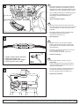
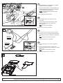
7. Den Sicherungskasten durch lösen der beiden
Schrauben abnehmen. Die Abdeckung auf der
Rückseite des Sicherungskastens entfernen. Die
Abdeckung ist an den gezeigten Stellen arretiert.
8. Den im PKG-Set enthaltenen Kabelbaum (b) mit
der mitgelieferten Verlängerung (13) unter
Verwendung der Quetschverbinder (11)
verlängern.
9. Übersicht Kabelverlegung.
7. Loosen the both screws and remove the fuse
box. After that, remove the cover on the back side
of the fuse holder. It is locked as shown in the
illustration.
8. Extend the harness (b) from the PKG-kit with
the supplied extension-harness (13).
Use the butt connectors (11).
9. Wiring diagram.
FR
7. Dévisser les deux vis puis retirer la boîte à
fusibles. Ensuite retirer le capot à l'arrière du
porte fusibles. Il est verrouillé comme indiqué
dans l'illustration.
8. Procéder à l'extension du faisceau (b) du PKG
avec le faisceau fourni (13).
Pour cela utiliser les cosses à sertir (11).
9. Schéma de câblage.
Copyright MS Design - Autotuning GmbH
C
7/12
ES
7. Aojar ámbos tornillos y retirar la caja de
portafusibles.
Luego, retirar la tapa de la parte trasera de la
caja porta-fusibles. Está bloqueada según se
muestra en la ilustración.
8. Prolongue el cableado (b) del kit del PKG con
los cables de extensión suministrados (13).
Use los terminales tubo de empalme (11).
9. Diagrama de cableado.
Montageanleitung/ Mounting instructions/ Instructions de montage/ Instrucciones de montaje

D
GB
11
10
BATT
ACC
rot/ red/ rouge/ rojo
gelb/ yellow/ jaune/ amarillo
12
D
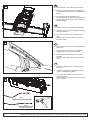
10. Den Kabelbaum wie im Bild gezeigt verlegen.
11. Das Kabel entlang des Original-Kabelbaums
in der A-Säule weiterführen und mit Kabelbindern
fixieren.
12. Die violetten Arretierungsschienen am
Sicherungskasten ein Stück nach außen ziehen.
Die Crimpflachstecker (8) am roten und gelben
Kabel anbringen.
10. Install the harness as shown in the illustration.
11. Install the harness along the original wiring and
fix it with cable ties.
12. From the fuse box pull out the purple locking
pegs.
Crimp the flat connectors (8) on the red and
the yellow cable.
FR
10. Faire cheminer le faisceau comme indiqué dans
l'illustration.
11. Faire passer le faisceau le long du câblage
d'origine puis le fixer à l'aide de colliers.
12. Tirer les pattes violettes situées sur la boîte
à fusibles.
Sertir les cosses plates (8) sur les fils jaune et
rouge.
Copyright MS Design - Autotuning GmbH
C
8/12
ES
10. Instalar el cableado como se muestra en la
illustración.
11. Instalar el cableado junto al cableado original
y jarlo con las bridas de plástico.
12. En la caja porta-fusibles, tirar de los clips de
bloqueo púrpuras.
Colocar los terminales planos (8) en los cables
Rojo y amarillo.
Montageanleitung/ Mounting instructions/ Instructions de montage/ Instrucciones de montaje

GB
55
25
BATT
55
25
ACC
Rot/ red/ rouge/ rojo
gelb/ yellow/jaune/ amarillo
13
25
55
10A
5A
25
55
14
ground/ black
Masse/ schwarz
iso
masse/ noir
masa/ negro
15
DD
13. Das gelbe Kabel (BATT) auf der Rückseite des
Sicherungskastens in Steckplatz 55 und das rote
Kabel (ACC) in Steckplatz 25 stecken und die
Arretierungen hineindrücken.
14. Auf der Vorderseite die entsprechenden
Sicherungen (7,8) einstecken.
15. Den Ringkabelschuh (9) am schwarzen
Massekabel aufcrimpen.
13. At the rearside of the fuse box plug in the yellow
(BATT) cable in slot 55. For the red (ACC) cable
use slot 25 and push back the locking device.
14. Insert the fuses (7,8) at the front side of the fuse
box.
15. Crimp the ring connector (9) to the black ground
cable.
FR
13. A l'arrière de la boîte à fusibles connecter le fil
jaune (+Permanent) dans l'alvéole 55.
Le fil rouge (Accessoire) doit être connecté à
l'alvéole 25 , ensuite repousser le système
de verrouillage.
14. Insérer les fusibles (7,8) sur le devant de la boîte
à fusibles.
15. Sertir la cosse circulaire (9) sur le fil de masse
(noir).
Copyright MS Design - Autotuning GmbH
C
9/12
ES
13. Conectar en la parte trasera de la caja
portafusibles el cable amarillo (BATT) en la
ranura 55.
Para el cable rojo (ACC) use la ranura 25 y
presione hacia atrás el dispositivo de bloqueo.
14. Inserte los fusibles (7, 8) en la parte frontal de la
caja porta-fusibles.
15. Engaste el terminal de anilla (9) al cable negro
de masa.
Montageanleitung/ Mounting instructions/ Instructions de montage/ Instrucciones de montaje

D
GB
ground
Masse
masa
16
blue/ grey
blau/ grau
door/ green
Tür/ grün
bleu/ gris
porte/ vert
Azul/ gris
puerta/ verde
17
18
16. Das Massekabel, wie dargestellt am originalen
Masseanschluss verschrauben.
17. Das grüne Kabel mittels Parallelverbinder (10)
mit dem blau/grauen Kabel der serienmäßigen
Innenraumbeleuchtung verbinden.
: Es wird empfohlen die Kabel durch
Löten zu verbinden.
18. Die Halterung (2) positionieren.
Hinweis
16. Fix the black cable to the original ground
connection.
17. Connect the green and the blue/grey cable
from the interior light using a quick slide
connector (10).
We recommend soldering.
18. Place the mount (2) in position.
Note:
FR
16. Fixer le fil noir sur le point de masse d'origine.
17. Brancher le fil vert au fil bleu/gris d'alimentation
de l'éclairage intérieur en utilisant un clip rapide
(10).
Nous recommandons de souder.
18. Placer l'entretoise (2) en position.
Note:
Copyright MS Design - Autotuning GmbH
C
10/12
ES
16. Fije el cable negro a la conexión original de
masa.
17. Conecte los cables verde y azul/gris de la
almentación de la luz interior usando un conector
rápido (10).
Nosotros recomendamos soldar.
18. Colocar el soporte (2) en su posición.
Nota:
Montageanleitung/ Mounting instructions/ Instructions de montage/ Instrucciones de montaje

D
GB
4,2x16
5mm
15mm
2Nm
19
20
1,5Nm
TB 3x8
21
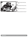
19. Die Halterung (2) an den serienmäßigen
Befestigungspunkten der Konsolenverstärkung
mit den beiliegenden Schrauben (4) fixieren.
An den beiden hinteren Löchern durch die
Halterung in die Dachverstrebung bohren
(max 15mm!) und mit den mitgelieferten Nieten
(5) befestigen.
20. Den Deckenmonitor (a) im Rahmen (1)
platzieren.
21. Den Rahmen mit dem Monitor verschrauben.
Verwenden Sie hierfür die im PKG-Set
enthaltenen Schrauben (f).
19. Fix the mount (2) at the original fixing points with
the provided screws (4).
Drill through the back holes into the roof beam
(max 15mm). Fix the mount with the provided
rivets (5).
20. Place the overhead monitor (a) in the frame (1).
21. Fix the frame with the monitor. Use the screws (f)
supplied in the PKG-kit.
FR
19. Fixer l'entretoise (2) à l'emplacement d'origine à
l'aide des vis fournies (4).
Percer à travers les trous situés à l'arrière dans
l'arceau de toit (prof. max:15mm). Fixer
l'entretoise à l'aide des rivets (5) fournis.
20. Placer l'écran (a) dans la garniture (1).
21. Fixer la garniture à l'écran. Utiliser les vis (f)
fournies avec le PKG.
Copyright MS Design - Autotuning GmbH
C
11/12
ES
19. Fije el marco (2) en los puntos originales de
montaje con los tornillos suministrados (4).
Taladre el arco del techo a través de los
agujeros (máx 15mm). Fije el soporte con los
remaches suministrados (5).
20. Coloque el monitor de techo (a) en el marco (1).
21. Fije el marco con el monitor. Utilice los tornillos (f)
suministrados en el kit del PKG.
Montageanleitung/ Mounting instructions/ Instructions de montage/ Instrucciones de montaje

D
GB
2,5Nm
CM 4x8
22
22. Den Stecker anschließen und Monitor mit den
Schrauben (g) vom PKG-Set an der Halterung
befestigen.
22. Plug in the connector and fix the monitor to the
mount while using the screws (g) from the PKG-
kit.
FR
22. Brancher le connecteur puis fixer l'écran à
l'entretoise en utilisant les vis (g) fournies avec le
PKG.
Copyright MS Design - Autotuning GmbH
C
12/12
ES
22. Inserte el conector y fije el monitor al soporte con
los tornillos (g) suministrados en el kit del PKG.
Montageanleitung/ Mounting instructions/ Instructions de montage/ Instrucciones de montaje
Transcripción de documentos
Stückliste / Parts list/ Liste de pièces/ Lista de componentes 2) 1) 4) 5) 9) 7) 5A GB Pos. Bezeichnung 1. 2. 3. 4. 5. 6. 7. 8. 9. 10. 11. 12. 13. Rahmen Halterung Schnittschablone Schraube 4,2x16 Niete 4,0x21,3 Sicherung 5A Sicherung 10A Crimpflachstecker Ringkabelschuh Parallelverbinder Quetschverbinder Kabelbinder Kabelbaum (Verlängerung) Anzahl Copyright MS Design - Autotuning GmbH 1x 1x 1x 2x 2x 1x 1x 2x 1x 1x 4x 5x 1x Item Description 1. 2. 3. 4. 5. 6. 7. 8. 9. 10. 11. 12. 13. Frame Mount Cutting template Screw 4,2x16 Rivet 4,0x21,3 Fuse 5A Fuse 10A Crimp flat connection Ring connector Quick slide connector Butt connector Cable tie Harness (extension) 8) 10A 12) 11) 10) DD C 6) 3) 13) FR Quantity 1x 1x 1x 2x 2x 1x 1x 2x 1x 1x 4x 5x 1x Item Description 1. 2. 3. 4. 5. 6. 7. 8. 9. 10. 11. 12. 13. Garniture Entretoise Gabarit de découpage Vis 4,2x16 Rivet 4,0x21,3 Fusible 5A Fusible 10A Cosse plate Cosse annulaire Clip rapide Cosse Collier Faisceau (extension) ES Quantité 1x 1x 1x 2x 2x 1x 1x 2x 1x 1x 4x 5x 1x Item Descripción 1. 2. 3. 4. 5. 6. 7. 8. 9. 10. 11. 12. 13. Marco Soporte Plantilla Tornillo 4,2x16 Remache 4,0x21,3 Fusible 5A Fusible 10A Conector plano de presión Terminal de anilla Conector rápido de presión Conector de empalme Brida de plá stico Cableado (prolongación) Cantidad 1x 1x 1x 2x 2x 1x 1x 2x 1x 1x 4x 5x 1x Montageanleitung/ Mounting instructions/ Instructions de montage/ Instrucciones de montaje 2/12 Im PKG Monitor Set enthalten / Included in PKG Entertainment Package/ Inclus dans l'emballage de l'écran PKG/ Incluido en el embalaje del PKG b) a) d) c) e) g) f) DD Pos. Bezeichnung a) b) c) d) e) f) g) DVD-Deckenmonitor Kabelbaum Fernbedienung Kopfhörer Batterien Schraube TB 3x8 Schraube CM 4x8 C FR GB Anzahl Copyright MS Design - Autotuning GmbH 1x 1x 1x 1x 4x 6x 4x Item Description a) b) c) d) e) f) g) DVD Overhead Monitor Harness Remote Control Headphone Batteries Screw TB 3x8 Screw CM 4x8 Quantity 1x 1x 1x 1x 4x 6x 4x ES Item Description a) b) c) d) e) f) g) Moniteur DVD plafonnier Faisceau Télécommande Casque Piles Vis TB 3x8 Vis CM 4x8 Quantité 1x 1x 1x 1x 4x 6x 4x Item Descripción a) b) c) d) e) f) g) Monitor de techo DVD Cableado Mando a distancia Auriculares inalámbricos Pilas Tornillo TB 3x8 Tornillo CM 4x8 Cantidad 1x 1x 1x 1x 4x 6x 4x Montageanleitung/ Mounting instructions/ Instructions de montage/ Instrucciones de montaje 3/12 Werkzeuge / Tools/ Outils/ Herramientas iso Crimpzange/ Crimping tool/ Pince à sertir/ Alicate de engastar Kreppband/ Crepe tape/ Adhésif papier/ Cinta adhesiva Cutter-messer/ Cutter knife/ Cutter/ Cuchilla Schraubendreher PH2/ Schraubendreher torx T27;T30/ Screwdriver PH2/ Screwdrivers torx T27;T30/ Tournevis Cruciforme PH2/ Tournevis Torx T27;T30/ Destornillador PH2 Destornillado Torx T27;T30 Crimpzange für isolierte verbinder/ Crimping tool for isolated connectors/ Pince à sertir pour cosses ISO/ Alicate de engastar terminales aislados 5mm Nietzange/ Rivet gun/ Pince à rivets/ Remachadora Schraubenschlüssel SW8/ Wrench WS8/ Clé plate 8/ Llave ja de 8 Bohrmaschine/ Drill/ Perceuse/ Taladro D GB Bitte die Montageanleitung vor Beginn sorgfältig lesen. Wir empfehlen die Montage in einer Fachwerkstatt durchführen zu lassen. Please read fitting instructions thoroughly before commencing installation. We recommend that fitting is carried out by a specialist workshop. F Lire attentivement la notice de montage avant de commencer. Nous recommandons de confier le montage à un professionnel. ES Por favor lea minuciosamente las instrucciones de montaje antes de comenzar con la instalación. Sugerimos que el montaje sea realizado por un especialista. C Copyright MS Design - Autotuning GmbH Montageanleitung/ Mounting instructions/ Instructions de montage/ Instrucciones de montaje 4/12 1 D 1. Die mitgelieferte Schablone (3) ausschneiden, am Himmel positionieren und mit Kreppband fixieren. Nach dem Fixieren nochmals nachmessen, ob die Schablone mittig sitzt. 2. Wie im Bild gezeigt, den inneren Bereich mit einem geeigneten Messer ausschneiden. Darauf achten, dass die Dachhaut oder am Himmel angeklebte Leitungen nicht beschädigt werden. 3. Obere Konsole ausbauen Zuerst die vordere Innenraumleuchtenabdeckung ausclipsen, die beiden TorxSchrauben entfernen und die Lampeneinheit herausnehmen. Anschließend alle Fächer der Konsole öffnen und die 6 Torxschrauben entfernen. Die Konsole kann jetzt ausgebaut werden. GB 2 1. Cut out the provided template (3). Fix the template with crepe tape. After that check the right position again. 2. As shown in the picture, cut out the inner area with a suitable knife. Be careful not to damage the roofing or the cable affixed in the roof's interior. 3. Dismounting the upper console At first unclip the front covering of the interior lamp. Remove both torx screws and dismantle the interior lamp. Open all compartments and remove the remaining 6 torx screws. After that, the console can be removed. FR 1. Caler le gabarit de découpage (3). Le fixer à l'aide de l'adhésif dans le but de vérifier le bon positionnement de celui-ci. 2. Comme indiqué dans le schéma découper délicatement la garniture du toit, attention à ne pas endommager d'éventuels câbles ou autres composants. 3. Démontage de la console En premier lieu dé-clipper le capot de la lampe intérieure. Retirer les deux vis torx puis démonter le plafonnier. Ouvrir tous les compartiments puis retirer les 6 autres vis torx. Après cela toute la console peut être retirée. 3 ES C Copyright MS Design - Autotuning GmbH 1. Cortar la plantilla suministrada (3). Fijar la plantilla con la cinta adhesiva. Después de ello, comprobar nuevamente la correcta posición. 2. Como indica la gura, cortar el área interior con una cuchilla. Tener cuidado de no dañar El techo o los cables jados en su interior. 3. Desmontar la consola superior. En primer lugar retirar la tapa frontal de la lámpara interio. Soltar ámbos tornillos torx y desmonte la lámpara interior. Abra todos los compartimentos y suelte los 6 tornillos torx restantes. Después de ello, la consola puede ser retirada. Montageanleitung/ Mounting instructions/ Instructions de montage/ Instrucciones de montaje 5/12 4 D 4. Die beiden Torx-Schrauben in der Verstärkung unter der Konsole entfernen. 5. Abdeckung A-Säule ausbauen Den kleinen Deckel ausclipsen und die Schrauben dahinter entfernen. Die Abdeckung kann ausgeclipst werden. 6. Zuerst die seitliche Abdeckung ausclipsen und den Deckel des Ablagefachs entfernen. Die im Bild gezeigten Schrauben entfernen und die große Abdeckung abnehmen. Die Stecker am Lichtschalter entriegeln. GB 5 4. Remove both torx-screws from the bracing behind the console. 5. Dismounting A-pillar covering Unclip the small cap and remove the screw behind. The covering of A-pillar can be uncliped. 6. At first unclip the side cover and dismantle the cover of the lower console. Remove the screws shown in the illustration and dismount the panel. Unplug the light switch. FR 4. Retirer les deux vis torx situées derrière la console. 5. Démontage du montant. Retirer le cache puis dévisser la vis. Le montant peut ensuite être dé-clippé. 6. En premier lieu, retirer le panneau latéral, puis démonter de couvercle de la partie inférieure de la console. Retirer les vis comme indiqué dans l'illustration et débrancher le connecteur d'éclairage. ES 6 C Copyright MS Design - Autotuning GmbH 4. Soltar los dos tornillos torx del refuerzo detrás de la consola. 5. Desmontar la tapa del pilar-A. Retirar un pequeño tapón y soltar el tornillo oculto. La tapa del pilar-A puede desgraparse. 6. En primer lugar desgrape la tapa lateral y la tapa de la consola inferior. Retire los tornillos mostrados en la ilustración y desmonte el panel. Desconecte el interruptor de luz. Montageanleitung/ Mounting instructions/ Instructions de montage/ Instrucciones de montaje 6/12 D 7 7. Den Sicherungskasten durch lösen der beiden Schrauben abnehmen. Die Abdeckung auf der Rückseite des Sicherungskastens entfernen. Die Abdeckung ist an den gezeigten Stellen arretiert. 8. Den im PKG-Set enthaltenen Kabelbaum (b) mit der mitgelieferten Verlängerung (13) unter Verwendung der Quetschverbinder (11) verlängern. 9. Übersicht Kabelverlegung. GB 8 7. Loosen the both screws and remove the fuse box. After that, remove the cover on the back side of the fuse holder. It is locked as shown in the illustration. 8. Extend the harness (b) from the PKG-kit with the supplied extension-harness (13). Use the butt connectors (11). 9. Wiring diagram. FR 1 1 2 7. Dévisser les deux vis puis retirer la boîte à fusibles. Ensuite retirer le capot à l'arrière du porte fusibles. Il est verrouillé comme indiqué dans l'illustration. 8. Procéder à l'extension du faisceau (b) du PKG avec le faisceau fourni (13). Pour cela utiliser les cosses à sertir (11). 9. Schéma de câblage. 2 3 3 4 4 1: Gelb/ yellow/ jaune/ amarillo 2: Rot/ red/ rouge/ rojo 3: Schwarz/ black/ noir/ negro 4: Grün/ green/ vert/ verde ES iso 7. Aojar ámbos tornillos y retirar la caja de portafusibles. Luego, retirar la tapa de la parte trasera de la caja porta-fusibles. Está bloqueada según se muestra en la ilustración. 8. Prolongue el cableado (b) del kit del PKG con los cables de extensión suministrados (13). Use los terminales tubo de empalme (11). 9. Diagrama de cableado. 9 door/ green Tür/ grün porte/ vert puerta/ verde C Copyright MS Design - Autotuning GmbH Montageanleitung/ Mounting instructions/ Instructions de montage/ Instrucciones de montaje 7/12 D 10 10. Den Kabelbaum wie im Bild gezeigt verlegen. 11. Das Kabel entlang des Original-Kabelbaums in der A-Säule weiterführen und mit Kabelbindern fixieren. 12. Die violetten Arretierungsschienen am Sicherungskasten ein Stück nach außen ziehen. Die Crimpflachstecker (8) am roten und gelben Kabel anbringen. GB 10. Install the harness as shown in the illustration. 11. Install the harness along the original wiring and fix it with cable ties. 12. From the fuse box pull out the purple locking pegs. Crimp the flat connectors (8) on the red and the yellow cable. 11 FR 10. Faire cheminer le faisceau comme indiqué dans l'illustration. 11. Faire passer le faisceau le long du câblage d'origine puis le fixer à l'aide de colliers. 12. Tirer les pattes violettes situées sur la boîte à fusibles. Sertir les cosses plates (8) sur les fils jaune et rouge. ES 10. Instalar el cableado como se muestra en la illustración. 11. Instalar el cableado junto al cableado original y jarlo con las bridas de plástico. 12. En la caja porta-fusibles, tirar de los clips de bloqueo púrpuras. Colocar los terminales planos (8) en los cables Rojo y amarillo. 12 BATT gelb/ yellow/ jaune/ amarillo ACC rot/ red/ rouge/ rojo C Copyright MS Design - Autotuning GmbH Montageanleitung/ Mounting instructions/ Instructions de montage/ Instrucciones de montaje 8/12 13 gelb/ yellow/jaune/ amarillo BATT D 55 13. Das gelbe Kabel (BATT) auf der Rückseite des Sicherungskastens in Steckplatz 55 und das rote Kabel (ACC) in Steckplatz 25 stecken und die Arretierungen hineindrücken. 14. Auf der Vorderseite die entsprechenden Sicherungen (7,8) einstecken. 55 25 15. Den Ringkabelschuh (9) am schwarzen Massekabel aufcrimpen. GB 13. At the rearside of the fuse box plug in the yellow (BATT) cable in slot 55. For the red (ACC) cable use slot 25 and push back the locking device. 25 ACC Rot/ red/ rouge/ rojo 14. Insert the fuses (7,8) at the front side of the fuse box. 15. Crimp the ring connector (9) to the black ground cable. 14 5A FR 25 13. A l'arrière de la boîte à fusibles connecter le fil jaune (+Permanent) dans l'alvéole 55. Le fil rouge (Accessoire) doit être connecté à l'alvéole 25 , ensuite repousser le système de verrouillage. 25 14. Insérer les fusibles (7,8) sur le devant de la boîte à fusibles. 55 15. Sertir la cosse circulaire (9) sur le fil de masse (noir). ES 55 10A 13. Conectar en la parte trasera de la caja portafusibles el cable amarillo (BATT) en la ranura 55. Para el cable rojo (ACC) use la ranura 25 y presione hacia atrás el dispositivo de bloqueo. 14. Inserte los fusibles (7, 8) en la parte frontal de la caja porta-fusibles. 15 15. Engaste el terminal de anilla (9) al cable negro de masa. ground/ black Masse/ schwarz masse/ noir masa/ negro iso C Copyright MS Design - Autotuning GmbH Montageanleitung/ Mounting instructions/ Instructions de montage/ Instrucciones de montaje 9/12 D 16 ground Masse masa 16. Das Massekabel, wie dargestellt am originalen Masseanschluss verschrauben. 17. Das grüne Kabel mittels Parallelverbinder (10) mit dem blau/grauen Kabel der serienmäßigen Innenraumbeleuchtung verbinden. Hinweis: Es wird empfohlen die Kabel durch Löten zu verbinden. 18. Die Halterung (2) positionieren. GB 16. Fix the black cable to the original ground connection. 17. Connect the green and the blue/grey cable from the interior light using a quick slide connector (10). Note: We recommend soldering. 18. Place the mount (2) in position. 17 FR 16. Fixer le fil noir sur le point de masse d'origine. blue/ grey blau/ grau bleu/ gris Azul/ gris puerta/ verde door/ green Tür/ grün porte/ vert 17. Brancher le fil vert au fil bleu/gris d'alimentation de l'éclairage intérieur en utilisant un clip rapide (10). Note: Nous recommandons de souder. 18. Placer l'entretoise (2) en position. ES 16. Fije el cable negro a la conexión original de masa. 17. Conecte los cables verde y azul/gris de la almentación de la luz interior usando un conector rápido (10). Nota: Nosotros recomendamos soldar. 18. Colocar el soporte (2) en su posición. 18 C Copyright MS Design - Autotuning GmbH Montageanleitung/ Mounting instructions/ Instructions de montage/ Instrucciones de montaje 10/12 D 19 19. Die Halterung (2) an den serienmäßigen Befestigungspunkten der Konsolenverstärkung mit den beiliegenden Schrauben (4) fixieren. An den beiden hinteren Löchern durch die Halterung in die Dachverstrebung bohren (max 15mm!) und mit den mitgelieferten Nieten (5) befestigen. 15mm 5mm 20. Den Deckenmonitor (a) im Rahmen (1) platzieren. 4,2x16 2Nm 21. Den Rahmen mit dem Monitor verschrauben. Verwenden Sie hierfür die im PKG-Set enthaltenen Schrauben (f). GB 19. Fix the mount (2) at the original fixing points with the provided screws (4). Drill through the back holes into the roof beam (max 15mm). Fix the mount with the provided rivets (5). 20. Place the overhead monitor (a) in the frame (1). 20 21. Fix the frame with the monitor. Use the screws (f) supplied in the PKG-kit. FR 19. Fixer l'entretoise (2) à l'emplacement d'origine à l'aide des vis fournies (4). Percer à travers les trous situés à l'arrière dans l'arceau de toit (prof. max:15mm). Fixer l'entretoise à l'aide des rivets (5) fournis. 20. Placer l'écran (a) dans la garniture (1). 21. Fixer la garniture à l'écran. Utiliser les vis (f) fournies avec le PKG. ES 19. Fije el marco (2) en los puntos originales de montaje con los tornillos suministrados (4). Taladre el arco del techo a través de los agujeros (máx 15mm). Fije el soporte con los remaches suministrados (5). 21 20. Coloque el monitor de techo (a) en el marco (1). 21. Fije el marco con el monitor. Utilice los tornillos (f) suministrados en el kit del PKG. 1,5Nm TB 3x8 C Copyright MS Design - Autotuning GmbH Montageanleitung/ Mounting instructions/ Instructions de montage/ Instrucciones de montaje 11/12 D 22 22. Den Stecker anschließen und Monitor mit den Schrauben (g) vom PKG-Set an der Halterung befestigen. 2,5Nm GB 22. Plug in the connector and fix the monitor to the mount while using the screws (g) from the PKGkit. FR 22. Brancher le connecteur puis fixer l'écran à l'entretoise en utilisant les vis (g) fournies avec le PKG. CM 4x8 ES 22. Inserte el conector y fije el monitor al soporte con los tornillos (g) suministrados en el kit del PKG. C Copyright MS Design - Autotuning GmbH Montageanleitung/ Mounting instructions/ Instructions de montage/ Instrucciones de montaje 12/12-
 1
1
-
 2
2
-
 3
3
-
 4
4
-
 5
5
-
 6
6
-
 7
7
-
 8
8
-
 9
9
-
 10
10
-
 11
11
-
 12
12


Alpine RSE-K100TN El manual del propietario
- Categoría
- Cofres de almacenamiento
- Tipo
- El manual del propietario
en otros idiomas
- français: Alpine RSE-K100TN Le manuel du propriétaire
- English: Alpine RSE-K100TN Owner's manual
- Deutsch: Alpine RSE-K100TN Bedienungsanleitung