Tripp Lite PDUMH15HVNET & PDUMH20HVNET PDUs El manual del propietario
- Tipo
- El manual del propietario

1
Owner’s Manual
PDUMH15NET/PDUMH20NET
Switched Rack PDU
• 120V, 60Hz AC Input and Output
PDUMH15HVNET/PDUMH20HVNET
Switched Rack PDU
• 208/230V, 50/60Hz AC Input and Output
Important Safety Instructions 2
Installation 2
Features 6
Technical Support 8
Warranty and Product Registration 8
Español 9
Français 17
Русский 25
PROTECT YOUR INVESTMENT!
Register your product for quicker service
and ultimate peace of mind.
You could also win an
ISOBAR6ULTRA surge protector—
a $100 value!
www.tripplite.com/warranty
1111 W. 35th Street, Chicago, IL 60609 USA • www.tripplite.com/support
Copyright © 2017 Tripp Lite. All rights reserved.
17-10-354-932718.indb 1 11/17/2017 8:38:08 AM

A
B
A
1-1
C
D
2
SAVE THESE INSTRUCTIONS
This manual contains instructions and warnings that should be
followed during the installation, operation, and storage of this product.
Failure to heed these instructions and warnings may affect the product
warranty.
Important Safety Instructions
• The PDU provides convenient multiple outlets, but it DOES NOT provide surge or line noise
protection for connected equipment.
• The PDU is designed for indoor use only in a controlled environment away from excess moisture,
temperature extremes, conductive contaminants, dust or direct sunlight.
• Do not connect the PDU to an ungrounded outlet or to extension cords or adapters that eliminate
the connection to ground.
• The power requirement for each piece of equipment connected to the PDU must not exceed the
individual outlet’s load rating.
• The total power requirement for equipment connected to the PDU must not exceed the maximum
load rating for the PDU.
• Do not drill into or attempt to open any part of the PDU housing. There are no user-serviceable
parts inside.
• Do not attempt to modify the PDU, including the input plugs and power cables.
• Do not attempt to use the PDU if any part of it becomes damaged.
• Do not attempt to mount the PDU to an insecure or unstable surface.
• Never attempt to install electrical equipment during a thunderstorm.
• Use of this equipment in life support applications where failure of this equipment can reasonably
be expected to cause the failure of the life support equipment or to significantly affect its safety or
effectiveness is not recommended.
Installation
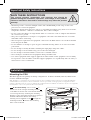
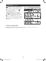
Mounting the PDU
The PDU supports five primary mounting configurations: 1U Rack, 0U Rack (Vertical), Wall, Under-
Counter and Reduced-Depth.
Note: Regardless of configuration, the user must determine the fitness of hardware and procedures before mounting. The PDU and
included hardware are designed for common rack and rack enclosure types and may not be appropriate for all applications. Exact
mounting configurations may vary. Screws for attaching the mounting brackets to the PDU are included. Use only the screws supplied by
the manufacturer, or their exact equivalent (#6-32, 3/16" flat head).
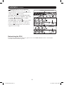
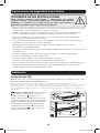
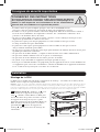
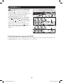
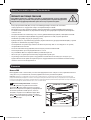
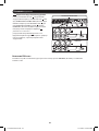
1-1 1U Rack Mounting: Use 3 screws
A
to
attach each of the 2 longer mounting brackets
B
to the PDU as shown. You can mount the PDU in
a recessed position by attaching the mounting
brackets so they extend beyond the front panel of
the PDU. Mount the PDU in the rack by
inserting 4 user-supplied screws
C
through the
mounting brackets
D
and into the mounting
holes of the rack rails.
17-10-354-932718.indb 2 11/17/2017 8:38:10 AM

1-2
A
B
C
D
1-3
A
B
C
D
A
B
1-4
C
D
A
B
1-5
C
D
3
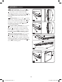
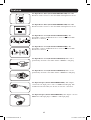
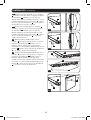
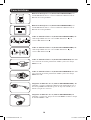
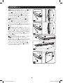
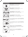
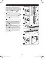
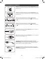
1-2 0U Rack Mounting: Use 3 screws
A
to
attach each of the 2 shorter mounting brackets
B
to the PDU as shown. Mount the PDU
vertically by inserting 2 or more user-supplied
screws
C
through the mounting brackets
D
and
into mounting points in the rack or rack
enclosure.
1-3 Wall Mounting: Use 3 screws
A
to attach
each of the 2 shorter mounting brackets
B
to the
PDU as shown. Mount the PDU to the wall by
inserting 2 or more user-supplied screws
C
through the mounting brackets
D
and into
secure mounting points.
1-4 Under-Counter Mounting: Use 3 screws
A
to attach each of the 2 shorter mounting
brackets
B
to the PDU as shown. Mount the
PDU under the counter by inserting 2 or more
user-supplied screws
C
through the mounting
brackets
D
and into secure mounting points.
1-5 Reduced-Depth Mounting: Use 3 screws
A
to attach each of the 2 shorter mounting
brackets
B
to the PDU as shown. Mount the
PDU to a stable surface with the outlets facing
upward by inserting 2 or more user-supplied
screws
C
through the mounting brackets
D
and
into secure mounting points.
Installation continued
17-10-354-932718.indb 3 11/17/2017 8:38:12 AM

2-1
88
PDUMH15HVNET
PDUMH15NET/PDUMH20NET
A
B
C
88
2-2
PDUMH20HVNET
B
B
A
A
C
C
A
2-3
4
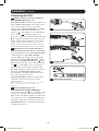
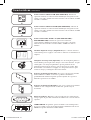
Connecting the PDU
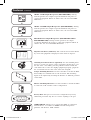
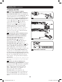
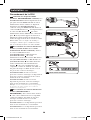
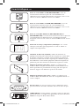
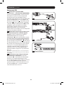
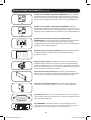
2-1 NEMA Adapter Connection (Optional -
PDUMH20HVNET Only): The
PDUMH20HVNET includes a plug adapter that
adds a NEMA L6-20P plug to the input power
cord. Use this adapter only if you will be
connecting the PDUMH20HVNET to a NEMA
L6-20R outlet. Insert the IEC 60320 C19
connector
A
of the adapter into the IEC 60320
C20 connector
B
of the input power cord.
Secure the connection with the retention bracket
C
by using the included bolts to fasten the two
halves of the bracket around the connection as
shown. Caution: To avoid the risk of electric
shock, ensure that the Neutral (L2) conductor
has been identified before connecting the PDU.
2-2 Input Power Cord Connection (Select
Models with Unattached Power Cords Only):
Insert the IEC 60320 C19 (PDUMH20HVNET)
or IEC 60320 C13 (PDUMH15HVNET)
connector
A
of the input power cord into the
IEC 60320 C20 (PDUMH20HVNET) or IEC
60320 C14 (PDUMH15HVNET) inlet
B
of the
PDU. Connect the other end of the input power
cord
C
to a compatible source of AC power,
such as a UPS system, PDU or utility outlet.
The PDU should be provided with over-current
protection: PDUMH20HVNET should be
provided with a maximum 20A branch-rated
over-current protection device;
PDUMH15HVNET should be provided with a
maximum 15A branch-rated over-current
protection device.
Note: The AC power source should not share a circuit with a
heavy electrical load (such as an air conditioner or
refrigerator).
2-3 Connect Input Power Cord
(PDUMH15NET and PDUMH20NET):
Connect the input plug
A
to a compatible source
of AC power, such as a UPS system, PDU or
utility outlet. The PDU should be provided with
over-current protection: PDUMH15NET with a
maximum 15A branch-rated protection device.
PDUMH20NET with a maximum 20A branch-
rated protection device.
Installation continued
17-10-354-932718.indb 4 11/17/2017 8:38:14 AM

15
2-4
A
B
C
D
PDUMH20NET
PDUMH15NET
PDUMH15HVNET/PDUMH20HVNET
B
B
D
D
C
C
5
Installation continued
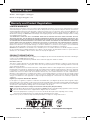
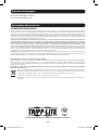
2-4 Equipment Power Cord Connection:
Insert the IEC 60320 C14 connectors
A
of the
equipment power cords into the IEC 60320 C13
output receptacles
B
of the PDU
(PDUMH15HVNET and PDUMH20HVNET).
Insert power cords into the NEMA 5-15R output
receptacles
B
(PDUMH15NET) or NEMA
5-15/20R output receptacles
B
(PDUMH20NET). The LED
C
near each output
receptacle illuminates when the receptacle is
ready to distribute live AC power. The digital
load meter
D
will display the total connected
equipment load in amps.
Networking the PDU
For network configuration instructions, please refer to the WEBCARDLX owner’s manual (PN
93358E) included with this product.
17-10-354-932718.indb 5 11/17/2017 8:38:15 AM

A
B
A
B
6
Features
AC Input Power Inlet (Model PDUMH15HVNET): The IEC
60320 C14 inlet connects to the detachable AC Input Power Cord.
AC Input Power Inlet (Model PDUMH20HVNET): The IEC
60320 C20 inlet connects to the detachable AC Input Power Cord.
AC Input Power Cord (Model PDUMH15HVNET): The
detachable cord has an IEC 60320 C13 connector
A
and an IEC
60320 C14 connector
B
.
AC Input Power Cord (Model PDUMH20HVNET): The
detachable cord has an IEC 60320 C19 connector
A
and an IEC
60320 C20 connector
B
.
AC Input Power Cord (Model PDUMH15NET): The cord is
permanently attached to the PDU and has a NEMA 5-15P plug.
AC Input Power Cord (Model PDUMH20NET): The cord is
permanently attached to the PDU and has a NEMA L5-20P plug.
AC Input Adapter (Model PDUMH20HVNET): The adapter
converts the AC input power cord to a NEMA L6-20P plug. The
included retention bracket (not shown) secures the connection.
AC Input Adapter (Model PDUMH20NET): The adapter converts
NEMA L5-20P input plugs to NEMA 5-20P input plugs.
17-10-354-932718.indb 6 11/17/2017 8:38:17 AM

RESET
STATUS
CONFIG
7
NEMA 5-15R Output Receptacles (PDUMH15NET): During
normal operation, the output receptacles distribute AC power to
connected equipment. When an outlet is live, the associated LED
illuminates.
NEMA 5-15/20R Output Receptacles (PDUMH20NET): During
normal operation, the output receptacles distribute AC power to
connected equipment. When an outlet is live, the associated LED
illuminates.
IEC 60320 C13 Output Receptacles (PDUMH15HVNET &
PDUMH20HVNET): During normal operation, the output
receptacles distribute AC power to connected equipment. When an
outlet is live, the associated LED illuminates.
Digital Load Meter (Ammeter): The total electrical current drawn
by connected equipment is displayed on the meter in amperes.
C14 Plug-Lock Insert Sleeve (Optional): Use the included plastic
sleeves to secure C13 power cords to C14 inlets. Fit the sleeve over
the end of the cord, making sure the pull-tabs remain outside the
cord and the fit is secure. To unplug equipment properly, grip both
the cord and the insert’s tabs at the same time and pull.
Longer Mounting Brackets: Use these brackets to mount the PDU
horizontally in a standard rack or rack enclosure. The mounting
depth can be adjusted by attaching the brackets to different positions
on the PDU.
Shorter Mounting Brackets: Use these brackets to mount the PDU
in a 0U rack, wall or under-counter configuration.
Factory Port: The port is reserved for configuration by factory
authorized personnel only. Do not connect anything to the port.
WEBCARDLX: Allows you to operate this PDU as a managed
network device, accessible via SNMP network management
platform, web browser, SSH or Telnet.
Features continued
17-10-354-932718.indb 7 11/17/2017 8:38:19 AM

8
Warranty and Product Registration
LIMITED WARRANTY
Seller warrants this product, if used in accordance with all applicable instructions, to be free from original defects in material
and workmanship for a period of 2 years from the date of initial purchase. If the product should prove defective in material or
workmanship within that period, Seller will repair or replace the product, in its sole discretion. Service under this Warranty can
only be obtained by your delivering or shipping the product (with all shipping or delivery charges prepaid) to: Tripp Lite, 1111
W. 35th Street, Chicago, IL 60609 USA. Seller will pay return shipping charges. Visit www.tripplite.com/support before sending
any equipment back for repair.
THIS WARRANTY DOES NOT APPLY TO NORMAL WEAR OR TO DAMAGE RESULTING FROM ACCIDENT, MISUSE,
ABUSE OR NEGLECT. SELLER MAKES NO EXPRESS WARRANTIES OTHER THAN THE WARRANTY EXPRESSLY SET
FORTH HEREIN. EXCEPT TO THE EXTENT PROHIBITED BY APPLICABLE LAW, ALL IMPLIED WARRANTIES, INCLUDING
ALL WARRANTIES OF MERCHANTABILITY OR FITNESS, ARE LIMITED IN DURATION TO THE WARRANTY PERIOD SET
FORTH ABOVE; AND THIS WARRANTY EXPRESSLY EXCLUDES ALL INCIDENTAL AND CONSEQUENTIAL DAMAGES.
(Some states do not allow limitations on how long an implied warranty lasts, and some states do not allow the exclusion or
limitation of incidental or consequential damages, so the above limitations or exclusions may not apply to you. This Warranty
gives you specific legal rights, and you may have other rights which vary from jurisdiction to jurisdiction).
WARNING: The individual user should take care to determine prior to use whether this device is suitable, adequate or safe for
the use intended. Since individual applications are subject to great variation, the manufacturer makes no representation or
warranty as to the suitability or fitness of these devices for any specific application.
PRODUCT REGISTRATION
Visit www.tripplite.com/warranty today to register your new Tripp Lite product. You'll be automatically entered into a drawing for
a chance to win a FREE Tripp Lite product!*
* No purchase necessary. Void where prohibited. Some restrictions apply. See website for details.
FCC Notice, Class A
This device complies with part 15 of the FCC Rules. Operation is subject to the following two conditions: (1) This device may
not cause harmful interference, and (2) this device must accept any interference received, including interference that may
cause undesired operation.
Note: This equipment has been tested and found to comply with the limits for a Class A digital device, pursuant to part 15 of
the FCC Rules. These limits are designed to provide reasonable protection against harmful interference when the equipment
is operated in a commercial environment. This equipment generates, uses, and can radiate radio frequency energy and, if not
installed and used in accordance with the instruction manual, may cause harmful interference to radio communications.
Operation of this equipment in a residential area is likely to cause harmful interference in which case the user will be required
to correct the interference at his own expense. The user must use shielded cables and connectors with this equipment. Any
changes or modifications to this equipment not expressly approved by Tripp Lite could void the user’s authority to operate this
equipment.
Regulatory Compliance Identification Numbers
For the purpose of regulatory compliance certifications and identification, your Tripp Lite product has been assigned a unique
series number. The series number can be found on the product nameplate label, along with all required approval markings and
information. When requesting compliance information for this product, always refer to the series number. The series number
should not be confused with the marking name or model number of the product.
WEEE Compliance Information for Tripp Lite Customers and Recyclers (European Union)
Under the Waste Electrical and Electronic Equipment (WEEE) Directive and implementing regulations, when customers
buy new electrical and electronic equipment from Tripp Lite they are entitled to:
• Send old equipment for recycling on a one-for-one, like-for-like basis (this varies depending on the country)
• Send the new equipment back for recycling when this ultimately becomes waste
Tripp Lite has a policy of continuous improvement. Specifications are subject to change without notice.
Technical Support
Website: www.tripplite.com/support
E-mail: [email protected]
1111 W. 35th Street, Chicago, IL 60609 USA • www.tripplite.com/support
17-10-354-932718.indb 8 11/17/2017 8:38:19 AM

9
Manual del Propietario
PDUMH15NET / PDUMH20NET
PDU Controlable para Rack
• Entrada y Salida de CA 120V, 60Hz
PDUMH15HVNET / PDUMH20HVNET
PDU Controlable para Rack
• Entrada y Salida de CA 208V / 230V, 50/60Hz
Instrucciones de Seguridad Importantes 10
Instalación 10
Características 14
Soporte Técnico 16
Garantía 16
English 1
Français 17
Русский 25
1111 W. 35th Street, Chicago, IL 60609 EE. UU. • www.tripplite.com/support
Copyright © 2017 Tripp Lite. Todos los derechos reservados.
17-10-354-932718.indb 9 11/17/2017 8:38:19 AM

A
B
A
1-1
C
D
10
CONSERVE ESTAS INSTRUCCIONES
Este manual contiene instrucciones y advertencias que deben
seguirse durante la instalación, operación y almacenamiento de este
producto. La omisión en la observancia de estas instrucciones y
advertencias puede afectar la garantía del producto.
Instrucciones de Seguridad Importantes
• El PDU proporciona múltiples tomacorrientes convenientes, pero NO proporciona protección contra
sobretensiones o ruido en la línea para los equipos conectados.
• El PDU está diseñado solo para uso en interiores en un entorno controlado lejos de humedad
excesiva, temperaturas extremas, contaminantes conductivos, polvo o luz del sol directa.
• No conecte el PDU a un toma corriente que no esté conectada a tierra o cables de extensión o
adaptadores que eliminen la conexión a tierra.
• Los requerimientos de alimentación para cada dispositivo conectado al PDU no debe exceder la
capacidad de carga de cada toma corriente individual.
• El requerimiento de energía total para el equipo conectado al PDU no debe exceder la
capacidad de carga máxima del PDU.
• No perfore ni intente abrir ninguna parte del gabinete del PDU. No tiene partes a las que el usuario
pueda dar servicio.
• No intente modificar el PDU, incluso las clavijas de entrada y los cables de alimentación.
• No intente usar el PDU si se daña cualquier parte.
• No intente instalar el PDU en una superficie inestable o no segura.
• Nunca intente instalar equipos eléctricos durante una tormenta eléctrica.
• No se recomienda el uso de este equipo en aplicaciones de soporte de vida en donde la falla de este
equipo pueda razonablemente hacer esperar que cause la falla del equipo de soporte de vida o
afectar significativamente su seguridad o efectividad.
Instalación
Instalación del PDU
El PDU soporta cinco configuraciones primarias de instalación: Rack de 1U, Rack 0U (vertical), en la
Pared, Bajo el Mostrador y Profundidad Reducida
Nota: Sin importar la configuración, antes de la instalación, el usuario debe determinar la adecuación de los accesorios y
procedimientos. El PDU y los accesorios incluidos están diseñados para tipos comunes de racks y gabinetes y pueden no ser apropiados
para todas las aplicaciones. Las configuraciones de instalación exactas pueden variar. Están incluidos los tornillos para fijar los
soportes para instalación al PDU. Use solamente los tornillos suministrados por el fabricante o su equivalente exacto (#6-32, cabeza
plana de 3/16”).
1-1 Instalación en Rack de 1U: Use 3 tornillos
A
para instalar cada uno de los 2 soportes
grandes de instalación
B
al PDU como se
muestra. Puede instalar el PDU en una posición
empotrada adjuntando los soportes de instalación
para que sobresalga de la parte frontal del PDU.
Instale el PDU en el rack insertando 4 tornillos
suministrados por el usuario
C
a través de los
soportes de instalación
D
y en los orificios de
instalación de los rieles del rack.
17-10-354-932718.indb 10 11/17/2017 8:38:20 AM

1-2
A
B
C
D
1-3
A
B
C
D
A
B
1-4
C
D
A
B
1-5
C
D
11
1-1 Instalación en 0U de Rack: Use 3 tornillos
A
para fijar cada uno de los 2 soportes pequeños
de instalación
B
al PDU como se muestra.
Instale verticalmente el PDU insertando 2 o más
tornillos suministrados por el usuario
C
a través
de los soportes de instalación
D
y en los puntos
de instalación en el rack o gabinete.
1-3 Instalación en la Pared: Use 3 tornillos
A
para fijar cada uno de los 2 soportes pequeños
de instalación
B
al PDU como se muestra.
Instale el PDU en la pared insertando 2 o más
tornillos suministrados por el usuario
C
a través
de los soportes de instalación
D
y en puntos
seguros de instalación.
1-4 Instalación Bajo el Mostrador: Use 3
tornillos
A
para fijar cada uno de los 2 soportes
pequeños de instalación
B
al PDU como se
muestra. Instale el PDU bajo el mostrador
insertando 2 o más tornillos suministrados por el
usuario
C
a través de los soportes de instalación
D
y en puntos seguros de instalación.
1-5 Instalación de Profundidad Reducida: Use 3
tornillos
A
para fijar cada uno de los 2 soportes
pequeños de instalación
B
al PDU como se
muestra. Instale el PDU en una superficie
estable con los tomacorrientes viendo hacia arriba
insertando 2 o más tornillos suministrados por el
usuario
C
a través de los soportes de instalación
D
y en puntos seguros de instalación.
Instalación continuación
17-10-354-932718.indb 11 11/17/2017 8:38:20 AM

2-1
88
PDUMH15HVNET
PDUMH15NET / PDUMH20NET
A
B
C
88
2-2
PDUMH20HVNET
B
B
A
A
C
C
A
2-3
12
Conexión del PDU
2-1 Conexión de Adaptador NEMA
(Opcional - PDUMH20HVNET Solamente):
El PDUMH20HVNET incluye un adaptador de
clavija que agrega una clavija NEMA L6-20P al
cable de alimentación. Use este adaptador
únicamente si conectará el PDUMH20HVNET a
un tomacorrientes NEMA L6-20R. Insert el
conector IEC 60320 C19
A
del adaptador en el
conector IEC 60320 C20
B
del cable de
alimentación. Asegure la conexión con el
soporte de sujeción
C
usando los tornillos
incluidos para sujetar las dos mitades del
soporte alrededor de la conexión, como se
muestra. Precaución: Para evitar el riesgo de
una descarga eléctrica, asegúres de que el
conductor neutro (L2) haya sido identificado
antes de conectar el PDU.
2-2 Conexión del Cable de Alimentación de
Entrada (Modelos Selectos con Cables de
Alimentación no Conectados Solamente):
Inserte el conector IEC 60320 C19
(PDUMH20HVNET) o IEC 60320 C13
(PDUMH15HVNET)
A
del cable de
alimentación en la entrada IEC 60320 C20
(PDUMH20HVNET) o IEC 60320 C14
(PDUMH15HVNET)
B
del PDU. Conecte el
otro extremo del cable de alimentación
C
a una
fuente compatible de energía de CA como un
sistema UPS, PDU o tomacorriente de la red
pública. El PDU debe ser proveído con protección
de sobrecorriente: El PDUMH20HVNET debe
estar provisto con un dispositivo de protección
de sobrecorriente de especificación de ramal de
20A máximo; El PDUMH15HVNET debe estar
provisto con un dispositivo de protección de
sobrecorriente con especificación de ramal de
15A máximo.
Nota: La fuente de energía de CA no debe compartir un circuito
con una carga eléctrica pesada (como un aire acondicionado o
refrigerador).
2-3 Conecte el Cable de Alimentación
(PDUMH15NET y PDUMH20NET): Conecte
la clavija de entrada
A
a una fuente compatible
de energía de CA, como un sistema UPS,
PDU o tomacorriente de energía de la red
pública. El PDU debe estar equipado con
protección contra sobrecorriente;
PDUMH15NET con un dispositivo de
protección especificado para 15A máximo por
ramal. PDUMH20NET con un dispositivo de
protección especificado para 20A máximo por
ramal.
Instalación continuación
17-10-354-932718.indb 12 11/17/2017 8:38:21 AM

15
2-4
A
B
C
D
PDUMH20NET
PDUMH15NET
PDUMH15HVNET / PDUMH20HVNET
B
B
D
D
C
C
13
Instalación continuación
2-4 Conexión de Cable de Alimentación del
Equipo: Inserte los conectores IEC 60320 C14
A
de los cables de alimentación de los equipos
en los tomacorrientes IEC 60320 C13
B
del
PDU (PDUMH15HVNET y
PDUMH20HVNET). Inserte los cables de
alimentación en los tomacorrientes NEMA
5-15R
B
(PDUMH15NET) o tomacorrientes
NEMA 5-15/20R
B
(PDUMH20NET). El LED
C
junto a cada tomacorrientes se enciende
cuando el tomacorriente está listo para distribuir
energía viva de CA. El medidor digital de carga
D
mostrará la carga total del equipo conectado
en amperes.
Conexión a Red del PDU
Para obtener instrucciones de configuración de red, consulte el manual del usuario de la tarjeta
WEBCARDLX (PN 93358E) incluido con este producto.
17-10-354-932718.indb 13 11/17/2017 8:38:21 AM

A
B
A
B
14
Características
Entrada de Energía de CA (Modelo PDUMH15HVNET): La
entrada IEC 60320 C14 se conecta al Cable de Alimentación de
Entrada de CA desprendible.
Entrada de Energía de CA (Modelo PDUMH20HVNET): La
entrada IEC 60320 C20 se conecta al Cable de Alimentación de
Entrada de CA desprendible.
Cable de Alimentación de CA (Modelo PDUMH15HVNET): El
cable desprendible tiene un conector IEC 60320 C13
A
y un
conector IEC 60320 C14
B
.
Cable de Alimentación de CA (Modelo PDUMH20HVNET): El
cable desprendible tiene un conector IEC 60320 C19
A
y un
conector IEC 60320 C20
B
.
Cable de Alimentación de CA (Modelo PDUMH15NET): El cable
está conectado de forma permanente al PDU y tiene una clavija
NEMA 5-15P.
Cable de Alimentación de CA (Modelo PDUMH20NET): El cable
está conectado de forma permanente al PDU y tiene una clavija
NEMA L5-20P.
Adaptador de Entrada de CA (Modelo PDUMH20HVNET): El
adaptador convierte el Cable de Alimentación de Entrada de CA a
una clavija NEMA L6-20P. El soporte de sujeción incluido (no se
muestra) asegura la conexión.
Adaptador de Entrada de CA (Modelo PDUMH20NET): El
adaptador convierte las clavijas de entrada NEMA L5-20P a clavijas
de entrada NEMA 5-20P.
17-10-354-932718.indb 14 11/17/2017 8:38:22 AM

RESET
STATUS
CONFIG
15
Tomacorrientes NEMA 5-15R (PDUMH15NET): Durante la
operación normal, los tomacorrientes distribuyen energía de CA al
equipo conectado. Cuando un tomacorrientes está encendido, el LED
asociado se ilumina.
Tomacorrientes NEMA 5-15/20R (PDUMH20NET): Durante la
operación normal, los tomacorrientes distribuyen energía de CA al
equipo conectado. Cuando un tomacorrientes está encendido, el LED
asociado se ilumina.
Tomacorrientes IEC 60320 C13 (PDUMH15HVNET y
PDUMH20HVNET): Durante la operación normal, los
tomacorrientes distribuyen energía de CA al equipo conectado.
Cuando un tomacorrientes está encendido, el LED asociado se
ilumina.
Medidor Digital de Carga (Amperímetro): La corriente eléctrica
total tomada por los equipos conectados se muestra en el medidor en
amperes.
Manguito de Clavija C14 (Opcional): Use los manguitos plásticos
C14 incluidos para asegurar las clavijas a los tomacorrientes. Acople
el manguito a la clavija asegurándose que las pestañas de tiro
permanezcan fuera de la clavija y que la sujeción sea segura. Para
desenchufar correctamente el equipo, use las pestañas de tiro para
retirar la clavija y el manguito del tomacorriente.
Soportes de Instalación Grandes: Use estos soportes para instalar
horizontalmente el PDU en un rack o gabinete estándar. La
profundidad de instalación puede ajustarse fijando los soportes a
diferentes posiciones en el PDU.
Soportes de Instalación Pequeños: Use estos soportes para instalar
el PDU en una configuración de rack de 0U, pared o bajo el
mostrador.
Puerto de Fábrica: El puerto está reservado para la configuración
solo por parte de personal autorizado de fábrica. No conecte nada en
el puerto.
WEBCARDLX: Le permite operar este PDU como un dispositivo
de red, accesible a través de la plataforma de administración de red
SNMP, navegador de Internet, SSH o Telnet.
Características continuación
17-10-354-932718.indb 15 11/17/2017 8:38:22 AM

16
Garantía
GARANTÍA LIMITADA
El vendedor garantiza este producto, si se usa de acuerdo con todas las instrucciones aplicables, de que está libre de defectos
en material y mano de obra por un período de 2 años a partir de la fecha de compra inicial. Si el producto resulta defectuoso
en material o mano de obra dentro de ese período, el vendedor reparará o reemplazará el producto a su entera discreción. El
servicio bajo esta garantía sólo puede obtenerse enviando o embarcando el producto (con todos los cargos de envío o
embarque prepagados) a: Tripp Lite, 1111 W. 35th Street, Chicago, IL 60609 EE UU. El vendedor reembolsará los cargos de
embarque. Antes de devolver cualquier equipo para reparación, visite www.tripplite.com/support.
ESTA GARANTÍA NO APLICA AL DESGASTE NORMAL O A DAÑOS RESULTANTES DE ACCIDENTES, MAL USO, ABUSO
O NEGLIGENCIA. EL VENDEDOR NO OTORGA GARANTÍAS EXPRESAS DISTINTAS DE LA ESTIPULADA EN EL
PRESENTE. SALVO EN LA MEDIDA EN QUE LO PROHÍBAN LAS LEYES APLICABLES, TODAS LAS GARANTÍAS
IMPLÍCITAS, INCLUYENDO TODAS LAS GARANTÍAS DE COMERCIALIZACIÓN O IDONEIDAD, ESTÁN LIMITADAS EN
DURACIÓN AL PERÍODO DE GARANTÍA ESTABLECIDO; ASIMISMO, ESTA GARANTÍA EXCLUYE EXPRESAMENTE
TODOS LOS DAÑOS INCIDENTALES E INDIRECTOS. (Algunos estados no permiten limitaciones en cuanto dura una
garantía y algunos estados no permiten la exclusión de limitación de daños incidentales o consecuenciales, de modo que las
limitaciones anteriores pueden no aplicar para usted. Esta garantía le otorga derechos legales específicos y usted puede tener
otros derechos que pueden variar de una jurisdicción a otra).
ADVERTENCIA: Antes de usarlo, cada usuario debe debe tener cuidado al determinar si este dispositivo es adecuado o
seguro para el uso previsto. Ya que las aplicaciones individuales están sujetas a gran variación, el fabricante no garantiza la
adecuación de estos dispositivos para alguna aplicación específica.
Números de Identificación de Conformidad Regulatoria
Para el propósito de certificaciones e identificación de conformidad con las normas, su producto Tripp Lite ha recibido un
número de serie exclusivo. El número de serie puede encontrarse en la etiqueta de placa de identificación, junto con todas las
marcas e información requeridas de aprobación. Al solicitar información de conformidad para este producto, refiera siempre
el número de serie. El número de serie no debe confundirse con el nombre de la marca o el número de modelo del producto.
Información de Cumplimiento con WEEE por los Clientes y Recicladores de Tripp Lite (Unión Europea)
Soporte Técnico
www.tripplite.com/support
Correo Electrónico: [email protected]
1111 W. 35th Street, Chicago, IL 60609 EE. UU. • www.tripplite.com/support
Bajo la Directiva de Desechos de Equipos Eléctricos y Electrónicos (WEEE) [Waste Electrical and Electronic
Equipment] y regulaciones aplicables, cuando los clientes adquieren un nuevo equipo eléctrico y electrónico de
Tripp Lite están obligados a:
• Enviar el equipo viejo a reciclado en una base de uno por uno, equivalente por equivalente (esto varía de un país
a otro)
• Regrese el equipo nuevo para reciclado una vez que finalmente sea un desecho
Tripp Lite tiene una política de mejora continua. Las especificaciones están sujetas a cambio sin previo aviso.
17-10-354-932718.indb 16 11/17/2017 8:38:23 AM

17
Manuel de l'utilisateur
PDUMH15NET/PDUMH20NET
PDU en bâti commutée
• Entrée et sortie CA, 120 V, 60 Hz
PDUMH15HVNET/PDUMH20HVNET
PDU en bâti commutée
• Entrée et sortie CA, 208/230 V, 50/60 Hz
Consignes de sécurité importantes 18
Installation 18
Caractéristiques 22
Soutien technique 24
Garantie 24
1111 W. 35th Street, Chicago, IL 60609 USA • www.tripplite.com/support
Droits d'auteur © 2017 Tripp Lite. Tous droits réservés.
English 1
Español 9
Русский 25
17-10-354-932718.indb 17 11/17/2017 8:38:23 AM

A
B
A
1-1
C
D
18
CONSERVEZ CES INSTRUCTIONS
Ce manuel contient des instructions et des avertissements qui doivent
être respectés pendant l'installation, l'utilisation et l'entreposage de ce
produit. Le non-respect de ces instructions et de ces avertissements
pourrait avoir une incidence sur la garantie du produit.
Consignes de sécurité importantes
• La PDU fournit des prises multiples pratiques, mais elle ne FOURNIT PAS de
protection contre les surtensions ou les bruits de ligne pour l'équipement connecté.
• La PDU est conçue pour être utilisée à l'intérieur uniquement, dans un environnement contrôlé, à
l'écart de l'excès d'humidité, des températures extrêmes, des contaminants conducteurs, de la
poussière et de la lumière directe du soleil.
• Ne pas raccorder la PDU à une prise non mise à la masse ou à des rallonges électriques ou des
adaptateurs qui éliminent la connexion à la masse.
• La puissance requise pour chaque équipement raccordé à la PDU ne doit pas excéder
la charge nominale de la prise individuelle.
• La puissance totale requise pour l'équipement raccordé à la PDU ne doit pas excéder la
charge nominale maximum pour la PDU.
• Ne pas percer ou tenter d'ouvrir une quelconque partie du boîtier de la PDU. Il n'existe aucune pièce
réparable par l'utilisateur à l'intérieur.
• Ne pas tenter de modifier la PDU, y compris les fiches d'entrée et les câbles d'alimentation.
• Ne pas tenter d'utiliser la PDU si une de ses pièces est endommagée.
• Ne pas tenter de monter la PDU sur une surface précaire ou instable.
• Ne jamais essayer d'installer un équipement électrique pendant un orage.
• Il n'est pas recommandé d'utiliser cet équipement pour des appareils de survie où une défaillance de
cet équipement peut, selon toute vraisemblance, entraîner la défaillance de l’appareil de maintien de
la vie ou affecter de façon majeure sa sécurité ou son efficacité.
Installation
Montage de la PDU
La PDU peut accueillir cinq principales configurations de montage : 1U en bâti, 0U en bâti (vertical),
murale, sous le comptoir et à profondeur réduite.
Remarque : Quelle que soit la configuration, l'utilisateur doit déterminer l'aptitude du matériel et des procédures avant de procéder au
montage. La PDU et le matériel inclus sont conçus pour les bâtis et les boîtiers pour bâtis communs et peuvent ne pas être appropriés
pour toutes les applications. Les configurations de montage exactes peuvent varier. Les vis pour fixer les supports de montage à la PDU
sont incluses. Utiliser uniquement les vis fournies par le fabricant ou leur équivalent exact (no 6-32, 3/16 po à tête plate).
1-1 Montage en bâti 1U : Utiliser 3 vis
A
pour
fixer chacun des 2 supports de montage plus
longs
B
à la PDU comme illustré. La PDU peut
être montée dans une position encastrée en fixant
les supports de montage de façon à ce qu'ils
dépassent le panneau avant de la PDU. Monter la
PDU au bâti en insérant les quatre vis fournies
par l'utilisateur
C
à travers les supports de
montage
D
, puis dans les trous de montage des
rails du bâti.
17-10-354-932718.indb 18 11/17/2017 8:38:23 AM

1-2
A
B
C
D
1-3
A
B
C
D
A
B
1-4
C
D
A
B
1-5
C
D
19
1-2 Montage en bâti 0U : Utiliser 3 vis
A
pour
fixer chacun des 2 supports de montage plus
courts
B
à la PDU comme illustré. Monter la
PDU verticalement en insérant au moins deux
vis fournies par l'utilisateur
C
à travers les
supports de montage
D
et dans les points de
montage dans le bâti ou le boîtier pour bâti.
1-3 Montage mural : Utiliser 3 vis
A
pour
fixer chacun des 2 supports de montage plus
courts
B
à la PDU comme illustré. Monter la
PDU au mur en insérant au moins deux vis
fournies par l'utilisateur
C
à travers les supports
D
de montage et dans les points de montage
solides.
1-4 Montage sous le comptoir : Utiliser 3 vis
A
pour fixer chacun des 2 supports de montage
plus courts
B
à la PDU comme illustré. Monter
la PDU sous le comptoir en insérant au moins
deux vis fournies par l'utilisateur
C
à travers les
supports
D
de montage et dans les points de
montage solides.
1-5 Montage à profondeur réduite : Utiliser 3
vis
A
pour fixer chacun des 2 supports de
montage plus courts
B
à la PDU comme illustré.
Monter la PDU à une surface stable avec les
sorties tournées vers le haut en insérant au
moins deux vis fournies par l'utilisateur
C
à
travers les supports de montage
D
et dans les
points de montage solides.
Installation suite
17-10-354-932718.indb 19 11/17/2017 8:38:24 AM

2-1
88
PDUMH15HVNET
PDUMH15NET/PDUMH20NET
A
B
C
88
2-2
PDUMH20HVNET
B
B
A
A
C
C
A
2-3
20
Raccordement de la PDU
2-1 Connexion de l'adaptateur NEMA
(facultatif - PDUMH20HVNET seulement) : La
PDUMH20HVNET inclut un adaptateur de fiche
qui ajoute une fiche NEMA L6-20P au cordon
d'alimentation d'entrée. Utiliser cet adaptateur
uniquement si la PDUMH20HVNET est
connectée à une prise NEMA L6-20R. Insérer le
connecteur IEC 60320 C19
A
de l'adaptateur dans
le connecteur IEC 60320 C20
B
du cordon
d'alimentation d'entrée. Maintenir la connexion en
place
C
au moyen d'un support de rétention en
utilisant les boulons inclus pour fixer les deux
moitiés du support autour de la connexion comme
illustré. Pour éviter les risques de décharges
électriques, s'assurer que le conducteur neutre
(L2) a été identifié avant de raccorder la PDU.
2-2 Raccordement du cordon d'alimentation
d'entrée (certains modèles avec cordons
d'alimentation détachés seulement) : Insérer
le connecteur IEC 60320 C19
(PDUMH20HVNET) ou IEC 60320 C13
(PDUMH15HVNET)
A
du cordon
d'alimentation d'entrée dans l'entrée IEC 60320
C20 (PDUMH20HVNET) ou IEC 60320 C14
(PDUMH15HVNET)
B
de la PDU. Brancher
l'autre extrémité du cordon d'alimentation
d'entrée
C
à une source d'alimentation CA
compatible, comme un onduleur, une PDU ou
une prise électrique. La PDU devrait recevoir
une protection contre les surcharges :
PDUMH20HVNET devrait recevoir une
protection contre les surcharges; un dispositif de
protection contre les surcharges d'une section
nominale de 20 A maximum;
PDUMH15HVNET devrait recevoir un
dispositif de protection contre les surcharges
d'une section nominale de 15 A maximum.
Remarque : La source d'alimentation CA ne doit pas partager
un circuit avec une charge électrique élevée (comme un
climatiseur ou un réfrigérateur).
2-3 Raccordement du cordon d'alimentation
d'entrée (PDUMH15NET et
PDUMH20NET) : Raccorder la fiche d'entrée
A
à une source d'alimentation CA compatible,
comme un onduleur, une PDU ou une prise
électrique. La PDU devrait recevoir une
protection contre les surcharges :
PDUMH15NET avec un dispositif de protection
d'une section nominale de 15 A maximum.
PDUMH20NET avec un dispositif de protection
d'une section nominale de 20 A maximum.
Installation suite
17-10-354-932718.indb 20 11/17/2017 8:38:25 AM

15
2-4
A
B
C
D
PDUMH20NET
PDUMH15NET
PDUMH15HVNET/PDUMH20HVNET
B
B
D
D
C
C
21
Installation suite
2-4 Raccordement du cordon d'alimentation
de l'équipement : Insérer les connecteurs IEC
60320 C14
A
des cordons d'alimentation de
l'équipement dans les prises de sortie IEC 60320
C13
B
de la PDU (PDUMH15HVNET et
PDUMH20HVNET). Insérer les cordons
d'alimentation dans les prises de sortie NEMA
5-15R
B
(PDUMH15NET) ou les prises de
sortie NEMA 5-15/20R
B
(PDUMH20NET). Le
voyant à DEL
C
près de chaque sortie s'allume
lorsque la sortie est prête à fournir une
alimentation CA sous tension. L'indicateur de
charge (ampèremètre) numérique
D
affichera la
charge totale de l'équipement connecté en
ampères.
Fonctionnement en réseau de la PDU
Pour des instructions sur la configuration en réseau, veuillez vous référer au manuel de l'utilisateur de
la WEBCARDLX (n° de pièce 93358E) inclus avec ce produit.
17-10-354-932718.indb 21 11/17/2017 8:38:25 AM

A
B
A
B
22
Caractéristiques
Entrée d'alimentation de l'entrée CA (modèle
PDUMH15HVNET) : L'entrée IEC 60320 C14 se raccorde au
cordon d'alimentation d'entrée CA amovible.
Entrée d'alimentation de l'entrée CA (modèle
PDUMH20HVNET) : L'entrée IEC 60320 C20 se raccorde au
cordon d'alimentation de l'entrée CA amovible.
Cordon d'alimentation de l'entrée CA (modèle
PDUMH15HVNET) : Le cordon amovible comporte un connecteur
IEC 60320 C13
A
et un connecteur IEC 60320 C14
B
.
Cordon d'alimentation de l'entrée CA (modèle
PDUMH20HVNET) : Le cordon amovible comporte un connecteur
IEC 60320 C19
A
et un connecteur IEC 60320 C20
B
.
Cordon d'alimentation de l'entrée CA (modèle PDUMH15NET) :
Le cordon est attaché en permanence à la PDU et comporte une fiche
d'entrée NEMA 5-15P.
Cordon d'alimentation de l'entrée CA (modèle PDUMH20NET) :
Le cordon est attaché en permanence à la PDU et comporte une fiche
NEMA L5-20P.
Adaptateur d'entrée CA (modèle PDUMH20HVNET) :
L'adaptateur convertit le cordon d'alimentation d'entrée CA en une
fiche NEMA L6-20P. Le support de rétention inclus (non illustré)
retient la connexion en place.
Adaptateur de l'entrée CA (modèle PDUMH20NET) :
L'adaptateur convertit les fiches d'entrée NEMA L5-20P en fiches
d'entrée NEMA 5-20P.
17-10-354-932718.indb 22 11/17/2017 8:38:25 AM

RESET
STATUS
CONFIG
23
Prises de sortie NEMA 5-15R (PDUMH15NET) : Lors du
fonctionnement normal, les prises de sortie distribuent une
alimentation CA à l'équipement branché. Lorsqu'une sortie est sous
tension, le témoin à DEL lui étant associé s'allume.
Prises de sortie NEMA 5-15/20R (PDUMH20NET) : Lors du
fonctionnement normal, les prises de sortie distribuent une
alimentation CA à l'équipement branché. Lorsqu'une sortie est sous
tension, le témoin à DEL lui étant associé s'allume.
Prises de sortie IEC 60320 C13 (PDUMH15HVNET et
PDUMH20HVNET) : Lors du fonctionnement normal, les prises de
sortie distribuent une alimentation CA à l'équipement branché.
Lorsqu'une sortie est sous tension, le témoin à DEL lui étant associé
s'allume.
Indicateur de charge (ampèremètre) numérique : Le courant
électrique total utilisé par l'équipement raccordé est affiché en
ampères sur l'ampèremètre.
Manchons de fiche C14 (facultatif) : Utiliser les manchons en
plastique C14 inclus pour retenir les fiches aux prises de courant. Fixer
le manchon à la fiche en s’assurant que les languettes de préhension
demeurent à l’extérieur de la fiche et qu’il repose solidement en place.
Pour débrancher correctement l’équipement, utiliser les languettes de
préhension pour retirer la fiche et le manchon de la prise de courant.
Supports de montage plus longs : Utiliser ces supports pour
monter la PDU sur le plan horizontal dans un bâti standard ou un
boîtier pour bâtis. La profondeur de montage peut être réglée en
fixant les supports aux différentes positions sur la PDU.
Supports de montage plus courts : Utiliser ces supports pour
monter la PDU dans un bâti 0U, dans une configuration murale ou
sous le comptoir.
Port de l'usine : Le port est réservé pour la configuration par le
personnel autorisé de l'usine seulement. Ne rien raccorder au port.
WEBCARDLX : Permet d'utiliser cette PDU comme un dispositif
géré par le réseau, accessible via la plateforme de gestion de réseau
SNMP, un navigateur Web, SSH ou Telnet.
Caractéristiques suite
17-10-354-932718.indb 23 11/17/2017 8:38:26 AM

24
Garantie
GARANTIE LIMITÉE
Le vendeur garantit ce produit, s'il est utilisé conformément à toutes les instructions applicables, est exempt de tous défauts
de matériaux et de fabrication pour une période de 2 ans à partir de la date d'achat initiale. Si le produit s'avère défectueux en
raison d'un vice de matière ou de fabrication au cours de cette période, le vendeur s'engage à réparer ou remplacer le produit,
à sa seule discrétion. Le service sous cette garantie ne peut être obtenue qu'en livrant ou en expédiant le produit (avec tous
les frais d'expédition ou de livraison prépayés) à : Tripp Lite, 1111 W. 35th Street, Chicago, IL 60609 États-Unis. Le vendeur
paiera les frais d'expédition de retour. Visiter www.tripplite.com/support avant d'envoyer de l'équipement pour réparation.
CETTE GARANTIE NE S'APPLIQUE PAS À L'USURE NORMALE OU AUX DOMMAGES RÉSULTANT D'UNE MAUVAISE
UTILISATION, D'UN ABUS OU D'UNE NÉGLIGENCE. LE VENDEUR NE DONNE AUCUNE GARANTIE EXPRESSE AUTRE
QUE LA GARANTIE EXPRESSÉMENT DÉCRITE DANS LE PRÉSENT DOCUMENT. SAUF DANS LA MESURE INTERDITE
PAR LA LOI APPLICABLE, TOUTE GARANTIE IMPLICITE, Y COMPRIS TOUTES LES GARANTIES DE QUALITÉ
MARCHANDE OU D'ADAPTATION, SONT LIMITÉES À LA PÉRIODE DE GARANTIE CI-DESSUS ET CETTE GARANTIE
EXCLUT EXPRESSÉMENT TOUS DOMMAGES DIRECTS ET INDIRECTS. (Certains États ne permettent pas de limitations
sur la durée d'une garantie implicite, et certains états ne permettent pas l'exclusion ou la limitation des dommages fortuits ou
consécutifs, de sorte que les limitations ou exclusions susmentionnées peuvent ne pas s'appliquer à vous. Cette garantie vous
donne des droits légaux spécifiques, et vous pouvez avoir d'autres droits qui varient selon le territoire).
AVERTISSEMENT : L'utilisateur individuel doit prendre soin de déterminer avant l'utilisation si cet appareil est approprié,
adéquat et sûr pour l'usage prévu. Puisque les utilisations individuelles sont sujettes à des variations importantes, le fabricant
ne fait aucune déclaration ou garantie quant à l'aptitude ou l'adaptation de ces dispositifs pour une application spécifique.
Numéros d'identification à la conformité réglementaire
À des fins de certification de conformité réglementaire et d'identification, un numéro de série unique a été attribué à votre
produit Tripp Lite. Le numéro de série ainsi que toutes les marques d'homologation et les renseignements requis se trouvent
sur la plaque signalétique du produit. Lorsque vous demandez des renseignements concernant la conformité de ce produit,
reportez-vous toujours au numéro de série. Le numéro de série ne doit pas être confondu avec le nom de la marque ou le
numéro de modèle du produit.
Renseignements sur la conformité à la directive DEEE pour les clients de Tripp Lite et les recycleurs (Union européenne)
Soutien technique
Site Web : www.tripplite.com/support
Adresse électronique : [email protected]
1111 W. 35th Street, Chicago, IL 60609 USA • www.tripplite.com/support
En vertu de la directive et des règlements d'application relatifs aux déchets d'équipements électriques et
électroniques (DEEE), lorsque des clients achètent de l'équipement électrique et électronique neuf de Tripp Lite, ils
ont droit :
• D'envoyer l'équipement usagé au recyclage pourvu qu'il remplace un équipement équivalent (cela varie selon
les pays)
• De retourner le nouvel équipement afin qu'il soit recyclé à la fin de sa vie utile.
La politique de Tripp Lite en est une d’amélioration continue. Les spécifications sont sujettes à changement
sans préavis.
17-10-354-932718.indb 24 11/17/2017 8:38:26 AM

25
Руководство пользователя
PDUMH15NET/PDUMH20NET
Управляемый стоечный PDU
• Вход/выход: 120 В, 60 Гц
PDUMH15HVNET/PDUMH20HVNET
Управляемый стоечный PDU
• Вход/выход: 208/230 В, 50/60 Гц
Важные указания по технике безопасности 26
Установка 26
Функциональные возможности 30
Техническая поддержка 32
Гарантийные обязательства 32
English 1
Español 9
1111 W. 35th Street, Chicago, IL 60609 USA • www.tripplite.com/support
Охраняется авторским правом © 2017 Tripp Lite. Перепечатка запрещается.
Français 17
17-10-354-932718.indb 25 11/17/2017 8:38:26 AM

A
B
A
1-1
C
D
26
СОХРАНИТЕ НАСТОЯЩИЕ УКАЗАНИЯ
В настоящем руководстве содержатся указания и предупреждения, которые необходимо
соблюдать в процессе установки, эксплуатации и хранения данного изделия. Игнорирование
этих указаний и предупреждений может привести к потере гарантии на изделие.
Важные указания по технике безопасности
• Блок распределения питания (PDU) оснащен несколькими удобными розетками, но НЕ обеспечивает
защиту подключенного оборудования от выбросов напряжения и шумов в линии.
• PDU предназначен только для использования в закрытых помещениях с регулируемым микроклиматом вдали от
источников повышенной влажности, экстремальных температур, электропроводных загрязнителей, пыли и прямого
солнечного света.
• Не подключайте PDU к незаземленной розетке, а также к удлинителям или переходникам, не имеющим заземления.
• Мощность, потребляемая каждой единицей оборудования, подключенного к PDU, не должна превышать
максимально допустимую нагрузку на отдельную розетку.
• Суммарная мощность, потребляемая оборудованием, подключенным к блоку распределения питания (PDU), не должна
превышать его максимально допустимую нагрузку.
• Не высверливайте отверстий в корпусе PDU и не пытайтесь вскрыть какую-либо его часть. Внутри него нет деталей,
обслуживаемых пользователем.
• Не вносите изменений в конструкцию PDU, включая входные разъемы и кабели питания.
• Не используйте PDU в случае повреждения любой из его частей.
• Не устанавливайте PDU на незакрепленной или неустойчивой поверхности.
• Ни в коем случае не производите монтаж электрооборудования во время грозы.
• Не рекомендуется использование данного оборудования в системах жизнеобеспечения, где его выход из строя
предположительно может привести к перебоям в работе оборудования жизнеобеспечения или в значительной мере
снизить его безопасность или эффективность.
Установка
Монтаж PDU
PDU поддерживает пять основных типов установочной конфигурации: монтаж в стойку высотой 1U, вертикальный монтаж в
стойку (высота 0U), настенный монтаж, монтаж под прилавком и монтаж с уменьшенной глубиной.
Примечание. Независимо от конфигурации, пользователь должен установить пригодность оснастки и предполагаемых процедур до начала монтажа. Блок
распределения питания (PDU) и входящая в его комплект оснастка предназначены для обычных типов шкафов и могут не подходить для всех целей применения.
Установочные конфигурации могут различаться в деталях. В комплект поставки входят винты для крепления монтажных кронштейнов. Используйте только винты,
поставляемые производителем, или их полный аналог (#6-32, 3/16” с потайной головкой).
1-1 Монтаж в стойку высотой 1U: с помощью 3
винтов
A
прикрепите оба удлиненных монтажных
кронштейна
B
к корпусу PDU, как показано на рисунке.
PDU может монтироваться заподлицо путем прикрепления
монтажных кронштейнов таким образом, чтобы они
выходили за переднюю панель PDU. Вмонтируйте PDU в
шкаф/стойку, вставив 4 винта (в комплект поставки не
входят)
C
через монтажные кронштейны
D
в монтажные
направляющие шкафа.
17-10-354-932718.indb 26 11/17/2017 8:38:27 AM

1-2
A
B
C
D
1-3
A
B
C
D
A
B
1-4
C
D
A
B
1-5
C
D
27
1-2 Вертикальный монтаж в стойку (высота 0U): с
помощью 3 винтов
A
прикрепите оба укороченных
монтажных кронштейна
B
к корпусу PDU, как показано на
рисунке. Прикрепите PDU вертикально путем ввертывания
двух или более винтов
C
(не входящих в комплект
поставки) через монтажные кронштейны
D
в монтажные
отверстия стойки или шкафа.
1-3 Настенный монтаж: с помощью 3 винтов
A
прикрепите оба укороченных монтажных кронштейна
B
к
корпусу PDU, как показано на рисунке. Прикрепите PDU к
стене путем ввертывания двух или более винтов
C
(не
входящих в комплект поставки) через монтажные
кронштейны
D
в отверстия, расположенные в точках
надежного крепления.
1-4 Монтаж под прилавком: с помощью 3 винтов
A
прикрепите оба укороченных монтажных кронштейна
B
к
корпусу PDU, как показано на рисунке. Закрепите PDU под
прилавком путем ввертывания двух или более винтов
C
(не входящих в комплект поставки) через монтажные
кронштейны
D
в отверстия, расположенные в точках
надежного крепления.
1-5 Монтаж с уменьшенной глубиной: с помощью 3
винтов
A
прикрепите оба укороченных монтажных
кронштейна
B
к корпусу PDU, как показано на рисунке.
Прикрепите PDU к устойчивой поверхности розетками
вверх путем ввертывания двух или более винтов
C
(не
входящих в комплект поставки) через монтажные
кронштейны
D
в отверстия, расположенные в точках
надежного крепления.
Установка (продолжение)
17-10-354-932718.indb 27 11/17/2017 8:38:28 AM

2-1
88
PDUMH15HVNET
PDUMH15NET/PDUMH20NET
A
B
C
88
2-2
PDUMH20HVNET
B
B
A
A
C
C
A
2-3
28
Подключение PDU
2-1 Подключение переходника NEMA
(необязательно ― только для мод. PDUMH20HVNET):
устройство модели PDUMH20HVNET оснащается штепсель-
переходником, который обеспечивает шнур питания
дополнительным разъемом типа NEMA L6-20P. Этот
переходник следует использовать только при подключении
устройства PDUMH20HVNET к розетке типа NEMA L6-20R.
Вставьте разъем IEC 60320 C19 (
A
) переходника в разъем
IEC 60320 C20 (
B
) входного шнура питания. Зафиксируйте
соединение с помощью зажима для фиксации
C
, скрепив
входящими в комплект болтами две части зажима,
охватывающие соединение, как показано на рисунке.
Внимание! Во избежание опасности поражения
электрическим током необходимо распознать нейтральный
провод (L2) перед подключением PDU.
2-2 Подключение входного шнура питания (только
для отдельных моделей со съемными шнурами
питания): вставьте разъем IEC 60320 C19 (для мод.
PDUMH20HVNET) или IEC 60320 C13 (для мод.
PDUMH15HVNET) (
A
) входного шнура питания во входной
разъем PDU: IEC 60320 C20 (для мод. PDUMH20HVNET) или
IEC 60320 C14 (для мод. PDUMH15HVNET) (
B
). Подключите
другой конец входного шнура питания (
C
) к совместимому
источнику питания переменного тока (например, ИБП, PDU
или сетевой розетке). PDU должен быть оснащен защитой
от перегрузок по току: модель PDUMH20HVNET должна
оснащаться устройством защиты от перегрузок по току
номиналом не более 20 A, а модель PDUMH15HVNET ―
устройством защиты от перегрузок по току номиналом не
более 15 A.
Примечание. Источник питания переменного тока не должен находиться в
общем контуре с большой электрической нагрузкой (такой как кондиционер
или холодильник).
2-3 Подключение входного шнура питания (для
мод. PDUMH15NET и PDUMH20NET): подключите
входной разъем
A
к совместимому источнику питания
переменного тока (например, ИБП, PDU или сетевой
розетке). PDU должен быть оснащен защитой от перегрузок
по току: модель PDUMH15NET должна оснащаться
устройством защитного отключения номиналом не более
15 A. Модель PDUMH20NET ― устройством защитного
отключения номиналом не более 20 А.
Установка (продолжение)
17-10-354-932718.indb 28 11/17/2017 8:38:28 AM

15
2-4
A
B
C
D
PDUMH20NET
PDUMH15NET
PDUMH15HVNET/PDUMH20HVNET
B
B
D
D
C
C
29
Установка (продолжение)
2-4 Подключение шнура питания оборудования:
вставьте разъемы IEC 60320 C14 (
A
) шнуров питания
оборудования в выходные розетки IEC 60320 C13 (
B
) PDU
(мод. PDUMH15HVNET и PDUMH20HVNET). Вставьте шнуры
питания в выходные розетки типа NEMA 5-15R (
B
) (для
мод. PDUMH15NET) или NEMA 5-15/20R (
B
) (для мод.
PDUMH20NET). Свечение находящегося рядом с каждой
выходной розеткой светодиодного индикатора
C
указывает на ее готовность к
распределениюэлектропитания переменного тока.
Цифровой измеритель нагрузки
D
отображает суммарную
нагрузку (в амперах), создаваемую подключенным
оборудованием.
Включение PDU в сеть
Указания по настройке сети изложены в руководстве пользователя устройства WEBCARDLX (PN 93358E), поставляемом в
комплекте с ним.
17-10-354-932718.indb 29 11/17/2017 8:38:29 AM

A
B
A
B
30
Функциональные возможности
Входной разъем питания переменного тока (мод. PDUMH15HVNET): входной
разъем IEC 60320 C14 используется для подключения отсоединяемого шнура питания
переменного тока.
Входной разъем питания переменного тока (мод. PDUMH20HVNET): входной
разъем IEC 60320 C20 используется для подключения отсоединяемого шнура питания
переменного тока.
Входной разъем питания переменного тока (мод. PDUMH15HVNET):
отсоединяемый шнур имеет разъем типа IEC 60320 C13 (
A
) и разъем типа IEC 60320
C14 (
B
).
Входной разъем питания переменного тока (мод. PDUMH20HVNET):
отсоединяемый шнур имеет разъем типа IEC 60320 C19 (
A
) и разъем типа IEC 60320
C20 (
B
).
Вход питания переменного тока (мод. PDUMH15NET): шнур жестко прикреплен
к PDU и имеет разъем типа NEMA 5-15P.
Шнур питания переменного тока (мод. PDUMH20NET): шнур жестко прикреплен
к PDU и имеет разъем типа NEMA L5-20P.
Переходник для входного разъема питания переменного тока (мод.
PDUMH20HVNET): этот переходник преобразует входной шнур питания переменного
тока в разъем NEMA L6-20P. Поставляемый в комплекте зажим для фиксации (на
рисунке не показан) обеспечивает фиксацию соединения.
Переходник для входного разъема питания переменного тока (для мод.
PDUMH20NET): этот переходник преобразует входные разъемы типа NEMA L5-20P во
входные разъемы типа NEMA 5-20P.
17-10-354-932718.indb 30 11/17/2017 8:38:29 AM

RESET
STATUS
CONFIG
31
Выходные розетки NEMA 5-15R (для мод. PDUMH15NET): в штатном режиме
работы эти выходные розетки распределяют мощность переменного тока между
подключенными к ним элементами оборудования. Во время нахождения той или
иной розетки под напряжением горит связанный с ней светодиодный индикатор.
Выходные розетки NEMA 5-15/20R (для мод. PDUMH20NET): в штатном
режиме работы эти выходные розетки распределяют мощность переменного тока
между подключенными к ним элементами оборудования. Во время нахождения той
или иной розетки под напряжением горит связанный с ней светодиодный индикатор.
Выходные розетки IEC 60320 C13 (для мод. PDUMH15HVNET и
PDUMH20HVNET): в штатном режиме работы эти выходные розетки распределяют
мощность переменного тока между подключенными к ним элементами
оборудования. Во время нахождения той или иной розетки под напряжением горит
связанный с ней светодиодный индикатор.
Цифровой измеритель нагрузки (амперметр): суммарный электрический ток,
потребляемый подключенным оборудованием, отображается на дисплее
измерителя в амперах.
Муфта разъема С14 (опция): зафиксируйте разъемы в розетках при помощи
входящих в комплект пластмассовых муфт под разъемы C14. Прикрепите муфту к
разъему, убедившись в том, что ее язычки остаются за пределами разъема и плотно
прилегают к нему. Для правильного отсоединения оборудования следует вынимать
разъем с муфтой из розетки, держась за язычки.
Удлиненные монтажные кронштейны: используйте эти кронштейны для
горизонтального монтажа PDU в стандартную стойку или шкаф. Монтажная глубина
может регулироваться путем крепления кронштейнов к другим точкам PDU.
Укороченные монтажные кронштейны: используйте эти кронштейны для
вертикального монтажа PDU в стойку (0U), а также на стену или под прилавок.
Служебный порт: данный порт зарезервирован для настройки, осуществляемой
только уполномоченным персоналом завода-изготовителя. Не подключайте к этому
порту какое-либо оборудование.
Карта WEBCARDLX: обеспечивает возможность эксплуатации данного PDU в
качестве управляемого сетевого устройства, доступного через платформу сетевого
управления на основе SNMP, веб-браузер, протокол SSH или Telnet.
Функциональные возможности (продолжение)
17-10-354-932718.indb 31 11/17/2017 8:38:30 AM

32
Гарантийные обязательства
УСЛОВИЯ ОГРАНИЧЕННОЙ ГАРАНТИИ
Продавец гарантирует отсутствие изначальных дефектов материала или изготовления в течение 2 лет с момента первой покупки данного изделия при условии его
использования в соответствии со всеми применимыми к нему указаниями. В случае проявления каких-либо дефектов материала или изготовления в течение указанного
периода Продавец осуществляет ремонт или замену данного изделия исключительно по своему усмотрению. Обслуживание по настоящей Гарантии производится только
при условии доставки или отправки вами бракованного изделия (с предварительной оплатой всех расходов по его транспортировке или доставке) по адресу: Tripp Lite, 1111
W. 35th Street, Chicago, IL 60609 USA. Расходы по обратной транспортировке изделия оплачиваются Продавцом. Перед возвратом любого оборудования для проведения
ремонта ознакомьтесь с информацией на странице www.tripplite.com/support.
ДЕЙСТВИЕ НАСТОЯЩЕЙ ГАРАНТИИ НЕ РАСПРОСТРАНЯЕТСЯ НА СЛУЧАИ ЕСТЕСТВЕННОГО ИЗНОСА ИЛИ ПОВРЕЖДЕНИЯ В РЕЗУЛЬТАТЕ АВАРИИ, НЕНАДЛЕЖАЩЕГО ИСПОЛЬЗОВАНИЯ,
НАРУШЕНИЯ ПРАВИЛ ЭКСПЛУАТАЦИИ ИЛИ ХАЛАТНОСТИ. ПРОДАВЕЦ НЕ ПРЕДОСТАВЛЯЕТ НИКАКИХ ЯВНО ВЫРАЖЕННЫХ ГАРАНТИЙ ЗА ИСКЛЮЧЕНИЕМ ПРЯМО ИЗЛОЖЕННОЙ В
НАСТОЯЩЕМ ДОКУМЕНТЕ. ЗА ИСКЛЮЧЕНИЕМ СЛУЧАЕВ, ЗАПРЕЩЕННЫХ ДЕЙСТВУЮЩИМ ЗАКОНОДАТЕЛЬСТВОМ, ВСЕ ПОДРАЗУМЕВАЕМЫЕ ГАРАНТИИ, ВКЛЮЧАЯ ВСЕ ГАРАНТИИ
ПРИГОДНОСТИ ДЛЯ ПРОДАЖИ ИЛИ ИСПОЛЬЗОВАНИЯ ПО НАЗНАЧЕНИЮ, ОГРАНИЧЕНЫ ПО ПРОДОЛЖИТЕЛЬНОСТИ ДЕЙСТВИЯ ВЫШЕУКАЗАННЫМ ГАРАНТИЙНЫМ СРОКОМ;
КРОМЕ ТОГО, ИЗ НАСТОЯЩЕЙ ГАРАНТИИ ЯВНЫМ ОБРАЗОМ ИСКЛЮЧАЮТСЯ ВСЕ ПОБОЧНЫЕ, СЛУЧАЙНЫЕ И КОСВЕННЫЕ УБЫТКИ. (В некоторых штатах не допускается введение
ограничений на продолжительность действия тех или иных подразумеваемых гарантий, а в некоторых - исключение или ограничение размера побочных или косвенных
убытков. В этих случаях вышеизложенные ограничения или исключения могут на вас не распространяться. Настоящая Гарантия предоставляет вам конкретные
юридические права, а набор других ваших прав может быть различным в зависимости от юрисдикции).
ВНИМАНИЕ! До начала использования данного устройства пользователь должен убедиться в том, что оно является пригодным, соответствующим или безопасным для
предполагаемого применения. В связи с большим разнообразием конкретных применений производитель не дает каких-либо заверений или гарантий относительно
пригодности данных изделий для какого-либо конкретного применения или их соответствия каким-либо конкретным требованиям.
Идентификационные номера соответствия нормативным требованиям
В целях сертификации на соответствие нормативным требованиям и опознавания приобретенному вами изделию марки Tripp Lite присвоен уникальный серийный номер.
Серийный номер располагается на заводской табличке вместе со всеми необходимыми отметками о приемке и прочей информацией. При запросе информации о
соответствии данного изделия нормативным требованиям обязательно указывайте его серийный номер. Серийный номер не следует путать с наименованием марки
изделия или номером его модели.
Информация по выполнению требований Директивы WEEE для покупателей и переработчиков продукции компании Tripp Lite (являющихся
резидентами Европейского союза)
Техническая поддержка
Веб-страница: www.tripplite.com/support
Эл. почта: [email protected]om
17-10-354 • 93-2718_RevC
1111 W. 35th Street, Chicago, IL 60609 USA • www.tripplite.com/support
Согласно положениям Директивы об утилизации отходов электрического и электронного оборудования (WEEE) и исполнительных распоряжений по ее
применению, при покупке потребителями нового электрического или электронного оборудования производства компании Tripp Lite они получают право на:
• Продажу старого оборудования по принципу “один за один” и/или на эквивалентной основе (в зависимости от конкретной страны)
• Отправку нового оборудования на переработку после окончательной выработки его ресурса
Компания Tripp Lite постоянно совершенствует свою продукцию. В связи с этим возможно изменение технических характеристик без предварительного
уведомления.
17-10-354-932718.indb 32 11/17/2017 8:38:30 AM
-
 1
1
-
 2
2
-
 3
3
-
 4
4
-
 5
5
-
 6
6
-
 7
7
-
 8
8
-
 9
9
-
 10
10
-
 11
11
-
 12
12
-
 13
13
-
 14
14
-
 15
15
-
 16
16
-
 17
17
-
 18
18
-
 19
19
-
 20
20
-
 21
21
-
 22
22
-
 23
23
-
 24
24
-
 25
25
-
 26
26
-
 27
27
-
 28
28
-
 29
29
-
 30
30
-
 31
31
-
 32
32


Tripp Lite PDUMH15HVNET & PDUMH20HVNET PDUs El manual del propietario
- Tipo
- El manual del propietario
en otros idiomas
Artículos relacionados
-
Tripp Lite PDUMH15NET & PDUMH20NET El manual del propietario
-
-
-
Tripp Lite XL El manual del propietario
-
Tripp Lite Switched Rack PDU El manual del propietario
-
-
-
-
-
Tripp Lite PDUMNH20HV El manual del propietario
