
1
ENGLISH
FRANÇAIS
DEUTSCH
ESPAÑOL
ITALIANO
15 M 107
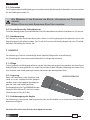
HYDRAULIC CUTTING TOOL
COUPE CABLE HYDRAULIQUE
HYDRAULISCHES SCHNEIDWERKZEUG
HERRAMIENTA HIDRAULICA DE CORTE
UTENSILE OLEODINAMICO DA TAGLIO
HT-TC051
OPERATION AND MAINTENANCE MANUAL
NOTICE D'UTILISATION ET ENTRETIEN
BEDIENUNGSANLEITUNG
MANUAL DE USO Y MANTENIMIENTO
MANUALE D'USO E MANUTENZIONE

2
1
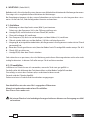
– Tool type
– Outil type
– Handwerkzeug Typ
– Herramienta tipo
– Tipo di utensile
– Year
– Année
– Jahr
– Año
– Anno
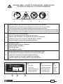
– Before using the tool, carefully read the instructions in this manual.
– Avant d'utiliser cet outil, lire attentivement les instructions de cette notice.
– Vor Inbetriebnahme unbedingt die Bedienungsanleitung durchlesen.
– Antes de utilizar la herramienta, leer atentamente las instrucciones contenidas en este manual.
– Prima di utilizzare l'utensile, leggere attentamente le istruzioni contenute in questo manuale.
– Keep hands clear of cutting blades.
– Au cours du coupage, tenir les mains loin des lames.
– Während des Schneidens, die Hände von den Messern fernhalten.
– Durante el corte, tener las manos alejadas de las cuchillas.
– Durante il taglio, tenere le mani lontane dalle lame.
2
– Do not cut steel.
– Ne pas couper l'acier et l'almélec.
– Keinen Stahl schneiden.
– No cortar acero.
– Non tagliare acciaio.
3
2
3
1
2 3
– Always wear safety glasses and gloves when operating this tool.
– Porter toujours les lunettes de protection et les gants de travail.
– Immer mit Schutzbrille und Handschuhen bedienen.
– Trabajar siempre con las gafas y guantes de seguridad.
– Operare sempre con visiera protettiva e guanti da lavoro.
4
12 3
1
4
– Max cutting diam.
– ø maxi de coupe
– Max. Schneid. ø
– ø max de corte
– ø max di taglio
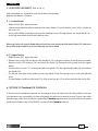
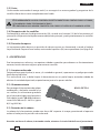
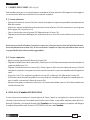
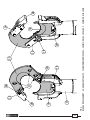
WARNING LABELS - ETIQUETTES SIGNALETIQUES - WARNSCHILDER
- ETIQUETAS DE ATENCION - ETICHETTE D'AVVERTENZA
TYPE
Ø MAX
50 mm
Made in Italy
HT-TC051
(
(
(
(
TG0351

3
ENGLISH
HYDRAULIC CUTTING TOOL
HT-TC051
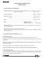
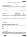
1. GENERAL CHARACTERISTICS
– Application range: the tool is suitable for cutting copper, aluminium or telephone cables having a
max. diameter of ........................................................................... 50 mm (2 in.)
– Rated operating pressure: ...............................................................................................600 bar (8,700 psi)
– Dimensions: lengt ...............................................................................................................497 mm (19.5 in.)
width ..............................................................................................................129 mm (5.1 in.)
– Weight: ..................................................................................................................................... 4,38 kg (9.6 lbs)
– Oil: .............................................................................................. ENI ARNICA ISO 32 or
SHELL TELLUS S2 V 32 or equivalent
– Advancing speed: the tool automatically switches from a fast advancing speed of blades to a
slower cutting speed.
– Safety: the tool is provided with max pressure valve; MPC1 special manometer, is available upon
request to check the proper setting of the valve.
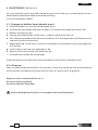
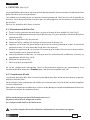
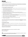
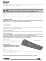
2. INSTRUCTIONS FOR USE (Ref. to Fig. 1)
2.1) Setting
Insert the cable between the blades at the desired cutting point.
For a running cable, press latch (28) and open the upper blade assembly.
Warning: the opening of upper blade assembly must be done when the tool is in rest position, with
the lower blade (18) completely retracted.
With the cable on the lower blade (18), close the upper blade assembly and secure the latch (28).
Before commencing the cutting operation ensure that the latch is fully secured: partial closure may
damage the tool head.
2.2) Blade advancement
Operate moveable handle (44) for lower blade advancement. This fi rst stage rapidly closes the
lower blade to the conductor. Make sure that blades (18 and 23) are exactly positioned on desired
cutting point, otherwise re-open blades following instructions as § 2.4 and re-position the cable.

4
ENGLISH
CANVAS BAG
2.3) Cutting
Continue operating the moveable handle, the lower blade advances gradually until the cable is
fully cut.
THE TOOL IS DESIGNED FOR CUTTING COPPER, ALUMINIUM AND TELEPHONE CABLES:
DO NOT ATTEMPT TO CUT STEEL OR ACSR CONDUCTORS.
2.4) Blade opening
Press the pressure release lever (58) for the rapid retraction of the ram and subsequent blade (18)
opening.
2.5) Rest setting
After completion of the work, press the release lever (58) to release the oil pressure (refer § 2.4).
3. WARNING
The tool is robust and requires very little daily maintenance.
Compliance with the following points, should help to maintain the optimum performance of the tool:
3.1) Accurate cleaning
Dust, sand and dirt are a danger for any hydraulic device.
Every day, after use, the tool must be cleaned with a clean cloth, taking care to remove any residual,
especially close to pin and moveable parts.
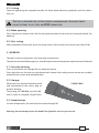
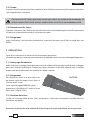
3.2) Storage
When not in use, the tool should be stored
and transported in the canvas bag, to
prevent damage.
Canvas bag: ref. CVB-010; size 545x160
mm (21.4x6.3 in.); weight 0,15 kg (0.33 lbs).
3.3) Head rotation
For ease of operation, the tool head can rotate through 90°.
Warning: do not attempt to turn the head if the hydraulic circuit is pressurised.

5
ENGLISH
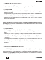
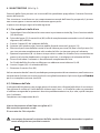
4. MAINTENANCE (Ref. to Fig. 2)
Air in the hydraulic circuit may aff ect the performance of the tool; e.g: no advancement or slow
advancement of the lower blade; lower blade pulsating.
In this case proceed as follows:
4.1) To purge air bubbles from hydraulic circuit
a – Hold tool upright in a vice with handles open (Fig. 2).
b – Unscrew the main handle (03) from the body (12) to expose the rubber oil reservoir (02).
c – Remove reservoir cap (01).
d – Operate moveable handle, several times, in order to advance the ram (14).
e – Press the pressure release lever (58) to retract the ram (14), discharge oil pressure from the circuit
and return all oil to the reservoir.
f – Repeat points (d - e) fi ve times, to ensure all air bubbles in the hydraulic circuit are purged into
the reservoir.
g – If the oil level is low, top up as directed in § 4.2.
h – Remove all air from reservoir (02) and fi t cap (01).
i – Assemble main handle (03) to tool body.
If the tool continues to malfunction return the tool for service/repair as detailed in § 6.
4.2) Oil top up
Every six months check the oil level in the reservoir. If necessary, top up the oil level to the top lip
of the reservoir and remove all air from reservoir, see § 4.1, points a, b, c, e, g, h and i.
Always use clean recommended oil, see § 1.
Do not use old or recycled oil.
Do not use hydraulic brake fl uid.
Ensure that disposal of used oil, is in accordance with current legislation.

6
ENGLISH
5. BLADE REPLACEMENT (Ref. to Fig. 3)
After extended use, the blades may loose their cutting edge.
Replace the blades as follows:
5.1) Lower blade
– Release latch (28), open the head.
– Operate moveable handle to advance the lower blade (18) until holding screw (29) is visible on
the ram (14).
– Using a fl at blade, screwdriver remove the holding screw (29) and release the lower blade (18).
– Insert the new blade and fi t the holding screw.
Warning: before closing the head release the oil pressure and retract the lower blade (18), otherwise
the tool head assembly may hit and damage the lower blade.
5.2) Upper blade
– Release latch (28), open the head .
– Remove the circlip (20) and extract the head pin (19), enough to release the tool head assembly.
– Remove circlip (25) and pin (26), to release the latch (28). Remove latch spring from the upper
blade.
– Unscrew the 4 screws (21), remove the left hand guide (22), the right hand guide (24) and release
the blade (23).
– Fit the left and right hand guides to the new blade. Place the spring into its seat and refi t the
latch.
– Fit the blade assembly to the head (13), fully insert the pin (19) and secure with the circlip (20).
6. RETURN TO Cembre FOR OVERHAUL
In the case of a breakdown contact our Area Agent who will advise you on the problem and give
you the necessary instructions on how to dispatch the tool to our nearest service Centre; if possible,
attach a copy of the Test Certifi cate supplied by Cembre together with the tool or fi ll in and attach
the form available in the “ASSISTANCE” section of the Cembre website.

7
ENGLISH
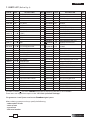
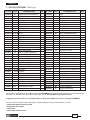
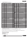
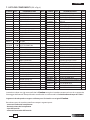
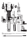
7. PARTS LIST (Ref. to Fig. 4)
The items marked ( ) are those Cembre recommends replacing if the tool is disassembled.
These items are supplied on request in the “HT-TC051 Spare Parts Package”.
The guarantee is void if parts used are not Cembre original spares.
When ordering spare parts always specify the following:
- code number of item
- name of item
- type of tool
- tool serial number
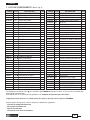
Code N° Item DESCRIPTION Qty Code N° Item DESCRIPTION Qty
6800040 01 RESERVOIR CAP 1
6720050 02 OIL RESERVOIR 1
6480055 03 MAIN HANDLE 1
6360250 04 O-RING 1
6740100 05 5/32" BALL 1
6520160 06 SUCTION SPRING 1
6740020 07 1/4" BALL 1
6520200 08 SPRING 1
6340590 09 BALL POSITIONING DOWEL 1
6360270 10 O-RING 1
6040181 11 BACK-UP RING 1
6160027 12 BODY 1
6860101 13 HEAD 1
6620171 14 RAM 1
6361810 15 SEAL 1
6641020 16 M 6 COPPER WASHER 1
6900334 17 M 6x30 SCREW 1
6420231 18 LOWER BLADE 1
6560691 19 UPPER BLADE PIN 1
6040421 20 Ø 10 CIRCLIP 1
6900315 21 M 6x16 SCREW 4
6370141 22 LEFT GUIDE 1
6420241 23 UPPER BLADE 1
6370151 24 RIGHT GUIDE 1
6700140 25 CIRCLIP 1
6560701 26 LATCH PIN 1
6520460 27 SPRING 1
6200051 28 LATCH 1
6370250 29 BLADE HOLDING SCREW 1
6080051 30 RAM BUSHING 1
6522314 31 BLADE RETURN SPRING 1
6360266 32 O-RING 1
6360161 33 O-RING 1
6560262 34 MOVABLE HANDLE PIN 2
6700060 35 CIRCLIP 4
6040101 36 BACK-UP RING 1
6362020 37 SEAL 1
6620090 38 PUMPING RAM 1
6360240 39 O-RING 1
6340590 40 BALL POSITIONING DOWEL 1
6520200 41 SPRING 1
6740020 42 1/4" BALL 1
6232000 43 LABEL (TG. 0351) 1
6480909 44 MOVEABLE HANDLE 1
6380200 45 HANDLE GRIP 1
6895020 46 MAX PRESSURE VALVE 1
6040080 47 BACK-UP RING 1
6360140 48 O-RING 1
6020027 49 PRESSURE RELEASE PIN 1
6600020 50 SPRING LOADED PIN 1
6520280 51 SPRING 1
6360120 52 O-RING 1
6740120 53 7/32" BALL 1
6600100 54 BALL SUPPORT 1
6520520 55 SPRING 1
6360166 56 O-RING 1
6900341 57 M 8x10 SCREW 1
6440100 58 PRESSURE RELEASE LEVER 1
6760100 59 ø 3x16 SPLIT PIN 1
6232303 60 METAL LABEL (TG. 0503) 1
6650118 61 RIVET ø 2,5x3,5 2
6635011 62 PRESSURE RELEASE PIN 1
6520861 63 SPRING 1
6340720 64 PRESSURE RELEASE DOWEL 1
6520160 65 S UCTION SPRING 1
6740100 66 5/32" BALL 1
6641020 67 M 6 COPPER WASHER 1
6900601 68 SUCTION SCREW 1
6860131 HEAD ASSEMBLY
6780271 COMPLETE RAM
6000088 SPARE PARTS PACKAGE

8
FRANÇAIS
COUPE-CABLE HYDRAULIQUE
TYPEHT-TC051
1. CARACTERISTIQUES GENERALES
– Domaine d'application: conçu pour sectionner des câbles en cuivre ou aluminium d'un diamètre
extérieur maximum de ..................................................... 50 mm (2 in.)
– Pression nominale:..............................................................................................................600 bar (8,700 psi)
– Dimensions: hauteur .......................................................................................................... 497 mm (19.5 in.)
largeur............................................................................................................129 mm (5.1 in.)
– Poids: ........................................................................................................................................4,38 kg (9.6 lbs)
– Huile: ......................................................................................... ENI ARNICA ISO 32 ou
SHELL TELLUS S2 V 32 ou équivalent
– Avance rapide: l'outil passe automatiquement de la vitesse rapide d'approche des lames, à la
vitesse lente de coupe.
– Sécurité: l'outil est pourvu d'une valve de surpression.
Pour vérifi er le bon fonctionnement de cette valve, un manomètre spécial, réf. MPC1, est dispo-
nible à la demande.
2. INSTRUCTIONS D'UTILISATION (Voir Fig. 1)
2.1) Mise en service
Positionner le conducteur entre les lames de l'outil à l'endroit souhaité pour la coupe.
Si le câble est passant, il sera alors nécessaire de tirer le loquet (28) de façon à ouvrir la tête (lame
supérieure).
Attention: ne jamais ouvrir la tête du coupe-câble tant que la lame inférieure (18) n'est pas com-
plètement descendue.
Positionner le câble sur la lame inférieure, et refermer la tête à l'aide du loquet (28).
Avant de procéder à la coupe, s'assurer que le loquet (28) soit parfaitement enclenché.
2.2) Avance des lames
En actionnant le bras mobile (44), le piston se déplace en vitesse rapide jusqu'à ce que les lames
(18 et 23) soient en contact avec le conducteur. Si la position de coupe n'est pas bonne, desserrer
les lames (voir § 2.4) et repositionner le câble.

9
FRANÇAIS
SACOCHE
2.3) Coupe
En poursuivant la manœuvre du bras mobile, la lame inférieure monte jusqu'à ce que le conducteur
soit complètement sectionné.
CET OUTIL N'A ÉTÉ CONÇU QUE POUR COUPER DES CÂBLES EN CUIVRE OU EN ALUMINIUM, ET
NE DOIT JAMAIS ÊTRE UTILISÉ SUR DES CONDUCTEURS EN ACIER OU EN ALUMINIUM-ACIER.
2.4) Réouverture des lames
Appuyer sur le levier (58), situé sur le corps afi n d'activer la valve de décompression (49) et permettre
le retour de la lame inférieure dans sa position de repos.
2.5) Rangement
Après l'utilisation, l'outil doit être ramené dans sa position de repos (voir § 2.4), et rangé dans son
coff ret.
3. PRECAUTIONS
Cet outil est robuste et ne nécessite aucun entretien particulier.
Les recommandations suivantes sont néanmoins souhaitables pour lui assurer une longévité optimum:
3.1) Nettoyage élémentaire
Veiller à toujours protéger l'outil de la poussière, du sable et de la boue qui représentent un danger
pour tout système hydraulique. Chaque jour, après utilisation, il doit être nettoyé avec un chiff on
propre, tout particulièrement aux endroit des pièces mobiles.
3.2) Rangement
Afi n d'éviter les chocs et la poussière, il est
de bonne règle de ranger l'outil dans sa
sacoche après usage.
Cette sacoche (type CVB-010) a pour
dimensions 545x160 mm (21.4x6.3 in.) et un
poids de 0,15 kg (0.33 lbs).
3.3) Rotation de la tête
La tête de ce coupe-câble pivote à 90°, permettant à l'utilisateur de toujours travailler dans les
meilleures conditions.
Attention: ne jamais forcer la rotation de la tête lorsque le circuit hydraulique est sous pression.

10
FRANÇAIS
4. ENTRETIEN (Voir Fig. 2)
Le seul problème nécessitant une intervention qui peut parfois être rencontré est la présence d'une
bulle d'air dans le circuit hydraulique.
Cet incident est caractérisé par un mauvais fonctionnement de l'outil au cours de la montée en
pression: soit la lame inférieure ne monte pas, soit elle progresse très lentement, soit elle avance
par à-coups.
Dans ce cas, procéder de la façon suivante:
4.1) Elimination de bulles d'air
a – Serrer l'outil en position verticale dans un étau et écarter le bras mobile (44) (voir Fig. 2).
b – Dévisser complètement le bras principal (03) du corps (12) pour accéder au réservoir d'huile en
caoutchouc (02).
c – Retirer le capuchon (01) du réservoir.
d – Actionner le bras mobile (44) de façon à faire avancer le piston (14).
e – Appuyer sur le levier (58) pour libérer la pression du circuit hydraulique jusqu'à la rètraction
totale du piston (14) et le retour de l'huile dans son réservoir.
f – Réitérer les opérations (d - e) au moins 5 fois pour que les bulles d'air du circuit soient entière-
ment évacuées par le réservoir d'huile.
g – Avant de refermer le réservoir, s'assurer que tout l'air ait été évacué, et eff ectuer, si besoin, un
complément d'huile (voir § 4.2).
h – Refermer le capuchon (01).
i – Revisser le bras principal (03).
Au cas où, malgré cette intervention, l'outil ne fonctionnerait toujours pas correctement, il est
recommandé de le retourner à Cembre pour une révision complète (voir § 6).
4.2) Complément d'huile
La présence de bulles d'air dans le circuit hydraulique peut être évitée en maintenant en perma-
nence le réservoir plein.
Par conséquent, nous préconisons de vérifi er son niveau au moins tous les 6 mois, et de le compléter
si cela est nécessaire.
Pour ce faire, se reporter aux indications ci-dessus: a, b, c , d et e, puis remplir complètement le réservoir.
Terminer ensuite par les opérations h et i.
Utiliser exclusivement un type d'huile mentionné au § 1.
Ne jamais utiliser d'huile usagée ou recyclée.
Il est indispensable d'utiliser de l'huile neuve.
Les huiles usagées doivent être éliminées conformément aux normes en vigueur.

11
FRANÇAIS
5. CHANGEMENT DES LAMES (Voir Fig. 3)
Il peut arriver qu' après une utilisation prolongée ou inappropriée des lames soient élimées ou
endommagées. Leur changement est très simple:
5.1) Lame inférieure
– Ouvrir la la partie supérieure de la tête à l'aide du loquet (28), jusqu’à la butée.
– Actionner le bras mobile (44) pour faire avancer la lame inférieure (18) jusqu’à ce que la vis de
fi xation (29) sur le piston (14) soit visible.
– Avec un tournevis, dévisser la vis (29) pour libérer la lame (18).
– Retirer l'ancienne lame de son logement, la remplacer par la nouvelle, et serrer le tout avec la vis.
Attention: avant de refermer la lame supérieure, relâcher la pression d’huile, de façon à ce que la
lame inférieure redescende complètement, pour éviter qu’elle soit heurtée et endommagée par la
supérieure.
5.2) Lame supérieure
– Ouvrir la tête à l'aide du loquet (28) jusqu'à la butée.
– Retirer l’anneau élastique (20), et extraire partiellement l'axe (19) de façon à libérer la partie su-
périeure de la tête.
– Retirer l’anneau élastique (25), extraire l'axe (26), dégager le loquet (28), et récupérer le ressort
situé dans son logement.
– Démonter les 4 vis (21), retirer le guide gauche (22), et le guide droit (24) de façon à libérer la
lame (23).
– Fixer les guides sur la lame neuve, repositionner le ressort dans son logement, et remonter le lo-
quet (28).
– Repositionner l'ensemble ainsi reconstitué sur la tête (13), introduire l'axe (19), et bloquer le tout
avec l'anneau élastique (20).
6. ENVOI EN REVISION A Cembre
En cas de dysfonctionnement de l’appareil, merci de vous adresser à notre Agent Régional qui vous
conseillera et le cas échéant vous donnera les instructions nécessaires pour envoyer l’appareil à
notre Centre de Service le plus proche. Dans ce cas, joindre une copie du Certifi cat d’Essai livré par
Cembre avec l’appareil ou remplir et joindre le formulaire disponible dans la section “ASSISTANCE”
du site web Cembre.

12
6362020 37 JOINT 1
6620090 38 PISTON DE POMPAGE 1
6360240 39 JOINT 1
6340590 40 AXE DE BILLE 1
6520200 41 RESSORT 1
6740020 42 BILLE 1/4" 1
6232000 43 ETIQUETTE (TG. 0351) 1
6480909 44 BRAS MOBILE 1
6380200 45 POIGNEE 1
6895020 46 VALVE DE SURPRESSION 1
6040080 47 ANNEAU TEFLON 1
6360140 48 JOINT 1
6020027 49 PISTON DE DECOMPRESSION 1
6600020 50 AXE DE RAPPEL LEVIER 1
6520280 51 RESSORT 1
6360120 52 JOINT 1
6740120 53 BILLE 7/32" 1
6600100 54 SUPPORT DE BILLE 1
6520520 55 RESSORT 1
6360166 56 JOINT 1
6900341 57 VIS M8x10 1
6440100 58 LEVIER DE DECOMPRESSION 1
6760100 59 GOUPILLE ø 3x16 1
6232303 60 PLAQUETTE (TG. 0503) 1
6650118 61 RIVET ø 2,5x3,5 2
6635011 62 SOMMET DE DECOMPRESSION 1
6520861 63 RESSORT DE DECOMPRESSION 1
6340720 64 GOUPILLE DE DECOMPRESSION 1
6520160 65 RESSORT 1
6740100 66 BILLE 5/32" 1
6641020 67 RONDELLE DE CUIVRE M6 1
6900601 68 VIS DE ASPIRATION 1
6860131 TETE COMPLETE
6780271 PISTON COMPLET
6000088 PAQUET RECHANGE
FRANÇAIS
Les éléments accompagnés d’un ( ) sont ceux que Cembre recommande de remplacer en cas de démontage
de l’outil. Ces éléments sont fournis sur demande dans le “Paquet Rechange pour HT-TC051.
La garantie perd tout eff et en cas d'emploi de pièces détachées diff érentes des pièces d'origine Cembre.
Lors de la commande de pièces détachées, veuillez indiquer toujours les éléments suivants:
- numéro de code article de la pièce
- désignation de la pièce
- type d'outil
- numéro de série de l'outil
7. PIECES DETACHEES (Voir Fig. 4)
N° Code
Pièce DENOMINATION Q.té
N° Code Pièce DENOMINATION Q.té
6800040 01 CAPUCHON DE RESERVOIR 1
6720050 02 RESERVOIR 1
6480055 03 BRAS PRINCIPAL 1
6360250 04 JOINT 1
6740100 05 BILLE 5/32" 1
6520160 06 RESSORT 1
6740020 07 BILLE 1/4" 1
6520200 08 RESSORT 1
6340590 09 AXE DE BILLE 1
6360270 10 JOINT 1
6040181 11 ANNEAU TEFLON 1
6160027 12 CORPS 1
6860101 13 TETE 1
6620171 14 PISTON 1
6361810 15 JOINT 1
6641020 16 RONDELLE DE CUIVRE M6 1
6900334 17 VIS M6x30 1
6420231 18 LAME INFERIEURE 1
6560691 19 AXE DE LAME SUPERIEUR 1
6040421 20 ANNEAU ELASTIQUE Ø 10 1
6900315 21 VIS M 6x16 4
6370141 22 GUIDE GAUCHE 1
6420241 23 LAME SUPERIEURE 1
6370151 24 GUIDE DROIT 1
6700140 25 ANNEAU ELASTIQUE 1
6560701 26 AXE DE LOQUET 1
6520460 27 RESSORT 1
6200051 28
LOQUET 1
6370250 29
VIS DE FIXATION LAME INFERIEURE
1
6080051 30 ANNEAU GUIDE PISTON 1
6522314 31 RESSORT 1
6360266 32 JOINT 1
6360161 33 JOINT 1
6560262 34 AXE BRAS MOBILE 2
6700060 35 ANNEAU ELASTIQUE 4
6040101 36 ANNEAU TEFLON 1

13
DEUTSCH
HYDRAULISCHES SCHNEIDWERKZEUG
TYP HT-TC051
1. ALLGEMEINE EIGENSCHAFTEN
– Anwendungsbereich: Geeignet zum Schneiden von Kupfer-, Aluminium- und Telefonkabeln mit
einem max. Durchmesser von ............................................ 50 mm (2 in.)
– Arbeitsdruck: .........................................................................................................................600 bar (8,700 psi)
– Abmasse: Länge ................................................................................................................... 497 mm (19.5 in.)
Breite ....................................................................................................................129 mm (5.1 in.)
– Gewicht: ..................................................................................................................................4,38 kg (9.6 lbs)
– Hydrauliköl: ........................................................................... ENI ARNICA ISO 32 oder
SHELL TELLUS S2 V 32 oder ähnlich
– Eilvorschub: Das Werkzeug ist mit einer Doppelkolbenhydraulik ausgerüstet, die an fang ein
schnelles Zusammenfahren der Schneidmesser ermöglicht, und dann auto matisch auf den lang-
sameren Arbeitshub umschaltet.
– Sicherheit: Das Werkzeug ist mit einem Überdruckventil ausgestattet. Der Arbeitsdruck kann mit
dem Messgerät MPC1, das auf Anfrage lieferbar ist, gemessen werden.
2. BEDIENUNGSHINWEISE (Siehe Bild 1)
2.1) Vorbereitung
Den zu schneidenden Leiter zwischen den Schneidmessern positionieren.
Bei einem durchgehenden Leiter muß das Gegenmesser durch die Betätigen der Verriegelung (28)
geöff net werden, so daß sich der Befestigungsbolzen (19) dreht.
Achtung: Die Öff nung des Gegenmessers darf nur mit ganz zurückgefahrenem Schneidmesser (18)
erfolgen.
Das Kabel an das Schneidmesser (18) anlegen und das Gegenmesser mit der Verriegelung (28)
schließen.
Vor dem Schneiden kontrollieren, daß die Verriegelung (28) einwandfrei eingerastet ist.
2.2) Schneidvorgang
Mit Pumpen des Pumparms (44) näheren sich den Schneidmesser.
Bein Pumpen fährt der Kolben schnell vor, und bringt die Schneidmesser gegen das Kabel. Feststellen
das sich die Schneidmesser (18 und 23) im gewünschten Schneidpunkt befi nden; im zweifelsfall sie
wieder öff nen (siehe Punkt 2.4) und es kann neu positioniert werden.

14
DEUTSCH
SEGELTUCHTASCHE
2.3) Schneiden
Den Pumparm gleichmäßig betätigen um ein konstantes Vorfahren des Schneidmessers zu erreichen
bis das Kabel geschnitten ist.
DAS WERKZEUG IST ZUM SCHNEIDEN VON KUPFER-, ALLUMINIUM UND TELEFONKABELN
GEEIGNET.
NIEMALS STAHLSEILE ODER ALUMUNIUM-STAHL SEILE SCHNEIDEN.
2.4) Zurückfahren des Schneidmesser
Durch das Betätigen des Druckablaßhebels (58) fährt der Kolben mit dem Schneidmesser (18) zurück .
2.5) Nachbereitung
Das Werkzeug sollte nach Beendigung der Arbeit in die Ausgangsposition gebracht und in die
Verpackungseinheit gelegt werden. Der Druck muß vorher vollständig abgelassen sein (Druckab-
laßhebel (58) betätigen) siehe § 2.4.
3. HINWEISE
Das Werkzeug ist robust und benötigt keine spezielle Pfl ege oder Instandhaltung.
Zur Erhaltung der Garantieansprüche beachten Sie folgende Hinweise:
3.1) Pfl ege
Dieses hydraulische Werkzeug sollte vor starker Verschmutzung geschützt werden, da diese für ein
hydraulisches System gefährlich ist. Jeden Tag nach der Arbeit sollte das Werkzeug mit einem Tuch
von Schmutz und Staub gereinigt werden; besonders die beweglichen Teile.
3.2) Lagerung
Wenn das Werkzeug nicht benötigt wird,
sollte es in der Segeltuchtasche gelagert
werden, und ist somit gegen Beschädigun-
gen wie Stoß und Staub geschützt.
Die Segeltuchtasche (Typ CVB-010) hat die
Abmasse 545x160 mm (21.4x6.3 in.) und ein
Gewicht von 0,15 kg (0.33 lbs).
3.3) Drehbewegung des Kopfes
Das Werkzeug ist mit einem Kopf ausgerüstet, der um 90° drehbar ist und somit ein komfortables
Arbeiten ermöglicht.
Der Kopf sollte nicht unter Druck stehend gedreht werden.

15
DEUTSCH
4. WARTUNG (Siehe Bild 2)
Befi ndet sich Luft im Hydrauliksystem, kann es zum fehlerhaften Arbeiten des Werkzeuges kommen.
Dies zeigt sich in ungewöhnlichem Verhalten des Werkzeuges.
Bei Pumpbeginn bewegt sich das untere Schneidmesser nicht oder nur sehr langsam bzw. stoss-
weise. Ist dies der Fall, sind die folgenden Hinweise zu beachten:
4.1) Entlüften
a – Werkzeug mit dem Kopf nach unten (Bild 2) positionieren.
Dabei muss der Pumparm (44) in der Öff nungsstellung sein.
b – Handgriff (03) aufschrauben und vom Öltank (02) ziehen.
c – Ölverschlusskappe (01) entfernen.
d – Den Pumparm (44) drei vier mal betätigen und den Kolben (14) vorfahren.
e – Öldruck wieder ablassen und der Kolben (14) fährt vollständig zurück .
f – Vorgang (d - e ) einige Male wiederholen, bis die gesamte Luft ausgetreten ist oder sich im Öltank
gesammelt hat.
g – Bevor der Öltank geschlossen wird, kann bei Bedarf noch Öl nachgefüllt werden entspr. Pkt. 4.2.
h – Öltank (02) verschliessen.
i – Handgriff (03) über den Öltank schieben.
Sehr selten kann es passieren, dass das Werkzeug nach diesen Wartungsarbeiten nicht oder nicht
richtig funktioniert. In diesem Fall sollte entspr. Pkt. 6 verfahren werden.
4.2) Öl nachfüllen
Luftblasen im Öltank lassen sich vermeiden, wenn der Tank stets gut gefüllt ist.
Deshalb sollte alle 6 Monate der Tank kontrolliert und bei Bedarf aufgefüllt werden.
Dies erfolgt so wie in den Punkten a, b, c und e beschrieben wurde.
Danach wird der Öltank aufgefüllt.
Zuletzt wird wie in Punkt h und i beschrieben vorgegangen.
Zum Nachfüllen stets das unter Pkt.1 angegebene Öl benutzen.
Niemals mit gebrauchtem oder altem Öl nachfüllen.
Das Öl muss stets sauber sein.
Bei einem Ölwechsel sind unbedingt die vorgeschriebenen Normen zur Entsorgung von Altöl
zu beachten.

16
DEUTSCH
5. MESSERWECHSEL (Siehe Bild 3)
Sollten die Schneidmesser stumpf oder durch eine falsche Anwendung beschädigt sein, lassen sie
sich sehr leicht auswechseln:
5.1) Schneidmesser
– Kopf an der Verriegelung (28) öff nen.
– Den Pumparm betätigen und das Schneidmesser (18) nach vorne fahren, bis die Stiftschraube
(29) zur Befestigung des Messers auf dem Kolben (14) sichtbar ist.
– Die Stiftschraube (29) mit einem Schraubenzieher herausschrauben und das Schneidmesser (18)
auswechseln.
– Anschließend mit der Stiftschraube das neue Messer wieder befestigen.
Achtung: Bevor das Gegenmesser (18) wieder geschlossen wird, muss das Schneidmesser komplett
zurückgefahren sein, sonst könnten sich die o.g. Schneidmesser gegenseitig beschädigen.
5.2) Gegenmesser
– Den Kopf durch Betätigen der Verriegelung (28) öff nen.
– Den Federring (20) entfernen, und den Gelenkbolzen (19) herausziehen, so daß der Kopf abge-
nommen werden kann.
– Den Federring (25) lösen und den Bolzen (26) der Verriegelung (28) entfernen.
Die Feder auch aus dem Sitz entfernen.
– Die 4 Schrauben (21) der linken (22) und rechten (24) Führung lösen und Gegenmesser (23)
demontieren.
– Die linke und rechte Führung auf das neue Schneidmesser montieren, die Feder in den Sitz ein-
passen und die Verriegelung (28) erneut montieren.
– Das Schneidmesser auf dem Werkzeugkopf (13) befestigen und den Bolzen (19) mit dem Federring
(20) sichern.
6. EINSENDUNG AN Cembre ZUR ÜBERPRÜFUNG
Sollten an dem Gerät Fehler auftreten, wenden Sie sich bitte an unsere Gebietsvertretung, die
Sie gerne beraten und Ihnen alle nötigen Informationen zum Einsenden des Gerätes an unseren
Hauptsitz geben wird. Wenn vorhanden, legen Sie dem Gerät bitte eine Kopie des von Cembre
mitgelieferten Zertifi kates bei oder füllen das, unter dem Bereich “SUPPORT“ der Cembre Website,
verfügbare Formular aus und fügen es bei.

17
DEUTSCH
Die mit ( ) gekennzeichneten Bestandteile sind jene, welche Cembre auszuwechseln empfi ehlt, falls das Gerät
in seine Bestandteile zerlegt wird.
Genannte Einzelteile sind auf Anfrage in der “Ersatzteilpackung HT-TC051” erhältlich.
Die Garantie verfällt, wenn nicht Originalteile aus dem Hause Cembre in das Gerät eingebaut werden.
Geben Sie bei der Bestellung aller Ersatzteile folgende Informationen an:
- Codenummer des Ersatzteils
- Beschreibung des Ersatzteils
- Werkzeug Typ
- Seriennr. des Werkzeugs
7. ERSATZTEILLISTE (Siehe Bild 4)
Codenr. Teil BESCHREIBUNG
Menge
Codenr. Teil BESCHREIBUNG
Menge
6800040 01 ÖLTANKVERSCHLUß 1
6720050 02 ÖLTANK 1
6480055 03 HANDGRIFF 1
6360250 04 O-RING 1
6740100 05 KUGEL 5/32" 1
6520160 06 ANSAUGFEDER 1
6740020 07 KUGEL 1/4" 1
6520200 08 FEDER 1
6340590 09
KUGELPOSITIONIERUNGSSCHRAUBE
1
6360270 10 O-RING 1
6040181 11 STÜTZRING 1
6160027 12 GRUNDKÖRPER 1
6860101 13 KOPFE 1
6620171 14 KOLBEN 1
6361810 15 DICHTUNG 1
6641020 16 KUPFER SCHRAUBE M6 1
6900334 17 SCHRAUBE M6x30 1
6420231 18 SCHNEIDMESSER 1
6560691 19 BEFESTIGUNGSBOLZEN 1
6040421 20 FEDERRING Ø 10 1
6900315 21 SCHRAUBE M 6x16 4
6370141 22 LINKE FÜHRUNG 1
6420241 23 GEGENMESSER 1
6370151 24 RECHTE FÜHRUNG 1
6700140 25 FEDERRING 1
6560701 26 BOLZEN 1
6520460 27 FEDER 1
6200051 28 VERRIEGELUNG 1
6370250 29 STIFTSCHRAUBE 1
6080051 30 FÜHRUNGSBUCHSE 1
6522314 31 MESSERRÜCKZUGFEDER 1
6360266 32 O-RING 1
6360161 33 O-RING 1
6560262 34 BOLZEN 2
6700060 35 FEDERRING 4
6040101 36 STÜTZRING 1
6362020 37 DICHTUNG 1
6620090 38 PUMPKOLBEN 1
6360240 39 O-RING 1
6340590 40
KUGELPOSITIONIERUNGSSCHRAUBE
1
6520200 41 FEDER 1
6740020 42 KUGEL 1/4" 1
6232000 43 AUFKLEBER (TG. 0351) 1
6480909 44 PUMPARM 1
6380200 45 HANDGRIFF 1
6895020 46 ÜBERDRUCKVENTIL 1
6040080 47 STÜTZRING 1
6360140 48 O-RING 1
6020027 49 DRUCKABLAßKOLBEN 1
6600020 50 FEDER DRUCKABLAßHEBEL 1
6520280 51 FEDER 1
6360120 52 O-RING 1
6740120 53 KUGEL 7/32" 1
6600100 54 KUGELHALTERUNG 1
6520520 55 FEDER 1
6360166 56 O-RING 1
6900341 57 SCHRAUBE M8x10 1
6440100 58 DRUCKABLAßHEBEL 1
6760100 59 FEDERSTIFT ø 3x16 1
6232303 60 TYPENSCHILD (TG. 0503) 1
6650118 61 NIET ø 2,5 x 3,5 2
6635011 62 DRUCKABLAßSTIFT 1
6520861 63 FEDER 1
6340720 64 DRUCKABLAßPAßTIFT 1
6520160 65 ANSAUGFEDER 1
6740100 66 KUGEL 5/32" 1
6641020 67 KUPFER SCHEIBE M6 1
6900601 68 ANSAUGSCHRAUBE 1
6860131 KOMPLETTER KOPF
6780271 VORMONTIERTER KOLBEN
6000088 ERSATZTEILPACKUNG

18
ESPAÑOL
HERRAMIENTA HIDRAULICA DE CORTE
TIPO HT-TC051
1. CARACTERISTICAS GENERALES
– Campo de aplicación: idóneo para cortar cables de cobre, aluminio así como de telecomunica-
ciones con ø max. de ............................................................. 50 mm (2 in.)
– Presión nominal de trabajo: ........................................................................................... 600 bar (8,700 psi)
– Dimensiones: longitud ....................................................................................................... 497 mm (19.5 in.)
anchura ........................................................................................................ 129 mm (5.1 in.)
– Peso: ...........................................................................................................................................4,38 kg (9.6 lbs)
– .Aceites recomendados: .................................................... ENI ARNICA ISO 32 o bien
SHELL TELLUS S2 V 32 o equivalentes
– Velocidad de avance: son dos: una rápida de aproximación de las cuchillas y otra más leta de
corte. El paso de una a otra velocidad es automático.
– Seguridad: la herramienta esta provista de una válvula de seguridad con la que la presión correcta
es verifi cable mediante el instrumento adecuado MPC1 disponible mediante pedido.
2. INSTRUCCIONES DE USO (Ref. a Fig. 1)
2.1) Preparación
Colocar el cable entre las cuchillas de manera que éstas se encuentren en el punto de corte deseado.
Si el cable es pasante, será necesario abrir el grupo superior apretando el diente de retención (28)
y haciéndola girar alrededor de su perno de sujeción (19).
Atención: solamente se puede abrir el grupo superior cuando la cuchilla inferior (18) se encuentre
completamente retraída.
Apoyar la cuchilla inferior (18) contra el cable que se quiere cortar, volver a cerrar el grupo superior
enganchando el diente de retención (28).
Antes de proceder con la operación de corte, comprobar que el diente de retención (28) esté en-
ganchado perfectamente.
2.2) Acercamiento de las cuchillas
Maniobrando el mango móvil (44), se inicia el acercamiento de las cuchillas. Durante esta fase, el
pistón avanza hasta que las dos cuchillas (18 y 23) choquen a tope contra el cable. Comprobar que
las cuchillas se encuentran exactamente enfrente del punto que se quiere cortar; de no ser así,
volverlas a abrir (véase punto 2.4) y volverlas a colocar.

19
ESPAÑOL
BOLSA DE TELA
2.3) Corte
Continuando accionando el mango móvil, se conseguirá un avance gradual y progresivo de la
cuchilla inferior hasta cortar completamente el cable.
ESTA HERRAMIENTA HA SIDO CONCEBIDA ESPECÍFICAMENTE PAR A CORTAR CABLES DE COBRE,
DE ALUMINIO O PARA TELECOMUNICACIONES.
N
O EMPLEARLA BAJO NINGÚN CONCEPTO CON CABLES DE ACERO O DE ALUMINIO-ACERO.
2.4) Reapertura de las cuchillas
Presionando la palanca de despresurización (58), situada en el cuerpo (13) de la herramienta, el
pistoncillo (49) permitirá el rápido retroceso del pistón principal, y consiguientemente, las cuchillas
se separarán.
2.5) Posición de reposo
La herramienta debe dejarse en posición de descanso para ser almacenada, cuando el trabajo
haya fi nalizado. Depresurice el aceite, accionando la palanca (58) correspondiente (ver Epigr. 2.4).
3. ADVERTENCIAS
Esta herramienta es robusta y no requiere cuidados especiales para obtener un funcionamiento
correcto, bastára observar algunas precauciones sencillas:
3.1) Limpieza adecuada
Tenga presente que el polvo, la arena y la suciedad en general, rapresentan un peligro para toda
herramienta hidráulica.
Tras cada día de uso, se debe limpiar la herramienta con un paño limpio, teniendo cuidado de
eliminar la suciedad depositada, especialmente junto a las partes móviles.
3.2) Almacenamiento
Para proteger la herramienta de golpes
accidentales y del polvo cuando no se
va a utilizar, es conveniente guardarla
en su bolsa de tela de cierre hermético.
Dicha bolsa (mod. CVB-010) de dimen-
siones 545x160 mm (21.4x6.3 in.) y pesa
0,15 kg (0.33 lbs).
3.3) Rotación de la cabeza
La cabeza de la herramienta puede rotar hasta 90° respecto al cuerpo, permitiendo al operario
realizar el trabajo en la posición más adecuada.
Atención: no fuerce la cabeza, intentando rotarla, mientras el circuito hidráulico esté presurizado.

20
ESPAÑOL
4. MANTENIMIENTO (Ref. a Fig. 2)
Las burbujas de aire en el circuito del aceite pueden causar un funcionamiento incorrecto de la he-
rramienta. Tal situación se manifesta con un funcionamiento anormal de la herramienta: al bombear,
el pistón no avanza, o bien se mueve muy lentamente ó vibra.
En este caso se debe actuar del modo siguiente:
4.1) Para expulsar las burbujas de aire
a – Fije la herramienta verticalmente, con la cabeza hacia abajo, manteniendo el mango móvil (44)
separado completamente (ver. Fig. 2).
b – Desenrosque el mango fi jo (03) del cuerpo (12) y sáquelo, deslizándolo, descubriendo el depósito
de aceite de reserva (02) de caucho.
c – Quite el tapón (01) del depósito de caucho.
d – Bombée con el mango móvil, unas 3 o 4 veces, hasta que el pistón (14) avance.
e – Presionando la palanca de despresurización (58), el pistón (14) retrocede completamente y el
aceite regresa al depósito de reserva.
f – Repita las operaciones (d - e) al menos 5 veces, a fi n de que las burbujas de aire del circuito hi-
dráulico sean expulsadas y se extraigan del depósito del aceite.
g – Antes de volver a cerrar el depósito se debe eliminar el aire. Si el nivel de aceite fuese bajo,
efectúe su rellenado como se indica en el epig. 4.2.
h – Vuelva a enroscar el tapón (01) del depósito de aceite de reserva (02).
i – Coloque el mango fi jo (03).
En caso de que la herramienta, incluso después de esta operaciones de mantenimiento, no funcio-
nase correctamente (el pistón no avanza o vibra) es aconsejable llevarla a Cembre para su revisión
completa (ver Epig. 6).
4.2) Rellenado de aceite
El depósito del aceite debe estar siempre lleno; lo cual evitará que se formen burbujas de aire en
su interior.
Se aconseja verifi car el nivel de aceite, al menos cada 6 meses, si el nivel fuese bajo, proceda al
rellenado, realizando las operaciones descritas anteriormente, en los puntos a, b, c y e, por último
rellene hasta el borde del depósito.
Complete con las operaciones h y i.
Use exclusivamente uno de los tipos de aceite recomendados en el Epig. 1.
No use nunca aceite usado.
Debe ser aceite limpio.
En caso de un eventual cambio de aceite, deposite el aceite usado, respetando escrupulosa-
mente la legislación especifi ca respecto a la materia.

21
ESPAÑOL
5. CAMBIO DE LAS CUCHILLAS (Ref. a Fig. 3)
Puede suceder que las cuchillas se estropeen tras un uso prolongado o impropio.
Para efectuar el cambio de las cuchillas, actúe como sigue:
5.1) Cuchilla inferior
– Abrir la cabeza desenganchando el diente de retención (28) y hacer girar completamente el grupo
superior, hasta el tope.
– Accionar el mango móvil (44) para hacer avanzar la cuchilla inferior (18) hasta que quede visible
el tornillo de sujección (29) de la misma sobre el pistón (14).
– Con un destornillador, desenroscar el tornillo (29) y soltar así la cuchilla (18).
– Sacar la cuchilla vieja del alojamiento correspondiente del pistón, colocar la nueva y sujetarla
con el tornillo mencionado.
Atención: antes de volver a cerrar el grupo superior, evacuar la presión del aceite haciendo retroceder
completamente la cuchilla (18); en caso contrario, el grupo superior podría chocar contra la arista
de la cuchilla inferior y estropearla.
5.2) Cuchilla superior
– Abrir el grupo superior desenganchando el diente de retención (28).
– Quitar el aro (20), extraer el pasador (19) para soltar completamente el grupo superior de la
cabeza.
– Quitar el aro (25), extraer el pasador (26) y separar el diente de retención (28) del grupo superior.
Recuperar el muelle que quedará así liberado de su alojamiento.
– Destornillar los 4 tornillos (21) y quitar las guías de la izquierda (22) y de la derecha (24) liberando
la cuchilla (23).
– En la cuchilla nueva montar las guías de la izquierda y de la derecha, introducir en el asiento de
ésta el muelle y volver a montar el diente de retención (28).
– Montar el grupo superior en la cabeza (13), meter a fondo el pasador (19) y sujetarlo con el aro
elástico (20).
6. DEVOLUCION A Cembre PARA REVISIONES
En caso de fallo de la herramienta, contactar con nuestro Agente de Zona quien les aconsejará y
eventualmente les facilitará las instrucciones necesarias para remitir la herramienta a nuestro centro
de servicio más cercano. En tal caso, adjuntar a ser posible una copia del Certifi cado de Ensayo en-
tregado en su día por Cembre con la herramienta o completar y adjuntar el formulario disponible
en la sección “ASISTENCIA” del sitio web Cembre.

22
ESPAÑOL
7. LISTA DE COMPONENTES (Ref. a Fig. 4)
Los elementos indicados con ( ) son aquellos que Cembre aconseja cambiar en el caso de un posible des-
montaje de la herramienta.
Estos elementos se suministran bajo pedido en el “Paquete de Repuesto para HT-TC051”.
La garantía pierde efi cacia si se utilizan piezas de repuesto distintas de las originales Cembre.
Al pedir piezas de repuesto, indicar siempre los elementos siguientes:
- número de código del elemento
- descripción del elemento
- tipo de herramienta
- número de serie de la herramienta
N° Código
Elemento
DESCRIPCION
C.dad
N° Código
Elemento
DESCRIPCION
C.dad
6362020 37 JUNTA DE GOMA 1
6620090 38 PISTON BOMBEO 1
6360240 39 JUNTA DE GOMA 1
6340590 40 TORNILLO RETEN DE BOLA 1
6520200 41 MUELLE 1
6740020 42 BOLA 1/4" 1
6232000 43 ETIQUETA (TG. 0351) 1
6480909 44 MANGO MOVIL 1
6380200 45 EMPUÑADURA MANGO 1
6895020 46 VALVULA COMPLETA 1
6040080 47 ANILLA DE PLASTICO 1
6360140 48 JUNTA DE GOMA 1
6020027 49
PISTONCILLO DESBLOQ. PRESION
1
6600020 50 PERNO PALANCA 1
6520280 51 MUELLE 1
6360120 52 JUNTA DE GOMA 1
6740120 53 BOLA 7/32" 1
6600100 54 SOPORTE BOLA 1
6520520 55 MUELLE 1
6360166 56 JUNTA DE GOMA 1
6900341 57 TORNILLO M 8x10 1
6440100 58
PALANCA DESBLOQUEO PRESION
1
6760100 59 PASADOR ø 3x16 1
6232303 60 TARJETA (TG. 0503) 1
6650118 61 PASADOR ø 2,5x3,5 2
6635011 62
CONTERA DE DESCARGA PRESION
1
6520861 63 MUELLE 1
6340720 64
TORNILLO DE DESCARGA PRESION
1
6520160 65 MUELLE DE SUCCION 1
6740100 66 BOLA 5/32" 1
6641020 67 ARANDELA DE COBRE 1
6900601 68 VALVULA DE SUCCION 1
6860131 CABEZA COMPLETA
6780271 PISTON COMPLETO
6000088 PAQUETE DE REPUESTO
6800040 01 TAPON DEPOSITO ACEITE 1
6720050 02 DEPOSITO ACEITE 1
6480055 03 MANGO FIJO 1
6360250 04 JUNTA DE GOMA 1
6740100 05 BOLA 5/32" 1
6520160 06 MUELLE DE SUCCION 1
6740020 07 BOLA 1/4" 1
6520200 08 MUELLE 1
6340590 09 TORNILLO RETEN DE BOLA 1
6360270 10 JUNTA DE GOMA 1
6040181 11 ANILLA DE PLASTICO 1
6160027 12 CUERPO 1
6860101 13 CABEZA 1
6620171 14 PISTON 1
6361810 15 JUNTA DE GOMA 1
6641020 16 ARANDELA DE COBRE M6 1
6900334 17 TORNILLO M 6x30 1
6420231 18 CUCHILLA INFERIOR 1
6560691 19
PASADOR BLOQUEO CUCHILLA SUP.
1
6040421 20 ARO ELASTICO Ø 10 1
6900315 21 TORNILLO M 6x16 4
6370141 22 GUIA IZQUIERDA 1
6420241 23 CUCHILLA SUPERIOR 1
6370151 24 GUIA DERECHA 1
6700140 25 ARO ELASTICO 1
6560701 26 PERNO 1
6520460 27 MUELLE 1
6200051 28 DIENTE DE RETENCION 1
6370250 29 TORNILLO CUCHILLA INFERIOR 1
6080051 30 CASQUILLO DE GUIA 1
6522314 31 MUELLE RETORNO CUCHILLA 1
6360266 32 JUNTA DE GOMA 1
6360161 33 JUNTA DE GOMA 1
6560262 34 PERNO MANGO MOVIL 2
6700060 35 ARO ELASTICO 4
6040101 36 ANILLA DE PLASTICO 1

23
UTENSILE OLEODINAMICO TRANCIACAVI
TIPO HT-TC051
1. CARATTERISTICHE GENERALI
– Campo di applicazione: adatto ad eseguire il taglio di cavi in rame, alluminio o cavi telefonici
con Ø esterno max. di .......................................................50 mm (2 in.)
– Pressione nominale di esercizio: ................................................................................... 600 bar (8,700 psi)
– Dimensioni: lunghezza ...................................................................................................... 497 mm (19.5 in.)
larghezza (manico mobile bloccato) ...................................................129 mm (5.1 in.)
– Peso: ..........................................................................................................................................4,38 kg (9.6 lbs)
– Olio consigliato: ................................................................... ENI ARNICA ISO 32 oppure
SHELL TELLUS S2 V 32 o equivalenti
– Velocità di avanzamento: sono due: una rapida di avvicinamento delle lame ed una più lenta di
taglio. La commutazione da una all’altra velocità é automatica.
– Sicurezza: l'utensile è munito di valvola di massima pressione la cui corretta taratura è verifi cabile
mediante l'apposito strumento MPC1 fornibile a richiesta.
2. ISTRUZIONI PER L’USO
2.1) Preparazione (Rif. a Fig. 1)
Posizionare il cavo tra le lame in modo che queste si trovino in corrispondenza col punto di taglio
desiderato. Se il cavo è passante, sarà necessario aprire il complesso superiore sganciando il dente
di arresto (28) e facendolo ruotare attorno al proprio perno (19).
Attenzione: l'apertura del complesso superiore dovrà essere eff ettuata solamente a lama inferiore
(18) completamente retratta.
Appoggiare la lama inferiore (18) al cavo da tagliare, richiudere il complesso superiore bloccandolo
col dente di arresto (28).
Prima di procedere con l'operazione di taglio assicurarsi che il dente di arresto (28) sia perfettamente
agganciato.
2.2) Accostamento delle lame
Azionando il manico mobile (44), inizia l'avvicinamento della lama inferiore.
Durante questa fase il pistone avanza velocemente portando in battuta le due lame (18 e 23) contro
il cavo. Assicurarsi che le lame si trovino esattamente in corrispondenza col punto da tagliare; in
caso contrario riaprirle (vedi punto 2.4) e riposizionarle.
ITALIANO

24
2.3) Taglio
Continuando ad azionare il manico mobile si avrà un avanzamento graduale e progressivo della
lama inferiore fi no al completo taglio del cavo.
QUESTO UTENSILE È SPECIFICATAMENTE PROGETTATO PER IL TAGLIO DI CAVI IN RAME O ALLU-
MINIO;
N
ON UTILIZZARLO ASSOLUTAMENTE SU CORDE IN ACCIAIO O ALLUMINIO-ACCIAIO.
2.4) Riapertura delle lame
Per riaprire le lame premere a fondo la leva di sblocco pressione (58) posta sul corpo pompante
dell'utensile; si azionerà così il pistoncino di sblocco pressione olio (49) che provocherà la riapertura
della lama inferiore fi no al suo arresto nella posizione iniziale di riposo (completamente retratta).
2.5) Messa a riposo
A lavoro ultimato, prima di riporre l'utensile nella sua custodia è opportuno scaricare la pressione
dell'olio tramite la leva di sblocco pressione (58), come detto al § 2.4.
3. AVVERTENZE
L'utensile é robusto e non richiede attenzioni particolari; per garantirne un corretto funzionamento
basterà osservare alcune semplici precauzioni:
3.1) Accurata pulizia
Tenere presente che la polvere, la sabbia e lo sporco rappresentano un pericolo per ogni apparec-
chiatura oleodinamica.
Evitare di appoggiare direttamente l'utensile su terreni fangosi o polverosi. Eventuali depositi solidi
possono infatti provocare la rigatura del cilindro con conseguenti perdite di olio.
Dopo ogni giorno d’uso si deve ripulire la testa con uno straccio pulito, avendo cura di eliminare lo
sporco depositatosi su di essa, specialmente vicino alle parti mobili.
3.2) Custodia
È bene custodire l’utensile nella apposita
sacca di tela, al riparo dalla polvere e pro-
tetto da urti accidentali o cadute quando
non viene usato.
Questa sacca (tipo CVB-010) ha dimensio-
ni 545x160 mm (21.4x6.3 in.) e pesa 0,15
kg (0.33 lbs).
3.3) Rotazione della testa
La testa dell'utensile può ruotare di 90° rispetto al corpo, permettendo così all'operatore di esguire
il lavoro nella posizione più agevole.
Attenzione: non forzare la testa tentando di ruotarla quando l'utensile è in pressione.
ITALIANO
SACCA DI TELA

25
4. MANUTENZIONE (Rif. a Fig. 2)
Eventuali bolle d'aria presenti nel circuito dell'olio potrebbero pregiudicare il corretto funziona-
mento dell'utensile.
Tale situazione si manifesta con un comportamento anomalo dell'utensile: pompando, il pistone
non avanza oppure si muove molto lentamente oppure pulsa.
In questo caso bisogna agire nel modo seguente:
4.1) Per espellere le bolle d'aria
a – Capovolgere l’utensile, bloccarlo in una morsa in posizione verticale (fi g. 2) con il manico mobile
(44) divaricato.
b – Svitare dal corpo (12) il manico fi sso (03) e sfi larlo completamente mettendo in vista il serbatoio
di gomma (02) dell’olio.
c – Estrarre il tappo (01) dal serbatoio dell’olio.
d – Azionare tre o quattro volte il manico mobile, facendo avanzare il pistone (14).
e – Rilasciare la pressione dell’olio tramite la leva di sblocco pressione (58) fi no a che il pistone (14)
non sia arretratto completamente ed in modo che l’olio sia ritornato tutto nel serbatoio.
f – Ripetere le operazioni (d - e) almeno cinque volte in modo che le bolle d’aria, eventualmente
presenti nel circuito oleodinamico, vengano espulse e si raccolgano nel serbatoio dell’olio.
g – Prima di richiudere il serbatoio si deve eliminare completamente l’aria.
Se il livello dell’olio fosse basso, eff ettuare un rabbocco come indicato al § 4.2.
h – Inserire il tappo (01) sul serbatoio dell’olio.
i – Rimontare il manico fi sso (03).
Nel caso eccezionale che l’utensile, anche dopo queste operazioni di manutenzione, non funzionasse
correttamente (la lama non avanza o pulsa) è consigliabile contattare il più vicino Agente Cembre
per la sua completa revisione (vedi § 6).
4.2) Rabbocco dell'olio
Il serbatoio dell'olio deve essere sempre pieno; ciò eviterà che si formino bolle d'aria al suo interno.
Consigliamo di verifi care il livello dell'olio almeno ogni 6 mesi; se il livello fosse basso, procedere
al rabbocco eseguendo le operazioni descritte precedentemente in a, b, c ed e, quindi riempire
raso il serbatoio.
Completare con le operazioni h ed i.
Usare esclusivamente olio del tipo consigliato al § 1.
Mai usare olio rigenerato o usato.
E' necessario che l'olio sia pulito.
In occasione di eventuali sostituzioni dell'olio, smaltire l'olio esausto attenendosi scrupolosa-
mente alla legislazione specifi ca in materia.
ITALIANO

26
5. CAMBIO DELLE LAME (Rif. a Fig. 3)
Può accadere che, per un uso prolungato o improprio, le lame perdano il fi lo oppure si danneggino.
La sostituzione delle lame vecchie con le nuove é semplice:
5.1) Lama inferiore
– Sganciare il dente di arresto (28) e far ruotare il complesso superiore aprendolo completamente
fi no alla battuta.
– Azionare il manico mobile facendo avanzare la lama inferiore (18) fi no a mettere in vista il grano
di fi ssaggio (29) sul pistone (14).
– Con un cacciavite svitare il grano (29) liberando così la lama (18).
– Togliere la vecchia lama dall'apposita sede del pistone, inserirvi la nuova e bloccarla con lo stesso
grano.
Attenzione: prima di richiudere il complesso superiore, rilasciare la pressione dell'olio facendo arre-
trare completamente la lama (18); in caso contrario il complesso superiore potrebbe urtare contro
lo spigolo della lama inferiore danneggiandola.
5.2) Lama superiore
– Aprire la testa sganciando il dente di arresto (28).
– Togliere l'anello elastico di sicurezza (20), sfi lare il perno (19) e liberare completamente il complesso
superiore dalla testa (13).
– Togliere l'anello elastico di sicurezza (25), sfi lare il perno (26) e staccare il dente di arresto (28) dal
complesso superiore; recuperare la relativa molla che verrà in questo modo liberata dall'apposita
sede.
– Svitare le 4 viti (21) e togliere le guide di sinistra (22) e di destra (24) liberando la lama (23).
– Sulla lama nuova montare le guide di sinistra e di destra, introdurre nell'apposita sede di quest'ul-
tima la molla e rimontare il dente di arresto (28).
– Montare il complesso superiore sulla testa (13) inserendo a fondo il perno (19) e bloccandolo con
l'anello elastico (20).
6. RESA ALLA Cembre PER REVISIONE
In caso di guasto contattare il nostro Agente di Zona il quale vi consiglierà in merito e fornirà le
istruzioni necessarie per l’invio dell’utensile alla nostra Sede; se possibile, allegare copia del Certi-
fi cato di Collaudo a suo tempo fornito dalla Cembre con l’utensile oppure, compilare ed allegare
il modulo disponibile nella sezione “ASSISTENZA” del sito web Cembre.
ITALIANO

27
ITALIANO
7. LISTA DEI COMPONENTI (Rif. a Fig. 4)
I particolari indicati con ( ) sono quelli che la Cembre consiglia di cambiare sempre nel caso di un eventuale
smontaggio dell’utensile. Detti particolari sono fornibili su richiesta nella “Confezione Ricambio per HT-TC051“.
La garanzia decade qualora vengano utilizzate parti di ricambio non originali Cembre.
Per ordinare parti di ricambio,specifi care sempre i seguenti punti:
- numero di codice del componente
- denominazione del componente
- tipo dell'utensile
- numero di matricola dell'utensile
N° Codice Part.
DENOMINAZIONE Q.tà
N° Codice Part. DENOMINAZIONE Q.tà
6362020 37 GUARNIZIONE JF 1
6620090 38 PISTONE POMPANTE 1
6360240 39 GUARNIZIONE OR 1
6340590 40 GRANO TENUTA SFERA 1
6520200 41 MOLLA 1
6740020 42 SFERA 1/4" 1
6232000 43 ETICHETTA (TG. 0351) 1
6480909 44 MANICO MOBILE 1
6380200 45 IMPUGNATURA MANICO 1
6895020 46 VALVOLA COMPLETA 1
6040080 47 ANELLO BK 1
6360140 48 GUARNIZIONE OR 1
6020027 49
PISTONCINO SCARICO PRESSIONE
1
6600020 50 PIOLO RICHIAMO LEVA 1
6520280 51 MOLLA 1
6360120 52 GUARNIZIONE OR 1
6740120 53 SFERA 7/32" 1
6600100 54 NOTTOLINO SPINGI SFERA 1
6520520 55 MOLLA 1
6360166 56 GUARNIZIONE OR 1
6900341 57 VITE M8x10 1
6440100 58 LEVA SBLOCCO PRESSIONE 1
6760100 59 SPINA ELASTICA ø 3x16 1
6232303 60 TARGHETTA (TG. 0503) 1
6650118 61 RIVETTO ø 2,5 x 3,5 2
6635011 62 PUNTALE SCARICO PRESSIONE 1
6520861 63 MOLLA SBLOCCO PRESSIONE 1
6340720 64 GRANO SCARICO PRESSIONE 1
6520160 65 MOLLA ASPIRAZIONE 1
6740100 66 SFERA 5/32" 1
6641020 67 ROSETTA RAME M 6 1
6900601 68 VITE ASPIRAZIONE COMPLETA 1
6860131 TESTA MONTATA
6780271 PISTONE MONTATO
6000088 CONFEZIONE RICAMBIO
6800040 01 TAPPO SERBATOIO 1
6720050 02 SERBATOIO 1
6480055 03 MANICO FISSO 1
6360250 04 GUARNIZIONE OR 1
6740100 05 SFERA 5/32" 1
6520160 06 MOLLA ASPIRAZIONE 1
6740020 07 SFERA 1/4" 1
6520200 08 MOLLA 1
6340590 09 GRANO TENUTA SFERA 1
6360270 10 GUARNIZIONE OR 1
6040181 11 ANELLO BK 1
6160027 12 CORPO 1
6860101 13 TESTA 1
6620171 14 PISTONE 1
6361810 15 GUARNIZIONE 1
6641020 16 ROSETTA RAME M6 1
6900334 17 VITE M6x30 1
6420231 18 LAMA INFERIORE 1
6560691 19
PERNO FISSAGG. LAMA SUPERIORE
1
6040421 20 ANELLO ELASTICO Ø 10 1
6900315 21 VITE M 6x16 4
6370141 22 GUIDA SX 1
6420241 23 LAMA SUPERIORE 1
6370151 24 GUIDA DX 1
6700140 25 ANELLO ELASTICO 1
6560701 26
PERNO FISSAGGIO DENTE ARRESTO
1
6520460 27 MOLLA 1
6200051 28 DENTE ARRESTO 1
6370250 29
GRANO FISSAGGIO LAMA INFERIORE
1
6080051 30 BUSSOLA DI GUIDA 1
6522314 31 MOLLA RITORNO LAMA 1
6360266 32 GUARNIZIONE OR 1
6360161 33 GUARNIZIONE OR 1
6560262 34 PERNO MANICO MOBILE 2
6700060 35 ANELLO ELASTICO 4
6040101 36 ANELLO BK 1

28
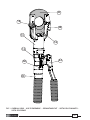
FIG. 1 OVERALL VIEW - VUE D'ENSEMBLE - GESAMTANSICHT - VISTA DEL CONJUNTO -
VISTA D'ASSIEME
18
28
23
03
44
58
19
12
13

29
01
02
58
12
03
14
18
13
44
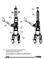
FIG. 2 TOOL POSITION FOR MAINTENANCE OPERATIONS
POSITION DE L'OUTIL POUR L'ENTRETIEN
WERKZEUG WARTUNGSPOSITION
COLOCACION PARA LAS OPERACIONES DE MANTENIMIENTO
POSIZIONAMENTO PER LE OPERAZIONI DI MANUTENZIONE

30
FIG. 3
BLADES REPLACEMENT - CHANGEMENT LAMES - SCHNEIDMESSERWECHSEL - CAMBIO DE LAS CUCHILLAS - CAMBIO DELLE LAME
28
21
19
20
23
29
24
22
25
18
13
14
26
28
18

31
01
02
03
04
05
06
07
08
09
11
10
12
13
14
15
16
17
19
18
23
20
22
21
65
64
62
63
68
66
67
27
26
24
25
28
35
34
30
31
39
38
36
37
33
32
44
43
41
42
51
52
54
53
55
56
58
57
59
61
60
45
40
49
50
46
29
47
48
FIG. 4
LONGITUDINAL SECTION - COUPE LONGITUDINALE - SCHNITTZEICHNUNG - SECCION LONGI-
TUDINAL - SEZIONE LONGITUDINALE
Serial number
Numéro de série
Seriennummer
Número de serie
Numero di matricola

32
This manual is the property of Cembre: any reproduction is forbidden without written permission.
Ce manuel est la proprieté de Cembre: toute reproduction est interdite sauf autorisation écrite.
Diese Bedienungsanleitung ist Eigentum der Firma Cembre.
Ohne vorherige schriftliche Genehmigung darf die Bedienungsanleitung weder vollständig noch teilweise vervielfältigt werden.
Este manual es propiedad de Cembre. Toda reproducción está prohibida sin autorización escrita.
Questo manuale è di proprietà della Cembre: ogni riproduzione é vietata se non autorizzata per scritto.
Cembre Ltd.
Dunton Park
Kingsbury Road, Curdworth - Sutton Coldfield
West Midlands B76 9EB (UK)
Tel.: 01675 470440 - Fax: 01675 470220
E-mail: [email protected]
www.cembre.co.uk
Cembre S.p.A.
Via Serenissima, 9
25135 Brescia (Italia)
Telefono: 030 36921
Telefax: 030 3365766
E-mail: [email protected]
www.cembre.com
Cembre S.a.r.l.
22 Avenue Ferdinand de Lesseps
91420 Morangis (France)
Tél.: 01 60 49 11 90 - Fax: 01 60 49 29 10
CS 92014 - 91423 Morangis Cédex
E-mail: [email protected]
www.cembre.fr
Cembre España S.L.U.
Calle Verano 6 y 8
28850 Torrejón de Ardoz
Madrid (España)
Teléfono: 91 4852580 - Fax: 91 4852581
E-mail: [email protected]
www.cembre.es
Cembre GmbH
Heidemannstraße 166
80939 München (Deutschland)
Telefon: 089 3580676
Telefax: 089 35806777
E-mail: [email protected]
www.cembre.de
Cembre Inc.
Raritan Center Business Park
181 Fieldcrest Avenue
Edison, New Jersey 08837 (USA)
Tel.: (732) 225-7415 - Fax: (732) 225-7414
E-mail: [email protected]
www.cembreinc.com
www.cembre.com
IKUMA GmbH & Co. KG
Boschstraße 7
71384 Weinstadt (Deutschland)
Telefon: 07151 20536-60
Telefax: 07151 20536-80
E-mail: [email protected]
www.ikuma.de
cod. 6261017
-
 1
1
-
 2
2
-
 3
3
-
 4
4
-
 5
5
-
 6
6
-
 7
7
-
 8
8
-
 9
9
-
 10
10
-
 11
11
-
 12
12
-
 13
13
-
 14
14
-
 15
15
-
 16
16
-
 17
17
-
 18
18
-
 19
19
-
 20
20
-
 21
21
-
 22
22
-
 23
23
-
 24
24
-
 25
25
-
 26
26
-
 27
27
-
 28
28
-
 29
29
-
 30
30
-
 31
31
-
 32
32


en otros idiomas
- français: Cembre HT-TC051 Manuel utilisateur
- italiano: Cembre HT-TC051 Manuale utente
- Deutsch: Cembre HT-TC051 Benutzerhandbuch
- português: Cembre HT-TC051 Manual do usuário
Artículos relacionados
-
Cembre HT-TC026 Manual de usuario
-
-
-
-
-
-
-
-
-