
1) TURN OFF POWER.
IMPORTANT: Before you start, NEVER attempt any work without
shutting off the electricity until the work is done.
a) Go to the main fuse, or circuit breaker, box in your home. Place the
main power switch in the “OFF” position.
b) Unscrew the fuse(s), or switch “OFF” the circuit breaker switch(s), that
control the power to the fixture or room that you are working on.
c) Place the wall switch in the “OFF” position. If the fixture to be replaced
has a switch or pull chain, place those in the “OFF” position.
2) Attach mounting strap to outlet box. (Screws not provided)
3) Assemble mounting screws into threaded holes in mounting strap.
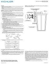
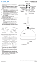
4) Grounding instructions: (See Illus. A or B).
A) On fixtures where mounting strap is provided with a hole and two
raised dimples. Wrap ground wire from outlet box around green
ground screw, and thread into hole.
B) On fixtures where a cupped washer is provided. Attach ground wire
from outlet box under cupped washer and green ground screw, and
thread into mounting strap.
If fixture is provided with ground wire. Connect fixture ground wire to outlet
box ground wire with wire connector. (Not provided.) After following the
above steps.
Never connect ground wire to black or white power supply wires.
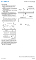
5) Make wire connections (connectors not provided.) Reference chart below
for correct connections and wire accordingly.
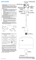
6) Push fixture to ceiling so mounting screws can pass through keyhole slots.
Turn fixture until screwheads appear as in detail. Tighten screws.
7) Insert recommended lamp.
8) Slip glass over fixture so dimples inside fixture slip into gap between
grooves in glass.
9) Turn glass clockwise (approximately 1/4 turn) to secure in place.
NOTE: It is suggested to periodically check security of glass.
1) COUPER LE COURANT ÉLECTRIQUE.
IMPORTANT: TOUJOURS couper l’électricité avant de commencer le
travail.
a) Localiser le coffret à fusibles ou le disjoncteur du domicile. Mettre
l’interrupteur principal en position d’Arrêt.
b) Dévisser le ou les fusibles (ou mettre le disjoncteur sur Arrêt) qui
contrôlent l’alimentation vers le luminaire ou la pièce dans
laquelle le travail est effectué.
c) Mettre l’interrupteur mural en position d’Arrêt. Si le luminaire à
remplacer est doté d’un interrupteur ou d’une chaîne connectée à
l‘interrupteur, placer ces éléments en position d’Arrêt.
2) Instale la placa de montaje a la caja de salida. (No se proporcionan
tornillos.)
3) Instale los tornillos de montaje en los agujeros roscados de la placa de
montaje.
4) Instrucciones de conexión a tierra solamente para los Estados Unidos.
(Vea la ilustraciøn A o B).
A) En las lámparas que tienen el fleje de montaje con un agujero y dos
hoyuelos realzados. Enrollar el alambre a tierra de la caja tomacorriente
alrededor del tornillo verde y pasarlo por el agujero.
B) En las lámparas con una arandela acopada. Fijar el alambre a tierra
de la caja tomacorriente debajo de la arandela acoada y tornillo
verde, y pasar por el fleje de montaje.
Si la lámpara viene con alambre a tierra. Conectar el alambre a tierra de la
lámpara al alambre a tierra de la caja tomacorriente con un conector de
alambres. (No incluido). Después de seguir los pasos anteriores.
Nunca conectar el alambre a tierra a los alambres eléctricos negro o
blanco.
5) Hacer las conexiones de los alambres (conectores no incluidos.) Ver el
cuadro más abajo para las conexiones correctas y alambrar de acuerdo a
esto.
6) Coloque el artefacto de alumbrado en el cielorraso, de modo que los
tornillos de montaje puedan pasar a través de las ranuras tipo bocallave.
Gire el artefacto hasta que las cabessas de los tornillos aparescan como
en el detalle. Apriete los tornillos.
7) Inserte la lámpara recomendada.
8) Deslice el vidrio sobre el artefacto de modo que las depresiones adentro
del artefacto se deslicen en el espacio que hay entre ranuras, en el vidrio.
9) Gire el vidrio en sentido dextrorso (aproximadamente 1/4 de vuelta) para
asegurar en el lugar.
NOTA: Se sugiere que se verifique periódicamente la seguridad del vidrio.
GREEN GROUND
SCREW
CUPPED
WASHER
A
B
OUTLET BOX
GROUND
FIXTURE
GROUND
DIMPLES
WIRE CONNECTOR
(NOT PROVIDED)
OUTLET BOX
GROUND
GREEN GROUND
SCREW
FIXTURE
GROUND
Connect Black or
Red Supply Wire to:
Connect
White Supply Wire to:
Black White
*Parallel cord (round & smooth) *Parallel cord (square & ridged)
Clear, Brown, Gold or Black
without tracer
Clear, Brown, Gold or Black
with tracer
Insulated wire (other than green)
with copper conductor
Insulated wire (other than green)
with silver conductor
*Note: When parallel wires (SPT I & SPT II)
are used. The neutral wire is square shaped
or ridged and the other wire will be round in
shape or smooth (see illus.)
Neutral Wire
ARANDELA
CONCAVA
A
B
TIERRA DE LA
CAJA DE SALIDA
TORNILLO DE TIERRA,
VERDE
DEPRESIONES
TIERRA
ARTEFACTO
CONECTOR DE ALAMBRE
(NO SE PROVEE)
TIERRA DE LA
CAJA DE SALIDA
TORNILLO DE TIERRA,
VERDE
TIERRA
ARTEFACTO
Conectar el alambre de
suministro negro o rojo al
Conectar el alambre de
suministro blanco al
Negro Blanco
*Cordon paralelo (redondo y liso)
*Cordon paralelo (cuadrado y estriado)
Claro, marrón, amarillio o negro
sin hebra identificadora
Claro, marrón, amarillio o negro
con hebra identificadora
Alambre aislado (diferente del verde)
con conductor de cobre
Alambre aislado (diferente del
verde) con conductor de plata
*Nota: Cuando se utiliza alambre paralelo
(SPT I y SPT II). El alambre neutro es de forma
cuadrada o estriada y el otro alambre será de
forma redonda o lisa. (Vea la ilustracíón).
Hilo Neutral
MOUNTING STRAP
PLACA DE MONTAJE
FIXTURE
ARTEFACTO
Date Issued: 8/6/10 IS-8881FL-US
OUTLET BOX
CAJA DE CONEXIONES
GLASS
VIDRIO
SCREW / KEYHOLE
DETAIL
DETALLE DE TORNILLO /
TETALLE DE BOCALLAVE
GAP
ESPACIO
DIMPLE
DEPRESION
GROOVE
RANURA
La página se está cargando...
Transcripción de documentos
OUTLET BOX CAJA DE CONEXIONES MOUNTING STRAP PLACA DE MONTAJE FIXTURE ARTEFACTO DIMPLE DEPRESION SCREW / KEYHOLE DETAIL DETALLE DE TORNILLO / TETALLE DE BOCALLAVE GROOVE RANURA GAP ESPACIO GLASS VIDRIO 1) Turn off power. IMPORTANT: Before you start, NEVER attempt any work without shutting off the electricity until the work is done. a) Go to the main fuse, or circuit breaker, box in your home. Place the main power switch in the “OFF” position. b) Unscrew the fuse(s), or switch “OFF” the circuit breaker switch(s), that control the power to the fixture or room that you are working on. c) Place the wall switch in the “OFF” position. If the fixture to be replaced has a switch or pull chain, place those in the “OFF” position. 2) Attach mounting strap to outlet box. (Screws not provided) 3) Assemble mounting screws into threaded holes in mounting strap. 4) Grounding instructions: (See Illus. A or B). A) On fixtures where mounting strap is provided with a hole and two raised dimples. Wrap ground wire from outlet box around green ground screw, and thread into hole. B) On fixtures where a cupped washer is provided. Attach ground wire from outlet box under cupped washer and green ground screw, and thread into mounting strap. If fixture is provided with ground wire. Connect fixture ground wire to outlet box ground wire with wire connector. (Not provided.) After following the above steps. Never connect ground wire to black or white power supply wires. A 1) Couper le courant électrique. IMPORTANT: TOUJOURS couper l’électricité avant de commencer le travail. a) Localiser le coffret à fusibles ou le disjoncteur du domicile. Mettre l’interrupteur principal en position d’Arrêt. b) Dévisser le ou les fusibles (ou mettre le disjoncteur sur Arrêt) qui contrôlent l’alimentation vers le luminaire ou la pièce dans laquelle le travail est effectué. c) Mettre l’interrupteur mural en position d’Arrêt. Si le luminaire à remplacer est doté d’un interrupteur ou d’une chaîne connectée à l‘interrupteur, placer ces éléments en position d’Arrêt. 2) Instale la placa de montaje a la caja de salida. (No se proporcionan tornillos.) 3) Instale los tornillos de montaje en los agujeros roscados de la placa de montaje. 4) Instrucciones de conexión a tierra solamente para los Estados Unidos. (Vea la ilustraciøn A o B). A) En las lámparas que tienen el fleje de montaje con un agujero y dos hoyuelos realzados. Enrollar el alambre a tierra de la caja tomacorriente alrededor del tornillo verde y pasarlo por el agujero. B) En las lámparas con una arandela acopada. Fijar el alambre a tierra de la caja tomacorriente debajo de la arandela acoada y tornillo verde, y pasar por el fleje de montaje. Si la lámpara viene con alambre a tierra. Conectar el alambre a tierra de la lámpara al alambre a tierra de la caja tomacorriente con un conector de alambres. (No incluido). Después de seguir los pasos anteriores. Nunca conectar el alambre a tierra a los alambres eléctricos negro o blanco. A B ConeCTor De AlAMBre (no Se proVee) TIerrA De lA CAJA De SAlIDA B wIre ConneCTor (noT proVIDeD) ouTleT BoX GrounD fIXTure GrounD DIMpleS Green GrounD SCrew ouTleT BoX GrounD Green GrounD SCrew CuppeD wASHer 5) Make wire connections (connectors not provided.) Reference chart below for correct connections and wire accordingly. Connect Black or Red Supply Wire to: Connect White Supply Wire to: Black White *Parallel cord (round & smooth) *Parallel cord (square & ridged) Clear, Brown, Gold or Black without tracer Clear, Brown, Gold or Black with tracer Insulated wire (other than green) with copper conductor Insulated wire (other than green) with silver conductor *Note: When parallel wires (SPT I & SPT II) are used. The neutral wire is square shaped or ridged and the other wire will be round in shape or smooth (see illus.) Neutral Wire 6) Push fixture to ceiling so mounting screws can pass through keyhole slots. Turn fixture until screwheads appear as in detail. Tighten screws. 7) Insert recommended lamp. 8) Slip glass over fixture so dimples inside fixture slip into gap between grooves in glass. 9) Turn glass clockwise (approximately 1/4 turn) to secure in place. NOTE: It is suggested to periodically check security of glass. Date Issued: 8/6/10 DepreSIoneS TornIllo De TIerrA, VerDe fIXTure GrounD TIerrA ArTefACTo TIerrA ArTefACTo TIerrA De lA CAJA De SAlIDA TornIllo De TIerrA, VerDe ArAnDelA ConCAVA 5) Hacer las conexiones de los alambres (conectores no incluidos.) Ver el cuadro más abajo para las conexiones correctas y alambrar de acuerdo a esto. Conectar el alambre de suministro negro o rojo al Conectar el alambre de suministro blanco al Negro Blanco *Cordon paralelo (redondo y liso) *Cordon paralelo (cuadrado y estriado) Claro, marrón, amarillio o negro sin hebra identificadora Claro, marrón, amarillio o negro con hebra identificadora Alambre aislado (diferente del verde) con conductor de cobre Alambre aislado (diferente del verde) con conductor de plata *Nota: Cuando se utiliza alambre paralelo (SPT I y SPT II). El alambre neutro es de forma cuadrada o estriada y el otro alambre será de forma redonda o lisa. (Vea la ilustracíón). Hilo Neutral 6) Coloque el artefacto de alumbrado en el cielorraso, de modo que los tornillos de montaje puedan pasar a través de las ranuras tipo bocallave. Gire el artefacto hasta que las cabessas de los tornillos aparescan como en el detalle. Apriete los tornillos. 7) Inserte la lámpara recomendada. 8) Deslice el vidrio sobre el artefacto de modo que las depresiones adentro del artefacto se deslicen en el espacio que hay entre ranuras, en el vidrio. 9) Gire el vidrio en sentido dextrorso (aproximadamente 1/4 de vuelta) para asegurar en el lugar. NOTA: Se sugiere que se verifique periódicamente la seguridad del vidrio. IS-8881FL-US-
 1
1
-
 2
2


Kichler Lighting 8881NI Manual de usuario
- Tipo
- Manual de usuario
- Este manual también es adecuado para
en otros idiomas
- français: Kichler Lighting 8881NI Manuel utilisateur
- English: Kichler Lighting 8881NI User manual
Artículos relacionados
-
Kichler Lighting 206NI Manual de usuario
-
 Kichler Lighting 42380NILEDR Manual de usuario
-
 Kichler Lighting 43354CH Manual de usuario
-
 Kichler Lighting 49623BKTLED Manual de usuario
-
 Kichler Lighting 7772NI Manual de usuario
-
 Kichler Lighting 44003NI Manual de usuario
-
 Kichler Lighting 43359CH Manual de usuario
-
Kichler Lighting 43194MIZ Manual de usuario


