Sanyo VA-82LAN Guía de instalación
- Categoría
- Cámaras de seguridad
- Tipo
- Guía de instalación

This option board provides simultaneous delivery of video in the JPEG and H.264 formats and also bi-directional video and
voice communications between the camera and PC.
■ Applicable models: Power Board Unit VA-84SA or VA-80SA
■ Cautions on Connecting Microphone/Speakers for Bi-directional Voice Communication
● Howling may occur if microphone and speakers are put too close. Move them apart or change the speakers orientation to
prevent howling. Also adjust the microphone sensitivity as well as the speaker volume.
● For speakers on the camera side, use speakers with built-in amplifier.
■ System Requirements
The system requirements for camera operation via network are as follows:
•PC: IBM PC/AT and compatibles
•OS: Windows XP Home Edition/Windows XP Professional
•CPU: Pentium IV (2.0GHz or higher) (3.0 GHz or higher for using the VA-SW3050Lite)
• Memory: 512MB or more (1 GB or more for using the VA-SW3050)
• Network interface: 10Base-T/100Base-TX (RJ-45 connector)
• Graphics processor: nVIDIA: GeForce 6000 series or higher
ATI: RADEON X1000 series or higher
• Display card: 1024 x 768 pixels or higher, 16 million colors or higher
• Web browser: Internet Explorer Ver.6.0 or higher
•Voice: Sound card and speakers with 100% DirectX compatibility
INSTALLATION MANUAL
Option Board (Network)
About this manual
Please read this installation manual before installing this unit, and always follow the instructions in it for proper use.
VA-82LAN
English Deutsch Français Español
中文简体
L9EBH_WA(VA-82LAN_INSTALLATION).book 1 ページ 2007年7月30日 月曜日 午後5時31分

2
Connection - 1
Connect the camera to the LAN through a switching hub using LAN cables (straight type).
✱4
✱5
✱1
✱2
✱3
Switching hub
PC
Speaker
Microphone
LAN cable (straight type)
Max. 100 m
LAN cable (straight type)
Voice signal transmission to camera
Voice signal check at PC
Video output
(BNC connector)
Voice output (black)
3.5 φ mini jack
(supplied with the
option board)
External microphone
input (white)
3.5 φ mini jack
(supplied with the option
board)
Microphone
Speaker
TV monitor
Video/voice data
Max. 100 m
When directly connecting
the camera to a PC, use the
LAN cable (cross type).
To prevent electromagnetic interference:
✱
1: Attach the white square clamping core (large) by winding the cable around
it twice.
✱
2, 3: Attach the two black round clamping cores (small) by nipping the cables
with them.
(Both cores need to be attached to the cables inside the camera body.)
✱
4: Attach the white round clamping core (large) by winding the cable around
it twice.
✱
5: Attach the white round clamping core (small) by nipping the cable with it.
* Use shielded LAN cables.
When using the IE/VA-SW3050Lite/VA-SW3050
server version:
You need the VA-SW3050 client version to
view live/replayed video, because the
VA-SW3050 server version is used for
recording purpose only.
When using the IE/VA-SW3050Lite/
VA-SW3050 client version:
You need a PC for the VA-SW3050
server version.
L9EBH_WA(VA-82LAN_INSTALLATION).book 2 ページ 2007年7月30日 月曜日 午後5時31分

3
Connection - 1
■ Internet connection
Connect the camera to a router or ADSL modem with LAN interface
using LAN cables.
■ About the internet connection
Port forwarding must be set on two of the router ports (camera side).
For details on how to set port forwarding, please refer to your router's
instruction manual.
• Video port number
Conduct the following port forwarding settings with respect to the
router:
IP address on the LAN side: Camera IP address (default:
192.168.0.2)
Port number on the LAN side: Camera video port number
(default: 80)
Port number on the WAN side: Optional
For communication, use TCP/IP.
• Voice port number
Conduct the following port forwarding settings with respect to the
router:
IP address on the LAN side: Camera IP address (default:
192.168.0.2)
Port number on the LAN side: Camera voice port number
(default: 34341)
Port number on the WAN side: Camera voice port number
(default: 34341)
For communication, use UDP.
When installing multiple cameras on the LAN side, change the voice port
number for the second camera onwards accordingly (default: 34341),
and make the port forwarding setting for the corresponding router.
When connecting to a router, use the straight type LAN cable.
When connecting to an ADSL modem or other devices, refer to the
instruction manual for the device.
✱1
✱2
Router or
ADSL modem
Internet
To prevent
electromagnetic
interference:
✱
1:
Attach the white
round clamping core
(large) by winding
the cable around it
twice.
✱
2:
Attach the white
round clamping core
(small) by nipping
the cable with it.
MEMO: When viewing video in H.264 format over the Internet, set the
communication protocol of H.264 to "HTTP". (See page 27 of
the INSTRUCTION MANUAL [VA-82LAN] contained in the
supplied CD-ROM.)
L9EBH_WA(VA-82LAN_INSTALLATION).book 3 ページ 2007年7月30日 月曜日 午後5時31分

4
1. Installing the Option Board
1
Use the three supplied screws to install the
option board on the power board unit (VA-84SA
or VA-80SA)(see the figure on the left).
2
Pass the LAN cable through the cable hole and
plug it into the LAN port.
Note:
When it is difficult to plug in or pull out the LAN cable, we
recommend that you either use a LAN cable that has no plug cover
at the cable end, or displace the cover if there is one.
3
When using the voice interface, connect the two
supplied cables to the option board.
Connect the red connector cable to the CN805 (red) terminal for
voice output and the white connector cable to the CN806 (white)
terminal for microphone input. These connector cables should be
fixed firmly by wrapping once around the fixer.
4
Configure the network settings (see page 5).
CN806
CN805
1
1
1
2
3
3
A
Note: Arrange the two cables so as not to contact the board A.
L9EBH_WA(VA-82LAN_INSTALLATION).book 4 ページ 2007年7月30日 月曜日 午後5時31分

5
2. Configuring the Network Settings
On the NETWORK SETTING screen, specify the options required for connecting the camera to the network (LAN).
• The NETWORK SETTING screen appears only when the camera is equipped with this option board.
• For displaying the menu screen, refer to the instruction manual supplied with the camera.
• In the following instructions, the lever operations of the system controller (VSP-9000) are shown using xy for vertical operation and vw for horizontal
operation.
1
Use the lever (xy) to select “IP ADDRESS”, use
the lever (vw) to select the IP address assignment
option, and press the [ENTER] button.
2
Use the lever (xy) to select the setting item you
want to change, and press the lever to the right
(vw).
ROnly the selected option is displayed on the screen, and “x”
appears below the address.
CAMERA
LENS
PAN/TILT
AUTO MODE
PASSWORD
LANGUAGE
OPTION
ADVANCED MENU
SET
SET
SET
SET
SET
SET
SET
SET
y
y
y
y
y
y
y
y
ENTER
y
y
OPTION
INFORMATION
AUTO FLIP
NETWORK
SET
OFF
SET
ENTER
NETWORK SETTING
IP ADDRESS
PORT
ALARM
MAC ADDRESS
08-00-7I-81-25-J2
FIX
00080
OUT1/2
y
Menu screen
Use the lever (xy) to select “OPTION”.
OPTION screen NETWORK SETTING screen
Use the lever (xy) to select “NETWORK”. Perform the network settings.
FIX : Manual assignment (default: 192.168.0.2)
Go to step
2 (IP ADDRESS SETTING).
AUTO
Automatic assignment (DHCP)
Confirm the information in the screen, and go to step
4.
MEMO: The “MAC ADDRESS” cannot be changed.
NETWORK SETTING
IP ADDRESS
PORT
ALARM
MAC ADDRESS
08-00-7I-81-25-J2
FIX
00080
OUT1/2
y
ENTER
R
IP ADDRESS SETTING
IP ADDRESS
192.168.000.002
SUBNETMASK
255.255.255.000
GATEWAY
192.168.000.001
IP ADDRESS SETTING
IP ADDRESS
192.168.000.002
x
L9EBH_WA(VA-82LAN_INSTALLATION).book 5 ページ 2007年7月30日 月曜日 午後5時31分

6
2. Configuring the Network Settings
3
Select the digit to be changed, and specify the
value.
• Use the lever (vw) to move “x” to the digit you want to change,
and use the lever (vw) to select the number.
• If you change the setting item, use the lever vw) to move “x” to
either end, and press the lever (vw) toward the same end. This
displays the IP ADDRESS SETTING screen, returning you to
step
2.
4
Use the lever (xy) to select “MENU” – “BACK”,
and press the [ENTER] button.
RReturns to the NETWORK SETTING screen.
5
To change the port number, use the lever (xy) to
select “PORT”, and press the lever to the right (w).
RUse the same procedure as step 3 to change the port number
to your desired value (between 1 and 65535).
6
Use the lever (xy) to select “ALARM” and then
use the lever (vw) to select the alarm output
option.
•OFF: Disables alarm output from the camera to the
network.
•OUT1: Enables alarm output 1 to be sent to the network.
•OUT2: Enables alarm output 2 to be sent to the network.
• OUT1/2: Enables alarm outputs 1 and 2 to be sent to the
network (default setting).
7
Use the lever (xy) to select “MENU”, use the
lever (vw) to select “END”, and press [ENTER].
RCloses the settings screen and returns to the normal monitoring
screen.
• To return to the previous screen, select “BACK” and press the
[ENTER] button.
IP ADDRESS SETTING
IP ADDRESS
192.168.000.052
x
NETWORK SETTING
IP ADDRESS
PORT
ALARM
MAC ADDRESS
08-00-7I-81-25-J2
FIX
00080
x
OUT1/2
y
NETWORK SETTING
IP ADDRESS
PORT
ALARM
MAC ADDRESS
08-00-7I-81-25-J2
FIX
00090
OUT1/2
y
L9EBH_WA(VA-82LAN_INSTALLATION).book 6 ページ 2007年7月30日 月曜日 午後5時31分

7
2. Configuring the Network Settings
■ Screen Sequence
IP ADDRESS SETTING
IP ADDRESS
192.168.000.002
SUBNETMASK
255.255.255.000
GATEWAY
192.168.000.001
MENU BACK
NETWORK SETTING
IP ADDRESS
PORT
ALARM
MAC ADDRESS
08-00-7I-81-25-J2
MENU
FIX
00080
OUT1/2
BACK
y
CAMERA
LENS
PAN/TILT
AUTO MODE
PASSWORD
LANGUAGE
OPTION
ADVANCED MENU
PRESET
MENU
SET
SET
SET
SET
SET
SET
SET
SET
OFF
END
y
y
y
y
y
y
y
y
y
y
OPTION
INFORMATION
AUTO FLIP
NETWORK
PRESET
MENU
SET
OFF
SET
OFF
BACK
AUTO
FIX
OFF
OUT1
OUT2
OUT1/2
1-65535
L9EBH_WA(VA-82LAN_INSTALLATION).book 7 ページ 2007年7月30日 月曜日 午後5時31分

8
3. Flow of Camera Operation through to Network Operation
Perform the following procedures according to the detailed instructions given in the INSTRUCTION MANUAL [VA-82LAN] contained in the supplied
CD-ROM.
Refer to
1 Installing the “H.264 Plug-in” from the supplied CD-ROM onto PC
3
5
2 Accessing the Camera
Enter your user name and password, and then select a language you want to display on the screen.
User name: admin
Password: admin
7
5
3 Monitoring The Live Video In The Main Screen
9
5
4 Selecting the Operating Conditions
Using the [MAIN SETTINGS] screen for an administrative user, configure the detailed settings for administration.
When you access the camera for the first time, be sure to perform the settings on the [CLOCK SETTINGS] screen.
15
5
5 Changing the Camera Settings
Changes in the camera settings can be made through the network connection.
41
MEMO: • After you turn on the power, wait approximately one minute before network connection is established.
• When the TCP/IP settings on your PC are required, refer to page 5 of the INSTRUCTION MANUAL [VA-82LAN] contained in the
supplied CD-ROM.
L9EBH_WA(VA-82LAN_INSTALLATION).book 8 ページ 2007年7月30日 月曜日 午後5時31分

9
4. Software Setup Procedure for VA-SW3050Lite
The VA-SW3050Lite software achieves multiple monitoring by using up to 128 cameras and allows you to switch the monitoring screen
between single, 4-part split and 16-part split viewing.
Perform the following procedures according to the detailed instructions given in the INSTRUCTION MANUAL [VA-SW3050Lite] contained in the
supplied CD-ROM.
1 Installing the VA-SW3050Lite Software (see next page)
5
Refer to
2 Starting and Logging in to the VA-SW3050Lite Software
Double-click the “Network Recorder” shortcut icon created on the desktop.
USER ID: admin
PASSWORD: admin
5
5
3 Registering the Cameras with the Software
Register the camera(s) to access, and configure the camera settings such as IP address and camera title.
7
5
4 Viewing the Live Video
11
MEMO: • After you turn on the power, wait approximately one minute before you can login.
• To view the INSTRUCTION MANUAL contained in the supplied CD-ROM, you need Adobe
®
Reader
®
application. If your PC has not
been installed with it, you can download it for installation from the following web site at Adobe Systems Incorporated.
http://www.adobe.com
L9EBH_WA(VA-82LAN_INSTALLATION).book 9 ページ 2007年7月30日 月曜日 午後5時31分

10
4. Installing the VA-SW3050Lite Software
Start the installation program from the software CD, and use the interactive dialog boxes to advance the installation process.
1
Double-click “Setup.exe” contained in the supplied
CD-ROM.
2
The “Welcome to the InstallShield Wizard for
VA-SW3050” dialog appears.
Click [Next].
3
The “License Agreement” dialog appears.
Select the “I accept the agreement” option and then click [Next].
4
The “Select Destination Location” dialog appears.
Click [Next].
• To change the destination folder in which you want to save the
VA-SW3050Lite software, click [Browse] and select the desired
folder. You may also type the folder name directly in the box.
5
The “Select Start Menu Folder” dialog appears.
Click [Next].
• To change the start menu folder, click [Browse] and select the
desired folder. You may also type the folder name directly in the
box.
6
The “Ready to Install” dialog appears.
Click [Install].
☞ Installing
7
The “Completing the VA-SW3050 Setup Wizard” dialog
appears.
Click [Finish].
☞ Now you have installed the VA-SW3050Lite software
successfully.
You will find the “Network Recorder” short cut icon on the
desktop.
MEMO:
• Microsoft .NET Framework 1.1 is required to use the
VA-SW3050Lite software. If your PC has not been installed
with it, an automatic installation program will show you a
confirmation dialog box to start its setup process, when
you double-click “Setup”. It will be about two minutes
before the installation program finishes.
• Once the installation is finished, you may be prompted to
restart the PC. Follow the instructions that may appear on
the screen.
L9EBH_WA(VA-82LAN_INSTALLATION).book 10 ページ 2007年7月30日 月曜日 午後5時31分

11
Specifications
Appearance and specifications are subject to change without prior notice
or obligations.
■ License for Software Contained in CD-ROM
• Please read carefully the terms and conditions contained in the
license agreement that appears on the screen during the software
installation process. Provided that you have agreed to all the terms
and conditions therein, you may use the software subject to the
license agreement.
• For information on the other products or services provided by third
parties which are introduced in the CD-ROM, please contact each
supplier or manufacturer.
■ Copyright notice
This instruction manual is copyrighted by SANYO Electric Co., Ltd.
No materials contained in this manual may be reproduced in any format
without the prior permission of the copyright holder.
Microsoft, Windows and Internet Explorer are registered trademarks or
trademarks of Microsoft Corporation in the United States and other
countries.
The official name for “Windows” used in this manual is Microsoft
®
Windows
®
Operating System. In this manual, note that the word
“Windows” refers to both “Microsoft
®
Windows
®
2000 Operating System”
and “Microsoft
®
Windows
®
XP Operating System”.
Intel and Pentium are registered trademarks or trademarks of Intel
Corporation and its subsidiaries in the United States and other countries.
IBM and IBM PC/AT are trademarks of International Business Machines
Corporation.
Adobe Reader is a trademark of Adobe Systems Incorporated.
UPnP is a trademark of UPnP Implementers Corporation, which is
established by the UPnP Forum SC.
Java is a trademark of Sun Microsystems, Inc.
All other brands and product names in this manual are the registered
trademarks or trademarks of their respective owners.
Power
consumption
21 W (for AC 24 V), 22 W (for AC 230 V)
When installed on the main unit
Power source Supplied from main unit
Weight Approx. 33 g (1.2 oz)
Accessory
Screw................................................................... 3
Cable with 3.5 φ mini jack
(black and white)......................................... each 1
Clamping core...................................................... 5
CD-ROM (VA-SW3050Lite).................................. 1
L9EBH_WA(VA-82LAN_INSTALLATION).book 11 ページ 2007年7月30日 月曜日 午後5時31分

L9EBH_WA(VA-82LAN_INSTALLATION).book 12 ページ 2007年7月30日 月曜日 午後5時31分

English Deutsch Français Español
中文简体
日本語
Diese Optionskarte ermöglicht gleichzeitig die Bildwiedergabe in den Formaten JPEG und H.264 und zudem die bidirektionale
Bild- und Sprachkommunikation zwischen Kamera und PC.
■ Modelle: Stromversorgungsmodul VA-84SA oder VA-80SA
■ Vorsichtsmaßnahmen für den Anschluss von Mikrofon/Lautsprechern für die bidirektionale
Sprachkommunikation
● Wenn der Abstand zwischen Mikrofon und Lautsprecher zu klein ist, können Misstöne (Heulen) entstehen. Vergrößern Sie
den Abstand oder verändern Sie die Ausrichtung der Lautsprecher, um Heulgeräuschen vorzubeugen. Darüber hinaus
empfiehlt es sich, die Empfindlichkeit des Mikrofons und die Lautstärke der Lautsprecher zu regulieren.
● Verwenden Sie Geräte mit eingebautem Verstärker für die Lautsprecher auf der Kameraseite.
■ Systemanforderungen
Die Systemvoraussetzungen für den Kamerabetrieb über das Netzwerk sind wie folgt:
•PC: IBM PC/AT und kompatible Modelle
• Betriebssystem: /Windows XP Home Edition/Windows XP Professional
•CPU: Pentium IV (2,0 GHz oder höher) (Mindestens 3,0 GHz bei Verwendung des VA-SW3050Lite)
• Arbeitsspeicher: mindestens 512 MB (Mindestens 1 GB bei Verwendung des VA-SW3050)
• Netzwerk-Schnittstelle: 10Base-T/100Base-TX (RJ45-Steckverbinder)
•Grafikchip: nVIDIA: GeForce 6000 oder höher
ATI: RADEON X1000 oder höher
• Grafikkarte: Mindestens 1024 x 768 Bildpunkte, Mindestens 16 Millionen Farben
• Internet-Browser: Internet Explorer Version 6.0 oder höher
• Sprachausgabe: Soundkarte und Lautsprecher mit 100% DirectX-Kompatibilität
INSTALLATIONSANLEITUNG
Optionskarte (Netzwerk)
Zu dieser Anleitung
Lesen Sie bitte diese Anleitung vor der Installation dieser Einheit sorgfältig durch
und befolgen Sie die Anweisungen für den richtigen Gebrauch.
VA-82LAN
L9EBH_WA(VA-82LAN_INSTALLATION).book 1 ページ 2007年7月30日 月曜日 午後5時31分

2
Anschlussschema - 1
Schließen Sie die Kamera über ein Umschalt-Hub mit LAN-Kabeln (Patchkabeln) an das LAN-Netzwerk an.
✱4
✱5
✱1
✱2
✱3
Umschalt-Hub
PC
Lautsprecher
Mikrofon
LAN-Netzwerkkabel (Patchkabel)
Max. 100 m
LAN-Netzwerkkabel (Patchkabel)
Sprachsignalübertragung an Kamera
Sprachsignalüberprüfung am PC
Video-Ausgang
(BNC-Stecker)
Sprach-Ausgang (schwarz)
3,5 φ Miniklinkenbuchse
(mit der Optionskarte
geliefert)
Externer Mikrofon-
Eingang (weiß)
3,5 φ Miniklinkenbuchse
(mit der Optionskarte
geliefert)
Mikrofon
Lautsprecher
TV-Monitor
Video-/
Sprachdaten
Max. 100 m
* Geschirmte LAN-Netzwerkkabel verwenden.
Zum direkten Anschluss der
Kamera an einen PC verwenden
Sie das LAN-Kabel
(Crossover-Kabel).
Vermeiden von elektromagnetischen Störungen:
✱
1: Bringen Sie den weißen quadratischen Ferritkern (groß) an, indem Sie
das Kabel zweimal darum wickeln.
✱
2, 3: Bringen Sie die zwei schwarzen runden Ferritkerne (klein) an, indem
Sie das Kabel mit diesen einklemmen. (Beide Ferritkerne müssen im
Kameragehäuse an das Kabel angebracht werden.)
✱
4: Bringen Sie den weißen runden Ferritkern (groß) an, indem Sie das Kabel
zweimal darum wickeln.
✱
5: Bringen Sie den weißen runden Ferritkern (klein) an, indem Sie das Kabel
mit diesem einklemmen.
Bei Verwendung der Version IE/VA-SW3050Lite/
VA-SW3050 Server:
Für das Betrachten von Live-Videobildern bzw. die
Videowiedergabe benötigen Sie die Version
VA-SW3050 Client, da die Version VA-SW3050
Server nur zu Aufnahmezwecken verwendet wird.
Bei Verwendung der Version IE/
VA-SW3050Lite/VA-SW3050 Client:
Für die Version VA-SW3050 Server
benötigen Sie einen PC.
L9EBH_WA(VA-82LAN_INSTALLATION).book 2 ページ 2007年7月30日 月曜日 午後5時31分

3
Anschlussschema - 2
■ Internet-Anschluss
Verbinden Sie die Kamera mithilfe von LAN-Kabeln mit einem Router
oder ADSL-Modem mit LAN-Schnittstelle.
■ Informationen zur Internet-Verbindung
Die Port-Weiterleitung muss auf zwei Ports des Routers (Kamera-Seite)
eingestellt werden.
Für Einzelheiten über die Vorgehensweise zur Einstellung der
Port-Weiterleitung, schlagen Sie bitte in der Bedienungsanleitung des
Routers nach.
• Video-Port-Nummer
Führen Sie die folgenden Einstellungen für die Port-Weiterleitung unter
Berücksichtigung des Routers aus:
IP-Adresse auf der LAN-Seite:
Kamera-IP-Adresse (Grundeinstellung: 192.168.0.2)
Port-Nummer auf der LAN-Seite:
Kamera-Video-Port-Nummer (Grundeinstellung: 80)
Port-Nummer auf der WAN-Seite: Optional
Verwenden Sie für die Kommunikation das TCP/IP-Protokoll.
• Voice-Port-Nummer
Führen Sie die folgenden Einstellungen für die Port-Weiterleitung unter
Berücksichtigung des Routers aus:
IP-Adresse auf der LAN-Seite:
Kamera-IP-Adresse (Grundeinstellung: 192.168.0.2)
Port-Nummer auf der LAN-Seite:
Kamera-Voice-Port-Nummer (Grundeinstellung: 34341)
Port-Nummer auf der WAN-Seite: Kamera-Voice-Port-Nummer
(Grundeinstellung: 34341)
Verwenden Sie für die Kommunikation das UDP-Protokoll.
Ändern Sie bei Installation mehrerer Kameras auf der LAN-Seite die
Voice-Port-Nummer ab der zweiten Kamera entsprechend (Grundeinstellung:
34341) und nehmen Sie die Einstellung für die Port-Weiterleitung für den
jeweiligen Router vor.
Verwenden Sie Patch-Netzwerkkabel, wenn Sie einen Router
anschließen.
Bei Anschluss an ein ADSL-Modem oder andere Geräte, wird auf
die Bedienungsanleitung des angeschlossenen Geräts verwiesen.
✱1
✱2
Router oder
ADSL-Modem
Internet
Vermeiden von
elektromagnetischen
Störungen:
✱
1:
Bringen Sie den
weißen runden
Ferritkern (groß) an,
indem Sie das
Kabel zweimal
darum wickeln.
✱2: Bringen Sie den
weißen runden
Ferritkern (klein) an,
indem Sie das
Kabel mit diesem
einklemmen.
MEMO: Stellen Sie zum Betrachten von Videobildern im Format H.264
über das Internet das Kommunikationsprotokoll für H.264 auf
„HTTP“ ein. (Siehe Seite 27 der BEDIENUNGSANLEITUNG
[VA-82LAN] auf der mitgelieferten CD-ROM.)
L9EBH_WA(VA-82LAN_INSTALLATION).book 3 ページ 2007年7月30日 月曜日 午後5時31分

4
1. Installieren der Optionskarte
1
Verwenden Sie die drei mitgelieferten Schrauben
zum Installieren der Optionskarte auf dem
Stromversorgungsmodul (VA-84SA oder
VA-80SA) (siehe Abb. links).
2
Führen Sie das LAN-Kabel durch die
Kabeldurchführung und stecken Sie es in den
LAN-Anschluss ein.
Hinweis:
Lässt sich das LAN-Kabel nur schwer einstecken oder abziehen,
empfehlen wir, entweder ein LAN-Kabel ohne Steckerabdeckung
am Kabelende zu verwenden oder die ggf. vorhandene
Abdeckung beiseite zu schieben.
3
Bei Verwendung der Sprachschnittstelle die zwei
mitgelieferten Kabel an die Optionskarte
anschließen.
Das Kabel mit dem roten Stecker an die Klemme CN805 (rot) für
die Sprachausgabe und das Kabel mit dem weißen Stecker an die
Klemme CN806 (weiß) für den Mikrofoneingang anschließen.
Diese Steckerkabel sollten zur sicheren Fixierung einmal um die
Befestigung gewickelt werden
4
Konfigurieren Sie die Netzwerkeinstellungen
(siehe Seite 5).
CN806
CN805
1
1
1
2
3
3
A
Hinweis: Ordnen Sie die zwei Kabel so an, dass diese die Karte A
nicht berühren.
L9EBH_WA(VA-82LAN_INSTALLATION).book 4 ページ 2007年7月30日 月曜日 午後5時31分

5
2. Konfiguration der Netzwerkeinstellungen
Geben Sie im Bildschirm NETZWERK EINST. die für den Anschluss der Kamera an das Netzwerk (LAN) erforderlichen
Optionen ein.
• Der Bildschirm NETZWERK EINST. erscheint nur, wenn die Kamera mit dieser Optionskarte ausgestattet ist.
• Zur Anzeige des Menübildschirms siehe die mit der Kamera mitgelieferte Bedienungsanleitung.
• In den folgenden Anweisungen wird die Joystick-Bedienung am Systemsteuergerät (VSP-9000) mit xy für die vertikale Bedienung und vw für die
horizontale Bedienung dargestellt.
1
Wählen Sie mit Joystick (
xy
) den Eintrag „IP-ADRESSE“,
dann mit Joystick (
vw
) die Option der
IP-Adresszuweisung und drücken Sie die [ENTER]-Taste.
2
Wählen Sie mit Joystick (xy) die Einstellung, die
geändert werden soll, und drücken Sie den
Joystick nach rechts (w).
RNur die gewählte Option wird angezeigt und „x“ wird unter der
Adresse eingeblendet.
KAMERA
OBJEKTIV
PAN/KIPP
AUTO-MODUS
KENNWORT
SPRACHE
OPTION
ERWEIT. MENUE
EINST
EINST
EINST
EINST
EINST
EINST
EINST
EINST
y
y
y
y
y
y
y
y
ENTER
y
y
OPTION
INFORMATION
AUTOM. UMDREH.
NETZWERK
EINST
AUS
EINST
ENTER
NETZWERK EINST.
IP-ADRESSE
PORT
ALARM
MAC-ADRESSE
08-00-7I-81-25-J2
FEST
00080
AL-1/2
y
Menübildschirm
Wählen Sie mit dem Joystick xy
den Eintrag „OPTION“.
Bildschirm OPTION Bildschirm NETZWERK EINST.
Wählen Sie mit dem Joystick xy den
Eintrag „NETZWERK“.
Nehmen Sie die
Netzwerkeinstellungen vor.
FEST : Manuelle Zuweisung (Grundeinstellung: 192.168.0.2).
Weiter mit Schritt
2 (IP-ADRESSE EINST.).
AUTO : Automatische Zuweisung (DHCP). Die angezeigte
Information prüfen und weiter mit Schritt
4.
MEMO: Die „MAC-ADRESSE“ kann nicht geändert werden.
NETZWERK EINST.
IP-ADRESSE
PORT
ALARM
MAC-ADRESSE
08-00-7I-81-25-J2
FEST
00080
AL-1/2
y
ENTER
R
IP-ADRESSE EINST.
IP-ADRESSE
192.168.000.002
SUBNETZMASKE
255.255.255.000
GATEWAY
192.168.000.001
IP-ADRESSE EINST.
IP-ADRESSE
192.168.000.002
x
L9EBH_WA(VA-82LAN_INSTALLATION).book 5 ページ 2007年7月30日 月曜日 午後5時31分

6
2. Konfiguration der Netzwerkeinstellungen
3
Wählen Sie die zu ändernde Ziffer aus und legen
Sie den Wert fest.
• Bewegen Sie mit dem Joystick (vw) das Zeichen „x“ auf die zu
ändernde Ziffer und wählen Sie mit dem Joystick (xy) die
gewünschte Zahl.
• Um zu einer anderen Einstelloption zu wechseln, bewegen Sie
mit dem Joystick (vw) das Zeichen „x“ an ein Ende und
drücken Sie den Joystick (vw) zum selben Ende hin. Hierdurch
wird der Bildschirm IP-ADRESSE EINST. angezeigt und zu
Schritt
2 zurückgekehrt.
4
Wählen Sie mit dem Joystick (xy) „MENUE“ –
„ZURUECK“ und drücken Sie die [ENTER]-Taste.
RDamit wird zum Bildschirm „NETZWERK EINST.“
zurückgeschaltet.
5
Zum Ändern der Port-Nummer wählen Sie mit dem
Joystick (xy) den Eintrag „PORT“ und drücken Sie
den Joystick nach rechts (w).
RVerwenden Sie das in Schritt 3 beschriebene Verfahren, um
die Port-Nummer auf den gewünschten Wert einzustellen
(zwischen 1 und 65535).
6
Wählen Sie mit dem Joystick (xy) den Eintrag
„ALARM“ und dann mit dem Joystick (vw) die
Option für den Alarmausgang.
•AUS: Deaktiviert den Alarmausgang von der Kamera zum
Netzwerk.
•AL-1: Aktiviert den Alarmausgang 1 zur Signalsendung an
das Netzwerk.
•AL-2: Aktiviert den Alarmausgang 2 zur Signalsendung an
das Netzwerk.
• AL-1/2: Aktiviert die Alarmausgänge 1 und 2 zur Signal-
sendung an das Netzwerk (Grundeinstellung).
7
Wählen Sie mit dem Joystick (xy) „MENUE“ und
dann mit dem Joystick (vw) „ENDE“ und drücken
Sie [ENTER].
R Schließt den Einstellbildschirm und schaltet zum normalen
Monitorbildschirm zurück.
• Um in den vorherigen Bildschirm zurückzukehren, wählen Sie
„ZURUECK“ und drücken Sie die [ENTER]-Taste.
IP-ADRESSE EINST.
IP-ADRESSE
192.168.000.052
x
NETZWERK EINST.
IP-ADRESSE
PORT
ALARM
MAC-ADRESSE
08-00-7I-81-25-J2
FEST
00080
x
AL-1/2
y
NETZWERK EINST.
IP-ADRESSE
PORT
ALARM
MAC-ADRESSE
08-00-7I-81-25-J2
FEST
00090
AL-1/2
y
L9EBH_WA(VA-82LAN_INSTALLATION).book 6 ページ 2007年7月30日 月曜日 午後5時31分

7
2. Konfiguration der Netzwerkeinstellungen
■ Menüfolge
IP-ADRESSE EINST.
IP-ADRESSE
192.168.000.002
SUBNETZMASKE
255.255.255.000
GATEWAY
192.168.000.001
MENUE ZURUECK
NETZWERK EINST.
IP-ADRESSE
PORT
ALARM
MAC-ADRESSE
08-00-7I-81-25-J2
MENUE
FEST
00080
AL-1/2
ZURUECK
y
KAMERA
OBJEKTIV
PAN/KIPP
AUTO-MODUS
KENNWORT
SPRACHE
OPTION
ERWEIT. MENUE
VOREINST.
MENUE
EINST
EINST
EINST
EINST
EINST
EINST
EINST
EINST
AUS
ENDE
y
y
y
y
y
y
y
y
y
y
OPTION
INFORMATION
AUTOM. UMDREH.
NETZWERK
VOREINST.
MENUE
EINST
AUS
EINST
AUS
ZURUECK
AUTO
FEST
AUS
AL-1
AL-2
AL-1/2
1-65535
L9EBH_WA(VA-82LAN_INSTALLATION).book 7 ページ 2007年7月30日 月曜日 午後5時31分

8
3. Ablauf der Kamerabedienung durch Netzwerkbetrieb
Gehen Sie wie im Folgenden beschrieben vor und schlagen Sie zu diesem Zweck in der detaillierten BEDIENUNGSANLEITUNG [VA-82LAN] nach,
die auf der mitgelieferten CD-ROM enthalten ist.
Siehe
1 Installation des „H.264 Plug-in“ von der mitgelieferten CD-ROM auf dem PC
3
5
2 Zugriff auf die Kamera
Geben Sie Benutzername und Kennwort ein und wählen Sie anschließend eine Sprache für die Anzeige auf dem
Bildschirm aus.
Benutzername: admin
Kennwort: admin
7
5
3 Überwachung des Live-Videobildes im Hauptbildschirm
9
5
4 Auswahl der Betriebsbedingungen
Konfigurieren Sie die detaillierten Einstellungen für einen Administrator im Menü [HAUPTEINSTELLUNGEN].
Vergessen Sie nicht, die Einstellungen im Menü [UHREINSTELLUNGEN] vorzunehmen, wenn Sie zum ersten Mal auf
die Kamera zugreifen.
15
5
5 Ändern der Kameraeinstellungen
Änderungen an den Kameraeinstellungen können über die Netzwerkverbindung vorgenommen werden.
41
MEMO: • Warten Sie nach dem Einschalten etwa eine Minute bis die Netzwerkverbindung hergestellt wurde.
• Wenn die TCP/IP-Einstellungen auf Ihrem PC erforderlich sind, schlagen Sie auf Seite 5 der BEDIENUNGSANLEITUNG [VA-82LAN]
auf der mitgelieferten CD-ROM nach.
L9EBH_WA(VA-82LAN_INSTALLATION).book 8 ページ 2007年7月30日 月曜日 午後5時31分

9
4. Vorgehensweise zur Installation der Software VA-SW3050Lite
Das Programm VA-SW3050Lite kann für die Überwachung von bis zu 128 Kameras verwendet werden und gestattet das Umschalten der
Monitoranzeige zwischen Einfachbildansicht und 4-fach oder 16-fach aufgeteilter Ansicht.
Gehen Sie wie im Folgenden beschrieben vor und schlagen Sie zu diesem Zweck in der detaillierten BEDIENUNGSANLEITUNG [VA-SW3050Lite]
nach, die auf der mitgelieferten CD-ROM enthalten ist.
1 Installation des Programms VA-SW3050Lite (siehe folgende Seite)
5
Siehe
2 Starten des Programms VA-SW3050Lite und Anmeldevorgang
Doppelklicken Sie das auf dem Desktop erstellte Verknüpfungssymbol „Network Recorder“ an.
USER ID: admin
PASSWORD: admin
5
5
3 Registrieren der Kamera(s) mit der Software
Registrieren Sie die Kamera(s), auf die Sie zugreifen möchten, und konfigurieren Sie die Kameraeinstellungen
(z.B. IP-Adresse und Kamerabezeichnung).
7
5
4 Anzeigen des Live-Videobildes
11
MEMO: • Warten Sie nach dem Einschalten etwa eine Minute bis die Anmeldung möglich ist.
• Zum Öffnen der BEDIENUNGSANLEITUNG auf der mitgelieferten CD-ROM benötigen Sie das Programm Adobe
®
Reader
®
. Falls diese
Anwendung nicht auf Ihrem PC installiert ist, können Sie das Programm unter der nachstehend angegebenen Internet-Adresse bei
Adobe Systems Incorporated zur Installation herunterladen:
http://www.adobe.com
L9EBH_WA(VA-82LAN_INSTALLATION).book 9 ページ 2007年7月30日 月曜日 午後5時31分

10
4. Installation des Programms VA-SW3050Lite
Starten Sie das Installationsprogramm von der Software-CD und benutzen Sie die interaktiven Dialogfelder für den Installationsvorgang.
1
Doppelklicken Sie auf die Datei „Setup.exe“ auf der
mitgelieferten CD-ROM.
2
Das Dialogfeld „Welcome to the InstallShield Wizard
for VA-SW3050“ wird geöffnet.
Klicken Sie auf [Next].
3
Das Dialogfeld „License Agreement“ erscheint.
Wählen Sie die Option „I accept the agreement“ und klicken Sie
anschließend auf [Next].
4
Das Dialogfeld „Select Destination Location“ wird
geöffnet.
Klicken Sie auf [Next].
• Klicken Sie zum Ändern des Zielordners, in dem das Programm
VA-SW3050Lite gespeichert werden soll, auf [Browse] und
wählen Sie den gewünschten Ordner aus. Der Ordnername
kann auch direkt in das Feld eingegeben werden.
5
Das Dialogfeld „Select Start Menu Folder“ wird
geöffnet.
Klicken Sie auf [Next].
• Klicken Sie zum Ändern des Ordners im Startmenü auf
[Browse] und wählen Sie den gewünschten Ordner. Der
Ordnername kann auch direkt in das Feld eingegeben werden.
6
Das Dialogfeld „Ready to Install“ wird geöffnet.
Klicken Sie auf [Install].
RInstallation
7
Das Dialogfeld „Completing the VA-SW3050 Setup
Wizard“ wird geöffnet.
Klicken Sie auf [Finish].
R Die Software VA-SW3050Lite wurde nun erfolgreich
installiert.
Sie finden das Verknüpfungssymbol „Network Recorder“ auf
dem Desktop.
MEMO:
• Für die Nutzung des Programms VA-SW3050Lite wird
Microsoft .NET Framework 1.1 benötigt. Falls diese
Anwendung nicht auf Ihrem PC installiert ist, wird ein
Dialogfeld für die Bestätigung der automatischen
Installation des Programms geöffnet, um den
Installationsvorgang durch doppelklicken auf „Setup“ zu
starten. Für die Installation des Programms werden etwa
zwei Minuten benötigt.
• Nach Abschluss der Installation werden Sie ggf. zu einem
Neustart des PC’s aufgefordert. Befolgen Sie die
Anweisungen, die ggf. auf dem Bildschirm angezeigt
werden.
L9EBH_WA(VA-82LAN_INSTALLATION).book 10 ページ 2007年7月30日 月曜日 午後5時31分

11
Technische Daten
Änderungen des Aussehens und der technischen Daten ohne
Vorankündigung oder sonstige Verpflichtungen bleiben vorbehalten.
■ Lizenz für die auf der CD-ROM enthaltene Software
• Lesen Sie bitte sorgfältig die in der Lizenzvereinbarung enthaltenen
Bedingungen und Bestimmungen, die während dem
Installationsvorgang der Software auf dem Bildschirm angezeigt
werden. Unter der Voraussetzung, dass Sie allen hierin enthaltenen
Bedingungen und Bestimmungen zugestimmt haben, können Sie die
Software gemäß der Lizenzvereinbarung nutzen.
• Wenden Sie sich bitte für Informationen zu anderen Produkten oder
Dienstleistungen, die durch auf der CD-ROM angegebene Dritte
bereitgestellt werden, an den jeweiligen Lieferanten oder Hersteller.
■ Hinweis zum Urheberrecht
Diese Anleitung unterliegt dem Urheberrecht der SANYO Electric Co.,
Ltd.
Keine in diesem Handbuch enthaltenen Materialien dürfen ohne
vorherige Genehmigung durch den Inhaber des Urheberrechts in
irgendeiner Weise reproduziert werden.
Microsoft, Windows und Internet Explorer sind eingetragene
Warenzeichen oder Warenzeichen der Microsoft Corporation in den
USA und in anderen Ländern.
Die offizielle Bezeichnung für „Windows“, die in diesem Handbuch
verwendet wird, ist das Betriebssystem Microsoft
®
Windows
®
. Es ist zu
beachten, dass sich in diesem Handbuch das Wort „Windows“ sowohl
auf das Betriebssystem „Microsoft
®
Windows
®
2000“ als auch auf das
Betriebssystem „Microsoft
®
Windows
®
XP“ bezieht.
Intel und Pentium sind eingetragene Warenzeichen oder Warenzeichen
der Intel Corporation und ihren Tochtergesellschaften in den USA und in
anderen Ländern.
IBM und IBM PC/AT sind Warenzeichen der International Business
Machines Corporation.
Adobe Reader ist ein Warenzeichen der Adobe Systems Incorporated.
UPnP ist ein Warenzeichen der UPnP Implementers Corporation,
gehalten durch das UPnP-Forum SC.
Java ist ein Warenzeichen der Sun Microsystems, Inc.
Bei allen weiteren in diesem Handbuch erwähnten Marken- und
Produktnamen handelt es sich um die Markenbezeichnungen und
registrierten Warenzeichen ihrer jeweiligen Eigentumsgesellschaften.
Leistungsaufnahme
21 W (bei AC 24 V), 22 W (bei AC 230 V)
Bei Installation auf dem Hauptgerät
Stromquelle Versorgung über das Hauptgerät
Gewicht Ungefähr 33 g (1,2 oz)
Zubehör
Schrauben ...................................................3
Kabel mit 3,5 φ Miniklinkenbuchse
(schwarz und weiß) ........................jeweils 1
Ferritkern .....................................................5
CD-ROM (VA-SW3050Lite).........................1
L9EBH_WA(VA-82LAN_INSTALLATION).book 11 ページ 2007年7月30日 月曜日 午後5時31分

L9EBH_WA(VA-82LAN_INSTALLATION).book 12 ページ 2007年7月30日 月曜日 午後5時31分

English Deutsch Français Español
中文简体
日本語
Cette carte optionnelle permet la lecture simultanée de vidéos aux formats JPEG et H.264 et les communications vidéo et
vocales bi-directionnelles entre la caméra et le PC.
■ Modèles applicables : Unité de carte d’alimentation VA-84SA ou VA-80SA
■ Attention lors du branchement du Microphone/des Haut-parleurs pour la communication vocale
bi-directionnelle
● Un ronronnement peut être audible si le microphone et les haut-parleurs sont placés trop près les uns des autres.
Eloignez-les ou changez l’orientation des haut-parleurs pour éviter ce ronronnement. Ajustez également la sensibilité du
microphone ainsi que le volume des haut-parleurs.
● Pour les haut-parleurs côté caméra, utilisez des haut-parleurs à amplificateur intégré.
■ Conditions de système requises
Les conditions de système requises pour le fonctionnement de la caméra via réseau sont les suivantes :
• Ordinateur personnel : IBM PC/AT et compatibles
• Système d’exploitation : Windows XP Home Edition/Windows XP Professional
• Unité centrale :
Pentium IV (2,0 GHz ou supérieur)
(3,0 GHz ou moins pour utiliser le VA-SW3050
Lite
)
• Mémoire : 512 Mo ou plus (1 Go ou moins pour utiliser le VA-SW3050)
• Interface réseau : 10Base-T/100Base-TX
• Puce graphique: nVIDIA: Série GeForce 6000 ou supérieure
ATI: Série RADEON X1000 ou supérieure
• Carte d'affichage : 1024 x 768 pixels ou plus, 16 millions de couleurs ou plus
• Explorateur Web : Internet Explorer Version 6.0 ou supérieure
• Voix : Carte son et haut-parleurs avec compatibilité DirectX 100%
MANUEL D’INSTALLATION
Carte optionnelle (Réseau)
A propos de ce manuel
Avant d’installer cette unité, veuillez lire ce Manuel d’installation et respectez toujours
les instructions qu’il contient pour une correcte utilisation.
VA-82LAN
L9EBH_WA(VA-82LAN_INSTALLATION).book 1 ページ 2007年7月30日 月曜日 午後5時31分

2
Branchement - 1
Reliez la caméra au LAN via un concentrateur de commutation en utilisant des câbles LAN (de type droit).
✱4
✱5
✱1
✱2
✱3
Concentrateur de
commutation
Ordinateur personnel
Haut-parleur
Microphone
Câble LAN (droit)
Max. 100 m
Câble LAN (droit)
Transmission du signal vocal vers la caméra
Contrôle du signal vocal sur le PC
Sortie vidéo
(connecteur BNC)
Sortie vocale (noire)
3,5 φ mini jack (fourni
avec la carte
optionnelle)
Entrée de microphone
externe (blanche)
3,5 φ mini jack (fourni
avec la carte optionnelle)
Microphone
Haut-parleur
Moniteur TV
Données
vidéo/vocales
Max. 100 m
En cas de liaison directe de la
caméra à un PC, utilisez le
câble LAN (de type croisé).
Pour empêcher les interférences électromagnétiques :
✱
1: Attachez le noyau carré et blanc (grand) en enroulant deux fois le câble
autour.
✱
2, 3: Attachez les deux noyaux ronds et noirs (petit) en pinçant le câble avec.
(Les deux noyaux doivent être fixés au câble à l'intérieur du corps de la
caméra.)
✱
4: Attachez le noyau rond et blanc (grand) en enroulant deux fois le câble
autour.
✱
5: Attachez le noyau rond et blanc (petit) en pinçant le câble avec.
* Utilisez des câbles LAN blindés.
En cas d’utilisation de la version serveur IE/
VA-SW3050Lite/VA-SW3050 :
Vous avez besoin de la version client
VA-SW3050 pour visionner la vidéo en
direct/en différé, car la version serveur
VA-SW3050 est utilisée à des fins
d’enregistrement uniquement.
En cas d’utilisation de la version client IE/
VA-SW3050Lite/VA-SW3050 :
Vous avez besoin d’un ordinateur
personnel pour la version serveur
VA-SW3050.
L9EBH_WA(VA-82LAN_INSTALLATION).book 2 ページ 2007年7月30日 月曜日 午後5時31分

3
Branchement - 2
■ Connexion Internet
Reliez la caméra à un routeur ou un modem ADSL avec interface LAN
en utilisant des câbles LAN.
■ A propos de la connexion internet
La transmission par port doit être réglée sur deux des ports du routeur
(côté caméra).
Pour avoir les détails concernant la transmission par port, veuillez vous
reporter à la notice de votre routeur.
• Numéro de port vidéo
Procédez aux réglages suivants pour la transmission par port
concernant le routeur :
Adresse IP côté LAN : Adresse IP de la caméra (par défaut :
192.168.0.2)
Numéro de port côté LAN : Numéro de port vidéo sur la caméra
(par défaut : 80)
Numéro de port côté WAN : Optionnel
Pour la communication, utilisez TCP/IP.
• Numéro de port vocal
Procédez aux réglages suivants pour la transmission par port
concernant le routeur :
Adresse IP côté LAN : Adresse IP de la caméra (par défaut :
192.168.0.2)
Numéro de port côté LAN : Numéro de port vocal sur la caméra
(par défaut : 34341)
Numéro de port côté WAN : Numéro de port vocal sur la caméra
(par défaut : 34341)
Pour la communication, utilisez UDP.
Lors de l'installation de plusieurs caméras côté LAN, changez le numéro
de port vocal à partir de la deuxième caméra en conséquence (par
défaut : 34341), et effectuez le réglage pour la transmission par port
pour le routeur correspondant.
Pour la connexion à un routeur, utilisez un câble LAN de type droit.
Pour la connexion à un modem ADSL ou à d’autres dispositifs,
reportez-vous au manuel d’instructions du dispositif concerné.
✱1
✱2
Routeur ou
modem ADSL
Internet
Pour empêcher les
interférences
électromagnétiques :
✱
1:
Attachez le noyau
rond et blanc
(grand) en enroulant
deux fois le câble
autour.
✱2: Attachez le noyau
rond et blanc (petit)
en pinçant le câble
avec.
MEMO: Lors de la lecture de vidéos au format H.264 via Internet, réglez
le protocole de communication de H.264 sur « HTTP ». (Voir
page 27 du MANUEL D’INSTRUCTIONS [VA-82LAN] sur le
CD-ROM fourni.)
L9EBH_WA(VA-82LAN_INSTALLATION).book 3 ページ 2007年7月30日 月曜日 午後5時31分

4
1. Installation de la carte optionnelle
1
Utilisez les trois vis fournies pour installer la
carte optionnelle sur l’unité de carte
d’alimentation (VA-84SA ou VA-80SA)
(reportez-vous à la figure de gauche).
2
Faites passer le câble LAN à travers le trou pour
câbles et branchez-le au port LAN.
Remarque :
Si le câble LAN est difficile à brancher ou à tirer à l’extérieur, nous
vous conseillons d’utiliser un câble LAN qui n’est pas équipé d’un
protège-fiche à son extrémité, ou de déplacer la protection si
présente.
3
Lors de l’utilisation de l’interface vocale,
branchez les deux câbles fournis à la carte
optionnelle.
Branchez le câble du connecteur rouge à la borne CN805 (rouge)
de sortie vocale et le câble de connecteur blanc à la borne CN806
(blanche) d’entrée du microphone. Ces câbles de connecteur
doivent être solidement maintenus en place en les enroulant une
fois dans l’élément de fixation.
4
Configurez les réglages de réseau (voir page 5).
CN806
CN805
1
1
1
2
3
3
A
Remarque :Placez les deux câbles pour éviter tout contact avec
la carte A.
L9EBH_WA(VA-82LAN_INSTALLATION).book 4 ページ 2007年7月30日 月曜日 午後5時31分

5
2. Configuration des réglages de réseau
Sur l’écran REGLAGE RESEAU, spécifiez les options requises pour la connexion de la caméra au réseau (LAN).
• L’écran REGLAGE RESEAU s’affiche uniquement lorsque la caméra est équipée de cette carte optionnelle.
• Pour afficher l’écran de menu, reportez-vous au manuel d’instructions fourni avec la caméra.
• Dans les instructions suivantes, les opérations du levier du contrôleur de système (VSP-9000) sont indiquées par xy pour une opération verticale et
par vw pour une opération horizontale.
1
Sélectionnez « ADRESSE IP » à l’aide du levier
(xy) puis définissez l’option d’affectation
d’adresse IP au moyen du levier (vw) et appuyez
sur la touche [ENTER].
2
Sélectionnez l’élément de réglage que vous
désirez modifier à l’aide du levier (xy) puis
pressez le levier vers la droite (w).
RSeule l’option sélectionnée apparaît à l’écran et « x » s’affiche
sous l’adresse.
CAMERA
LENTILLE
PAN/INCL.
MODE AUTO
M/PASSE
LANGUE
OPTION
MENU AVANCE
REG
REG
REG
REG
REG
REG
REG
REG
y
y
y
y
y
y
y
y
ENTER
y
y
OPTION
INFORMATION
ROTATION AUTO
RESEAU
REG
ARR
REG
ENTER
REGLAGE RESEAU
ADRESSE IP
PORT
ALARME
ADRESSE MAC
08-00-7I-81-25-J2
FIX
00080
SOR1/2
y
Ecran des Menus
Utilisez le levier (xy) pour
sélectionner « OPTION ».
Ecran OPTION Ecran REGLAGE RESEAU
Utilisez le levier (xy) pour
sélectionner « RESEAU ».
Procédez aux réglages de réseau.
FIX : Affectation manuelle (par défaut : 192.168.0.2)
Passez à l’étape
2 (REG. ADRESSE IP).
AUTO : Affectation automatique (DHCP)
Confirmez l’information à l’écran, et passez à l’étape
4.
MEMO : L’« ADRESSE MAC » ne peut pas être modifiée.
REGLAGE RESEAU
ADRESSE IP
PORT
ALARME
ADRESSE MAC
08-00-7I-81-25-J2
FIX
00080
SOR1/2
y
ENTER
R
REG.ADRESSE IP
ADRESSE IP
192.168.000.002
MASQUE SOUS-RESEAU
255.255.255.000
PASSERELLE
192.168.000.001
REG.ADRESSE IP
ADRESSE IP
192.168.000.002
x
L9EBH_WA(VA-82LAN_INSTALLATION).book 5 ページ 2007年7月30日 月曜日 午後5時31分

6
2. Configuration des réglages de réseau
3
Sélectionnez le chiffre à modifier et spécifiez la
valeur.
• Utilisez le levier (vw) pour déplacer « x » sur le chiffre que vous
désirez modifier puis définissez le numéro au moyen du levier
(xy).
• Si vous modifiez l’élément de réglage, utilisez le levier (vw)
pour déplacer « x » sur l’une ou l’autre des extrémités puis
pressez le levier (vw) vers la même extrémité. Cela affiche
l’écran REG. ADRESSE IP, vous ramenant à l’étape
2.
4
Sélectionnez « MENU » – « RETOUR », à l’aide du
levier (xy) puis appuyez sur la touche [ENTER].
RL’écran REGLAGE RESEAU réapparaît.
5
Pour modifier le numéro de port, sélectionnez
« PORT » à l’aide du levier (xy) puis pressez le
levier vers la droite (w).
R
Procédez selon la même procédure qu’à l’étape
3
pour modifier
le numéro de port à la valeur désirée (entre 1 et 65535).
6
Sélectionnez « ALARME » à l’aide du levier (xy)
puis définissez une option de sortie d’alarme au
moyen du levier (vw).
• ARR : Désactive la sortie d’alarme de la caméra vers le
réseau.
•SOR1: Active la sortie d’alarme 1 à envoyer vers le réseau.
•SOR2: Active la sortie d’alarme 2 à envoyer vers le réseau.
• SOR1/2: Active les sorties d’alarme 1 et 2 à envoyer vers le
réseau (réglage par défaut).
7
Sélectionnez « MENU » à l’aide du levier (xy)
puis définissez « FIN » au moyen du levier (vw) et
appuyez sur la touche [ENTER].
RL’écran de réglage se ferme et l’écran normal de contrôle
réapparaît.
• Pour revenir à l’écran précédent, sélectionnez « RETOUR » et
appuyez sur le bouton [ENTER].
REG.ADRESSE IP
ADRESSE IP
192.168.000.052
x
REGLAGE RESEAU
ADRESSE IP
PORT
ALARME
ADRESSE MAC
08-00-7I-81-25-J2
FIX
00080
x
SOR1/2
y
REGLAGE RESEAU
ADRESSE IP
PORT
ALARME
ADRESSE MAC
08-00-7I-81-25-J2
FIX
00090
SOR1/2
y
L9EBH_WA(VA-82LAN_INSTALLATION).book 6 ページ 2007年7月30日 月曜日 午後5時31分

7
2. Configuration des réglages de réseau
■ Séquence des écrans
REG.ADRESSE IP
ADRESSE IP
192.168.000.002
MASQUE SOUS-RESEAU
255.255.255.000
PASSERELLE
192.168.000.001
MENU RETOUR
REGLAGE RESEAU
ADRESSE IP
PORT
ALARME
ADRESSE MAC
08-00-7I-81-25-J2
MENU
FIX
00080
SOR1/2
RETOUR
y
CAMERA
LENTILLE
PAN/INCL.
MODE AUTO
M/PASSE
LANGUE
OPTION
MENU AVANCE
PREREGLAGE
MENU
REG
REG
REG
REG
REG
REG
REG
REG
ARR
FIN
y
y
y
y
y
y
y
y
y
y
OPTION
INFORMATION
ROTATION AUTO
RESEAU
PREREGLAGE
MENU
REG
ARR
REG
ARR
RETOUR
AUTO
FIX
ARR
SOR1
SOR2
SOR1/2
1-65535
L9EBH_WA(VA-82LAN_INSTALLATION).book 7 ページ 2007年7月30日 月曜日 午後5時31分

8
3.
Flux de fonctionnement de la caméra par l’intermédiaire d’une opération réseau
Effectuez les procédures suivantes en vous reportant aux instructions détaillées données dans le MANUEL D’INSTRUCTIONS [VA-82LAN]
contenu dans le CD-ROM fourni.
Reportez-vous à
1 Installation du « H.264 Plug-in » sur PC à partir du CD-ROM fourni
3
5
2 Accès à la caméra
Entrez votre nom d’utilisateur et votre mot de passe, puis sélectionnez la langue que vous voulez afficher à l’écran.
Nom d’utilisateur : admin
Mot de passe : admin
7
5
3 Surveillance de la vidéo en direct sur l’écran principal
9
5
4 Sélection des conditions de fonctionnement
En utilisant l’écran [REGLAGES PRINCIPAUX] pour un utilisateur administratif, configurez les réglages détaillés relatifs à
l’administration.
Lorsque vous accédez à la caméra pour la première fois, veillez à bien effectuer les réglages sur l’écran [REGLAGES
HORLOGE].
15
5
5 Modification des réglages de la caméra
Vous pouvez modifier les réglages de la caméra par l’intermédiaire de la connexion réseau.
41
N.B. : • Après avoir mis l’unité sous tension, attendez une minute environ avant que la connexion réseau soit établie.
• S’il est nécessaire de faire les réglages TCP/IP sur votre PC, reportez-vous à la page 5 du MANUEL D’INSTRUCTIONS [VA-82LAN]
sur le CD-ROM fourni.
L9EBH_WA(VA-82LAN_INSTALLATION).book 8 ページ 2007年7月30日 月曜日 午後5時31分

9
4. Procédure d’installation du logiciel pour VA-SW3050Lite
Le logiciel VA-SW3050Lite opère une surveillance multiple en utilisant jusqu’à 128 caméras et vous permet de commuter l’écran de
surveillance entre un visionnement unique, divisé par 4 et divisé par 16.
Effectuez les procédures suivantes en vous reportant aux instructions détaillées données dans le MANUEL D’INSTRUCTIONS [VA-SW3050Lite]
qui est contenu dans le CD-ROM fourni.
1 Installation du logiciel VA-SW3050Lite (reportez-vous à la page suivante)
5
Reportez-vous à
2 Démarrage du logiciel VA-SW3050Lite et exécution de la procédure d’ouverture
de session
Double-cliquez sur l’icône de raccourci « Network Recorder » créée sur le bureau.
USER ID: admin
PASSWORD: admin
5
5
3 Enregistrement de la ou des caméras avec le logiciel
Enregistrez la ou les caméras auxquelles vous voulez accéder et configurez leurs paramètres tels que Adresse IP et Titre
caméra.
7
5
4 Visualisation de la vidéo en direct
11
N.B. : • Après avoir mis l’unité sous tension, attendez une minute environ avant d’effectuer la procédure d’ouverture de session.
• Pour visualiser le MANUEL D’INSTRUCTIONS contenu dans le CD-ROM fourni, l’application Adobe
®
Reader
®
vous est nécessaire. Si
votre ordinateur a été installé sans cette application, vous pouvez la télécharger depuis le site Web suivant d’Adobe Systems
Incorporated.
http://www.adobe.com
L9EBH_WA(VA-82LAN_INSTALLATION).book 9 ページ 2007年7月30日 月曜日 午後5時31分

10
4. Installation du logiciel VA-SW3050Lite
Lancez le programme d’installation depuis le CD du logiciel, et utilisez les boîtes de dialogue interactives pour faire progresser le processus
d’installation.
1
Double-cliquez sur le fichier « Setup.exe » contenu
dans le CD-ROM fourni.
2
La boîte de dialogue « Welcome to the InstallShield
Wizard for VA-SW3050 » s’affiche.
Cliquez sur [Next].
3
La boîte de dialogue « License Agreement » s’affiche.
Sélectionnez l’option « I accept the agreement » et cliquez sur
[Next].
4
La boîte de dialogue « Select Destination Location »
s’affiche.
Cliquez sur [Next].
• Pour changer le dossier de destination dans lequel vous voulez
enregistrer le logiciel VA-SW3050Lite, cliquez sur [Browse] et
sélectionnez le dossier de votre choix. Vous pouvez aussi taper
directement le nom du dossier dans le champ.
5
La boîte de dialogue « Select Start Menu Folder »
s’affiche.
Cliquez sur [Next].
• Pour changer le dossier du menu de démarrage, cliquez sur
[Browse] et sélectionnez le dossier de votre choix. Vous pouvez
aussi taper directement le nom du dossier dans le champ.
6
La boîte de dialogue « Ready to Install » s’affiche.
Cliquez sur [Install].
RInstallation
7
La boîte de dialogue « Completing the VA-SW3050
Setup Wizard » s’affiche.
Cliquez sur [Finish].
RL’installation du logiciel VA-SW3050Lite a été exécutée avec
succès. L’icône de raccourci « Network Recorder » doit figurer
sur votre bureau.
N.B. :
• Microsoft .NET Framework 1.1 est requis pour utiliser le
logiciel VA-SW3050Lite. Si votre ordinateur n’a pas été
installé avec, un programme d’installation automatique
affichera une boîte de dialogue vous demandant de
confirmer le démarrage du processus d’installation,
lorsque vous double-cliquez sur « Setup ». L’exécution du
programme d’installation durera deux minutes environ.
• Une fois l’installation exécutée, le programme peut vous
inviter à redémarrer l’ordinateur. Suivez les instructions
qui s’affichent éventuellement à l’écran.
L9EBH_WA(VA-82LAN_INSTALLATION).book 10 ページ 2007年7月30日 月曜日 午後5時31分

11
Spécifications
L’aspect et les spécifications peuvent être modifiés sans préavis ou
obligations.
■ Licence pour le logiciel contenu dans le CD-ROM
• Veuillez lire avec attention les termes et conditions contenus dans
l’accord de licence qui s’affiche à l’écran durant le processus
d’installation du logiciel. Pour pouvoir utiliser le logiciel faisant l’objet
de l’accord de licence, vous devez accepter tous les termes et
conditions qui y sont contenus.
• Pour obtenir des informations sur les autres produits ou services
fournis par des tiers et présentés dans le CD-ROM, veuillez contacter
chaque fournisseur ou fabricant.
■ Notice de copyright
Le copyright du présent manuel d’instructions appartient à SANYO
Electric Co., Ltd.
Aucun des matériels contenus dans ce manuel ne peut être reproduit,
dans quelque format que ce soit, sans l’autorisation préalable du
détenteur du copyright.
Microsoft, Windows et Internet Explorer sont des marques déposées ou
des marques commerciales de Microsoft Corporation aux Etats-Unis et
dans d’autres pays.
L’appellation officielle du terme « Windows » utilisé dans le présent
manuel est la suivante : système d’exploitation Microsoft
®
Windows
®
.
Dans le présent manuel, remarquez que le terme « Windows » utilisé se
réfère aussi bien au « système opérationnel Microsoft
®
Windows
®
2000 » qu’au « système opérationnel Microsoft
®
Windows
®
XP ».
Intel et Pentium sont des marques déposées ou des marques
commerciales d’Intel Corporation et de ses filiales aux Etats-Unis et
dans d’autres pays.
IBM et IBM PC/AT sont des marques commerciales d’International
Business Machines Corporation.
Adobe Reader est une marque commerciale d’Adobe Systems
Incorporated.
UPnP est une marque commerciale d’UPnP Implementers Corporation,
qui est établie par le Comité de Direction du Forum UPnP.
Java est une marque commerciale de Sun Microsystems, Inc.
Les autres marques et noms de produit mentionnés dans le présent
manuel sont tous des marques déposées ou des marques
commerciales de leurs propriétaires respectifs.
Consommation
d’énergie
21 W (pour 24 V Ca), 22 W (pour 230 V Ca)
Si installée sur l’unité principale
Source
d’alimentation
Fournie par l’unité principale
Poids Environ 33 g (1,2 oz)
Accessoires
Vis........................................................................ 3
Câble avec 3,5 φ mini jack
(noire et blanche)................................1 de chaque
Noyau de ferrite ................................................... 5
CD-ROM (VA-SW3050Lite) ................................. 1
L9EBH_WA(VA-82LAN_INSTALLATION).book 11 ページ 2007年7月30日 月曜日 午後5時31分

L9EBH_WA(VA-82LAN_INSTALLATION).book 12 ページ 2007年7月30日 月曜日 午後5時31分

English Deutsch Français Español
中文简体
日本語
Esta placa opcional suministra vídeo simultáneamente en los formatos JPEG y H.264 y también comunicación de voz y vídeo
bidireccional entre la cámara y el PC.
■ Modelos aplicables: Placa de alimentación VA-84SA o VA-80SA
■ Precauciones que hay que tomar cuando se conecta un micrófono o altavoces para la comunicación de voz
bidireccional
● Puede producirse acople si el micrófono y los altavoces se colocan demasiado cerca. Separarlos o cambiar la orientación
de los altavoces para evitar el acople. Ajustar la sensibilidad del micrófono además del volumen de los altavoces.
● Para los altavoces de la cámara, usar altavoces que tengan un amplificador incorporado.
■ Requisitos del sistema
Los requisitos del sistema para el funcionamiento de la cámara a través de la red son los siguientes:
•PC: IBM PC/AT y compatibles
•SO: Windows XP Home Edition/Windows XP Professional
•CPU: Pentium IV (2,0 MHz o superior) (3.0 GHz o superior si se usa el VA-SW3050Lite)
•Memoria: 512 MB o más (1 GB o más si se usa el VA-SW3050)
• Interfaz de red: 10Base-T/100Base-TX (conector RJ45)
• Adaptador de vídeo: nVIDIA: Serie GeForce 6000 o superior
ATI: Serie RADEON X1000 o superior
• Tarjeta de visualización: 1024 x 768 pixeles o superior, 16 millones de colores o superior
• Programa de navegación: Internet Explorer Versión 6.0 o superior
•Voz: Tarjeta de sonido y altavoces con el 100% de compatibilidad con DirectX
MANUAL DE INSTALACIÓN
Placa opcional (Red)
Acerca de este manual
Antes de instalar esta unidad, leer este manual de instalación y seguir las instrucciones del mismo
para asegurar un uso correcto.
VA-82LAN
L9EBH_WA(VA-82LAN_INSTALLATION).book 1 ページ 2007年7月30日 月曜日 午後5時31分

2
Conexión - 1
Conectar la cámara a la LAN a través de un conmutador mediante cables LAN (tipo recto).
✱4
✱5
✱1
✱2
✱3
Conmutador
PC
Altavoz
Micrófono
Cable LAN (recto)
Máx. 100 m
Cable LAN (recto)
Transmisión de señales de voz a la cámara
Control de las señales de voz en el PC
Salida de vídeo
(Conexión BNC)
Salida de voz (negro)
3,5 φ mini jack
(suministrado con la
placa opcional)
Entrada para micrófono
externo (blanco)
3,5 φ mini jack
(suministrado con la placa
opcional)
Micrófono
Pantalla del
televisor
Datos de
vídeo/voz
Máx. 100 m
Al conectar directamente la
cámara a un PC, usar el
cable LAN (tipo cruzado).
Para prevenir las interferencias electromagnéticas:
✱
1: Fijar el núcleo cuadrado blanco (grande) envolviéndolo el cable dos
veces alrededor de él.
✱
2, 3: Fijar los dos núcleos redondos negros (pequeños) pinzando el cable
con ellos.
(Ambos núcleos tienen que unirse al cable que está dentro del cuerpo
de la cámara.)
✱
4: Fijar el núcleo redondo blanco (grande) envolviéndolo el cable dos
veces alrededor de él.
✱
5: Fijar el núcleo redondo blanco (pequeño) pinzando el cable con el
mismo.
* Usar cables apantallados LAN.
Altavoz
Si se usa la versión server IE/VA-SW3050Lite/
VA-SW3050:
Se necesita la versión client VA-SW3050
para visualizar las imágenes reproducidas/
en vivo, porque la versión server
VA-SW3050 se usa sólo para grabación.
Si se usa la versión client IE/
VA-SW3050Lite/VA-SW3050:
Se necesita un PC para la versión
server VA-SW3050.
L9EBH_WA(VA-82LAN_INSTALLATION).book 2 ページ 2007年7月30日 月曜日 午後5時31分

3
Conexión - 2
■ Conexión Internet
Conectar la cámara a un enrutador o módem ADSL con interfaz LAN
mediante cables LAN.
■ Acerca de la conexión de Internet
El redireccionamiento de puertos se debe configurar en dos de los
puertos del enrutador (en la cámara).
Para mayor información sobre cómo configurar el redireccionamiento de
puertos, consultar el manual de instrucciones del enrutador.
• Número del puerto para vídeo
Configurar el redireccionamiento de puertos de la siguiente forma
con respecto al enrutador:
Dirección IP de la LAN: Dirección IP de la cámara
(predeterminado: 192.168.0.2)
Número del puerto de la LAN: Número del puerto para vídeo de
la cámara (predeterminado: 80)
Número del puerto de la WAN: Opcional
Para la comunicación, usar TCP/IP.
• Número del puerto para voz
Configurar el redireccionamiento de puertos de la siguiente forma
con respecto al enrutador:
Dirección IP de la LAN: Dirección IP de la cámara
(predeterminado: 192.168.0.2)
Número del puerto de la LAN: Número del puerto para voz de la
cámara (predeterminado: 34341)
Número del puerto de la WAN: Número del puerto para voz de
la cámara (predeterminado: 34341)
Para la comunicación, usar UDP.
Cuando se instala más de una cámara en la LAN, es preciso cambiar el
número del puerto para voz desde la segunda cámara en adelante
como corresponda (predeterminado: 34341) y configurar el
redireccionamiento de puertos para el enrutador correspondiente.
Al conectarse a un enrutador, usar el cable LAN recto.
Al conectarse a un módem ADSL u otros dispositivos, consultar el
manual de instrucciones del dispositivo.
✱1
✱2
Enrutador o
módem ADSL
Internet
Para prevenir las
interferencias
electromagnéticas:
✱
1
: Fijar el núcleo
redondo blanco
(grande)
envolviéndolo el
cable dos veces
alrededor de él.
✱2: Fijar el núcleo
redondo blanco
(pequeño)
pinzando el cable
con el mismo.
MEMO: Cuando se visualizan imágenes en el formato H.264 a través de
Internet, ajustar el protocolo de comunicación de H.264 en
“HTTP”. (Ver la página 27 del MANUAL DE INSTRUCCIONES
[VA-82LAN] contenido en el CD-ROM que se suministra.)
L9EBH_WA(VA-82LAN_INSTALLATION).book 3 ページ 2007年7月30日 月曜日 午後5時31分

4
1. Instalación de la placa opcional
1
Usar los tres tornillos que se suministran para
instalar la placa opcional en la placa de
alimentación (VA-84SA o VA-80SA) (ver la figura
de la izquierda).
2
Pasar el cable LAN a través del orificio del cable
y conectarlo en el puerto LAN.
Nota:
Si es difícil conectar o sacar el cable LAN, recomendamos el uso
de un cable LAN que no tenga una cubierta de enchufe en el
extremo o, si la hay, desplazar la cubierta.
3
Se si usa la interfaz de voz, conectar los dos
cables que se suministran a la placa opcional.
Conectar el cable conector rojo al terminal (rojo) CN805 para la
salida de voz y el cable conector blanco al terminal (blanco)
CN806 para la entrada del micrófono. Estos cables conectores
tienen que estar fijados firmemente envolviéndose una vez
alrededor del fijador.
4
Configurar los ajustes de red (ver la página 5).
CN806
CN805
1
1
1
2
3
3
A
Nota: Disponer los dos cables de modo que no entren en
contacto con la placa A.
L9EBH_WA(VA-82LAN_INSTALLATION).book 4 ページ 2007年7月30日 月曜日 午後5時31分

5
2. Configuración de los ajustes de red
En la pantalla AJUSTES RED, especificar las opciones necesarias para la conexión de la cámara a la red (LAN).
• La pantalla AJUSTES RED aparece sólo cuando la cámara está equipada con esta placa opcional.
• Para la visualización de la pantalla del menú, consultar el manual de instrucciones que se suministra con la cámara.
• En las siguientes instrucciones, las operaciones de la palanca del controlador del sistema (VSP-9000) se muestran mediante xy para operaciones
verticales y vw para operaciones horizontales.
1
Usar la palanca (xy) para seleccionar
“DIRECCION IP”, usar la palanca (vw) para
seleccionar la opción de asignación de la
dirección IP y pulsar el botón [ENTER].
2
Usar la palanca (xy) para seleccionar el elemento
de ajuste que se desea cambiar y presionar la
palanca hacia la derecha (w).
REn la pantalla se visualiza sólo la opción seleccionada, y
aparece “x” debajo de la dirección.
CAMARA
LENTE
PAN/INCL.
MODO AUT.
CONTRASENA
IDIOMA
OPCION
MENU AVANZADO
AJU
AJU
AJU
AJU
AJU
AJU
AJU
AJU
y
y
y
y
y
y
y
y
ENTER
y
y
OPCION
INFORMACION
AUTORROTACION
RED
AJU
OFF
AJU
ENTER
AJUSTES RED
DIRECCION IP
PUERTO
ALARMA
DIR. MAC
08-00-7I-81-25-J2
FIJA
00080
OUT1/2
y
Pantalla del menú
Usar la palanca (xy) para
seleccionar “OPCIÓN”.
Pantalla OPCION Pantalla AJUSTES RED
Usar la palanca (xy) para
seleccionar “RED”.
Realizar los ajustes de red.
FIJA : Asignación manual (predefinida: 192.168.0.2)
Ir al paso
2 (AJUS. DIRECC. IP).
AUTO
Asignación automática (DHCP)
Confirmar la información de la pantalla e ir al paso
4.
MEMO: La “DIR. MAC” no puede cambiarse.
AJUSTES RED
DIRECCION IP
PUERTO
ALARMA
DIR. MAC
08-00-7I-81-25-J2
FIJA
00080
OUT1/2
y
ENTER
R
AJUS.DIRECC.IP
DIRECCION IP
192.168.000.002
MASCARA SUBRED
255.255.255.000
GATEWAY
192.168.000.001
AJUS.DIRECC.IP
DIRECCION IP
192.168.000.002
x
L9EBH_WA(VA-82LAN_INSTALLATION).book 5 ページ 2007年7月30日 月曜日 午後5時31分

6
2. Configuración de los ajustes de red
3
Seleccionar el dígito a cambiar y especificar el
valor.
• Usar la palanca (vw) para desplazar “x” al dígito que se desea
cambiar, y usar la palanca (xy) para seleccionar el número.
• Si se cambia el elemento de ajuste, usar la palanca (vw) para
desplazar “x” a cualquiera de los extremos y presionar la
palanca (vw) hacia el mismo extremo. Esto hace que se
visualice la pantalla AJUS. DIRECC. IP y se vuelve al paso
2.
4
Usar la palanca (xy) para seleccionar “MENU” –
“ATRAS”, y pulsar el botón [ENTER].
RSe vuelve a la pantalla “AJUSTES RED”.
5
Para cambiar el número de puerto, usar la palanca
(xy) para seleccionar “PUERTO” y presionar la
palanca hacia la derecha (w).
R
Usar el mismo procedimiento descrito en el paso
3
para cambiar
el número de puerto al valor deseado (entre 1 y 65535).
6
Usar la palanca (xy) para seleccionar “ALARMA”
y a continuación usar la palanca (vw) para
seleccionar una opción de salida de alarma.
•OFF: Inhabilita la salida de alarmas de la cámara a la red.
•OUT1: Habilita la salida de alarmas 1 a enviar a la red.
•OUT2: Habilita la salida de alarmas 2 a enviar a la red.
• OUT1/2: Habilita las salidas de alarmas 1 y 2 a enviar a la
red (ajuste predeterminado).
7
Usar la palanca (xy) para seleccionar “MENU”,
usar la palanca (vw) para seleccionar “FIN” y
pulsar el botón [ENTER].
RSe cierra la pantalla de ajustes y se vuelve a la pantalla normal
de monitorización.
• Para volver a la pantalla anterior, seleccionar “ATRAS” y pulsar
el botón [ENTER].
AJUS.DIRECC.IP
DIRECCION IP
192.168.000.052
x
AJUSTES RED
DIRECCION IP
PUERTO
ALARMA
DIR. MAC
08-00-7I-81-25-J2
FIJA
00080
x
OUT1/2
y
AJUSTES RED
DIRECCION IP
PUERTO
ALARMA
DIR. MAC
08-00-7I-81-25-J2
FIJA
00090
OUT1/2
y
L9EBH_WA(VA-82LAN_INSTALLATION).book 6 ページ 2007年7月30日 月曜日 午後5時31分

7
2. Configuración de los ajustes de red
■ Secuencia de pantalla
AJUS.DIRECC.IP
DIRECCION IP
192.168.000.002
MASCARA SUBRED
255.255.255.000
GATEWAY
192.168.000.001
MENU ATRAS
AJUSTES RED
DIRECCION IP
PUERTO
ALARMA
DIR. MAC
08-00-7I-81-25-J2
MENU
FIJA
00080
OUT1/2
ATRAS
y
CAMARA
LENTE
PAN/INCL.
MODO AUT.
CONTRASENA
IDIOMA
OPCION
MENU AVANZADO
PREAJUSTES
MENU
AJU
AJU
AJU
AJU
AJU
AJU
AJU
AJU
OFF
FIN
y
y
y
y
y
y
y
y
y
y
OPCION
INFORMACION
AUTORROTACION
RED
PREAJUSTES
MENU
AJU
OFF
AJU
OFF
ATRAS
AUTO
FIJA
OFF
OUT1
OUT2
OUT1/2
1-65535
L9EBH_WA(VA-82LAN_INSTALLATION).book 7 ページ 2007年7月30日 月曜日 午後5時31分

8
3. Flujo de funcionamiento de la cámara a través del funcionamiento de red
Llevar a efecto los siguientes procedimientos siguiendo las instrucciones detalladas que se proporcionan en el MANUAL DE INSTRUCCIONES
[VA-82LAN] contenido en el CD-ROM que se suministra.
Consultar
1 Instalación de “H.264 Plug-in” del CD-ROM que se suministra al PC
3
5
2 Acceso a la cámara
Escribir el nombre de usuario y la contraseña y a continuación seleccionar el idioma que se desea visualizar en la
pantalla.
Nombre de usuario: admin
Contraseña: admin
7
5
3 Monitorización de las imágenes en vivo en la pantalla principal
9
5
4 Selección de las condiciones de funcionamiento
Mediante la pantalla [AJUSTES PRINCIPALES] destinada al usuario administrativo, configurar los ajustes detallados
para la administración.
Cuando se accede a la cámara por primera vez, asegurarse de realizar los ajustes de la pantalla [AJUSTES RELOJ].
15
5
5 Cambio de los ajustes de la cámara
Los cambios de los ajustes de la cámara pueden realizarse a través de la conexión de red.
41
NOTA: • Tras haber conectado la alimentación eléctrica, esperar cerca de un minuto para que se establezca la conexión de red.
• Si es necesario realizar los ajustes TCP/IP en el PC, consultar la página 5 del MANUAL DE INSTRUCCIONES [VA-82LAN] contenido
en el CD-ROM que se suministra.
L9EBH_WA(VA-82LAN_INSTALLATION).book 8 ページ 2007年7月30日 月曜日 午後5時31分

9
4. Procedimiento de configuración del software para VA-SW3050Lite
Mediante el software VA-SW3050Lite se logra la monitorización múltiple usando hasta un máximo de 128 cámaras asimismo permite cambiar
la pantalla de monitorización entre disposición de una imagen, dividida en 4 partes o dividida en 16 partes.
Realizar los siguientes procedimientos siguiendo las instrucciones detalladas que se proporcionan en el MANUAL DE INSTRUCCIONES
[VA-SW3050Lite] contenido en el CD-ROM que se suministra.
1 Instalación del software VA-SW3050Lite (consultar la página siguiente)
5
Consultar
2 Inicio del software VA-SW3050Lite y operación de inicio de sesión
Hacer doble clic en el icono de acceso directo “Network Recorder” creado en el escritorio.
USER ID: admin
PASSWORD: admin
5
5
3 Registro de la/s cámara/s con el software
Registrar la/s cámara/s para el acceso, y configurar los ajustes de la/s misma/s como dirección IP y el título de la
cámara.
7
5
4 Visualización de las imágenes en vivo
11
NOTA: • Tras haber conectado la alimentación eléctrica, esperar cerca de un minuto para poder iniciar la sesión.
• Para ver el MANUAL DE INSTRUCCIONES contenido en el CD-ROM suministrado, es necesario disponer de la aplicación Adobe
®
Reader
®
. Si el PC no tiene instalada esta aplicación, es posible descargarla para la instalación en el siguiente sitio web en Adobe
Systems Incorporated.
http://www.adobe.com
L9EBH_WA(VA-82LAN_INSTALLATION).book 9 ページ 2007年7月30日 月曜日 午後5時31分

10
4. Instalación del software VA-SW3050Lite
Iniciar el programa de instalación del CD de software y usar los cuadros de diálogo interactivos para avanzar en el proceso de instalación.
1
Hacer doble clic en “Setup.exe” contenido en el
CD-ROM suministrado.
2
Aparece el cuadro de diálogo “Welcome to the
InstallShield Wizard for VA-SW3050”.
Hacer clic en [Next].
3
Aparece el cuadro de diálogo “License Agreement”.
Elegir la opción “I accept the agreement” y a continuación hacer
clic en [Next].
4
Aparece el cuadro de diálogo “Select Destination
Location”.
Hacer clic en [Next].
• Para cambiar la carpeta de destino en el que se desea guardar
el software VA-SW3050Lite hacer clic en [Browse] y
seleccionar la carpeta deseada. Es posible además escribir el
nombre de la carpeta directamente en el cuadro.
5
Aparece el cuadro de diálogo “Select Start Menu
Folder”.
Hacer clic en [Next].
• Para cambiar la carpeta del menú de inicio, hacer clic en
[Browse] y seleccionar la carpeta deseada. Es posible además
escribir el nombre de la carpeta directamente en el cuadro.
6
Aparece el cuadro de diálogo “Ready to Install”.
Hacer clic en [Install].
RInstalación
7
Aparece el cuadro de diálogo “Completing the
VA-SW3050 Setup Wizard”.
Hacer clic en [Finish].
RLa instalación del software VA-SW3050Lite se ha llevado a
cabo con éxito.
Se encontrará el icono de acceso directo “Network Recorder”
en el escritorio.
NOTA:
• Es necesario disponer de Microsoft .NET Framework 1.1
para poder usar el software VA-SW3050Lite. Si no está
instalado en el PC, un programa de instalación automática
mostrará un cuadro de diálogo de confirmaciónpara iniciar
el proceso de configuración del mismo, cuando se hace
doble clic en “Setup”. El programa de instalación durará
unos dos minutos.
• Al finalizar la instalación, es posible que se pida al usuario
la reinicialización del PC. Seguir las instrucciones que
puedan aparecer en la pantalla.
L9EBH_WA(VA-82LAN_INSTALLATION).book 10 ページ 2007年7月30日 月曜日 午後5時31分

11
Especificaciones
El aspecto y las características técnicas pueden sufrir variaciones sin
previo aviso u obligación.
■ Licencia para software contenida en CD-ROM
• Por favor, leer atentamente los términos y condiciones contenidos en
el Acuerdo de Licencia que aparece en la pantalla durante el proceso
de instalación del software. El software al que se refiere el acuerdo
de licencia puede usarse con la condición de que se hayan aceptado
los términos y condiciones establecidos en el mismo.
• Para información acerca de otros productos o servicios suministrados
por terceras partes, que se han incluido en el CD-ROM, por favor
contactar con el proveedor o fabricante correspondiente.
■ Aviso de Copyright
Este manual de instrucciones es propiedad intelectual de SANYO
Electric Co., Ltd.
Los materiales contenidos en este manual no pueden reproducirse con
ningún medio sin la previa y expresa autorización del propietario.
Microsoft, Windows e Internet Explorer son marcas registradas o
marcas de Microsoft Corporation en los Estados Unidos y en otros
países.
El nombre oficial para “Windows” usado en este manual es Microsoft
®
Windows
®
Operating System. Notar que en este manual la palabra
“Windows” se refiere a los sistemas operativos “Microsoft
®
Windows
®
2000 Operating System” y “Microsoft
®
Windows
®
XP Operating System”.
Intel y Pentium son marcas registradas o marcas de Intel Corporation y
sus filiales en los Estados Unidos y en otros países.
IBM e IBM PC/AT son marcas de International Business Machines
Corporation.
Adobe Reader es una marca de Adobe Systems Incorporated.
UPnP es una marca de UPnP Implementers Corporation, creada por la
junta rectora del Forum UPnP.
Java es una marca de Sun Microsystems, Inc.
Las demás marcas y nombres de productos citados en este manual son
marcas registradas o marcas de sus respectivos propietarios.
Consumo
eléctrico
21 W (para 24 V CA), 22 W (para 230 V CA)
Cuando se instala en la unidad principal
Fuente
de alimentación
Suministrada desde la unidad principal
Peso Aproximado 33 g (1,2 onzas)
Accesorio
Tornillo ............................................................ 3
Cable con 3,5 φ mini jack
(blanco y negro) ..................................... cada 1
Núcleo de bloqueo .......................................... 5
CD-ROM (VA-SW3050Lite) ............................ 1
L9EBH_WA(VA-82LAN_INSTALLATION).book 11 ページ 2007年7月30日 月曜日 午後5時31分

L9EBH_WA(VA-82LAN_INSTALLATION).book 12 ページ 2007年7月30日 月曜日 午後5時31分

English Deutsch Français Español
中文简体
该选项板同时传送了 JPEG 和 H.264 格式的视频,另外它也在摄像机和计算机之间提供了双向的视频和语音通信。
■ 应用机型:电源板装置VA-84SA或VA-80SA
■ 连接麦克风/扬声器进行双向语音通信时请多加小心
● 将麦克风和扬声器放得过近会出现啸声。将它们挪远些或改变扬声器的方向以避免出现啸声。同时,请调整一下麦克风的灵敏度及扬
声器的音量。
● 对于摄像机上的扬声器,请使用带有内置放大器的扬声器。
■ 系统要求
通过网络操作摄像机的系统要求如下:
•PC: IBM PC/AT及兼容机
• 操作系统: Windows XP Home Edition/Windows XP Professional
•CPU: Pentium IV (2.0GHz或更高)(如使用VA-SW3050Lite,需达到3.0GHz以上)
• 内存:512MB或以上 (如使用VA-SW3050,需达到1GB以上)
• 网络接口: 10Base-T/100Base-TX (RJ45连接器)
• 图形芯片: nVIDIA: GeForce 6000 系列或以上
ATI: RADEON X1000 系列或以上
• 显卡:
1024 x 768
像素或更高,
16 M
色或更高
•Web浏览器:Internet Explorer 6.0或更高版本
• 语音: 与 DirectX 完全兼容的声卡和扬声器
安装手册
选项板 (网络)
关于本手册
在安装本装置之前,请仔细阅读本安装手册,并始终遵照本手册中的说明正确使用。
VA-82LAN
L9EBH_WA(VA-82LAN_INSTALLATION).book 1 ページ 2007年7月30日 月曜日 午後5時31分

2
连接 -1
用 LAN 电缆 (直线型)通过交换集线器将摄像机连接到 LAN。
✱4
✱5
✱1
✱2
✱3
交换集线器
计算机
扬声器
麦克风
LAN 电缆 (直线型)
最大值 100 m
LAN 电缆 (直线型)
到摄像机的语音信号传输
在计算机上进行的语音信号检查
视频输出
(BNC 接头)
语音输出 (黑色)
3.5 φ 迷你插孔
(随选项板提供)
外部麦克风输入 (白色)
3.5 φ 迷你插孔
(随选项板提供)
麦克风
扬声器
TV 监视器
视频 / 语音数据
最大值 100 m
将摄像机直接连接至计算机时,
请使用 LAN 电缆 (交叉型)。
为了防止电磁干扰 :
✱1: 使用电缆将白色的方形屏蔽环(大)缠绕两圈,以连接此屏蔽环。
✱2, 3:将两个黑色的圆形屏蔽环
(
小
)
夹住电缆,以连接这两个屏蔽环。
(
两个屏蔽环都需要连接到摄像机机体内的电缆上。
)
✱4: 使用电缆将白色的圆形屏蔽环(大)缠绕两圈,以连接此屏蔽环。
✱5: 将白色的圆形屏蔽环(小)夹住电缆,以连接此屏蔽环。
* 使用屏蔽的 LAN 电缆。
当使用 IE/VA-SW3050Lite/VA-SW3050 服
务器版本时:
您需要 VA-SW3050 客户端版本来观看
实况 / 重放视频,这是因为 VA-SW3050
服务器版本只能用于录像目的。
当使用 IE/VA-SW3050Lite/
VA-SW3050 客户端版本时:
您需要一台 VA-SW3050 服务器版
本的计算机。
L9EBH_WA(VA-82LAN_INSTALLATION).book 2 ページ 2007年7月30日 月曜日 午後5時31分

3
连接
- 2
■ Internet连接
使用 LAN 电缆通过 LAN 接口将摄像机连接到路由器或 ADSL 调制解调
器。
■ 关于Internet连接
必须在两个宽带路由器端口 (摄像机侧)上设置端口转发。
有关如何设置端口转发的详细信息,请参见路由器说明手册。
• 视频端口号
对路由器进行以下端口转发设置:
LAN 的 IP 地址:摄像机 IP 地址 (默认值: 192.168.0.2)
LAN 的端口号:摄像机视频端口号 (默认值: 80)
WAN 的端口号:可选
要进行通信,请使用 TCP/IP。
• 语音端口号
对路由器进行以下端口转发设置:
LAN 的 IP 地址:摄像机 IP 地址 (默认值: 192.168.0.2)
LAN 的端口号:摄像机语音端口号 (默认值: 34341)
WAN 的端口号:摄像机语音端口号 (默认值: 34341)
要进行通信,请使用 UDP。
在 LAN 中安装多个摄像机时,请相应地向前更改第二个摄像机开始的语
音端口号 (默认值为:34341)并对相应的路由器进行端口转发设置
当连接到路由器时,请使用直线型 LAN 电缆。
当连接到 ADSL 调制解调器或其他设备时,请参阅该设备的说明手
册。
✱1
✱2
路由器或
ADSL
调制解调器
Internet
为了防止电磁干扰 :
✱1: 使用电缆将白色的
圆形屏蔽环(大)缠
绕两圈,以连接此
屏蔽环。
✱2: 将白色的圆形屏蔽
环(小)夹住电缆,
以连接此屏蔽环。
备注: 通过 Internet 观看 H.264 格式的视频时,请将 H.264 的通信协议设
置为 “HTTP”。( 参 见 随 附 的 CD-ROM 光盘中包含的说明手册
[VA-82LAN] 的第 27 页。)
L9EBH_WA(VA-82LAN_INSTALLATION).book 3 ページ 2007年7月30日 月曜日 午後5時31分

4
1. 安装选项板
1
使用三个随附的螺丝将选项板安装到电源板装置
(VA-84SA或VA-80SA)上 (参见左图)。
2
将LAN电缆穿过电缆孔,并将其插入LAN端口。
注 :
如果插入或拉出 LAN 电缆时出现困难,建议使用电缆端不带插头
盖的 LAN 电缆,或在拥有备用插头盖的情况下滑动现有的插头
盖。
3
使用语音界面时,将两根随附的电缆连接至选项板。
将红色和白色的接头电缆分别连接至 CN805 (红色)语音输出端
子和 CN806 (白色)麦克风输入端子。这些接头电缆应该围着固
定器缠绕一周,以便固定牢靠。
4
配置网络设置 (请参见第5页)。
CN806
CN805
1
1
1
2
3
3
A
注 : 对两条电缆进行布置,使它们不接触到板子 A。
L9EBH_WA(VA-82LAN_INSTALLATION).book 4 ページ 2007年7月30日 月曜日 午後5時31分

5
2. 配置网络设定
在 NETWORK SETTING 屏幕上,指定将摄像机连接到网络 (LAN) 所需的选项。
• 只有当摄像机配有该选项板时 NETWORK SETTING 屏幕才会出现。
• 欲了解如何显示菜单屏幕,请参阅随摄像机提供的说明手册。
• 在以下的操作说明中,系统控制器 (VSP-9000) 的操纵杆操作分别使用 xy 和 vw 表示纵向操作和横向操作。
1
分别使用操纵杆 (xy)和 (vw)选择 “IP
ADDRESS”和IP地址分配选项,然后按下[ENTER]
按钮。
2
使用操纵杆 (xy)选择要更改的设置项,然后向右
侧(w)按下操纵杆。
R屏幕上只显示已选的选项,“x”将会出现在地址下方。
CAMERA
LENS
PAN/TILT
AUTO MODE
PASSWORD
LANGUAGE
OPTION
ADVANCED MENU
SET
SET
SET
SET
SET
SET
SET
SET
y
y
y
y
y
y
y
y
ENTER
y
y
OPTION
INFORMATION
AUTO FLIP
NETWORK
SET
OFF
SET
ENTER
NETWORK SETTING
IP ADDRESS
PORT
ALARM
MAC ADDRESS
08-00-7I-81-25-J2
FIX
00080
OUT1/2
y
菜单屏幕
使用操纵杆 (xy 选)择 “OPTION”。
OPTION 屏幕 NETWORK SETTING 屏幕
使用操纵杆 (xy)选择 “NETWORK”。
进行网络设置。
FIX
: 手动分配 (默认 IP 地址: 192.168.0.2)
跳至第
2 步 (IP ADDRESS SETTING)。
AUTO
自动分配 (DHCP)
确认屏幕中的信息,然后跳至第
4 步。
备注: 不能更改 “MAC ADDRESS”。
NETWORK SETTING
IP ADDRESS
PORT
ALARM
MAC ADDRESS
08-00-7I-81-25-J2
FIX
00080
OUT1/2
y
ENTER
R
IP ADDRESS SETTING
IP ADDRESS
192.168.000.002
SUBNETMASK
255.255.255.000
GATEWAY
192.168.000.001
IP ADDRESS SETTING
IP ADDRESS
192.168.000.002
x
L9EBH_WA(VA-82LAN_INSTALLATION).book 5 ページ 2007年7月30日 月曜日 午後5時31分

6
2. 配置网络设定
3
选择要更改的数位,然后指定它的值。
• 使用操纵杆 (vw)将 “x”移动至要更改的数位上,然后使用
操纵杆 (xy)选择数字。
• 如果要更改设置项,请使用操纵杆 (vw)将 “x”移动至任意
一端,然后朝着相同的方向按下操纵杆 (vw)。 这 样 就 会 显 示
IP ADDRESS SETTING 屏幕,并返回至第
2 步。
4
使用操纵杆 (xy)选择 “MENU” – “BACK”, 然
后按下[ENTER]按钮。
R返回至 NETWORK SETTING 屏幕。
5
如要更改端口号,请使用操纵杆 (xy)选择
“PORT”,然后向右侧 (w)按下操纵杆。
R使用与第 3 步相同的步骤将端口号改为所需的值(在1 和 65535
之间)。
6
使用操纵杆 (xy)选择 “ALARM”,然后使用操纵
杆(vw)选择报警输出选项。
•OFF: 禁用从摄像机到网络的报警输出。
•OUT1: 启用要发送至网络的报警输出 1。
•OUT2: 启用要发送至网络的报警输出 2。
• OUT1/2: 启用要发送至网络的报警输出 1 和 2 (默认设置)。
7
分别使用操纵杆 (xy)和 (vw)选择 “MENU"和
“END”,然后按下[ENTER]按钮。
R关闭设置屏幕,返回到正常的监视器屏幕。
• 如要返回前一屏幕,请选择 “BACK”并按下 [ENTER] 按钮。
IP ADDRESS SETTING
IP ADDRESS
192.168.000.052
x
NETWORK SETTING
IP ADDRESS
PORT
ALARM
MAC ADDRESS
08-00-7I-81-25-J2
FIX
00080
x
OUT1/2
y
NETWORK SETTING
IP ADDRESS
PORT
ALARM
MAC ADDRESS
08-00-7I-81-25-J2
FIX
00090
OUT1/2
y
L9EBH_WA(VA-82LAN_INSTALLATION).book 6 ページ 2007年7月30日 月曜日 午後5時31分

7
2. 配置网络设定
■ 屏幕顺序
IP ADDRESS SETTING
IP ADDRESS
192.168.000.002
SUBNETMASK
255.255.255.000
GATEWAY
192.168.000.001
MENU BACK
NETWORK SETTING
IP ADDRESS
PORT
ALARM
MAC ADDRESS
08-00-7I-81-25-J2
MENU
FIX
00080
OUT1/2
BACK
y
CAMERA
LENS
PAN/TILT
AUTO MODE
PASSWORD
LANGUAGE
OPTION
ADVANCED MENU
PRESET
MENU
SET
SET
SET
SET
SET
SET
SET
SET
OFF
END
y
y
y
y
y
y
y
y
y
y
OPTION
INFORMATION
AUTO FLIP
NETWORK
PRESET
MENU
SET
OFF
SET
OFF
BACK
AUTO
FIX
OFF
OUT1
OUT2
OUT1/2
1-65535
L9EBH_WA(VA-82LAN_INSTALLATION).book 7 ページ 2007年7月30日 月曜日 午後5時31分

8
3. 摄像机操作到网络操作流程
参阅随附光盘中包含的说明手册 [VA-82LAN],并按其中给出的详细说明执行以下步骤。
参阅
1 Installing the “H.264 Plug-in” from the supplied CD-ROM onto PC
3
5
2 访问摄像机
输入您的用户名和密码,然后选择您要在屏幕上显示的语言。
用户名: admin
密码: admin
7
5
3 在主屏幕上监控实况视频 9
5
4 选择操作条件
使用管理员用户的[MAIN SETTINGS]屏幕,配置详细的管理设置。
在第一次访问摄像机时,请务必在[CLOCK SETTINGS]屏幕上进行设置。
15
5
5 更改摄像机设置
通过网络连接可以更改摄像机设置。
41
备注: • 打开电源后,需要等待大约一分钟时间,然后才能建立网络连接。
• 需要在您的计算机上使用 TCP/IP 设置时,请参阅随附的 CD-ROM 光盘中包含的说明手册 [VA-82LAN] 的第 5 页。
L9EBH_WA(VA-82LAN_INSTALLATION).book 8 ページ 2007年7月30日 月曜日 午後5時31分

9
4. VA-SW3050Lite 的软件设置步骤
VA-SW3050Lite 软件可以通过使用最多 128 个摄像机来完成多项监控,并且允许在单独的 4 分和 16 分拆分视图的监控屏幕之间进行切换。
参阅随附光盘中包含的说明手册 [VA-SW3050Lite],并按其中给出的详细说明执行以下步骤。
1 安装VA-SW3050Lite软件 (请参阅下一页)
5
参阅
2 启动VA-SW3050Lite软件并执行登录过程
双击在桌面上创建的 “Network Recorder”快捷方式图标。
USER ID: admin
PASSWORD: admin
5
5
3 通过此软件注册摄像机
注册要访问的摄像机,然后配置摄像机设定,如IP地址和摄像机标题。
7
5
4 查看实况视频 11
备注: • 打开电源后,需要等待大约一分钟时间,然后才能登录。
• 要查看随附光盘中包含的说明手册,您需要安装有 Adobe
®
Reader
®
应用程序。如果您的 PC 上没有安装此应用程序,则您可以从 Adobe
Systems Incorporated 的以下网站下载并进行安装。
http://www.adobe.com
L9EBH_WA(VA-82LAN_INSTALLATION).book 9 ページ 2007年7月30日 月曜日 午後5時31分

10
4. 安装 VA-SW3050Lite 软件
从软件光盘启动安装程序,使用交互对话框进入安装过程。
1
双击随附光盘中包含的 “Setup.exe”。
2
“Welcome to the InstallShield Wizard for VA-SW3050”
对话框随即出现。
单击 [Next]。
3
“License Agreement”对话框随即出现。
选择 “I accept the agreement”选项,然后单击 [Next]。
4
“Select Destination Location”对话框随即出现。
单击 [Next]。
• 要更改您希望保存VA-SW3050Lite软件的目标文件夹,请单击
[Browse],然后选择所需文件夹。您也可以直接在框中键入文件
夹名称。
5
“Select Start Menu Folder”对话框随即出现。
单击 [Next]。
• 要更改开始菜单文件夹,请单击[Browse],然后选择所需文件
夹。您也可以直接在框中键入文件夹名称。
6
“Ready to Install”对话框随即出现。
单击 [Install]。
R安装
7
“Completing the VA-SW3050 Setup Wizard”对话框随
即出现。
单击 [Finish]。
R至此您已经成功安装了 VA-SW3050Lite 软件。
您将会在桌面上看到 “Network Recorder”快捷方式图标。
备注:
• 要使用VA-SW3050Lite软件,必须有Microsoft .NET
Framework 1.1。如果您的PC上没有安装此软件,当您双击
“Setup”时,自动安装程序将向您显示一个确认对话框,以开
始其安装过程。完成安装程序大约需要两分钟时间。
• 完成安装后,可能会提示您重新启动PC。请遵照屏幕上可能出
现的说明操作。
L9EBH_WA(VA-82LAN_INSTALLATION).book 10 ページ 2007年7月30日 月曜日 午後5時31分

11
规格
产品外观和规格如有变更,恕不另行通告,也不承担责任。
■ 光盘中包含的软件许可协议
• 在软件安装过程中,请仔细阅读屏幕上出现的许可协议中包含
的条件和条款。只要您在此同意所有条件和条款,您即可依许
可协议的规定使用软件。
• 有关由光盘中介绍的第三方提供的其它产品或服务的信息,请
与每个供应商或制造商联系。
■ 版权通告
本说明手册版权归SANYO Electric Co., Ltd所有。
未经版权所有者的事先许可,不得以任何形式复制本手册中所包
含的所有材料。
Microsoft、 Windows和Internet Explorer是Microsoft Corporation在
美国和其他国家 (地区)的注册商标或商标。
本手册中使用的 “Windows”的官方名称为Microsoft
®
Windows
®
Operating System。 请注意,本手册中 “Windows”一词指的是
“Microsoft
®
Windows
®
2000 Operating System”和 “Microsoft
®
Windows
®
XP Operating System”。
Intel和Pentium是Intel Corporation及其子公司在美国和其他国家
(地区)的注册商标或商标。
IBM和IBM PC/AT是International Business Machines Corporation的
商标。
Adobe Reader是Adobe Systems Incorporated的商标。
UPnP是UPnP Implementers Corporation (由UPnP Forum SC创立)
的商标。
Java是Sun Microsystems, Inc.的商标。
本手册中的所有其他品牌和产品名称均是各自所有者的注册商标
或商标。
功耗
21W (适用于AC 24V), 22W (适用于AC 230V)
在主机上安装时
电源
从主机提供
重量
大约33 g (1.2 oz)
附件
螺丝 . . . . . . . . . . . . . . . . . . . . . . . . . . . . . . . . . . . . . . . . 3
带有3.5 φ 迷你插孔的电缆 (黑色和白色) . . . . . 各1
卡榫屏蔽环 . . . . . . . . . . . . . . . . . . . . . . . . . . . . . . . . . . 5
光盘 (VA-SW3050Lite) . . . . . . . . . . . . . . . . . . . . . . 1
L9EBH_WA(VA-82LAN_INSTALLATION).book 11 ページ 2007年7月30日 月曜日 午後5時31分

L9EBH_WA(VA-82LAN_INSTALLATION).book 12 ページ 2007年7月30日 月曜日 午後5時31分

■
■
●
●
■
•
•
•
•
•
•
•
•
•
VA-82LAN
English Deutsch Français Español
中文简体
L9EBH_WA(VA-82LAN_INSTALLATION).book 1 ページ 2007年7月30日 月曜日 午後5時31分

2
✱4
✱5
✱1
✱2
✱3
✱
✱
✱
✱
L9EBH_WA(VA-82LAN_INSTALLATION).book 2 ページ 2007年7月30日 月曜日 午後5時31分

3
■ ■
•
•
✱1
✱2
ADSL
✱
✱
L9EBH_WA(VA-82LAN_INSTALLATION).book 3 ページ 2007年7月30日 月曜日 午後5時31分

4
1
2
3
4
CN806
CN805
1
1
1
2
3
3
A
A
L9EBH_WA(VA-82LAN_INSTALLATION).book 4 ページ 2007年7月30日 月曜日 午後5時31分

5
LAN NETWORK SETTING
•
•
• xy vw
1
xy vw
2
R
x
CAMERA
LENS
PAN/TILT
AUTO MODE
PASSWORD
LANGUAGE
OPTION
ADVANCED MENU
SET
SET
SET
SET
SET
SET
SET
SET
y
y
y
y
y
y
y
y
ENTER
y
y
OPTION
INFORMATION
AUTO FLIP
NETWORK
SET
OFF
SET
ENTER
NETWORK SETTING
IP ADDRESS
PORT
ALARM
MAC ADDRESS
08-00-7I-81-25-J2
FIX
00080
OUT1/2
y
xy xy
2
4
MAC ADDRESS
NETWORK SETTING
IP ADDRESS
PORT
ALARM
MAC ADDRESS
08-00-7I-81-25-J2
FIX
00080
OUT1/2
y
ENTER
R
IP ADDRESS SETTING
IP ADDRESS
192.168.000.002
SUBNETMASK
255.255.255.000
GATEWAY
192.168.000.001
IP ADDRESS SETTING
IP ADDRESS
192.168.000.002
x
L9EBH_WA(VA-82LAN_INSTALLATION).book 5 ページ 2007年7月30日 月曜日 午後5時31分

6
3
• vw x xy
• vw x
2
4
xy
R
5
xy
R 3
6
xy ALARM
vw
7
xy vw
R
•
IP ADDRESS SETTING
IP ADDRESS
192.168.000.052
x
NETWORK SETTING
IP ADDRESS
PORT
ALARM
MAC ADDRESS
08-00-7I-81-25-J2
FIX
00080
x
OUT1/2
y
NETWORK SETTING
IP ADDRESS
PORT
ALARM
MAC ADDRESS
08-00-7I-81-25-J2
FIX
00090
OUT1/2
y
L9EBH_WA(VA-82LAN_INSTALLATION).book 6 ページ 2007年7月30日 月曜日 午後5時31分

7
■
IP ADDRESS SETTING
IP ADDRESS
192.168.000.002
SUBNETMASK
255.255.255.000
GATEWAY
192.168.000.001
MENU BACK
NETWORK SETTING
IP ADDRESS
PORT
ALARM
MAC ADDRESS
08-00-7I-81-25-J2
MENU
FIX
00080
OUT1/2
BACK
y
CAMERA
LENS
PAN/TILT
AUTO MODE
PASSWORD
LANGUAGE
OPTION
ADVANCED MENU
PRESET
MENU
SET
SET
SET
SET
SET
SET
SET
SET
OFF
END
y
y
y
y
y
y
y
y
y
y
OPTION
INFORMATION
AUTO FLIP
NETWORK
PRESET
MENU
SET
OFF
SET
OFF
BACK
AUTO
FIX
OFF
OUT1
OUT2
OUT1/2
1-65535
L9EBH_WA(VA-82LAN_INSTALLATION).book 7 ページ 2007年7月30日 月曜日 午後5時31分

8
1 3
5
2
7
5
3 9
5
4
15
5
5
41
•
•
L9EBH_WA(VA-82LAN_INSTALLATION).book 8 ページ 2007年7月30日 月曜日 午後5時31分

9
1
5
2
Network Recorder
5
5
3
IP
7
5
4 11
•
•
® ® ® ®
L9EBH_WA(VA-82LAN_INSTALLATION).book 9 ページ 2007年7月30日 月曜日 午後5時31分

10
1
2
3
4
• [ (r)]
5
•
6
R
7
R
L9EBH_WA(VA-82LAN_INSTALLATION).book 10 ページ 2007年7月30日 月曜日 午後5時31分

11
■
•
•
■
L9EBH_WA(VA-82LAN_INSTALLATION).book 11 ページ 2007年7月30日 月曜日 午後5時31分

Printed in Japan
SANYO Electric Co., Ltd.
1AC6P1P3243--
L9EBH/WA (0807KP-SY)
Printed on recycled paper
Gedruckt auf Recyclingpapier
Imprimé sur du papier recyclé
Impreso en papel reciclado
使用再生纸印刷
L9EBH_WA(VA-82LAN_INSTALLATION).book 12 ページ 2007年7月30日 月曜日 午後5時31分
Transcripción de documentos
L9EBH_WA(VA-82LAN_INSTALLATION).book 1 ページ 2007年7月30日 月曜日 午後5時31分 INSTALLATION MANUAL Option Board (Network) About this manual Please read this installation manual before installing this unit, and always follow the instructions in it for proper use. VA-82LAN ■ Applicable models: Power Board Unit VA-84SA or VA-80SA ● Howling may occur if microphone and speakers are put too close. Move them apart or change the speakers orientation to prevent howling. Also adjust the microphone sensitivity as well as the speaker volume. ● For speakers on the camera side, use speakers with built-in amplifier. Español 中文简体 日本語 The system requirements for camera operation via network are as follows: • PC: IBM PC/AT and compatibles • OS: Windows XP Home Edition/Windows XP Professional • CPU: Pentium IV (2.0GHz or higher) (3.0 GHz or higher for using the VA-SW3050Lite) • Memory: 512MB or more (1 GB or more for using the VA-SW3050) • Network interface: 10Base-T/100Base-TX (RJ-45 connector) • Graphics processor: nVIDIA: GeForce 6000 series or higher ATI: RADEON X1000 series or higher • Display card: 1024 x 768 pixels or higher, 16 million colors or higher • Web browser: Internet Explorer Ver.6.0 or higher • Voice: Sound card and speakers with 100% DirectX compatibility Français ■ System Requirements Deutsch ■ Cautions on Connecting Microphone/Speakers for Bi-directional Voice Communication English This option board provides simultaneous delivery of video in the JPEG and H.264 formats and also bi-directional video and voice communications between the camera and PC. L9EBH_WA(VA-82LAN_INSTALLATION).book 2 ページ 2007年7月30日 月曜日 午後5時31分 Connection - 1 Connect the camera to the LAN through a switching hub using LAN cables (straight type). When directly connecting the camera to a PC, use the LAN cable (cross type). LAN cable (straight type) Max. 100 m Speaker PC Microphone When using the IE/VA-SW3050Lite/ VA-SW3050 client version: You need a PC for the VA-SW3050 server version. TV monitor Switching hub Video output (BNC connector) Max. 100 m Speaker Video/voice data When using the IE/VA-SW3050Lite/VA-SW3050 server version: You need the VA-SW3050 client version to view live/replayed video, because the VA-SW3050 server version is used for recording purpose only. LAN cable (straight type) ✱4 Voice output (black) 3.5 φ mini jack (supplied with the option board) ✱5 ✱1 Microphone ✱2 External microphone input (white) 3.5 φ mini jack (supplied with the option board) * Use shielded LAN cables. 2 ✱3 To prevent electromagnetic interference: ✱1: Attach the white square clamping core (large) by winding the cable around it twice. ✱2, 3: Attach the two black round clamping cores (small) by nipping the cables with them. (Both cores need to be attached to the cables inside the camera body.) ✱4: Attach the white round clamping core (large) by winding the cable around it twice. ✱5: Attach the white round clamping core (small) by nipping the cable with it. Voice signal transmission to camera Voice signal check at PC L9EBH_WA(VA-82LAN_INSTALLATION).book 3 ページ 2007年7月30日 月曜日 午後5時31分 Connection - 1 ■ Internet connection ■ About the internet connection Connect the camera to a router or ADSL modem with LAN interface using LAN cables. Port forwarding must be set on two of the router ports (camera side). For details on how to set port forwarding, please refer to your router's instruction manual. When connecting to a router, use the straight type LAN cable. When connecting to an ADSL modem or other devices, refer to the instruction manual for the device. Router or ADSL modem To prevent electromagnetic interference: ✱1: Attach the white round clamping core (large) by winding the cable around it twice. ✱2: Attach the white round clamping core (small) by nipping the cable with it. ✱1 ✱2 Internet • Video port number Conduct the following port forwarding settings with respect to the router: IP address on the LAN side: Camera IP address (default: 192.168.0.2) Port number on the LAN side: Camera video port number (default: 80) Port number on the WAN side: Optional For communication, use TCP/IP. • Voice port number Conduct the following port forwarding settings with respect to the router: IP address on the LAN side: Camera IP address (default: 192.168.0.2) Port number on the LAN side: Camera voice port number (default: 34341) Port number on the WAN side: Camera voice port number (default: 34341) For communication, use UDP. When installing multiple cameras on the LAN side, change the voice port number for the second camera onwards accordingly (default: 34341), and make the port forwarding setting for the corresponding router. MEMO: When viewing video in H.264 format over the Internet, set the communication protocol of H.264 to "HTTP". (See page 27 of the INSTRUCTION MANUAL [VA-82LAN] contained in the supplied CD-ROM.) 3 L9EBH_WA(VA-82LAN_INSTALLATION).book 4 ページ 2007年7月30日 月曜日 午後5時31分 1. Installing the Option Board 1 1 CN806 1 Use the three supplied screws to install the 3 option board on the power board unit (VA-84SA or VA-80SA)(see the figure on the left). 1 CN805 2 2 Pass the LAN cable through the cable hole and plug it into the LAN port. Note: When it is difficult to plug in or pull out the LAN cable, we recommend that you either use a LAN cable that has no plug cover at the cable end, or displace the cover if there is one. A 3 When using the voice interface, connect the two supplied cables to the option board. Connect the red connector cable to the CN805 (red) terminal for voice output and the white connector cable to the CN806 (white) terminal for microphone input. These connector cables should be fixed firmly by wrapping once around the fixer. 3 Note: Arrange the two cables so as not to contact the board A. 4 4 Configure the network settings (see page 5). L9EBH_WA(VA-82LAN_INSTALLATION).book 5 ページ 2007年7月30日 月曜日 午後5時31分 2. Configuring the Network Settings On the NETWORK SETTING screen, specify the options required for connecting the camera to the network (LAN). • The NETWORK SETTING screen appears only when the camera is equipped with this option board. • For displaying the menu screen, refer to the instruction manual supplied with the camera. • In the following instructions, the lever operations of the system controller (VSP-9000) are shown using xy for vertical operation and vw for horizontal operation. Menu screen OPTION screen CAMERA LENS PAN/TILT AUTO MODE PASSWORD LANGUAGE OPTION SET SET SET SET SET SET SET y y y y y y y ADVANCED MENU SET y OPTION INFORMATION AUTO FLIP NETWORK ENTER y ENTER y Use the lever (xy) to select “NETWORK”. 1 Use the lever (xy) to select “IP ADDRESS”, use the lever (vw) to select the IP address assignment option, and press the [ENTER] button. NETWORK SETTING IP ADDRESS PORT FIX y 00080 IP ADDRESS PORT FIX y 00080 ALARM OUT1/2 ALARM OUT1/2 Perform the network settings. 2 Use the lever (xy) to select the setting item you want to change, and press the lever to the right (vw). IP ADDRESS SETTING R ENTER MAC ADDRESS 08-00-7I-81-25-J2 AUTO NETWORK SETTING SET OFF SET MAC ADDRESS 08-00-7I-81-25-J2 Use the lever (xy) to select “OPTION”. FIX NETWORK SETTING screen : Manual assignment (default: 192.168.0.2) Go to step 2 (IP ADDRESS SETTING). : Automatic assignment (DHCP) Confirm the information in the screen, and go to step 4. MEMO: The “MAC ADDRESS” cannot be changed. IP ADDRESS 192.168.000.002 SUBNETMASK 255.255.255.000 GATEWAY 192.168.000.001 ROnly the selected option is displayed on the screen, and “x” appears below the address. IP ADDRESS SETTING IP ADDRESS 192.168.000.002 x 5 L9EBH_WA(VA-82LAN_INSTALLATION).book 6 ページ 2007年7月30日 月曜日 午後5時31分 2. Configuring the Network Settings 3 Select the digit to be changed, and specify the value. 6 Use the lever (xy) to select “ALARM” and then use the lever (vw) to select the alarm output option. IP ADDRESS SETTING NETWORK SETTING IP ADDRESS 192.168.000.052 x • Use the lever (vw) to move “x” to the digit you want to change, and use the lever (vw) to select the number. • If you change the setting item, use the lever vw) to move “x” to either end, and press the lever (vw) toward the same end. This displays the IP ADDRESS SETTING screen, returning you to step 2. 4 Use the lever (xy) to select “MENU” – “BACK”, and press the [ENTER] button. IP ADDRESS PORT FIX y 00090 ALARM OUT1/2 MAC ADDRESS 08-00-7I-81-25-J2 • OFF: • OUT1: • OUT2: • OUT1/2: Disables alarm output from the camera to the network. Enables alarm output 1 to be sent to the network. Enables alarm output 2 to be sent to the network. Enables alarm outputs 1 and 2 to be sent to the network (default setting). RReturns to the NETWORK SETTING screen. 5 To change the port number, use the lever (xy) to select “PORT”, and press the lever to the right (w). NETWORK SETTING IP ADDRESS PORT ALARM FIX y 00080 x OUT1/2 MAC ADDRESS 08-00-7I-81-25-J2 RUse the same procedure as step 3 to change the port number to your desired value (between 1 and 65535). 6 7 Use the lever (xy) to select “MENU”, use the lever (vw) to select “END”, and press [ENTER]. RCloses the settings screen and returns to the normal monitoring screen. • To return to the previous screen, select “BACK” and press the [ENTER] button. L9EBH_WA(VA-82LAN_INSTALLATION).book 7 ページ 2007年7月30日 月曜日 午後5時31分 2. Configuring the Network Settings ■ Screen Sequence OPTION INFORMATION AUTO FLIP NETWORK CAMERA LENS PAN/TILT AUTO MODE PASSWORD LANGUAGE OPTION SET SET SET SET SET SET SET y y y y y y y ADVANCED MENU SET y PRESET MENU OFF END NETWORK SETTING SET OFF SET y y IP ADDRESS PORT FIX y 00080 ALARM OUT1/2 MAC ADDRESS 08-00-7I-81-25-J2 PRESET MENU OFF BACK MENU BACK AUTO FIX 1-65535 OFF OUT1 OUT2 OUT1/2 IP ADDRESS SETTING IP ADDRESS 192.168.000.002 SUBNETMASK 255.255.255.000 GATEWAY 192.168.000.001 MENU BACK 7 L9EBH_WA(VA-82LAN_INSTALLATION).book 8 ページ 2007年7月30日 月曜日 午後5時31分 3. Flow of Camera Operation through to Network Operation Perform the following procedures according to the detailed instructions given in the INSTRUCTION MANUAL [VA-82LAN] contained in the supplied CD-ROM. Refer to 1 Installing the “H.264 Plug-in” from the supplied CD-ROM onto PC 3 5 2 Accessing the Camera Enter your user name and password, and then select a language you want to display on the screen. User name: admin Password: admin 7 5 3 Monitoring The Live Video In The Main Screen 9 5 4 Selecting the Operating Conditions Using the [MAIN SETTINGS] screen for an administrative user, configure the detailed settings for administration. When you access the camera for the first time, be sure to perform the settings on the [CLOCK SETTINGS] screen. 15 5 5 Changing the Camera Settings Changes in the camera settings can be made through the network connection. 41 MEMO: • After you turn on the power, wait approximately one minute before network connection is established. • When the TCP/IP settings on your PC are required, refer to page 5 of the INSTRUCTION MANUAL [VA-82LAN] contained in the supplied CD-ROM. 8 L9EBH_WA(VA-82LAN_INSTALLATION).book 9 ページ 2007年7月30日 月曜日 午後5時31分 4. Software Setup Procedure for VA-SW3050Lite The VA-SW3050Lite software achieves multiple monitoring by using up to 128 cameras and allows you to switch the monitoring screen between single, 4-part split and 16-part split viewing. Perform the following procedures according to the detailed instructions given in the INSTRUCTION MANUAL [VA-SW3050Lite] contained in the supplied CD-ROM. 1 Installing the VA-SW3050Lite Software (see next page) 5 Refer to 2 Starting and Logging in to the VA-SW3050Lite Software Double-click the “Network Recorder” shortcut icon created on the desktop. USER ID: admin PASSWORD: admin 5 5 3 Registering the Cameras with the Software Register the camera(s) to access, and configure the camera settings such as IP address and camera title. 7 5 4 Viewing the Live Video 11 MEMO: • After you turn on the power, wait approximately one minute before you can login. • To view the INSTRUCTION MANUAL contained in the supplied CD-ROM, you need Adobe® Reader® application. If your PC has not been installed with it, you can download it for installation from the following web site at Adobe Systems Incorporated. http://www.adobe.com 9 L9EBH_WA(VA-82LAN_INSTALLATION).book 10 ページ 2007年7月30日 月曜日 午後5時31分 4. Installing the VA-SW3050Lite Software Start the installation program from the software CD, and use the interactive dialog boxes to advance the installation process. “Setup.exe” contained in the supplied 1 Double-click CD-ROM. “Welcome to the InstallShield Wizard for 2 The VA-SW3050” dialog appears. Click [Next]. 3 The “License Agreement” dialog appears. Select the “I accept the agreement” option and then click [Next]. 4 The “Select Destination Location” dialog appears. Click [Next]. • To change the destination folder in which you want to save the VA-SW3050Lite software, click [Browse] and select the desired folder. You may also type the folder name directly in the box. 5 The “Select Start Menu Folder” dialog appears. Click [Next]. • To change the start menu folder, click [Browse] and select the desired folder. You may also type the folder name directly in the box. 10 6 The “Ready to Install” dialog appears. Click [Install]. ☞ Installing “Completing the VA-SW3050 Setup Wizard” dialog 7 The appears. Click [Finish]. ☞ Now you have installed the VA-SW3050Lite software successfully. You will find the “Network Recorder” short cut icon on the desktop. MEMO: • Microsoft .NET Framework 1.1 is required to use the VA-SW3050Lite software. If your PC has not been installed with it, an automatic installation program will show you a confirmation dialog box to start its setup process, when you double-click “Setup”. It will be about two minutes before the installation program finishes. • Once the installation is finished, you may be prompted to restart the PC. Follow the instructions that may appear on the screen. L9EBH_WA(VA-82LAN_INSTALLATION).book 11 ページ 2007年7月30日 月曜日 午後5時31分 Specifications Power consumption 21 W (for AC 24 V), 22 W (for AC 230 V) When installed on the main unit Power source Supplied from main unit Weight Approx. 33 g (1.2 oz) Accessory Screw ................................................................... 3 Cable with 3.5 φ mini jack (black and white) ......................................... each 1 Clamping core...................................................... 5 CD-ROM (VA-SW3050Lite).................................. 1 Appearance and specifications are subject to change without prior notice or obligations. ■ License for Software Contained in CD-ROM • Please read carefully the terms and conditions contained in the license agreement that appears on the screen during the software installation process. Provided that you have agreed to all the terms and conditions therein, you may use the software subject to the license agreement. • For information on the other products or services provided by third parties which are introduced in the CD-ROM, please contact each supplier or manufacturer. ■ Copyright notice This instruction manual is copyrighted by SANYO Electric Co., Ltd. No materials contained in this manual may be reproduced in any format without the prior permission of the copyright holder. Microsoft, Windows and Internet Explorer are registered trademarks or trademarks of Microsoft Corporation in the United States and other countries. The official name for “Windows” used in this manual is Microsoft® Windows® Operating System. In this manual, note that the word “Windows” refers to both “Microsoft® Windows® 2000 Operating System” and “Microsoft® Windows® XP Operating System”. Intel and Pentium are registered trademarks or trademarks of Intel Corporation and its subsidiaries in the United States and other countries. IBM and IBM PC/AT are trademarks of International Business Machines Corporation. Adobe Reader is a trademark of Adobe Systems Incorporated. UPnP is a trademark of UPnP Implementers Corporation, which is established by the UPnP Forum SC. Java is a trademark of Sun Microsystems, Inc. All other brands and product names in this manual are the registered trademarks or trademarks of their respective owners. 11 L9EBH_WA(VA-82LAN_INSTALLATION).book 12 ページ 2007年7月30日 月曜日 午後5時31分 L9EBH_WA(VA-82LAN_INSTALLATION).book 1 ページ 2007年7月30日 月曜日 午後5時31分 INSTALLATIONSANLEITUNG Optionskarte (Netzwerk) Zu dieser Anleitung Lesen Sie bitte diese Anleitung vor der Installation dieser Einheit sorgfältig durch und befolgen Sie die Anweisungen für den richtigen Gebrauch. VA-82LAN ■ Modelle: Stromversorgungsmodul VA-84SA oder VA-80SA ■ Systemanforderungen Español 中文简体 日本語 Die Systemvoraussetzungen für den Kamerabetrieb über das Netzwerk sind wie folgt: • PC: IBM PC/AT und kompatible Modelle • Betriebssystem: /Windows XP Home Edition/Windows XP Professional • CPU: Pentium IV (2,0 GHz oder höher) (Mindestens 3,0 GHz bei Verwendung des VA-SW3050Lite) • Arbeitsspeicher: mindestens 512 MB (Mindestens 1 GB bei Verwendung des VA-SW3050) • Netzwerk-Schnittstelle: 10Base-T/100Base-TX (RJ45-Steckverbinder) • Grafikchip: nVIDIA: GeForce 6000 oder höher ATI: RADEON X1000 oder höher • Grafikkarte: Mindestens 1024 x 768 Bildpunkte, Mindestens 16 Millionen Farben • Internet-Browser: Internet Explorer Version 6.0 oder höher • Sprachausgabe: Soundkarte und Lautsprecher mit 100% DirectX-Kompatibilität Français ● Wenn der Abstand zwischen Mikrofon und Lautsprecher zu klein ist, können Misstöne (Heulen) entstehen. Vergrößern Sie den Abstand oder verändern Sie die Ausrichtung der Lautsprecher, um Heulgeräuschen vorzubeugen. Darüber hinaus empfiehlt es sich, die Empfindlichkeit des Mikrofons und die Lautstärke der Lautsprecher zu regulieren. ● Verwenden Sie Geräte mit eingebautem Verstärker für die Lautsprecher auf der Kameraseite. Deutsch ■ Vorsichtsmaßnahmen für den Anschluss von Mikrofon/Lautsprechern für die bidirektionale Sprachkommunikation English Diese Optionskarte ermöglicht gleichzeitig die Bildwiedergabe in den Formaten JPEG und H.264 und zudem die bidirektionale Bild- und Sprachkommunikation zwischen Kamera und PC. L9EBH_WA(VA-82LAN_INSTALLATION).book 2 ページ 2007年7月30日 月曜日 午後5時31分 Anschlussschema - 1 Schließen Sie die Kamera über ein Umschalt-Hub mit LAN-Kabeln (Patchkabeln) an das LAN-Netzwerk an. LAN-Netzwerkkabel (Patchkabel) Max. 100 m Zum direkten Anschluss der Kamera an einen PC verwenden Sie das LAN-Kabel (Crossover-Kabel). PC Bei Verwendung der Version IE/ VA-SW3050Lite/VA-SW3050 Client: Für die Version VA-SW3050 Server benötigen Sie einen PC. TV-Monitor Umschalt-Hub Video-Ausgang (BNC-Stecker) Max. 100 m Lautsprecher ✱4 Mikrofon Sprach-Ausgang (schwarz) 3,5 φ Miniklinkenbuchse (mit der Optionskarte geliefert) ✱5 ✱1 ✱2 Externer MikrofonEingang (weiß) 3,5 φ Miniklinkenbuchse (mit der Optionskarte geliefert) * Geschirmte LAN-Netzwerkkabel verwenden. 2 Lautsprecher ✱3 Video-/ Sprachdaten Mikrofon Bei Verwendung der Version IE/VA-SW3050Lite/ VA-SW3050 Server: Für das Betrachten von Live-Videobildern bzw. die Videowiedergabe benötigen Sie die Version VA-SW3050 Client, da die Version VA-SW3050 Server nur zu Aufnahmezwecken verwendet wird. LAN-Netzwerkkabel (Patchkabel) Vermeiden von elektromagnetischen Störungen: ✱1: Bringen Sie den weißen quadratischen Ferritkern (groß) an, indem Sie das Kabel zweimal darum wickeln. ✱2, 3: Bringen Sie die zwei schwarzen runden Ferritkerne (klein) an, indem Sie das Kabel mit diesen einklemmen. (Beide Ferritkerne müssen im Kameragehäuse an das Kabel angebracht werden.) ✱4: Bringen Sie den weißen runden Ferritkern (groß) an, indem Sie das Kabel zweimal darum wickeln. ✱5: Bringen Sie den weißen runden Ferritkern (klein) an, indem Sie das Kabel mit diesem einklemmen. Sprachsignalübertragung an Kamera Sprachsignalüberprüfung am PC L9EBH_WA(VA-82LAN_INSTALLATION).book 3 ページ 2007年7月30日 月曜日 午後5時31分 Anschlussschema - 2 ■ Internet-Anschluss ■ Informationen zur Internet-Verbindung Verbinden Sie die Kamera mithilfe von LAN-Kabeln mit einem Router oder ADSL-Modem mit LAN-Schnittstelle. Die Port-Weiterleitung muss auf zwei Ports des Routers (Kamera-Seite) eingestellt werden. Für Einzelheiten über die Vorgehensweise zur Einstellung der Port-Weiterleitung, schlagen Sie bitte in der Bedienungsanleitung des Routers nach. Verwenden Sie Patch-Netzwerkkabel, wenn Sie einen Router anschließen. Bei Anschluss an ein ADSL-Modem oder andere Geräte, wird auf die Bedienungsanleitung des angeschlossenen Geräts verwiesen. Router oder ADSL-Modem Vermeiden von elektromagnetischen Störungen: ✱1: Bringen Sie den weißen runden Ferritkern (groß) an, indem Sie das Kabel zweimal darum wickeln. ✱2: Bringen Sie den weißen runden Ferritkern (klein) an, indem Sie das Kabel mit diesem einklemmen. ✱1 ✱2 Internet • Video-Port-Nummer Führen Sie die folgenden Einstellungen für die Port-Weiterleitung unter Berücksichtigung des Routers aus: IP-Adresse auf der LAN-Seite: Kamera-IP-Adresse (Grundeinstellung: 192.168.0.2) Port-Nummer auf der LAN-Seite: Kamera-Video-Port-Nummer (Grundeinstellung: 80) Port-Nummer auf der WAN-Seite: Optional Verwenden Sie für die Kommunikation das TCP/IP-Protokoll. • Voice-Port-Nummer Führen Sie die folgenden Einstellungen für die Port-Weiterleitung unter Berücksichtigung des Routers aus: IP-Adresse auf der LAN-Seite: Kamera-IP-Adresse (Grundeinstellung: 192.168.0.2) Port-Nummer auf der LAN-Seite: Kamera-Voice-Port-Nummer (Grundeinstellung: 34341) Port-Nummer auf der WAN-Seite: Kamera-Voice-Port-Nummer (Grundeinstellung: 34341) Verwenden Sie für die Kommunikation das UDP-Protokoll. Ändern Sie bei Installation mehrerer Kameras auf der LAN-Seite die Voice-Port-Nummer ab der zweiten Kamera entsprechend (Grundeinstellung: 34341) und nehmen Sie die Einstellung für die Port-Weiterleitung für den jeweiligen Router vor. MEMO: Stellen Sie zum Betrachten von Videobildern im Format H.264 über das Internet das Kommunikationsprotokoll für H.264 auf „HTTP“ ein. (Siehe Seite 27 der BEDIENUNGSANLEITUNG [VA-82LAN] auf der mitgelieferten CD-ROM.) 3 L9EBH_WA(VA-82LAN_INSTALLATION).book 4 ページ 2007年7月30日 月曜日 午後5時31分 1. Installieren der Optionskarte 1 1 CN806 1 Verwenden Sie die drei mitgelieferten Schrauben 3 1 CN805 2 zum Installieren der Optionskarte auf dem Stromversorgungsmodul (VA-84SA oder VA-80SA) (siehe Abb. links). 2 Führen Sie das LAN-Kabel durch die Kabeldurchführung und stecken Sie es in den LAN-Anschluss ein. A Hinweis: Lässt sich das LAN-Kabel nur schwer einstecken oder abziehen, empfehlen wir, entweder ein LAN-Kabel ohne Steckerabdeckung am Kabelende zu verwenden oder die ggf. vorhandene Abdeckung beiseite zu schieben. 3 Bei Verwendung der Sprachschnittstelle die zwei mitgelieferten Kabel an die Optionskarte anschließen. 3 Hinweis: Ordnen Sie die zwei Kabel so an, dass diese die Karte A nicht berühren. 4 Das Kabel mit dem roten Stecker an die Klemme CN805 (rot) für die Sprachausgabe und das Kabel mit dem weißen Stecker an die Klemme CN806 (weiß) für den Mikrofoneingang anschließen. Diese Steckerkabel sollten zur sicheren Fixierung einmal um die Befestigung gewickelt werden 4 Konfigurieren Sie die Netzwerkeinstellungen (siehe Seite 5). L9EBH_WA(VA-82LAN_INSTALLATION).book 5 ページ 2007年7月30日 月曜日 午後5時31分 2. Konfiguration der Netzwerkeinstellungen Geben Sie im Bildschirm NETZWERK EINST. die für den Anschluss der Kamera an das Netzwerk (LAN) erforderlichen Optionen ein. • Der Bildschirm NETZWERK EINST. erscheint nur, wenn die Kamera mit dieser Optionskarte ausgestattet ist. • Zur Anzeige des Menübildschirms siehe die mit der Kamera mitgelieferte Bedienungsanleitung. • In den folgenden Anweisungen wird die Joystick-Bedienung am Systemsteuergerät (VSP-9000) mit xy für die vertikale Bedienung und vw für die horizontale Bedienung dargestellt. Menübildschirm Bildschirm OPTION Bildschirm NETZWERK EINST. KAMERA OBJEKTIV PAN/KIPP AUTO-MODUS KENNWORT SPRACHE OPTION ERWEIT. MENUE EINST y EINST y EINST y EINST y EINST y EINST y EINST y OPTION INFORMATION AUTOM. UMDREH. NETZWERK ENTER EINST y Wählen Sie mit dem Joystick xy den Eintrag „NETZWERK“. 1 Wählen Sie mit Joystick (xy) den Eintrag „IP-ADRESSE“, dann mit Joystick (vw) die Option der IP-Adresszuweisung und drücken Sie die [ENTER]-Taste. IP-ADRESSE PORT FEST y 00080 ALARM AL-1/2 IP-ADRESSE PORT FEST y 00080 ALARM AL-1/2 Nehmen Sie die Netzwerkeinstellungen vor. 2 Wählen Sie mit Joystick (xy) die Einstellung, die geändert werden soll, und drücken Sie den Joystick nach rechts (w). IP-ADRESSE EINST. NETZWERK EINST. R ENTER MAC-ADRESSE 08-00-7I-81-25-J2 AUTO ENTER MAC-ADRESSE 08-00-7I-81-25-J2 Wählen Sie mit dem Joystick xy den Eintrag „OPTION“. FEST NETZWERK EINST. EINST y AUS EINST y : Manuelle Zuweisung (Grundeinstellung: 192.168.0.2). Weiter mit Schritt 2 (IP-ADRESSE EINST.). : Automatische Zuweisung (DHCP). Die angezeigte Information prüfen und weiter mit Schritt 4. MEMO: Die „MAC-ADRESSE“ kann nicht geändert werden. IP-ADRESSE 192.168.000.002 SUBNETZMASKE 255.255.255.000 GATEWAY 192.168.000.001 RNur die gewählte Option wird angezeigt und „x“ wird unter der Adresse eingeblendet. IP-ADRESSE EINST. IP-ADRESSE 192.168.000.002 x 5 L9EBH_WA(VA-82LAN_INSTALLATION).book 6 ページ 2007年7月30日 月曜日 午後5時31分 2. Konfiguration der Netzwerkeinstellungen 3 Wählen Sie die zu ändernde Ziffer aus und legen Sie den Wert fest. IP-ADRESSE EINST. IP-ADRESSE 192.168.000.052 x • Bewegen Sie mit dem Joystick (vw) das Zeichen „x“ auf die zu ändernde Ziffer und wählen Sie mit dem Joystick (xy) die gewünschte Zahl. • Um zu einer anderen Einstelloption zu wechseln, bewegen Sie mit dem Joystick (vw) das Zeichen „x“ an ein Ende und drücken Sie den Joystick (vw) zum selben Ende hin. Hierdurch wird der Bildschirm IP-ADRESSE EINST. angezeigt und zu Schritt 2 zurückgekehrt. 4 Wählen Sie mit dem Joystick (xy) „MENUE“ – „ZURUECK“ und drücken Sie die [ENTER]-Taste. RDamit wird zum Bildschirm „NETZWERK EINST.“ zurückgeschaltet. 5 Zum Ändern der Port-Nummer wählen Sie mit dem Joystick (xy) den Eintrag „PORT“ und drücken Sie den Joystick nach rechts (w). NETZWERK EINST. IP-ADRESSE PORT ALARM FEST y 00080 x AL-1/2 MAC-ADRESSE 08-00-7I-81-25-J2 6 RVerwenden Sie das in Schritt 3 beschriebene Verfahren, um die Port-Nummer auf den gewünschten Wert einzustellen (zwischen 1 und 65535). 6 Wählen Sie mit dem Joystick (xy) den Eintrag „ALARM“ und dann mit dem Joystick (vw) die Option für den Alarmausgang. NETZWERK EINST. IP-ADRESSE PORT FEST y 00090 ALARM AL-1/2 MAC-ADRESSE 08-00-7I-81-25-J2 • AUS: • AL-1: • AL-2: • AL-1/2: Deaktiviert den Alarmausgang von der Kamera zum Netzwerk. Aktiviert den Alarmausgang 1 zur Signalsendung an das Netzwerk. Aktiviert den Alarmausgang 2 zur Signalsendung an das Netzwerk. Aktiviert die Alarmausgänge 1 und 2 zur Signalsendung an das Netzwerk (Grundeinstellung). 7 Wählen Sie mit dem Joystick (xy) „MENUE“ und dann mit dem Joystick (vw) „ENDE“ und drücken Sie [ENTER]. R Schließt den Einstellbildschirm und schaltet zum normalen Monitorbildschirm zurück. • Um in den vorherigen Bildschirm zurückzukehren, wählen Sie „ZURUECK“ und drücken Sie die [ENTER]-Taste. L9EBH_WA(VA-82LAN_INSTALLATION).book 7 ページ 2007年7月30日 月曜日 午後5時31分 2. Konfiguration der Netzwerkeinstellungen ■ Menüfolge OPTION INFORMATION AUTOM. UMDREH. NETZWERK KAMERA OBJEKTIV PAN/KIPP AUTO-MODUS KENNWORT SPRACHE OPTION EINST y EINST y EINST y EINST y EINST y EINST y EINST y ERWEIT. MENUE EINST y VOREINST. MENUE AUS ENDE NETZWERK EINST. EINST y AUS EINST y IP-ADRESSE PORT FEST y 00080 ALARM AL-1/2 MAC-ADRESSE 08-00-7I-81-25-J2 VOREINST. MENUE AUS ZURUECK MENUE ZURUECK AUTO FEST 1-65535 AUS AL-1 AL-2 AL-1/2 IP-ADRESSE EINST. IP-ADRESSE 192.168.000.002 SUBNETZMASKE 255.255.255.000 GATEWAY 192.168.000.001 MENUE ZURUECK 7 L9EBH_WA(VA-82LAN_INSTALLATION).book 8 ページ 2007年7月30日 月曜日 午後5時31分 3. Ablauf der Kamerabedienung durch Netzwerkbetrieb Gehen Sie wie im Folgenden beschrieben vor und schlagen Sie zu diesem Zweck in der detaillierten BEDIENUNGSANLEITUNG [VA-82LAN] nach, die auf der mitgelieferten CD-ROM enthalten ist. Siehe 1 Installation des „H.264 Plug-in“ von der mitgelieferten CD-ROM auf dem PC 3 5 2 Zugriff auf die Kamera Geben Sie Benutzername und Kennwort ein und wählen Sie anschließend eine Sprache für die Anzeige auf dem Bildschirm aus. Benutzername: admin Kennwort: admin 7 5 3 Überwachung des Live-Videobildes im Hauptbildschirm 9 5 4 Auswahl der Betriebsbedingungen Konfigurieren Sie die detaillierten Einstellungen für einen Administrator im Menü [HAUPTEINSTELLUNGEN]. Vergessen Sie nicht, die Einstellungen im Menü [UHREINSTELLUNGEN] vorzunehmen, wenn Sie zum ersten Mal auf die Kamera zugreifen. 15 5 5 Ändern der Kameraeinstellungen Änderungen an den Kameraeinstellungen können über die Netzwerkverbindung vorgenommen werden. 41 MEMO: • Warten Sie nach dem Einschalten etwa eine Minute bis die Netzwerkverbindung hergestellt wurde. • Wenn die TCP/IP-Einstellungen auf Ihrem PC erforderlich sind, schlagen Sie auf Seite 5 der BEDIENUNGSANLEITUNG [VA-82LAN] auf der mitgelieferten CD-ROM nach. 8 L9EBH_WA(VA-82LAN_INSTALLATION).book 9 ページ 2007年7月30日 月曜日 午後5時31分 4. Vorgehensweise zur Installation der Software VA-SW3050Lite Das Programm VA-SW3050Lite kann für die Überwachung von bis zu 128 Kameras verwendet werden und gestattet das Umschalten der Monitoranzeige zwischen Einfachbildansicht und 4-fach oder 16-fach aufgeteilter Ansicht. Gehen Sie wie im Folgenden beschrieben vor und schlagen Sie zu diesem Zweck in der detaillierten BEDIENUNGSANLEITUNG [VA-SW3050Lite] nach, die auf der mitgelieferten CD-ROM enthalten ist. 1 Installation des Programms VA-SW3050Lite (siehe folgende Seite) 5 Siehe 2 Starten des Programms VA-SW3050Lite und Anmeldevorgang Doppelklicken Sie das auf dem Desktop erstellte Verknüpfungssymbol „Network Recorder“ an. USER ID: admin PASSWORD: admin 5 5 3 Registrieren der Kamera(s) mit der Software Registrieren Sie die Kamera(s), auf die Sie zugreifen möchten, und konfigurieren Sie die Kameraeinstellungen (z.B. IP-Adresse und Kamerabezeichnung). 7 5 4 Anzeigen des Live-Videobildes 11 MEMO: • Warten Sie nach dem Einschalten etwa eine Minute bis die Anmeldung möglich ist. • Zum Öffnen der BEDIENUNGSANLEITUNG auf der mitgelieferten CD-ROM benötigen Sie das Programm Adobe® Reader®. Falls diese Anwendung nicht auf Ihrem PC installiert ist, können Sie das Programm unter der nachstehend angegebenen Internet-Adresse bei Adobe Systems Incorporated zur Installation herunterladen: http://www.adobe.com 9 L9EBH_WA(VA-82LAN_INSTALLATION).book 10 ページ 2007年7月30日 月曜日 午後5時31分 4. Installation des Programms VA-SW3050Lite Starten Sie das Installationsprogramm von der Software-CD und benutzen Sie die interaktiven Dialogfelder für den Installationsvorgang. Sie auf die Datei „Setup.exe“ auf der 1 Doppelklicken mitgelieferten CD-ROM. Dialogfeld „Welcome to the InstallShield Wizard 2 Das for VA-SW3050“ wird geöffnet. Klicken Sie auf [Next]. 3 Das Dialogfeld „License Agreement“ erscheint. Wählen Sie die Option „I accept the agreement“ und klicken Sie anschließend auf [Next]. Dialogfeld „Select Destination Location“ wird 4 Das geöffnet. Klicken Sie auf [Next]. • Klicken Sie zum Ändern des Zielordners, in dem das Programm VA-SW3050Lite gespeichert werden soll, auf [Browse] und wählen Sie den gewünschten Ordner aus. Der Ordnername kann auch direkt in das Feld eingegeben werden. Dialogfeld „Select Start Menu Folder“ wird 5 Das geöffnet. Klicken Sie auf [Next]. • Klicken Sie zum Ändern des Ordners im Startmenü auf [Browse] und wählen Sie den gewünschten Ordner. Der Ordnername kann auch direkt in das Feld eingegeben werden. 10 6 Das Dialogfeld „Ready to Install“ wird geöffnet. Klicken Sie auf [Install]. RInstallation Dialogfeld „Completing the VA-SW3050 Setup 7 Das Wizard“ wird geöffnet. Klicken Sie auf [Finish]. R Die Software VA-SW3050Lite wurde nun erfolgreich installiert. Sie finden das Verknüpfungssymbol „Network Recorder“ auf dem Desktop. MEMO: • Für die Nutzung des Programms VA-SW3050Lite wird Microsoft .NET Framework 1.1 benötigt. Falls diese Anwendung nicht auf Ihrem PC installiert ist, wird ein Dialogfeld für die Bestätigung der automatischen Installation des Programms geöffnet, um den Installationsvorgang durch doppelklicken auf „Setup“ zu starten. Für die Installation des Programms werden etwa zwei Minuten benötigt. • Nach Abschluss der Installation werden Sie ggf. zu einem Neustart des PC’s aufgefordert. Befolgen Sie die Anweisungen, die ggf. auf dem Bildschirm angezeigt werden. L9EBH_WA(VA-82LAN_INSTALLATION).book 11 ページ 2007年7月30日 月曜日 午後5時31分 Technische Daten Leistungsaufnahme 21 W (bei AC 24 V), 22 W (bei AC 230 V) Bei Installation auf dem Hauptgerät Stromquelle Versorgung über das Hauptgerät Gewicht Ungefähr 33 g (1,2 oz) Zubehör Schrauben ...................................................3 Kabel mit 3,5 φ Miniklinkenbuchse (schwarz und weiß) ........................ jeweils 1 Ferritkern .....................................................5 CD-ROM (VA-SW3050Lite) .........................1 Änderungen des Aussehens und der technischen Daten ohne Vorankündigung oder sonstige Verpflichtungen bleiben vorbehalten. ■ Lizenz für die auf der CD-ROM enthaltene Software • Lesen Sie bitte sorgfältig die in der Lizenzvereinbarung enthaltenen Bedingungen und Bestimmungen, die während dem Installationsvorgang der Software auf dem Bildschirm angezeigt werden. Unter der Voraussetzung, dass Sie allen hierin enthaltenen Bedingungen und Bestimmungen zugestimmt haben, können Sie die Software gemäß der Lizenzvereinbarung nutzen. • Wenden Sie sich bitte für Informationen zu anderen Produkten oder Dienstleistungen, die durch auf der CD-ROM angegebene Dritte bereitgestellt werden, an den jeweiligen Lieferanten oder Hersteller. ■ Hinweis zum Urheberrecht Diese Anleitung unterliegt dem Urheberrecht der SANYO Electric Co., Ltd. Keine in diesem Handbuch enthaltenen Materialien dürfen ohne vorherige Genehmigung durch den Inhaber des Urheberrechts in irgendeiner Weise reproduziert werden. Microsoft, Windows und Internet Explorer sind eingetragene Warenzeichen oder Warenzeichen der Microsoft Corporation in den USA und in anderen Ländern. Die offizielle Bezeichnung für „Windows“, die in diesem Handbuch verwendet wird, ist das Betriebssystem Microsoft® Windows®. Es ist zu beachten, dass sich in diesem Handbuch das Wort „Windows“ sowohl auf das Betriebssystem „Microsoft® Windows® 2000“ als auch auf das Betriebssystem „Microsoft® Windows® XP“ bezieht. Intel und Pentium sind eingetragene Warenzeichen oder Warenzeichen der Intel Corporation und ihren Tochtergesellschaften in den USA und in anderen Ländern. IBM und IBM PC/AT sind Warenzeichen der International Business Machines Corporation. Adobe Reader ist ein Warenzeichen der Adobe Systems Incorporated. UPnP ist ein Warenzeichen der UPnP Implementers Corporation, gehalten durch das UPnP-Forum SC. Java ist ein Warenzeichen der Sun Microsystems, Inc. Bei allen weiteren in diesem Handbuch erwähnten Marken- und Produktnamen handelt es sich um die Markenbezeichnungen und registrierten Warenzeichen ihrer jeweiligen Eigentumsgesellschaften. 11 L9EBH_WA(VA-82LAN_INSTALLATION).book 12 ページ 2007年7月30日 月曜日 午後5時31分 L9EBH_WA(VA-82LAN_INSTALLATION).book 1 ページ 2007年7月30日 月曜日 午後5時31分 MANUEL D’INSTALLATION Carte optionnelle (Réseau) A propos de ce manuel Avant d’installer cette unité, veuillez lire ce Manuel d’installation et respectez toujours les instructions qu’il contient pour une correcte utilisation. VA-82LAN ■ Modèles applicables : Unité de carte d’alimentation VA-84SA ou VA-80SA ● Pour les haut-parleurs côté caméra, utilisez des haut-parleurs à amplificateur intégré. ■ Conditions de système requises Español 中文简体 日本語 Les conditions de système requises pour le fonctionnement de la caméra via réseau sont les suivantes : • Ordinateur personnel : IBM PC/AT et compatibles • Système d’exploitation : Windows XP Home Edition/Windows XP Professional • Unité centrale : Pentium IV (2,0 GHz ou supérieur) (3,0 GHz ou moins pour utiliser le VA-SW3050Lite) • Mémoire : 512 Mo ou plus (1 Go ou moins pour utiliser le VA-SW3050) • Interface réseau : 10Base-T/100Base-TX • Puce graphique: nVIDIA: Série GeForce 6000 ou supérieure ATI: Série RADEON X1000 ou supérieure • Carte d'affichage : 1024 x 768 pixels ou plus, 16 millions de couleurs ou plus • Explorateur Web : Internet Explorer Version 6.0 ou supérieure • Voix : Carte son et haut-parleurs avec compatibilité DirectX 100% Français ● Un ronronnement peut être audible si le microphone et les haut-parleurs sont placés trop près les uns des autres. Eloignez-les ou changez l’orientation des haut-parleurs pour éviter ce ronronnement. Ajustez également la sensibilité du microphone ainsi que le volume des haut-parleurs. Deutsch ■ Attention lors du branchement du Microphone/des Haut-parleurs pour la communication vocale bi-directionnelle English Cette carte optionnelle permet la lecture simultanée de vidéos aux formats JPEG et H.264 et les communications vidéo et vocales bi-directionnelles entre la caméra et le PC. L9EBH_WA(VA-82LAN_INSTALLATION).book 2 ページ 2007年7月30日 月曜日 午後5時31分 Branchement - 1 Reliez la caméra au LAN via un concentrateur de commutation en utilisant des câbles LAN (de type droit). Câble LAN (droit) Max. 100 m En cas de liaison directe de la caméra à un PC, utilisez le câble LAN (de type croisé). Ordinateur personnel En cas d’utilisation de la version client IE/ VA-SW3050Lite/VA-SW3050 : Vous avez besoin d’un ordinateur personnel pour la version serveur VA-SW3050. Moniteur TV Concentrateur de commutation Sortie vidéo (connecteur BNC) Max. 100 m Haut-parleur ✱4 Sortie vocale (noire) 3,5 φ mini jack (fourni avec la carte optionnelle) ✱5 ✱1 Microphone ✱2 Entrée de microphone externe (blanche) 3,5 φ mini jack (fourni avec la carte optionnelle) ✱3 Données vidéo/vocales Microphone En cas d’utilisation de la version serveur IE/ VA-SW3050Lite/VA-SW3050 : Vous avez besoin de la version client VA-SW3050 pour visionner la vidéo en direct/en différé, car la version serveur VA-SW3050 est utilisée à des fins d’enregistrement uniquement. Câble LAN (droit) Pour empêcher les interférences électromagnétiques : ✱1: Attachez le noyau carré et blanc (grand) en enroulant deux fois le câble autour. ✱2, 3: Attachez les deux noyaux ronds et noirs (petit) en pinçant le câble avec. (Les deux noyaux doivent être fixés au câble à l'intérieur du corps de la caméra.) ✱4: Attachez le noyau rond et blanc (grand) en enroulant deux fois le câble autour. ✱5: Attachez le noyau rond et blanc (petit) en pinçant le câble avec. Transmission du signal vocal vers la caméra * Utilisez des câbles LAN blindés. 2 Haut-parleur Contrôle du signal vocal sur le PC L9EBH_WA(VA-82LAN_INSTALLATION).book 3 ページ 2007年7月30日 月曜日 午後5時31分 Branchement - 2 ■ Connexion Internet Reliez la caméra à un routeur ou un modem ADSL avec interface LAN en utilisant des câbles LAN. Pour la connexion à un routeur, utilisez un câble LAN de type droit. Pour la connexion à un modem ADSL ou à d’autres dispositifs, reportez-vous au manuel d’instructions du dispositif concerné. Routeur ou modem ADSL Pour empêcher les interférences électromagnétiques : ✱1: Attachez le noyau rond et blanc (grand) en enroulant deux fois le câble autour. ✱2: Attachez le noyau rond et blanc (petit) en pinçant le câble avec. ✱1 ✱2 Internet ■ A propos de la connexion internet La transmission par port doit être réglée sur deux des ports du routeur (côté caméra). Pour avoir les détails concernant la transmission par port, veuillez vous reporter à la notice de votre routeur. • Numéro de port vidéo Procédez aux réglages suivants pour la transmission par port concernant le routeur : Adresse IP côté LAN : Adresse IP de la caméra (par défaut : 192.168.0.2) Numéro de port côté LAN : Numéro de port vidéo sur la caméra (par défaut : 80) Numéro de port côté WAN : Optionnel Pour la communication, utilisez TCP/IP. • Numéro de port vocal Procédez aux réglages suivants pour la transmission par port concernant le routeur : Adresse IP côté LAN : Adresse IP de la caméra (par défaut : 192.168.0.2) Numéro de port côté LAN : Numéro de port vocal sur la caméra (par défaut : 34341) Numéro de port côté WAN : Numéro de port vocal sur la caméra (par défaut : 34341) Pour la communication, utilisez UDP. Lors de l'installation de plusieurs caméras côté LAN, changez le numéro de port vocal à partir de la deuxième caméra en conséquence (par défaut : 34341), et effectuez le réglage pour la transmission par port pour le routeur correspondant. MEMO: Lors de la lecture de vidéos au format H.264 via Internet, réglez le protocole de communication de H.264 sur « HTTP ». (Voir page 27 du MANUEL D’INSTRUCTIONS [VA-82LAN] sur le CD-ROM fourni.) 3 L9EBH_WA(VA-82LAN_INSTALLATION).book 4 ページ 2007年7月30日 月曜日 午後5時31分 1. Installation de la carte optionnelle 1 1 CN806 1 Utilisez les trois vis fournies pour installer la 3 1 CN805 2 carte optionnelle sur l’unité de carte d’alimentation (VA-84SA ou VA-80SA) (reportez-vous à la figure de gauche). 2 Faites passer le câble LAN à travers le trou pour câbles et branchez-le au port LAN. A Remarque : Si le câble LAN est difficile à brancher ou à tirer à l’extérieur, nous vous conseillons d’utiliser un câble LAN qui n’est pas équipé d’un protège-fiche à son extrémité, ou de déplacer la protection si présente. 3 Lors de l’utilisation de l’interface vocale, branchez les deux câbles fournis à la carte optionnelle. 3 Remarque :Placez les deux câbles pour éviter tout contact avec la carte A. 4 Branchez le câble du connecteur rouge à la borne CN805 (rouge) de sortie vocale et le câble de connecteur blanc à la borne CN806 (blanche) d’entrée du microphone. Ces câbles de connecteur doivent être solidement maintenus en place en les enroulant une fois dans l’élément de fixation. 4 Configurez les réglages de réseau (voir page 5). L9EBH_WA(VA-82LAN_INSTALLATION).book 5 ページ 2007年7月30日 月曜日 午後5時31分 2. Configuration des réglages de réseau Sur l’écran REGLAGE RESEAU, spécifiez les options requises pour la connexion de la caméra au réseau (LAN). • L’écran REGLAGE RESEAU s’affiche uniquement lorsque la caméra est équipée de cette carte optionnelle. • Pour afficher l’écran de menu, reportez-vous au manuel d’instructions fourni avec la caméra. • Dans les instructions suivantes, les opérations du levier du contrôleur de système (VSP-9000) sont indiquées par xy pour une opération verticale et par vw pour une opération horizontale. Ecran des Menus Ecran OPTION Ecran REGLAGE RESEAU CAMERA LENTILLE PAN/INCL. MODE AUTO M/PASSE LANGUE OPTION REG REG REG REG REG REG REG y y y y y y y MENU AVANCE REG y OPTION INFORMATION ROTATION AUTO RESEAU ENTER REGLAGE RESEAU REG ARR REG y y ENTER ADRESSE IP PORT FIX y 00080 ALARME SOR1/2 ADRESSE MAC 08-00-7I-81-25-J2 Utilisez le levier (xy) pour sélectionner « OPTION ». Utilisez le levier (xy) pour sélectionner « RESEAU ». 1 Sélectionnez « ADRESSE IP » à l’aide du levier (xy) puis définissez l’option d’affectation d’adresse IP au moyen du levier (vw) et appuyez sur la touche [ENTER]. Procédez aux réglages de réseau. 2 Sélectionnez l’élément de réglage que vous désirez modifier à l’aide du levier (xy) puis pressez le levier vers la droite (w). REG.ADRESSE IP REGLAGE RESEAU ADRESSE IP PORT FIX y 00080 ALARME SOR1/2 R ENTER ADRESSE MAC 08-00-7I-81-25-J2 FIX AUTO : Affectation manuelle (par défaut : 192.168.0.2) Passez à l’étape 2 (REG. ADRESSE IP). : Affectation automatique (DHCP) Confirmez l’information à l’écran, et passez à l’étape 4. MEMO : L’« ADRESSE MAC » ne peut pas être modifiée. ADRESSE IP 192.168.000.002 MASQUE SOUS-RESEAU 255.255.255.000 PASSERELLE 192.168.000.001 RSeule l’option sélectionnée apparaît à l’écran et « x » s’affiche sous l’adresse. REG.ADRESSE IP ADRESSE IP 192.168.000.002 x 5 L9EBH_WA(VA-82LAN_INSTALLATION).book 6 ページ 2007年7月30日 月曜日 午後5時31分 2. Configuration des réglages de réseau 3 Sélectionnez le chiffre à modifier et spécifiez la valeur. 6 Sélectionnez « ALARME » à l’aide du levier (xy) puis définissez une option de sortie d’alarme au moyen du levier (vw). REG.ADRESSE IP REGLAGE RESEAU ADRESSE IP 192.168.000.052 x • Utilisez le levier (vw) pour déplacer « x » sur le chiffre que vous désirez modifier puis définissez le numéro au moyen du levier (xy). • Si vous modifiez l’élément de réglage, utilisez le levier (vw) pour déplacer « x » sur l’une ou l’autre des extrémités puis pressez le levier (vw) vers la même extrémité. Cela affiche l’écran REG. ADRESSE IP, vous ramenant à l’étape 2. 4 Sélectionnez « MENU » – « RETOUR », à l’aide du levier (xy) puis appuyez sur la touche [ENTER]. RL’écran REGLAGE RESEAU réapparaît. 5 Pour modifier le numéro de port, sélectionnez « PORT » à l’aide du levier (xy) puis pressez le levier vers la droite (w). REGLAGE RESEAU ADRESSE IP PORT ALARME FIX y 00080 x SOR1/2 ADRESSE MAC 08-00-7I-81-25-J2 6 R Procédez selon la même procédure qu’à l’étape 3 pour modifier le numéro de port à la valeur désirée (entre 1 et 65535). ADRESSE IP PORT FIX y 00090 ALARME SOR1/2 ADRESSE MAC 08-00-7I-81-25-J2 • ARR : • SOR1 : • SOR2: • SOR1/2: Désactive la sortie d’alarme de la caméra vers le réseau. Active la sortie d’alarme 1 à envoyer vers le réseau. Active la sortie d’alarme 2 à envoyer vers le réseau. Active les sorties d’alarme 1 et 2 à envoyer vers le réseau (réglage par défaut). 7 Sélectionnez « MENU » à l’aide du levier (xy) puis définissez « FIN » au moyen du levier (vw) et appuyez sur la touche [ENTER]. RL’écran de réglage se ferme et l’écran normal de contrôle réapparaît. • Pour revenir à l’écran précédent, sélectionnez « RETOUR » et appuyez sur le bouton [ENTER]. L9EBH_WA(VA-82LAN_INSTALLATION).book 7 ページ 2007年7月30日 月曜日 午後5時31分 2. Configuration des réglages de réseau ■ Séquence des écrans OPTION INFORMATION ROTATION AUTO RESEAU CAMERA LENTILLE PAN/INCL. MODE AUTO M/PASSE LANGUE OPTION REG REG REG REG REG REG REG y y y y y y y MENU AVANCE REG y PREREGLAGE MENU ARR FIN REGLAGE RESEAU REG ARR REG y y ADRESSE IP PORT FIX y 00080 ALARME SOR1/2 ADRESSE MAC 08-00-7I-81-25-J2 PREREGLAGE MENU ARR RETOUR MENU RETOUR AUTO FIX 1-65535 ARR SOR1 SOR2 SOR1/2 REG.ADRESSE IP ADRESSE IP 192.168.000.002 MASQUE SOUS-RESEAU 255.255.255.000 PASSERELLE 192.168.000.001 MENU RETOUR 7 L9EBH_WA(VA-82LAN_INSTALLATION).book 8 ページ 2007年7月30日 月曜日 午後5時31分 3. Flux de fonctionnement de la caméra par l’intermédiaire d’une opération réseau Effectuez les procédures suivantes en vous reportant aux instructions détaillées données dans le MANUEL D’INSTRUCTIONS [VA-82LAN] contenu dans le CD-ROM fourni. Reportez-vous à 1 Installation du « H.264 Plug-in » sur PC à partir du CD-ROM fourni 3 5 2 Accès à la caméra Entrez votre nom d’utilisateur et votre mot de passe, puis sélectionnez la langue que vous voulez afficher à l’écran. Nom d’utilisateur : admin Mot de passe : admin 7 5 3 Surveillance de la vidéo en direct sur l’écran principal 9 5 4 Sélection des conditions de fonctionnement En utilisant l’écran [REGLAGES PRINCIPAUX] pour un utilisateur administratif, configurez les réglages détaillés relatifs à l’administration. Lorsque vous accédez à la caméra pour la première fois, veillez à bien effectuer les réglages sur l’écran [REGLAGES HORLOGE]. 15 5 5 Modification des réglages de la caméra Vous pouvez modifier les réglages de la caméra par l’intermédiaire de la connexion réseau. N.B. : 8 41 • Après avoir mis l’unité sous tension, attendez une minute environ avant que la connexion réseau soit établie. • S’il est nécessaire de faire les réglages TCP/IP sur votre PC, reportez-vous à la page 5 du MANUEL D’INSTRUCTIONS [VA-82LAN] sur le CD-ROM fourni. L9EBH_WA(VA-82LAN_INSTALLATION).book 9 ページ 2007年7月30日 月曜日 午後5時31分 4. Procédure d’installation du logiciel pour VA-SW3050Lite Le logiciel VA-SW3050Lite opère une surveillance multiple en utilisant jusqu’à 128 caméras et vous permet de commuter l’écran de surveillance entre un visionnement unique, divisé par 4 et divisé par 16. Effectuez les procédures suivantes en vous reportant aux instructions détaillées données dans le MANUEL D’INSTRUCTIONS [VA-SW3050Lite] qui est contenu dans le CD-ROM fourni. 1 Installation du logiciel VA-SW3050Lite (reportez-vous à la page suivante) 5 Reportez-vous à 2 Démarrage du logiciel VA-SW3050Lite et exécution de la procédure d’ouverture de session Double-cliquez sur l’icône de raccourci « Network Recorder » créée sur le bureau. USER ID: admin PASSWORD: admin 5 5 3 Enregistrement de la ou des caméras avec le logiciel Enregistrez la ou les caméras auxquelles vous voulez accéder et configurez leurs paramètres tels que Adresse IP et Titre caméra. 7 5 4 Visualisation de la vidéo en direct N.B. : 11 • Après avoir mis l’unité sous tension, attendez une minute environ avant d’effectuer la procédure d’ouverture de session. • Pour visualiser le MANUEL D’INSTRUCTIONS contenu dans le CD-ROM fourni, l’application Adobe® Reader® vous est nécessaire. Si votre ordinateur a été installé sans cette application, vous pouvez la télécharger depuis le site Web suivant d’Adobe Systems Incorporated. http://www.adobe.com 9 L9EBH_WA(VA-82LAN_INSTALLATION).book 10 ページ 2007年7月30日 月曜日 午後5時31分 4. Installation du logiciel VA-SW3050Lite Lancez le programme d’installation depuis le CD du logiciel, et utilisez les boîtes de dialogue interactives pour faire progresser le processus d’installation. sur le fichier « Setup.exe » contenu 1 Double-cliquez dans le CD-ROM fourni. boîte de dialogue « Welcome to the InstallShield 2 La Wizard for VA-SW3050 » s’affiche. Cliquez sur [Next]. 3 La boîte de dialogue « License Agreement » s’affiche. Sélectionnez l’option « I accept the agreement » et cliquez sur [Next]. boîte de dialogue « Select Destination Location » 4 La s’affiche. Cliquez sur [Next]. • Pour changer le dossier de destination dans lequel vous voulez enregistrer le logiciel VA-SW3050Lite, cliquez sur [Browse] et sélectionnez le dossier de votre choix. Vous pouvez aussi taper directement le nom du dossier dans le champ. boîte de dialogue « Select Start Menu Folder » 5 La s’affiche. Cliquez sur [Next]. • Pour changer le dossier du menu de démarrage, cliquez sur [Browse] et sélectionnez le dossier de votre choix. Vous pouvez aussi taper directement le nom du dossier dans le champ. 10 6 La boîte de dialogue « Ready to Install » s’affiche. Cliquez sur [Install]. RInstallation boîte de dialogue « Completing the VA-SW3050 7 La Setup Wizard » s’affiche. Cliquez sur [Finish]. RL’installation du logiciel VA-SW3050Lite a été exécutée avec succès. L’icône de raccourci « Network Recorder » doit figurer sur votre bureau. N.B. : • Microsoft .NET Framework 1.1 est requis pour utiliser le logiciel VA-SW3050Lite. Si votre ordinateur n’a pas été installé avec, un programme d’installation automatique affichera une boîte de dialogue vous demandant de confirmer le démarrage du processus d’installation, lorsque vous double-cliquez sur « Setup ». L’exécution du programme d’installation durera deux minutes environ. • Une fois l’installation exécutée, le programme peut vous inviter à redémarrer l’ordinateur. Suivez les instructions qui s’affichent éventuellement à l’écran. L9EBH_WA(VA-82LAN_INSTALLATION).book 11 ページ 2007年7月30日 月曜日 午後5時31分 Spécifications Consommation d’énergie 21 W (pour 24 V Ca), 22 W (pour 230 V Ca) Si installée sur l’unité principale Source d’alimentation Fournie par l’unité principale Poids Environ 33 g (1,2 oz) Accessoires Vis........................................................................ 3 Câble avec 3,5 φ mini jack (noire et blanche)................................1 de chaque Noyau de ferrite ................................................... 5 CD-ROM (VA-SW3050Lite) ................................. 1 L’aspect et les spécifications peuvent être modifiés sans préavis ou obligations. ■ Licence pour le logiciel contenu dans le CD-ROM • Veuillez lire avec attention les termes et conditions contenus dans l’accord de licence qui s’affiche à l’écran durant le processus d’installation du logiciel. Pour pouvoir utiliser le logiciel faisant l’objet de l’accord de licence, vous devez accepter tous les termes et conditions qui y sont contenus. • Pour obtenir des informations sur les autres produits ou services fournis par des tiers et présentés dans le CD-ROM, veuillez contacter chaque fournisseur ou fabricant. ■ Notice de copyright Le copyright du présent manuel d’instructions appartient à SANYO Electric Co., Ltd. Aucun des matériels contenus dans ce manuel ne peut être reproduit, dans quelque format que ce soit, sans l’autorisation préalable du détenteur du copyright. Microsoft, Windows et Internet Explorer sont des marques déposées ou des marques commerciales de Microsoft Corporation aux Etats-Unis et dans d’autres pays. L’appellation officielle du terme « Windows » utilisé dans le présent manuel est la suivante : système d’exploitation Microsoft® Windows®. Dans le présent manuel, remarquez que le terme « Windows » utilisé se réfère aussi bien au « système opérationnel Microsoft® Windows® 2000 » qu’au « système opérationnel Microsoft® Windows® XP ». Intel et Pentium sont des marques déposées ou des marques commerciales d’Intel Corporation et de ses filiales aux Etats-Unis et dans d’autres pays. IBM et IBM PC/AT sont des marques commerciales d’International Business Machines Corporation. Adobe Reader est une marque commerciale d’Adobe Systems Incorporated. UPnP est une marque commerciale d’UPnP Implementers Corporation, qui est établie par le Comité de Direction du Forum UPnP. Java est une marque commerciale de Sun Microsystems, Inc. Les autres marques et noms de produit mentionnés dans le présent manuel sont tous des marques déposées ou des marques commerciales de leurs propriétaires respectifs. 11 L9EBH_WA(VA-82LAN_INSTALLATION).book 12 ページ 2007年7月30日 月曜日 午後5時31分 L9EBH_WA(VA-82LAN_INSTALLATION).book 1 ページ 2007年7月30日 月曜日 午後5時31分 MANUAL DE INSTALACIÓN Placa opcional (Red) Acerca de este manual Antes de instalar esta unidad, leer este manual de instalación y seguir las instrucciones del mismo para asegurar un uso correcto. VA-82LAN ■ Modelos aplicables: Placa de alimentación VA-84SA o VA-80SA ● Puede producirse acople si el micrófono y los altavoces se colocan demasiado cerca. Separarlos o cambiar la orientación de los altavoces para evitar el acople. Ajustar la sensibilidad del micrófono además del volumen de los altavoces. ■ Requisitos del sistema Español 中文简体 日本語 Los requisitos del sistema para el funcionamiento de la cámara a través de la red son los siguientes: • PC: IBM PC/AT y compatibles • SO: Windows XP Home Edition/Windows XP Professional • CPU: Pentium IV (2,0 MHz o superior) (3.0 GHz o superior si se usa el VA-SW3050Lite) • Memoria: 512 MB o más (1 GB o más si se usa el VA-SW3050) • Interfaz de red: 10Base-T/100Base-TX (conector RJ45) • Adaptador de vídeo: nVIDIA: Serie GeForce 6000 o superior ATI: Serie RADEON X1000 o superior • Tarjeta de visualización: 1024 x 768 pixeles o superior, 16 millones de colores o superior • Programa de navegación: Internet Explorer Versión 6.0 o superior • Voz: Tarjeta de sonido y altavoces con el 100% de compatibilidad con DirectX Français ● Para los altavoces de la cámara, usar altavoces que tengan un amplificador incorporado. Deutsch ■ Precauciones que hay que tomar cuando se conecta un micrófono o altavoces para la comunicación de voz bidireccional English Esta placa opcional suministra vídeo simultáneamente en los formatos JPEG y H.264 y también comunicación de voz y vídeo bidireccional entre la cámara y el PC. L9EBH_WA(VA-82LAN_INSTALLATION).book 2 ページ 2007年7月30日 月曜日 午後5時31分 Conexión - 1 Conectar la cámara a la LAN a través de un conmutador mediante cables LAN (tipo recto). Cable LAN (recto) Máx. 100 m Al conectar directamente la cámara a un PC, usar el cable LAN (tipo cruzado). PC Si se usa la versión client IE/ VA-SW3050Lite/VA-SW3050: Se necesita un PC para la versión server VA-SW3050. Pantalla del televisor Altavoz Micrófono Conmutador Salida de vídeo (Conexión BNC) Máx. 100 m Altavoz ✱4 Salida de voz (negro) 3,5 φ mini jack (suministrado con la placa opcional) ✱5 ✱1 Micrófono ✱2 Entrada para micrófono externo (blanco) 3,5 φ mini jack (suministrado con la placa opcional) * Usar cables apantallados LAN. 2 ✱3 Datos de vídeo/voz Si se usa la versión server IE/VA-SW3050Lite/ VA-SW3050: Se necesita la versión client VA-SW3050 para visualizar las imágenes reproducidas/ en vivo, porque la versión server VA-SW3050 se usa sólo para grabación. Cable LAN (recto) Para prevenir las interferencias electromagnéticas: ✱1: Fijar el núcleo cuadrado blanco (grande) envolviéndolo el cable dos veces alrededor de él. ✱2, 3: Fijar los dos núcleos redondos negros (pequeños) pinzando el cable con ellos. (Ambos núcleos tienen que unirse al cable que está dentro del cuerpo de la cámara.) ✱4: Fijar el núcleo redondo blanco (grande) envolviéndolo el cable dos veces alrededor de él. ✱5: Fijar el núcleo redondo blanco (pequeño) pinzando el cable con el mismo. Transmisión de señales de voz a la cámara Control de las señales de voz en el PC L9EBH_WA(VA-82LAN_INSTALLATION).book 3 ページ 2007年7月30日 月曜日 午後5時31分 Conexión - 2 ■ Conexión Internet Conectar la cámara a un enrutador o módem ADSL con interfaz LAN mediante cables LAN. Al conectarse a un enrutador, usar el cable LAN recto. Al conectarse a un módem ADSL u otros dispositivos, consultar el manual de instrucciones del dispositivo. Enrutador o módem ADSL Para prevenir las interferencias electromagnéticas: ✱1: Fijar el núcleo redondo blanco (grande) envolviéndolo el cable dos veces alrededor de él. ✱2: Fijar el núcleo redondo blanco (pequeño) pinzando el cable con el mismo. ■ Acerca de la conexión de Internet El redireccionamiento de puertos se debe configurar en dos de los puertos del enrutador (en la cámara). Para mayor información sobre cómo configurar el redireccionamiento de puertos, consultar el manual de instrucciones del enrutador. • Número del puerto para vídeo Configurar el redireccionamiento de puertos de la siguiente forma con respecto al enrutador: Dirección IP de la LAN: Dirección IP de la cámara (predeterminado: 192.168.0.2) Número del puerto de la LAN: Número del puerto para vídeo de la cámara (predeterminado: 80) Número del puerto de la WAN: Opcional Para la comunicación, usar TCP/IP. • Número del puerto para voz ✱1 ✱2 Internet Configurar el redireccionamiento de puertos de la siguiente forma con respecto al enrutador: Dirección IP de la LAN: Dirección IP de la cámara (predeterminado: 192.168.0.2) Número del puerto de la LAN: Número del puerto para voz de la cámara (predeterminado: 34341) Número del puerto de la WAN: Número del puerto para voz de la cámara (predeterminado: 34341) Para la comunicación, usar UDP. Cuando se instala más de una cámara en la LAN, es preciso cambiar el número del puerto para voz desde la segunda cámara en adelante como corresponda (predeterminado: 34341) y configurar el redireccionamiento de puertos para el enrutador correspondiente. MEMO: Cuando se visualizan imágenes en el formato H.264 a través de Internet, ajustar el protocolo de comunicación de H.264 en “HTTP”. (Ver la página 27 del MANUAL DE INSTRUCCIONES [VA-82LAN] contenido en el CD-ROM que se suministra.) 3 L9EBH_WA(VA-82LAN_INSTALLATION).book 4 ページ 2007年7月30日 月曜日 午後5時31分 1. Instalación de la placa opcional 1 1 CN806 1 Usar los tres tornillos que se suministran para 3 1 CN805 2 instalar la placa opcional en la placa de alimentación (VA-84SA o VA-80SA) (ver la figura de la izquierda). 2 Pasar el cable LAN a través del orificio del cable y conectarlo en el puerto LAN. A Nota: Si es difícil conectar o sacar el cable LAN, recomendamos el uso de un cable LAN que no tenga una cubierta de enchufe en el extremo o, si la hay, desplazar la cubierta. 3 Se si usa la interfaz de voz, conectar los dos cables que se suministran a la placa opcional. 3 Conectar el cable conector rojo al terminal (rojo) CN805 para la salida de voz y el cable conector blanco al terminal (blanco) CN806 para la entrada del micrófono. Estos cables conectores tienen que estar fijados firmemente envolviéndose una vez alrededor del fijador. 4 Configurar los ajustes de red (ver la página 5). Nota: Disponer los dos cables de modo que no entren en contacto con la placa A. 4 L9EBH_WA(VA-82LAN_INSTALLATION).book 5 ページ 2007年7月30日 月曜日 午後5時31分 2. Configuración de los ajustes de red En la pantalla AJUSTES RED, especificar las opciones necesarias para la conexión de la cámara a la red (LAN). • La pantalla AJUSTES RED aparece sólo cuando la cámara está equipada con esta placa opcional. • Para la visualización de la pantalla del menú, consultar el manual de instrucciones que se suministra con la cámara. • En las siguientes instrucciones, las operaciones de la palanca del controlador del sistema (VSP-9000) se muestran mediante xy para operaciones verticales y vw para operaciones horizontales. Pantalla del menú Pantalla OPCION Pantalla AJUSTES RED CAMARA LENTE PAN/INCL. MODO AUT. CONTRASENA IDIOMA OPCION AJU AJU AJU AJU AJU AJU AJU y y y y y y y MENU AVANZADO AJU y OPCION INFORMACION AUTORROTACION RED ENTER AJUSTES RED AJU OFF AJU y y ENTER DIRECCION IP PUERTO FIJA y 00080 ALARMA OUT1/2 DIR. MAC 08-00-7I-81-25-J2 Usar la palanca (xy) para seleccionar “OPCIÓN”. Usar la palanca (xy) para seleccionar “RED”. 1 Usar la palanca (xy) para seleccionar “DIRECCION IP”, usar la palanca (vw) para seleccionar la opción de asignación de la dirección IP y pulsar el botón [ENTER]. Realizar los ajustes de red. 2 Usar la palanca (xy) para seleccionar el elemento de ajuste que se desea cambiar y presionar la palanca hacia la derecha (w). AJUS.DIRECC.IP AJUSTES RED DIRECCION IP PUERTO FIJA y 00080 ALARMA OUT1/2 R ENTER DIR. MAC 08-00-7I-81-25-J2 FIJA AUTO : Asignación manual (predefinida: 192.168.0.2) Ir al paso 2 (AJUS. DIRECC. IP). : Asignación automática (DHCP) Confirmar la información de la pantalla e ir al paso 4. MEMO: La “DIR. MAC” no puede cambiarse. DIRECCION IP 192.168.000.002 MASCARA SUBRED 255.255.255.000 GATEWAY 192.168.000.001 REn la pantalla se visualiza sólo la opción seleccionada, y aparece “x” debajo de la dirección. AJUS.DIRECC.IP DIRECCION IP 192.168.000.002 x 5 L9EBH_WA(VA-82LAN_INSTALLATION).book 6 ページ 2007年7月30日 月曜日 午後5時31分 2. Configuración de los ajustes de red 3 Seleccionar el dígito a cambiar y especificar el valor. 6 Usar la palanca (xy) para seleccionar “ALARMA” y a continuación usar la palanca (vw) para seleccionar una opción de salida de alarma. AJUS.DIRECC.IP AJUSTES RED DIRECCION IP 192.168.000.052 x • Usar la palanca (vw) para desplazar “x” al dígito que se desea cambiar, y usar la palanca (xy) para seleccionar el número. • Si se cambia el elemento de ajuste, usar la palanca (vw) para desplazar “x” a cualquiera de los extremos y presionar la palanca (vw) hacia el mismo extremo. Esto hace que se visualice la pantalla AJUS. DIRECC. IP y se vuelve al paso 2. 4 Usar la palanca (xy) para seleccionar “MENU” – “ATRAS”, y pulsar el botón [ENTER]. RSe vuelve a la pantalla “AJUSTES RED”. 5 Para cambiar el número de puerto, usar la palanca (xy) para seleccionar “PUERTO” y presionar la palanca hacia la derecha (w). AJUSTES RED DIRECCION IP PUERTO ALARMA FIJA y 00080 x OUT1/2 DIR. MAC 08-00-7I-81-25-J2 R Usar el mismo procedimiento descrito en el paso 3 para cambiar el número de puerto al valor deseado (entre 1 y 65535). 6 DIRECCION IP PUERTO FIJA y 00090 ALARMA OUT1/2 DIR. MAC 08-00-7I-81-25-J2 • • • • OFF: OUT1: OUT2: OUT1/2: Inhabilita la salida de alarmas de la cámara a la red. Habilita la salida de alarmas 1 a enviar a la red. Habilita la salida de alarmas 2 a enviar a la red. Habilita las salidas de alarmas 1 y 2 a enviar a la red (ajuste predeterminado). 7 Usar la palanca (xy) para seleccionar “MENU”, usar la palanca (vw) para seleccionar “FIN” y pulsar el botón [ENTER]. RSe cierra la pantalla de ajustes y se vuelve a la pantalla normal de monitorización. • Para volver a la pantalla anterior, seleccionar “ATRAS” y pulsar el botón [ENTER]. L9EBH_WA(VA-82LAN_INSTALLATION).book 7 ページ 2007年7月30日 月曜日 午後5時31分 2. Configuración de los ajustes de red ■ Secuencia de pantalla OPCION INFORMACION AUTORROTACION RED CAMARA LENTE PAN/INCL. MODO AUT. CONTRASENA IDIOMA OPCION AJU AJU AJU AJU AJU AJU AJU y y y y y y y MENU AVANZADO AJU y PREAJUSTES MENU OFF FIN AJUSTES RED AJU OFF AJU y y DIRECCION IP PUERTO FIJA y 00080 ALARMA OUT1/2 DIR. MAC 08-00-7I-81-25-J2 PREAJUSTES MENU OFF ATRAS MENU ATRAS AUTO FIJA 1-65535 OFF OUT1 OUT2 OUT1/2 AJUS.DIRECC.IP DIRECCION IP 192.168.000.002 MASCARA SUBRED 255.255.255.000 GATEWAY 192.168.000.001 MENU ATRAS 7 L9EBH_WA(VA-82LAN_INSTALLATION).book 8 ページ 2007年7月30日 月曜日 午後5時31分 3. Flujo de funcionamiento de la cámara a través del funcionamiento de red Llevar a efecto los siguientes procedimientos siguiendo las instrucciones detalladas que se proporcionan en el MANUAL DE INSTRUCCIONES [VA-82LAN] contenido en el CD-ROM que se suministra. Consultar 1 Instalación de “H.264 Plug-in” del CD-ROM que se suministra al PC 3 5 2 Acceso a la cámara Escribir el nombre de usuario y la contraseña y a continuación seleccionar el idioma que se desea visualizar en la pantalla. Nombre de usuario: admin Contraseña: admin 7 5 3 Monitorización de las imágenes en vivo en la pantalla principal 9 5 4 Selección de las condiciones de funcionamiento Mediante la pantalla [AJUSTES PRINCIPALES] destinada al usuario administrativo, configurar los ajustes detallados para la administración. Cuando se accede a la cámara por primera vez, asegurarse de realizar los ajustes de la pantalla [AJUSTES RELOJ]. 15 5 5 Cambio de los ajustes de la cámara Los cambios de los ajustes de la cámara pueden realizarse a través de la conexión de red. 41 NOTA: • Tras haber conectado la alimentación eléctrica, esperar cerca de un minuto para que se establezca la conexión de red. • Si es necesario realizar los ajustes TCP/IP en el PC, consultar la página 5 del MANUAL DE INSTRUCCIONES [VA-82LAN] contenido en el CD-ROM que se suministra. 8 L9EBH_WA(VA-82LAN_INSTALLATION).book 9 ページ 2007年7月30日 月曜日 午後5時31分 4. Procedimiento de configuración del software para VA-SW3050Lite Mediante el software VA-SW3050Lite se logra la monitorización múltiple usando hasta un máximo de 128 cámaras asimismo permite cambiar la pantalla de monitorización entre disposición de una imagen, dividida en 4 partes o dividida en 16 partes. Realizar los siguientes procedimientos siguiendo las instrucciones detalladas que se proporcionan en el MANUAL DE INSTRUCCIONES [VA-SW3050Lite] contenido en el CD-ROM que se suministra. 1 Instalación del software VA-SW3050Lite (consultar la página siguiente) 5 Consultar 2 Inicio del software VA-SW3050Lite y operación de inicio de sesión Hacer doble clic en el icono de acceso directo “Network Recorder” creado en el escritorio. USER ID: admin PASSWORD: admin 5 5 3 Registro de la/s cámara/s con el software Registrar la/s cámara/s para el acceso, y configurar los ajustes de la/s misma/s como dirección IP y el título de la cámara. 7 5 4 Visualización de las imágenes en vivo 11 NOTA: • Tras haber conectado la alimentación eléctrica, esperar cerca de un minuto para poder iniciar la sesión. • Para ver el MANUAL DE INSTRUCCIONES contenido en el CD-ROM suministrado, es necesario disponer de la aplicación Adobe® Reader®. Si el PC no tiene instalada esta aplicación, es posible descargarla para la instalación en el siguiente sitio web en Adobe Systems Incorporated. http://www.adobe.com 9 L9EBH_WA(VA-82LAN_INSTALLATION).book 10 ページ 2007年7月30日 月曜日 午後5時31分 4. Instalación del software VA-SW3050Lite Iniciar el programa de instalación del CD de software y usar los cuadros de diálogo interactivos para avanzar en el proceso de instalación. doble clic en “Setup.exe” contenido en el 1 Hacer CD-ROM suministrado. el cuadro de diálogo “Welcome to the 2 Aparece InstallShield Wizard for VA-SW3050”. Hacer clic en [Next]. 3 Aparece el cuadro de diálogo “License Agreement”. Elegir la opción “I accept the agreement” y a continuación hacer clic en [Next]. el cuadro de diálogo “Select Destination 4 Aparece Location”. Hacer clic en [Next]. • Para cambiar la carpeta de destino en el que se desea guardar el software VA-SW3050Lite hacer clic en [Browse] y seleccionar la carpeta deseada. Es posible además escribir el nombre de la carpeta directamente en el cuadro. el cuadro de diálogo “Select Start Menu 5 Aparece Folder”. Hacer clic en [Next]. • Para cambiar la carpeta del menú de inicio, hacer clic en [Browse] y seleccionar la carpeta deseada. Es posible además escribir el nombre de la carpeta directamente en el cuadro. 10 6 Aparece el cuadro de diálogo “Ready to Install”. Hacer clic en [Install]. RInstalación el cuadro de diálogo “Completing the 7 Aparece VA-SW3050 Setup Wizard”. Hacer clic en [Finish]. RLa instalación del software VA-SW3050Lite se ha llevado a cabo con éxito. Se encontrará el icono de acceso directo “Network Recorder” en el escritorio. NOTA: • Es necesario disponer de Microsoft .NET Framework 1.1 para poder usar el software VA-SW3050Lite. Si no está instalado en el PC, un programa de instalación automática mostrará un cuadro de diálogo de confirmaciónpara iniciar el proceso de configuración del mismo, cuando se hace doble clic en “Setup”. El programa de instalación durará unos dos minutos. • Al finalizar la instalación, es posible que se pida al usuario la reinicialización del PC. Seguir las instrucciones que puedan aparecer en la pantalla. L9EBH_WA(VA-82LAN_INSTALLATION).book 11 ページ 2007年7月30日 月曜日 午後5時31分 Especificaciones Consumo eléctrico 21 W (para 24 V CA), 22 W (para 230 V CA) Cuando se instala en la unidad principal Fuente de alimentación Suministrada desde la unidad principal Peso Aproximado 33 g (1,2 onzas) Accesorio Tornillo ............................................................ 3 Cable con 3,5 φ mini jack (blanco y negro) ..................................... cada 1 Núcleo de bloqueo .......................................... 5 CD-ROM (VA-SW3050Lite) ............................ 1 El aspecto y las características técnicas pueden sufrir variaciones sin previo aviso u obligación. ■ Licencia para software contenida en CD-ROM • Por favor, leer atentamente los términos y condiciones contenidos en el Acuerdo de Licencia que aparece en la pantalla durante el proceso de instalación del software. El software al que se refiere el acuerdo de licencia puede usarse con la condición de que se hayan aceptado los términos y condiciones establecidos en el mismo. • Para información acerca de otros productos o servicios suministrados por terceras partes, que se han incluido en el CD-ROM, por favor contactar con el proveedor o fabricante correspondiente. ■ Aviso de Copyright Este manual de instrucciones es propiedad intelectual de SANYO Electric Co., Ltd. Los materiales contenidos en este manual no pueden reproducirse con ningún medio sin la previa y expresa autorización del propietario. Microsoft, Windows e Internet Explorer son marcas registradas o marcas de Microsoft Corporation en los Estados Unidos y en otros países. El nombre oficial para “Windows” usado en este manual es Microsoft® Windows® Operating System. Notar que en este manual la palabra “Windows” se refiere a los sistemas operativos “Microsoft® Windows® 2000 Operating System” y “Microsoft® Windows® XP Operating System”. Intel y Pentium son marcas registradas o marcas de Intel Corporation y sus filiales en los Estados Unidos y en otros países. IBM e IBM PC/AT son marcas de International Business Machines Corporation. Adobe Reader es una marca de Adobe Systems Incorporated. UPnP es una marca de UPnP Implementers Corporation, creada por la junta rectora del Forum UPnP. Java es una marca de Sun Microsystems, Inc. Las demás marcas y nombres de productos citados en este manual son marcas registradas o marcas de sus respectivos propietarios. 11 L9EBH_WA(VA-82LAN_INSTALLATION).book 12 ページ 2007年7月30日 月曜日 午後5時31分 L9EBH_WA(VA-82LAN_INSTALLATION).book 1 ページ 2007年7月30日 月曜日 午後5時31分 安装手册 选项板 (网络) 关于本手册 在安装本装置之前,请仔细阅读本安装手册,并始终遵照本手册中的说明正确使用。 VA-82LAN ■ 应用机型:电源板装置VA-84SA或VA-80SA English ■ 连接麦克风/扬声器进行双向语音通信时请多加小心 ● 将麦克风和扬声器放得过近会出现啸声。将它们挪远些或改变扬声器的方向以避免出现啸声。同时,请调整一下麦克风的灵敏度及扬 声器的音量。 ● 对于摄像机上的扬声器,请使用带有内置放大器的扬声器。 Deutsch 该选项板同时传送了 JPEG 和 H.264 格式的视频,另外它也在摄像机和计算机之间提供了双向的视频和语音通信。 Français Español 中文简体 ■ 系统要求 通过网络操作摄像机的系统要求如下: • PC: IBM PC/AT及兼容机 • 操作系统: Windows XP Home Edition/Windows XP Professional • CPU: Pentium IV (2.0GHz或更高)(如使用VA-SW3050Lite,需达到3.0GHz以上) • 内存:512MB或以上 (如使用VA-SW3050,需达到1GB以上) • 网络接口:10Base-T/100Base-TX (RJ45连接器) • 图形芯片:nVIDIA: GeForce 6000 系列或以上 ATI: RADEON X1000 系列或以上 • 显卡:1024 x 768像素或更高, 16 M色或更高 • Web浏览器:Internet Explorer 6.0或更高版本 • 语音:与 DirectX 完全兼容的声卡和扬声器 日本語 L9EBH_WA(VA-82LAN_INSTALLATION).book 2 ページ 2007年7月30日 月曜日 午後5時31分 连接 -1 用 LAN 电缆 (直线型)通过交换集线器将摄像机连接到 LAN。 LAN 电缆 (直线型) 最大值 100 m 将摄像机直接连接至计算机时, 请使用 LAN 电缆 (交叉型)。 扬声器 计算机 麦克风 当使用 IE/VA-SW3050Lite/ VA-SW3050 客户端版本时: 您需要一台 VA-SW3050 服务器版 本的计算机。 TV 监视器 交换集线器 视频输出 (BNC 接头) 最大值 100 m 扬声器 视频 / 语音数据 ✱4 语音输出 (黑色) 3.5 φ 迷你插孔 (随选项板提供) ✱5 ✱1 麦克风 ✱2 外部麦克风输入 (白色) 3.5 φ 迷你插孔 (随选项板提供) ✱3 当使用 IE/VA-SW3050Lite/VA-SW3050 服 务器版本时: 您需要 VA-SW3050 客户端版本来观看 实况 / 重放视频,这是因为 VA-SW3050 服务器版本只能用于录像目的。 LAN 电缆 (直线型) 为了防止电磁干扰 : ✱1: 使用电缆将白色的方形屏蔽环(大)缠绕两圈,以连接此屏蔽环。 ✱2, 3:将两个黑色的圆形屏蔽环(小)夹住电缆,以连接这两个屏蔽环。 (两个屏蔽环都需要连接到摄像机机体内的电缆上。 ) ✱4: 使用电缆将白色的圆形屏蔽环(大)缠绕两圈,以连接此屏蔽环。 ✱5: 将白色的圆形屏蔽环(小)夹住电缆,以连接此屏蔽环。 到摄像机的语音信号传输 在计算机上进行的语音信号检查 * 使用屏蔽的 LAN 电缆。 2 L9EBH_WA(VA-82LAN_INSTALLATION).book 3 ページ 2007年7月30日 月曜日 午後5時31分 连接 - 2 ■ Internet连接 使用 LAN 电缆通过 LAN 接口将摄像机连接到路由器或 ADSL 调制解调 器。 当连接到路由器时,请使用直线型 LAN 电缆。 当连接到 ADSL 调制解调器或其他设备时,请参阅该设备的说明手 册。 路由器或 ADSL 调制解调器 ■ 关于Internet连接 必须在两个宽带路由器端口 (摄像机侧)上设置端口转发。 有关如何设置端口转发的详细信息,请参见路由器说明手册。 • 视频端口号 对路由器进行以下端口转发设置: LAN 的 IP 地址:摄像机 IP 地址 (默认值:192.168.0.2) LAN 的端口号:摄像机视频端口号 (默认值:80) WAN 的端口号:可选 要进行通信,请使用 TCP/IP。 • 语音端口号 为了防止电磁干扰 : ✱1: 使用电缆将白色的 圆形屏蔽环(大)缠 绕两圈,以连接此 屏蔽环。 ✱2: 将白色的圆形屏蔽 环(小)夹住电缆, 以连接此屏蔽环。 对路由器进行以下端口转发设置: LAN 的 IP 地址:摄像机 IP 地址 (默认值:192.168.0.2) LAN 的端口号:摄像机语音端口号 (默认值:34341) WAN 的端口号:摄像机语音端口号 (默认值:34341) 要进行通信,请使用 UDP。 ✱1 ✱2 Internet 在 LAN 中安装多个摄像机时,请相应地向前更改第二个摄像机开始的语 音端口号 (默认值为:34341)并对相应的路由器进行端口转发设置 备注: 通过 Internet 观看 H.264 格式的视频时,请将 H.264 的通信协议设 置为 “HTTP”。(参见随附的 CD-ROM 光盘中包含的说明手册 [VA-82LAN] 的第 27 页。) 3 L9EBH_WA(VA-82LAN_INSTALLATION).book 4 ページ 2007年7月30日 月曜日 午後5時31分 1. 安装选项板 1 1 CN806 1 使用三个随附的螺丝将选项板安装到电源板装置 3 (VA-84SA或VA-80SA)上 (参见左图)。 1 CN805 2 A 2 将LAN电缆穿过电缆孔,并将其插入LAN端口。 注: 如果插入或拉出 LAN 电缆时出现困难,建议使用电缆端不带插头 盖的 LAN 电缆,或在拥有备用插头盖的情况下滑动现有的插头 盖。 3 使用语音界面时,将两根随附的电缆连接至选项板。 将红色和白色的接头电缆分别连接至 CN805 (红色)语音输出端 子和 CN806 (白色)麦克风输入端子。这些接头电缆应该围着固 定器缠绕一周,以便固定牢靠。 4 配置网络设置 (请参见第5页)。 3 注 : 对两条电缆进行布置,使它们不接触到板子 A。 4 L9EBH_WA(VA-82LAN_INSTALLATION).book 5 ページ 2007年7月30日 月曜日 午後5時31分 2. 配置网络设定 在 NETWORK SETTING 屏幕上,指定将摄像机连接到网络 (LAN) 所需的选项。 • 只有当摄像机配有该选项板时 NETWORK SETTING 屏幕才会出现。 • 欲了解如何显示菜单屏幕,请参阅随摄像机提供的说明手册。 • 在以下的操作说明中,系统控制器 (VSP-9000) 的操纵杆操作分别使用 xy 和 vw 表示纵向操作和横向操作。 菜单屏幕 OPTION 屏幕 CAMERA LENS PAN/TILT AUTO MODE PASSWORD LANGUAGE OPTION SET SET SET SET SET SET SET y y y y y y y ADVANCED MENU SET y OPTION INFORMATION AUTO FLIP NETWORK ENTER NETWORK SETTING 屏幕 NETWORK SETTING SET OFF SET y ENTER y IP ADDRESS PORT FIX y 00080 ALARM OUT1/2 MAC ADDRESS 08-00-7I-81-25-J2 使用操纵杆 (xy 选)择 “OPTION”。 使用操纵杆 (xy)选择 “NETWORK”。 1 分别使用操纵杆 (xy)和 (vw)选择 “IP ADDRESS”和IP地址分配选项,然后按下[ENTER] 按钮。 进行网络设置。 2 使用操纵杆 (xy)选择要更改的设置项,然后向右 侧 (w)按下操纵杆。 IP ADDRESS SETTING NETWORK SETTING IP ADDRESS PORT FIX y 00080 ALARM OUT1/2 R MAC ADDRESS 08-00-7I-81-25-J2 FIX AUTO : 手动分配 (默认 IP 地址:192.168.0.2) 跳至第 2 步 (IP ADDRESS SETTING)。 : 自动分配 (DHCP) 确认屏幕中的信息,然后跳至第 4 步。 ENTER IP ADDRESS 192.168.000.002 SUBNETMASK 255.255.255.000 GATEWAY 192.168.000.001 R屏幕上只显示已选的选项,“x”将会出现在地址下方。 IP ADDRESS SETTING IP ADDRESS 192.168.000.002 x 备注: 不能更改 “MAC ADDRESS”。 5 L9EBH_WA(VA-82LAN_INSTALLATION).book 6 ページ 2007年7月30日 月曜日 午後5時31分 2. 配置网络设定 3 选择要更改的数位,然后指定它的值。 6 使用操纵杆 (xy)选择 “ALARM”,然后使用操纵 杆 (vw)选择报警输出选项。 IP ADDRESS SETTING NETWORK SETTING IP ADDRESS 192.168.000.052 x • 使用操纵杆 (vw)将 “x”移动至要更改的数位上,然后使用 操纵杆 (xy)选择数字。 • 如果要更改设置项,请使用操纵杆 (vw)将 “x”移动至任意 一端,然后朝着相同的方向按下操纵杆 (vw)。这样就会显示 IP ADDRESS SETTING 屏幕,并返回至第 2 步。 4 使用操纵杆 (xy)选择 “MENU” – “BACK”,然 后按下[ENTER]按钮。 R返回至 NETWORK SETTING 屏幕。 5 如要更改端口号,请使用操纵杆 (xy)选择 “PORT”,然后向右侧 (w)按下操纵杆。 NETWORK SETTING IP ADDRESS PORT ALARM FIX y 00080 x OUT1/2 MAC ADDRESS 08-00-7I-81-25-J2 R使用与第 3 步相同的步骤将端口号改为所需的值(在 1 和 65535 之间)。 6 IP ADDRESS PORT FIX y 00090 ALARM OUT1/2 MAC ADDRESS 08-00-7I-81-25-J2 • • • • OFF: OUT1: OUT2: OUT1/2: 禁用从摄像机到网络的报警输出。 启用要发送至网络的报警输出 1。 启用要发送至网络的报警输出 2。 启用要发送至网络的报警输出 1 和 2 (默认设置)。 7 分别使用操纵杆 (xy)和 (vw)选择 “MENU"和 “END”,然后按下[ENTER]按钮。 R关闭设置屏幕,返回到正常的监视器屏幕。 • 如要返回前一屏幕,请选择 “BACK”并按下 [ENTER] 按钮。 L9EBH_WA(VA-82LAN_INSTALLATION).book 7 ページ 2007年7月30日 月曜日 午後5時31分 2. 配置网络设定 ■ 屏幕顺序 OPTION INFORMATION AUTO FLIP NETWORK CAMERA LENS PAN/TILT AUTO MODE PASSWORD LANGUAGE OPTION SET SET SET SET SET SET SET y y y y y y y ADVANCED MENU SET y PRESET MENU OFF END NETWORK SETTING SET OFF SET y y IP ADDRESS PORT FIX y 00080 ALARM OUT1/2 MAC ADDRESS 08-00-7I-81-25-J2 PRESET MENU OFF BACK MENU BACK AUTO FIX 1-65535 OFF OUT1 OUT2 OUT1/2 IP ADDRESS SETTING IP ADDRESS 192.168.000.002 SUBNETMASK 255.255.255.000 GATEWAY 192.168.000.001 MENU BACK 7 L9EBH_WA(VA-82LAN_INSTALLATION).book 8 ページ 2007年7月30日 月曜日 午後5時31分 3. 摄像机操作到网络操作流程 参阅随附光盘中包含的说明手册 [VA-82LAN],并按其中给出的详细说明执行以下步骤。 参阅 1 Installing the “H.264 Plug-in” from the supplied CD-ROM onto PC 3 5 2 访问摄像机 输入您的用户名和密码,然后选择您要在屏幕上显示的语言。 用户名: admin 密码: admin 7 5 3 在主屏幕上监控实况视频 9 5 4 选择操作条件 使用管理员用户的[MAIN SETTINGS]屏幕,配置详细的管理设置。 在第一次访问摄像机时,请务必在[CLOCK SETTINGS]屏幕上进行设置。 15 5 5 更改摄像机设置 通过网络连接可以更改摄像机设置。 备注: • 打开电源后,需要等待大约一分钟时间,然后才能建立网络连接。 • 需要在您的计算机上使用 TCP/IP 设置时,请参阅随附的 CD-ROM 光盘中包含的说明手册 [VA-82LAN] 的第 5 页。 8 41 L9EBH_WA(VA-82LAN_INSTALLATION).book 9 ページ 2007年7月30日 月曜日 午後5時31分 4. VA-SW3050Lite 的软件设置步骤 VA-SW3050Lite 软件可以通过使用最多 128 个摄像机来完成多项监控,并且允许在单独的 4 分和 16 分拆分视图的监控屏幕之间进行切换。 参阅随附光盘中包含的说明手册 [VA-SW3050Lite],并按其中给出的详细说明执行以下步骤。 1 安装VA-SW3050Lite软件 (请参阅下一页) 5 参阅 2 启动VA-SW3050Lite软件并执行登录过程 双击在桌面上创建的 “Network Recorder”快捷方式图标。 USER ID: admin PASSWORD: admin 5 5 3 通过此软件注册摄像机 注册要访问的摄像机,然后配置摄像机设定,如IP地址和摄像机标题。 7 5 4 查看实况视频 11 备注: • 打开电源后,需要等待大约一分钟时间,然后才能登录。 • 要查看随附光盘中包含的说明手册,您需要安装有 Adobe® Reader® 应用程序。如果您的 PC 上没有安装此应用程序,则您可以从 Adobe Systems Incorporated 的以下网站下载并进行安装。 http://www.adobe.com 9 L9EBH_WA(VA-82LAN_INSTALLATION).book 10 ページ 2007年7月30日 月曜日 午後5時31分 4. 安装 VA-SW3050Lite 软件 从软件光盘启动安装程序,使用交互对话框进入安装过程。 1 双击随附光盘中包含的 “Setup.exe”。 6 “Ready to Install”对话框随即出现。 单击 [Install]。 to the InstallShield Wizard for VA-SW3050” 2 “Welcome 对话框随即出现。 单击 [Next]。 3 “License Agreement”对话框随即出现。 选择 “I accept the agreement”选项,然后单击 [Next]。 4 “Select Destination Location”对话框随即出现。 单击 [Next]。 • 要更改您希望保存VA-SW3050Lite软件的目标文件夹,请单击 [Browse],然后选择所需文件夹。您也可以直接在框中键入文件 夹名称。 5 “Select Start Menu Folder”对话框随即出现。 单击 [Next]。 • 要更改开始菜单文件夹,请单击[Browse],然后选择所需文件 夹。您也可以直接在框中键入文件夹名称。 10 R安装 the VA-SW3050 Setup Wizard”对话框随 7 “Completing 即出现。 单击 [Finish]。 R至此您已经成功安装了 VA-SW3050Lite 软件。 您将会在桌面上看到 “Network Recorder”快捷方式图标。 备注: • 要使用VA-SW3050Lite软件,必须有Microsoft .NET Framework 1.1。如果您的PC上没有安装此软件,当您双击 “Setup”时,自动安装程序将向您显示一个确认对话框,以开 始其安装过程。完成安装程序大约需要两分钟时间。 • 完成安装后,可能会提示您重新启动PC。请遵照屏幕上可能出 现的说明操作。 L9EBH_WA(VA-82LAN_INSTALLATION).book 11 ページ 2007年7月30日 月曜日 午後5時31分 规格 功耗 21W (适用于AC 24V), 22W (适用于AC 230V) 在主机上安装时 电源 从主机提供 重量 大约33 g (1.2 oz) 附件 螺丝 . . . . . . . . . . . . . . . . . . . . . . . . . . . . . . . . . . . . . . . . 3 带有3.5 φ 迷你插孔的电缆 (黑色和白色) . . . . . 各1 卡榫屏蔽环 . . . . . . . . . . . . . . . . . . . . . . . . . . . . . . . . . . 5 光盘 (VA-SW3050Lite) . . . . . . . . . . . . . . . . . . . . . . 1 产品外观和规格如有变更,恕不另行通告,也不承担责任。 ■ 光盘中包含的软件许可协议 • 在软件安装过程中,请仔细阅读屏幕上出现的许可协议中包含 的条件和条款。只要您在此同意所有条件和条款,您即可依许 可协议的规定使用软件。 • 有关由光盘中介绍的第三方提供的其它产品或服务的信息,请 与每个供应商或制造商联系。 ■ 版权通告 本说明手册版权归SANYO Electric Co., Ltd所有。 未经版权所有者的事先许可,不得以任何形式复制本手册中所包 含的所有材料。 Microsoft、 Windows和Internet Explorer是Microsoft Corporation在 美国和其他国家 (地区)的注册商标或商标。 本手册中使用的 “Windows”的官方名称为Microsoft® Windows® Operating System。请注意,本手册中 “Windows”一词指的是 “Microsoft® Windows® 2000 Operating System”和 “Microsoft® Windows® XP Operating System”。 Intel和Pentium是Intel Corporation及其子公司在美国和其他国家 (地区)的注册商标或商标。 IBM和IBM PC/AT是International Business Machines Corporation的 商标。 Adobe Reader是Adobe Systems Incorporated的商标。 UPnP是UPnP Implementers Corporation (由UPnP Forum SC创立) 的商标。 Java是Sun Microsystems, Inc.的商标。 本手册中的所有其他品牌和产品名称均是各自所有者的注册商标 或商标。 11 L9EBH_WA(VA-82LAN_INSTALLATION).book 12 ページ 2007年7月30日 月曜日 午後5時31分 L9EBH_WA(VA-82LAN_INSTALLATION).book 1 ページ 2007年7月30日 月曜日 午後5時31分 設置説明書 オプションボード(ネットワーク) 本書について 設置の前にこの設置説明書をよくお読みのうえ、正しくお使いください。 VA-82LAN ■ 適用モデル: 電源ユニットVA-84SAまたはVA-80SA ● 設置時にマイクとスピーカーの距離が近い場合は、ハウリングが起こりますので、距離を離したりスピーカーの向きを変えてくだ さい。また、マイクの感度やスピーカーのボリューム調整もおこなってください。 ● カメラ側のスピーカーは、アンプ内蔵のスピーカーをご使用ください。 ネットワーク操作に必要なシステム環境は次のとおりです。 Español 中文简体 日本語 PC: IBM PC/AT とその互換機 OS: Windows XP Home Edition/Windows XP Professional CPU: Pentium IV (2.0 GHz 以上 )(VA-SW3050Lite を使用する場合は 3.0GHz 以上 ) メモリー : 512MB 以上 (VA-SW3050 を使用する場合は1 GB 以上 ) インターフェイス: 10Base-T/100Base-TX (RJ-45 端子 ) グラフィックチップ: nVIDIA: GeForce 6000 シリーズ以上 ATI: RADEON X1000 シリーズ以上 • ディスプレイカード: 1024×768ピクセル以上、1600万色以上 • ブラウザ: Internet Explorer Ver.6.0 以上 • 音声: DirectX と 100% 互換性のあるサウンドカード、スピーカ • • • • • • Français ■ システム環境 Deutsch ■ 音声双方向通信機能(マイク/スピーカー)の接続時ご注意! English 本オプションボードは、JPEG と H.264 の画像を同時配信することが可能です。また、カメラとパソコン間で、映像と音声の双方向通信が可能です。 L9EBH_WA(VA-82LAN_INSTALLATION).book 2 ページ 2007年7月30日 月曜日 午後5時31分 接続例−1 スイッチングハブを使って LAN とカメラを、LAN ケーブル(ストレートタイプ)で接続します。 LANケーブル(ストレートタイプ) 最大100m カメラとパソコンを直接接続する 場合は、LAN ケーブル(クロスタ イプ)で接続します。 スピーカー パソコン マイク IE/VA-SW3050Lite/VA-SW3050ク ライアント版を使用する場合 VA-SW3050のサーバー版のパソコ ンが必要です。 TVモニタ スイッチングハブ IE/VA-SW3050Lite/VA-SW3050サーバー 版を使用する場合 映像出力(BNC端子) 最大100m スピーカー 映像・音声データ ✱4 音声出力(黒) 3.5φミニジャック 付属品 ✱5 ✱1 マイク ✱2 外部マイク入力(白) 3.5φミニジャック 付属品 ※ LAN ケーブルは、シールドタイプをご使用ください。 2 ✱3 VA-SW3050のサーバー版は記録のみです ので、ライブ画像と再生画像を見るには、 VA-SW3050クライアント版が必要です。 LANケーブル(ストレートタイプ) 不要電波の放射を軽減するために ✱1: 白色角型コア(大)にケーブルを2回巻き付けて取り付けてください。 ✱2, 3: 黒色丸型コア(小)をケーブルにはさんで付けて取り付けてください。 (二つともカメラ本体内部に取り付け。) ✱4: 白色丸型コア(大)にケーブルを2回巻き付けて取り付けてください。 ✱5: 白色丸型コア(小)をケーブルにはさんで付けて取り付けてください。 カメラ側に音声を送信 パソコン側で音声を確認 L9EBH_WA(VA-82LAN_INSTALLATION).book 3 ページ 2007年7月30日 月曜日 午後5時31分 接続例− 2 ■ インターネット接続 ■ インターネット接続について カメラとルーターまたは LAN 接続の ADSL モデムなどを LAN ケーブ ルで接続します。 ルーター ( カメラ側 ) の2つのポートに対して、ポートフォワーディン グの設定をする必要があります。 ルーターに接続する場合は、ストレートタイプの LAN ケーブルを 使用してください。 ADSL モデムや、その他の機器に接続する場合は、接続する機器の 取扱説明書をご覧ください。 ルーターまたは ADSL モデム 不要電波の放射を 軽減するために ✱1: 白色丸型コア (大)にケーブル を2回巻き付け て取り付けてく ださい。 ✱2: 白色丸型コア (小)をケーブル にはさんで付け て取り付けてく ださい。 その設定方法については、ご使用ルーターの取扱説明書をご参照くだ さい。 • 映像用ポート番号 ルーターに対して、 LAN 側 IP アドレス:カメラの IP アドレス ( 初期値: 192.168.0.2) LAN 側ポートナンバー:カメラの映像用ポートナンバー ( 初期 値:80) WAN 側ポートナンバー:任意 のポートフォワード設定をおこなってください。 通信方法には TCP/IP を使用します。 • 音声用ポート番号 ✱1 ✱2 インターネット ルーターに対して、 LAN 側 IP アドレス:カメラの IP アドレス ( 初期値: 192.168.0.2) LAN 側ポートナンバー:カメラの音声用ポートナンバー ( 初期 値:34341) WAN 側ポートナンバー:カメラの音声用ポートナンバー ( 初期 値:34341) のポートフォワード設定をおこなってください。 通信方法には UDP を使用します。 また、LAN 側に複数台のカメラを設置する場合は、2台目以降のカメ ラの音声用ポート番号 ( 初期値:34341) を変更し、それに対応した ルーターのポートフォワード設定を行なってください。 メモ: H.264 の映像をインターネットで見る場合は、H.264 の通信 プロトコルを HTTP に設定してください。 (付属 CD-ROM 内 の[VA-82LAN 取扱説明書]27 ページ参照) 3 L9EBH_WA(VA-82LAN_INSTALLATION).book 4 ページ 2007年7月30日 月曜日 午後5時31分 1.取り付け方 1 1 CN806 1 本オプションボードを左図のように付属のネジ3本 でPower Board Unit (VA-84SAまたは 3 VA-80SA) に取り付ける。 1 CN805 2 2 ケーブル穴から通したLANケーブルをLANソケッ トに接続する。 注意 : 抜き差ししにくい場合は、LAN ケーブルは先端にモールドが付 いていないものを使用するか、モールド部をずらして使用してく ださい。 A 3 音声入出力を使用する場合は付属のケーブル2本を 取り付ける。 音声出力の CN805(赤)には赤色コネクターケーブル、マイク 入力の CN806(白)には白色コネクターケーブルを接続する。 これらのコネクターケーブルは、フィクサーに 1 回巻きつけて しっかりと固定する。 3 注意: A 基板の上にこないようにケーブルを整形してくださ い。 4 4 ネットワークの設定をおこなう。(P5参照) L9EBH_WA(VA-82LAN_INSTALLATION).book 5 ページ 2007年7月30日 月曜日 午後5時31分 2.ネットワークの設定をおこなう カメラをネットワーク(LAN)に接続するために必要な項目を、NETWORK SETTING 画面で設定してください。 • NETWORK SETTING 画面は、カメラにオプションボードが装着されている場合にのみ表示されます。 • メニュー画面の表示方法は、カメラ本体に付属の取扱説明書をご参照ください。 • 以下の手順説明では、システムコントローラー(VSP-9000)を使用した場合のレバーの縦方向の操作を xy、横方向の操作を vw で表示します。 メニュー画面 CAMERA LENS PAN/TILT AUTO MODE PASSWORD LANGUAGE OPTION ADVANCED MENU xy で オプション OPTION 画面 SET SET SET SET SET SET SET SET y y y y y y y OPTION INFORMATION AUTO FLIP NETWORK ENTER NETWORK SETTING 画面 NETWORK SETTING SET OFF SET y y ENTER IP ADDRESS PORT FIX y 00080 ALARM OUT1/2 MAC ADDRESS 08-00-7I-81-25-J2 y xy で を選ぶ NETWORK IP ADDRESS を選び、vwで取得方法を 1 xyで 指定し[ENTER]ボタンを押す を選ぶ ネットワークの設定をおこなう 2 変更が必要な項目を選び、レバーを右方向に押す IP ADDRESS SETTING NETWORK SETTING IP ADDRESS PORT FIX y 00080 ALARM OUT1/2 R ENTER MAC ADDRESS 08-00-7I-81-25-J2 FIX : 手動設定(初期値:192.168.0.2) ステップ 2(IP ADDRESS SETTING)に進む AUTO : 自動取得(DHCP) 内容を確認し、ステップ 4 に進む IP ADDRESS 192.168.000.002 SUBNETMASK 255.255.255.000 GATEWAY 192.168.000.001 R 選んだ項目だけを表示し、アドレスの下に x を表示します。 IP ADDRESS SETTING IP ADDRESS 192.168.000.002 x メモ : MAC ADDRESS は変更できません。 5 L9EBH_WA(VA-82LAN_INSTALLATION).book 6 ページ 2007年7月30日 月曜日 午後5時31分 2. ネットワークの設定をおこなう 3 変更する数字を選び、変更する 6 xyで ALARM を選び、ネットワーク上に送信す るアラーム出力番号をvwで選択する IP ADDRESS SETTING NETWORK SETTING IP ADDRESS 192.168.000.052 x • vw で x を設定する桁に移動し、xy で数字を選択します。 • 設定項目を変える場合は、vw で x を一方の端に移動させ、 同じ方向にレバーを押すと手順 2 に戻ります。 4 xyで MENU の BACK を選び、 [ENTER] ボタンを押す FIX y 00090 ALARM OUT1/2 MAC ADDRESS 08-00-7I-81-25-J2 ・ OFF:カメラ本体ののアラーム出力をネットワーク上に送信し ない ・ OUT1:アラーム出力1を送信する ・ OUT2:アラーム出力2を送信する ・ OUT1/2:アラーム出力1 / 2を送信する(初期設定) RNETOWORK SETTING 画面に戻ります。 5 ポート番号を変更する場合は、xyで IP ADDRESS PORT PORT を 選び、レバーを右方向に押す 7 xyで"MENU"を選び、vwで"END"を選択して [ENTER]を押す R設定画面が終了し、通常のモニター画面になります。 NETWORK SETTING IP ADDRESS PORT ALARM FIX y 00080 x OUT1/2 MAC ADDRESS 08-00-7I-81-25-J2 R手順 3 と同様の操作で、ポート番号(1〜 65535)を変更 できます。 6 • 前画面に戻るときは、 BACK 押してください。 のまま[ENTER]ボタンを L9EBH_WA(VA-82LAN_INSTALLATION).book 7 ページ 2007年7月30日 月曜日 午後5時31分 2. ネットワークの設定をおこなう ■ 設定画面一覧 OPTION INFORMATION AUTO FLIP NETWORK CAMERA LENS PAN/TILT AUTO MODE PASSWORD LANGUAGE OPTION SET SET SET SET SET SET SET y y y y y y y ADVANCED MENU SET y PRESET MENU OFF END NETWORK SETTING SET OFF SET y y IP ADDRESS PORT FIX y 00080 ALARM OUT1/2 MAC ADDRESS 08-00-7I-81-25-J2 PRESET MENU OFF BACK MENU BACK AUTO FIX 1-65535 OFF OUT1 OUT2 OUT1/2 IP ADDRESS SETTING IP ADDRESS 192.168.000.002 SUBNETMASK 255.255.255.000 GATEWAY 192.168.000.001 MENU BACK 7 L9EBH_WA(VA-82LAN_INSTALLATION).book 8 ページ 2007年7月30日 月曜日 午後5時31分 3.ネットワーク操作までの流れ 付属の取扱説明書 [VA-82LAN] を参照しながら操作を進めてください。 参照ページ 1 付属のCD-ROM内のH.264プラグインをパソコンにインストールする 3 5 2 カメラにアクセスする ユーザー名とパスワードを入力して、画面の表示言語を選んでください。 ユーザー名: admin パスワード: admin 7 5 3 メイン画面でライブ映像を見る 9 5 4 操作条件などを選択する 管理ユーザー用のメニュー画面で、操作条件などを設定します。 カメラに初めてアクセスしたときは、CLOCK SETTING画面の設定をおこなってください。 15 5 5 カメラの設定を変更する カメラ側の設定をネットワーク操作で変更できます。 メモ: • 電源を入れてから約 1 分でカメラへのアクセスが可能になります。 • パソコンの TCP/IP 設定が必要な場合は、付属の取扱説明書[VA-82LAN]5 ページをご参照ください。 8 41 L9EBH_WA(VA-82LAN_INSTALLATION).book 9 ページ 2007年7月30日 月曜日 午後5時31分 4.VA-SW3050Lite をご利用になるまでの流れ 複数台のカメラで監視(最大 128 台)したり、1 画面/4画面/ 16 画面に切り換えができる監視用ソフトウェアです。 付属 CD-ROM 内の取扱説明書 [VA-SW3050Lite] を参照しながら操作を進めてください。 1 ソフトウェアをインストールする(次ページ参照) 5 参照ページ 2 ソフトウェアを起動してログインする デスクトップにできたショートカットアイコン Network Recorder ユーザー ID: admin パスワード: admin をダブルクリックしてください。 5 5 3 カメラを登録する 接続するカメラを登録して、IPアドレスやカメラタイトルなどを設定してください。 7 5 4 ライブ映像を見る 11 メモ: • 電源を入れてから約1分でログインが可能になります。 • CD-ROM 内の「取扱説明書」をご利用いただくには、Adobe® Reader® が必要です。お使いのパソコンに Adobe® Reader® がイン ストールされていない場合は、Adobe 社の下記 Web サイトからダウンロードし、インストールしてください。 http://www.adobe.com 9 L9EBH_WA(VA-82LAN_INSTALLATION).book 10 ページ 2007年7月30日 月曜日 午後5時31分 4. VA-SW3050Lite をインストールする 画面との会話形式でインストールをおこなってください。 1 付属のCD-ROM内の リックする Setup.exe をダブルク 2「VA-SW3050セットアップウィザードの開始」 [ 次へ (N)>] をクリックする 3「使用許諾契約書の同意」 同意する を選んで、[ 次へ (N)>] をクリックする 4「インストール先の指定」 [ 次へ (N)>] をクリックする • インストール先のフォルダを変更する場合は、[ 参照 (r)] をク リックしてフォルダを選ぶか、ボックスに直接入力して変更 してください。 5「プログラムグループの指定」 [ 次へ (N)>] をクリックする • スタートメニューのフォルダを変更する場合は、[ 参照 (r)] を クリックしてフォルダを選ぶか、ボックスに直接入力して変 更してください。 10 6「インストール準備完了」 [ インストール (I)] をクリックする Rインストールを開始します。 7「VA-SW3050セットアップウィザードの完了」 [ 完了 (F)] をクリックする Rインストール完了です。 デスクトップ上に "Network Recorder" のショートカット アイコンができます。 メモ: ・ VA-SW3050Liteには、Microsoft .NET Framework1.1が必要です。 ご使用のパソコンに Microsoft . NET Framework1.1 が インストールされていない場合は、 Setup をダブルクリッ クしたとき、動作確認のダイアログを表示し、自動的にイン ストールを開始します。 (約 2 分) ・ インストール完了後、パソコンの再起動を促すメッセージが 出た場合は、パソコンを再起動してください。 L9EBH_WA(VA-82LAN_INSTALLATION).book 11 ページ 2007年7月30日 月曜日 午後5時31分 仕様 消費電力 21 W (AC 24 Vの時)、22 W (AC 230 Vの時) 本体取付け時 電源 本体から給電 質量 約33 g (1.2 oz) 付属品 ネジ ................................................................................. 3 3.5Φ ミニジャック付きケーブル(黒と白)......... 各 1 コア ................................................................................. 5 CD-ROM ( VA-SW3050Lite) ................................. 1 外観及び仕様は、お断りなしに変更する場合がありますのでご了承く ださい。 ■ CD-ROMの使用許諾について • 本 CD-ROM に収納されているソフトウェアのインストールにあたっ ては、インストール時に表示されるソフトウェアの使用許諾契約内 容をご確認のうえ、同意された内容において使用することができま す。 • 本 CD-ROM で紹介する他社製品およびサービス内容につきまして は、供給メーカーにお問い合わせください。 ■ 著作権について この取扱説明書は三洋電機株式会社の著作物です。この説明書の内容 の一部、またはすべてを無断転載することは固くお断りします。 Microsoft、Windows、Internet Explorerは、Microsoft Corporationの米国およびその他の国における登録商標もしくは商標 です。 Windowsの正式名称は、Microsoft Windows Operating System です。本文中では、Microsoft Windows 2000 Operating System, Microsoft Windows XP Operating Systemを Windows と表記しています。ご了承ください。 IntelならびにPentiumはIntel Corporationとその系列会社の米国お よびその他の国における登録商標もしくは商標です。 IBMならびにIBM PC/ATは、International Business Machinesの 商標です。 Adobe Readerは、Adobe Systems Incorporated(アドビシステ ムズ社)の商標です。 UPnPは、UPnP Forum SCが設立したUPnP Implementers Corporationの商標です。 Javaは、Sun Microsystems Inc.の商標です。 この取扱説明書で使用されているその他のすべてのブランドや商品名 はそれぞれの会社の登録商標もしくは商標です。 11 L9EBH_WA(VA-82LAN_INSTALLATION).book Printed on recycled paper Gedruckt auf Recyclingpapier Imprimé sur du papier recyclé 1AC6P1P3243-L9EBH/WA (0807KP-SY) 12 ページ 2007年7月30日 月曜日 午後5時31分 Impreso en papel reciclado 使用再生纸印刷 この取扱説明書は、再生紙を使用しています SANYO Electric Co., Ltd. Pri nt ed in Japan-
 1
1
-
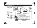 2
2
-
 3
3
-
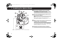 4
4
-
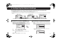 5
5
-
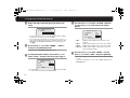 6
6
-
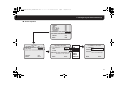 7
7
-
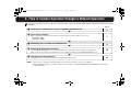 8
8
-
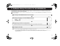 9
9
-
 10
10
-
 11
11
-
 12
12
-
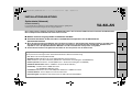 13
13
-
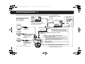 14
14
-
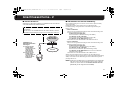 15
15
-
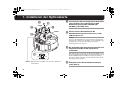 16
16
-
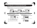 17
17
-
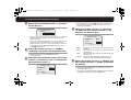 18
18
-
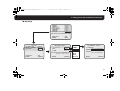 19
19
-
 20
20
-
 21
21
-
 22
22
-
 23
23
-
 24
24
-
 25
25
-
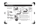 26
26
-
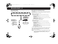 27
27
-
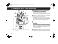 28
28
-
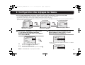 29
29
-
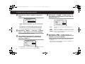 30
30
-
 31
31
-
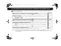 32
32
-
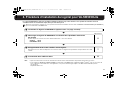 33
33
-
 34
34
-
 35
35
-
 36
36
-
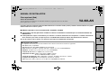 37
37
-
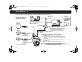 38
38
-
 39
39
-
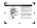 40
40
-
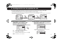 41
41
-
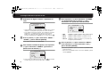 42
42
-
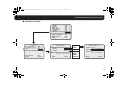 43
43
-
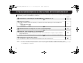 44
44
-
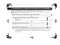 45
45
-
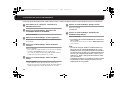 46
46
-
 47
47
-
 48
48
-
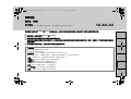 49
49
-
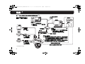 50
50
-
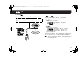 51
51
-
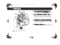 52
52
-
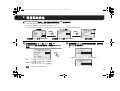 53
53
-
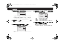 54
54
-
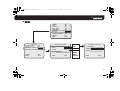 55
55
-
 56
56
-
 57
57
-
 58
58
-
 59
59
-
 60
60
-
 61
61
-
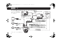 62
62
-
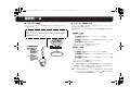 63
63
-
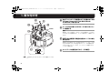 64
64
-
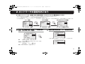 65
65
-
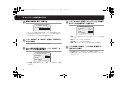 66
66
-
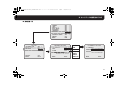 67
67
-
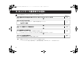 68
68
-
 69
69
-
 70
70
-
 71
71
-
 72
72


Sanyo VA-82LAN Guía de instalación
- Categoría
- Cámaras de seguridad
- Tipo
- Guía de instalación
En otros idiomas
- français: Sanyo VA-82LAN Guide d'installation
- English: Sanyo VA-82LAN Installation guide
- Deutsch: Sanyo VA-82LAN Installationsanleitung
- 日本語: Sanyo VA-82LAN インストールガイド