
www.magliner.com
ASSEMBLY INSTRUCTIONS
INSTRUCCIONES DE MONTAJE
Table of Contents:
Parts List ..................................... 2
Assembly Instructions ............2-5
Warranty Information .............. 6
Hand Truck
Índice de contenidos:
Lista de piezas ............................ 2
Instrucciones de montaje ........ 2-5
Información sobre la garantía .. 6
For safe, efficient product use, Magline recommends inspecting
equipment regularly and replacing damaged components immediately.
Para que su producto sea seguro y eficiente, Magline recomienda
inspeccionar el equipo regularmente, y cambiar los componentes
defectuoso inmediatamente.
Carretilla
de mano

TOOLS REQUIRED
• (2) 1/2” COMBINATION
WRENCH OR SOCKET
• (1) #3 PHILLIPS
SCREWDRIVER
• (1) HAMMER
• (1) PLIERS
• (1) 7/16” COMBINATION
WRENCH OR SOCKET
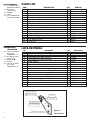
PARTS LIST
2
12 Frame (with black caps) 1 Varies
13 Handle 1 Varies
14 RH Wheel Bracket 1 210100
15 LH Wheel Bracket 1 210101
16 Nose Plate 1 Varies
17 18” Axle (16.81” for 815 wheels only) 1 22101 (or 22100)
18 Wheel 2 Varies
19 Side Channel Reinforcements 2 302001
Hardware Pack consists of items below: 301046 (or 301047)
20 Pin Coil Spring 1/8” x 1 1/8” 2 190104
21 Hex Head Screw 5/16"-18 x 2 1/4” 4 80017
10 Pan Head Screw 1/4"-20 x 1 1/2” 4 80105
11 Locknut 1/4"-20 4 80675
22 Locknut 5/16"-18 4 80676
24 5/8” Washer Thin 4 80707
25 5/8” Washer Thick 4 80705
23 Cotter Pin 2 81077
ITEM DESCRIPTION QTY. PART NO.
HERRAMIENTAS
NECESARIAS
• (2) LLAVE DE TUERCAS
O DE TUBO
COMBINADA 1/2”
• (1) DESTORNILLA DOR
PHILLIPS N
O
3
• (1) MARTILLO
• (1) ALICATES
• (2) LLAVE DE TUERCAS
O DE TUBO
COMBINADA 7/16”
LISTA DE PIEZAS
12 Bastidor (con capuchones negros) 1 Varias
13 Manivela 1 Varias
14 Agarradera de rueda derecha 1 210100
15 Agarradera de rueda izquierda 1 210101
16 Placa frontal 1 Varias
17 Eje 18” (16,81” sólo para ruedas 815) 1 22101 (ó 22100)
18 Rueda 2 Varias
19 Refuerzos del canal lateral 2 302001
Conjunto de piezas metálicas consiste de los siguientes artículos:
301046 (ó 301047)
20 Resorte espiral de puntas 1/8” x 1 1/8” 2 190104
21 Tornillo de cabeza hexagonal 5/16”-18 x 2 1/4” 4 80017
10 Tornillo de cabeza plana 1/4"-20 x 1 1/2" 4 80105
11 Contratuerca superior 1/4"-20 4 80675
22 Contratuerca superior 5/16"-18 4 80676
24 Arandela fina 5/8” 4 80707
25 Arandela gruesa 5/8” 4 80705
23 Pasador de chaveta 2 81077
ART
DESCRIPCIÓN
CTD
NÚM. PIEZA
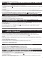
Agarradera de la rueda izquierda
Agujero inferior del eje
Ruedas de 8” de diámetro
Agujero superior del eje
Ruedas de 10” de diámetro
Mecanismo de bloqueo
(muesca)
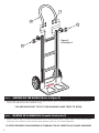
Left Hand Wheel Bracket
Lower Axle Hole
8” Diameter Wheels
Upper Axle Hole
10” Diameter Wheels
Lock Mechanism
(Groove)
Figure 1
Ilustración 1

STEP 1: 1. ASSEMBLE THE NOSE, WHEEL BRACKETS AND AXLE TO THE FRAME. (Refer
to Figure 2)
Use a workbench or table of convenient height and place all components in view and within reach.
a. Position the side channel reinforcements on the inside of the long legs of the frame making certain holes are aligned. (The reinforcements are the same length as the
frame legs.) Refer to Figure 2 (page 4). NOTE: If using extruded nose plate (see Figure 4) please follow the sub assembly instructions included in the nose plate kit then
continue to (b.).
b. While holding the reinforcements in place with each hand, slide the legs and reinforcements down and over the raised areas on the heel of the nose casting.
c. Insert the four (4) 5/16"-18 hex head bolts through the nose, reinforcements and the frame. This will prevent the parts from sliding out of position during
further assembly.
d. Position and attach the right hand wheel bracket to the outside of the frame leg, using two (2) 5/16”-18 hex head locknuts. Do Not Tighten The (2) Nuts At This Time!
Refer to Figure 2 (page 4).
e. Install first roll pin in the axle, tapping lightly with hammer to center the pin on the axle.
f. Insert the axle (the end with the roll pin in place) through the desired axle hole in the wheel bracket. NOTE: Rotate axle until roll pin "locks" into position in the
wheel bracket. The lower axle hole is for 8 inch diameter wheels and the upper axle hole is for 10 inch diameter wheels. Refer to Figure 1 (page 2).
•Note• Stair Climbers are optional. If used, please refer to the instructions provided with them now. If Stair Climbers ARE NOT used, continue with the
following general hand truck assembly instructions (Step g.).
g. Position and attach the left hand wheel bracket sliding it over the axle to the outside of the frame leg, using two (2) 5/16"-18 hex head locknuts to secure it. Do Not
Tighten The (2) Nuts At This Time! Refer to Figure 2 (page 4).
h. Install second wheel roll pin, tapping lightly with hammer to center.
i. Check all components for proper location at this time. Make any adjustments required.
j. Securely tighten nose and wheel bracket bolts at this time. (Tighten the 1/4"-20 screws to 50-60 in.-lbs. and 5/16"-18 hex head bolt to 120-140 in.-lbs.).
The following assembly sequence is recommended:
3
STEP 2: ASSEMBLING THE WHEELS. (Refer to Figure 2)
a. (FOR 815 WHEELS ONLY), Slide one (1) thick 5/8” washer on the axle. (Refer to Figure 2) (page 4) (FOR ALL OTHER WHEELS), Slide two (2) thick 5/8” washer on the
axle. (Refer to Figure 3) (page 4)
b. Slide a wheel on the axle....make sure the long hub portion is toward or next to the wheel bracket.
c. Slide one (1) thin 5/8” washer on the axle. (Refer to Figure 2) (page 4) NOTE: If required, a second thin washer is provided to shim the wheel for tighter fit.
d. Insert cotter pin through the hole on the end of the axle and spread the ends of the cotter pin apart by means of a regular screwdriver and a hammer.
• Repeat above assembly sequence for the second wheel.
PASO 1: 1. MONTE EL FRONTAL, LAS AGARRADERAS DE RUEDA Y EL EJE AL BASTIDOR.
(CONSULTE LA ILUSTRACIÓN 2)
1. Utilice un banco ajustador o mesa de altura apropiada y coloque todos los componentes a la vista y al alcance.
a. Coloque los refuerzos del canal lateral en el interior de los soportes largos del bastidor asegurándose de que ciertos agujeros estén alineados.
(los refuerzos son de la misma longitud que los soportes del bastidor.) Consulte la ilustración 2 (página 4). NOTA: Si se utiliza una placa frontal extruida
(véase ilustración 4) siga las instrucciones de submontaje incluida en el kit de la placa frontal, luego siga con (b.).
b. Mientras coloca los refuerzos con cada mano, deslice hacia abajo los soportes y los refuerzos y sobre las zonas elevadas encima del lomo de la pieza fundida
del frontal.
c. Inserte los cuatro (4) pasadores de cabeza hexagonal 5/16”-18 a través del frontal, los refuerzos y el bastidor. Esto evitará que las piezas se desplacen de posición
durante el montaje posterior.
d. Coloque y acople la agarradera de rueda derecha hacia fuera del soporte del bastidor utilizando dos (2) contratuercas de cabeza hexagonal 5/16”-18. No apriete
las (2) tuercas todavía Consulte la ilustración 2 (página 4).
e. Instale el primer pasador de giro en el eje y golpeando ligeramente con un martillo para centrar el pasador sobre el eje.
f. Inserte el eje (el extreme con el pasador de giro colocado) a través del agujero del eje deseado en la agarradera de rueda. NOTA: Gire el eje hasta que el pasador
de giro se enclave en la agarradera de rueda. El agujero del eje inferior es para ruedas de 8 pulgadas de diámetro y el agujero del eje superior es para ruedas de
10 pulgadas de diámetro. Consulte la ilustración 1 (página 2).
•Nota• Las carretillas elevadoras son opcionales. Si se utilizan, remítase ahora a las instrucciones de montaje que se suministraron con ellas. Si NO se utilizan
carretillas elevadoras continúe con las instrucciones generales siguientes de montaje de la carretilla de mano (paso g.).
g. Coloque y acople la agarradera de rueda izquierda deslizándola sobre el eje hacia fuera del soporte del bastidor utilizando dos (2) contratuercas de cabeza
hexagonal 5/16”-18 para fijarla. ¡No apriete las (2) tuercas todavía! Consulte la ilustración 2 (página 4).
h. Instale el segundo pasador giratorio de rueda golpeando ligeramente con un martillo para centrarlo.
i. Compruebe ahora la correcta colocación de todos los componentes. Realice todos los ajustes necesarios.
j. Ahora apriete firmemente el frontal y los pasadores de la agarradera de rueda. (Apriete los tornillos 1/4”-20 con 50-60 in.-lbs. y el pasador de cabeza hexagonal
5/16”-18 con 120-140 in.-lbs.).
Se recomienda la siguiente secuencia de montaje:
PASO 2: MONTAJE DE LAS RUEDAS. (CONSULTE LA ILUSTRACIÓN 2)
a. (PARA RUEDAS 815 EXCLUSIVAMENTE), Deslice una (1) arandela gruesa 5/8” sobre el eje. (Consulte la ilustración 2) (página 4). (PARA TODAS LAS DEMÁS RUEDAS),
Deslice dos (2) arandelas gruesas 5/8” sobre el eje. (Consulte la ilustración 4) (página 4).
b. Deslice una rueda sobre el eje....asegúrese de que la parte larga del buje está hacia la agarradera de rueda o próxima a ésta.
c. Deslice una (1) arandela fina 5/8” sobre el eje. (Consulte la ilustración 2) (página 4) NOTA: Por si se necesita, se proporciona una segunda arandela fina para ajustar
la rueda para un montaje par tenso.
d. Inserte el pasador de chaveta en el agujero al final del eje y extienda los extremos del pasador de chaveta mediante un destornillador corriente y un martillo.
• Repita la anterior secuencia de montaje para la siguiente rueda.

16
19
19
14
21
15
12
22
22
18
18
17
20
25
24
26
26
23
23
18
18
17
20
25
24
25
24
14
15
23
23
22
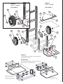
“Flush” Heel Position
Posición del lomo a nivel
“Recessed” Heel Position
*Only for noses with cutouts.
Posición de lomo empotrado
*Sólo para frontales con muescas
Figure 2
(for 8” wheels)
4
Figure 4
For Extruded Noses please follow instructions
provided in nose kit.
Figure 3
(for 10” wheels)
Ilustración 3
Ilustración 2
Ilustración 4
Para frontales extruidos, siga las instrucciones
indicadas para el kit del frontal.

4
10
10
13
11
STEP 3: ASSEMBLING THE HANDLE (Refer to Figure 5)
a. Place black frame caps on frame. Position the handle between the frame rails and line up holes. Fasten with four (4) 1/4”-20 pan head screws and hex head
locknuts. Securely tighten (1/4”-20 screws to 50-60 in.-lbs. torque).
YOU ARE NOW READY TO PUT YOUR MAGLINER HAND TRUCK TO WORK.
Figure 5
Ilustración 5
5
PASO 3: MONTAJE DE LA MANIVELA (Consulte ilustración 5)
a. Coloque los capuchones negros en el bastidor. Coloque la manivela entre los carriles del bastidor y alinee los agujeros. Asegure con cuatro tornillos 1/4”-20 de
cabeza plana y cuatro contratuercas de cabeza hexagonal. Apriete firmemente (tornillos 1/4” con par de apriete 50-60 in.-lbs.)
YA ESTÁ PREPARADO PARA EMPEZAR A TRABAJAR CON SU CARRETILLA DE NANO MAGLINER

Date of Purchase Record
Fax this form to Magline, Inc. 1-800-968-7504.
Please Print All Information Clearly
Purchase Date: ___________________________________________________________________
Company Name: _________________________________________________________________
Contact Name: __________________________________________________________________
Title: ___________________________________________________________________________
E-mail: __________________________________________________________________________
Address: _________________________________________________________________________
City:_______________________________ State:________ Postal Code: ___________________
Country: _________________________________________________________________________
Phone: _________________________________________________________________________
Fax: _____________________________________________________________________________
Purchased From: _________________________________________________________________
Product Purchased: _______________________________________________________________
Model Number: _________________________________________________________________
No. of Routes: ___________________________________________________________________
Business Type:
_____ Beer _____ Soft Drink _____ Healthcare
_____ Food Service _____ Parcel
_____ Bakery _____ Snacks
_____ Vending _____ Bottled Water
_____ Other:__________________________________________
Fecha de registro de compra
Envíe por fax este formulario a Magline, Inc. 1-800-968-7504
o visite el sitio web www.magliner.com. Imprima toda la
información con claridad
Fecha de compra: ________________________________________________________________
Nombre de la empresa: ___________________________________________________________
Persona de contacto: _____________________________________________________________
Cargo: __________________________________________________________________________
Correo electrónico: _______________________________________________________________
Dirección: _______________________________________________________________________
Ciudad:_________________________ Estado:________ Código postal: ___________________
País: ____________________________________________________________________________
Teléfono: ________________________________________________________________________
Fax: _____________________________________________________________________________
Comprado desde: ________________________________________________________________
Producto comprado: _____________________________________________________________
Número de modelo: ______________________________________________________________
Núm. de rutas: ___________________________________________________________________
Clase de actividad:
_____ Cerveza _____ Refrescos _____ Salud
_____ Servicio de alimentos _____ Paquetería
_____ Panadería _____ Snacks
_____ Vending _____ Agua embotellada
_____ Otros __________________________________________
WARRANTY INFORMATION
Magline One-Year Limited Warranty
Magliner products have a one (1) year warranty from the date of
purchase against defects in workmanship or material.
Any part or component, except items covered by warranties of other
manufacturers, returned to the factory or service center freight prepaid
by the owner, found upon examination by Magline, Inc. to be defective
or the result of improper workmanship by the factory will be repaired
or replaced without charge and returned to the owner freight prepaid
by Magline, Inc.
Alterations of Magliner products void any warranty or liability on the
part of Magline, Inc. Magline does not guarantee product capacity if
alterations are made.
INFORMACIÓN SOBRE LA GARANTÍA
Garantía limitada de un año Magline
Los productos Magline tienen una garantía de un (1) año desde la
fecha de compra para trabajos de reparación o material.
Cualquier parte o componente, excepto los artículos cubiertos por
las garantías de otros fabricantes, devueltos a la planta o al centro
de servicio con el transporte prepagado por el propietario, que
Magline considere después de su comprobación como defectuosos
o de elaboración inadecuada por parte de la planta se repararán o
sustituirán sin cargo y será devuelto al propietario con portes pagados
por Magline Inc.
Las modificaciones de los productos Magliner eximen a Magline Inc. de
toda garantía o responsabilidad. Magline no garantiza la capacidad del
producto si se realizan transformaciones.
B5568 Revised 7/11 © Copyright 2008-2011 Magline, Inc.
En 1947, Magline Inc.
introdujo las primeras carretillas de mano ligeras
Magliner en las empresas americanas.
Hoy en día, nuestras soluciones de entrega en ruta se han expandido
mundialmente. Encontrará la familia Magline de carretillas de mano, rampas y
productos de muelle en las operaciones de entrega en ruta en todo el mundo.
El nombre Magliner es sinónimo de confianza desde hace más de medio siglo.
En material de rendimiento, durabilidad y seguridad, descubrirá lo que millones
de profesionales de reparto en rutas en todo el mundo ya saben – ningún otro
equipo es comparable a un Magliner.
¡Gracias por su compra y bienvenido a la familia Magliner!
In 1947, Magline, Inc.
introduced the first light weight Magliner hand
trucks to American businesses.
Today, our route delivery solutions have expanded -- globally. You’ll find
Magline’s family of hand trucks, ramps, and dock products in route delivery
operations all over the world.
People have trusted the Magline name for more than half a century. For
performance, durability, and safety, you’ll discover what millions of route
delivery professionals around the world already know – no other equipment
measures up to a Magliner.
Thank you for your purchase and welcome to the Magliner family!
Magline, Inc.
1205 W. Cedar Street • Standish, MI 48658 USA
1-800-MAGLINE (624-5463) • (989) 512-1000 (fuera de EE.UU. y Canad
á
)
www.magliner.com
Magline, Inc.
1205 W. Cedar Street • Standish, MI 48658 USA
1-800-MAGLINE (624-5463) • (989) 512-1000 (outside U.S. & Canada)
www.magliner.com
6
-
 1
1
-
 2
2
-
 3
3
-
 4
4
-
 5
5
-
 6
6


En otros idiomas
Documentos relacionados
Otros documentos
-
Gemini 301080 Manual de usuario
-
Milwaukee 8955 Manual de usuario
-
Cosco TR305 Manual de usuario
-
 Eddie Bauer Alpine 3 Manual de usuario
-
-
-
-
World Marketing of America DuraHeat DFA-210C Manual de usuario
-
 American Lawn Mower Co. 1815-18 El manual del propietario
-
DeWalt DWE74911 Manual de usuario

