Faber Tratto Isola 36 SSV with VAM Guía de instalación
- Categoría
- Campanas de cocina
- Tipo
- Guía de instalación

TRATIS36SSV
TRATTO IS 36"
Installation Instructions
Use and Care Information
Instructions d'installation
Utilisez et d'entretien
Instrucciones de instalación
Información de uso y cuidado

2
READ AND SAVE THESE INSTRUCTIONS BEFORE YOU START
INSTALLING THIS RANGEHOOD
WARNING: - TO REDUCE THE RISK OF A RANGE TOP GREASE FIRE:
a) Never leave surface units unattended at high settings. Boilovers cause smoking and
greasy spillovers that may ignite. Heat oils slowly on low or medium setting.
b)AlwaysturnhoodONwhencookingathighheatorwhenambeingfood(i.e.Crepes
Suzette, Cherries Jubilee, Peppercorn Beef Flambé).
c) Clean ventilating fans frequently. Grease should not be allowed to accumulate on fan
orlter.
d) Use proper pan size. Always use cookware appropriate for the size of the surface element.
WARNING: - TO REDUCE THE RISK OF INJURY TO PERSONS IN THE EVENT OF A
RANGE TOP GREASE FIRE, OBSERVE THE FOLLOWING*:
a)SMOTHERFLAMESwithaclose-ttinglid,cookiesheet,ormetaltray,thenturnofftheburner.
BECAREFULTOPREVENTBURNS.IftheamesdonotgooutimmediatelyEVACUATE
AND CALL THE FIRE DEPARTMENT.
b) NEVER PICK UP A FLAMING PAN - You may be burned.
c) DO NOT USE WATER, including wet dishcloths or towels - a violent steam explosion will
result.
d) Use an extinguisher ONLY if:
1. You know you have a Class ABC extinguisher, and you already know how to operate it.
2. Thereissmallandcontainedintheareawhereitstarted.
3. Theredepartmentisbeingcalled.
4. Youcanghttherewithyourbacktoanexit.
* Based on "Kitchen Firesafety Tips" published by NFPA
WARNING - TO REDUCE THE RISK OF FIRE OR ELECTRIC SHOCK, do not use this
fan with any solid-state speed control device.
WARNING - TO REDUCE THE RISK OF FIRE, ELECTRICAL SHOCK, OR INJURY TO
PERSONS, OBSERVE THE FOLLOWING:
1. Use this unit only in the manner intended by the manufacturer. If you have any
questions, contact the manufacturer.
2. Before servicing or cleaning unit, switch power off at service panel and lock the
service disconnecting means to prevent power from being switched on acciden-
tally. When the service disconnecting means cannot be locked, securely fasten a
prominent warning device, such as a tag, to the service panel.
CAUTION: For General Ventilating Use Only. Do Not Use To Exhaust Hazardous or
Explosive Materials and Vapors.
WARNING - TO REDUCE THE RISK OF FIRE, ELECTRICAL SHOCK, OR INJURY TO
PERSONS, OBSERVE THE FOLLOWING:
1. InstallationWorkAndElectricalWiringMustBeDoneByQualiedPerson(s)InAccor-
dance With All Applicable Codes And Standards, Including Fire-Rated Construction.
2. Sufcientairisneededforpropercombustionandexhaustingofgasesthrough
theue(chimney)offuelburningequipmenttopreventbackdrafting.Followthe
heating equipment manufacturer's guideline and safety standards such as those
publishedbytheNationalFireProtectionAssociation(NFPA),andtheAmerican
SocietyforHeating,RefrigerationandAirConditioningEngineers(ASHRAE),and
the local code authorities.

3
3. When cutting or drilling into wall or ceiling, do not damage electrical wiring and
other hidden utilities.
4. Ducted fans must always be vented to the outdoors.
ALL WALL AND FLOOR OPENINGS WHERE THE RANGEHOOD IS INSTALLED MUST
BE SEALED.
This rangehood requires at least 24" of clearance between the bottom of the rangehood
and the cooking surface or countertop. This hood has been approved by UL at this distance
from the cooktop.
This minimum clearance may be higher depending on local building codes. For gas cooktops
and combination ranges, a minimum of 30" is recommended and may be required.
Overhead cabinets on both sides of this unit must be a minimum of 18" above the cooking surface
or countertop. Consult the cooktop or range installation instructions given by the manufacturer
before making any cutouts.
MOBILE HOME INSTALLATION The installation of this rangehood must conform to the
Manufactured Home Construction and Safety Standards, Title 24 CFR, Part 3280 (formerly
Federal Standard for Mobile Home Construction and Safety, Title 24, HUD, Part 280). See
Electrical Requirements.
• Venting system MUST terminate outside the home.
• DO NOT terminate the ductwork in an attic or other enclosed space.
• DO NOT use 4" laundry-type wall caps.
• Flexible-type ductwork is not recommended.
• DO NOT obstruct the ow of combustion and ventilation air.
• Failure to follow venting requirements may result in a re.
WARNING
!
VENTING REQUIREMENTS
Determine which venting method is best for your application. Ductwork can extend either through the
wall or the roof.
The length of the ductwork and the number of elbows should be kept to a minimum to provide efcient
performance. The size of the ductwork should be uniform. Do not install two elbows together. Use
duct tape to seal all joints in the ductwork system. Use caulking to seal exterior wall or oor opening
around the cap.
Flexible ductwork is not recommended. Flexible ductwork creates back pressure and air turbulence
that greatly reduces performance.
Make sure there is proper clearance within the wall or oor for exhaust duct before making cutouts.
Do not cut a joist or stud unless absolutely necessary. If a joist or stud must be cut, then a supporting
frame must be constructed.
WARNING - To Reduce The Risk Of Fire, Use Only Metal Ductwork.
CAUTION-Toreduceriskofreandtoproperlyexhaustair,besuretoductairoutside–Do
not vent exhaust air into spaces within walls or ceilings or into attics, crawl spaces, or garages.

4
ELECTRICAL REQUIREMENTS
A 120 volt, 60 Hz AC-only electrical supply is required on a separate 15 amp fused circuit. A time-delay
fuse or circuit breaker is recommended. The fuse must be sized per local codes in accordance with
the electrical rating of this unit as specied on the serial/rating plate located inside the unit near the eld
wiring compartment.
ELECTRICAL INSTALLATION WITH WIRING BOX
THIS UNIT MUST BE CONNECTED WITH COPPER WIRE ONLY. Wire sizes must conform to the
requirements of the National Electrical Code, ANSI/NFPA 70 - latest edition, and all local codes and
ordinances. Wire size and connections must conform with the rating of the appliance. Copies of the
standard listed above may be obtained from:
National Fire Protection Association
Batterymarch Park
Quincy, Massachusetts 02269
This appliance should be connected directly to the fused disconnect (or circuit breaker) through
exible, armored or nonmetallic sheathed copper cable. Allow some slack in the cable so the
appliance can be moved if servicing is ever necessary. A UL Listed, 1/2" conduit connector must
be provided at each end of the power supply cable (at the appliance and at the junction box).
When making the electrical connection, cut a 1 1/4" hole in the wall. A hole cut through wood
must be sanded until smooth. A hole through metal must have a grommet.
• Electrical ground is required on this rangehood.
• If cold water pipe is interrupted by plastic, nonmetallic gaskets or other materials, DO
NOT use for grounding.
• DO NOT ground to a gas pipe.
• DO NOT have a fuse in the neutral or grounding circuit. A fuse in the neutral or
grounding circuit could result in electrical shock.
• Check with a qualied electrician if you are in doubt as to whether the rangehood is
properly grounded.
• Failure to follow electrical requirements may result in a re.
WARNING
!
StateofCaliforniaProposition65Warning(USonly)
WARNING
This product contains chemicals known to the State of California to cause cancer and birth
defects or other reproductive harm.
For more information go to www.P65Warnings.ca.gov

5
RANGEHOOD DIMENSIONS
Min. 24" Min. 30"

6
10
MAIN PARTS
Components
Ref. Qty. Product Components
1 1 Hood Body, complete with: Con-
trols, Light, Filters, Blower.
2 1 Telescopic Chimney comprising:
2.1 1 Upper Section
2.2 1 Lower Section
7.1 1 Telescopic frame complete with
extractor, consisting of:
7.1a 1 Upper frame
7.1b 1 Lower frame
10 1 Damper ø 5 7/8"
24 1 Junction Box
Ref. Qty. Installation Components
12f 2 Screws 3/16" x 9/16"
12c 2 Screws 1/8" x 1/4"
12e 4 Screws 1/8" x 3/8"
12q 4 Screws 1/4" x 9/16"
21 1 Drilling template
22 4 1/4" int. dia washers
Qty. Documentation
1 Instruction Manual
1
2.2
2.1
21
7.1
12q
22
12c
12e
12f
24
7.1a
7.1b
Available Accessories
-HighCeilingKitthatreplacestheupperue.-sku#HIGH2.
- Ductless Kit - Includes Ductless Diverter, Charcoal Filters, Lower chimney with vent
grates-sku#DUCT2
-ActivatedCharcoalFilterAccessory-sku#FILTER2
- Wireless RemoteControlAccessory-REMCTRL2
Parts needed
-6"RoundMetalductwork

7
Choose your ducting method
Non Ducted - RecirculationDucted Venting Installation
RequiresDuctlessAccessoryKit
(purchased separately)
6 "

8
1
Putathick,protectivecoveringovercooktop,
set-in range or countertop to protect from
damage or dirt.
Determineandclearlymarkwithapencilonthe
ceiling where the rangehood will be installed.
A template 21 for mounting the support is
supplied in the carton with the support. Use
thistemplatetomarkholesfor
support on the ceiling.
Determineand make necessary cutsforthe
ductwork.Theductopeningisshownonthe
mounting template. Install
ductworkbeforemountingthehood.
Determine the proper location for the Power
Supply Cable as indicated on the template.
Use a 1 1/4" Drill Bit to make this hole. Run
thePowerSupplyCable.Usecaulkingtoseal
around the hole.
A knockout for threading through the Power
Supply from the ceiling is located on the top
of the frame. Do not connect the Power Cable
to the Wiring Box or power up the hood at this
time.Runenoughpowercablefromtheceiling
to reach the wiring box on the hood.
Ø 10 mm
x4
21
1 1/4"
Donotmakeanycutoutsuntilyouhavedecidedwhetherthisinstallationwillbeductedor
non-duct and then plan accordingly.
DUE TO THE SIZE AND
WEIGHT OF THIS RANGE-
HOOD, THE SUPPORT MUST
BE FIRMLY ATTACHED TO
THE CEILING. For plaster or
sheet rock ceiling, the support
must be attached to the joists.
If this is not possible, a support
structure must be built behind
the plaster or sheet rock. The
manufacturer assumes no re-
sponsibility forinjury or damage
caused by improper installa-
tions.
WARNING
!

9
Chimney Flues Must Be Removed Before Installing the Hood
2
3
4
Loosen the two screws fastening the lower chimney
and remove this from the lower frame.
If you need to adjust the height of the frame,
proceed as follows:
• Unfasten the metric screws joining the two
columns, located at the sides of the frame
(1,2,3,4,5,6).
• Adjust the frame to the height required, then
ret all the screws removed as above.
Loosen the two screws fastening the upper chimney
and remove this from the upper frame.
1
4
MIN
740
mm
MAX
940
mm
2
3
5
6

10
14. REMOVING THE MIDDLE TRESTLE COMPONENT
NOTE: The chimney structure can reduce down to a 27 " minimum height. To reduce the height,
the middle section of the support structure needs to be removed.
Out of the box, the minimum chimney length is 32 ".
Insure the the installation process outlined in the U&C is followed and there is sufficient stability with the
middle section removed.
5
NOTE: The chimney structure can reduce down to a 27 " minimum height. To reduce the height,
the middle section of the support structure needs to be removed.
Out of the box, the minimum chimney length is 32 ".
Insure the the installation process outlined in the U&C is followed and there is sufcient stability with the
middle section removed.
REMOVING THE MIDDLE TRESTLE COMPONENT
6
After the regulation for height adjustment, insert
the upper chimney stack from above, and leave it
running free on the frame.
Upper Flue Must Be In Place Before Proceeding

11
7
Install Damper that is included with the Hood before
connecting to the ductwork.
Only for Ducted Venting Installation
8
Now take either your wood screws or bolts
depending on your set-up and screw all four
into the pilot holes and leave 1/4" of the
heads exposed.
Next install a UL or CSA listed strain relief
in the wiring box so that the screws can
be tightened after the chimney support is
attached to the ceiling.
Now lift the chimney support into it's nal
position and feed the electrical supply through
the strain relief.
Next position the chimney support so that
the large end of the keyhole slots are over
the ceiling attachment screws or bolts. Then
push the chimney support so that the bolts
are in the neck of the slots. Tighten all four
screws or bolts securely.
• The frame mountings must be secure to
withstand the weight of the hood and any
stresses caused by the occasional side
thrust applied to the device. On completion,
check that the base is stable, even if the
frame is subjected to bending.
• In all cases where the ceiling is not
strong enough at the suspension point,
the installer must provide strengthening
using suitable plates and backing pieces
anchored to the structurally sound parts.

12
Installation of wiring
connection
Remove the cover from the
eld wiring compartment.
DO NOT turn on the power until
installation is complete!
Connect the Power Supply
Cable to the rangehood.
Connect the Green (Green and
Yellow) ground wire under the
Green grounding screw. Attach
the White lead of the power
supply to the White lead of the
rangehood with a twist-on type
wire connector.
Attach the Black lead of the
power supply to the Black lead
of the rangehood with a twist-
on type wire connector.
Replace the eld wiring compart-
ment cover and the grease lters.
A. Home power supply cable
B. Black wires
C. UL listed wire connectors
D. White wires
E. Green (or bare) ground wire from home power supply connected to green ground screw
F. Range hood power supply cable
G. Range hood power supply cable connected to green ground screw
Version 02/12 - Page 8
FIGURE 13
MAKE THE ELECTRICAL CONNECTION
Remove the cover from the eld wiring compartment. (SEE
FIGURE 11) DO NOT turn on the power until installation is
complete! Connect the Power Supply Cable to the rangehood.
Connect the Green (Green and Yellow) ground wire under the
Green grounding screw. Attach the White lead of the power
supply to the White lead of the rangehood with a twist-on type
wire connector. Attach the Black lead of the power supply
to the Black lead of the rangehood with a twist-on type wire
connector.
1. The UPPER CHIMNEY
COVER (C in FIGURE 13)
attaches to the top of the
support structure using two
screws provided (G in FIGURE
13). If using the High Ceiling
Chimney Kit, use the UPPER
CHIMNEY COVER supplied
with the kit. Slide up and
attach the UPPER CHIMNEY
COVER.
2. Attach the duct work to the
DAMPER (M in FIGURE 1).
Make sure to seal all joints with
duct tape to prevent leaks.
3. The LOWER CHIMNEY
COVER (B in FIGURE 13)
attaches using two screws
provided (G in FIGURE 13).
Install the LOWER CHIMNEY
COVER by sliding it up over
the support and the UPPER
CHIMNEY COVER.
For ductless installations, line up the DUCTLESS DIVERTER
EXTENSIONS HORIZONTAL (B in FIGURE 12) with the holes
in the LOWER CHIMNEY COVER (D in FIGURE 12) and snap
in the VENT GRIDS (C in FIGURE 12).
INSTALLING THE RANGEHOOD
A. Home power supply cable
B. Black wires
C. UL listed wire connectors
D.White wires
E. Green (or bare) ground wire from home power supply
connected to green ground screw
F. Range hood power supply cable
G.Range hood power supply cable connected to green
ground screw
FIGURE 11
Ductless installations require
a Ductless Conversion
Kit whose components are
pictured in FIGURE 12. Do
not use the DAMPER (M
in FIGURE 1) for ductless
installations. The LOWER
CHIMNEY COVER (B
in FIGURE 1) should be
discarded and replaced by
the new one with holes from
the Ductless Conversion Kit
(D in FIGURE 12).
As indicated in FIGURE
12, place the DUCTLESS
DIVERTER (A) over the
exhaust opening of the EASY
CUBE (E). Fit the DUCTLESS
DIVERTER EXTENSIONS
HORIZONTAL (B) into the
DIVERTER (A).
FIGURE 12
FOR DUCTLESS INSTALLATIONS
9
Position the upper chimney section and x the upper
part to the frame using the 2 screws removed previously.
8

13
11
Similarly, position the lower chimney section and x the lower part to the frame using the 2 screws
removed previously.
10
Only For Ductless Installations
Ductless installations require a Ductless
Conversion Kit whose components are
pictured in FIGURE 12.
Do not use the DAMPER for ductless
installations. The LOWER CHIMNEY COVER
should be discarded and replaced by the
new one with holes from the Ductless
Conversion Kit (D in FIGURE 12).
As indicated in FIGURE 12, place the
DUCTLESS DIVERTER (A) over the exhaust
opening of the EASY CUBE (E). Fit the
DUCTLESS DIVERTER EXTENSIONS
HORIZONTAL (B) into the DIVERTER (A).
Version 02/12 - Page 8
FIGURE 13
MAKE THE ELECTRICAL CONNECTION
Remove the cover from the eld wiring compartment. (SEE
FIGURE 11) DO NOT turn on the power until installation is
complete! Connect the Power Supply Cable to the rangehood.
Connect the Green (Green and Yellow) ground wire under the
Green grounding screw. Attach the White lead of the power
supply to the White lead of the rangehood with a twist-on type
wire connector. Attach the Black lead of the power supply
to the Black lead of the rangehood with a twist-on type wire
connector.
1. The UPPER CHIMNEY
COVER (C in FIGURE 13)
attaches to the top of the
support structure using two
screws provided (G in FIGURE
13). If using the High Ceiling
Chimney Kit, use the UPPER
CHIMNEY COVER supplied
with the kit. Slide up and
attach the UPPER CHIMNEY
COVER.
2. Attach the duct work to the
DAMPER (M in FIGURE 1).
Make sure to seal all joints with
duct tape to prevent leaks.
3. The LOWER CHIMNEY
COVER (B in FIGURE 13)
attaches using two screws
provided (G in FIGURE 13).
Install the LOWER CHIMNEY
COVER by sliding it up over
the support and the UPPER
CHIMNEY COVER.
For ductless installations, line up the DUCTLESS DIVERTER
EXTENSIONS HORIZONTAL (B in FIGURE 12) with the holes
in the LOWER CHIMNEY COVER (D in FIGURE 12) and snap
in the VENT GRIDS (C in FIGURE 12).
INSTALLING THE RANGEHOOD
A. Home power supply cable
B. Black wires
C. UL listed wire connectors
D.White wires
E. Green (or bare) ground wire from home power supply
connected to green ground screw
F. Range hood power supply cable
G.Range hood power supply cable connected to green
ground screw
FIGURE 11
Ductless installations require
a Ductless Conversion
Kit whose components are
pictured in FIGURE 12. Do
not use the DAMPER (M
in FIGURE 1) for ductless
installations. The LOWER
CHIMNEY COVER ( B
in FIGURE 1) should be
discarded and replaced by
the new one with holes from
the Ductless Conversion Kit
(D in FIGURE 12).
As indicated in FIGURE
12, place the DUCTLESS
DIVERTER (A) over the
exhaust opening of the EASY
CUBE (E). Fit the DUCTLESS
DIVERTER EXTENSIONS
HORIZONTAL (B) into the
DIVERTER (A).
FIGURE 12
FOR DUCTLESS INSTALLATIONS

14
12
Screw the 2 screws 12f half way into the holes provided in the sides of the bottom of the frame.
Remove the grease lters from the hood canopy.
Remove any activated charcoal lters.
Lift the hood canopy and engage the screws 12f in the slots as far as they will go.
Working from below, x the
hood canopy to the frame
where indicated, using the 4
screws 12q and 4 washers 22
provided, then tighten all the
screws securely.
I
I
T[
[
Attachment of Hood Canopy

15
13
Connect the control connector Cmd.
Place the connectors in the junction box 24 and
close it using the 4 screws provided.
14
12c x 2
Fix the junction box
to the hood body
using the 2 screws
12c provided.
H
Make the Internal Electrical Connection

16
14
For Non-Ducted Recirculation
Option
RequiredActivatedCharcoalFilter
Accessory-sku#-FILTER2
(purchased separately)
Attach a
charcoal
lterinthe
correct
position and
blockitby
thexing
hooksas
shown.
Unlockthexinghooks(towardsthebackofthe
insert hood) to remove.
Reinstall the grease lters
from the hood canopy.
15

17
USE AND CARE INFORMATION
T1 T2 T3 T4 L
LT1 T2 T3 T4
For Best Results
Startthe rangehood severalminutes before cookingto developproperairow.Allowthe
rangehoodtooperateforseveralminutesaftercookingiscompletetoclearallsmokeand
odorsfromthekitchen.
T1.Fanoffbutton:turntheblowerOff.Thefancanbeoperatedbypressinganyofthefansettingbuttons.
Holddownthisbuttonfor2secondstoactivateDelayofffunctionwhichwillkeepthefanonfor15
minutes and automatically shut off.
T2. Fan settings buttons: Low speed.
T3. Fan settings buttons: Medium speed.
T4. Fan settings buttons: High speed / Intensive speed.
Hold down the button for 2 seconds to activate the intensive speed, which is timed to run for 10
minutes. At the end of this time it will automatically return to the speed set before.Suitable to deal
withmaximumlevelsofcookingfumes.
L. Light button: On/Off switch for the lights.
NOTE:IfyourproducthashadaCFMadjustment,refertotheCFMadjustmentmanualfortheinfor-
mation. Some motor speeds or functions may be reduced.

18
Cleaningmetalgreaselters
Theltersmustbecleanedevery2months
ofoperation,ormorefrequentlyforparticu-
larly heavy usage, and can be washed in a
dishwasher.
• RemovetheFiltersoneatatime,pushing
themtowardsthebackoftheunitandatthe
same time pulling downward.
• Wash the Filters without bending them, and
leave them to dry completely before replac-
ing.(Ifthesurfaceofthelterchangescolour
as time goes by, this will have absolutely no
effectontheefciencyofthelteritself.)
• Replace, taking care to ensure that the
handle faces forwards.
• No water canbe present in ltersbefore
installingbackinhood.
Replacing Activated Charcoal Filter
Thelterisnotwashableandcannotberegener-
ated, and must be replaced approximately every 4
monthsofoperation,ormorefrequentlyforparticu-
larly heavy usage.
• RemovetheFiltersoneatatime,pushingthem
towardsthebackoftheunitandatthesametime
pulling downward.
• Removethesaturatedcharcoallterbyreleasing
thexinghooks.
• Fitthenewlterandfastenitinitscorrectposition.
• Replace,takingcaretoensurethatthehandle
faces forwards. "When used in recirculation
mode,toReducetheRiskofFireandShock
useonlyconversionkitModelFILTER2".
Lighting Unit
• LED lights must be replaced by Faber factory authorized
service.

19
Wiring Diagram
991.0439.886 H90-305
D002531_01
991.0439.886 H90-305
D002531_01

20
January 4, 2016
FABER CONSUMER WARRANTY & SERVICE
All Faber products are warranted against any defect in materials or workmanship for the original purchaser
for a period of 1 year from the date of original purchase (requires proof of purchase). This warranty covers
labor and replacement parts. Faber, at its option, may repair or replace the product or components
necessary to restore the product to good working condition. To obtain warranty service, contact the dealer
from whom you purchased the range hood, or the local Faber distributor. If you cannot identify a local Faber
distributor, contact us at (508) 358-5353 for the name of a distributor in your area.
The following is not covered by Faber's warranty:
1. Service calls to correct the installation of your range hood, to instruct you how to use your range hood, to
replace or repair house fuses or to correct house wiring or plumbing.
2. Service calls to repair or replace range hood light bulbs, fuses or filters. Those consumable parts are
excluded from warranty coverage.
3. Repairs when your range hood is used for other than normal, single-family household use.
4. Damage resulting from accident, alteration, misuse, abuse, fire, flood, acts of God, improper installation,
installation not in accordance with electrical or plumbing codes or Faber documentation, or use of products
not approved by Faber.
5. Replacement parts or repair labor costs for units operated outside the United States or Canada, including
any non-UL or C-UL approved Faber range hoods.
6. Repairs to the hood resulting from unauthorized modifications made to the range hood.
7. Expenses for travel and transportation for product service in remote locations and pickup and delivery
charges. Faber range hoods should be serviced in the home.
THIS WARRANTY DOES NOT ALLOW RECOVERY OF INCIDENTAL OR CONSEQUENTIAL DAMAGES, INCLUDING, WITHOUT
LIMITATION, DIRECT, INDIRECT, INCIDENTAL, SPECIAL OR CONSEQUENTIAL DAMAGES, PERSONAL INJURY/WRONGFUL
DEATH OR LOST PROFITS FABER WARRANTY IS LIMITED TO THE ABOVE CONDITIONS AND TO THE WARRANTY PERIOD
SPECIFIED HEREIN AND IS EXCLUSIVE. EXCEPT AS EXPRESSLY SPECIFIED IN THIS AGREEMENT, FABER DISCLAIMS ALL
EXPRESS OR IMPLIED CONDITIONS, REPRESENTATIONS, AND WARRANTIES INCLUDING, WITHOUT LIMITATION, ANY
IMPLIED WARRANTIES OF MERCHANTABILITY OR FITNESS FOR A PARTICULAR PURPOSE
.
This warranty gives you specific legal rights that may vary from state to state.
Model#: ______________________________ Serial #: _____________________________

21
VEUILLEZ LIRE ET CONSERVER LA PRÉSENTE NOTICE AVANT DE
COMMENCER L'INSTALLATION DE LA HOTTE DE CUISINE
AVERTISSEMENT : POUR RÉDUIRE LE RISQUE D'UN FEU DE GRAISSE SUR LA TABLE DE
CUISSON:
a) Ne laissez jamais sans surveillance les éléments de la surface de cuisson à température élevée.
Les bouillonnements excessifs peuvent provoquer de la fumée et les débordements de graisse
peuvents'enammer.L'huiledoitêtrechaufféelentement,àunetempératurebasseoumoyenne.
b) Assurez-vous de toujours mettre en marche le ventilateur de la hotte lorsque vous cuisinez à
températureélevéeoupréparezunmetsambé(p.ex.crêpesSuzette,cerisesjubilé,bœufambé).
c) Nettoyez régulièrement les ventilateurs d'aspiration. Assurez-vous de ne pas laisser de la
graisses'accumulersurleventilateurouleltre.
d)Utiliseztoujoursdespoêlesetcasserolesdelatailleappropriée.Utiliseztoujoursdesustensiles
de cuisine de la taille adaptée à celle de l'élément chauffant.
AVERTISSEMENT:-POURPRÉVENIRLESBLESSURESENCASDEFEUDEGRAISSESURLA
TABLEDECUISSON,SUIVEZLESRECOMMANDATIONSSUIVANTES*:
a) ÉTOUFFEZ LES FLAMMES à l'aide d'un couvercle hermétique, d'une plaque à biscuits ou d'un
plateau métallique, puis éteignez le brûleur. FAITES ATTENTION AUX BRÛLURES. Si le feu ne
s'éteint pas immédiatement, QUITTEZ LES LIEUX ET APPELEZ LES POMPIERS.
b) NE PRENEZ JAMAIS UNE CASSEROLE EN FLAMME - Vous pourriez vous brûler.
c) N'UTILISEZ JAMAIS DE L'EAU, ni un linge à vaisselle ou un torchon mouillé, pour éteindre le
feu. Cela pourrait provoquer une violente explosion de vapeur.
d)UtilisezunextincteurUNIQUEMENTsi:
1. Vousêtescertainqu'ils'agitd'unextincteurdeclasseABCetquevousconnaissezbien
son mode d'emploi.
2. Le feu est de faible intensité et se limite à l'endroit où il a démarré.
3. Les pompiers ont déjà été appelés.
4. Unevoiedesortiesetrouvederrièrevouspendantquevouséteignezlesammes.
* D'après le guide «Kitchen Firesafety Tips» publié par la NFPA aux États-Unis
AVERTISSEMENT - POUR RÉDUIRE LE RISQUE D'INCENDIE OU DE CHOC ÉLECTRIQUE, n'utilisez
jamais ce ventilateur en association avec un dispositif de réglage de vitesse à semi-conducteurs.
AVERTISSEMENT - POUR RÉDUIRE LES RISQUES D'INCENDIE, DE CHOC ÉLECTRIQUE OU
DEBLESSURECORPORELLE,RESPECTEZLESINSTRUCTIONSSUIVANTES:
1. Utilisez cet appareil uniquement de la façon prévue par le fabricant. Pour toute question,
communiquez avec le fabricant.
2. Avant de procéder à l'entretien ou au nettoyage de l'appareil, coupez l'alimentation au
niveau du panneau électrique et verrouillez-le pour vous assurer que l'électricité n'est pas
rétablie accidentellement. S'il n'est pas possible de verrouiller le dispositif d'interruption de
l'alimentation,afchezdefaçonfermeetbienvisibleunavisdedanger,parexempleàl'aide
d'une étiquette sur le panneau.
ATTENTION:Destinéàunusagedeventilationgénéraleuniquement.N'utilisezpascedispositif
pour l'aspiration de vapeurs ou de matériaux dangereux ou explosifs.
AVERTISSEMENT - POUR RÉDUIRE LES RISQUES D'INCENDIE, DE CHOC ÉLECTRIQUE OU
DEBLESSURECORPORELLE,RESPECTEZLESINSTRUCTIONSSUIVANTES:
1. L'installationetlebranchementélectriquedoiventêtreréalisésparuntechnicienqualié
et conformément à tous les codes et normes en vigueur, incluant ceux concernant la con-
struction à l'épreuve du feu.
2. Andegarantirunecombustionetuneévacuationadéquatesdesgazparlesconduites
de la cheminée des appareils à combustion, une bonne aération est nécessaire pour éviter
le refoulement. Respectez les lignes directrices fournies par le fabricant du matériel chauf-
fant, ainsi que les normes de sécurité comme celles publiées par la National Fire Protection
Association(NFPA)etlaAmericanSocietyforHeating,RefrigerationandAirConditioning
Engineers(ASHRAE)auxÉtats-Unis,ainsiquelescodesenvigueurdansvotrerégion.

22
3. Lorsque vous faites une ouverture ou percez dans un mur ou le plafond, veillez à ne pas
endommagerleslsélectriquesoud'autresdispositifscachés.
4. Lesventilateurscanalisésdoiventtoujoursêtreraccordésàl'extérieur.
T
OUTE OUVERTURE DANS LE MUR OU LE PLANCHER À PROXIMITÉ DE LA HOTTE DOIT
ÊTRE SCELLÉE.
Un espace libre d'au moins 24" est requis entre le bas de la hotte et la surface de cuisson ou le comptoir.
Cette hotte a été homologuée par l'UL à cette distance de la surface de cuisson.
L’espace libre minimal requis peut-être plus grand, selon la réglementation en matière de construction de votre
région. Pour les cuisinières à gaz et les cuisinières combinées, un espace minimal de 30" est recommandé
et pourrait être exigé.
Les armoires suspendues de chaque côté de l'appareil doivent se trouver à au moins 18" de la surface de
cuisson ou du comptoir. Consultez la notice d'installation de la surface de cuisson ou de la cuisinière fournie
par le fabricant avant de pratiquer des ouvertures.
INSTALLATION DANS UNE MAISON MOBILE L'installation de cette hotte doit être conforme à la Partie
3280 de la norme Manufactured Home Construction and Safety Standards, Title 24 CFR (précédemment la
partie 280 de la norme Federal Standard for Mobile Home Construction and Safety, Title 24, HUD). Consultez
la che technique électrique.
CRITÈRES DE VENTILATION
Déterminez quelle méthode de ventilation est mieux adaptée à votre application. Les conduits peuvent
passer par le mur ou le toit.
Pour garantir une meilleure efcacité, la longueur des conduits et le nombre de coudes doivent être le
plus limités que possible. Le diamètre des conduits devrait être uniforme. N'installez pas deux coudes
ensemble. Utilisez un ruban pour canalisations an de sceller tous les joints du système de conduits.
Utilisez un calfeutrage pour sceller les ouvertures dans le mur extérieur ou le plancher, autour du clapet.
Il n'est pas recommandé d'utiliser des conduits exibles. Les conduits exibles provoquent une con-
tre-pression et de la turbulence qui diminuent grandement l'efcacité de l'appareil.
Assurez-vous que l'espace libre dans le mur ou le plancher est sufsant pour le conduit d'évacuation
avant de pratiquer les ouvertures. Ne coupez jamais une poutre ou un chevron, sauf si c'est absolu-
ment nécessaire. S'il s'avère nécessaire de couper une poutre ou un chevron, la construction d'un
renforcement est requise.
AVERTISSEMENT - Pour réduire le risque d'incendie, utilisez uniquement des conduits métalliques.
ATTENTION - Pour réduire le risque d'incendie et pour évacuer adéquatement l'air, assu-
rez-vousderaccorderlesconduitsàl'extérieur–Nediffusezpasl'aird'évacuationdans
des espaces à l'intérieur des murs ou du plafond, ou encore à l'intérieur d'un grenier, d'une
galerie technique ou d'un garage.
• Le système de ventilation DOIT déboucher à l'extérieur.
• NE FAITES PAS déboucher les conduits dans un grenier ou un autre endroit fermé.
• N'UTILISEZ PAS un clapet de sécheuse mural de 4" .
• Il n'est pas recommandé d'utiliser des conduits exibles.
• N'ENTRAVEZ PAS le ux de l'air de combustion et de ventilation.
• Le non-respect des exigences en matière de ventilation pourrait entraîner un incendie.
AVERTISSEMENT
!

23
FICHE TECHNIQUE ÉLECTRIQUE
Une alimentation de courant alternatif de 120 volt à 60 Hz est requise sur un circuit à fusible distinct
de 15 ampères. Il est recommandé d'installer un fusible temporisé ou un disjoncteur. Le fusible doit
être calibré conformément aux codes en vigueur pour les caractéristiques nominales électriques de
l'appareil, indiquées sur la plaque signalétique située à l'intérieur de l'appareil, à proximité du com-
partiment des câblages externes.
INSTALLATION ÉLECTRIQUE AVEC BOÎTIER DE CÂBLAGES
CET APPAREIL DOIT ÊTRE UNIQUEMENT BRANCHÉ À L'AIDE DE FILS DE CUIVRE. Le calibre des
ls doit être conforme aux critères de la dernière édition du National Electrical Code, de l'ANSI/NFPA
70 et de l'ensemble des codes et réglementations en vigueur. Le calibre des ls et les connexions
doivent être adaptés aux caractéristiques nominales de l'appareil. Il est possible de se procurer un
exemplaire des normes indiquées ci-dessus en communiquant avec:
National Fire Protection Association
Batterymarch Park
Quincy, Massachusetts 02269 (États-Unis)
Cet appareil devrait être branché directement au sectionneur à fusible (ou au disjoncteur) par un câble
exible de cuivre avec blindage ou gaine non métallique. Laissez un peu de jeu dans le câble pour
permettre le déplacement de l'appareil si des travaux d'entretien s'avéraient nécessaires. Un raccord
de conduit homologué par l'UL de 1/2" doit être installé aux deux extrémités du câble d'alimentation
(au niveau de l'appareil et de la boîte de liaison).
Lors de la réalisation du branchement électrique, réalisez un trou de 11/4" dans le mur. S'il s'agit
d'un trou dans le bois, il doit être poncé pour le rendre lisse. S'il s'agit d'un trou dans le métal, un
passe-ls est requis.
• Une mise à la terre électrique est requise pour cette hotte.
• N'UTILISEZ PAS un tuyau d'eau froide pour la mise à la terre si celui-ci est branché par des
joints en plastique, par des rondelles non métalliques ou d'autres matériaux.
• N'UTILISEZ PAS une conduite de gaz pour la mise à la terre.
• N'INSTALLEZ PAS un fusible sur le circuit neutre ou le circuit de mise à la terre. La présence
d'un fusible dans le circuit neutre ou de mise à la terre peut entraîner un choc électrique.
• Consultez un électricien qualié si vous n'êtes pas certain de la mise à la terre de la hotte.
• Le non-respect des exigences de la che technique électrique pourrait entraîner un incendie.
AVERTISSEMENT
!
Avertissementdelaproposition65del'ÉtatdeCalifornie(USseulement)
ATTENTION
Ce produit contient des produits chimiques connus de l'État de Californie pour causer le
cancer et des malformations congénitales ou d'autres problèmes de reproduction.
Pour plus d'informations, visitez www.P65Warnings.ca.gov

24
DIMENSIONS DE LA HOTTE
Min. 24" Min. 30"

25
10
1
2.2
2.1
21
7.1
12q
22
12c
12e
12f
24
7.1a
7.1b
PIÈCES PRINCIPALES
Pièces requises
-Conduitmétallique6"circulaire
Accessoires disponibles
Composants
Réf. Qté Composants du produit
1 1 Bâti de la hotte, avec : Com-
mandes, éclairages, ltres, ventilateur.
2 1 Cheminée télescopique comprenant :
2.1 1 Section supérieure
2.2 1 Section inférieure
7.1 1 Châssis télescopique avec
ventilateur d'aspiration, composé de :
7.1a 1 Châssis supérieur
7.1b 1 Châssis inférieur
10 1 Registre ø 5 7/8"
24 1 Boîte de liaison
Réf. Qté Composants d'installation
12f 2 Vis 3/16" x 9/16"
12c 2 Vis 1/8" x 1/4"
12e 4 Vis 1/8" x 3/8"
12q 4 Vis 1/4" x 9/16"
21 1 Gabarit de perçage
22 4 Rondelles dia int. 1/4"
Qté Documentation
1 Mode d'emploi
-Troussedecheminéepourplafondshauts,pourremplacerleconduitsupèrieurde
cheminée.-Nod'articleHIGH2.
-Troussesansconduit-Comprenddéecteurderecyclage,ltresàcharbon,cheminée
inférieureavecgrilled'évent-Nod'articleDUCT2
-Filtreàcharbonactifaccessoire-Nod'articleFILTER2
-Télécommandesanslaccessoire-REMCTRL2

26
6 "
Choisissez la méthode de canalisation
Exigelatroussed'accessoires
sans conduit (achetée
séparément)
Sans canalisation - recirculationOptions d'installation avec
ventilation canalisée

27
1
Ø 10 mm
x4
21
1 1/4"
AVERTISSEMENT
!
COMPTE TENU DE LA DIMEN-
SION ET DU POIDS DE CETTE
HOTTE, LE SOCLE DOIT ÊTRE
SOLIDEMENT ANCRÉ AU PLA-
FOND. Si le plafond est en plâtre
ou en plaque de plâtre, le socle
doit être ancré aux poutres. Si
cela n'est pas possible, une
structure de soutien doit être
construite derrière le plâtre ou
la plaque de plâtre. Le fabricant
ne peut être tenu responsable
en cas de blessures ou de
dommages provoqués par une
mauvaise installation.
Nepratiquezaucuneouvertureavantd'avoirdécidésil'installationseracanaliséeounon,
puisplaniezenconséquence.
Placez une protection épaisse sur la surface de
cuisson,lacuisinièreencastréeoulecomptoir
pour éviter les dommages ou la saleté.
Déterminez l'endroit où la hotte sera installée
etmarquez-laclairementsurleplafondàl'aide
d'un crayon.
Un gabarit 21 pour le montage du socle est
fournidansl'emballage.Utilisezcemodèlepour
indiquerlestrousquiservirontàxer
le socle au plafond.
Déterminez les ouvertures nécessaires pour
lesconduitsetpratiquez-les.L'ouverturepour
la canalisation est représentée sur le gabarit
de montage. Installez
les conduits avant de monter la hotte.
Déterminezl'emplacementadéquatpourlecâble
d'alimentation, comme indiqué sur le gabarit.
Utilisezunemèchede11/4" pour percer ce trou.
Faitespasserlecâbled'alimentation.Utiliserun
calfeutrage pour sceller autour du trou.
Une pièce à défoncer pour le passage de
l'alimentationélectriqueduplafondestsituée
au sommet du châssis. Ne branchez par le
câbled'alimentationauboîtierdeconnexionet
n'alimentezpaslahotteàcemoment.Acheminez
lecâbleélectriqueduplafondjusqu'auboîtier
de connexion sur la hotte.

28
2
3
4
1
4
MIN
740
mm
MAX
940
mm
2
3
5
6
Si vous devez régler la hauteur du châssis, procédez
comme suit :
• Détachez les vis métriques qui unissent les deux
colonnes, situées sur les côtés du châssis (1, 2,
3, 4, 5, 6).
• Réglez le châssis à la hauteur requise, puis
remettez en place toutes les vis enlevées comme
ci-dessus.
Dévissez les deux vis qui xent la section inférieure
de la cheminée et détachez-la du châssis inférieur.
Dévissez les deux vis qui xent la section supérieure
de la cheminée et détachez-la du châssis supérieur.
Lesconduitsdecheminéesdoiventêtreenlevésavantl'installationdela
hotte

29
14. REMOVING THE MIDDLE TRESTLE COMPONENT
NOTE: The chimney structure can reduce down to a 27 " minimum height. To reduce the height,
the middle section of the support structure needs to be removed.
Out of the box, the minimum chimney length is 32 ".
Insure the the installation process outlined in the U&C is followed and there is sufficient stability with the
middle section removed.
5
NOTE: The chimney structure can reduce down to a 27 " minimum height. To reduce the height,
the middle section of the support structure needs to be removed.
Out of the box, the minimum chimney length is 32 ".
Insure the the installation process outlined in the U&C is followed and there is sufcient stability with the
middle section removed.
REMOVING THE MIDDLE TRESTLE COMPONENT
6
After the regulation for height adjustment, insert
the upper chimney stack from above, and leave it
running free on the frame.
Upper Flue Must Be In Place Before Proceeding

30
7
Install Damper that is included with the Hood before
connecting to the ductwork.
Only for Ducted Venting Installation
8
Now take either your wood screws or bolts
depending on your set-up and screw all four
into the pilot holes and leave 1/4" of the
heads exposed.
Next install a UL or CSA listed strain relief
in the wiring box so that the screws can
be tightened after the chimney support is
attached to the ceiling.
Now lift the chimney support into it's nal
position and feed the electrical supply through
the strain relief.
Next position the chimney support so that
the large end of the keyhole slots are over
the ceiling attachment screws or bolts. Then
push the chimney support so that the bolts
are in the neck of the slots. Tighten all four
screws or bolts securely.
• The frame mountings must be secure to
withstand the weight of the hood and any
stresses caused by the occasional side
thrust applied to the device. On completion,
check that the base is stable, even if the
frame is subjected to bending.
• In all cases where the ceiling is not
strong enough at the suspension point,
the installer must provide strengthening
using suitable plates and backing pieces
anchored to the structurally sound parts.

31
Version 02/12 - Page 8
FIGURE 13
MAKE THE ELECTRICAL CONNECTION
Remove the cover from the eld wiring compartment. (SEE
FIGURE 11) DO NOT turn on the power until installation is
complete! Connect the Power Supply Cable to the rangehood.
Connect the Green (Green and Yellow) ground wire under the
Green grounding screw. Attach the White lead of the power
supply to the White lead of the rangehood with a twist-on type
wire connector. Attach the Black lead of the power supply
to the Black lead of the rangehood with a twist-on type wire
connector.
1. The UPPER CHIMNEY
COVER (C in FIGURE 13)
attaches to the top of the
support structure using two
screws provided (G in FIGURE
13). If using the High Ceiling
Chimney Kit, use the UPPER
CHIMNEY COVER supplied
with the kit. Slide up and
attach the UPPER CHIMNEY
COVER.
2. Attach the duct work to the
DAMPER (M in FIGURE 1).
Make sure to seal all joints with
duct tape to prevent leaks.
3. The LOWER CHIMNEY
COVER (B in FIGURE 13)
attaches using two screws
provided (G in FIGURE 13).
Install the LOWER CHIMNEY
COVER by sliding it up over
the support and the UPPER
CHIMNEY COVER.
For ductless installations, line up the DUCTLESS DIVERTER
EXTENSIONS HORIZONTAL (B in FIGURE 12) with the holes
in the LOWER CHIMNEY COVER (D in FIGURE 12) and snap
in the VENT GRIDS (C in FIGURE 12).
INSTALLING THE RANGEHOOD
A. Home power supply cable
B. Black wires
C. UL listed wire connectors
D.White wires
E. Green (or bare) ground wire from home power supply
connected to green ground screw
F. Range hood power supply cable
G.Range hood power supply cable connected to green
ground screw
FIGURE 11
Ductless installations require
a Ductless Conversion
Kit whose components are
pictured in FIGURE 12. Do
not use the DAMPER (M
in FIGURE 1) for ductless
installations. The LOWER
CHIMNEY COVER (B
in FIGURE 1) should be
discarded and replaced by
the new one with holes from
the Ductless Conversion Kit
(D in FIGURE 12).
As indicated in FIGURE
12, place the DUCTLESS
DIVERTER (A) over the
exhaust opening of the EASY
CUBE (E). Fit the DUCTLESS
DIVERTER EXTENSIONS
HORIZONTAL (B) into the
DIVERTER (A).
FIGURE 12
FOR DUCTLESS INSTALLATIONS
8
9
Réalisation des bran-
chements
Retirez le couvercle du
compartiment des câblages
externes.
NE METTEZ PAS l'alimentation
sous tension avant d'avoir
terminé l'installation!
Branchez le câble d'alimenta-
tion à la hotte.
Branchez le l vert (vert et
jaune) de mise à la terre
sous la vis de mise à la terre
verte. Branchez le l blanc de
l'alimentation au l blanc de la
hotte à l'aide d'un connecteur
verrouillé par rotation.
Branchez le l noir de l'alimen-
tation au l noir de la hotte à
l'aide d'un connecteur verrouillé
par rotation.
Remettez le couvercle du com-
partiment des câblages externes
et les ltres à graisse en place.
A. Câble d'alimentation du réseau domestique
B. Fils noirs
C.Serre-lshomologuéUL
D. Fils blancs
E.Fildemiseàlaterrevert(oulnu)del'alimentation
domestique branché à la vis de mise à la terre verte
F. Câble d'alimentation de la hotte
G. Câble d'alimentation de la hotte branché à la vis de
mise à la terre verte
Placez la section supérieure de la cheminée et xez la partie supérieure au châssis à l'aide des 2 vis
enlevées précédemment.
Montage des cheminées supérieure et inférieure

32
11
10
Version 02/12 - Page 8
FIGURE 13
MAKE THE ELECTRICAL CONNECTION
Remove the cover from the eld wiring compartment. (SEE
FIGURE 11) DO NOT turn on the power until installation is
complete! Connect the Power Supply Cable to the rangehood.
Connect the Green (Green and Yellow) ground wire under the
Green grounding screw. Attach the White lead of the power
supply to the White lead of the rangehood with a twist-on type
wire connector. Attach the Black lead of the power supply
to the Black lead of the rangehood with a twist-on type wire
connector.
1. The UPPER CHIMNEY
COVER (C in FIGURE 13)
attaches to the top of the
support structure using two
screws provided (G in FIGURE
13). If using the High Ceiling
Chimney Kit, use the UPPER
CHIMNEY COVER supplied
with the kit. Slide up and
attach the UPPER CHIMNEY
COVER.
2. Attach the duct work to the
DAMPER (M in FIGURE 1).
Make sure to seal all joints with
duct tape to prevent leaks.
3. The LOWER CHIMNEY
COVER (B in FIGURE 13)
attaches using two screws
provided (G in FIGURE 13).
Install the LOWER CHIMNEY
COVER by sliding it up over
the support and the UPPER
CHIMNEY COVER.
For ductless installations, line up the DUCTLESS DIVERTER
EXTENSIONS HORIZONTAL (B in FIGURE 12) with the holes
in the LOWER CHIMNEY COVER (D in FIGURE 12) and snap
in the VENT GRIDS (C in FIGURE 12).
INSTALLING THE RANGEHOOD
A. Home power supply cable
B. Black wires
C. UL listed wire connectors
D.White wires
E. Green (or bare) ground wire from home power supply
connected to green ground screw
F. Range hood power supply cable
G.Range hood power supply cable connected to green
ground screw
FIGURE 11
Ductless installations require
a Ductless Conversion
Kit whose components are
pictured in FIGURE 12. Do
not use the DAMPER (M
in FIGURE 1) for ductless
installations. The LOWER
CHIMNEY COVER ( B
in FIGURE 1) should be
discarded and replaced by
the new one with holes from
the Ductless Conversion Kit
(D in FIGURE 12).
As indicated in FIGURE
12, place the DUCTLESS
DIVERTER (A) over the
exhaust opening of the EASY
CUBE (E). Fit the DUCTLESS
DIVERTER EXTENSIONS
HORIZONTAL (B) into the
DIVERTER (A).
FIGURE 12
FOR DUCTLESS INSTALLATIONS
De la même façon, placez la section inférieure de la cheminée et xez la partie inférieure au
châssis à l'aide des 2 vis enlevées précédemment.
Pour installation sans conduit uniquement
L'installation sans conduit nécessite une
Trousse de conversion pour
installation sans conduit dont les
éléments sont représentés à la FIGURE
12.
N'utilisez pas le REGISTRE pour
l'installation sans conduit. L'HABILLAGE
INFÉRIEUR DE CHEMINÉE doit être
remplacé par celui présentant des trous
de la Trousse de conversion pour
installation sans conduit (D sur
la FIGURE 12).
Tel qu'indiqué sur la FIGURE 12, placez
le DÉFLECTEUR DE RECYCLAGE (A) sur
l'ouverture d'évacuation du EASY CUBE
(E). Placez les SORTIES HORIZONTALES
DU DÉFLECTEUR DE RECYCLAGE (B)
dans le DÉFLECTEUR (A).

33
12
I
I
T[
[
Vissez les 2 vis 12f à moitié dans les trous prévus sur les bords du dessous du châssis.
Retirez les ltres à graisse de l'auvent de la hotte.
Retirez tout ltre à charbon actif.
Soulevez l'auvent de la hotte et insérez les vis 12f dans les fentes, en les enfonçant le plus possible.
En passant par le dessous,
xez l'auvent de la hotte au
châssis aux endroits indiqués,
en utilisant les 4 vis 12q et
les 4 rondelles 22 fournies,
puis serrez fermement toutes
les vis.
Montage de l'auvent de la hotte

34
13
14
12c x 2
H
Branchez le connecteur de commande Cmd.
Placezlesconnecteursdanslaboîtedeliaison
24etrefermez-laàl'aidedes4visfournies.
Fixezlaboîtede
liaisonaubâtidela
hotteàl'aidedes2
vis 12c fournies.
Réalisation des branchements électriques internes

35
14
15
Pour option non canalisée
avec recirculation d'air
Filtreàcharbonactifaccessoire
requis-Nod'article-FILTER2
(acheté séparément)
Posezunltre
àcharbonà
l'emplacement
adéquatet
bloquez-le
àl'aidedes
crochets de
xation,comme
illustré.
Déverrouillezlescrochetsdexation(vers
l'arrièredelahotteencastrable)pourles
enlever.
Remettez en place les ltres
à graisse de l'auvent de la
hotte.

36
T1 T2 T3 T4 L
LT1 T2 T3 T4
INFORMATIONS POUR L'UTILISATION ET L'ENTRETIEN
T1. Bouton arrêt du ventilateur : éteint le ventilateur. Le ventilateur peut être allumé en ap-
puyant sur l'un ou l'autre des boutons de réglage.
Tenezceboutonenfoncépendant2secondespouractiverlafonctiondedésactivation
retardée,quiéteindraautomatiquementleventilateuraprès15minutesdemarche.
T2. Boutons de réglage du ventilateur : vitesse réduite.
T3. Boutons de réglage du ventilateur : vitesse moyenne.
T4. Boutons de réglage du ventilateur : vitesse élevée / vitesse intensive.
Tenezleboutonenfoncépendantenviron2secondespouractiverlavitesseintensive,
pouruneduréede10minutes.Aprèscedélai,lavitesseretourneraautomatiquementà
la vitesse sélectionnée précédemment. Utile pour contrer les émanations maximales de
cuisson.
L. Bouton pour l'éclairage: commutateur marche/arrêt pour l'éclairage.
REMARQUE:SivotreproduitasubiunréglageCFM,reportez-vousaumanuelderéglageCFM
pour plus d'informations. Certaines vitesses de moteur des fonctions peuvent être réduites.
Pour de meilleurs résultats
Activezlahottequelquesminutesavantdecommenceràcuisinerpourcréerunuxd'air
adéquat. Laissezla hotte fonctionnerquelquesminutes après avoirni de cuisiner pour
absorber toute la fumée et les odeurs de la cuisine.

37
Nettoyagedesltresàgraisse
métalliques
Les ltres doivent être nettoyés tous les 2
mois d'utilisation, ou plus fréquemment en
cas d'utilisation particulièrement intensive.
Ils peuvent être lavés dans le lave-vaisselle.
• Retirezlesltresunàun,enlespoussant
vers l'arrière de l'appareil et en lestirant
vers le bas simultanément.
• Lavezlesltressanslesplieretlaissez-les
séchercomplètementavantdelesremettre
enplace.(Silasurfacedultrechangede
couleurauldutemps,celan'auraaucun
impactsurl'efcacitédultremême.)
• Remettez-leenplace,envousassurantque
la poignée se trouve vers l'avant.
• Aucune eau ne peut être présente dans les
ltresavantlaréinstallationdanslahotte.
Remplacementdultreàcharbon
actif
Leltren'estpaslavableetnepeutpasêtre
régénéré. Il doit être remplacé environ tous
les 4 mois d'utilisation, ou plus souvent en cas
d'utilisationparticulièrementintensive.
• Retirezlesltresunàun,enlespoussant
vers l'arrière de l'appareil et en lestirant
vers le bas simultanément.
• Retirezleltreàcharbonsaturéendétachant
lescrochetsdexation.
• Posez le nouveau filtre et fixez-le à
l'emplacementadéquat.
• Remettez-leenplace,envousassurantque
la poignée se trouve vers l'avant.
• "Enmoderecirculation,pourréduirelerisque
d'incendieetdechoc,utilisezuniquementle
kitdeconversionModèleFILTER2"
Système d'éclairage
• Les ampoules DEL doivent être remplacées par un
service d'entretien autorisé Faber.

38
Wiring Diagram
991.0439.886 H90-305
D002531_01
991.0439.886 H90-305
D002531_01

39
4 janvier 2016
GARANTIE LIMITÉE ET SERVICE FABER
Tous les produits Faber font l'objet d'une garantie contre les défauts de matériel et de main-
d'œuvre,accordée à l'acheteur original pour une période d'un (1) an à compter de la date d'achat initiale
(preuve d'achat requise). Cette garantie couvre les frais de main-d'œuvre et les pièces de rechange. À sa
discrétion, Faber peut réparer ou remplacer le produit ou les composants nécessaires à remettre le produit
en bon état de marche. Pour bénéficier de services prévus par la garantie, veuillez communiquer avec le
détaillant auprès duquel vous avez acheté la hotte de cuisine, ou encore avec le distributeur Faber de votre
région. Si vous n'êtes pas en mesure de localiser un distributeur Faber dans votre région, veuillez
communiquer avec nous au 508-358-5353 pour connaître le nom d'un distributeur à proximité.
Les éléments suivants ne sont pas visés par la garantie Faber :
1. Les appels au service de réparation visant à corriger l'installation de la hotte de cuisine, à recevoir des
instructions sur l'utilisation de la hotte de cuisine, le remplacement ou la réparation des fusibles du domicile
ou la correction des câblages ou de la plomberie du domicile.
2. Les appels au service de réparation visant à réparer ou remplacer les ampoules électriques de hotte, les
fusibles ou les filtres. Ces pièces consommables ne sont pas couvertes par la garantie.
3. Les réparations si votre hotte de cuisine est employée à des fins autres que celles prévues, soit l'utilisation
résidentielle normale pour une famille.
4. Les dommages découlant d'un accident, d'une modification, de l'utilisation incorrecte ou abusive, d'un
incendie, d'une inondation, d'un cas de force majeure, d'une installation inadéquate, d'une installation non
conforme aux codes en matière d'électricité ou de plomberie ou à la documentation fournie par Faber, ou
encore d'une utilisation du produit non approuvée par Faber.
5. Les frais de main-d'œuvre ou de remplacement des pièces pour les appareils utilisés à l'extérieur des
États-Unis ou du Canada, y compris toutes les hottes de cuisine Faber non-UL ou C-UL homologuées.
6. Les réparations à la hotte découlant de modifications non autorisées apportées à la hotte de cuisine.
7. Les frais encourus pour les déplacements et le transport de produits en région éloignée et les frais de
cueillette et livraison. La réparation des hottes de cuisine Faber doit être réalisée à domicile.
LA PRÉSENTE GARANTIE NE PRÉVOIT AUCUNE FORME DE DÉDOMMAGEMENT EN CAS DE DOMMAGES ACCESSOIRES OU
CONSÉCUTIFS, Y COMPRIS, SANS TOUTEFOIS S'Y LIMITER, LES DOMMAGES DIRECTS, INDIRECTS, ACCESSOIRES,
PARTICULIERS OU CONSÉCUTIFS, LES LÉSIONS CORPORELLES/MORTELLES OU LA PERTE DE PROFITS. LA GARANTIE
OFFERTE PAR FABER EST LIMITÉE AUX CONDITIONS ÉNONCÉES CI-DESSUS ET À LA PÉRIODE DE GARANTIE INDIQUÉE
DANS LES PRÉSENTES ET EST EXCLUSIVE. SAUF DISPOSITIONS EXPRESSES CONTRAIRES DANS LE PRÉSENT ACCORD,
FABER DÉCLINE TOUTE CONDITION, REPRÉSENTATION OU GARANTIE EXPLICITE OU IMPLICITE, Y COMPRIS, SANS
TOUTEFOIS S'Y LIMITER, TOUTE GARANTIE IMPLICITE DE QUALITÉ MARCHANDE OU D'ADAPTATION À UN USAGE
PARTICULIER
.
Les droits qui vous sont conférés en vertu de la présente garantie peuvent varier d'une province ou d'un État
à l'autre.
N
o
de modèle : ______________________________ N
o
de série : _____________________________

40
LEA Y GUARDE ESTAS INSTRUCCIONES ANTES DE COMENZAR A
INSTALAR ESTA CAMPANA
ADVERTENCIA: - PARA REDUCIR EL RIESGO DE INCENDIO DE LA CAMPANA POR GRASA:
a)Nuncadejelasunidadesdesuperciedesatendidasenajustesaltos.Lasebullicionescausanhumoy
derrames grasientos que pueden encenderse. Caliente los aceites lentamente en ajustes bajos o medios.
b)Siempreenciendalacampanacuandococineafuegoaltoocuandoameealimentos(porej.Crepes
Suzette, Cherries Jubilee, Peppercorn Beef Flambé).
c)Limpielosventiladoresconfrecuencia.Nosedebepermitirquelagrasaseacumuleenelventiladoroltro.
d) Use un tamaño de olla adecuado. Utilice siempre utensilios de cocina apropiados para el tamaño del
elementodesupercie.
ADVERTENCIA: - PARA REDUCIR EL RIESGO DE LESIONES A PERSONAS EN CASO DE IN-
CENDIO DE GRASA, TENGA CUENTA LO SIGUIENTE*:
A) APAGUE LAS LLAMAS con una tapa ajustada, bandeja para hornear galletas o bandeja de metal, luego
apague el quemador. TENGA CUIDADO PARA EVITAR QUEMADURAS. Si las llamas no se apagan de
inmediato, EVACUE Y LLAME AL DEPARTAMENTO DE BOMBEROS.
b) NUNCA RECOJA UNA OLLA EN LLAMAS - Puede quemarse.
c) NO USE AGUA, incluidos paños de cocina húmedos o toallas; se producirá una violenta explosión de vapor.
D) Use un extintor SOLAMENTE si:
1. Usted sabe que tiene un extintor Clase ABC y ya sabe cómo operarlo.
2. El fuego es pequeño y está contenido en el área donde comenzó.
3. Se llama al departamento de bomberos.
4. Puede luchar contra el fuego con su espalda hacia una salida.
* Basado en "Kitchen Firesafety Tips" publicado por NFPA
ADVERTENCIA - PARA REDUCIR EL RIESGO DE DESCARGA ELÉCTRICA O INCENDIO, no use
este ventilador con ningún dispositivo de control de velocidad de estado.
ADVERTENCIA - PARA REDUCIR EL RIESGO DE INCENDIOS, DESCARGAS ELÉCTRICAS O
LESIONES PERSONALES, OBSERVE LO SIGUIENTE:
1. Use esta unidad solo de la manera prevista por el fabricante. Si tiene alguna pregunta, comuníquese
con el fabricante.
2. Antes de reparar o limpiar la unidad, apague el equipo en el panel de servicio y bloquee los medios
de desconexión del servicio para evitar que la energía se encienda accidentalmente. Cuando los
mediosdedesconexióndelservicionosepuedanbloquear,jedeformaseguraundispositivode
advertencia prominente, como una etiqueta, al panel de servicio.
PRECAUCIÓN: Para uso general de ventilación solamente. No lo use para expulsar materiales
y vapores peligrosos o explosivos.
ADVERTENCIA - PARA REDUCIR EL RIESGO DE INCENDIOS, DESCARGAS ELÉCTRICAS O
LESIONES PERSONALES, OBSERVE LO SIGUIENTE:
1. Eltrabajodeinstalaciónyelcableadoeléctricodebenrealizarlolaspersonascalicadasdeacuerdo
contodosloscódigosyestándaresaplicables,incluidalaconstrucciónconclasicacióndeincendio.
2. Senecesitasucienteaireparalacombustiónadecuadayelescapedegasesatravésdeltubode
humos(chimenea)delequipoquequemacombustibleparaevitarlaretrogresión.Sigalasdirectrices
del fabricante del equipo de calefacción y las normas de seguridad tales como los publicados por la
NationalFireProtectionAssociation(NFPA),laAmericanSocietyforHeating,RefrigerationandAir
ConditioningEngineers(ASHRAE)ylasautoridadesdeloscódigoslocales.
3. Al cortar o perforar la pared o el techo, no dañe el cableado eléctrico ni otros servicios ocultos.
4. Los ventiladores con conductos siempre deben tener salida al exterior.

41
REQUISITOS DE VENTILACIÓN
Determine qué método de ventilación es mejor para su aplicación. Los conductos pueden extenderse a
través de la pared o el techo.
La longitud de los conductos y la cantidad de codos se deben mantener al mínimo para proporcionar un
rendimiento eciente. El tamaño de los conductos debe ser uniforme. No instale dos codos juntos. Use
cinta adhesiva para sellar todas las juntas en el sistema de conductos. Use masilla para sellar la pared
exterior o la abertura del piso alrededor de la tapa.
NO se recomiendan conductos exibles. Los conductos exibles crean una contrapresión y turbulencias de
aire que reducen en gran medida el rendimiento.
Asegúrese de que haya espacio libre adecuado dentro de la pared o el piso para el conducto de escape
antes de hacer los cortes. No corte una vigueta o poste a menos que sea absolutamente necesario. Si
se debe cortar una vigueta o poste, entonces se debe construir un marco de soporte.
ADVERTENCIA - Para reducir el riesgo de incendio, use solamente conductos de metal.
PRECAUCIÓN - Para reducir el riesgo de incendio y para descargar adecuadamente el
aire, asegúrese de sacar el aire hacia el exterior - No expulse los humos en espacios
dentro de paredes o techos, áticos, espacios angostos o garajes.
TODAS LAS ABERTURAS DE LA PARED Y EL PISO DONDE ESTÁ INSTALADA LA CAMPA-
NA SE DEBEN SELLAR.
Esta campana requiere al menos 24’’ de espacio libreentre la parte inferior de la campana
y la supercie de cocción o encimera. Esta campana ha sido aprobada por UL a esta distancia
de la placa.
Esta separación mínima puede ser mayor dependiendo de los códigos de construcción locales.
Para placas de gas y cocinas combinadas, se recomienda y puede ser necesario un mínimo
de 30".
Los armarios superiores a ambos lados de esta unidad deben estar a un mínimo de 18" por
encima de la supercie de cocción o la encimera. Consulte las instrucciones de instalación de la
placa de cocción o la campana proporcionadas por el fabricante antes de hacer cualquier corte.
INSTALACIÓN EN CASA MÓVIL La instalación de esta campana debe cumplir con las Normas
de seguridad y construcción de viviendas prefabricadas, Título 24 CFR, Parte 3280 (anterior-
mente Norma federal para construcción y seguridad de casas móviles, Título 24, HUD, Parte
280). Vea los requisitos eléctricos.
• El sistema de ventilación DEBE terminar fuera del hogar.
• NO termine el conducto en un espacio ático o en otro espacio cerrado.
• NO use tapones de pared de 4" tipo lavadero.
• NO se recomiendan conductos exibles.
• NO obstruya el ujo del aire de combustión y ventilación.
• El incumplimiento de los requisitos de ventilación puede provocar un incendio.
ADVERTENCIA
!

42
• Esta campana requiere conexión eléctrica de tierra.
• Si la tubería de agua fría está interrumpida por juntas de plástico, de materiales no
metálicos u otros materiales, NO la utilice para conexión a tierra.
• NO conecte a tierra a una tubería de gas.
• NO tenga un fusible en el circuito neutro o de tierra. Un fusible en el circuito neutro o
de tierra podría provocar una descarga eléctrica.
• Consulte con un electricista calicado si tiene dudas acerca de si la campana está
correctamente conectada a tierra.
• El incumplimiento de los requisitos eléctricos puede provocar un incendio.
ADVERTENCIA
!
AdvertenciadelaPropuesta65delEstadodeCalifornia(soloEE.UU.)
ADVERTENCIA
Este producto contiene sustancias químicasque el Estado de California considera que causan
cáncer y defectos de nacimiento u otros daños reproductivos.
Para obtener más información, vaya a www.P65Warnings.ca.gov
REQUISITOS ELÉCTRICOS
En un circuito separado de fusible de 15 amperios se requiere un suministro eléctrico
de solo 120 voltios, 60 Hz CA. Se recomienda un fusible o disyuntor de retardo. El
fusible debe dimensionarse según los códigos locales de acuerdo con la clasicación
eléctrica de esta unidad, tal como se especica en la placa de serie / de características
situada en el interior de la unidad cerca del compartimiento de cableado de campo.
INSTALACIÓN ELÉCTRICA CON CAJA DE CABLEADO
ESTA UNIDAD DEBE CONECTARSE SOLAMENTE CON ALAMBRE DE COBRE. Los
tamaños de los cables deben cumplir con los requisitos del Código Eléctrico Nacional,
ANSI / NFPA 70 - última edición, y todos los códigos y ordenanzas locales. El tamaño
del cable y las conexiones deben ajustarse a las especicaciones del aparato. Se
pueden obtener copias de la norma antes mencionada en:
National Fire Protection Association
Batterymarch Park
Quincy, Massachusetts 02269
Este aparato debe conectarse directamente a la desconexión de fusible (o disyuntor) a
través de un cable de cobre exible, blindado o no metálico. Deje un poco de holgura
en el cable para que el aparato pueda moverse si es necesario realizar algún tipo de
mantenimiento. En cada extremo del cable de alimentación (en el aparato y en la caja
de empalmes) debe encontrarse un conector de conducto de 1/2" certicado UL.
Al hacer la conexión eléctrica, realice un agujero de 1 1/4 "en la pared. Un agujero
cortado a través de la madera debe ser lijado hasta que esté liso. Un agujero a través
del metal debe tener un ojal.

43
DIMENSIONES DE LA CAMPANA
Min. 24" Min. 30"

44
10
1
2.2
2.1
21
7.1
12q
22
12c
12e
12f
24
7.1a
7.1b
PARTES PRINCIPALES
Componentes
Ref. Cdad. Componentes del producto
1 1 Cuerpo de la campana, completo de:
Controles, Luces, Filtros, Ventilador.
2 1 Chimenea telescópica que comprende:
2.1 1 Sección superior
2.2 1 Sección inferior
7.1 1 Bastidor telescópico completo con extractor,
compuesto por:
7.1a 1 Marco superior
7.1b 1 Marco inferior
10 1 Registro ø 5 7/8 "
24 1 Caja de conexiones
Ref. Cdad. Componentes del Instalación
12f 4 Tornillos 1/4" x 3 1/8"
12c 2 Tornillos 1/8" x 1/4"
12e 4 Tornillos 1/8" x 3/8"
12q 4 Tornillos 1/4" x 9/16"
21 1 Plantilla de perforación
22 4 Arandelas de diámetro interno 1/4"
Cdad. Documentación
1 Manual de instrucciones
Accesorios disponibles
-Kitdetechoaltoquesustituyealachimeneasuperior.-sku#HIGH2.
-Kitsinconductos-Incluyeundesviadorsinconductos,ltrosdecarbón,chimenea
inferiorconrejillasdeventilación-sku#DUCT2
-Accesoriodeltrodecarbónactivado-sku#FILTER2
- Accesoriodemandoremotoinalámbrico-REMCTRL2
Piezas necesarias
- conducto metálico redondo de 6"

45
6 "
Requierecompradeaccesoriode
carbón activado
Elija su método de conducción
Sin conductos - recirculaciónInstalación de ventilación conductos

46
1
Ponga una cubierta gruesa y protectora sobre
la placa de cocción,
cocina empotrada o encimera para proteger
de daños o suciedad.
Determineymarqueclaramenteconunlápiz
en el techo donde se instalará la campana.
La plantilla 21 para el montaje del soporte se
suministra en la caja de cartón con el soporte.
Utilice esta plantilla para marcar agujeros para
el soporte en el techo.
Determine y haga los cortes necesarios para el
conducto. La abertura del conducto se muestra
en la plantilla de montaje. Instale
el conducto antes de montar la campana.
Determine la ubicación correcta del cable de
suministro de energía como se indica en la
plantilla. Use 1 broca de 1 1/4" para hacer este
agujero. Pase el cable de suministro de energía.
Use masilla para sellar alrededor del agujero.
Un punto de salida para pasar cables a través
de la fuente de alimentación desde el techo
se encuentra en la parte superior del marco.
No conecte el cable de alimentación a la caja
de cableado ni encienda la campana en este
momento.Pasesucientecabledealimentación
desde el techo para alcanzar la caja de cableado
de la campana.
Ø 10 mm
x4
21
1 1/4"
Nohagarecorteshastaquehayadecididosiestainstalaciónserealizaráconosinconducto
yluegoplaniqueenconsecuencia.
DEBIDO AL TAMAÑO Y AL PESO
DE ESTA CAMPANA, EL SOPORTE
DEBE ESTAR FIRMEMENTE FIJADO
AL TECHO. Para techos de yeso o
cartón yeso, el soporte debe estar
sujeto a las vigas. Si esto no es posi-
ble, se debe construir una estructura
de soporte detrás del yeso o el
cartón yeso. El fabricante no asume
ninguna responsabilidad por lesiones
o daños causados por instalaciones
inadecuadas.
ADVERTENCIA
!

47
Los tubos de la chimenea deben ser retirados antes de instalar la campana
2
3
4
Aoje los dos tornillos que sujetan la chimenea inferior
y retírela del marco inferior.
Si necesita ajustar la altura del bastidor, proceda
de la siguiente manera:
• Aoje los tornillos métricos que unen las dos
columnas, ubicadas a los lados del bastidor
(1,2,3,4,5,6).
• Ajuste el bastidor a la altura requerida, luego
vuelva a colocar todos los tornillos que retiró
como se indicó anteriormente.
Aoje los dos tornillos que sujetan la chimenea superior
y retírela del marco superior.

48
14. REMOVING THE MIDDLE TRESTLE COMPONENT
NOTE: The chimney structure can reduce down to a 27 " minimum height. To reduce the height,
the middle section of the support structure needs to be removed.
Out of the box, the minimum chimney length is 32 ".
Insure the the installation process outlined in the U&C is followed and there is sufficient stability with the
middle section removed.
5
NOTAS: La estructura de la chimenea puede reducir hasta una altura mínima de 27". Para reducir la
altura, la sección central de la estructura de soporte necesita ser retirada.
Fuera de la caja, la longitud mínima de la chimenea es de 32".
Asegúrese de que se siga el proceso de instalación descrito en U&C y que haya suciente estabilidad
con la sección media retirada.
ELIMINACIÓN DEL COMPONENTE TRESTILLO MEDIO
6
Después de la regulación para el ajuste de altura,
inserte la chimenea superior desde arriba y déjela
libre en el bastidor.
El tubo superior debe estar en su lugar antes de proceder

49
7
Instale el registro que se incluye con la campana
antes de la conexión a la red de conductos.
Solo para instalación de ventilación con conductos
8
Ahora tome sus tornillos para madera o pernos
dependiendo de su conguración y atornille
los cuatro en los oricios piloto y deje 1/4" de
las cabezas expuestas.
A continuación, instale un dispositivo
antitracción homologado por UL o CSA en la
caja de cableado para que los tornillos puedan
apretarse después de jar el soporte de la
chimenea al techo.
Ahora levante el soporte de la chimenea
hasta su posición nal y alimente el suministro
eléctrico a través del dispositivo antitracción.
A continuación, coloque el soporte de la
chimenea de forma que el extremo grande
de las ranuras perforadas quede sobre
los tornillos o pernos de jación al techo.
A continuación, empuje el soporte de la
chimenea para que los pernos queden en el
cuello de las ranuras. Apriete rmemente los
cuatro tornillos o pernos.
• Los soportes del bastidor deben ser seguros
para soportar el peso de la campana y
cualquier tensión causada por el empuje
lateral ocasional aplicado al dispositivo. Al
terminar, compruebe que la base es estable,
incluso si el bastidor está sujeto a exión.
• En todos los casos en que el techo no sea
lo sucientemente resistente en el punto de
suspensión, el instalador debe proporcionar
el refuerzo utilizando placas adecuadas y
piezas de refuerzo ancladas a las partes
estructuralmente sólidas.

50
Instalación de la
conexión de cableado
Retire la tapa del compartimento
de cableado de campo.
NO encienda la unidad hasta que
se haya completado la instalación.
Conecte el cable de la fuente de
alimentación a la campana.
Conecte el cable de tierra verde
(verde y amarillo) debajo del
tornillo de conexión a tierra verde.
Conecte el cable blanco de la
fuente de alimentación al cable
blanco de la campana con un
conector de cable tipo twist-on.
Conecte el cable negro de la
fuente de alimentación al cable
negro de la campana con un
conector de cable tipo twist-on.
Reemplace la cubierta del
compartimiento de cableado de
campo y los ltros de grasa.
A. Cable de la fuente de alimentación doméstica
B. Cables negros
C. Conectores de cable con homologación UL
D. Cables blancos
E. Cable de tierra verde (o decubierto) de la fuente de alimentación doméstica conectado
a un tornillo de tierra verde
F. Cable de alimentación de la campana extractora
G. Cable de alimentación de la campana extractora conectado al tornillo de tierra verde
Version 02/12 - Page 8
FIGURE 13
MAKE THE ELECTRICAL CONNECTION
Remove the cover from the eld wiring compartment. (SEE
FIGURE 11) DO NOT turn on the power until installation is
complete! Connect the Power Supply Cable to the rangehood.
Connect the Green (Green and Yellow) ground wire under the
Green grounding screw. Attach the White lead of the power
supply to the White lead of the rangehood with a twist-on type
wire connector. Attach the Black lead of the power supply
to the Black lead of the rangehood with a twist-on type wire
connector.
1. The UPPER CHIMNEY
COVER (C in FIGURE 13)
attaches to the top of the
support structure using two
screws provided (G in FIGURE
13). If using the High Ceiling
Chimney Kit, use the UPPER
CHIMNEY COVER supplied
with the kit. Slide up and
attach the UPPER CHIMNEY
COVER.
2. Attach the duct work to the
DAMPER (M in FIGURE 1).
Make sure to seal all joints with
duct tape to prevent leaks.
3. The LOWER CHIMNEY
COVER (B in FIGURE 13)
attaches using two screws
provided (G in FIGURE 13).
Install the LOWER CHIMNEY
COVER by sliding it up over
the support and the UPPER
CHIMNEY COVER.
For ductless installations, line up the DUCTLESS DIVERTER
EXTENSIONS HORIZONTAL (B in FIGURE 12) with the holes
in the LOWER CHIMNEY COVER (D in FIGURE 12) and snap
in the VENT GRIDS (C in FIGURE 12).
INSTALLING THE RANGEHOOD
A. Home power supply cable
B. Black wires
C. UL listed wire connectors
D.White wires
E. Green (or bare) ground wire from home power supply
connected to green ground screw
F. Range hood power supply cable
G.Range hood power supply cable connected to green
ground screw
FIGURE 11
Ductless installations require
a Ductless Conversion
Kit whose components are
pictured in FIGURE 12. Do
not use the DAMPER (M
in FIGURE 1) for ductless
installations. The LOWER
CHIMNEY COVER ( B
in FIGURE 1) should be
discarded and replaced by
the new one with holes from
the Ductless Conversion Kit
(D in FIGURE 12).
As indicated in FIGURE
12, place the DUCTLESS
DIVERTER (A) over the
exhaust opening of the EASY
CUBE (E). Fit the DUCTLESS
DIVERTER EXTENSIONS
HORIZONTAL (B) into the
DIVERTER (A).
FIGURE 12
FOR DUCTLESS INSTALLATIONS
10
Coloque la parte superior de la chimenea y je la parte
superior al bastidor con los 2 tornillos que se han quitado
anteriormente.
9

51
12
Del mismo modo, coloque la parte inferior de la chimenea y je la parte inferior al marco utilizando
los 2 tornillos retirados previamente.
11
Solo para instalaciones sin conductos
Las instalaciones sin conductos
requieren un Kit de conversión sin
conductos cuyos componentes se
muestran en la FIGURA 11.
No utilice el REGISTRO para instalaciones
sin conductos. La TAPA DE LA CHIMENEA
INFERIOR debe ser desechada y
reemplazada por una nueva con
oricios del Kit de conversión sin
conductos (D en la FIGURA 11).
Como se indica en la FIGURA 11,
coloque el DESVIADOR SIN CONDUCTO
(A) sobre la abertura de escape del EASY
CUBE (E). Ajuste las EXTENSIONES
HORIZONTALES DEL DESVIADOR SIN
CONDUCTO (B) en el DESVIADOR (A).
Version 02/12 - Page 8
FIGURE 13
MAKE THE ELECTRICAL CONNECTION
Remove the cover from the eld wiring compartment. (SEE
FIGURE 11) DO NOT turn on the power until installation is
complete! Connect the Power Supply Cable to the rangehood.
Connect the Green (Green and Yellow) ground wire under the
Green grounding screw. Attach the White lead of the power
supply to the White lead of the rangehood with a twist-on type
wire connector. Attach the Black lead of the power supply
to the Black lead of the rangehood with a twist-on type wire
connector.
1. The UPPER CHIMNEY
COVER (C in FIGURE 13)
attaches to the top of the
support structure using two
screws provided (G in FIGURE
13). If using the High Ceiling
Chimney Kit, use the UPPER
CHIMNEY COVER supplied
with the kit. Slide up and
attach the UPPER CHIMNEY
COVER.
2. Attach the duct work to the
DAMPER (M in FIGURE 1).
Make sure to seal all joints with
duct tape to prevent leaks.
3. The LOWER CHIMNEY
COVER (B in FIGURE 13)
attaches using two screws
provided (G in FIGURE 13).
Install the LOWER CHIMNEY
COVER by sliding it up over
the support and the UPPER
CHIMNEY COVER.
For ductless installations, line up the DUCTLESS DIVERTER
EXTENSIONS HORIZONTAL (B in FIGURE 12) with the holes
in the LOWER CHIMNEY COVER (D in FIGURE 12) and snap
in the VENT GRIDS (C in FIGURE 12).
INSTALLING THE RANGEHOOD
A. Home power supply cable
B. Black wires
C. UL listed wire connectors
D.White wires
E. Green (or bare) ground wire from home power supply
connected to green ground screw
F. Range hood power supply cable
G.Range hood power supply cable connected to green
ground screw
FIGURE 11
Ductless installations require
a Ductless Conversion
Kit whose components are
pictured in FIGURE 12. Do
not use the DAMPER (M
in FIGURE 1) for ductless
installations. The LOWER
CHIMNEY COVER ( B
in FIGURE 1) should be
discarded and replaced by
the new one with holes from
the Ductless Conversion Kit
(D in FIGURE 12).
As indicated in FIGURE
12, place the DUCTLESS
DIVERTER (A) over the
exhaust opening of the EASY
CUBE (E). Fit the DUCTLESS
DIVERTER EXTENSIONS
HORIZONTAL (B) into the
DIVERTER (A).
FIGURE 12
FOR DUCTLESS INSTALLATIONS

52
I
I
T[
[
Atornille los 2 tornillos 12f en los oricios provistos en los lados de la parte inferior del marco.
Retire los ltros de grasa de la capota de la campana.
Retire cualquier ltro de carbón activado.
Levante el dosel de la campana y enganche los tornillos 12f en las ranuras todo lo posible.
Trabajando desde abajo, je
la capota de la campana al
bastidor donde se indica,
usando los 4 tornillos 12f,
luego apriete todos los
tornillos con rmeza.
Fijación de la capota de la campana
13

53
12c x 2
H
14
15
Conecte el conector de control Cmd.
Coloque los conectores en la caja de
conexiones 24 y ciérrela con los 4 tornillos
suministrados.
Realice la conexión eléctrica interna
Fije la caja de
conexiones al
cuerpo de la
campana con los
2 tornillos 12c
suministrados.

54
17
16
Para la opción de recirculación
sin conducto
Accesoriodeltrodecarbón
activadorequerido-sku#-
FILTER2(secompraporseparado)
Coloque
unltrode
carbón en
la posición
correcta y
bloquéelo
con los
ganchos de
jacióncomo
se muestra.
Desbloqueelosganchosdejación(haciala
parte posterior de la campana de inserción)
para extraerlos.
Retire los ltros de grasa de
la capota de la campana.

55
INFORMACIÓN DE USO Y CUIDADO
T1.Botóndeapagadodelventilador:apagaelventilador.Elventiladorsepuedeoperarpresionando
cualquieradelosbotonesdeajustedelventilador.
Mantenga presionado este botón durante 2 segundos para activar la función delay off (desactivación
retardada),quemantendráelventiladorencendidodurante15minutosyseapagaráautomáticam-
ente.
T2. Botones de ajuste del ventilador: velocidad baja.
T3. Botones de ajuste del ventilador: velocidad media.
T4. Botones de ajuste del ventilador: velocidad alta / velocidad intensiva.
Mantengapresionadoelbotóndurante2segundosparaactivarlavelocidadintensiva,queestá
programadaparaejecutarsedurante10minutos.Alnaldeestetiempo,volveráautomáticamente
a la velocidad establecida anteriormente. Adecuado para tratar con niveles máximos de humos de
cocina.
L. Botón de luz: interruptor de encendido/apagado de las luces .
NOTA:SisuproductohatenidounajustedeCFM,consulteelmanualdeajustedeCFMparaobtener
información. Algunas velocidades del motor de funciones pueden ser reducidas.
T1 T2 T3 T4 L
LT1 T2 T3 T4
Para mejores resultados
Enciendalacampanavariosminutosantesdecocinarparadesarrollarunujodeaireade-
cuado.Dejequelacampanafuncionedurantevariosminutosdespuésdequesecomplete
la cocción para eliminar todo el humo y los olores de la cocina.

56
Limpiezadelosltrosdegrasametálic-
os
Los ltros se deben limpiar cada 2 meses de funciona-
miento, o con mayor frecuencia para un uso particu-
larmente pesado, y se puede lavar en un lavavajillas.
• Retire los ltros de a uno por vez, empujándolos hacia
la parte posterior de la unidad y al mismo tiempo
tirando hacia abajo.
• Lave los ltros sin doblarlos y déjelos secar comple-
tamente antes de volver a colocarlos. (Si la supercie
del ltro cambia de color a medida que pasa el tiempo,
esto no tendrá ningún efecto en la ecacia del ltro).
• Reemplace, teniendo cuidado de asegurarse de que
la manija mire hacia adelante.
• Asegúrese de eliminar toda el agua y cualquier otro
líquido antes de volver a instalar los ltros después
de la limpieza.
Reemplazodelltrodecarbónactivado
El ltro no es lavable, no puede ser regenerado, y debe
ser reemplazado aproximadamente cada 4 meses de
operación, o más frecuentemente con uso intensivo.
• Retire los ltros de a uno por vez, empujándolos hacia
la parte posterior de la unidad y al mismo tiempo
tirando hacia abajo.
• Retire el ltro de carbón saturado liberando los
ganchos de jación.
• Coloque el nuevo ltro y ajústelo en su posición
correcta.
• Reemplace, teniendo cuidado de asegurarse de que
la manija mire hacia adelante.
• "Cuando se utiliza en modo de recirculación, para
reducir el riesgo de incendio y descarga, use solo el
kit de conversión Modelo FILTER 2"
Unidad de iluminación
• Las luces LED deben ser reemplazadas por el servicio
autorizado por la fábrica Faber.

57
991.0439.886 H90-305
D002531_01
991.0439.886 H90-305
D002531_01
Diagrama de cableado

58
Esta garantia Aplica para USA y Canada
January 4, 2016
FABER CONSUMER WARRANTY & SERVICE
All Faber products are warranted against any defect in materials or workmanship for the original purchaser
for a period of 1 year from the date of original purchase (requires proof of purchase). This warranty covers
labor and replacement parts. Faber, at its option, may repair or replace the product or components
necessary to restore the product to good working condition. To obtain warranty service, contact the dealer
from whom you purchased the range hood, or the local Faber distributor. If you cannot identify a local Faber
distributor, contact us at (508) 358-5353 for the name of a distributor in your area.
The following is not covered by Faber's warranty:
1. Service calls to correct the installation of your range hood, to instruct you how to use your range hood, to
replace or repair house fuses or to correct house wiring or plumbing.
2. Service calls to repair or replace range hood light bulbs, fuses or filters. Those consumable parts are
excluded from warranty coverage.
3. Repairs when your range hood is used for other than normal, single-family household use.
4. Damage resulting from accident, alteration, misuse, abuse, fire, flood, acts of God, improper installation,
installation not in accordance with electrical or plumbing codes or Faber documentation, or use of products
not approved by Faber.
5. Replacement parts or repair labor costs for units operated outside the United States or Canada, including
any non-UL or C-UL approved Faber range hoods.
6. Repairs to the hood resulting from unauthorized modifications made to the range hood.
7. Expenses for travel and transportation for product service in remote locations and pickup and delivery
charges. Faber range hoods should be serviced in the home.
THIS WARRANTY DOES NOT ALLOW RECOVERY OF INCIDENTAL OR CONSEQUENTIAL DAMAGES, INCLUDING, WITHOUT
LIMITATION, DIRECT, INDIRECT, INCIDENTAL, SPECIAL OR CONSEQUENTIAL DAMAGES, PERSONAL INJURY/WRONGFUL
DEATH OR LOST PROFITS FABER WARRANTY IS LIMITED TO THE ABOVE CONDITIONS AND TO THE WARRANTY PERIOD
SPECIFIED HEREIN AND IS EXCLUSIVE. EXCEPT AS EXPRESSLY SPECIFIED IN THIS AGREEMENT, FABER DISCLAIMS ALL
EXPRESS OR IMPLIED CONDITIONS, REPRESENTATIONS, AND WARRANTIES INCLUDING, WITHOUT LIMITATION, ANY
IMPLIED WARRANTIES OF MERCHANTABILITY OR FITNESS FOR A PARTICULAR PURPOSE
.
This warranty gives you specific legal rights that may vary from state to state.
Model#: ______________________________ Serial #: _____________________________
GARANTÍAYSERVICIOALCONSUMIDORFABER
TodoslosproductosFaberestángarantizadoscontracualquierdefectodematerialesomanodeobraparael
compradororiginalporunperíodode1añoapartirdelafechadecompraoriginal(requierepruebadecompra).
Estagarantíacubremanodeobraypiezasderepuesto.Faber,asuelección,puederepararoreemplazarel
producto o componentes necesarios para restaurar el producto en buenas condiciones de trabajo. Para obtener
elserviciodegarantía,póngaseencontactoconeldistribuidordequienadquiriólacampanaextractoraoconel
distribuidorlocaldeFaber.SinopuedeidenticaraundistribuidorlocaldeFaber,comuníqueseconnosotrosal
(508)358-5353paraobtenerelnombredeundistribuidorensuárea.
Lo siguiente no está cubierto por la garantía de Faber:
1. Llamadas de servicio para corregir la instalación de su campana extractora, para instruirle sobre cómo usar su
campana extractora, para reemplazar o reparar fusibles de la casa o para corregir el cableado de la casa o la
plomería.
2. Llamadasdeserviciopararepararoreemplazarlasbombillas,fusiblesoltrosdelacampanaextractora.Estas
partes de consumibles están excluidas de la cobertura de la garantía.
3. Reparaciones,cuandosucampanaextractoraseutilizaparausodomésticodistintoalnormal.
4. Daños resultantes de accidente, alteración, mal uso, abuso, incendio, inundación, eventos naturales, instala-
ción incorrecta, instalación no conforme a los códigos eléctricos o de plomería o la documentación de Faber, o
uso de productos no aprobados por Faber.
5. PiezasderepuestoocostosdemanodeobradereparaciónparaunidadesoperadasfueradelosEstados
UnidosoCanadá,incluyendocualquiercampanadecocinaFabernoaprobadaporULoC-UL.
6. Reparacionesalacampanaresultantesdemodicacionesnoautorizadasalamisma.
7. Gastosdeviajeytransporteparaelserviciodelproductoenlugaresremotos,ygastosderecogidayentrega.
Las campanas de cocina Faber deben ser reparadas en el hogar.
ESTAGARANTÍANOPERMITELARECUPERACIÓNDEDAÑOSINCIDENTALESOCONSECUENTES,IN-
CLUYENDO,SINLIMITACIÓN,DAÑOSDIRECTOS,INDIRECTOS,INCIDENTALES,ESPECIALESOCONSE-
CUENTES,LESIONESPERSONALESOMUERTEINCORRECTAOBENEFICIOSPERDIDOS.LAGARANTÍA
DEFABERSELIMITAALASCONDICIONESANTERIORESYALPERÍODODEGARANTÍAESPECIFICADO
AQUÍYESEXCLUSIVA.EXCEPTODADOLOEXPRESAMENTEESPECIFICADOENESTEACUERDO,FABER
RENUNCIAATODASLASCONDICIONES,REPRESENTACIONESYGARANTÍASEXPRESASOIMPLÍCITAS
INCLUYENDO,SINLIMITACIÓN,CUALQUIERGARANTÍAIMPLÍCITADECOMERCIABILIDADOADECUACIÓN
PARAUNPROPÓSITOPARTICULAR.
Estagarantíaleotorgaderechoslegalesespecícosquepuedenvariardeestadoaestado.
Modelo: ____________________________ Número de serie ____________________________
4 de enero de 2016

59

991.0559.797_04-181220
D00005530_03
-
 1
1
-
 2
2
-
 3
3
-
 4
4
-
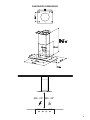 5
5
-
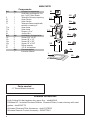 6
6
-
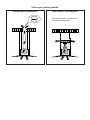 7
7
-
 8
8
-
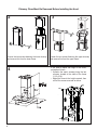 9
9
-
 10
10
-
 11
11
-
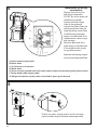 12
12
-
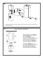 13
13
-
 14
14
-
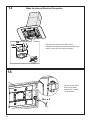 15
15
-
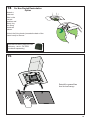 16
16
-
 17
17
-
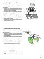 18
18
-
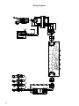 19
19
-
 20
20
-
 21
21
-
 22
22
-
 23
23
-
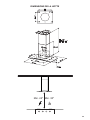 24
24
-
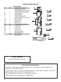 25
25
-
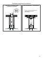 26
26
-
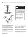 27
27
-
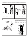 28
28
-
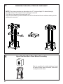 29
29
-
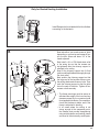 30
30
-
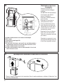 31
31
-
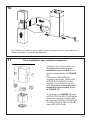 32
32
-
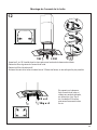 33
33
-
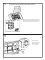 34
34
-
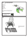 35
35
-
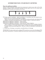 36
36
-
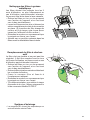 37
37
-
 38
38
-
 39
39
-
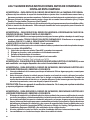 40
40
-
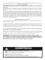 41
41
-
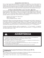 42
42
-
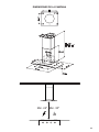 43
43
-
 44
44
-
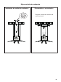 45
45
-
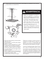 46
46
-
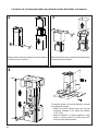 47
47
-
 48
48
-
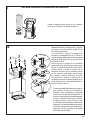 49
49
-
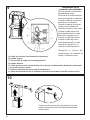 50
50
-
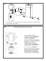 51
51
-
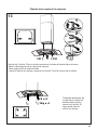 52
52
-
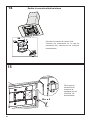 53
53
-
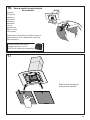 54
54
-
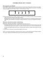 55
55
-
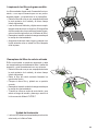 56
56
-
 57
57
-
 58
58
-
 59
59
-
 60
60


Faber Tratto Isola 36 SSV with VAM Guía de instalación
- Categoría
- Campanas de cocina
- Tipo
- Guía de instalación
En otros idiomas
Documentos relacionados
-
Faber GLASIS36SSV Guía de instalación
-
-
-
-
-
-
-
-
-