Faber CYLNIS15SS600 Manual de usuario
- Categoría
- Campanas de cocina
- Tipo
- Manual de usuario
Este manual también es adecuado para

CYLNIS15SS600
Installation Instructions
Use and Care Information
Instructions d'installation
Utilisez et d'entretien
Instrucciones de instalación
Información de uso y cuidado
CYLINDRA ISOLA

2
Contents
Important Safety Instructions 3
Range Hood Dimensions 6
Installation Height Requirements 8
Parts 9
Choose Venting Method 12
Ceiling Hood Preparation 14
Hood Frame Preparation 16
Venting- Non Ducted Recirculation 18
Venting- Ducted Venting 19
Install The Hood Frame 20
Connecting Electricity 21
Install The Hood Body 22
Comfort Panel Installation 25
Operating The Controls 28
Remote Control (Optional) 29
Cleaning Stainless Steel 29
Caring For Filters 30
Replacing Bulbs 31
Warranty 32

3
IMPORTANT SAFETY INSTRUCTIONS
READ AND SAVE THESE INSTRUCTIONS BEFORE YOU START
INSTALLING THIS RANGE HOOD
WARNING: - TO REDUCE THE RISK OF A RANGE TOP GREASE FIRE:
a) Never leave surface units unattended at high settings. Boilovers cause smoking and
greasy spillovers that may ignite. Heat oils slowly on low or medium setting.
b)AlwaysturnhoodONwhencookingathighheatorwhenambeingfood(i.e.Crepes
Suzette, Cherries Jubilee, Peppercorn Beef Flambé).
c) Clean ventilating fans frequently. Grease should not be allowed to accumulate on fan or
lter.
d) Use proper pan size. Always use cookware appropriate for the size of the surface element.
WARNING: - TO REDUCE THE RISK OF INJURY TO PERSONS IN THE EVENT OF A RANGE
TOP GREASE FIRE, OBSERVE THE FOLLOWING*:
a)SMOTHERFLAMESwithaclose-ttinglid,cookiesheet,ormetaltray,thenturnoffthe
burner.BECAREFULTOPREVENTBURNS.Iftheamesdonotgooutimmediately
EVACUATE AND CALL THE FIRE DEPARTMENT.
b) NEVER PICK UP A FLAMING PAN - You may be burned.
c) DO NOT USE WATER, including wet dishcloths or towels - a violent steam explosion will
result.
d) Use an extinguisher ONLY if:
1. You know you have a Class ABC extinguisher, and you already know how to operate
it.
2. Thereissmallandcontainedintheareawhereitstarted.
3. Theredepartmentisbeingcalled.
4. Youcanghttherewithyourbacktoanexit.
* Based on "Kitchen Firesafety Tips" published by NFPA
WARNING - TO REDUCE THE RISK OF FIRE OR ELECTRIC SHOCK, do not use this fan with
any solid-state speed control device.
WARNING - TO REDUCE THE RISK OF FIRE, ELECTRICAL SHOCK, OR INJURY TO PERSONS,
OBSERVE THE FOLLOWING:
1. Use this unit only in the manner intended by the manufacturer. If you have any questions,
contact the manufacturer.
2. Before servicing or cleaning unit, switch power off at service panel and lock the service
disconnecting means to prevent power from being switched on accidentally. When the
service disconnecting means cannot be locked, securely fasten a prominent warning
device, such as a tag, to the service panel.
CAUTION: For General Ventilating Use Only. Do Not Use To Exhaust Hazardous or Explo-
sive Materials and Vapors.
WARNING - TO REDUCE THE RISK OF FIRE, ELECTRICAL SHOCK, OR INJURY TO PERSONS,
OBSERVE THE FOLLOWING:
1. InstallationWorkAndElectricalWiringMustBeDoneByQualiedPerson(s)InAccor-
dance With All Applicable Codes And Standards, Including Fire-Rated Construction.
2. Sufcientairisneededforpropercombustionandexhaustingofgasesthroughthe
ue(chimney)offuelburningequipmenttopreventbackdrafting.Followtheheating
equipment manufacturer's guideline and safety standards such as those published by
the National Fire Protection Association (NFPA), and the American Society for Heating,
Refrigeration and Air Conditioning Engineers (ASHRAE), and the local code authorities.

4
ALL WALL AND FLOOR OPENINGS WHERE THE RANGE HOOD IS INSTALLED
MUST BE SEALED.
This range hood requires at least 24" of clearance between the bottom of the range hood
and the cooking surface or countertop. This hood has been approved by UL at this distance
from the cooktop.
This minimum clearance may be higher depending on local building codes. For gas cooktops
and combination ranges, a minimum of 30" is recommended and may be required.
Overhead cabinets on both sides of this unit must be a minimum of 18" above the cooking
surface or countertop. Consult the cooktop or range installation instructions given by the
manufacturer before making any cutouts.
MOBILE HOME INSTALLATION The installation of this range hood must conform to the
Manufactured Home Construction and Safety Standards, Title 24 CFR, Part 3280 (formerly
Federal Standard for Mobile Home Construction and Safety, Title 24, HUD, Part 280). See
Electrical Requirements"
• Venting system MUST terminate outside the home.
• DO NOT terminate the ductwork in an attic or other enclosed space.
• DO NOT use 4" laundry-type wall caps.
• Flexible-type ductwork is not recommended.
• DO NOT obstruct the ow of combustion and ventilation air.
• Failure to follow venting requirements may result in a re.
WARNING
!
VENTING REQUIREMENTS
Determine which venting method is best for your application. Ductwork can extend either
through the wall or the roof.
The length of the ductwork and the number of elbows should be kept to a minimum to
provide efcient performance. The size of the ductwork should be uniform. Do not install
two elbows together. Use duct tape to seal all joints in the ductwork system. Use caulking
to seal exterior wall or oor opening around the cap.
Flexible ductwork is not recommended. Flexible ductwork creates back pressure and air
turbulence that greatly reduces performance.
Make sure there is proper clearance within the wall or oor for exhaust duct before making
cutouts. Do not cut a joist or stud unless absolutely necessary. If a joist or stud must be cut,
then a supporting frame must be constructed.
WARNING - To Reduce The Risk Of Fire, Use Only Metal Ductwork.
CAUTION-Toreduceriskofreandtoproperlyexhaustair,besuretoductairoutside
– Do not vent exhaust air into spaces within walls or ceilings or into attics, crawl spaces,
or garages.
Cold Weather installations
An additional back draft damper should be installed to minimize backward cold air ow and a nonme-
tallic thermal break should be installed to minimize conduction of outside temperatures as part of the
vent system. The damper should be on the cold air side of the thermal break. The break should be as
close as possible to where the vent system enters the heated portion of the house.
3. When cutting or drilling into wall or ceiling, do not damage electrical wiring and other
hidden utilities.
4. Ducted fans must always be vented to the outdoors.

5
ELECTRICAL REQUIREMENTS
A 120 volt, 60 Hz AC-only electrical supply is required on a separate 15 amp fused circuit.
A time-delay fuse or circuit breaker is recommended. The fuse must be sized per local
codes in accordance with the electrical rating of this unit as specied on the serial/rating
plate located inside the unit near the eld wiring compartment.
ELECTRICAL INSTALLATION WITH WIRING BOX
THIS UNIT MUST BE CONNECTED WITH COPPER WIRE ONLY. Wire sizes must conform
to the requirements of the National Electrical Code, ANSI/NFPA 70 - latest edition, and all
local codes and ordinances. Wire size and connections must conform with the rating of
the appliance. Copies of the standard listed above may be obtained from:
National Fire Protection Association
Batterymarch Park
Quincy, Massachusetts 02269
This appliance should be connected directly to the fused disconnect (or circuit breaker)
through exible, armored or nonmetallic sheathed copper cable. Allow some slack in
the cable so the appliance can be moved if servicing is ever necessary. A UL Listed,
1/2" conduit connector must be provided at each end of the power supply cable (at
the appliance and at the junction box).
When making the electrical connection, cut a 1 1/4" hole in the wall. A hole cut through
wood must be sanded until smooth. A hole through metal must have a grommet.
• Electrical ground is required on this range hood.
• If cold water pipe is interrupted by plastic, nonmetallic gaskets or other
materials, DO NOT use for grounding.
• DO NOT ground to a gas pipe.
• DO NOT have a fuse in the neutral or grounding circuit. A fuse in the neutral
or grounding circuit could result in electrical shock.
• Check with a qualied electrician if you are in doubt as to whether the range
hood is properly grounded.
• Failure to follow electrical requirements may result in a re.
WARNING
!
State of California Proposition 65 Warning (US only)
WARNING
This product contains chemicals known to the State of California to cause cancer
and birth defects or other reproductive harm.
For more information go to www.P65Warnings.ca.gov

6
RANGE HOOD DIMENSIONS
upper
chimney
cover
lower
chimney
cover
- ” min
17
1/2” max
30
5/16”
36”
DUCTED
x
min & max ceiling heights
min
7'
6 5/16"
max
8'
11 13/16"
upper
chimney
cover
lower
chimney
cover
3 15/16” min
17
1/2” max
30
5/16”
36”
x
x = 24" - 30"
min
7'
10 1/4"
max
8'
11 13/16"
ducted
ductless
DUCTLESS
X = Min. 24"
X = Min. 30''
x = 24" - 30"
PERSONAL INJURY HAZARD
Because of the weight and size of the range hood canopy, two or
more people are needed to move and safely install the range hood
canopy.
Failure to properly lift range hood could result in damage to the
product or personal injury.
WARNING
!
cabinet basecabinet base cabinet basecabinet base
24" -30" is the recommende
distance between the
cooktop and range hood
It is recommended that
this hood not be used with
professional gas cooking
24" -30" is the recommende
distance between the
cooktop and range hood
It is recommended that
this hood not be used with
professional gas cooking

7
14 9/16”
5 1/8”
SSELTCUD ”61/31 74 - ”4/1 43
DETCUD ”61/31 74 - ”61/5 03
”61/5 03
”61/7 71
”61/31
5 7/8”
7 7/8”
1/2”
3 5/16”

8
INSTALLATION HEIGHT REQUIREMENTS
MIN. 24" OVER ELECTRIC/
MIN. 30" OVER GAS
Min.24” Min.30”
PREPARING TO ATTACH THE CHIMNEY
The range hood attaches to the ceiling by a metal support structure (B on page
9). This support must be attached to the ceiling before the hood is attached.
This structure must be firmly attached to the ceiling.
FOR WOOD CEILINGS: Use four 4" long wood screws and washers.
FOR PLASTER OR SHEET ROCK CEILINGS:
If possible, the support must be attached to the ceiling joists. If not, a
supporting structure behind the sheet rock must be built.
An access point to the hood from the ceiling or soft must be made for
installation and future access to the range hood.

9
PARTS
REF. PART QTY
A
Hood body 1
B
Telescopic frame complete with extractor 1
C
Mounting template
1
D
Ductless Air Outlet Connector
1
E
Flange ø 4 3/4"
1
F
Reducer Flange ø 5 7/8" - 4 3/4"
1
G
Damper 1
REF
PART
QTY
H
Pozi Screws (1/8" x 1/4")
4
I
Torx Screws (1/4" x 9/16")
4
L
Torx Screws (1/4" x 2 3/4")
4
M
Nuts 4
N
Washers 4
O
Torx Screws (1/4" x 3 1/8")
4
PARTS INCLUDED

10
B
A
D
E
F
A
C
G

11
PARTS NEEDED
PARTS (cont.)
PART
Pipe Clamps
4 3/4" Pipe - NON-DUCTED RECIRCULATION
5 7/8" Pipe - DUCTED VENTING
Wire connectors.
Drywall plugs or other suitable wall fasteners based
on your installation.
TOOLS NEEDED
ACCESSORIES AVAILABLE
ACCESSORY
SKU#
Replacement Activated Charcoal Filter
#FILTER2
Wireless Remote Control
#REMCTRL2
CFM Reducer Kit CFMRED2
TOOL
Tape Measure
Pencil
Electric Drill with 5/16" Drill Bit
Phillips Screwdriver
Torx Screwdriver
Pozi Screwdriver
Flat Head Screwdriver
Metal sheers
Work gloves
Foil tape

12
CHOOSE VENTING METHOD
CHOOSE VENTING METHOD
A) Ducted Venting Installation
B) Non-Ducted Recirculation
1
Requires purchase of
Activated Charcoal
Accessory.
ø 120 mm - ø 150 mm
ø 120 mm
2x
2x
WW
Min.
550 mm
ø 120 mm - ø 150 mm
ø 120 mm
2x
2x
WW
Min.
550 mm

13
DUCTED VENTING INSTALLATION ONLY:
Install
G
Round Damper.
• Disconnect and move freestanding range from counter to
provide easier access to ceiling. Put a thick, protective covering
over cooktop, set-in range or countertop to protect from
damage or dirt.
• Use a plumb line to mark the center of the Stove on the ceiling/
soffit.
2
G

14
3
CEILING HOOD PREPARATION
Ø 10 mm
x4
1 1/4"
C
• Use the mounting template on the ceiling to determine
placement of mounting screws on the ceiling.
• Mark the center of the holes in the ceiling template.
DUE TO THE SIZE AND
WEIGHT OF THIS RANGE
HOOD, THE SUPPORT MUST
BE FIRMLY ATTACHED TO
THE CEILING. For plaster or
sheet rock ceiling, the support
must be attached to the joists.
If this is not possible, a support
structure must be built behind
the plaster or sheet rock.
The manufacturer assumes
no responsibility for injury or
damage caused by improper
installations.
WARNING
!
• Determine and make necessary cuts for the ductwork. The duct opening
is shown on the mounting template. Install ductwork before mounting
the hood.
• Determine the proper location for the Power Supply Cable as indicated
on the template. Use a 1 1/4" Drill Bit to make this hole. Run the Power
Supply Cable. Use caulking to seal around the hole.
• A knockout for threading through the Power Supply from the ceiling is
located on the top of the frame. Do not connect the Power Cable to the
Wiring Box or power up the hood at this time. Run enough power cable
from the ceiling to reach the wiring box.

15
Ø 10 mm
x4
1
2
L
I
OK!
5 mm
N3
N6
N5
OK!
5 mm
OK!
5 mm
D1
• Take either your wood screws
L
or nuts
M
with washer
N
and
screws
O
depending on your set-up and screw into the pilot
holes and leave 1/4" of the heads exposed.
• In this step it's possible to use only 2 screws (as shown).
• For concrete ceilings, use the appropriate plugs for the screw
size (not provided).
4
Torx Screwdriver
L
L
Torx Screws (1/4" x 2 3/4")
O
N
M

16
Remove the lower chimney from the lower frame.
Loosen the two screws fastening the upper chimney and remove this
from the lower frame.
5
6
HOOD FRAME PREPARATION
Phillips Screwdriver

17
If you need to adjust the height of the frame, proceed as follows:
• Unfasten the screws joining the two columns, located at the sides
of the frame.
• Adjust the frame to the height required, then replace all the
screws removed above, and then tighten.
7
Phillips Screwdriver
Flat Head Screwdriver

18
8a
VENTING - NON DUCTED RECIRCULATION
3
5
4
6
Min. 550 mm
900 mm
MIN 770 mm
MAX 1215 mm
MIN 870 mm
MAX 1215 mm
MIN
770
mm
MAX
1215
mm
MIN
870
mm
MAX
1215
mm
N1
N
O2
3
5
4
6
Min. 550 mm
900 mm
MIN 770 mm
MAX 1215 mm
MIN 870 mm
MAX 1215 mm
MIN
770
mm
MAX
1215
mm
MIN
870
mm
MAX
1215
mm
N1
N
O2
INSTALL DUCTLESS DIVERTER
• Attach the Ductless Air Outlet Connector
D
to the upper
frame with 4 screws
H
.
• Attach the ange
E
to the lower part of the ductless outlet
piece.
Pozi Screwdriver
D
H
E
H
Pozi Screws (1/8" x 1/4")

19
INSTALL DUCTED VENTING:
• Install the damper
G
and connect the ducting to the hood and
seal all joints.
• Attach the pipe with the clamps (not included).
• Attach the reducer ange
F
to the air outlet.
• Install ducting (purchased seperately) to connect the lower and
upper ange.
• Attach the pipe with the clamps (not included).
F
G
8b
VENTING - DUCTED VENTING

20
INSTALL THE HOOD FRAME
• Lift the frame to the ceiling, fit the frame slots onto the two screws
inserted in the ceiling.
• Turn the frame to reach the center of the key hole .
9
• Tighten the screws and then attach two more screws
L
or nuts
M
with washer
N
and screws
O
depending on your set-up into the
other holes making sure the screws are seated in the key holes.
Torx Screwdriver
7
9
8
ø 120
ø 150ø 120
1
2
3
O
O1 O1 O1
L
1
2
3
L
Torx Screws (1/4" x 2 3/4")

21
• Before moving onto the next steps, make sure the hood is properly
secured to the ceiling.
• The frame mountings must be secure to withstand the weight of the
hood and any stresses caused by the occasional side thrust applied
to the device. On completion, check that the base is stable, and will
remain stable even if side to side pressure is placed on the hood.
• In all cases where the ceiling is not strong enough at the suspension
point, the installer must provide strengthening using suitable plates
and backing pieces anchored to the structurally sound parts.
1. Remove the cover from the Field Wiring
Compartment with a phillips screwdriver.
Hood
wiring
the range hood (B) with
a twist-on type wire
connector (C).
6. Connect the Green (E)
(Green and Yellow)
ground wire under the
Green grounding screw.
7. Replace the eld wiring
compartment cover.
2. Feed the Power Supply Cable through the electrical knockout.
3. Connect the Power Supply Cable to the range hood.
4. Attach the White lead of the power supply (A) to the White
lead of the range hood (D) with a twist-on type wire connector.
5. Attach the Black lead of the power supply to the Black lead of
10
CONNECTING ELECTRICITY

22
INSTALL THE HOOD BODY
• For ductless installations, the venting holes in the upper stainless
chimney need to be positioned up.
• For ducted installations, the venting holes are positioned on the
bottom.
10
12 13
11
10
12 13
11
11
Ductless
Ducted

23
Phillips Screwdriver
• Place the chimney on the frame and attach it to the upper part of
the frame with the same screws removed previously. Make sure
to match the ductless holes with the ductless box exit inside the
frame if using the ductless application.
14
15
2
1
H2H
N4
• Remove the grease filters by pushing the handle backwards and
put the chimney from the bottom.

24
2
1
N4
• Use 4 screws
I
to attach the chimney to the frame on the bottom,
do not tighten screws
• Attach the chimney to the frame by inserting the screws
I
into
the matching key holes and turn left and tighten screws.
Torx Screwdriver
I
I
Torx Screws (1/4" x 9/16")

25
COMFORT PANEL INSTALLATION
INSTALL THE COMFORT PANEL
1. Install the comfort panel to the bottom of the hood.
2. Slide the xing pin to install the hinge into place and lock the
panel into place by pushing the panel up into the slot.
12

26
Attention:
• Turn the power supply on.
• Turn on blower and lights.
• If the range hood does not operate, check that the circuit breaker
is not tripped or the house fuse blown.
• If the unit still does not operate, disconnect the power supply and
check that the wiring connections have been made properly.
ATTACH THE CONNECTOR
1. Next connect the control and
lighting wires inside the hood
above the grease lters.
13

27
ONLY FOR NON-DUCTED RECIRCULATION OPTION
Required Activated
Charcoal Filter Accessory -
sku # - FILTER2 (purchased
separately)
Attach a charcoal filter in the
correct position and block it
by the Filter hooks as shown.
Unlock the fixing hooks
(towards the back of the
insert hood) to remove.
14
15
Replace the the grease lter.
W
Z

28
OPERATING THE CONTROLS
FOR BEST RESULTS
Start the range hood several minutes before cooking to develop proper
airflow. Allow the range hood to operate for several minutes after cooking
is complete to clear all smoke and odors from the kitchen.
Button Function Led
Turns the lights on/off at maximum strength.
-
Press and hold the button for approximately 2 seconds to turn the
Dimmer Lights On/Off.
-
Turns the motor on/off at speed one.
ON
Turns the Motor on at speed two.
ON
Activated Charcoal Filter Alarm -
Press and hold the button for approximately 5 seconds, with all the
hood turned off (Motor and Lights), to turn the alarm on. The relevant
LED ashes twice to conrm.
To turn the alarm off, press the button again and hold for at least 5
seconds. The relevant LED ashes once.
Turns the Motor on at speed three.
ON
Grease Filter Alarm and Charcoal Filter Alarm
To reset the alarm: press and hold the button for approximately 3
seconds, with the hood turned off (Motor and Lights), and until the LED
S1 ashes three times.
Turns the Motor on at INTENSIVE Speed.
This speed is timed to run for 6 minutes. At the end of this time, the
system returns automatically to the speed that was set before. If it is
activated with the motor turned off, the hood will switch to OFF at the
end of the time.
ON
S1
Signals the Metal Grease Filter saturation alarm, indicating that it is
necessary to wash the lters. The alarm is triggered after the Hood has
been in operation for 100 working hours.
ON
When this is activated, it signals:
The Activated Charcoal Filter saturation alarm, indicating that the lter
must be changed;
The Metal Grease Filters must also be washed. The Activated Charcoal
Filter saturation alarm comes into operation after the Hood has been
working for 200 hours.
Flashing.

29
REMOTE CONTROL (OPTIONAL)
Installing the Battery
• The remote control is powered by a CR2032 type 3 V battery (not included).
• Remove the screw and install the battery.
• Check that the battery is installed with the " + " side up.
Caution:
• Do not place the remote
control near heat sources.
• Do not discard the batteries
with normal waste, they
must be put into the specic
containers.
• Tighten the battery cover
screw tight.
Cleaning Exterior surfaces:
Please note, abrasives and
scouring agents can scratch
range hood nishes and should
not be used to clean nished
surfaces.
CLEANING STAINLESS STEEL
StainlessSteelnishcleaninginstructions:
Clean exterior surfaces with a commercially
available stainless steel cleaner.

30
CARING FOR FILTERS
CLEANING METAL GREASE FILTERS
These can be washed in the dishwasher, and need to be cleaned whenever the
S1 Led comes on or at least once every 2 months of use, or more frequently
if use is particularly intensive.
Resetting the Grease Filter Alarm
1. Turn the Lights and the Hood off.
2. Press
and hold for at least 3 seconds, until LED flashes three
times in confirmation.
Cleaning the Filters
1. Open the Panel.
2. Remove the Filters one at a time, pushing them towards the back of
the unit and at the same time pulling downward.
3. Wash the Filters without bending them, and leave them to dry
completely before replacing. (If the surface of the filter changes color
as time goes by, this will have absolutely no effect on the efficiency
of the filter itself.)
4. Replace the grease filters, taking care to ensure that the handle faces
forward.
5. Completely dry the filters before reinstalling. Otherwise left over
grease may heat and drip.
6. Close the Panel.
Z

31
REPLACING BULBS
LED lights must be replaced by Faber factory authorized
service.
REPLACING ACTIVATED CHARCOAL FILTER
They cannot be washed or regenerated, and must be changed when led S1
starts to ash, or at least once every 4 months. The Alarm signal, if it has been
activated, only appears when the Hood Blower is turned on.
Resetting the Charcoal Filter Alarm
1. Turn the Lights and the Hood off.
2. Press
and hold for at least 3 seconds, until LED flashes three
times in confirmation.
Cleaning the Filters
1. Open the Panel.
2. Remove the Filters one at a time, pushing them towards the back of
the unit and at the same time pulling downward.
3. Remove the saturated charcoal filter by releasing the fixing hooks.
4. Fit the new filter and fasten it in its correct position.
5. Replace, taking care to ensure that the handle faces forwards.
6. "When used in recirculation mode, to Reduce the Risk of Fire and
Shock use only conversion kit Model FILTER 2".
7. Close the Panel.
W

32
WARRANTY
January 4, 2016
FABER CONSUMER WARRANTY & SERVICE
All Faber products are warranted against any defect in materials or workmanship for the original purchaser
for a period of 1 year from the date of original purchase (requires proof of purchase). This warranty covers
labor and replacement parts. Faber, at its option, may repair or replace the product or components
necessary to restore the product to good working condition. To obtain warranty service, contact the dealer
from whom you purchased the range hood, or the local Faber distributor. If you cannot identify a local Faber
distributor, contact us at (508) 358-5353 for the name of a distributor in your area.
The following is not covered by Faber's warranty:
1. Service calls to correct the installation of your range hood, to instruct you how to use your range hood, to
replace or repair house fuses or to correct house wiring or plumbing.
2. Service calls to repair or replace range hood light bulbs, fuses or filters. Those consumable parts are
excluded from warranty coverage.
3. Repairs when your range hood is used for other than normal, single-family household use.
4. Damage resulting from accident, alteration, misuse, abuse, fire, flood, acts of God, improper installation,
installation not in accordance with electrical or plumbing codes or Faber documentation, or use of products
not approved by Faber.
5. Replacement parts or repair labor costs for units operated outside the United States or Canada, including
any non-UL or C-UL approved Faber range hoods.
6. Repairs to the hood resulting from unauthorized modifications made to the range hood.
7. Expenses for travel and transportation for product service in remote locations and pickup and delivery
charges. Faber range hoods should be serviced in the home.
THIS WARRANTY DOES NOT ALLOW RECOVERY OF INCIDENTAL OR CONSEQUENTIAL DAMAGES, INCLUDING, WITHOUT
LIMITATION, DIRECT, INDIRECT, INCIDENTAL, SPECIAL OR CONSEQUENTIAL DAMAGES, PERSONAL INJURY/WRONGFUL
DEATH OR LOST PROFITS FABER WARRANTY IS LIMITED TO THE ABOVE CONDITIONS AND TO THE WARRANTY PERIOD
SPECIFIED HEREIN AND IS EXCLUSIVE. EXCEPT AS EXPRESSLY SPECIFIED IN THIS AGREEMENT, FABER DISCLAIMS ALL
EXPRESS OR IMPLIED CONDITIONS, REPRESENTATIONS, AND WARRANTIES INCLUDING, WITHOUT LIMITATION, ANY
IMPLIED WARRANTIES OF MERCHANTABILITY OR FITNESS FOR A PARTICULAR PURPOSE
.
This warranty gives you specific legal rights that may vary from state to state.
Model#: ______________________________ Serial #: _____________________________

33
TABLE DES MATIÈRES
Importantes consignes de sécurité 34
Dimensions de la hotte 38
Hauteur requise pour l’installation 40
Pièces 41
Outils requis 43
Choisir la méthode de ventilation 44
Préparation de la hotte de plafond 46
Préparation du châssis de la hotte 48
Ventilation - avec recyclage sans canalisation 50
Ventilation - ventilation avec canalisation 51
Installation du châssis de la hotte
52
Branchement électrique
53
Installation du bâti de la hotte
54
Installation du panneau
57
Utilisation des commandes
60
Télécommande (en option)
61
Nettoyage de l’acier inoxydable
61
Entretiendesltres
62
Remplacement des ampoules
63
Garantie
64

34
IMPORTANTES CONSIGNES DE SÉCURITÉ
VEUILLEZ LIRE ET CONSERVER LA PRÉSENTE NOTICE AVANT DE
COMMENCER L'INSTALLATION DE LA HOTTE DE CUISINE
AVERTISSEMENT: - POUR RÉDUIRE LE RISQUE D'UN FEU DE GRAISSE SUR LA TABLE
DE CUISSON:
a) Ne laissez jamais sans surveillance les éléments de la surface de cuisson à température
élevée. Les bouillonnements excessifs peuvent provoquer de la fumée et les débordements
degraissepeuvents'enammer.L'huiledoitêtrechaufféelentement,àunetempérature
basse ou moyenne.
b) Assurez-vous de toujours mettre en marche la hotte lorsque vous cuisinez à température
élevéeoupréparezunmetsambé(p.ex.crêpesSuzette,cerisesjubilé,bœufambé).
c) Nettoyez régulièrement les ventilateurs d'aspiration. Assurez-vous de ne pas laisser de
lagraisses'accumulersurleventilateurouleltre.
d)Utiliseztoujoursdespoêlesetcasserolesdelatailleappropriée.Utiliseztoujoursdes
ustensiles de cuisine de la taille adaptée à celle de l'élément chauffant.
AVERTISSEMENT: - POUR PRÉVENIR LES BLESSURES EN CAS DE FEU DE GRAISSE SUR
LA TABLE DE CUISSON, SUIVEZ LES RECOMMANDATIONS SUIVANTES*:
a) ÉTOUFFEZ LES FLAMMES à l'aide d'un couvercle hermétique, d'une plaque à biscuits ou
d'un plateau métallique, puis éteignez le brûleur. FAITES ATTENTION AUX BRÛLURES.
Si le feu ne s'éteint pas immédiatement, QUITTEZ LES LIEUX ET APPELEZ LES POMPIERS.
b) NE PRENEZ JAMAIS UNE CASSEROLE EN FLAMME - Vous pourriez vous brûler.
c) N'UTILISEZ JAMAIS DE L'EAU, ni un linge à vaisselle ou un torchon mouillé, pour éteindre
le feu. Cela pourrait provoquer une violente explosion de vapeur.
d) Utilisez un extincteur UNIQUEMENT si:
1. Vousêtescertainqu'ils'agitd'unextincteurdeclasseABCetquevousconnaissez
bien son mode d'emploi.
2. Le feu est de faible intensité et se limite à l'endroit où il a démarré.
3. Les pompiers ont déjà été appelés.
4. Unevoiedesortiesetrouvederrièrevouspendantquevouséteignezlesammes.
*
D'après le guide «Kitchen Firesafety Tips» publié par la NFPA aux États-Unis
AVERTISSEMENT - POUR RÉDUIRE LE RISQUE D'INCENDIE OU DE CHOC ÉLECTRIQUE,
n'utilisez jamais ce ventilateur en association avec un dispositif de réglage de vitesse à
semi-conducteurs.
AVERTISSEMENT - POUR RÉDUIRE LES RISQUES D'INCENDIE, DE CHOC ÉLECTRIQUE OU
DE BLESSURE CORPORELLE, RESPECTEZ LES INSTRUCTIONS SUIVANTES:
1. Utilisez cet appareil uniquement de la façon prévue par le fabricant. Pour toute question,
communiquez avec le fabricant.
2. Avant de procéder à l'entretien ou au nettoyage de l'appareil, coupez l'alimentation au
niveau du panneau électrique et verrouillez-le pour vous assurer que l'électricité n'est pas
rétablie accidentellement. S'il n'est pas possible de verrouiller le dispositif d'interruption
del'alimentation,afchezdefaçonfermeetbienvisibleunavisdedanger,parexemple
à l'aide d'une étiquette sur le panneau.
ATTENTION:Destinéàunusagedeventilationgénéraleuniquement.N'utilisezpasce
dispositif pour l'aspiration de vapeurs ou de matériaux dangereux ou explosifs.
AVERTISSEMENT - POUR RÉDUIRE LES RISQUES D'INCENDIE, DE CHOC ÉLECTRIQUE OU
DEBLESSURECORPORELLE,RESPECTEZLESINSTRUCTIONSSUIVANTES:
1. L'installationetlebranchementélectriquedoiventêtreréalisésparuntechnicienqualié

35
TOUTE OUVERTURE DANS LE MUR OU LE PLANCHER À PROXIMITÉ DE LA HOTTE
DOIT ÊTRE SCELLÉE.
Un espace libre d'au moins 24" est requis entre le bas de la hotte et la surface de cuisson ou
le comptoir. Cette hotte a été homologuée par l'UL à cette distance de la surface de cuisson.
L’espace libre minimal requis peut-être plus grand, selon la réglementation en matière de
construction de votre région. Pour les cuisinières à gaz et les cuisinières combinées, un espace
minimal de 30" est recommandé et pourrait être exigé.
Les armoires suspendues de chaque côté de l'appareil doivent se trouver à au moins 18" de la
surface de cuisson ou du comptoir. Consultez la notice d'installation de la surface de cuisson
ou de la cuisinière fournie par le fabricant avant de pratiquer des ouvertures.
INSTALLATION DANS UNE MAISON MOBILE L'installation de cette hotte doit être conforme
à la Partie 3280 de la norme Manufactured Home Construction and Safety Standards, Title 24
CFR (précédemment la partie 280 de la norme Federal Standard for Mobile Home Construction
and Safety, Title 24, HUD). Consultez la che technique électrique"
CRITÈRES DE VENTILATION
Déterminez quelle méthode de ventilation est mieux adaptée à votre application. Les conduits
peuvent passer par le mur ou le toit.
Pour garantir une meilleure efcacité, la longueur des conduits et le nombre de coudes doivent
être le plus limités que possible. Le diamètre des conduits devrait être uniforme. N'installez pas
deux coudes ensemble. Utilisez un ruban pour canalisations an de sceller tous les joints du
système de conduits. Utilisez un calfeutrage pour sceller les ouvertures dans le mur extérieur
ou le plancher, autour du clapet.
Iln'estpasrecommandéd'utiliserdesconduitsexibles.Lesconduitsexiblesprovoquent
unecontre-pressionetdelaturbulencequidiminuentgrandementl'efcacitédel'appareil.
Assurez-vous que l'espace libre dans le mur ou le plancher est sufsant pour le conduit
d'évacuation avant de pratiquer les ouvertures. Ne coupez jamais une poutre ou un chevron,
sauf si c'est absolument nécessaire. S'il s'avère nécessaire de couper une poutre ou un chevron,
la construction d'un renforcement est requise.
AVERTISSEMENT - Pour réduire le risque d'incendie, utilisez uniquement des conduits
métalliques.
ATTENTION - Pour réduire le risque d'incendie et pour évacuer adéquatement l'air, assurez-
vous de raccorder les conduits à l'extérieur – Ne diffusez pas l'air d'évacuation dans des
espaces à l'intérieur des murs ou du plafond, ou encore à l'intérieur d'un grenier, d'une
galerie technique ou d'un garage.
1. et conformément à tous les codes et normes en vigueur, incluant ceux concernant la
construction à l'épreuve du feu.
2. Andegarantirunecombustionetuneévacuationadéquatesdesgazparlesconduites
de la cheminée des appareils à combustion, une bonne aération est nécessaire pour
éviter le refoulement. Respectez les lignes directrices fournies par le fabricant du matériel
chauffant, ainsi que les normes de sécurité comme celles publiées par la National Fire
Protection Association (NFPA) et la American Society for Heating, Refrigeration and
Air Conditioning Engineers (ASHRAE) aux États-Unis, ainsi que les codes en vigueur
dans votre région.
3. Lorsque vous faites une ouverture ou percez dans un mur ou le plafond, veillez à ne
pasendommagerleslsélectriquesoud'autresdispositifscachés.
4. Lesventilateurscanalisésdoiventtoujoursêtreraccordésàl'extérieur.

36
FICHE TECHNIQUE ÉLECTRIQUE
Une alimentation de courant alternatif de 120 volts à 60 Hz est requise sur un circuit à fusible
distinct de 15 ampères. Il est recommandé d'installer un fusible temporisé ou un disjoncteur.
Le fusible doit être calibré conformément aux codes en vigueur pour les caractéristiques
nominales électriques de l'appareil, indiquées sur la plaque signalétique située à l'intérieur
de l'appareil, à proximité du compartiment des câblages externes.
INSTALLATION ÉLECTRIQUE AVEC BOÎTIER DE CONNEXION
CET APPAREIL DOIT ÊTRE UNIQUEMENT BRANCHÉ À L'AIDE DE FILS DE CUIVRE. Le
calibre des ls doit être conforme aux critères de la dernière édition du National Electrical
Code, de l'ANSI/NFPA 70 et de l'ensemble des codes et réglementations en vigueur. Le
calibre des ls et les connexions doivent être adaptés aux caractéristiques nominales de
l'appareil. Il est possible de se procurer un exemplaire des normes indiquées ci-dessus en
communiquant avec:
National Fire Protection Association
Batterymarch Park
Quincy, Massachusetts 02269 (États-Unis)
Cet appareil devrait être branché directement au sectionneur à fusible (ou au disjoncteur)
par un câble exible de cuivre avec blindage ou gaine non métallique. Laissez un
peu de jeu dans le câble pour permettre le déplacement de l'appareil si des travaux
d'entretien s'avéraient nécessaires. Un raccord de conduit homologué par l'UL de 1/2"
doit être installé aux deux extrémités du câble d'alimentation (au niveau de l'appareil
et de la boîte de liaison).
Lors de la réalisation du branchement électrique, réalisez un trou de 1 1/4" dans le mur.
S'il s'agit d'un trou dans le bois, il doit être poncé pour le rendre lisse. S'il s'agit d'un
trou dans le métal, un passe-ls est requis.
• Le système de ventilation DOIT déboucher à l'extérieur.
• NE FAITES PAS déboucher les conduits dans un grenier ou un autre endroit
fermé.
• N’UTILISEZ PAS un clapet de sécheuse mural de 4".
• Il n'est pas recommandé d'utiliser des conduits exibles.
• N’ENTRAVEZ PAS le ux de l'air de combustion et de ventilation.
• Le non-respect des exigences en matière de ventilation pourrait entraîner un
incendie.
AVERTISSEMENT
!
Installation dans les climats froids
Le système de ventilation doit prévoir un registre antirefoulement supplémentaire pour réduire le
ux d'air froid inverse, ainsi qu'une barrière thermique non métallique pour réduire la conduction des
températures extérieures. Le registre doit être installé du côté air froid par rapport à la barrière thermique.
La barrière thermique doit être positionnée le plus près que possible de l'endroit où le système de
ventilation pénètre dans la partie chauffée de la maison.

37
• Une mise à la terre électrique est requise pour cette hotte.
• N'UTILISEZ PAS un tuyau d'eau froide pour la mise à la terre si celui-ci est
branché par des joints en plastique, par des rondelles non métalliques ou
d'autres matériaux.
• N'UTILISEZ PAS une conduite de gaz pour la mise à la terre.
• N'INSTALLEZ PAS un fusible sur le circuit neutre ou le circuit de mise à la
terre. La présence d'un fusible dans le circuit neutre ou de mise à la terre
peut entraîner un choc électrique.
• Consultez un électricien qualié si vous n'êtes pas certain de la mise à la terre
de la hotte.
• Le non-respect des exigences de la che technique électrique pourrait
entraîner un incendie.
AVERTISSEMENT
!
Avertissement relatif à la proposition 65 de l’État de Californie (États-Unis
uniquement)
AVERTISSEMENT
Ce produit contient des éléments chimiques que l’État de Californie considère
comme étant cancérigènes ou causant des malformations congénitales ou d’autres
troubles de la reproduction.
Pour de plus amples renseignements, consultez le site www.P65Warnings.
ca.gov

38
DIMENSIONS DE LA HOTTE
- ” min.
17
1/2” max.
30
5/16”
36”
AVEC CANALISATION
x
hauteur de plafond min. / max.
min.
7'
6 5/16"
max.
8'
11 13/16"
3 15/16” min.
17
1/2” max.
30
5/16”
36”
x
x = 24" - 30"
min.
7'
10 1/4"
max.
8'
11 13/16"
canalisée
sans canalisation
SANS CANALISATION
X = Min. 24"
X = Min. 30''
x = 24" - 30"
habillage de
cheminée
supérieur
habillage de
cheminée
inférieur
habillage de
cheminée
inférieur
habillage de
cheminée
supérieur
RISQUE DE BLESSURE CORPORELLE
Compte tenu du poids et de la dimension du cadre de la hotte, deux
personnes ou plus sont requises pour le transporter et l’installer en
toute sécurité.
Si la hotte n’est pas soulevée de manière adéquate, cela pourrait
entraîner des blessures, ou encore le produit pourrait être
endommagé.
AVERTISSEMENT
!
base de l’armoirebase de l’armoire base de l’armoirebase de l’armoire
La distance recommandée
entre la surface de cuisson
et la hotte est de 24" à 30".
Il n’est pas recommandé
d’utiliser cette hotte en
cas de cuisine de type
professionnel au gaz.
La distance recommandée
entre la surface de cuisson
et la hotte est de 24" à 30".
Il n’est pas recommandé
d’utiliser cette hotte en
cas de cuisine de type
professionnel au gaz.

39
14 9/16”
5 1/8”
SANS CANALISATION ”61/31 74 - ”4/1 43
AVEC CANALISATION” 61/31 74 - ”61/5 03
”61/5 03
”61/7 71
”61/31
5 7/8”
7 7/8”
1/2”
3 5/16”

40
HAUTEUR REQUISE POUR L’INSTALLATION
MIN. 24" AU-DESSUS
D’UNE SURFACE
ÉLECTRIQUE/MIN. 30"
AU-DESSUS D’UNE
SURFACE AU GAZ
Min.24” Min.30”
PRÉPARATION DE L’INSTALLATION DE LA CHEMINÉE
La hotte est fixée au plafond à l’aide d’une structure de soutien métallique (B
à la page9). Ce socle doit être fixé au plafond avant l’installation de la hotte.
Cette structure doit être fermement ancrée au plafond.
POUR LES PLAFONDS EN BOIS: Utilisez 4vis à bois d’une longueur de 4" et
des rondelles.
POUR LES PLAFONDS EN PLÂTRE OU PLAQUE DE PLÂTRE:
Si possible, le socle doit être ancré aux poutres. Autrement, une structure de
soutien doit être construite derrière la plaque de plâtre.
Un point d’accès à la hotte doit être créé dans le plafond ou le parement pour
l’installation et en vue d’accéder plus tard à la hotte.

41
PIÈCES
RÉF. PIÈCE QTÉ
A
Bâti de la hotte 1
B
Châssis télescopique avec ventilateur d’aspiration 1
C
Gabarit de montage
1
D
Raccord de sortie d’air sans canalisation
1
E
Flasque ø 4 3/4"
1
F
Flasque réducteur ø 57/8" - 43/4"
1
G
Registre 1
RÉF. PIÈCE QTÉ
H
Vis à tête Pozidriv (1/8" x 1/4")
4
I
Vis à tête étoile (1/4" x 9/16")
4
L
Vis à tête étoile (1/4" x 23/4")
4
M
Écrous 4
N
Rondelles 4
O
Vis à tête étoile (1/4" x 31/8")
4
PIÈCES INCLUSES

42
B
A
D
E
F
A
C
G

43
PIÈCES REQUISES
PIÈCES (suite)
PIÈCE
Colliers de serrage
Tuyau 43/4" - AVEC RECYCLAGE SANS
CANALISATION
Tuyau 57/8" - AVEC VENTILATION CANALISÉE
Connecteurs de ls.
Chevilles pour cloison sèche ou autre système de
xation mural, en fonction de votre installation.
OUTILS REQUIS
ACCESSOIRES DISPONIBLES
ACCESSOIRE
NO D’ARTICLE
Filtre à charbon actif de rechange
#FILTER2
Télécommande sans l
#REMCTRL2
Réducteur de débit CFMRED2
OUTILS
Ruban à mesurer
Crayon
Perceuse électrique avec mèche de 5/16"
Tournevis cruciforme
Tournevis étoile
Tournevis Pozidriv
Tournevis à lame plate
Cisailles à métaux
Gants de sécurité
Ruban métallique

44
CHOISIR LA MÉTHODE DE VENTILATION
CHOISIR LA MÉTHODE DE VENTILATION
A) Installation avec ventilation canalisée
B) Avec recyclage sans canalisation
1
Exige l'achat de
l'accessoire à charbon
actif.
ø 120 mm - ø 150 mm
ø 120 mm
2x
2x
WW
Min.
550 mm
ø 120 mm - ø 150 mm
ø 120 mm
2x
2x
WW
Min.
550 mm

45
INSTALLATION AVEC VENTILATION CANALISÉE UNIQUEMENT:
Installez
G
le registre circulaire.
• Débranchez la cuisinière et éloignez-la du comptoir pour
faciliter l’accès à plafond. Placez une protection épaisse sur la
surface de cuisson, la cuisinière encastrée ou le comptoir pour
éviter qu'ils soient endommagés ou salis.
• Utilisez un fil à plomb pour marquer le centre de la cuisinière au
plafond/parement.
2
G

46
3
PRÉPARATION DE LA HOTTE DE PLAFOND
Ø 10 mm
x4
11/4"
C
• Utilisez le gabarit de montage au plafond pour déterminer la
position des vis de montage sur le plafond.
• Tracez des repères au centre des trous indiqués sur le gabarit
de montage au plafond.
COMPTE TENU DE LA DIMENSION ET DU
POIDS DE CETTE HOTTE, LE SOCLE DOIT
ÊTRE SOLIDEMENT ANCRÉ AU PLAFOND.
Si le plafond est en plâtre ou en plaque de
plâtre, le socle doit être ancré aux poutres.
Si cela n'est pas possible, une structure de
soutien doit être construite derrière le plâtre
ou la plaque de plâtre. Le fabricant ne peut
être tenu responsable en cas de blessures ou
de dommages provoqués par une mauvaise
installation.
AVERTISSEMENT
!
• Déterminez les ouvertures nécessaires pour les conduits et pratiquez-
les. L'ouverture pour la canalisation est représentée sur le gabarit de
montage. Installez les conduits avant de monter la hotte.
• Déterminez l'emplacement adéquat pour le câble d'alimentation, comme
indiqué sur le gabarit. Utilisez une mèche de 11/4" pour percer ce trou.
Faites passer le câble d'alimentation. Utilisez un calfeutrage pour sceller
autour du trou.
• Une pièce à défoncer pour le passage de l'alimentation électrique du
plafond est située au sommet du châssis. Ne branchez pas le câble
d'alimentation au boîtier de connexion et n'alimentez pas la hotte à
ce moment. Acheminez une longueur de câble électrique du plafond
suffisante pour atteindre le boîtier de connexion.

47
Ø 10 mm
x4
1
2
L
I
OK!
5 mm
N3
N6
N5
OK!
5 mm
OK!
5 mm
D1
• Prenez ensuite les vis à bois
L
ou encore les écrous
M
avec
rondelles
N
et vis
O
, selon votre installation, et installez-les
dans les trous d'implantation, en laissant libre 1/4" de la tête des
vis.
• Pour cette étape, il est possible d’utiliser uniquement 2vis
(comme illustré).
• Pour les plafonds en béton, utilisez les chevilles appropriées en
fonction de la dimension des vis (non fournies).
4
Tournevis étoile
L
L
Vis à tête étoile (1/4" x 23/4")
O
N
M

48
Enlevez la section inférieure de la cheminée du châssis inférieur.
Desserrez les deux vis qui fixent la section inférieure de la cheminée
et détachez-la du châssis inférieur.
5
6
PRÉPARATION DU CHÂSSIS DE LA HOTTE
Tournevis cruciforme

49
Si vous devez régler la hauteur du châssis, procédez comme suit:
• Détachez les vis qui unissent les deux colonnes, situées sur les
côtés du châssis.
• Réglez le châssis à la hauteur requise, puis replacez toutes les vis
enlevées à l’étape précédente; serrez-les.
7
Tournevis cruciforme
Tournevis à lame plate

50
8a
VENTILATION - AVEC RECYCLAGE SANS
CANALISATION
3
5
4
6
Min. 550 mm
900 mm
MIN 770 mm
MAX 1215 mm
MIN 870 mm
MAX 1215 mm
MIN
770
mm
MAX
1215
mm
MIN
870
mm
MAX
1215
mm
N1
N
O2
3
5
4
6
Min. 550 mm
900 mm
MIN 770 mm
MAX 1215 mm
MIN 870 mm
MAX 1215 mm
MIN
770
mm
MAX
1215
mm
MIN
870
mm
MAX
1215
mm
N1
N
O2
INSTALLATION DU DÉFLECTEUR DE RECYCLAGE
• Fixez le raccord de sortie d’air sans canalisation
D
à la section
supérieure du châssis à l’aide de 4vis
H
.
• Posez le asque
E
sur la partie inférieure de la pièce de sortie
sans canalisation.
Tournevis Pozidriv
D
H
E
H
Vis à tête Pozidriv (1/8" x 1/4")

51
INSTALLATION DE LA VENTILATION AVEC CANALISATION:
• Installez le registre
G
et raccordez la canalisation à la hotte,
puis scellez tous les joints.
• Fixez le tuyau à l’aide des colliers (non inclus).
• Posez le asque réducteur
F
sur la sortie de l’air.
• Installez les canalisations (achetées séparément) pour raccorder
le asque du haut et le asque du bas.
• Fixez le tuyau à l’aide des colliers (non inclus).
F
G
8b
VENTILATION - VENTILATION AVEC CANALISATION

52
INSTALLATION DU CHÂSSIS DE LA HOTTE
• Soulevez le châssis jusqu’au plafond, en insérant les deux vis du
plafond dans les fentes du châssis.
• Tournez le châssis pour atteindre le centre des trous en forme de
poire.
9
• Serrez les vis, puis posez deux autres vis
L
ou écrous
M
avec
rondelles
N
et vis
O
, selon votre type d’installation, dans les
autres trous, en vous assurant que les vis sont bien ancrées dans
les trous en forme de poire.
Tournevis étoile
7
9
8
ø 120
ø 150ø 120
1
2
3
O
O1 O1 O1
L
1
2
3
L
Vis à tête étoile (1/4" x 23/4")

53
• Avant de passer aux étapes suivantes, assurez-vous que la hotte
est adéquatement fixée au plafond.
• Le montage du châssis doit être assez solide pour supporter le poids
de la hotte et tout stress causé par une pression latérale occasionnelle
que pourrait subir l'appareil. Lorsque vous avez terminé, vérifiez si la
base est stable et si elle restera stable même si une pression latérale
est appliquée sur la hotte
• Dans tous les cas où le plafond n'est pas assez fort au point de
suspension, l'installateur doit veiller à le renforcer à l'aide de plaques
et de pièces de renfort ancrées à des pièces structurelles solides.
1. Retirez le couvercle du compartiment des câblages
externes à l’aide d’un tournevis cruciforme.
Câblage
de la
hotte
5. Branchez le l noir de
l'alimentation au l
noir de la hotte (B) à
l'aide d'un connecteur
verrouillé par rotation
(C).
6. Branchez le l vert (E)
(vert et jaune) de mise à
la terre sous la vis verte
de mise à la terre.
7. Remettez en place
le couvercle du
compartiment des
câblages externes.
2. Faites passer le câble d'alimentation dans l'entrée électrique
défoncée.
3. Branchez le câble d'alimentation à la hotte.
4. Branchez le l blanc de l'alimentation (A) au l blanc de la
hotte (D) à l'aide d'un connecteur verrouillé par rotation.
10
BRANCHEMENT ÉLECTRIQUE

54
INSTALLATION DU BÂTI DE LA HOTTE
• Pour les installations sans canalisation , les orifices de ventilation
de la cheminée supérieure en acier inoxydable doivent être
orientés vers le haut.
• Pour les installations avec canalisation , les orifices de ventilation
doivent être orientés vers le bas.
10
12 13
11
10
12 13
11
11
Sans canalisation
Avec canalisation

55
Tournevis cruciforme
• Posez la cheminée sur le châssis et fixez-la à la partie supérieure
du châssis en utilisant les vis enlevées précédemment. Assurez-
vous d’aligner les trous à la sortie du boîtier sans canalisation à
l’intérieur du châssis, si vous utilisez l’application sans canalisation.
14
15
2
1
H2H
N4
• Enlevez les filtres à graisse en poussant sur la poignée vers l’arrière
et en tirant la cheminée vers le bas.

56
2
1
N4
• Utilisez 4vis
I
pour fixer la cheminée au bas du châssis. Ne serrez
pas les vis.
• Fixez la cheminée au châssis en insérant les vis
I
dans les trous
en forme de poire, puis tournez vers la gauche et serrez les vis.
Tournevis étoile
I
I
Vis à tête étoile (1/4" x 9/16")

57
INSTALLATION DU PANNEAU
INSTALLATION DU PANNEAU
1. Installez le panneau au bas de la hotte.
2. Faites glisser la cheville de xation pour bloquer la charnière
en place et verrouillez le panneau en le poussant vers le haut
dans les fentes.
12

58
Ànoter:
• Mettez l'alimentation sous tension.
• Mettez le ventilateur et l'éclairage en marche.
• Si la hotte ne fonctionne pas, assurez-vous que le disjoncteur ou
le fusible du domicile n'a pas sauté.
• Si l'unité ne fonctionne toujours pas, débranchez l'alimentation et
vériez si les branchements ont été réalisés correctement.
BRANCHEMENT DU CONNECTEUR
1. Branchez ensuite les ls de
commande et d’éclairage à
l’intérieur de la hotte, au-dessus
des ltres à graisse.
13

59
POUR OPTION SANS CANALISATION, AVEC RECYCLAGE D’AIR
Filtre à charbon actif
accessoire requis - No
d'article - FILTER2 (acheté
séparément)
Posez un filtre à charbon
à l'emplacement adéquat
et bloquez-le à l'aide des
crochets, comme illustré.
Déverrouillez les crochets de
fixation (vers l'arrière de la
hotte encastrable) pour les
enlever.
14
15
Remettez en place le ltre à graisse
métallique.
W
Z

60
UTILISATION DES COMMANDES
POUR DE MEILLEURS RÉSULTATS
Activez la hotte quelques minutes avant de commencer à cuisiner pour
créer un flux d'air adéquat. Laissez la hotte fonctionner quelques minutes
après avoir fini de cuisiner pour absorber toute la fumée et les odeurs de la
cuisine.
Bouton Fonction DEL
Allume/Éteint l'éclairage à la puissance maximale.
-
Appuyez sur ce bouton et tenez-le enfoncé pendant environ 2secondes
pour allumer/éteindre l’éclairage à intensité variable.
-
Allume et éteint le moteur à la vitesse un.
ACTIVÉ
Allume le moteur à la vitesse deux.
ACTIVÉ
Alarme du ltre à charbon actif -
Appuyez sur ce bouton et tenez-le enfoncé pendant environ
5secondes, lorsque tous les dispositifs sont éteints (moteur et
éclairage), pour activer cette alarme. Le témoin DEL approprié clignote
deux fois pour conrmer.
Pour éteindre l'alarme, appuyez de nouveau sur le bouton et tenez-
le enfoncé pendant au moins 5secondes. Le témoin DEL approprié
clignote une fois.
Allume le moteur à la vitesse trois.
ACTIVÉ
Alarme du ltre à graisse et alarme du ltre à charbon actif
Pour réinitialiser l’alarme: appuyez sur ce bouton et tenez-le enfoncé
pendant environ 3secondes, lorsque tous les dispositifs de la hotte sont
éteints (moteur et éclairage), jusqu’à ce que le témoin DELS1 clignote
trois fois.
Allume le moteur à la vitesse INTENSIVE.
Cette vitesse est programmée pour fonctionner pendant 6minutes.
Après ce délai, le système retournera automatiquement à la vitesse
sélectionnée précédemment. Si cette modalité est activée tandis que le
moteur est éteint, la hotte s'éteindra après le délai.
ACTIVÉ
S1
L'alarme de saturation du ltre à graisse métallique signale qu'il est
nécessaire de nettoyer les ltres. L'alarme s'active lorsque la hotte a été
en fonction pendant 100heures.
ACTIVÉ
Lorsqu’elle est activée:
l’alarme de saturation du ltre à charbon actif signale que le ltre doit
être changé;
les ltres à graisse métalliques doivent également être nettoyés.
L'alarme de saturation du ltre à charbon actif s'active lorsque la hotte a
été en fonction pendant 200heures.
Clignotant.

61
TÉLÉCOMMANDE (EN OPTION)
Installation de la pile
• La télécommande est alimentée par une pile 3 V de type CR2032 (n’est
pas incluse).
• Retirez la vis et installez la pile.
• Assurez-vous que la pile est installée avec le symbole «+» vers le haut.
Attention:
• Ne déposez pas la
télécommande à proximité de
sources de chaleur.
• Ne jetez pas les piles avec
les déchets courants. Elles
doivent être jetées dans des
contenants particuliers.
• Serrez à fond les vis du
compartiment de la pile.
Nettoyage des surfaces
extérieures:
Veuillez noter que l’utilisation
de produits abrasifs ou solvants
peut endommager la supercie
de la hotte; ils ne devraient pas
être utilisés pour le nettoyage
des surfaces.
NETTOYAGE DE L’ACIER INOXYDABLE
Instructions pour le nettoyage de l’acier inoxydable:
Nettoyez les surfaces extérieures avec un agent
nettoyant pour l’acier inoxydable disponible sur le
marché.

62
ENTRETIEN DES FILTRES
NETTOYAGE DES FILTRES À GRAISSE MÉTALLIQUES
Ils peuvent être lavés dans le lave-vaisselle et doivent être nettoyés lorsque
le témoin DEL S1 s'allume ou au moins une fois tous les 2mois d'usage, ou
encore plus fréquemment en cas d'utilisation particulièrement intensive.
Réinitialisationdel’alarmedultreàgraisse
1. Éteignez l'éclairage et la hotte.
2. Appuyez sur
et tenez-le enfoncé pendant au moins 3secondes,
jusqu'à ce que le témoin DEL clignote 3fois pour confirmer.
Nettoyagedesltres
1. Ouvrez le panneau.
2. Retirez les filtres un à un, en les poussant vers l'arrière de l'appareil
et en les tirant vers le bas simultanément.
3. Lavez les filtres sans les plier et laissez-les sécher complètement avant
de les remettre en place. (Si la surface du filtre change de couleur au
fil du temps, cela n'aura aucun impact sur l'efficacité du filtre même.)
4. Remettez les filtres à graisse en place, en vous assurant que leur
poignée se trouve vers l'avant.
5. Faites sécher complètement les filtres avant de les remettre en place.
Autrement, des résidus de graisse pourraient chauffer et couler.
6. Refermez le panneau.
Z

63
REMPLACEMENT DES AMPOULES
LesampoulesDELdoiventêtreremplacéesparun
service d'entretien autorisé Faber.
REMPLACEMENT DU FILTRE À CHARBON ACTIF
Ils ne peuvent être lavés ni régénérés, et doivent être changés lorsque le
témoin DEL S1 commence à clignoter, ou au moins une fois tous les 4mois.
S’il a été activé, le signal d'alarme apparaît uniquement lorsque le ventilateur
de hotte est activé.
Réinitialisationdel’alarmedultreàcharbon
1. Éteignez l'éclairage et la hotte.
2. Appuyez sur
et tenez-le enfoncé pendant au moins 3secondes,
jusqu'à ce que le témoin DEL clignote 3fois pour confirmer.
Nettoyagedesltres
1. Ouvrez le panneau.
2. Retirez les filtres un à un, en les poussant vers l'arrière de l'appareil
et en les tirant vers le bas simultanément.
3. Retirez le filtre à charbon saturé en détachant les crochets de fixation.
4. Posez le nouveau filtre et fixez-le à l'emplacement adéquat.
5. Remettez-le en place, en vous assurant que la poignée se trouve
vers l'avant.
6. "Pour réduire le risque d’incendie ou de choc électrique, lorsque
l’appareil est utilisé en mode recyclage, utilisez uniquement le modèle
FILTER2 en guise de trousse de conversion."
7. Refermez le panneau.
W

64
GARANTIE
January 4, 2016
FABER CONSUMER WARRANTY & SERVICE
All Faber products are warranted against any defect in materials or workmanship for the original purchaser
for a period of 1 year from the date of original purchase (requires proof of purchase). This warranty covers
labor and replacement parts. Faber, at its option, may repair or replace the product or components
necessary to restore the product to good working condition. To obtain warranty service, contact the dealer
from whom you purchased the range hood, or the local Faber distributor. If you cannot identify a local Faber
distributor, contact us at (508) 358-5353 for the name of a distributor in your area.
The following is not covered by Faber's warranty:
1. Service calls to correct the installation of your range hood, to instruct you how to use your range hood, to
replace or repair house fuses or to correct house wiring or plumbing.
2. Service calls to repair or replace range hood light bulbs, fuses or filters. Those consumable parts are
excluded from warranty coverage.
3. Repairs when your range hood is used for other than normal, single-family household use.
4. Damage resulting from accident, alteration, misuse, abuse, fire, flood, acts of God, improper installation,
installation not in accordance with electrical or plumbing codes or Faber documentation, or use of products
not approved by Faber.
5. Replacement parts or repair labor costs for units operated outside the United States or Canada, including
any non-UL or C-UL approved Faber range hoods.
6. Repairs to the hood resulting from unauthorized modifications made to the range hood.
7. Expenses for travel and transportation for product service in remote locations and pickup and delivery
charges. Faber range hoods should be serviced in the home.
THIS WARRANTY DOES NOT ALLOW RECOVERY OF INCIDENTAL OR CONSEQUENTIAL DAMAGES, INCLUDING, WITHOUT
LIMITATION, DIRECT, INDIRECT, INCIDENTAL, SPECIAL OR CONSEQUENTIAL DAMAGES, PERSONAL INJURY/WRONGFUL
DEATH OR LOST PROFITS FABER WARRANTY IS LIMITED TO THE ABOVE CONDITIONS AND TO THE WARRANTY PERIOD
SPECIFIED HEREIN AND IS EXCLUSIVE. EXCEPT AS EXPRESSLY SPECIFIED IN THIS AGREEMENT, FABER DISCLAIMS ALL
EXPRESS OR IMPLIED CONDITIONS, REPRESENTATIONS, AND WARRANTIES INCLUDING, WITHOUT LIMITATION, ANY
IMPLIED WARRANTIES OF MERCHANTABILITY OR FITNESS FOR A PARTICULAR PURPOSE
.
This warranty gives you specific legal rights that may vary from state to state.
Model#: ______________________________ Serial #: _____________________________

65
CONTENIDO
Instrucciones de seguridad importantes 66
Dimensiones de la campana extractora 70
Requisitos de altura de instalación 72
Piezas 73
Herramientas necesarias 75
Elegir el método de ventilación 76
Preparación de la campana de techo 78
Preparación del bastidor de la campana 80
Ventilación - recirculación sin conducto 82
Ventilación - ventilación con conducto 83
Instale el bastidor de la campana
84
Conexión de la electricidad
85
Instale el cuerpo de la campana
86
Instalación del panel de confort
89
Operación de los controles
92
Control remoto (opcional)
93
Limpieza del acero inoxidable
93
Cuidadodelosltros
94
Reemplazo de bombillas
95
Garantía
96

66
INSTRUCCIONES DE SEGURIDAD IMPORTANTES
LEA Y GUARDE ESTAS INSTRUCCIONES ANTES DE COMENZAR A
INSTALAR ESTA CAMPANA EXTRACTORA
ADVERTENCIA: - PARA REDUCIR EL RIESGO DE INCENDIO DE LA CAMPANA POR GRASA:
a)Nuncadejelasunidadesdesuperciedesatendidasenajustesaltos.Losderramespor
ebullición pueden causar humos y derrames de grasa que pueden incendiarse. Caliente
los aceites lentamente en ajustes bajos o medios.
b)Siempreenciendalacampanacuandococineafuegoaltoocuandoameealimentos
(por ej. Crepes Suzette, Cherries Jubilee, Peppercorn Beef Flambé).
c) Limpie los ventiladores con frecuencia. No se debe permitir que la grasa se acumule en
elventiladoroenelltro.
d) Use una olla de tamaño adecuado. Utilice siempre utensilios de cocina apropiados para
eltamañodelelementodesupercie.
ADVERTENCIA: - PARA REDUCIR EL RIESGO DE LESIONES A PERSONAS EN CASO DE
INCENDIO DE GRASA EN LA CAMPANA, TENGA EN CUENTA LO SIGUIENTE*:
a) APAGUE LAS LLAMAS con una tapa ajustada, bandeja para hornear galletas o bandeja
de metal, luego apague el quemador. TENGA CUIDADO PARA EVITAR QUEMADURAS.
Si las llamas no se apagan inmediatamente, EVACÚE Y LLAME AL DEPARTAMENTO DE
BOMBEROS.
b) NUNCA RECOJA UNA OLLA EN LLAMAS - Puede quemarse.
c) NO USE AGUA, incluidos paños de cocina húmedos o toallas; se producirá una violenta
explosión de vapor.
d) Use un extintor SOLAMENTE si:
1. Usted sabe que tiene un extintor Clase ABC y ya sabe cómo operarlo.
2. El incendio es pequeño y está contenido en el área donde comenzó.
3. Se llama al departamento de bomberos.
4. Puede luchar contra el incendio con su espalda hacia una
salida.
*
Basado en "Consejos de seguridad contra incendios en la cocina" publicado por NFPA
ADVERTENCIA - PARA REDUCIR EL RIESGO DE DESCARGA ELÉCTRICA O INCENDIO, no
use este ventilador con ningún dispositivo de control de velocidad de estado.
ADVERTENCIA - PARA REDUCIR EL RIESGO DE INCENDIOS, DESCARGAS ELÉCTRICAS
O LESIONES PERSONALES, OBSERVE LO SIGUIENTE:
1. Use esta unidad solo de la manera prevista por el fabricante. Si tiene alguna pregunta,
comuníquese con el fabricante.
2. Antes de reparar o limpiar la unidad, apague el equipo en el panel de servicio y
bloquee los medios de desconexión del servicio para evitar que la energía se encienda
accidentalmente. Cuando los medios de desconexión del servicio no se puedan bloquear,
jedeformaseguraundispositivodeadvertenciaprominente,comounaetiqueta,al
panel de servicio.
PRECAUCIÓN: Para uso general de ventilación solamente. No lo use para descargar materiales
y vapores peligrosos o explosivos.
ADVERTENCIA - PARA REDUCIR EL RIESGO DE INCENDIOS, DESCARGAS ELÉCTRICAS
O LESIONES PERSONALES, OBSERVE LO SIGUIENTE:
1. Eltrabajodeinstalaciónyelcableadoeléctricodebenrealizarlolaspersonascalicadas
de acuerdo con todos los códigos y estándares aplicables, incluida la construcción con
clasicacióndeincendio.
2. Se necesita suciente aire para la combustión adecuada y el escape
de gases a

67
TODAS LAS APERTURAS DE PARED Y PISO DONDE SE INSTALE LA CAMPANA
EXTRACTORA DEBEN SER SELLADAS.
Esta campana extractora requiere al menos 24" de espacio libre entre la parte inferior de la
campana extractora y la supercie de cocción o encimera. Esta campana ha sido aprobada
por UL a esta distancia de la placa.
Esta separación mínima puede ser mayor dependiendo de los códigos de construcción
locales. Para placas de gas y cocinas combinadas, se recomienda y puede ser necesario un
mínimo de 30 ".
Los gabinetes superiores en ambos lados de esta unidad deben estar a un mínimo de 18"
sobre la supercie de cocción o la encimera. Consulte las instrucciones de instalación de la
placa o la campana proporcionadas por el fabricante antes de hacer cualquier corte.
INSTALACIÓN EN VIVIENDAS MÓVILES La instalación de esta campana extractora debe
cumplir con los Estándares de construcción y seguridad de casas prefabricadas, Título 24 CFR,
Parte 3280 (anteriormente Estándar federal para la construcción y seguridad en viviendas
móviles, Título 24, HUD, Parte 280). Vea los requisitos eléctricos"
REQUISITOS DE VENTILACIÓN
Determine qué método de ventilación es mejor para su aplicación. Los conductos pueden
extenderse a través de la pared o el techo.
La longitud de los conductos y la cantidad de codos se deben mantener al mínimo para
proporcionar un rendimiento eciente. El tamaño de los conductos debe ser uniforme. No
instales dos codos juntos. Use cinta adhesiva para sellar todas las juntas en el sistema de
conductos. Utilice calafateo para sellar la pared exterior o la abertura del piso alrededor de
la tapa.
NOserecomiendanconductosexibles.Losconductosexiblescreanunacontrapresión
y turbulencias de aire que reducen en gran medida el rendimiento.
Asegúrese de que haya espacio libre adecuado dentro de la pared o el piso para el conducto
de escape antes de hacer los cortes. No corte una vigueta o poste a menos que sea
absolutamente necesario. Si se debe cortar una vigueta o poste, entonces se debe construir
un marco de soporte.
ADVERTENCIA - Para reducir el riesgo de incendio, use solamente conductos de metal.
PRECAUCIÓN - Para reducir el riesgo de incendio y para descargar adecuadamente el
aire, asegúrese de sacar el aire - No expulse los humos en espacios dentro de paredes o
techos, áticos, espacios angostos o garajes.
Instalaciones para clima frío
Se debe instalar un registro de tiro adicional para minimizar el ujo de aire frío hacia atrás y se debe
instalar un disyuntor térmico no metálico para minimizar la conducción de las temperaturas exteriores
como parte del sistema de ventilación. El registro debe estar en el lado del aire frío del interruptor
térmico. El interruptor debe estar lo más cerca posible de donde el sistema de ventilación ingrese a la
parte calentada de la casa.
través del tubo de humos (chimenea) del equipo que quema combustible para evitar la
retrogresión. Siga las directrices del fabricante del equipo de calefacción y las normas
de seguridad tales como los publicados por la National Fire Protection Association
(NFPA), la American Society for Heating, Refrigeration and Air Conditioning Engineers
(ASHRAE) y las autoridades de los códigos locales.
3. Al cortar o perforar la pared o el techo, no dañe el cableado eléctrico ni otros servicios
ocultos.
4. Los ventiladores con conductos siempre deben tener salida al exterior.

68
REQUISITOS ELÉCTRICOS
Se requiere un suministro eléctrico de 120 voltios, 60 Hz solo CA en un circuito separado con
fusible de 15 amperios. Se recomienda un fusible de retardo o un cortacircuitos. El fusible
se debe dimensionar según los códigos locales de acuerdo con la clasicación eléctrica de
esta unidad, tal como se especica en la placa de número de serie/clasicación ubicada
dentro de la unidad, cerca del compartimento de cableado de campo.
INSTALACIÓN ELÉCTRICA CON CAJA DE CABLEADO
ESTA UNIDAD DEBE CONECTARSE CON CABLE DE COBRE SOLAMENTE. Los tamaños
de los cables deben cumplir con los requisitos del Código Eléctrico Nacional, ANSI / NFPA
70, última edición, y todos los códigos y ordenanzas locales. El tamaño del cable y las
conexiones deben cumplir con la clasicación del equipo. Se pueden obtener copias de la
norma enumerada anteriormente en:
National Fire Protection Association
Batterymarch Park
Quincy, Massachusetts 02269
Este electrodoméstico debe conectarse directamente a la desconexión por fusible (o
disyuntor) a través de un cable exible, blindado o no metálico de cobre enfundado.
Deje algo de tensión en el cable para poder mover el dispositivo si alguna vez lo
necesita. Debe haber un conector de conducto de 1/2 homologado por UL en cada
extremo del cable de suministro de energía (en el equipo y en la caja de conexiones).
Al hacer la conexión eléctrica, corte un agujero de 1 1/4" en la pared. Un agujero
cortado a través de la madera debe lijarse hasta que quede liso. Un agujero a través
del metal debe tener un ojal.
• El sistema de ventilación DEBE terminar fuera del hogar.
• NO termine el conducto en un espacio ático o en otro espacio cerrado.
• NO use tacos de pared de 4" tipo lavadero.
• NO se recomiendan los conductos de tipo exible.
• NO obstruya el ujo del aire de combustión y ventilación.
• El incumplimiento de los requisitos de ventilación puede provocar un
incendio.
ADVERTENCIA
!

69
Advertencia de la Propuesta 65 del Estado de California (solo EE. UU.)
ADVERTENCIA
Este producto contiene productos químicos que el Estado de California reconoce
como causantes de cáncer y defectos de nacimiento u otros daños reproductivos
.
Para obtener más información, vaya a www.P65Warnings.ca.gov
• Esta campana extractora requiere conexión eléctrica de tierra.
• Si la tubería de agua fría está interrumpida por juntas de plástico, de
materiales no metálicos u otros materiales, NO la utilice para conexión a
tierra.
• NO conecte a tierra a una tubería de gas.
• NO tenga un fusible en el circuito neutro o de tierra. Un fusible en el circuito
neutro o de tierra podría provocar una descarga eléctrica.
• Consulte con un electricista calicado si tiene dudas acerca de si la campana
extractora está correctamente conectada a tierra.
• El incumplimiento de los requisitos eléctricos puede provocar un incendio.
ADVERTENCIA
!

70
DIMENSIONES DE LA CAMPANA EXTRACTORA
- ” mín
17
1/2” máx
30
5/16”
36”
CON CONDUCTO
x
altura mínima y máxima del techo
mín
7'
6 5/16"
máx
8'
11 13/16"
3 15/16” mín
17
1/2” máx
30
5/16”
36”
x
x = 24" - 30"
mín
7'
10 1/4"
máx
8'
11 13/16"
con conducto
sin conducto
SIN CONDUCTO
X =
Mín
. 24"
X =
Mín
. 30''
x = 24" - 30"
cubierta de
la chimenea
superior
cubierta de
la chimenea
inferior
cubierta de
la chimenea
superior
cubierta de
la chimenea
inferior
PELIGRO DE LESIONES PERSONALES
Debido al peso y tamaño del dosel de la campana extractora, se
necesitan dos o más personas para trasladar e instalar de manera
segura la capota de la campana extractora.
Si no levanta correctamente la campana extractora, se podría dañar
el producto o sufrir lesiones personales.
ADVERTENCIA
!
base del gabinetebase del gabinete base del gabinetebase del gabinete
24"-30" es la distancia
recomendada entre la placa
de cocción y la campana
extractora. Se recomienda
que esta campana no se
utilice en una cocina de gas
profesional
24"-30" es la distancia
recomendada entre la placa
de cocción y la campana
extractora. Se recomienda
que esta campana no se
utilice en una cocina de gas
profesional

71
14 9/16”
5 1/8”
SIN CONDUCTO
”61/31 74 - ”4/1 43
CON CONDUCTO
”61/31 74 - ”61/5 03
”61/5 03
”61/7 71
”61/31
5 7/8”
7 7/8”
1/2”
3 5/16”

72
REQUISITOS DE ALTURA DE INSTALACIÓN
MÍN. 24" SOBRE
PLACA ELÉCTRICA/
MÍN. 30" SOBRE
PLACA DE GAS
Min.24” Min.30”
PREPARACIÓN PARA COLOCAR LA CHIMENEA
La campana extractora se fija al techo mediante una estructura de soporte
de metal (B en la página 9). Este soporte debe estar unido al techo antes de
colocar la campana. Esta estructura debe estar firmemente unida al techo.
PARA TECHOS DE MADERA: Use cuatro tornillos para madera largos 4" y
arandelas.
PARA TECHOS DE YESO O CARTÓN YESO:
Si es posible, el soporte se debe unir a las vigas del techo. De lo contrario, debe
construirse una estructura de soporte detrás del cartón yeso.
Se debe realizar un punto de acceso a la campana desde el techo o soto para la
instalación y el futuro acceso a la campana extractora.

73
PIEZAS
REF. PIEZA CDAD
A
Cuerpo de la campana 1
B
Bastidor telescópico completo con extractor 1
C
Plantilla de montaje
1
D
Conector de salida de aire sin conducto
1
E
Brida ø 4 3/4"
1
F
Brida reductora ø 5 7/8 "- 4 3/4"
1
G
Registro 1
REF
PIEZA
CDAD
H
Tornillos Pozi (1/8" x 1/4")
4
I
Tornillos Torx (1/4" x 9/16")
4
L
Tornillos Torx (1/4" x 2 3/4")
4
M
Tuercas 4
N
Arandelas 4
O
Tornillos Torx (1/4" x 3 1/8")
4
PIEZAS INCLUIDAS

74
B
A
D
E
F
A
C
G

75
PIEZAS NECESARIAS
PIEZAS (cont.)
PIEZA
Abrazaderas de tubo
Tubo de 4 3/4" - RECIRCULACIÓN SIN CONDUCTO
Tubo de 5 7/8" - VENTILACIÓN CON CONDUCTO
Conectores de cable.
Tacos para cartón yeso u otros sujetadores de pared
adecuados basados en su instalación.
HERRAMIENTAS NECESARIAS
ACCESORIOS DISPONIBLES
ACCESORIO
SKU#
Filtro de carbón activado de reemplazo
#FILTER2
Control remoto inalámbrico
#REMCTRL2
Kit reductor de CFM CFMRED2
HERRAMIENTA
Cinta métrica
Lápiz
Taladro eléctrico con broca de 5/16"
Destornillador Phillips
Destornillador Torx
Destornillador Pozi
Destornillador de cabeza plana
Visillos de metal
Guantes de trabajo
Cinta de aluminio

76
ELEGIR EL MÉTODO DE VENTILACIÓN
ELEGIR EL MÉTODO DE VENTILACIÓN
A) Instalación de ventilación con conducto
B) Recirculación sin conducto
1
Requiere la compra
del accesorio de
carbón activado.
ø 120 mm - ø 150 mm
ø 120 mm
2x
2x
WW
Min.
550 mm
ø 120 mm - ø 150 mm
ø 120 mm
2x
2x
WW
Min.
550 mm

77
INSTALACIÓN DE VENTILACIÓN CON CONDUCTO SOLAMENTE:
Instale
G
el registro redondo.
• Desconecte y traslade la placa independiente del mostrador
para proporcionar un acceso más fácil al techo. Coloque una
cubierta gruesa y protectora sobre la placa de cocción, la
cocina empotrada o la encimera para protegerlas de daños o
suciedad.
• Use una línea de plomada para marcar el centro de la cocina en
el techo/sofito.
2
G

78
3
PREPARACIÓN DE LA CAMPANA DE TECHO
Ø 10 mm
x4
1 1/4"
C
• Use la plantilla de montaje en el techo para determinar la
ubicación de los tornillos de montaje en el techo.
• Marque el centro de los agujeros en la plantilla del techo.
DEBIDO AL TAMAÑO Y AL PESO DE ESTA
CAMPANA EXTRACTORA, EL SOPORTE
DEBE ESTAR FIRMEMENTE FIJADO AL
TECHO. Para techos de yeso o cartón yeso,
el soporte debe estar sujeto a las vigas.
Si esto no es posible, se debe construir
una estructura de soporte detrás del yeso
o el cartón yeso. El fabricante no asume
ninguna responsabilidad por lesiones
o daños causados por instalaciones
inadecuadas.
ADVERTENCIA
!
• Determine y haga los cortes necesarios para el conducto. La abertura
del conducto se muestra en la plantilla de montaje. Instale el conducto
antes de montar la campana.
• Determine la ubicación correcta del cable de suministro de energía
como se indica en la plantilla. Utilice una broca de 1 1/4" para hacer este
agujero. Pase el cable de suministro de energía. Use masilla para sellar
alrededor del agujero.
• Un punto de salida para pasar cables a través de la fuente de
alimentación desde el techo se encuentra en la parte superior del
bastidor. No conecte el cable de alimentación a la caja de cableado
ni encienda la campana en este momento. Pase suficiente cable de
alimentación desde el techo para alcanzar la caja de cableado.

79
Ø 10 mm
x4
1
2
L
I
OK!
5 mm
N3
N6
N5
OK!
5 mm
OK!
5 mm
D1
• Tome los tornillos para madera
L
o las tuercas
M
con
arandelas
N
y los tornillos
O
dependiendo de su configuración
y atornille los cuatro en los orificios piloto y deje 1/4" de las
cabezas expuestas.
• En este paso es posible usar solo 2 tornillos (como se muestra).
• Para techos de concreto, use los tacos apropiados para el
tamaño del tornillo (no incluido).
4
Destornillador Torx
L
L
Tornillos Torx (1/4" x 2 3/4")
O
N
M

80
Retire la chimenea inferior del bastidor inferior.
Afloje los dos tornillos que sujetan la chimenea superior y retírela
del bastidor inferior.
5
6
PREPARACIÓN DEL BASTIDOR DE LA CAMPANA
Destornillador Phillips

81
Si necesita ajustar la altura del bastidor, proceda de la siguiente
manera:
• Afloje los tornillos que unen las dos columnas, ubicadas a los
lados del bastidor.
• Ajuste el bastidor a la altura requerida, luego reemplace todos los
tornillos que retiró y vuelva a apretarlos.
7
Destornillador Phillips
Destornillador de cabeza plana

82
8a
VENTILACIÓN - RECIRCULACIÓN SIN CONDUCTO
3
5
4
6
Min. 550 mm
900 mm
MIN 770 mm
MAX 1215 mm
MIN 870 mm
MAX 1215 mm
MIN
770
mm
MAX
1215
mm
MIN
870
mm
MAX
1215
mm
N1
N
O2
3
5
4
6
Min. 550 mm
900 mm
MIN 770 mm
MAX 1215 mm
MIN 870 mm
MAX 1215 mm
MIN
770
mm
MAX
1215
mm
MIN
870
mm
MAX
1215
mm
N1
N
O2
INSTALE EL DESVIADOR SIN CONDUCTO
• Acople el conector de salida de aire sin conducto
D
al bastidor
superior con 4 tornillos
H
.
• Adjunte la brida
E
a la parte inferior de la pieza de salida sin
conducto.
Destornillador Pozi
D
H
E
H
Tornillos Pozi (1/8" x 1/4")

83
INSTALAR LA VENTILACIÓN CON CONDUCTO:
• Instale el registro
G
y conecte el conducto a la campana y
selle todas las juntas.
• Acople la tubería con las abrazaderas (no incluidas).
• Acople la brida reductora
F
a la salida de aire.
• Instale conductos (comprados por separado) para conectar la
brida inferior y superior.
• Acople la tubería con las abrazaderas (no incluidas).
F
G
8b
VENTILACIÓN - VENTILACIÓN CON CONDUCTO

84
INSTALE EL BASTIDOR DE LA CAMPANA
• Levante el bastidor hasta el techo, coloque las ranuras del bastidor
en los dos tornillos insertados en el techo.
• Gire el bastidor para llegar al centro del orificio de llave.
9
• Apriete los tornillos y luego coloque dos tornillos más
L
o tuercas
M
con arandela
N
y tornillos
O
dependiendo de su configuración
en los otros orificios, asegurándose de que los tornillos estén
asentados en los orificios de llave.
Destornillador Torx
7
9
8
ø 120
ø 150ø 120
1
2
3
O
O1 O1 O1
L
1
2
3
L
Tornillos Torx (1/4" x 2 3/4")

85
• Antes de continuar con los siguientes pasos, asegúrese de que la
campana esté bien asegurada al techo.
• Los soportes del bastidor deben ser seguros para soportar el peso
de la campana y cualquier tensión causada por el empuje lateral
ocasional aplicado al dispositivo. Al finalizar, verifique que la base
sea estable y que permanezca estable incluso si se ejerce presión de
lado a lado sobre la campana.
• En todos los casos en que el techo no sea lo suficientemente resistente
en el punto de suspensión, el instalador debe proporcionar el refuerzo
utilizando placas adecuadas y piezas de refuerzo ancladas a las partes
estructuralmente sólidas.
1. Retire la tapa del compartimiento de
cableado de campo con un destornillador
Cableado
de la
campana
de tipo twist-on (C).
6. Conecte el cable de
tierra verde (E) (verde y
amarillo) debajo del tornillo
de conexión a tierra verde.
7. Reemplace la cubierta
del compartimento de
cableado de campo.
Phillips.
2. Alimente el cable de alimentación a través del panel eléctrico.
3. Conecte el cable de la fuente de alimentación a la campana
extractora.
4. Conecte el cable blanco de la fuente de alimentación (A) al
cable blanco de la campana extractora (D) con un conector de
cable tipo twist-on.
5. Conecte el cable negro de la fuente de alimentación al cable
negro de la campana extractora (B) con un conector de cable
10
CONEXIÓN DE LA ELECTRICIDAD

86
INSTALE EL CUERPO DE LA CAMPANA
• Para instalaciones sin conductos, los orificios de ventilación en
la chimenea superior de acero inoxidable deben colocarse hacia
arriba.
• Para instalaciones sin conducto, los orificios de ventilación se
colocan en la parte inferior.
10
12 13
11
10
12 13
11
11
Sin conducto
Con conducto

87
Destornillador Phillips
• Coloque la chimenea en el bastidor y fíjela a la parte superior
del bastidor con los mismos tornillos que retiró anteriormente.
Asegúrese de hacer coincidir los agujeros sin conducto con la
salida de la caja sin conducto dentro del bastidor si utiliza la
aplicación sin conducto.
14
15
2
1
H2H
N4
• Retire los filtros de grasa empujando la manija hacia atrás y
coloque la chimenea desde abajo.

88
2
1
N4
• Use 4 tornillos
I
para fijar la chimenea al bastidor en la parte
inferior, no apriete los tornillos
• Acople la chimenea al bastidor insertando los tornillos
I
en
los orificios correspondientes y gire a la izquierda y apriete los
tornillos.
Destornillador Torx
I
I
Tornillos Torx (1/4" x 9/16")

89
INSTALACIÓN DEL PANEL DE CONFORT
INSTALAR EL PANEL DE CONFORT
1. Instale el panel de confort en la parte inferior de la campana.
2. Deslice el pasador de jación para instalar la bisagra en su
lugar y bloquee el panel en su lugar empujando el panel hacia
arriba en la ranura.
12

90
Atención:
• Encienda la fuente de alimentación.
• Encienda el ventilador y las luces.
• Si la campana no funciona, compruebe que el disyuntor no se
haya disparado o que el fusible de la casa no esté fundido.
• Si la unidad sigue sin funcionar, desconecte la fuente de
alimentación y verique que las conexiones de cableado se hayan
realizado correctamente.
ACOPLAR EL CONECTOR
1. Luego conecte los cables de
control e iluminación dentro
de la campana sobre los
ltros de grasa.
13

91
SOLO PARA LA OPCIÓN DE RECIRCULACIÓN SIN CONDUCTOS
Accesorio de filtro de
carbón activado requerido -
sku # - FILTER2 (se compra
por separado)
Coloque un filtro de carbón
en la posición correcta y
bloquéelo con los ganchos
del filtro como se muestra.
Desbloquee los ganchos
de fijación (hacia la parte
posterior de la campana de
inserción) para extraerlos.
14
15
Reemplace el ltro de grasa.
W
Z

92
OPERACIÓN DE LOS CONTROLES
PARA MEJORES RESULTADOS
Encienda la campana extractora varios minutos antes de cocinar para
desarrollar un flujo de aire adecuado. Deje que la campana extractora
funcione durante varios minutos después de que se complete la cocción
para eliminar todo el humo y los olores de la cocina.
Botón Función
Led
Enciende / apaga las luces a máxima potencia.
-
Mantenga presionado el botón durante aproximadamente 2 segundos
para encender / apagar las luces del atenuador.
-
Enciende / apaga el motor a la velocidad uno.
ON
Enciende el motor a la velocidad dos.
ON
Alarma de ltro de carbón activado -
Mantenga presionado el botón durante aproximadamente 5 segundos,
con toda la campana apagada (motor y luces) para encender la
alarma. El LED correspondiente parpadea dos veces para conrmar.
Para apagar la alarma, presione el botón nuevamente y manténgalo
presionado durante al menos 5 segundos. El LED correspondiente
parpadea una vez.
Enciende el motor a la velocidad tres.
ON
Alarma de ltro de grasa y alarma de ltro de carbón
Para restablecer la alarma: presione y mantenga presionado el botón
durante aproximadamente 3 segundos, con la campana apagada
(Motores y Luces), y hasta que el LED S1 parpadee tres veces.
Enciende el motor a velocidad INTENSIVA.
Esta velocidad está programada para funcionar durante 6 minutos.
Al nal de este tiempo, el sistema regresa automáticamente a la
velocidad establecida anteriormente. Si se activa con el motor
apagado, la campana cambiará a OFF al nal del tiempo.
ON
S1
Señala la alarma de saturación del ltro de grasa metálico, lo que
indica que es necesario lavar los ltros. La alarma se activa después de
que la campana ha estado en funcionamiento durante 100 horas de
trabajo.
ON
Cuando esto se activa, señala:
La alarma de saturación del ltro de carbón activado, que indica que
se debe cambiar el ltro;
Los ltros de grasa metálicos también deben lavarse. La alarma de
saturación del ltro de carbón activo entra en funcionamiento después
de que la campana ha estado trabajando durante 200 horas.
Destellando.

93
CONTROL REMOTO (OPCIONAL)
Instalación de la batería
• El control remoto funciona con una batería tipo CR2032 de 3 V (no incluida).
• Retire el tornillo e instale la batería.
• Verique que la batería esté instalada con el lado "+" hacia arriba.
Precaución
:
• No coloque el mando remoto
cerca de fuentes de calor.
• No deseche las baterías con
la basura normal, deben
colocarse en contenedores
especícos.
• Apriete bien la tapa de la
batería.
Limpiezadesuperciesexteriores:
Tenga en cuenta que los abrasivos
y los agentes de limpieza pueden
rayar los acabados de la campana
extractora y no deben usarse para
limpiar supercies acabadas.
LIMPIEZA DEL ACERO INOXIDABLE
Instrucciones de limpieza del acabado de
acero inoxidable:
Limpie las superficies exteriores con un
limpiador de acero inoxidable disponible en
el mercado.

94
CUIDADO DE LOS FILTROS
LIMPIEZA DE LOS FILTROS DE GRASA METÁLICOS
Estos pueden lavarse en el lavavajillas y deben limpiarse cada vez que se
enciende el led S1 o al menos una vez cada 2 meses de uso, o con mayor
frecuencia si el uso es particularmente intenso.
Restablecerlaalarmadelltrodegrasa
1. Apague las luces y la campana.
2. Presione
y mantenga presionado durante al menos 3 segundos,
hasta que el LED parpadee tres veces como confirmación.
Limpiezadelosltros
1. Abra el Panel.
2. Retire los filtros de a uno por vez, empujándolos hacia la parte posterior
de la unidad y al mismo tiempo tirando hacia abajo.
3. Lave los filtros sin doblarlos y déjelos secar completamente antes de
volver a colocarlos. (Si la superficie del filtro cambia de color a medida
que pasa el tiempo, esto no tendrá ningún efecto en la eficacia del
filtro).
4. Reemplace los filtros de grasa, teniendo cuidado de asegurarse de
que la manija mire hacia adelante.
5. Seque completamente los filtros antes de volver a instalarlos. De lo
contrario, la grasa sobrante puede calentarse y gotear.
6. Cierre el panel.
Z

95
REEMPLAZO DE BOMBILLAS
Las luces LED deben ser reemplazadas por el servicio
autorizado por la fábrica Faber.
REEMPLAZO DEL FILTRO DE CARBÓN ACTIVADO
No pueden lavarse ni regenerarse, y deben cambiarse cuando el LED S1
comienza a parpadear, o al menos una vez cada 4 meses. La señal de alarma, si
se ha activado, solo aparece cuando se enciende el ventilador de la campana.
Restablecerlaalarmadelltrodecarbón
1. Apague las luces y la campana.
2. Presione
y mantenga presionado durante al menos 3 segundos,
hasta que el LED parpadee tres veces como confirmación.
Limpiezadelosltros
1. Abra el Panel.
2. Retire los filtros de a uno por vez, empujándolos hacia la parte posterior
de la unidad y al mismo tiempo tirando hacia abajo.
3. Retire el filtro de carbón saturado liberando los ganchos de fijación.
4. Coloque el nuevo filtro y ajústelo en su posición correcta.
5. Reemplace, teniendo cuidado de asegurarse de que la manija mire
hacia adelante.
6. "Cuando se usa en el modo de recirculación, para reducir el riesgo de
incendio y descarga, utilice únicamente el kit de conversión Modelo
FILTER 2".
7. Cierre el panel.
W

96
GARANTÍA
GARANTÍA Y SERVICIO AL CONSUMIDOR FABER
Todos los productos Faber están garantizados contra cualquier defecto de materiales o mano de obra para el
comprador original por un período de 1 año a partir de la fecha de compra original (requiere prueba de compra).
Esta garantía cubre mano de obra y piezas de repuesto. Faber, a su elección, puede reparar o reemplazar el
producto o componentes necesarios para restaurar el producto en buenas condiciones de trabajo. Para obtener
el servicio de garantía, póngase en contacto con el distribuidor de quien adquirió la campana extractora o con el
distribuidor local de Faber. Si no puede identicar a un distribuidor local de Faber, comuníquese con nosotros al
(508) 358-5353 para obtener el nombre de un distribuidor en su área.
Lo siguiente no está cubierto por la garantía de Faber:
1. Llamadas de servicio para corregir la instalación de su campana extractora, para instruirle sobre cómo usar su
campana extractora, para reemplazar o reparar fusibles de la casa o para corregir el cableado de la casa o la
plomería.
2. Llamadas de servicio para reparar o reemplazar las bombillas, fusibles o ltros de la campana extractora. Estas
partes de consumibles están excluidas de la cobertura de la garantía.
3. Reparaciones, cuando su campana extractora se utiliza para uso doméstico distinto al normal.
4. Daños resultantes de accidente, alteración, mal uso, abuso, incendio, inundación, eventos naturales, instala-
ción incorrecta, instalación no conforme a los códigos eléctricos o de plomería o la documentación de Faber, o
uso de productos no aprobados por Faber.
5. Piezas de repuesto o costos de mano de obra de reparación para unidades operadas fuera de los Estados
Unidos o Canadá, incluyendo cualquier campana de cocina Faber no aprobada por UL o C-UL.
6. Reparaciones a la campana resultantes de modicaciones no autorizadas a la misma.
7. Gastos de viaje y transporte para el servicio del producto en lugares remotos, y gastos de recogida y entrega.
Las campanas de cocina Faber deben ser reparadas en el hogar.
ESTA GARANTÍA NO PERMITE LA RECUPERACIÓN DE DAÑOS INCIDENTALES O CONSECUENTES, IN-
CLUYENDO, SIN LIMITACIÓN, DAÑOS DIRECTOS, INDIRECTOS, INCIDENTALES, ESPECIALES O CONSE-
CUENTES, LESIONES PERSONALES O MUERTE INCORRECTA O BENEFICIOS PERDIDOS. LA GARANTÍA
DE FABER SE LIMITA A LAS CONDICIONES ANTERIORES Y AL PERÍODO DE GARANTÍA ESPECIFICADO
AQUÍ Y ES EXCLUSIVA. EXCEPTO DADO LO EXPRESAMENTE ESPECIFICADO EN ESTE ACUERDO, FABER
RENUNCIA A TODAS LAS CONDICIONES, REPRESENTACIONES Y GARANTÍAS EXPRESAS O IMPLÍCITAS
INCLUYENDO, SIN LIMITACIÓN, CUALQUIER GARANTÍA IMPLÍCITA DE COMERCIABILIDAD O ADECUACIÓN
PARA UN PROPÓSITO PARTICULAR.
Esta garantía le otorga derechos legales especícos que pueden variar de estado a estado.
Modelo: ____________________________ Número de serie ____________________________

97

98

99

991.0603.869_01 - 200214
D00005024_00
-
 1
1
-
 2
2
-
 3
3
-
 4
4
-
 5
5
-
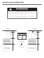 6
6
-
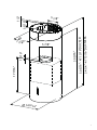 7
7
-
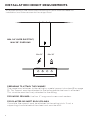 8
8
-
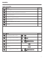 9
9
-
 10
10
-
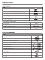 11
11
-
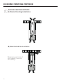 12
12
-
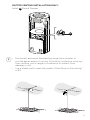 13
13
-
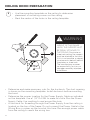 14
14
-
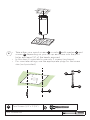 15
15
-
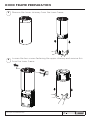 16
16
-
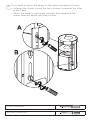 17
17
-
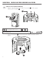 18
18
-
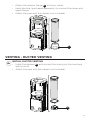 19
19
-
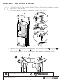 20
20
-
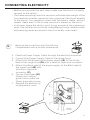 21
21
-
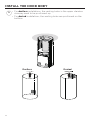 22
22
-
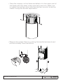 23
23
-
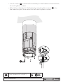 24
24
-
 25
25
-
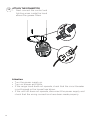 26
26
-
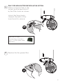 27
27
-
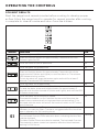 28
28
-
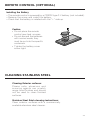 29
29
-
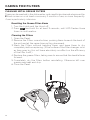 30
30
-
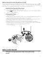 31
31
-
 32
32
-
 33
33
-
 34
34
-
 35
35
-
 36
36
-
 37
37
-
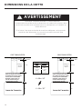 38
38
-
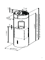 39
39
-
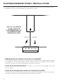 40
40
-
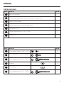 41
41
-
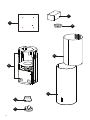 42
42
-
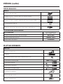 43
43
-
 44
44
-
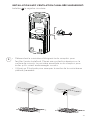 45
45
-
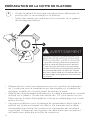 46
46
-
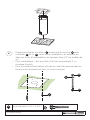 47
47
-
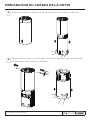 48
48
-
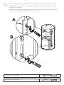 49
49
-
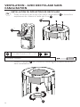 50
50
-
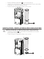 51
51
-
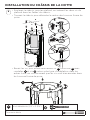 52
52
-
 53
53
-
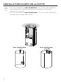 54
54
-
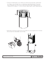 55
55
-
 56
56
-
 57
57
-
 58
58
-
 59
59
-
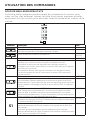 60
60
-
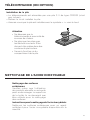 61
61
-
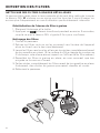 62
62
-
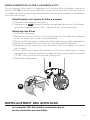 63
63
-
 64
64
-
 65
65
-
 66
66
-
 67
67
-
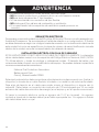 68
68
-
 69
69
-
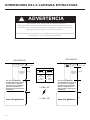 70
70
-
 71
71
-
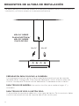 72
72
-
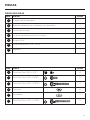 73
73
-
 74
74
-
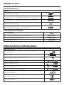 75
75
-
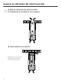 76
76
-
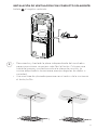 77
77
-
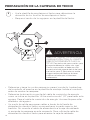 78
78
-
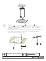 79
79
-
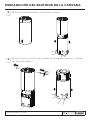 80
80
-
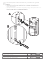 81
81
-
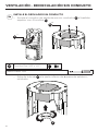 82
82
-
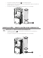 83
83
-
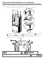 84
84
-
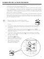 85
85
-
 86
86
-
 87
87
-
 88
88
-
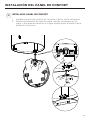 89
89
-
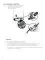 90
90
-
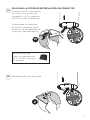 91
91
-
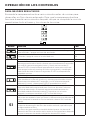 92
92
-
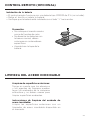 93
93
-
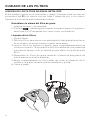 94
94
-
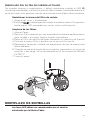 95
95
-
 96
96
-
 97
97
-
 98
98
-
 99
99
-
 100
100


Faber CYLNIS15SS600 Manual de usuario
- Categoría
- Campanas de cocina
- Tipo
- Manual de usuario
- Este manual también es adecuado para
En otros idiomas
- français: Faber CYLNIS15SS600 Manuel utilisateur
- English: Faber CYLNIS15SS600 User manual
Documentos relacionados
-
Faber CYLN15SS600 Manual de usuario
-
-
-
-
-
-
-
Liebherr NOPR30SSV Guía de instalación
-
-