
Manuale d’installazione, uso e
manutenzione Caldaia a pellet modello
Installation, use and maintenance manual
Pellet Heating Boiler model
Manuel d’installation, d’utilisation et
d’entretien Chaudière à granulés mod.
Installations-, Bedienungs- und
Wartungsanleitung
Manual de instalación, uso y
mantenimiento Caldera de pellets mod.
HR EVO 290
HR EVO 350
HR EVO 390

Manuale uso e manutenzione HR EVO 290 - 350 - 390
Pag.2
Rev.1 16/03/2018
ITA
SCHEDA PRODOTTO
PRODUCT DATASHEET
FICHE DE PRODUIT
PRODUCTKAART
PRODUKTDATENBLATT
FICHA DEL PRODUTO
EU 2015/1187
Marca / Trademark / Marque / Merk / Marke / Marca Ravelli
Modello / Model / Modèle / Model / Modell / Modelo HR EVO 290
Classe di efficienza energetica / Energy Efficiency class /Classe d’Efficacité Énergétique /
Energie-efficiëntieklasse / Energieeffizienzklasse / Clase de eficiencia energética A+
Potenza termica nominale / Rated heat output / Puissance thermique nominale /
Nominaal warmtevermogen / Wärmenennleistung / Potencia térmica nominal
27 kW
Indice di efficienza energetica /Energy Efficiency Index / Indice de eficiencia energética /
Energie-efficiëntie-index / Energieeffizienzindex / Índice de eficiencia energética 117
Efficienza energetica stagionale di riscaldamento di ambiente / Seasonal space heating
energy efficiency / Efficacité énergétique saisonnière pour le chauffage des locaux /
Seizoensgebonden energie-efficiëntie verwarming omgeving / Saisonenergieeffizienz für
die Raumheizung / Eficiencia energética estacional de calefacción del ambiente
80 %
Rispettare le avvertenze e le indicazioni di installazione e manutenzione periodica riportate nel manuale di
istruzioni.
Comply with the warnings and instructions concerning installation and routine maintenance provided in the
instruction manual.
Respecter les avertissements et les indications sur l’installation et l’entretien périodique fournis dans le manuel
d’instructions.
Neem de waarschuwingen en instructies voor installatie en periodiek onderhoud in acht zoals aangegeven in de
hoofdstukken van de gebruiksaanwijzing.
Beachten Sie die Warnungen und Hinweise betreffend die Installation und regelmäßige Wartung in der
Bedienungsanleitung.
Respete las advertencias y las indicaciones de instalación y mantenimiento periódico, detalladas en los capítulos del
manual de instrucciones.
27
HR EVO 290
PRODUCT DATASHEET
FICHA DO PRODUTO
ΔΕΛΤΙΟ ΠΡΟΪΟΝΤΟΣ
PRODUKTBLAD
KARTA PRODUKTU
PODATKOVNI LIST IZDELKA
EU 2015/1187
Trademark / Marca / Μάρκα / Mærke / Marka / Blagovna znamka Ravelli
Model / Modelo / Μοντέλο / Model / Model / Model HR EVO 290
Energy Efficiency class / Classe de Eficiência Energética / Κατηγορία ενεργειακής
απόδοσης / Energiklasse / Klasa efektywności energetycznej / Razred energetske
učinkovitosti
A+
Rated heat output/ Potência térmica nominal / Ονομαστική θερμική ισχύς / Nominel
termisk effekt / Nominalna moc cieplna / Nazivna vhodna toplotna moč 27 kW
Energy Efficiency Index / Índice de eficiência energética / Δείκτης ενεργειακής απόδοσης /
Indeks energieffektivitet / Wskaźnik efektywności energetycznej / Kazalo energetske
učinkovitosti
117
Seasonal space heating energy efficiency/ Eficiência energética sazonal de aquecimento
de ambiente / Εποχιακή ενεργειακή απόδοση θέρμανσης περιβάλλοντος / Årstidsbestemt
energieffektivitet for opvarmning / Sezonowa efektywność energetyczna ogrzewania
otoczenia/ Sezonska energetska učinkovitost ogrevanja prostora
80 %
Comply with the warnings and instructions concerning installation and routine maintenance provided in the
instruction manual.
Respeitar as advertências e as indicações de instalação e manutenção periódica referidas nos capítulos do manual
de instruções.
Τηρείτε τις προειδοποιήσεις και τις οδηγίες εγκατάστασης και περιοδικής συντήρησης που αναφέρονται στα
κεφάλαια του εγχειριδίου των οδηγιών.
Overhold advarslerne og angivelserne for installation og vedligeholdelse, som angivet i kapitel i brugsvejledningen.
Należy przestrzegać ostrzeżeń i wskazówek dotyczących instalacji i okresowej konserwacji podanych w rozdziałach w
instrukcji obsługi.
Upoštevajte opozorila in navodila za namestitev in redno vzdrževanje, navedena v poglavjih priročnika z navodili.
27
HR EVO 290

Manuale uso e manutenzione HR EVO 290 - 350 - 390
Pag.3
Rev.1 16/03/2018
ITA
SCHEDA PRODOTTO
PRODUCT DATASHEET
FICHE DE PRODUIT
PRODUCTKAART
PRODUKTDATENBLATT
FICHA DEL PRODUTO
EU 2015/1187
Marca / Trademark / Marque / Merk / Marke / Marca Ravelli
Modello / Model / Modèle / Model / Modell / Modelo HR EVO 350 TOUCH
Classe di efficienza energetica / Energy Efficiency class /Classe d’Efficacité Énergétique /
Energie-efficiëntieklasse / Energieeffizienzklasse / Clase de eficiencia energética A+
Potenza termica nominale / Rated heat output / Puissance thermique nominale /
Nominaal warmtevermogen / Wärmenennleistung / Potencia térmica nominal
32 kW
Indice di efficienza energetica /Energy Efficiency Index / Indice de eficiencia energética /
Energie-efficiëntie-index / Energieeffizienzindex / Índice de eficiencia energética 117
Efficienza energetica stagionale di riscaldamento di ambiente / Seasonal space heating
energy efficiency / Efficacité énergétique saisonnière pour le chauffage des locaux /
Seizoensgebonden energie-efficiëntie verwarming omgeving / Saisonenergieeffizienz für
die Raumheizung / Eficiencia energética estacional de calefacción del ambiente
80 %
Rispettare le avvertenze e le indicazioni di installazione e manutenzione periodica riportate nel manuale di
istruzioni.
Comply with the warnings and instructions concerning installation and routine maintenance provided in the
instruction manual.
Respecter les avertissements et les indications sur l’installation et l’entretien périodique fournis dans le manuel
d’instructions.
Neem de waarschuwingen en instructies voor installatie en periodiek onderhoud in acht zoals aangegeven in de
hoofdstukken van de gebruiksaanwijzing.
Beachten Sie die Warnungen und Hinweise betreffend die Installation und regelmäßige Wartung in der
Bedienungsanleitung.
Respete las advertencias y las indicaciones de instalación y mantenimiento periódico, detalladas en los capítulos del
manual de instrucciones.
32
HR EVO 350 TOUCH
PRODUCT DATASHEET
FICHA DO PRODUTO
ΔΕΛΤΙΟ ΠΡΟΪΟΝΤΟΣ
PRODUKTBLAD
KARTA PRODUKTU
PODATKOVNI LIST IZDELKA
EU 2015/1187
Trademark / Marca / Μάρκα / Mærke / Marka / Blagovna znamka Ravelli
Model / Modelo / Μοντέλο / Model / Model / Model HR EVO 350 TOUCH
Energy Efficiency class / Classe de Eficiência Energética / Κατηγορία ενεργειακής
απόδοσης / Energiklasse / Klasa efektywności energetycznej / Razred energetske
učinkovitosti
A+
Rated heat output/ Potência térmica nominal / Ονομαστική θερμική ισχύς / Nominel
termisk effekt / Nominalna moc cieplna / Nazivna vhodna toplotna moč 32 kW
Energy Efficiency Index / Índice de eficiência energética / Δείκτης ενεργειακής απόδοσης /
Indeks energieffektivitet / Wskaźnik efektywności energetycznej / Kazalo energetske
učinkovitosti
117
Seasonal space heating energy efficiency/ Eficiência energética sazonal de aquecimento
de ambiente / Εποχιακή ενεργειακή απόδοση θέρμανσης περιβάλλοντος / Årstidsbestemt
energieffektivitet for opvarmning / Sezonowa efektywność energetyczna ogrzewania
otoczenia/ Sezonska energetska učinkovitost ogrevanja prostora
80 %
Comply with the warnings and instructions concerning installation and routine maintenance provided in the
instruction manual.
Respeitar as advertências e as indicações de instalação e manutenção periódica referidas nos capítulos do manual
de instruções.
Τηρείτε τις προειδοποιήσεις και τις οδηγίες εγκατάστασης και περιοδικής συντήρησης που αναφέρονται στα
κεφάλαια του εγχειριδίου των οδηγιών.
Overhold advarslerne og angivelserne for installation og vedligeholdelse, som angivet i kapitel i brugsvejledningen.
Należy przestrzegać ostrzeżeń i wskazówek dotyczących instalacji i okresowej konserwacji podanych w rozdziałach w
instrukcji obsługi.
Upoštevajte opozorila in navodila za namestitev in redno vzdrževanje, navedena v poglavjih priročnika z navodili.
32
HR EVO 350 TOUCH

Manuale uso e manutenzione HR EVO 290 - 350 - 390
Pag.4
Rev.1 16/03/2018
ITA
SCHEDA PRODOTTO
PRODUCT DATASHEET
FICHE DE PRODUIT
PRODUCTKAART
PRODUKTDATENBLATT
FICHA DEL PRODUTO
EU 2015/1187
Marca / Trademark / Marque / Merk / Marke / Marca Ravelli
Modello / Model / Modèle / Model / Modell / Modelo HR EVO 390
Classe di efficienza energetica / Energy Efficiency class /Classe d’Efficacité Énergétique /
Energie-efficiëntieklasse / Energieeffizienzklasse / Clase de eficiencia energética A+
Potenza termica nominale / Rated heat output / Puissance thermique nominale /
Nominaal warmtevermogen / Wärmenennleistung / Potencia térmica nominal
35 kW
Indice di efficienza energetica /Energy Efficiency Index / Indice de eficiencia energética /
Energie-efficiëntie-index / Energieeffizienzindex / Índice de eficiencia energética 116
Efficienza energetica stagionale di riscaldamento di ambiente / Seasonal space heating
energy efficiency / Efficacité énergétique saisonnière pour le chauffage des locaux /
Seizoensgebonden energie-efficiëntie verwarming omgeving / Saisonenergieeffizienz für
die Raumheizung / Eficiencia energética estacional de calefacción del ambiente
79 %
Rispettare le avvertenze e le indicazioni di installazione e manutenzione periodica riportate nel manuale di
istruzioni.
Comply with the warnings and instructions concerning installation and routine maintenance provided in the
instruction manual.
Respecter les avertissements et les indications sur l’installation et l’entretien périodique fournis dans le manuel
d’instructions.
Neem de waarschuwingen en instructies voor installatie en periodiek onderhoud in acht zoals aangegeven in de
hoofdstukken van de gebruiksaanwijzing.
Beachten Sie die Warnungen und Hinweise betreffend die Installation und regelmäßige Wartung in der
Bedienungsanleitung.
Respete las advertencias y las indicaciones de instalación y mantenimiento periódico, detalladas en los capítulos del
manual de instrucciones.
35
HR EVO 390
PRODUCT DATASHEET
FICHA DO PRODUTO
ΔΕΛΤΙΟ ΠΡΟΪΟΝΤΟΣ
PRODUKTBLAD
KARTA PRODUKTU
PODATKOVNI LIST IZDELKA
EU 2015/1187
Trademark / Marca / Μάρκα / Mærke / Marka / Blagovna znamka Ravelli
Model / Modelo / Μοντέλο / Model / Model / Model HR EVO 390
Energy Efficiency class / Classe de Eficiência Energética / Κατηγορία ενεργειακής
απόδοσης / Energiklasse / Klasa efektywności energetycznej / Razred energetske
učinkovitosti
A+
Rated heat output/ Potência térmica nominal / Ονομαστική θερμική ισχύς / Nominel
termisk effekt / Nominalna moc cieplna / Nazivna vhodna toplotna moč 35 kW
Energy Efficiency Index / Índice de eficiência energética / Δείκτης ενεργειακής απόδοσης /
Indeks energieffektivitet / Wskaźnik efektywności energetycznej / Kazalo energetske
učinkovitosti
116
Seasonal space heating energy efficiency/ Eficiência energética sazonal de aquecimento
de ambiente / Εποχιακή ενεργειακή απόδοση θέρμανσης περιβάλλοντος / Årstidsbestemt
energieffektivitet for opvarmning / Sezonowa efektywność energetyczna ogrzewania
otoczenia/ Sezonska energetska učinkovitost ogrevanja prostora
79 %
Comply with the warnings and instructions concerning installation and routine maintenance provided in the
instruction manual.
Respeitar as advertências e as indicações de instalação e manutenção periódica referidas nos capítulos do manual
de instruções.
Τηρείτε τις προειδοποιήσεις και τις οδηγίες εγκατάστασης και περιοδικής συντήρησης που αναφέρονται στα
κεφάλαια του εγχειριδίου των οδηγιών.
Overhold advarslerne og angivelserne for installation og vedligeholdelse, som angivet i kapitel i brugsvejledningen.
Należy przestrzegać ostrzeżeń i wskazówek dotyczących instalacji i okresowej konserwacji podanych w rozdziałach w
instrukcji obsługi.
Upoštevajte opozorila in navodila za namestitev in redno vzdrževanje, navedena v poglavjih priročnika z navodili.
35
HR EVO 390

Manuale uso e manutenzione HR EVO 290 - 350 - 390
Pag.5
Rev.1 16/03/2018
ITA
Dichiarazione di conformità UE /EU Declaration of Conformity
(DoC)
Il sottoscritto, rappresentante il seguente costruttore
The undersigned, representative of the following manufacturer
Aico S.p.A.
Via A. Kupfer, 31
25036 Palazzolo s/O (Bs)
ph: +39 030 74 02 939, e-mail: info@ravelligroup.it
DICHIARA che la dichiarazione viene rilasciata sotto la propria responsabilità e si riferisce al seguente
prodotto:
DECLARES that the DoC is issued under our sole responsibility and belongs to the following product:
Descrizione
Description
Caldaia a pellet
Pellet boiler
Marchio
Trademark Ravelli
Modello
Model HR EVO 290
L'oggetto della dichiarazione di cui sopra è conforme alla pertinente normativa di armonizzazione
dell'Unione:
2006/42/CE, Direttiva Macchine (MD)
2014/30/UE, Direttiva Compatibilità Elettromagnetica (EMCD)
2014/35/UE, Direttiva Bassa Tensione (LVD)
2011/65/UE, Direttiva sulla restrizione dell’uso di determinate sostanze pericolose nelle
apparecchiature elettriche ed elettroniche (Direttiva RoHS)
Direttiva 2009/125/CE, Ecodesign
The object of the declaration described above is in conformity with the relevant Union harmonisation
legislation:
2006/42/CE, Machinery Directive (MD)
2014/30/EU, ElectroMagnetic Compatibility Directive (EMCD)
2014/35/EU, Low Voltage Directive (LVD)
2011/65/EU, Restriction of the use of certain hazardous substances Directive (RoHS Directive)
2009/125/EC Directive, Ecodesign
Sono state applicate le seguenti norme armonizzate e/o specifiche tecniche:
The following harmonised standards and/or technical specifications have been applied
EN 303-5 EN 61000-6-2
EN 61000-6-3
EN 60335-1
EN 60335-2-102
EN 62233
EN 50581 (EU) 2015/1189
Verifica EN 303-5 effettuata da parte dell’ente notificato TÜV Rheinland Energy GmbH (NB 2456), Am
Grauen Stein D-51105, Koln (DE)
EN 303-5 tests carried out by the notified laboratory TÜV Rheinland Energy GmbH (NB 2456), Am Grauen
Stein D-51105, Koln (DE)
Luogo e data Palazzolo Sull'Oglio (BS), Firma____________________________
Place and date 10/10/2017 Sign (Giovanni Scarlini, CEO)

Manuale uso e manutenzione HR EVO 290 - 350 - 390
Pag.6
Rev.1 16/03/2018
ITA
Dichiarazione di conformità UE /EU Declaration of Conformity
(DoC)
Il sottoscritto, rappresentante il seguente costruttore
The undersigned, representative of the following manufacturer
Aico S.p.A.
Via A. Kupfer, 31
25036 Palazzolo s/O (Bs)
ph: +39 030 74 02 939, e-mail: info@ravelligroup.it
DICHIARA che la dichiarazione viene rilasciata sotto la propria responsabilità e si riferisce al seguente
prodotto:
DECLARES that the DoC is issued under our sole responsibility and belongs to the following product:
Descrizione
Description
Caldaia a pellet
Pellet boiler
Marchio
Trademark Ravelli
Modello
Model HR EVO 350
L'oggetto della dichiarazione di cui sopra è conforme alla pertinente normativa di armonizzazione
dell'Unione:
2006/42/CE, Direttiva Macchine (MD)
2014/30/UE, Direttiva Compatibilità Elettromagnetica (EMCD)
2014/35/UE, Direttiva Bassa Tensione (LVD)
2011/65/UE, Direttiva sulla restrizione dell’uso di determinate sostanze pericolose nelle
apparecchiature elettriche ed elettroniche (Direttiva RoHS)
Direttiva 2009/125/CE, Ecodesign
The object of the declaration described above is in conformity with the relevant Union harmonisation
legislation:
2006/42/CE, Machinery Directive (MD)
2014/30/EU, ElectroMagnetic Compatibility Directive (EMCD)
2014/35/EU, Low Voltage Directive (LVD)
2011/65/EU, Restriction of the use of certain hazardous substances Directive (RoHS Directive)
2009/125/EC Directive, Ecodesign
Sono state applicate le seguenti norme armonizzate e/o specifiche tecniche:
The following harmonised standards and/or technical specifications have been applied
EN 303-5 EN 61000-6-2
EN 61000-6-3
EN 60335-1
EN 60335-2-102
EN 62233
EN 50581 (EU) 2015/1189
Verifica EN 303-5 effettuata da parte dell’ente notificato TÜV Rheinland Energy GmbH (NB 2456), Am
Grauen Stein D-51105, Koln (DE)
EN 303-5 tests carried out by the notified laboratory TÜV Rheinland Energy GmbH (NB 2456), Am Grauen
Stein D-51105, Koln (DE)
Luogo e data Palazzolo Sull'Oglio (BS), Firma____________________________
Place and date 10/10/2017 Sign (Giovanni Scarlini, CEO)

Manuale uso e manutenzione HR EVO 290 - 350 - 390
Pag.7
Rev.1 16/03/2018
ITA
Dichiarazione di conformità UE /EU Declaration of Conformity
(DoC)
Il sottoscritto, rappresentante il seguente costruttore
The undersigned, representative of the following manufacturer
Aico S.p.A.
Via A. Kupfer, 31
25036 Palazzolo s/O (Bs)
ph: +39 030 74 02 939, e-mail: info@ravelligroup.it
DICHIARA che la dichiarazione viene rilasciata sotto la propria responsabilità e si riferisce al seguente
prodotto:
DECLARES that the DoC is issued under our sole responsibility and belongs to the following product:
Descrizione
Description
Caldaia a pellet
Pellet boiler
Marchio
Trademark Ravelli
Modello
Model HR EVO 390
L'oggetto della dichiarazione di cui sopra è conforme alla pertinente normativa di armonizzazione
dell'Unione:
2006/42/CE, Direttiva Macchine (MD)
2014/30/UE, Direttiva Compatibilità Elettromagnetica (EMCD)
2014/35/UE, Direttiva Bassa Tensione (LVD)
2011/65/UE, Direttiva sulla restrizione dell’uso di determinate sostanze pericolose nelle
apparecchiature elettriche ed elettroniche (Direttiva RoHS)
Direttiva 2009/125/CE, Ecodesign
The object of the declaration described above is in conformity with the relevant Union harmonisation
legislation:
2006/42/CE, Machinery Directive (MD)
2014/30/EU, ElectroMagnetic Compatibility Directive (EMCD)
2014/35/EU, Low Voltage Directive (LVD)
2011/65/EU, Restriction of the use of certain hazardous substances Directive (RoHS Directive)
2009/125/EC Directive, Ecodesign
Sono state applicate le seguenti norme armonizzate e/o specifiche tecniche:
The following harmonised standards and/or technical specifications have been applied
EN 303-5 EN 61000-6-2
EN 61000-6-3
EN 60335-1
EN 60335-2-102
EN 62233
EN 50581 (EU) 2015/1189
Verifica EN 303-5 effettuata da parte dell’ente notificato TÜV Rheinland Energy GmbH (NB 2456), Am
Grauen Stein D-51105, Koln (DE)
EN 303-5 tests carried out by the notified laboratory TÜV Rheinland Energy GmbH (NB 2456), Am Grauen
Stein D-51105, Koln (DE)
Luogo e data Palazzolo Sull'Oglio (BS), Firma____________________________
Place and date 10/10/2017 Sign (Giovanni Scarlini, CEO)

Manuale uso e manutenzione HR EVO 290 - 350 - 390
Pag.8
Rev.1 16/03/2018
ITA
Manuale d’installazione, uso e manutenzione Caldaia a pellet
modello
HR EVO 290
HR EVO 350
HR EVO 390
Prefazione
Gentile Cliente, la ringraziamo per la preferenza accordataci scegliendo una nostra caldaia.
La invitiamo a leggere attentamente questo manuale prima di accingersi alla sua installazione e al suo utilizzo, al ne di poterne
sfruttare al meglio e in totale sicurezza tutte le caratteristiche. In esso sono contenuti tutte le informazioni necessarie per una corretta
installazione, messa in funzione, modalità di utilizzo, pulizia, manutenzione, ecc.
Conservare il presente manuale in luogo idoneo, non mettere da parte questo manuale senza averlo letto.
Installazioni scorrette, manutenzioni non effettuate correttamente, uso improprio del prodotto sollevano il Costruttore da ogni
eventuale danno derivante dall’uso della caldaia.
Per ulteriori chiarimenti o necessità contatti il suo Centro di Assistenza Tecnica Autorizzata da Ravelli.
Tutti i diritti sono riservati. Nessuna parte di questo manuale d’istruzioni potrà essere riprodotta o trasmessa con qualsiasi mezzo
elettronico o meccanico, incluso fotocopia, registrazione o qualsiasi altro sistema di memorizzazione, per altri propositi che non siano
l’uso esclusivamente personale dell’acquirente, senza espresso permesso scritto del Costruttore.

Manuale uso e manutenzione HR EVO 290 - 350 - 390
Pag.9
Rev.1 16/03/2018
ITA
Sommario
Prefazione ......................................................................................................................................................................................2
IDENTIFICAZIONE ........................................................................................................................................5
Identicazione della caldaia .........................................................................................................................................................5
Identicazione del costruttore .....................................................................................................................................................5
Etichetta di identicazione ...........................................................................................................................................................5
Norme di riferimento .....................................................................................................................................................................5
GARANZIA ................................................................................................................................................... 10
Certicato di garanzia .................................................................................................................................................................10
Condizioni di garanzia ................................................................................................................................................................10
Info e problemi .............................................................................................................................................................................10
INFORMAZIONI GENERALI ........................................................................................................................11
Fornitura e conservazione ......................................................................................................................................................... 11
Lingua .......................................................................................................................................................................................... 11
Simbologia utilizzata all’interno del manuale ..........................................................................................................................11
SICUREZZE ...............................................................................................................................................................................11
Avvertenze generali di sicurezza ..............................................................................................................................................11
Rischi residui ..............................................................................................................................................................................12
Sicurezza scarico fumi ................................................................................................................................................................12
Sicurezza sovrappressione in camera di combustione ...........................................................................................................12
Surriscaldamento- termostati di sicurezza ...............................................................................................................................12
Sicurezza contro il ritorno di amma sul canale alimentazione pellet ...................................................................................13
Dispositivo elettrico di protezione dalla sovracorrente ...........................................................................................................13
Sicurezza sovrappressione circuito idraulico ..........................................................................................................................13
Guasto ventilatore estrazione fumi ...........................................................................................................................................13
Sicurezza apertura porta fuoco-porta cenere ...........................................................................................................................13
Uso previsto .................................................................................................................................................................................13
DESCRIZIONE DELLA CALDAIA ..................................................................................................................13
Uso scorretto ragionevolmente prevedibile ............................................................................................................................13
Obblighi e divieti .........................................................................................................................................................................13
Obblighi ........................................................................................................................................................................................13
eseguire le operazioni di pulizia nei tempi indicati nel presente manuale; ...........................................................................13
utilizzare ricambi originali consigliati dal Costruttore. ............................................................................................................13
Divieti ...........................................................................................................................................................................................14
CARATTERISTICHE TECNICHE ..................................................................................................................14
Dimensioni ed ingombri .............................................................................................................................................................15
Accessori in dotazione La dotazione è comprensiva di: ............................................................................................................17
Messa fuori servizio della caldaia ..............................................................................................................................................17
TRASPORTO E INSTALLAZIONE ................................................................................................................ 17
Avvertenze di sicurezza per il trasporto e l’installazione .......................................................................................................17
Condizioni di fornitura , trasporto e immagazzinamento .......................................................................................................17
Luogo d’installazione, posizionamento e sicurezza antincendio ...........................................................................................19
Predisposizioni per il sistema evacuazione fumi ....................................................................................................................20
Canna fumaria .............................................................................................................................................................................20
Comignolo ...................................................................................................................................................................................20
Installazione ................................................................................................................................................................................20
Requisiti del locale di installazione ..........................................................................................................................................21
Esempi di installazione ...............................................................................................................................................................22
Collegamento elettrico ...............................................................................................................................................................24
Schema elettrico ..........................................................................................................................................................................24
Sicurezze per impianto a vaso chiuso ......................................................................................................................................25
Sicurezze per impianto a vaso aperto .......................................................................................................................................25
Carico acqua impianto ................................................................................................................................................................25
Caratteristiche acqua d’impianto ...............................................................................................................................................26
Impianto sanitario ......................................................................................................................................................................26
Impianto con pompe per sanitario ............................................................................................................................................27
Collaudo e messa in servizio .....................................................................................................................................................29
Veriche prima dell’accensione ................................................................................................................................................29
USO DELLA CALDAIA ................................................................................................................................. 30
Premessa ......................................................................................................................................................................................30
Accensione .................................................................................................................................................................................31
Controllo prima dell’accensione ...............................................................................................................................................31
Fase di avvio ................................................................................................................................................................................31
Fase di lavoro ..............................................................................................................................................................................32
Modica impostazione temperatura acqua ...............................................................................................................................33
Acqua calda sanitaria con scambiatore rapido ........................................................................................................................33
Acqua calda sanitaria con bollitore ad accumulo ....................................................................................................................33
Impianto con puffer/ accumulatore di calore ............................................................................................................................33
Pulizia del braciere .....................................................................................................................................................................33
Spegnimento ................................................................................................................................................................................34
Menu ............................................................................................................................................................................................34
Menu 01 – Set crono ....................................................................................................................................................................36
Menu 02 – Regolazioni utente ....................................................................................................................................................37

Manuale uso e manutenzione HR EVO 290 - 350 - 390
Pag.10
Rev.1 16/03/2018
ITA
Menu 03 – Set utente ...................................................................................................................................................................37
Menu 05 – Tarature Tecnico .....................................................................................................................................................37
Termostato - cronotermostato esterno .....................................................................................................................................38
Periodo di inattività (ne stagione) ............................................................................................................................................38
MANUTENZIONE DELLA CALDAIA .............................................................................................................38
Pulizia ...........................................................................................................................................................................................39
Pulizia braciere e del porta braciere ..........................................................................................................................................39
Pulizia della camera di combustione ........................................................................................................................................39
Pulizia contenitore cenere .........................................................................................................................................................39
Pulizia scambiatori con il dispositivo scuoti-turbolatori .........................................................................................................39
Manutenzione straordinaria ........................................................................................................................................................40
Smontaggio rivestimento caldaia ..............................................................................................................................................40
Sostituzione guarnizioni porta camera di combustione e sportello cassetto ceneri ...........................................................40
Pulizia debimetro .........................................................................................................................................................................40
Pulizia raccordo fumi – canna fumaria ......................................................................................................................................40
Componenti interni della caldaia ...............................................................................................................41
Premessa ......................................................................................................................................................................................41
Componenti idraulici di serie .....................................................................................................................................................42
RICERCA GUASTI ........................................................................................................................................ 42
Gestione degli allarmi .................................................................................................................................................................42
INSTALLATORE ...........................................................................................................................................45
Menu installatore .......................................................................................................................................................................45

Manuale uso e manutenzione HR EVO 290 - 350 - 390
Pag.11
Rev.1 16/03/2018
ITA
IDENTIFICAZIONE
Identificazione della caldaia
Tipologia di prodotto CALDAIA A PELLET
Modello HR EVO 290- HR EVO 350- HR EV0 390
Identificazione del costruttore
Costruttore Ravelli presso AICO S.p.A.
Via Kupfer, 31 - 25036 Palazzolo sull’Oglio (BS) ITALY
Tel. +39 030 7402939
Fax +39 030 7301758
www.ravelligroup.it
Etichetta di identicazione
Sulle caldaie è installata un’ etichetta di identicazione sulla quale sono incisi i dati della stessa
Norme di riferimento
Le caldaie, oggetto del presente manuale, sono conformi alle seguenti direttive:
2006/42/CE DIRETTIVA MACCHINE
2014/3/0/UE DIRETTIVA PER LA COMPATIBILITÀ ELETTROMAGNETICA
2014/35/UE DIRETTIVA BASSA TENSIONE
2011/65/UE DIRETTIVA SULLA RESTRIZIONE DELL’USO DI DETERMINATE SOSTANZE PERICOLOSE NELLE
APPARECCHIATURE ELETTRICHE ED ELETTRONICHE
E alle seguenti norme armonizzate:
EN 303-5
EN 61000-6- 2
EN 61000-6- 3
EN 60335-1
EN 60335-2- 102
EN 62233
EN 50581
Tutti i regolamenti locali, inclusi quelli riferiti alle Norme nazionali ed europee devono essere rispettati nell’installazione dell’apparecchio.

Manuale uso e manutenzione HR EVO 290 - 350 - 390
Pag.12
Rev.1 16/03/2018
ITA
GARANZIA
Certicato di garanzia
Ravelli ringrazia per la fiducia accordata con l’acquisto di un suo prodotto ed invita l’acquirente a:
• prendere visione delle istruzioni per l’installazione, utilizzo e manutenzione del prodotto.
• prendere visione delle condizioni di garanzia sotto riportate.
Condizioni di garanzia
La garanzia al Cliente viene riconosciuta dal Rivenditore secondo i termini di legge. Il tagliando di garanzia deve essere compilato in
tutte le sue parti. Il Cliente ha la responsabilità di verificare l’avvenuta compilazione e spedizione da parte del Rivenditore (o occuparsi
direttamente della spedizione) del tagliando di garanzia e della copia dello scontrino fiscale/fattura entro 8 giorni dall’acquisto.
Il tagliando di garanzia e la copia dello scontrino fiscale /fattura devono essere spediti al seguente indirizzo:
Ravelli presso Aico SpA
Via Kupfer, 31
25036 Palazzolo s/O
Brescia (ITALIA)
Il Rivenditore riconosce la garanzia solamente nel caso in cui non ci siano state manomissioni del prodotto e solo se l’installazione sia stata
fatta a norma e secondo le prescrizioni del Costruttore.
La garanzia limitata copre i difetti dei materiali di fabbricazione, purché il prodotto non abbia subito rotture causate da un uso non corretto,
incuria, errato allacciamento, manomissioni, errori di installazione.
La garanzia decade se anche una sola prescrizione riportata in questo manuale non viene rispettata.
Non sono coperti da garanzia:
• i refrattari della camera di combustione;
• il vetro della porta;
• le guarnizioni;
• la verniciatura;
• la griglia di combustione in acciaio inossidabile o in ghisa;
• le maioliche a colo;
• eventuali danni arrecati da una inadeguata installazione e/o utilizzo del prodotto e/o mancanze del consumatore.
L’impiego di pellet di qualità scadente o di qualsiasi altro combustibile non autorizzato potrebbe danneggiare componenti del prodotto
determinando la cessazione della garanzia su di essi e l’annessa responsabilità del produttore.
Pertanto si consiglia l’utilizzo di pellet di buona qualità che risponde ai requisiti elencati nel capitolo dedicato.
Tutti i danni causati dal trasporto non sono riconosciuti, per questo motivo si raccomanda di controllare accuratamente la merce al
ricevimento, avvisando immediatamente il Rivenditore di ogni eventuale danno.
Info e problemi
I Rivenditori autorizzati Ravelli fruiscono di una rete di Centri di Assistenza Tecnica addestrati per soddisfare le esigenze dei Clienti. Per
qualsiasi informazione o richiesta di assistenza, preghiamo il Cliente di contattare il proprio Rivenditore o Centro Assistenza Tecnica.

Manuale uso e manutenzione HR EVO 290 - 350 - 390
Pag.13
Rev.1 16/03/2018
ITA
INFORMAZIONI GENERALI
Fornitura e conservazione
Il manuale è fornito in formato cartaceo.
Conservare il presente manuale a corredo della caldaia, in modo da poter essere facilmente consultato dall’utente.
Il manuale è parte integrante ai ni della sicurezza, pertanto:
• deve essere conservato integro in tutte le sue parti. Qualora fosse smarrito o risultasse rovinato occorre richiederne
immediatamente una copia;
• deve seguire la caldaia no alla demolizione (anche in caso di spostamenti, vendita, noleggio, aftto, ecc...).
Ravelli declina ogni responsabilità per uso improprio della caldaia e/o per danni causati in seguito ad operazioni non contemplate
nella documentazione tecnica.
Lingua
Il manuale originale è stato redatto in lingua italiana.
Eventuali traduzioni in lingue aggiuntive devono essere effettuate partendo dalle istruzioni originali.
Il Costruttore si ritiene responsabile per le informazioni contenute nelle istruzioni originali; le traduzioni in lingue diverse non possono
essere completamente vericate, per cui se viene rilevata un’incongruenza è necessario attenersi al testo in lingua originale o
contattare il nostro Ufcio Documentazione Tecnica.
Simbologia utilizzata all’interno del manuale
simbolo denizione
! IMPORTANTE Simbolo utilizzato per identicare informazioni di particolare importanza all’interno del
manuale. Le informazioni riguardano anche la sicurezza degli utenti coinvolti nell’utilizzo
della caldaia.
Simbolo utilizzato per identicare avvertenze importanti per la sicurezza dell’utente e/o
della caldaia.
SICUREZZE
Avvertenze generali di sicurezza
! IMPORTANTE Leggere attentamente il presente manuale di istruzioni prima dell’installazione e
dell’utilizzo della caldaia. Il mancato rispetto di quanto prescritto nel presente manuale
può comportare il decadimento della garanzia e/o provocare danni a cose e/o persone.
L’installazione, il collegamento elettrico, la verifica dell’impianto, la verifica del funzionamento e la taratura iniziale
della caldaia devono essere eseguite esclusivamente da personale qualificato ed autorizzato.
Non utilizzare la caldaia come inceneritore o in qualsiasi altro modo diverso da quello per cui è stato concepito.
Non utilizzare combustibile diverso dal pellet. È severamente vietato l’utilizzo di combustibili liquidi e di legna
tradizionale.
Non aprire la porta della caldaia durante il suo funzionamento. È vietato far funzionare la caldaia con la porta
aperta o con il vetro rotto.
È vietato apportare modiche non autorizzate alla caldaia.
La caldaia deve essere collegata ad una canna fumaria singola che garantisca il tiraggio dichiarato dal Costruttore
e che rispetti le norme di installazione previste nel luogo di installazione.
Il locale dove è installata la caldaia deve essere dotato di presa d’aria.
Prima di utilizzare la caldaia occorre conoscere la posizione e la funzione dei comandi.
In caso di incendio della canna fumaria, spegnere immediatamente la caldaia tramite il pulsante sul display, in
modo da avviare la pulizia finale (non scollegare l’alimentazione elettrica e non operare sull’interruttore I/O posto
sul retro della caldaia). Chiamare i Vigili del Fuoco.
Verificare che l’impianto elettrico e le prese siano adeguati all’assorbimento massimo dell’apparecchio riportato
sull’etichetta e sul presente manuale.
Collegare l’apparecchio all’impianto di riscaldamento; esso non può in nessun caso essere usato senza
l’allacciamento idraulico e senza il caricamento dell’acqua nella caldaia e nell’impianto.

Manuale uso e manutenzione HR EVO 290 - 350 - 390
Pag.14
Rev.1 16/03/2018
ITA
La spina di alimentazione deve essere facilmente accessibile.
Utilizzare solo parti di ricambio originali. Qualsiasi manomissione e/o sostituzione non autorizzata da Ravelli può
causare pericoli per l’incolumità dell’utente.
L’apparecchio può essere utilizzato da bambini di età non inferiore a 8 anni e da persone con ridotte capacità
siche, sensoriali o mentali, o prive di esperienza o della necessaria conoscenza, purché sotto sorveglianza
oppure dopo che le stesse abbiano ricevuto istruzioni relative all’uso sicuro dell’apparecchio e alla comprensione
dei pericoli ad esso inerenti. I bambini non devono giocare con l’apparecchio. La pulizia e la manutenzione
destinata ad essere effettuata dall’utilizzatore non deve essere effettuata da bambini senza sorveglianza.
Posizionare il cavo di alimentazione elettrica ed eventuali cavi di sensori esterni in modo da evitare il contatto
con le parti calde dell’apparecchio.
E’ vietato il funzionamento dell’apparecchio con la porta della camera di combustione e/o la porta del cassetto
cenere aperte.
E’ vietato manipolare sostanze facilmente inammabili o esplosive nelle vicinanze della caldaia durante il suo
funzionamento.
Evitare il contatto diretto con le parti dell’apparecchio che durante il funzionamento possono surriscaldarsi.
E’ vietato modicare i dispositivi di sicurezza o di regolazione.
Prima di ogni manutenzione staccare l’alimentazione elettrica dalla caldaia ed operare solo con caldaia fredda.
In caso di anomalie di funzionamento, la caldaia può essere riaccesa solo dopo avere ripristinato la causa del problema ed in ogni
caso, è vietato disabilitare i sistemi di sicurezza.
Pulire regolarmente il braciere ad ogni accensione.
Evitare l’accumulo di fumo ed incombusti in fase di accensione e/o durante il normale funzionamento, l’eccessivo accumulo di pellet
incombusto nel braciere deve essere rimosso manualmente prima di procedere con una nuova accensione.
Eseguire regolarmente la manutenzione della caldaia, almeno una volta all’anno, pianicando per tempo l’intervento con il personale
del Centro di Assistenza Tecnico autorizzato.
In caso di anomalie di funzionamento, la caldaia può essere riaccesa solo dopo avere ripristinato la causa del problema, in caso
contrario contattare il servizio di Assistenza.
Il costruttore declina ogni responsabilità per uso improprio della caldaia per danni causati in seguito ad operazioni
non contemplate nella documentazione tecnica.
Rischi residui
La progettazione della caldaia è stata eseguita in modo da garantire i requisiti essenziali di sicurezza per l’utente.
La sicurezza, per quanto possibile, è stata integrata nel progetto e nella costruzione della caldaia.
Sicurezza scarico fumi
Nel normale funzionamento, la camera di combustione è in depressione garantendo la tenuta da eventuali perdite di fumo nell’ambiente.
Nel caso in cui la depressione è insufciente o lo scarico di uscita dei fumi è ostruito, il pressostato capta la mancanza di depressione
all’interno della camera di combustione e il funzionamento del motore della coclea viene interrotto avvisando l’utente dell’anomalia
con un messaggio sul pannello comandi ‘ AL8 MANCA DEPRESS ‘ o ‘ AL9 TIRAGGIO INSUFF ‘.
Sicurezza sovrappressione in camera di combustione
Eventuali e/o improvvise sovrappressioni dei fumi di combustione all’interno della camera e dei condotti di evacuazione dei fumi
vengono scaricati attraverso l’apertura delle valvole di sicurezza poste sopra la porta cenere. Durante il normale funzionamento
queste valvole sono chiuse dal proprio peso e dalla depressione della camera e garantiscono la tenuta contro l’eventuale uscita dei
fumi.
Controllare periodicamente la chiusura, lo stato di integrità del dispositivo e il relativo funzionamento.
Surriscaldamento- termostati di sicurezza
Sulla parete inferiore del serbatoio, precisamente sul canale alimentazione del pellet, e nel pozzetto termico di misura della
temperatura dell’acqua, sono posizionate due sonde di temperatura collegate ai rispettivi termostati di sicurezza che in caso di
eccessivo surriscaldamento interrompono automaticamente l’alimentazione del pellet. In tal caso l’estrattore fumi continua a funzionare
consentendo il rapido raffreddamento dell’apparecchio. L’anomalia viene visualizzata sul pannello comandi con il messaggio ‘ AL 7
SICUREZ-TERMICA ’. In caso di intervento dei termostati operare come segue:
Lasciare raffreddare la caldaia per almeno 45 minuti.

Manuale uso e manutenzione HR EVO 290 - 350 - 390
Pag.15
Rev.1 16/03/2018
ITA
Sicurezza contro il ritorno di amma sul canale alimentazione pellet
Le soluzioni che impediscono il ritorno di amma sono:
• depressione in camera di combustione;
• la forma a sifone del canale di alimentazione pellet;
• la sicurezza sulla temperatura del serbatoio.
Dispositivo elettrico di protezione dalla sovracorrente
L’apparecchio è protetto contro la sovracorrente da fusibile/i da 2A inseriti sull’alimentazione della scheda elettronica.
Sicurezza sovrappressione circuito idraulico
Eventuale sovrappressione dell’acqua all’interno della camera, per P>3 bar , viene scaricata attraverso l’intervento della valvola di
sicurezza installata sull’impianto idraulico interno alla caldaia.
È vietato manomettere i dispositivi di sicurezza.
Guasto ventilatore estrazione fumi
Se per qualsiasi motivo il ventilatore di estrazione fumi si ferma, l’alimentazione di pellet viene immediatamente interrotta, visualizzando
il messaggio ‘AL4 ASPIRAT-GUASTO’.
Sicurezza apertura porta fuoco-porta cenere
Il micro interruttore di sicurezza interviene nel momento in cui rileva l’apertura della porta della camera di combustione o della porta
del vano cenere, durante il normale funzionamento della caldaia, il controllo elettronico blocca istantaneamente l’alimentazione di
pellet visualizzando il messaggio ‘AL M PORTA APERTA’.
Uso previsto
L’apparecchiatura in oggetto è una caldaia a combustibile solido ad alimentazione automatica, destinata al riscaldamento dell’acqua
di un impianto termico, mediante la combustione di pellet di legno.
DESCRIZIONE DELLA CALDAIA
La macchina è progettata e costruita per lavorare in sicurezza se:
• viene impiegata entro i limiti dichiarati sul contratto e sul presente manuale;
• vengono seguite le procedure del manuale d’uso;
• viene effettuata la manutenzione ordinaria nei tempi e nei modi indicati;
• viene fatta eseguire tempestivamente la manutenzione straordinaria in caso di necessità;
• non vengono rimossi e/o bypassati i dispositivi di sicurezza.
Uso scorretto ragionevolmente prevedibile
L’uso scorretto ragionevolmente prevedibile, viene di seguito elencato:
• utilizzo della caldaia come inceneritore;
• utilizzo della caldaia con combustibile differente da pellet di legno;
• utilizzo della caldaia con combustibili liquidi;
Qualsiasi altro impiego dell’apparecchiatura rispetto a quello previsto deve essere preventivamente autorizzato per iscritto dal
Costruttore. In mancanza di tale autorizzazione scritta, l’impiego è da considerare “uso improprio”. È esclusa qualsiasi responsabilità
contrattuale ed extracontrattuale del Costruttore per danni causati a persone, animali o cose, da errori di installazione, di regolazione,
di manutenzione e da usi impropri.
Obblighi e divieti
Obblighi
L’utente deve:
• leggere il presente manuale di istruzioni prima di compiere qualsiasi operazione sulla caldaia;
• l’apparecchio può essere utilizzato da bambini di età non inferiore a 8 anni e da persone con ridotte capacità siche, sensoriali
o mentali, o prive di esperienza o della necessaria conoscenza, purché sotto sorveglianza;
• non utilizzare la caldaia in modo improprio;
• è severamente vietato l’utilizzo di combustibili liquidi inammabili per l’accensione;
• tenere ad opportuna distanza di sicurezza oggetti non resistenti al calore e/o inammabili;
• alimentare la caldaia solo ed esclusivamente con pellet di legna aventi le caratteristiche descritte nel presente manuale;
• collegare la caldaia ad una canna fumaria a norma;
• collegare la caldaia all’aspirazione tramite un tubo o presa d’aria dall’esterno;
• effettuare gli interventi di manutenzione sempre a caldaia spenta;
• eseguire le operazioni di pulizia nei tempi indicati nel presente manuale;
• utilizzare ricambi originali consigliati dal Costruttore.
Ripristinare il termostato premendo il pulsante vicino all’interruttore dietro la caldaia (gura a lato) dopo aver
rimosso la protezione e precisamente:
• T1 - termostato temperatura acqua caldaia;
• T2 - termostato temperatura canale alimentazione pellet.
Riavviare la caldaia come da normale avvio. La temperatura d’intervento del termostato del serbatoio pellet è
> 85°C, quella del termostato acqua: > 95°C. T1 T2
715
1300
810
1/2" F SCARICO SICUREZZA
1" M RITORNO IMPIANTO
60 (ENTRATA ARIA)
SCARICO ACQUA IMPIANTO
1"M MANDATA IMPIANTO
100 (USCITA FUMI)
197
302
332
309
Mod.
DESCRIZIONE
Data
Dis.
Appr.
MODIFICHE
CXB00100C
A3
(SHEET)
FORMATO
363.331
TOLLERANZE GENERALI SECONDO LA CLASSE UNI EN 22768-mK
GENERAL TOLERANCES AS PER UNI EN 22768-mK
1:10
lunedì 9 ottobre 2017
SCALA
(SCALE
)
DENOMINAZIONE
(DENOMINATION
)
will be legally pursued.
diritti a rigore di legge.
and must not be released to other parties without written consent any infringement
in any way utilized for the manifacture of the component of unit herein illustrated
All proprietary right reserved by Society Ravelli Group This drawing shall not be reproduced or
ne venire comunicato a terzi o riprodotto. La Societa' proprietaria tutela i propri
disegno non potra' essere comunque utilizzato per la costruzione dell' oggetto rappresentato
Proprieta' della Societa' Ravelli Group Senza autorizzazione scitta della stessa, il presente
MODIFICARE SOLO SU CAD
(CHECKED)
CONTR.
(WEIGHT)
PESO Kg
DIS.
MATERIALE
(MATERIAL)
(DESIGNER)
DATA
(DRWG NR.)
N. DISEGNO
(DATE)
CAD DRAWNING HANDLING ON CAD SYSTEM ONLY
TRATTAM. SUPERFICIALE
Posizione file di disegno:
R:\ECO-PROGETTI\00_STUFE\ARCHIVIO-VALIDI\MODELLI-SW-1\TAVOLE TECNICHE\CXB00100C\
Posizione modello 3D:
R:\ECO-PROGETTI\00_STUFE\ARCHIVIO-VALIDI\MODELLI-SW-1\CALDAIE 2017\
Ultimo salvataggio di:
ggandossi -
Data ultimo salvataggio:
lunedì 9 ottobre 2017 15:24:07
R.Aceti
-
HR EVO 290
Via Kupfer 25036 Palazzolo S/O - BRESCIA - ITALY
AICO S.P.A

Manuale uso e manutenzione HR EVO 290 - 350 - 390
Pag.16
Rev.1 16/03/2018
ITA
Divieti
L’utente non deve:
• andare a contatto con la caldaia se è a piedi nudi e con parti del corpo bagnate;
• rimuovere o modicare senza autorizzazione i dispositivi di sicurezza;
• compiere di propria iniziativa operazioni o manovre che non sono di loro competenza ovvero che possono compromettere la
sicurezza propria o di altre persone;
• versare il pellet direttamente nel braciere;
• utilizzare prodotti diversi dal pellet di legno;
• utilizzare la caldaia come inceneritore;
• utilizzare sostanze inammabili o esplosive nelle vicinanze della caldaia durante il suo funzionamento;
• utilizzare la caldaia con la porta aperta e/o vetro rovinato o rotto;
• chiudere in alcun caso le aperture di ingresso aria comburente e uscita fumi;
• utilizzare la caldaia per asciugare biancheria;
• sostituire o modicare alcuni componenti della caldaia.
CARATTERISTICHE TECNICHE
La caldaia funziona esclusivamente a pellet e permette una facile installazione con l’impianto di riscaldamento e sanitario. I sistemi
di controllo automatici di cui è dotata garantiscono una resa termica ottimale ed una completa combustione, inoltre sono presenti
dei sistemi di sicurezza atti a garantire un funzionamento sicuro sia per i componenti interni sia per l’utente. Tale apparecchio deve
essere utilizzato per il solo riscaldamento dell’acqua.
L’apparecchio installato a norma funziona con qualsiasi condizione climatica esterna, comunque in condizioni critiche (vento forte,
gelo, etc.) possono intervenire i sistemi di sicurezza che spengono la caldaia.
La caldaia è munita di pompa ad alta efcienza per il circuito di riscaldamento e di tutta la componentistica di controllo e sicurezza. In
fase di funzionamento a regime l’apparecchio genera del rumore con livelli di pressione sonora compresi tra 38 e 42 dB.
I dati riportati sono indicativi e non impegnativi e possono variare a seconda del tipo e della qualità del pellet utilizzato. Ravelli si
riserva la facoltà di apportare qualsiasi modica allo scopo di migliorare le prestazioni dei prodotti.
Caratteristiche Unità di
misura HR EVO 290 HR EVO 350 HR EVO 390
Peso netto kg 281
Classe caldaia secondo norma EN
303-5:2012 5
Potenza termica introdotta ridotta -
nominale kW 6,4 - 29,0 6,4 - 34,4 6,4 - 38,3
Potenza termica utile ridotta - nominale kW 5,78 - 27,4 5,78 - 32,4 5,78 - 34,9
Rendimento ridotta- nominale % 90,14 - 94,45 90,14 - 94,18 90,14 - 91,32
Volume riscaldabile** m3660 780 920
Consumo rid. - nom. kg/h 1,32 - 6,0 1,32 - 7,1 1,32 - 7,9
Capacità serbatoio kg 68
Autonomia rid. - nom h 51,5 - 11,3 51,5 - 9,6 51,5 - 8,6
Pressione massima acqua d’esercizio bar
(MPa)
2 - ( 0,2 )
Capacità acqua termocamera l 30
Vaso d’espansione l 8 (1 bar)
Temperatura max acqua °C 80
Tiraggio consigliato Pa
(mbar)
10 - 14
( 0,10 - 0,14 )
Temperatura fumi rid. - nom. °C 62,6 - 134,3 62,6 - 148,6 62,6 - 159,5
Portata gas di scarico rid. - nom. g/s 5,4 - 14,1 5,4 - 16,3 5,4 - 18,2
Uscita fumi mm 100
Consumo elettrico in accensione* W 440
Consumo elettrico a potenza nominale* W 130
Consumo elettrico a potenza ridotta* W 75
Consumo elettrico in stand-by* W 3
Consumo elettrico massimo pompa W 45
Alimentazione elettrica V - Hz 230V - 50Hz - 2A

Manuale uso e manutenzione HR EVO 290 - 350 - 390
Pag.17
Rev.1 16/03/2018
ITA
∆T Perdite di carico
mbar kPa
HR EVO 290 10 K (39,1 l/min) 387 38,7
20 K (19,6 l/min) 97,7 9,77
HR EVO 350 10 K (46,2 l/min) 522 52,2
20 K (23,1 l/min) 130 13,0
HR EVO 390 10 K (49,9 l/min) 625 62,5
20 K (24,9 l/min) 156 15,6
Caratteristiche del pellet
Il pellet di legno è un combustibile che si compone di segatura di legno pressata, spesso recuperata da scarti di lavorazione delle
falegnamerie. Il materiale impiegato non può contenere alcuna sostanza estranea come ad esempio colla, lacca o sostanze sintetiche.
La segatura, dopo essere stata essiccata e pulita dalle impurità, viene pressata attraverso una matrice a buchi: a causa dell’alta
pressione la segatura si riscalda attivando i leganti naturali del legno; in questo modo il pellet mantiene la sua forma anche senza
aggiunta di sostanze articiali. La densità dei pellet di legno varia a seconda del tipo di legno e può superare di 1,5 - 2 volte quella
del legno naturale.
I cilindretti hanno un diametro di 6 mm e una lunghezza variabile tra 10 e 40 mm.
La loro densità è pari a circa 650 kg/m3. A causa del basso contenuto d’acqua (< 10%) hanno un elevato contenuto energetico.
La norma UNI EN ISO 17225-2:2014 (che sostituisce la norma EN PLUS) denisce la qualità dei pellet denendo tre classi: A1, A2
e B.
Il pellet deve essere trasportato ed immagazzinato in luogo asciutto. Al contatto con l’umidità si gona, diventando quindi inutilizzabile:
pertanto si rende necessario proteggerlo dall’umidità sia durante il trasporto che durante lo stoccaggio. Mantenere il combustibile ad
adeguata distanza.
Ravelli consiglia l’utilizzo di pellet di legno certicato classe A1 e A2 secondo la norma En ISO 17225-2:2014, oppure certcato DIN
PLUS (più restrittiva della classe A1) o ONORM M 7135.
! IMPORTANTE Il pellet deve essere trasportato ed immagazzinato in un locale asciutto e privo di
umidità.
L’utilizzo di pellet con caratteristiche diverse rispetto a quello testato dal tecnico durante la 1°accensione implica una nuova taratura
dei parametri di carico pellet della caldaia, tale intervento è escluso dalla garanzia.
Dimensioni ed ingombri
HR EVO 290 HR EVO 350 HR EVO 390 Unità di
misura
Altezza 1300 1300 1300 mm
Larghezza 715 715 715 mm
Profondità 810 810 810 mm
Peso a vuoto 281 281 281 kg
TAVOLA TECNICA HR EVO 290
715
1300
810
1/2" F SCARICO SICUREZZA
1" M RITORNO IMPIANTO
60 (ENTRATA ARIA)
SCARICO ACQUA IMPIANTO
1"M MANDATA IMPIANTO
100 (USCITA FUMI)
197
302
332
309
Mod.
DESCRIZIONE
Data
Dis.
Appr.
MODIFICHE
CXB00100C
A3
(SHEET)
FORMATO
363.331
TOLLERANZE GENERALI SECONDO LA CLASSE UNI EN 22768-mK
GENERAL TOLERANCES AS PER UNI EN 22768-mK
1:10
lunedì 9 ottobre 2017
SCALA
(SCALE
)
DENOMINAZIONE
(DENOMINATION
)
will be legally pursued.
diritti a rigore di legge.
and must not be released to other parties without written consent any infringement
in any way utilized for the manifacture of the component of unit herein illustrated
All proprietary right reserved by Society Ravelli Group This drawing shall not be reproduced or
ne venire comunicato a terzi o riprodotto. La Societa' proprietaria tutela i propri
disegno non potra' essere comunque utilizzato per la costruzione dell' oggetto rappresentato
Proprieta' della Societa' Ravelli Group Senza autorizzazione scitta della stessa, il presente
MODIFICARE SOLO SU CAD
(CHECKED)
CONTR.
(WEIGHT)
PESO Kg
DIS.
MATERIALE
(MATERIAL)
(DESIGNER)
DATA
(DRWG NR.)
N. DISEGNO
(DATE)
CAD DRAWNING HANDLING ON CAD SYSTEM ONLY
TRATTAM. SUPERFICIALE
Posizione file di disegno:
R:\ECO-PROGETTI\00_STUFE\ARCHIVIO-VALIDI\MODELLI-SW-1\TAVOLE TECNICHE\CXB00100C\
Posizione modello 3D:
R:\ECO-PROGETTI\00_STUFE\ARCHIVIO-VALIDI\MODELLI-SW-1\CALDAIE 2017\
Ultimo salvataggio di:
ggandossi -
Data ultimo salvataggio:
lunedì 9 ottobre 2017 15:24:07
R.Aceti
-
HR EVO 290
Via Kupfer 25036 Palazzolo S/O - BRESCIA - ITALY
AICO S.P.A
0
10
20
30
40
0
100
200
300
400
0 10 20 30 40
Δp (kPa)
Δp (mbar)
Q (l/min)

Manuale uso e manutenzione HR EVO 290 - 350 - 390
Pag.18
Rev.1 16/03/2018
ITA
TAVOLA TECNICA HR EVO 350
715
1300
810
1/2" F SCARICO SICUREZZA
1" M RITORNO IMPIANTO
60 (ENTRATA ARIA)
SCARICO ACQUA IMPIANTO
1"M MANDATA IMPIANTO
100 (USCITA FUMI)
197
302
332
309
Mod.
DESCRIZIONE
Data
Dis.
Appr.
MODIFICHE
C2B00100C
A3
(SHEET)
FORMATO
363.331
TOLLERANZE GENERALI SECONDO LA CLASSE UNI EN 22768-mK
GENERAL TOLERANCES AS PER UNI EN 22768-mK
1:10
lunedì 9 ottobre 2017
SCALA
(SCALE
)
DENOMINAZIONE
(DENOMINATION
)
will be legally pursued.
diritti a rigore di legge.
and must not be released to other parties without written consent any infringement
in any way utilized for the manifacture of the component of unit herein illustrated
All proprietary right reserved by Society Ravelli Group This drawing shall not be reproduced or
ne venire comunicato a terzi o riprodotto. La Societa' proprietaria tutela i propri
disegno non potra' essere comunque utilizzato per la costruzione dell' oggetto rappresentato
Proprieta' della Societa' Ravelli Group Senza autorizzazione scitta della stessa, il presente
MODIFICARE SOLO SU CAD
(CHECKED)
CONTR.
(WEIGHT)
PESO Kg
DIS.
MATERIALE
(MATERIAL)
(DESIGNER)
DATA
(DRWG NR.)
N. DISEGNO
(DATE)
CAD DRAWNING HANDLING ON CAD SYSTEM ONLY
TRATTAM. SUPERFICIALE
Posizione file di disegno:
R:\ECO-PROGETTI\00_STUFE\ARCHIVIO-VALIDI\MODELLI-SW-1\TAVOLE TECNICHE\C2B00100C\
Posizione modello 3D:
R:\ECO-PROGETTI\00_STUFE\ARCHIVIO-VALIDI\MODELLI-SW-1\CALDAIE 2017\
Ultimo salvataggio di:
ggandossi -
Data ultimo salvataggio:
venerdì 20 ottobre 2017 16:59:35
R.Aceti
-
HR EVO 350
Via Kupfer 25036 Palazzolo S/O - BRESCIA - ITALY
AICO S.P.A
715
1300
810
1/2" F SCARICO SICUREZZA
1" M RITORNO IMPIANTO
60 (ENTRATA ARIA)
SCARICO ACQUA IMPIANTO
1"M MANDATA IMPIANTO
100 (USCITA FUMI)
197
302
332
309
Mod.
DESCRIZIONE
Data
Dis.
Appr.
MODIFICHE
C5B00100C
A3
(SHEET)
FORMATO
363.331
TOLLERANZE GENERALI SECONDO LA CLASSE UNI EN 22768-mK
GENERAL TOLERANCES AS PER UNI EN 22768-mK
1:10
lunedì 9 ottobre 2017
SCALA
(SCALE
)
DENOMINAZIONE
(DENOMINATION
)
will be legally pursued.
diritti a rigore di legge.
and must not be released to other parties without written consent any infringement
in any way utilized for the manifacture of the component of unit herein illustrated
All proprietary right reserved by Society Ravelli Group This drawing shall not be reproduced or
ne venire comunicato a terzi o riprodotto. La Societa' proprietaria tutela i propri
disegno non potra' essere comunque utilizzato per la costruzione dell' oggetto rappresentato
Proprieta' della Societa' Ravelli Group Senza autorizzazione scitta della stessa, il presente
MODIFICARE SOLO SU CAD
(CHECKED)
CONTR.
(WEIGHT)
PESO Kg
DIS.
MATERIALE
(MATERIAL)
(DESIGNER)
DATA
(DRWG NR.)
N. DISEGNO
(DATE)
CAD DRAWNING HANDLING ON CAD SYSTEM ONLY
TRATTAM. SUPERFICIALE
Posizione file di disegno:
R:\ECO-PROGETTI\00_STUFE\ARCHIVIO-VALIDI\MODELLI-SW-1\TAVOLE TECNICHE\C5B00100C\
Posizione modello 3D:
R:\ECO-PROGETTI\00_STUFE\ARCHIVIO-VALIDI\MODELLI-SW-1\CALDAIE 2017\
Ultimo salvataggio di:
ggandossi -
Data ultimo salvataggio:
lunedì 9 ottobre 2017 15:47:22
R.Aceti
-
HR EVO 390
Via Kupfer 25036 Palazzolo S/O - BRESCIA - ITALY
AICO S.P.A
TAVOLA TECNICA HR EVO 390

Manuale uso e manutenzione HR EVO 290 - 350 - 390
Pag.19
Rev.1 16/03/2018
ITA
Accessori in dotazione
La dotazione è comprensiva di:
• Manuale d’installazione, uso e manutenzione;
• Chiave di apertura – chiusura.
Messa fuori servizio della caldaia
La demolizione e lo smaltimento della caldaia è ad esclusivo carico e responsabilità del proprietario che dovrà agire in osservanza
delle leggi vigenti nel proprio Paese in materia di sicurezza, rispetto e tutela dell’ambiente.
Alla ne della sua vita utile, il prodotto non deve essere smaltito insieme ai riuti urbani. Può essere consegnato presso gli appositi
centri di raccolta differenziata predisposti dalle amministrazioni comunali, oppure presso i rivenditori che forniscono questo servizio.
Smaltire in modo differenziato il prodotto consente di evitare possibili conseguenze negative per l’ambiente e per la salute derivanti
da un suo smaltimento inadeguato e permette di recuperare i materiali di cui è composto al ne di ottenere un importante risparmio
di energia e di risorse.
TRASPORTO E INSTALLAZIONE
Avvertenze di sicurezza per il trasporto e l’installazione
! IMPORTANTE L’installazione della caldaia deve essere eseguita da un tecnico qualificato, il quale dovrà
rilasciare all’acquirente una dichiarazione di conformità dell’impianto e si assumerà
l’intera responsabilità dell’installazione e del corretto funzionamento della caldaia.
La caldaia deve essere collegata ad una canna fumaria singola che garantisca il tiraggio dichiarato dal Costruttore
e che rispetti le norme di installazione previste nel luogo di installazione.
Il locale dove è installata la caldaia deve essere dotato di presa d’aria.
Il Costruttore declina ogni responsabilità in caso d’installazioni non conformi alle leggi in vigore, di un ricambio aria locali non corretto
e di un uso non appropriato dell’apparecchio.
In particolare è necessario che:
• l’apparecchio sia collegato ad un sistema di evacuazione dei fumi dimensionato opportunamente per garantire il tiraggio
dichiarato dal Costruttore, che sia a tenuta e che rispetti le distanze da materiali inammabili;
• ci sia un’adeguata presa d’aria comburente conforme alla tipologia di prodotto installato;
• altri apparecchi a combustione o dispositivi installati non mettano in depressione il locale di installazione della caldaia;
• siano rispettate le distanze di sicurezza da materiali inammabili.
La verica di compatibilità dell’impianto precede ogni altra operazione di montaggio o posa in opera.
! IMPORTANTE
Regolamenti amministrativi locali, prescrizioni particolari delle autorità che riguardano
l’installazione di apparecchi a combustione, la presa aria e l’impianto di evacuazione fumi
possono variare in base alla regione o alla nazione. Vericare presso le autorità locali se
esistono delle prescrizioni di legge più restrittive di quanto qui riportato.
Condizioni di fornitura , trasporto e immagazzinamento
La caldaia viene consegnata avvolta con una protezione in nylon e imballata su un bancale + gabbia in legno dopo aver completato
il ciclo produttivo e il collaudo funzionale in linea di montaggio presso la fabbrica del produttore.
La movimentazione della caldaia deve essere fatta con cautela evitando urti meccanici che possono compromettere l’integrità
dell’apparecchio rispettando sempre la posizione verticale di trasporto ed utilizzando esclusivamente trans pallet o simili; in alternativa
è possibile movimentarla tramite una fascia di sollevamento collegata all’apposito gancio. Per accedere al gancio posto internamente,
smontare i due coperchi del rivestimento superiore e il coperchio dello stesso come sotto indicato e inserendo la fascia all’interno del
tubo rettangolare.

Manuale uso e manutenzione HR EVO 290 - 350 - 390
Pag.20
Rev.1 16/03/2018
ITA
Trasporto mediante
carrello
Caldaia su base imballo
Sollevamento per mezzo
di fascia con aggancio
Disimballaggio caldaia
Togliere viti e rondelloni
di ssaggio a base
imballo
Smontaggio coperchi
per ssaggio fascia
sollevamento

Manuale uso e manutenzione HR EVO 290 - 350 - 390
Pag.21
Rev.1 16/03/2018
ITA
E’ necessario accertarsi che i dispositivi utilizzati per il sollevamento ed il trasporto siano in grado di sopportare il peso della caldaia
indicato su questo manuale.
Durante il trasporto e l’immagazzinamento evitare l’esposizione a pioggia o umidità persistente.
La caldaia va movimentata solo in posizione verticale mediante carrelli in appoggio alla base o mediante fascia.
Per rimuovere le assi o parti in legno dell’imballo della caldaia utilizzare adeguate attrezzature.
Lo smaltimento o il riciclaggio dell’imballo è a cura dell’utente finale rispettando le norme locali vigenti in materia di rifiuti ed
evitando che sia alla portata di bambini o persone disabili.
La caldaia deve essere sempre movimentata in posizione verticale. Si deve porre particolare attenzione afnché la porta e il suo
vetro siano preservati da urti meccanici che ne compromettono l’integrità.
Luogo d’installazione, posizionamento e sicurezza antincendio
Dopo aver predisposto l’allacciamento idraulico ed elettrico da parte di un tecnico qualicato, aprire l’imballo, rimuovere la caldaia dal bancale.
Una volta rimosso l’imballo di protezione fare molta attenzione a non danneggiare le parti meccaniche ed elettriche con urti o schizzi d’acqua.
Posizionare la caldaia nel luogo prescelto facendo attenzione che sia:
• conforme ai requisiti e caratteristiche rispondenti alle norme vigenti;
• conforme al corretto funzionamento dell’apparecchio;
• possibile comandare e fare manutenzione all’apparecchio in qualsiasi posizione necessaria a compiere il lavoro, dotato di un adeguata
aereazione dall’esterno;
• provvisto di un adeguato impianto di evacuazione dei fumi;
• provvisto di una presa elettrica con relativo impianto di messa a terra conforme alle norme vigenti.
Si raccomanda di adagiare la caldaia sul pavimento con la massima cautela evitando qualsiasi urto e di posizionarla nella zona preposta; inoltre è
indispensabile vericare la portata del pavimento in funzione del peso della caldaia, in caso di dubbio consultare un tecnico specializzato.
Al termine del posizionamento della caldaia inserire i 4 piedini (presenti nella busta in dotazione) che consentono di stabilizzare l’apparecchio in
presenza di pavimenti non perfettamente planari: per inserire e/o regolare l’altezza di ogni singolo piedino inclinare, quanto necessario, la caldaia
nel punto interessato al livellamento.
L’apparecchio è idoneo al funzionamento in ambiente tecnico con temperatura minima superiore a 0°C la funzione antigelo, attiva la pompa di
riscaldamento quando la temperatura dell’acqua inferiore a 6°C, salvaguardando il corpo della caldaia ed il circuito di riscaldamento-sanitario. La
funzione antigelo è attiva solo a caldaia alimentata elettricamente.
Vericare che nel locale tecnico d’installazione vi siano gli spazi laterali e posteriori alla caldaia necessari per la manutenzione e la pulizia dello
stesso apparecchio, dei condotti dei fumi di scarico e della canna fumaria.
La spina del cavo di alimentazione dell’apparecchio deve essere collegata solo dopo la conclusione dell’installazione e dell’assemblaggio
dell’apparecchio e deve rimanere accessibile dopo l’installazione, se l’apparecchio è privo di un interruttore bipolare adatto ed accessibile.
Vericare inoltre che il serbatoio pellet sia facilmente accessibile per il caricamento del combustibile.
Piedini regolabili

Manuale uso e manutenzione HR EVO 290 - 350 - 390
Pag.22
Rev.1 16/03/2018
ITA
Predisposizioni per il sistema evacuazione fumi
Prestare attenzione alla realizzazione del sistema di evacuazione fumi e rispettare le normative vigenti nel paese
di installazione della caldaia.
! IMPORTANTE Il Costruttore declina ogni responsabilità se imputabili ad un sistema di evacuazione fumi
mal dimensionato e non a norma.
Canali da fumo e raccordi
Con il termine canali da fumo si indicano le tubazioni che collegano l’apparecchio a combustione con la canna fumaria.
Dovranno essere applicate le seguenti prescrizioni:
• rispettare la norma di prodotto EN 1856-2;
• i tratti orizzontali devono avere una pendenza minima del 3% verso l’alto;
• la lunghezza del tratto orizzontale deve essere la minima possibile e la sua proiezione in pianta non superiore a 4 metri;
• i cambi di direzione non devono avere angolo inferiore di 90°(consigliate curve da 45°);
• il numero di cambi di direzione compreso quello per l’introduzione nella canna fumaria ed escluso quello per effetto dell’impiego
di elemento a “T” negli apparecchi con uscita fumi posteriore, non deve essere superiore a 3;
• la sezione deve essere di diametro costante e uguale dall’uscita del focolare no al raccordo nella canna fumaria;
• è vietato l’uso di tubi metallici essibili ed in brocemento;
• i canali da fumo non devono attraversare locali nei quali è vietata l’installazione di apparecchi a combustione.
In ogni caso i canali da fumo devono essere a tenuta dai prodotti della combustione e dalle condense, nonché coibentati se passano
all’esterno del locale d’installazione.
Non è ammesso il montaggio di dispositivi di regolazione manuale del tiraggio.
Canna fumaria
La canna fumaria è un elemento di particolare importanza per il corretto funzionamento della caldaia.
La canna fumaria deve essere dimensionata in modo tale da garantire il tiraggio dichiarato dal Costruttore.
.
Nella realizzazione della canna fumaria dovranno essere applicate le seguenti prescrizioni:
• rispettare la norma di prodotto EN 1856-1;
• deve essere realizzata con materiali idonei per garantire la resistenza alle normali sollecitazioni meccaniche, chimiche, termiche
(almeno di categoria T400 se non diversamente specicato) ed avere un’adeguata coibentazione termica al ne di limitare la
formazione di condensa;
• avere andamento prevalentemente verticale ed essere priva di strozzature lungo la sua lunghezza;
• essere correttamente distanziata mediante intercapedine d’aria e isolata da materiali inammabili;
• i cambiamenti di direzione devono essere al massimo 2 e di angolo non superiore a 45°;
• la canna fumaria interna all’abitazione deve essere comunque coibentata e può essere inserita in un cavedio purché rispetti le
normative relative all’intubatura;
• il canale da fumo va collegato alla canna fumaria mediante un raccordo a “T” avente una camera di raccolta ispezionabile per il
residuo di combustione e soprattutto per la raccolta della condensa.
! IMPORTANTE Si raccomanda di verificare nei dati targa della canna fumaria le distanze di sicurezza che
devono essere rispettate in presenza di materiali combustibili e la tipologia di materiale
isolante da utilizzare.
Utilizzare tubazioni a tenuta stagna con guarnizioni siliconiche.
È vietato utilizzare lo scarico diretto a parete o verso spazi chiusi e qualsiasi altra forma di scarico non prevista
dalla normativa vigente nel paese di installazione (Nota Bene: in Italia è consentito solo lo scarico a tetto).
Comignolo
Il comignolo, cioè la parte terminale della canna fumaria, deve soddisfare le seguenti caratteristiche:
• la sezione di uscita fumi deve essere almeno il doppio della sezione interna del camino;
• impedire la penetrazione di acqua o neve;
• assicurare l’uscita dei fumi anche in caso di vento (comignolo anti vento);
• la quota di sbocco deve essere al di fuori della zona di reusso (fare riferimento alle normative nazionali e locali per individuare
la zona di reusso);
• essere costruito sempre a distanza da antenne o parabole, non deve essere mai usato come supporto.
Installazione
Per l’installazione e l’uso dell’apparecchio è necessario rispettare tutte le leggi e i regolamenti locali, nazionali
ed europei.
L’installazione della caldaia e la predisposizione delle opere murarie deve rispettare la normativa vigente nel
paese d’installazione (ITALIA = UNI 10683).

Manuale uso e manutenzione HR EVO 290 - 350 - 390
Pag.23
Rev.1 16/03/2018
ITA
! IMPORTANTE
Le operazioni di installazione devono essere eseguite da un tecnico qualicato e/o
autorizzato dal Costruttore. Il personale incaricato dell’installazione dovrà rilasciare
all’acquirente una dichiarazione di conformità dell’impianto, il quale si assumerà l’intera
responsabilità dell’installazione denitiva e del conseguente buon funzionamento del
prodotto installato.
Non vi sarà responsabilità da parte di Ravelli in caso di mancato rispetto di tali precauzioni.
Requisiti del locale di installazione
Il locale di installazione della caldaia deve essere sufcientemente ventilato. Per soddisfare questo requisito è necessario dotare il
locale con una presa d’aria comunicante con l’esterno.
Il locale di installazione deve essere munito di presa d’aria con sezione libera di almeno 100 cm2.
La presa d’aria deve essere:
• in prossimità della caldaia, comunicante con l’esterno di supercie minima di 100 cm² opportunamente posizionata da non
essere ostruita e protetta esternamente da una griglia;
Le distanze minime di manutenzione devono rispettare la tabella di seguito riportata:
In caso di coesistenza di più apparecchi da riscaldamento anche alimentati con combustibili diversi, nonché cappe con e senza
estrattore, l’installazione deve essere vericata da un tecnico specializzato considerando che la caldaia è provvista di un estrattore
fumi installato sul collettore inferiore fumi internamente all’apparecchio.
Prevedere per ognuna di esse le opportune prese d’aria secondo le indicazioni di ogni costruttore in modo da garantire il funzionamento
contemporaneo di tutti gli apparecchi nelle condizioni più gravose di esercizio.
I ventilatori di estrazione (esempio: cappe di aspirazione) quando utilizzati nella stessa stanza o spazio della
caldaia, possono causare problemi al funzionamento della caldaia.
CALDAIA
A = 500 mm
B = 500 mm
C = 500 mm
D = 1000 mm
P = 700 mm

Manuale uso e manutenzione HR EVO 290 - 350 - 390
Pag.24
Rev.1 16/03/2018
ITA
Esempi di installazione
In questo tipo di installazione (g. 1) la canna fumaria deve essere
coibentata.
Il cavedio deve essere ventilato.
Nella parte inferiore della canna fumaria è presente un coperchio di
ispezione opportunamente isolato da vento e pioggia.
Protezione dalla pioggia
Fig.1
Griglia per passaggio aria
nel cavedio con apertura per
ispezione in canna fumaria
Cavedio
Raccordo a T per condensa
Canna fumaria coibentata
All’uscita della caldaia non montare una curva a 90°, in quanto
la cenere potrebbe ostruire in poco tempo il passaggio dei fumi,
causando problemi di tiraggio della caldaia (vedi Fig. 2).
Cenere depositata nella
curva a 90°
NO
In questo tipo di installazione (Vedi Fig.3) il canale da fumo (cioè
il tratto interno dell’abitazione che collega la caldaia a la canna
fumaria) non necessita di coibentazione. Per la canna fumaria,
invece è obbligatorio utilizzare una tubazione coibentata. Nella
parte inferiore della canna fumaria è stato montato un raccordo
di tipo “T” con tappo di ispezione; in modo che il tratto esterno
sia ispezionabile. All’uscita della caldaia non montare una curva
a 90°, in quanto la cenere potrebbe ostruire in poco tempo il
passaggio dei fumi, causando problemi di tiraggio della caldaia
(vedi Fig. 2).
Canale da Fumo:
utilizzo di tubo non
coibentato
Raccordo a T
Canna fumaria coibentata
Fig.3
Protezione dalla pioggia
Raccordo a T per condensa
Camera di raccolta
ceneri di combustione
+ tappo condensa
Presa d’aria
esterna
Presa
d’aria
esterna
Presa
d’aria
esterna

Manuale uso e manutenzione HR EVO 290 - 350 - 390
Pag.25
Rev.1 16/03/2018
ITA
Questo tipo di installazione (Vedi Fig.4) necessita di canna fumaria
coibentata.
Nella parte inferiore della canna fumaria, è stato montato un
raccordo di tipo “T” con tappo di ispezione.
Fig.4
Protezione dalla pioggia
Canna fumaria coibentata
Raccordo a T con
scarico condensa e
camera di raccolta
Questo tipo di installazione (Vedi Fig.5) non necessita di canna
fumaria coibentata, in quanto la canna fumaria è situata all’interno
di una canna fumaria già esistente.
Nella parte inferiore della canna fumaria è stato montato un
raccordo di tipo “T” con tappo di ispezione. È sconsigliato
installare come primo tratto iniziale una curva a 90°, in quanto la
cenere ostruirebbe in poco tempo il passaggio dei fumi, causando
problemi al tiraggio della caldaia (Vedi Fig.2).
CANNA FUMARIA INTERNA
Fig.5
Protezione dalla pioggia
Lastra di copertura
Lamiera in acciaio a tenuta stagna
Raccordo a T con camera
di raccolta e per condensa
Botola d’ispezione
Questo tipo di installazione (Vedi Fig.6) necessità di un tratto
orizzontale per collegarsi ad una canna fumaria già esistente.
Rispettare le pendenze indicate in gura, in modo da ridurre il
deposito della cenere nel tratto di tubo orizzontale. Nella parte
inferiore della canna fumaria è stato montato un raccordo di tipo
“T” con tappo di ispezione, così come all’imbocco della canna
fumaria.
È sconsigliato installare come tratto iniziale una curva a 90°, in
quanto la cenere ostruirebbe in poco tempo il passaggio dei fumi,
causando problemi al tiraggio della caldaia (Vedi Fig.2).
2 - 3 mt
max
Altezza superiore a 4 mt
Pendenza 3 - 5 %
Max 2 -3 mt
CANNA FUMARIA INTERNA
Fig.6
Raccordo a T per condensa
Botola d’ispezione
Protezione dalla pioggia
Presa
d’aria
esterna
Presa d’aria
esterna
Presa
d’aria
esterna

Manuale uso e manutenzione HR EVO 290 - 350 - 390
Pag.26
Rev.1 16/03/2018
ITA
Collegamento elettrico
La caldaia è dotata di cavo di alimentazione elettrica sprovvisto di spina. I collegamenti alla rete elettrica devono essere eseguiti con
allacciamento sso e dotati di un interruttore bipolare.
La tensione fornita dall’impianto deve corrispondere a quella indicata sulla targhetta di identicazione della caldaia e nel paragrafo
relativo ai dati tecnici di questo manuale.
Per eseguire il collegamento elettrico, procedere come descritto di seguito:
• Collegare il cavo di alimentazione sul retro della caldaia.
• Collegare la spina del cavo di alimentazione alla presa di corrente a parete.
Porre attenzione affinchè il cavo di alimentazione (e gli altri eventuali cavi esterni all’apparrecchio) non entrino a
contatto con superfici calde.
Assicurarsi che l’impianto elettrico rispetti le norme vigenti dotato di messa a terra di interruttore magnetotermico
e differenziale.
Si raccomanda al personale autorizzato di prestare particolare attenzione ai collegamenti elettrici dopo ogni
intervento effettuato sul prodotto.
Schema elettrico
A1 Ventilatore fumi
A2 Motore coclea
A5 Motore coclea serbatoio supplementare*
A6 Resistenza elettrica
A7 Pompa riscald. abbianta alla valvola 3 vie A9
A8 Pompa riscald. abbianata alla 2° pompa A10
A9 Valvola motorizzata a tre vie*
A10 Pompa sanitari abbinata pompa riscald. A8*
A12 Consenso caldaia ausiliaria AUX*
B1 Sonda H2O sicurezza caldaia (S1)
B2 Sonda H2O riscaldamento (S2)
B3 Sonda fumi
B4 Termostato ambiente/ Termostato puffer risc*
B5 Trasduttore pressione H20
B6 Livello pellet 1
B7 Livello pellet 2
B8 Sonda H2O boiler sanitario (S3)*
B9 Flussostato/ termostato boiler sanitario*
B12 Encoder estrattore fumi
B13 Debimetro
B14 Pressostato
B15 Termostato sicurezza pellet
B16 Termostato sicurezza H2O
B17 Sonda ambiente
B18 Sicurezza Microinterruttore portafuoco- cenere
*Opt.
Dimensioni:99 x 55,5mm.
Formato file: pdf vettoriale
coralDRAW X5
File: stufa orizzontale Touch slim.cdr
Personalizzazione per: Micronova
MICRONOVA S.R.L.
Disegnatore: Michele Rossetti
18.04.2014 V:2.0
Grigio tortora non conduttivo
Nero 10% non conduttivo
Trasparente
Biadesivo 3M 9088
vista anteriore vista posteriore
SET
Ribassamento 1mm.
PNO100503PX00

Manuale uso e manutenzione HR EVO 290 - 350 - 390
Pag.27
Rev.1 16/03/2018
ITA
Collegamenti idraulici
L’installazione idraulica deve essere sempre effettuata da personale qualificato, che possa eseguire l’installazione
a perfetta regola d’arte e rispettando le disposizioni vigenti nel paese di installazione, dopo aver visionato il
seguente capitolo. Ravelli declina ogni responsabilità in caso di danni a cose o persone o in caso di mancato
funzionamento, nel caso non venga rispettata la presente avvertenza.
L’impianto di riscaldamento deve essere dimensionato in modo opportuno in base alla potenza della caldaia.
Eventualmente afdarsi ad un termotecnico.
Si consiglia di collegare la caldaia all’impianto mediante l’utilizzo di valvole a sfera o saracinesche, al ne di rendere più agibile
l’eventuale distacco dall’impianto.
Esistono due tipologie d’impianto: impianto a VASO CHIUSO e impianto a VASO APERTO; nel nostro caso entrambe le tipologie
sono compatibili con questo apparecchio purché vengano installati tutti i componenti di regolazione, controllo e sicurezza previsti
dalle Norme vigente in materia d’installazione.
Sicurezze per impianto a vaso chiuso
Secondo la norma UNI 10412-2:2009 vigente in Italia, gli impianti chiusi devono essere provvisti di:
• valvola di sicurezza;
• termostato di comando del circolatore;
• termostato di attivazione dell’allarme acustico;
• indicatore di temperatura;
• indicatore di pressione;
• allarme acustico;
• interruttore termico automatico di regolazione;
• interruttore termico automatico di blocco (termostato di blocco);
• sistema di circolazione;
• sistema di espansione (vaso di espansione);
• sistema di dissipazione di sicurezza incorporato al generatore con valvola di scarico termico (autoazionata), qualora
l’apparecchiatura non sia provvista di un sistema di autoregolazione della temperatura.
Sicurezze per impianto a vaso aperto
Secondo la norma UNI 10412-2:2009 vigente in Italia, gli impianti con vaso di espansione aperto devono essere provvisti di:
• vaso di espansione aperto;
• tubo di sicurezza;
• tubo di carico;
• termostato di comando del circolatore (escluso per impianti a circolazione naturale);
• sistema di circolazione (escluso per impianti a circolazione naturale);
• dispositivo di attivazione dell’allarme acustico;
• allarme acustico;
• indicatore di temperatura;
• indicatore di pressione;
• interruttore termico automatico di blocco (termostato di blocco).
Nel caso in cui l’impianto sia a vaso aperto è necessario rivolgersi ad un tecnico Ravelli autorizzato che potrà modicare l’impostazione
nel menù riservato.
La caldaia a pellet è dotata di: circolatore ad alta efcenza, valvola di sicurezza, sato aria, sonde di temperatura e trasduttore di
pressione.
Nelle caldaie a combustibile solido per evitare il ritorno di acqua troppo fredda in caldaia è consigliato l’inserimento di una VALVOLA
TERMOSTATICA AUTOMATICA (anche detta valvola anticondensa, disponibile su richiesta) nell’impianto al ne di migliorare
l’efcienza della combustione e la durata della caldaia nonché la riduzione di condense dei fumi nei condotti fumari con quantità
minori di incrostazioni e catrami.
Prima di allacciare la caldaia al circuito idraulico prevedere un accurato lavaggio di tutte le tubazioni dell’impianto per rimuovere
eventuali residui o scarti di lavorazione che possono compromettere il regolare funzionamento dei componenti di controllo, regolazione
e sicurezza dello stesso impianto.
Durante il trasporto della caldaia si possono verificare allentamenti e/o cedimenti delle ghiere e delle relative
guarnizioni di tenuta dell’impianto idraulico causando delle perdite d’acqua durante il funzionamento; a tale
scopo si raccomanda sia durante il caricamento d’acqua sia dopo le prime ore di funzionamento di controllare il
serraggio delle ghiere di attacco dei circolatori e caldaia nonché di scaricare i residui di aria rimasti nell’impianto.
Carico acqua impianto
Ultimati i collegamenti idraulici si può procedere al CARICAMENTO dell’apparecchio e del relativo impianto:
• aprire tutte le valvole di sato aria dei radiatori, collettori, caldaia e impianto;
• aprire gradualmente il rubinetto di carico acqua vericando che le valvole di sato funzionino regolarmente;
• procedere lentamente al caricamento dell’acqua nell’impianto per consentire la corretta e completa evacuazione dell’aria dallo
sato portando in pressione il circuito (per un impianto a vaso chiuso da 1,1 a 1,5 bar a freddo);
• al termine dell’operazione chiudere il rubinetto di carico e assicurarsi che tutte le valvole di sato abbiano evacuato l’aria
presente nell’impianto;
• per visualizzare il valore della pressione del circuito idraulico della caldaia è sufciente premere per 3 sec il tasto P5 del pannello
di controllo.

Manuale uso e manutenzione HR EVO 290 - 350 - 390
Pag.28
Rev.1 16/03/2018
ITA
La realizzazione di un impianto di riscaldamento con la relativa installazione della caldaia deve rispettare tutte le Normative Nazionali
e locali vigenti nel luogo in cui viene effettuato l’impianto.
Caratteristiche acqua d’impianto
Le caratteristiche chimico-siche dell’acqua dell’impianto e di reintegro sono importanti per il corretto funzionamento e la durata della
caldaia; infatti con l’utilizzo di acqua di scarsa qualità l’inconveniente più frequente è rappresentato dalle incrostazioni calcaree che
causano la riduzione dello scambio termico e generano fenomeni di corrosione.
Si consiglia pertanto di vericare la qualità dell’acqua e nelle condizioni sotto elencate di provvedere ad un trattamento in caso di:
• elevata durezza dell’acqua (>20°f);
• considerevoli quantità d’acqua di reintegro o riempimenti successivi;
• impianti di una certa complessità e grandezza.
Impianto sanitario
Per collegare la caldaia ad un impianto sanitario si consiglia di rivolgersi ad un tecnico competente al ne di ottimizzare al meglio i
collegamenti idraulici e le prestazioni dell’intero impianto senza compromettere la funzionalità dell’apparecchio.
Per il collegamento al circuito sanitario è necessario richiedere uno dei seguenti optional: pompa sanitario sul collettore di mandata
con i relativi tubi di collegamento da collocare internamente alla caldaia, oppure pompa sanitario, scambiatore a piastre e tubi di
collegamento da collocare internamente alla caldaia.Completato il collegamento sanitario è necessario entrare nel menu tecnico del
controllo e selezionare la tipologia del circuito.

Manuale uso e manutenzione HR EVO 290 - 350 - 390
Pag.29
Rev.1 16/03/2018
ITA
A. Mandata Riscaldamento
B. Ritorno riscaldamento
C. Mandata sanitario
D. Ritorno sanitario
E. Reintegro (max 2 bar)
F. Scarico sicurezza (3 bar)
G. Svuotamento impianto
1. Caldaia
2. Pompa ricircolo riscaldamento
3. Valvola di sfogo aria
4. Valvola sicurezza (3 bar)
5. Vaso di espansione (precarica 1 bar)
6. Pompa ricircolo sanitario
7. Gruppo “anticondensa” (non in dotazione)
8. Valvola di non ritorno (non in dotazione)
9. Valvola d’arresto (non in dotazione)
10. Rubinetto di scarico
11. Centralina di controllo
12. Scambiatore a piastre
13. Valvola sicurezza (6 bar)
T Sensore elettronico temperatura acqua
P Sensore elettronico pressione acqua
F Flussostato
Impianto con pompe per sanitario
L’acqua del circuito sanitario (C,D) è acqua tecnica non adatta ad uso sanitario diretto.
A
C
B
D
E
F
G
5
1
2
6
3
4
7
8
8
8
9
9
9
9
9
P
4
10
11

Manuale uso e manutenzione HR EVO 290 - 350 - 390
Pag.30
Rev.1 16/03/2018
ITA
Impianto con acqua calda con scambiatore rapido
A
C
B
E
F
G
5
1
2
6
3
4
7
8
8
9
9
9
9
9
P
4
10
11
G
13
12
F
A. Mandata Riscaldamento
B. Ritorno riscaldamento
C. Mandata sanitario
D. Ritorno sanitario
E. Reintegro (max 2 bar)
F. Scarico sicurezza (3 bar)
G. Svuotamento impianto
1. Caldaia
2. Pompa ricircolo riscaldamento
3. Valvola di sfogo aria
4. Valvola sicurezza (3 bar)
5. Vaso di espansione (precarica 1 bar)
6. Pompa ricircolo sanitario
7. Gruppo “anticondensa” (non in dotazione)
8. Valvola di non ritorno (non in dotazione)
9. Valvola d’arresto (non in dotazione)
10. Rubinetto di scarico
11. Centralina di controllo
12. Scambiatore a piastre
13. Valvola sicurezza (6 bar)
T Sensore elettronico temperatura acqua
P Sensore elettronico pressione acqua
F Flussostato

Manuale uso e manutenzione HR EVO 290 - 350 - 390
Pag.31
Rev.1 16/03/2018
ITA
Collaudo e messa in servizio
La messa in esercizio della caldaia deve essere preceduta dal collaudo che prevede la verica di funzionamento dei seguenti
elementi:
• collegamento al sistema di evacuazione fumi;
• collegamenti elettrici;
• controllo che tutti i materiali per la costruzione del canale da fumo, canna fumaria, comignolo, siano a norma ed idonei all’uso;
• collegamento idraulico.
Per tutti gli apparecchi generatori di calore ad alimentazione meccanica, il collaudo dovrà avvenire seguendo le istruzioni del
Costruttore.
Il collaudo è positivo solo quando tutte le fasi di funzionamento saranno completate senza che siano state rilevate anomalie.
Verifiche prima dell’accensione
Prima di eseguire l’accensione della caldaia, occorre assicurarsi che:
• il serbatoio del pellet sia carico;
• la camera di combustione sia pulita;
• il braciere sia completamente libero, pulito da eventuali residui di combustione e in posizione corretta nella sua sede;
• la chiusura ermetica della porta a fuoco e del cassetto cenere funzionino correttamente;
• la spina elettrica sia collegata correttamente e l’interruttore sia posizionato su I;
• le valvole di intercettazione di mandata e ritorno siano aperte e che la pressione del circuito idraulico sia nei limiti prescritti;
• siano stati rimossi tutti gli elementi che potrebbero bruciare (istruzioni, etichette adesive varie).
Prima di accendere la caldaia è importante controllare che il braciere sia in posizione corretta ovvero alloggi negli appositi incastri.
Inoltre controllare che il dispositivo scuoti turbolatori sia a riposo ovvero in posizione inferiore. Una posizione errata del braciere e/o
turbolatori comporta malfunzionamenti ed un eccessiva formazione di polveri ed incombusti.
Prima di avviare la caldaia, verificare che la connessione del tubo di scarico con la canna fumaria sia stata
effettuata.
Ad ogni accensione dell’apparecchio controllare la corretta posizione del braciere e del dispositivo di scuotimento
turbolatori.
Caricamento del pellet
Aprire il coperchio della tramoggia e versare il pellet al suo interno.
Apertura e chiusura della porta della camera di combustione e del vano ceneri.
Aprire lo sportello esterno per accedere alla parte della camera di combustione e alla parte del vano ceneri. L’apertura può essere
effettuata con l’apposita maniglia fornita.
Porta camera di
combustione
Coperchio tramoggia

Manuale uso e manutenzione HR EVO 290 - 350 - 390
Pag.32
Rev.1 16/03/2018
ITA
USO DELLA CALDAIA
Premessa
La caldaia a pellet presenta il vantaggio di unire il calore generato dalla combustione del pellet di legno, alla comodità della gestione
automatica della temperatura dell’acqua che permette di programmare settimanalmente l’accensione e lo spegnimento nonché
collegare un termostato e/o cronotermostato il comando remoto di start-stop.
Per un utilizzo sicuro e afdabile è consigliato osservare le seguenti prescrizioni:
• con la prima messa in funzione si possono riscontrare cattivi odori, pertanto si deve provvedere ad una buona aerazione del
locale, soprattutto durante il primo periodo di funzionamento;
• il caricamento del serbatoio deve essere fatto esclusivamente con pellet di qualità, durante tale operazione evitare che il sacco
venga a contatto con le superci calde della caldaia;
• non inserire nel serbatoio nessun altro tipo di combustibile che non sia pellet conforme a quanto prescritto;
• l’apparecchio non deve essere utilizzato come inceneritore di riuti;
• la caldaia deve funzionare solo ed esclusivamente con la porta fuoco sempre chiusa.
• le guarnizioni della porta fuoco e cenere devono essere controllate periodicamente per evitare che vi siano inltrazioni d’aria;
• per garantire un efciente rendimento termico ed una corretta funzionalità è necessario effettuare la pulizia periodica del
braciere ad ogni carico pellet;
• alla prima accensione è importante non surriscaldare, la caldaia ma portarla gradatamente in temperatura impostando
temperature di funzionamento basse (vedere paragrafo impostazione temperatura);
• la caldaia durante l’accensione, funzionamento e spegnimento, a causa delle dilatazioni termiche a cui è soggetta, può generare
leggeri scricchiolii.
Descrizione del pannello comandi
Il pannello comandi è costituito da un display LCD retroilluminato , dal tasto di accensione/spegnimento ‘P4’ , dal tasto funzione SET/
MENU ‘P3’ , dai quattro tasti menu ‘P1’, ‘P2’, ‘P5’ ,‘P6’ e da 7 led indicanti lo stato di funzionamento della caldaia.
Sul display sono visualizzate tutte le informazioni sullo stato di funzionamento della caldaia.
Per accedere ai menu procedere come segue:
• premere il tasto SET ‘P3’;
• premere i tasti ‘P5’ ,‘P6’ per scorrere i vari menù;
• premere su uno dei tasti di incremento/decremeto ‘P1’, ‘P2’, per settare il parametro desiderato;
• premere il tasto SET ‘P3’ per confermare il valore del parametro.
Accedendo al menu è possibile ottenere i vari tipi di visualizzazione ed effettuare le impostazioni disponibili a seconda del livello di
accesso.
Segnalatori di stato Display LCD retroilluminato
Pulsanti di regolazione
Potenza
Pulsante
Menu/selezione
Pulsanti di regolazione
Temperatura
Pulsante
Accensione/Spegnimento

Manuale uso e manutenzione HR EVO 290 - 350 - 390
Pag.33
Rev.1 16/03/2018
ITA
Accensione
Controllo prima dell’accensione
Prima di procedere con l’accensione della caldaia è necessario vericare i seguenti punti:
• assicurarsi di aver letto e compreso quanto riportato nel manuale;
• seguire le istruzioni verbali sul funzionamento dell’apparecchio fornite dall’installatore prima dell’utilizzo;
• vericare la chiusura ermetica della porta fuoco e del cassetto cenere;
• vericare il collegamento del cavo elettrico
• vericare l’apertura delle valvole di intercettazione mandata e ritorno nonché la pressione del circuito idraulico.
Eventuali accensioni eseguite a seguito di lunghe inattività dell’apparecchio richiedono il ripristino di eventuali
residui di pellet giacenti da tempo all’interno del serbatoio in quanto combustibile umido non più idoneo alla
combustione e una pulizia completa della camera di combustione.
Fase di avvio
Per accendere la caldaia premere il pulsante ‘P4’ per 3 secondi: sul display comparirà la scritta ‘START’.
Questa fase è automatica ed è completamente gestita dal controllo elettronico.
In alternativa è possibile accendere la caldaia premendo contemporaneamente il pulsante P4 e P5 per 3 secondi. Sul display compare
la scritta ATTESA RICHIESTA. Con questa modalità la caldaia si pone in uno stato di attesa ed esegue la fase di accensione-start
solo se viene riconosciuta una richiesta di calore, ad esempio per riscaldare l’acqua o per l’acqua calda sanitaria (se disponibile).
La Figura a anco descrive il signicato dei segnalatori di
stato sulla parte sinistra del display.
L’attivazione nel display di uno dei segmenti segnala
l’attivazione del dispositivo corrispondente secondo
l’elenco a anco.
Dimensioni:99 x 55,5mm.
Formato file: pdf vettoriale
coralDRAW X5
File: stufa orizzontale Touch slim.cdr
Personalizzazione per: Micronova
MICRONOVA S.R.L.
Disegnatore: Michele Rossetti
18.04.2014 V:2.0
Grigio tortora non conduttivo
Nero 10% non conduttivo
Trasparente
Biadesivo 3M 9088
vista anteriore vista posteriore
SET
Ribassamento 1mm.
PNO100503PX00
Crono
Resistenza elettrica
Coclea
Orologio Temperatura H20 Boiler/
Puffer
Pulsante ‘P4’ accensione/
spegnimento
Temperatura
acqua
Finestra di
dialogo
ALLARME
Attivazione Circuito RISCALDAMENTO
Attivazione Circuito SANITARIO
Estrattore fumi

Manuale uso e manutenzione HR EVO 290 - 350 - 390
Pag.34
Rev.1 16/03/2018
ITA
La caldaia esegue in sequenza le fasi di avvio secondo le modalità denite dai parametri che ne gestiscono livelli e tempistica
raggiungendo la condizione di lavoro a meno che non insorgono anomalie o allarmi secondo il prospetto seguente.
Trascorso un certo tempo, se la temperatura fumi non ha raggiunto il valore minimo ammesso la caldaia si pone in stato di allarme
Stato Dispositivi
accenditore Asp. fumi Coclea Scamb.
SPENTO OFF OFF OFF OFF
START - PRERISC. ON ON OFF OFF
PRECARICA PELLET ON ON ON OFF
ATTESA FIAMMA ON ON OFF OFF
CARICA PELLET ON ON ON OFF
FUOCO PRESENTE OFF ON ON ON
LAVORO OFF ON ON ON
LAVORO MODULA OFF ON ON ON
PULIZIA BRACIERE OFF ON ON ON
PULIZIA FINALE OFF ON OFF -
E’ vietato utilizzare liquidi infiammabili per l’accensione.
In caso di continue mancate accensioni contattare il Centro di Assistenza.
Fase di lavoro
Conclusa in modo positivo la fase di ‘AVVIO’, la caldaia passa alla modalità ‘LAVORO ‘ che rappresenta il normale modo di
funzionamento.
L’utente può regolare la potenza di riscaldamento attraverso i pulsanti ‘P6’ e ‘P5’ dal valore massimo di 5 ad un valore minimo di 1.
L’attivazione ON della funzione circuito sanitario viene visualizzato con la comparsa del relativo segmento.
Pulsante
‘P6’
Pulsante
‘P5’
Potenza impostata
Potenza reale in lavoro
lampeggiante
Si raccomanda di controllare il livello del pellet nel serbatoio per evitare che la fiamma si spenga per mancanza
di pellet.
Durante il caricamento del pellet assicurarsi che l’apparecchio sia spento.
Il coperchio del serbatoio pellet deve rimanere sempre chiuso, va aperto solamente durante il caricamento del
combustibile.
I sacchi di pellet devono essere riposti lontano dalla caldaia almeno 1,5 m.

Manuale uso e manutenzione HR EVO 290 - 350 - 390
Pag.35
Rev.1 16/03/2018
ITA
Modifica impostazione temperatura acqua
Acqua calda sanitaria con scambiatore rapido
Quando viene richiesta acqua calda sanitaria, nel display compare la scritta ACQUA SANITARI e si accende il relativo LED. La
funzione, comunque, viene eseguita solamente se la caldaia è accesa, ed ha raggiunto una sufficiente temperatura dell’acqua.
Nei restanti casi il servizio non viene fornito.
Acqua calda sanitaria con bollitore ad accumulo
Questo tipo di installazione richiede l’utilizzo di un termostato esterno o di una sonda acqua, che misuri la temperatura dell’acqua
sanitaria del bollitore.
Nel primo caso il SET di temperatura viene effettuato agendo direttamente sul regolatore del termostato installato sul del bollitore.
Nel secondo caso per modificare la temperatura è necessario agire sul pannello di controllo premendo il pulsante P2 e successivamente
incrementare o decrementare il valore di temperatura con i pulsati P1 e P2.
Quando la temperatura si abbassa al di sotto della temperatura di SET impostata si attiva la funzione sanitario. La caldaia nella fase
di ATTESA RICHIESTA si accende automaticamente e si pone in LAVORO. Raggiunta la temperatura di lavoro dell’acqua, si attiva la
fornitura d’acqua al bollitore. Nel display della caldaia compare la scritta ACQUA SANITARI e si accende il relativo LED .
Quando la temperatura di SET del bollitore è soddisfatta, la CALDAIA attiva l’impianto di riscaldamento. Se non c’è ulteriore richiesta,
la caldaia si pone in ATTESA RICHIESTA (STAND-BY) o in MODULAZIONE, a seconda delle impostazioni (vedi prg. 4.6.2).
Se la caldaia è nello stato SPENTO, non si accende e non fornisce il servizio.
Impianto con puffer/ accumulatore di calore
Questo tipo di installazione richiede l’utilizzo di un termostato esterno o di una sonda acqua, che misura la temperatura dell’acqua
del puffer.
Nel primo caso il SET di temperatura viene effettuato agendo direttamente sul regolatore del termostato installato sul puffer.
Nel secondo caso per modificare la temperatura è necessario agire sul pannello di controllo premendo il pulsante P1 e successivamente
incrementare o decrementare il valore di temperatura con i pulsati P1 e P2.
Quando la temperatura si abbassa al di sotto della temperatura di SET impostata:
-se la caldaia è nella fase di ATTESA RICHIESTA si accende automaticamente e si pone in LAVORO e raggiunta la temperatura di
lavoro dell’acqua, si attiva la fornitura d’acqua al puffer.
Quando la temperatura di SET del puffer è soddisfatta, la caldaia si pone in ATTESA RICHIESTA (si raccomanda di impostare la
funzione di STAND-BY su ON, vedi prg. 4.6.2).
-Se la caldaia è nello stato SPENTO, non si accende e non fornisce il servizio.
E’ possibile scegliere la temperatura di SET dell’accumulatore d’acqua sanitario e di riscaldamento da un min di 54 °C (valore di
accensione della pompa) ad un max di 80 °C con temperatura minima di ritorno non inferiori ai (50-55) °C al fine di evitare fenomeni
di condensa all’interno della camera di combustione.
Per modicare la temperatura acqua è necessario premere il pulsante
P1 e successivamente incrementare o decrementare il parametro di
temperatura con i pulsanti P1 e P2.
Quando la temperatura acqua ha raggiunto il valore impostato, la
potenza viene automaticamente portata al valore minimo, e compare sul
pannello di controllo il messaggio MODULA .
Quando la temperatura dei fumi arriva ad un valore massimo impostato
compare sul pannello di controllo il messaggio ‘MODULA F’ e la caldaia
attiva la procedura di modulazione della amma senza alcun intervento
dell’utente mentre se la temperatura supera i 285°C appare l’allarme
‘AL3 HOT FUMI ‘e la caldaia attiva la procedura di spegnimento .
Temperatura acqua
T- camera
Pulizia del braciere
Durante la normale operatività nella modalità lavoro, a intervalli
prestabiliti da parametro viene attivata la modalità ‘PULIZIA BRACIERE’
per una durata pressata.

Manuale uso e manutenzione HR EVO 290 - 350 - 390
Pag.36
Rev.1 16/03/2018
ITA
Voce Menù Posizione Livello
2º
Voce Menù Posizione
Livello 3º
Nome Parametro Unità
Menù 01 Set Crono
M1-1 Abilita Crono M-1-1-01 Abilita Crono On/Off
M-1-2 Program Giorno
M-1-2-01 Crono Giorno On/Off
M-1-2-02 Start 1 Giorno
M-1-2-03 Stop 1 Giorno
M-1-2-04 Start 2 Giorno
M-1-2-05 Stop 2 Giorno
M-1-3 Program Settimanale
M-1-3-01 Crono Settimana On/Off
M-1-3-02 Start Prog-1
M-1-3-03 Stop Prog-1
M-1-3-04 Lunedì Prog-1
M-1-3-05 Martedì Prog-1
M-1-3-06 Mercoledì Prog-1
M-1-3-07 Giovedì Prog-1
M-1-3-08 Venerdì Prog-1
M-1-3-09 Sabato Prog-1
M-1-3-10 Domenica Prog-1
M-1-3-11 Start Prog-2
M-1-3-12 Stop Prog-2
M-1-3-13 Lunedì Prog-2
M-1-3-14 Martedì Prog-2
M-1-3-15 Mercoledì Prog-2
M-1-3-16 Giovedì Prog-2
M-1-3-17 Venerdì Prog-2
M-1-3-18 Sabato Prog-2
M-1-3-19 Domenica Prog-2
M-1-3-20 Start Prog-3
Spegnimento
Per spegnere la caldaia è sufciente premere sul pulsante ‘P4’ per circa
2 secondi.
La coclea è immediatamente arrestata e l’estrattore fumi viene portato a
velocità elevata facendo apparire sul display la scritta ‘PULIZIA FINALE’.
Durante la fase di spegnimento non è possibile riavviare la caldaia fino
a che la temperatura fumi non è scesa al di sotto del valore prefissato
per un tempo prestabilito, visualizzando sulla finestra di dialogo la scritta
‘ATTESA RAFFRED’.
Al termine dell’operazione comparirà sul display nella finestra di dialogo
la scritta ‘SPENTO’.
Menu
Premendo il tasto ‘P3’ ( SET ) si accede al menu; questo è suddiviso in varie voci e livelli che permettono di accedere alle impostazioni
del controllo elettronico.
Il prospetto seguente sintetizza la struttura del menu con le sole selezioni disponibili per l’utente

Manuale uso e manutenzione HR EVO 290 - 350 - 390
Pag.37
Rev.1 16/03/2018
ITA
M-1-3-21 Stop Prog-3
M-1-3-22 Lunedì Prog-3
M-1-3-23 Martedì Prog-3
M-1-3-24 Mercoledì Prog-3
M-1-3-25 Giovedì Prog-3
M-1-3-26 Venerdì Prog-3
M-1-3-27 Sabato Prog-3
M-1-3-28 Domenica Prog-3
M-1-3-29 Start Prog-4
M-1-3-30 Stop Prog-4
M-1-3-31 Lunedì Prog-4
M-1-3-32 Martedì Prog-4
M-1-3-33 Mercoledì Prog-4
M-1-3-34 Giovedì Prog-4
M-1-3-35 Venerdì Prog-4
M-1-3-36 Sabato Prog-4
M-1-3-37 Domenica Prog-4
M-1-4 Program Week-End
M-1-4-01 Crono Week-End On/Off
M-1-4-02 Start 1 Week-End
M-1-4-03 Stop 1 Week-End
M-1-4-04 Start 2 Week-End
M-1-4-05 Stop 2 Week-End
Menù 02
Regolazioni Utente
M-2-1 Set orologio --
M-2-2 Modo Stand-by On/Off
M-2-3 Carico Iniziale On
M-2-4 Tipo Pellet Regolazione Pellet 0
M-2-5 Carico Coclea 2 On
Menù 03
Set Utente
M-3-1 --
M-3-3 On/Off
M-3-4 0 -- 100
M-3-6 0,5 – 20 ºC
M-3-7 Delta Boiler 0,5 – 20 ºC
M-3-8 Livello Pellet On/Off
M-3-9 Gestione Sanitari On/Off/EST
Menu 04
Stato Caldaia Menù per il tecnico
Menu 05
Tarature tecnico Menù per il tecnico
Menu 06
Tarature installatore Menù per il tecnico

Manuale uso e manutenzione HR EVO 290 - 350 - 390
Pag.38
Rev.1 16/03/2018
ITA
Entrando nel sottomenu : PROGRAM GIORNO è possibile abilitare, disabilitare e impostare le funzioni del cronotermostato giornaliero
.
E’ possibile settare due fasi di funzionamento delimitate dagli
orari impostati secondo la tabella seguente dove l’impostazione
OFF indica all’orologio di ignorare il comando.
Selezione Significato Valori possibili
START 1 ora di attivazione ora- OFF
STOP 1 ora di disattivazione ora- OFF
START 2 ora di attivazione ora- OFF
STOP 2 ora di disattivazione ora- OFF
Effettuare la programmazione con attenzione evitando di far sovrapporre le ore di attivazione e/o disattivazione
nello stesso giorno in differenti programmi.
Attivare la programmazione WEEK-END solamente dopo aver disattivato la programmazione settimanale.
Al fine di evitare operazioni di avvio e spegnimento non voluti, attivare un solo programma per volta.
Disattivare il programma giornaliero se si desidera impiegare quello settimanale; con questa impostazione è
opportuno disattivare il programma week-end.
Input Livello di menù
Entrando nel sottomenu : PROGRAM SETTIM è possibile abilitare,
disabilitare e impostare le funzioni del cronotermostato settimanale.
Il programmatore settimanale dispone di 4 programmi indipendenti
il cui effetto nale è composto dalla combinazione delle
4 programmazioni.
Il programmatore settimanale può essere attivato o disattivato,
inoltre, impostando OFF nel campo orari; l’orologio ignora il
comando corrispondente.
Input
Entrando nel sottomenu: PROGRAM WEEK-END è possibile
abilitare,disabilitare e impostare le funzioni del cronotermostato nel
week-end (ne settimana : sabato – domenica).
Livello di menù
Menu 01 – Set crono
Permette di abilitare e disabilitare tutte le funzioni del
cronotermostato;
con la selezione ON si attiva la funzione e viene visualizzata il
relativo segmento/led [ D ] .
Quando viene inserita la programmazione Giornaliera, Settimanale
o Week End nella parte superiore del display a destra appare
rispettivamente il segmento/led appropriato [ C ].
Per quanto riguarda le selezioni e l’inserimento degli orari è
necessario agire sui sei pulsanti.
DC

Manuale uso e manutenzione HR EVO 290 - 350 - 390
Pag.39
Rev.1 16/03/2018
ITA
Menu 02 – Regolazioni utente
Con tale menu è possibile eseguire una serie di settaggi come segue:
Set orologio
Prima di operare con la caldaia è necessario impostare l’ora e la data corrente afnchè si abbia un riferimento per le possibili
programmazioni sul crono. Il controllo elettronico è provvisto di batteria al litio mod. CR2032 da 3 volt che permette all’orologio
interno un autonomia superiore ai 4-5 anni; qualora a caldaia spenta l’orologio non mantiene l’orario o alla riaccensione viene
visualizzato una serie di zeri è necessario procedere alla sostituzione chiamando un centro di assistenza autorizzato.
Modo Stand-by
Attivando tale funzione la caldaia si spegne automaticamente dopo che la temperatura T dell’acqua ha raggiunto il valore
(Tsettaggio+∆T) per un tempo pressato.
La successiva riaccensione in automatico sarà possibile solamente quando la temperatura scende al di sotto della temperatura di
settaggio impostata e precisamente (Tsettaggio - ∆T) dove ∆T di default = 2 °C.
I comandi manuali da pannello comandi sono prioritari rispetto alla programmazione.
Con la selezione OFF la caldaia non attiva la modalità STAND-BY e funziona normalmente attivando la funzione MODULAZIONE
quando la temperatura supera il valore di SET.
Carico iniziale
L’impostazione di tale funzione consente di attivare il funzionamento del motoriduttore, a caldaia spenta o fredda, per un precarico
pellet pari ad un tempo di 90 sec . Si avvia con il pulsante P1 e si interrompe con il pulsante P4.
Tipo Pellet
Con la funzione attiva e la pressione dei pulsanti P1 o P2 si aumenta o si riduce il caricamento del pellet per ottimizzare la
combustione in funzione della tipologia del pellet utilizzato.
Carico iniziale coclea 2
Tale funzione consente di attivare il funzionamento del motoriduttore relativo al serbatoio aggiuntivo a caldaia spenta per un tempo
stabilito. Si avvia con il pulsante P1 e si interrompe con il pulsante P4.
Menu 03 – Set utente
Con tale menu è possibile eseguire la seguente serie di settaggi :
Lingua
Con questa selezione è possibile selezionare la lingua di dialogo tra quelle disponibili inserite nel menu e precisamente : ITALIANO
- FRANCESE - INGLESE - TEDESCO – SPAGNOLO
Cicalino
Con questa è possibile attivare o disattivare la segnalazione acustica della caldaia.
Illuminazione
Con questa è possibile variare l’intensità luminosa del display retroilluminato da un min pari a 0 ad un max di 100 .
Delta Riscaldamento
Con questa è possibile impostare:
• il range tra la temperatura di SET e l’effettiva temperatura di spegnimento della caldaia;
• il range tra la temperatura di SET e l’effettiva temperatura di riaccensione della caldaia.
Tale range può essere impostato da un min di 0.5 °C ad un max di 20 °C in funzione delle esigenze del cliente e/o della tipologia
d’impianto.
Delta Boiler/Puffer
Con questa selezione è possibile impostare:
• il range tra la temperatura di SET e l’effettiva temperatura di riaccensione della caldaia.
Tale range va da un min di 0.5 °C ad un max di 20 °C in funzione delle esigenze del cliente e/o della tipologia d’impianto.
Livello pellet
Con la impostata su ON è possibile gestire il segnale di mancanza pellet con:
• un messaggio sul pannello ‘ MANCANO PELLET ’;
Invece con la selezione OFF viene disabilitato l’eventuale serbatoio aggiuntivo e sul pannello non compare nessun messaggio.
Gestioni sanitari
Con selezione ON è possibile gestire l’acqua sanitaria attraverso il segnale proveniente da termostato o ussostato o sonda.
Con selezione EST è possibile gestire l’acqua sanitaria nel periodo estivo ( con riscaldamento spento), attraverso il segnale
proveniente da termostato o sonda. Selezionando tale voce si abilita il funzionamento del solo ramo sanitario, lo stand-by è forzato
in ON e la post circolazione segue quanto impostato nel menù M-6-9.
La funzione estate è visualizzabile solo se il menù M-6-8 è impostato in T-BOILER o S-BOILER.
Menu 04 – stato caldaia
Con tale selezione è possibile visualizzare lo stato istantaneo della caldaia riportando la condizione di funzionamento dei vari
dispositivi ad essa collegati; per il monitoraggio sono disponibili diverse pagine poste in successione.
Menu 05 – Tarature Tecnico
Tale selezione è riservata al solo tecnico autorizzato del centro di assistenza Ravelli.
La modifica dei parametri tecnici sul menu 05 deve essere effettuata da personale autorizzato e competente;
eventuali modifiche fatte da personale non autorizzato possono provocare gravi danni, escludono da qualsiasi
responsabilità del Costruttore e fanno decadere la garanzia.

Manuale uso e manutenzione HR EVO 290 - 350 - 390
Pag.40
Rev.1 16/03/2018
ITA
Termostato - cronotermostato esterno
Nel caso di utilizzo di termostato-cronotermostato esterno si consiglia di disattivare la modalità STAND-BY e
disattivare la programmazione del CRONO della centralina.
Per ognuna delle impostazioni tutte le funzioni del menu non cambiano. La segnalazione di attivazione del termostato-cronotermostato
esterno avviene con l’accensione del led a segmento sulla barra degli stati nel display.
Il termostato, se soddisfatto, fa spegnere la caldaia visualizzando la funzione STAND-BY sul pannello (se attiva).
Periodo di inattività (fine stagione)
Se la caldaia non viene utilizzata per lunghi periodi, e/o a ne di ogni stagione è consigliato operare come segue:
• togliere completamente il pellet dal serbatoio;
• scollegare l’alimentazione elettrica;
• pulire accuratamente e, se necessario, sostituire eventuali parti danneggiate da parte di personale qualicato;
• proteggere la caldaia dalla polvere con idonea copertura;
• sistemare in un luogo asciutto sicuro e riparato da agenti atmosferici.
MANUTENZIONE DELLA CALDAIA
Le operazioni di pulizia di tutte le parti vanno eseguite a caldaia completamente fredda ed elettricamente
scollegata;
Smaltire i rifiuti della pulizia secondo le norme locali vigenti;
E’ vietato mettere in funzione la caldaia priva dei rivestimenti esterni;
E’ importante procedere alla pulizia della caldaia per evitare: cattiva combustione, deposito di cenere ed incombusti nel braciere
nonché minore efcienza termica. Prima di effettuare qualsiasi operazione di manutenzione, adottare le seguenti precauzioni:
• accertarsi che la spina dell’alimentazione elettrica sia scollegata;
• accertarsi che tutte le parti della caldaia siano fredde;
• accertarsi che le ceneri siano completamente fredde;
• operare sempre con attrezzature appropriate per la manutenzione;
• terminata la manutenzione reinstallare tutte i dispositivi di sicurezza prima di rimetterla in servizio.
Le operazioni di pulizia ordinarie vengono normalmente effettuate dal cliente seguendo le indicazioni del manuale mentre le
manutenzioni straordinarie, almeno 1 all’anno, devono essere svolte dal Centro Assistenza Tecnico autorizzato.
Di seguito vengono riassunti gli interventi di controllo e/o manutenzione utili per il corretto utilizzo e funzionamento della caldaia.
PARTI /
FREQUENZA 1 GIORNO 2-3 GIORNI 1 MESE
pulizia ordinaria 60-90 GIORNI 1 ANNO pulizia straordinaria
Braciere
•
Vano cenere-
cassetto
•
Fascio tubiero
(turbolatori)
• •
Collettore - estrattore
fumi *
• •
Guarnizione porta
fuoco-cenere*
•
Canna -raccordo
fumario* •
Dimensioni:99 x 55,5mm.
Formato file: pdf vettoriale
coralDRAW X5
File: stufa orizzontale Touch slim.cdr
Personalizzazione per: Micronova
MICRONOVA S.R.L.
Disegnatore: Michele Rossetti
18.04.2014 V:2.0
Grigio tortora non conduttivo
Nero 10% non conduttivo
Trasparente
Biadesivo 3M 9088
vista anteriore vista posteriore
SET
Ribassamento 1mm.
PNO100503PX00
Se si desidera utilizzare un termostato esterno rivolgersi ad un
tecnico autorizzato che per l’installazione seguirà le seguenti
indicazioni:
• spegnere l’apparecchio agendo sull’interruttore generale posto
sul lato posteriore e staccare il cavo dall’alimentazione;
• smontare la pannellatura laterale per accedere al controllo
elettronico;
• con riferimento allo schema elettrico , collegare i due cavi del
termostato sui relativi morsetti TERM della scheda;
• rimontare il tutto e vericare il corretto funzionamento.
*effettuata dal Centro Assistenza
Tecnico

Manuale uso e manutenzione HR EVO 290 - 350 - 390
Pag.41
Rev.1 16/03/2018
ITA
Pulizia
Pulizia braciere e del porta braciere
Questa operazione dovrà essere eseguita quotidianamente soprattutto in presenza di accumulo di materiale incombusto per
assicurare una perfetta condizione di combustione in quanto i fori del braciere permettono il passaggio dell’aria di combustione.
Togliere il braciere, ed asportare i residui di cenere che si sono depositati nella camera di combustione e nel porta braciere. A tale
scopo può essere utilizzato un idoneo aspiratore. Pulire, quando serve, il vetrino dello spioncino porta fuoco per garantire il controllo
visivo della presenza amma all’interno della camera di combustione.
Il braciere deve appoggiare sul porta braciere e precisamente su tutta la fascia anulare senza presentare luci di
passaggio aria.
Pulizia della camera di combustione
Ogni 3-4 mesi pulire le pareti interne della camera di combustione e del collettore superiore fumi con opportune attrezzature
(pennelli-spazzole) ed eventualmente richidere la sostituzione dei pannelli di vermiculite in quanto considerati materiale di normale
usura.
Pulizia contenitore cenere
La pulizia del contenitore cenere può essere eseguita ogni 2-3 giorni in funzione dell’utilizzo della caldaia.
Direttamente sotto il braciere - porta braciere è collocato il contenitore cenere. Per procedere alla sua pulizia è necessario aprire
la porta del vano cassetto cenere ed aspirare con un idoneo aspiratore la cenere presente al suo interno ed eventuali residui di
combustione.
Dopo la pulizia, è necessario chiudere lo sportello.
Pulizia scambiatori con il dispositivo scuoti-turbolatori
La pulizia dei tubi passaggio fumi interni alla termo camera va eseguita almeno una volta ogni 2-3 giorni agendo ripetutamente sui
due pomelli con movimento dal basso verso l’alto e viceversa.
Eseguire l’operazione a caldaia spenta e fredda.
Al termine dell’operazione assicurarsi che i turbolatori siano in posizione di riposo sul livello più basso.
Braciere sporco Braciere pulito Porta braciere
pulito
Pomelli di comando DX – SX del
dispositivo scuoti-turbolatori in
posizione bassa di funzionamento
caldaia

Manuale uso e manutenzione HR EVO 290 - 350 - 390
Pag.42
Rev.1 16/03/2018
ITA
Manutenzione straordinaria
Queste operazioni devono essere svolte da un Centro Assistenza Ravelli.
Non attendere che i componenti siano logorati dall’uso prima di procedere alla loro sostituzione. Sostituire un
componente usurato prima che sia completamente rotto per prevenire eventuali infortuni causati dalla rottura
improvvisa dei componenti.
Ogni 1800 ore di funzionamento o 2000 kg pellet la caldaia segnala, tramite il messaggio ‘SCADENZA SERVICE’, la richiesta di
manutenzione straordinaria (non in garanzia), da fare effettuare da personale qualicato, il quale provvederà ad una pulizia com-
pleta e al ripristino del messaggio.
Smontaggio rivestimento caldaia
Sostituzione guarnizioni porta camera di combustione e sportello cassetto ceneri
Le guarnizioni delle porte devono essere controllate periodicamente per evitare inltrazioni d’aria in quanto devono garantire la
tenuta in depressione della camera di combustione.
Pulizia estrattore fumi e del condotto fumi
Questa operazione deve essere svolta da un Centro Assistenza Ravelli.
Programmare con il Centro Assistenza Ravelli questo tipo di pulizia.
Almeno una volta all’anno si deve procedere alla pulizia del giro fumi, rimovendo tutti i residui di combustione dai tubi fumi interni, e
dal percorso fumi. Per eseguire tale operazione è necessario rimuovere il coperchio superiore della caldaia, il coperchio della camera
di combustione e lo sportello inferiore d’ispezione svitando le necessarie viti di ssaggio e procedere quindi alla pulizia dei turbo latori
e dei tubi fumo interni alla camera.
Inoltre è importante pulire l’estrattore fumi collocato posteriormente il collettore inferiore fumi che si accede attraverso il vano dello
sportello d’ispezione posto dietro il cassetto cenere.
Pulizia debimetro
Questa operazione deve essere svolta da un Centro Assistenza Ravelli.
Programmare con il Centro Assistenza Ravelli questo tipo di pulizia.
All’interno del tubo di aspirazione è installato un debimetro per la misurazione del usso d’aria comburente, che necessita una
pulizia periodica ( ogni 3-4 mesi circa) con opportune attrezzature ( sofo d’aria compressa o idonei pennelli).
Pulizia raccordo fumi – canna fumaria
Questa operazione deve essere svolta da un Centro Assistenza Ravelli.
Programmare con il Centro Assistenza Ravelli questo tipo di pulizia.
Il raccordo fumi deve essere pulito minimo una volta all’anno o quando se ne presenti la necessità.
L’operazione di pulizia prevede l’aspirazione e la rimozione dei residui su tutti i tratti verticali e orizzontali nonché le curve
dall’apparecchio alla canna fumaria.
Leggenda:
1- Sportello pellet
2- Coperchi intermedi
centrali
3- Pannello laterale
4- Coperchio anteriore
5- Porta esterna isolata
6- Pannello posteriore

Manuale uso e manutenzione HR EVO 290 - 350 - 390
Pag.43
Rev.1 16/03/2018
ITA
Legenda:
1 - Pomello con asta lettata
2 - Perno prolunga scuoti-turbolatori
3 - Dado serraggio bussola
4 - Bussola di scorrimento perno
5 - Protezione superiore esterna
6 - Coperchio ispezione superiore
7 - Coperchio esterno camera
8 - Protezione superiore
9 - Protezione intermedia
10- Protezione interna vermiculite
11- Protezione laterale vermiculite
12- Coperchio sostegno protezione
13- Sostegno turbolatori
14- Turbolatori
15- Protezione termica esterna camera
16- Termocamera
17- Cassetto cenere
18- Porta fuoco
19- Porta cenere
20- Valvola di sicurezza
21- Guarnizione giro fumi
22- Coperchio ispezione giro fumi
E consigliato pulire annualmente anche la canna fumaria per avere la garanzia di una corretta e sicura evacuazione dei fumi.
Componenti interni della caldaia
Premessa
Gli interventi sui componenti interni della caldaia devono essere effettuati da personale qualicato, rivolgendosi al centro assistenza
autorizzato più vicino.
Prima di ogni intervento accertarsi che sia disinserita la spina dell’alimentazione elettrica e la caldaia sia completamente fredda.
Componenti elettrici
Legenda :
1- Pannello comandi mod.EVO
2- Termostati di sicurezza Temperatura
3- Debimetro
4- Scheda elettronica
5- Motoriduttore
6- Vacuostato
7- Sonda fumi
8 - Sonda acqua termo camera
9 - Sonda acqua boiler-puffer
10- Sonda livello su serbatoio pellet
11- Connessione seriale
12- Trasduttore di pressione
13- Microinterruttore sicurezza porta

Manuale uso e manutenzione HR EVO 290 - 350 - 390
Pag.44
Rev.1 16/03/2018
ITA
Componenti idraulici di serie
RICERCA GUASTI
Gestione degli allarmi
La presenza di un allarme si identica con l’emissione di un segnale acustico (se attivato) e con un messaggio presente sul pannello
di controllo.
In caso di allarme spegnere la caldaia, risolvere la causa che lo ha provocato e riavviare la caldaia secondo la normale procedura
illustrata nel presente manuale.
Ogni condizione di allarme causa l’immediato spegnimento della caldaia.
Sotto sono elencati gli allarmi che possono comparire sul pannello di controllo con cause e rimedi:
SEGNALAZIONE ANOMALIA CAUSE POSSIBILI RISOLUZIONE
ALLARME 01
BLACK OUT La caldaia non si avvia. Manca l’alimentazione
elettrica durante la fase di
accensione.
Portare la caldaia in OFF premendo il pulsante P4 e
ripetere la procedura di accensione.
Altre operazioni di ripristino devono essere condotte da un
centro di assistenza.
ALLARME 02
SONDA FUMI
Avviene nel caso di guasto
della sonda di rilevamento
della temperatura dei fumi. La sonda è guasta. Le operazioni di ripristino devono essere condotto da un
centro di assistenza.
Viene attivata la procedura
di spegnimento. La sonda è scollegata dalla
scheda.
ALLARME 03
TEMPERATURA
FUMI
Avviene nel caso cui la
sonda fumi rilevi una
temperatura dei fumi
superiore a 280°C.
Eccessivo carico pellet.
Regolare l’afflusso del pellet.
Viene attivata la procedura
di spegnimento Ridotto scambio termico
nell’impianto.
Altre operazioni di ripristino devono essere condotte da un
centro di assistenza.
ALLARME 04
ASPIRATORE
GUASTO
Avviene quando il
ventilatore di aspirazione
fumi è guasto.
Il ventilatore fumi è
bloccato.
Le operazioni di ripristino devono essere condotte da un
centro di assistenza.
Viene attivata la procedura
di spegnimento.
Il sensore controllo velocità
è guasto.
Manca l’alimentazione
elettrica al ventilatore fumi.
Legenda :
1- Vaso espansione a membrana
2- Rubinetto scarico impianto da ½”
3- Valvola di sicurezza pressione
4- Tubo mandata con attacchi da 1”
5- Circolatore alta efcienza
6- Tubo di ritorno con attacco da 1”
7- Trasduttore di pressione
8- Attacco di carico impianto da ½”
9- Valvola di sato aria impianto caldaia
10- Tappo kit opt sicurezza termica

Manuale uso e manutenzione HR EVO 290 - 350 - 390
Pag.45
Rev.1 16/03/2018
ITA
ALLARME 05
MANCATA
ACCENSIONE
In fase di accensione non
parte la fiamma. Il serbatoio del pellet è vuoto.
Vericare la presenza di pellet nel serbatoio.
Viene attivata la procedura
di spegnimento.
La resistenza elettrica è
difettosa, sporca o fuori
dalla corretta posizione.
Verificare le procedure di accensione.
Taratura carico pellet non
corretta.
Altre operazioni di ripristino devono essere condotto da un
centro di assistenza.
ALLARME 06
PELLET ESAURITO
Non viene alimentato di pellet
il braciere.
Il serbatoio del pellet è vuoto.
Vericare la presenza di pellet nel serbatoio.
Il motoriduttore di carico
pellet deve assestarsi. Regolare l’aflusso del pellet.
Il motoriduttore non carica
pellet. Altre operazioni di ripristino devono essere condotto da un
centro di assistenza.
ALLARME 07
TERMICO
SICUREZZA
Avviene nel caso di
intervento del termostato di
sicurezza della temperatura
canale coclea.
Il termostato di sicurezza
ha rilevato una temperatura
superiore alla soglia
di taratura per un
surriscaldamento della
parte inferiore del serbatoio.
bloccando il funzionamento
del motoriduttore.
Vericare la causa dello eccessivo surriscaldamento.
Il sistema viene arrestato. Sbloccare il termostato interessato al surriscaldamento
agendo sul pulsante di ripristino.
ALLARME 08
MANCA DEPRESS.
In fase di lavoro la caldaia
rileva una pressione
inferiore alla soglia di
taratura del vacuostato.
Il sistema viene arrestato.
La camera di combustione
è sporca. Vericare la pulizia del condotto fumario e della camera di
combustione .
Il condotto fumi è ostruito. Vericare la chiusura ermetica della porta.
La porta fuoco non è chiusa. Vericare la chiusura delle valvole antiscoppio.
Le valvole antiscoppio sono
aperte-inceppate Altre operazioni di ripristino devono essere condotte dal
tecnico.
Il vacuostato è difettoso
ALLARME 9
TIRAGGIO INSUFF
Compare quando il usso
d’aria comburente è sotto
una certa soglia.
La camera di combustione
è sporca .
Vericare la pulizia del condotto fumario e della camera di
combustione.
Il condotto fumi è ostruito. Vericare la chiusura ermetica della porta.
La porta fuoco non è chiusa. Vericare la chiusura delle valvole antiscoppio.
Le valvole antiscoppio sono
aperte-inceppate. Altre operazioni di ripristino.
Il debimetro è difettoso.
AL E
PRESS ACQUA
Avviene quando la
pressione dell’acqua non
rientra nei valori di corretto
funzionamento.
Avviene quando il
trasduttore di pressione
rileva una pressione
inferiore o superiore ai limiti
prestabiliti.
Vericare la causa del problema ripristinando la pressione
del circuito e riportando al valore di normale funzionamento.
Il sistema viene arrestato.
AL A
SICUREZ H2O
Avviene nel caso di
intervento del termostato di
sicurezza della temperatura
acqua della termo camera
con T>95°C.
Il termostato di sicurezza
ha rilevato una temperatura
superiore alla soglia
di taratura per un
surriscaldamento dell’acqua
della termo camera ,
bloccando il funzionamento
del motoriduttore.
Vericare la causa dello eccessivo surriscaldamento.
Il sistema viene arrestato. Sbloccare il termostato interessato al surriscaldamento
agendo sul pulsante di ripristino.
AL B
ERRORE TRIAC
COC
Avviene quando il
motoriduttore funziona in
continuo e più di 60 sec.
Il controllo rileva che il relè
comando motoriduttore è in
avaria ( contatti incollati).
Le operazioni di ripristino devono essere condotte da un
centro di assistenza.
Il sistema viene arrestato.
AL C
SONDA ACQUA S1
Avviene quando la sonda di
rilevamento della T acqua
visualizza T H2O = 0 °C
La sonda è guasta. Le operazioni di ripristino devono essere condotto da un
centro di assistenza.
Viene attivata la procedura
di spegnimento.
La sonda è scollegata dalla
scheda.
AL D
HOT
ACQUA S1
Avviene quando la
temperatura dell’acqua ha
superato i limiti prestabiliti.
Avviene quando la sonda
rileva un valore superiore ai
92 °C.
Vericare la causa del problema ripristinando il guasto e
riportando il valore al normale funzionamento.
Il sistema viene arrestato.

Manuale uso e manutenzione HR EVO 290 - 350 - 390
Pag.46
Rev.1 16/03/2018
ITA
AL F
SONDA ACQUA S2
Avviene quando la sonda
di rilevamento della T acqua
visualizza T H2O = 0 °C.
La sonda è guasta. Le operazioni di ripristino devono essere condotto da un
centro di assistenza.
Viene attivata la procedura
di spegnimento.
La sonda è scollegata dalla
scheda.
AL G
HOT
ACQUA S2
Avviene quando la
temperatura dell’acqua ha
superato i limiti prestabiliti.
Avviene quando la sonda
rileva un valore superiore ai
92 °C.
Vericare la causa del problema ripristinando il guasto e
riportando il valore al normale funzionamento.
Il sistema viene arrestato.
AL I
SONDA ACQUA S3
Avviene quando la sonda
di rilevamento della T
acqua visualizza T H2O
= 0 °C.
La sonda è guasta.
Le operazioni di ripristino devono essere condotto da un
centro di assistenza.
Viene attivata la procedura
di spegnimento
La sonda è scollegata dalla
scheda.
AL M
PORTA
APERTA
In fase di lavoro la caldaia
rileva l’apertura della
porta fuoco e/o della porta
cenere.
La porta fuoco non è chiusa. Vericare la chiusura ermetica della porta fuoco e/o porta
cenere.
Il sistema viene arrestato.
La porta cenere non è
chiusa o l’interruttore micro
è difettoso.
Altre operazioni di ripristino devono essere condotte dal
tecnico.
AL H
HOT
ACQUA S3
Avviene quando la
temperatura dell’acqua ha
superato i limiti prestabiliti.
Avviene quando la sonda
rileva un valore superiore ai
92 °C.
Vericare la causa del problema ripristinando il guasto e
riportando il valore al normale funzionamento.
Il sistema viene arrestato.
ATTESA RAFFRED
Avviene riaccendendo
subito dopo aver spento la
caldaia.
Tentativo di sblocco in
fase di spegnimento con
la caldaia calda in fase
diraffreddamento.
Lo sblocco dell’allarme sarà possibile solamente a
spegnimento ultimato.
GUASTO
DEBIMET Avviene quando il debimetro
viene scollegato.
Il controllo non rileva la
quantità d’aria comb. ma
non spegne la caldaia,
esclude solo le funzioni del
debimetro.
Le operazioni di ripristino devono essere condotte da un
centro di assistenza.
PERICOLO GELO
Avviene quando la
temperatura acqua scende
sotto una certa temperatura.
Il controllo della caldaia
rileva la temperatura acqua
sotto i 6°C e avvisa tramite
il display.
La pompa si accende per movimentare l’acqua all’interno
del circuito di riscaldamento.
Monitorare la temperatura dell’acqua afnchè non scenda.
SCADENZA
SERVICE
Avviene quando la caldaia
ha superato le 1800 ore
di funzionamento o 2000
Kg pellet, dal precedente
intervento di manutenzione.
Avviso di manutenzione
straordinaria.
Le operazioni di pulizia -manutenzione straordinaria e di
ripristino devono essere condotte da un centro di assistenza
autorizzato.

DATA INTERVENTO EFFETTUATO
MANUTENZIONE

HR EVO 290 - 350 - 390 use and maintenance manual
Pag.48
Rev.1 16/03/2018
ENG
Installation, use and maintenance manual Pellet Heating
Boiler model
HR EVO 290
HR EVO 350
HR EVO 390
Preface
Dear Customer, We would like to thank you for choosing one of our boilers.
We invite you to read this manual carefully, before starting installation and use, so that you are able to benet from all of its
characteristics better and in full safety. It contains all necessary information for correct installation, start-up, operation, cleaning,
maintenance, etc.
Keep this manual in a suitable location, do not discard it without reading it.
Incorrect installation, maintenance and improper use of the product relieve the Manufacturer of all liability deriving from use of the
boiler.
For further information and requirements contact your Ravelli-authorised Technical Assistance Centre.
All rights reserved. No part of this instructions manual can be reproduced or transmitted through any electronic or mechanical means,
including photocopies, recordings or any other storage system, for other purposes that are not exclusively use by the buyer’s staff,
without the express written consent of the Manufacturer.

HR EVO 290 - 350 - 390 use and maintenance manual
Pag.49
Rev.1 16/03/2018
ENG
Sommario
Preface ..........................................................................................................................................................................................48
IDENTIFICATION ........................................................................................................................................51
Boiler identication .....................................................................................................................................................................51
Manufacturer identication ........................................................................................................................................................51
Identication plate .......................................................................................................................................................................51
Reference standards ...................................................................................................................................................................51
WARRANTY .................................................................................................................................................52
Certicate of warranty .................................................................................................................................................................52
Warranty conditions ....................................................................................................................................................................52
Info and problems .......................................................................................................................................................................52
GENERAL INFORMATION ............................................................................................................................ 53
Language .....................................................................................................................................................................................53
SAFETY MEASURES ...................................................................................................................................53
General safety warnings ............................................................................................................................................................53
Residual risks .............................................................................................................................................................................54
Fume exhaust safety ...................................................................................................................................................................54
Combustion chamber overpressure safety ..............................................................................................................................54
Safety against are-back in the pellet chute .............................................................................................................................55
Water circuit overpressure safety ..............................................................................................................................................55
Fume extractor fan failure .........................................................................................................................................................55
Opening safety device for re-door ash-door ..........................................................................................................................55
Intended use ...............................................................................................................................................................................55
DESCRIPTION OF THE BOILER ...................................................................................................................55
Reasonably foreseeable incorrect use .....................................................................................................................................55
Obligations and forbidden actions ...........................................................................................................................................55
Obligations ...................................................................................................................................................................................55
Forbidden actions ......................................................................................................................................................................55
TECHNICAL CHARACTERISTICS ...............................................................................................................56
CHARACTERISTICS ....................................................................................................................................56
Measurements ............................................................................................................................................................................57
Accessories supplied ..................................................................................................................................................................59
Boiler decommissioning .............................................................................................................................................................59
SHIPPING AND INSTALLATION .................................................................................................................59
Safety warnings for transportation and installation ...............................................................................................................59
Conditions of supply, transport and storage ............................................................................................................................59
Place of installation, positioning and re-prevention safety ..................................................................................................61
Set-ups for the smoke evacuation system ...............................................................................................................................62
Chimney ......................................................................................................................................................................................62
Chimney pot ................................................................................................................................................................................62
Installation ...................................................................................................................................................................................63
Requirements for the installation premises .............................................................................................................................63
Electrical connection ..................................................................................................................................................................66
Plumbing connections ................................................................................................................................................................67
System water lling ....................................................................................................................................................................67
System water characteristics ....................................................................................................................................................67
DHW system ................................................................................................................................................................................67
Boiler hydraulic diagrams .........................................................................................................................................................68
Testing and commissioning ......................................................................................................................................................70
Loading pellets ............................................................................................................................................................................70
Fire door opening - closing Boiler ............................................................................................................................................70
BOILER USE ................................................................................................................................................71
Introduction ..................................................................................................................................................................................71
Description of control panel ......................................................................................................................................................71
Lighting .......................................................................................................................................................................................72
Check before lighting .................................................................................................................................................................72
Startup stage ...............................................................................................................................................................................72
Cleaning the brazier ...................................................................................................................................................................74
Modifying the water temperature setting ..................................................................................................................................74
DHW with rapid heat exchanger ................................................................................................................................................74
DHW with storage tank ..............................................................................................................................................................74
System with puffer / heat accumulator .....................................................................................................................................74
Shutting down ..............................................................................................................................................................................75
Menu ............................................................................................................................................................................................75
Menu 01 – Chrono setting ...........................................................................................................................................................77
Menu 02 – User adjustments ......................................................................................................................................................78
With this menu it is possible to do a number of settings as follows ........................................................78
Menu 03 – User setting ...............................................................................................................................................................78
Menu 05 – Technician settings ...................................................................................................................................................78
This selection is reserved for the Aico SpA service centre authorised technician. ............................................................78
Termostato - external chronothermostat .................................................................................................................................79
Idle period (end of season) .........................................................................................................................................................79
CLEANING ...................................................................................................................................................80

HR EVO 290 - 350 - 390 use and maintenance manual
Pag.50
Rev.1 16/03/2018
ENG
Cleaning the brazier - brazier holder .........................................................................................................................................80
Cleaning the ash container .........................................................................................................................................................80
Cleaning the fume extractor and combustion chamber ..........................................................................................................80
Cleaning the air ow meter .........................................................................................................................................................80
Cleaning the ue - ue connection ............................................................................................................................................80
Cleaning the exchanger with turbulator-shaker device ...........................................................................................................80
Extraordinary maintenance ........................................................................................................................................................81
INTRODUCTION ..........................................................................................................................................81
Removing the boiler cladding ....................................................................................................................................................81
Electrical components ................................................................................................................................................................82
Standard hydraulic components ................................................................................................................................................82
TROUBLESHOOTING ...................................................................................................................................83
Alarm management .....................................................................................................................................................................83

HR EVO 290 - 350 - 390 use and maintenance manual
Pag.51
Rev.1 16/03/2018
ENG
IDENTIFICATION
Boiler identification
Type of product PELLET BOILER
Model HR EVO 290 - HR EVO 350 - HR EV0 390
Manufacturer identification
Manufacturer AICO S.p.A.
Via Kupfer, 31 - 25036 Palazzolo sull’Oglio (BS) ITALY
Tel. +39 030 7402939
Fax +39 030 7301758
www.ravelligroup.it
Identication plate
The boiler has an identication plate installed on it with its data.
Reference standards
The boilers that this manual refers to are compliant with the regulation:
2006/42/CE MACHINERY DIRECTIVE (MD)
2014/3/0/UE ELECTRO MAGNETIC COMPATIBILITY DIRECTIVE (EMCD)
2014/35/UE LOW VOLTAGE DIRECTIVE (LVD)
2011/65/UE RESTRICTION OF HAZARDOUS SUBSTANCES DIRECTIVE (ROHS2)
And to the following harmonized standards:
EN 303-5
EN 61000-6- 2
EN 61000-6- 3
EN 60335-1
EN 60335-2- 102
EN 62233
EN 50581
All local regulations, including those relating to national and European regulations, must be observed when installing the appliance.

HR EVO 290 - 350 - 390 use and maintenance manual
Pag.52
Rev.1 16/03/2018
ENG
WARRANTY
Certificate of warranty
Ravelli thanks you for the trust granted with the purchase of one of its products and invites the purchaser to:
- read the installation, use and maintenance instructions for the product.
- read the warranty conditions contained below.
Warranty conditions
The warranty for the Customer is acknowledged by the Dealer under the terms of law. The warranty certificate must be completed in all
of its parts. The Customer is responsible for ensuring that the Dealer completes and sends (or sends itself) the warranty certificate and a
copy of the tax receipt/invoice within 8 days from date of purchase.
The warranty certificate and copy of the tax receipt/invoice must be sent to the following address:
Ravelli presso Aico SpA
Via Kupfer, 31
25036 Palazzolo s/O
Brescia (ITALY)
The Dealer acknowledges the warranty only if the product has not been tampered with and only if it has been installed in accordance with
the Manufacturer’s instructions.
The limited warranty covers manufacturing material defects, as long as the product has not broken sue to an incorrect use, negligence,
incorrect connection, tampering, installation errors.
The warranty becomes null and void even if only one requirement in this manual is not complied with.
The following are not covered by warranty:
- vermiculite (firex 600)
- the door glass;
- fibre gaskets;
- the paint job;
- the stainless steel or cast iron brazier;
- the electrical resistance;
- the ceramics;
- any damages caused by unsuitable installation and/or use of the product and/or shortcomings on the part of the customer.
The use of poor quality pellet or any other material that may damage the product’s components, cause its warranty to be voided and as a
result eliminate the connected manufacturer liability.
It is therefore recommended to use pellet that matches the requirements listed in the dedicated chapter.
All damages caused by transportation are not recognised, for this reason it is recommended to carefully check goods upon receipt,
immediately warning the reseller of any damage.
Info and problems
Dealers authorised by Ravelli use a trained Technical Service Centre network to meet the Customer’s requirements. For any information
or request for assistance, the Customer is asked to contact its Dealer or Technical Service Centre.

HR EVO 290 - 350 - 390 use and maintenance manual
Pag.53
Rev.1 16/03/2018
ENG
GENERAL INFORMATION
Supply and safe-keeping
The manual is supplied in printed format.
Keep this manual safe, with the boiler, so that the user can consult it easily.
The manual is an integral part, for safety reasons, therefore:
• it must be kept intact (in full). If it gets lost or ruined it is necessary to immediately ask for a new copy:
• it must be kept with the boiler until demolition (including relocation, sale, rental, lease, etc....).
The Manufacturer will not be held liable for improper use of the boiler and/or damage caused by operations that are not set forth in
the technical documentation.
Language
The original manual was written in Italian.
Any translations into additional languages must be carried out based on the original instructions.
The Manufacturer is liable for the information contained in the original instructions; the translations into different languages cannot be
fully veried therefore if any inconsistency arises it will be necessary to follow the text in the original language or contact our Technical
Documentation Ofce.
Symbols used in the manual
symbol definition
! IMPORTANT This symbol is used to identify particularly important information in the manual. This
information also concerns the safety of users involved in using the boiler.
This symbol is used to identify important warnings for the safety of the user and/or the
boiler.
SAFETY MEASURES
General safety warnings
! IMPORTANT Read this instructions manual carefully before boiler installation and use. Failure to
observe the instructions set forth herein can void the warranty and/or cause damage to
property and/or people.
Boiler installation, system verification, operation verification and initial calibration must be carried out exclu-
sively by qualified and authorised staff.
The boiler must not be used as an incinerator or differently from its purpose.
Do not use any fuel other than fire pellet. It is strictly forbidden to use liquid fuels.
It is prohibited to use the boiler with the door or ash drawer open or the glass broken.
It is forbidden to make unauthorised changes to the boiler.
The boiler needs to be connected to a single chimney that guarantees the draught declared by the Manufacturer
and observes the installation regulations that apply to the installation site.
The room where the boiler is installed must have an air intake.
Before using the boiler it is necessary to know the position and function of the controls.
If the chimney catches fire you must call the fire brigade.
Make sure the electrical system and the sockets are suitable for the maximum absorption of the unit, specified
on the label and in this manual.
Connect the unit to the heating system; under no circumstances can it be used without the hydraulic connection
and without water in the heating chamber and system.
The power plug must be easily accessible.
Only use original spare parts. Any tampering and/or replacements that have not been authorised by Ravelli can
pose a danger to the user’s safety.

HR EVO 290 - 350 - 390 use and maintenance manual
Pag.54
Rev.1 16/03/2018
ENG
The appliance must not be used by children under the age of 8 or by people with reduced physical, sensorial or
mental capacities or without experience or without the necessary knowledge, and always with supervision.
Arrange the power cable and any cables of external sensors so that they do not touch hot parts of the unit.
Do not operate the unit with the re door and/or ash box door open.
Do not handle easily ammable or explosive substances near the boiler while it is in operation.
Do not touch the hot surfaces of the boiler without suitable protective equipment, to avoid getting burned. When
it is running, the outer surfaces reach hot temperatures to the touch.
Do not modify safety or adjustment devices without the manufacturer’s express permission.
Before any maintenance, unplug the power supply from the boiler and operate only with a cold boiler.
In case of anomalies, the boiler can only be restored after restoring the cause of the problem and in any case, it is forbidden to disable
the safety systems.
Clean the brazier at regular intervals every time.
To prevent accumulation of smoke and unburned during ignition and / or during normal operation, excessive buildup of unburned
pellets in the brazier must be removed manually before proceeding with a new ignition.
Regularly carry out the boiler maintenance, at least once a year, planning timely intervention with the authorized service center
personnel.
In case of anomalies, the boiler can only be restored after restoring the cause of the problem, otherwise contact the service.
The manufacturer declines any liability for improper use of the boiler for damage caused by operations not
covered by the technical documentation.
Residual risks
The boiler was designed so as to guarantee the user’s essential safety requirements.
Safety was integrated into the boiler’s design and construction as much as possible.
Fume exhaust safety
In normal operation the combustion chamber is in a negative pressure, guaranteeing seal against any smoke leaks into the room. If a
certain vacuum level is not reached or the fume exhaust outlet is blocked, the vacuum switch detects the lack of a negative pressure
inside the combustion chamber or the air ow meter detects a lack of combustion air ow and, through the electronic controller,
switches off the auger rotation motor, signalling the anomaly with a message on the control panel ‘AL8 NO NEG PRESS’ or ‘AL9
INSUF DRAUGHT’.
Combustion chamber overpressure safety
Any and/or sudden combustion fume overpressures inside the chamber and fume exhaust ducts are discharged by opening of the
safety valves located above the ash door. During normal operation these valves are kept closed by their weight and the negative
pressure in the combustion chamber, ensuring a seal against any smoke escaping.
Periodically check closing, the integrity of the device and its operation.
Overheating - safety thermostats On the bottom of the hopper, and namely on the pellet chute and on the top part of the heating
chamber, there are two temperature probes connected to the respective safety thermostats that automatically shut off the pellet
supply in case of excessive heating. In this case the extractor and/or fans continue working, allowing the unit to cool down rapidly. The
fault is displayed on the control panel with the message ‘AL 7 THERMAL SAF’. In case of activation, proceed as follows:
• Allow the boiler to cool down for at least 45 minutes.
• Reset the thermostat by pressing the button near the switch behind the boiler (gure opposite) after removing the protection,
and namely:
- T1 - heating chamber water temperature thermostat
- T2 - pellet chute temperature thermostat
• Restart the boiler normally.
Pellet hopper thermostat activation temperature : > 85°C
Heating chamber thermostat activation temperature : > 95°C
T1 T2
715
1300
810
1/2" F SCARICO SICUREZZA
1" M RITORNO IMPIANTO
60 (ENTRATA ARIA)
SCARICO ACQUA IMPIANTO
1"M MANDATA IMPIANTO
100 (USCITA FUMI)
197
302
332
309
Mod.
DESCRIZIONE
Data
Dis.
Appr.
MODIFICHE
CXB00100C
A3
(SHEET)
FORMATO
363.331
TOLLERANZE GENERALI SECONDO LA CLASSE UNI EN 22768-mK
GENERAL TOLERANCES AS PER UNI EN 22768-mK
1:10
lunedì 9 ottobre 2017
SCALA
(SCALE
)
DENOMINAZIONE
(DENOMINATION
)
will be legally pursued.
diritti a rigore di legge.
and must not be released to other parties without written consent any infringement
in any way utilized for the manifacture of the component of unit herein illustrated
All proprietary right reserved by Society Ravelli Group This drawing shall not be reproduced or
ne venire comunicato a terzi o riprodotto. La Societa' proprietaria tutela i propri
disegno non potra' essere comunque utilizzato per la costruzione dell' oggetto rappresentato
Proprieta' della Societa' Ravelli Group Senza autorizzazione scitta della stessa, il presente
MODIFICARE SOLO SU CAD
(CHECKED)
CONTR.
(WEIGHT)
PESO Kg
DIS.
MATERIALE
(MATERIAL)
(DESIGNER)
DATA
(DRWG NR.)
N. DISEGNO
(DATE)
CAD DRAWNING HANDLING ON CAD SYSTEM ONLY
TRATTAM. SUPERFICIALE
Posizione file di disegno:
R:\ECO-PROGETTI\00_STUFE\ARCHIVIO-VALIDI\MODELLI-SW-1\TAVOLE TECNICHE\CXB00100C\
Posizione modello 3D:
R:\ECO-PROGETTI\00_STUFE\ARCHIVIO-VALIDI\MODELLI-SW-1\CALDAIE 2017\
Ultimo salvataggio di:
ggandossi -
Data ultimo salvataggio:
lunedì 9 ottobre 2017 15:24:07
R.Aceti
-
HR EVO 290
Via Kupfer 25036 Palazzolo S/O - BRESCIA - ITALY
AICO S.P.A

HR EVO 290 - 350 - 390 use and maintenance manual
Pag.55
Rev.1 16/03/2018
ENG
Safety against flare-back in the pellet chute
The solutions preventing are-back are:
negative pressure in the combustion chamber see par. 3.2.
the siphon shape of the pellet chute.
the hopper temperature safety see par. 3.4.
Overcurrent protection device
The unit is protected against overcurrent by 2A fuses on the power supply of the eletronic card.
Water circuit overpressure safety
Any overpressure of the water inside the chamber, by P>3 bar, is discharged through activation of the safety valve installed in the
hydraulic system inside the boiler.
Do not tamper with the safety devices.
Fume extractor fan failure
If the fume extractor fan stops for any reason, the electronic controller instantly stops the pellet supply, displaying the message ‘AL4
FAN FAIL’.
Opening safety device for fire-door ash-door
The safety Microswitch operates when it detects re or ash door door opening, during normal boiler operation, the electronic control
instantly locks the supply of pellets showing the message “ AL M DOOR OPEN ”.
Intended use
The pellet boiler has the advantage of combining the heat generated by the combustion of wood with the convenience of automatic
water temperature management and the possibility of weekly programming of switching on/off, as well as the connection of a
thermostat and/or chronothermostat and start-stop remote control.
DESCRIPTION OF THE BOILER
The boiler is designed and built to work safely if:
• it is installed by qualied staff according to the specic standards;
• it is used within the limits declared in the contract and herein;
• the operating manual procedures are followed;
• routine maintenance is carried out according to the times and methods set forth;
• extraordinary maintenance is promptly carried out when needed;
• safety devices are not removed and/or bypassed.
Reasonably foreseeable incorrect use
Reasonably foreseeable incorrect use is listed below:
• using the boiler as an incinerator;
• using the boiler with fuel other than rewood;
• using the boiler with liquid fuels;
• using the boiler with the door open and the ash drawer out.
Any use of the appliance other than intended must be preventively authorised in writing by the Manufacturer. Without said written
authorisation, the use is considered “improper”. Any contractual and non-contractual liability of the manufacturer is excluded for
damages to persons, animals or property due to installation and maintenance adjustment errors and improper use.
Obligations and forbidden actions
Obligations
The user must:
• read this instructions manual before performing any operation on the boiler;
• the appliance must not be used by children under the age of 8 or by people with reduced physical, sensorial or mental capacities
or without experience or without the necessary knowledge, and always with supervision;
• do not use the boiler improperly, i.e. for uses other than those described in the “INTENDED USE” paragraph;
• it is strictly forbidden to use liquid fuels;
• keep objects that are not heat and/or ame-resistant at a safe distance;
• only and exclusively load the boiler with wood with the characteristics described herein;
• connect the boiler to a regulation chimney;
• connect the boiler to the extraction system by a pipe or outdoor air intake;
• always perform maintenance with the boiler off and cold;
• perform cleaning activities at the frequency stated herein;
• use original parts recommended by the Manufacturer.
Forbidden actions
The user must never:
• remove or change the safety devices without authorisation;
• contact the boiler if it is barefoot and with wet body parts;
• perform operations or manoeuvres of his/her own initiative that are not part of his/her job description, meaning that he/she might

HR EVO 290 - 350 - 390 use and maintenance manual
Pag.56
Rev.1 16/03/2018
ENG
jeopardise his/her own safety and that of others;
• use fuels other than re wood and those allowed for lighting;
• use the boiler as an incinerator;
• use ammable or explosive substances near the boiler during operation;
• use the boiler with the door open and/or with the glass ruined or broken;
• close the combustion air and smoke outlet openings, whatsoever;
• use the boiler to dry laundry;
• replace or change some of the boiler parts.
TECHNICAL CHARACTERISTICS
The boiler works exclusively on pellets and enables easy installation with the heating and DHW system. Its automatic control systems
ensure optimum thermal efciency and complete combustion; there are also systems to ensure safe operation for the internal
components and the user. This unit must only be used for heating water to a temperature lower than boiling point.
When correctly installed, the unit works in any outside climatic conditions; in any case, in critical conditions (strong wind, frost, etc. )
the safety systems can cut in and shut down the boiler.
The boiler comes complete with a fume extractor, pellet feed gearmotor, , high efciency pump for the heating circuit and of all the
control and safety components. During operation the unit generates very little noise, with levels between 38 and 42 dB.
The data shown here is provided as a guideline and is not binding, and may change based on what type and quality of pellet is used.
Ravelli reserves the right to make any changes in order to improve product performance.
CHARACTERISTICS Unit of
measurement HR EVO 290 HR EVO 350 HR EVO 390
Boiler class (EN 303-5:2012) 5
Heating input reduced - nominal kW 6,4 - 29,0 6,4 - 34,4 6,4 - 38,3
Heating output reduced - nominal kW 5,78 - 27,4 5,78 - 32,4 5,78 - 34,9
Efficiency % 90,14 - 94,45 90,14 - 94,18 90,14 - 91,32
Heatable volume** m3660 780 920
Fuel consumption red. - nom kg/h 1,32 - 6,0 1,32 - 7,1 1,32 - 7,9
Hopper capacity kg 68
Autonomy red. - nom. h 51,5 - 11,3 51,5 - 9,6 51,5 - 8,6
Max water working pressure bar (MPa) 2 - ( 0,2 )
Water content l 30
Expansion tank l 8 (1 bar)
Max water temperature °C 80
Recommended draught Pa (mbar) 10 - 14
( 0,10 - 0,14 )
Flue temperature red.-nom. °C 62,6 - 134,3 62,6 - 148,6 62,6 - 159,5
Flue mass flow rate red.-nom. g/s 5,4 - 14,1 5,4 - 16,3 5,4 - 18,2
Flue socket mm 100
Electrical consumption during ignition* W 440
Electrical consumption during nominal
heat output* W 130
Electrical consumption during reduced
heat output* W 75
Stand-by electrical power consumption* W 3
Max pump electrical consumption W 45
Electrical connection V - Hz 230V - 50Hz - 2A
∆T Loss of load
mbar kPa
HR EVO 290 10 K (39,1 l/min) 387 38,7
20 K (19,6 l/min) 97,7 9,77
HR EVO 350 10 K (46,2 l/min) 522 52,2
20 K (23,1 l/min) 130 13,0
HR EVO 390 10 K (49,9 l/min) 625 62,5
20 K (24,9 l/min) 156 15,6
0
10
20
30
40
0
100
200
300
400
0 10 20 30 40
Δp (kPa)
Δp (mbar)
Q (l/min)

HR EVO 290 - 350 - 390 use and maintenance manual
Pag.57
Rev.1 16/03/2018
ENG
Characteristics of the fuel
Wood pellet is a fuel made of pressed wood sawdust, often recovered from processing scraps of carpentries. The material used
cannot contain any extraneous substance such as, for example, glue, lacquer or synthetic substances.
The sawdust, once it has been dried and cleaned from impurities, is pressed using a die with holes: as a result of high pressure, the
sawdust heats up by activating the natural wood binders; this way the pellet maintains its shape even without adding articial
substances.
Wood pellet density varies based on the type of wood and can exceed that of natural wood by 1.5 - 2 times.
The cylinders have a diameter of 6 mm and a variable length between 10 and 40 mm.
Their density is equal to approximately 650 kg/m3. Due to their low water content (< 10%) they have a high energy content.
The UNI EN ISO 17225-2:2014 standard (that replaces the EN PLUS standard) denes pellet quality by specifying three classes: A1,
A2 and B.
Maintain fuels and other ammables at a suitable distance.
Ravelli recommends using wood pellet classied A1 and A2 according to the EN ISO 17225-2:2014 standard, or certied DIN PLUS
(more restrictive than the A1 class) or ONORM M 7135.
Pellet may be light or dark coloured, it is normally bagged into bags that show the name of the producer, the main characteristics
and classication according to standards.
! IMPORTANT Pellets must be transported and stored in a dry area. Upon contact with humidity they swell and
become unusable: it is therefore necessary to protect them from humidity, both during transport
and during storage.
The use of pellets with different characteristics than that tested by the technician during the 1st ignition implies a new calibration of
the pellet boiler parameters of the boiler, such intervention is excluded from the warranty.
Measurements
HR EVO 290 HR EVO 350 HR EVO 390 Unit of
measurement
Height 1300 1300 1300 mm
Width 715 715 715 mm
Depth 810 810 810 mm
Weight 281 281 281 kg
HR EVO 290 technical diagram
715
1300
810
1/2" F SCARICO SICUREZZA
1" M RITORNO IMPIANTO
60 (ENTRATA ARIA)
SCARICO ACQUA IMPIANTO
1"M MANDATA IMPIANTO
100 (USCITA FUMI)
197
302
332
309
Mod.
DESCRIZIONE
Data
Dis.
Appr.
MODIFICHE
CXB00100C
A3
(SHEET)
FORMATO
363.331
TOLLERANZE GENERALI SECONDO LA CLASSE UNI EN 22768-mK
GENERAL TOLERANCES AS PER UNI EN 22768-mK
1:10
lunedì 9 ottobre 2017
SCALA
(SCALE
)
DENOMINAZIONE
(DENOMINATION
)
will be legally pursued.
diritti a rigore di legge.
and must not be released to other parties without written consent any infringement
in any way utilized for the manifacture of the component of unit herein illustrated
All proprietary right reserved by Society Ravelli Group This drawing shall not be reproduced or
ne venire comunicato a terzi o riprodotto. La Societa' proprietaria tutela i propri
disegno non potra' essere comunque utilizzato per la costruzione dell' oggetto rappresentato
Proprieta' della Societa' Ravelli Group Senza autorizzazione scitta della stessa, il presente
MODIFICARE SOLO SU CAD
(CHECKED)
CONTR.
(WEIGHT)
PESO Kg
DIS.
MATERIALE
(MATERIAL)
(DESIGNER)
DATA
(DRWG NR.)
N. DISEGNO
(DATE)
CAD DRAWNING HANDLING ON CAD SYSTEM ONLY
TRATTAM. SUPERFICIALE
Posizione file di disegno:
R:\ECO-PROGETTI\00_STUFE\ARCHIVIO-VALIDI\MODELLI-SW-1\TAVOLE TECNICHE\CXB00100C\
Posizione modello 3D:
R:\ECO-PROGETTI\00_STUFE\ARCHIVIO-VALIDI\MODELLI-SW-1\CALDAIE 2017\
Ultimo salvataggio di:
ggandossi -
Data ultimo salvataggio:
lunedì 9 ottobre 2017 15:24:07
R.Aceti
-
HR EVO 290
Via Kupfer 25036 Palazzolo S/O - BRESCIA - ITALY
AICO S.P.A

HR EVO 290 - 350 - 390 use and maintenance manual
Pag.58
Rev.1 16/03/2018
ENG
HR EVO 350 technical diagram
715
1300
810
1/2" F SCARICO SICUREZZA
1" M RITORNO IMPIANTO
60 (ENTRATA ARIA)
SCARICO ACQUA IMPIANTO
1"M MANDATA IMPIANTO
100 (USCITA FUMI)
197
302
332
309
Mod.
DESCRIZIONE
Data
Dis.
Appr.
MODIFICHE
C2B00100C
A3
(SHEET)
FORMATO
363.331
TOLLERANZE GENERALI SECONDO LA CLASSE UNI EN 22768-mK
GENERAL TOLERANCES AS PER UNI EN 22768-mK
1:10
lunedì 9 ottobre 2017
SCALA
(SCALE
)
DENOMINAZIONE
(DENOMINATION
)
will be legally pursued.
diritti a rigore di legge.
and must not be released to other parties without written consent any infringement
in any way utilized for the manifacture of the component of unit herein illustrated
All proprietary right reserved by Society Ravelli Group This drawing shall not be reproduced or
ne venire comunicato a terzi o riprodotto. La Societa' proprietaria tutela i propri
disegno non potra' essere comunque utilizzato per la costruzione dell' oggetto rappresentato
Proprieta' della Societa' Ravelli Group Senza autorizzazione scitta della stessa, il presente
MODIFICARE SOLO SU CAD
(CHECKED)
CONTR.
(WEIGHT)
PESO Kg
DIS.
MATERIALE
(MATERIAL)
(DESIGNER)
DATA
(DRWG NR.)
N. DISEGNO
(DATE)
CAD DRAWNING HANDLING ON CAD SYSTEM ONLY
TRATTAM. SUPERFICIALE
Posizione file di disegno:
R:\ECO-PROGETTI\00_STUFE\ARCHIVIO-VALIDI\MODELLI-SW-1\TAVOLE TECNICHE\C2B00100C\
Posizione modello 3D:
R:\ECO-PROGETTI\00_STUFE\ARCHIVIO-VALIDI\MODELLI-SW-1\CALDAIE 2017\
Ultimo salvataggio di:
ggandossi -
Data ultimo salvataggio:
venerdì 20 ottobre 2017 16:59:35
R.Aceti
-
HR EVO 350
Via Kupfer 25036 Palazzolo S/O - BRESCIA - ITALY
AICO S.P.A
715
1300
810
1/2" F SCARICO SICUREZZA
1" M RITORNO IMPIANTO
60 (ENTRATA ARIA)
SCARICO ACQUA IMPIANTO
1"M MANDATA IMPIANTO
100 (USCITA FUMI)
197
302
332
309
Mod.
DESCRIZIONE
Data
Dis.
Appr.
MODIFICHE
C5B00100C
A3
(SHEET)
FORMATO
363.331
TOLLERANZE GENERALI SECONDO LA CLASSE UNI EN 22768-mK
GENERAL TOLERANCES AS PER UNI EN 22768-mK
1:10
lunedì 9 ottobre 2017
SCALA
(SCALE
)
DENOMINAZIONE
(DENOMINATION
)
will be legally pursued.
diritti a rigore di legge.
and must not be released to other parties without written consent any infringement
in any way utilized for the manifacture of the component of unit herein illustrated
All proprietary right reserved by Society Ravelli Group This drawing shall not be reproduced or
ne venire comunicato a terzi o riprodotto. La Societa' proprietaria tutela i propri
disegno non potra' essere comunque utilizzato per la costruzione dell' oggetto rappresentato
Proprieta' della Societa' Ravelli Group Senza autorizzazione scitta della stessa, il presente
MODIFICARE SOLO SU CAD
(CHECKED)
CONTR.
(WEIGHT)
PESO Kg
DIS.
MATERIALE
(MATERIAL)
(DESIGNER)
DATA
(DRWG NR.)
N. DISEGNO
(DATE)
CAD DRAWNING HANDLING ON CAD SYSTEM ONLY
TRATTAM. SUPERFICIALE
Posizione file di disegno:
R:\ECO-PROGETTI\00_STUFE\ARCHIVIO-VALIDI\MODELLI-SW-1\TAVOLE TECNICHE\C5B00100C\
Posizione modello 3D:
R:\ECO-PROGETTI\00_STUFE\ARCHIVIO-VALIDI\MODELLI-SW-1\CALDAIE 2017\
Ultimo salvataggio di:
ggandossi -
Data ultimo salvataggio:
lunedì 9 ottobre 2017 15:47:22
R.Aceti
-
HR EVO 390
Via Kupfer 25036 Palazzolo S/O - BRESCIA - ITALY
AICO S.P.A
HR EVO 390 technical diagram
715
1300
810
1/2" F SCARICO SICUREZZA
1" M RITORNO IMPIANTO
60 (ENTRATA ARIA)
SCARICO ACQUA IMPIANTO
1"M MANDATA IMPIANTO
100 (USCITA FUMI)
197
302
332
309
Mod.
DESCRIZIONE
Data
Dis.
Appr.
MODIFICHE
C2B00100C
A3
(SHEET)
FORMATO
363.331
TOLLERANZE GENERALI SECONDO LA CLASSE UNI EN 22768-mK
GENERAL TOLERANCES AS PER UNI EN 22768-mK
1:10
lunedì 9 ottobre 2017
SCALA
(SCALE
)
DENOMINAZIONE
(DENOMINATION
)
will be legally pursued.
diritti a rigore di legge.
and must not be released to other parties without written consent any infringement
in any way utilized for the manifacture of the component of unit herein illustrated
All proprietary right reserved by Society Ravelli Group This drawing shall not be reproduced or
ne venire comunicato a terzi o riprodotto. La Societa' proprietaria tutela i propri
disegno non potra' essere comunque utilizzato per la costruzione dell' oggetto rappresentato
Proprieta' della Societa' Ravelli Group Senza autorizzazione scitta della stessa, il presente
MODIFICARE SOLO SU CAD
(CHECKED)
CONTR.
(WEIGHT)
PESO Kg
DIS.
MATERIALE
(MATERIAL)
(DESIGNER)
DATA
(DRWG NR.)
N. DISEGNO
(DATE)
CAD DRAWNING HANDLING ON CAD SYSTEM ONLY
TRATTAM. SUPERFICIALE
Posizione file di disegno:
R:\ECO-PROGETTI\00_STUFE\ARCHIVIO-VALIDI\MODELLI-SW-1\TAVOLE TECNICHE\C2B00100C\
Posizione modello 3D:
R:\ECO-PROGETTI\00_STUFE\ARCHIVIO-VALIDI\MODELLI-SW-1\CALDAIE 2017\
Ultimo salvataggio di:
ggandossi -
Data ultimo salvataggio:
venerdì 20 ottobre 2017 16:59:35
R.Aceti
-
HR EVO 350
Via Kupfer 25036 Palazzolo S/O - BRESCIA - ITALY
AICO S.P.A
715
1300
810
1/2" F SCARICO SICUREZZA
1" M RITORNO IMPIANTO
60 (ENTRATA ARIA)
SCARICO ACQUA IMPIANTO
1"M MANDATA IMPIANTO
100 (USCITA FUMI)
197
302
332
309
Mod.
DESCRIZIONE
Data
Dis.
Appr.
MODIFICHE
C2B00100C
A3
(SHEET)
FORMATO
363.331
TOLLERANZE GENERALI SECONDO LA CLASSE UNI EN 22768-mK
GENERAL TOLERANCES AS PER UNI EN 22768-mK
1:10
lunedì 9 ottobre 2017
SCALA
(SCALE
)
DENOMINAZIONE
(DENOMINATION
)
will be legally pursued.
diritti a rigore di legge.
and must not be released to other parties without written consent any infringement
in any way utilized for the manifacture of the component of unit herein illustrated
All proprietary right reserved by Society Ravelli Group This drawing shall not be reproduced or
ne venire comunicato a terzi o riprodotto. La Societa' proprietaria tutela i propri
disegno non potra' essere comunque utilizzato per la costruzione dell' oggetto rappresentato
Proprieta' della Societa' Ravelli Group Senza autorizzazione scitta della stessa, il presente
MODIFICARE SOLO SU CAD
(CHECKED)
CONTR.
(WEIGHT)
PESO Kg
DIS.
MATERIALE
(MATERIAL)
(DESIGNER)
DATA
(DRWG NR.)
N. DISEGNO
(DATE)
CAD DRAWNING HANDLING ON CAD SYSTEM ONLY
TRATTAM. SUPERFICIALE
Posizione file di disegno:
R:\ECO-PROGETTI\00_STUFE\ARCHIVIO-VALIDI\MODELLI-SW-1\TAVOLE TECNICHE\C2B00100C\
Posizione modello 3D:
R:\ECO-PROGETTI\00_STUFE\ARCHIVIO-VALIDI\MODELLI-SW-1\CALDAIE 2017\
Ultimo salvataggio di:
ggandossi -
Data ultimo salvataggio:
venerdì 20 ottobre 2017 16:59:35
R.Aceti
-
HR EVO 350
Via Kupfer 25036 Palazzolo S/O - BRESCIA - ITALY
AICO S.P.A

HR EVO 290 - 350 - 390 use and maintenance manual
Pag.59
Rev.1 16/03/2018
ENG
Accessories supplied
The supply includes:
Installation, use and maintenance manual;
Opening - closing key.
Boiler decommissioning
When the unit is no longer to be used, disconnect it from the power supply and empty all pellets from the hopper. For disposal, the
boiler must be sealed inside strong packing; contact the local authority in charge of such operations in order to proceed according
to the current local regulations, or take it to the dealer when purchasing a similar new unit.
SHIPPING AND INSTALLATION
Safety warnings for transportation and installation
! IMPORTANT The boiler must be installed by a qualied technician, who must issue a declaration of
conformity of the system to the purchaser, taking full responsibility for boiler installation
and correct operation.
The boiler needs to be connected to a single chimney that guarantees the draught declared by the Manufacturer
and observes the installation regulations that apply to the installation site.
The room where the boiler is installed must have an air intake.
The Manufacturer will not be held liable for installation that is not compliant with the laws in force, incorrect air circulation in the rooms
and inappropriate use of the appliance.
In particular, it is necessary:
• that the appliance be connected to a smoke evacuation system duly sized to guarantee the draught declared by the Manufacturer,
that is tight and observes the distances from ammable materials;
• that there is a suitable combustion air intake in compliance with the type of installed product;
• that other installed combustion appliances or devices do not create a vacuum in the room where the boiler is installed;
• that the safety distances from ammable materials are observed.
Verication of system compatibility has a priority over any other assembly or installation operation.
! IMPORTANT
Local administrative regulations and particular requirements of the authorities pertaining
to the installation of combustion appliances, the air intake and the smoke evacuation
system, may vary based on region or nation. Check with your local authorities if there are
stricter laws than set forth herein.
Conditions of supply, transport and storage
After the water and electrical connections have been prepared by a qualied technician, open the packing and remove the boiler from
the pallet. Once protective packing has been removed, be very careful not to damage the electrical and mechanical parts by bumping
or splashing water.
The boiler is delivered wrapped in nylon protection and packed on a pallet + wooden crate after completing the production cycle and
the functional testing on the assembly line at the manufacturer’s factory.
The boiler must be handled carefully, avoiding any bumping, always keeping it upright for transport and only using forklifts; alternatively,
it can be handled from the top using a strap connected to a strong and secure hooking located internally and accessible by removing
the two covers of the upper cladding and the cover as shown below, and inserting the strap inside the rectangular tube.

HR EVO 290 - 350 - 390 use and maintenance manual
Pag.60
Rev.1 16/03/2018
ENG
Transport by trolley Unpacking the boiler
Boiler on packing base
Lifting by means of chain
with hook
Removing covers to x
the lifting strap
Lifting by means of strap
with secure hooking

HR EVO 290 - 350 - 390 use and maintenance manual
Pag.61
Rev.1 16/03/2018
ENG
Make sure the equipment used for lifting and transport can take the boiler’s weight, specied on the data plate and in this manual.
During transport and storage, avoid exposure to rain or persistent humidity.
The boiler must only be moved in a vertical position by forklift, resting on the base
Use suitable equipment to remove the boards or wooden parts of the boiler packing.
Disposal or recycling of the packing must be done by the end user, complying with local regulations on waste and keeping it
out of the reach of children or disabled persons.
The boiler must always be moved vertically. Particular care must be taken to ensure that the door and glass are protected by
mechanical shocks that compromise their integrity.
Place of installation, positioning and fire-prevention safety
After preparing the water and electrical connections (by a qualied technician), open the packing and remove the boiler from pallet.
After removing the protective packing, be careful not to damage the mechanical and electrical parts by knocking or splashing with
water.
Place the boiler in the required location, making sure it:
• complies with the requirements of the regulations in force;
• complies with correct operation of the unit;
• is possible to operate and service the unit in any position needed to do the work;
• is provided with adequate ventilation from the outside;
• is provided with a suitable fume exhaust system;
• is provided with an approved, grounded power socket.
Set the boiler down on the oor very carefully without any bumping and position it in the required place. Make sure the oor can take
its weight, otherwise see a specialized technician.
After positioning the boiler, t the 4 feet (included the bag supplied) which stabilize the unit if the oor is not perfectly at: to t and/or
adjust the height of each foot, tilt the boiler where and as necessary.
The unit is suitable for operation in technical environments with min. temperature not below 0°C; it comes complete with an antifreeze
function that activates the heating pump for system water temperatures below 6°C, safeguarding: heating chamber, heating/DHW
circuit. The antifreeze function is active only when the boiler is electrically powered.
Positioning feet

HR EVO 290 - 350 - 390 use and maintenance manual
Pag.62
Rev.1 16/03/2018
ENG
The boiler must also be suitably separated from ammable or combustible materials by air spaces or the use of appropriate protective
insulation; oors and/or ceiling-coverings in ammable or heat sensitive material must be protected by panels of insulating material.
Make sure there are spaces at the sides and rear of the boiler, necessary for servicing and cleaning the unit, fume ducts and the ue.
Also make sure the pellet hopper is easily accessible for loading the fuel.
Set-ups for the smoke evacuation system
Be careful when building the smoke evacuation system and observe the regulations in force in the country where
the boiler is installed.
! IMPORTANT The Manufacturer will not be held liable for incorrectly sized and non-regulation smoke
evacuation systems.
Smoke ducts and ttings
The term smoke duct indicates all ducts that connect the combustion equipment to the chimney.
The following requirements need to be applied:
• observe product standard EN 1856-2;
• the horizontal sections must have a minimum slope of 3% upwards;
• the length of the horizontal section must be as minimum as possible, and its projection on the horizontal plane must not exceed
2 metres;
• changes in direction must not have an angle of more than 90° (45° bends are recommended);
• the number of direction changes, including the one necessary for insertion into the chimney, must not exceed 3;
• the cross section must have a constant diameter, the same from where it exits the rebox up to the tting into the chimney;
• it is forbidden to use exible metal and bre cement pipes;
• smoke ducts must not cross rooms where the installation of combustion equipment is prohibited.
In any case, the smoke ducts must be sealed against combustion products and condensation, as well as insulated if they lead outside
of the installation room.
Installing manual draught adjustment devices is not allowed.
Chimney
The chimney is a particularly important element for correct boiler operation.
The chimney must be sized so as to guarantee the draught declared by the Manufacturer.
.
The chimney must be built applying the following regulations:
• it must observe product standard EN 1856-1;
• it must be made of materials that are suitable to guarantee resistance against normal mechanical, chemical and thermal stress
and be correctly thermally insulated to limit the formation of condensation;
• it must be mainly vertical and not feature any bottlenecks along its entire length;
• it must be correctly spaced with an air gap and insulated from ammable materials;
• there must be a maximum of 2 changes in direction and angles must not exceed 45°;
• the chimney inside the home, however, must be insulated and can be inserted into a skylight shaft, as long as it respects
standards regarding placing inside a tube;
• the smoke conduit must be connected to the chimney using a “T” tting with an inspection collection chamber for combustion
residue and especially for collecting condensation.
! IMPORTANT It is necessary to check the safety distances that need to be observed when there are
flammable materials and the type of insulating material that needs to be used is on the
chimney data plate.
Use watertight pipes with silicone seals.
It is forbidden to use the discharge mounted directly on the wall or directed towards indoor spaces and any other
type of discharge that is not set forth by the regulation in force in the country of installation (Note: in Italy only
roof-discharge is allowed).
Chimney pot
The chimney pot, i.e. the top end of the chimney, must full the following characteristics:
• the cross-section of the smoke outlet must be at least twice the internal cross-section of the chimney;
• it must stop water or snow from getting in;
• make sure the smoke is taken away even when there is wind (wind resistant chimney pot);
• the outlet height must be outside of the reux zone (refer to national and local regulations to calculate the reux zone);
• it must always be built at a distance from antennas or dishes, it must never be used as support.

HR EVO 290 - 350 - 390 use and maintenance manual
Pag.63
Rev.1 16/03/2018
ENG
Installation
For appliance installation and use it is necessary to observe all of the local, national and European laws and
regulations.
Boiler installation and the preparation of the building work must observe the regulation in force in the country of
installation (ITALY = UNI 10683).
! IMPORTANT
The installation activities must be carried out by a technician that is qualied and/or
authorised by the Manufacturer. The staff in charge of installation must issue a declaration
of conformity of the system to the buyer, whereby they take full responsibility for the nal
installation and good operation of the installed product. Ravelli shall not be held liable if
these precautions are not followed.
Requirements for the installation premises
The boiler installation room must be sufciently ventilated. To full this requisite it is necessary to equip the room with an air intake
connected to the outdoors.
The installation room must have an air intake with a free cross-section of at least 100 cm2.
The installation of the boiler and the preparation of the masonry works must comply with the regulations in
force in the country of installation (ITALY = UNI 10683).
The boiler must have the combustion air needed to ensure proper operation, through external air inlets, and specically:
• a wall air inlet of at least of 100 cm², communicating with the outside and suitably protected externally by a grille, must be
provided near the boiler;
The minimum distances for maintenance and safety must comply with the following table:
In case of more than one heating unit in the same place, even fed with different fuels, as well as hoods with or without exhaust fan,
installation must be checked by a specialized technician, considering that the boiler has a fume extractor installed on the lower fume
manifold inside it.
Provide the appropriate air intakes for each of them according to the manufacturers’ directions, in order to ensure the simultaneous
operation of all units in the heaviest operating conditions.
When extraction fans (example: extraction hoods) are used in the same room or space as the boiler, this can
cause problems to boiler operation.
A = 500 mm
B = 500 mm
C = 500 mm
D = 1000 mm
P = 700 mm
BOILER

HR EVO 290 - 350 - 390 use and maintenance manual
Pag.64
Rev.1 16/03/2018
ENG
Installation examples
This type of installation (See Fig.1) requires an insulated chimney
pot, even if the entire conduit is installed inside the building.
Besides, the structure must be inserted into a properly ventilated
cavity wall.
In the lower part of the chimney pot there is an inspection cover,
properly isolated from wind and rain.
Protection from rain
Fig.1
Grille for air passage into the
skylight shaft with opening for
inspecting the chimney
Cavity wall
T tting for condensation
Insulated chimney
It is prohibited to install a 90° bend for the initial segment, since
the ashes would quickly obstruct smoke passage, causing
draught problems in the boiler. (See Fig. 2)
Ashes deposited in the
90° bend
NO
It is possible to use an existing chimney or a shaft via ducting.
For this type of installation the standards on ducted smoke
evacuation systems must be complied with. In the lower part
of the chimney pot, inside the home, there is a “T” type tting
installed; externally there is another one installed, so that the
outside section can be inspected.
It is prohibited to install two 90° bend, since the ashes would
quickly obstruct smoke passage, causing draught problems in
the boiler. (See Fig. 2)
Smoke duct:
use of a non-insulated
tube
T Fitting
Insulated chimney
Fig.3
Protection from rain
T tting for condensation
Combustion ashes collection
chamber + condensation cap
Combustion ashes collection
chamber + condensation cap
External air
intake
External air
intake
External
air intake

HR EVO 290 - 350 - 390 use and maintenance manual
Pag.65
Rev.1 16/03/2018
ENG
This type of installation (See Fig.4) requires an insulated chimney
pot, even if the entire smoke conduit is installed outside the
building.
In the lower part of the chimney there is a “T” type tting installed
with inspection cap.
It is prohibited to install a 90° bend for the initial segment, since
the ashes would quickly obstruct smoke passage, causing draught
problems in the boiler. (See Fig.2)
Fig.4
Protection from rain
Insulated chimney
T tting with condensation
drain and
collection chamber
This type of installation (See Fig.5) requires an insulated chimney
pot, since the entire smoke conduit is installed inside the building,
and the part is located inside a pre-existing chimney pot.
In the lower part of the boiler there is a “T” type tting installed with
inspection cap just like for the chimney pot.
It is prohibited to install a 90° bend for the initial segment, since
the ashes would quickly obstruct smoke passage, causing draught
problems in the boiler. (See Fig.2)
INTERNAL CHIMNEY
Fig.5
Protection from rain
Covering sheet
Air-tight steel sheet metal
T tting with collection
chamber for condensation
Botola d’ispezione
This type of installation (See Fig.6) requires a horizontal section to
connect to a pre-existing chimney pot.
Respect the slope indicated in gure, in order to reduce the ashes
depositing in the horizontal tube. In the lower part of the chimney
pot, there is a “T” type tting installed with inspection cap, in the
same was as the chimney pot opening.
It is prohibited to install a 90° bend for the initial segment, since
the ashes would quickly obstruct smoke passage, causing draught
problems in the boiler. (See Fig.2)
2 - 3 mt
max
Height exceeding 4 mt
Slope 3 - 5 %
Max 2 -3 mt
INTERNAL CHIMNEY
Fig.6
T tting for condensation
Inspection hatch
Protection from rain
External
air intake
External air
intake
Exter-
nal air
intake
Inspection hatch

HR EVO 290 - 350 - 390 use and maintenance manual
Pag.66
Rev.1 16/03/2018
ENG
Electrical connection
Connect one end of the power cable to the rear socket of the stove, and the other to a wall socket.
The voltage supplied by the system must match that specied on the stove data plate and in the technical data section of this manual.
During stove idle periods it is advisable to remove the power cable.
Make sure the electrical system complies with the regulations and has an earth connection and differential switch
in compliance with the current Standards
The power cable must never touch the boiler exhaust pipe.
Wiring diagram
Plumbing connections
A1 Fume extraction fan
A2 Auger’s mortor
A5 Auger’s motor additional tank*
A6 Igniter
A7 Heating pump A9
A8 Heating pump coupled to second pump A10
A9 Three ways motor valve*
A10 Sanitary pump coupled to heating pump A8*
A12 Boiler consent AUX*
B1 Water probe safety boiler (S1)
B2 Water probe heating (S2)
B3 Fume probe
B4 Room thermostat/Puffer heating thermostat*
B5 Water pressure tranducer
B6 Level pellet 1
B7 Level pellet 2
B8 Water probe sanitary boiler (S3)*
B9 Flowswhitch/ thermostat sanitary boiler*
B12 Fume exttractor verier encoder
B13 Air ow meter
B14 Pressure switch
B15 Thermostat safety pellet
B16 Thermostat safety H2O
B17 Room probe
B18 Security Microswitch redoor-ash
*Opt.
Dimensioni:99 x 55,5mm.
Formato file: pdf vettoriale
coralDRAW X5
File: stufa orizzontale Touch slim.cdr
Personalizzazione per: Micronova
MICRONOVA S.R.L.
Disegnatore: Michele Rossetti
18.04.2014 V:2.0
Grigio tortora non conduttivo
Nero 10% non conduttivo
Trasparente
Biadesivo 3M 9088
vista anteriore vista posteriore
SET
Ribassamento 1mm.
PNO100503PX00

HR EVO 290 - 350 - 390 use and maintenance manual
Pag.67
Rev.1 16/03/2018
ENG
The heating capacity of the unit must be previously established by calculating the building’s heat requirement according to current
regulations, by contacting a specialised technician.
According to Italian Standard UNI 10412-2 (2009) and proper installation technique, a heating system must be provided with all the
adjustment, control and safety components to ensure proper and safe operation, as well as shutoff and non-return valves to allow the
boiler to be isolated from the system in case of maintenance and/or checks.
There are two types of systems: CLOSED VESSEL system and OPEN VESSEL system. In the present case, both types are compatible
with our unit, provided all the adjustment, control and safety components required by the current regulations on installation are
installed.
The pellet boiler has an internal heating water circuit complete with high efciency circulating pump, safety valve, air vent, temperature
probes and pressure transducer.
If the heating system is managed in zones a multi-zone controller, available on request, must be installed.
In solid fuel boilers, to avoid the return of cold water in the heating chamber during the heating phase, it is advisable to install an
AUTOMATIC THERMOSTATIC VALVE (available on request) in the system to improve combustion efciency and boiler life and also
reduce the condensation of fumes in the ueways, with less deposits and tars.
Before connecting the boiler to the water circuit, thoroughly clean all system pipes to remove any residuals or machining residuals
that could compromise the proper operation of the adjustment, control and safety components.
During boiler transport, the rings and respective seals in the water system may come loose and/or break, causing
water leaks during operation; therefore make sure to check the tightening of the circulating pump and heating
chamber connection rings and vent the residual air during water filling and after the first hours of operation.
System water filling
After carrying out the plumbing connections, it is possible to FILL the unit and system:
• open all the air vent valves of the radiators - manifolds - boiler and system;
• open the water lling cock gradually, making sure the vent valves work properly;
• ll the system slowly, to allow proper and complete evacuation of the air from the vent, bringing the circuit under pressure (for a
closed vessel system from 1.1 to 1.5 bar);
• when nished, close the lling cock and make sure all vent valves have discharged the air from the system;
• to display the boiler’s water circuit pressure, just press the control panel button P5 for 3 seconds.
The creation of a heating system with installation of the boiler must comply with all the applicable National,
Regional, Provincial and Local regulations in the country where the system is installed.
System water characteristics
The chemical-physical characteristics of the system and replenishing water are important for the proper operation and service life
of the boiler; in fact, with the use of low quality water the most frequent problem is due to scale, which causes a reduction in heat
exchange and generates corrosion.
It is therefore advisable to check the water quality and, in the conditions listed below, provide for treatment:
• very hard water ( >20°f );
• considerable amounts of replenishing water or subsequent llings;
• systems of some complexity and size.
DHW system
To connect the boiler to a DHW system, it is advisable to see a qualied technician in order to best optimise the plumbing connections
and the performance of the entire system without compromising unit functionality.
One of the following optionals must be requested for the connection to the DHW circuit:
• a DHW pump on the delivery manifold with respective connection pipes for placing inside the boiler;
• or a DHW pump, plate heat exchanger and connection pipes for placing inside the boiler.

HR EVO 290 - 350 - 390 use and maintenance manual
Pag.68
Rev.1 16/03/2018
ENG
DHW (CD) is a technical water not suitable for direct DHW use.
A. DELIVERY Heating male 1”
B. RETURN Heating male 1”
C. DHW DELIVERY male 3/4”
D. DHW RETURN male 3/4”
E. Reintegration (max 2 bar)
F. Safety Exhaust (3 bar)
G. Emptying the plant
1. Boiler
2. Circulating pump
3. Circuit/heating chamber air vent
4. Pressure relief valve P max 3 bar
5. Expansion vessel (preload 1 bar)
6. DHW pump
7. Automatic thermostatic valve
8. Non-return valve
9. Shutoff valve/cock
10. Control system
11. Drain cock
12. Plate heat exchanger for DHW
13. Pressure relief valve P max 6 bar
T Water temperature sensor
P Circuit pressure sensor
F Flow switch
Boiler hydraulic diagrams
A
C
B
D
E
F
G
5
1
2
6
3
4
7
8
8
8
9
9
9
9
9
P
4
10
11

HR EVO 290 - 350 - 390 use and maintenance manual
Pag.69
Rev.1 16/03/2018
ENG
Impianto con acqua calda con scambiatore rapido
A
C
B
E
F
G
5
1
2
6
3
4
7
8
8
9
9
9
9
9
P
4
10
11
G
13
12
F
A. DELIVERY Heating male 1”
B. RETURN Heating male 1”
C. DHW DELIVERY male 3/4”
D. DHW RETURN male 3/4”
E. Reintegration (max 2 bar)
F. Safety Exhaust (3 bar)
G. Emptying the plant
1. Boiler
2. Circulating pump
3. Circuit/heating chamber air vent
4. Pressure relief valve P max 3 bar
5. Expansion vessel (preload 1 bar)
6. DHW pump
7. Automatic thermostatic valve
8. Non-return valve
9. Shutoff valve/cock
10. Control system
11. Drain cock
12. Plate heat exchanger for DHW
13. Pressure relief valve P max 6 bar
T Water temperature sensor
P Circuit pressure sensor
F Flow switch

HR EVO 290 - 350 - 390 use and maintenance manual
Pag.70
Rev.1 16/03/2018
ENG
Testing and commissioning
Boiler start-up must be preceded by testing, which includes an operational check of the following elements:
• connection to the smoke evacuation system;
• checking that all materials used to build the smoke duct, chimney and chimney pot are regulation and suitable for use.
The testing is positive only when all operational phases have been completed without any anomaly being detected.
Checks prior to start-up
Before lighting the boiler:
• make sure to have read and understood the information given in the manual;
• follow the oral instructions on operation of the unit provided by the installer prior to use;
• the hopper must be lled with pellets;
• the combustion chamber must be clean;
• the brazier must be completely free, cleaned of any combustion residuals and correctly tted in the brazier holder;
• check hermetic closing of the ash box and re door;
• check the connection of the power cable and switching to ON/1 of the switch located on the back of the boiler.
• check opening of the delivery and return shutoff valves as well as the water circuit pressure.
At first startup, remove all the components that could burn (instructions/label) from the boiler firebox.
Any lighting done after long idle periods requires the removal of any residual pellets that have remained inside the
hopper, in being damp fuel no longer suitable for combustion, and complete cleaning of the combustion chamber.
Loading pellets
Open the hopper cover and pour the pellet inside.
Fire door opening - closing Boiler
To open the door, t the handle supplied and turn it clockwise. To open the outer door, pull outwards.
Combustion Chamber
door
Hopper cover

HR EVO 290 - 350 - 390 use and maintenance manual
Pag.71
Rev.1 16/03/2018
ENG
BOILER USE
Introduction
The pellet boiler has the advantage of combining the heat generated by the combustion of wood with the convenience of automatic
water temperature management and the possibility of weekly programming of switching on/off, as well as the connection of a
thermostat and/or chronothermostat and start-stop remote control.
For safe and reliable use:
- when lighting and using the unit the rst time, unpleasant odours may be created, therefore air the room thoroughly;
- the hopper must only be lled with good quality pellets; make sure the bag does not come into contact with the hot surfaces
of the boiler;
- do not put any fuel other than the prescribed pellets in the hopper;
- the unit must not be used as a waste incinerator;
- the boiler must only operate with the re door always closed.
- the re and ash door seals must be checked periodically to prevent air from entering;
- to ensure thermal efciency and correct operation it is necessary to clean the brazier every time pellets are loaded;
- when lighting the boiler for the rst time, allow it to heat up gradually by setting low operating temperatures (see the section
on temperature setting);
- during lighting, operation and shutdown, the boiler may creak a little due to the heat expansion.
Description of control panel
The control panel comprises a backlit LCD, on/off button ‘P4’, SET/MENU button ‘P3’, four menu buttons ‘P1’, ‘P2’, ‘P5’, ‘P6’, and
seven boiler operation status LEDs.
The panel enables boiler lighting and shutdown, adjustment during operation and the setting of management and maintenance
programs.
The display shows all the information on boiler operation status.
To access the menus, proceed as follows:
- press the SET button ‘P3’;
- press the buttons ‘P5’, ‘P6’ to scroll the various menus;
- press one of the increase/decrease buttons ‘P1’, ‘P2’, to set the required parameter;
- press the SET button ‘P3’ to conrm the parameter value.
On accessing the menu it is possible to obtain the various types of displays and make settings, depending on the access level.
Status indicators Backlit LCD
Power adjustment
button
Menu/selection
button
Temperature
adjustment
button
On - selection
button

HR EVO 290 - 350 - 390 use and maintenance manual
Pag.72
Rev.1 16/03/2018
ENG
Lighting
Check before lighting
Before lighting the boiler:
- make sure to have read and understood the information given in the manual;
- follow the oral instructions on operation of the unit provided by the installer prior to use.
- the hopper must be lled with pellets;
- the combustion chamber must be clean;
- the brazier must be completely free, cleaned of any combustion residuals and correctly tted in the brazier holder;
- check hermetic closing of the ash box and re door;
- check the connection of the power cable and switching to ON/1 of the switch located on the back of the boiler.
- check opening of the delivery and return shutoff valves as well as the water circuit pressure.
Any lighting done after long idle periods requires the removal of any residual pellets that have remained inside
the hopper, in being damp fuel no longer suitable for combustion, and complete cleaning of the combustion
chamber.
Startup stage
To light the boiler, press the button ‘P4’ for 3 seconds: the message ‘START’ will appear on the display.
This stage is automatic and managed entirely by the electronic controller without the possibility of changing the parameters.
Alternatively the boiler can be lit by pressing the buttons P4 and P5 together for 3 seconds. The message AWAITING REQUEST
appears on the display. With this mode the boiler switches to standby status and carries out the lighting-start stage only if a request
for heat is recognised, e.g. to heat the water or for DHW (if available).
The Figure opposite describes the meaning of the status
indicators in the left part of the display.
Activation of one of the segments on the display signals
activation of the corresponding device according to the list
opposite
Dimensioni:99 x 55,5mm.
Formato file: pdf vettoriale
coralDRAW X5
File: stufa orizzontale Touch slim.cdr
Personalizzazione per: Micronova
MICRONOVA S.R.L.
Disegnatore: Michele Rossetti
18.04.2014 V:2.0
Grigio tortora non conduttivo
Nero 10% non conduttivo
Trasparente
Biadesivo 3M 9088
vista anteriore vista posteriore
SET
Ribassamento 1mm.
PNO100503PX00
Crono
Heater
Auger
Fume extractor
DHW circuit activation
HEATING circuit activation
ALARM
Clock Storage tank-Puffer H20
Button ‘P4’
Water temperature
Dialogue
box

HR EVO 290 - 350 - 390 use and maintenance manual
Pag.73
Rev.1 16/03/2018
ENG
The boiler carries out the startup stages in sequence according to the procedures dened by the parameters that manage levels and
times, reaching the work condition unless anomalies or alarms occur, according to the following table:
Status Devices
igniter Fume extr. auger exch.
OFF OFF OFF OFF OFF
START - PREHEAT ON ON OFF OFF
PELLET PRELOAD ON ON ON OFF
AWAITING FLAME ON ON OFF OFF
PELLET LOADING ON ON ON OFF
FIRE PRESENT OFF ON ON ON
WORK OFF ON ON ON
WORK MODULATE OFF ON ON ON
BRAZIER CLEANING OFF ON ON ON
FINAL CLEANING OFF ON OFF -
Do not use flammable liquids to light the unit.
In case of persistent failed lighting, contact the Service Centre.
4.4 Work stage
After the ‘STARTUP’ stage, the boiler goes to the ‘WORK’ mode which is the normal operation mode.
The user can adjust the heating power from the max. value of 5 to a min. of 1 with the buttons ‘P5’ and ‘P6’.
DHW circuit function activation ON is displayed by the segment/LED [A].
Button ‘P6’
Button ‘P5’
Power set to 3
Real power in work equal to 1
Make sure to check the pellet level in the hopper so that the flame does not go out due to lack of pellets.
Make sure the unit is off when loading pellets.
The pellet hopper lid must always remain closed; it must only be opened when loading fuel.
The bags of pellets must be kept at least 1.5 m from the boiler.

HR EVO 290 - 350 - 390 use and maintenance manual
Pag.74
Rev.1 16/03/2018
ENG
Modifying the water temperature setting
DHW with rapid heat exchanger
When hot water is required, the display shows the message DHW EXCH and the LED indicated by the tap lights up. The function is
carried out only if the boiler is on, and the water inside the heating chamber has reached a sufcient temperature.
In the remaining cases the service is not provided.
DHW with storage tank
This type of installation requires the use of an external thermostat or a water probe, which measures the DHW storage tank (puffer)
temperature.
In the former case, temperature SETTING is obtained by adjusting the puffer thermostat controller.
In the latter case, to modify the temperature it is necessary to press button P2 on the control panel and then increase or decrease the
temperature value with buttons P1 and P2.
The DHW function is activated when the temperature falls below the SET temperature. During the STANDBY phase, the boiler
automatically lights and goes to WORK mode. Once the work temperature of the heating chamber water is reached, the supply of
water to the storage tank (puffer) is activated. The boiler display shows the message DHW and the respective LED lights up.
When the SET temperature of the storage tank is satised, the BOILER activates the heating system. If there is no further demand,
the boiler goes on STANDBY or to MODULATION, depending on the settings (see par. 4.6.2).
If the boiler is in OFF status, it does not light and does not provide the service.
System with puffer / heat accumulator
This type of installation requires the use of an external thermostat or a water probe, which measures the puffer water temperature.
In the former case, temperature SETTING is obtained by adjusting the puffer thermostat controller.
In the latter case, to modify the temperature it is necessary to press button P2 on the control panel and then increase or decrease the
temperature value with buttons P1 and P2.
When the temperature drops below the SET external thermostat temperature:
If the boiler is in the AWAITING REQUEST stage, it automatically turns on and goes to WORK status and the supply of water to the
puffer is activated when the work temperature of the heating chamber water is reached.When the puffer SET temperature is met, the
boiler goes to AWAITING REQUEST (make sure to set the STANDBY function to ON, see par. 4.6.2 ). If the boiler is in OFF status, it
does not turn on and does not provide the service.
It is possible to choose the temperature SETTING of the DHW storage tank and of heating from a min. of 54°C (STD pump start value)
to a max. of 80°C with minimum return temperature not lower than (50-55)°C in order to prevent condensation inside the chamber.
To modify the water temperature, press button P1 and then increase or
decrease the temperature parameter with buttons P1 and P2.
When the water temperature has reached the set value, the power is
automatically brought to the min. value, MODULATION status.
Heating chamber
water
Cleaning the brazier
During normal operation in work mode, the ‘BRAZIER CLEANING’
mode is activated at parameter-xed intervals for a set duration.

HR EVO 290 - 350 - 390 use and maintenance manual
Pag.75
Rev.1 16/03/2018
ENG
Menu Item Position Level 2º Menu Item Position
Level 3º
Parameter Name Unit
Menù 01 Set Crono
M1-1 EnableChrono M-1-1-01 Enable Chrono On/Off
M-1-2 Day Program
M-1-2-01 Day Chrono On/Off
M-1-2-02 Start 1 Day
M-1-2-03 Stop 1 Day
M-1-2-04 Start 2 Day
M-1-2-05 Stop 2 Day
M-1-3 Weekly Program
M-1-3-01 Week Chrono On/Off
M-1-3-02 Start Prog-1
M-1-3-03 Stop Prog-1
M-1-3-04 Monday Prog-1
M-1-3-05 Tuesday Prog-1
M-1-3-06 Wednesday Prog-1
M-1-3-07 Thursday Prog-1
M-1-3-08 Friday Prog-1
M-1-3-09 Saturday Prog-1
M-1-3-10 Sunday Prog-1
M-1-3-11 Start Prog-2
M-1-3-12 Stop Prog-2
M-1-3-13 Monday Prog-2
M-1-3-14 Tuesday Prog-2
M-1-3-15 Wednesday Prog-2
M-1-3-16 Thursday Prog-2
M-1-3-17 Friday Prog-2
M-1-3-18 Saturday Prog-2
M-1-3-19 Sunday Prog-2
M-1-3-20 Start Prog-3
Shutting down
To shut down the boiler, just press the button ‘P4’ for about 2 seconds.
The auger is immediately stopped and the fume extractor is brought to
high speed, making the message ‘FINAL CLEANING’ appear on the
display.
At the end of the operation the message ‘OFF’ appears in the dialogue
box.
During the shutdown stage the boiler cannot be restarted until the
fume temperature has fallen below a set value for a xed time, with the
message ‘WAITING COOL’ appearing in the dialogue box.
At the end of the operation, the message ‘OFF’ will appear in the dialog
box.
Menu
Press button ‘P3’ (SET) to access the menu; this is divided into various items and levels for accessing the settings of the electronic
controller.
The following table summarises the menu structure with the selections available to the user.

HR EVO 290 - 350 - 390 use and maintenance manual
Pag.76
Rev.1 16/03/2018
ENG
M-1-3-21 Stop Prog-3
M-1-3-22 Monday Prog-3
M-1-3-23 Tuesday Prog-3
M-1-3-24 Wednesday Prog-3
M-1-3-25 Thursday Prog-3
M-1-3-26 Friday Prog-3
M-1-3-27 Saturday Prog-3
M-1-3-28 Sunday Prog-3
M-1-3-29 Start Prog-4
M-1-3-30 Stop Prog-4
M-1-3-31 Monday Prog-4
M-1-3-32 Tuesday Prog-4
M-1-3-33 Wednesday Prog-4
M-1-3-34 Thursday Prog-4
M-1-3-35 Friday Prog-4
M-1-3-36 Saturday Prog-4
M-1-3-37 Sunday Prog-4
M-1-4 Week-End Program
M-1-4-01 Week-End Crono On/Off
M-1-4-02 Start 1 Week-End
M-1-4-03 Stop 1 Week-End
M-1-4-04 Start 2 Week-End
M-1-4-05 Stop 2 Week-End
Menu 02
User adjustments
M-2-1 Set Clock --
M-2-2 Stand-by mode On/Off
M-2-3 Initial load On
M-2-4 Pellet type Pellet adjustament 0
M-2-5 Initial load auger 2 On
Menu 03
User settings
M-3-1 Language --
M-3-3 Buzzer mode On/Off
M-3-4 Lighting 0 -- 100
M-3-6 Heating Delta 0,5 – 20 ºC
M-3-7 Storage tank - Puffer
Delta
0,5 – 20 ºC
M-3-8 Pellet level On/Off
M-3-9 DHW control On/Off/EST
Menu 04
Boiler status Menu for technician
Menu 05
Technician settings Menu for technician
Menu 06
Installer settings Menu for technician

HR EVO 290 - 350 - 390 use and maintenance manual
Pag.77
Rev.1 16/03/2018
ENG
By accessing the submenu: DAY PROGRAM, the daily chronothermostat functions can be enabled/disabled and set.
It is possible to set two operation stages delimited by the
times set according to the following table where the setting
OFF tells the clock to ignore the command.
Selection Meaning Possible values
START 1 activation time time - OFF
STOP 1 deactivation time time - OFF
START 2 activation time time - OFF
STOP 2 deactivation time time - OFF
Carry out programming making sure not to overlap the hours of activation and/or deactivation on the same day
in different programs.
Activate WEEK-END programming only after deactivating the weekly programming.
To avoid unwanted startup and shutdown operations, only activate one program at a time.
Deactivate the daily program if the weekly program is required; with this setting it is advisable to deactivate the
week-end program.
DC
Input Menu level
By accessing the submenu: WEEK PROGRAM it is possible to
enable/disable and set the weekly chronothermostat functions.
The weekly programmer has 4 independent programs whose nal
effect consists of a combination of the
4 programmings.
The weekly programmer can be activated or deactivated;
also, by setting OFF in the time eld, the clock ignores the
corresponding command.
Input
By accessing the submenu: WEEK-END PROGRAM it is possible
to enable/disable and set the week-end (Saturday - Sunday)
chronothermostat functions.
Menu level
Menu 01 – Chrono setting
Allows all chronothermostat functions to be enabled/disabled;
select ON to activate the function and display the relevant segment/
LED [ D ]
When Daily, Weekly or Week End programming is entered, the
appropriate segment/LED [ C ] appears in the top right of the
display.
Regarding selections and entering times,
use the buttons.

HR EVO 290 - 350 - 390 use and maintenance manual
Pag.78
Rev.1 16/03/2018
ENG
Menu 02 –
User adjustments
With this menu it is possible to do a number of settings as follows
- Set clock
Before operating with the boiler, it is necessary to set the current time and date so that there is a reference for possible chrono
programming. The electronic controller has a lithium battery, model CR2032 3 Volt, giving the internal clock an autonomy of more
than 4-5 years; with the boiler off, whenever the clock does not keep the time, or a series of zeros is displayed at restart, the battery
must be replaced by calling an authorised service centre.
- Standby mode
On activating this function, the boiler shuts down automatically after the water temperature has reached the set value (Tset + ΔT) for
a given time.
The next automatic relighting will be possible only when the temperature falls below the SET temperature by a few degrees and
precisely (Tset - ΔT) where ΔT default = 2°C.
Manual commands from the control panel have priority over programming.
With the selection OFF the boiler does not activate the STANDBY mode and functions normally activating the MODULATION function
when the temperature exceeds the SET value.
- Initial load
Setting this function allows activation of gearmotor operation, with the boiler off or cold, for pellet preloading of 90 sec. It starts with
button P1 and stops with button P4.
- Pellet type
With the function on, press the buttons P1 or P2 to increase or reduce pellet loading to optimise consumption and combustion,
depending on the type of pellets used.
- Initial load auger 2
Setting this function allows activation of gearmotor operation relevant to the supplementary hopper for a xed time. It starts with
button P1 and stops with button P4.
Menu 03 – User setting
With this menu it is possible to carry out the following settings:
- Language
With this selection it is possible to select the dialogue language from those available entered in the menu, and namely: ITALIAN -
FRENCH - ENGLISH - GERMAN – SPANISH
- Buzzer
With this selection it is possible to activate/deactivate boiler acoustic signalling.
- Lighting
With this selection it is possible to change the brightness of the backlit display from a minimum of 0 to a maximum of 100.
- Heating Delta
With this selection, it is possible to set:
• the range between the SET temperature and the actual boiler shutdown temperature;
• the range between the SET temperature and the actual boiler relighting temperature.
This range can be set from a min. of 0.5°C to a max. of 20°C depending on the customer’s needs and/or the type of system.
- Boiler/Puffer Delta
With this selection, it is possible to set:
the range between the SET temperature and the actual boiler relighting temperature.
This range goes from a min. of 0.5°C to a max. of 20°C depending on the customer’s needs and/or the type of system.
- Pellet level
With the selection set to ON, the no pellets signal can be managed with:
- a message on the panel ‘NO PELLETS’;
- management of a supplementary pellet hopper (available on request).
With the selection OFF, the possible supplementary hopper is disabled and no message appears on the panel.
- DHW control
The selection ON allows to manage DHW from the storage tank or heat exchanger through the signal from the thermostat or ow
switch.
The selection EST allows domestic hot water to be controlled in the summer (with heating off), via the signal from thermostat or
probe. Selecting this item enables operation of just the DHW branch; standby is forced to ON and post-circulation follows that set in
the menu M-6-9.
The summer function can be displayed only if the menu M-6-8 is set to T-PUFFER or S-PUFFER.
Menu 04 – boiler status
With this selection it is possible to display the instantaneous boiler status giving the operating status of the various devices connected
to it; various pages placed in succession are available for monitoring.
Menu 05 –
Technician settings
This selection is reserved for the Aico SpA service centre authorised technician.
Modification of the technical parameters of menu 05 must be done by authorised and competent personnel; any
changes made at random can cause serious damage for which Aico SpA declines any liability.

HR EVO 290 - 350 - 390 use and maintenance manual
Pag.79
Rev.1 16/03/2018
ENG
Termostato - external chronothermostat
If an external thermostat-chronothermostat is used, it is advisable to deactivate the STANDBY mode and
deactivate the control unit CHRONO programming.
Activation of the external thermostat-chronothermostat is signalled by lighting up of the status bar segment LED on the display.
If met, the thermostat shuts down the boiler, displaying the STANDBY function on the panel (if on).
Idle period (end of season)
If the boiler is not used for long periods, and/or at the end of each season, it is advisable to proceed as follows:
• remove all the pellets from the hopper;
• disconnect the power supply;
• clean thoroughly and, if necessary, have any damaged parts replaced by qualied personnel;
• protect the boiler from dust with suitable covering;
• store in a dry and safe place protected from atmospheric agents.
Boiler maintenance
Cleaning operations for all parts must be carried out with the boiler unplugged and cold;
Dispose of cleaning waste in accordance with the current local regulations;
The boiler must not be operated without its cladding;
Boiler cleaning is very important to prevent: poor combustion, deposits of ash and unburnt products in the brazier, reduced thermal
efciency.
The boiler must only operate with the ash and re door always closed.
The door seals must be checked periodically to prevent air from entering and ensure combustion chamber low pressure.
Routine cleaning is normally carried out by the customer following the instructions in the manual, whereas extraordinary maintenance,
at least once a year, must be performed by the authorised Service Centre.
Given below are the control and/or maintenance operations for correct boiler use and operation.
PARTS/
PERIOD 1 DAY 2-3 DAYS 1 MONTH 60-90 DAYS 1 YEAR extraordinary cleaning:
carried out b the Service Centre
Brazier
•
Ash compartment-
box
•
Heating chanbre
tube bundle
• •
Manifold - fume
extractor
• •
Ash - re door seal
•
Pipe - flue
connection •
Dimensioni:99 x 55,5mm.
Formato file: pdf vettoriale
coralDRAW X5
File: stufa orizzontale Touch slim.cdr
Personalizzazione per: Micronova
MICRONOVA S.R.L.
Disegnatore: Michele Rossetti
18.04.2014 V:2.0
Grigio tortora non conduttivo
Nero 10% non conduttivo
Trasparente
Biadesivo 3M 9088
vista anteriore vista posteriore
SET
Ribassamento 1mm.
PNO100503PX00
To use an external thermostat, contact an authorised technician
and for installation proceed as follows:
• turn off the power by the main switch on the back and unplug
the power cable;
• remove the side panelling to access the electronic controller;
• referring to the wiring diagram, connect the two thermostat
wires to the respective board TERM terminals;
• refit everything and check correct operation.
All the menu functions do not change for each of the settings and
signalling of the connection occurs with lighting up of the segment
LED on the status bar of the display.
If met, the thermostat shuts down the boiler, displaying the
STANDBY function on the panel (if on).

HR EVO 290 - 350 - 390 use and maintenance manual
Pag.80
Rev.1 16/03/2018
ENG
CLEANING
Cleaning the brazier - brazier holder
Remove the brazier and the ash deposited in the combustion chamber and brazier holder. A suitable vacuum cleaner may be used for
this purpose. This operation must be carried out daily, especially in case of accumulated unburnt matter, to ensure perfect combustion
conditions, since the brazier holes allow the ow of combustion air.
Also make sure the secondary air holes in the side pipes of the brazier holder are free of any combustion residuals and ash.
When necessary, clean the re door glass for visually checking the ame inside the combustion chamber.
The brazier must rest on the brazier holder and precisely on the entire ring band without air gaps.
Cleaning the ash container
The ash container is located directly under the brazier - brazier holder. To clean it, open the ash door and remove the ash
and any combustion residuals using a suitable vacuum cleaner.
The door must be closed after cleaning. The ash container can be cleaned every 2-3 days depending on boiler use.
Cleaning the fume extractor and combustion chamber
The combustion chamber must be cleaned at least once a year, removing all combustion residuals from the internal fume pipes
and ueways. To carry out this operation, it is necessary to remove the boiler top cover, the heating chamber cover and the bottom
inspection door, undoing the respective xing screws, then clean the turbulators and internal fume pipes.
Also, make sure to clean the fume extractor located at the back of the bottom fume manifold accessed through the inspection door
opening behind the ash box.
Every 3-4 months clean the inside walls of the combustion chamber and top fume manifold using suitable equipment (brushes) and
replace the vermiculite walls if necessary.
Every 1800 hours of operation or 2000 Kg pellet by means of a message ‘SERVICE DUE’, the boiler signals the need for extraordinary
maintenance (not under warranty) to be performed by qualied personnel who will carry out complete cleaning and reset the message.
Any knocking or forcing can damage the fume extractor, making it noisy during
operation; therefore it is advisable to have this operation carried out by qualified personnel.
Cleaning the air flow meter
The air ow meter (it measures the ow of combustion air) installed inside the inlet pipe requires periodical internal cleaning every 3-4
months, using suitable equipment (blowing compressed air or suitable brushes).
Cleaning the flue - flue connection
The ue connection must be cleaned at least once a year or whenever necessary.
Cleaning requires the suction and removal of the residuals in all the vertical and horizontal sections as well as the bends from the
unit to the ue.
It is advisable to also clean the ue every year, to ensure correct and safe evacuation of fumes.
Cleaning the exchanger with turbulator-shaker device
The fume ducts inside the heating chamber must be cleaned at least once every 2-3 days by operating the two knobs repeatedly with
an upward and downward movement.
Brazier dirty Brazier clean Brazier holder
clean
RH - LH control knobs of the
turbulator-shaker device in boiler
operation low position.

HR EVO 290 - 350 - 390 use and maintenance manual
Pag.81
Rev.1 16/03/2018
ENG
Extraordinary maintenance
These operations must be carried out by a Ravelli Assistance Center.
Do not wait until the components are worn out before replacing them. Replace a worn component before it is
completely broken to prevent any accidents caused by sudden breakage of the components.
INTRODUCTION
Operations on the internal parts of the boiler must be carried out by qualied personnel. Contact the nearest authorised service
centre.
Removing the boiler cladding
Boiler internal parts
Key:
1- Pellet hopper door
2- Central middle covers
3- Side panel
4- Front cover
5- Insulated outer door
6- Rear panel
Key:
1 - Knob with threaded rod
2 - Turbulator-shaker device exten-
sion pin
3 - Bush locking nut
4 - Pin sliding bush
5 - Upper outer protection
6 - Upper inspection cover
7 - Outer cover
8 - Upper protection
9 - Middle protection
10- Vermiculite internal protection
11- Vermiculite side protection
12- Protection support cover
13- Turbulator support
14- Turbulators
15- Chamber outer thermal protection
16- Heating chamber
17- Ash box
18- Fire door
19- Ash door
20- Safety valve
21- Gasket
22- Inspection cover

HR EVO 290 - 350 - 390 use and maintenance manual
Pag.82
Rev.1 16/03/2018
ENG
Electrical components
Standard hydraulic components
Key:
1- Control panel EVO model
2- Temperature safety thermostats
3- Air ow meter
4- Electronic board
5- Gearmotor
6- Vacuum switch
7- Fume probe
8- Heating chamber water probe
9 - Puffer-storage tank water probe
10- Level probe on pellet hopper
11- Serial connection
12- Pressure transducer
13- Door safety microswitch
Key:
1 - Membrane expansion tank
2 - System drain cock ½”
3 - Pressure relief valve
4 - Delivery pipe with connections 1”
5 - Hight efciency circulating pump
6 - Return pipe with connection 1”
7 - Pressure transducer
8 - System lling connection ½”
9 - Boiler system air venting valve
10- Cap for thermal safety OPT

HR EVO 290 - 350 - 390 use and maintenance manual
Pag.83
Rev.1 16/03/2018
ENG
TROUBLESHOOTING
Alarm management
Alarms are indicated by an acoustic signal (if activated) and a message on the control panel.
In case of an alarm, shut down the boiler, eliminate the cause and restart the boiler according to the normal procedure described in
this manual.
Every alarm status causes immediate boiler shutdown.
The alarms, with causes and cures, which can appear on the control panel are listed below:
SEGNALAZIONE ANOMALIA CAUSE POSSIBILI RISOLUZIONE
AL 1
POWER FAILURE The boiler does not start. No power during the lighting
stage.
Turn the boiler OFF by pressing the button P4 and repeat
the lighting procedure.
Other reinstatement operations must be carried out by a
service centre.
AL 2
FUME PROBE
Occurs in case of a fume
temperature probe fault. Probe fault. Reinstatement operations must be carried out by a service
centre.
The shutdown procedure is
activated. The probe is disconnected
from the board.
AL 3
HOT FUMES
Occurs if the fume probe
detects a fume temperature
above 280°C. Too many pellets.
Adjust the pellet flow.
The shutdown procedure is
activated. Reduced heat exchange
in the system.
Other reinstatement operations must be carried out by a
service centre.
AL 4
FAN FAIL
Occurs when the fume
extraction fan is faulty. The fume fan is blocked.
Reinstatement operations must be carried out by a service
centre.
The shutdown procedure is
activated.
Faulty speed control sensor.
No power to fume fan.
AL 5
NO IGNITION
No flame in ignition stage. The pellet hopper is empty.
Check pellets in hopper.
The shutdown procedure is
activated.
The heater is faulty, dirty or
not correctly positioned.
Check the lighting procedures.
Pellet load setting incorrect.
Other reinstatement operations must be carried out by a
service centre.
AL 6
NO PELLETS
Brazier not fed with pellets.
The pellet hopper is empty.
Check pellets in hopper.
The pellet loading gearmotor
has to adjust. Adjust the pellet flow
The gearmotor does not load
pellets. Other reinstatement operations must be carried out by a
service centre.
AL 7
THERMAL SAF
Occurs in case of
cutting in of the auger
duct temperature safety
thermostat.
The safety thermostat has
detected a temperature
above the setting threshold
due to overheating of
the bottom part of the
hopper blocking gearmotor
operation.
Check the cause of excessive overheating.
The system is stopped. Reset the relevant safety thermostat by pressing the reset
button.
AL 8
NO NEG PRESS
In the work stage the boiler
detects a pressure below
the vacuum switch setting
threshold. The system is
stopped.
The combustion chamber
is dirty. Check cleanness of the fume duct and combustion
chamber.
The fume duct is obstructed. Check hermetic closing of the door.
The re door is not closed. Check closing of the overpressure valves.
The overpressure valves
are open-stuck. Other reinstatement operations must be carried out by a
service centre.
Faulty vacuum switch.
AL 9
INSUFF DRAUGHT
Appears when the
combustion air ow is below
a certain threshold.
The combustion chamber
is dirty.
Check cleanness of the fume duct and combustion
chamber.
The fume duct is obstructed. Check hermetic closing of the door.
The re door is not closed. Check closing of the overpressure valves.
The overpressure valves
are open-stuck. Other reinstatement operations must be carried out by a
service centre.
Faulty air ow meter.
AL E
WATER PRESSURE
Occurs when the water
pressure does not come
within the values for correct
operation.
Occurs when the pressure
transducer on the water
circuit detects a pressure
below or above the xed
limits.
Check the cause of the problem, restoring the circuit
pressure by bringing it to the normal operating value.
The system is stopped.

HR EVO 290 - 350 - 390 use and maintenance manual
Pag.84
Rev.1 16/03/2018
ENG
AL A
SAFETY H2O
Occurs in case of cutting
in heating chamber
water temperature safety
thermostat.
The safety thermostat has
detected a temperature
above the setting threshold
due to overheating of
the heating chamber
water blocking gearmotor
operation.
Check the cause of excessive overheating.
The system is stopped. Reset the relevant safety thermostat by pressing the reset
button.
AL B
AUG TRIAC ERROR
Occurs when the gearmotor
works continuously and for
more than 60 sec.
The controller detects a
faulty gearmotor control
relay (contacts stuck).
Reinstatement operations must be carried out by a service
centre.
The system is stopped.
Al C
WATER PROBE S1
Occurs in case of water
T detection probe fault,
displaying T H2O = 0 °C. Faulty probe Reinstatement operations must be carried out by a service
centre.
The shutdown procedure The probe is disconnected
from the board.
AL D
HOT
WATER S1
Occurs when the water
temperature has exceeded
the xed limits.
Occurs when the
temperature probe in the
heating chamber detects a
value above 92°C.
Check the cause of the problem, restoring the temperature
by bringing it to the normal operating value.
The system is stopped.
AL F
WATER PROBE S2
Occurs in case of water
T detection probe fault,
displaying T H2O = 0 °C.
Faulty probe Reinstatement operations must be carried out by a service
centre.
The shutdown procedure is
activated.
The probe is disconnected
from the board.
AL G
HOT
WATER S2
Occurs when the water
temperature has exceeded
the xed limits.
Occurs when the
temperature probe in the
heating chamber detects a
value above 92°C.
Check the cause of the problem, restoring the temperature
by bringing it to the normal operating value.
The system is stopped.
AL I
WATER PROBE S3
Occurs in case of water T
detection probe fault,
displaying T H2O = 0 °C.
Faulty probe
Reinstatement operations must be carried out by a service
centre.
The shutdown procedure
is activated
The probe is disconnected
from the board.
AL M
DOOR OPEN
In the work stage the boiler
detects a opening the re
door- ash door
The re door is not closed. Check hermetic closing of the re door or ash door.
The system is stopped. The ash door is not closed.
Defective switch.
Other reinstatement operations must be carried out by a
service centre.
AL H
HOT
ACQUA S3
Occurs in case of water T
detection probe fault,
displaying T H2O = 0 °C.
Occurs when the
temperature probe in the
heating chamber detects a
value above 92°C.
Check the cause of the problem, restoring the temperature
by bringing it to the normal operating value.
The system is stopped.
AWAITING COOL
Occurs on relighting the
boiler immediately after
having shut it down.
Reset attempt in shutdown
stage with boiler hot in
cooling stage.
Alarm reset is possible only after shutdown.
AIRFLOW METER
FAILURE Occurs when the air ow
meter is disconnected.
The controller does not
detect the amount of
combustion air and does not
shut down the boiler; it only
excludes the air ow meter
functions.
Reinstatement operations must be carried out by a service
centre.
FROST RISK
Occurs when the water
temperature falls below a
certain value.
The boiler controller detects
the water temperature
below 6°C and displays a
message.
The pump starts in order to move the water inside the
heating circuit.
Monitor the water temperature so that it does not fall below
0°C.
SERVICE
DUE
Occurs when the boiler has
exceeded 1800 hours of
operation or 2000 Kg pellet
since the previous servicing.
Extraordinary maintenance
notice.
Cleaning - extraordinary maintenance and reinstatement
operations must be carried out by an authorised service
centre.

DATE WORK PERFORMED
MAINTENANCE

Manuel d’utilisation et d’entretien HR EVO 290 - 350 - 390 TOUCH
Pag.86
Rev.1 16/03/2018
FR
Manuel d’installation, d’utilisation et d’entretien Chaudière à
granulés mod.
HR EVO 290 TOUCH
HR EVO 350 TOUCH
HR EVO 390 TOUCH
Avant-propos
Cher Client, nous vous remercions pour la conance que vous nous avez accordée en achetant l’un de nos chaudière.
Nous vous invitons à lire attentivement ce manuel avant de procéder à l’installation et à l’utilisation de l’appareil, an de pourvoir
exploiter l’ensemble de ses caractéristiques en toute sécurité et de manière optimale. Il contient toutes les informations nécessaires
pour effectuer correctement l’installation, la mise en marche, l’utilisation, le nettoyage, l’entretien, etc.
Conserver ce manuel dans un endroit approprié ; ne pas mettre ce manuel de côté sans l’avoir lu.
Les installations incorrectes, les entretiens effectués incorrectement ainsi que l’usage impropre du produit dégagent le Fabricant de
toute responsabilité issue de l’usage du chaudière.
Pour tout complément d’information ou en cas de besoin, veuillez contacter votre Centre d’Assistance Technique agréé par Ravelli.
Tous droits réservés. Aucune partie de ce manuel d’instructions ne peut être reproduite ou transmise avec n’importe quel moyen
électronique ou mécanique, dont la photocopie, l’enregistrement, ou tout autre système de stockage, à d’autres ns que l’usage
exclusivement personnel de l’acheteur, sans l’autorisation écrite expresse du Fabricant.

Manuel d’utilisation et d’entretien HR EVO 290 - 350 - 390 TOUCH
Pag.87
Rev.1 16/03/2018
FR
Sommario
Avant-propos ...............................................................................................................................................................................86
IDENTIFICATION ........................................................................................................................................89
Identication du chaudière .........................................................................................................................................................89
Identication du Fabricant ..........................................................................................................................................................89
Plaque d’identication ................................................................................................................................................................89
Normes de référence ...................................................................................................................................................................89
Garantie ......................................................................................................................................................90
Certicat de garantie ...................................................................................................................................................................90
Conditions de garantie ................................................................................................................................................................90
Infos et problèmes .......................................................................................................................................................................90
INFORMATIONS GÉNÉRALES ....................................................................................................................91
Fourniture et conservation ........................................................................................................................................................91
Langue .........................................................................................................................................................................................91
Symbologie utilisée dans le manuel .........................................................................................................................................91
SÉCURITÉS ...............................................................................................................................................................................91
Mises en garde générales de sécurité ......................................................................................................................................91
Risques résiduels .......................................................................................................................................................................92
Sécurité contre le retour de amme sur le canal d’alimentation en granulés .......................................................................93
Dispositif électrique de protection contre les surtensions .....................................................................................................93
Sécurité contre la surpression du circuit hydraulique ............................................................................................................93
Dysfonctionnement du ventilateur d’extraction des fumées .................................................................................................93
Dispositif de sécurité d’ouverture porte coupe-feu - cendre ..................................................................................................93
Usage prévu ................................................................................................................................................................................93
DESCRIPTION .............................................................................................................................................93
Le chaudière est conçu et construit pour travailler en toute sécurité si: ..........................................................................93
Usage incorrect raisonnablement prévisible ...........................................................................................................................93
Obligations et interdictions .......................................................................................................................................................93
Obligations ...................................................................................................................................................................................93
Interdictions ................................................................................................................................................................................93
CARACTÉRISTIQUES TECHNIQUES ..........................................................................................................94
CARACTÉRISTIQUES TECHNIQUES ..........................................................................................................94
Dimensions .................................................................................................................................................................................95
Accessoires fournis ....................................................................................................................................................................97
Mise hors service de la chaudière .............................................................................................................................................97
TRANSPORT ET INSTALLATION ................................................................................................................97
Mises en garde de sécurité pour le transport et l’installation ................................................................................................97
Conditions de livraison, transport et stockage ........................................................................................................................97
Préparations pour le système d’évacuation des fumées .....................................................................................................100
Sortie de toit ..............................................................................................................................................................................100
Terminal de cheminée ..............................................................................................................................................................100
Installation .................................................................................................................................................................................100
Pré-requis du local prévu pour l’installation .........................................................................................................................101
Prise d’air ...................................................................................................................................................................................101
Exemples d’installation .............................................................................................................................................................102
Branchement électrique ............................................................................................................................................................104
Schéma électrique .....................................................................................................................................................................104
Raccordements hydrauliques ..................................................................................................................................................105
Remplissage eau ......................................................................................................................................................................105
Caractéristiques eau du circuit ...............................................................................................................................................105
Circuit sanitaire ........................................................................................................................................................................105
Schémas hydrauliques de la chaudière .................................................................................................................................106
Test d’essai et mise en service ...............................................................................................................................................108
Vérications avant l’allumage .................................................................................................................................................108
Chargement des pellets ............................................................................................................................................................108
UTILISATION DE LA CHAUDIÈRE .............................................................................................................109
Description du tableau de commande ....................................................................................................................................109
Allumage ................................................................................................................................................................................110
Contrôle avant l’allumage ........................................................................................................................................................ 110
Mise en marche ..........................................................................................................................................................................110
Fase di lavoro ............................................................................................................................................................................111
Modication du préréglage de la température de l’eau .........................................................................................................112
Eau chaude sanitaire avec échangeur rapide .........................................................................................................................112
Extinction ...................................................................................................................................................................................113
Menu 01 – Valeurs du chrono ................................................................................................................................................... 115
Menu 03 – Valeurs de l’utilisateur ............................................................................................................................................116
Menu 04 - état de la chaudière ................................................................................................................................................116
Menu 05 – Réglages technicien .............................................................................................................................................116
Termostato - cronotermostato esterno ...................................................................................................................................117
Période d’inactivité (n de saison) ..........................................................................................................................................117
NETTOYAGE DE LA CHAUDIÈRE ............................................................................................................... 117
Nettoyage du brasier - porte-brasier .......................................................................................................................................118
Nettoyage du cendrier ...............................................................................................................................................................118

Manuel d’utilisation et d’entretien HR EVO 290 - 350 - 390 TOUCH
Pag.88
Rev.1 16/03/2018
FR
Nettoyage de l’extracteur de fumées et de la chambre de combustion ............................................................................... 118
Nettoyage des échangeurs avec le dispositif de secouage des turbulateurs ..................................................................... 118
Nettoyage du débitmètre ..........................................................................................................................................................119
Nettoyage du conduit de raccordement - conduit de fumée ................................................................................................. 119
ENTRETIEN ...............................................................................................................................................119
Introduction ................................................................................................................................................................................119
Démontage de l’habillage de la chaudière ..............................................................................................................................119
Composants hydrauliques de série .........................................................................................................................................120
RECHERCHE DES PANNES .......................................................................................................................121
Gestion des alarmes .................................................................................................................................................................121

Manuel d’utilisation et d’entretien HR EVO 290 - 350 - 390 TOUCH
Pag.89
Rev.1 16/03/2018
FR
IDENTIFICATION
Identification du
chaudière
Type de produit CHAUDIÈRE À PELLET
Modèle HR EVO 290 TOUCH- HR EVO 350 TOUCH - HR EV0 390
TOUCH
Identification du Fabricant
Fabricant Ravelli presso AICO S.p.A.
Via Kupfer, 31 - 25036 Palazzolo sull’Oglio (BS) ITALY
Tel. +39 030 7402939
Fax +39 030 7301758
www.ravelligroup.it
Plaque d’identication
Les données du chaudière sont gravées sur la plaque d’identication installée sur l’appareil.
Normes de référence
Les chaudières, qui font l’objet de ce manuel, répondent aux directives suivantes:
2006/42/CE MD
2014/3/0/UE EMCD
2014/35/UE LVD
2011/65/UE ROHS2
et respectent la norme harmonisée suivante :
EN 303-5
EN 61000-6- 2
EN 61000-6- 3
EN 60335-1
EN 60335-2- 102
EN 62233
EN 50581
Toutes les règlementations locales, y compris celles référées aux normes nationales et européennes doivent être respectées en
installant l’appareil.

Manuel d’utilisation et d’entretien HR EVO 290 - 350 - 390 TOUCH
Pag.90
Rev.1 16/03/2018
FR
Garantie
Certificat de garantie
Ravelli vous remercie de la confiance que vous lui avez accordée en achetant un
chaudière
à granulés et invite l’acheteur à:
- consulter les instructions pour l’installation, l’utilisation et l’entretien du
chaudière
.
- consulter les conditions de garantie reportées ci-après.
Conditions de garantie
La garantie au Client est reconnues par le Revendeur selon les termes de la loi. Le coupon de garantie doit être rempli dans toutes ses
parties. Le Client est tenu à vérifier la compilation de la garantie et l’expédition de la part du Revendeur (ou bien il doit s’occuper lui-même
de l’expédition) du coupon de garantie de la copie du ticket de caisse/facture dans les 8 jours à compter de la date d’achat.
Le coupon de garantie et la copie du ticket de caisse/ facture doivent être envoyés à l’adresse suivante:
Ravelli auprès de Aico SpA
Via Kupfer, 31
25036 Palazzolo S/Oglio
Brescia (ITALIE)
Le Revendeur retiendra la garantie valable à condition qu’il n’y ait aucune manipulation du produit et uniquement si l’installation à été
effectuée conformément à la règlementation et en suivant les prescriptions du Fabricant.
La garantie limitée couvre les défauts des matériaux de fabrication à condition que le produit n’ait pas subi de ruptures causées par un
usage incorrect, la négligence, un branchement incorrect, des manipulations, des erreurs d’installation.
La garantie est annulée même si une seule des conditions indiquées dans ce manuel n’a pas été respectée.
La garantie ne couvre pas:
- vermiculite (firex 600);
- la vitre de la porte;
- les joints en fibre;
- la peinture;
- le brasero de combustion en acier inoxydable ou en fonte;
- la résistance;
- les majoliques en couleurs;
- tout dommage causé par une installation et/ou une utilisation incorrecte du
chaudière
ou et/ou des négligences de la part du consommateur.
L’utilisation de granulés de mauvaise qualité ou de tout autre matériau pourrait endommager des composants du produit en entraînant la
cessation de la garantie sur ceux-ci et la responsabilité annexée du Fabricant.
Il est donc conseillé d’utiliser des granulés conformes aux prescriptions énumérées dans le chapitre dédié.
Tous les dommages dus au transport ne sont pas reconnus, il est donc recommandé de bien vérifier la marchandise à la réception, et
d’alerter immédiatement le Revendeur de tout dommage éventuel.
Infos et problèmes
Les Revendeurs agréés Ravelli bénéficient d’un réseau de Centres d’Assistance Technique formés afin de satisfaire les besoins de
leurs Clients. Pour toute information ou demande d’assistance, le Client doit contacter son propre Revendeur ou un Centre d’Assistance
Technique.

Manuel d’utilisation et d’entretien HR EVO 290 - 350 - 390 TOUCH
Pag.91
Rev.1 16/03/2018
FR
INFORMATIONS GÉNÉRALES
Fourniture et conservation
Le manuel est fourni au format papier.
Conserver ce manuel fourni avec le chaudière de manière à ce que l’utilisateur puisse facilement le consulter.
Le manuel est une partie intégrante à des ns de sécurité, ainsi :
• il doit être conservé intact (dans toutes ses parties). En cas de perte ou d’endommagement, il faut immédiatement en demander
un autre exemplaire.
• il doit accompagner le chaudière jusqu’à sa démolition (même en cas de déplacements, de vente, de location, de bail, etc.).
Le Fabricant décline toute responsabilité en cas d’usage impropre du chaudière et/ou de dommages causés suite à des opérations
qui ne sont pas visées dans la documentation technique.
Langue
Le manuel original a été rédigé en italien.
Toute traduction dans des langues supplémentaires doit être effectuée à partir des instructions originales.
Le Fabricant est responsable des informations contenues dans les instructions originales ; les traductions dans d’autres langues ne
pouvant pas être complètement vériées, en cas d’incohérence il faut respecter le texte rédigé dans la langue originale ou contacter
notre Service documentation technique.
Symbologie utilisée dans le manuel
symbole dénition
! IMPORTANT Symbole utilisé pour identier des informations particulièrement importantes dans le
manuel. Les informations concernent aussi la sécurité des utilisateurs concernés par
l’utilisation du chaudière.
Symbole utilisé pour identier des mises en garde importantes pour la sécurité de
l’utilisateur et/ou du chaudière.
SÉCURITÉS
Mises en garde générales de sécurité
! IMPORTANT Lire attentivement ce manuel d’instructions avant d’installer et d’utiliser le chaudière. Le
non-respect des prescriptions de ce manuel peut entraîner la déchéance de la garantie et/
ou entraîner des dommages matériels et/ou personnels.
L’installation, l’inspection de l’installation, la vérification du fonctionnement et l’étalonnage initial du chaudière
ne doivent être effectuées que par un personnel qualié et autorisé.
Ne pas utiliser l’appareil comme si c’était un incinérateur ou d’une manière autre que celle pour laquelle il a été
conçu.
Ne pas utiliser de combustible autre que du bois à brûler. Il est strictement interdit d’utiliser des combustibles
liquides.
Il est interdit de faire fonctionner le chaudière si la porte ou le tiroir à cendre est ouvert ou si la vitre est cassée.
Il n’est autorisé d’ouvrir la porte que pendant l’allumage et les opérations de rechargement.
Il est interdit d’apporter des modications non autorisées au chaudière.
Le chaudière doit être raccordé à une sortie de toit individuelle qui puisse garantir le tirage déclaré par le Fabricant
et respecter les normes d’installation prévues dans le lieu d’installation.
Le local où le chaudière est installé doit être doté d’une prise d’air.
Avant d’utiliser le chaudière, il faut connaître l’emplacement et la fonction des commandes.
En cas d’incendie de la sortie de toit, appeler les Sapeurs Pompiers.
Vérifier que l’installation électrique et les prises soient en mesure de supporter l’absorption maximum de l’appareil
figurant sur l’étiquette et sur le manuel.
Raccorder l’appareil à l’installation de chauffage; il ne peut en aucun cas être utilisé sans le branchement
hydraulique et sans la charge en eau dans l’enceinte thermique et sur l’installation.
La che d’alimentation doit être à portée de main.

Manuel d’utilisation et d’entretien HR EVO 290 - 350 - 390 TOUCH
Pag.92
Rev.1 16/03/2018
FR
N’utiliser que des pièces de rechange originales. Toute altération frauduleuse et/ou toute substitution non
autorisée par Ravelli peut entraîner des dangers pour l’intégrité corporelle de l’utilisateur.
L’appareil peut être utilisé par des enfants de plus de 8 ans et par des personnes ayant des capacités physiques,
sensorielles ou mentales réduites ou n’ayant pas l’expérience ou les connaissances nécessaires, à condition
qu’ils soient surveillés;
Placer le cordon d’alimentation électrique et les ls des capteurs extérieurs de sorte qu’ils n’entrent pas en
contact avec les pièces chaudes de la chaudière.
Il est interdit de faire fonctionner l’appareil si la porte du foyer et/ou la porte du cendrier sont ouvertes.
Éviter de fermer ou de réduire les arrivées d’air comburant et d’évacuation des fumées.
Ne pas toucher les surfaces chaudes du chaudière sans porter les moyens de protection adéquats, de manière
à éviter les brûlures. Quand il est en marche, les surfaces extérieures atteignent des températures élevées au
toucher
Il est interdit de modier les dispositifs de sécurité ou de réglage sans l’autorisation du constructeur.
Avant toute opération de maintenance, débranchez l’alimentation de la chaudière et utilisez uniquement une chaudière froide.
En cas d’anomalies, la chaudière ne peut être restaurée qu’après avoir rétabli la cause du problème et dans tous les cas, il est interdit
de désactiver les systèmes de sécurité.
Nettoyez le brasier à intervalles réguliers à chaque fois.
Pour empêcher l’accumulation de fumée et d’imbrûlés pendant l’allumage et / ou pendant le fonctionnement normal, l’accumulation
excessive de pellets imbrûlés dans le brasier doit être retirée manuellement avant de procéder à un nouvel allumage.
Effectuer régulièrement l’entretien de la chaudière, au moins une fois par année, en prévoyant une intervention rapide auprès du
personnel autorisé du centre de service.
En cas d’anomalie, la chaudière ne peut être restaurée qu’après restauration de la cause du problème, sinon contacter le service
après-vente.
Le fabricant décline toute responsabilité en cas d’utilisation impropre de la chaudière pour des dommages causés
par des opérations non couvertes par la documentation technique.
Risques résiduels
La conception du chaudière a été effectué de manière à garantir les exigences essentielles de sécurité pour l’opérateur.
La sécurité, autant que possible, a été intégrée dans la conception et la construction du chaudière.
Sécurité pour l’évacuation des fumées
Normalement, la chambre de combustion fonctionne en dépression et garantit l’étanchéité contre toute fuite de gaz dans
l’environnement. En cas de valeur de dépression insufsante ou de conduit de fumée obstrué, le vacuostat de sécurité détecte le
manque de dépression à l’intérieur de la chambre de combustion, ou le débitmètre décèle l’absence de ux d’air comburant, et arrête
le fonctionnement du moteur de rotation de la vis sans n par l’intermédiaire de l’unité. Le message ‘ AL8 MANQUE DÉPRESS ‘ ou
‘ AL9 TIRAGE INSUFF ‘ s’afchera sur le tableau de commande.
Sécurité en cas de surpression dans la chambre de combustion
En cas de surpression inattendue des fumées de combustion à l’intérieur de la chambre et des conduits d’évacuation, les fumées
seront évacuées à travers des soupapes de sûreté installées au-dessus du cendrier. Durant le fonctionnement normal, ces soupapes
restent fermées sous leur propre poids et sous l’effet de la dépression de la chambre de combustion de sorte à garantir l’étanchéité
contre l’évacuation éventuelle des fumées.
Vérifiez périodiquement la fermeture, l’intégrité de l’appareil et son fonctionnement.
Surchauffe - thermostats de sécurité
Sur la paroi basse du réservoir, et plus précisément sur le convoyeur d’alimentation des granulés et dans la partie haute de la
chambre de combustion, sont situées deux sondes de température reliées à un thermostat de sécurité, qui bloquent automatiquement
l’alimentation des granulés en cas de surchauffe. Dans ce cas, l’extracteur et/ou les ventilateurs continuent à fonctionner pour refroidir
plus rapidement l’appareil. L’anomalie est afchée sur le tableau de commande par le message ‘ AL 7 SÉCURITÉ-THERMIQUE ’. En
cas d’intervention, procéder de la façon suivante:
• Laisser refroidir la chaudière pendant au moins 45 minutes.
• Réarmer le thermostat en appuyant sur le bouton à côté de l’interrupteur derrière la chaudière (gure ci-contre) après avoir ôté
la protection et plus précisément:
-T1 - thermostat température eau chambre de combustion
-T2 - thermostat température canal d’alimentation granulés
Rallumer la chaudière normalement. Température de déclenchement du thermostat du réservoir de granulés: > 85
T1 T2
715
1300
810
1/2" F SCARICO SICUREZZA
1" M RITORNO IMPIANTO
60 (ENTRATA ARIA)
SCARICO ACQUA IMPIANTO
1"M MANDATA IMPIANTO
100 (USCITA FUMI)
197
302
332
309
Mod.
DESCRIZIONE
Data
Dis.
Appr.
MODIFICHE
CXB00100C
A3
(SHEET)
FORMATO
363.331
TOLLERANZE GENERALI SECONDO LA CLASSE UNI EN 22768-mK
GENERAL TOLERANCES AS PER UNI EN 22768-mK
1:10
lunedì 9 ottobre 2017
SCALA
(SCALE
)
DENOMINAZIONE
(DENOMINATION
)
will be legally pursued.
diritti a rigore di legge.
and must not be released to other parties without written consent any infringement
in any way utilized for the manifacture of the component of unit herein illustrated
All proprietary right reserved by Society Ravelli Group This drawing shall not be reproduced or
ne venire comunicato a terzi o riprodotto. La Societa' proprietaria tutela i propri
disegno non potra' essere comunque utilizzato per la costruzione dell' oggetto rappresentato
Proprieta' della Societa' Ravelli Group Senza autorizzazione scitta della stessa, il presente
MODIFICARE SOLO SU CAD
(CHECKED)
CONTR.
(WEIGHT)
PESO Kg
DIS.
MATERIALE
(MATERIAL)
(DESIGNER)
DATA
(DRWG NR.)
N. DISEGNO
(DATE)
CAD DRAWNING HANDLING ON CAD SYSTEM ONLY
TRATTAM. SUPERFICIALE
Posizione file di disegno:
R:\ECO-PROGETTI\00_STUFE\ARCHIVIO-VALIDI\MODELLI-SW-1\TAVOLE TECNICHE\CXB00100C\
Posizione modello 3D:
R:\ECO-PROGETTI\00_STUFE\ARCHIVIO-VALIDI\MODELLI-SW-1\CALDAIE 2017\
Ultimo salvataggio di:
ggandossi -
Data ultimo salvataggio:
lunedì 9 ottobre 2017 15:24:07
R.Aceti
-
HR EVO 290
Via Kupfer 25036 Palazzolo S/O - BRESCIA - ITALY
AICO S.P.A

Manuel d’utilisation et d’entretien HR EVO 290 - 350 - 390 TOUCH
Pag.93
Rev.1 16/03/2018
FR
Sécurité contre le retour de flamme sur le canal d’alimentation en granulés
Les solutions pour empêcher le retour de amme sont:
• Dépression dans la chambre de combustion, voir § 3.2.
• La forme en siphon du canal d’alimentation des granulés.
• La sécurité sur la température du réservoir, voir § 3.4.
Dispositif électrique de protection contre les surtensions
L’appareil est protégé contre les surtensions par un(des) fusible(s) de 2 A sur l’alimentation de la carte électronique.
Sécurité contre la surpression du circuit hydraulique
Toute surpression de l’eau à l’intérieur de la chambre, pour P>3 bars, est déchargée par la soupape de sûreté installée sur le circuit
hydraulique à l’intérieur de la chaudière.
Il est interdit d’intervenir sur les dispositifs de sécurité.
Dysfonctionnement du ventilateur d’extraction des fumées
Si pour une raison quelconque le ventilateur d’extraction des fumées s’arrête de fonctionner, l’électronique de commande bloque
instantanément l’alimentation des granulés et afche le message ‘AL4 ASPIRAT-DÉFAILLANT’ .
Dispositif de sécurité d’ouverture porte coupe-feu - cendre
La micro-interrupteur de sécurité intervient dans il détecte incendie ou cendres embrasure de porte, au cours du fonctionnement de
la chaudière normale, la commande électronique bloque instantanément l’approvisionnement en granulés afchage du message ‘
AL M PORTE OUVERTE’.
Usage prévu
La chaudière à granulés présente l’avantage d’unir la chaleur générée par la combustion du bois à la gestion automatique de la
température de l’eau avec possibilité de programmer les allumages et les arrêts sur une semaine, avec la connexion d’un thermostat
et/ou d’un chronothermostat pour la commande à distance de ces mêmes fonctions.
DESCRIPTION
Le chaudière est conçu et construit pour travailler en toute sécurité si:
• il est installé en respectant les normes spéciques par un personnel qualié;
• il est employé dans les limites déclarées sur le contrat et sur ce manuel;
• les procédures du mode d’emploi sont respectées;
• l’entretien ordinaire est effectué dans les délais et selon les procédures indiqués;
• l’entretien extraordinaire est réalisé au bon moment, en cas de besoin;
• les dispositifs de sécurité ne sont pas ôtés et/ou contournés.
Usage incorrect raisonnablement prévisible
L’usage incorrect raisonnablement prévisible est énuméré ci-après:
• l’utilisation du chaudière comme si c’était un incinérateur;
• l’utilisation du chaudière avec un combustible autre que du bois à brûler;
• l’utilisation du chaudière avec des combustibles liquides;
• l’utilisation du chaudière avec la porte ouverte ou sans le tiroir à cendre.
Tout autre usage de l’appareil par rapport à ce qui prévu doit être préalablement autorisé par écrit par le Fabricant. En l’absence
de cette autorisation écrite, l’usage doit être considéré comme un « usage impropre ». Le Fabricant décline toute responsabilité
contractuelle et extra-contractuelle en cas de dommages corporels ou matériels découlant d’erreurs d’installation, de réglage,
d’entretien et d’usages impropres.
Obligations et interdictions
Obligations
L’utilisateur doit:
• lire ce manuel d’instructions avant d’accomplir toute opération sur le chaudière;
• l’appareil peut être utilisé par des enfants de plus de 8 ans et par des personnes ayant des capacités physiques, sensorielles
ou mentales réduites ou n’ayant pas l’expérience ou les connaissances nécessaires, à condition qu’ils soient surveillés;
• ne pas utiliser le chaudière de manière impropre, c’est-à-dire pour des usages autres que ceux indiqués au paragraphe «
USAGE PRÉVU »;
• il est strictement interdit d’utiliser des combustibles liquides inammables pour l’allumage;
• laisser les objets qui ne résistent pas à la chaleur et/ou inammables à une distance de sécurité opportune;
• n’alimenter le chaudière qu’avec du bois ayant les caractéristiques décrites dans ce manuel;
• raccorder le chaudière à une sortie de toit conforme aux normes;
• raccorder le chaudière à l’aspiration à l’aide d’un tuyau ou d’une prise d’air de l’extérieur;
• il faut toujours effectuer les interventions d’entretien lorsque le chaudière est éteint et froid;
• effectuer les opérations de nettoyage en suivant la fréquence indiquée dans ce manuel;
• utiliser les pièces de rechange originales conseillées par le Fabricant.
Interdictions
L’utilisateur ne doit:
• ôter ou modier les dispositifs de sécurité sans autorisation;

Manuel d’utilisation et d’entretien HR EVO 290 - 350 - 390 TOUCH
Pag.94
Rev.1 16/03/2018
FR
• accomplir de sa propre initiative des opérations ou des manœuvres qui ne relèvent pas de ses compétences ou susceptibles de
compromettre sa sécurité ou celle d’autrui;
• utiliser des combustibles autres que du bois à brûler et que ceux indiqués pour l’allumage;
• utiliser le chaudière comme si c’était un incinérateur;
• utiliser des substances inammables ou explosives à proximité du chaudière, pendant qu’il fonctionne;
• utiliser le chaudière avec la porte ouverte et/ou la vitre endommagée ou cassée;
• fermer en aucun cas les ouvertures d’entrée de l’air comburant et de sortie des fumées;
• utiliser le chaudière pour faire sécher du linge;
• remplacer ou modier certains composants du chaudière.
CARACTÉRISTIQUES TECHNIQUES
La chaudière est alimentée exclusivement avec des granulés de bois et peut facilement être raccordée à une installation de chauffage
et d’eau chaude sanitaire. Les systèmes de contrôle automatiques qui équipent la chaudière assurent un rendement thermique
optimal et une combustion complète. Des systèmes de protection garantissent la sécurité des composants et de l’utilisateur. Cet
appareil permet uniquement de chauffer l’eau à une température inférieure à celle d’ébullition.
Si la chaudière est installée conformément aux normes en vigueur, elle fonctionnera dans n’importe quelle condition climatique
extérieure, même critique (vent fort, gel, etc. ) car les systèmes de sécurité dont elle est équipée arrêteront son fonctionnement
(extinction) en cas de problème.
La chaudière est dotée d’un extracteur de fumées, d’un motoréducteur d’alimentation des granulés, , pompe à haute efcacité
énergétique pour le circuit de chauffage et de tous les composants de contrôle et de sécurité. Le niveau de bruit de la chaudière en
régime normal de fonctionnement est relativement bas : il s’échelonne entre 38 et 42 dB.
Les données ci-dessus sont indicatives et non contraignantes et peuvent varier selon le type et la qualité du bois utilisé. La société
Ravelli se réserve le droit d’apporter toute modication visant à améliorer les performances des produits.
CARACTÉRISTIQUES
TECHNIQUES
Unité de
mesure HR EVO 290 TOUCH HR EVO 350 TOUCH HR EVO 390 TOUCH
Poids kg 281
Chaudière class EN 303-5:2012 5
Puissance thermique d’entrée kW 6,4 - 29,0 6,4 - 34,4 6,4 - 38,3
Puissance thermique kW 5,78 - 27,4 5,78 - 32,4 5,78 - 34,9
Rendement %90,14 - 94,45 90,14 - 94,18 90,14 - 91,32
max. Volume calorifique m3660 780 920
Consommation par heure kg/h 1,32 - 6,0 1,32 - 7,1 1,32 - 7,9
Capacité du réservoir kg 68
Autonomie h51,5 - 11,3 51,5 - 9,6 51,5 - 8,6
Pressin max eau d’utilisation bar
(MPa)
2 - ( 0,2 )
Cap. chambre comb. l30
Vase d’expansion l8 (1 bar)
Temp. max de l’eau reglable °C 80
Tirage minimum Pa
(mbar)
10 - 14
( 0,10 - 0,14 )
Température de fumée rid. - nom. °C 62,6 - 134,3 62,6 - 148,6 62,6 - 159,5
Masse des fumées g/s 5,4 - 14,1 5,4 - 16,3 5,4 - 18,2
Diamètre tuyau d’évacuation des fuméès mm 100
Consommation d’énergie au feu * W 440
Consommation d’énergie nominale * W 130
Consommation d’énergie de faible puissance * W 75
Consommation d’énergie en veille * W 3
Consommation d’énergie maximale de la pompe W 45
Alimentation V - Hz 230V - 50Hz - 2A

Manuel d’utilisation et d’entretien HR EVO 290 - 350 - 390 TOUCH
Pag.95
Rev.1 16/03/2018
FR
Caractéristiques du combustible
Les granulés de bois sont un combustible qui se compose de sciure de bois pressée, souvent obtenue à partir des restes de la menuiserie. Le
matériau utilisé ne doit contenir aucune substance étrangère comme de la colle, de la peinture ou des substances synthétiques par exemple.
La sciure de bois, après avoir été séchée et nettoyée des impuretés, est pressée à travers une matrice à trous : en raison de la haute
pression, la sciure de bois chauffe en activant les liants naturels du bois ; les granulés conservent ainsi sa forme même sans ajout de
substances artificielles. La densité des granulés de bois varie selon le type de bois et peut dépasser de 1,5 à 2 fois celle du bois naturel.
Les granulés ont un diamètre de 6 mm et une longueur qui varie entre 10 et 40 mm.
Leur densité est environ 650 kg/m3. En raison de leur faible teneur en eau (< 10 %), ils ont un contenu énergétique élevé.
La norme UNI EN ISO 17225-2:2014 (qui remplace la norme EN PLUS) définit la qualité des granulés en différenciant trois classes : A1,
A2 et B.
Ravelli recommande l’utilisation des granulés de bois certifiés classe A1 et A2 conformément à la norme EN ISO 17225-2:2014,
ou certifiés DIN PLUS (classe plus restrictive que la classe A1) ou ONORM M 7135.
Les granulés, qui peuvent être de couleur claire ou foncée, sont normalement conditionnés dans des sacs qui reportent le nom du
producteur, les principales caractéristiques et la classification selon les normes.
! IMPORTANT
Les granulés doivent être transportés et stockés dans un endroit sec. Vu qu’ils gonflent au
contact de l’humidité en devenant inutilisables, il est nécessaire de les protéger de l’humidité
aussi bien pendant le transport que pendant le stockage.
Garder les combustibles et toute autre matière inflammable à une distance adéquate.
Dimensions
HR EVO 290
TOUCH
HR EVO 350
TOUCH
HR EVO 390
TOUCH
Unité de
mesure
Hauteur 1300 1300 1300 mm
Largeur 715 715 715 mm
Profondeur 810 810 810 mm
Poids à vide 281 281 281 kg
Schéma technique
HR EVO 290 TOUCH
715
1300
810
1/2" F SCARICO SICUREZZA
1" M RITORNO IMPIANTO
60 (ENTRATA ARIA)
SCARICO ACQUA IMPIANTO
1"M MANDATA IMPIANTO
100 (USCITA FUMI)
197
302
332
309
Mod.
DESCRIZIONE
Data
Dis.
Appr.
MODIFICHE
CXA00100C
A3
(SHEET)
FORMATO
363.569
TOLLERANZE GENERALI SECONDO LA CLASSE UNI EN 22768-mK
GENERAL TOLERANCES AS PER UNI EN 22768-mK
1:10
lunedì 9 ottobre 2017
SCALA
(SCALE
)
DENOMINAZIONE
(DENOMINATION
)
will be legally pursued.
diritti a rigore di legge.
and must not be released to other parties without written consent any infringement
in any way utilized for the manifacture of the component of unit herein illustrated
All proprietary right reserved by Society Ravelli Group This drawing shall not be reproduced or
ne venire comunicato a terzi o riprodotto. La Societa' proprietaria tutela i propri
disegno non potra' essere comunque utilizzato per la costruzione dell' oggetto rappresentato
Proprieta' della Societa' Ravelli Group Senza autorizzazione scitta della stessa, il presente
MODIFICARE SOLO SU CAD
(CHECKED)
CONTR.
(WEIGHT)
PESO Kg
DIS.
MATERIALE
(MATERIAL)
(DESIGNER)
DATA
(DRWG NR.)
N. DISEGNO
(DATE)
CAD DRAWNING HANDLING ON CAD SYSTEM ONLY
TRATTAM. SUPERFICIALE
Posizione file di disegno:
R:\ECO-PROGETTI\00_STUFE\ARCHIVIO-VALIDI\MODELLI-SW-1\TAVOLE TECNICHE\CXA00100C\
Posizione modello 3D:
R:\ECO-PROGETTI\00_STUFE\ARCHIVIO-VALIDI\MODELLI-SW-1\CALDAIE 2017\
Ultimo salvataggio di:
ggandossi -
Data ultimo salvataggio:
lunedì 9 ottobre 2017 17:25:18
R.Aceti
-
HR EVO 290 TOUCH
Via Kupfer 25036 Palazzolo S/O - BRESCIA - ITALY
AICO S.P.A
∆T Perte de charge
mbar kPa
HR EVO 290
TOUCH
10 K (39,1 l/min) 387 38,7
20 K (19,6 l/min) 97,7 9,77
HR EVO 350
TOUCH
10 K (46,2 l/min) 522 52,2
20 K (23,1 l/min) 130 13,0
HR EVO 390
TOUCH
10 K (49,9 l/min) 625 62,5
20 K (24,9 l/min) 156 15,6
0
10
20
30
40
0
100
200
300
400
0 10 20 30 40
Δp (kPa)
Δp (mbar)
Q (l/min)

Manuel d’utilisation et d’entretien HR EVO 290 - 350 - 390 TOUCH
Pag.96
Rev.1 16/03/2018
FR
Schéma technique
HR EVO 350 TOUCH
715
1300
810
1/2" F SCARICO SICUREZZA
1" M RITORNO IMPIANTO
60 (ENTRATA ARIA)
SCARICO ACQUA IMPIANTO
1"M MANDATA IMPIANTO
100 (USCITA FUMI)
197
302
332
309
Mod.
DESCRIZIONE
Data
Dis.
Appr.
MODIFICHE
C5A00100C
A3
(SHEET)
FORMATO
363.569
TOLLERANZE GENERALI SECONDO LA CLASSE UNI EN 22768-mK
GENERAL TOLERANCES AS PER UNI EN 22768-mK
1:10
lunedì 9 ottobre 2017
SCALA
(SCALE
)
DENOMINAZIONE
(DENOMINATION
)
will be legally pursued.
diritti a rigore di legge.
and must not be released to other parties without written consent any infringement
in any way utilized for the manifacture of the component of unit herein illustrated
All proprietary right reserved by Society Ravelli Group This drawing shall not be reproduced or
ne venire comunicato a terzi o riprodotto. La Societa' proprietaria tutela i propri
disegno non potra' essere comunque utilizzato per la costruzione dell' oggetto rappresentato
Proprieta' della Societa' Ravelli Group Senza autorizzazione scitta della stessa, il presente
MODIFICARE SOLO SU CAD
(CHECKED)
CONTR.
(WEIGHT)
PESO Kg
DIS.
MATERIALE
(MATERIAL)
(DESIGNER)
DATA
(DRWG NR.)
N. DISEGNO
(DATE)
CAD DRAWNING HANDLING ON CAD SYSTEM ONLY
TRATTAM. SUPERFICIALE
Posizione file di disegno:
R:\ECO-PROGETTI\00_STUFE\ARCHIVIO-VALIDI\MODELLI-SW-1\TAVOLE TECNICHE\C5A00100C\
Posizione modello 3D:
R:\ECO-PROGETTI\00_STUFE\ARCHIVIO-VALIDI\MODELLI-SW-1\CALDAIE 2017\
Ultimo salvataggio di:
ggandossi -
Data ultimo salvataggio:
venerdì 20 ottobre 2017 16:48:58
R.Aceti
-
HR EVO 390 TOUCH
Via Kupfer 25036 Palazzolo S/O - BRESCIA - ITALY
AICO S.P.A
Schéma technique
HR EVO 390 TOUCH
715
1300
810
1/2" F SCARICO SICUREZZA
1" M RITORNO IMPIANTO
60 (ENTRATA ARIA)
SCARICO ACQUA IMPIANTO
1"M MANDATA IMPIANTO
100 (USCITA FUMI)
197
302
332
309
Mod.
DESCRIZIONE
Data
Dis.
Appr.
MODIFICHE
C2A00100C
A3
(SHEET)
FORMATO
363.569
TOLLERANZE GENERALI SECONDO LA CLASSE UNI EN 22768-mK
GENERAL TOLERANCES AS PER UNI EN 22768-mK
1:10
lunedì 9 ottobre 2017
SCALA
(SCALE
)
DENOMINAZIONE
(DENOMINATION
)
will be legally pursued.
diritti a rigore di legge.
and must not be released to other parties without written consent any infringement
in any way utilized for the manifacture of the component of unit herein illustrated
All proprietary right reserved by Society Ravelli Group This drawing shall not be reproduced or
ne venire comunicato a terzi o riprodotto. La Societa' proprietaria tutela i propri
disegno non potra' essere comunque utilizzato per la costruzione dell' oggetto rappresentato
Proprieta' della Societa' Ravelli Group Senza autorizzazione scitta della stessa, il presente
MODIFICARE SOLO SU CAD
(CHECKED)
CONTR.
(WEIGHT)
PESO Kg
DIS.
MATERIALE
(MATERIAL)
(DESIGNER)
DATA
(DRWG NR.)
N. DISEGNO
(DATE)
CAD DRAWNING HANDLING ON CAD SYSTEM ONLY
TRATTAM. SUPERFICIALE
Posizione file di disegno:
R:\ECO-PROGETTI\00_STUFE\ARCHIVIO-VALIDI\MODELLI-SW-1\TAVOLE TECNICHE\C2A00100C\
Posizione modello 3D:
R:\ECO-PROGETTI\00_STUFE\ARCHIVIO-VALIDI\MODELLI-SW-1\CALDAIE 2017\
Ultimo salvataggio di:
ggandossi -
Data ultimo salvataggio:
venerdì 20 ottobre 2017 17:01:21
R.Aceti
-
HR EVO 350 TOUCH
Via Kupfer 25036 Palazzolo S/O - BRESCIA - ITALY
AICO S.P.A

Manuel d’utilisation et d’entretien HR EVO 290 - 350 - 390 TOUCH
Pag.97
Rev.1 16/03/2018
FR
Accessoires fournis
La fourniture comprend:
• manuel d’installation, d’utilisation et d’entretien;
• clé d’ouverture - de fermeture.
Mise hors service de la chaudière
Lors d’une mise hors-service dénitive de l’appareil, débrancher l’alimentation électrique et vider complètement le réservoir à
granulés. La chaudière doit être éliminée conformément à la réglementation locale en vigueur. Après l’avoir emballée soigneusement
et hermétiquement, contacter les services locaux de collecte et d’enlèvement des déchets ou le reporter au revendeur au moment de
l’achat d’un nouvel appareil semblable.
TRANSPORT ET INSTALLATION
Mises en garde de sécurité pour le transport et l’installation
Le chaudière doit être raccordé à une sortie de toit individuelle qui puisse garantir le tirage déclaré par le Fabricant
et respecter les normes d’installation prévues dans le lieu d’installation.
ILe local où le chaudière est installé doit être doté d’une prise d’air.
Le Fabricant décline toute responsabilité en cas d’installation non conforme aux lois en vigueur, de renouvèlement incorrect de l’air
dans les locaux et d’usage impropre de l’appareil.
Il faut notamment que:
• l’appareil soit raccordé à un système d’évacuation des fumées opportunément dimensionné an de garantir le tirage déclaré par
le Fabricant, étanche et qui respecte les distances des matières inammables;
• aucun appareil à combustion ou dispositif installé ne mettre le local d’installation du chaudière en dépression;
• les distances de sécurité des matériaux inammables soient respectées.
La vérication de la compatibilité de l’installation doit précéder toute autre opération de montage ou de pose.
! IMPORTANT
Il se peut que les règlements administratifs locaux, les prescriptions particulières des
autorités qui concernent l’installation d’appareils à combustion, la prise d’air et le dispositif
d’évacuation des fumées changent en fonction de la région ou du pays. Vérier auprès
des autorités locales s’il existe des prescriptions de loi plus strictes que les indications
du manuel.
Conditions de livraison, transport et stockage
La chaudière est livrée sous lm Nylon et emballée sur une palette + caisse en bois au terme du cycle de production et du test
d’homologation sur ligne de montage à l’usine.
La manutention de la chaudière doit s’effectuer avec précaution ; il faut donc éviter tous chocs mécaniques qui pourraient compromettre
l’efcacité de fonctionnement de l’appareil en respectant toujours la position verticale de transport et en utilisant exclusivement des
chariots élévateurs pour les opérations de manutention ; il est possible aussi de manutentionner la chaudière par le haut en utilisant
une élingue à attacher à une xation sûre et robuste intégrée à la chaudière et accessible après démontage des deux couvercles du
revêtement ou de l’habillage supérieur et du couvercle de celui-ci comme indiqué ci-dessous et en faisant passer l’élingue dans le
tube rectangulaire.

Manuel d’utilisation et d’entretien HR EVO 290 - 350 - 390 TOUCH
Pag.98
Rev.1 16/03/2018
FR
Transport par chariot
élévateur
Chaudière montée sur
palette en bois
Soulèvement de la
chaudière par élingue
munie
Déballage de la
chaudière
Déposer les vis et
rondelles de xation de la
palette en bois
Démontage des
couvercles pour la
xation de l’élingue de
levage

Manuel d’utilisation et d’entretien HR EVO 290 - 350 - 390 TOUCH
Pag.99
Rev.1 16/03/2018
FR
S’assurer que les dispositifs de levage utilisés pour le transport sont en mesure de supporter le poids de la chaudière indiqué sur la
plaque d’identication et dans ce manuel.
Durant le transport et le stockage, éviter d’exposer l’appareil à la pluie ou à l’humidité persistante.
Déplacer la chaudière uniquement à la verticale à l’aide de chariots, posée sur sa base.
Enlever les planches ou autres pièces en bois faisant partie de l’emballage de la chaudière à l’aide de moyens appropriés.
L’utilisateur est tenu à éliminer ou à recycler l’emballage en respectant les normes locales en vigueur en matière de déchets et
en évitant que les enfants ou des personnes handicapées ne puissent s’en approcher.
Lieu d’installation, mise en place et consignes de sécurité anti-incendie
Après avoir prédisposés les raccordements au réseau d’eau et au réseau électriques, qui doivent être réalisés par un professionnel
qualié, déballer la chaudière et la descendre de la palette.
Une fois l’emballage de protection retiré, faire très attention à ne pas endommager les parties mécaniques et électriques en leur
faisant subir des chocs ou en les exposant à des projections d’eau.
Placer la chaudière en un lieu:
• répondant aux exigences de la réglementation portant sur l’installation des chaudières;
• garantissant le fonctionnement correct de l’appareil;
• permettant d’intervenir sur l’appareil et de l’entretenir dans toutes les positions nécessaires à la bonne exécution de ces tâches;
• doté d’une aération adéquate de l’extérieur;
• prévoyant une évacuation adéquate des fumées;
• prévoyant une prise électrique et mise à la terre conformes à la norme électrique en vigueur (par exemple NF C 15-100).
Il est recommandé de poser délicatement la chaudière au sol pour éviter tout choc éventuel et de l’installer dans la zone prévue;
s’assurer également que le plancher est assez solide pour supporter le poids de la chaudière ; dans le cas contraire, consulter un
technicien spécialisé.
Après avoir positionné la chaudière, mettre en place les 4 pieds ou vérins (fournis) permettant de mettre de niveau l’appareil en cas
de plancher ou sol irrégulier : pour placer et/ou ajuster la hauteur de chaque pied ou vérin, incliner le juste nécessaire la chaudière
du(des) côté(s) concerné(s) par le nivellement.
Après qu’un technicien qualié aura procédé au raccordement hydraulique et électrique, ouvrir l’emballage, dégager la chaudière de
la palette et la poser à l’endroit choisi pour son installation en vériant si tout est conforme aux indications fournies dans le manuel.
Il est recommandé de poser délicatement la chaudière au sol pour éviter tout choc éventuel et de l’installer dans la zone prévue;
s’assurer également que le plancher est assez solide pour supporter le poids de la chaudière ; dans le cas contraire, consulter un
technicien spécialisé.
Après avoir ôté l’emballage de protection, éviter tout choc ou jet d’eau pour ne pas endommager les parties mécaniques et électriques.
La pièce dans laquelle la chaudière est installée doit être sufsamment aérée pour assurer une bonne évacuation en cas de fuite
éventuelle de fumée de combustion.
L’appareil peut fonctionner dans un local technique ayant une température minimum de 0 °C : il dispose d’une fonction antigel qui
amorce la pompe de chauffage dès que la température de l’eau du circuit descend en dessous de 6 °C an de protéger la chambre
de combustion et le circuit de chauffage-sanitaire. La fonction antigel est disponible uniquement sur les chaudières à alimentation
électrique. Installer la chaudière à une distance convenable par rapport à des matériaux inammables ou combustibles et prévoir des
parois étanches à l’air ou des systèmes isolants appropriés ; protéger les sols et/ou les plafonds ou parois en matières inammables
ou sensibles à la chaleur à l’aide de panneaux de protection en matériau isolant.
S’assurer que le local technique renfermant la chaudière dispose d’un espace sufsant pour la maintenance et le nettoyage des
appareils, des conduits et des carneaux des fumées, aussi bien sur les côtés qu’à l’arrière.
Pieds ou vérins de
positionnement

Manuel d’utilisation et d’entretien HR EVO 290 - 350 - 390 TOUCH
Pag.100
Rev.1 16/03/2018
FR
S’assurer également que l’on accède facilement au réservoir à granulés pour le remplir.
Préparations pour le système d’évacuation des fumées
Prêter attention à la réalisation du système d’évacuation des fumées et respecter les normes en vigueur dans le
pays d’installation du chaudière.
! IMPORTANT Le Fabricant décline toutes les responsabilités si elles sont attribuables à un système
d’évacuation des fumées mal dimensionné et qui n’est pas conforme aux normes.
Canal de fumée et raccords
Les « canaux de fumée » sont les tuyaux qui relient l’appareil à combustion à la sortie de toit.
Il faut appliquer les prescriptions suivantes:
• respecter la norme du produit EN 1856-2;
• les sections horizontales doivent avoir une pente minimum de 3 % vers le haut;
• la longueur de la section horizontale doit être minimale et sa projection dans le plan ne pas dépasser 2 mètres;
• les changements de direction ne doivent pas avoir d’angle supérieur à 90° (courbes recommandées de 45°);
• le nombre de changements de direction dont celui pour l’introduction dans la sortie de toit ne doit pas être supérieur à 3;
• la section doit avoir un diamètre constant et identique de la sortie du foyer jusqu’au raccord dans la sortie de toit;
• il est interdit d’utiliser des tuyaux métalliques exibles et en brociment;
• les canaux de fumée ne doivent pas traverser de pièces où l’installation d’appareils à combustion est interdite.
Dans tous les cas, les canaux de fumée doivent être étanches aux produits de la combustion et des condensations, ainsi qu’isolés
s’ils passent à l’extérieur de la pièce où ils sont installés.
Le montage de dispositifs de réglage manuel du tirage est interdit.
Sortie de toit
La sortie de toit est un élément particulièrement important pour le fonctionnement correct du chaudière.
La sortie de toit doit être dimensionnée de manière à assurer le tirage déclaré par le Fabricant.
Pendant la réalisation de la sortie de toit, il faut appliquer les prescriptions suivantes:
• respecter la norme du produit EN 1856-1;
• il doit être réalisé avec des matériaux appropriés pour garantir la résistance aux contraintes mécaniques, chimiques et thermiques
ordinaires et il doit être bien isolé an de limiter la formation de condensation;
• il doit avoir un développement principalement vertical et sans aucun étranglement sur toute sa longueur;
• il doit être correctement espacé à l’aide d’une gaine d’air et isolé des matériaux inammables;
• les changements de direction doivent être au maximum 2 et leur angle ne doit pas dépasser 45°;
• la sortie de toit à l’intérieur de l’habitation doit, de manière générale, être isolée et elle peut être insérée dans une cour, à
condition qu’elle respecte les normes relatives au tubage;
le conduit de fumée doit être raccordé à la sortie de toit à l’aide d’un raccord en « T » ayant une chambre de récupération qu’il est
possible d’inspecter pour les résidus de la combustion et surtout pour la récupération de la condensation.
! IMPORTANT Il est conseillé de vérifier, sur les données nominales de la sortie de toit, les distances de
sécurité qu’il faut respecter en présence de matériaux combustibles et le type de matériau
isolant à utiliser.
Utiliser des tuyaux étanches avec des joints étanches.
Il est interdit d’utiliser l’évacuation au mur ou vers des espaces fermés et toute autre forme d’évacuation non
prévue par les normes en vigueur dans le pays d’installation (N.B : en Italie, seule l’évacuation par le toit est
autorisée).
Terminal de cheminée
Le terminal de cheminée, c’est-à-dire la partie nale de la sortie de toit, doit satisfaire aux caractéristiques suivantes:
• la section de sortie des fumées doit être au moins le double de la section intérieure de la cheminée;
• éviter la pénétration de l’eau ou de la neige;
• xer la sortie des fumées même en cas de vent (terminal de cheminée anti-vent);
• la hauteur de sortie doit se trouver en dehors de la zone de reux (consulter les normes nationales et locales pour identier la
zone de reux);
• être toujours construit loin des antennes ou des paraboles, il ne doit jamais être utilisé comme support.
Installation
Pour installer et utiliser l’appareil, il faut respecter toutes les lois et les règlements locaux, nationaux et européens.
L’installation du chaudière et la préparation des travaux de maçonnerie doivent respecter les normes en vigueur
dans le pays d’installation (ITALIE = UNI 10683).

Manuel d’utilisation et d’entretien HR EVO 290 - 350 - 390 TOUCH
Pag.101
Rev.1 16/03/2018
FR
! IMPORTANT
Les opérations d’installation doivent être effectuées par un technicien qualié et/
ou autorisé par le Fabricant. Le personnel chargé de l’installation est tenu de délivrer
une déclaration de conformité de l’équipement à l’acheteur, en assumant l’entière
responsabilité de l’installation dénitive et du bon fonctionnement qui s’ensuit du produit
installé.
Ravelli n’assume aucune responsabilité en cas de non-respects de ces précautions.
Pré-requis du local prévu pour l’installation
Le local d’installation du chaudière doit être sufsamment ventilé. Pour satisfaire à ce pré-requis, il faut équiper le local d’une prise
d’air qui communique avec l’extérieur.
Le local d’installation doit être muni d’une prise d’air ayant une section libre d’au moins 100 cm2.
L’installation de la chaudière et la préparation des ouvrages de maçonnerie doivent être conformes à la
réglementation en vigueur dans le pays d’installation(ITALIA = UNI 10683).
Prise d’air
La chaudière doit disposer de l’air de combustion nécessaire pour garantir son fonctionnement à travers des prises d’air et plus
précisément:
à proximité de la chaudière, prévoir une prise d’air murale présentant une surface minimum de 100 cm², convenablement positionnée
an de ne pas être obstruée et protégée par une grille extérieure;
En présence de plusieurs appareils de chauffage utilisant des combustibles différents pour Ieur alimentation, ainsi que des hottes
avec ou sans extracteur, l’installation de la chaudière doit être réalisée par un professionnel qualié (par exemple “Qualibois”), en
considérant que celle-ci est dotée d’un extracteur de fumées monté sur le collecteur inférieur intégré à la chaudière.
Prévoir pour chacune d’elles des prises d’air appropriées conformément aux indications du fabricant, an de garantir le fonctionnement
simultané de tous les appareils dans les conditions de fonctionnement les plus sévères.
Lorsqu’ils sont utilisés dans la même pièce ou le même espace que le chaudière, les ventilateurs d’extraction
comme les hottes d’aspiration peuvent causer des problèmes de fonctionnement du chaudière.
A = 500 mm
B = 500 mm
C = 500 mm
D = 1000 mm
P = 700 mm
CHAUDIÈRE

Manuel d’utilisation et d’entretien HR EVO 290 - 350 - 390 TOUCH
Pag.102
Rev.1 16/03/2018
FR
Exemples d’installation
Ce type d’installation (voir la Fig. 1) exige une sortie de toit
isolée bien que l’ensemble du conduit soit monté à l’intérieur de
l’habitation. La structure doit en outre être insérée dans un atrium
convenablement ventilé.
Dans la partie inférieure de la sortie de toit, il y a un couvercle
d’inspection convenablement isolé du vent et de la pluie.
Protection de la pluie
Fig.1
Grille pour le passage de l’air
dans l’atrium avec une ouver-
ture pour l’inspection dans la
sortie de toit
Cavedio
Raccord en T pour la condensation
Sortie de toit isolée
Comme premier tronçon initial, il est interdit d’installer un coude
à 90°, car la cendre bloquerait le passage des fumées en peu
de temps, en causant des problèmes de tirage du chaudière.
(Voir la Fig. 2)
Cendres déposées dans
le coude à 90°
NON
Il est possible d’utiliser un conduit d’évacuation des fumées
existant ou une gaine technique au moyen d’une canalisation.
Pour ce type d’installation, il faut respecter les normes
concernant les systèmes d’évacuation des fumées canalisés.
Un raccord de type en « T » a été monté dans la partie inférieure
de la sortie de toit à l’intérieur de l’habitation ; un autre a été
monté à l’extérieur de manière à ce que le tronçon à l’extérieur
puisse être inspecté.
Il est interdit d’installer deux coudes à 90°, car la cendre
bloquerait le passage des fumées en peu de temps, en causant
des problèmes de tirage du chaudière. (Voir la Fig. 2)
Canal de fumée:
utilisation d’un tuyau
non isolé
Raccord en T T
Conduit d’évacuation des
fumées isolé
Fig.3
Protection de la pluie
Raccord en T pour la
condensation
Chambre de récupération
des cendres de combustion
+ bouchon condensation
Prise d’air à
l’extérieur
Prise d’air à
l’extérieur
Prise d’air à
l’extérieur

Manuel d’utilisation et d’entretien HR EVO 290 - 350 - 390 TOUCH
Pag.103
Rev.1 16/03/2018
FR
Ce type d’installation (voir la Fig. 4) exige une sortie de toit isolée
car l’ensemble du conduit de fumée a été monté à l’extérieur de
l’habitation.
Un raccord de type en « T » doté d’un bouchon d’inspection a été
monté dans la partie inférieure de la sortie de toit.
Fig.4
Protection de la pluie
Conduit d’évacuation des
fumées isolé
Raccord en T avec
évacuation de la
condensation et
chambre de
récupération
SORTIE DE TOIT INTERNE
Fig.5
Protection de la pluie
Plaque de recouvrement
Lamiera in acciaio a tenuta stagna
Raccord en T avec
chambre de ré-
cupération et pour la
condensation
Botola d’ispezione
Ce type d’installation (voir la Fig. 5) n’exige pas de sortie de toit
isolée car une partie du conduit de fumée a été montée à l’intérieur
de l’habitation et une partie se trouve à l’intérieur d’une sortie de
toit déjà existante.
Un raccord de type en « T » doté d’un bouchon d’inspection a été
monté dans la partie inférieure du chaudière ainsi qu’à l’intérieur
de la sortie de toit.
Comme premier tronçon initial, il est interdit d’installer un coude
à 90°, car la cendre bloquerait le passage des fumées en peu de
temps, en causant des problèmes de tirage du chaudière.(Voir la
Fig.2)
Ce type d’installation (voir la Fig.6) requiert un tronçon horizontal
pour se raccorder à une sortie de toit déjà existante.
Respecter les pentes indiquées sur la gure de manière à réduire
le dépôt des cendres dans le tronçon du tuyau horizontal. Un
raccord de type en « T » doté d’un bouchon d’inspection a été
monté dans la partie inférieure et à l’entrée de la sortie de toit.
Comme tronçon initial, il est interdit d’installer un coude à 90°, car
la cendre bloquerait le passage des fumées en peu de temps, en
causant des problèmes de tirage du chaudière. (Voir la Fig. 2)
2 - 3 mt
max
Hauteur supérieure à 4 m
Pente 3 - 5 %
Max 2 -3 mt
SORTIE DE TOIT INTERNE
Fig.6
Raccord en T pour la
condensation
Protection de la pluie
Prise d’air à
l’extérieur
Prise d’air à
l’extérieur
Prise
d’air à
l’extérieur
Trappe d’inspection
Trappe d’inspection

Manuel d’utilisation et d’entretien HR EVO 290 - 350 - 390 TOUCH
Pag.104
Rev.1 16/03/2018
FR
Branchement électrique
Brancher le câble d’alimentation électrique d’une part à la prise arrière de la chaudière et, d’autre part, à une prise électrique murale.
La tension de l’installation doit correspondre à celle indiquée sur la plaque d’identication de la chaudière et dans le paragraphe des
données techniques de ce manuel.
Pendant la période d’inutilisation de la chaudière, il est préférable de débrancher son câble d’alimentation.
S’assurer que l’installation électrique est équipée d’une mise à la terre et d’un interrupteur différentiel,
conformément aux normes en vigueur
Le cordon d’alimentation ne doit jamais entrer en contact avec le conduit d’évacuation des fumées de
la chaudière.
Schéma électrique
A1 Ventilateur d’extraction des fuméés
A2 Motoeur vis sans n
A5 Motoeur vis sans n reservoir supplementaire*
A6 Bougie
A7 Pompe de chauffage
A8 Pompe de chauffage combiné avec le 2° pompe A10
A9 Robinet à trois voies*
A10 Pompe sanitarie combiné avec pompe de chauffage A8*
A12 Consentement de la chaudiere AUX*
B1 Sonde H2O sicurité de la chaudiere (S1)
B2 Sonde H2O de chauffage (S2)
B3 Sonde fumées
B4 Thermostat ambiante/ Thermostat puffer de chauffage*
B5 Transducteur de pression H20
B6 Niveau de granules 1
B7 Niveau de granules 2*
B8 Sonde H2O ballon sanitarie (S3)*
B9 Fluxostat/ thermostat ballon sanitaire*
B12 Encodeur de l’extracteur de fumées
B13 Débimètre
B14 Pressostat
B15 Thermostat de sécurité granules
B16 Thermostat de sécurité H2O
B17 Sonde ambiante
B18 Micro-interrupteur de sécurité porte coupe -feu-ash
*Opt.
Dimensioni:99 x 55,5mm.
Formato file: pdf vettoriale
coralDRAW X5
File: stufa orizzontale Touch slim.cdr
Personalizzazione per: Micronova
MICRONOVA S.R.L.
Disegnatore: Michele Rossetti
18.04.2014 V:2.0
Grigio tortora non conduttivo
Nero 10% non conduttivo
Trasparente
Biadesivo 3M 9088
vista anteriore vista posteriore
SET
Ribassamento 1mm.
PNO100503PX00

Manuel d’utilisation et d’entretien HR EVO 290 - 350 - 390 TOUCH
Pag.105
Rev.1 16/03/2018
FR
Raccordements hydrauliques
La puissance thermique de la chaudière doit être déterminée au préalable par un calcul des besoins thermiques de l’édice selon la
réglementation en vigueur. Faire appel à un technicien spécialisé pour cette opération.
Selon la norme italienne UNI 10412-2 (2009) et la bonne technique d’installation, une installation de chauffage doit disposer de tous
les composants nécessaires au réglage, au contrôle et à la sécurité an de garantir le fonctionnement correct et able ; elle doit
également disposer de vannes d’arrêt et de clapets anti-retour an d’isoler la chaudière pour les opérations de maintenance et/ou
les contrôles.
Il existe deux types d’installation : à VASE FERMÉ et à VASE OUVERT ; dans le cas présent, les deux types sont compatibles avec
notre appareil à condition d’installer tous les composants nécessaires au réglage, au contrôle et à la sécurité prévus par les normes
en vigueur en matière d’installation.
Le circuit hydraulique de chauffage de la chaudière à granulés comprend notamment un circulateur (haute efcacité), une soupape
de sûreté, un purgeur, des sondes de température et un transducteur de pression.
Dans le cas d’installation de chauffage multizones, il faudra impérativement prévoir une unité électronique avec gestion multizones
(disponible sur demande).
Pour éviter le retour d’eau froide dans la chambre thermique durant la phase de chauffe d’une chaudière à combustible solide, il est
conseillé d’installer une SOUPAPE THERMOSTATIQUE AUTOMATIQUE (disponible sur demande) an d’améliorer la combustion
et de prolonger la durée de vie de la chaudière mais aussi pour réduire les condensats dans les conduits et éviter le plus possible la
formation de suies.
Avant de raccorder la chaudière au circuit hydraulique, laver à fond les conduits du circuit pour éliminer tout résidu ou déchet des
opérations d’installation qui pourrait compromettre le fonctionnement des composants nécessaires au contrôle, au réglage et à la
sécurité de l’installation.
Pendant le transport, il est possible que les joints et les colliers du système hydraulique se relâchent ou cèdent,
en provoquant des fuites d’eau pendant le fonctionnement ; il est donc conseillé de contrôler le serrage des
colliers des circulateurs et de la chambre de combustion pendant le remplissage d’eau et après les premières
heures de service, ainsi que de purger l’air résiduel dans le circuit.
Remplissage eau
Après avoir terminé les raccordements hydrauliques, procéder au REMPLISSAGE de l’appareil et du circuit:
ouvrir tous les évents des radiateurs - collecteurs - chaudière et circuit complet;
• ouvrir progressivement le robinet de remplissage d’eau en s’assurant que les évents fonctionnent correctement;
• remplir le circuit lentement pour assurer l’évacuation correcte et complète de l’air en mettant le circuit sous pression (de 1,1 à
1,5 bar pour un circuit à vase fermé);
• une fois l’opération terminée, fermer le robinet de remplissage et s’assurer que tous les évents aient évacué l’air de la section
correspondante.
• pour afcher la valeur de la pression du circuit hydraulique de la chaudière, appuyer pendant 3 s sur la touche P5 du panneau
de contrôle.
Caractéristiques eau du circuit
Les caractéristiques chimico-physiques de l’eau du circuit et d’appoint sont importantes pour le fonctionnement et la durée de la
chaudière ; lorsque l’eau est de mauvaise qualité, les dépôts calcaires s’accumulent, réduisent l’échange thermique et provoquent
des phénomènes de corrosion.
Il est conseillé de vérier la qualité de l’eau et de procéder à un traitement si les conditions ci-après se présentent:
• eau particulièrement calcaire ( >20°f ), - très grande quantité d’eau d’appoint ou remplissages successifs;
• circuits particulièrement complexes et de grande dimension.
Circuit sanitaire
Pour raccorder la chaudière à une installation d’eau chaude sanitaire, il est conseillé de s’adresser à un technicien compétent an d’
optimiser les raccordements hydrauliques et les performances du circuit sans compromettre le fonctionnement de l’appareil.
Pour le raccordement du circuit sanitaire, il est nécessaire de prévoir un des accessoires optionnels suivants:
• une pompe sanitaire sur le collecteur de départ avec ses tubes de raccordement à placer à l’intérieur de la chaudière.
• ou une pompe sanitaire, échangeur à plaques et tubes de raccordement à placer à l’intérieur de la chaudière.

Manuel d’utilisation et d’entretien HR EVO 290 - 350 - 390 TOUCH
Pag.106
Rev.1 16/03/2018
FR
L’eau du circuit (CD) est une eau technique qui ne convient pas à un usage sanitaire direct.
A. DÉPART Chauffage mâle 1”
B. RETOUR ECS mâle 1”
C. DÉPART ECS mâle 1/2”
D. Retour santé
E. Alimentation réseau eau de ville F1/2”
F. Échappement de sécurité (3 bars)
G. Vider la plante
1. Chaudière
2. Circulateur
3. Évent bord chambre de combustion/circuit
4. Soupape de sûreté P max 3 bars
5. Vase d’expansion (précharge 1 bar)
6. Pompe de recirculation sanitaire
7. Soupape thermostatique automatique
8. Clapet anti-retour
9. Valvola d’arresto (non in dotazione)
10. Électronique de commande
11. Robinet de vidange
12. Échangeur à plaques pour ECS
13. Soupape de sûreté P max 6 bars
T Capteur de température de l’eau
P Capteur de pression du circuit
F Fluxostat
Schémas hydrauliques de la chaudière
A
C
B
D
E
F
G
5
1
2
6
3
4
7
8
8
8
9
9
9
9
9
P
4
10
11

Manuel d’utilisation et d’entretien HR EVO 290 - 350 - 390 TOUCH
Pag.107
Rev.1 16/03/2018
FR
Schémas hydrauliques de la chaudière
A
C
B
E
F
G
5
1
2
6
3
4
7
8
8
9
9
9
9
9
P
4
10
11
G
13
12
F
A. DÉPART Chauffage mâle 1”
B. RETOUR ECS mâle 1”
C. DÉPART ECS mâle 1/2”
D. Retour santé
E. Alimentation réseau eau de ville F1/2”
F. Échappement de sécurité (3 bars)
G. Vider la plante
1. Chaudière
2. Circulateur
3. Évent bord chambre de combustion/circuit
4. Soupape de sûreté P max 3 bars
5. Vase d’expansion (précharge 1 bar)
6. Pompe de recirculation sanitaire
7. Soupape thermostatique automatique
8. Clapet anti-retour
9. Valvola d’arresto (non in dotazione)
10. Électronique de commande
11. Robinet de vidange
12. Échangeur à plaques pour ECS
13. Soupape de sûreté P max 6 bars
T Capteur de température de l’eau
P Capteur de pression du circuit
F Fluxostat

Manuel d’utilisation et d’entretien HR EVO 290 - 350 - 390 TOUCH
Pag.108
Rev.1 16/03/2018
FR
Test d’essai et mise en service
La mise en service doit être précédée d’un test qui prévoit la vérication du fonctionnement des éléments suivants:
• raccordement au système d’évacuation des fumées ;
• vérication que tous les matériaux pour la construction du conduit de fumée, de la sortie de toit et du terminal de cheminée soient
conformes et appropriés à l’utilisation.
Le test d’essai n’est réussi que lorsque toutes les phases de fonctionnement s’achèvent sans relever d’anomalies.
Vérications avant l’allumage
Prima di eseguire l’accensione della caldaia, occorre assicurarsi che:
Contrôle avant l’allumage.
Avant d’allumer la chaudière, vérier les points suivants:
• s’assurer d’avoir bien lu et compris les indications contenues dans le manuel;
• suivre les instructions verbales sur le fonctionnement de l’appareil fournies par l’installateur avant son utilization;
• s’assurer que le réservoir à granulés est rempli;
• s’assurer que la chambre de combustion est propre;
• s’assurer que le brasier est totalement libre, propre (sans dépôts) et correctement en place;
• vérier la fermeture hermétique de la porte de foyer et du cendrier ;
• vérier le branchement du cordon électrique et la commutation ON/1 de l’interrupteur monté à l’arrière de la chaudière;
• vérier l’ouverture des vannes d’arrêt départ et retour, ainsi que la pression du circuit hydraulique.
À la première mise en service, retirer du foyer tout ce qui pourrait brûler (instructions/étiquette).
Les allumages éventuels après de longues périodes d’inactivité de la chaudière ne doivent s’effectuer qu’après
avoir enlevé les résidus de granulés restés dans le fond du réservoir, car ils ne s’enflammeraient plus (trop
humides), et après un nettoyage complet de la chambre de combustion.
Chargement des pellets
Ouvrez le couvercle de la trémie et versez la pastille à l’intérieur.
Ouverture - fermeture de la porte
Ouvrez la porte extérieure pour accéder à la partie de la chambre de combustion et à la partie du compartiment à cendres. L’ouverture
peut être réalisée avec la poignée fournie.
Porte-chambre de
combustion

Manuel d’utilisation et d’entretien HR EVO 290 - 350 - 390 TOUCH
Pag.109
Rev.1 16/03/2018
FR
UTILISATION DE LA CHAUDIÈRE
Introduction
La chaudière à granulés présente l’avantage d’unir la chaleur générée par la combustion du bois à la gestion automatique de la
température de l’eau avec possibilité de programmer les allumages et les arrêts sur une semaine, avec la connexion d’un thermostat
et/ou d’un chronothermostat pour la commande à distance de ces mêmes fonctions.
Pour une utilisation sûre et able de la chaudière, respecter les points suivants:
• il est possible de sentir de mauvaises odeurs lors de la première mise en service. Par conséquent, aérer correctement la
pièce pendant la première période de fonctionnement;
• le remplissage du réservoir doit se faire exclusivement avec des granulés. Pendant cette opération éviter que le sac n’entre en
contact avec les surfaces chaudes de la chaudière;
• ne pas introduire dans le réservoir d’autres types de combustible que les granulés conformes aux prescriptions;
• ne pas utiliser la chaudière comme incinérateur de déchets;
• la porte du foyer doit toujours être fermée quand la chaudière est en marche;
• les joints de la porte du foyer et du cendrier doivent être contrôlés régulièrement pour éviter toute inltration d’air;
• le foyer doit toujours être propre pour garantir un bon fonctionnement et un rendement thermique efcace: le nettoyer à chaque
chargement de granulés;
• il est important au premier allumage de ne pas surchauffer la chaudière, mais de faire monter progressivement la température
en programmant des températures de fonctionnement basses (voir paragraphe programmation des températures);
• pendant l’allumage, le fonctionnement et l’extinction, la chaudière peut émettre des grincements à cause de la dilatation
thermique.
Description du tableau de commande
Le tableau de commande comprend un écran LCD rétro-éclairé, une touche d’allumage/extinction (marche/arrêt) ‘P4’, une touche
de fonction SET/MENU ‘P3’, quatre touches de menu ‘P1’, ‘P2’, ‘P5’, ‘P6’ et 7 LED de signalisation de l’état de fonctionnement de la
chaudière.
Le tableau permet l’allumage et l’extinction (la marche/l’arrêt) de la chaudière, la régulation pendant le fonctionnement et le
paramétrage des programmes de gestion et d’entretien.
L’écran afche toutes les informations sur l’état de fonctionnement de la chaudière.
Pour accéder au menu:
• appuyer sur la touche CONSIGNE (SET) ‘P3’;
• appuyer sur les touches ‘P5’, ‘P6’ pour dérouler les menus;
• appuyer sur une des touches d’augmentation/diminution ‘P1’, ‘P2’ pour ajuster le paramètre désiré;
• appuyer sur la touche CONSIGNE (SET) ‘P3’ pour conrmer la valeur du paramètre.
Une fois entré dans le menu, il est possible d’obtenir les différentes options de visualisation et d’effectuer les paramétrages et/ou
réglages disponibles suivant le niveau d’accès.
Indicateurs d’état Écran LCD rétro-éclairé
Boutons de réglage de
la puissance
Bouton
Menu/sélection
Boutons de
réglage
de la température
Bouton de mise en
marche -sélection

Manuel d’utilisation et d’entretien HR EVO 290 - 350 - 390 TOUCH
Pag.110
Rev.1 16/03/2018
FR
Allumage
Contrôle avant l’allumage
Avant d’allumer la chaudière, vérier les points suivants:
• s’assurer d’avoir bien lu et compris les indications contenues dans le manuel;
• suivre les instructions verbales sur le fonctionnement de l’appareil fournies par l’installateur avant son utilization;
• s’assurer que le réservoir à granulés est rempli;
• s’assurer que la chambre de combustion est propre;
• s’assurer que le brasier est totalement libre, propre (sans dépôts) et correctement en place;
• vérier la fermeture hermétique de la porte de foyer et du cendrier;
• vérier le branchement du cordon électrique et la commutation ON/1 de l’interrupteur monté à l’arrière de la chaudière;
• vérier l’ouverture des vannes d’arrêt départ et retour, ainsi que la pression du circuit hydraulique.
Les allumages éventuels après de longues périodes d’inactivité de la chaudière ne doivent s’effectuer qu’après
avoir enlevé les résidus de granulés restés dans le fond du réservoir, car ils ne s’enammeraient plus (trop
humides), et après un nettoyage complet de la chambre de combustion.
Mise en marche
Pour allumer la chaudière, appuyer 3 secondes sur le bouton ‘P4’ : l’écran afchera l’indication ‘START’.
Cette phase est automatique et est complètement gérée par l’électronique de commande. Il n’est pas possible ici d’intervenir sur les
paramètres.
Par contre, il est possible d’allumer la chaudière en appuyant simultanément 3 secondes sur les boutons P4 et P5. L’écran afche
DEMANDE D’ATTENTE. Cette modalité met la chaudière en état d’attente et procède à la phase d’allumage uniquement si la
demande de chaleur est reconnue, par exemple pour chauffer l’eau ou pour l’eau chaude sanitaire (si la fonction est disponible).
La figure ci-contre fournit l’explication des indicateurs
d’état sur la partie gauche de l’écran.
L’activation, à l’écran, d’un des segments signale la mise
en service du dispositif correspondant, suivant la liste
ci-contre.
Dimensioni:99 x 55,5mm.
Formato file: pdf vettoriale
coralDRAW X5
File: stufa orizzontale Touch slim.cdr
Personalizzazione per: Micronova
MICRONOVA S.R.L.
Disegnatore: Michele Rossetti
18.04.2014 V:2.0
Grigio tortora non conduttivo
Nero 10% non conduttivo
Trasparente
Biadesivo 3M 9088
vista anteriore vista posteriore
SET
Ribassamento 1mm.
PNO100503PX00
Chrono
Résistance életrique
Vis sans n
Extracteur de fumées
Activation du circuit SANITAIRE
Activation du circuit CHAUFFAGE
ALARME
Horloge Température H20 Ballon-
Puffer
Bouton ‘P4’
Température de
l’eau
Fenêtre de
dialogue

Manuel d’utilisation et d’entretien HR EVO 290 - 350 - 390 TOUCH
Pag.111
Rev.1 16/03/2018
FR
La chaudière exécute successivement les phases de mise en route selon les paramétrages dénis qui en gèrent les niveaux et
les temps d’exécution, jusqu’à l’obtention du régime normal à moins que ne surviennent des anomalies ou ne se déclenchent des
alarmes, selon le tableau suivant:
état dispositifs
allumeur asp. des fumées vis sans fin échang.
ÉTEINT OFF OFF OFF OFF
START - PRÉCHAUF. ON ON OFF OFF
PRÉCHARG. GRA-
NULÉS
ON ON ON OFF
ATTENTE FLAMME ON ON OFF OFF
CHARGEMENT DES
GRANULÉS
ON ON ON OFF
FEU PRÉSENT OFF ON ON ON
FONCTIONNEMENT OFF ON ON ON
FONCTIONNEMENT
MODUL
OFF ON ON ON
NETTOYAGE DU
BRASIER
OFF ON ON ON
NETTOYAGE FINAL OFF ON OFF -
Il est interdit d’utiliser des liquides inflammables pour l’allumage.
En cas d’allumages manqués plusieurs fois de suite, faire appel au SAV.
Fase di lavoro
Conclusa in modo positivo la fase di ‘AVVIO’, la caldaia passa alla modalità ‘LAVORO ‘ che rappresenta il normale modo di
funzionamento.
L’utente può regolare la potenza di riscaldamento attraverso i pulsanti ‘P6’ e ‘P5’ dal valore massimo di 5 ad un valore minimo di 1.
L’attivazione ON della funzione circuito sanitario viene visualizzato con la comparsa del segmento/led [A].
Bouton ‘P6’
Bouton ‘P5’
Puissance préréglée à 3
Puissance réelle en fonctionne-
ment équivalent à 1 - clignote
Il est recommandé de contrôler le niveau des granulés dans le réservoir, afin d’éviter que la flamme ne s’éteigne
pour cause de manque de granulés.
S’assurer que l’appareil est éteint pour effectuer le chargement des granulés.
Le couvercle du réservoir à granulés doit toujours rester fermé. Ne l’ouvrir que pour effectuer le chargement
des granulés.
Les sacs de granulés doivent être stockés à une distance d'au moins 1,5 m de la chaudière.

Manuel d’utilisation et d’entretien HR EVO 290 - 350 - 390 TOUCH
Pag.112
Rev.1 16/03/2018
FR
Modification du préréglage de la température de l’eau
Eau chaude sanitaire avec échangeur rapide
En cas de demande d’eau chaude sanitaire, l’écran afche ÉCHANG.SANIT. et la LED indiquée par le robinet s’allume. La fonction
sera lancée uniquement si la chaudière est allumée et si l’eau de la chambre de combustion atteint une température sufsante.
Dans les autres cas, le service n’est pas disponible.
Eau chaude sanitaire avec ballon d’accumulation
Ce type d’installation requiert l’installation d’un thermostat extérieur ou d’une sonde de température d’eau permettant de mesurer la
température de l’eau sanitaire du ballon.
Dans le premier cas, la CONSIGNE (SET) température est régulée en agissant directement sur le régulateur du thermostat incorporé
au ballon.
Dans le deuxième cas, pour modier la température, il faut agir sur le panneau de contrôle en appuyant d’abord sur le bouton P2,
puis sur les boutons P1 et P2 pour augmenter ou diminuer la valeur de la température.
La fonction sanitaire s’active lorsque la température descend en dessous de la température de CONSIGNE (SET) prédénie. Dans
la phase d’ATTENTE BESOINS, la chaudière s’allume automatiquement et se met en état de SERVICE. Lorsque l’eau atteint la
température de fonctionnement dans la chambre de combustion, l’eau arrive au ballon. Sur l’afcheur de la chaudière apparaît
l’inscription EAU SANITAIRE et la LED correspondante s’allume.
Lorsque la température de CONSIGNE (SET) du ballon est atteinte, la CHAUDIÈRE active le circuit de chauffage. En absence d’autres
besoins thermiques, la chaudière se met en ATTENTE BESOINS (VEILLE) ou en MODULATION en fonction des paramétrages
effectués (voir par. 4.6.2).
Si la chaudière est en mode ÉTEINT, elle ne s’allume pas et le service n’est pas disponible.
Installation avec puffer / accumulateur de chaleur
Ce type d’installation requiert l’installation d’un thermostat extérieur ou d’une sonde de température d’eau permettant de mesurer la
température de l’eau du puffer.
Dans le premier cas, la CONSIGNE (SET) température est régulée en agissant directement sur le régulateur du thermostat incorporé
au ballon.
Dans le deuxième cas, pour modier la température, il faut agir sur le panneau de contrôle en appuyant d’abord sur le bouton P2,
puis sur les boutons P1 et P2 pour augmenter ou diminuer la valeur de la température.
Lorsque la température descend au-dessous de la température de CONSIGNE congurée sur le thermostat extérieur:
• Si la chaudière est en phase de DEMANDE D’ATTENTE, elle s’allume automatiquement et se met en mode FONCTIONNEMENT
; lorsque l’eau aura atteint la température de service, elle pourra arriver au puffer. Lorsque la température de CONSIGNE du
puffer est atteinte, la chaudière se met en DEMANDE D’ATTENTE (mettre la fonction VEILLE sur ON, voir parag. 4.6.4).
• Si la chaudière est en mode ÉTEINT, elle ne s’allume pas et le service n’est pas disponible.
Il est possible de choisir la température de SET de l’ECS ou du chauffage ou de toutes les deux, d’une valeur min. de 54 °C ( valeur
STD d’amorçage de la pompe ) à une valeur max. de 80 °C avec une température minimale de retour non inférieure à (50-55) °C,
an d’éviter tout phénomène de condensation à l’intérieur de la chambre.
Pour modier la température de l’eau, il faut d’abord appuyer sur
le bouton P1, puis agir sur les boutons P1 et P2 pour augmenter ou
diminuer la valeur de la température.
Quand la température de l’eau a atteint la valeur préréglée ou la
température des fumées a atteint la valeur maxi préréglée, la puissance
est automatiquement amenée à la valeur minimale, en condition de
MODULATION.
Quand la température des fumées atteint une valeur maxi préréglée, le
panneau de commande afche le message ‘MODULER F’ et la chaudière
lance la procédure de modulation de la amme sans que l’utilisateur
n’intervienne ; si la température dépasse 280°C, l’alarme ‘AL3 HOT
FUMÉES ‘se déclenche et la chaudière valide la procédure d’extinction.
Température Eau T-
chambre
Nettoyage du brasier
Pendant le fonctionnement normal, à intervalles prédénis, la modalité
‘NETTOYAGE BRASIER’ est validée pour une durée prédénie

Manuel d’utilisation et d’entretien HR EVO 290 - 350 - 390 TOUCH
Pag.113
Rev.1 16/03/2018
FR
Rubrique Menu Position Niveau 2 Rubrique Menu Position
Niveau 3
Nom Paramètre Unité
Menu 01
Set Chrono
M1-1 Valide Chrono M-1-1-01 Valide Chrono On/Off
M-1-2 Program Jour
M-1-2-01 Chrono Jour On/Off
M-1-2-02 Start 1 Jour
M-1-2-03 Stop 1 Jour
M-1-2-04 Start 2 Jour
M-1-2-05 Stop 2 Jour
M-1-3 Program Hebdomadaire
M-1-3-01 Chrono Semaine On/Off
M-1-3-02 Start Prog-1
M-1-3-03 Stop Prog-1
M-1-3-04 Lundi Prog-1
M-1-3-05 Mardi Prog-2
M-1-3-06 Mercredi Prog-1
M-1-3-07 Jeudi Prog-1
M-1-3-08 Vendredi Prog-1
M-1-3-09 Samedi Prog-1
M-1-3-10 Dimanche Prog-1
M-1-3-11 Start Prog-2
M-1-3-12 Stop Prog-2
M-1-3-13 Lundi Prog-2
M-1-3-14 Mardi Prog-2
M-1-3-15 Mercredi Prog-2
M-1-3-16 Jeudiì Prog-2
M-1-3-17 Vendredi Prog-2
M-1-3-18 Samedi Prog-2
M-1-3-19 Dimanche Prog-2
M-1-3-20 Start Prog-3
Extinction
Pour éteindre la chaudière, il suffit d’appuyer environ 2 secondes sur le
bouton ‘P4’.
La vis sans fin est immédiatement stoppée et l’extracteur des fumées
est amené à fonctionner à une allure élevée. L’écran affiche l’indication
‘NETTOYAGE FINAL’.
Au terme de l’opération, l’écran affichera ‘ÉTEINT’ dans la fenêtre de
dialogue.
Pendant la phase d’extinction, il n’est pas possible de remettre la
chaudière en marche tant que la température des fumées n’est pas
descendue en dessous d’une valeur prédéterminée pour une durée
prédéfinie. La fenêtre de dialogue affichera l’indication ‘ATTENTE
REFROID’.
À la fin de l’opération, sur l’afficheur apparaîtra l’inscription ‘ÉTEINT’
dans la fenêtre de dialogue.
Menu
Appuyer sur la touche ‘P3’ ( SET ) pour entrer dans le menu qui propose différentes options et différents niveaux permettant d’accéder
aux paramétrages de l’électronique de commande.
Le tableau ci-après résume la structure du menu avec les seules options disponibles pour l’utilisateur.

Manuel d’utilisation et d’entretien HR EVO 290 - 350 - 390 TOUCH
Pag.114
Rev.1 16/03/2018
FR
M-1-3-21 Stop Prog-3
M-1-3-22 Lundi Prog-3
M-1-3-23 Mardi Prog-3
M-1-3-24 Mercredi Prog-3
M-1-3-25 Jeudi Prog-3
M-1-3-26 VendrediProg-3
M-1-3-27 Samedi Prog-3
M-1-3-28 Dimanche Prog-3
M-1-3-29 Start Prog-4
M-1-3-30 Stop Prog-4
M-1-3-31 Lundi Prog-4
M-1-3-32 Mardi Prog-4
M-1-3-33 Mercredi Prog-4
M-1-3-34 Jeudi Prog-4
M-1-3-35 Vendredi Prog-4
M-1-3-36 Samedi Prog-4
M-1-3-37 Dimanche Prog-4
M-1-4 Program Week-End
M-1-4-01 Chrono Week-End On/Off
M-1-4-02 Start 1 Week-End
M-1-4-03 Stop 1 Week-End
M-1-4-04 Start 2 Week-End
M-1-4-05 Stop 2 Week-End
Menu 02
Réglages utilisateur
M-2-1 Consigne Horloge --
M-2-2 Mode Veille On/Off
M-2-3 Charge initiale On
M-2-4 Type de granulés Réglage granulés 0
M-2-5 Charge initiale vis sans
fin 2
On
Menu 03
Consigne Utilisa-
teur
M-3-1 Langue --
M-3-3 Mode Buzzer On/Off
M-3-4 Éclairage 0 -- 100
M-3-6 Delta chauffage 0,5 – 20 ºC
M-3-7 Delta Ballon-Puffer 0,5 – 20 ºC
M-3-8 Niveau granulés On/Off
M-3-9 Valide ECS On/Off/EST
Menu 04
Stato Caldaia menu pour le technicien
Menu 05
Réglages
technicien menu pour le technicien
Menu 06
Réglages
Installateur menu pour le technicien

Manuel d’utilisation et d’entretien HR EVO 290 - 350 - 390 TOUCH
Pag.115
Rev.1 16/03/2018
FR
Aller dans le sous-menu : PROGRAM JOUR, pour valider, désactiver et présélectionner les fonctions du chronothermostat journalier.
Il est possible de régler deux phases de fonctionnement délimitées par les
horaires congurés selon le tableau ci-après où la programmation
OFF indique à l’horloge d’ignorer la commande.
sélection signification valeurs possibles
START 1 heure de validation heure - OFF
STOP 1 heure de désactivation heure - OFF
START 2 heure de validation heure - OFF
STOP 2 heure de désactivation heure - OFF
La programmation doit se faire avec grande attention. Éviter de faire chevaucher les heures d’activation et/ou
de désactivation dans le même jour au sein de différents programmes.
Valider la programmation WEEK-END uniquement après avoir désactivé la programmation hebdomadaire.
Pour éviter les opérations d’allumage et d’extinction indésirées, valider un seul programme à la fois. Désactiver le
programme journalier si l’on souhaite utiliser le programme hebdomadaire ; il convient dans ce cas de désactiver
le programme week-end.
DC
Entré Niveau de menu
Aller dans le sous-menu : PROGRAM SEMAINE, pour valider,
désactiver et présélectionner les fonctions du chronothermostat
hebdomadaire.
Le programmateur hebdomadaire dispose de 4 programmes
indépendants qui en final se traduisent par la combinaison des
4 programmations.
Le programmateur hebdomadaire peut également être validé ou
désactivé,
en programmant OFF dans la case des horaires, l’horloge ignore la
commande correspondante.
Entré
Aller dans le sous-menu : PROGRAM WEEK-END, pour valider,
désactiver et présélectionner les fonctions du chronothermostat
durant le week-end (fin de semaine : samedi – dimanche).
Niveau du menu
Menu 01 – Valeurs du chrono
Permet de valider ou de désactiver toutes les fonctions du
chronothermostat.
En sélectionnant ON, la fonction est validée et le
segment/Led [ D ] correspondant s’afche
Lorsque la programmation Quotidienne, Hebdomadaire
ou Week-end est insérée dans la partie supérieure de l’écran,
le segment/Led correspondant [ C ] s’afche à droite.
Quant aux sélections et à la saisie des horaires,
agir sur les six boutons en respectant le tableau au paragraphe.

Manuel d’utilisation et d’entretien HR EVO 290 - 350 - 390 TOUCH
Pag.116
Rev.1 16/03/2018
FR
Menu 02 – Réglages de l’utilisateur
Ce menu permet d’effectuer plusieurs réglages de la façon suivante :
-SET HORLOGE
Avant de faire fonctionner la chaudière, régler d’abord l’heure et la date courante pour permettre d’effectuer la programmation
du chrono. La commande électronique est dotée d’une pile au lithium mod. CR2032 de 3 Volt qui assure à l’horloge interne une
autonomie supérieure à 4-5 ans; si l’horloge ne conserve pas l’heure lorsque la chaudière est éteinte ou si elle afche plusieurs zéros
au rallumage, s’adresser au SAV qui se chargera de remplacer la pile.
- Mode Veille
La sélection du mode veille (STAND-BY) provoque l’extinction immédiate de la chaudière lorsque la température de l’eau reste au-
dessus de la température atteint la valeur du POINT DE CONSIGNE (Tset+∆T) pendant une durée donnée. Il se remettra en marche
automatiquement dès que la température ambiante sera redescendue de quelques degrés sous la valeur programmée _ Tset-∆T
(avec ∆T=2 °C par défaut). Les commandes manuelles effectuées en utilisant le tableau de commande sont prioritaires par rapport
à la programmation.
Si elle est sur OFF, la chaudière ne dispose pas du mode VEILLE et elle fonctionne normalement avec la fonction MODULATION
lorsque la température dépasse la valeur de CONSIGNE.
- Chargement initial
Une fois congurée, cette fonction permet de valider le fonctionnement du motoréducteur, chaudière éteinte ou froide, pour permettre
de précharger les granulés en 90 secondes. La fonction démarre en appuyant sur le bouton P1 et s’arrête en appuyant sur le bouton
P4.
- Type de granulés
Lorsque la fonction est validée, appuyer sur les boutons P1 ou P2 pour augmenter ou réduire la quantité de granulés an d’optimiser
la consommation et la combustion en fonction du type de granulés utilisés.
- Chargement initial vis sans n 2
Cette fonction permet de valider le fonctionnement du motoréducteur du réservoir supplémentaire pour un temps programmé.
Appuyer sur le bouton P1 pour démarrer le chargement et appuyer sur le bouton P4 pour l’interrompre.
Menu 03 – Valeurs de l’utilisateur
Ce menu permet de procéder aux réglages suivants:
- Langue
Cette option permet de sélectionner la langue de dialogue parmi celles proposées dans le menu, notamment : ITALIEN - FRANÇAIS
- ANGLAIS - ALLEMAND - ESPAGNOL
- Buzzer
Cette option permet de valider ou de désactiver une signalisation sonore de la chaudière.
- Éclairage
Cette option permet de modier l’intensité lumineuse de l’écran rétro-éclairé d’un minimum de 0 à un maximum de 100.
- Delta chauffage
Cette option permet de paramétrer:
• la plage entre la température de CONSIGNE (SET) et la température effective d’extinction de la chaudière;
• la plage entre la température de CONSIGNE (SET) et la température effective de rallumage de la chaudière.
Cette plage peut être prédénie entre une valeur min. de 0,5 °C et une valeur max. de 20 °C en fonction des exigences du client et/
ou du type d’installation.
- Delta Boiler/Puffer
Cette option permet de paramétrer :
• la plage entre la température de CONSIGNE (SET) et la température effective de rallumage de la chaudière.
Cette plage est comprise entre une valeur min. de 0,5 °C et une valeur max. de 20 °C en fonction des exigences du client et/ou du
type d’installation.
- Niveau granulés
En mode ON, il est possible de savoir si le réservoir à granulés est vide à l’aide:
• d’un message ‘ ABSENCE GRANULÉS ’ sur le tableau;
• de la gestion d’un réservoir supplémentaire de recharge des granulés (disponible sur demande).
En mode OFF, l’éventuel réservoir supplémentaire est désactivé et le tableau n’afche aucun message.
- Gestion sanitaire ECS
La sélection ON permet de contrôler l’eau chaude sanitaire à partir du ballon ou de l’échangeur à travers le signal provenant du
thermostat ou du débitmètre.
La sélection EST permet de gérer l’eau sanitaire en été (avec le chauffage éteint) à travers le signal provenant d’un thermostat ou
d’une sonde. La sélection de cette option valide le fonctionnement du circuit sanitaire seul; le stand-by est forcé et la post-circulation
s’accomplit en fonction des paramètres dénis dans les menus M-6-9.
La fonction été ne s’afche que si le menu M-6-8 est présélectionné dans T-BOILER ou S-BOILER.
Menu 04 - état de la chaudière
La sélection de cette option permet de visualiser l’état de la chaudière dans l’immédiat, en indiquant la condition de fonctionnement
des dispositifs reliés à celui-ci ; des pages écran sont ensuite successivement proposées pour le monitorage.
Menu 05 – Réglages technicien
La sélection de cette option est réservée uniquement au technicien agréé de l’assistance Ravelli.
La modification des paramètres techniques du menu 05 doit être effectuée par un professionnel agréé et
compétent; les modifications éventuelles faites de manière fortuite peuvent sérieusement endommager la
chaudière et dégage la société Aico de toute responsabilité.

Manuel d’utilisation et d’entretien HR EVO 290 - 350 - 390 TOUCH
Pag.117
Rev.1 16/03/2018
FR
Termostato - cronotermostato esterno
Dans le cas d’utilisation d’un thermostat--chronothermostat extérieur, il est conseillé de désactiver le mode
VEILLE (STAND-BY) ainsi que la programmation du CHRONO du boîtier de commande (l’électronique de
commande).
Pour chaque présélection, les fonctions du menu ne varient pas. La signalisation d’activation du thermostat-chronothermostat
extérieur se fait par l’allumage, sur l’afcheur, de la LED sur la barre des états.
Si le thermostat a atteint la bonne température, la chaudière s’éteint et la fonction VEILLE s’afche sur le panneau (si elle a été
validée).
Période d’inactivité (fin de saison)
Si la chaudière n’est pas utilisée pendant de longues périodes, et/ou à la n de chaque saison, il est conseillé de procéder de la façon
suivante:
• vider complètement le réservoir à granulés;
• débrancher le cordon d’alimentation de la chaudière;
• nettoyer parfaitement et, si nécessaire, remplacer les parties éventuellement endommagées par un professionnel qualié;
• protéger la chaudière contre la poussière avec une bâche ou housse ou tout autre dispositif d’une efcacité au moins équivalente;
• ranger la chaudière dans un endroit sec et à l’abri des intempéries.
NETTOYAGE DE LA CHAUDIÈRE
Le nettoyage de toutes les pièces doit être effectué avec une chaudière complètement froide et électriquement
déconnectée.
Éliminer les déchets conformément aux réglementations locales.
Il est interdit d’utiliser la chaudière sans revêtement extérieur.
Il est important de nettoyer la chaudière pour éviter la mauvaise combustion, le dépôt de cendres et d’imbrûlés dans le foyer et la
réduction de l’efcacité thermique.
Les portes du foyer et du cendrier doivent toujours être fermées lorsque la chaudière est allumée.
Contrôler régulièrement les joints des portes pour éviter toute inltration d’air car elles doivent garantir la dépression de la chambre
de combustion.
Les opérations de nettoyage courant doivent être normalement effectuées par le client, en suivant les indications du manuel.
L’entretien extraordinaire est, par contre, effectué par le centre d’assistance agréé au moins une fois par an.
Voici le tableau récapitulatif des interventions de contrôle et/ou d’entretien utiles pour le fonctionnement correct de la chaudière.
Organes ou parties / Période
Opération 1JOUR 2-3 JOURS 1 MOIS 60-90 JOURS 1 AN nettoyage extraordinaire: effectué
par le centre d’assistance
Brasier
•
Cendrier
•
Faisceau tubulaire de la chambre de
combustion
• •
Collecteur – extracteur des fumées
• •
Joint porte foyer-cendrier
•
Conduit de fumée – conduit
de raccordement •
Dimensioni:99 x 55,5mm.
Formato file: pdf vettoriale
coralDRAW X5
File: stufa orizzontale Touch slim.cdr
Personalizzazione per: Micronova
MICRONOVA S.R.L.
Disegnatore: Michele Rossetti
18.04.2014 V:2.0
Grigio tortora non conduttivo
Nero 10% non conduttivo
Trasparente
Biadesivo 3M 9088
vista anteriore vista posteriore
SET
Ribassamento 1mm.
PNO100503PX00
Pour utiliser un thermostat externe, faire appel à un technicien
agréé et suivre les instructions suivantes:
• éteindre l’appareil en agissant sur l’interrupteur général placé à
l’arrière de la chaudière et débrancher le cordon d’alimentation;
• démonter les panneaux latéraux (les flancs) pour accéder à
l’électronique embarquée;
• en faisant référence au schéma électrique, brancher les deux
fils du thermostat sur leurs bornes correspondantes TERM de
la carte;
• remonter le tout et vérifier si la chaudière fonctionne
correctement.

Manuel d’utilisation et d’entretien HR EVO 290 - 350 - 390 TOUCH
Pag.118
Rev.1 16/03/2018
FR
Nettoyage du brasier - porte-brasier
Enlever le brasier et éliminer les résidus de cendre qui se sont déposés dans la chambre de combustion et dans le support de
brasier. Il est conseillé d’utiliser un aspirateur approprié. Cette opération doit être effectuée tous les jours, surtout en présence de
dépôts d’imbrûlés, pour permettre à l’air de combustion de passer à travers les orices du brasier de sorte à garantir une combustion
efcace.
S’assurer également que les orices des tubes latéraux du support du brasier pour la distribution d’air secondaire ne présentent
aucun résidu de combustion ou de cendre.
Dès que cela s’avère nécessaire, nettoyer la vitre de la porte du foyer pour pouvoir contrôler la présence de la amme à l’intérieur
de la chambre de combustion.
Le brasier doit parfaitement plaquer sur tout le périmètre de son support sans laisser aucun interstice pour le
passage d’air.
Nettoyage du cendrier
Le cendrier est situé directement sous l’ensemble brasier et support de brasier. Pour le nettoyage, ouvrir la porte du cendrier et
aspirer la cendre et tout autre résidu de combustion avec un aspirateur approprié.
À la n du nettoyage, fermer la porte. Le décendrage doit se faire tous les 2-3 jours en fonction de l’utilisation de la chaudière.
Nettoyage de l’extracteur de fumées et de la chambre de combustion
Nettoyer au moins une fois par an la chambre de combustion en éliminant tous les résidus de combustion des conduits de fumées et
du parcours de fumées. Pour effectuer cette opération, retirer le couvercle supérieur de la chaudière, le couvercle de la chambre de
combustion et la trappe de visite inférieure, en dévissant leurs vis de xation respectives puis procéder au nettoyage des turbulateurs
et des tubes de fumée dans la chambre.
Il est important, en outre, de nettoyer l’extracteur des fumées situé à l’arrière du collecteur inférieur des fumées auquel on accède à
travers la trappe de visite qui se trouve derrière le cendrier.
Tous les 3-4 mois, nettoyer les parois internes de la chambre de combustion et du collecteur supérieur des fumées avec des outils
(pinceaux-brosses) appropriés et remplacer éventuellement le “matelas” de vermiculite car considéré comme un consommable.
La chaudière signale toutes les 1800 heures de fonctionnement ou 2000 Kg pellet, à travers un message ‘ÉCHÉANCE ENTRETIEN’,
la nécessité d’effectuer un entretien extraordinaire (non couvert par la garantie) par un professionnel qualié qui procédera à un
nettoyage complet et à la réinitialisation du message.
Tous chocs ou forçages éventuels peuvent endommager l’extracteur des fumées et rendre son
fonctionnement bruyant. Par conséquent, faire effectuer cette opération par un professionnel qualifié.
Nettoyage des échangeurs avec le dispositif de secouage des turbulateurs
Le nettoyage des tubes de fumée dans la chambre de combustion doit se faire au moins une fois tous les 2-3 jours au moyen des
deux boutons, en accomplissant des mouvements de va-et-vient.
Cette opération doit être effectuée lorsque la chaudière est éteinte et froide.
Une fois l’opération terminée, s’assurer que les turbulateurs sont en position de repos sur le niveau plus bas.
Brasier encrassé Brasier propre Support de
brasier
Boutons de commande droit - gauche
du secouage des turbulateurs en
position basse de fonctionnement de
la chaudière.

Manuel d’utilisation et d’entretien HR EVO 290 - 350 - 390 TOUCH
Pag.119
Rev.1 16/03/2018
FR
Nettoyage du débitmètre
Le tuyau d’aspiration renferme un débitmètre (mesureur du débit d’air comburant) qui nécessite tous les 3-4 mois d’un nettoyage des
parois internes à l’aide d’un outillage approprié (jet d’air comprimé ou pinceaux appropriés).
Nettoyage du conduit de raccordement - conduit de fumée
Le conduit de raccordement doit être nettoyé au moins une fois par an ou toutes les fois que cela s’avère nécessaire.
Le nettoyage comprend l’aspiration et l’élimination de résidus de combustion dans tous les tronçons verticaux et horizontaux, ainsi
que dans les coudes, de l’appareil au conduit de fumée.
Il est également conseillé de nettoyer le conduit de fumée une fois par an, an de garantir une parfaite évacuation des fumées.
ENTRETIEN
Introduction
Les interventions sur les composants de la chaudière doivent être effectuées par un professionnel qualié, en s’adressant au centre
d’assistance le plus proche.
Démontage de l’habillage de la chaudière
Composants internes de la chaudière
Légende:
1- Couvercle de réservoir
à granulés
2- Couvercles
intermédiaires centraux
3 - Flanc (panneau
latéral)
4 - Couvercle avant
5 - Porte extérieure
isolée
6 - Panneau arrière
Légende:
1 - Pommeau avec tige letée
2 - Axe de rallonge du dispositif de
secouage des turbulateurs
3 - Écrou de serrage bague
4 - Bague de coulissement de l’axe
5 - Protection extérieure supérieure
6 - Couvercle d’inspection supérieure
7 - Couvercle extérieur de la chambre
8 - Protection supérieure
9 - Protection intermédiaire
10- Protection en vermiculite à l’intérieur
11- Protection en vermiculite latérale
12- Couvercle de soutien des protections
13- Support des turbulateurs
14- Turbulateurs
15- Protection thermique à l’extérieur de
la chambre
16- Chambre de combustion
17- Tiroir du cendrier
18- Porte du foyer
19- Porte du cendrier
20- Soupape de sûreté
21- Joint d’étanchéité
22- Couvercle d’inspection gaz de
combustion

Manuel d’utilisation et d’entretien HR EVO 290 - 350 - 390 TOUCH
Pag.120
Rev.1 16/03/2018
FR
C
omposants électriques
Composants hydrauliques de série
Légende:
1 - Panneau de commande mod. EVO
2 - Thermostats de sûreté température
3 - Debimetre
4 - Carte électronique
5 - Motoreducteur
6 - Vacuostat
7 - Sonde des fumées
8 - Sonde eau chambre de combustion
9 - Sonde eau ballon-puffer
10- Sonde de niveau sur réservoir à
granulés
11- Liaison série
12- Transducteur de pression
13- Micro-interrupteur de sécurité porte
Légende:
1 - Vase d’expansion à membrane
2 - Robinet de vidange de l’installation ½”
3 - Soupape de sûreté
4 - Tuyau départ avec raccords 1”
5 - Circulateur à haute rendement
6 - Tuyau retour avec raccord 1”
7 - Transducteur de pression
8 - Raccord de remplissage de l’installation
½”
9 - Évent chaudière
10- Bouchon de sécurité termique OPT

Manuel d’utilisation et d’entretien HR EVO 290 - 350 - 390 TOUCH
Pag.121
Rev.1 16/03/2018
FR
RECHERCHE DES PANNES
Gestion des alarmes
Les alarmes sont signalées à la fois visuellement à l’écran (message) et par un signal sonore (si validé).
En cas d’alarme, éteindre la chaudière, éliminer la cause de la panne et remettre la chaudière en marche en respectant la procédure
normale décrite dans ce manuel.
Chaque signalisation d’alarme comporte l’extinction immédiate de la chaudière.
Les alarmes visualisées sur le tableau de commande sont les suivantes:
Signalisation ANOMALIE CAUSES PROBABLES SOLUTIONS
AL 1
COUPURE DE
COURANT La chaudière ne s’allume
pas.
Le courant n’arrive pas à la
chaudière pendant la phase
d’allumage.
Mettre la chaudière en position OFF en appuyant sur la
touche P4 et répéter la procédure d’allumage.
D’autres opérations de rétablissement du fonctionnement
normal doivent être effectuées par un centre d’assistance.
AL 2
SONDE THERMIQUE
DES FUMÉES
Cette alarme se
déclenche en cas de
dysfonctionnement de la
sonde de détection de la
température des fumées.
La sonde est défectueuse. D’autres opérations de rétablissement du fonctionnement
normal doivent être effectuées par un centre d’assistance.
La procédure d’extinction
est activée. La sonde est débranchée
de la carte électronique.
AL 3
FUMÉES
BRÛLANTES
Cette alarme se déclenche
dans le cas où la sonde
relève une température des
fumées supérieure à 280
°C.
Chargement excessif de
granulés.
Régler l’alimentation des granulés.
-La procédure d’extinction
est activée.
Échange thermique réduit
dans le circuit.
D’autres opérations de rétablissement du fonctionnement
normal doivent être effectuées par un centre d’assistance.
AL 4
ASPIRAT-
DÉFAILLANT
Cette alarme se déclenche
lorsque le ventilateur
d'aspiration des fumées est
défaillant.
Le ventilateur des fumées
est bloqué.
Les opérations de rétablissement du fonctionnement
normal doivent être effectuées par un centre d’assistance.
La procédure d’extinction
est activée.
Le capteur de contrôle
de l’allure (la vitesse) est
défaillant.
Le courant électrique n’arrive
pas au ventilateur des
fumées.
AL 5
ALLUMAGE RATÉ
La petite flamme ne s’allume
pas en phase d’allumage. Le réservoir à granulés est
vide.
Vérier la présence de granulés dans le réservoir.
La procédure d’extinction
est activée.
La résistance électrique est
défectueuse, encrassée ou
n'est pas correctement en
place.
Vérifier les procédures d’allumage.
Réglage du chargement des
granulés incorrect.
D’autres opérations de rétablissement du fonctionnement
normal doivent être effectuées par un centre d’assistance.
AL 6
ABSENCE DE
GRANULÉS
Le brasier n’est pas alimenté
en granulés
Le réservoir à granulés est
vide.
Vérier la présence de granulés dans le réservoir.
Le fonctionnement
du motoréducteur de
chargement des granulés
doit se régulariser.
Régler l’alimentation des granulés.
Le motoréducteur ne charge
pas les granulés. D'autres opérations de rétablissement du fonctionnement
normal doivent être effectuées par un centre d'assistance.
AL 7
SÉCURITÉ
THERMIQUE
Cette alarme se déclenche
en cas d'intervention du
thermostat de sécurité de la
température du canal de la
vis sans
Le thermostat de sécurité
a relevé une température
supérieure au seuil de
réglage à cause de la
surchauffe de la partie
inférieure du réservoir
et a donc bloqué le
fonctionnement du
motoréducteur.
Vérier la cause de l’échauffement excessif.
Le système est arrêté. Débloquer le thermostat qui est intervenu pour cause de
surchauffe en agissant sur le bouton de réarmement.

Manuel d’utilisation et d’entretien HR EVO 290 - 350 - 390 TOUCH
Pag.122
Rev.1 16/03/2018
FR
AL 8
ABSENCE DÉPRESS
En marche, la chaudière
relève une pression
inférieure au seuil de tarage
du vacuostat. Le système
est arrêté.
La chambre de combustion
est encrassée. Vérier l’état de propreté du conduit de fumée et de la
chambre de combustion.
Le conduit de fumée est
obstrué. Vérier la fermeture hermétique de la porte.
La porte de foyer n’est pas
fermée. Vérier la fermeture des clapets anti-explosion.
Les clapets anti-explosion
sont ouverts-coincés. D’autres opérations de rétablissement du fonctionnement
normal doivent être effectuées par un centre d’assistance.
Le vacuostat est
défectueux.
AL 9
TIRAGE INSUFF
Cette alarme se déclenche
lorsque le ux d’air
comburant se situe en
dessous d’un certain seuil.
La chambre de combustion
est encrassée.
Vériez le nettoyage de la cheminée et de la chambre de
combustion.
Le conduit de fumée est
obstrué. Vériez la fermeture hermétique de la porte.
La porte de foyer n'est pas
fermée. Vériez la fermeture des soupapes anti-bosse.
Les clapets anti-explosion
sont ouverts-coincés. D’autres opérations de rétablissement du fonctionnement
normal doivent être effectuées par un centre d’assistance.
Le débitmètre est
défectueux.
AL E
PRESS EAU
Cette alarme se déclenche
lorsque la pression de l’eau
ne se trouve pas dans
la plage de valeurs de
fonctionnement correct.
Cette alarme se déclenche
lorsque le transducteur de
pression, monté dans le
circuit hydraulique, relève
une pression inférieure
ou supérieure aux limites
prédénies.
Vérier la cause de l’anomalie et rétablir la pression du
circuit et la valeur de fonctionnement normal.
Le système est arrêté.
AL A
SÉCURITÉ H2O
Cette alarme se déclenche
en cas d’intervention du
thermostat de sécurité de la
température de l’eau de la
chambre de combustion.
Le thermostat de sécurité
a relevé une température
supérieure au seuil de
réglage à cause de
la surchauffe de de
l’eau de la chambre de
combustion et a donc
bloqué le fonctionnement
du motoréducteur. del
motoriduttore.
Vérier la cause de l’échauffement excessif.
Le système est arrêté. Débloquer le thermostat qui est intervenu pour cause de
surchauffe en agissant sur le bouton de réarmement.
AL B
ERREUR TRIAC COC
Cette alarme se déclenche
lorsque le motoréducteur
fonctionne en continu et
pendant plus de 60 s.
L'électronique de
commande relève que le
relais de commande du
motoréducteur est défaillant
(contacts collés).
Les opérations de rétablissement du fonctionnement
normal doivent être effectuées par un centre d’assistance.
Le système est arrêté.
AL C
SONDE EAU S1
Se déclenche en cas de
panne de la sonde de
détection de la T eau
en afchant T H2O = 0 °C.
La sonde est défaillante. D’autres opérations de rétablissement du fonctionnement
normal doivent être effectuées par un centre d’assistance.
La procédure d’extinction
est activée
La sonde est débranchée
de la carte électronique.
AL D
HOT
EAU S1
Cette alarme se déclenche
lorsque la température de
l’eau a dépassé les limites
prédénies.
Cette alarme se déclenche
lorsque la sonde de
température, montée dans
la chambre de combustion,
relève une valeur
supérieure à 92 °C.
Vérier la cause de l’anomalie et rétablir la température à
la valeur normale.
Le système est arrêté.
AL F
SONDE EAU S2
Se déclenche en cas de
panne de la sonde de
détection de la T eau
en afchant T H2O = 0 °C.
La sonde est défaillante. D’autres opérations de rétablissement du fonctionnement
normal doivent être effectuées par un centre d’assistance.
La procédure d’extinction
est activée.
La sonde est débranchée
de la carte électronique.

Manuel d’utilisation et d’entretien HR EVO 290 - 350 - 390 TOUCH
Pag.123
Rev.1 16/03/2018
FR
AL G
HOT
EAU S2
Cette alarme se déclenche
lorsque la température de
l’eau a dépassé les limites
prédénies
Cette alarme se déclenche
lorsque la sonde de
température, montée dans
la chambre de combustion,
relève une valeur
supérieure à 92 °C.
Vérier la cause de l’anomalie et rétablir la température à
la valeur normale.
Le système est arrêté.
AL I
SONDA ACQUA S3
Se déclenche en cas de
panne de la sonde de
détection de la T eau
en afchant T H2O = 0 °C.
La sonde est défaillante.
D’autres opérations de rétablissement du fonctionnement
normal doivent être effectuées par un centre d’assistance.
La procédure d’extinction
est activée
La sonde est débranchée
de la carte électronique.
AL M
PORTE OUVERTE
En marche, la chaudière
relève ouverture de la porte
coupe-feu ou de cendres.
La porte de foyer n’est pas
fermée.
Vérier la fermeture hermétique de la porte de foyer ou de
cendres.
Le système est arrêté.
La porte de cendre
n’est pas fermée. Micro
interrupteur défectueux
D’autres opérations de rétablissement du fonctionnement
normal doivent être effectuées par un centre d’assistance.
AL H
HOT
EAU S3
Cette alarme se déclenche
lorsque la température de
l’eau a dépassé les limites
prédénies
Cette alarme se déclenche
lorsque la sonde de
température, montée dans
la chambre de combustion,
relève une valeur
supérieure à 92 °C.
Vérier la cause de l’anomalie et rétablir la température à
la valeur normale.
Le système est arrêté.
ATTENTE
REFROID
Cette alarme se déclenche
en rallumant la chaudière
immédiatement après l’avoir
éteinte.
Tentative de déblocage en
phase d’extinction avec la
chaudière chaude en phase
de refroidissement.
L’acquittement de l’alarme ne sera possible qu’une fois la
chaudière éteinte.
PANNE
DU DÉBITMÈTRE
Cette alarme se déclenche
lorsque le débitmètre est
débranché.
L’électronique de
commande ne relève
pas la quantité d’air
comburant, mais n’éteint
pas la chaudière ; elle exclut
uniquement les fonctions du
débitmètre.
Les opérations de rétablissement du fonctionnement
normal doivent être effectuées par un centre d’assistance.
RISQUE DE GEL
Cette alarme se déclenche
lorsque la température de
l’eau descend en dessous
d’une certaine valeur.
L’électronique de
commande de la chaudière
relève la température de
l’eau en dessous de 6 °C et
le signale par un message
à l’écran.
La pompe s’amorce pour faire circuler l’eau dans le circuit
de chauffage.
Surveiller la température de l'eau pour éviter qu'elle ne
descende en dessous de 0 °C.
ÉCHÉANCE
ENTRETIEN
Cette alarme se déclenche
lorsque la chaudière a
fonctionné plus 1800 heures
ou 2000 Kg pellet après
la dernière intervention
d’entretien.
Avis
d’entretienextraordinaire.
Les opérations de nettoyage-entretien extraordinaire et
de rétablissement du fonctionnement normal doivent être
effectuées par un centre d’assistance agréé.

Bedienungs- und Wartungshandbuch HR EVO 290 - 350 - 390
Pag.124
Rev.1 16/03/2018
DE
Installations-, Bedienungs- und Wartungsanleitung
HR EVO 290
HR EVO 350
HR EVO 390
Vorwort
Sehr geehrter Kunde, vielen Dank, dass Sie sich für unseren Pelletkessel entschieden haben.
Bitte lesen Sie diese Anleitung sorgfältig durch, bevor Sie sie installieren und benutzen, um alle Funktionen bestmöglichst und in
absoluter Sicherheit nutzen zu können. Sie enthält alle Informationen, die für eine ordnungsgemäße Installation, Inbetriebnahme,
Gebrauch, Reinigung, Wartung usw. erforderlich sind.
Bewahren Sie diese Anleitung, nachdem sie sie aufmerksam gelesen haben, griffbereit auf.
Im Falle von fehlerhafter Installation und Wartung sowie unsachgemäßem Gebrauch des Produkts übernimmt der Hersteller keinerlei
Verantwortung für Schäden, die durch die Verwendung des Pelletkessel verursacht werden können.
Für weitere Informationen wenden Sie sich bitte an den autorisierten Kundendienst von Ravelli.
Alle Rechte vorbehalten. Kein Teil dieser Bedienungsanleitung darf ohne ausdrückliche schriftliche Genehmigung des Herstellers
durch elektronische oder mechanische Mittel, einschließlich Fotokopien, Registrierungen oder andere Speichersysteme, zu anderen
Zwecken als dem persönlichen Gebrauch des Käufers reproduziert oder übertragen werden.

Bedienungs- und Wartungshandbuch HR EVO 290 - 350 - 390
Pag.125
Rev.1 16/03/2018
DE
Sommario
Vorwort .......................................................................................................................................................................................124
IDENTIFIZIERUNG ....................................................................................................................................127
Identizierung des Pelletkessel ...............................................................................................................................................127
Identizierung des Herstellers .................................................................................................................................................127
Typenschild ................................................................................................................................................................................127
Bezugsnormen ...........................................................................................................................................................................127
GARANTIE .................................................................................................................................................128
Garantiezertikat .......................................................................................................................................................................128
Garantiebedingungen ...............................................................................................................................................................128
Info und Probleme .....................................................................................................................................................................128
ALLGEMEINE INFORMATIONEN ..............................................................................................................129
Lieferung und Aufbewahrung .................................................................................................................................................129
Sprache .....................................................................................................................................................................................129
Im Handbuch verwendete Symbole ........................................................................................................................................129
SICHERHEIT ...........................................................................................................................................................................129
Allgemeine sicherheitshinweise .............................................................................................................................................129
Restrisiken ................................................................................................................................................................................130
Sicherheitsvorrichtung Abgasführung ....................................................................................................................................130
Überdruckventil in der Brennkammer .....................................................................................................................................130
Überhitzung - Sicherheitsthermostate ...................................................................................................................................130
Flammenrückschlagschutz im Pelletzuführungskanal ..........................................................................................................131
Überstromsicherung .................................................................................................................................................................131
Überdruckventil Wasserkreis ...................................................................................................................................................131
Abgasgebläse defekt ................................................................................................................................................................131
Sicherheit Eröffnung Feuertür- Esche .....................................................................................................................................131
Vorgesehener Gebrauch ...........................................................................................................................................................131
BESCHREIBUNG DES PELLETKESSEL .....................................................................................................131
Vernünftigerweise vorhersehbare Fehlanwendung ..............................................................................................................131
Pichten und Verbote ..............................................................................................................................................................131
Verbote ......................................................................................................................................................................................131
TECHNISCHE MERKMALE .......................................................................................................................132
TECHNISCHE MERKMALE ........................................................................................................................132
Abmessungen ...........................................................................................................................................................................133
TECHNISCHE TAFEL
HR EVO 290 .............................................................................................................133
TECHNISCHE TAFEL
HR EVO 350 ..............................................................................................................134
TECHNISCHE TAFEL
HR EVO
390 ...................................................................................................................134
Mitgeliefertes Zubehör ..............................................................................................................................................................135
Außerbetriebsetzung des Kessels ...........................................................................................................................................135
TRANSPORT UND INSTALLATION ...........................................................................................................135
Liefer-, Transport- und Lagerbedingungen .............................................................................................................................135
Installationsort, Aufstellung und Brandschutz .......................................................................................................................137
Vorbereitungen für das Rauchabzugssystem .......................................................................................................................138
Schornstein ...............................................................................................................................................................................138
Schornstein ...............................................................................................................................................................................138
Installation .................................................................................................................................................................................138
Lokale Anforderungen für die Installation .............................................................................................................................139
Elektrischer Anschluss .............................................................................................................................................................142
Elektroschaltplan .......................................................................................................................................................................142
Befüllen der Anlage mit Wasser ..............................................................................................................................................143
Eigenschaften des Anlagenwassers ......................................................................................................................................143
Anschlusspläne Kessel ...........................................................................................................................................................144
Anschlusspläne Kessel ...........................................................................................................................................................145
Endprüfung und Inbetriebnahme ............................................................................................................................................146
Kontrolle vor Inbetriebnahme .................................................................................................................................................146
Pellets laden ...............................................................................................................................................................................146
GEBRAUCH DES KESSELS ........................................................................................................................147
Vorwort .......................................................................................................................................................................................147
Beschreibung des Bedienpanels ............................................................................................................................................147
Wassertemperatur-Sollwert ändern .........................................................................................................................................150
Warmwasserbereitung mit Frischwassermodul .....................................................................................................................150
Ausschalten ...............................................................................................................................................................................151
Menü ..........................................................................................................................................................................................151
Menü 02 - Vom Benutzer vorgenommene Einstellungen ......................................................................................................154
Menü 03 - Benutzerdenierte Einstellungen ...........................................................................................................................154
Menü 04 - Betriebszustand des Kessels ................................................................................................................................154
Menü 05 - Technikereinstellungen .........................................................................................................................................154
REINIGUNG DES HEIZKESSELS ...............................................................................................................155
Externer Thermostat - Uhrenthermostat .................................................................................................................................155
Reinigung Brenntopf – Brenntopfhalter ..................................................................................................................................156
Reinigung des Saugzuggebläses und der Brennkammer .....................................................................................................156
Reinigung des Luftmassenmessers ........................................................................................................................................156
Reinigung Abgasstutzen – Schornsteinrohr ..........................................................................................................................156

Bedienungs- und Wartungshandbuch HR EVO 290 - 350 - 390
Pag.126
Rev.1 16/03/2018
DE
Reinigung der Wärmetauscher mit dem Turbulatorenrüttler ................................................................................................156
WARTUNG .................................................................................................................................................157
Vorwort .......................................................................................................................................................................................157
Ausbau der Kesselverkleidung ...............................................................................................................................................157
Innere Kesselteile ......................................................................................................................................................................157
Elektrische Bauteile ..................................................................................................................................................................158
Serienmäßige Bauteile des Wasserkreises .............................................................................................................................158
FEHLERSUCHE ..........................................................................................................................................159
Verwaltung der Alarmmeldungen ............................................................................................................................................159

Bedienungs- und Wartungshandbuch HR EVO 290 - 350 - 390
Pag.127
Rev.1 16/03/2018
DE
IDENTIFIZIERUNG
Identifizierung des Pelletkessel
Produkttypologie PELLETKESSEL
Modell HR EVO 290 - HR EVO 350 - HR EV0 390
Identifizierung des Herstellers
Hersteller Ravelli presso AICO S.p.A.
Via Kupfer, 31 - 25036 Palazzolo sull’Oglio (BS) ITALY
Tel. +39 030 7402939
Fax +39 030 7301758
www.ravelligroup.it
Typenschild
Am Pelletkessel ist ein Typenschild installiert, auf dem die Maschinendaten graviert sind.
Bezugsnormen
Die Kessel, die Gegenstand dieses Handbuchs sind, entsprechen den folgenden Richtlinien:
2006/42/CE MD
2014/3/0/UE EMCD
2014/35/UE LVD
2011/65/UE ROHS2
Und entsprechen der folgenden harmonisierten Norm:
EN 303-5
EN 61000-6- 2
EN 61000-6- 3
EN 60335-1
EN 60335-2- 102
EN 62233
EN 50581
Alle lokalen Verordnungen, einschließlich derer, die sich auf die nationalen und europäischen beziehenden, müssen bei der
Installation des Geräts eingehalten werden.

Bedienungs- und Wartungshandbuch HR EVO 290 - 350 - 390
Pag.128
Rev.1 16/03/2018
DE
GARANTIE
Garantiezertikat
Ravelli dankt Ihnen für Ihr Vertrauen eines seiner Produkte erstanden zu haben und lädt den Käufer dazu ein:
• die Anweisungen für Installation, Gebrauch und Wartung des Produkts zu lesen;
• sich die unten aufgeführten Garantiebedingungen anzusehen.
Garantiebedingungen
Die Garantie wird dem Kunden vom Händler gemäß den gesetzlichen Bestimmungen zuerkannt. Das Garantiezertifikat muss in allen
seinen Teilen ausgefüllt werden. Der Kunde muss sicherstellen, dass der Händler die Garantiekarte ausgefüllt und zusammen mit der
Kopie des / der Kassenzettels / Rechnung innerhalb von 8 Tagen nach dem Kauf eingesendet hat (oder er muss dies selbst erledigen).
Die Garantiekarte und die Kopie des Kassenzettels / der Rechnung müssen an die folgende Adresse gesendet werden:
Ravelli bei Aico SpA
Via Kupfer, 31
25036 Palazzolo s/O
Brescia (ITALY)
Der Händler erkennt die Garantie nur an, wenn das Produkt nicht manipuliert und die Installation normgerecht und gemäß den Anweisungen
des Herstellers ausgeführt wurde.
Die eingeschränkte Garantie deckt Mängel an Fertigungsmaterialien, sofern das Produkt nicht durch unsachgemäßen Gebrauch,
Vernachlässigung, unsachgemäße Handhabung, falsche Verbindung, Manipulation und Installationsfehler beschädigt wurde.
Die Garantie erlischt ebenfalls, wenn auch nur eine in diesem Handbuch aufgeführte Vorschrift nicht eingehalten wird.
Von der Garantie ausgeschlossen sind:
• die feuerfesten Steine der Brennkammer;
• das Fenster der Tür;
• die Dichtungen;
• die Lackierung;
• das Brenngitter aus rostfreiem Stahl oder Gusseisen;
• die gegossenen Majolika;
• eventuelle Beschädigungen infolge von fehlerhafter Installation und/oder Verwendung des Produktes und/oder Nachlässigkeit des
Verbrauchers.
Die Verwendung von pellet von schlechter Qualität oder eines anderen nicht zugelassenen Brennstoffs kann Produktbestandteile
beschädigen, was zum Verfall des Garantieanspruchs für sie führt.ü und den Hersteller seiner Verantwortung enthebt.
Es wird daher empfohlen, pellet von guter Qualität zu verwenden, das den in den entsprechenden Kapiteln beschriebenen Merkmalen
entspricht.
Alle Schäden durch den Transport sind nicht von der Garantie gedeckt. Daher wird empfohlen, die Ware beim Empfang sorgfältig zu prüfen
und den Händler unverzüglich über eventuelle Schäden zu informieren.
Info und Probleme
Die von Ravelli autorisierten Händler verfügen über ein Netz von Kundendienstzentren, die dazu ausgebildet sind, die Kundenbedürfnisse
zu erfüllen. Für eventuelle Informationen bzw. Kundendienstanfragen bitten wird den Kunden, den eigenen Händler oder den technischen
Kundendienst zu kontaktieren.

Bedienungs- und Wartungshandbuch HR EVO 290 - 350 - 390
Pag.129
Rev.1 16/03/2018
DE
ALLGEMEINE INFORMATIONEN
Lieferung und Aufbewahrung
Die Bedienungsanleitung wird in Papierform mitgeliefert.
Diese mit dem Pelletkessel mitgelieferte Bedienungsanleitung muss aufbewahrt werden, damit es vom Benutzer problemlos
konsultiert werden kann.
Die Anleitung ist integrierender Bestandteil für die Sicherheit und muss folglich:
• in gutem Zustand aufbewahrt werden (in allen seinen Teilen). Sollte es verloren gehen oder beschädigt werden, ist unverzüglich
eine Kopie angefordert werden;
• sie muss den Pelletkessel bis zur Verschrottung begleiten (auch im Falle von Verstellungen, Verkauf, Verleih, Vermietung,
usw.).
Der Hersteller übernimmt keine Verantwortung für den unsachgemäßen Gebrauch des Pelletkessel und / oder Schäden, die durch
Eingriffe verursacht werden, die nicht in der technischen Dokumentation behandelt werden.
Sprache
Die originale Bedienungsanleitung wurde in italienischer Sprache verfasst.
Für eventuelle Übersetzungen in andere Sprachen muss die Original als Ausgangssprache verwendet werden.
Der Hersteller ist für die in den Originalanweisungen enthaltenen Informationen verantwortlich; die Übersetzungen in andere Sprachen
können nicht vollständig geprüft werden. Wenn also eine Inkongruenz festgestellt wird, muss der Originaltext als Bezug verwendet
werden bzw. das technische Dokumentationsbüro des Herstellers kontaktiert werden.
Im Handbuch verwendete Symbole
Symbol Denition
! WICHTIG Verwendetes Symbol, um besonders wichtige Informationen im Handbuch hervorzuheben.
Die Informationen betreffen auch die Sicherheit der Benutzer, die an der Nutzung des
Pelletkessel beteiligt sind.
Verwendetes Symbol für die Identizierung wichtiger Hinweise für die Sicherheit des
Benutzers und/oder des Pelletkessel.
SICHERHEIT
Allgemeine sicherheitshinweise
! WICHTIG Dieses Handbuch muss vor der Installation und der Nutzung des Pelletkessel aufmerksam
gelesen werden. Die Nichtbeachtung der in dieser Anleitung aufgeführten Vorschriften
kann zum Verfall der Garantie führen und/oder Personen- und Sachschäden verursachen.
Die Installation, die Prüfung der Anlage, die Prüfung des Betriebs und die erste Eichung des Pelletkessel dürfen
nur vom qualizierten und autorisierten Personal ausgeführt werden
Den Pelletkessel nicht als Verbrennungsanlage oder auf eine beliebige andere Art benutzen als diejenige, für die
es entwickelt wurde.
Nur Brennholz als Brennstoff verwenden. Es ist strikt verboten, üssigen Brennstoff zu verwenden.
Es ist verboten, den Ofen in Betrieb zu nehmen, wenn die Tür oder der Aschekasten geöffnet bzw. das Fenster
beschädigt sind. Die Tür darf nur während der Einschaltung und für das Nachfüllen geöffnet werden.
Es ist verboten, nicht autorisierte Änderungen am Pelletkessel vorzunehmen.
Der Pelletkessel muss an einem einzelnen Rauchfang angeschlossen werden, der den vom Hersteller erklärten
Zug garantiert und der die im Nutzerland vorgeschriebenen Installationsnormen erfüllt.
Der Raum, in dem der Pelletkessel installiert ist, muss mit einem Lufteinlass ausgestattet sein.
Vor dem Gebrauch des Pelletkessel muss man die Position und Funktion der Steuerungen genau kennen.
Wenn der Rauchfang Feuer fängt, die Feuerwehr rufen.
Die elektrische Anlage und die Steckdosen müssen für die maximale Stromaufnahme des Geräts geeignet sein,
die auf dem Etikett und im vorliegenden Handbuch angegeben ist.
Das Gerät an die Heizungsanlage anschließen; es darf auf keinen Fall ohne Wasseranschluss, noch ohne
Wasserfüllung in Heizkammer und Anlage verwendet werden.

Bedienungs- und Wartungshandbuch HR EVO 290 - 350 - 390
Pag.130
Rev.1 16/03/2018
DE
Der netzstecker muss leicht zugänglich sein.
Nur originale Ersatzteile verwenden. Jede Beschädigung und/oder das nicht von Ravelli autorisierte Auswechseln
kann zu Gefahren für den Benutzer führen.
Das Gerät kann von Kindern ab 8 Jahren und Personen mit eingeschränkten physischen, sensorischen oder
geistigen Fähigkeiten bzw. ohne Erfahrung oder notwendiges Wissen verwendet werden, vorausgesetzt, dass sie
überwacht werden;
Das Netzkabel und gegebenenfalls die Kabel der Außentemperaturfühler müssen so positioniert werden, dass
kein Kontakt mit heißen Kesselteilen möglich ist.
Der Betrieb des Geräts mit offener Tür des Feuerraums und/oder des Aschekastens ist verboten.
Während des Betriebs ist der Umgang mit leicht entammbaren oder explosiven Stoffen in der Nähe des Kessels
untersagt.
Die warmen Oberächen des Pelletkessel niemals ohne entsprechende Schutzausrüstungen berühren, um
Verbrennungen zu vermeiden. Wenn der Pelletkessel in Betrieb ist, erreichen die Außenoberächen bei Berührung
sehr hohe Temperaturen.
Die Sicherheits- oder Regelvorrichtungen dürfen nicht ohne vorherige Genehmigung des Herstellers verändert
werden
Ziehen Sie vor jeder Wartung den Strom aus dem Heizkessel und arbeiten Sie nur mit einem kalten Heizkessel.
Im Falle von Unregelmäßigkeiten kann der Kessel nur wiederhergestellt werden, nachdem die Ursache des Problems behoben
wurde. In jedem Fall ist es verboten, Sicherheitssysteme zu deaktivieren. Reinigen Sie das Kohlebecken jedes Mal in regelmäßigen
Abständen. Um eine Ansammlung von Rauch während der Zündung und / oder während des normalen Betriebs zu verhindern,
muss eine übermäßige Ansammlung von unverbrannten Pellets in der Brennschale manuell entfernt werden, bevor mit einer neuen
Zündung fortgefahren wird. Die Kesselwartung regelmäßig mindestens einmal im Jahr aufrechterhalten und rechtzeitig mit dem
autorisierten Service-Center-Personal einplanen. Bei Anomalien kann der Kessel erst nach Wiederherstellung der Fehlerursache neu
starten, andernfalls den Service kontaktieren.
Der Hersteller lehnt jede Haftung für unsachgemäße Verwendung des Kessels für Schäden ab, die durch nicht in
den technischen Unterlagen behandelte Vorgänge verursacht werden.
Restrisiken
Der Pelletkessel wurde derart konzipiert, dass die grundlegenden Sicherheitsanforderungen für den Benutzer garantiert sind.
Die Sicherheit wurde so weit wie möglich in die Konstruktion und den Aufbau des Pelletkessel integriert.
Sicherheitsvorrichtung Abgasführung
Bei normalem Betrieb herrscht in der Brennkammer Unterdruck, was das Austreten von Rauch in den Raum verhindert. Wird der
erforderliche Unterdruck nicht erreicht oder ist der Rauchabzug verstopft, erfasst der Unterdruckwächter den Unterdruckmangel in
der Brennkammer oder der Luftmassenmesser erkennt das Fehlen der Verbrennungsluftzufuhr; über die elektronische Regelung
wird der Schneckenmotor ausgeschaltet und der Benutzer mit einer der folgenden Meldungen auf dem Display auf die Störung
hingewiesen ‘AL8 KEIN UNTERDRUCK‘ oder ‘AL9 UNGENÜGENDER ZUG‘.
Überdruckventil in der Brennkammer
Eventuelle und/oder plötzliche Überdrücke der Verbrennungsgase in der Kammer und in den Rauchabzugsleitungen werden durch
das Öffnen der Sicherheitsventile, die sich über der Aschetür benden, abgelassen. Während des normalen Betriebs sind diese Ventile
durch das eigene Gewicht und den Unterdruck der Kammer geschlossen und verhindern dadurch einen eventuellen Rauchaustritt.
Die Sicherheitsventile regelmäßig auf ihre Funktionstüchtigkeit und ihren Zustand überprüfen.
Überhitzung - Sicherheitsthermostate
An der unteren Wand des Pelletbehälters, und zwar am Pelletförderer sowie am oberen Teil der Heizkammer benden sich zwei
Temperaturfühler, die an den jeweiligen Sicherheitsthermostaten angeschlossen sind, die bei Überhitzung die Pelletzuführung
automatisch unterbrechen. In diesem Fall laufen das Saugzuggebläse und/oder die Ventilatoren weiter, damit das Gerät schnell
abkühlen kann. Die Anomalie wird mit der Meldung ‘AL 7 THERMOSICHERUNG’ am Bedienpanel angezeigt Bei Ansprechen des
Thermostats folgendermaßen vorgehen:
• Den Kessel mindestens 45 Minuten abkühlen lassen.
• Den Thermostat durch Drücken des Tasters neben dem Schalter an der Kesselrückseite (nebenstehende Abbildung) zurücksetzen;
zuvor die Schutzeinrichtung entfernen, und zwar:
T1 - Thermostat Wassertemperatur Heizkammer
T2 - Thermostat Temperatur Pelletzuführungskanal
Den Kessel dann ganz normal wieder einschalten.
Ansprechtemperatur des Thermostats am Pelletbehälter: > 85°C T1 T2
715
1300
810
1/2" F SCARICO SICUREZZA
1" M RITORNO IMPIANTO
60 (ENTRATA ARIA)
SCARICO ACQUA IMPIANTO
1"M MANDATA IMPIANTO
100 (USCITA FUMI)
197
302
332
309
Mod.
DESCRIZIONE
Data
Dis.
Appr.
MODIFICHE
CXB00100C
A3
(SHEET)
FORMATO
363.331
TOLLERANZE GENERALI SECONDO LA CLASSE UNI EN 22768-mK
GENERAL TOLERANCES AS PER UNI EN 22768-mK
1:10
lunedì 9 ottobre 2017
SCALA
(SCALE
)
DENOMINAZIONE
(DENOMINATION
)
will be legally pursued.
diritti a rigore di legge.
and must not be released to other parties without written consent any infringement
in any way utilized for the manifacture of the component of unit herein illustrated
All proprietary right reserved by Society Ravelli Group This drawing shall not be reproduced or
ne venire comunicato a terzi o riprodotto. La Societa' proprietaria tutela i propri
disegno non potra' essere comunque utilizzato per la costruzione dell' oggetto rappresentato
Proprieta' della Societa' Ravelli Group Senza autorizzazione scitta della stessa, il presente
MODIFICARE SOLO SU CAD
(CHECKED)
CONTR.
(WEIGHT)
PESO Kg
DIS.
MATERIALE
(MATERIAL)
(DESIGNER)
DATA
(DRWG NR.)
N. DISEGNO
(DATE)
CAD DRAWNING HANDLING ON CAD SYSTEM ONLY
TRATTAM. SUPERFICIALE
Posizione file di disegno:
R:\ECO-PROGETTI\00_STUFE\ARCHIVIO-VALIDI\MODELLI-SW-1\TAVOLE TECNICHE\CXB00100C\
Posizione modello 3D:
R:\ECO-PROGETTI\00_STUFE\ARCHIVIO-VALIDI\MODELLI-SW-1\CALDAIE 2017\
Ultimo salvataggio di:
ggandossi -
Data ultimo salvataggio:
lunedì 9 ottobre 2017 15:24:07
R.Aceti
-
HR EVO 290
Via Kupfer 25036 Palazzolo S/O - BRESCIA - ITALY
AICO S.P.A

Bedienungs- und Wartungshandbuch HR EVO 290 - 350 - 390
Pag.131
Rev.1 16/03/2018
DE
Flammenrückschlagschutz im Pelletzuführungskanal
Das Rückschlagen der Flammen wird verhindert durch:
• Unterdruck in der Brennkammer siehe Abschnitt 3.2.
• Siphonform des Pelletzuführungskanals.
• Überhitzungsschutz des Behälters siehe Abschnitt 3.4.
Überstromsicherung
Das Gerät ist gegen Überstrom durch Sicherung 2A geschützt eingefügt Fütterung der Platine.
Überdruckventil Wasserkreis
Ein eventueller Überdruck des Wassers in der Kammer von P>3 bar wird durch Ansprechen des an der Wasseranlage im Kessel
eingebauten Sicherheitsventils abgelassen.
An den Sicherheitseinrichtungen dürfen keine Eingriffe vorgenommen werden.
Abgasgebläse defekt
Wenn aus irgendeinem Grund das Saugzuggebläse stehen bleibt, blockiert die elektronische Regelung sofort die Pelletzuführung
und die Meldung ‘AL4 ABGASVENT-DEFEKT’ wird angezeigt.
Sicherheit Eröffnung Feuertür- Esche
Die Sicherheit betreibt Mikroschalter wenn es Feuer oder Asche Tür Türöffnung erkennt, während der normalen Kesselbetrieb, die
elektronische Steuerung Sperren sofort die Lieferung von pellets zum Anzeigen der Nachricht ‘ AL M DIE TÜR GEÖFFNET’.
Vorgesehener Gebrauch
Der Pelletkessel vereint die wohlige Wärme von Holzfeuer mit der bequemen automatischen Temperaturregelung. Er bietet außerdem
der Möglichkeit, die Ein- und Ausschaltung für die ganze Woche zu programmieren, und, bei Anschluss eines Thermostats und/oder
Uhrenthermostats die Fernsteuerung Start/Stopp.
BESCHREIBUNG DES PELLETKESSEL
Der Pelletkessel ist so entworfen und gebaut, dass er sicher funktioniert, wenn:
• er nach den spezischen Regeln von qualiziertem Personal installiert wird;
• innerhalb der im Vertrag und in diesem Handbuch angegebenen Grenzen verwendet wird;
• die Prozeduren der Bedienungsanleitung befolgt werden;
• die ordentliche Wartung innerhalb der angegebenen Zeiten und in der angegebenen Weise ausgeführt wird;
• die außerordentliche Wartung im Bedarfsfall unverzüglich durchgeführt wird;
• keine Sicherheitsvorrichtungen entfernt und / oder ausgeschlossen werden.
•
Vernünftigerweise vorhersehbare Fehlanwendung
Die vernünftigerweise vorhersehbare Fehlanwendung wird im Folgenden aufgeführt:
• Gebrauch des Pelletkessel als Verbrennungsanlage;
• Gebrauch des Pelletkessel mit einem anderen Brennstoff aus Holz;
• Gebrauch des Pelletkesselmit üssigen Brennstoffen;
• Gebrauch des Pelletkessel mit offener Tür und herausgezogenem Aschenkasten.
Jeder Gebrauch des Gerätes, der vom vorgesehenen abweicht, muss zuvor vom Hersteller schriftlich genehmigt werden. Wenn
eine solche schriftliche Genehmigung fehlt, ist die Verwendung als „unsachgemäßer Gebrauch“ zu betrachten. Die vertragliche
und außervertragliche Haftung des Herstellers ist für Schäden an Personen, Tieren oder Sachen, die durch fehlerhafte Installation,
Einstellung, Wartung und unsachgemäßen Gebrauch entstanden sind, ausgeschlossen.
Pflichten und Verbote
Pichten des Benutzers:
• diese Bedienungsanleitung muss vor Eingriffen am Pelletkessel gelesen werden;
• das Gerät kann von Kindern ab 8 Jahren und Personen mit eingeschränkten physischen, sensorischen oder geistigen Fähigkei-
ten bzw. ohne Erfahrung oder notwendiges Wissen verwendet werden, vorausgesetzt, dass sie überwacht werden;
• der Pelletkessel muss auf sachgemäße Weise verwendet werdebn, d.h. nur für die im Abschnitt “VORGESEHENER GE-
BRAUCH“ aufgeführten Anwendungen;
• es ist strikt verboten, für die Zündung üssigen entammbaren Brennstoff zu verwenden;
• nicht hitzebeständige und/oder entammbare Gegenstände müssen in ausreichendem Sicherheitsabstand gehalten werden;
• der Pelletkessel darf einzig und allein mit Holz gespeist werden, das die in der vorliegenden Anleitung angegebenen Merkmale
besitzt;
• der Pelletkessel muss an einem Rauchfang angeschlossen werden, der den Normen entspricht;
• der Pelletkessel muss über einen Schlauch oder Lufteinlass von außen an den Abzug angeschlossen werden;
• die Wartungseingriffe müssen immer bei ausgeschaltetem Pelletkessel ausgeführt werden;
• die Reinigungseingriffe müssen mit den in der Anleitung angegebenen Fristen ausgeführt werden;
• es müssen die originalen Ersatzteile des Herstellers verwendet werden.
Verbote
Der Benutzer darf nicht:
• den Kessel kontaktieren, wenn er barfuß und mit nassen Körperteilen ist;
• ohne Autorisierung die Sicherheitsvorrichtungen entfernen oder verändern;

Bedienungs- und Wartungshandbuch HR EVO 290 - 350 - 390
Pag.132
Rev.1 16/03/2018
DE
• aus eigener Initiative Eingriffe oder Manöver ausführen, die nicht in seinen Kompetenzbereich fallen bzw. die die eigene Sicherheit
oder die anderer Personen gefährden;
• andere Brennstoffe als Brennholz oder die für die Zündung empfohlenen verwenden,
• den Pelletkessel als Verbrennungsanlage verwenden;
• während des Betriebs entammbare oder explosive Stoffe in der Nähe des Ofens verwenden;
• den Pelletkessel mit offener Tür und/oder beschädigtem Fenster verwenden;
• die Öffnungen für den Verbrennungslufteinlass und den Rauchauslass verschließen;
• den Pelletkessel zum Trocknen von Wäsche verwenden;
• einige Bauteile des Pelletkessel auswechseln oder verändern.
TECHNISCHE MERKMALE
Der Kessel darf ausschließlich mit Pellets beschickt werden und lässt sich problemlos mit Heizungs- und Warmwasserbereitungsanlage
installieren. Seine automatischen Kontrollsysteme sorgen für eine optimale Wärmeleistung und eine vollständige Verbrennung. Die
vorhandenen Sicherheitssyteme garantieren einen sowohl für die Komponenten des Kessels als auch für den Benutzer sicheren
Betrieb. Das Gerät dient nur zur Erhitzung von Wasser auf eine Temperatur unter dem Siedepunkt.
Das vorschriftsmäßig installierte Gerät funktioniert unter jeder klimatischen Bedingung; bei kritischen Witterungsverhältnissen (starker
Wind, Frost usw. ) können allerdings die Sicherheitssysteme ausgelöst werden, die den Kessel ausschalten.
Der Kessel ist mit Saugzuggebläse, Getriebemotor für die Pelletzuführung, Pumpe für den Heizkreis und allen Steuer- und
Sicherheitseinrichtungen ausgestattet. Das vom Gerät bei Vollbetrieb erzeugte Betriebsgeräusch hat einen Schalldruckpegel
zwischen 38 und 42 dB.
TECHNISCHE
MERKMALE Maßeinheit HR EVO 290 HR EVO 350 HR EVO 390
Gewicht kg 281
Klasse von kessel EN 303-5:2012 5
Eingeführte thermische Leistung kW 6,4 - 29,0 6,4 - 34,4 6,4 - 38,3
Heizleistung kW 5,78 - 27,4 5,78 - 32,4 5,78 - 34,9
Leistung % 90,14 - 94,45 90,14 - 94,18 90,14 - 91,32
max. Heizvolumen m3660 780 920
Pelletverbrauch/Std. kg/h 1,32 - 6,0 1,32 - 7,1 1,32 - 7,9
Fassungsvermögen Pelletbehälter kg 68
Autonomie h 51,5 - 11,3 51,5 - 9,6 51,5 - 8,6
Pressione massima acqua d’esercizio bar (MPa) 2 - ( 0,2 )
Fassungsverrmogen l 30
Ausgleichsbehälter l 8 (1 bar)
Max wassertemp set °C 80
Minderstzug Pa (mbar) 10 - 14
( 0,10 - 0,14 )
Rauchgastemperatur °C 62,6 - 134,3 62,6 - 148,6 62,6 - 159,5
Rauchgas-Massenstrom g/s 5,4 - 14,1 5,4 - 16,3 5,4 - 18,2
Durchm. Rauchgasabzug mm 100
Stromverbrauch bei Zündung * W 440
Nennleistungsaufnahme * W 130
Geringer Stromverbrauch * W 75
Standby-Stromverbrauch * W 3
Maximale Pumpleistung W 45
Stromversorgung V - Hz 230V - 50Hz - 2A
∆T Lastverlust
mbar kPa
HR EVO 290 10 K (39,1 l/min) 387 38,7
20 K (19,6 l/min) 97,7 9,77
HR EVO 350 10 K (46,2 l/min) 522 52,2
20 K (23,1 l/min) 130 13,0
HR EVO 390 10 K (49,9 l/min) 625 62,5
20 K (24,9 l/min) 156 15,6
0
10
20
30
40
0
100
200
300
400
0 10 20 30 40
Δp (kPa)
Δp (mbar)
Q (l/min)

Bedienungs- und Wartungshandbuch HR EVO 290 - 350 - 390
Pag.133
Rev.1 16/03/2018
DE
Eigenschaften des Brennstoffs
Die Holzpellet ist ein Brennstoff, der aus gepresstem Holzsägemehl besteht, oft von der Bearbeitung Fetzen Schreiner gewonnen.
Das verwendete Material darf keine Fremdstoffe wie Leim, Lack oder synthetische Stoffe enthalten.
Das Sägemehl, nach und von Verunreinigungen gereinigt getrocknet worden ist, wird durch eine Matrix Löcher gedrückt: aufgrund
des hohen Drucks das Sägemehl erhitzt wird, um die natürliche Bindemittel des Holzes zu aktivieren; Auf diese Weise behält das
Pellet seine Form auch ohne künstliche Zusatzstoffe. Die Dichte von Holzpellets variiert je nach Holzart und kann das 1,5- bis 2-fache
des natürlichen Holzes überschreiten.
Die Zylinder haben einen Durchmesser von 6 mm und eine Länge von 10 bis 40 mm.
Ihre Dichte beträgt ca. 650 kg / m3. Aufgrund des geringen Wassergehaltes (<10%) haben sie einen hohen Energiegehalt.
Die UNI EN ISO 17225-2: 2014 (die die Norm EN PLUS ersetzt) deniert die Qualität der Pellets durch die Denition von drei Klassen:
A1, A2 und B.
Ravelli empehlt die Verwendung von Holzpellets zertiziert Klasse A1 und A2 nach DIN EN ISO 17225-2: 2014 oder Kurszertikat
DIN PLUS (restriktiver als Klasse A1) oder ÖNORM M 7135.
! WICHTIG Das Pellet muss an einem trockenen Ort transportiert und gelagert werden. Bei Kontakt
mit Feuchtigkeit quillt werden, damit unbrauchbar: daher ist es notwendig, sie vor
Feuchtigkeit zu schützen, sowohl beim Transport und bei der Lagerung. Halten Sie den
Kraftstoff in ausreichendem Abstand.
Die Verwendung von Pellets mit anderen Eigenschaften als die vom Techniker während der ersten Zündung geprüften, impliziert
eine neue Kalibrierung der Pelletkesselparameter des Kessels, wobei ein solcher Eingriff von der Garantie ausgeschlossen ist.
Abmessungen
HR EVO 290 HR EVO 350 HR EVO 390 Maßeinheit
Höhe 1300 1300 1300 mm
Breite 715 715 715 mm
Tiefe 810 810 810 mm
Leergewicht 281 281 281 kg
TECHNISCHE TAFEL
HR EVO 290
715
1300
810
1/2" F SCARICO SICUREZZA
1" M RITORNO IMPIANTO
60 (ENTRATA ARIA)
SCARICO ACQUA IMPIANTO
1"M MANDATA IMPIANTO
100 (USCITA FUMI)
197
302
332
309
Mod.
DESCRIZIONE
Data
Dis.
Appr.
MODIFICHE
CXB00100C
A3
(SHEET)
FORMATO
363.331
TOLLERANZE GENERALI SECONDO LA CLASSE UNI EN 22768-mK
GENERAL TOLERANCES AS PER UNI EN 22768-mK
1:10
lunedì 9 ottobre 2017
SCALA
(SCALE
)
DENOMINAZIONE
(DENOMINATION
)
will be legally pursued.
diritti a rigore di legge.
and must not be released to other parties without written consent any infringement
in any way utilized for the manifacture of the component of unit herein illustrated
All proprietary right reserved by Society Ravelli Group This drawing shall not be reproduced or
ne venire comunicato a terzi o riprodotto. La Societa' proprietaria tutela i propri
disegno non potra' essere comunque utilizzato per la costruzione dell' oggetto rappresentato
Proprieta' della Societa' Ravelli Group Senza autorizzazione scitta della stessa, il presente
MODIFICARE SOLO SU CAD
(CHECKED)
CONTR.
(WEIGHT)
PESO Kg
DIS.
MATERIALE
(MATERIAL)
(DESIGNER)
DATA
(DRWG NR.)
N. DISEGNO
(DATE)
CAD DRAWNING HANDLING ON CAD SYSTEM ONLY
TRATTAM. SUPERFICIALE
Posizione file di disegno:
R:\ECO-PROGETTI\00_STUFE\ARCHIVIO-VALIDI\MODELLI-SW-1\TAVOLE TECNICHE\CXB00100C\
Posizione modello 3D:
R:\ECO-PROGETTI\00_STUFE\ARCHIVIO-VALIDI\MODELLI-SW-1\CALDAIE 2017\
Ultimo salvataggio di:
ggandossi -
Data ultimo salvataggio:
lunedì 9 ottobre 2017 15:24:07
R.Aceti
-
HR EVO 290
Via Kupfer 25036 Palazzolo S/O - BRESCIA - ITALY
AICO S.P.A

Bedienungs- und Wartungshandbuch HR EVO 290 - 350 - 390
Pag.134
Rev.1 16/03/2018
DE
TECHNISCHE TAFEL
HR EVO 350
715
1300
810
1/2" F SCARICO SICUREZZA
1" M RITORNO IMPIANTO
60 (ENTRATA ARIA)
SCARICO ACQUA IMPIANTO
1"M MANDATA IMPIANTO
100 (USCITA FUMI)
197
302
332
309
Mod.
DESCRIZIONE
Data
Dis.
Appr.
MODIFICHE
C2B00100C
A3
(SHEET)
FORMATO
363.331
TOLLERANZE GENERALI SECONDO LA CLASSE UNI EN 22768-mK
GENERAL TOLERANCES AS PER UNI EN 22768-mK
1:10
lunedì 9 ottobre 2017
SCALA
(SCALE
)
DENOMINAZIONE
(DENOMINATION
)
will be legally pursued.
diritti a rigore di legge.
and must not be released to other parties without written consent any infringement
in any way utilized for the manifacture of the component of unit herein illustrated
All proprietary right reserved by Society Ravelli Group This drawing shall not be reproduced or
ne venire comunicato a terzi o riprodotto. La Societa' proprietaria tutela i propri
disegno non potra' essere comunque utilizzato per la costruzione dell' oggetto rappresentato
Proprieta' della Societa' Ravelli Group Senza autorizzazione scitta della stessa, il presente
MODIFICARE SOLO SU CAD
(CHECKED)
CONTR.
(WEIGHT)
PESO Kg
DIS.
MATERIALE
(MATERIAL)
(DESIGNER)
DATA
(DRWG NR.)
N. DISEGNO
(DATE)
CAD DRAWNING HANDLING ON CAD SYSTEM ONLY
TRATTAM. SUPERFICIALE
Posizione file di disegno:
R:\ECO-PROGETTI\00_STUFE\ARCHIVIO-VALIDI\MODELLI-SW-1\TAVOLE TECNICHE\C2B00100C\
Posizione modello 3D:
R:\ECO-PROGETTI\00_STUFE\ARCHIVIO-VALIDI\MODELLI-SW-1\CALDAIE 2017\
Ultimo salvataggio di:
ggandossi -
Data ultimo salvataggio:
venerdì 20 ottobre 2017 16:59:35
R.Aceti
-
HR EVO 350
Via Kupfer 25036 Palazzolo S/O - BRESCIA - ITALY
AICO S.P.A
715
1300
810
1/2" F SCARICO SICUREZZA
1" M RITORNO IMPIANTO
60 (ENTRATA ARIA)
SCARICO ACQUA IMPIANTO
1"M MANDATA IMPIANTO
100 (USCITA FUMI)
197
302
332
309
Mod.
DESCRIZIONE
Data
Dis.
Appr.
MODIFICHE
C5B00100C
A3
(SHEET)
FORMATO
363.331
TOLLERANZE GENERALI SECONDO LA CLASSE UNI EN 22768-mK
GENERAL TOLERANCES AS PER UNI EN 22768-mK
1:10
lunedì 9 ottobre 2017
SCALA
(SCALE
)
DENOMINAZIONE
(DENOMINATION
)
will be legally pursued.
diritti a rigore di legge.
and must not be released to other parties without written consent any infringement
in any way utilized for the manifacture of the component of unit herein illustrated
All proprietary right reserved by Society Ravelli Group This drawing shall not be reproduced or
ne venire comunicato a terzi o riprodotto. La Societa' proprietaria tutela i propri
disegno non potra' essere comunque utilizzato per la costruzione dell' oggetto rappresentato
Proprieta' della Societa' Ravelli Group Senza autorizzazione scitta della stessa, il presente
MODIFICARE SOLO SU CAD
(CHECKED)
CONTR.
(WEIGHT)
PESO Kg
DIS.
MATERIALE
(MATERIAL)
(DESIGNER)
DATA
(DRWG NR.)
N. DISEGNO
(DATE)
CAD DRAWNING HANDLING ON CAD SYSTEM ONLY
TRATTAM. SUPERFICIALE
Posizione file di disegno:
R:\ECO-PROGETTI\00_STUFE\ARCHIVIO-VALIDI\MODELLI-SW-1\TAVOLE TECNICHE\C5B00100C\
Posizione modello 3D:
R:\ECO-PROGETTI\00_STUFE\ARCHIVIO-VALIDI\MODELLI-SW-1\CALDAIE 2017\
Ultimo salvataggio di:
ggandossi -
Data ultimo salvataggio:
lunedì 9 ottobre 2017 15:47:22
R.Aceti
-
HR EVO 390
Via Kupfer 25036 Palazzolo S/O - BRESCIA - ITALY
AICO S.P.A
TECHNISCHE TAFEL
HR EVO
390
715
1300
810
1/2" F SCARICO SICUREZZA
1" M RITORNO IMPIANTO
60 (ENTRATA ARIA)
SCARICO ACQUA IMPIANTO
1"M MANDATA IMPIANTO
100 (USCITA FUMI)
197
302
332
309
Mod.
DESCRIZIONE
Data
Dis.
Appr.
MODIFICHE
C2B00100C
A3
(SHEET)
FORMATO
363.331
TOLLERANZE GENERALI SECONDO LA CLASSE UNI EN 22768-mK
GENERAL TOLERANCES AS PER UNI EN 22768-mK
1:10
lunedì 9 ottobre 2017
SCALA
(SCALE
)
DENOMINAZIONE
(DENOMINATION
)
will be legally pursued.
diritti a rigore di legge.
and must not be released to other parties without written consent any infringement
in any way utilized for the manifacture of the component of unit herein illustrated
All proprietary right reserved by Society Ravelli Group This drawing shall not be reproduced or
ne venire comunicato a terzi o riprodotto. La Societa' proprietaria tutela i propri
disegno non potra' essere comunque utilizzato per la costruzione dell' oggetto rappresentato
Proprieta' della Societa' Ravelli Group Senza autorizzazione scitta della stessa, il presente
MODIFICARE SOLO SU CAD
(CHECKED)
CONTR.
(WEIGHT)
PESO Kg
DIS.
MATERIALE
(MATERIAL)
(DESIGNER)
DATA
(DRWG NR.)
N. DISEGNO
(DATE)
CAD DRAWNING HANDLING ON CAD SYSTEM ONLY
TRATTAM. SUPERFICIALE
Posizione file di disegno:
R:\ECO-PROGETTI\00_STUFE\ARCHIVIO-VALIDI\MODELLI-SW-1\TAVOLE TECNICHE\C2B00100C\
Posizione modello 3D:
R:\ECO-PROGETTI\00_STUFE\ARCHIVIO-VALIDI\MODELLI-SW-1\CALDAIE 2017\
Ultimo salvataggio di:
ggandossi -
Data ultimo salvataggio:
venerdì 20 ottobre 2017 16:59:35
R.Aceti
-
HR EVO 350
Via Kupfer 25036 Palazzolo S/O - BRESCIA - ITALY
AICO S.P.A
715
1300
810
1/2" F SCARICO SICUREZZA
1" M RITORNO IMPIANTO
60 (ENTRATA ARIA)
SCARICO ACQUA IMPIANTO
1"M MANDATA IMPIANTO
100 (USCITA FUMI)
197
302
332
309
Mod.
DESCRIZIONE
Data
Dis.
Appr.
MODIFICHE
C2B00100C
A3
(SHEET)
FORMATO
363.331
TOLLERANZE GENERALI SECONDO LA CLASSE UNI EN 22768-mK
GENERAL TOLERANCES AS PER UNI EN 22768-mK
1:10
lunedì 9 ottobre 2017
SCALA
(SCALE
)
DENOMINAZIONE
(DENOMINATION
)
will be legally pursued.
diritti a rigore di legge.
and must not be released to other parties without written consent any infringement
in any way utilized for the manifacture of the component of unit herein illustrated
All proprietary right reserved by Society Ravelli Group This drawing shall not be reproduced or
ne venire comunicato a terzi o riprodotto. La Societa' proprietaria tutela i propri
disegno non potra' essere comunque utilizzato per la costruzione dell' oggetto rappresentato
Proprieta' della Societa' Ravelli Group Senza autorizzazione scitta della stessa, il presente
MODIFICARE SOLO SU CAD
(CHECKED)
CONTR.
(WEIGHT)
PESO Kg
DIS.
MATERIALE
(MATERIAL)
(DESIGNER)
DATA
(DRWG NR.)
N. DISEGNO
(DATE)
CAD DRAWNING HANDLING ON CAD SYSTEM ONLY
TRATTAM. SUPERFICIALE
Posizione file di disegno:
R:\ECO-PROGETTI\00_STUFE\ARCHIVIO-VALIDI\MODELLI-SW-1\TAVOLE TECNICHE\C2B00100C\
Posizione modello 3D:
R:\ECO-PROGETTI\00_STUFE\ARCHIVIO-VALIDI\MODELLI-SW-1\CALDAIE 2017\
Ultimo salvataggio di:
ggandossi -
Data ultimo salvataggio:
venerdì 20 ottobre 2017 16:59:35
R.Aceti
-
HR EVO 350
Via Kupfer 25036 Palazzolo S/O - BRESCIA - ITALY
AICO S.P.A

Bedienungs- und Wartungshandbuch HR EVO 290 - 350 - 390
Pag.135
Rev.1 16/03/2018
DE
Mitgeliefertes Zubehör
Der Lieferumfang umfasst:
• Installation, Gebrauchs- und Wartungsanleitung;
• Schlüssel zum Öffnen - Schließen.
Außerbetriebsetzung des Kessels
Wird das Gerät denitiv außer Betrieb genommen, muss er vom Stromnetz getrennt, und die Pellets aus dem Behälter entleert
werden. Für die Entsorgung muss der Kessel in einer robusten Verpackung verschlossen und nach Absprache mit den zuständigen
Stellen den geltenden gesetzlichen Bestimmungen entsprechend entsorgt, bzw. bei Kauf eines neuen, gleichartigen Geräts an den
Händler zurückgegeben werden.
TRANSPORT UND INSTALLATION
Sicherheitshinweise für Transport und Installation
! WICHTIG
Die Installation des Pelletkessel muss von einem qualizierten Techniker durchgeführt
werden, der dem Käufer eine Anlagenkonformitätserklärung ausstellen muss und die volle
Verantwortung für die Installation und den ordnungsgemäßen Betrieb des Pelletkessel
übernimmt.
Der Pelletkessel muss an einem einzelnen Rauchfang angeschlossen werden, der den vom Hersteller erklärten
Zug garantiert und der die im Nutzerland vorgeschriebenen Installationsnormen erfüllt.
Der Raum, in dem der Pelletkessel installiert ist, muss mit einem Lufteinlass ausgestattet sein.
Der Hersteller lehnt jegliche Haftung für Installationen ab, die nicht nach den geltenden Gesetzen ausgeführt wurden, deren
Luftaustausch in den Räumen nicht korrekt ist und im Falle einer unsachgemäßen Verwendung des Geräts.
Insbesondere ist es notwendig, dass:
• das Gerät an ein ausreichend dimensioniertes Rauchabzugssystem angeschlossen ist, um sicherzustellen, dass der vom
Hersteller angegebene Zug garantiert ist, dass er dicht ist und dass die Sicherheitsabstände von den entammbaren Materialien
eingehalten werden;
• ein angemessener Verbrennungsluftaustritt in Übereinstimmung mit der Art des installierten Produkts gegeben ist;
• andere Verbrennungsgeräte oder installierte Geräte im Installationsraum des Pelletkessel keinen Unterdruck erzeugen;
• der Sicherheitsabstand zu brennbaren Materialien eingehalten wird.
•
Der Anlagenkompatibilitätsprüfung muss vor allen anderen Montage- oder Installationsarbeiten ausgeführt werden.
! WICHTIG
Lokale Verwaltungsvorschriften, besondere Vorschriften der Behörden bezüglich der
Installation von Verbrennungsgeräten, die Luftzufuhr und das Evakuierungssystem
können je nach Aufstellungsort/Nutzerland variieren. Bei den lokalen Behörden anfragen,
ob es restriktivere rechtliche Anforderungen gibt, die hier nicht vorgesehen sind.
Liefer-, Transport- und Lagerbedingungen
Am Ende des Produktionszyklus und nach Bestehen der funktionellen Abnahme an der Montagelinie wird der in eine Nylon-Schutzfolie
gehüllte Kessel auf einer Palette + Lattenkiste ausgeliefert.
Bei der Beförderung des Kessels muss sehr vorsichtig vorgegangen werden. Stöße, die das Gerät beschädigen können, sind zu
vermeiden. Die senkrechte Transportposition muss immer eingehalten werden und für den Transport sind ausschließlich Gabelstapler
zu benutzen. Andernfalls kann der Kessel auch von oben mit einem an einem robusten und sicheren Haken befestigen Gurt befördert
werden. Hierzu wird der innen angebrachte Haken wie unten dargestellt nach Entfernen der zwei Abdeckungen der oberen Verkleidung
und der Abdeckung des Kessels freigelegt und der Gurt in das Vierkantrohr eingezogen.

Bedienungs- und Wartungshandbuch HR EVO 290 - 350 - 390
Pag.136
Rev.1 16/03/2018
DE
Transport mit
Gabelstapler
Kessel auf der Basis der
Verpackung
Anheben mittels Gurt mit
solidem Haken.
Auspacken des Kessels
Die Schrauben und
Scheiben, mit denen der
Kessel an der Basis der
Verpackung befestigt ist,
entfernen
Ausbau der Abdeckungen
für die Befestigung des
Hebegurtes.

Bedienungs- und Wartungshandbuch HR EVO 290 - 350 - 390
Pag.137
Rev.1 16/03/2018
DE
Es muss unbedingt sichergestellt werden, dass die Hebe- und Transportmittel für das am Typenschild und im vorliegenden Handbuch
angegebene Kesselgewicht geeignet sind
Während Transport und Lagerung darf der Kessel keinem Regen oder andauernder Feuchtigkeit ausgesetzt werden.
Der Kessel darf nur stehend mit Wagen am Unterbau befördert werden.
Die Latten oder Holzteile der Kesselverpackung müssen mit geeignetem Werkzeug entfernt werden.
Die Verpackung muss vom Endkunden gemäß den geltenden örtlichen Abfallbestimmungen entsorgt oder recycelt werden und
darf nicht in Reichweite von Kindern oder behinderten Personen gelangen.
Der Kessel muss immer vertikal bewegt werden. Es ist besonders darauf zu achten, dass die Tür und das Glas durch mechani-
sche Stöße geschützt sind, die ihre Integrität beeinträchtigen.
Installationsort, Aufstellung und Brandschutz
Nach Ausführung des Wasser- und Stromanschlusses durch einen Fachmann den Kessel auspacken und von der Palette nehmen.
Nach Entfernen der Verpackung und der Schutzfolie vorsichtig vorgehen, um die mechanischen und elektrischen nicht mit Stößen
oder Wasserspritzern zu beschädigen.
Den Kessel am gewünschten Standort aufstellen. Dieser muss
• den von den geltenden Bestimmungen vorgeschriebenen Anforderungen und Merkmalen entsprechen,
• mit dem korrekten Betrieb des Geräts konform sein,
• an jeder für die Durchführung der Arbeit erforderlichen Position Eingriffe am Gerät gestatten,
• mit einer angemessenen Belüftung von außen ausgestattet sein,
• mit einer angemessenen Abgasabsauganlage ausgestattet sein,
• mit einer geerdeten Netzsteckdose ausgestattet sein, die den geltenden Bestimmungen entspricht.
Der Kessel muss sehr vorsichtig an der gewünschten Stelle abgestellt werden, Stöße sind zu vermeiden. Außerdem unbedingt die
Tragfähigkeit des Fußbodens in Bezug auf das Kesselgewicht prüfen und gegebenenfalls einen Fachmann zu Rate ziehen.
Nach dem Aufstellen des Kessels die 4 (in dem mitgelieferten Umschlag enthaltenen Stellfüße) einstecken, mit denen das Gerät im
Fall von nicht perfekt ebenen Fußböden stabilisiert wird. Um jeden einzelnen Stellfuß einzustecken und/oder die Höhe zu verstellen,
muss der Kessel an der zu nivellierenden Stelle so weit wie erforderlich geneigt warden.
Das Gerät eignet sich für den Einsatz in technischer Umgebung mit einer Mindesttemperatur von 0°C und wird komplett mit Frostschutzfunktion
geliefert, mit der die Heizpumpe aktiviert wird, sobald das Wasser in der Anlage unter 6°C sinkt, um die Heizkammer sowie den Heiz- und
Brauchwasserkreis zu schützen. Allerdings funktioniert die Frostschutzfunktion nur, wenn der Kessel mit Spannung versorgt ist.
Der Kessel muss außerdem mit Luftspalt oder isolierendem Zwischenraum in ausreichendem Abstand von entammbarem Material oder Brennstoffen
getrennt werden; des Weiteren ist zu beachten, dass Fußböden und/oder Decken/Dächer aus entammbarem oder wärmeempndlichen Material
mit Schutzplatten aus isolierendem Material geschützt werden müssen.
Kontrollieren, ob im technischen Installationsraum hinter und neben dem Kessel genügend Freiräume vorhanden sind, um die Wartung und
Reinigung des Geräts, der Abgasleitungen und des Schornsteinrohres zu gestatten.
Außerdem sicherstellen, dass der Pelletbehälter zum Einfüllen des Brennstoffs leicht zugänglich ist.
Piedini regolabili

Bedienungs- und Wartungshandbuch HR EVO 290 - 350 - 390
Pag.138
Rev.1 16/03/2018
DE
Vorbereitungen für das Rauchabzugssystem
Das Rauchabzugssystem muss korrekt realisiert werden und die im Nutzerland des Pelletkessel geltenden
Vorschriften müssen befolgt werden.
! WICHTIG Der Hersteller übernimmt keinerlei Haftung im Falle eines falsch dimensionierten
Rauchgasabzugsystems, dass nicht der Norm entspricht.
Rauchgaskanäle und Fittings
Unter dem Begriff Rauchkanäle versteht man die Rohre, die das Verbrennungsgerät mit dem Rauchfang verbinden.
Es sind folgende Vorschriften anzuwenden:
• Produktnorm EN 1856-2;
• die horizontalen Abschnitte müssen eine Mindestneigung von 3% nach oben aufweisen;
• die Länge des horizontalen Abschnitts muss so niedrig wie möglich sein und seine Projektion in der Draufsicht darf 2 Meter nicht
überschreiten;
• Richtungsänderungen dürfen keinen Winkel kleiner als 90 ° haben (empfohlen 45 ° -Kurven);
• die Anzahl der Richtungsänderungen, einschließlich der für die Einführung in den Rauchfang, darf 3 nicht überschreiten;
• der Abschnitt muss einen konstanten Durchmesser haben und gleich dem Auslass des Pelletkessel bis zum Anschluss am
Rauchfang sein;
• die Verwendung von Schläuchen aus Metall oder Faserzement ist verboten;
• die Rauchkanäle dürfen nicht durch Räume geführt werden, in denen der Einbau von Verbrennungsgeräten verboten ist.
In jedem Fall müssen die Rauchkanäle dicht gegenüber von Verbrennungsprodukten und Kondensat sein, und isoliert, wenn sie
außerhalb des Aufstellraums geführt werden.
Die Installation von manuellen Vorrichtungen für die Einstellung des Zugs ist nicht zulässig.
Schornstein
Der Rauchfang ist ein besonders wichtiges Element für den ordnungsgemäßen Betrieb des Pelletkessel.
Der Rauchfang muss so dimensioniert sein, dass der vom Hersteller angegebene Zug gewährleistet ist.
Bei der Realisierung des Rauchfangs müssen folgende Anforderungen erfüllt werden:
• Produktnorm EN 1856-1;
• er muss aus geeigneten Werkstoffen hergestellt sein, um die Widerstandsfähigkeit gegen normale mechanische, chemische
und thermische Beanspruchungen sicherzustellen und eine ausreichende Wärmedämmung haben, um die Bildung von
Kondenswasser zu begrenzen;
• er muss eine überwiegend vertikale Bewegung haben und frei von Engpässen entlang seines Verlaufs sein;
• er muss durch einen Luftspalt korrekt distanziert und von brennbarem Material isoliert sein;
• die Richtungsänderungen dürfen max. 2 sein und einen Winkel kleiner als 45 ° haben;
• der Rauchfang im Inneren des Gebäudes muss auf alle Fälle isoliert sein und kann in einen Innenhof führen, vorausgesetzt,
dass die Normen für die Verlegung der Leitungen korrekt eingehalten wurden;
• der Rauchkanal muss über ein „T“-förmiges Fitting am Rauchfang angeschlossen werden, mit einer Sammelkammer, die auf die
Verbrennungsrückstände überprüft werden kann und das Kondensatwasser sammelt.
! WICHTIG Es wird empfohlen, auf dem Typenschild des Rauchfangs die Sicherheitsabstände zu
kontrollieren, die in Präsenz von brennbaren Materialien eingehalten werden müssen,
sowie den Typ des zu verwendenden Isoliermaterials.
Mit Silikondichtungen abgedichtete Rohre verwenden.
Der direkte wandseitige Auslass bzw. in geschlossene Räume und jede andere Art von Auslass, der nicht durch
die im Nutzerland geltenden Vorschriften abgedeckt ist, ist verboten (Hinweis: In Italien ist nur der dachseitige
Auslass zugelassen).
Schornstein
Der Schornstein ist das Ende des Rauchfangs und muss folgende Anforderungen erfüllen:
• der Querschnitt des Rauchauslasses muss mindestens doppelt so groß sein wie der innere Querschnitt des Schornsteins;
• das Eintreten von Wasser oder Schnee verhindern;
• den Rauchauslass auch bei Wind garantieren (winddichter Schornstein);
• der Auslassabschnitt sollte außerhalb der Rückusszone liegen (siehe nationale und lokale Vorschriften zur Lokalisierung der
Rückusszone);
• immer in einem Abstand von Antennen oder Parabeln gebaut und darf nie als Träger verwendet werden.
Installation
Für die Installation und Verwendung des Geräts müssen alle örtlichen sowie nationalen und europäischen
Gesetze und Vorschriften müssen beachtet werden.

Bedienungs- und Wartungshandbuch HR EVO 290 - 350 - 390
Pag.139
Rev.1 16/03/2018
DE
Die Installation des Pelletkessel und die Vorbereitung der Maurerarbeiten müssen den im Nutzerland geltenden
Vorschriften entsprechen (ITALIEN = UNI 10683).
! WICHTIG
Die Installationsarbeiten müssen von einem qualizierten Techniker und / oder vom
Hersteller autorisierten durchgeführt werden. Das für die Installation beauftragte
Personal muss dem Käufer eine Anlagenkonformitätserklärung ausstellen, und die
volle Verantwortung für die Installation und den ordnungsgemäßen Betrieb des Ofens
übernehmen.
Ravelli übernimmt keinerlei Verantwortung im Falle der Nichteinhaltung dieser
Vorsichtsmaßnahmen.
Lokale Anforderungen für die Installation
Der Installationsraum des Pelletkessel muss ausreichend gelüftet sein. Um dieser Anforderung gerecht zu werden, muss der Aufstellungsort über
Lufteinlässe nach außen ausgestattet sein.
Der Aufstellungsort muss über einen Lufteinlass mit einem Querschnitt von mindestens 100 cm2 ausgestattet
sein.
Die Installation des Kessels und die Vorbereitung des Mauerwerks müssen den im Installationsland geltenden
Vorschriften entsprechen (ITALIEN = UNI 10683).
Die für den ordnungsgemäßen Betrieb erforderliche Verbrennungsluft muss dem Kessel über die Außenluftansaugöffnungen
zugeführt werden, und zwar:
entweder durch Anbringung einer mindestens 100 cm² großen und außen mit einem entsprechenden Gitter geschützten Ansaugöffnung
an einer Außenwand in Kesselnähe, deren Position so zu wählen ist, dass sie nicht verdeckt werden kann;
Die für die Wartung und zur Sicherheit erforderlichen Mindestabstände müssen der nachstehenden Tabelle entsprechen:
Falls mehrere, auch mit unterschiedlichen Brennstoffen betriebene Heizgeräte sowie Abzugshauben mit oder ohne Saugzuggebläse
vorhanden sind, muss die Installation von einem Fachtechniker überprüft werden. Dabei ist zu berücksichtigen, dass der Kessel mit
Saugzuggebläse ausgestattet ist, der am unteren Abgassammelrohr im Gerät installiert ist.
Für jedes Gerät geeignete, den Vorgaben jedes Herstellers entsprechende Außenluftansaugöffnungen vorsehen, um den
gleichzeitigen Betrieb aller Geräte auch unter den schwierigsten Einsatzbedingungen sicherzustellen.
Die Absaugventilatoren (z. B. Absaughauben) können, wenn sie im gleichen Aufstellungsort des Pelletkessel
verwendet werden, Probleme beim Betrieb des Pelletkessel verursachen.
A = 500 mm
B = 500 mm
C = 500 mm
D = 1000 mm
P = 700 mm
KESSEL

Bedienungs- und Wartungshandbuch HR EVO 290 - 350 - 390
Pag.140
Rev.1 16/03/2018
DE
Installationsbeispiele
Bei dieser Installationsart (Abb. 1) muss der Schornstein isoliert
werden.
Der Hohlraum muss belüftet sein.
Am Boden des Schornsteins ist vorhanden und Inspektionsdeckel
entsprechend vor Wind und Regen isoliert.
Am Ausgang des Kessels keine 90 ° -Kurve anbringen, da die
Asche in kurzer Zeit den Durchgang von Dämpfen blockieren
kann,
was zu Problemen mit dem Kessel führt (siehe Abb. 2).
Bei dieser Art der Installation (siehe Abb. 3) muss der
Rauchkanal (dh der innere Teil des Gehäuses, der den Kessel
mit dem Schornstein verbindet) nicht isoliert werden. Für den
Schornstein ist es zwingend erforderlich, ein isoliertes Rohr
zu verwenden. Im unteren Teil des Schornsteins wurde ein
“T” -Anschluss mit einer Inspektionskappe angebracht. damit
der äußere Abschnitt inspiziert werden kann. Stellen Sie am
Ausgang des Kessels keine 90 ° -Kurve auf, da die Asche die
Dämpfe in kurzer Zeit verstopfen kann, was zu Problemen mit
dem Kesselzug führt (siehe Abb. 2).
Protection from rain
Fig.1
Grille for air passage into the
skylight shaft with opening for
inspecting the chimney
Cavity wall
T tting for condensation
Insulated chimney
Ashes deposited in the
90° bend
NO
Smoke duct:
use of a non-insulated
tube
T Fitting
Insulated chimney
Fig.3
Protection from rain
T tting for condensation
Combustion ashes collection
chamber + condensation cap
Combustion ashes collection
chamber + condensation cap
External air
intake
External
air intake

Bedienungs- und Wartungshandbuch HR EVO 290 - 350 - 390
Pag.141
Rev.1 16/03/2018
DE
Diese Art der Installation (siehe Abb.4) benötigt einen isolierten
Schornstein.
Im Boden des Schornsteins wurde ein “T” -Gehäuse mit einer
Inspektionskappe angebracht.
Diese Art der Installation (siehe Abb. 5) erfordert keinen isolierten
Schornstein, da sich der Schornstein in einem vorhandenen
Schornstein bendet.
Im Boden des Schornsteins wurde ein “T” -Anschluss mit
Inspektionskappe installiert. Es ist nicht ratsam, als ersten Starthub
eine 90 ° -Kurve zu installieren, da die Asche in kurzer Zeit den
Rauchdurchgang blockieren würde, was zu Problemen mit dem
Entwurf des Kessels führen würde (siehe Abb. 2).
Diese Art der Installation (siehe Abbildung 6) erfordert einen
horizontalen Abschnitt zur Verbindung mit einem vorhandenen
Schornstein. Beachten Sie die in der Abbildung gezeigten
Steigungen, um die Ascheablagerung im horizontalen
Rohrabschnitt zu reduzieren. Im Boden des Schornsteins wurde
ein “T” -Anschluss mit Inspektionskappe sowie am Schornsteinzug
installiert.
Es wird nicht empfohlen, als Startstrich eine 90 ° -Kurve zu
installieren, da die Asche den Rauchdurchgang in kurzer Zeit
blockieren würde, was zu Problemen mit dem Entwurf des Kessels
führen würde (siehe Abb. 2).
Fig.4
Protection from rain
Insulated chimney
T tting with condensation
drain and
collection chamber
INTERNAL CHIMNEY
Fig.5
Protection from rain
Covering sheet
Air-tight steel sheet metal
T tting with collection
chamber for condensation
Botola d’ispezione
2 - 3 mt
max
Height exceeding 4 mt
Slope 3 - 5 %
Max 2 -3 mt
INTERNAL CHIMNEY
Fig.6
T tting for condensation
Inspection hatch
Protection from rain
Inspection hatch

Bedienungs- und Wartungshandbuch HR EVO 290 - 350 - 390
Pag.142
Rev.1 16/03/2018
DE
Elektrischer Anschluss
Der Kessel ist mit einem Netzkabel ohne Stecker ausgestattet.
Die Anschlüsse an das Stromnetz müssen mit ständiger Verbindung und einen zweipoligen Schalter durchgeführt werden.
Die vom Stromnetz gelieferte Spannung muss den Angaben auf dem Typenschild des Kessels und den im vorliegenden Handbuch
enthaltenen technischen Daten entsprechen.
Elektrischer Anschluss und Wartung darf nur von qualizierten Technikern durchgeführt werden.
Die elektrische Anlage muss vorschriftsmäßig ausgeführt und gemäß den geltenden Bestimmungen mit einer
Erdung und einem Fehlerstromschutzschalter ausgestattet sein.
Das Netzkabel darf auf keinen Fall mit dem Abzugsrohr des Kessels in Berührung kommen.
Elektroschaltplan
Wasseranschlüsse
Dimensioni:99 x 55,5mm.
Formato file: pdf vettoriale
coralDRAW X5
File: stufa orizzontale Touch slim.cdr
Personalizzazione per: Micronova
MICRONOVA S.R.L.
Disegnatore: Michele Rossetti
18.04.2014 V:2.0
Grigio tortora non conduttivo
Nero 10% non conduttivo
Trasparente
Biadesivo 3M 9088
vista anteriore vista posteriore
SET
Ribassamento 1mm.
PNO100503PX00

Bedienungs- und Wartungshandbuch HR EVO 290 - 350 - 390
Pag.143
Rev.1 16/03/2018
DE
Während des Transports des Kessels können sich die Dichtungen des Wasserkreises lockern und/oder
nachgeben, sodass später während des Betriebs Wasser austritt. Deshalb sollten die Anschlüsse der Pumpen
und der Heizkammer sowohl beim Befüllen als auch nach den ersten Betriebsstunden kontrolliert und die in der
Anlage gebliebene Restluft abgelassen werden.
Die Wärmeleistung des Geräts ist vorab mit einer Berechnung des Wärmebedarfs des Gebäudes gemäß den geltenden Bestimmungen
und nach Rücksprache mit einem Fachtechniker zu ermitteln.
Gemäß der italienischen Norm UNI 10412-2 (2009) und den anerkannten Regeln der Technik muss eine Heizungsanlage mit allen
Vorrichtungen für Einstellung, Kontrolle und Sicherheit ausgerüstet sein, die einen ordnungsgemäßen, sicheren Betrieb garantieren,
sowie mit Sperr- und Rückschlagventilen, mit denen der Kessel für Wartungseingriffe und/oder Kontrollen von der Anlage getrennt
werden kann.
Es gibt zwei Anlagenarten: Anlage mit OFFENEM AUSDEHNUNGSGEFÄSS und Anlage mit GESCHLOSSENEM
AUSDEHNUNGSGEFÄSS, in unserem Fall sind beide Anlagenarten mit dem Gerät kompatibel, vorausgesetzt es werden sämtliche
von den geltenden Installationsbestimmungen vorgeschriebenen Vorrichtungen für Einstellungen,
Kontrolle und Sicherheit installiert. Der Pelletkessel enthält den Heizwasserkreislauf mit Umwälzpumpe, Sicherheitsventil, Entlüfter,
Temperaturfühler und Druckmessumformer. Wird die Heizanlage abschnittsweise gesteuert, muss unbedingt ein auf Anfrage
erhältlicher Mehrzonenregler eingebaut werden.
Um zu vermeiden, dass während der Heizphase kaltes Wasser in die Heizkammer zurücklaufen kann, wird für Festbrennstoffkessel
empfohlen, ein AUTOMATISCHES THERMOSTATVENTIL (auf Anfrage lieferbar) in die Anlage einzubauen. Damit wird die Efzienz
der Verbrennung und die Lebensdauer des Kessels verbessert und die Bildung von Kondensaten der Abgase in den Rauchabzügen,
sowie die Menge von Verkalkungen und Teer reduziert. Vor Anschluss des Kessels an der Wasseranlage müssen alle Leitungen der
Anlage sorgfältig gereinigt werden, um eventuelle Bearbeitungsrückstände zu beseitigen, die den ordnungsgemäßen Betrieb der
Kontroll-, Einstellungs- und Sicherheitsvorrichtungen der Anlage beeinträchtigen könnten.
Befüllen der Anlage mit Wasser
Nach Durchführung der Wasseranschlüsse kann das Gerät und die entsprechende Anlage GEFÜLLT werden:
• Alle Entlüftungsventile der Heizkörper - Sammelleitungen - Kessel und Anlage öffnen.
• Den Wasser-Einfüllhahn allmählich öffnen und prüfen, ob die Entlüftungsventile ordnungsgemäß funktionieren.
• Das Wasser langsam in die Anlage einfüllen, um ein korrektes und vollständiges Entlüften zu gestatten; dazu den Kreislauf mit
Druck beaufschalgen (für eine Anlage mit geschlossenem Ausdehnungsgefäß zwischen 1,1 und 1,5 bar).
• Am Ende des Vorgangs den Einfüllhahn schließen und sicherstellen, dass alle Entlüftungsventile die Luft abgelassen haben.
• Für die Anzeige des Druckwerts im Wasserkreis des Kessels die Taste P5 am Bedienfeld 3 Sekunden lang drücken.
Die Ausführung einer Heizungsanlage mit Installation des Heizkessels sind die im Installationsland geltenden
Bestimmungen auf nationaler, regionaler und kommunaler Ebene zu erfüllen.
Eigenschaften des Anlagenwassers
Die chemisch-physikalischen Eigenschaften des Anlagenwassers und des nachgefüllten Wassers sind wichtig für den korrekten
Betrieb und die Lebensdauer des Kessels; bei Verwendung von Wasser schlechter Qualität stellen die häugsten Störungen die
Verkalkungen dar, die die Reduzierung des Wärmeaustausches und Korrosion verursachen.
Es wird daher empfohlen, die Wasserqualität zu kontrollieren und bei Eintreten der unten aufgeführten Bedingungen eine Behandlung
durchzuführen:
• hohe Wasserhärte ( >20°f );
• erhebliche Mengen an nachgefülltem Wasser;
• besonders große und komplexe Anlagen.
Anlage für Warmwasserbereitung
Für den Anschluss des Heizkessels an eine Brauchwasseranlage wenden Sie sich bitte an einen kompetenten Fachmann, um die
Wasseranschlüsse und die Leistungen der ganzen Anlage zu optimieren, ohne die Funktionen des Geräts einzuschränken. Für den
Anschluss an den Brauchwasserkreislauf muss eine der folgenden optionalen Ausstattungen angefordert werden:
• brauchwasserpumpe am Vorlauf mit dazugehörenden Verbindungsrohre zum Einbau in den Kessel;
• oder Brauchwasserpumpe, Plattenwärmetauscher und Verbindungsrohre zum Einbau in den Kessel.

Bedienungs- und Wartungshandbuch HR EVO 290 - 350 - 390
Pag.144
Rev.1 16/03/2018
DE
A. VORLAUF Heizung Außengewinde 1”
B. RÜCKLAUF Heizung Außengewinde 1”
C. VORLAUF Brauchwasser Außengewinde 3/4”
D. RÜCKLAUF Brauchwasser Außengewinde 3/4”
E. Replenishing(max 2 bar)
F. Sicherheitsventil P max. 3 bar
G. Wasserabuss
1. Pelletkessel
2. Umlaufpumpe
3. Entlüftung Heizkammer / Kreislauf
4. Sicherheitsventil P max. 3 bar
5. Ausdehnungsgefäß (Vorspannung 1 bar)
6. Umwalzpumpe
7. Automatisches Thermostatventil
8. Rückschlagventil
9. Hahn / Sperrventil
10. Control system
11. Ablasshahn
12. Plattenwärmetauscher für armwasserbereitung
13. Sicherheitsventil P max. 6 bar
T Wassertemperatursensor
P Wassertemperatursensor
F Strömungswächter
Anschlusspläne Kessel
Wasserkreislaufwasser (C, D) ist technisches Wasser, das nicht für den direkten Gesundheitsgebrauch geeignet
ist.
A
C
B
D
E
F
G
5
1
2
6
3
4
7
8
8
8
9
9
9
9
9
P
4
10
11

Bedienungs- und Wartungshandbuch HR EVO 290 - 350 - 390
Pag.145
Rev.1 16/03/2018
DE
Anschlusspläne Kessel
A
C
B
E
F
G
5
1
2
6
3
4
7
8
8
9
9
9
9
9
P
4
10
11
G
13
12
F
A. VORLAUF Heizung Außengewinde 1”
B. RÜCKLAUF Heizung Außengewinde 1”
C. VORLAUF Brauchwasser Außengewinde 3/4”
D. RÜCKLAUF Brauchwasser Außengewinde 3/4”
E. Replenishing(max 2 bar)
F. Sicherheitsventil P max. 3 bar
G. Wasserabuss
1. Pelletkessel
2. Umlaufpumpe
3. Entlüftung Heizkammer / Kreislauf
4. Sicherheitsventil P max. 3 bar
5. Ausdehnungsgefäß (Vorspannung 1 bar)
6. Umwalzpumpe
7. Automatisches Thermostatventil
8. Rückschlagventil
9. Hahn / Sperrventil
10. Control system
11. Ablasshahn
12. Plattenwärmetauscher für armwasserbereitung
13. Sicherheitsventil P max. 6 bar
T Wassertemperatursensor
P Wassertemperatursensor
F Strömungswächter

Bedienungs- und Wartungshandbuch HR EVO 290 - 350 - 390
Pag.146
Rev.1 16/03/2018
DE
Endprüfung und Inbetriebnahme
Der Inbetriebnahme des Pelletkessel müssen Endprüfungen vorangehen, die die Betriebsprüfung der folgenden Elemente vorsieht:
• Verbindung mit dem Rauchabzugssystem;
• Kontrolle, dass alle Materialien für den Bau des Rauchkanals, Rauchfangs, Schornsteins den Normen entsprechen und für den
Gebrauch geeignet sind.
Die Endprüfung ist nur dann positiv, wenn alle Betriebsphasen abgeschlossen sind, ohne dass Anomalien aufgetreten sind.
Kontrolle vor Inbetriebnahme
Vor dem Einschalten des Kessels müssen folgende Kontrollen durchgeführt werden:
• Die Betriebsanleitung muss gelesen und verstanden worden sein;
• Die vom Installateur vor Inbetriebnahme erteilten mündlichen Betriebsanweisungen befolgen;
• Der Behälter muss mit Pellets gefüllt sein;
• Die Brennkammer muss sauber sein;
• Der Brenntopf muss sauber, vollständig frei von eventuellen Verbrennungsrückständen und korrekt im Brenntopfhalter positioniert
sein.
• Feuerraumtür und Aschekasten müssen dicht verschlossen sein.
• Das elektrische Kabel muss korrekt angeschlossen sein und der Schalter an der Kesselrückseite muss auf ON/1 stehen.
• Die Sperrventile an Vor- und Rücklauf müssen geöffnet sein. Den Druck im Wasserkreis kontrollieren.
Wenn der Kessel zum ersten Mal in Betrieb genommen wird, alle brennbaren Teile ( Betriebsanleitung/Etikett) aus
dem Feuerraum nehmen.
Wird der Kessel nach längerem Stillstand eingeschaltet, müssen die eventuell schon lange im Behälter liegenden
Pelletreste durch neue Pellets ersetzt und die Brennkammer vollständig gereinigt werden, da dieser Brennstoff
feucht und nicht mehr zur Verfeuerung geeignet ist.
Pellets laden
Öffnen Sie die Trichterabdeckung und gießen Sie das Pellet hinein.
Öffnen - Schließen der Feuerraumtür
Öffnen Sie die Außentür, um Zugang zum Teil der Brennkammer und zum Teil des Ascheabteils zu erhalten. Die Öffnung kann mit
dem mitgelieferten Griff ausgeführt werden.

Bedienungs- und Wartungshandbuch HR EVO 290 - 350 - 390
Pag.147
Rev.1 16/03/2018
DE
GEBRAUCH DES KESSELS
Vorwort
Der Pelletkessel vereint die wohlige Wärme von Holzfeuer mit der bequemen automatischen Temperaturregelung. Er bietet außerdem
der Möglichkeit, die Ein- und Ausschaltung für die ganze Woche zu programmieren, und, bei Anschluss eines Thermostats und/oder
Uhrenthermostats die Fernsteuerung Start/Stopp.
Für einen sicheren und zuverlässigen Betrieb befolgen Sie bitte die nachstehenden Vorschriften:
• Bei der Erstinbetriebnahme können unangenehme Gerüche auftreten, daher sollten Sie für eine gute Belüftung des Raums
sorgen. Dies gilt vor allem für die erste Betriebszeit.
• Der Behälter darf ausschließlich mit hochwertigen Pellets beschickt werden; beim Nachfüllen vermeiden, dass der Beutel mit der
heißen Oberäche des Kessels in Kontakt kommt.
• Keinen anderen Brennstoff als Pellets, die die Vorschriften erfüllen, in den Behälter einführen.
• Das Gerät darf nicht zur Müllverbrennung verwendet werden.
• Der Kessel darf ausschließlich mit geschlossener Feuerraumtür betrieben werden.
• Die Dichtungen der Feuerraum- und Aschetür sind regelmäßig zu prüfen, um Luftinltrationen auszuschließen.
• Um einen guten Wirkungsgrad und einen einwandfreien Betrieb zu gewährleisten, muss der Brenntopf vor jeder Pelletbeschickung
gereinigt werden.
• Bei der ersten Inbetriebnahme darf der Kessel nicht überhitzt werden, sondern muss allmählich durch Einstellen niedriger
Temperaturen auf Betriebstemperatur gebracht werden (siehe Absatz “Temperatureinstellung”).
• Aufgrund der Wärmeausdehnung kann der Kessel beim Einschalten, während des Betriebs und beim Ausschalten leichte
Geräusche von sich geben.
Beschreibung des Bedienpanels
Das Bedienpanel besteht aus einem hinterleuchteten LCD-Display, der Ein-/Ausschalttaste ‘P4’, der Funktionstaste SET/MENU ‘P3’,
den vier Menütasten ‘P1’, ‘P2’, ‘P5’,‘P6’ und 7 LEDs, die den Betriebszustand des Kessels anzeigen.
Vom Bedienpanel kann der Kessel ein- und ausgeschaltet, der Betrieb geregelt, das Regel- und das Wartungsprogramm eingerichtet
werden.
Auf dem Display werden alle Informationen über den Betriebszustand des Kessels angezeigt.
Die Menüs werden wie folgt aufgerufen:
• Die Taste SET ‘P3’ drücken;
• mehrmals die Tasten ‘P5’,‘P6’ drücken, um durch die verschiedenen Menüs zu blättern;
• eine der Tasten Erhöhen/Verringern ‘P1’, ‘P2’ drücken, um den gewünschten Parameter einzustellen;
• die Taste SET ‘P3’ drücken, um den Parameterwert zu bestätigen.
Nach Öffnen des Menüs können die verschiedenen Anzeigearten eingerichtet und die je nach Zugriffsebene verfügbaren Einstellungen
vorgenommen werden.
Display-Anzeigen Hinterleuchtetes LCD-Display
Leistungsregeltasten
Taste
Menü/Auswahl
Tasten für die
Einstellung der
Temperatur
Ein-/Austaste

Bedienungs- und Wartungshandbuch HR EVO 290 - 350 - 390
Pag.148
Rev.1 16/03/2018
DE
Kontrolle vor Inbetriebnahme
Vor dem Einschalten des Kessels müssen folgende Kontrollen durchgeführt werden:
• Die Betriebsanleitung muss gelesen und verstanden worden sein;
• Die vom Installateur vor Inbetriebnahme erteilten mündlichen Betriebsanweisungen befolgen;
• Der Behälter muss mit Pellets gefüllt sein;
• Die Brennkammer muss sauber sein;
• Der Brenntopf muss sauber, vollständig frei von eventuellen Verbrennungsrückständen und korrekt im Brenntopfhalter positioniert
sein.
• Feuerraumtür und Aschekasten müssen dicht verschlossen sein.
• Das elektrische Kabel muss korrekt angeschlossen sein und der Schalter an der Kesselrückseite muss auf ON/1 stehen.
• Die Sperrventile an Vor- und Rücklauf müssen geöffnet sein. Den Druck im Wasserkreis kontrollieren.
Wird der Kessel nach längerem Stillstand eingeschaltet, müssen die eventuell schon lange im Behälter liegenden
Pelletreste durch neue Pellets ersetzt und die Brennkammer vollständig gereinigt werden, da dieser Brennstoff
feucht und nicht mehr zur Verfeuerung geeignet ist.
Zündvorgang
Zum Einschalten des Kessels die Taste ‘P4’ 3 Sekunden lang drücken: Auf dem Display erscheint die Anzeige ‘START’.
Diese Phase ist automatisch und wird von der elektronischen Regelung gesteuert, ohne die Parameter ändern zu können.
Alternativ hierzu kann der Kessel eingeschaltet werden, indem die Tasten P4 und P5 gleichzeitig 3 Sekunden lang gedrückt werden.
Auf dem Display erscheint die Meldung WARTEN AUF BEDARF. Auf diese Weise wird der Kessel in einen Wartestatus versetzt und
die Einschalt-/Startphase nur ausgeführt, wenn eine Wärmeanforderung vorliegt, zum Beispiel zum Erhitzen des Wassers oder für
die Warmwasserbereitung (sofern verfügbar).
Auf der nebenstehenden Abbildung ist die Bedeutung der
Statusanzeigen links am Display aufgeführt.
Wenn im Display eines der Segmente aueuchtet, wurde
die jeweilige, in der nebenstehenden Liste aufgeführte
Vorrichtung aktiviert.
Dimensioni:99 x 55,5mm.
Formato file: pdf vettoriale
coralDRAW X5
File: stufa orizzontale Touch slim.cdr
Personalizzazione per: Micronova
MICRONOVA S.R.L.
Disegnatore: Michele Rossetti
18.04.2014 V:2.0
Grigio tortora non conduttivo
Nero 10% non conduttivo
Trasparente
Biadesivo 3M 9088
vista anteriore vista posteriore
SET
Ribassamento 1mm.
PNO100503PX00
Uhrenthermostat
Heizwiderstand
Förderschnecke
Saugzuggebläse
Aktivierung WARMWASSERKREISLAUF
Aktivierung HEIZKREIS
ALARM
Uhr Temperatur H20 Boiler-Puffer
Taste ‘P4’
Wassertemperatur
Dialogfenster

Bedienungs- und Wartungshandbuch HR EVO 290 - 350 - 390
Pag.149
Rev.1 16/03/2018
DE
Der Kessel führt nacheinander die von den Parametern für Ebenen und Zeit vorgegeben Einschaltphasen durch und ist danach
betriebsbereit, sofern keine der in der nachstehenden Übersicht aufgeführten Störungen oder Alarme auftreten:
Status Vorrichtungen
Zünder Rauchabs. Förderschnecke Wärmet.
SPENTO OFF OFF OFF OFF
START – VORERW ON ON OFF OFF
PELLETS-VORFÜLLUNG ON ON ON OFF
WARTEN AUF FLAMME ON ON OFF OFF
PELLETS EINFÜLLEN ON ON ON OFF
FEUER VORHANDEN OFF ON ON ON
ARBEIT OFF ON ON ON
ARBEIT MODULIEREN OFF ON ON ON
BRENNTOPFREINIGUNG OFF ON ON ON
ENDREINIGUNG OFF ON OFF -
Der Kessel darf nicht mit entzündlichen Flüssigkeiten angezündet werden.
Sollten wiederholt Probleme beim Anzünden auftreten, kontaktieren Sie bitte den Kundendienst.
Betriebsphase
Nach erfolgreichem Abschluss des ‘ZÜNDVORGANGS’ wechselt der Kessel auf den normalen Betriebszustand ‘BETRIEB‘.
Der Benutzer kann die Heizleistung mit den Tasten ‘P6’ und ‘P5’ von der höchsten Heizstufe 5 bis zur kleinsten Heizstufe 1 regeln.
Die Aktivierung ON der Funktion Brauchwasserkreis wird durch Einblenden des LED-Segments [A] angezeigt
Taste ‘P6’
Taste ‘P5’
Sollleistung 3
Istleistung in Betrieb gleich 1 -
blinkend
Unbedingt den Füllstand der Pellets im Behälter kontrollieren, um zu vermeiden, dass die Flamme aufgrund von
Brennstoffmangel erlischt.
Zum Einfüllen der Pellets muss der Kessel ausgeschaltet sein.
Die Abdeckung des Pelletbehälters muss immer geschlossen bleiben und darf nur zum Einfüllen des Brennstoffs
geöffnet werden.
Die Pelletsäcke müssen in mindestens 1,5 m Entfernung vom Kessel aufbewahrt werden.

Bedienungs- und Wartungshandbuch HR EVO 290 - 350 - 390
Pag.150
Rev.1 16/03/2018
DE
Warmwasserbereitung mit Frischwassermodul
Wenn Warmwasser angefordert wird, erscheint auf dem Display die Meldung BRAUCHWASSER und die entsprechende LED
leuchtet auf. Die Funktion wird jedoch nur ausgeführt, wenn der Kessel eingeschaltet ist und in der Heizkammer eine ausreichende
Wassertemperatur erreicht hat.
Andernfalls wird kein Warmwasser geliefert.
Warmwasserbereitung mit Warmwasserspeicher
Diese Installation erfordert den Einsatz eines externen Thermostats oder eines Wassertemperaturfühlers, der die Temperatur des
Brauchwarmwassers im Boiler misst.
Im ersten Fall wird die SOLLTEMPERATUR direkt mit dem Regler des Thermostats am Boiler eingestellt.
Im zweiten Fall muss zum Ändern der Temperatur die Taste P2 am Bedienpanel gedrückt, und anschließend der Temperaturwert mit
den Tasten P1 und P2 erhöht oder verringert werden.
Wenn die Temperatur unter den einsestellten Sollwert sinkt, wird die Warmwasserfunktion aktiviert. Wenn sich der Kessel in der
Phase WARTEN AUF BEDARF bendet, wird er automatisch eingeschaltet und in BETRIEB versetzt. Sobald das Wasser in der
Wassertasche die Betriebstemperatur erreicht hat, wird die Zuleitung von Wasser zum Boiler aktiviert. Auf dem Display des Kessels
wird die Meldung BRAUCHWASSER eingeblendet und die entsprechende LED leuchtet auf.
Sobald die Solltemperatur des Boilers erreicht ist, aktiviert der KESSEL die Heizungsanlage. Wenn kein weiterer Bedarf vorliegt,
schaltet der Kessel je nach Einstellung auf WARTEN AUF BEDARF (STANDBY) oder auf MODULIEREN (siehe Prg. 4.6.2).
Wenn der Kessel AUSGESCHALTET ist, wird er nicht eingeschaltet und liefert kein Warmwasser.
Anlage mit Pufferspeicher / Wärmespeicher
Diese Installation erfordert den Einsatz eines externen Thermostats oder eines Wassertemperaturfühlers, der die Temperatur des
Brauchwarmwassers im Pufferspeicher misst.
Im ersten Fall wird die SOLLTEMPERATUR direkt mit dem Regler des Thermostats am Boiler eingestellt.
Im zweiten Fall muss zum Ändern der Temperatur die Taste P2 am Bedienpanel gedrückt, und anschließend der Temperaturwert mit
den Tasten P1 und P2 erhöht oder verringert werden.
Wenn die Temperatur unter die Temperatur des im externen Thermostat eingestellten SOLLWERTS sinkt:
Wenn sich der Kessel in der Phase WARTEN AUF BEDARF bendet, wird er automatisch eingeschaltet und in BETRIEB versetzt
und sobald das Wasser in der Heizkammer die Betriebstemperatur erreicht hat, wird die Zuleitung von Wasser zum Pufferspeicher
aktiviert.
Wenn der SOLLWERT der Temperatur im Pufferspeicher erreicht ist, schaltet der Kessel auf WARTEN AUF BEDARF (die Funktion
STANDBY muss unbedingt auf ON gestellt werden, siehe Abschn. 4.6.4 ).
Wenn der Kessel AUSGESCHALTET ist, wird er nicht eingeschaltet und liefert kein Warmwasser.
Die Solltemperatur des Warmwasserspeichers, des Heizwassers oder von beiden kann zwischen min. 54 °C (STD-Wert bei
Einschalten der Pumpe) und max. 80 °C gewählt werden; die Mindesttemperatur des Rücklaufs darf nicht unter (50-55) °C liegen,
um Kondensatbildung in der Kammer zu vermeiden.
Wassertemperatur-Sollwert ändern
Zur Änderung der Wassertemperatur die Taste P1 drücken und
anschließend den Temperaturparameter mit den Tasten P1 und P2
erhöhen oder verringern.
Sobald die Wassertemperatur den eingestellten Wert erreicht, wird die
Leistung automatisch auf die kleinste Stufe eingestellt und auf dem
Bedienpanel erscheint die Meldung MODULIEREN.
Sobald die Abgastemperatur den vorgegebenen Höchstwert erreicht,
erscheint auf dem Bedienpanel die Meldung ‘MODULIEREN F’ und
der Kessel aktiviert den Vorgang zur Flammenmodulation, ohne dass
der Bediener eingreifen muss. Wenn die Temperatur hingegen 285°C
übersteigt, erscheint die Alarmmeldung ‘AL3 HOT ABGASE ‘und der
Kessel aktiviert den Abschaltvorgang.
Wassertemperatur
Heizkammer
Reinigung des Brenntopfes
Während des normalen Betriebs wird in regelmäßigen, von
einem Parameter vorgegebenen Zeitabständen die Betriebsart
‘BRENNTOPFREINIGUNG’ aktiviert, deren Dauer ebenfalls vorgegeben
ist.

Bedienungs- und Wartungshandbuch HR EVO 290 - 350 - 390
Pag.151
Rev.1 16/03/2018
DE
Menüoption Position
2. Ebene
Menüoption Position
3. Ebene
Name Parameter Maßeinheit
Menü 01
Uhrenthermostat einstellen
M1-1 Uhrenthermostat freigeben M-1-1-01 Uhrenthermostat freigeben On/Off
M-1-2 Program Tag
M-1-2-01 Uhrenthermostat Tag On/Off
M-1-2-02 Start 1 Tag
M-1-2-03 Stop 1 Tag
M-1-2-04 Start 2 Tag
M-1-2-05 Stop 2 Tag
M-1-3 Program Woche
M-1-3-01 Uhrenthermostat Woche On/Off
M-1-3-02 Start Prog-1
M-1-3-03 Stop Prog-1
M-1-3-04 Montag Prog-1
M-1-3-05 Dienstag Prog-1
M-1-3-06 Mittwoch Prog-1
M-1-3-07 Donnerstag Prog-1
M-1-3-08 Freitag Prog-1
M-1-3-09 Samstag Prog-1
M-1-3-10 Sonntag Prog-1
M-1-3-11 Start Prog-2
M-1-3-12 Stop Prog-2
M-1-3-13 Montag Prog-2
M-1-3-14 Dienstag Prog-2
M-1-3-15 Mittwoch Prog-2
M-1-3-16 Donnerstag Prog-2
M-1-3-17 Freitag Prog-2
M-1-3-18 Samstag Prog-2
M-1-3-19 Sonntag Prog-2
M-1-3-20 Start Prog-3
Ausschalten
Zum Ausschalten des Kessels einfach die Taste ‘P4’ etwa 2 Sekunden
lang drücken.
Die Förderschnecke wird sofort angehalten, das Saugzuggebläse
schaltet auf eine hohe Drehzahl und auf dem Display erscheint die
Meldung ‘ENDREINIGUNG’ .
Am Ende des Vorgangs erscheint im Dialogfenster auf dem Display die
Meldung ‘AUS’.
Während der Abschaltphase kann der Kessel nicht wieder eingeschaltet
werden, bevor die Abgastemperatur für eine vorgegebene Dauer unter
einen ebenfalls vorgegebenen Wert gesunken ist. Im Dialogfenster
erscheint die Meldung ‘ABKÜHLEN, BITTE WARTEN’.
Am Ende des Vorgangs erscheint im Dialogfenster auf dem Display die
Meldung ‘AUS’.
Menü
Durch Drücken der Taste ‘P3’ (SET) öffnet sich das Menü; dieses ist in verschiedene Optionen und Ebenen unterteilt, über die die
Einstellungen der elektronischen Regelung aufgerufen werden können.
In der nachstehenden Übersicht ist die Menüstruktur und nur die für den Benutzer verfügbaren Optionen dargestellt.

Bedienungs- und Wartungshandbuch HR EVO 290 - 350 - 390
Pag.152
Rev.1 16/03/2018
DE
M-1-3-21 Stop Prog-3
M-1-3-22 Montag Prog-3
M-1-3-23 Dienstag Prog-3
M-1-3-24 Mittwoch Prog-3
M-1-3-25 Donnerstag Prog-3
M-1-3-26 Freitag Prog-3
M-1-3-27 Samstag Prog-3
M-1-3-28 Sonntag Prog-3
M-1-3-29 Start Prog-4
M-1-3-30 Stop Prog-4
M-1-3-31 Montag Prog-4
M-1-3-32 Dienstag Prog-4
M-1-3-33 Mittwoch Prog-4
M-1-3-34 Donnerstag Prog-4
M-1-3-35 Freitag Prog-4
M-1-3-36 Samstag Prog-4
M-1-3-37 Sonntag Prog-4
M-1-4 Program Wochenende
M-1-4-01 Uhrenthermostat
Wochenende
On/Off
M-1-4-02 Start 1 Week-End
M-1-4-03 Stop 1 Week-End
M-1-4-04 Start 2 Week-End
M-1-4-05 Stop 2 Week-End
Menü 02
Vom Benutzer
vorgenommene
Einstellungen
M-2-1 Uhr einstellen --
M-2-2 Standbybetrieb On/Off
M-2-3 Erste Pelletfüllung On
M-2-4 Pellettyp Einstellung Pellet 0
M-2-5 Erste Pelletfüllujng
Schnecke 2
On
Menü 03
Benutzerdefinierte
Einstellungen
M-3-1 Sprache --
M-3-3 Modus Summer On/Off
M-3-4 Beleuchtung 0 -- 100
M-3-6 Delta Wert Heizung 0,5 – 20 ºC
M-3-7 Delta Boiler 0,5 – 20 ºC
M-3-8 Pelletfüllstand On/Off
M-3-9 Warmwasserbereitung
aktivieren
On/Off/EST
Menü 04
Betriebszustand
Kessel
Technikermenü
Menü 05
Technikereinstellungen Technikermenü
Menü 06
Installationseinsinstellungen Technikermenü

Bedienungs- und Wartungshandbuch HR EVO 290 - 350 - 390
Pag.153
Rev.1 16/03/2018
DE
Auswahl Bedeutung Mögliche Werte
START 1 Aktivierungsuhrzeit Uhrzeit- OFF
STOP 1 Deaktivierungsuhrzeit Uhrzeit- OFF
START 2 Aktivierungsuhrzeit Uhrzeit- OFF
STOP 2 Deaktivierungsuhrzeit Uhrzeit- OFF
Die Programmierung muss mit größter Sorgfalt durchgeführt werden. Darauf achten, dass sich die Aktivierungs
und/oder Deaktivierungszeiten nicht am selben Tag in verschiedenen Programmen überlagern.
Das Tagesprogramm deaktivieren, wenn das Wochenprogramm verwendet werden soll; mit dieser Einstellung
empfiehlt es sich, das Wochenendprogramm zu deaktivieren.
DC
Input Menüebene
Bei Öffnen des Untermenüs: PROGRAM WOCHE können die
wöchentlich programmierten Funktionen des Uhrenthermostats
aktiviert, deaktiviert und eingestellt werden.
Das Wochenprogramm verfügt über 4 unabhängige Programme,
deren Endeffekt aus der Kombination der
4 Programmierungen besteht.
Das Wochenprogramm kann aktiviert oder deaktiviert werden.
Durch Eingabe von OFF in das Feld mit den Stunden wird der
entsprechende Befehl ignoriert.
Input
Bei Öffnen des Untermenüs: PROGRAM WOCHENENDE können
die Funktionen des Uhrenthermostats am Wochenende aktiviert,
deaktiviert und eingestellt werden (Wochenende: Samstag-
Sonntag).
Menüebene
Menü 01 - Uhrenthermostat einstellen
Dient zur Aktivierung und Deaktivierung aller Funktionen des
Uhrenthermostats.
Mit der Wahl von ON wird die Funktion aktiviert und das
entsprechende LED-Segment angezeigt [ D ].
Bei Eingabe der Tages-/Wochenoder Wochenendprogrammierung
wird im oberen Displayabschnitt jeweils das entsprechende LED-
Segment eingeblendet [ C ].
Was die Auswahl der Optionen und die Eingabe der Uhrzeiten
betrifft, müssen die sechs Tasten gemäß den Anleitungen in der
Tabelle von Absatz 4.2 betätigt werden.
Bei Öffnen des Untermenüs: PROGRAM TAG können die täglich
programmierten Funktionen des Uhrenthermostats aktiviert, de-
aktiviert und eingestellt werden.
Es können zwei Betriebsphasen eingestellt werden,
die von den gemäß nachstehender Tabelle eingestellten Uhrzeiten
begrenzt werden.
Die Einstellung OFF bedeutet, dass die Uhr den Befehl ignorieren
soll

Bedienungs- und Wartungshandbuch HR EVO 290 - 350 - 390
Pag.154
Rev.1 16/03/2018
DE
Menü 02 - Vom Benutzer vorgenommene Einstellungen
Mit diesem Menü können folgende Einstellungen vorgenommen werden:
Uhr einstellen
Bevor der Kessel in Betrieb genommen wird, müssen Uhrzeit und Datum eingestellt werden, damit die Programmierung des
Uhrenthermostats möglich ist. Die elektronische Regelung ist mit einer 3-Volt-Lithiumbatterie Typ CR2032 ausgestattet, dank der die
interne Uhr eine Autonomie von über 4-5 Jahren hat; falls die Uhr bei ausgeschaltetem Kessel die Uhrzeit nicht gespeichert hält oder
wenn bei Wiedereinschalten eine Reihe von Nullen angezeigt wird, muss die Batterie vom Kundendienst ausgewechselt werden.
Standbybetrieb
Bei Wahl von ON leuchtet das entsprechende Symbol auf dem Display auf und der Pelletkessel schaltet automatisch ab, nachdem
die Raumtemperatur für eine vorgegebene Zeit Tset+∆T über dem Sollwert geblieben ist.
Die nächste automatische Einschaltung ist erst dann möglich, wenn die Raumtemperatur ein paar Grade unter dem eingestellten Wert
liegt Tset-∆T (Voreinstellung ∆T=2 °C). Manuelle Steuerungen vom Bedienpanel haben Vorrang vor der Programmierung. Bei Wahl
von OFF aktiviert der Kessel nicht die Betriebsart STANDBY und funktioniert normal mit Aktivierung der Funktion MODULATION,
wenn die Temperatur den Sollwert übersteigt.
Erste Pelletfüllung
Bei Einstellung dieser Funktion kann der Getriebemotor bei ausgeschaltetem oder kaltem Kessel für die Dauer von 90 Sek in
Betrieb gesetzt werden, um eine erste Pelletfüllung durchzuführen.Die Füllung wird mit der Taste P1 gestartet und mit der Taste P4
abgebrochen.
Pellettyp
Wenn diese Funktion aktiv ist und die Tasten P1 oder P2 gedrückt werden, wird die Pelletfüllung erhöht bzw. reduziert, um Verbrauch
und Verbrennung je nach verwendetem Pellettyp zu optimieren.
Erste Pelletfüllung Schnecke 2
Bei Einstellung dieser Funktion kann der Getriebemotor des zusätzlichen Behälters für eine vorgegebene Dauer in Betrieb gesetzt
werden, solange der Kessel ausgeschaltet oder kalt ist. Die Füllung wird mit der Taste P1 gestartet und mit der Taste P4 abgebrochen.
Menü 03 - Benutzerdefinierte Einstellungen
Mit diesem Menü können folgende Einstellungen vorgenommen werden:
Sprache
Mit dieser Option kann die gewünschte Dialogsprache unter den im Menü verfügbaren Sprachen gewählt werden, und zwar:
ITALIENISCH - FRANZÖSISCH - ENGLISCH - DEUTSCH - SPANISCH
Summer
Mit dieser Option kann der Signalton des Kessels aktiviert oder deaktiviert werden.
Beleuchtung
Mit dieser Option kann die Helligkeit des hinterleuchteten Displays von min. 0 bis max. 100 eingestellt werden.
Delta Heizung
Mit dieser Option können folgende Werte eingestellt werden:
• der Bereich zwischen der Solltemperatur SET und der tatsächlichen Ausschalttemperatur des Kessels;
• der Bereich zwischen der Solltemperatur SET und der tatsächlichen Wiedereinschalttemperatur des Kessels.
Dieser Bereich kann in Abhängigkeit von den Kundenanforderungen und/oder der Art der Anlage zwischen min. 0.5 °C und max. 20
°C eingestellt werden.
Delta Boiler/Puffer
Mit dieser Option können folgende Werte eingestellt werden:
• der Bereich zwischen der Solltemperatur SET und der tatsächlichen Wiedereinschalttemperatur des Kessels.
Dieser Bereich reicht je nach Kundenanforderungen und/oder Art der Anlage von min. 0.5 °C bis max. 20 °C.
Pelletfüllstand
Wenn diese Option auf ON eingestellt ist, kann die Signalisierung von Pelletmangel wie folgt gehandhabt werden:
• Meldung auf dem Display ‘ PELLETS FEHLEN ’;
• Ansteuerung eines zusätzlichen Pelletbehälter für die Nachfüllung (auf Anfrage lieferbar).
Mit der Einstellung OFF wird der eventuelle zusätzliche Behälter deaktiviert und auf dem Display wird keine Anzeige eingeblendet.
Regelungen Brauchwarmwasser
Bei Wahl von ON kann das Brauchwasser über das vom hermostat oder Strömungswächter oder Fühler eingehende Signal geregelt
werden.
Bei Wahl von EST kann das Brauchwarmwasser im Sommer (mit ausgeschalteter Heizung) über das vom Thermostat oder Fühler
eingehende Signal geregelt werden. Mit der Auswahl dieser Option wird der Betrieb nur der Warmwasserbereitung aktiviert und der
Standby-Betrieb auf in ON gesetzt. Die Nachlaufzeit folgt den Einstellungen im Menü M-6-9.
Die Funktion Sommerbetrieb kann nur angezeigt werden, wenn das Menü M-6-8 auf T-BOILER oder S-BOILER eingestellt ist.
Menü 04 - Betriebszustand des Kessels
Mit dieser Option kann der aktuelle Betriebszustand des Kessels aufgerufen und der Status der verschiedenen, daran angeschlossenen
Vorrichtungen angezeigt werden; für die Überwachung stehen mehrere aufeinander folgende Seiten zur Verfügung.
Menü 05 - Technikereinstellungen
Diese Option ist ausschließlich dem vom Kundendienst Aico SpA befugten Techniker vorbehalten.
Die technischen Parameter im Menü 05 dürfen nur von hierzu befugtem Fachpersonal geändert werden; etwaige
willkürliche Änderungen können ernste Schäden verursachen und entbinden die Firma Aico SpA von jeder
Haftung.

Bedienungs- und Wartungshandbuch HR EVO 290 - 350 - 390
Pag.155
Rev.1 16/03/2018
DE
Bei Verwendung eines externen Thermostats/Uhrenthermostats wird empfohlen, die Betriebsart STANDBY zu
deaktivieren und die Programmierung des UHRENTHERMOSTATS der Zentrale zu deaktivieren.
Bei jeder Einstellung ändern sich die anderen Funktionen des Menüs nicht. Die Aktivierung des externen Thermostats/Uhrenthermostats
wird durch Aueuchten der LED-Segmentanzeige an der Statusleiste auf dem Display signalisiert. Sobald der Wert erreicht wird,
schaltet der Thermostat den Kessel ab und auf dem Display wird die Funktion STANDBY angezeigt (sofern aktiv).
Außerbetriebnahme (Ende der Heizperiode)
Wird der Kessel für längere Zeit nicht benutzt und/oder am Ende der Heizperiode, folgendermaßen vorgehen
• Den Pelletbehälter vollständig ausleeren.
• Den Stromanschluss trennen.
• Gründlich säubern und bei Bedarf alle beschädigten Teile von Fachpersonal ersetzen lassen.
• Den Kessel abdecken, um ihn vor Staub zu schützen.
• An einem trockenen, witterungsgeschützten Ort unterstellen.
REINIGUNG DES HEIZKESSELS
Sämtliche Kesselteile dürfen nur gereinigt werden, wenn der Kessel vollständig abgekühlt und vom Stromnetz
getrennt ist.
Die Reinigungsrückstände gemäß den geltenden örtlichen Vorschriften entsorgen;
Der Kessel muss unbedingt regelmäßig gereinigt werden, um folgende Probleme zu vermeiden: schlechte Verbrennung, Ablagerung
von Asche und unverbrannten Stoffen im Brenntopf sowie geringere Heizleistung.
Der Kessel darf nur mit geschlossener Feuertür und geschlossener Aschentür betrieben werden.
Die Dichtungen der Türen müssen regelmäßig kontrolliert werden, damit kein Luft eindringen kann, da die Brennkammer in Unterdruck
gehalten werden muss.
Die ordentliche Reinigung wird normalerweise vom Kunden unter Befolgung der im Benutzerhandbuch enthaltenen Anleitungen
vorgenommen, während die außerordentliche Wartung mindestens 1 Mal pro Jahr vom Vertragskundendienst durchgeführt werden
muss.
Nachstehend werden die Kontroll- und/oder Wartungsarbeiten zusammengefasst, die für den korrekten Gebrauch und Betrieb des
Kessels erforderlich sind.
Teile / Intervall
Art der Reinigung 1 Tag 2-3 Tage 1 Monat 2 - 3 Monate 1 Jahr
Brenntopf
•
Aschefach/-kasten
•
Rohrbündel Heizkammer
• •
Sammelleitung -
Saugzuggebläse
• •
Dichtung Feuerraumtür -
Aschetür
•
Schornsteinrohr -
Rauchrohr •
Dimensioni:99 x 55,5mm.
Formato file: pdf vettoriale
coralDRAW X5
File: stufa orizzontale Touch slim.cdr
Personalizzazione per: Micronova
MICRONOVA S.R.L.
Disegnatore: Michele Rossetti
18.04.2014 V:2.0
Grigio tortora non conduttivo
Nero 10% non conduttivo
Trasparente
Biadesivo 3M 9088
vista anteriore vista posteriore
SET
Ribassamento 1mm.
PNO100503PX00
Externer Thermostat - Uhrenthermostat
Wenn ein externer Thermostat verwendet werden soll, wenden Sie
sich bitte an einen befugten Techniker, der bei der Installation die
folgenden Anleitungen befolgen muss:
• Gerät mit dem Hauptschalter an der Rückseite ausschalten
und Netzkabel trennen.
• Die seitliche Verkleidung abnehmen, um die elektronische
Regelung freizulegen.
• Unter Bezugnahme auf den elektrischen Schaltplan die zwei
Kabel des Thermostats an die Klemmen TERM der Platine
anschließen.
• Alles wieder einbauen und den korrekten Betrieb kontrollieren.
Bei Verwendung eines externen Thermostats/Uhrenthermostats
wird empfohlen, die Betriebsart STANDBY und die Programmierung
des UHRENTHERMOSTATS der Zentrale zu deaktivieren.

Bedienungs- und Wartungshandbuch HR EVO 290 - 350 - 390
Pag.156
Rev.1 16/03/2018
DE
Reinigung Brenntopf – Brenntopfhalter
Den Brenntopf herausnehmen und eventuelle Rückstände, die sich in der Brennkammer und im Brenntopfhalter abgelagert haben,
beseitigen. Hierfür kann ein Aschesauger verwendet werden. Diese Arbeit muss täglich vorgenommen werden, vor allem, wenn sich
unverbranntes Material angesammelt hat, damit eine optimale Verbrennung gewährleistet ist, da durch die Löcher des Brenntopfes
die für die Verbrennung erforderliche Luft dringen muss. Die Öffnungen der seitlichen Rohre des Brenntopfhalters für die Verteilung
der Sekundärluft müssen frei von Verbrennungsrückständen und angesammelter Asche sein. Falls erforderlich das Schauglas der
Feuerraumtür reinigen, damit die Sichtkontrolle der Flamme in der Brennkammer möglich ist.
Der Brenntopf muss bündig und luftdicht auf dem Brenntopfhalter aufliegen, und zwar auf der gesamten
Umrandung.
Reinigung des Aschebehälters
Direkt unter dem Brenntopf/dem Brenntopfhalter bendet sich der Aschebehälter. Um diesen zu reinigen, die Aschetür öffnen und mit
einem Aschesauger die Asche und eventuelle Verbrennungsrückstände entfernen. Nach der Reinigung muss die Tür geschlossen
werden, Die Reinigung des Aschebehälters muss je nach Kesselgebrauch alle 2-3 Tage durchgeführt werden.
Reinigung des Saugzuggebläses und der Brennkammer
Mindestens einmal jährlich muss die Brennkammer gereinigt und alle Verbrennungsrückstände von den innen verlaufenden
Rauchrohren und von der Abgasführung entfernt werden. Hierzu nach Lösen der entsprechenden Befestigungsschrauben die obere
Kesselabdeckung, die Abdeckung der Heizkammer sowie die untere Inspektionsluke entfernen und dann die Turbulatoren und die
Rauchrohre in der Kammer reinigen. Außerdem muss unbedingt das hinter dem unteren Rauchrohr bendliche Saugzuggebläse
gereinigt werden, das über die Öffnung der Inspektionsluke hinter dem Aschekasten zugänglich ist. Alle 3-4 Monate die Innenwände
der Brennkammer und des oberen Abgassammlers mit geeigneten Utensilien (Pinseln-Bürsten) reinigen und gegebenenfalls die
Vermiculitwand auswechseln, die als Verschleißmaterial gilt. Alle 1800 Betriebsstunden order 2000 Kg pellet fordert der Kessel mit
der Meldung ‘SERVICE FÄLLIG’ eine (nicht von Garantie gedeckte) außerordentliche Wartung durch Fachpersonal an, das eine
vollständige Reinigung und die Rücksetzung der Meldung vornimmt.
Durch Stöße oder gewaltsames Vorgehen kann das Saugzuggebläse beschädigt und dessen lauter
Betriebverursacht werden, deshalb sollte mit diesem Vorgang unbedingt qualifiziertes Fachpersonal betraut
werden.
Reinigung des Luftmassenmessers
In das Rohr ist ein Luftmassenmesser eingebaut (Messgerät der Verbrennungsluftzufuhr), der regelmäßig, d.h. alle 3-4 Monate, mit
geeigneten Mitteln (Druckluftstrahl oder geeignete Pinsel) innen gereinigt werden muss.
Reinigung Abgasstutzen – Schornsteinrohr
Der Abgasstutzen muss mindestens einmal jährlich oder bei Bedarf gereinigt werden. Die Reinigung umfasst das Absaugen und
Entfernen der Rückstände in allen senkrechten und waagerechten Rohrabschnitten sowie in den Rohrkrümmern vom Gerät zum
Schornsteinrohr. Einmal im Jahr sollte auch das Schornsteinrohr gereinigt werden, um eine korrekte und sichere Rauchabführung
sicherzustellen.
Reinigung der Wärmetauscher mit dem Turbulatorenrüttler
Die Rauchzüge in der Heizkammer sind mindestens alle 2-3 Tage zu reinigen. Dazu mehrmals die Knäufe von unten nach oben und
umgekehrt bewegen.
Eseguire l’operazione a caldaia spenta e fredda.
Al termine dell’operazione assicurarsi che i turbo latori siano in posizione di riposo sul livello più basso.
Brenntopf
verschmutzt
Brenntopfhalter
sauber Brenntopf sauber
Rechter und linker Knauf des
Turbulatorenrüttlers in unterer
Postion des Kesselbetriebs.

Bedienungs- und Wartungshandbuch HR EVO 290 - 350 - 390
Pag.157
Rev.1 16/03/2018
DE
WARTUNG
Vorwort
Die Eingriffe an Innenteilen des Kessels müssen von autorisiertem Fachpersonal durchgeführt werden - wenden Sie sich hierfür bitte
an den nächstgelegenen Kundenservice.
Vor jedem Eingriff am Kessel muss sichergestellt werden, dass der Netzstecker gezogen und der Kessel erkaltet
ist.
Ausbau der Kesselverkleidung
Innere Kesselteile
Zeichenerklärung:
1- Pelletsklappe
2- Mittlere Abdeckungen
3- Seitliche Verkleidung
4- Vordere Abdeckung
5- Isolierte Außentür
6- Rückwandverkleidung
Zeichenerklärung:
1 - Knauf mit Gewindestange
2 - Verlängerungszapfen
Turbulatorenrüttler
3 - Mutter zum Fixieren der Buchse
4 - Zapfen-Gleitlager
5 - Obere äußere Schutz
6 - Oberen Inspektionsdeckel
7 - Außenabdeckung zimmer
8 - überragender Schutz
9 - Mittlere Schutzabdeckung
10- Innerer Schutz Vermiculit
11- Seitlicher Vermiculitschutz
12- Abdeckung und Halterung der
Schutzeinr
13- Turbulatorenhalterung
14- Turbulatoren
15- Äußerer Hitzeschutz der Kammer
16- Heizkammer
17- Aschekasten
18- Feuerraumtür
19- Aschetür
20- Sicherheitsventil
21- Dichtung
22- Inspektionsdeckel

Bedienungs- und Wartungshandbuch HR EVO 290 - 350 - 390
Pag.158
Rev.1 16/03/2018
DE
Elektrische Bauteile
Serienmäßige Bauteile des Wasserkreises
Zeichenerklärung:
1- Bedienpanel
2- Sicherheitsthermostate Temperatur
3- Luftmassenmesser
4- Elektronische Platine
5- Motor
6- Unterdruckwächter
7- Abgastemperaturfühler
8- Wassertemperaturfühler Heizkammer
9- Wassertemperaturfühler Boiler-Puffer
10- Füllstandssensor Pelletbehälter
11- Serieller Anschluss
12- Druckmessumformer
13- Mikro-Sicherheitsschalter tür
Zeichenerklärung:
1- Membran-Ausdehnungsgefäß
2- Anlagen-Ablasshahn ½”
3- Überdruckventil
4- Vorlaufrohr mit Anschlüssen 1”
5- Umwälzpumpe hohe efzienz
6- Rücklaufrohr mit Anschlüssen 1”
7- Druckmessumformer
8- Anlagen-Einfüllhahn ½”
9- Entlüftungsventil Anlage Kessel
10-Kappe Set für thermische Sicherheit
OPT

Bedienungs- und Wartungshandbuch HR EVO 290 - 350 - 390
Pag.159
Rev.1 16/03/2018
DE
FEHLERSUCHE
Verwaltung der Alarmmeldungen
Ein Alarm wird durch ein akustisches Signal (sofern aktiviert) und eine Meldung am Bedienpanel angezeigt.
Bei Auftreten eines Alarms den Kessel abschalten, Alarmursache beheben und erst dann den Kessel wie im vorliegenden Handbuch
beschrieben wieder einschalten.
Jeder Alarmzustand hat die sofortige Abschaltung des Kessels zur Folge.
Nachstehend sind die eventuell am Bedienpanel angezeigten Alarme mit Ursache und Abhilfe aufgeführt:
Anzeige BETRIEBSSTÖRUNG MÖGLICHE URSACHEN ABHILFEN
AL 1
STROMAUSFALL Der Kessel schaltet nicht
ein. Keine Stromversorgung
während des Zündvorgangs.
Den Kessel durch Drücken der
Taste P4 auf OFF stellen und den
Einschaltvorgang wiederholen.
Andere Vorgänge zur
Wiederherstellung des
Kesselbetriebs müssen von einer
autorisierten Kundendienststelle
durchgeführt werden.
AL 2
ABGASFÜHLER
Wird ausgelöst
bei Defekt des
Abgastemperaturfühlers. Der Fühler ist defekt Die Vorgänge zur Wiederherstellung
des Kesselbetriebs müssen
von einer autorisierten
Kundendienststelle durchgeführt
werden.
Der Abschaltvorgang wird
aktiviert. Der Fühler ist nicht an der
Platine angeschlossen.
AL 3
HOT ABGASE
Wird ausgelöst, wenn der
Abgastemperaturfühler eine
Abgastemperatur über 280
°C misst.
Übermäßige Pelletfüllung.
Pelletzuführung einstellen.
Der Abschaltvorgang wird
aktiviert.
Reduzierter
Wärmeaustausch
in der Anlage.
Andere Vorgänge zur
Wiederherstellung des Kesselbetriebs
müssen von einer autorisierten
Kundendienststelle durchgeführt
werden.
AL 4
SAUGZUGGEBLÄSE-DEFEKT
Wird ausgelöst, wenn das
Saugzuggebläse defekt ist.
Das Saugzuggebläse ist
blockiert.
Die Vorgänge zur Wiederherstellung
des Kesselbetriebs müssen
von einer autorisierten
Kundendienststelle durchgeführt
werden.
Der Abschaltvorgang wird
aktiviert.
Der Drehzahlsensor ist
defekt.
Das Saugzuggebläse wird
nicht mit Strom versorgt.
AL 5
ZÜNDUNG FEHLGESCHLAGEN
Während des Zündvorgangs
wird die Flamme nicht
gezündet. Der Pelletbehälter ist leer.
Kontrollieren, ob der Behälter Pellets
enthält.
Der Abschaltvorgang wird
aktiviert.
Der Heizwiderstand ist
defekt, verschmutzt oder
nicht in der korrekten
Position eingebaut.
Die Einschaltvorgänge kontrollieren.
Falsche Einstellung der
Pelletbeschickung.
Andere Vorgänge zur
Wiederherstellung des Kesselbetriebs
müssen von einer autorisierten
Kundendienststelle durchgeführt
werden.
AL 6
KEINE PELLETS VORHANDEN
Der Brenntopf wird nicht mit
Pellets versorgt.
Der Pelletbehälter ist leer.
Kontrollieren, ob der Behälter Pellets
enthält
Der Getriebemotor der
Pelletbeschickung muss sich
einlaufen Pelletzuführung einstellen.
Der Getriebemotor führt
keine Pellets zu.
Andere Vorgänge zur
Wiederherstellung des Kesselbetriebs
müssen von einer autorisierten
Kundendienststelle durchgeführt
werden.
AL 7
THERMOSICHERUNG
Es ndet im Fall der
Intervention der Sicherheits-
Thermostat Temperatur-
Kanal Cochlea.
Der Überhitzungsschutz
eine Temperatur oberhalb
der Schwelle Sollwert
für eine Überhitzung
des unteren Teils des
Reservoirs erfasst.
Blockieren der Funktion des
Getriebemotors. bloccando
il funzionamento del
motoriduttore.
Nach der Ursache für die
Überhitzung suchen.
System gestoppt wird.
Den Betrieb des von der Überhitzung
betroffenen Thermostats durch
Drücken der Reset-Taste wieder
herstellen

Bedienungs- und Wartungshandbuch HR EVO 290 - 350 - 390
Pag.160
Rev.1 16/03/2018
DE
AL 8
KEIN UNTERDRUCK
Während der Betriebsphase
liegt der vom Kessel
gemessene Druck unter
der Ansprechschwelle des
Unterdruckwächters.
- Das System wird gestoppt.
Die Brennkammer ist
verschmutzt. Kontrollieren, ob Rauchabzugsrohr
und Brennkammer sauber sind.
Das Rauchabzugsrohr ist
verstopft. Kontrollieren, ob die Tür dicht
verschlossen ist.
Die Feuerraumtür ist nicht
geschlossen.
Kontrollieren, ob die
Berstschutzventile geschlossen sind.
Die Berstschutzventile sind
offen/verklemmt.
Andere Vorgänge zur
Wiederherstellung des
Kesselbetriebs müssen von einer
autorisierten Kundendienststelle
durchgeführt werden.
Der Unterdruckwächter ist
defekt.
AL 9
UNGENÜGENDER ZUG
Wird ausgelöst, wenn die
Verbrennungsluftzufuhr
unter einem bestimmten
Schwellenwert liegt.
Die Brennkammer ist
verschmutzt.
Kontrollieren,ob
Rauchabzugsrohrund Brennkammer
sauber sind.
Das Rauchabzugsrohr ist
verstopft.
Kontrollieren, ob die Tür dicht
verschlossen ist.
Die Feuerraumtür ist nicht
geschlossen.
Kontrollieren, ob die
Berstschutzventile geschlossen sind.
Die Berstschutzventile sind
offen/verklemmt.
Andere Vorgänge zur
Wiederherstellung des
Kesselbetriebs müssen von einer
autorisierten Kundendienststelle
durchgeführt werden.
Der Luftmassenmesser ist
defekt.
AL E
WASSERDRUCK
Wird ausgelöst, wenn der
Wasserdruck nicht innerhalb
der für den korrekten Betrieb
vorgeschriebenen Werte
liegt.
Wird ausgelöst, wenn
der Druckmessumformer
im Wasserkreis einen
Druck unter oder über den
vorgegebenen Grenzwerten
misst.
Nach der Ursache für das Problem
suchen, den Druck im Kreis wieder
herstellen und auf den für den
normalen Betrieb vorgeschriebenen
Wert bringen.
Das System wird gestoppt.
AL A
SICHERUNG
H2O
Es ndet im Fall der
Intervention der Sicherheits-
Thermostat auf dem Wasser
Temperatur der thermischen
Kammer mit T> 95 ° C.
Der Überhitzungsschutz
eine Temperatur oberhalb
der Schwelle Sollwert
für eine Erwärmung
des Wassers von der
Wärmekammer detektiert,
die Blockierung der Funktion
des Getriebemotors.
Nach der Ursache für die Überhitzung
suchen.
System gestoppt wird.
Den Betrieb des von der Überhitzung
betroffenen Thermostats durch
Drücken der Reset-Taste wieder
herstellen.
AL B
FEHLER TRIAC SCHNECKE
Wird ausgelöst, wenn
der Getriebemotor in
Dauerbetrieb und länger als
60 Sek. läuft.
Die Regelung hat
festgestellt, dass
das Steuerrelais des
Getriebemotors defekt ist
(Kontakte verklebt).
Die Vorgänge zur Wiederherstellung
des Kesselbetriebs müssen von einer
autorisierten Kundendienststelle
durchgeführt werden.
Das System wird gestoppt.
AL C
WASSERTEMPERATURFÜHLER S1
Dieser Alarm wird ausgelöst,
wenn der
Wassertemperaturfühler
defekt ist
und T H2O = 0 °C anzeigt.
Der Fühler ist defekt Die Vorgänge zur Wiederherstellung
des Kesselbetriebs müssen von einer
autorisierten Kundendienststelle
durchgeführt werden.
Der Abschaltvorgang wird
aktiviert.
Der Fühler ist nicht an der
Platine angeschlossen.
AL D
HOT
WASSER S1
Wird ausgelöst, wenn die
Wassertemperatur die
vorgegebenen Grenzwerte
überschritten hat.
Wird ausgelöst, wenn der
Temperaturfühler in der
Heizkammer einen höheren
Wert als 92 °C misst.
Nach der Ursache für das Problem
suchen, die Temperatur wieder
herstellen und auf den für den
normalen Betrieb vorgeschriebenen
Wert bringen.
Das System wird gestoppt.
AL F
WASSERTEMPERATURFÜHLER S2
Dieser Alarm wird
ausgelöst, wenn der
Wassertemperaturfühler
defekt ist und T H2O = 0 °C
anzeigt.
Der Fühler ist defekt Die Vorgänge zur Wiederherstellung
des Kesselbetriebs müssen
von einer autorisierten
Kundendienststelle durchgeführt
werden.
Der Abschaltvorgang wird
aktiviert. Der Fühler ist nicht an der
Platine angeschlossen.

Bedienungs- und Wartungshandbuch HR EVO 290 - 350 - 390
Pag.161
Rev.1 16/03/2018
DE
AL G
HOT
WASSER S2
Wird ausgelöst, wenn die
Wassertemperatur die
vorgegebenen Grenzwerte
überschritten hat.
Wird ausgelöst, wenn der
Temperaturfühler in der
Heizkammer einen höheren
Wert als 92 °C misst.
Nach der Ursache für das Problem
suchen, die Temperatur wieder
herstellen und auf den für den
normalen Betrieb vorgeschriebenen
Wert bringen.
Das System wird gestoppt.
AL I
WASSERTEMPERATURFÜHLER S3
Dieser Alarm wird
ausgelöst, wenn der
Wassertemperaturfühler
defekt ist
und T H2O = 0 °C anzeigt.
Der Fühler ist defekt Die Vorgänge zur Wiederherstellung
des Kesselbetriebs müssen von einer
autorisierten Kundendienststelle
durchgeführt werden.
Der Abschaltvorgang wird
aktiviert
Der Fühler ist nicht an der
Platine angeschlossen.
AL M
DIE TÜR GEÖFFNET
Während des Betriebes
erkennt der Kessel Öffnen
die Feuertür Esche.
Die Tür ist nicht
geschlossen. Die Abdichtung der Tür prüfen.
Das System wird gestoppt.
Die Asche-Tür ist nicht
geschlossen. Der
Mikroschalter ist defekt.
Andere Vorgänge zur
Wiederherstellung des
Kesselbetriebs müssen von einer
autorisierten Kundendienststelle
durchgeführt werden.
AL H
HOT
WASSER S3
Wird ausgelöst, wenn die
Wassertemperatur die
vorgegebenen Grenzwerte
überschritten hat.
Wird ausgelöst, wenn der
Temperaturfühler in der
Heizkammer einen höheren
Wert als 92 °C misst.
Nach der Ursache für das Problem
suchen, die Temperatur wieder
herstellen und auf den für den
normalen Betrieb vorgeschriebenen
Wert bringen.
Das System wird gestoppt.
ABKÜHLEN, BITTE WARTEN
Wird ausgelöst, wenn
der Kessel sofort nach
dem Ausschalten wieder
eingeschaltet wird.
Entstörversuch während
des Abschaltvorgangs mit
noch warmem Kessel in
Abkühlphase.
Der Alarm kann erst zurückgesetzt
werden, nachdem der Kessel
vollständig abgeschaltet wurde.
DEFEKT
LUFTMASSENMESSER
Wird ausgelöst, wenn der
Luftmassenmesser getrennt
wird.
Die Regelung kann die
Menge der Verbrennungsluft
nicht messen, schaltet
jedoch den Kessel nicht
ab sondern schließt
nur die Funktionen des
Luftmassenmessers aus.
Die Vorgänge zur Wiederherstellung
des Kesselbetriebs müssen von einer
autorisierten Kundendienststelle
durchgeführt werden.
FROSTGEFAHR
Wird ausgelöst, wenn die
Wassertemperatur unter
eine bestimmte Temperatur
fällt.
Die Regelung des
Kessels misst eine
Wassertemperatur unter 6
°C und meldet dies auf dem
Display.
Die Pumpe läuft an, um das Wasser
im Heizkreis zu bewegen.
Die Wassertemperatur überwachen,
die nicht unter 0 °C sinken darf.
SERVICE
FÄLLIG
Wird ausgelöst, wenn der
Kessel seit der letzten
Wartung 1800 Stunden
order 2000 Kg pellet in
Betrieb war.
Anforderung der
ußerordentlichen Wartung.
Die Arbeiten für außerordentliche
Reinigung, Wartung und Rücksetzung
müssen vom Vertragskundendienst
durchgeführt werden.

Manual de uso y mantenimiento HR EVO 290 - 350 - 390
Pag.162
Rev.1 16/03/2018
ES
Manual de instalación, uso y mantenimiento Caldera de
pellets mod.
HR EVO 290
HR EVO 350
HR EVO 390
Prefacio
Estimado cliente, le damos las gracias por la preferencia que nos ha otorgado al elegir una de nuestras calderas.
Le invitamos a leer con atención este manual antes de proceder con la instalación y el uso, con el n de poder aprovechar lo
mejor posible y en total seguridad, todas las características. Éste contiene todas las informaciones necesarias para una correcta
instalación, puesta en funcionamiento, modalidad de uso, limpieza, mantenimiento, etc.
Conserve este manual en un lugar idóneo; no lo guarde sin haberlo leído.
Las instalaciones incorrectas, los mantenimientos no efectuados correctamente y el uso impropio del producto eximen al Fabricante
de cualquier daño que derive del uso de la caldera.
Para ulteriores aclaraciones o peticiones, contacte con su Centro de asistencia técnica autorizada por Ravelli.
Todos los derechos están reservados. No podrá reproducirse o transmitirse ninguna parte de este manual de instrucciones con
ningún medio electrónico o mecánico, incluido la fotocopia, la grabación o cualquier otro sistema de memorización, para otros nes
que no sean el uso exclusivamente personal del comprador, sin el permiso expreso por escrito del Fabricante.

Manual de uso y mantenimiento HR EVO 290 - 350 - 390
Pag.163
Rev.1 16/03/2018
ES
Sommario
Prefacio ......................................................................................................................................................................................162
IDENTIFICACIÓN ...................................................................................................................................... 165
Identicación de la caldera .......................................................................................................................................................165
Identicación del fabricante .....................................................................................................................................................165
Placa de identicación ..............................................................................................................................................................165
Normas de referencia ................................................................................................................................................................165
Garantía ....................................................................................................................................................166
Certicado de garantía ..............................................................................................................................................................166
Condiciones de garantía ...........................................................................................................................................................166
Información y problemas ..........................................................................................................................................................166
INFORMACIONES GENERALES ................................................................................................................ 167
Suministro y conservación ......................................................................................................................................................167
Idioma ........................................................................................................................................................................................167
Simbología utilizada en el manual ..........................................................................................................................................167
DISPOSITIVOS DE SEGURIDAD .......................................................................................................................................167
Advertencias generales de seguridad ....................................................................................................................................167
Riesgos residuales ...................................................................................................................................................................168
Dispositivo de seguridad en la salida de humos ...................................................................................................................168
Seguridad contra sobrepresiones en la cámara de combustión ..........................................................................................168
Sobrecalentamiento - termostatos de seguridad ..................................................................................................................168
Seguridad contra el retorno de llama al conducto de alimentación de pellets ...................................................................169
Dispositivo eléctrico de protección contra sobrecorrientes .................................................................................................169
Seguridad contra sobrepresiones en el circuito hidráulico ..................................................................................................169
Fallo del ventilador de extracción de humos .........................................................................................................................169
Dispositivo de seguridad de apertura puerta cortafuego- ceniza ........................................................................................169
Uso previsto ..............................................................................................................................................................................169
DESCRIPCIÓN DE LA CALDERA ................................................................................................................169
Uso incorrecto razonablemente previsible ............................................................................................................................169
Obligaciones y prohibiciones .................................................................................................................................................169
Prohibiciones ............................................................................................................................................................................169
CARACTERÍSTICAS TÉCNICAS ................................................................................................................170
CARACTERÍSTICAS TÉCNICAS ................................................................................................................170
Dimensiones .............................................................................................................................................................................171
Accesorios suministrados ........................................................................................................................................................171
Tabla técnica HR EVO 290 .......................................................................................................................................................171
Tabla técnica HR EVO 350 ........................................................................................................................................................172
Tabla técnica HR EVO 390 .......................................................................................................................................................172
Puesta fuera de servicio de la caldera ....................................................................................................................................173
TRANSPORTE E INSTALACIÓN ................................................................................................................173
Condiciones de suministro, transporte y almacenaje ...........................................................................................................173
Lugar de instalación, emplazamiento y prevención de incendios .......................................................................................175
Predisposiciones para el sistema de evacuación de humos ...............................................................................................175
Tubo de humos .........................................................................................................................................................................176
Sombrerete ................................................................................................................................................................................176
Instalación .................................................................................................................................................................................176
Requisitos del local de instalación .........................................................................................................................................177
CALDERA ...................................................................................................................................................177
Ejemplos de instalación ...........................................................................................................................................................178
Conexión eléctrica .....................................................................................................................................................................180
Esquema eléctrico .................................................................................................................................... 180
Carga de agua en la instalación ..............................................................................................................................................181
Características del agua de la instalación .............................................................................................................................181
Instalación de agua sanitaria ..................................................................................................................................................181
Esquemas hidráulicos de la caldera .......................................................................................................................................182
Prueba y puesta en marcha .....................................................................................................................................................184
Control antes del encendido ...................................................................................................................................................184
Chargement des pellets ............................................................................................................................................................184
Apertura y cierre de la puerta ...................................................................................................................................................184
USO DE LA CALDERA ...............................................................................................................................185
Descripción del panel de mandos ..........................................................................................................................................185
Encendido ................................................................................................................................................186
Control antes del encendido ...................................................................................................................................................186
Puesta en marcha ......................................................................................................................................................................186
Limpieza del brasero ................................................................................................................................................................188
Modicación de la consigna de temperatura del agua ..........................................................................................................188
Sistema con depósito de inercia / acumulador de calor .......................................................................................................188
Menú ..........................................................................................................................................................................................189
Menú 01 - Ajustes crono ...........................................................................................................................................................191
Carga inicial sinfín 2 .................................................................................................................................................................192
Avis acústico .............................................................................................................................................................................192
Luminosidad ..............................................................................................................................................................................192

Manual de uso y mantenimiento HR EVO 290 - 350 - 390
Pag.164
Rev.1 16/03/2018
ES
Delta Calefacción .......................................................................................................................................................................192
Delta Acumul/D.Inercia .............................................................................................................................................................192
Nivel pellets ...............................................................................................................................................................................192
Gestión del agua caliente sanitaria ........................................................................................................................................192
Período de inactividad (n de temporada) ..............................................................................................................................193
Termostato - cronotermostato externo ...................................................................................................................................193
Limpieza de brasero y portabrasero ........................................................................................................................................194
Limpieza del cenicero ...............................................................................................................................................................194
Limpieza del extractor de humos y de la cámara de combustión ........................................................................................194
Limpieza del debímetro .............................................................................................................................................................194
Limpieza del tubo de humos - chimenea ................................................................................................................................194
Limpieza de los intercambiadores con el sacudidor de turbuladores .................................................................................194
MANTENIMIENTO ......................................................................................................................................195
Introducción ...............................................................................................................................................................................195
Desmontaje del revestimiento de la caldera ...........................................................................................................................195
Componentes internos de la caldera .......................................................................................................................................195
Componentes eléctricos ...........................................................................................................................................................196
Componentes hidráulicos de serie ..........................................................................................................................................196
LOCALIZACIÓN DE AVERÍAS ....................................................................................................................197
Gestión de las alarmas .............................................................................................................................................................197

Manual de uso y mantenimiento HR EVO 290 - 350 - 390
Pag.165
Rev.1 16/03/2018
ES
IDENTIFICACIÓN
Identificación de la
caldera
Tipología de producto CALDERA DE PELLET
Modelo HR EVO 290 - HR EVO 350 - HR EV0 390
Identificación del fabricante
Fabricante Ravelli presso AICO S.p.A.
Via Kupfer, 31 - 25036 Palazzolo sull’Oglio (BS) ITALY
Tel. +39 030 7402939
Fax +39 030 7301758
www.ravelligroup.it
Placa de identicación
En la caldera se ha instalado una placa de identicación en la que se han grabado los datos de la misma.
Normas de referencia
Las calderas, que son el tema de este manual, cumplen con las siguientes directivas:
2006/42/CE MD
2014/3/0/UE EMCD
2014/35/UE LVD
2011/65/UE ROHS2
Y respetan la siguiente norma armonizada:
EN 303-5
EN 61000-6- 2
EN 61000-6- 3
EN 60335-1
EN 60335-2- 102
EN 62233
EN 50581
Deben respetarse todos los reglamentos locales, incluidos los referidos a las normativas nacionales y europeas, en la instalación
del aparato.

Manual de uso y mantenimiento HR EVO 290 - 350 - 390
Pag.166
Rev.1 16/03/2018
ES
Garantía
Certificado de garantía
Ravelli le agradece la confianza al comprar nuestra caldera de pellet y le recomienda que:
- lea las instrucciones de instalación, uso y mantenimiento del producto.
- lea las condiciones de la garantía que figuran abajo.
Condiciones de garantía
La garantía del Cliente es reconocida por el Revendedor según los términos de ley. La tarjeta de la garantía debe compilarse en todas sus
partes. El Cliente tiene la responsabilidad de comprobar la compilación y envío por parte del Revendedor (u ocuparse directamente del
envío) de la tarjeta de la garantía y de la copia del recibo fiscal/factura, en un plazo de 8 días a partir de la compra.
La tarjeta de la garantía y la copia del recibo fiscal/factura deben enviarse a la dirección siguiente:
Ravelli en Aico SpA
Via Kupfer, 31
25036 Palazzolo s/O
Brescia (ITALIA)
El Revendedor reconoce la garantía solamente en caso de que el producto no se haya manipulado y únicamente si la instalación se ha
realizado a norma y según las disposiciones del Fabricante.
La garantía limitada cubre los defectos de los materiales de fabricación, siempre que el producto no haya sufrido roturas causadas por un
uso incorrecto, incuria, conexión errónea, manipulaciones, errores de instalación.
La garantía se anula también si no se respeta una sola de las disposiciones detalladas en este manual.
La garantía no cubre:
- vermiculita (firex 600);
- el vidrio de la puerta;
- las juntas de fibra;
- el pintura;
- el brasero de combustión de acero inoxidable o de fundición;
- la resistencia;
- las mayólicas coladas;
- eventuales averías causadas por la instalación incorrecta y/o uso del producto y/o errores por parte del consumidor.
El uso de pellet de baja calidad o de cualquier otro material puede dañar los componentes del producto y provocar la pérdida de la garantía
y la responsabilidad del fabricante.
Por lo tanto, se aconseja el uso de pellet que cumpla con los requisitos enumerados en el capítulo específico.
Todos los daños provocados por el transporte no están reconocidos, por lo tanto, se recomienda controlar los productos en el momento
de la entrega y, en caso de daños, avisar inmediatamente al revendedor.
Información y problemas
Los revendedores autorizados Ravelli se benefician de una red de Centros de Asistencia Técnica instruidos para satisfacer las exigencias
del Cliente. Para cualquier información o solicitud de asistencia, el Cliente debe contactar con su Revendedor o Centro de Asistencia
Técnica.

Manual de uso y mantenimiento HR EVO 290 - 350 - 390
Pag.167
Rev.1 16/03/2018
ES
INFORMACIONES GENERALES
Suministro y conservación
El manual se suministra en formato de papel.
Conserve este manual junto con la caldera, para que el usuario pueda consultarlo con facilidad.
El manual es parte integrante para determinar la seguridad, por tanto:
• debe conservarse íntegro (en todas sus partes). Si se pierde o se estropea, hay que solicitar inmediatamente una copia;
• debe acompañar a la caldera hasta la demolición (incluso en caso de desplazamientos, venta, arrendamiento, alquiler, etc.).
La empresa Fabricante declina cualquier responsabilidad por el uso impropio de la caldera y/o por los daños causados tras
operaciones no contempladas en la documentación técnica.
Idioma
El manual original ha sido redactado en italiano.
Las traducciones en otros idiomas deben realizarse a partir de las instrucciones originales.
El Fabricante se considera responsable de las informaciones contenidas en las instrucciones originales; las traducciones en otros
idiomas diferentes no pueden comprobarse completamente, por lo que si se detectan incongruencias hay que atenerse al texto en
el idioma original o contactar con nuestro Departamento de Documentación Técnica.
Simbología utilizada en el manual
símbolo denición
! IMPORTANTE Símbolo utilizado para identicar informaciones de particular importancia en el manual.
Las informaciones se reeren también a la seguridad de los usuarios implicados en el
uso de la caldera.
Símbolo utilizado para identicar advertencias importantes para la seguridad del usuario
y/o de la caldera.
DISPOSITIVOS DE SEGURIDAD
Advertencias generales de seguridad
! IMPORTANTE Lea atentamente este manual de instrucciones antes de la instalación y del uso de la
caldera. El incumplimiento de lo dispuesto en este manual puede comportar el vencimiento
de la garantía y/o provocar daños a cosas y/o personas.
La instalación, la comprobación de la instalación, la comprobación del funcionamiento y el calibrado inicial de
la caldera, deben realizarse exclusivamente por personal cualicado y autorizado.
No utilice la caldera como incinerador o de cualquier otro modo diferente de aquél para el que ha sido diseñado.
No utilice un combustible diferente de la leña para combustión. Está prohibido terminantemente el uso de
combustibles líquidos.
Está prohibido poner en funcionamiento la caldera con la puerta o el cajón de cenizas abiertos o con el vidrio
roto. Está permitido abrir la puerta solamente durante el encendido y las operaciones de carga.
Está prohibido aportar modicaciones no autorizadas a la caldera.
La caldera debe conectarse a un tubo de humos individual que garantice el tiro declarado por el Fabricante y que
respete las normas de instalación previstas en el lugar de la instalación.
El local donde se instala la caldera debe disponer de toma de aire.
Antes de utilizar la caldera hay que conocer la posición y la función de los mandos.
En caso de incendio del tubo de humos, llame a los bomberos.
El equipo no debe ser utilizado por niños ni por adultos que tengan limitadas sus capacidades físicas, sensoriales
o mentales, o que no cuenten con la experiencia y los conocimientos debidos, salvo que estén instruidos o
supervisados por otra persona que se haga responsable de su seguridad.
Evitar que el cable de alimentación eléctrica y los cables de los sensores externos toquen las partes calientes
del equipo.
Vigilar a los niños e impedir que jueguen con el equipo o en el local de instalación.

Manual de uso y mantenimiento HR EVO 290 - 350 - 390
Pag.168
Rev.1 16/03/2018
ES
Utilice exclusivamente piezas de repuesto originales. Cualquier manipulación y/o sustitución no autorizada por
Ravelli puede causar peligros para la incolumidad del usuario.
El aparato puede ser utilizado por niños con una edad no inferior a los 8 años y por personas con capacidades
físicas, sensoriales o mentales reducidas, o sin experiencia o el conocimiento necesario, siempre que estén
bajo vigilancia;
No utilizar la caldera para incinerar residuos. No manipular sustancias fácilmente inamables o explosivas cerca
de la caldera encendida.
Evitar el contacto directo con las partes del equipo que se calientan durante el funcionamiento. Antes de hacer
cualquier operación de mantenimiento, desconectar la caldera de la corriente eléctrica y dejar que se enfríe.
Utilizar solo recambios originales indicados por el fabricante. En caso de anomalías de funcionamiento, no
volver a encender la caldera sin haber resuelto la causa del inconveniente y no desactivar en ningún caso los
dispositivos de seguridad.
No toque las supercies calientes de la caldera sin los equipos de protección adecuados, para evitar quemaduras.
Cuando está en funcionamiento, las supercies externas alcanzan temperaturas elevadas al tacto.
Está prohibido modicar los dispositivos de seguridad o de regulación sin autorización expresa del fabricante.
Antes de cualquier mantenimiento, desenchufe la fuente de alimentación de la caldera y opere solo con una caldera fría.
En caso de anomalías, la caldera solo se puede restaurar después de restaurar la causa del problema y, en cualquier caso, está
prohibido desactivar los sistemas de seguridad.
Limpie el brasero a intervalos regulares todo el tiempo.
Para evitar la acumulación de humo y no quemar durante el encendido y / o durante el funcionamiento normal, la acumulación
excesiva de pellets no quemados en el brasero debe eliminarse manualmente antes de proceder con un nuevo encendido.
Realice regularmente el mantenimiento de la caldera, al menos una vez al año, planicando intervenciones oportunas con el personal
autorizado del centro de servicio.
En caso de anomalías, la caldera solo se puede restaurar después de restaurar la causa del problema; de lo contrario, póngase en
contacto con el servicio.
El fabricante declina cualquier responsabilidad por el uso incorrecto de la caldera por daños causados por
operaciones no cubiertas por la documentación técnica.
Riesgos residuales
El diseño de la caldera se ha realizado de manera que se garanticen los requisitos esenciales de seguridad para el usuario.
La seguridad, por cuanto sea posible, se ha integrado en el diseño y en la fabricación de la caldera.
Dispositivo de seguridad en la salida de humos
Durante el funcionamiento normal, la cámara de combustión está en depresión para impedir que las eventuales pérdidas de humo
salgan al ambiente. Si no se alcanza un cierto valor de vacío, o si la salida de humos está atascada, el vacuostato detecta la falta
de depresión en la cámara de combustión o el debímetro detecta la ausencia del ujo de aire comburente. En tal caso, el control
electrónico detiene el motor de rotación del sinfín y advierte de la anomalía con un mensaje en el panel de mandos: “AL 8 FALTA
DEPRES” o “AL 9 TIRO INSUF”.
Seguridad contra sobrepresiones en la cámara de combustión
En caso de sobrepresión de los humos en la cámara de combustión y en los conductos de evacuación, los humos se descargan a
través de las válvulas de seguridad situadas sobre la puerta del cenicero. Durante el funcionamiento normal, estas válvulas están
cerradas por su propio peso y por la depresión de la cámara, y garantizan la estanqueidad ante una eventual salida de humos.
Controle periódicamente el cierre, el estado general y el funcionamiento de las válvulas.
Sobrecalentamiento - termostatos de seguridad
En la pared inferior del depósito, precisamente en el conducto de pellets y en la cima de la cámara térmica, hay dos sondas de
temperatura conectadas a sendos termostatos de seguridad que, en caso de calentamiento excesivo, desactivan automáticamente
la alimentación del pellet. En este caso, el extractor de humos o los ventiladores siguen funcionando para enfriar rápidamente la
caldera. La anomalía se indica en el panel de mandos con el mensaje “AL 7 SEGUR TERMICA”. Si actúa el termostato:
• Deje enfriar la caldera al menos 45 minutos.
• Rearme el termostato pulsando el botón situado junto al interruptor de la caldera (gura al lado) previa extracción de la protección:
T1: termostato temperatura de agua en cámara térmica
T2: termostato temperatura conducto alimentación de pellets
Encienda la caldera normalmente.
Temperatura de actuación termostato depósito de pellets: > 85 °C
Temperatura de actuación termostato cámara térmica: > 95°C
T1
T2
715
1300
810
1/2" F SCARICO SICUREZZA
1" M RITORNO IMPIANTO
60 (ENTRATA ARIA)
SCARICO ACQUA IMPIANTO
1"M MANDATA IMPIANTO
100 (USCITA FUMI)
197
302
332
309
Mod.
DESCRIZIONE
Data
Dis.
Appr.
MODIFICHE
CXB00100C
A3
(SHEET)
FORMATO
363.331
TOLLERANZE GENERALI SECONDO LA CLASSE UNI EN 22768-mK
GENERAL TOLERANCES AS PER UNI EN 22768-mK
1:10
lunedì 9 ottobre 2017
SCALA
(SCALE
)
DENOMINAZIONE
(DENOMINATION
)
will be legally pursued.
diritti a rigore di legge.
and must not be released to other parties without written consent any infringement
in any way utilized for the manifacture of the component of unit herein illustrated
All proprietary right reserved by Society Ravelli Group This drawing shall not be reproduced or
ne venire comunicato a terzi o riprodotto. La Societa' proprietaria tutela i propri
disegno non potra' essere comunque utilizzato per la costruzione dell' oggetto rappresentato
Proprieta' della Societa' Ravelli Group Senza autorizzazione scitta della stessa, il presente
MODIFICARE SOLO SU CAD
(CHECKED)
CONTR.
(WEIGHT)
PESO Kg
DIS.
MATERIALE
(MATERIAL)
(DESIGNER)
DATA
(DRWG NR.)
N. DISEGNO
(DATE)
CAD DRAWNING HANDLING ON CAD SYSTEM ONLY
TRATTAM. SUPERFICIALE
Posizione file di disegno:
R:\ECO-PROGETTI\00_STUFE\ARCHIVIO-VALIDI\MODELLI-SW-1\TAVOLE TECNICHE\CXB00100C\
Posizione modello 3D:
R:\ECO-PROGETTI\00_STUFE\ARCHIVIO-VALIDI\MODELLI-SW-1\CALDAIE 2017\
Ultimo salvataggio di:
ggandossi -
Data ultimo salvataggio:
lunedì 9 ottobre 2017 15:24:07
R.Aceti
-
HR EVO 290
Via Kupfer 25036 Palazzolo S/O - BRESCIA - ITALY
AICO S.P.A

Manual de uso y mantenimiento HR EVO 290 - 350 - 390
Pag.169
Rev.1 16/03/2018
ES
Seguridad contra el retorno de llama al conducto de alimentación de pellets
El retorno de la llama se impide mediante:
• Depresión en la cámara de combustión (apartado 3.2.)
• Forma en sifón del conducto de alimentación de pellets
• Termostato de seguridad del depósito (apartado 3.4).
Dispositivo eléctrico de protección contra sobrecorrientes
El equipo está protegido contra sobrecorrientes por uno o más fusibles de 2 A instalados en la alimentación de la tarjeta electronica.
Seguridad contra sobrepresiones en el circuito hidráulico
En caso de sobrepresión del agua en la cámara (P > 3 bar), la válvula de seguridad montada en el sistema hidráulico interior de la
caldera se abre y descarga agua.
Está prohibido alterar los dispositivos de seguridad.
Fallo del ventilador de extracción de humos
Si, por cualquier motivo, el ventilador de extracción de humos se detiene, el control electrónico bloquea instantáneamente la entrada
de pellets y visualiza el mensaje “AL 4 FALLO - ASPIR”.
Dispositivo de seguridad de apertura puerta cortafuego- ceniza
El microrruptor de seguridad interviene en detecta fuego o cenizas apertura de puerta puerta, durante la operación normal de la
caldera, el control electrónico se bloquea instantáneamente el suministro de pellets ve el mensaje ‘ AL M PUERTA ABIERTA’.
Uso previsto
La caldera de pellets aúna el calor generado por la combustión de la madera y la comodidad del control automático de la temperatura
del agua, con posibilidad de programar el encendido y apagado para toda la semana, y de conectar un termostato o cronotermostato
para controlar dichas funciones a distancia.
DESCRIPCIÓN DE LA CALDERA
La caldera ha sido diseñada y fabricada para trabajar en seguridad si:
• se instala siguiendo las normas especícas por personal cualicado;
• se utiliza dentro de los límites declarados en el contrato y en el presente manual;
• se respetan los procedimientos del manual de uso;
• se efectúa el mantenimiento ordinario en los tiempos y en los modos indicados;
• se realiza tempestivamente el mantenimiento extraordinario en caso de necesidad;
• no se retiran y/o se eluden los dispositivos de seguridad.
Uso incorrecto razonablemente previsible
A continuación, se enumera el uso incorrecto razonablemente previsible:
• uso de la caldera como incinerador;
• uso de la caldera con un combustible diferente de leña para combustión;
• uso de la calderacon combustibles líquidos;
• uso de la caldera con la puerta abierta y el cajón de cenizas extraído.
Cualquier otro uso del equipo respecto al previsto, debe ser previamente autorizado por escrito por el Fabricante. En ausencia de
esta autorización escrita, el uso se considera “uso impropio”. Queda excluida toda responsabilidad contractual y extra-contractual
del Fabricante, por daños causados a personas, animales o cosas, debido a errores de instalación, de regulación, de mantenimiento
y de usos impropios.
Obligaciones y prohibiciones
El usuario no debe:
• lea este manual de instrucciones antes de llevar a cabo cualquier operación en la caldera;
• el aparato puede ser utilizado por niños con una edad no inferior a los 8 años y por personas con capacidades físicas,
sensoriales o mentales reducidas, o sin experiencia o el conocimiento necesario, siempre que estén bajo vigilancia;
• no utilice la caldera de manera impropia, es decir, para usos diferentes de los indicados en el apartado “USO PREVISTO”;
• está prohibido terminantemente utilizar combustibles líquidos inamables para el encendido;
• mantenga a una distancia de seguridad oportuna los objetos no resistentes al calor y/o inamables;
• alimente la caldera solo y exclusivamente con leña que tenga las características descritas en este manual;
• conecte la caldera a un tubo de humos conforme a la norma;
• conecte la caldera a la aspiración mediante un tubo o toma de aire del exterior;
• efectúe las intervenciones de manteamiento siempre con la caldera apagada y fría;
• realice las operaciones de limpieza con la frecuencia que se indica en este manual;
• utilice los repuestos originales recomendados por el Fabricante.
Prohibiciones
El usuario no debe:
• póngase en contacto con la caldera si está descalzo y con partes húmedas del cuerpo;
• retirar o modicar sin autorización los dispositivos de seguridad;
• realizar por iniciativa propia operaciones o maniobras que no sean de su competencia es decir, que puedan comprometer su

Manual de uso y mantenimiento HR EVO 290 - 350 - 390
Pag.170
Rev.1 16/03/2018
ES
propia seguridad o la de otras personas;
• utilizar combustibles diferentes de la leña para combustión y de los indicados para el encendido;
• utilizar la caldera como incinerador;
• utilizar sustancias inamables o explosivas en proximidad de la caldera durante su funcionamiento;
• utilizar la caldera con la puerta abierta y/o el vidrio estropeado o roto;
• cerrar en ningún caso las aperturas de entrada de aire comburente y la salida de humos;
• utilizar la caldera para secar la ropa;
• sustituir o modicar algunos componentes de la caldera.
CARACTERÍSTICAS TÉCNICAS
La caldera funciona solo con pellets y se puede conectar fácilmente a los sistemas de calefacción y agua sanitaria. Está provista de
dispositivos automáticos de control que aseguran un rendimiento térmico ideal y una combustión completa. Además, los dispositivos
de seguridad garantizan un funcionamiento sin riesgos para la caldera y para los usuarios. La caldera debe utilizarse exclusivamente
para calentar agua a una temperatura inferior a la de ebullición.
El equipo instalado según las normas funciona con cualquier condición climática exterior. No obstante, en situaciones críticas como
viento fuerte o heladas, pueden actuar los dispositivos de seguridad que apagan la caldera.
La caldera está provista de extractor de humos, motorreductor de alimentación de pellets, , bomba de alta eciencia para el circuito
de calefacción y componentes de control y seguridad.
El ruido en régimen de funcionamiento normal es relativamente bajo, con intensidad comprendida entre 38 y 42 dB.
CARACTERÍSTICAS
TÉCNICAS Unidad de
medida HR EVO 290 HR EVO 350 HR EVO 390
Peso kg 281
Clase de caldera EN 303-5:2012 5
Potencia introdotta Rid. - Nom. kW 6,4 - 29,0 6,4 - 34,4 6,4 - 38,3
Potencia térmica kW 5,78 - 27,4 5,78 - 32,4 5,78 - 34,9
Rendimiento % 90,14 - 94,45 90,14 - 94,18 90,14 - 91,32
Volumen máximo de calefacción m3660 780 920
Consumo de pellets por hora kg/h 1,32 - 6,0 1,32 - 7,1 1,32 - 7,9
Capacidad del depósito kg 68
Autonomía h 51,5 - 11,3 51,5 - 9,6 51,5 - 8,6
Presiòn màx funcionamiento bar (MPa) 2 - ( 0,2 )
Cap. càmara térmica l 30
Vaso d’espansione l 8 (1 bar)
Temp. max agua establecer °C 80
Tiro mínimo Pa (mbar) 10 - 14
( 0,10 - 0,14 )
Temperatura de los humos °C 62,6 - 134,3 62,6 - 148,6 62,6 - 159,5
Masa de humos g/s 5,4 - 14,1 5,4 - 16,3 5,4 - 18,2
Diámetro del tubo
de evacuación mm 100
Consumo eléctrico in accensione* W 440
Consumo eléctrico a potencia nominal* W 130
Consumo eléctrico a potencia rid.* W 75
Consumo eléctrico in stand-by* W 3
Consumo eléctrico max. W 45
Alimentación V - Hz 230V - 50Hz - 2A
∆T Pérdida de carga
mbar kPa
HR EVO 290 10 K (39,1 l/min) 387 38,7
20 K (19,6 l/min) 97,7 9,77
HR EVO 350 10 K (46,2 l/min) 522 52,2
20 K (23,1 l/min) 130 13,0
HR EVO 390 10 K (49,9 l/min) 625 62,5
20 K (24,9 l/min) 156 15,6
0
10
20
30
40
0
100
200
300
400
0 10 20 30 40
Δp (kPa)
Δp (mbar)
Q (l/min)

Manual de uso y mantenimiento HR EVO 290 - 350 - 390
Pag.171
Rev.1 16/03/2018
ES
Características del combustible
El pellet de madera es un combustible que se compone de serrín de madera prensada, generalmente recuperado de los descartes
de elaboración de las carpinterías. El material utilizado no puede contener ninguna sustancia extraña como, por ejemplo, cola, laca o
sustancias sintéticas.
El serrín, después de haber sido secado y limpiado de impurezas, se prensa a través de una matriz con orificios. A causa de la alta presión el
serrín se calienta y activa los aglutinantes naturales de la madera; de este modo el pellet mantiene su forma incluso sin agregar sustancias
artificiales. La densidad de los pellet de madera varía según el tipo de madera y puede superar de 1,5 a 2 veces la de la madera natural.
Los cilindros tienen un diámetro de 6 mm y una longitud variable entre 10 y 40 mm.
Su densidad es de aproximadamente 650 kg/m3. A causa del bajo contenido de agua (< 10%) tienen un alto contenido energético.
La norma UNI EN ISO 17225-2:2014 (que sustituye a la norma EN PLUS) define la calidad de los pellet y los diferencia en tres clases:
A1, A2 y B.
Mantenga los combustibles y otras sustancias inflamables a una distancia adecuada.
Ravelli recomienda el uso de pellet de madera certificado clase A1 y A2 según la norma EN ISO 17225-2:2014, o certificado DIN
PLUS (más restrictiva que la clase A1) u ONORM M 7135.
El pellet puede ser de color claro u oscuro, y generalmente se encuentra ensacado en bolsas que llevan el nombre del productor,
las características principales y la clasificación según las normas.
! IMPORTANTE
Los pellet deben transportarse y almacenarse en un lugar seco. Si entran en contacto con la
humedad se hinchan y luego ya no pueden utilizarse, por lo tanto, es necesario protegerlos
de la humedad, tanto durante el transporte como durante el almacenamiento.
Dimensiones
HR EVO 290 HR EVO 350 HR EVO 390 Unidad de
medida
Altura 1300 1300 1300 mm
Ancho 715 715 715 mm
Profundidad 810 810 810 mm
Peso en vacío 281 281 281 kg
Accesorios suministrados
El suministro incluye:
Tabla técnica HR EVO 290
715
1300
810
1/2" F SCARICO SICUREZZA
1" M RITORNO IMPIANTO
60 (ENTRATA ARIA)
SCARICO ACQUA IMPIANTO
1"M MANDATA IMPIANTO
100 (USCITA FUMI)
197
302
332
309
Mod.
DESCRIZIONE
Data
Dis.
Appr.
MODIFICHE
CXB00100C
A3
(SHEET)
FORMATO
363.331
TOLLERANZE GENERALI SECONDO LA CLASSE UNI EN 22768-mK
GENERAL TOLERANCES AS PER UNI EN 22768-mK
1:10
lunedì 9 ottobre 2017
SCALA
(SCALE
)
DENOMINAZIONE
(DENOMINATION
)
will be legally pursued.
diritti a rigore di legge.
and must not be released to other parties without written consent any infringement
in any way utilized for the manifacture of the component of unit herein illustrated
All proprietary right reserved by Society Ravelli Group This drawing shall not be reproduced or
ne venire comunicato a terzi o riprodotto. La Societa' proprietaria tutela i propri
disegno non potra' essere comunque utilizzato per la costruzione dell' oggetto rappresentato
Proprieta' della Societa' Ravelli Group Senza autorizzazione scitta della stessa, il presente
MODIFICARE SOLO SU CAD
(CHECKED)
CONTR.
(WEIGHT)
PESO Kg
DIS.
MATERIALE
(MATERIAL)
(DESIGNER)
DATA
(DRWG NR.)
N. DISEGNO
(DATE)
CAD DRAWNING HANDLING ON CAD SYSTEM ONLY
TRATTAM. SUPERFICIALE
Posizione file di disegno:
R:\ECO-PROGETTI\00_STUFE\ARCHIVIO-VALIDI\MODELLI-SW-1\TAVOLE TECNICHE\CXB00100C\
Posizione modello 3D:
R:\ECO-PROGETTI\00_STUFE\ARCHIVIO-VALIDI\MODELLI-SW-1\CALDAIE 2017\
Ultimo salvataggio di:
ggandossi -
Data ultimo salvataggio:
lunedì 9 ottobre 2017 15:24:07
R.Aceti
-
HR EVO 290
Via Kupfer 25036 Palazzolo S/O - BRESCIA - ITALY
AICO S.P.A

Manual de uso y mantenimiento HR EVO 290 - 350 - 390
Pag.172
Rev.1 16/03/2018
ES
Tabla técnica HR EVO 350
715
1300
810
1/2" F SCARICO SICUREZZA
1" M RITORNO IMPIANTO
60 (ENTRATA ARIA)
SCARICO ACQUA IMPIANTO
1"M MANDATA IMPIANTO
100 (USCITA FUMI)
197
302
332
309
Mod.
DESCRIZIONE
Data
Dis.
Appr.
MODIFICHE
C2B00100C
A3
(SHEET)
FORMATO
363.331
TOLLERANZE GENERALI SECONDO LA CLASSE UNI EN 22768-mK
GENERAL TOLERANCES AS PER UNI EN 22768-mK
1:10
lunedì 9 ottobre 2017
SCALA
(SCALE
)
DENOMINAZIONE
(DENOMINATION
)
will be legally pursued.
diritti a rigore di legge.
and must not be released to other parties without written consent any infringement
in any way utilized for the manifacture of the component of unit herein illustrated
All proprietary right reserved by Society Ravelli Group This drawing shall not be reproduced or
ne venire comunicato a terzi o riprodotto. La Societa' proprietaria tutela i propri
disegno non potra' essere comunque utilizzato per la costruzione dell' oggetto rappresentato
Proprieta' della Societa' Ravelli Group Senza autorizzazione scitta della stessa, il presente
MODIFICARE SOLO SU CAD
(CHECKED)
CONTR.
(WEIGHT)
PESO Kg
DIS.
MATERIALE
(MATERIAL)
(DESIGNER)
DATA
(DRWG NR.)
N. DISEGNO
(DATE)
CAD DRAWNING HANDLING ON CAD SYSTEM ONLY
TRATTAM. SUPERFICIALE
Posizione file di disegno:
R:\ECO-PROGETTI\00_STUFE\ARCHIVIO-VALIDI\MODELLI-SW-1\TAVOLE TECNICHE\C2B00100C\
Posizione modello 3D:
R:\ECO-PROGETTI\00_STUFE\ARCHIVIO-VALIDI\MODELLI-SW-1\CALDAIE 2017\
Ultimo salvataggio di:
ggandossi -
Data ultimo salvataggio:
venerdì 20 ottobre 2017 16:59:35
R.Aceti
-
HR EVO 350
Via Kupfer 25036 Palazzolo S/O - BRESCIA - ITALY
AICO S.P.A
715
1300
810
1/2" F SCARICO SICUREZZA
1" M RITORNO IMPIANTO
60 (ENTRATA ARIA)
SCARICO ACQUA IMPIANTO
1"M MANDATA IMPIANTO
100 (USCITA FUMI)
197
302
332
309
Mod.
DESCRIZIONE
Data
Dis.
Appr.
MODIFICHE
C5B00100C
A3
(SHEET)
FORMATO
363.331
TOLLERANZE GENERALI SECONDO LA CLASSE UNI EN 22768-mK
GENERAL TOLERANCES AS PER UNI EN 22768-mK
1:10
lunedì 9 ottobre 2017
SCALA
(SCALE
)
DENOMINAZIONE
(DENOMINATION
)
will be legally pursued.
diritti a rigore di legge.
and must not be released to other parties without written consent any infringement
in any way utilized for the manifacture of the component of unit herein illustrated
All proprietary right reserved by Society Ravelli Group This drawing shall not be reproduced or
ne venire comunicato a terzi o riprodotto. La Societa' proprietaria tutela i propri
disegno non potra' essere comunque utilizzato per la costruzione dell' oggetto rappresentato
Proprieta' della Societa' Ravelli Group Senza autorizzazione scitta della stessa, il presente
MODIFICARE SOLO SU CAD
(CHECKED)
CONTR.
(WEIGHT)
PESO Kg
DIS.
MATERIALE
(MATERIAL)
(DESIGNER)
DATA
(DRWG NR.)
N. DISEGNO
(DATE)
CAD DRAWNING HANDLING ON CAD SYSTEM ONLY
TRATTAM. SUPERFICIALE
Posizione file di disegno:
R:\ECO-PROGETTI\00_STUFE\ARCHIVIO-VALIDI\MODELLI-SW-1\TAVOLE TECNICHE\C5B00100C\
Posizione modello 3D:
R:\ECO-PROGETTI\00_STUFE\ARCHIVIO-VALIDI\MODELLI-SW-1\CALDAIE 2017\
Ultimo salvataggio di:
ggandossi -
Data ultimo salvataggio:
lunedì 9 ottobre 2017 15:47:22
R.Aceti
-
HR EVO 390
Via Kupfer 25036 Palazzolo S/O - BRESCIA - ITALY
AICO S.P.A
Tabla técnica HR EVO 390
715
1300
810
1/2" F SCARICO SICUREZZA
1" M RITORNO IMPIANTO
60 (ENTRATA ARIA)
SCARICO ACQUA IMPIANTO
1"M MANDATA IMPIANTO
100 (USCITA FUMI)
197
302
332
309
Mod.
DESCRIZIONE
Data
Dis.
Appr.
MODIFICHE
C2B00100C
A3
(SHEET)
FORMATO
363.331
TOLLERANZE GENERALI SECONDO LA CLASSE UNI EN 22768-mK
GENERAL TOLERANCES AS PER UNI EN 22768-mK
1:10
lunedì 9 ottobre 2017
SCALA
(SCALE
)
DENOMINAZIONE
(DENOMINATION
)
will be legally pursued.
diritti a rigore di legge.
and must not be released to other parties without written consent any infringement
in any way utilized for the manifacture of the component of unit herein illustrated
All proprietary right reserved by Society Ravelli Group This drawing shall not be reproduced or
ne venire comunicato a terzi o riprodotto. La Societa' proprietaria tutela i propri
disegno non potra' essere comunque utilizzato per la costruzione dell' oggetto rappresentato
Proprieta' della Societa' Ravelli Group Senza autorizzazione scitta della stessa, il presente
MODIFICARE SOLO SU CAD
(CHECKED)
CONTR.
(WEIGHT)
PESO Kg
DIS.
MATERIALE
(MATERIAL)
(DESIGNER)
DATA
(DRWG NR.)
N. DISEGNO
(DATE)
CAD DRAWNING HANDLING ON CAD SYSTEM ONLY
TRATTAM. SUPERFICIALE
Posizione file di disegno:
R:\ECO-PROGETTI\00_STUFE\ARCHIVIO-VALIDI\MODELLI-SW-1\TAVOLE TECNICHE\C2B00100C\
Posizione modello 3D:
R:\ECO-PROGETTI\00_STUFE\ARCHIVIO-VALIDI\MODELLI-SW-1\CALDAIE 2017\
Ultimo salvataggio di:
ggandossi -
Data ultimo salvataggio:
venerdì 20 ottobre 2017 16:59:35
R.Aceti
-
HR EVO 350
Via Kupfer 25036 Palazzolo S/O - BRESCIA - ITALY
AICO S.P.A
715
1300
810
1/2" F SCARICO SICUREZZA
1" M RITORNO IMPIANTO
60 (ENTRATA ARIA)
SCARICO ACQUA IMPIANTO
1"M MANDATA IMPIANTO
100 (USCITA FUMI)
197
302
332
309
Mod.
DESCRIZIONE
Data
Dis.
Appr.
MODIFICHE
C2B00100C
A3
(SHEET)
FORMATO
363.331
TOLLERANZE GENERALI SECONDO LA CLASSE UNI EN 22768-mK
GENERAL TOLERANCES AS PER UNI EN 22768-mK
1:10
lunedì 9 ottobre 2017
SCALA
(SCALE
)
DENOMINAZIONE
(DENOMINATION
)
will be legally pursued.
diritti a rigore di legge.
and must not be released to other parties without written consent any infringement
in any way utilized for the manifacture of the component of unit herein illustrated
All proprietary right reserved by Society Ravelli Group This drawing shall not be reproduced or
ne venire comunicato a terzi o riprodotto. La Societa' proprietaria tutela i propri
disegno non potra' essere comunque utilizzato per la costruzione dell' oggetto rappresentato
Proprieta' della Societa' Ravelli Group Senza autorizzazione scitta della stessa, il presente
MODIFICARE SOLO SU CAD
(CHECKED)
CONTR.
(WEIGHT)
PESO Kg
DIS.
MATERIALE
(MATERIAL)
(DESIGNER)
DATA
(DRWG NR.)
N. DISEGNO
(DATE)
CAD DRAWNING HANDLING ON CAD SYSTEM ONLY
TRATTAM. SUPERFICIALE
Posizione file di disegno:
R:\ECO-PROGETTI\00_STUFE\ARCHIVIO-VALIDI\MODELLI-SW-1\TAVOLE TECNICHE\C2B00100C\
Posizione modello 3D:
R:\ECO-PROGETTI\00_STUFE\ARCHIVIO-VALIDI\MODELLI-SW-1\CALDAIE 2017\
Ultimo salvataggio di:
ggandossi -
Data ultimo salvataggio:
venerdì 20 ottobre 2017 16:59:35
R.Aceti
-
HR EVO 350
Via Kupfer 25036 Palazzolo S/O - BRESCIA - ITALY
AICO S.P.A

Manual de uso y mantenimiento HR EVO 290 - 350 - 390
Pag.173
Rev.1 16/03/2018
ES
• Manual de instalación, uso y mantenimiento
• Manija para abrir y cerrar la puerta.
Puesta fuera de servicio de la caldera
Cuando decida no utilizar más el equipo, desconéctelo de la red eléctrica y vacíe el depósito de pellets. Para desechar la caldera,
llévela en un embalaje robusto y precintado a un centro especializado en el tratamiento de este tipo de equipos, o entréguela al
vendedor si adquiere una nueva de características similares.
TRANSPORTE E INSTALACIÓN
Advertencias de seguridad para el transporte y la instalación
! IMPORTANTE La instalación de la caldera debe efectuarse por un técnico cualicado, que deberá
entregar al comprador una declaración de conformidad de la instalación y se asumirá la
completa responsabilidad de la instalación y del funcionamiento correcto de la caldera.
La caldera debe conectarse a un tubo de humos individual que garantice el tiro declarado por el Fabricante y que
respete las normas de instalación previstas en el lugar de la instalación.
El local donde se instala la caldera debe disponer de toma de aire.
El Fabricante declina cualquier responsabilidad en caso de instalaciones no conformes con las leyes en vigor, de un recambio de
aire incorrecto de los locales y de un uso no apropiado del aparato.
En particular, es necesario que:
• el aparato esté conectado a un sistema de evacuación de humos dimensionado de manera adecuada para garantizar el tiro
declarado por el Fabricante, que sea estanco y que respete las distancias con materiales inamables;
• haya una adecuada toma de aire comburente conforme con el tipo de producto instalado;
• otros aparatos de combustión o dispositivos instalados, no pongan bajo presión el local de instalación de la caldera;
• se respeten las distancias de seguridad con materiales inamables.
La vericación de compatibilidad de la instalación debe realizarse antes que cualquier otra operación de montaje o puesta en
funcionamiento.
! IMPORTANTE
Los reglamentos administrativos locales, las disposiciones especiales de las autoridades
relativas a la instalación de aparatos de combustión, la toma de aire y el sistema de
evacuación de humos, pueden variar en función de la región o del país. Compruebe en las
autoridades locales si existen disposiciones de ley más restrictivas de lo que se indica
aquí.
Condiciones de suministro, transporte y almacenaje
La caldera se suministra envuelta en plástico y embalada sobre un palet con jaula de madera. Antes de la entrega, todos los equipos
se prueban en la línea de montaje de la fábrica.
La caldera se debe transportar con cuidado, evitando golpes que puedan dañarla y siempre en posición vertical. Para ello se han
de utilizar exclusivamente carretillas elevadoras, o bien dispositivos de elevación desde lo alto con una eslinga jada al enganche
interior de la caldera. Para acceder al enganche, quite las tres tapas como se indica más abajo e introduzca la eslinga en el tubo
rectangular.
Compruebe que los dispositivos utilizados para la elevación y el transporte soporten el peso de la caldera, indicado en la placa de
identicación y en el presente manual.

Manual de uso y mantenimiento HR EVO 290 - 350 - 390
Pag.174
Rev.1 16/03/2018
ES
Transporte con carretilla
Caldera sobre la base de
embalaje
Elevación de la caldera
con eslinga jada al
enganche
Desembalaje de la
caldera
Extracción de los tornillos
y arandelas de jación a
la base de embalaje
Desmontaje de las tapas
para jar la eslinga de
elevación

Manual de uso y mantenimiento HR EVO 290 - 350 - 390
Pag.175
Rev.1 16/03/2018
ES
Durante el transporte y el almacenaje, evite la exposición a lluvia o humedad persistente.
La caldera debe desplazarse en posición vertical, con la base apoyada en la carretilla elevadora.
Utilice herramientas apropiadas para quitar las tablas u otras partes de madera que formen el embalaje de la caldera.
Deseche el embalaje de acuerdo con las normas y no lo deje al alcance de los niños ni de personas con discapacidades.
La caldera siempre debe moverse verticalmente. Se debe tener especial cuidado para asegurar que la puerta y el vidrio estén
protegidos por golpes mecánicos que comprometan su integridad.
Lugar de instalación, emplazamiento y prevención de incendios
Con las conexiones hidráulica y eléctrica ya preparadas por un técnico autorizado, abra el embalaje y retire la caldera del palet.
Tras quitar el embalaje, tenga mucho cuidado de no dañar las partes mecánicas y eléctricas con golpes o salpicaduras de agua.
Ubique la caldera en la posición de instalación, tras comprobar que el sitio:
• cumpla con lo establecido por las normas vigentes,
• sea idóneo para el funcionamiento correcto del aparato,
• permita hacer las operaciones de uso y mantenimiento del aparato en la posición más adecuada,
• tenga una buena aireación desde el exterior,
• tenga un sistema adecuado de salida de humos,
• tenga una toma de corriente con puesta a tierra conforme a las normas vigentes.
Se recomienda depositar la caldera en el suelo del lugar de instalación con el máximo cuidado para no golpearla. Antes de realizar
esta operación, es indispensable comprobar que el suelo pueda resistir el peso de la caldera; si no es así, consulte a un técnico
especializado.
Una vez ubicada la caldera, colóquele los cuatro pies regulables (incluidos en la bolsa de accesorios) que permiten nivelarla si el
suelo no está perfectamente plano. Monte o regule los pies de uno en uno, inclinando la caldera solo lo necesario para hacer la
operación.
El equipo está realizado para funcionar en ambientes técnicos con temperatura no inferior a 0 °C. Está dotado de función antihielo, que activa la
bomba de calefacción cuando la temperatura del agua de la instalación se hace inferior a 6 °C, a n de proteger la cámara térmica y el circuito de
calefacción/agua sanitaria. La función antihielo está operativa solo si la caldera está conectada a la alimentación eléctrica.
La caldera debe estar sucientemente aislada de materiales inamables mediante cámaras de aire o material aislante. Además, los suelos, techos
o cubiertas inamables o sensibles al calor deben protegerse con paneles aislantes.
Controle que, a los lados y detrás de la caldera, quede espacio suciente para realizar el mantenimiento y la limpieza del equipo, de los tubos de
humos y de la chimenea.
Compruebe también que el depósito de pellets sea fácilmente accesible para hacer la carga del combustible.
Predisposiciones para el sistema de evacuación de humos
Pies de nivelación

Manual de uso y mantenimiento HR EVO 290 - 350 - 390
Pag.176
Rev.1 16/03/2018
ES
Preste atención a la realización del sistema de evacuación de humos y respete las normativas vigentes en el país
de instalación de la caldera.
! IMPORTANTE El Fabricante declina cualquier responsabilidad imputable a un sistema de evacuación de
humos mal dimensionado y no conforme a la norma.
Canales de humo y racores
Con el término de conductos de humo, se indican las tuberías que conectan el aparato de combustión con el tubo de humos.
Deberán aplicarse las disposiciones siguientes:
• respete la norma de producto EN 1856-2;
• los tramos horizontales deben tener una inclinación mínima hacia arriba del 3%;
• la longitud del tramo horizontal debe ser mínima y debe proyectarse en plano no superior a los 2 metros;
• los cambios de dirección no deben tener un ángulo superior a los 90°(recomendadas curvas de 45°);
• el número de cambios de dirección, incluido el de introducción en el tubo de humos, no debe ser superior de 3;
• la sección debe tener un diámetro constante e igual a la salida del hogar hasta el racor del tubo de humos;
• está prohibido el uso de tubos metálicos exibles y de brocemento;
• los canales de humo no deben atravesar locales en los cuales se prohíbe la instalación de aparatos de combustión.
De todas formas, los canales de humo deben ser estancos para que no pasen productos de la combustión y de las condensaciones,
así como deben estar aislados, si pasan por el exterior del local donde están instalados.
No se permite el montaje de dispositivos de regulación manual del tiro.
Tubo de humos
El tubo de humos es un elemento especialmente importante para que la caldera funcione correctamente.
El tubo de humos debe dimensionarse de manera que garantice el tiro declarado por el Fabricante.
Al realizar el tubo de humos deberán aplicarse las disposiciones siguientes:
• respete la norma de producto EN 1856-1;
• debe realizarse con materiales idóneos para garantizar la resistencia a las solicitaciones mecánicas, químicas y térmicas
normales y debe tener un aislamiento adecuado para limitar la formación de condensación;
• debe tener un desarrollo vertical principalmente, y no debe tener estrangulamientos a lo largo de todo el recorrido;
• debe estar alejado adecuadamente mediante una cámara de aire y aislado de los materiales inamables;
• los cambios de dirección deben ser 2 como máximo y de ángulo no superior a los 45°;
• el tubo de humos interno del local también debe estar aislado y puede colocarse dentro de un canal, siempre que respete las
normas relativas a la tubería;
• el conducto de humos se conecta en el tubo de humos mediante un racor en “T”, que posee una cámara de recogida con
inspección para el residuo de combustión y principalmente, para la recogida de la condensación.
! IMPORTANTE Se recomienda comprobar en los datos de la placa del tubo de humos, las distancias de
seguridad que deben respetarse en presencia de materiales combustibles y del tipo de
material aislante que hay que utilizar.
Utilice tuberías estancas con juntas de silicona.
Está prohibido utilizar la descarga directa en pared o hacia espacios cerrados y cualquier otra forma de descarga
no prevista por la normativa vigente en el país de instalación (Importante: en Italia se permite solamente la
descarga en techo).
Sombrerete
El sombrerete, es decir, la parte terminal del tubo de humos, debe presentar las características siguientes:
• la sección de salida de humos debe ser al menos el doble de la sección interna de la chimenea;
• debe impedir la penetración de agua o nieve;
• debe garantizar la salida de los humos incluso en caso de viento (sombrerete anti-viento);
• la cota de salida debe estar por encima de la zona de reujo (consulte las normativas nacionales y locales para localizar la zona
de reujo);
• debe construirse siempre alejado de antenas de televisión o de antenas parabólicas, y no debe utilizarse nunca come soporte;
Instalación
Para la instalación y el uso del aparato hay que respetar todas las leyes y los reglamentos locales, nacionales y
europeos.
La instalación de la caldera y la predisposición de las obras de albañilería deben respetar la normativa vigente en
el país de instalación (ITALIA = UNI 10683).

Manual de uso y mantenimiento HR EVO 290 - 350 - 390
Pag.177
Rev.1 16/03/2018
ES
! IMPORTANTE
Las operaciones de instalación deben realizarse por un técnico cualicado y/o autorizado
por el Fabricante. El personal encargado de la instalación deberá entregar al comprador
una declaración de conformidad de la instalación, asumiendo además la completa
responsabilidad de la instalación denitiva y del sucesivo buen funcionamiento del
producto instalado.
Ravelli no se asume ninguna responsabilidad en caso de que no se respeten tales
indicaciones.
Requisitos del local de instalación
El local de instalación de la caldera debe estar sucientemente ventilado. Para respetar este requisito, hay que proveer el local con
una toma de aire que comunique con el exterior.
El local de instalación debe estar provisto de toma de aire con una sección libre de al menos 100 cm2.
La instalación de la caldera y la preparación de las obras de albañilería deben cumplir con la normativa vigente
en el país de instalación (ITALIA = UNI 10683).
La caldera debe recibir del exterior el aire de combustión necesario para un funcionamiento correcto. A tal n:
• en proximidad de la caldera debe haber una toma de aire de pared, con una supercie mínima de 100 cm² que no pueda ser
obstruida; comunicada con el exterior y protegida por fuera con una rejilla.
En la tabla siguiente se indican las distancias mínimas de mantenimiento y seguridad.
Si hay varios aparatos calentadores, incluso alimentados con distintos combustibles, o campanas con o sin extractor, la instalación
debe ser controlada por un técnico especializado, considerando que la caldera está provista de un extractor interno, montado en el
colector inferior de humos.
El local debe tener tomas de aire para todos los aparatos de acuerdo con las instrucciones de cada fabricante, a n de garantizar el
funcionamiento simultáneo de todos ellos en las condiciones más intensivas.
Los ventiladores de extracción (ejemplo: campanas de aspiración), cuando se utilizan en la misma habitación o
espacio de la caldera, pueden causar problemas en el funcionamiento de la caldera.
A = 500 mm
B = 500 mm
C = 500 mm
D = 1000 mm
P = 700 mm
CALDERA

Manual de uso y mantenimiento HR EVO 290 - 350 - 390
Pag.178
Rev.1 16/03/2018
ES
Ejemplos de instalación
Este tipo de instalación (Vea Fig.1) necesita un tubo de humos
aislado aunque todo el conducto se instale dentro del local.
Además, la estructura debe colocarse en un canal ventilado de
manera adecuada.
En la parte inferior del tubo de humos hay una tapa de inspección
aislada adecuadamente contra el viento y la lluvia.
Protección contra
la lluvia
Fig.1
Rejilla para el paso
del aire en el canal
con abertura para la
inspección del tubo de
humos
Canal
Racor de T para
condensación
Tubo de humos
aislado
Está prohibido instalar como primer tramo inicial una curva de
90º, ya que las cenizas obstruirían en poco tiempo el paso de
los humos, causando problemas en el tiro de la caldera. (Vea
la Fig. 2)
Cenizas depositada en la
curva de 90º
NO
Es posible aprovechar un tubo de humos o un canal mediante
un conducto. Para este tipo de instalación es necesario respetar
las normas relativas a los sistemas de evacuación de humo
en conductos. En la parte inferior del tubo de humos ubicado
dentro de la casa se ha instalado un conector tipo “T” con tapa
de inspección; en el exterior se ha instalado otro, para que el
tramo externo se pueda inspeccionar.
Está prohibido instalar dos curvas de 90º, ya que las cenizas
obstruirían en poco tiempo el paso de los humos, causando
problemas en el tiro de la caldera. (Vea la Fig. 2)
Conducto de
humos:
uso de tubo no
aislado
Racor de T
Tubo de humos
aislado
Fig.3
Protección contra
la lluvia
Racor de T para
condensación
Cámara de
recogida de
cenizas de
combustión
+ tapa
de condensación
Toma de
aire externa
Toma
de aire
externa
Toma
de aire
externa

Manual de uso y mantenimiento HR EVO 290 - 350 - 390
Pag.179
Rev.1 16/03/2018
ES
Este tipo de instalación (Vea Fig.4) necesita un tubo de humos
aislado ya que todo el conducto de humos se ha instalado en el
exterior del local.
En la parte inferior del tubo de humos se ha instalado un conector
tipo “T” con tapa de inspección.
Está prohibido instalar como primer tramo inicial una curva de
90º, ya que las cenizas obstruirían en poco tiempo el paso de los
humos, causando problemas en el tiro de la caldera. (Vea la Fig.2)
Fig.4
Protección contra
la lluvia
Tubo de humos
aislado
Conector de T con
descarga de conden-
sación y cámara de
recogida
Este tipo de instalación (Vea la Fig.5) no necesita un tubo de
humos aislado, ya que una parte del canal de humos se ha
instalado dentro del local y otra parte se encuentra dentro del tubo
de humos ya existente.
En la parte inferior de la caldera se ha instalado un conector tipo
“T” con tapa de inspección, como en la parte interna del tubo de
humos.
Está prohibido instalar como primer tramo inicial una curva de
90º, ya que las cenizas obstruirían en poco tiempo el paso de los
humos, causando problemas en el tiro de la caldera. (Vea la Fig.2)
TUBO DE HUMOS INTERNO
Fig.5
Protección contra
la lluvia
Placa de
cobertura
Chapa de acero estanca
Conector de T con
cámara de recogida y
para condensación
Tapa de
inspección
Este tipo de instalación (Vea la Fig. 6) necesita un tramo horizontal
para conectarse al tubo de humos ya existente.
Respete las pendientes indicadas en la gura para poder reducir
el depósito de cenizas en el tramo de tubo horizontal. En la parte
inferior del tubo de humos se ha instalado un conector tipo “T” con
tapa de inspección, así como en la entrada del tubo de humos.
Está prohibido instalar como tramo inicial una curva de 90º, ya
que las cenizas obstruirían en poco tiempo el paso de los humos,
causando problemas en el tiro de la caldera. (Vea la Fig.2)
2 - 3 mt
max
Altura superior a 4 mt
Pendiente
3 - 5 %
Max 2 -3 mt
TUBO DE HUMOS INTERNO
Fig.6
Racor de T para
condensación
Tapa de inspección
Protección
contra la lluvia
Toma
de aire
externa
Toma de aire
externa
Presa
d’aria
esterna

Manual de uso y mantenimiento HR EVO 290 - 350 - 390
Pag.180
Rev.1 16/03/2018
ES
Conexión eléctrica
Conecte el cable de alimentación eléctrica por una parte a la toma posterior de la caldera y por la otra a una toma de corriente
mural.
La tensión de la red eléctrica debe tener el valor que se indica en la placa de identicación de la caldera y en el apartado de datos
técnicos de este manual. Antes de un período de inactividad de la caldera, se recomienda desconectarla de la corriente eléctrica.
Compruebe que la instalación eléctrica sea conforme a las normas y esté dotada de puesta a tierra e interruptor
diferencial.
El cable de alimentación no debe tocar nunca el tubo de salida de humos de la caldera.
Esquema eléctrico
Dimensioni:99 x 55,5mm.
Formato file: pdf vettoriale
coralDRAW X5
File: stufa orizzontale Touch slim.cdr
Personalizzazione per: Micronova
MICRONOVA S.R.L.
Disegnatore: Michele Rossetti
18.04.2014 V:2.0
Grigio tortora non conduttivo
Nero 10% non conduttivo
Trasparente
Biadesivo 3M 9088
vista anteriore vista posteriore
SET
Ribassamento 1mm.
PNO100503PX00

Manual de uso y mantenimiento HR EVO 290 - 350 - 390
Pag.181
Rev.1 16/03/2018
ES
Conexiones hidráulicas
Durante el transporte de la caldera, las juntas de estanqueidad del sistema hidráulico pueden aflojarse o moverse
y causar pérdidas de agua tras la puesta en marcha. Para evitarlo, durante la carga de agua y a las pocas horas de
funcionamiento, se recomienda controlar el apriete de las tuercas de fijación de circuladores y cámara térmica, y
ventear el aire que haya quedado en la instalación.
La potencia térmica del equipo debe ser calculada por un técnico especializado antes de realizar la instalación, teniendo en cuenta
las necesidades de calor del edicio conforme a las normas vigentes.
Según la norma italiana UNI 10412-2 (2009) y la buena práctica de instalación, los sistemas de calefacción deben estar provistos
de todos los dispositivos de regulación, control y seguridad necesarios para garantizar un funcionamiento sin riesgos, así como de
válvulas de corte y antirretorno para aislar la caldera de la instalación en caso de mantenimiento o control.
Hay dos tipos de instalaciones: de VASO CERRADO y de VASO ABIERTO. La caldera objeto de este manual es compatible con
ambos tipos, siempre que se instalen todos los dispositivos de regulación, control y seguridad indicados por las normas respectivas.
La caldera de pellets tiene en su interior el circuito hidráulico de calefacción (alta eciencia), compuesto de circulador, válvula de
seguridad, purgador de aire, sondas de temperatura y transductor de presión.
Se recuerda que, si el sistema de calefacción está dividido en zonas, es indispensable instalar una centralita multizona que se
suministra a pedido.
En las calderas de combustible sólido, para evitar el retorno de agua fría a la cámara térmica durante la fase de calefacción, se
aconseja montar una VÁLVULA TERMOSTÁTICA (opcional). Así se mejora la ecacia de la combustión y la duración de la caldera, al
tiempo que se reduce la condensación en los tubos de humos con menos formación de incrustaciones y alquitrán.Antes de conectar
la caldera al circuito hidráulico, se deben lavar todos los tubos de la instalación para eliminar los posibles residuos del montaje, que
pueden comprometer el funcionamiento de los dispositivos de control, regulación y seguridad.
Carga de agua en la instalación
Una vez realizadas las conexiones hidráulicas, se puede proceder a la CARGA del equipo y de la instalación:
• Abra todas las válvulas de purga de aire de radiadores, colectores, caldera e instalación.
• Abra gradualmente la llave de carga de agua, vericando que las válvulas de purga de aire funcionen correctamente.
• Cargue lentamente el agua en la instalación para expulsar todo el aire por los purgadores, hasta alcanzar la presión de
funcionamiento (para un sistema de vaso cerrado, de 1,1 a 1,5 bar).
• Concluida la operación, cierre la llave de carga y controle que todos los purgadores hayan evacuado el aire del lado de la
instalación.
• Para leer la presión del circuito hidráulico de la caldera, pulse durante 3 segundos la tecla P5 del panel de control.
Características del agua de la instalación
Las características químicas y físicas del agua de la instalación y de rellenado son importantes para asegurar las prestaciones y la
duración de la caldera. Con aguas de baja calidad, el inconveniente más frecuente son las incrustaciones calcáreas, que reducen el
intercambio térmico y generan fenómenos de corrosión.
Se recomienda analizar el agua y, si se dan las condiciones indicadas más abajo, realizar un tratamiento correctivo.
• alta dureza (> 20 °f)
• gran cantidad de agua de reintegro o llenados frecuentes
• instalaciones complejas o grandes.
Instalación de agua sanitaria
Para conectar la caldera a un sistema de agua sanitaria, se aconseja llamar a un técnico autorizado a n de que optimice el
conexionado hidráulico y las prestaciones de todo el sistema sin comprometer el funcionamiento del equipo. Para la conexión al
circuito de agua sanitaria, es necesario pedir uno de los siguientes opcionales:
• bomba de AS en el colector de ida con los respectivos tubos de conexión para montar dentro de la caldera;
• o bien bomba de AS, intercambiador de placas y tubos de conexión para montar dentro de la caldera.

Manual de uso y mantenimiento HR EVO 290 - 350 - 390
Pag.182
Rev.1 16/03/2018
ES
A. IDA a calefacción 1” M
B. RETORNO de calefacción 1” M
C. IDA agua sanitaria 3/4” M
D. RETORNO agua sanitaria 3/4” M
E. Reintegro (max 2 bar)
F. Scarico sicurezza (3 bar)
G. Desague
1. Caldera
2. Circulador
3. Purgador borde cámara térm./circuito
4. Válvula de seguridad Pmáx. 3 bar
5. Válvula de seguridad Pmáx. 6 bar
6. Bomba de recirculatiòn (ACS)
7. Válvula termostática automática
8. Válvula antirretorno
9. Llave/válvula de corte
10. Sistema control
11. Llave de descarga
12. Intercambiador de placas para AS
13. Válvula de seguridad Pmáx. 6 bar
T Sensor de temperatura agua
P Sensor de presión circuito
F Flujostato
Esquemas hidráulicos de la caldera
El agua del circuito de agua (C, D) es agua técnica no apta para uso directo de salud.
A
C
B
D
E
F
G
5
1
2
6
3
4
7
8
8
8
9
9
9
9
9
P
T
10
11

Manual de uso y mantenimiento HR EVO 290 - 350 - 390
Pag.183
Rev.1 16/03/2018
ES
Esquemas hidráulicos de la caldera
A
C
B
E
F
G
5
1
2
6
3
4
7
8
8
9
9
9
9
9
P
T
10
11
F
13
12
F
A. IDA a calefacción 1” M
B. RETORNO de calefacción 1” M
C. IDA agua sanitaria 3/4” M
D. RETORNO agua sanitaria 3/4” M
E. Reintegro (max 2 bar)
F. Scarico sicurezza (3 bar)
G. Desague
1. Caldera
2. Circulador
3. Purgador borde cámara térm./circuito
4. Válvula de seguridad Pmáx. 3 bar
5. Válvula de seguridad Pmáx. 6 bar
6. Bomba de recirculatiòn (ACS)
7. Válvula termostática automática
8. Válvula antirretorno
9. Llave/válvula de corte
10. Sistema control
11. Llave de descarga
12. Intercambiador de placas para AS
13. Válvula de seguridad Pmáx. 6 bar
T Sensor de temperatura agua
P Sensor de presión circuito
F Flujostato

Manual de uso y mantenimiento HR EVO 290 - 350 - 390
Pag.184
Rev.1 16/03/2018
ES
Prueba y puesta en marcha
Antes de la puesta en funcionamiento de la caldera, debe realizarse una prueba que prevé la comprobación del funcionamiento de
los siguientes elementos:
• conexión al sistema de evacuación de humos;
• control de que todos los materiales de fabricación del canal de humo, el tubo de humos, el sombrerete, cumplan con la norma
y sean idóneos para el uso.
La prueba es positiva solo cuando se hayan completado todas las fases de funcionamiento, sin que se hayan detectado anomalías.
Control antes del encendido
Antes de encender la caldera:
• Asegúrese de haber leído y comprendido el manual.
• Utilice el aparato de acuerdo con las instrucciones previamente dadas por el instalador.
• El depósito debe estar cargado de pellets.
• La cámara de combustión debe estar limpia.
• El brasero debe estar completamente vacío, sin residuos de combustión y correctamente ubicado en el portabrasero.
• Compruebe el cierre hermético de la puerta de la cámara de combustión y del cenicero.
• Verique la conexión del cable eléctrico y la conmutación a ON/1 del interruptor situado en la parte posterior de la caldera.
• Compruebe la apertura de las válvulas de corte en ida y retorno y la presión del circuito hidráulico.
A la primera puesta en marcha, quite de la cámara de combustión de la caldera todos los elementos que se
puedan quemar (instrucciones, etiqueta).
Antes de encender la caldera tras una inactividad prolongada, puede ser necesario quitar los restos de pellets
que hayan quedado en el depósito porque este combustible, si se humedece, no es idóneo para la combustión ni
asegura una buena limpieza de la cámara.
Chargement des pellets
Ouvrez le couvercle de la trémie et versez la pastille à l’intérieur.
Apertura y cierre de la puerta
Ouvrez la porte extérieure pour accéder à la partie de la chambre de combustion et à la partie du compartiment à cendres. L’ouverture
peut être réalisée avec la poignée fournie.
Puerta cámara de
combustión

Manual de uso y mantenimiento HR EVO 290 - 350 - 390
Pag.185
Rev.1 16/03/2018
ES
USO DE LA CALDERA
Introducción
La caldera de pellets aúna el calor generado por la combustión de la madera y la comodidad del control automático de la temperatura
del agua, con posibilidad de programar el encendido y apagado para toda la semana, y de conectar un termostato o cronotermostato
para controlar dichas funciones a distancia.
Para un uso seguro, se aconseja tener en cuenta las siguientes indicaciones:
• En la primera puesta en marcha se puede sentir mal olor. Airee bien el local, especialmente en el primer encendido.
• Cargue el depósito exclusivamente con pellets de buena calidad. Durante la carga, evite que el saco entre en contacto con las
supercies calientes de la caldera.
• No introduzca en el depósito ningún combustible que no sea el pellet indicado en este manual.
• No utilice el equipo para incinerar residuos.
• La caldera debe funcionar siempre con la puerta de la cámara de combustión cerrada.
• Controle periódicamente las juntas de la puerta de la cámara de combustión y del cenicero para prevenir ltraciones de aire
• Para garantizar un rendimiento térmico adecuado y un funcionamiento correcto, limpie el brasero cada vez que cargue pellets.
• Al primer encendido, es importante no sobrecalentar la caldera sino aumentar gradualmente la temperatura, programando
temperaturas de funcionamiento bajas (vea el apartado de programación de la temperatura).
• Durante el encendido, el funcionamiento y el apagado, la caldera puede crujir a causa de las dilataciones y contracciones
térmicas.
Descripción del panel de mandos
El panel está formado por una pantalla LCD retroiluminada, la tecla de encendido y apagado “P4”, la tecla de función SET/MENÚ
“P3”, las cuatro teclas de menú “P1”, “P2”, “P5” y “P6” y siete símbolos que indican el estado de funcionamiento de la caldera.
El panel permite encender y apagar la caldera, regularla durante el funcionamiento y ajustar los programas de gestión y mantenimiento.
En la pantalla se visualizan informaciones sobre el estado de funcionamiento de la caldera.
Para acceder a los menús, proceda del siguiente modo:
• Pulse la tecla SET “P3”.
• Pulse las teclas “P5” y “P6” para recorrer los menús.
• Presione una de las teclas de aumento/disminución “P1” o “P2” para ajustar el parámetro deseado.
• Pulse la tecla SET “P3” para conrmar el ajuste.
•
A través de los menús se pueden obtener los diversos tipos de visualización y hacer los ajustes disponibles según el nivel de acceso.
Indicadores de
estado Pantalla LCD retroiluminada Teclas de ajuste de la
potencia
Tecla
Menú/selección
Teclas de ajuste
Temperatura
Botón de encendido /
apagado

Manual de uso y mantenimiento HR EVO 290 - 350 - 390
Pag.186
Rev.1 16/03/2018
ES
ENCENDIDO
Control antes del encendido
Antes de encender la caldera:
• Asegúrese de haber leído y comprendido el manual.
• Utilice el aparato de acuerdo con las instrucciones previamente dadas por el instalador.
• El depósito debe estar cargado de pellets.
• La cámara de combustión debe estar limpia.
• El brasero debe estar completamente vacío, sin residuos de combustión y correctamente ubicado en el portabrasero.
• Compruebe el cierre hermético de la puerta de la cámara de combustión y del cenicero.
• Verique la conexión del cable eléctrico y la conmutación a ON/1 del interruptor situado en la parte posterior de la caldera.
• Compruebe la apertura de las válvulas de corte en ida y retorno y la presión del circuito hidráulico.
Antes de encender la caldera tras una inactividad prolongada, puede ser necesario quitar los restos de pellets
que hayan quedado en el depósito porque este combustible, si se humedece, no es idóneo para la combustión ni
asegura una buena limpieza de la cámara.
Puesta en marcha
Para encender la caldera, pulse la tecla “P4” durante 3 segundos: en pantalla aparece la indicación “START”.
Esta fase es automática y está totalmente gestionada por el control electrónico, sin posibilidad de modicar los parámetros.
Como alternativa, se puede encender la caldera presionando al mismo tiempo las teclas P4 y P5 durante 3 segundos. En la pantalla
aparece la indicación ESPERA DEMANDA. Con esta modalidad, la caldera queda en estado de espera y se enciende solo si hay
una demanda de calor, ya sea de calefacción o de agua caliente sanitaria (si está disponible).
La figura junto a estas líneas describe el significado de los
símbolos de estado que se visualizan a la izquierda de la
pantalla.
La aparición de cada uno de estos símbolos señala la
activación del dispositivo correspondiente.
Dimensioni:99 x 55,5mm.
Formato file: pdf vettoriale
coralDRAW X5
File: stufa orizzontale Touch slim.cdr
Personalizzazione per: Micronova
MICRONOVA S.R.L.
Disegnatore: Michele Rossetti
18.04.2014 V:2.0
Grigio tortora non conduttivo
Nero 10% non conduttivo
Trasparente
Biadesivo 3M 9088
vista anteriore vista posteriore
SET
Ribassamento 1mm.
PNO100503PX00
Crono
Resistencia elétrica
Sinfín
Extrctor de humos
Activación circuito ACS
Activación circuito CALEFACCIÓN
ALARMA
Reloj Temperatura ambiente
Tecla “P4”
Temperatura
agua
Ventana
de diálogo

Manual de uso y mantenimiento HR EVO 290 - 350 - 390
Pag.187
Rev.1 16/03/2018
ES
La caldera realiza las diversas fases de puesta en marcha de acuerdo con los niveles y tiempos programados, hasta llegar a la
condición de trabajo si no ha surgido ninguna anomalía o alarma. El proceso es el siguiente:
estado dispositivos
encendedor asp. humos sinfín interc.
APAGADO OFF OFF OFF OFF
START - PRECAL. ON ON OFF OFF
PRECARGA PELLETS ON ON ON OFF
ESPERA LLAMA ON ON OFF OFF
CARGA PELLETS ON ON ON OFF
FUEGO PRESENTE OFF ON ON ON
TRABAJO OFF ON ON ON
TRABAJO MODULA OFF ON ON ON
LIMPIEZA BRASERO OFF ON ON ON
LIMPIEZA FINAL OFF ON OFF -
Está prohibido utilizar líquidos inflamables para el encendido.
Si el encendido falla repetidamente, llame al Servicio Técnico Aico SpA.
Funcionamiento
Si la PUESTA EN MARCHA termina correctamente, la caldera pasa al modo TRABAJO, que es el de funcionamiento normal.
El usuario puede regular la potencia de calefacción entre 1 y 5 mediante las teclas “P5” y “P6”.
La activación (ON) de la producción de ACS se indica en pantalla con el símbolo (A).
Tecla “P6”
Tecla “P5”
Potenza impostata
Potencia real en trabajo igual a
1 - parpadeante
Se recomienda controlar el nivel de pellets en el depósito para evitar que la llama se apague por falta de combustible.
Antes de cargar pellets, cerciórese de que la caldera esté apagada.
La tapa del depósito de pellets debe estar siempre cerrada, ábrala solamente para hacer la carga.
Guarde los sacos de pellets como mínimo a 1,5 m de la caldera.

Manual de uso y mantenimiento HR EVO 290 - 350 - 390
Pag.188
Rev.1 16/03/2018
ES
Modificación de la consigna de temperatura del agua
Agua caliente sanitaria con intercambiador rápido
Cuando hay una demanda de agua sanitaria, en la pantalla aparece la indicación “AGUA CALIENTE SANITARIA” y se enciende el
LED correspondiente. Esta función se realiza solamente si la caldera está encendida y el agua de la cámara térmica ha alcanzado
una temperatura suficiente.
En los demás casos, el suministro no se produce.
Agua caliente sanitaria con acumulador
Esta configuración requiere el uso de un termostato exterior o de una sonda de agua que mida la temperatura del agua sanitaria
contenida en el acumulador.
En el primer caso, la consigna de temperatura se ajusta directamente con el regulador del termostato incorporado en el acumulador.
En el segundo caso, para modificar la temperatura del agua, pulse la tecla P2 del panel de control y aumente o disminuya el valor
con P1 y P2.
Cuando la temperatura cae por debajo de la consigna, se activa la función ACS. Si la caldera está en modo ESPERA DEMANDA, se
enciende automáticamente y se dispone en TRABAJO. Cuando el agua de la cámara térmica alcanza la temperatura de trabajo, se
activa el suministro de agua al acumulador. En la pantalla de la caldera aparece ACS y se enciende el led correspondiente.
Cuando se alcanza la temperatura programada para el acumulador, la CALDERA activa el sistema de calefacción. Si no hay más
demandas, la caldera se dispone en ESPERA DEMANDA (stand-by) o en MODULACIÓN, según los ajustes (apartado 4.6.2).
Si la caldera está en modo APAGADO, no se enciende y el servicio no se produce.
Sistema con depósito de inercia / acumulador de calor
Esta configuración requiere el uso de un termostato exterior o de una sonda de agua que mida la temperatura del agua sanitaria
contenida en el depósito de inercia.
En el primer caso, la consigna de temperatura se ajusta directamente con el regulador del termostato incorporado en el acumulador.
En el segundo caso, para modificar la temperatura del agua, pulse la tecla P2 del panel de control y aumente o disminuya el valor
con P1 y P2.
Cuando la temperatura se hace inferior al ajuste del termostato exterior:
• Si la caldera está en modo ESPERA DEMANDA, se enciende automáticamente, se dispone en TRABAJO y, cuando el agua
de la cámara térmica llega a la temperatura establecida, se activa el envío al depósito de inercia.Cuando el agua del depósito
de inercia llega a la temperatura de consigna, la caldera se dispone en ESPERA DEMANDA (se recomienda poner la función
STAND-BY en ON, apartado 4.6.4).
• Si la caldera está en modo APAGADO, no se enciende y el servicio no se produce.
Es posible ajustar la temperatura de consigna del acumulador de agua sanitaria, de la calefacción o de ambos entre 54 °C (valor
estándar de encendido de la bomba) y 80 °C, con temperatura de retorno no inferior a 50-55 °C para evitar la condensación dentro
de la cámara.
Para modificar la temperatura del agua, pulse la tecla P1 y aumente o
disminuya el valor con P1 y P2.
Cuando la temperatura del agua alcanza el valor establecido, la potencia
se regula automáticamente al valor mínimo, apareciendo en el panel de
control el mensaje de MODULA.
Cuando la temperatura de los humos alcanza el valor máximo
programado, en pantalla aparece el mensaje “MODULA F”
y la caldera activa la modulación de la llama sin intervención del usuario.
Si la temperatura supera los 285°C aparece la alarma “AL3 ALTA TMP
HUMOS” y la caldera activa el procedimiento de apagado.
Temperatura Agua
T-cámara
Limpieza del brasero
Durante el funcionamiento normal en modo Trabajo, a intervalos
programados mediante un parámetro, se activa el modo “LIMPIEZA
BRASERO” durante el tiempo especicado.

Manual de uso y mantenimiento HR EVO 290 - 350 - 390
Pag.189
Rev.1 16/03/2018
ES
Elemento menú Posición nivel 2 Elemento menú Posición
nivel 3
Nombre paráme-
tro
Unidad
Menú 01 Ajustes
crono
M1-1 Habilita Crono M-1-1-01 Habilita crono On/Off
M-1-2 Program día
M-1-2-01 Crono día On/Off
M-1-2-02 Start 1 día
M-1-2-03 Stop 1 día
M-1-2-04 Start 2 día
M-1-2-05 Stop 2 día
M-1-3 Program semana
M-1-3-01 Crono semana On/Off
M-1-3-02 Start Prog-1
M-1-3-03 Stop Prog-1
M-1-3-04 Lunes Prog-1
M-1-3-05 Martes Prog-1
M-1-3-06 Miércoles Prog-1
M-1-3-07 Jueves Prog-1
M-1-3-08 Viernes Prog-1
M-1-3-09 Sábado prog-1
M-1-3-10 Domingo Prog-1
M-1-3-11 Start Prog-2
M-1-3-12 Stop Prog-2
M-1-3-13 Lunes Prog-2
M-1-3-14 Martes Prog-2
M-1-3-15 Miércoles Prog-2
M-1-3-16 Jueves Prog-2
M-1-3-17 Viernes Prog-2
M-1-3-18 Sábado prog-2
M-1-3-19 Domingo Prog-2
M-1-3-20 Start Prog-3
Apagado
Para apagar la caldera es suficiente presionar la tecla “P4” durante 2
segundos.
El sinfín se para de inmediato, el extractor de humos funciona a alta
velocidad y en pantalla aparece la indicación “LIMPIEZA FINAL”.
Al final de la operación, en pantalla aparece la indicación “APAGADO”.
Durante la fase de apagado, no se puede volver a encender la caldera
hasta que la temperatura de los humos permanece por debajo de un
valor prefijado durante el tiempo programado. En pantalla aparece la
indicación “ESPERA REFRIGER”.
Al final de la operación, aparecerá en la pantalla del cuadro de diálogo
el texto ‘OFF’.
Al final de la operación, en pantalla aparece la indicación “APAGADO”.
Menú
Pulsando la tecla “P3” (SET) se accede al menú, que permite hacer los ajustes por los cuales se regirá el control electrónico.
En la tabla siguiente se describe la estructura del menú con los ajustes que puede realizar el usuario.

Manual de uso y mantenimiento HR EVO 290 - 350 - 390
Pag.190
Rev.1 16/03/2018
ES
M-1-3-21 Stop Prog-3
M-1-3-22 Lunes Prog-3
M-1-3-23 Martes Prog-3
M-1-3-24 Miércoles Prog-3
M-1-3-25 Jueves Prog-3
M-1-3-26 Viernes Prog-3
M-1-3-27 Sábado prog-3
M-1-3-28 Domingo Prog-3
M-1-3-29 Start Prog-4
M-1-3-30 Stop Prog-4
M-1-3-31 Lunes Prog-4
M-1-3-32 Martes Prog-4
M-1-3-33 Miércoles Prog-4
M-1-3-34 Jueves Prog-4
M-1-3-35 Viernes Prog-4
M-1-3-36 Sábado prog-4
M-1-3-37 Domingo Prog-4
M-1-4 Program fin semana
M-1-4-01 Crono fin semana On/Off
M-1-4-02 Start 1 Week-End
M-1-4-03 Stop 1 Week-End
M-1-4-04 Start 2 Week-End
M-1-4-05 Stop 2 Week-End
Menú 02
Config. usuario
M-2-1 Ajuste reloj --
M-2-2 Modo stand-by On/Off
M-2-3 Carga inicial On
M-2-4 Tipo Pellet Regulación pellets 0
M-2-5 Carga inicial sinfín 2 On
Menú 03
Ajustes usuario
M-3-1 Idioma --
M-3-3 Avis acústico On/Off
M-3-4 Luminosidad 0 -- 100
M-3-6 Delta Calefacción 0,5 – 20 ºC
M-3-7 Delta Acum-D.Inerc 0,5 – 20 ºC
M-3-8 Nivel pellets On/Off
M-3-9 Activar ACS On/Off/EST
Menú 04
Estado caldera menú para el técnico
Menú 05
Técnico de
calibración menú para el técnico
Menú 06
Ajustes instalador menú para el técnico

Manual de uso y mantenimiento HR EVO 290 - 350 - 390
Pag.191
Rev.1 16/03/2018
ES
selección significado valores posibles
START 1 hora de activación hora - OFF
STOP 1 hora de desactivación hora - OFF
START 2 hora de activación hora - OFF
STOP 2 hora de desactivación hora - OFF
Realice la programación con cuidado, evitando superponer las horas de activación y desactivación para el
mismo día en distintos programas.
Antes de activar la programación para el FIN DE SEMANA se debe desactivar la programación semanal.
Para evitar encendidos y apagados indeseados, se debe activar un solo programa por vez.
Desactive el programa diario si desea utilizar el semanal. En este caso, también se aconseja desactivar el
programa de fin de semana.
D C
Ajuste Nivel de menú
Con el submenú: PROGRAM SEMANA es posible habilitar,
deshabilitar y ajustar las funciones del cronotermostato semanal.
El control semanal se realiza con cuatro programas independientes
cuyo efecto final es la combinación de las cuatro programaciones.
El programador semanal se puede activar y desactivar.
Si se selecciona OFF en el campo “horario”, el reloj ignora el
mando correspondiente.
Ajuste
Con el submenú: PROGRAM FIN SEMAN es posible habilitar,
deshabilitar y ajustar las funciones del cronotermostato para el fin
de semana (sábado y domingo).
Livello di menù
Menú 01 - Ajustes crono
Permite habilitar y deshabilitar todas las funciones del
cronotermostato.
Con la selección ON se activa la función y en pantalla aparece el
símbolo (D).
Cuando se realiza la programación diaria (G), semanal (S) o de
n de semana (W), en la parte superior derecha de la pantalla
aparece el símbolo (C).
Para ajustar los horarios, utilice las seis teclas como se indica en
la tabla del apartado 4.2.
Per quanto riguarda le selezioni e l’inserimento degli orari è
necessario agire sui sei pulsanti.
Con el submenú: PROGRAM DÍA es posible habilitar, deshabilitar
y ajustar las funciones del cronotermostato diario.
Se pueden ajustar dos fases de funcionamiento, delimitadas por
los horarios jados de acuerdo con la tabla siguiente, donde la
opción OFF indica al reloj que ignore el mando.

Manual de uso y mantenimiento HR EVO 290 - 350 - 390
Pag.192
Rev.1 16/03/2018
ES
Menú 02 - Conguración de usuario
Este menú da acceso a las siguientes conguraciones:
Ajuste reloj
Antes de utilizar la caldera, se deben indicar la fecha y hora actuales para que sirvan de referencia para el posible funcionamiento
con crono. El control electrónico funciona con una batería de litio mod. CR2032 de 3 V que asegura al reloj interno una autonomía
superior a 4-5 años. Si, con la caldera apagada, el reloj no mantiene el horario o al reencendido aparece una serie de ceros, llame
a un centro de asistencia autorizado para cambiar la batería.
Modo Stand-by
Si el stand-by se ajusta en ON, se enciende el símbolo correspondiente en la pantalla y la caldera se apaga automáticamente cuando
la temperatura permanece en el valor de consigna (Tset+∆T) durante un tiempo prejado. El reencendido es automático cuando
la temperatura se hace inferior a la consigna en un número determinado de grados Tset-∆T (∆T de fábrica = 2 °C). Los mandos
impartidos desde el panel de la caldera son prioritarios respecto a la programación.
Si este parámetro se ajusta en OFF, la caldera no utiliza el modo STAND-BY y funciona normalmente, activando la función
MODULACIÓN cuando la temperatura supera el valor de consigna.
Carga inicial
Esta función activa el motorreductor, con la caldera apagada o fría, para realizar una precarga de pellets durante 90 segundos. Se
activa con la tecla P1 y se interrumpe con la tecla P4.
Tipo de Pellet
Con esta función activada, mediante las teclas P1 y P2 se aumenta o reduce la carga de pellets para optimizar el consumo y la
combustión en función del tipo de pellet utilizado.
Carga inicial sinfín 2
Al establecer esta característica permite el funcionamiento del motoreductor del contenedor de pellet adicional con caldera apagada
o fría durante un tiempo determinado. Se activa con el botón P1 y se detiene con el botón P4.
Menú 03 - Ajustes de usuario
Este menú da acceso a las siguientes conguraciones:
Idioma
Permite seleccionar el idioma en que aparecerán las informaciones en pantalla, entre los siguientes: ITALIANO, FRANCÉS, INGLÉS,
ALEMÁN Y ESPAÑOL
Avis acústico
Permite activar o desactivar la señalización acústica de la caldera
Luminosidad
Permite ajustar la intensidad de la pantalla retroiluminada entre 0 y 100.
Delta Calefacción
Esta selección permite ajustar:
• La diferencia entre la temperatura programada y la temperatura efectiva de apagado de la caldera.
• La diferencia entre la temperatura programada y la temperatura efectiva de reencendido de la caldera.
El delta se puede establecer entre 0,5 °C y 20 °C según las preferencias del usuario o el tipo de sistema.
Delta Acumul/D.Inercia
Esta selección permite ajustar:
• La diferencia entre la temperatura programada y la temperatura efectiva de reencendido de la caldera.
El delta se puede establecer entre 0,5 °C y 20 °C según las preferencias del usuario o el tipo de sistema.
Nivel pellets
Si se selecciona ON, el sistema informa de la falta de pellets mediante:
• mensaje “FALTAN PELLETS” en el panel
• utilización de un depósito auxiliar de recarga de pellets (opcional).
Si se selecciona OFF, no aparece ningún mensaje ni se utiliza el posible depósito auxiliar.
Gestión del agua caliente sanitaria
Al seleccionar ON usted puede manejar el agua caliente a través de la señal del termostato, sonda o flusostato.
Tras seleccionar EST, es posible gestionar el agua sanitaria en verano, con la calefacción apagada, mediante la señal de un termostato
o de una sonda. Al seleccionar esta opción se deja en funcionamiento solo el ramal de agua sanitaria, la espera se pone en ON y la
postcirculación se realiza según lo indicado en el menú M-6-9.
La función Verano se visualiza solamente si, en el menú M-6-8, se ha seleccionado T-BOILER o S-BOILER.
Menú 04 - Estado caldera
Esta selección permite visualizar el estado actual de la caldera y de los dispositivos conectados a ella. El menú consta de varias páginas
sucesivas.
Menú 05 - Calibrado técnico
Este menú está reservado a los técnicos autorizados del centro de asistencia de Fabricante
La modificación de los parámetros técnicos en el menú 05 debe ser efectuada por personal autorizado. Las
modificaciones por parte de otras personas pueden causar graves daños que eximen de toda responsabilidad a
Aico SpA.

Manual de uso y mantenimiento HR EVO 290 - 350 - 390
Pag.193
Rev.1 16/03/2018
ES
Si se utiliza un termostato o cronotermostato externo, se aconseja desactivar el modo ESPERA y la programa-
ción del CRONO desde la centralita.
Estos ajustes no modican la programación realizada con el menú. La activación del termostato o cronotermostato externo se señala
con el encendido del símbolo en la barra de estado de la pantalla.
Cuando se alcanza la temperatura programada, el termostato apaga la caldera y en pantalla aparece la indicación de STAND-BY (si
esta función está habilitada).
En caso de usar un termostato/cronotermostato programable externo se recomienda desactivar el modo de reposo y desactivar la
programación de la centralita.
Período de inactividad (fin de temporada)
Si no utilizará la caldera por un tiempo prolongado, o al nal de la temporada, proceda del siguiente modo:
• Descargue todo el pellet del depósito.
• Desconecte la alimentación eléctrica.
• Limpie esmeradamente y, si es necesario, haga sustituir las partes dañadas por un técnico autorizado.
• Cubra la caldera para protegerla del polvo.
• Guárdela en un lugar seco, seguro y protegido de los agentes atmosféricos.
LIMPIEZA DE LA CALDERA
Limpie todas las partes con la caldera completamente fría y desconectada de la red eléctrica.
Deseche los residuos de la limpieza según las normas locales vigentes.
Está prohibido poner la caldera en marcha sin los revestimientos exteriores.
La limpieza de la caldera es importante para evitar la combustión incorrecta, el depósito de cenizas e inquemados en el brasero y
la disminución de la eciencia térmica.
La caldera debe funcionar siempre con las puertas de la cámara y del cenicero cerradas.
Las juntas de las puertas deben controlarse periódicamente para evitar ltraciones de aire. Esto es necesario para garantizar la
depresión de la cámara de combustión.
La limpieza ordinaria debe ser realizada por el usuario como se indica en el manual. El mantenimiento extraordinario debe ser
efectuado, al menos una vez al año, por un Centro de asistencia autorizado.
Partes / Frecuencia
Tipo de limpieza
1 día limpieza
ordinaria
2-3 días
limpieza ordinaria
1 mes
limpieza ordinaria
2 - 3 meses
limpieza ordinaria
1 año limpieza extraordinaria: efectuada
por el Centro de asistencia técnica
Brasero
•
Cenicero
•
Haz de tubos de la
cámara térmica
• •
Colector - extractor de
humos
• •
Juntas puertas cámara y
cenicero
•
Chimenea - tubo de
humos •
Dimensioni:99 x 55,5mm.
Formato file: pdf vettoriale
coralDRAW X5
File: stufa orizzontale Touch slim.cdr
Personalizzazione per: Micronova
MICRONOVA S.R.L.
Disegnatore: Michele Rossetti
18.04.2014 V:2.0
Grigio tortora non conduttivo
Nero 10% non conduttivo
Trasparente
Biadesivo 3M 9088
vista anteriore vista posteriore
SET
Ribassamento 1mm.
PNO100503PX00
Termostato - cronotermostato externo
Si se desea utilizar un termostato externo, acudir a un técnico
autorizado para que realice la instalación de acuerdo con las
siguientes instrucciones:
• Apague el equipo con el interruptor general situado en la parte
posterior y desconecte el cable de la corriente eléctrica.
• Desmonte el panel lateral para acceder al control electrónico.
• Guiándose por el esquema eléctrico, conecte los dos cables
del termostato a los respectivos bornes TERM de la tarjeta.
• Restablezca el estado normal de la caldera y compruebe el
funcionamiento.

Manual de uso y mantenimiento HR EVO 290 - 350 - 390
Pag.194
Rev.1 16/03/2018
ES
Limpieza de brasero y portabrasero
Extraiga el brasero y quite los residuos de ceniza depositados en la cámara de combustión y en el portabrasero. Para esto puede
utilizar un aspirador. Esta operación se debe realizar a diario (sobre todo si hay mucho pellet inquemado) para garantizar una
combustión correcta, puesto que el aire necesario para la combustión entra por los oricios del brasero. Controle también que los
oricios de los tubos laterales del portabrasero, que distribuyen el aire secundario, estén libres de residuos de la combustión y de
cenizas.Cuando corresponda, limpie el visor de vidrio de la puerta de la cámara que permite observar la llama.
El brasero se debe apoyar en el portabrasero ocupando todo el perímetro y sin dejar aberturas por donde pueda
pasar el aire.
Limpieza del cenicero
El cenicero está debajo del brasero-portabrasero. Para limpiarlo, abra la puerta respectiva y aspire las cenizas y los residuos de la
combustión con un aparato adecuado.
Una vez concluida la limpieza, cierre la puerta. El cenicero se puede limpiar cada 2 o 3 días según el uso de la caldera.
Limpieza del extractor de humos y de la cámara de combustión
Al menos una vez al año se debe limpiar la cámara de combustión, eliminando los residuos de combustión de los tubos de humos
internos y del recorrido de los humos. Para realizar esta operación, quite la tapa superior de la caldera, la tapa de la cámara térmica
y el registro inferior de inspección, previa extracción de los respectivos tornillos de jación. Limpie entonces los turbuladores y los
tubos de humos que están dentro de la cámara. También es importante limpiar el extractor de humos, situado detrás del colector
inferior de humos, al cual se accede a través del registro de inspección que está detrás del cenicero.
Cada 3-4 meses, limpie con un cepillo las paredes internas de la cámara de combustión y del colector superior de humos. Sustituya
las paredes de vermiculita cuando corresponda, ya que se consideran material de desgaste.
Cada 1800 horas de funcionamiento o 2000 Kg de pellet, la caldera activa el mensaje “LLAMAR SERVICE” para indicar que se
debe contactar con el centro de asistencia autorizado para realizar el mantenimiento extraordinario (no cubierto por la garantía), que
incluye una limpieza completa y la anulación de dicho mensaje.
Los golpes o forzamientos pueden dañar el extractor y causar un funcionamiento ruidoso; encargue esta
operación a personal cualificado.
Limpieza del debímetro
Dentro del tubo de aspiración hay un debímetro (medidor del ujo de aire comburente) que se debe limpiar por dentro cada 3-4
meses con un medio adecuado (soplo de aire comprimido o escobilla).
Limpieza del tubo de humos - chimenea
El tubo de humos se debe limpiar como mínimo una vez al año y siempre que sea necesario.
La limpieza consiste en la aspiración y extracción de residuos de todos los tramos verticales, horizontales y curvos desde el equipo
hasta la chimenea.También se aconseja limpiar una vez al año la chimenea para garantizar la evacuación correcta de los humos.
Limpieza de los intercambiadores con el sacudidor de turbuladores
Los tubos de paso de humos situados dentro de la cámara térmica se deben limpiar al menos una vez cada 2-3 días, accionando
repetidamente los dos pomos hacia arriba y abajo.
Realice esta operación con la caldera apagada y fría.
Al final, controle que los pomos para sacudir los turbuladores estén bajados (en reposo).
Brasero sucio Brasero limpio Portabrasero
limpio
Pomos derecho e izquierdo del
sacudidor de turbuladores en
posición baja (funcionamiento de la
caldera).

Manual de uso y mantenimiento HR EVO 290 - 350 - 390
Pag.195
Rev.1 16/03/2018
ES
MANTENIMIENTO
Introducción
Las operaciones en los componentes internos de la caldera deben ser realizadas por personal del centro de asistencia autorizado.
Antes de cada operación, compruebe que la clavija eléctrica esté desconectada y la caldera esté completamente
fría.
Desmontaje del revestimiento de la caldera
Componentes internos de la caldera
Leyenda:
1- Tapa del depósito de
pellets
2- Tapas intermedias
centrales
3- Panel lateral
4- Tapa frontal
5- Puerta exterior aislada
6- Panel posterior
Leyenda:
1- Pomo con varilla roscada
2- Eje del sacudidor de turbuladores
3- Tuerca de apriete del casquillo
4- Casquillo de paso del eje
5- Protección exterior superior
6- Tapa de inspección superior
7- Tapa exterior cámara
8- Protección superior
9- Protección intermedia
10- Protección interna vermiculita
11- Protección lateral vermiculita
12- Tapa de soporte protecciones
13- Soporte de los turbuladores
14- Turbuladores
15- Protección térmica exterior cámara
16- Cámara térmica
17- Cenicero
18- Puerta cámara de combustión
19- Puerta del cenicero
20- Válvula de seguridad
21- Junta gas de combustión
22- Tapa de inspección gas de combustión

Manual de uso y mantenimiento HR EVO 290 - 350 - 390
Pag.196
Rev.1 16/03/2018
ES
Componentes eléctricos
Componentes hidráulicos de serie
Leyenda:
1- Panel de mandos mod. EVO
2- Termostatos de seguridad
3- Debimetro
4- Tarjeta electrónica
5- Motoriduttore
6- Vacuostato
7- Sonda de humos
8- Sonda de agua cámara térmica
9- Sonda agua acumulador-depósito
inercia
10- Sonda de nivel en depósito de pellets
11- Conexión serie
12- Transductor de presión
13- Seguridad de puerta microinterruptor
Leyenda:
1- Vaso de expansión con membrana
2- Llave de descarga instalación ½”
3- Válvula de seguridad de presión
4- Tubo de ida con conexiones de 1”
5- Circulador
6- Tubo de retorno con conexión de 1”
7- Transductor de presión
8- Conexión para carga instalación ½”
9- Válvula de purga de aire sistema
caldera
10-Tapa de seguridad térmica OPT

Manual de uso y mantenimiento HR EVO 290 - 350 - 390
Pag.197
Rev.1 16/03/2018
ES
LOCALIZACIÓN DE AVERÍAS
Gestión de las alarmas
La presencia de una alarma se indica con una señal acústica (si está habilitada) y un mensaje en el panel de control.
Si se produce una alarma: apague la caldera, solucione la causa que la ha provocado y encienda la caldera normalmente como se
describe en el presente manual.
Todas las alarmas causan el apagado inmediato de la caldera.
A continuación se describen las alarmas que pueden aparecer en el panel de control, con sus causas y soluciones.
INDICACIÓN ANOMALIA CAUSAS POSIBLES SOLUCIÓN
AL 1
CORTE DE LUZ La caldera no se enciende. No hay alimentación
eléctrica durante el
encendido.
Poner la caldera en OFF con la tecla P4 y repetir el
encendido.
Toda otra operación de restablecimiento debe ser
efectuada por un centro de asistencia autorizado.
AL 2
SONDA HUMOS
Indica un fallo de la sonda
de temperatura de los
humos. La sonda está averiada. Las operaciones de restablecimiento deben ser
efectuadas por un centro de asistencia autorizado
Se activa el procedimiento
de apagado. La sonda está
desconectada de la tarjeta.
AL 3
ALTA TMP HUMOS
La sonda de humos detecta
una temperatura de los
humos superior a 280 °C. Carga excesiva de pellets.
Regular el flujo de pellets.
Se activa el procedimiento
de apagado. Intercambio térmico
reducido en la instalación.
Toda otra operación de restablecimiento debe ser
efectuada por un centro de asistencia autorizado.
F ALLARME 04
ASPIRATORE
GUASTO
Avviene quando il ventilatore
di aspirazione fumi è guasto. El ventilador de los humos
está bloqueado.
Las operaciones de restablecimiento deben ser
efectuadas por un centro de asistencia autorizado.
Viene attivata la procedura
di spegnimento.
El sensor de control de
velocidad está averiado.
No llega alimentación
eléctrica al ventilador de
humos.
AL 5
FALLO ENCEND
Al dar encendido no se
produce llama. El depósito de pellets está
vacío.
Vericar la presencia de pellets en el depósito.
Se activa el procedimiento
de apagado.
La resistencia eléctrica
está averiada, sucia o mal
ubicada.
Verificar el procedimiento de encendido.
Calibración de la carga de
pellets incorrecta.
Toda otra operación de restablecimiento debe ser
efectuada por un centro de asistencia autorizado.
AL 6
FALTAN PELLETS
No entran pellets al brasero.
El depósito de pellets está
vacío.
Vericar la presencia de pellets en el depósito.
El motorreductor de carga de
pellets debe asentarse. Regular el flujo de pellets.
El motorreductor no carga
pellets. Toda otra operación de restablecimiento debe ser
efectuada por un centro de asistencia autorizado.
AL 7
SEGUR TERMICA
Señala que ha actuado el
termostato de seguridad del
conducto del sinfín .
El termostato de seguridad
ha detectado una
temperatura superior al
límite especicado para
el sobrecalentamiento
de la parte inferior del
depósito y ha bloqueado
el funcionamiento del
motorreductor.
Localizar la causa del sobrecalentamiento.
El sistema se para Rearmar con el botón correspondiente el termostato
que ha detectado el sobrecalentamiento.
AL 8
FALTA DEPRES
En fase de trabajo, la
caldera detecta una
presión inferior al límite de
calibración del vacuostato.
El sistema se para.
La cámara de combustión
está sucia. Controlar la limpieza del tubo de humos y de la cámara
de combustión.
El conducto de humos está
atascado. Comprobar el cierre hermético de la puerta.
La puerta de la cámara está
abierta. Comprobar el cierre de las válvulas antiexplosión.
Las válvulas antiexplosión
están abiertas/atascadas. Toda otra operación de restable-cimiento debe ser
efectuada por un centro de asistencia autorizado.
El vacuostato está averiado.

Manual de uso y mantenimiento HR EVO 290 - 350 - 390
Pag.198
Rev.1 16/03/2018
ES
AL 9
TIRO INSUF
Señala que el ujo de aire
comburente está por debajo
del límite especicado.
La cámara de combustión
está sucia.
Controlar la limpieza del tubo de humos y de la cámara
de combustión.
El conducto de humos está
atascado. Comprobar el cierre hermético de la puerta.
La puerta de la cámara está
abierta. Comprobar el cierre de las válvulas antiexplosión.
Las válvulas antiexplosión
están abiertas/atascadas Toda otra operación de restablecimiento debe ser
efectuada por un centro de asistencia autorizado.
El debímetro está averiado.
AL E
PRES AGUA
Señala que la presión del
agua no está en el campo de
valores correcto.
El transductor de presión
montado en el circuito
hidráulico ha detectado una
presión inferior o superior
a los límites establecidos.
prestabiliti.
Localizar la causa del problema y restablecer la presión
correcta.
El sistema se para.
AL A
SEGUR H2O
Señala que ha actuado el
termostato de seguridad del
agua de la cámara térmica
por T>95°C
El termostato de seguridad
ha detectado una
temperatura superior al
límite especicado para
el sobrecalentamiento
del agua de la cámara
térmica y ha bloqueado
el funcionamiento del
motorreductor.
Localizar la causa del sobrecalentamiento.
El sistema se para. Rearmar con el botón correspondiente el termostato que
ha detectado el sobrecalentamiento.
AL B
ERRORE TRIAC COC
Se presenta cuando el
motorreductor funciona más
de 60 segundos seguidos.
El control detecta que
el relé de mando del
motorreductor está averiado
(contactos pegados).
Las operaciones de restablecimiento deben ser
efectuadas por un centro de asistencia autorizado.
El sistema se para.
AL C
SONDA AGUA S1
Señala un fallo de la sonda
que mide la T del agua
visualizando T H2O = 0 °C.
La sonda está averiada. Las operaciones de restablecimiento deben ser
efectuadas por un centro de asistencia autorizado.
Se activa el procedimiento
de apagado.
La sonda está
desconectada de la tarjeta.
AL D
ALTA TMP
AGUA S1
Señala que la temperatura
del agua ha superado el
límite establecido.
La sonda de temperatura
instalada en la cámara
térmica ha detectado un
valor superior a 92 °C.
Localizar la causa del problema y restablecer la
temperatura correcta
El sistema se para.
AL F
SONDA AGUA S2
Señala un fallo de la sonda
que mide la T del agua
visualizando T H2O = 0 °C.
La sonda está averiada Las operaciones de restablecimiento deben ser
efectuadas por un centro de asistencia autorizado.
Se activa el procedimiento
de apagado.
La sonda está
desconectada de la tarjeta.
AL G
ALTA TMP
AGUA S2
Señala que la temperatura
del agua ha superado el
límite establecido.
La sonda de temperatura
instalada en la cámara
térmica ha detectado un
valor superior a 92 °C.
Localizar la causa del problema y restablecer la
temperatura correcta.
El sistema se para.
AL I
SONDA AGUA S3
Señala un fallo de la sonda
que mide la T del agua
visualizando T H2O = 0 °C.
La sonda está averiada.
Las operaciones de restablecimiento deben ser
efectuadas por un centro de asistencia autorizado.
Se activa el procedimiento
de apagado.
La sonda está
desconectada de la tarjeta.
AL M
PUERTA ABIERTA
En fase de trabajo, la
caldera detecta apertura de
la puerta de fuego o ceniza.
La puerta de fuego no está
cerrada. Comprobar el cierre hermético de la puerta.
El sistema se para.
La puerta de ceniza no está
cerrada. El micro interruptor
está defectuoso
Toda otra operación de restable-cimiento debe ser
efectuada por un centro de asistencia autorizado.

Manual de uso y mantenimiento HR EVO 290 - 350 - 390
Pag.199
Rev.1 16/03/2018
ES
AL H
ALTA TMP
AGUA S3
Señala que la temperatura
del agua ha superado el
límite establecido.
La sonda de temperatura
instalada en la cámara
térmica ha detectado un
valor superior a 92 °C.
Localizar la causa del problema y restablecer la
temperatura correcta.
El sistema se para.
ESPERA REFRIGER
Se presenta cuando
la caldera se enciende
inmediatamente después de
haberla apagado.
Intento de desbloqueo
durante el apagado con la
caldera caliente y en fase
de enfriamiento.
El desbloqueo de la alarma es posible solo cuando
termina el apagado.
FALLO
DEBIMET Señala que el debímetro
está desconectado.
El control no detecta
la cantidad de aire
comburente pero no
apaga la caldera sino que
desactiva solamente el
debímetro.
Las operaciones de restablecimiento deben ser
efectuadas por un centro de asistencia autorizado.
PELIGRO HIELO
Señala que la temperatura
del agua está por debajo del
límite inferior establecido.
El control de la caldera
detecta que la temperatura
del agua es inferior a 6 °C y
activa el aviso en pantalla.
La bomba se enciende para hacer circular agua en el
circuito de calefacción.
Controlar que la temperatura del agua no baje de 0° C.
LLAMAR
SERVICE
Señala que la caldera ha
superado las 1800 horas de
funcionamiento o 2000 kg de
pellet la última intervención
de mantenimiento.
Aviso de mantenimiento
extraordinario.
Las operaciones de limpieza-mantenimiento
extraordinario y rearme deben ser realizadas por un
centro de asistencia autorizado.

La Ditta Ravelli non si assume alcuna responsabilità per eventuali errori
del presente opuscolo e si ritiene libera di variare senza preavviso le
caratteristiche dei propri prodotti.
Ravelli does not assume any responsibility for any errors in this booklet
and considers itself free to make any variations to the features of its
products without notice.
La Société Ravelli ne s’assume aucune responsabilité pour
d’éventuelles erreurs du présent opuscule, et se retient libre de changer
sans préavis les caractéristiques de ses propres produits.
Ravelli übernimmt keinerlei Haftung für Fehler in dieser Broschüre und
behält sich vor, die Merkmale seiner Produkte ohne Vorankündigung
zu ändern.
La sociedad Ravelli no se asume responsabilidad alguna por posibles
errores en el presente folleto y se considera libre de modificar sin
preaviso las características de sus productos.
Aico S.p.A.
Via Kupfer, 31 - 25036 Palazzolo sull’Oglio / BS - ITALY
Tel. +39.030.7402939
Fax. +39.030.7301758
Internet : www.ravelligroup.it
E-mail : [email protected]
Rev.1 PNMD00001 16/03/2018
-
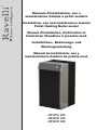 1
1
-
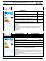 2
2
-
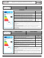 3
3
-
 4
4
-
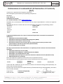 5
5
-
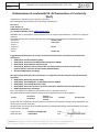 6
6
-
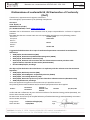 7
7
-
 8
8
-
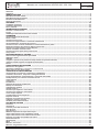 9
9
-
 10
10
-
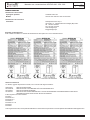 11
11
-
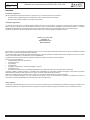 12
12
-
 13
13
-
 14
14
-
 15
15
-
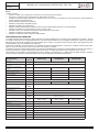 16
16
-
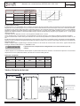 17
17
-
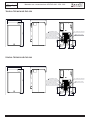 18
18
-
 19
19
-
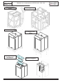 20
20
-
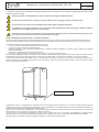 21
21
-
 22
22
-
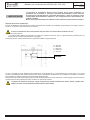 23
23
-
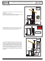 24
24
-
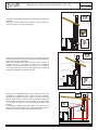 25
25
-
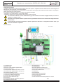 26
26
-
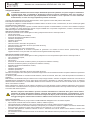 27
27
-
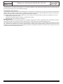 28
28
-
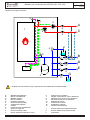 29
29
-
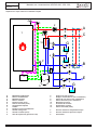 30
30
-
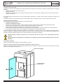 31
31
-
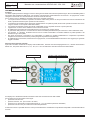 32
32
-
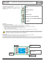 33
33
-
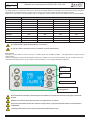 34
34
-
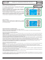 35
35
-
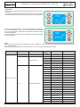 36
36
-
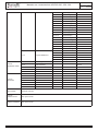 37
37
-
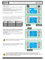 38
38
-
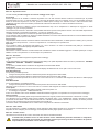 39
39
-
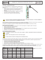 40
40
-
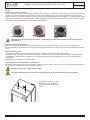 41
41
-
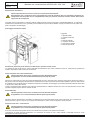 42
42
-
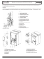 43
43
-
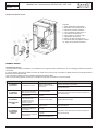 44
44
-
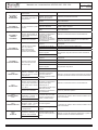 45
45
-
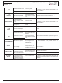 46
46
-
 47
47
-
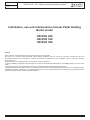 48
48
-
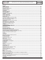 49
49
-
 50
50
-
 51
51
-
 52
52
-
 53
53
-
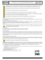 54
54
-
 55
55
-
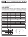 56
56
-
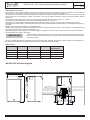 57
57
-
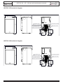 58
58
-
 59
59
-
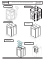 60
60
-
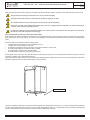 61
61
-
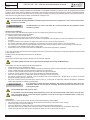 62
62
-
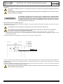 63
63
-
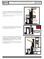 64
64
-
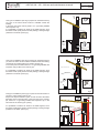 65
65
-
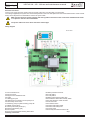 66
66
-
 67
67
-
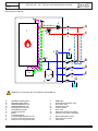 68
68
-
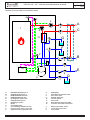 69
69
-
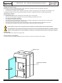 70
70
-
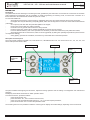 71
71
-
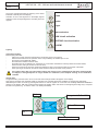 72
72
-
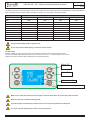 73
73
-
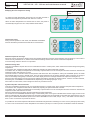 74
74
-
 75
75
-
 76
76
-
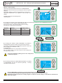 77
77
-
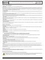 78
78
-
 79
79
-
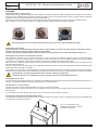 80
80
-
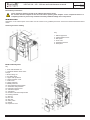 81
81
-
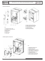 82
82
-
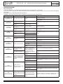 83
83
-
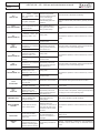 84
84
-
 85
85
-
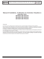 86
86
-
 87
87
-
 88
88
-
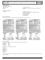 89
89
-
 90
90
-
 91
91
-
 92
92
-
 93
93
-
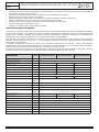 94
94
-
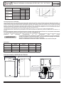 95
95
-
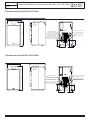 96
96
-
 97
97
-
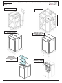 98
98
-
 99
99
-
 100
100
-
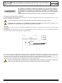 101
101
-
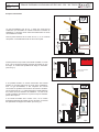 102
102
-
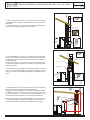 103
103
-
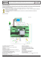 104
104
-
 105
105
-
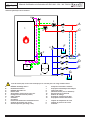 106
106
-
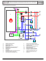 107
107
-
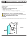 108
108
-
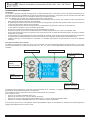 109
109
-
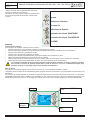 110
110
-
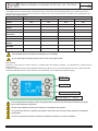 111
111
-
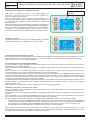 112
112
-
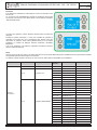 113
113
-
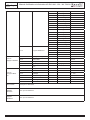 114
114
-
 115
115
-
 116
116
-
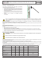 117
117
-
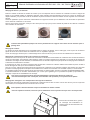 118
118
-
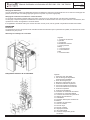 119
119
-
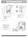 120
120
-
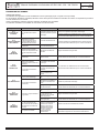 121
121
-
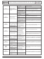 122
122
-
 123
123
-
 124
124
-
 125
125
-
 126
126
-
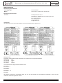 127
127
-
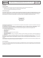 128
128
-
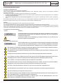 129
129
-
 130
130
-
 131
131
-
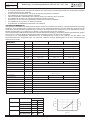 132
132
-
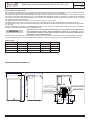 133
133
-
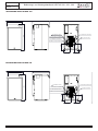 134
134
-
 135
135
-
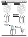 136
136
-
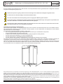 137
137
-
 138
138
-
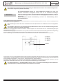 139
139
-
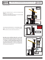 140
140
-
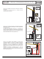 141
141
-
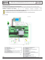 142
142
-
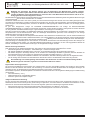 143
143
-
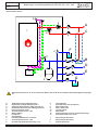 144
144
-
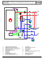 145
145
-
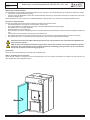 146
146
-
 147
147
-
 148
148
-
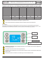 149
149
-
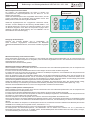 150
150
-
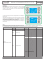 151
151
-
 152
152
-
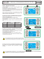 153
153
-
 154
154
-
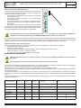 155
155
-
 156
156
-
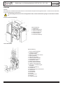 157
157
-
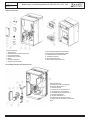 158
158
-
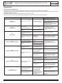 159
159
-
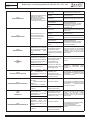 160
160
-
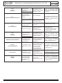 161
161
-
 162
162
-
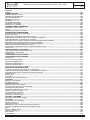 163
163
-
 164
164
-
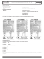 165
165
-
 166
166
-
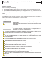 167
167
-
 168
168
-
 169
169
-
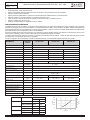 170
170
-
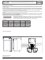 171
171
-
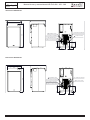 172
172
-
 173
173
-
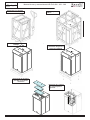 174
174
-
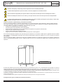 175
175
-
 176
176
-
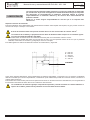 177
177
-
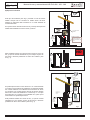 178
178
-
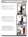 179
179
-
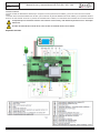 180
180
-
 181
181
-
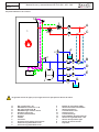 182
182
-
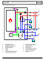 183
183
-
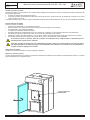 184
184
-
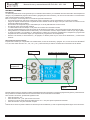 185
185
-
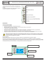 186
186
-
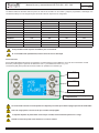 187
187
-
 188
188
-
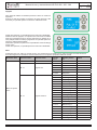 189
189
-
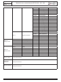 190
190
-
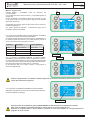 191
191
-
 192
192
-
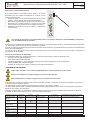 193
193
-
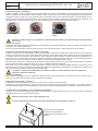 194
194
-
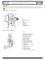 195
195
-
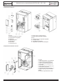 196
196
-
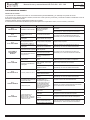 197
197
-
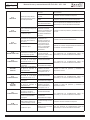 198
198
-
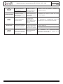 199
199
-
 200
200


Ravelli HR EVO 290 Installation, Use And Maintenance Manual
- Tipo
- Installation, Use And Maintenance Manual
- Este manual también es adecuado para
En otros idiomas
- français: Ravelli HR EVO 290
- italiano: Ravelli HR EVO 290
- English: Ravelli HR EVO 290
- Deutsch: Ravelli HR EVO 290
Documentos relacionados
-
Ravelli HR EVØ 350 Smart Use and Maintenance Manual
-
-
-
-
-
-
-
-
-