Bernard 600 Amp Manual de usuario
- Categoría
- Sistema de soldadura
- Tipo
- Manual de usuario

Issued Feb 2022 • Index No. WCMAN-1.5
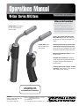
Operations Manual
W-Gun™ Series MIG Guns
All Guns are Not Created Equal.
A MIG gun should be durable, easy to
use and customized to your specific
application. Our MIG guns put you in
control: you choose the options you need
and we'll build a gun to last. We even
ship most of our guns within 24 hours.
See Tregaskiss.com
for detailed specs and
replacement parts information.
Flexible cable assembly with reinforced syn-
thetic rubber hoses prevents water leakage and
provides increased water flow and reduced gas
leakage.
Newly designed back end and water block with
interchangeable direct plugs and trigger leads
connect to wire feeders and machines from major
manufacturers and allow for simple maintenance.
Multiple handle and trigger options to increase
operator comfort.
Heavy duty water-cooled necks are offered in
multiple length and bend configurations to allow
for optimal weld accessibility and improved
operator comfort.
Contact tip options include CenterfireTM, Elliptical
and Quik TipTM and are available in wire sizes from
.023" (0.6 mm) to 3/32" (2.4 mm).
600 Amp W-Gun shown
with curved handle and
hang up hook.
600 Amp W-Gun shown with one
piece HD straight handle with
rubber overmold.
Bernard
A Division of Miller Electric Mfg. LLC
449 West Corning Road
Beecher, Illinois 60401 USA
Phone: 1-855-MIGWELD (644-9353) (US & Canada)
+1-519-737-3030 (International)
Fax: 708-946-6726
For more information, visit us at Tregaskiss.com

Protect yourself and others from injury – read, follow,
and save these important safety precautions and
operating instructions.
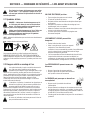
1-1 Symbol Usage
DANGER! – Indicates a hazardous situation which, if
not avoided, will result in death or serious injury. The
possible hazards are shown in the adjoining symbols
or explained in the text.
Indicates a hazardous situation which, if not avoided,
could result in death or serious injury. The possible
hazards are shown in the adjoining symbols or
explained in the text.
NOTICE–Indicatesstatementsnotrelatedtopersonalinjury.
– Indicatesspecialinstructions.
ThisgroupofsymbolsmeansWarning!WatchOut!
ELECTRICSHOCK,MOVINGPARTS,andHOTPARTShazards.
Consultsymbolsandrelatedinstructionsbelowfornecessary
actionstoavoidthehazards.
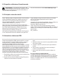
1-2 Arc Welding Hazards
Thesymbolsshownbelowareusedthroughoutthis
manualtocallattentiontoandidentifypossiblehazards.
Whenyouseethesymbol,watchout,andfollowthe
relatedinstructionstoavoidthehazard.Thesafetyinformation
givenbelowisonlyasummaryofthemorecompletesafety
informationfoundinsection1-4PrincipalSafetyStandardson
page3,andinweldingpowersourceOwner'sManual.Readand
followallSafetyStandards.
Onlyqualifiedpersonsshouldinstall,operate,maintain,
andrepairthisequipment.Aqualifiedpersonisdefined
asonewho,bypossessionofarecognizeddegree,
certificate,orprofessionalstanding,orwhobyextensive
knowledge,trainingandexperience,hassuccessfully
demonstratedabilitytosolveorresolveproblemsrelatingtothe
subjectmatter,thework,ortheprojectandhasreceivedsafety
trainingtorecognizeandavoidthehazardsinvolved.
Duringoperation,keepeverybody,especiallychildren,
away.
ELECTRIC SHOCK can kill.
lAlwaysweardryinsulatinggloves.
lInsulateyourselffromworkandground.
lDonottouchliveelectrodeorelectricalparts.
lReplaceworn,damaged,orcrackedgunsorcables.
lTurnoffweldingpowersourcebeforechangingcontacttipor
gunparts.
lKeepallcoversandhandlesecurelyinplace.
FUMES AND GASES can be hazardous.
lKeepyourheadoutofthefumes.
lVentilatearea,orusebreathingdevice.The
recommendedwaytodetermineadequate
ventilationistosampleforthecomposition
andquantityoffumesandgasestowhichpersonnelare
exposed.
lReadandunderstandtheSafetyDataSheets(SDSs)andthe
manufacturer’sinstructionsforadhesives,coatings,cleaners,
consumables,coolants,degreasers,fluxes,andmetals.
MOVING PARTS can injure.
lKeepawayfrommovingparts.
lKeepawayfrompinchpointssuchasdrive
rolls.
WELDING can cause fire or explosion.
lDonotweldnearflammablematerial.
lDonotweldoncontainersthathaveheld
combustibles,oronclosedcontainerssuchas
tanks,drums,orpipesunlesstheyare
properlypreparedaccordingtoAWSF4.1andAWSA6.0(see
SafetyStandards).
lWatchforfire;keepextinguishernearby.
lReadandunderstandtheSafetyDataSheets(SDSs)andthe
manufacturer’sinstructionsforadhesives,coatings,cleaners,
consumables,coolants,degreasers,fluxes,andmetals.
BUILDUP OF GAS can injure or kill.
lShutoffcompressedgassupplywhennotin
use.
lAlwaysventilateconfinedspacesoruseapprovedair-
suppliedrespirator.
ARC RAYS can burn eyes and skin.
Arcraysfromtheweldingprocessproduceintense
visibleandinvisible(ultravioletandinfrared)rays
thatcanburneyesandskin.Sparksflyofffromthe
weld.
1
SECTION 1 — SAFETY PRECAUTIONS — READ BEFORE USING

lWearanapprovedweldinghelmetfittedwithapropershade
offilterlensestoprotectyourfaceandeyesfromarcraysand
sparkswhenweldingorwatching(seeANSIZ49.1andZ87.1
listedinSafetyStandards).
lWearapprovedsafetyglasseswithsideshieldsunderyour
helmet.
lUseprotectivescreensorbarrierstoprotectothersfrom
flash,glareandsparks;warnothersnottowatchthearc.
lWearbodyprotectionmadefromleatherorflame-resistant
clothing(FRC).Bodyprotectionincludesoil-freeclothing
suchasleathergloves,heavyshirt,cufflesstrousers,high
shoes,andacap.
HOT PARTS can burn.
lAllowguntocoolbeforetouching.
lDonottouchhotmetal.
lProtecthotmetalfromcontactbyothers.
NOISE can damage hearing.
Noisefromsomeprocessesor
equipmentcandamagehearing.
lCheckfornoiselevellimits
exceedingthosespecifiedby
OSHA.
lUseapprovedearplugsorearmuffsifnoiselevelishigh.
lWarnothersnearbyaboutnoisehazard.
WELDING WIRE can injure.
lKeephandsandbodyawayfromguntipwhen
triggerispressed.
READ INSTRUCTIONS.
lReadandfollowalllabelsandtheOwner's
Manualcarefullybeforeinstalling,operating,
orservicingunit.Readthesafetyinformation
atthebeginningoftheManualandineachsection.
lUseonlygenuinereplacementpartsfromthemanufacturer.
lPerforminstallation,maintenance,andserviceaccordingto
theOwner'sManuals,industrystandards,andnational,state,
andlocalcodes.
2

1-3 California Proposition 65 Warnings
WARNING:Thisproductcanexposeyoutochemicals
includinglead,whichareknowntothestateofCaliforniato
causecancerandbirthdefectsorotherreproductiveharm.
Formoreinformation,gotowww.P65Warnings.ca.gov.
1-4 Principal Safety Standards
Safety in Welding, Cutting, and Allied Processes,AmericanWelding
SocietystandardANSIStandardZ49.1.Website:www.aws.org.
Safe Practice For Occupational And Educational Eye And Face
Protection,ANSIStandardZ87.1,fromAmericanNational
StandardsInstitute.Website:www.ansi.org.
Safe Practices for the Preparation of Containers and Piping for
Welding and Cutting,AmericanWeldingSocietyStandardAWS
F4.1.Website:www.aws.org.
National Electrical Code,NFPAStandard70fromNationalFire
ProtectionAssociation.Website:www.nfpa.org.
Safe Handling of Compressed Gases in Cylinders,CGAPamphletP-
1fromCompressedGasAssociation.Website:www.cganet.com.
Safety in Welding, Cutting, and Allied Processes,CSAStandard
W117.2fromCanadianStandardsAssociation.Website:
www.csagroup.org.
Standard for Fire Prevention During Welding, Cutting, and Other
Hot Work,NFPAStandard51BfromNationalFireProtection
Association.Website:www.nfpa.org.
OSHA,OccupationalSafetyandHealthStandardsforGeneral
Industry,Title29,CodeofFederalRegulations(CFR),Part
1910.177SubpartN,Part1910SubpartQ,andPart1926,Subpart
J. Website:www.osha.gov.
SR72022-01
1-5 EMF Information
Electriccurrentflowingthroughanyconductorcauseslocalized
electricandmagneticfields(EMF).Thecurrentfromarcwelding
(andalliedprocessesincludingspotwelding,gouging,plasmaarc
cutting,andinductionheatingoperations)createsanEMFfield
aroundtheweldingcircuit.EMFfieldsmayinterferewithsome
medicalimplants,e.g.Pacemakers.Protectivemeasuresfor
personswearingmedicalimplantshavetobetaken.Forexample,
restrictaccessforpassersbyorconductindividualriskassessment
forwelders.Allweldersshouldusethefollowingproceduresin
ordertominimizeexposuretoEMFfieldsfromtheweldingcircuit:
1. Keepcablesclosetogetherbytwistingortapingthem,or
usingacablecover.
2. Donotplaceyourbodybetweenweldingcables.Arrange
cablestoonesideandawayfromtheoperator.
3. Donotcoilordrapecablesaroundyourbody.
4. Keepheadandtrunkasfarawayfromtheequipmentinthe
weldingcircuitaspossible.
5. Connectworkclamptoworkpieceasclosetotheweldas
possible.
6. Donotworknextto,sitorleanontheweldingpowersource.
7. Donotweldwhilstcarryingtheweldingpowersourcewire
feeder.
About Implanted Medical Devices:
ImplantedMedicalDevicewearersshouldconsulttheirdoctorand
thedevicemanufacturerbeforeperformingorgoingneararc
welding,spotwelding,gouging,plasmaarccutting,orinduction
heatingoperations.Ifclearedbyyourdoctor,thenfollowingthe
aboveproceduresisrecommended.
3

Pour écarter les risques de blessure pour vous-même
et pour autrui — lire, appliquer et ranger en lieu sûr
ces consignes relatives aux précautions de sécurité et
au mode opératoire.
2-1 Symboles utilisés
DANGER! – Indique une situation dangereuse qui si
on l’évite pas peut donner la mort ou des blessures
graves. Les dangers possibles sont montrés par les
symboles joints ou sont expliqués dans le texte.
Indique une situation dangereuse qui si on l’évite pas
peutdonner la mort ou des blessures graves. Les
dangers possiblessont montrés par les symboles
joints ou sont expliquésdans le texte.
AVIS – Indique des déclarations pas en relation avec des blessures
personnelles.
–Indique des instructions spécifiques.
CegroupedesymbolesveutdireAvertissement!Attention!
DANGERDECHOCELECTRIQUE,PIECESENMOUVEMENT,et
PIECESCHAUDES.Reportez-vousauxsymbolesetauxdirectives
cidessousafindeconnaîtrelesmesuresàprendrepourévitertout
danger.
2-2 Dangers relatifs au soudage à l'arc
Lessymbolesdonnésci-aprèssontutilisésdanstoutle
ma-nuelpourattirerl’attentionsurlesdangers
possiblesetpourindiquerletypededangerdontils’agit.
Quandonvoitlesymbole,prendregardeetsuivrelesdirectives
corres-pondantespouréviterledanger.Lesconsignesdesécurité
présentéesci-aprèsnefontquerésumerl’informationcontenue
danslesNormesdesécuritéprincipales,etdansleGuide
d’utilisationdelasourcedecourantdesoudage.Lireetsuivre
touteslesNormesdesécurité.
L'installation,l'utilisation,l'entretienetlesréparationsne
doiventêtreconfiésqu'àdespersonnesqualifiées.Une
personnequalifiéeestdéfiniecommecellequi,parla
possessiond'undiplômereconnu,d'uncertificatoud'unstatut
professionnel,ouqui,paruneconnaissance,uneformationetune
expérienceapprofondies,adémontréavecsuccèssacapacitéà
résoudrelesproblèmesliésàlatâche,letravailouleprojeteta
reçuuneformationensécuritéafindereconnaîtreetd'éviterles
risquesinhérents.
Aucoursdel'utilisation,tenirtoutepersonneàl'écartet
plusparticulièrementlesenfants.
UN CHOC ÉLECTRIQUE peut tuer.
lPortertoujoursdesgantssecsetisolants.
lS’isolerdelapièceetdelaterre.
lNejamaistoucheruneélectrodeoudespiècesélectriques
soustension.
lRemplacerlespistoletsoucâblesdesoudagequisont
endommagés,usésoucraquelés.
lMettrelasoudeusehorstensionavantderemplacerunbec
contactoudespiècesdepistolet.
lS’assurerquetouslescouverclesetpoignéessont
fermementassujettis.
LES FUMÉES ET LES GAZ peuvent être
dangereux.
lGarderlatêtehorsdesfumées.
lAérerlazonedetravailouporterunappareil
respiratoire.Pourdéterminerlabonne
ventilation,ilestrecommandédeprocéderàunprélèvement
pourlacompositionetlaquantitédefuméesetdegaz
auxquelsestexposélepersonnel.
lLireetcomprendrelesfichesdedonnéesdesécuritéetles
instructionsdufabricantconcernantlesadhésifs,les
revêtements,lesnettoyants,lesconsommables,lesproduits
derefroidissement,lesdégraisseurs,lesfluxetlesmétaux.
Les PIÈCES MOBILES peuvent causer des
blessures.
lNepass’approcherdesorganesmobiles.
lNepass’approcherdespointsdecoincement
telsquedesrouleauxdecommande.
Le SOUDAGE peut provoquer un incendie ou
une explosion.
lNepassouderàproximitédematériaux
inflammables
lNepaseffectuerlesoudagesurdesconteneursferméstels
quedesréservoirs,tambours,ouconduites,àmoinsqu’ils
n’aientétépréparéscorrectementconformémentàAWSF4.1
etAWSA6.0(voirlesNormesdeSécurité).
lPrendregardeauxincendiesettoujoursavoirunextincteurà
proximité.
SECTION 2 — CONSIGNES DE SÉCURITÉ — LIRE AVANT UTILISATION
4

lLireetcomprendrelesfichesdedonnéesdesécuritéetles
instructionsdufabricantconcernantlesadhésifs,les
revêtements,lesnettoyants,lesconsommables,lesproduits
derefroidissement,lesdégraisseurs,lesfluxetlesmétaux.
L'ACCUMULATION DE GAZ risquent de
provoquer des blessures ou même la mort.
lFermerl’alimentationdugazcompriméencas
denonutilisation.
lVeillertoujoursàbienaérerlesespacesconfinésouseservir
d’unrespirateurd’adductiond’airhomologué.
LE RAYONNEMENT DE L'ARC peut brûler les
yeux et la peau.
Lerayonnementdel’arcduprocédédesoudage
génèredesrayonsvisiblesetinvisiblesintenses
(ultravioletsetinfrarouges)susceptiblesde
provoquerdesbrûluresdanslesyeuxetsurlapeau.Desétincelles
sontprojetéespendantlesoudage.
lPorteruncasquedesoudageapprouvémunideverres
filtrantsappropriépourprotégervisageetyeuxpendantle
soudage(voirANSIZ49.1etZ87.1énumérédanslesnormes
desécurité).
lPorterdeslunettesdesécuritéavecécranslatérauxmême
sousvotrecasque.
lAvoirrecoursàdesécransprotecteursouàdesrideauxpour
protégerlesautrescontrelesrayonnementsles
éblouissementsetlesétincelles;prévenirtoutepersonnesur
leslieuxdenepasregarderl’arc.
lPorteruneprotectioncorporelleencuiroudesvêtements
ignifu-ges(FRC).Laprotectionducorpscomportedes
vêtementssanshuile,commedesgantsdecuir,unechemise
solide,despanta-lonssansrevers,deschaussureshauteset
unecasquette.
LES PIÈCES CHAUDES peuvent provoquer
des brûlures.
lLaisserrefroidirlepistoletavantdeletoucher.
lNepastoucherd’objetsmétalliqueschauds.
lAbriterlesobjetsmétalliquescontretoutcontactparles
personnesàproximité.
Le BRUIT peut endommager l’ouie.
Lebruitdesprocessusetdeséquipementspeut
affecterl’ouïe.
lVérifiersilesniveauxdebruitexcèdentles
limitesspécifiéesparl’OSHA.
lUtiliserdesbouche-oreillesoudesserre-têteantibruit
approuvéssileniveaudebruitestélevé.
lAvertirlespersonnesàproximitéausujetdudangerinhérent
aubruit.
.
LES FILS DE SOUDAGE peuvent provoquer
des blessures.
lÉloignerlesmainsetlecorpsdelabusedu
pistoletaprèsavoirappuyésurlagâchette.
LIRE LES INSTRUCTIONS.
lLireetappliquerlesinstructionssurles
étiquettesetleModed’emploiavant
l’installation,l’utilisationoul’entretiende
l’appareil.Lirelesinformationsdesécuritéaudébutdu
manueletdanschaquesection.
lN’utiliserquelespiècesderemplacementprovenantdu
fabricant.
lEffectuerl’installation,l’entretienettouteinterventionselon
lesmanuelsd’utilisateurs,lesnormesnationales,provinciales
etdel’industrie,ainsiquelescodesmunicipaux.
5

2-3 Proposition californienne 65 avertissements
AVERTISSEMENT–Ceproduitpeutvousexposeràdes
produitschimiquestelsqueleplomb,reconnusparl’Étatde
Californiecommecancérigènesetsourcesdemalformationsou
d’autrestroublesdelareproduction
Pourplusd’informations,consulterwww.P65Warnings.ca.gov.
2-4 Principales normes de sécurité
Safety in Welding, Cutting, and Allied Processes,AmericanWelding
SocietystandardANSIStandardZ49.1.Website:www.aws.org.
Safe Practice For Occupational And Educational Eye And Face
Protection,ANSIStandardZ87.1,fromAmericanNational
StandardsInstitute.Website:www.ansi.org.
Safe Practices for the Preparation of Containers and Piping for
Welding and Cutting,AmericanWeldingSocietyStandardAWSF4.1
fromGlobalEngineeringDocuments.Website:www.aws.org.
National Electrical Code,NFPAStandard70fromNationalFire
ProtectionAssociation.Website:www.nfpa.org.
Safe Handling of Compressed Gases in Cylinders,CGAPamphletP-
1fromCompressedGasAssociation.Website:www.cganet.com.
Safety in Welding, Cutting, and Allied Processes,CSAStandard
W117.2fromCanadianStandardsAssociation.Website:
www.csagroup.org.
Standard for Fire Prevention During Welding, Cutting, and Other Hot
Work,NFPAStandard51BfromNationalFireProtection
Association.Website:www.nfpa.org.
OSHA,OccupationalSafetyandHealthStandardsforGeneral
Industry,Title29,CodeofFederalRegulations(CFR),Part1910.177
SubpartN,Part1910SubpartQ,andPart1926,SubpartJ.Website:
www.osha.gov.
SR7_fre2022-01
2-5 Informations relatives aux CEM
Lecourantélectriquequitraversetoutconducteurgénèredes
champsélectromagnétiques(CEM)àcertainsendroits.Lecourant
issud’unsoudageàl’arc(etdeprocédésconnexes,ycomprisle
soudageparpoints,legougeage,ledécoupageplasmaetles
opérationsdechauffageparinduction)créeunchamp
électromagnétique(CEM)autourducircuitdesoudage.Leschamps
électromagnétiquesproduitspeuventcauserinterférenceàcertains
implantsmédicaux,p.ex.lesstimulateurscardiaques.Desmesures
deprotectionpourlesporteursd’implantsmédicauxdoiventêtre
prises:parexemple,desrestrictionsd’accèspourlespassantsou
uneévaluationindividuelledesrisquespourlessoudeurs.Tousles
soudeursdoiventappliquerlesprocéduressuivantespour
minimiserl’expositionauxCEMprovenantducircuitdesoudage:
1. Rassemblerlescâblesenlestorsadantouenlesattachantavec
durubanadhésifouavecunehousse.
2. Nepasseteniraumilieudescâblesdesoudage.Disposerles
câblesd’uncôtéetàdistancedel’opérateur.
3. Nepascourberetnepasentourerlescâblesautourdevotre
corps.
4. Maintenirlatêteetletorseaussiloinquepossibledumatériel
ducircuitdesoudage.
5. Connecterlapincesurlapièceaussiprèsquepossibledela
soudure.
6. Nepastravailleràproximitéd’unesourcedesoudage,ni
s’asseoirousepencherdessus.
7. Nepassoudertoutenportantlasourcedesoudageoule
dévidoir.
En ce qui concerne les implants médicaux :
Lesporteursd’implantsdoiventd’abordconsulterleurmédecin
avantdes’approcherdesopérationsdesoudageàl’arc,desoudage
parpoints,degougeage,ducoupageplasmaoudechauffagepar
induction.Silemédecinapprouve,ilestrecommandédesuivreles
procéduresprécédentes.
6

Protéjase usted mismo y a otros contra lesiones —
lea, cumpla y conserve estas importantes
precauciones de seguridad e instrucciones de
utilización.
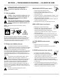
3-1 Uso de símbolos
PELIGRO! – Indica una situación peligrosa que, si no
se la evita, resultará en muerte o lesión grave. Los
peligros posibles se muestran en los símbolos
adjuntos o se explican en el texto.
Indica una situación peligrosa que, si no se la evita,
podríaresultar en muerte o lesión grave. Los peligros
posiblesse muestran en los símbolos adjuntos, o se
explican en eltexto.
AVISO – Indica precauciones no relacionadas a lesiones
personales.
–Indica instrucciones especiales.
Estegrupodesímbolossignifica¡Advertencia!,¡Cuidado!
CHOQUEODESCARGAELÉCTRICA,PIEZASQUESEMUEVEN,y
peligrosdePARTESCALIENTES.Consultelossímbolosylas
instruccionesrelacionadasqueaparecenacontinuaciónparaver
lasaccionesnecesariasparaevitarestospeligros.
3-2 Peligros en soldadura de arco
Lossímbolosmostradosabajoseusanentodoeste
manualparallamarlaatenciónaeidentificarlosposibles
peligros.Cuandoveaelsímbolo,presteatenciónysiga
lasinstruc-cionesrelacionadasparaevitarelpeligro.La
informacióndeseguridaddadaabajoessolamenteunresumende
lain-formaciónmáscompletadeseguridadqueseencuentraen
losestandaresdeseguridad,ylafuentedealimentaciónpa-ra
soldaduradelManualdelusuario.Leaysigatodaslasnormasde
seguridad.
Solamentepersonalcualificadodebeinstalar,utilizar,
manteneryrepararesteequipo.Ladefiniciónde
personalcualificadoescualquierpersonaque,debidoa
queposeeuntítulo,uncertificadoounaposiciónprofesional
reconocida,ograciasasugranconocimiento,capacitacióny
experiencia,hayademostradoconéxitolacapacidadpara
solucionaroresolverproblemasrelacionadosconeltrabajo,el
proyectooeltemaencuestión,ademásdehaberasistidoauna
capacitaciónenseguridadparareconoceryevitarlospeligrosque
implicaelproceso.
Durantesuoperaciónmantengalejosatodos,
especialmentealosniños.
UNA DESCARGA ELÉCTRICA puede matarlo.
lSiempreuseguantesaislantessecos.
lAísleseustedmismodeltrabajoylatierra.
lNotoqueelectrodoeléctricamentevivoopartes
eléctricamentevivas.
lReemplaceantorchasocablesdesgastados,dañadosorotos.
lRepareoreemplaceaislamientodelapistolaodelcableque
estédesgastado,dañadooagrietado.
lApaguelamáquinadesoldarantesdecambiarlostubosde
contactoopiezasdelaantorcha.
lMantengatodaslastapasyasabiensegurasensitio.
HUMO y GASES pueden ser peligrosos.
lMantengasucabezafueradelhumo.
lVentileellugarouseunaparatopararespirar.
Elmétodorecomendadoparadeterminarla
ventilaciónadecuadaestomarmuestrasdela
composiciónycantidaddehumosygasesalosqueestá
expuestoelpersonal.
lLeayentiendalasHojasdedatosdelmaterial(SDS)ylas
instruccionesdelfabricanterelacionadasconlosadhesivos,
metales,consumibles,recubrimientos,limpiadores,
refrigerantes,desengrasadores,fundentesymetales.
Las PIEZAS MÓVILES pueden provocar
lesiones.
lAléjesedetodaparteenmovimiento.
lAléjesedetodopuntoquepellizque,talcomorodillos
impulsados.
EL SOLDAR puede causar fuego o explosión.
lNosueldecercadematerialinflamable
lNosueldeenrecipientesquehancontenido
combustibles,nienrecipientescerradoscomo
tanques,tamboresotuberías,amenosque
esténpreparadoscorrectamentedeacuerdoconlanorma
AWSF4.1yAWSA6.0(vealasnormasdeseguridad).
lSiempremirequenohayafuegoymantengaunextinguidor
defuegocerca.
lLeayentiendalasHojasdedatosdelmaterial(SDS)ylas
instruccionesdelfabricanterelacionadasconlosadhesivos,
metales,consumibles,recubrimientos,limpiadores,
refrigerantes,desengrasadores,fundentesymetales.
7
SECTION 3 — PRECAUCIONES DE SEGURIDAD — LEA ANTES DE USAR

EL AMONTONAMIENTO DE GAS puede
enfermarle o matarle.
lCierreelsuministrodegascomprimido
cuandonolouse.
lSiempredéventilaciónaespacioscerradosouseun
respiradoraprobadoquereemplazaelaire.
LOS RAYOS DEL ARCO pueden quemar sus
ojos y piel.
Losrayosdelarcodeunprocesodesuelda
producenuncalorintensoyrayosultravioletas
fuertesquepuedenquemarlosojosylapiel.Las
chispasseescapandelasoldadura.
lUseunacaretaparasoldaraprobadaequipadaconunfiltrode
protecciónapropiadoparaprotegersucarayojosdelos
rayosdelarcoydelaschispasmientrasestésoldandoo
mirando.(véaselosestándaresdeseguridadANSIZ49.1y
Z87.1).
lUseanteojosdeseguridadaprobadosquetenganprotección
lateral.
lUsepantallasdeprotecciónobarrerasparaprotegeraotros
deldestello,reflejosychispas,alerteaotrosquenomirenel
arco.
lUseprotecciónparaelcuerpohechadecueroodeprendas
resis-tentesalasllamas(FRC).Entrelaprotecciónparael
cuerposein-cluyelaropasinaceite,comoguantesdecuero,
unacamisagruesa,pantalonessinvuelta,calzadoaltoyuna
gorra.
PARTES CALIENTES puedan causar
quemaduras severas.
lPermitaquelaantorchaseenfríeantesde
tocarla.
lNotoquemetalcaliente.
lProtejaaotrosdelcontactoconelmetalcaliente.
EL RUIDO puede trastornar su oído.
Ruidoprovenientedealgunosprocesosoequipo
puededañareloído.
lChequeeloslímitesdelniveldelruidosi
excedenaquellosespecificadosporOSHA.
lUsetapasparalosoídosocubiertasparalosoídossielnivel
delruidoesdemasiadoalto.
lAdviertaaotrosqueesténcercaacercadelpeligrodelruido.
El ALAMBRE de SOLDAR puede causarle
heridas.
lMantengalasmanosyelcuerpolejosdeltubo
decontactodelaantorchacuandosehaya
presionadoelgatillo.
LEER INSTRUCCIONES.
lLeaysigacuidadosamentelasinstrucciones
contenidasentodaslasetiquetasyenel
Manualdelusuarioantesdeinstalar,utilizaro
realizartareasdemantenimientoenlaunidad.Leala
informacióndeseguridadincluidaenlaprimerapartedel
manualyencadasección.
lUtiliceúnicamentepiezasdereemplazolegítimasdel
fabricante.
lLostrabajosdeinstalaciónymantenimientodebenser
ejecutadosdeacuerdoconlasinstruccionesdelmanualdel
usuario,lasnormasdelsectoryloscódigosnacionales,
estatalesylocales.
8

3-3 Advertencias de la Proposición 65 del estado de California
ADVERTENCIA:Esteproductopuedeexponerloaquímicos,
inclusoplomo,queelestadodeCaliforniaconocecomo
causantesdecáncer,defectosdenacimientouotrosdaños
reproductivos.
Paraobtenermásinformación,accedaa
www.P65Warnings.ca.gov.
3-4 Estándares principales de seguridad
Safety in Welding, Cutting, and Allied Processes,AmericanWelding
SocietystandardANSIStandardZ49.1.Website:www.aws.org.
Safe Practice For Occupational And Educational Eye And Face
Protection,ANSIStandardZ87.1,fromAmericanNational
StandardsInstitute.Website:www.ansi.org.
Safe Practices for the Preparation of Containers and Piping for
Welding and Cutting,AmericanWeldingSocietyStandardAWSF4.1
fromGlobalEngineeringDocuments.Website:www.aws.org.
National Electrical Code,NFPAStandard70fromNationalFire
ProtectionAssociation.Website:www.nfpa.org.
Safe Handling of Compressed Gases in Cylinders,CGAPamphletP-
1fromCompressedGasAssociation.Website:www.cganet.com.
Safety in Welding, Cutting, and Allied Processes,CSAStandard
W117.2fromCanadianStandardsAssociation.Website:
www.csagroup.org.
Standard for Fire Prevention During Welding, Cutting, and Other
Hot Work,NFPAStandard51BfromNationalFireProtection
Association.Website:www.nfpa.org.
OSHA,OccupationalSafetyandHealthStandardsforGeneral
Industry,Title29,CodeofFederalRegulations(CFR),Part
1910.177SubpartN,Part1910SubpartQ,andPart1926,Subpart
J. Website:www.osha.gov.
SR7_spa2022–01
3-5 Información sobre los campos electromagnéticos (EMF)
Lacorrientequefluyeatravésdeunconductorgeneracampos
eléctricosymagnéticos(EMF)localizados.Lacorrientedelarcode
soldadura(yotrastécnicasafinescomolasoldaduraporpuntos,el
ranurado,elcorteporplasmayelcalentamientoporinducción)
generauncampoEMFalrededordelcircuitodesoldadura.Los
camposEMFpuedeninterferirconalgunosdispositivosmédicos
implantadoscomo,porejemplo,losmarcapasos.Porlotanto,se
debentomarmedidasdeprotecciónparalaspersonasqueutilizan
estosimplantesmédicos.Porejemplo,apliquerestriccionesal
accesodepersonasquepasanporlascercaníasorealice
evaluacionesderiesgoindividualesparalossoldadores.Todoslos
soldadoresdebenseguirlosprocedimientosqueseindicana
continuaciónconelobjetodeminimizarlaexposiciónaloscampos
EMFgeneradosporelcircuitodesoldadura:
1. Mantengaloscablesjuntosretorciéndolosentresío
uniéndolosmediantecintasounacubiertaparacables.
2. Noubiquesucuerpoentreloscablesdesoldadura.Disponga
loscablesaunladoyapártelosdeloperario.
3. Noenrollenicuelgueloscablessobresucuerpo.
4. Mantengalacabezayeltroncotanapartadosdelequipodel
circuitodesoldaduracomoleseaposible.
5. Conectelapinzademasaenlapiezalomáscercaposibledela
soldadura.
6. Notrabajecercadelafuentedealimentaciónparasoldadura,
nisesienteorecuestesobreella.
7. Nosueldemientrastransportalafuentedealimentaciónoel
alimentadordealambre.
Acerca de los aparatos médicos implantados:
Laspersonasqueusenaparatosmédicoimplantadosdeben
consultarconsumédicoyelfabricantedelaparatoantesdellevara
cabooacercarseasoldaduradearco,soldaduradepunto,ranurar,
hacercorteporplasma,uoperacionesdecalentamientopor
inducción.Sisudoctorlopermite,entoncessigalos
procedimientosdearriba.
9

Part I General Description
The Bernard W-Gun is a water-cooled gun that is designed for
processing mild steel electrode under GMAW (Gas Metal Arc Welding),
MIG (Metal Inert Gas), MAG (Metal Active Gas), FCAW (Flux Cored Arc
Welding), and MOG (Metal without Gas).
The Bernard W-Gun provides longer consumable life while reducing
operator fatigue, which can increase overall welding effectiveness.
Bernard W-Guns can reduce the downtime and expenses associated
with changing consumables during the welding process. Lightweight
and flexible design allows for easier movement during welding between
standard horizontal welding, overhead, and hard-to-reach side angles.
Bernard W-Guns can effectively reduce your operating cost and improve
the productivity of your welding operation.
The Bernard W-Gun meets or exceeds NEMA (National Electrical
Manufacturer’s Association) EW3 and CE EN50078 requirements for
guns used in a wide variety of applications including aluminum, silicone
bronze, and hard facing alloys to name a few. With Bernard’s flexibility,
many applications can be accommodated with field installed options,
increasing performance and maneuverability.
Part II Installation
1. Your gun has been shipped with a specific feeder connector and
sized for electrode as per the part number indicated on its package.
Please inspect the received gun against this part number for
accuracy.
2. Turn off power prior to any installation.
3. Fully extend gun and cable. Press liner fully into power pin.
4. Safely expose approximately 2” (51 mm) of electrode beyond
feeder or adaptor block.
5a. Bernard Quick Disconnect
If you have purchased a Bernard Quick Disconnect gun, it is
necessary to connect this unit to an adaptor kit providing the
shielding gas, control circuit, and arc power. If this is a new
installation, install the adaptor kit as per the kit instructions. With
the Bernard adaptor installed, perform the following:
Orient power pin and gas pin with the adaptor receptacle. Slide
the electrode into the liner and push the power pin into the socket.
Rotate the locking sleeve until the locking pins of adaptor drop into
the receiver of locking sleeve. Continue to engage power pin while
twisting locking sleeve to make connection. Shielding gas, control
circuit, and power are now engaged.
5b. Direct Plug
Connect the power pin of the direct plug gun by sliding the
electrode into the liner and the power fitting into the drive housing
of the feeder. Fully seat the unit in position and tighten into
place as designated in the manufacturer’s instructions. On initial
installations, a thin film of silicone lubricant will aid installation and
prevent O-ring damage.
Attach control lead wires to the appropriate plug, terminals, or lead
kit. Plug or wire into the control circuit of the feeder as designated
in manufacturer’s instructions.
If a gas hose is provided, connect to the feeder’s solenoid circuit
to deliver shielding gas to the arc. If no gas hose is provided, gas
is delivered through the power pin. Refer to the manufacturer’s
instructions for proper gas connection at the feeder block or
solenoid.
6. Connect water lines to a water coolant source. Each hose is
identified for proper connection by a tethered drip cap (blue: water
inlet, red: water outlet) and label. If a water hose hook-up kit is
used, make all runs as short as possible. Always use hoses with
at least a 3/16” inside diameter for extended runs. Reinforced
hoses of high quality are recommended to prevent damage due to
operating pressures, heat, and hose contamination. The coolant
system must produce a minimum of 0.5 gpm at 60 psi. Run
coolant through gun for approximately 2 minutes to purge system
of entrapped air before applying power. Water must flow through
the gun at all times while the power supply is on.
7. Remove nozzle from gas diffuser.
8a. Centerfire Tip – Remove tip holder by turning counterclockwise
and then pull tip from gas diffuser. An unobstructed electrode path
has now been established.
8b. Elliptical Tip – Remove tip with a 1/8-1/4 turn counterclockwise
while pulling. An unobstructed electrode path has now been
established.
8c. Quik Tip – Remove tip with a 1/4 turn counterclockwise. An
unobstructed electrode path has now been established.
9. Safely feed electrode through the gun and approximately 1” (25
mm) beyond gas diffuser.
10a. Centerfire Tip – Reinstall the tip over the electrode and lock into
position by reinstalling the tip holder. Reinstall nozzle.
10b. Elliptical and Quik Tip – Reinstall the tip over the electrode locking
into position with a clockwise motion. Reinstall nozzle.
Coolant must ow through the gun prior to and
during welding. Welding current and duty cycle
should not exceed published specication of
this product. If such conditions exist, product
life and performance will be reduced.
Part III Helpful Operating Tips
Nozzles:
1. If anti-spatter is used, do not coat nozzle insulator as this may
degrade insulating material.
2. Nozzle should be cleaned as often as possible. Spatter buildup can
often lead to poor gas shielding or short circuiting between the
contact tip and the nozzle.
3. Spatter should be removed with the proper tools designed for
spatter removal.
4. In high temperature welding applications, heavy duty consumables
are recommended.
Contact Tips, Gas Diffusers:
1. Centerfire and Elliptical contact tips may be removed and rotated in
gas diffuser, providing additional wear surfaces and extending the
service life of the product.
2. Electrical stickout of the elliptical contact tip can be altered by
positioning the contact tip in the desired location of the gas
diffuser and rotating clockwise locking in place.
3. Inspect nozzle for spatter adhesion, blocked gas ports, and carbon-
ized contact surfaces. Clean as often as possible.
4. If anti-spatter is used, periodically check gas ports for blockage.
5. When using dual shield electrode, periodically check gas ports for
clogging caused by flux from within the electrode.
10

Cable:
1. Periodically check torques of neck and end fittings. Loose fittings
can cause overheating and premature failure of the gun.
2. Sharp bends and loops in the cable should be avoided. Often the
best solution is to suspend the wire feeder from a boom or trolley,
thus eliminating a large number of bends and keeping the cable
clear of hot weldments.
3. Do not immerse liner into solvents for cleaning; the liner may be
periodically blown out with compressed air.
4. Avoid rough surfaces and sharp edges that can cause tears and
nicks in cable jacket which can cause premature failure.
5. Periodically check all cables and ground connections.
6. Use anti-seize on all threaded connections.
Feeder:
1. Check drive rolls for wear; be sure drive rolls and guide tubes are
clean and free of debris. Do not overtighten drive rolls; set as per
manufacturer’s specifications.
2. Use clean, non-corroded electrode.
3. When installing or replacing electrode, you may: remove burrs
from end of electrode, remove gas diffuser and tip, and/or
straighten the first few inches of electrode.
End User Stocking Recommendations:
Nozzles ...................................... 5 for every 1 gun in service
Tips ........................................... 30 for every 1 gun in service
Gas Diffusers ............................ 4 for every 1 gun in service
Triggers ..................................... 1 for every 10 guns in service
Necks ........................................ 1 for every 20 guns in service
Handle Kits ................................ 1 for every 20 guns in service
Replacement Cables .................. 1 for every 20 guns in service
Strain Relief Kits ....................... 1 for every 20 guns in service
Adaptor Kits .............................. Order as Necessary
Direct Plug Kits ......................... Order as Necessary
These stocking recommendations are only initial guidelines based on
an 80 hour work period. You should work closely with your distributor
to tailor a stocking program that suits your specific needs. Results will
vary.
Part IV Maintenance and
Repair
See Replacement Parts page of www.BernardWelds.com for complete
parts lists and specs
Disconnect gun from equipment, allow gun
to cool, and remove electrode from liner
before servicing.
Section 1. General Inspection
1. Inspect gun periodically for worn or loose parts. Tighten, repair, or
replace as necessary.
2. Periodically inspect outer cable cover for nicks or cuts that can
cause short circuiting or allow the cable assembly’s internal
components to become exposed. Replace as necessary.
3. Inspect adapter and direct plug connection for wear that may cause
overheating. Replace as necessary.
4. Change or rotate contact tip when arc tracking or arc instability is
incurred. Please note; a tip may look worn but produce a stable arc
with good results.
5. Clean the nozzle as often as possible to prevent spatter build-up.
Excess spatter can lead to poor gas shielding or short circuiting.
Replace the nozzle when worn.
6. Periodically check torques of all water connections to maintain
cool and dry operation. Tighten as described in the following
sections.
7. Replace liner system as electrode feeding becomes erratic.
Section 2. Nozzle
A. Removal
The nozzle is a friction fit which can be removed with a twisting and
pulling motion.
B. Service
Inspect nozzle for cracks and degradation of insulation. Clean the nozzle
as often as possible to prevent spatter build-up which can lead to poor
gas shielding or short circuiting. Replace the nozzle when loose, worn,
or producing erratic gas shielding.
C. Installation
Replace with a pushing and twisting motion.
Section 3. Contact Tip
Bernard has designed its contact tips to allow rapid installation and
adjustment.
A. Removal
Cut electrode and remove all burrs before removing tip.
Centerfire Tip – Remove tip holder by turning counterclockwise and then
pull tip from gas diffuser.
Elliptical Tip – Remove tip with 1/8-1/4 turn counterclockwise.
Quik Tip – Remove tip with a 1/4 turn counterclockwise.
B. Service
To extend contact tip life, reface front of tip and clean the bore.
Centerfire and Elliptical tips may be rotated in gas diffuser socket
providing additional wear surface and extending the service life of the
product. Electrical stickout may be altered when using Elliptical tips by
positioning the contact tip in the desired location of the gas diffuser
before locking into place.
C. Installation
Centerfire Tip - Reinstall the tip over the electrode and lock into position
by reinstalling the tip holder. Reinstall nozzle.
Elliptical and Quik Tip – Reinstall the tip over the electrode locking into
position with a clockwise motion. Reinstall nozzle.
Section 4. Gas Diffuser
A. Removal
The gas diffuser may be removed with an appropriate wrench in a
counterclockwise rotation.
B. Service
Inspect gas diffuser and Centerfire tip holder for spatter, blocked gas
ports, and carburized surfaces. Clean as often as possible. Replace
with new gas diffuser or Centerfire tip holder when wear prevents
engagement of contact tip or nozzle.
11

C. Installation
Firmly secure gas diffuser with an appropriate wrench in a clockwise
rotation. Always reinstall gas diffuser insulator to decrease the chances
of short circuiting. Note that Centerfire gas diffuser does not require a
gas diffuser insulator.
Section 5. Liner
A. Removal
Remove nozzle, contact tip, and gas diffuser. Lay cable straight. Grasp
liner lock which protrudes from power pin (some direct plugs may
require removal of additional components to access the liner lock) and
remove from cable assembly by pulling.
B. Service
Inspect for excessive wear and debris on the inside diameter. Do not dip
liner in solvents for cleaning. Liner may be periodically blown out with
compressed air. Replace with new liner when excessive wear or debris
produces poor electrode feed.
C. Installation
Insert liner into power pin with cable laying straight. Continue until liner
lock is fully seated into power pin. A twisting motion may be necessary
to seat o-ring (some direct plugs may require installation of additional
components to secure liner). Trim and deburr the liner 3/8” (9.5 mm)
past the nozzle end of the neck. Install gas diffuser and nozzle.
Section 6. Handle/Switch Assembly
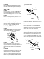
I Curved Handle
A. Removal
Remove screws, post fasteners, and hang-up hook (See Figure 1).
Separating handle halves will expose interior connections and trigger
switch assembly. Slide switch assembly out of cavity and remove
terminals from trigger.
B. Service
Inspect for cracks, deformation of hex areas, debris, holes, loose or
missing threaded inserts, excessive wear, exterior heat deformation, and
warpage. If any of the above conditions exist, replace with new handle
or clean all surfaces with mild detergent and reinstall. Test switch for
continuity. Clean any debris from trigger, if necessary, replace with new
trigger.
C. Installation
Begin assembly by placing the hexagon portion of the neck within the
rear hexagon portion of the handle half. The hex bushing will be cradled
within the forward hex locators. Install switch assembly by pressing
control wire terminals fully onto terminals of switch assembly and slide
assembly into switch cavity. Route hoses, cable, control wires, and
switch as not to be pinched when reinstalling second handle half. Install
hang-up hook, post fasteners, and handle screws. Tighten screws while
being aware not to pinch cable jacket in joint between the handle halves.
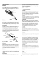
II Legacy Straight Handle
A. Removal
Remove switch and screws from handle (See Figure 2). Remove
terminals from the switch assembly. Slide handle down the cable to gain
access to neck connections. Neck must be removed to replace handle on
all round handled guns except those with straight necks.
B. Service
Inspect for cracks, debris, holes, loose or missing threaded inserts,
excessive wear, exterior heat deformation, and warpage. If any of the
above conditions exist, replace with new handle or clean all surfaces
with mild detergent and reinstall. Test switch for continuity. Clean any
debris from trigger, if necessary, replace with new trigger.
C. Installation
Slide handle over power cable. Reinstall neck (See Figure 3). Place
the hexagon bushing on the neck. Install aluminum spacers over the
bushing and secure with screws. Install insulation spacers on hexagon
water block and secure using pop rivet. Top mount switch assemblies
require insulation spacers be mounted on the bottom of the hexagon
water block. Bottom mount switch assemblies require insulation spacers
be mounted on the top of the hexagon water block. Route control wires
as not to be pinched when reinstalling handle. Align spacers and secure
with screws. Install switch assembly into position by installing terminals
onto the switch assembly and then secure with screws.
Handle Screws
Handle Half, Left
Handle Half, Right
Post Fasteners
Trigger
Hang-Up Hook
Neck
FIGURE 1
Trigger
FIGURE 2
Trigger Screws
Handle
Handle Screws
Neck
Spacer Screws
Neck
Rivet
Conduit Set Screw
Power Cable
Outer Cover
Conduit
Return Hose Spacers, Plastic
Bushing
Spacers,
Aluminum
FIGURE 3
12

III HD Straight Handle
A. Removal
Remove switch and screws from handle (See Figure 4). Cut wires
from the switch assembly to remove switch. Slide handle down the
cable to gain access to neck connections. Neck must be removed to
replace handle on all straight handled guns.
B. Service
Inspect for cracks, debris, holes, loose or missing threaded inserts,
excessive wear, exterior heat deformation, and warpage. If any of the
above conditions exist, replace with new handle or clean all surfaces
with mild detergent and reinstall. Test switch for continuity. Clean any
debris from trigger, if necessary, replace with new trigger.
C. Installation
Slide handle over power cable. Reinstall neck (See Figure 5). Locate
aluminum spacer set as shown with machined flat facing switch
assembly. Secure to neck with screws. Do not over tighten screws
to prevent neck armor from being pierced. Route control wires as
not to be pinched when reinstalling handle. Secure handle onto cable
assembly using screws. Connect switch assembly by connecting
control wires to switch with insulated butt connectors. Secure switch
assembly to handle with screw.
Section 7. Neck
A. Removal
Remove liner from cable assembly. The gas diffuser should remain
installed to protect neck threads. Remove handle from gun assembly.
Disconnect power cables and return hoses using a counterclockwise
motion with one 5/16” and one 3/8” wrench. Do not allow the power
cable and return hose fittings to twist. Using a 5/64” (2 mm) hex key,
remove conduit set screw. Remove conduit from neck.
B. Service
Inspect neck for damaged threads, leaky water connections,
excessive spatter build up on armor or armor that is damaged. If any
of the above conditions exist, replace neck to ensure safe and reliable
operation.
C. Installation
Install conduit into neck and secure with conduit set screw. See the
next section for specific conduit installation instructions. Install and
tighten power cable and return hose fittings to 35 in-lbs to prevent
leakage. Avoid twisting power cable and return hose fittings during
installation. Install handle and liner.
Section 8. Cable
I Power Cable/Return Hose
A. Removal
Remove handle, switch assembly, and open rear strain relief. Remove
outer cover ties from both ends. Disconnect power cables and return
hoses using a counterclockwise motion with one 5/16” and one 3/8”
wrench. Do not allow the power cable, return hose, or rear water block
fittings to twist which could result in breakage.
B. Service
Inspect power cable and return hose for leaks or hose material that has
been damaged. If any of the above conditions exist, replace power cable
or return hose to ensure safe and reliable operation.
C. Installation
While old cable is in place, fasten new cable to end of old cable using
the cable tool that ships with replacement cables or tape. The old cable
may now be used to pull the new through the outer cover. Install and
tighten cable to 35 in-lbs using appropriate wrenches in a clockwise
rotation to prevent leakage. Before installing handle or strain relief,
circulate coolant through unit checking for leaks; reinstall outer cover
ties on both ends and reassemble all remaining components.
II Conduit
A. Removal
Remove handle, switch assembly, liner, and open rear strain relief.
Remove outer cover ties from both ends of outer cable covering. Use a
5/64” (2 mm) hex key to remove conduit set screws and release conduit
connections (both ends).
B. Service
Inspect conduit assembly for cracks or gas leakage. If any of the above
conditions exist, replace conduit assembly to ensure reliable operation.
C. Installation
While old conduit is in place, tape or splice new conduit to end of old
conduit. The old conduit may now be used to pull the new through the
outer cover. Moisten o-rings with water or soap. Do not use silicone
or petroleum based lubricants. Slide conduit into socket on the end
of the neck. Care must be taken not to nick or cut o-ring during
installation. Look through the set screw hole to verify that the fitting has
slid completely into the neck. Secure conduit with conduit set screw.
Conduit attachment is similar at the direct plug end. Reinstall outer
cover ties (both ends) and reassemble handle, strain relief, and liner.
III Control Leads
A. Removal
Remove handle, switch assembly, and open rear strain relief. Remove
outer cover ties from both ends of outer cable covering. Be sure to cut
leads at direct plug end as close to butt connector as possible to make
certain there is enough wire to make the new connection.
B. Service
Inspect control leads for nicks, cuts, or shorts. If any of the above
conditions exist, replace control leads to ensure safe and reliable
operation.
C. Installation
While old control leads are in place, tape or splice new control leads
to end of old control lead. The old control lead may now be used to
FIGURE 4
Handle Screws
Trigger Screw
Trigger
Handle
Neck
Spacer Screws
Neck
Conduit Set Screw
Power Cable
Outer Cover
Conduit
Return Hose
Spacers,
Aluminum
FIGURE 5
13

pull the new through the outer cover. Strip wires and crimp terminals
as necessary to make proper connections. Leads should be looped at
both ends to provide any extra length necessary for cable stretch and
expansion. Reinstall outer cover ties (both ends) and reassemble handle,
strain relief, and liner. Be careful not to pinch leads during assembly as
this could cause a short circuit of the control system.
IV Outer Cable Cover
A. Removal
Removal of the outer cable cover requires the removal of either the neck
or the direct plug, as well as the removal of the handle or strain relief
on the opposite end. Remove ties holding outer cable cover to internal
components. Anchor either hex of neck or rear water block lightly in
a vise to retain internal cable components. Slowly slide outer cable
covering off of the cable cluster approximately 6” at a time. Tape internal
components every 6” to retain hose alignment for new installation.
Remove from vise.
B. Service
Inspect outer cable cover for major nicks or cuts which expose inner
cables. If any of the above conditions exist, replace outer cable cover to
ensure safe and reliable operation.
C. Installation
With all cable internal components taped together, use welding electrode
or wire as a lead. Whatever is used must be as long as or longer than
the outer cable cover being applied. Slide wire through outer cable cover
first, then anchor one end of the wire in a vise. Connect other end to
cable cluster’s disconnected end using tape. Slide outer cable cover over
the cable cluster and into position (remove tape as outer cable cover
is fitted over components). When the outer cable cover is completely
installed, fasten the cover into position using cable ties. Install either the
neck or the direct plug, whichever was removed.
Section 9. Rigid Strain Relief
A. Removal
Rotate the rear strain relief spring assembly in a counterclockwise
rotation to remove from rigid strain relief. Slide the spring further onto
the cable assembly and remove screw securing strain relief to adapter
block.
B. Service
Inspect all components for cracks, debris, excessive wear, and breakage.
Replace with new components if safety or performance of product is
compromised.
C. Installation
Align flats in rigid strain relief with flats on adapter block. Slide strain
relief onto adapter block and secure with screw. Using the arrows on the
cap to align with mating grooves, slide the strain relief spring assembly
toward the rigid strain relief until seated and turn in a clockwise rotation
until engaging snap is felt.
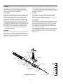
Section 10. Direct Plug
I Bernard Quick Disconnect
A. Removal
Remove liner from gun assembly. Viewing quick disconnect from
feeder end, align wave spring and snap ring with opening access slot
(See Figure 6). Compress large snap ring with internal snap ring pliers
and remove locking sleeve. Remove medium external snap ring from
power pin using external snap ring pliers. Open rigid strain relief and
remove wire assemblies from assembly by compressing the locking
tabs on the contact pins with needle nose pliers and pulling the wire
assemblies from the back. Unthread power pin from rear water block
with appropriate wrenches in a counterclockwise rotation. Inlet and
outlet hoses can be removed from rear water block by cutting Oetiker
clamps with cutting pliers. The gas pin may be removed from the rigid
strain relief by removing the small snap ring and pulling the pin from the
rigid strain relief.
B. Service
Test contact pins for continuity when trigger is engaged. Lubricate
o-rings with silicone lubricant. Inspect all components for cracks,
debris, excessive wear, and breakage. Replace with new components if
safety or performance of product is compromised.
C. Installation
Assemble gas pin into rigid strain relief and secure with small snap ring.
Install inlet and outlet hoses by pushing hose onto barbed fitting on rear
water block and secure with Oetiker clamp. Install power pin onto rear
water block with appropriate wrenches in a clockwise rotation. Install
wire assemblies into the two symmetrical holes on the back side of the
rigid strain relief. Do not cross control wires from side to side. Make
sure control pins are fully seated to ensure proper gun functionality.
Slide the power pin back into the rigid strain relief. Rotate the power pin
until the barbed fittings on rear water block are facing upward and away
from the bottom of the rigid strain relief. (See Figure 7) Once the power
pin is fully seated, secure it by installing the medium snap ring into the
groove on the power pin. Close rigid strain relief and secure by installing
the strain relief spring assembly. Position wave spring and large internal
snap ring in opening access slot. With internal snap ring pliers inserted
through locking sleeve, compress snap ring and slide sleeve into place.
Snap ring must be fully seated in locking sleeve. Locking sleeve must be
able to rotate freely around rigid strain relief. Install liner.
II Euro Direct Plug
A. Removal
Remove liner from gun assembly. Follow the steps required to remove
the complete cable assembly from the rear water block. Inlet and
outlet hoses can be removed from rear water block by cutting Oetiker
clamps with cutting pliers. Disconnect the Euro block lead set from gun
by cutting as close as possible on both sides of the butt connectors
in order to preserve wire for later retermination. Remove screw that
secures Euro block assembly to rigid strain relief. Slide adapter nut
back in order to expose the machined flats on the Euro block assembly.
Remove Euro block from rear water block and rigid strain relief by using
the appropriate wrenches in a counterclockwise rotation.
FIGURE 6
Snap Ring
FIGURE 7
Barbed fittings located
away from bottom of
strain relief as shown
(for inlet / outlet hoses)
14

B. Service
Test contact pins for continuity when trigger is engaged. Lubricate
o-rings with silicone lubricant. Inspect all components for cracks,
debris, excessive wear, and breakage. Replace with new components if
safety or performance of product is compromised.
C. Installation
Place adapter nut onto rigid strain relief and secure by threading rear
water block into Euro block assembly. Using the appropriate wrenches,
tighten Euro block assembly onto the rear water block by rotating
clockwise. Continue tightening connection until barbed fittings on
rear water block are facing upward and away from the bottom of the
rigid strain relief. (See Figure 7) Secure Euro block assembly to rigid
strain relief using screw. Connect Euro block leads to control leads by
connecting with insulated butt connectors. Install inlet and outlet hoses
by pushing hose onto barbed fitting on rear water block and secure with
Oetiker clamp. Follow the steps required to reassemble the complete
cable assembly to the rear water block. Close rigid strain relief and
secure by installing the strain relief spring assembly. Install liner.
III All Other Direct Plugs
A. Removal
Remove liner and rigid strain relief from gun assembly. Inlet and outlet
hoses can be removed from rear water block by cutting Oetiker clamps
with cutting pliers. Position control lead wires as necessary as not to
damage them. Remove power pin from adapter block using appropriate
wrenches in a counterclockwise rotation.
Note: For OXO direct plugs, rigid strain relief must be held gently in
vise while using the appropriate wrench in a counterclockwise rotation
to remove the power pin. Be careful not to crush or deform rigid strain
relief while being held in vise.
B. Service
Test contact pins for continuity when trigger is engaged. Lubricate
o-rings with silicone lubricant. Inspect all components for cracks,
debris, excessive wear, and breakage. Replace with new components if
safety or performance of product is compromised.
C. Installation
Assemble power pin onto adapter block by using appropriate wrenches
in a clockwise rotation. Make sure that the barbed fittings on rear water
block are facing upward and away from the bottom of the rigid strain
relief. (See Figure 7) Install inlet and outlet hoses by pushing hose
onto barbed fitting on rear water block and secure with Oetiker clamp.
Reinstall rigid strain relief and liner.
Note: For OXO direct plugs, rigid strain relief must be held gently in vise
while using the appropriate wrench in a clockwise rotation to install the
power pin. Be careful not to crush or deform rigid strain relief while
being held in vise.
Strain Relief Screw
Liner
Power Pin Tip
Power Cable
Outer Cover
Conduit
Return Hose
Adapter Block
Conduit Set Screw
Typical Direct Plug Construction
Power Pin
Rigid Strain
Relief Bottom
Rigid Strain
Relief Top
Water Block
Water Inlet /
Outlet hoses
Spring Strain Relief
"4/1
"1
0
"2/1
"4/3
"4/1-1
"2/1-1
15

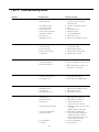
Part V Troubleshooting Guide
PROBLEM POSSIBLE CAUSE CORRECTIVE ACTION
1. Electrode does not feed 1. Feeder relay.
2. Broken control lead.
3. Poor adaptor connection.
4. Worn or broken switch.
5. Improper drive roll size.
6. Drive roll tension misadjusted.
7. Burn back to contact tip.
8. Wrong size liner.
9. Buildup inside of liner.
1. Consult feeder manufacturer.
2 a. Test & connect spare control lead.
b. Install new cable.
3. Test & replace leads and/or contact pins.
4. Replace.
5. Replace with proper size.
6. Adjust tension at feeder.
7. See ‘Contact Tip Burn Back’.
8. Replace with correct size.
9. Replace liner, check condition of electrode.
2. Contact tip burn back 1. Improper voltage and/or wire feed speed.
2. Erratic wire feeding.
3. Improper tip stickout.
4. Improper electrode stickout.
5. Faulty ground.
1. Set parameters.
2. See ‘Erratic Wire Feeding’.
3. Adjust nozzle/tip relationship.
4. Adjust gun to base metal relationship.
5. Repair all cables & connections.
3. Tip disengages from gas diffuser 1. Worn gas diffuser.
2. Improper tip installation.
3. Extreme heat or duty cycle.
1. Replace tip and/or gas diffuser.
2. Install as per ‘Maintenance & Repair’ (Section
3).
3. Replace with heavy duty consumables. See
appropriate spec sheet for details.
5. Erratic arc 1. Worn contact tip.
2. Buildup inside of liner.
3. Wrong tip size.
4. Not enough bend in neck.
1. Replace.
2. Replace liner, check condition of electrode.
3. Replace with correct size tip.
4. Replace with 45º or 60º neck.
4. Short contact tip life 1. Contact tip size.
2. Electrode eroding contact tip.
3. Exceeding duty cycle.
1. Replace with proper size.
2. Inspect and/or change drive rolls.
3. Replace with properly rated Bernard gun.
6. Erratic wire feeding 1. Buildup inside of liner.
2. Wrong size liner.
3. Improper drive roll size.
4. Worn drive roll.
5. Improper guide tube relationship.
6. Improper wire guide diameter.
7. Gaps at liner junctions.
8. Feeder malfunction.
9. Contact tip.
1. Replace liner, check condition of electrode.
2. Replace with new liner of proper size.
3. Replace with proper size drive roll.
4 a. Replace with new drive roll.
b. Stone edge of groove on drive roll.
5 a. Adjust/replace guide as close to drive rolls
as possible.
b. Eliminate all gaps in electrode path.
6. Replace with proper guide diameter.
7 a. Replace with new liner trimming as per
‘Maintenance & Repair’ (Section 5).
b. Replace guide tube/liner, trim as close to
mating component as possible.
8. Consult feeder manufacturer.
9. Inspect and replace.*
16

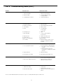
Part V Troubleshooting Guide (cont.)
*In some cases with aluminum and mild steels, it may be necessary to use a contact tip with either a larger or smaller bore size.
7. Extreme spatter 1. Improper machine parameters.
2. Improper tip installation.
3. Improper shielding.
4. Contaminated wire or work piece.
1. Adjust parameters.
2. Adjust nozzle/tip relationship.
3 a. Verify shielding gas coverage.
b. Verify gas mixture.
4. Clean wire and work piece.
8. Porosity in weld 1. Insulator worn.
2. Gas diffuser damaged.
3. Extreme heat or duty cycle.
4. Solenoid faulty.
5. No gas.
6. Flow improperly set.
7. Gas ports plugged.
8. Ruptured gas hose.
9. Control circuit loss.
10. Worn, cut or missing O-rings.
11. Loose fittings.
1. Replace nozzle/insulator.
2. Replace gas diffuser.
3. Replace with heavy duty consumables.
4. Replace solenoid.
5 a. Install full tanks.
b. Check supply.
c. Hose leaks.
6. Adjust.
7 a. Clean or replace gas diffuser.
b. Clean nozzle.
8. Repair or replace cable or line.
9. See ‘Electrode Does Not Feed’.
10. Replace O-rings
11. Tighten gun & cable connections to speci-
fied torque. See ‘Maintenance & Repair’
(Section 8).
9. Gun running hot 1. Exceeding duty cycle.
2. Loose or poor power connection.
3. Improper water flow
4. Exceeds water cooler capacity
1. a. Replace with properly rated Bernard gun.
b. Decrease parameters to within gun rating.
2. a. Clean, tighten or replace cable grounding
connection.
b. Tighten gun & cable connections to
specified torque. See ‘Maintenance & Repair’
(Section 8).
3. Verify proper water flow
4. Replace with properly rated water cooler
10. Liner is discolored full length 1. Short circuit to electrode.
2. Broken copper stranding in power cable.
1. Isolate electrode reel from feeder and drive
block. Consult feeder manufacturers manual.
2. Replace power cable assembly as per
‘Maintenance & Repair’ (Section 8).
11. Sporadic feeding of aluminum electrode 1. Tip galling.
2. Synthetic liner melting.
3. Wire deformed by feed rolls.
1. *Inspect & replace.
2. a. Replace liner.
b. Replace with composite liner.
3. Adjust drive rolls as per feeder manufacturer’s
manual.
PROBLEM POSSIBLE CAUSE CORRECTIVE ACTION
17

NOTES

ADDITIONAL SUPPORT MATERIALS
Foradditionalsupportmaterialssuchasspecsheets,troubleshootinginformation,how-toguidesandvideos,
animations,onlineconfiguratorsandmuchmore,pleasevisitTregaskiss.comorscantheQRCodewithyour
smartphoneforimmediateaccesstoTregaskiss.com/TechnicalSupport.
Bernard
449 W. Corning Rd.
Beecher, IL 60401
Tregaskiss.com
Phone:
Fax:
1-855-MIGWELD (644-9353) (US & Canada)
+1-519-737-3000 (International)
1-708-946-6726
-
 1
1
-
 2
2
-
 3
3
-
 4
4
-
 5
5
-
 6
6
-
 7
7
-
 8
8
-
 9
9
-
 10
10
-
 11
11
-
 12
12
-
 13
13
-
 14
14
-
 15
15
-
 16
16
-
 17
17
-
 18
18
-
 19
19
-
 20
20


Bernard 600 Amp Manual de usuario
- Categoría
- Sistema de soldadura
- Tipo
- Manual de usuario
en otros idiomas
- français: Bernard 600 Amp Manuel utilisateur
- English: Bernard 600 Amp User manual
Artículos relacionados
Otros documentos
-
 Tregaskiss 293039 Iron Pro 450 Self Shielded MIG Gun Manual de usuario
-
 Tregaskiss OM-MF4 Tough Gard Anti-Spatter Multi-Feed System El manual del propietario
-
Miller MA020784U El manual del propietario
-
-
HobartWelders HANDLER 125 EZ AND H-9B GUN El manual del propietario
-
-
-

